Embed Size (px)
Citation preview
5/11/2018 2-Plant Layout - Pipeway Design - slidepdf.com
http://slidepdf.com/reader/full/2-plant-layout-pipeway-design 1/25
Plant Layout - Pipeway Design
Table of Contents
1. General
2. Information Required
3. Evaluation of Information
4. Line Identification
5. Piperack Width
6. Piperack Elevation
7. Line Location in Piperacks
8. Piping Economy in Piperack and its Influence on Plant Layout
9. Piperack General Arrangement Checklist
10.Pipetracks
11. Trenched Piping (Civil Department)
12. Underground Piping (by Civil Department)
Compiled By: Laxmikant Sawleshwarkar CH-2 Page 1 of 25
5/11/2018 2-Plant Layout - Pipeway Design - slidepdf.com
http://slidepdf.com/reader/full/2-plant-layout-pipeway-design 2/25
Plant Layout - Pipeway Design
1. General
The pipeway conveys all main process lines connecting distant pieces of equipment, relief and blowdown headers, all lines leaving and entering the plant, utility lines supplying steam,air, cooling water and inert gas to the plant. Electrical and instrument cable trays are
usually routed in the pipeway. Pipeways are classified by their relative elevation to grade.
1.1 Piperack
Overhead piping supported on steel or concrete bents.
1.2 Pipetrack
Above ground piping supported on concrete sleepers at grade level. (Off site areas whereequipment is well spaced out)
1.3 Trenched Piping ( by Civil Department )
Below ground piping laid in connection trenches. Costly and usually undesirable; unlesstrenches are wide, shallow and well vented, heavy gases may settle and crea
te a fire hazard through the length of the trench. For these reasons, only pump out lines,chemical sewers or chemical drain collection systems are sometimes placed in trenches androuted to a pit or underground collection tank.
1.4 Underground Piping ( by Civil Department )
Piping direct buried below ground level. Due to costly maintenance and the usually corrosivenature of soil, this method of routing is generally reserved for sewer and drain lines. Insome plants, especially in cold climates, cooling water lines are buried below the frostline.This should be determined at the beginning of a job, is generally a Client request.
2. Information Required
2.1 Job Specification
Job specification SP....C100 contains design criteria, agreed between Company and Client,affecting piperack design:
• Battery limit, valving and spade requirements.
• Catwalk, platform and ladder access to valves and relief valves in piperack.
• Minimum headroom and clearances under overhead piping or supporting steel withinareas
• Pipeways and secondary access ways
• Main access roads
• Rail roads
• Standard to be used for minimum spacing of lines in paperacks
Compiled By: Laxmikant Sawleshwarkar CH-2 Page 2 of 25
5/11/2018 2-Plant Layout - Pipeway Design - slidepdf.com
http://slidepdf.com/reader/full/2-plant-layout-pipeway-design 3/25
Plant Layout - Pipeway Design
• Handling and headroom requirements for equipment positioned under piperacks
• Operating and safety requirements affecting piperack and structure design
• Location of cooling water lines underground or above ground
• Trenched piping, if any.
2.2 Process Flow Diagrams
Process flow diagrams show main process lines and lines interconnecting processequipment.
2.3 Engineering Flow Diagrams
Engineering flow diagrams are developed from process flow diagrams and show:
• Pipe sizes. Pipe classes, and line number.
• Valving.
• Manifolding.
• All instrumentation.
• Equipment and lines requiring services, i.e. water steam, air, nitrogen etc.
2.4 Utility Flow Diagrams
Utility flow diagrams show the required services:
• Steam
• Condensate
• Water
• Air
• Gas
And any additional services peculiar to the plant being worked on, e.g.:
• Caustic
• Acid
• And refrigeration lines, etc.
3. Evaluation of Information
3.1 Initial Evaluation
Use plot plan and process flow diagrams to make a preliminary assessment of which portionof process lines will be located in piperack and which lines will interconnect directly tonozzles on adjacent items of equipment. Draw lines to be located on piperacks on print of plot plan. Some idea of utility piping required must be established and included coordinatewith Instrument and Electrical Section to assess what additional rack space may be required
Compiled By: Laxmikant Sawleshwarkar CH-2 Page 3 of 25
5/11/2018 2-Plant Layout - Pipeway Design - slidepdf.com
http://slidepdf.com/reader/full/2-plant-layout-pipeway-design 4/25
Plant Layout - Pipeway Design
to accommodate cable trays. This action provides a preliminary visual idea of the piperackspace required.
3.2 Development
With the receipt of engineering flow diagrams and utility flow diagrams, a more complete
and accurate assessment of rack space is possible. Utility headers generally run the wholelength of the piperack, so should be taken into account when estimating additional spacerequired. To assist Process Department in sizing utility headers in the pipeway a line routingon a repro of the plot plan, showing order of take-offs is required.
4. Line Identification
Certain types of piping require special consideration:
4.1 Process Lines
Lines interconnecting nozzles on process equipment more than 6M apart (closer speced
equipment may be directly interconnecting inside piping areas).
• Products lines which run from vessels, exchangers or pump to battery / unit limits
• Crude or other charge lines entering the unit which run along piperack beforeconnecting to process equipment, furnaces, exchangers, holding drums or boosterpumps.
4.2 Relief Headers
Individual relief lines, blowdown lines and flare lines should be self draining from all relief valve outlets to knock-out drum, flare stack or to a point at the plant limit. To achieve this,
lines will connect into the top of the header and at 45 degrees in direction of flow. Toeliminate pockets, and obtain required slope to knock-out drum some relief headers mustbe placed above the main piperack.
4.3 Instrument and Electrical Cable Trays
Often instrument and electrical cable trays are supported on the piperack track. Space mustbe allocated to accommodate them from the outset. Due to the possibility of inducedcurrent interference instrument and communication cable trays must be located away fromelectrical and power cable trays. Consult with Instrument /Electrical Department forseparation requirements.
5. Piperack Width
The width of piperack is influenced by :
• The number of lines
• Electrical/instrument cable trays.
• Space for future lines.
Compiled By: Laxmikant Sawleshwarkar CH-2 Page 4 of 25
5/11/2018 2-Plant Layout - Pipeway Design - slidepdf.com
http://slidepdf.com/reader/full/2-plant-layout-pipeway-design 5/25
Plant Layout - Pipeway Design
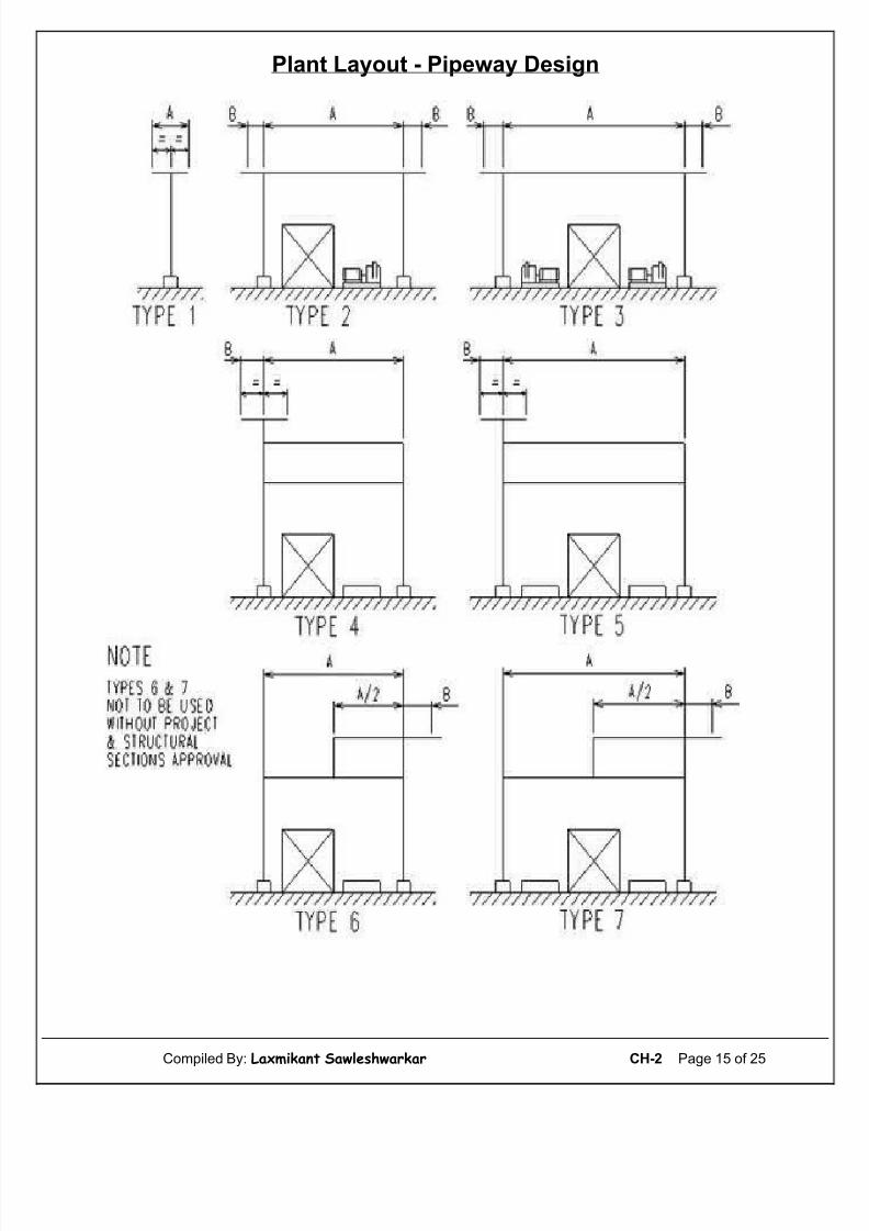
The width of a piperack may be calculated using the following method : First estimatenumber of lines as described. Add up the number of lines up to 18” diameter in the mostdense section of the piperack.
The total width in meters (W) will be :
W = ( f x N x S ) + A meters
Where f, safety factor = 1.5, if the lines have been laid out as described in initial evaluation.
Where f, safety factor = 1.2, if the lines have been laid out as described underdevelopment.
N = number of lines below 18” diameter
S = average estimated spacing between lines in millimeters.
Usually - S = 300 mm
Usually - S = 230 mm ( if lines in piperack are smaller than 10” )
A = additional width required meters for :
• Lines larger than 18”.
• Future lines.
• Instrument and electrical cable trays.
• Any slot for pump discharge lines 500 mm - 1 meter.
The total width is thus obtained. If W is bigger than 9M usually two piperack levels will berequired.
Note : At the beginning of a job, `W` should usually include 30 - 40% of clear space forfuture lines.
The width of the piperack may be increased or determined by the space requirement,and/or access to equipment arranged under the piperack.
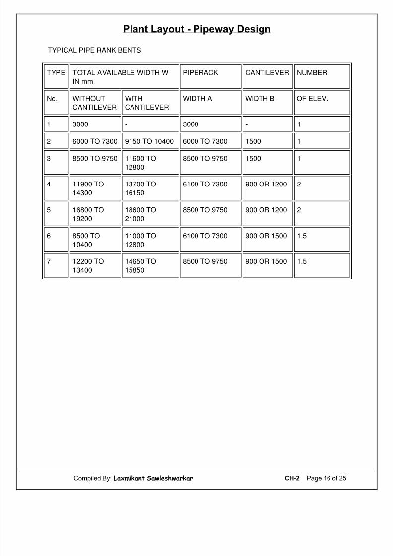
Below figure shows typical piperacks bents with tabulated dimensions. Total availablepiperack width of each type of support is included. This table can be used for selection. Themost commonly used piperack supports are types 2, 3, 4 and 5.
5.1 Spacing between Piperack Bents
Normal spacing between piperack bents varies between 4.6M to 6M.
This may be increased to a maximum of 8M consideration must be given to :
• Smaller lines which must be supported more frequently ( see Company designspecification “recommended span between pipe supports” )
Compiled By: Laxmikant Sawleshwarkar CH-2 Page 5 of 25
5/11/2018 2-Plant Layout - Pipeway Design - slidepdf.com
http://slidepdf.com/reader/full/2-plant-layout-pipeway-design 6/25
Plant Layout - Pipeway Design
• Liquid filled lines requiring shorter span than gas filled lines
• Hot lines which span shorter distances than cold lines of the same size and wallthickness
• Insulated lines; small bore, cold - insulated lines due to weight of insulation must besupported at relatively short intervals
• Space requirements of equipment at grade can sometimes influence piperack bentspacing.
6. Piperack Elevation
Piperack elevation is determined by the highest requirement of the following :
• Headroom over main road
• Headroom for access to equipment under the piperack
• Headroom under lines interconnecting the piperack and equipment located outside.
The size of steel or concrete beam supporting overhead piping must be taken intoconsideration. Headroom requirements for each job are detailed in Company specificationno. C100 and coordination procedure.
6.1 Elevation at Piperack Intersection
Where two two-tier piperacks meet, it is essential that elevations of lateral piperacks slotbetween elevations of main piperack.
Figure 2A illustrates this requirement. Choice of top elevation of lateral piperack midwaybetween the top an bottom main piperack elevation allows turning up or down at theintersection.
Generally, lines running at right angles to main piperack are assigned elevations 500 mm to1 meter higher or lower (depending on headroom requirements) than lines running in mainpiperack. 500 mm differential between pipe runs is the absolute minimum.
Figure 2B shows a piperack intersection where the respective main and lateral piperackelevations do not slot between each other. This design complicates routing of lines frompiperack to the other, especially where lines run on the bottom levels of both piperacks.Avoid this design at all cost.
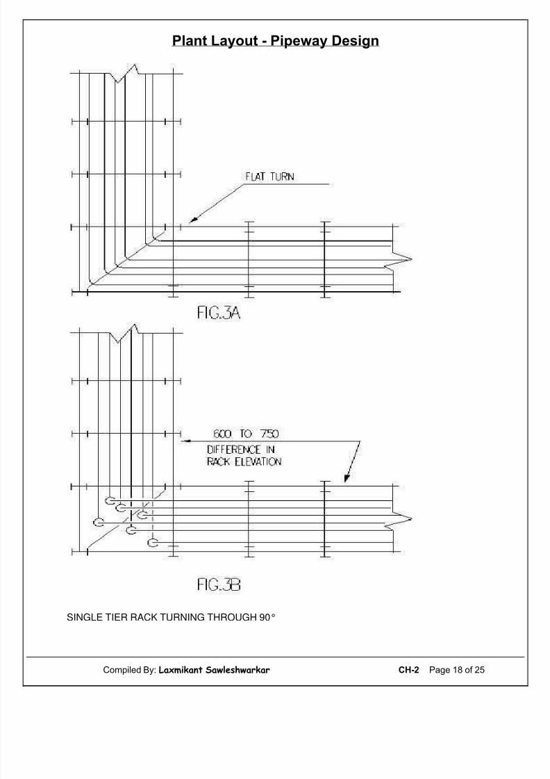
Where a single tier piperack turns through 90°, and all lines can be kept in the samesequence in both directions, no elevation difference is necessary. When lines sequence
changes, introduce an elevation change at the turn. See below figures.
7. Line Location in Piperacks
7.1 One Tier Piperacks
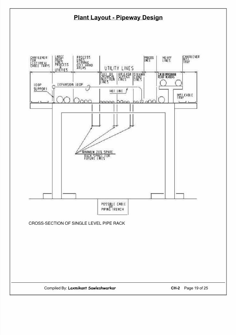
Below figure shows a cross section of a single level piperack. Heavy lines (very largediameter lines, large bore lines full of liquid) regardless of service are placed over or nearthe piperack columns. This simplifies steelwork or concrete piperack design. Centrally
Compiled By: Laxmikant Sawleshwarkar CH-2 Page 6 of 25

5/11/2018 2-Plant Layout - Pipeway Design - slidepdf.com
http://slidepdf.com/reader/full/2-plant-layout-pipeway-design 7/25
Plant Layout - Pipeway Design
loaded column and reduced bending moment on the beam will result in a lighter overalldesign.
Place process and relief lines next to these. Lines serving left hand areas of plant on left,lines serving right hand areas on the right.
The central piperack portion is reserved for utility lines which may serve both right and lefthand areas on the plant. However, utility lines serving one or two pieces of equipmentshould be on the same side of the piperack as the equipment to which they connect.
Process lines which interconnect equipment on both sides of the piperack should be placedclose to utility lines, and can be on either side of piperack, depending upon location of equipment they serve. The position of product lines is influenced by their routing afterleaving the unit, right, (left) turning lines should be on the right (left) hand side of thepiperack.
If possible, a centrally placed section of the piperack is reserved for future lines. Thissection should run the whole length of the piperack. Should this be impracticable, a series of
smaller sections, running the whole length of the piperack, are to be provided. (see belowfigure).
7.2 Two Tier Piperacks
Where the number of lines dictate the use of a two level piperack, utility lines are placed onthe top level and process lines on the bottom level. This is not a rigid rule and where pipingeconomy dictates certain process lines may be routed on the top level. Line sequencearrangement should follow the philosophy outlined previously.
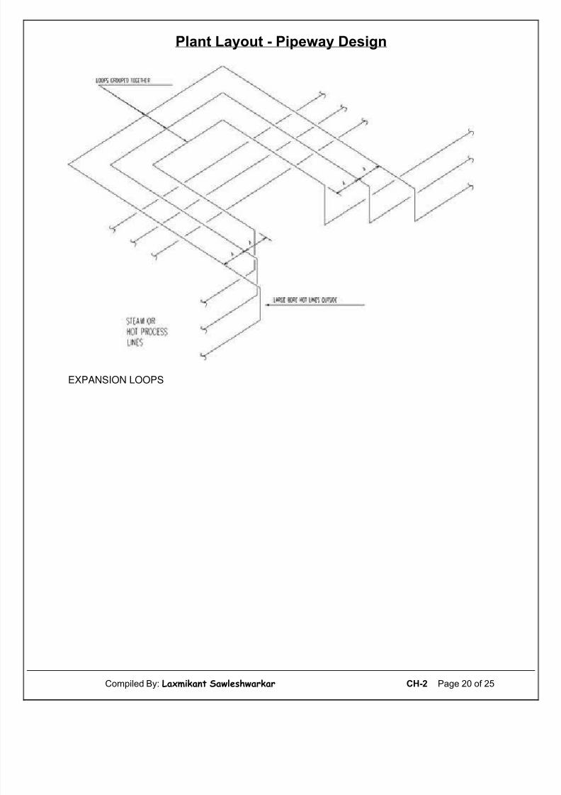
7.3 Position of Hot Lines
It is advantageous for pipe supports to group hot lines requiring expansion loops together,preferably on side of the piperack. Horizontally elevated loops over the piperack arecommonly used to minimize the effects of expansion on hot lines, the hottest and largestline being on the outside. See below figures.
7.4 Line Spacing
For line spacing use “recommended piperack spacing” per table in Job Specification C100. Itshould be noted that in certain cases, it is necessary to deviate from the standards quotedabove, e.g., see below figures at point “A” due to possible differential expansion line spacingmay have to be increased to allow for movement of lines at start up.
To determine expansion of hot lines, use Company engineering guide, Attachment “thermalexpansion of pipe materials”.
Compiled By: Laxmikant Sawleshwarkar CH-2 Page 7 of 25

5/11/2018 2-Plant Layout - Pipeway Design - slidepdf.com
http://slidepdf.com/reader/full/2-plant-layout-pipeway-design 8/25
Plant Layout - Pipeway Design
8. Piping Economy in Piperack and its Influence on Plant Layout
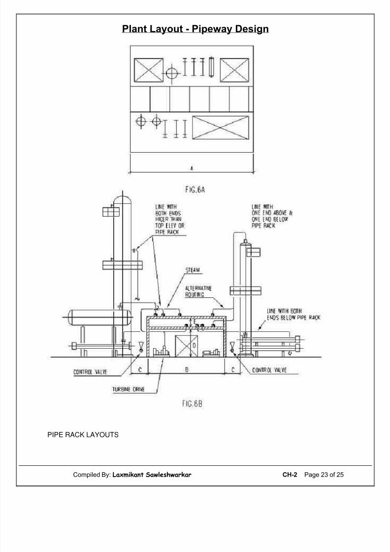
8.1 Piperack Layout
Plant layout determines the main piperack piping runs. The shape of piperack is the result of plant arrangements, site conditions, Client’s requirements and overall plant economy. See
below figures.
Piping economy depends primarily on the length of lines routed in the piperack. Belowfigures shows critical dimensions which influence overall cost. These dimensions depend onoverall plant layout and should be carefully considered when the plot is arranged.
Dimension “A”, (see below figures) is the total length of piperack and is governed by thenumber and size of equipment, structures and buildings arranged along both sides of thepiperack. On average, 3 meters of piperack length are required per item of processequipment, good lay-out can reduce piperack length. (Thereby costs).
Equipment in pairs, stacked exchangers supported from towers, two vessels combined into
one, closely located towers with common platforms, process equipment located - underpiperack - are examples which help shorten piperack length. In a well arranged plant,average length of piperack per item of process equipment can be reduced to 2.1 meters to2.4 meters.
Careful selection of dimensions B and C, below figure will minimize interconnectionequipment on opposite sides of piperack. C is normally no more than 1.8 meters to 3meters.
Dimensions D and E, (see below figure), minimize. Overgenerous dimensioning here willincrease vertical pipe lengths. Maximize use of available platforms for access to valves.Where air fins are located above the piperack, use associated air fin maintenance platforms,
modifying their extent if necessary. This method will be cheaper than adding specialplatforms in the piperack.
9. Piperack General Arrangement Checklist
Critically review piperack layout against latest information. Some lines should requirererouting for maximum piping economy. Check loops required for nesting. As many loops aspossible should be combined in a loop bay having due regard to stress requirements.
9.1 Vibrating Lines
• Avoid changes in direction
• Avoid long overhanging bends without support
• Use bends where possible (check with job specification)
• Tees to be avoided as far as possible, flow should enter along run of tee and never
in the branch.
Low point pockets to be avoided in the following lines :
• Steam (trap any pockets and dead ends)
Compiled By: Laxmikant Sawleshwarkar CH-2 Page 8 of 25
5/11/2018 2-Plant Layout - Pipeway Design - slidepdf.com
http://slidepdf.com/reader/full/2-plant-layout-pipeway-design 9/25
Plant Layout - Pipeway Design
• Slurry
• Blowdown (these lines must be self-draining)
• Caustic, acid and Phenol (all these services to be self draining)
• R.V.’s both inlet and outlet
•
Vapour to knock-out pots• Heavy products, bitumen, wax
• Pump suctions
• Lethal and toxic substances
High point pockets to be avoided in the following lines :
• Pump suctions
• Light ends
• Vapour/liquid mixes (hot tower bottoms - reflux lines)
• Crude lines
On hot lines, check shoe requirements and clearances at changes of direction (pipeexpansion).
Provide vents at high points.
Provide drains at low points.
Provide steam traps at : low points, up-stream of loops and dead ends, via condensate driplegs.
On steam, air and condensate headers, take-offs to be from top of headers. RV headershigh or low elevation. Before finalizing elevation of RV header consider elevation of all RVdischarges and elevation of knock-out drum at flare.
Bends, if used : (check with job specification).
• Where lines change elevation bends may be used providing difference in elevation isadequate and specification permits
• Header take-offs in piperacks, use elbows
• Special piping:
• Catalyst lines 5D (minimum).
• Vibrating piping 5D.
• Small bore usually below 2” (Client preferred).
Pipe setting: to be avoided in large bore lines. Small bore lines to be set only whereabsolutely necessary.
Pipe Stress Department will advise which piping systems require formal stress analysis.
Compiled By: Laxmikant Sawleshwarkar CH-2 Page 9 of 25
5/11/2018 2-Plant Layout - Pipeway Design - slidepdf.com
http://slidepdf.com/reader/full/2-plant-layout-pipeway-design 10/25
Plant Layout - Pipeway Design
Supports : avoid long unsupported overhangs.
Steelwork clearances : check steelwork clearances for addition of fireproofing (lowerelevation of piperack), brackets, gussets and thermal expansion of lines.
Concrete support clearances: check for local thickening of concrete columns due to
method of fabrication adopted (i.e. corbels).
Valves: check clearances and accessibility. Make full of extending platforms for operation(i.e. air fin maintenance platforms).
Chain wheels: preferably do not use. However, if necessary, check chain clearances.Spading and valving at battery limit : check for accessibility if necessary, provide accessplatform.
10. Pipetracks
This type of pipeway is generally associated with offsite areas where equipment is well
spaced out, and land space is not a premium.
10.1 Pipetrack Width
Pipetrack width may be estimated using the method detailed previously for piperack.
10.2 Spacing of Pipetrack Sleepers
Pipetrack sleepers are relatively cheap thus piping economy is dictated by therecommended span of the smallest line in the track.
Where small bore lines are few, sleeper spacing may be determined by the pipe span of large bore lines provided small bore lines are supported off the larger lines at adequateintervals. An angle with “U” bolts is sufficient (check with Pipe Support Section).
For recommended pipe support spans, use Company standard.
On an average minimum span = 3 meters
maximum span = 6 meters
depending on line size and substance carried in pipes, (i.e. gas or liquid).
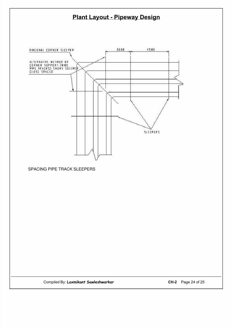
All lines must be supported. At changes of direction due to long overhangs, for narrowpipetracks a diagonal corner sleeper is recommended. On wide pipetracks, use alternativemethod of two short sleepers located near corner. See below figures.
10.3 Pipetrack Elevation
Pipetrack elevation is set by maintenance access to piping items located underneath thepipetrack, i.e. drains and steam traps. A minimum of 12”/300 mm clearance between
Compiled By: Laxmikant Sawleshwarkar CH-2 Page 10 of 25
5/11/2018 2-Plant Layout - Pipeway Design - slidepdf.com
http://slidepdf.com/reader/full/2-plant-layout-pipeway-design 11/25
Plant Layout - Pipeway Design
underneath of lines and grade is recommended; where necessary, this may be increased to18”/450 mm.
As pipetracks are generally single tier, no change in elevation is necessary at changes of direction. This is effected by use of a flat turn. See below figures.
For individual line elevation above sleeper, use Company job specification no. C4 “elevationof hot insulated lines”.
10.4 Line Location
Line location with reference to bore and weight is unnecessary, as all pipes are supportedon sleepers which rest directly on the ground. Line routing is all important. All linesinterconnecting process equipment and/or storage tanks located on left-hand side of pipetrack are placed to the left-hand side. Similarly, all lines interconnecting equipmentlocated on right-hand side of pipetrack are placed to the right of pipetrack. Linesinterconnecting equipment located on either side of pipetrack are placed near the center of pipetrack.
10.5 Line Spacing
Use Company job specification no. C100 “recommended pipetrack spacing”
10.6 Road Crossings
The standard method is to provide culverts under access roads. Elevating piping on a cross-over rack is expensive and introduces unnecessary pockets in the lines thus routed. Whendetermining width and height of culvert, care must be taken to allow sufficient room roundthe pipework for maintenance, insulation and painting. Where only one or two lines cross aroad, crossing may be by means of sleeves set under roadway.
10.7 Access Ways
In areas needing frequent access, platforms may be provided across pipetrack.
10.8 Valves
Where possible, these should be grouped at the edge of an access platform for ease of operation. Drain valves where possible should be brought to outside of pipetrack for ease of operation. The same applies to steam trap assemblies.
10.9 Expansion Loops
Horizontally elevated expansion loops above pipetrack should be provided where necessary.Group all hot lines requiring expansion loops, hottest and largest line on the outside, on oneside of pipetrack. (Generally, the side chosen is that side which has the highest number of take-offs serving equipment on that side).
Compiled By: Laxmikant Sawleshwarkar CH-2 Page 11 of 25
5/11/2018 2-Plant Layout - Pipeway Design - slidepdf.com
http://slidepdf.com/reader/full/2-plant-layout-pipeway-design 12/25
Plant Layout - Pipeway Design
11. Trenched Piping (Civil Department)
In most plants, trenches are avoided due to problems associated with this type of pipeway:
• High initial cost
•
Fire hazard
Where trenchers are used to route lines such as:
• Pump out lines
• Chemical sewers
• Chemical drains
Trenchers must be enough to allow sufficient clearance between trench wall and piping. 150mm between outside of pipe and inside of wall is the minimum acceptable clearance. Thiswill allow for installation of piping, painting and future maintenance. See below figures.Total width of trench required may be determined by using method detailed above. PipingDepartment will advise Civil Department of requirements.
11.1 Line Spacing
Use Company job specification C100. “recommended piperack spacing”.
Line location in a trench carrying a number of lines should be carefully chosen for maximumpiping economy consistent with stress requirements, if any.
Open trenches require drains to stop accumulation of surface water. Trench bottom shouldbe sloped towards drain points. In this case, pipe supporting is by means of angle steel or I
beams set into the walls, allowing bottom for free drainage to nearest drain point.
This method allows drainage of a trench by a minimum of drain points between each pipesupport as would be the case of solid concrete pipe supports built up from the trench.Before proceeding on trench drainage check with coordination procedure and CivilDepartment for water table level.
11.2 Safety Precautions
Most trenches have either a cover of concrete slabs or a grating.
Where flammable liquids are carried in trenched lines, a fire break is provided at suitable
intervals along a trench and at each intersection. This generally consists of two concretewalls 1 M - 1.25 M apart, with the space in between filled with sand. Where highlyflammable gasses are carried, the whole trench, after installation of piping, is back filledwith sand. Piping will advise Civil Department of requirements.
Compiled By: Laxmikant Sawleshwarkar CH-2 Page 12 of 25
5/11/2018 2-Plant Layout - Pipeway Design - slidepdf.com
http://slidepdf.com/reader/full/2-plant-layout-pipeway-design 13/25
Plant Layout - Pipeway Design
12. Underground Piping (by Civil Department)
Keep buried piping to a minimum. Generally only sewer drain lines and fire mains arelocated below ground. In some cases due to Client or climate requirements, cooling waterlines are also buried below the frost line.
With future maintenance in mind, buried lines should be located well clear of foundations,and if running side by side, well spaced out. A minimum of 300 mm clearance is necessarybetween foundations and lines and between the lines themselves.
Above ground safe drain-tails will enter below ground drain line via a tundish (concentricreducer normally) or if a sealed system and cooling water lines by a flanged stub raisedabove ground.
Flanged connections should be a minimum of 300 mm above prevalent grade level. It isadvantageous to set a common level for all these take offs at the outset of the job. Whenlocating tie-in connections to underground systems, especially from elevated drain points,and adjacent to equipment plinths, ensure adequate clearance.
All buried steel pipes should have applied a corrosion resistant coating and wrapping.
Deep valve boxes for buried lines should be designed with ample room inside the box for amaintenance man to bend over and use wrenches for tightening flanges of re-packingvalves. Consideration should be given to the use of concrete pipe in lieu of square boxes.
The criteria for a good underground piping design should be ease of maintenance. Pipingshould be so spaced as to allow easy digging out and replacement of faulty sections; for thisreason, never run underground piping under or through foundations.
Compiled By: Laxmikant Sawleshwarkar CH-2 Page 13 of 25

5/11/2018 2-Plant Layout - Pipeway Design - slidepdf.com
http://slidepdf.com/reader/full/2-plant-layout-pipeway-design 14/25
Plant Layout - Pipeway Design
Figures - Table
Compiled By: Laxmikant Sawleshwarkar CH-2 Page 14 of 25
5/11/2018 2-Plant Layout - Pipeway Design - slidepdf.com
http://slidepdf.com/reader/full/2-plant-layout-pipeway-design 15/25
Plant Layout - Pipeway Design
Compiled By: Laxmikant Sawleshwarkar CH-2 Page 15 of 25
5/11/2018 2-Plant Layout - Pipeway Design - slidepdf.com
http://slidepdf.com/reader/full/2-plant-layout-pipeway-design 16/25
Plant Layout - Pipeway Design
TYPICAL PIPE RANK BENTS
TYPE TOTAL AVAILABLE WIDTH W
IN mm
PIPERACK CANTILEVER NUMBER
No. WITHOUTCANTILEVER
WITHCANTILEVER
WIDTH A WIDTH B OF ELEV.
1 3000 - 3000 - 1
2 6000 TO 7300 9150 TO 10400 6000 TO 7300 1500 1
3 8500 TO 9750 11600 TO
12800
8500 TO 9750 1500 1
4 11900 TO
14300
13700 TO
16150
6100 TO 7300 900 OR 1200 2
5 16800 TO
19200
18600 TO
21000
8500 TO 9750 900 OR 1200 2
6 8500 TO
10400
11000 TO
12800
6100 TO 7300 900 OR 1500 1.5
7 12200 TO
13400
14650 TO
15850
8500 TO 9750 900 OR 1500 1.5
Compiled By: Laxmikant Sawleshwarkar CH-2 Page 16 of 25

5/11/2018 2-Plant Layout - Pipeway Design - slidepdf.com
http://slidepdf.com/reader/full/2-plant-layout-pipeway-design 17/25
Plant Layout - Pipeway Design
TYPICAL PIPE RANK INTERSECTION
Compiled By: Laxmikant Sawleshwarkar CH-2 Page 17 of 25
5/11/2018 2-Plant Layout - Pipeway Design - slidepdf.com
http://slidepdf.com/reader/full/2-plant-layout-pipeway-design 18/25
Plant Layout - Pipeway Design
SINGLE TIER RACK TURNING THROUGH 90°
Compiled By: Laxmikant Sawleshwarkar CH-2 Page 18 of 25
5/11/2018 2-Plant Layout - Pipeway Design - slidepdf.com
http://slidepdf.com/reader/full/2-plant-layout-pipeway-design 19/25
Plant Layout - Pipeway Design
CROSS-SECTION OF SINGLE LEVEL PIPE RACK
Compiled By: Laxmikant Sawleshwarkar CH-2 Page 19 of 25
5/11/2018 2-Plant Layout - Pipeway Design - slidepdf.com
http://slidepdf.com/reader/full/2-plant-layout-pipeway-design 20/25
Plant Layout - Pipeway Design
EXPANSION LOOPS
Compiled By: Laxmikant Sawleshwarkar CH-2 Page 20 of 25

5/11/2018 2-Plant Layout - Pipeway Design - slidepdf.com
http://slidepdf.com/reader/full/2-plant-layout-pipeway-design 21/25
Plant Layout - Pipeway Design
PIPE RACK LAYOUTS
Compiled By: Laxmikant Sawleshwarkar CH-2 Page 21 of 25

5/11/2018 2-Plant Layout - Pipeway Design - slidepdf.com
http://slidepdf.com/reader/full/2-plant-layout-pipeway-design 22/25
Plant Layout - Pipeway Design
Compiled By: Laxmikant Sawleshwarkar CH-2 Page 22 of 25
5/11/2018 2-Plant Layout - Pipeway Design - slidepdf.com
http://slidepdf.com/reader/full/2-plant-layout-pipeway-design 23/25
Plant Layout - Pipeway Design
PIPE RACK LAYOUTS
Compiled By: Laxmikant Sawleshwarkar CH-2 Page 23 of 25
5/11/2018 2-Plant Layout - Pipeway Design - slidepdf.com
http://slidepdf.com/reader/full/2-plant-layout-pipeway-design 24/25
Plant Layout - Pipeway Design
SPACING PIPE TRACK SLEEPERS
Compiled By: Laxmikant Sawleshwarkar CH-2 Page 24 of 25

5/11/2018 2-Plant Layout - Pipeway Design - slidepdf.com
http://slidepdf.com/reader/full/2-plant-layout-pipeway-design 25/25
Plant Layout - Pipeway Design
TRENCHED PIPING
Compiled By: Laxmikant Sawleshwarkar CH-2 Page 25 of 25