Embed Size (px)
Citation preview
ENVIRONMENTAL IMPACT REPORT (Revision 01) - ENVIRONMENTAL IMPACT ASSESSMENT FOR A PROPOSED 75 MW CONCENTRATING SOLAR THERMAL POWER PLANT AND ASSOCIATED INFRASTRUCTURE IN THE SIYANDA DISTRICT, NORTHERN CAPE
E02.JNB.000674 February 2011 Solafrica Thermal Energy (Pty) Ltd 2
18
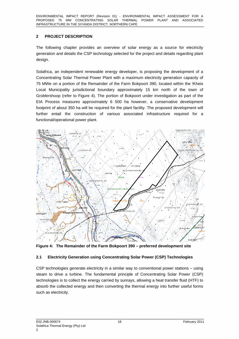
2 PROJECT DESCRIPTION The following chapter provides an overview of solar energy as a source for electricity generation and details the CSP technology selected for the project and details regarding plant design. Solafrica, an independent renewable energy developer, is proposing the development of a Concentrating Solar Thermal Power Plant with a maximum electricity generation capacity of 75 MWe on a portion of the Remainder of the Farm Bokpoort 390, located within the !Kheis Local Municipality jurisdictional boundary approximately 15 km north of the town of Groblershoop (refer to Figure 4). The portion of Bokpoort under investigation as part of the EIA Process measures approximately 6 500 ha however, a conservative development footprint of about 350 ha will be required for the plant facility. The proposed development will further entail the construction of various associated infrastructure required for a functional/operational power plant.
Figure 4: The Remainder of the Farm Bokpoort 390 – preferred development site 2.1 Electricity Generation using Concentrating Solar Power (CSP) Technologies CSP technologies generate electricity in a similar way to conventional power stations – using steam to drive a turbine. The fundamental principle of Concentrating Solar Power (CSP) technologies is to collect the energy carried by sunrays, allowing a heat transfer fluid (HTF) to absorb the collected energy and then converting the thermal energy into further useful forms such as electricity.
ENVIRONMENTAL IMPACT REPORT (Revision 01) - ENVIRONMENTAL IMPACT ASSESSMENT FOR A PROPOSED 75 MW CONCENTRATING SOLAR THERMAL POWER PLANT AND ASSOCIATED INFRASTRUCTURE IN THE SIYANDA DISTRICT, NORTHERN CAPE
E02.JNB.000674 February 2011 Solafrica Thermal Energy (Pty) Ltd 2
19
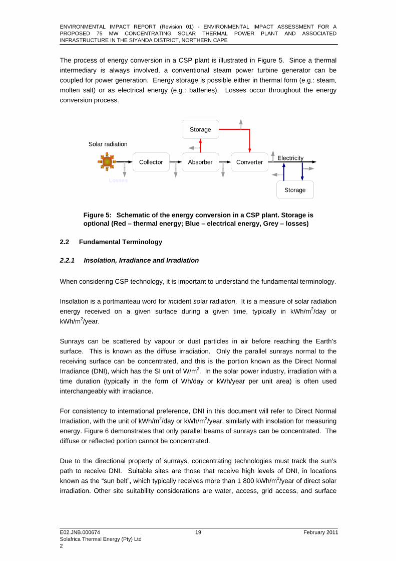
The process of energy conversion in a CSP plant is illustrated in Figure 5. Since a thermal intermediary is always involved, a conventional steam power turbine generator can be coupled for power generation. Energy storage is possible either in thermal form (e.g.: steam, molten salt) or as electrical energy (e.g.: batteries). Losses occur throughout the energy conversion process.
Solar radiation
Collector Absorber
Storage
Converter
Storage
Electricity
Losses
Figure 5: Schematic of the energy conversion in a CSP plant. Storage is optional (Red – thermal energy; Blue – electrical energy, Grey – losses)
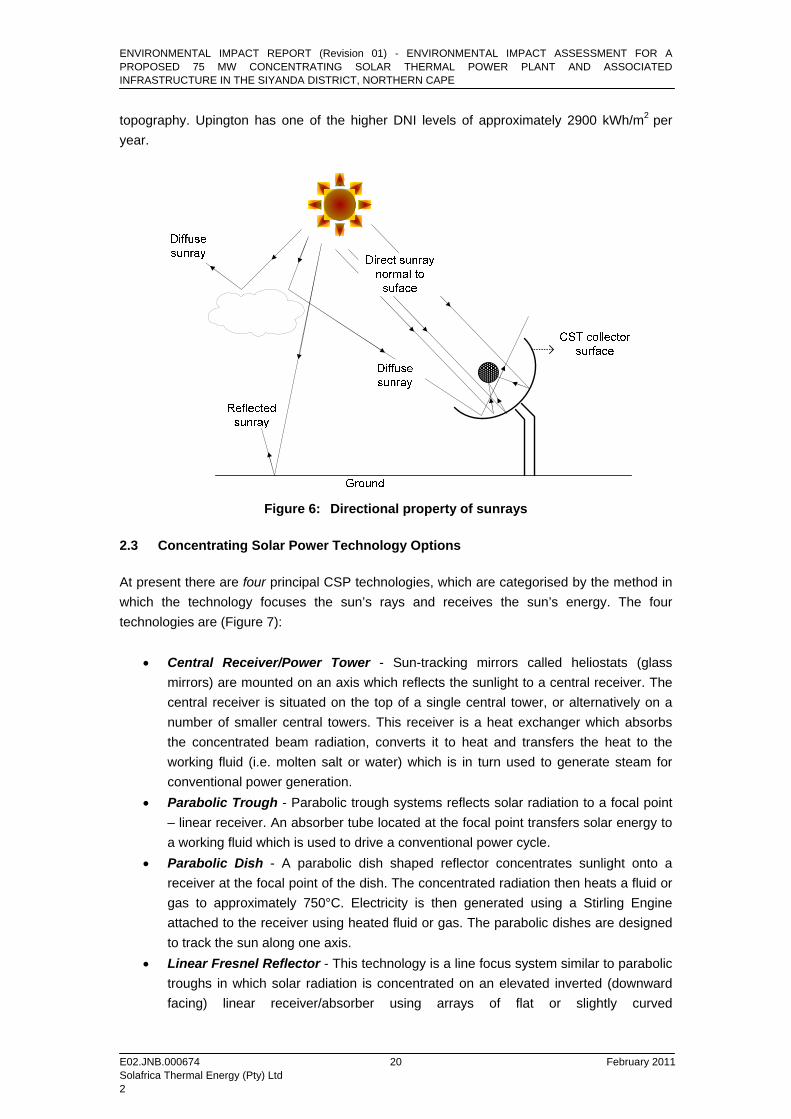
2.2 Fundamental Terminology 2.2.1 Insolation, Irradiance and Irradiation When considering CSP technology, it is important to understand the fundamental terminology. Insolation is a portmanteau word for incident solar radiation. It is a measure of solar radiation energy received on a given surface during a given time, typically in kWh/m2/day or kWh/m2/year. Sunrays can be scattered by vapour or dust particles in air before reaching the Earth’s surface. This is known as the diffuse irradiation. Only the parallel sunrays normal to the receiving surface can be concentrated, and this is the portion known as the Direct Normal Irradiance (DNI), which has the SI unit of W/m2. In the solar power industry, irradiation with a time duration (typically in the form of Wh/day or kWh/year per unit area) is often used interchangeably with irradiance. For consistency to international preference, DNI in this document will refer to Direct Normal Irradiation, with the unit of kWh/m2/day or kWh/m2/year, similarly with insolation for measuring energy. Figure 6 demonstrates that only parallel beams of sunrays can be concentrated. The diffuse or reflected portion cannot be concentrated. Due to the directional property of sunrays, concentrating technologies must track the sun’s path to receive DNI. Suitable sites are those that receive high levels of DNI, in locations known as the “sun belt”, which typically receives more than 1 800 kWh/m2/year of direct solar irradiation. Other site suitability considerations are water, access, grid access, and surface
ENVIRONMENTAL IMPACT REPORT (Revision 01) - ENVIRONMENTAL IMPACT ASSESSMENT FOR A PROPOSED 75 MW CONCENTRATING SOLAR THERMAL POWER PLANT AND ASSOCIATED INFRASTRUCTURE IN THE SIYANDA DISTRICT, NORTHERN CAPE
E02.JNB.000674 February 2011 Solafrica Thermal Energy (Pty) Ltd 2
20
topography. Upington has one of the higher DNI levels of approximately 2900 kWh/m2 per year.
Figure 6: Directional property of sunrays
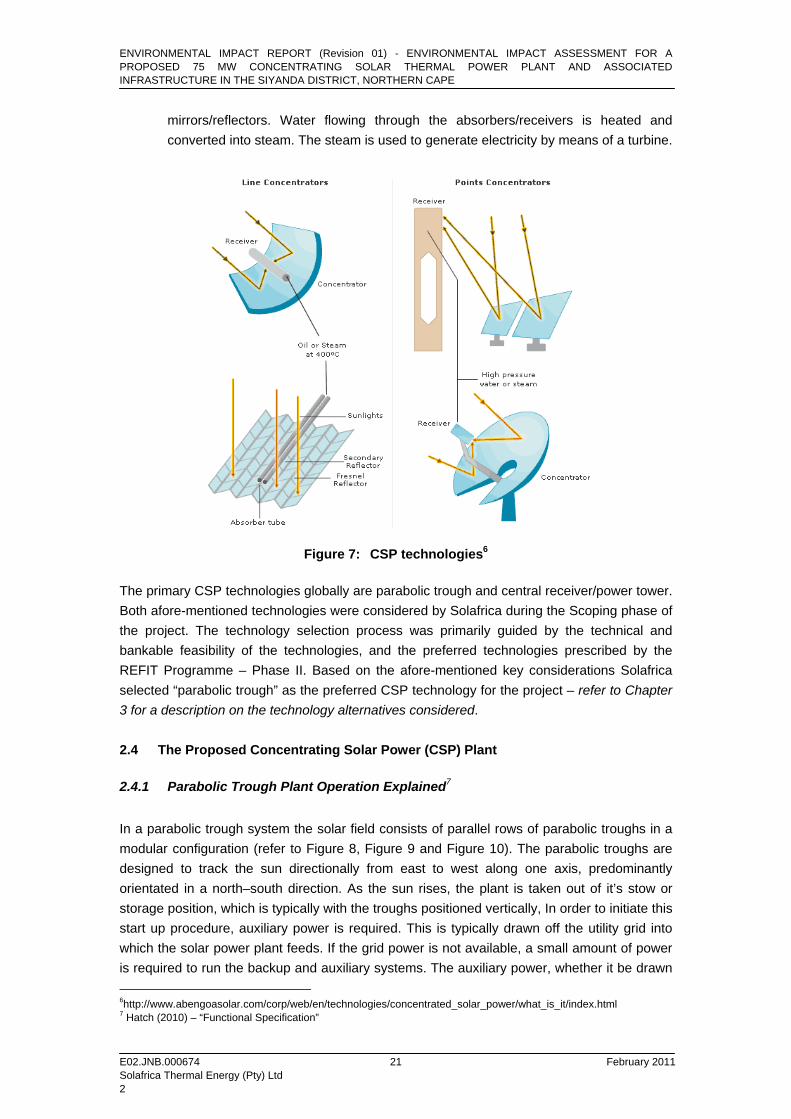
2.3 Concentrating Solar Power Technology Options At present there are four principal CSP technologies, which are categorised by the method in which the technology focuses the sun’s rays and receives the sun’s energy. The four technologies are (Figure 7):
• Central Receiver/Power Tower - Sun-tracking mirrors called heliostats (glass mirrors) are mounted on an axis which reflects the sunlight to a central receiver. The central receiver is situated on the top of a single central tower, or alternatively on a number of smaller central towers. This receiver is a heat exchanger which absorbs the concentrated beam radiation, converts it to heat and transfers the heat to the working fluid (i.e. molten salt or water) which is in turn used to generate steam for conventional power generation.
• Parabolic Trough - Parabolic trough systems reflects solar radiation to a focal point – linear receiver. An absorber tube located at the focal point transfers solar energy to a working fluid which is used to drive a conventional power cycle.
• Parabolic Dish - A parabolic dish shaped reflector concentrates sunlight onto a receiver at the focal point of the dish. The concentrated radiation then heats a fluid or gas to approximately 750°C. Electricity is then generated using a Stirling Engine attached to the receiver using heated fluid or gas. The parabolic dishes are designed to track the sun along one axis.
• Linear Fresnel Reflector - This technology is a line focus system similar to parabolic troughs in which solar radiation is concentrated on an elevated inverted (downward facing) linear receiver/absorber using arrays of flat or slightly curved
ENVIRONMENTAL IMPACT REPORT (Revision 01) - ENVIRONMENTAL IMPACT ASSESSMENT FOR A PROPOSED 75 MW CONCENTRATING SOLAR THERMAL POWER PLANT AND ASSOCIATED INFRASTRUCTURE IN THE SIYANDA DISTRICT, NORTHERN CAPE
E02.JNB.000674 February 2011 Solafrica Thermal Energy (Pty) Ltd 2
21
mirrors/reflectors. Water flowing through the absorbers/receivers is heated and converted into steam. The steam is used to generate electricity by means of a turbine.
Figure 7: CSP technologies6
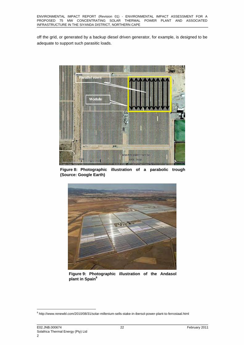
The primary CSP technologies globally are parabolic trough and central receiver/power tower. Both afore-mentioned technologies were considered by Solafrica during the Scoping phase of the project. The technology selection process was primarily guided by the technical and bankable feasibility of the technologies, and the preferred technologies prescribed by the REFIT Programme – Phase II. Based on the afore-mentioned key considerations Solafrica selected “parabolic trough” as the preferred CSP technology for the project – refer to Chapter 3 for a description on the technology alternatives considered. 2.4 The Proposed Concentrating Solar Power (CSP) Plant 2.4.1 Parabolic Trough Plant Operation Explained7 In a parabolic trough system the solar field consists of parallel rows of parabolic troughs in a modular configuration (refer to Figure 8, Figure 9 and Figure 10). The parabolic troughs are designed to track the sun directionally from east to west along one axis, predominantly orientated in a north–south direction. As the sun rises, the plant is taken out of it’s stow or storage position, which is typically with the troughs positioned vertically, In order to initiate this start up procedure, auxiliary power is required. This is typically drawn off the utility grid into which the solar power plant feeds. If the grid power is not available, a small amount of power is required to run the backup and auxiliary systems. The auxiliary power, whether it be drawn 6http://www.abengoasolar.com/corp/web/en/technologies/concentrated_solar_power/what_is_it/index.html 7 Hatch (2010) – “Functional Specification”
ENVIRONMENTAL IMPACT REPORT (Revision 01) - ENVIRONMENTAL IMPACT ASSESSMENT FOR A PROPOSED 75 MW CONCENTRATING SOLAR THERMAL POWER PLANT AND ASSOCIATED INFRASTRUCTURE IN THE SIYANDA DISTRICT, NORTHERN CAPE
E02.JNB.000674 February 2011 Solafrica Thermal Energy (Pty) Ltd 2
22
off the grid, or generated by a backup diesel driven generator, for example, is designed to be adequate to support such parasitic loads.
Figure 8: Photographic illustration of a parabolic trough (Source: Google Earth)
Figure 9: Photographic illustration of the Andasol plant in Spain8
8 http://www.renewbl.com/2010/08/31/solar-millenium-sells-stake-in-ibersol-power-plant-to-ferrostaal.html
Module
Parallel rows
ENVIRONMENTAL IMPACT REPORT (Revision 01) - ENVIRONMENTAL IMPACT ASSESSMENT FOR A PROPOSED 75 MW CONCENTRATING SOLAR THERMAL POWER PLANT AND ASSOCIATED INFRASTRUCTURE IN THE SIYANDA DISTRICT, NORTHERN CAPE
E02.JNB.000674 February 2011 Solafrica Thermal Energy (Pty) Ltd 2
23
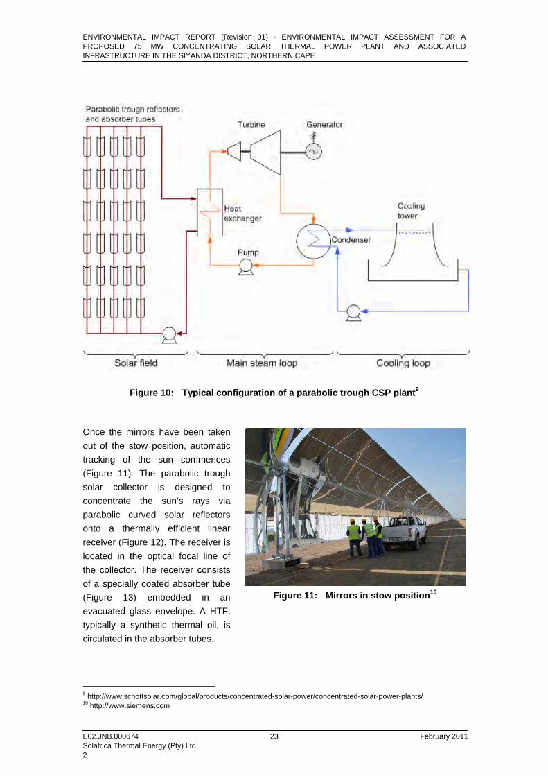
Figure 10: Typical configuration of a parabolic trough CSP plant9 Once the mirrors have been taken out of the stow position, automatic tracking of the sun commences (Figure 11). The parabolic trough solar collector is designed to concentrate the sun’s rays via parabolic curved solar reflectors onto a thermally efficient linear receiver (Figure 12). The receiver is located in the optical focal line of the collector. The receiver consists of a specially coated absorber tube (Figure 13) embedded in an evacuated glass envelope. A HTF, typically a synthetic thermal oil, is circulated in the absorber tubes.
9 http://www.schottsolar.com/global/products/concentrated-solar-power/concentrated-solar-power-plants/ 10 http://www.siemens.com
Figure 11: Mirrors in stow position10

ENVIRONMENTAL IMPACT REPORT (Revision 01) - ENVIRONMENTAL IMPACT ASSESSMENT FOR A PROPOSED 75 MW CONCENTRATING SOLAR THERMAL POWER PLANT AND ASSOCIATED INFRASTRUCTURE IN THE SIYANDA DISTRICT, NORTHERN CAPE
E02.JNB.000674 February 2011 Solafrica Thermal Energy (Pty) Ltd 2
24
Figure 12: Photographic illustration of a parabolic trough11
Figure 13: A receiver tube12
The HTF is circulated through the solar field using auxiliary power until the solar plant becomes self sustaining, after which the oil circulation is powered by the electricity generated by the solar plant (Figure 14). The HTF is then heated to approximately 400°C by the sun’s concentrated rays and subsequently circulated using collector pipes through a series of heat exchangers which imparts the collected solar energy to water circulating through the turbine loop. This happens until the temperature of the water side of the system is heated sufficiently to generate steam. The cooled HTF is subsequently pumped back to the central receiver tubes and the cycle is repeated. The heat transfer (exchange) system is a closed system resulting in the re-use of the HTF. Due to wear and tear, the HTF will require replacement, small volumes are continuously bled off with new fluid being introduced into the system. Spent HTF will be stored in small volumes and periodically removed by a third party services provider for disposal at a registered waste management facility. The relevance of waste management activities, listed in terms of the National Environmental Management: Waste Act (No 59 of 1998), to the proposed plant is to be determined once detailed engineering design of the CSP plant has been concluded. Steam is produced in the heat exchangers which act as a boiler. Thermal energy from the heated HTF is transferred to water with the purpose of generating preheated, evaporated and then superheated water (e.g.: 100 bar in Andasol-1, 50 MWe, Spain). The steam is utilised to turn a conventional steam turbine in the power block to generate kinetic energy which is in turn converted to electrical energy. The system has two steam loop cycles which enables the use of any remaining steam within a secondary turbine and generator system. This will enhance the system and optimise electricity generation.
11 http://www.schottsolar.com/global/products/concentrated-solar-power/concentrated-solar-power-plants/ 12 TREE (Transfer Renewable Energy & Efficiency) seminar. (2009). Seminar material. March 18-20 13 http://www.educypedia.be/education/solarenergy.htm
Figure 14: HTF circulation through receiver tube13
Receiver tube
Mirror parabola

ENVIRONMENTAL IMPACT REPORT (Revision 01) - ENVIRONMENTAL IMPACT ASSESSMENT FOR A PROPOSED 75 MW CONCENTRATING SOLAR THERMAL POWER PLANT AND ASSOCIATED INFRASTRUCTURE IN THE SIYANDA DISTRICT, NORTHERN CAPE
E02.JNB.000674 February 2011 Solafrica Thermal Energy (Pty) Ltd 2
25
The remaining steam is then transported to a condenser which cools the steam to form water. After being cooled and condensed by a cooling mechanism the water is returned to the heat exchangers. Figure 15 illustrates the working of a condenser.
Figure 15: An illustration of a condensor
The main function of the cooling loop is to condense steam and cool water so that it can be re-used in the steam cycle loop. The cooling loop can either use water (wet cooling), air (dry cooling), or both (hybrid) as the cooling medium to the main steam loop. A re-circulating (evaporative) cooling, otherwise known as “wet cooling”, method is proposed for the Solafrica CSP plant - this method of cooling is most common for steam cycle power plants. Furthermore evaporative cooling is the most proven and effective cooling technique, however it uses considerable volumes of water compared to air and hybrid cooling methods. Should the DWA deem that insufficient water is available for evaporative cooling (estimated 859 000 m3 of water per year), then dry and hybrid cooling methods will be considered for implementation. Dry and hybrid cooling is more costly and less energy efficient than evaporative cooling, hence the preference for evaporative cooling – refer to Section 3.4.2 for a description of the cooling methods. Once the solar field and the steam loop have achieved critical values below which the plant will not operate, the power generation system becomes self sustaining. At this point the plant is still not connected to the external grid. Control of the alternator speed is governed automatically until the output of the alternator coincides with the grid electricity waveform, at which point the solar plant can be switched into the grid. The characteristics of the CSP output power would conform to the national grid codes. The power plant electrical power output level must achieve a minimum level, typically 20% of the rated output power of the turbine, before it can be switched into the grid. This would normally be determined automatically, with facility for manual intervention. As the sun arcs across the sky, more solar energy than would be required to run the plant at nameplate capacity is incident on the solar plant. If the plant output is limited by its producer licence, the collection of excess energy is prevented by moving parabolic trough mirrors into stow position until system equilibrium is reached.
ENVIRONMENTAL IMPACT REPORT (Revision 01) - ENVIRONMENTAL IMPACT ASSESSMENT FOR A PROPOSED 75 MW CONCENTRATING SOLAR THERMAL POWER PLANT AND ASSOCIATED INFRASTRUCTURE IN THE SIYANDA DISTRICT, NORTHERN CAPE
E02.JNB.000674 February 2011 Solafrica Thermal Energy (Pty) Ltd 2
26
As the sun sinks at the end of the day, so the collected energy levels decline. The solar plant can stay connected to the grid until the critical turbine power output level is achieved, at which point the solar plant is disconnected from the grid, either manually of by the automated control system. Once disconnected from the grid, the power block and solar fields are shut down. The solar plant is also designed to incorporate thermal heat storage facilities. Heat storage allows a CSP plant to produce electricity at night and on overcast days. This allows the use of solar power for baseload generation as well as peak power generation. Additionally, the use of the generator is higher which reduces cost. For thermal storage, heat is transferred to a thermal storage medium in an insulated reservoir during the day, and withdrawn for power generation at night. The likely thermal storage medium to be used would be molten salts. Molten salt is used in solar power tower systems because it is liquid at atmosphere pressure, it provides an efficient, low-cost medium in which to store thermal energy, its operating temperatures are compatible with high-pressure and high-temperature steam turbines, and it is non-flammable and nontoxic. The mirrors require periodic cleaning, varying typically between fortnightly to weekly, depending on the local conditions which affect the rate of dust deposition on the mirrors. Cleaning of the mirrors is done using dedicated high pressure cleaning equipment, with demineralised water as the cleaning medium. It is crucial that the cleaning water be pure, to avoid abrasion of the front surfaces of the mirrors using the high pressure cleaning equipment. As the plant is shut down at night, the mirror cleaning can be done at night, to maximise plant availability. Alternatively, a loop of the solar field can be moved to the stow position and cleaned, during the day. Maintenance of the equipment and system comprising the power block would be subject to typical conventional steam turbine maintenance regimes. The downtime required for maintenance of the Power Generating System (GPS) would be similar to that required for conventional fossil fired power stations. 2.4.2 Turbine and Generator The steam turbine will be a tandem-compound reheat condensing unit with the high-speed/high-pressure section connected by a speed reduction gear to a single-flow-single-casing low pressure reheat section. A single turbine capable of the mechanical input required for a net generator power output of 75 MW will be included in the Power Block. This configuration will have a length, width, and height of 45m, 25m, and 13m respectively. The turbine has two rotors (high and low pressure) connected to one another through a speed reduction gear and to the generator rotor with a solid bolted coupling. The steam turbine will be connected to a high-pressure steam inlet (supplying working steam from the steam generator) and a steam outlet (transferring spent steam to the cooling system and heat recovery system for re-heating). The turbine will also be connected, via a common axial shaft, to a single generator to which it supplies the input power that is converted to electricity.
ENVIRONMENTAL IMPACT REPORT (Revision 01) - ENVIRONMENTAL IMPACT ASSESSMENT FOR A PROPOSED 75 MW CONCENTRATING SOLAR THERMAL POWER PLANT AND ASSOCIATED INFRASTRUCTURE IN THE SIYANDA DISTRICT, NORTHERN CAPE
E02.JNB.000674 February 2011 Solafrica Thermal Energy (Pty) Ltd 2
27
2.4.3 Heat Exchanging and Cooling The cooling system proposed by Solafrica for the plant will comprise of an evaporative cooling tower of the induced draught type with a multi-cell design (4 cells in total), each cell requiring a heat exchanger (therefore 4 heat exchangers). The cooling tower will comprise of four concurrent flow cells of lineal disposition having a total length, width, and height of 70m, 22m, and 20m respectively. Three cooling methods will be investigated by Solafrica. The cooling methods are wet, dry and hybrid respectively. Each of the proposed cooling methods will be discussed in more detail in sections 2.4.3.1 to 2.4.3.4. 2.4.3.1 Wet Cooling
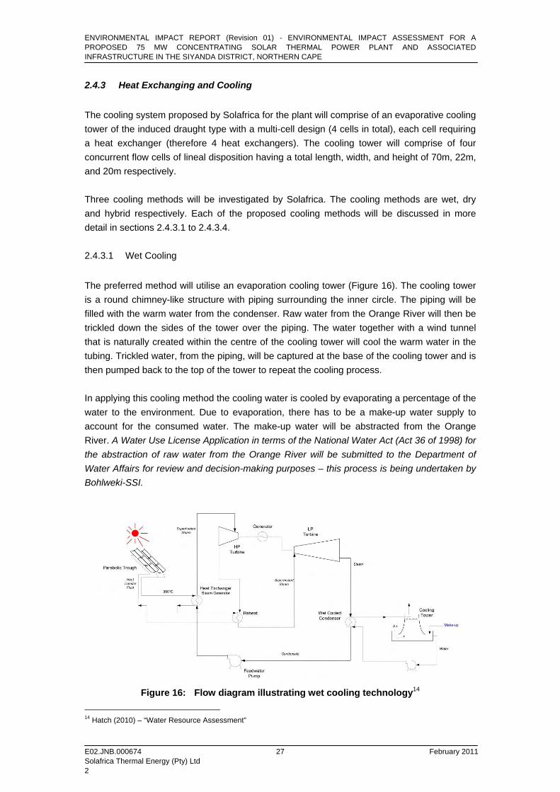
The preferred method will utilise an evaporation cooling tower (Figure 16). The cooling tower is a round chimney-like structure with piping surrounding the inner circle. The piping will be filled with the warm water from the condenser. Raw water from the Orange River will then be trickled down the sides of the tower over the piping. The water together with a wind tunnel that is naturally created within the centre of the cooling tower will cool the warm water in the tubing. Trickled water, from the piping, will be captured at the base of the cooling tower and is then pumped back to the top of the tower to repeat the cooling process. In applying this cooling method the cooling water is cooled by evaporating a percentage of the water to the environment. Due to evaporation, there has to be a make-up water supply to account for the consumed water. The make-up water will be abstracted from the Orange River. A Water Use License Application in terms of the National Water Act (Act 36 of 1998) for the abstraction of raw water from the Orange River will be submitted to the Department of Water Affairs for review and decision-making purposes – this process is being undertaken by Bohlweki-SSI.
Figure 16: Flow diagram illustrating wet cooling technology14
14 Hatch (2010) – “Water Resource Assessment”
ENVIRONMENTAL IMPACT REPORT (Revision 01) - ENVIRONMENTAL IMPACT ASSESSMENT FOR A PROPOSED 75 MW CONCENTRATING SOLAR THERMAL POWER PLANT AND ASSOCIATED INFRASTRUCTURE IN THE SIYANDA DISTRICT, NORTHERN CAPE
E02.JNB.000674 February 2011 Solafrica Thermal Energy (Pty) Ltd 2
28
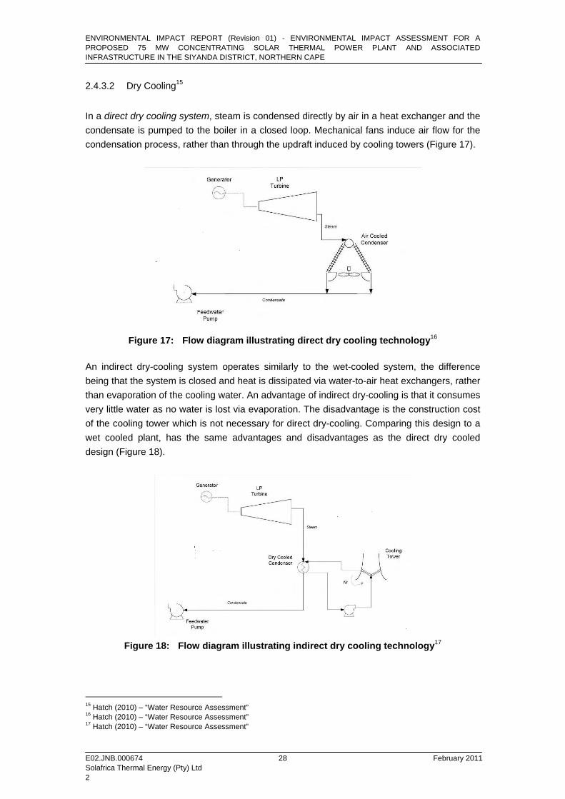
2.4.3.2 Dry Cooling15
In a direct dry cooling system, steam is condensed directly by air in a heat exchanger and the condensate is pumped to the boiler in a closed loop. Mechanical fans induce air flow for the condensation process, rather than through the updraft induced by cooling towers (Figure 17).
Figure 17: Flow diagram illustrating direct dry cooling technology16
An indirect dry-cooling system operates similarly to the wet-cooled system, the difference being that the system is closed and heat is dissipated via water-to-air heat exchangers, rather than evaporation of the cooling water. An advantage of indirect dry-cooling is that it consumes very little water as no water is lost via evaporation. The disadvantage is the construction cost of the cooling tower which is not necessary for direct dry-cooling. Comparing this design to a wet cooled plant, has the same advantages and disadvantages as the direct dry cooled design (Figure 18).
Figure 18: Flow diagram illustrating indirect dry cooling technology17
15 Hatch (2010) – “Water Resource Assessment” 16 Hatch (2010) – “Water Resource Assessment” 17 Hatch (2010) – “Water Resource Assessment”
ENVIRONMENTAL IMPACT REPORT (Revision 01) - ENVIRONMENTAL IMPACT ASSESSMENT FOR A PROPOSED 75 MW CONCENTRATING SOLAR THERMAL POWER PLANT AND ASSOCIATED INFRASTRUCTURE IN THE SIYANDA DISTRICT, NORTHERN CAPE
E02.JNB.000674 February 2011 Solafrica Thermal Energy (Pty) Ltd 2
29
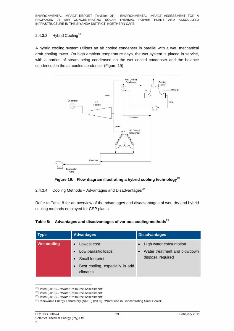
2.4.3.3 Hybrid Cooling18
A hybrid cooling system utilises an air cooled condenser in parallel with a wet, mechanical draft cooling tower. On high ambient temperature days, the wet system is placed in service, with a portion of steam being condensed on the wet cooled condenser and the balance condensed in the air cooled condenser (Figure 19).
Figure 19: Flow diagram illustrating a hybrid cooling technology19
2.4.3.4 Cooling Methods – Advantages and Disadvantages20
Refer to Table 8 for an overview of the advantages and disadvantages of wet, dry and hybrid cooling methods employed for CSP plants.
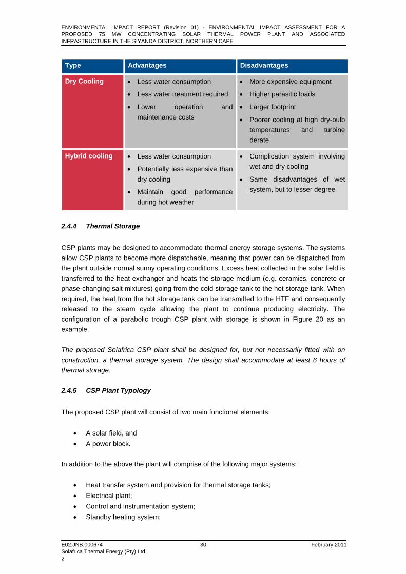
Table 8: Advantages and disadvantages of various cooling methods21
Type Advantages Disadvantages
Wet cooling • Lowest cost
• Low parasitic loads
• Small footprint
• Best cooling, especially in arid climates
• High water consumption
• Water treatment and blowdown disposal required
18 Hatch (2010) – “Water Resource Assessment” 19 Hatch (2010) – “Water Resource Assessment” 20 Hatch (2010) – “Water Resource Assessment” 21 Renewable Energy Laboratory (NREL) (2009), “Water use in Concentrating Solar Power”
ENVIRONMENTAL IMPACT REPORT (Revision 01) - ENVIRONMENTAL IMPACT ASSESSMENT FOR A PROPOSED 75 MW CONCENTRATING SOLAR THERMAL POWER PLANT AND ASSOCIATED INFRASTRUCTURE IN THE SIYANDA DISTRICT, NORTHERN CAPE
E02.JNB.000674 February 2011 Solafrica Thermal Energy (Pty) Ltd 2
30
Type Advantages Disadvantages
Dry Cooling • Less water consumption
• Less water treatment required
• Lower operation and maintenance costs
• More expensive equipment
• Higher parasitic loads
• Larger footprint
• Poorer cooling at high dry-bulb temperatures and turbine derate
Hybrid cooling • Less water consumption
• Potentially less expensive than dry cooling
• Maintain good performance during hot weather
• Complication system involving wet and dry cooling
• Same disadvantages of wet system, but to lesser degree
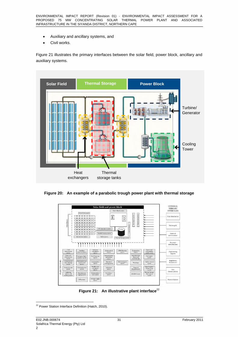
2.4.4 Thermal Storage CSP plants may be designed to accommodate thermal energy storage systems. The systems allow CSP plants to become more dispatchable, meaning that power can be dispatched from the plant outside normal sunny operating conditions. Excess heat collected in the solar field is transferred to the heat exchanger and heats the storage medium (e.g. ceramics, concrete or phase-changing salt mixtures) going from the cold storage tank to the hot storage tank. When required, the heat from the hot storage tank can be transmitted to the HTF and consequently released to the steam cycle allowing the plant to continue producing electricity. The configuration of a parabolic trough CSP plant with storage is shown in Figure 20 as an example. The proposed Solafrica CSP plant shall be designed for, but not necessarily fitted with on construction, a thermal storage system. The design shall accommodate at least 6 hours of thermal storage. 2.4.5 CSP Plant Typology The proposed CSP plant will consist of two main functional elements:
• A solar field, and • A power block.
In addition to the above the plant will comprise of the following major systems:
• Heat transfer system and provision for thermal storage tanks; • Electrical plant; • Control and instrumentation system; • Standby heating system;
ENVIRONMENTAL IMPACT REPORT (Revision 01) - ENVIRONMENTAL IMPACT ASSESSMENT FOR A PROPOSED 75 MW CONCENTRATING SOLAR THERMAL POWER PLANT AND ASSOCIATED INFRASTRUCTURE IN THE SIYANDA DISTRICT, NORTHERN CAPE
E02.JNB.000674 February 2011 Solafrica Thermal Energy (Pty) Ltd 2
31
• Auxiliary and ancillary systems, and • Civil works.
Figure 21 illustrates the primary interfaces between the solar field, power block, ancillary and auxiliary systems.
Figure 20: An example of a parabolic trough power plant with thermal storage
Figure 21: An illustrative plant interface22
22 Power Station Interface Definition (Hatch, 2010).
Thermal storage tanks
Heat exchangers
Solar Field Power Block
Turbine/ Generator
Cooling Tower
Thermal Storage
ENVIRONMENTAL IMPACT REPORT (Revision 01) - ENVIRONMENTAL IMPACT ASSESSMENT FOR A PROPOSED 75 MW CONCENTRATING SOLAR THERMAL POWER PLANT AND ASSOCIATED INFRASTRUCTURE IN THE SIYANDA DISTRICT, NORTHERN CAPE
E02.JNB.000674 February 2011 Solafrica Thermal Energy (Pty) Ltd 2
32
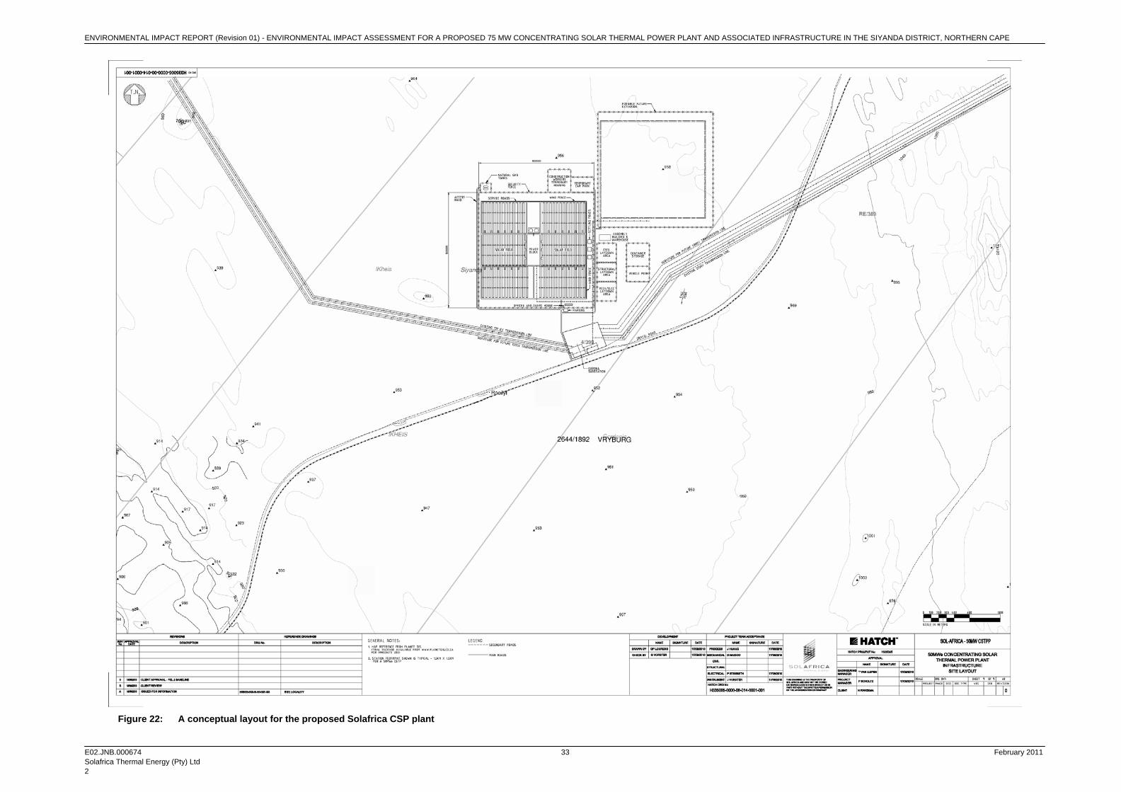
Figure 22 depicts the conceptual layout plan for the proposed Solafrica CSP plant – the final location of the plant will be determined once a detailed geotechnical assessment of the preferred portion of Bokpoort has been undertaken. A final layout plan indicating the CSP plant will be submitted to the DEA once such details have been finalised. 2.4.6 CSP Plant Interfaces 2.4.6.1 Civil Works and Infrastructure
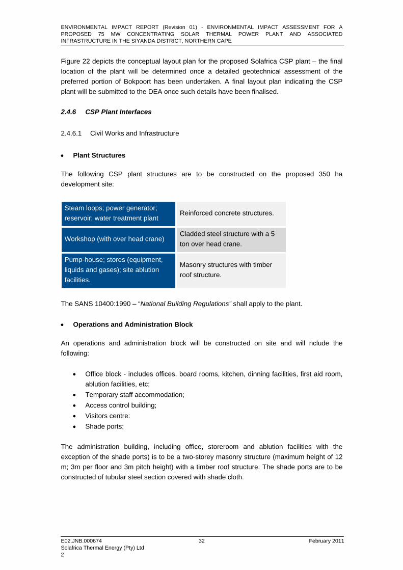
• Plant Structures The following CSP plant structures are to be constructed on the proposed 350 ha development site:
Steam loops; power generator; reservoir; water treatment plant
Reinforced concrete structures.
Workshop (with over head crane) Cladded steel structure with a 5 ton over head crane.
Pump-house; stores (equipment, liquids and gases); site ablution facilities.
Masonry structures with timber roof structure.
The SANS 10400:1990 – “National Building Regulations” shall apply to the plant. • Operations and Administration Block An operations and administration block will be constructed on site and will nclude the following:
• Office block - includes offices, board rooms, kitchen, dinning facilities, first aid room, ablution facilities, etc;
• Temporary staff accommodation; • Access control building; • Visitors centre: • Shade ports;
The administration building, including office, storeroom and ablution facilities with the exception of the shade ports) is to be a two-storey masonry structure (maximum height of 12 m; 3m per floor and 3m pitch height) with a timber roof structure. The shade ports are to be constructed of tubular steel section covered with shade cloth.
ENVIRONMENTAL IMPACT REPORT (Revision 01) - ENVIRONMENTAL IMPACT ASSESSMENT FOR A PROPOSED 75 MW CONCENTRATING SOLAR THERMAL POWER PLANT AND ASSOCIATED INFRASTRUCTURE IN THE SIYANDA DISTRICT, NORTHERN CAPE
E02.JNB.000674 February 2011 Solafrica Thermal Energy (Pty) Ltd 2
33
Figure 22: A conceptual layout for the proposed Solafrica CSP plant
ENVIRONMENTAL IMPACT REPORT (Revision 01) - ENVIRONMENTAL IMPACT ASSESSMENT FOR A PROPOSED 75 MW CONCENTRATING SOLAR THERMAL POWER PLANT AND ASSOCIATED INFRASTRUCTURE IN THE SIYANDA DISTRICT, NORTHERN CAPE
E02.JNB.000674 February 2011 Solafrica Thermal Energy (Pty) Ltd 2
34
2.4.6.2 Vehicle Access / Service Roads
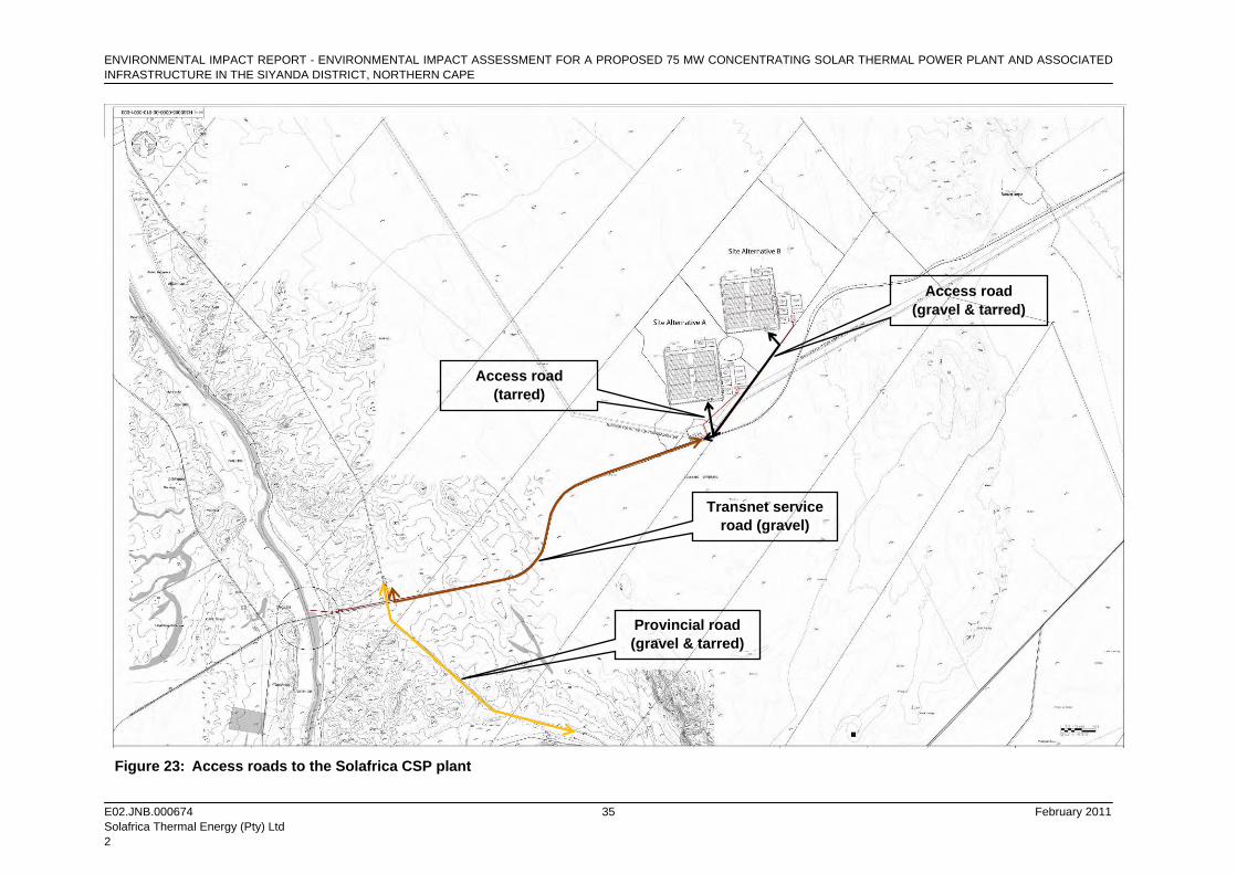
New vehicle access/service roads and upgrades to existing roads (within in the local road network) will be required by Solafrica for the construction and operational phases of the proposed CSP plant in order to allow or improve accessibility to the proposed site. Existing roads (Transnet service and Northern Cape Provincial roads) will be upgraded according to the technical specifications required for heavy hauls/abnormal loads. It is not envisaged that such roads require broadening – the upgrade will likely entail the levelling of sections of these roads. A new access road is to be constructed connecting the CSP Plant with the Transnet service road across the Farm Bokpoort. In the case of plant location alternatives A, the road will extend 1000 m to the plant, as depicted in Figure 23, having a road width of 8 m. The road will be fully tarred and constructed to meet the required standards for large construction vehicles. For the case of plant location alternative B, a gravel road of length 3200m and width 8m will be constructed from the Transnet servitude exit from Farm Bokpoort along the farm boundary to a point adjacent to the plant location B. A fully tarred road of length 667m and width 8m will be constructed to connect the gravel road with the plant at location B. The gravel and tar portions of the road will be constructed to meet the required standards for large construction vehicles. The main access roads and parking areas on the plant are to be paved and service roads (on the plant and security road) are to be unpaved. 2.4.6.3 Electricity Supply/Connection Infrastructure
For the plant to supply auxiliary electricity to Eskom’s local electricity distribution network, it is intended by Solafrica to construct a sub-transmission (overhead) powerline, with a nominal voltage of 132 kV, to allow for connection to Eskom’s Garona substation (located on the Farm Bokpoort). Power generated by the CSP plant’s steam turbine generator will be stepped up by way of on-site transformers from 11-12 kV to 132 kV, to match the rating of the Garona distribution line. The Garona substation forms part of the national transmission network which will enable the supply of electricity to Eskom’s distribution network23 running from the Garona substation to the Upington region in addition to the transmission network24 running from Garona substation to the Ferrum substation (near Sishen). The 132 kV powerline (height = 25m) requires a 32m wide servitude (or 16m to each side measured from the powerline’s centreline).
23 Electrical power network where the nominal voltage is equal or less than 132kV. 24 Electrical power network where the nominal voltage exceeds 132kV.
ENVIRONMENTAL IMPACT REPORT - ENVIRONMENTAL IMPACT ASSESSMENT FOR A PROPOSED 75 MW CONCENTRATING SOLAR THERMAL POWER PLANT AND ASSOCIATED INFRASTRUCTURE IN THE SIYANDA DISTRICT, NORTHERN CAPE
E02.JNB.000674 February 2011 Solafrica Thermal Energy (Pty) Ltd 2
35
Figure 23: Access roads to the Solafrica CSP plant
Access road (gravel & tarred)
Access road (tarred)
Transnet service road (gravel)
Provincial road (gravel & tarred)
ENVIRONMENTAL IMPACT REPORT - ENVIRONMENTAL IMPACT ASSESSMENT FOR A PROPOSED 75 MW CONCENTRATING SOLAR THERMAL POWER PLANT AND ASSOCIATED INFRASTRUCTURE IN THE SIYANDA DISTRICT, NORTHERN CAPE
E02.JNB.000674 February 2011 Solafrica Thermal Energy (Pty) Ltd 2
36
The design of overhead power lines shall comply with the requirements of the following:
• SANS 10280:2001 - “Overhead power lines for conditions prevailing in South Africa”; • SANS 10280-1:2008 / NRS 041-1:2008 - “Overhead power lines for conditions
prevailing in South Africa Part 1: Safety”, and • Occupational Health and Safety Act – Electrical Machinery Regulations (March 2005).
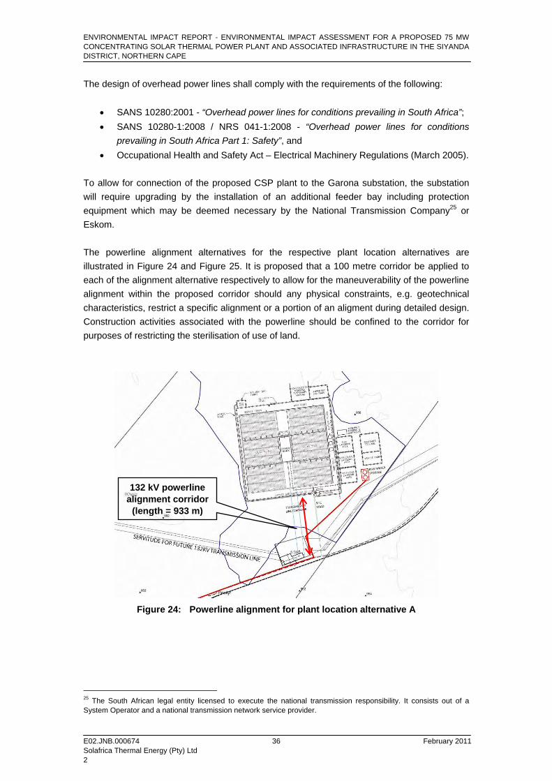
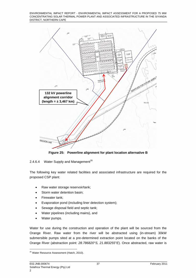
To allow for connection of the proposed CSP plant to the Garona substation, the substation will require upgrading by the installation of an additional feeder bay including protection equipment which may be deemed necessary by the National Transmission Company25 or Eskom. The powerline alignment alternatives for the respective plant location alternatives are illustrated in Figure 24 and Figure 25. It is proposed that a 100 metre corridor be applied to each of the alignment alternative respectively to allow for the maneuverability of the powerline alignment within the proposed corridor should any physical constraints, e.g. geotechnical characteristics, restrict a specific alignment or a portion of an aligment during detailed design. Construction activities associated with the powerline should be confined to the corridor for purposes of restricting the sterilisation of use of land.
Figure 24: Powerline alignment for plant location alternative A
25 The South African legal entity licensed to execute the national transmission responsibility. It consists out of a System Operator and a national transmission network service provider.
132 kV powerline alignment corridor
(length = 933 m)
ENVIRONMENTAL IMPACT REPORT - ENVIRONMENTAL IMPACT ASSESSMENT FOR A PROPOSED 75 MW CONCENTRATING SOLAR THERMAL POWER PLANT AND ASSOCIATED INFRASTRUCTURE IN THE SIYANDA DISTRICT, NORTHERN CAPE
E02.JNB.000674 February 2011 Solafrica Thermal Energy (Pty) Ltd 2
37
Figure 25: Powerline alignment for plant location alternative B
2.4.6.4 Water Supply and Management26
The following key water related facilities and associated infrastructure are required for the proposed CSP plant:
• Raw water storage reservoir/tank; • Storm water detention basin; • Firewater tank; • Evaporation pond (including liner detection system); • Sewage disposal field and septic tank; • Water pipelines (including mains), and • Water pumps.
Water for use during the construction and operation of the plant will be sourced from the Orange River. Raw water from the river will be abstracted using (in-stream) 30kW submersible pumps sited at a pre-determined extraction point located on the banks of the Orange River (abstraction point: 28.786820°S, 21.883255°E). Once abstracted, raw water is
26 Water Resource Assessment (Hatch, 2010).
132 kV powerline alignment corridor
(length = ± 3,467 km)
ENVIRONMENTAL IMPACT REPORT - ENVIRONMENTAL IMPACT ASSESSMENT FOR A PROPOSED 75 MW CONCENTRATING SOLAR THERMAL POWER PLANT AND ASSOCIATED INFRASTRUCTURE IN THE SIYANDA DISTRICT, NORTHERN CAPE
E02.JNB.000674 February 2011 Solafrica Thermal Energy (Pty) Ltd 2
38
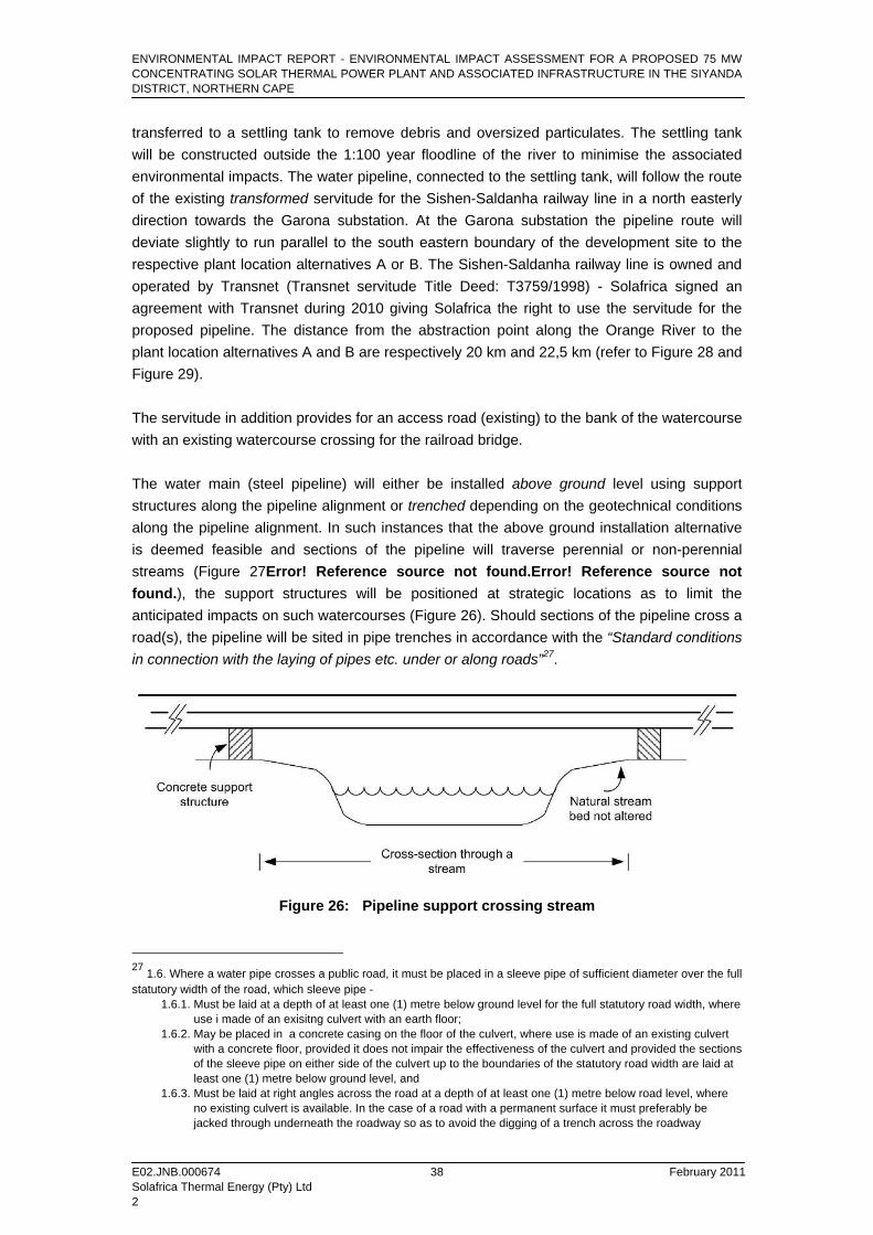
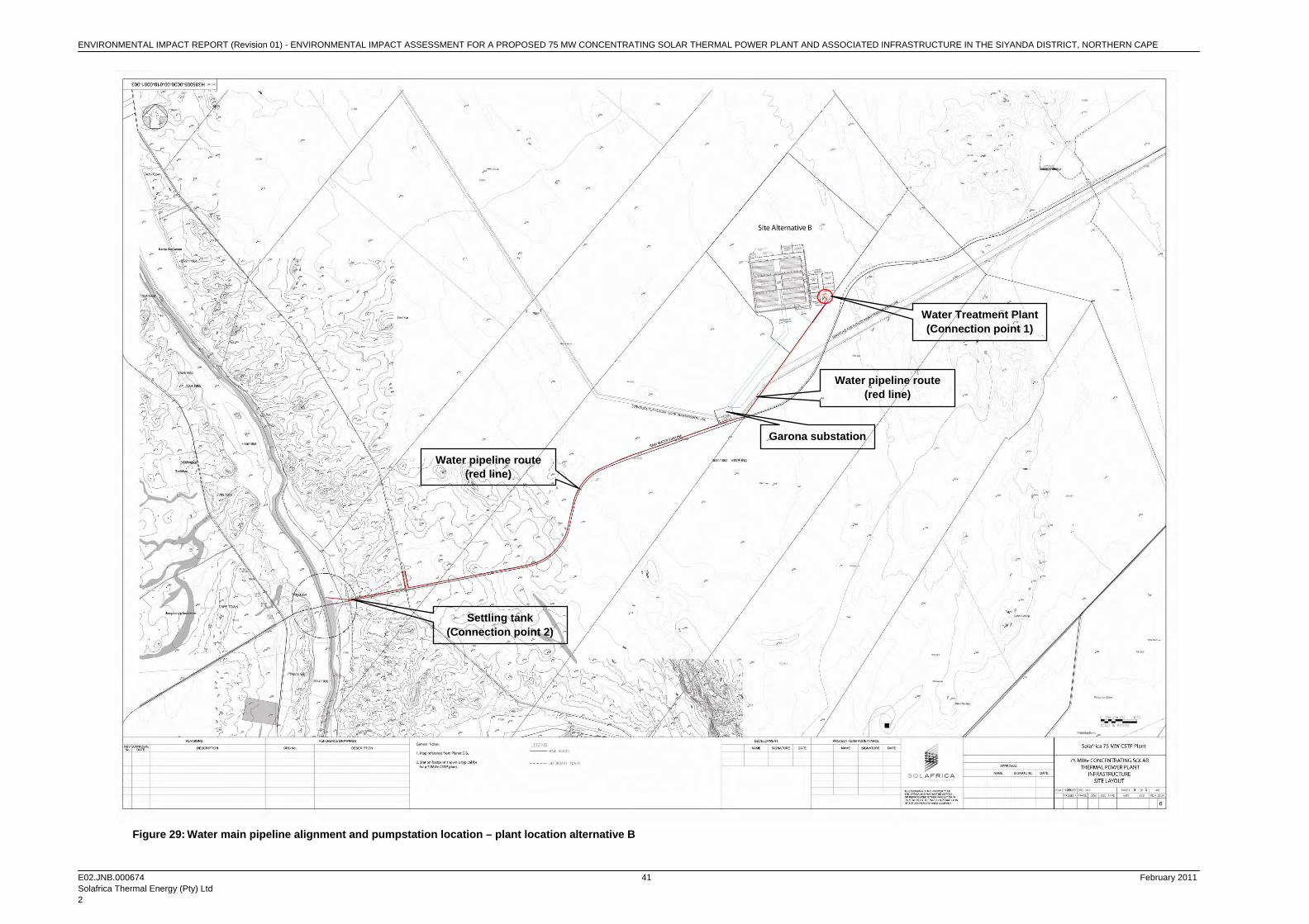
transferred to a settling tank to remove debris and oversized particulates. The settling tank will be constructed outside the 1:100 year floodline of the river to minimise the associated environmental impacts. The water pipeline, connected to the settling tank, will follow the route of the existing transformed servitude for the Sishen-Saldanha railway line in a north easterly direction towards the Garona substation. At the Garona substation the pipeline route will deviate slightly to run parallel to the south eastern boundary of the development site to the respective plant location alternatives A or B. The Sishen-Saldanha railway line is owned and operated by Transnet (Transnet servitude Title Deed: T3759/1998) - Solafrica signed an agreement with Transnet during 2010 giving Solafrica the right to use the servitude for the proposed pipeline. The distance from the abstraction point along the Orange River to the plant location alternatives A and B are respectively 20 km and 22,5 km (refer to Figure 28 and Figure 29). The servitude in addition provides for an access road (existing) to the bank of the watercourse with an existing watercourse crossing for the railroad bridge. The water main (steel pipeline) will either be installed above ground level using support structures along the pipeline alignment or trenched depending on the geotechnical conditions along the pipeline alignment. In such instances that the above ground installation alternative is deemed feasible and sections of the pipeline will traverse perennial or non-perennial streams (Figure 27Error! Reference source not found.Error! Reference source not found.), the support structures will be positioned at strategic locations as to limit the anticipated impacts on such watercourses (Figure 26). Should sections of the pipeline cross a road(s), the pipeline will be sited in pipe trenches in accordance with the “Standard conditions in connection with the laying of pipes etc. under or along roads”27.
Figure 26: Pipeline support crossing stream
27 1.6. Where a water pipe crosses a public road, it must be placed in a sleeve pipe of sufficient diameter over the full statutory width of the road, which sleeve pipe -
1.6.1. Must be laid at a depth of at least one (1) metre below ground level for the full statutory road width, where use i made of an exisitng culvert with an earth floor; 1.6.2. May be placed in a concrete casing on the floor of the culvert, where use is made of an existing culvert with a concrete floor, provided it does not impair the effectiveness of the culvert and provided the sections of the sleeve pipe on either side of the culvert up to the boundaries of the statutory road width are laid at least one (1) metre below ground level, and 1.6.3. Must be laid at right angles across the road at a depth of at least one (1) metre below road level, where no existing culvert is available. In the case of a road with a permanent surface it must preferably be jacked through underneath the roadway so as to avoid the digging of a trench across the roadway
ENVIRONMENTAL IMPACT REPORT - ENVIRONMENTAL IMPACT ASSESSMENT FOR A PROPOSED 75 MW CONCENTRATING SOLAR THERMAL POWER PLANT AND ASSOCIATED INFRASTRUCTURE IN THE SIYANDA DISTRICT, NORTHERN CAPE
E02.JNB.000674 February 2011 Solafrica Thermal Energy (Pty) Ltd 2
39
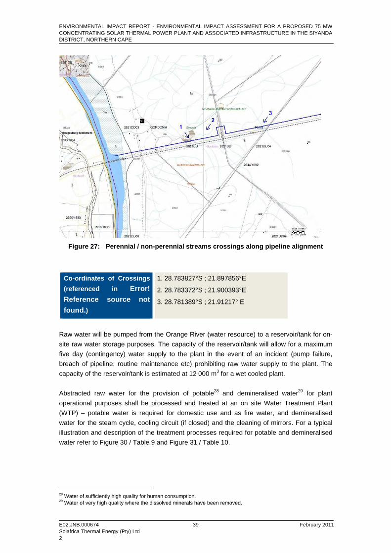
Figure 27: Perennial / non-perennial streams crossings along pipeline alignment
Co-ordinates of Crossings (referenced in Error! Reference source not found.)
1. 28.783827°S ; 21.897856°E
2. 28.783372°S ; 21.900393°E
3. 28.781389°S ; 21.91217° E
Raw water will be pumped from the Orange River (water resource) to a reservoir/tank for on-site raw water storage purposes. The capacity of the reservoir/tank will allow for a maximum five day (contingency) water supply to the plant in the event of an incident (pump failure, breach of pipeline, routine maintenance etc) prohibiting raw water supply to the plant. The capacity of the reservoir/tank is estimated at 12 000 m3 for a wet cooled plant. Abstracted raw water for the provision of potable28 and demineralised water29 for plant operational purposes shall be processed and treated at an on site Water Treatment Plant (WTP) – potable water is required for domestic use and as fire water, and demineralised water for the steam cycle, cooling circuit (if closed) and the cleaning of mirrors. For a typical illustration and description of the treatment processes required for potable and demineralised water refer to Figure 30 / Table 9 and Figure 31 / Table 10.
28 Water of sufficiently high quality for human consumption. 29 Water of very high quality where the dissolved minerals have been removed.

ENVIRONMENTAL IMPACT REPORT (Revision 01) - ENVIRONMENTAL IMPACT ASSESSMENT FOR A PROPOSED 75 MW CONCENTRATING SOLAR THERMAL POWER PLANT AND ASSOCIATED INFRASTRUCTURE IN THE SIYANDA DISTRICT, NORTHERN CAPE
E02.JNB.000674 February 2011 Solafrica Thermal Energy (Pty) Ltd 2
40
Figure 28: Water main pipeline alignment and pumpstation location – plant location alternative A
Water Treatment Plant (Connection point 1)
Settling tank (Connection point 2)
Water pipeline route (red line)
Water pipeline route (red line)
Garona substation
ENVIRONMENTAL IMPACT REPORT (Revision 01) - ENVIRONMENTAL IMPACT ASSESSMENT FOR A PROPOSED 75 MW CONCENTRATING SOLAR THERMAL POWER PLANT AND ASSOCIATED INFRASTRUCTURE IN THE SIYANDA DISTRICT, NORTHERN CAPE
E02.JNB.000674 February 2011 Solafrica Thermal Energy (Pty) Ltd 2
41
Figure 29: Water main pipeline alignment and pumpstation location – plant location alternative B
Water Treatment Plant (Connection point 1)
Settling tank (Connection point 2)
Water pipeline route (red line)
Water pipeline route (red line)
Garona substation

ENVIRONMENTAL IMPACT REPORT (Revision 01) - ENVIRONMENTAL IMPACT ASSESSMENT FOR A PROPOSED 75 MW CONCENTRATING SOLAR THERMAL POWER PLANT AND ASSOCIATED INFRASTRUCTURE IN THE SIYANDA DISTRICT, NORTHERN CAPE
E02.JNB.000674 February 2011 Solafrica Thermal Energy (Pty) Ltd 2
42
Figure 30: Typical potable water treatment process
Table 9: Description of the potable water treatment process
Process Purpose
Debris Settling (Step 1) Settle out twigs, rocks and sand pumped from the river. Chemical agent can be added in this early part of the process to reduce the amount of later disinfectants and is used to control taste and odours, remove colour and control biological growth.
Coagulation (Step 2) Charged particulates in the water combine with the chemical agent ions, neutralizing the charges. The neutral particulates combine to form larger particles, and finally settle down.
Flocculation (Step 3) Polymer flocculants are used to bind suspended solid particles.
Sedimentation (Step 4) A settling tank is used to let the flocculated or coagulated particles to settle out. The sludge must occasionally be removed.
Filtration (Step 5) Removing solids from the water by passing it through a porous medium. Solids can be removed by backwashing.
Disinfection / Chemical Treatments (Step 6)
To kill unwanted micro organisms in the water.
ENVIRONMENTAL IMPACT REPORT (Revision 01) - ENVIRONMENTAL IMPACT ASSESSMENT FOR A PROPOSED 75 MW CONCENTRATING SOLAR THERMAL POWER PLANT AND ASSOCIATED INFRASTRUCTURE IN THE SIYANDA DISTRICT, NORTHERN CAPE
E02.JNB.000674 February 2011 Solafrica Thermal Energy (Pty) Ltd 2
43
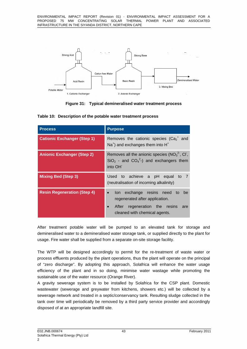
Figure 31: Typical demineralised water treatment process
Table 10: Description of the potable water treatment process
Process Purpose
Cationic Exchanger (Step 1) Removes the cationic species (Ca2+ and
Na+) and exchanges them into H+
Anionic Exchanger (Step 2) Removes all the anionic species (NO32-, Cl-,
SiO2 - and CO42-) and exchangers them
into OH-
Mixing Bed (Step 3) Used to achieve a pH equal to 7 (neutralisation of incoming alkalinity)
Resin Regeneration (Step 4) • Ion exchange resins need to be regenerated after application.
• After regeneration the resins are cleaned with chemical agents.
After treatment potable water will be pumped to an elevated tank for storage and demineralised water to a demineralised water storage tank, or supplied directly to the plant for usage. Fire water shall be supplied from a separate on-site storage facility. The WTP will be designed accordingly to permit for the re-treatment of waste water or process effluents produced by the plant operations, thus the plant will operate on the principal of “zero discharge”. By adopting this approach, Solafrica will enhance the water usage efficiency of the plant and in so doing, minimise water wastage while promoting the sustainable use of the water resource (Orange River). A gravity sewerage system is to be installed by Solafrica for the CSP plant. Domestic wastewater (sewerage and greywater from kitchens, showers etc.) will be collected by a sewerage network and treated in a septic/conservancy tank. Resulting sludge collected in the tank over time will periodically be removed by a third party service provider and accordingly disposed of at an appropriate landfill site.
ENVIRONMENTAL IMPACT REPORT (Revision 01) - ENVIRONMENTAL IMPACT ASSESSMENT FOR A PROPOSED 75 MW CONCENTRATING SOLAR THERMAL POWER PLANT AND ASSOCIATED INFRASTRUCTURE IN THE SIYANDA DISTRICT, NORTHERN CAPE
E02.JNB.000674 February 2011 Solafrica Thermal Energy (Pty) Ltd 2
44
2.4.6.5 Auxiliary Heating System / Boiler
• Description Back-up gas fired heaters are used to maintain the temperature of the HTF above its freezing point of 12°C. Natural-draft burners are used in a wide range of residential and commercial applications, including gas-fired furnaces, water heaters, cooking ranges, and ovens. However, these burners are somewhat unique in industry. Most burners used in industrial combustion applications are forced or mechanical draft, where the combustion air is supplied to the burner with a fan or blower. In natural-draft burners, the combustion air is induced or drawn into the burner via the suction created by the incoming fuel jets and via the buoyancy forces inside the furnace that create an updraft. Fired heaters are used in the petrochemical and hydrocarbon industries to heat fluids in tubes for further processing. In this type of process, fluids flow through an array of tubes located inside a furnace or heater. The tubes are heated by direct-fired burners. Using tubes to contain the load is somewhat unique compared to the other types of industrial combustion applications.
Process heaters are sometimes referred to as process furnaces or direct-fired heaters. They are heat transfer units designed to heat petroleum products, chemicals, and other liquids and gases flowing through tubes. Typical petroleum fluids include gasoline, naphtha, kerosene, distillate oil, lube oil, gas oil, and light ends. For this plant the heating is done to raise the temperature of the fluid to prevent freezing in the CSP plant. The primary modes of heat transfer in process heaters are radiation and convection. The initial part of the fluid heating is done in the convection section of the furnace, while the latter heating is done in the radiant section. Each section has a bank of tubes in it through which the fluids flow that is being heated. • National Environmental Management: Air Quality Act (Act 39 of 2004) Listed activities and associated minimum emission standards have been issued by the DEA on 24 July 2009 (Government Gazette No 32434). As per the listed activities and minimum emission standards, the following activities, where applicable to the proposed project, would require an Atmospheric Emission Licence to operate:
• All liquid fuels combustion installations used primarily for steam raising or electricity generation, with a design capacity of more than 50 MW heat input per unit, based on the lower calorific value of the fuel used;
• Gas combustion used primarily for steam raising or electricity generation, with a design capacity of more than 50 MW heat input per unit, based on the lower calorific value of the fuel used, and

ENVIRONMENTAL IMPACT REPORT (Revision 01) - ENVIRONMENTAL IMPACT ASSESSMENT FOR A PROPOSED 75 MW CONCENTRATING SOLAR THERMAL POWER PLANT AND ASSOCIATED INFRASTRUCTURE IN THE SIYANDA DISTRICT, NORTHERN CAPE
E02.JNB.000674 February 2011 Solafrica Thermal Energy (Pty) Ltd 2
45
• Petroleum product storage tanks and product transfer facilities, producing more than 100 ton per annum of products; all liquid storage tanks larger than 500 cubic metres cumulative tankage capacity.
In terms of the design capacity (11.5 MW), the proposed boiler would not classify as a listed activity and therefore would not require an Atmospheric Emission Licence to operate. The on-site storage of diesel will also be below the required limit to be classified as a listed activity. 2.4.6.6 Stormwater Management
Stormwater will be collected on-site by a storm water drainage system and temporarily stored in a storm water detention basin before being discharged to the main drainage system. Drainage shall be collected at the lowest point (altitude) of the site. 2.4.6.7 Security
A security fence will be erected along the perimeter of the site with a service road along and perimeter security lighting on the inside of the. 2.4.6.8 Fire protection
Provision shall be made for firebreaks outside the plant perimeter. The firebreak will have a dual purpose:
a) Protecting the plant in the event of a veld fire, and b) Protecting floral and faunal habitats located outside the plant area in the event of a
fire on the CSP plant. 2.4.6.9 Windbreak
A wind fence shall be provided to control the influence of high winds on the solar field. 2.4.6.10 Dangerous Goods Storage
A preliminary investigation was carried out into the sizing of components for the provision of auxiliary power. Boiler capacity (estimated at 11.5 MW) will be included for the co-firing of Light Fuel Oil (LFO) [Diesel] or Liquid Petroleum Gas (LPG) and the heating of the HTF during start-up and anti-freeze conditions. Co-firing will take place at times most optimal in supplementing the thermal power of the sun using fuel up to a maximum of the allowable 15% of power generation (as stated in NERSA’s REFIT conditions). Additional firing will take place during the 4 months of the winter season to maintain a minimum temperature of the HTF.
ENVIRONMENTAL IMPACT REPORT (Revision 01) - ENVIRONMENTAL IMPACT ASSESSMENT FOR A PROPOSED 75 MW CONCENTRATING SOLAR THERMAL POWER PLANT AND ASSOCIATED INFRASTRUCTURE IN THE SIYANDA DISTRICT, NORTHERN CAPE
E02.JNB.000674 February 2011 Solafrica Thermal Energy (Pty) Ltd 2
46
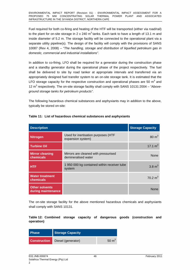
Fuel required for both co-firing and heating of the HTF will be transported (either via road/rail) to the plant for on-site storage in 2 x 240 m3 tanks. Each tank to have a length of 13.1 m and inside diameter of 5.2 m. The storage facility will be connected to the operational plant via a separate utility pipeline(s). The design of the facility will comply with the provisions of SANS 10087 (Rev 4, 2008) – “The handling, storage and distribution of liquefied petroleum gas in domestic, commercial and industrial installations”. In addition to co-firing, LFO shall be required for a generator during the construction phase and a standby generator during the operational phase of the project respectively. The fuel shall be delivered to site by road tanker at appropriate intervals and transferred via an appropriately designed fuel transfer system to an on-site storage tank. It is estimated that the LFO storage capacity for the respective construction and operational phases are 50 m3 and 12 m3 respectively. The on-site storage facility shall comply with SANS 10131:2004 – “Above-ground storage tanks for petroleum products”. The following hazardous chemical substances and asphyxiants may in addition to the above, typically be stored on-site:
Table 11: List of hazardous chemical substances and asphyxiants
Description Storage Capacity
Nitrogen Used for inertisation purposes (HTF expansion system) 80 m3
Turbine Oil 17.1 m3
Mirror cleaning chemicals
Mirrors are cleaned with pressurised demineralised water None
HTF 1 950 000 kg contained within receiver tube system 3.8 m3
Water treatment chemicals 70.2 m3
Other solvents during maintenance None
The on-site storage facility for the above mentioned hazardous chemicals and asphyxiants shall comply with SANS 10131.
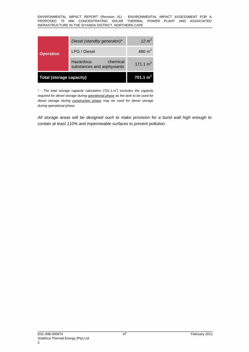
Table 12: Combined storage capacity of dangerous goods (construction and operation)
Phase Storage Capacity
Construction Diesel (generator) 50 m3
ENVIRONMENTAL IMPACT REPORT (Revision 01) - ENVIRONMENTAL IMPACT ASSESSMENT FOR A PROPOSED 75 MW CONCENTRATING SOLAR THERMAL POWER PLANT AND ASSOCIATED INFRASTRUCTURE IN THE SIYANDA DISTRICT, NORTHERN CAPE
E02.JNB.000674 February 2011 Solafrica Thermal Energy (Pty) Ltd 2
47
Operation
Diesel (standby generator)* 12 m3
LPG / Diesel 480 m3
Hazardous chemical substances and asphyxiants 171.1 m3
Total (storage capacity) 701.1 m3
* - The total storage capacity calculation (701.1.m3) excludes the capacity required for diesel storage during operational phase as the tank to be used for diesel storage during construction phase may be used for diesel storage during operational phase.
All storage areas will be designed such to make provision for a bund wall high enough to contain at least 110% and impermeable surfaces to prevent pollution.