Embed Size (px)
Citation preview
MOE-KLTFSE
Lattice Boltzmann for flow and transport phenomena
2. The lattice Boltzmann for porous flow and
transport
Li Chen
XJTU, 2021/03/30
1/66
Mail: [email protected]
Webpage: http://gr.xjtu.edu.cn/web/lichennht08
ResearchID: P-4886-2014
MOE-KLTFSE
o 2.1 Background
o 2.2 Structural characteristics of porous media
o 2.5 Pore-scale simulation: LB for fluid flow
Content
o 2.4 Pore-scale simulation: reconstruction of porous media
o 2.3 Continuum-scale governing equation for porous media
o 2.6 Pore-scale simulation: LB for heat transfer
2/66
MOE-KLTFSE
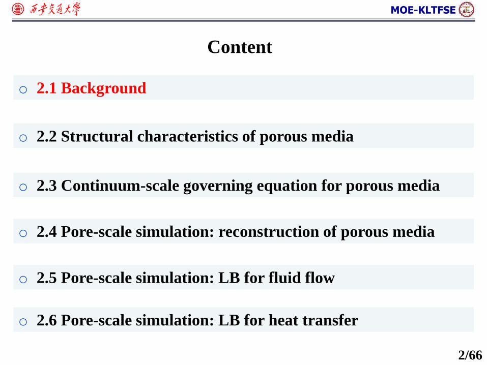
2.1 Examples of porous media
o Natural porous systems: enhanced hydrocarbon and geothermal
energy recovery, CO2 geological sequestration,
o Artificial porous systems: fuel cell, reactor, catalysts, building
material…
CO2
多孔介质内传热传质
3/66
MOE-KLTFSE
o 2.1 Examples of porous media
o 2.2 Structural characteristics of porous media
o 2.5 Pore-scale simulation: LB for fluid flow
Content
o 2.4 Pore-scale simulation: reconstruction of porous media
o 2.3 Continuum-scale governing equation for porous media
o 2.6 Pore-scale simulation: LB for heat transfer
5/66
MOE-KLTFSE
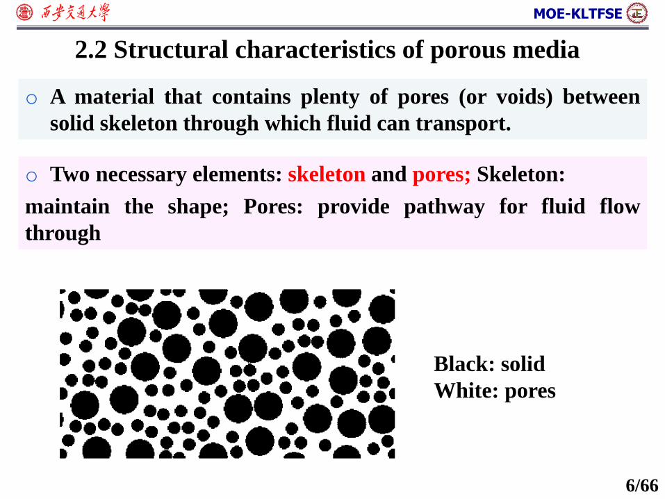
2.2 Structural characteristics of porous media
o A material that contains plenty of pores (or voids) between
solid skeleton through which fluid can transport.
o Two necessary elements: skeleton and pores; Skeleton:
maintain the shape; Pores: provide pathway for fluid flow
through
Black: solid
White: pores
6/66
MOE-KLTFSE
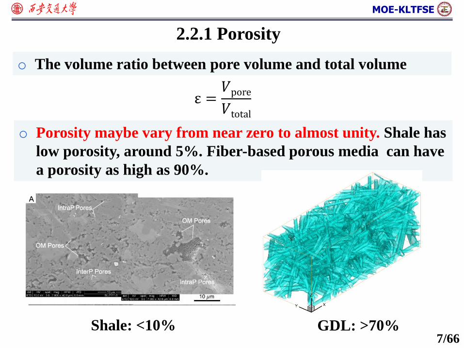
2.2.1 Porosity
o The volume ratio between pore volume and total volume
Shale: <10% GDL: >70%
o Porosity maybe vary from near zero to almost unity. Shale has
low porosity, around 5%. Fiber-based porous media can have
a porosity as high as 90%.
ε =𝑉pore
𝑉total
7/66
MOE-KLTFSE
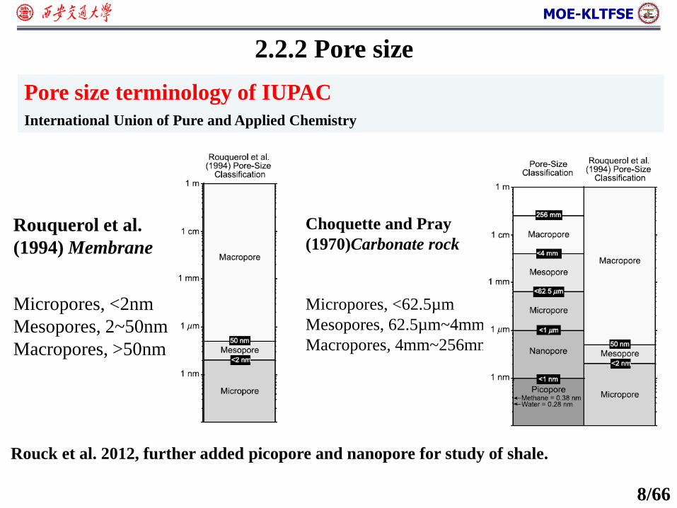
2.2.2 Pore size
Micropores, <2nm
Mesopores, 2~50nm
Macropores, >50nm
Rouquerol et al.
(1994) Membrane
Choquette and Pray
(1970)Carbonate rock
Micropores, <62.5µm
Mesopores, 62.5µm~4mm
Macropores, 4mm~256mm
Pore size terminology of IUPAC
International Union of Pure and Applied Chemistry
Rouck et al. 2012, further added picopore and nanopore for study of shale.
8/66
MOE-KLTFSE
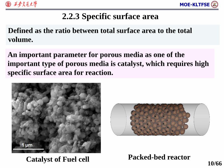
2.2.3 Specific surface area
Defined as the ratio between total surface area to the total
volume.
An important parameter for porous media as one of the
important type of porous media is catalyst, which requires high
specific surface area for reaction.
Catalyst of Fuel cell Packed-bed reactor10/66

MOE-KLTFSE
2.2.4 Tortuosity
Tortuosity: defined as the actual length traveled by a particle to
the length of the media
𝜏 =𝐿𝑖𝐿 𝐿
𝐿𝑖
Tortuosity is thus transport dependent, including flow,
diffusion, heat transfer, electrical conduct, acoustic transport.
For fluid flow it is “hydraulic tortuosity”
For diffusion it is “diffusivity tortuosity”
For electron transport, it is “conductivity tortuosity”
Except for some very simple porous structures, there is no clear
consensus on the relation between these definitions.11/66
MOE-KLTFSE
o 2.1 Examples of porous media
o 2.2 Structural characteristics of porous media
o 2.5 Pore-scale simulation: LB for fluid flow
Content
o 2.4 Pore-scale simulation: reconstruction of porous media
o 2.3 Continuum-scale governing equation for porous media
o 2.6 Pore-scale simulation: LB for heat transfer
12/66
MOE-KLTFSE
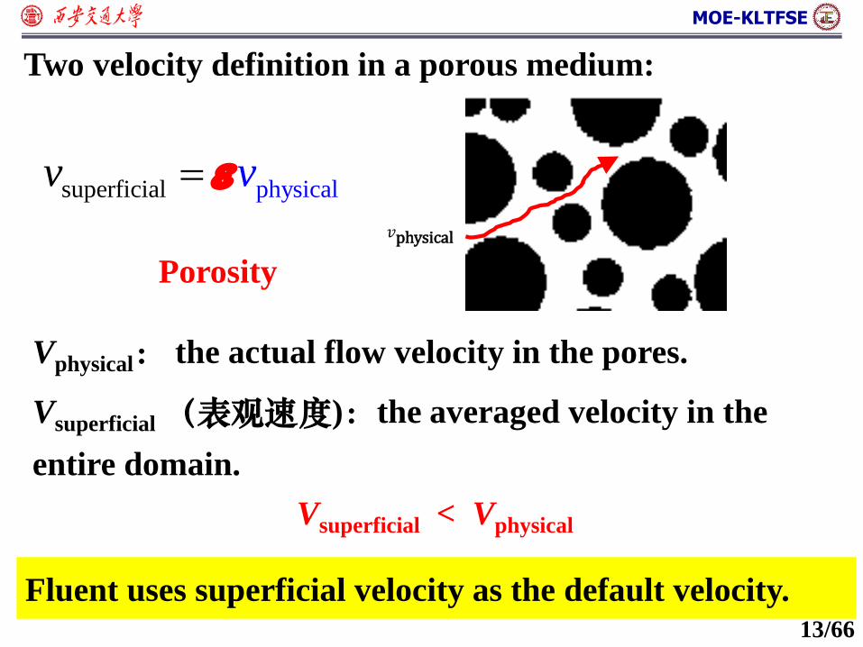
Two velocity definition in a porous medium:
superficial physicalv v
Vphysical: the actual flow velocity in the pores.
𝑣physical
Vsuperficial(表观速度):the averaged velocity in the
entire domain.
Vsuperficial < Vphysical
Porosity
Fluent uses superficial velocity as the default velocity. 13/66
MOE-KLTFSE
superficial 0 u
superficial
superficial superficia
2
l
1( )( ( ) ( )p )u u Fu
- - | |F
k kF u u u
eff
superficial eff
2
eff
(( )(
( )u
p
p
TC
CST T
t
)) +
eff (1 ) s f
Continuum-scale equations for porous flow
14/66
MOE-KLTFSE
o 2.1 Examples of porous media
o 2.2 Structural characteristics of porous media
o 2.5 Pore-scale simulation: LB for fluid flow
Content
o 2.4 Pore-scale simulation: reconstruction of porous media
o 2.3 Continuum-scale governing equation for porous media
o 2.6 Pore-scale simulation: LB for heat transfer
15/66
MOE-KLTFSE
16/66
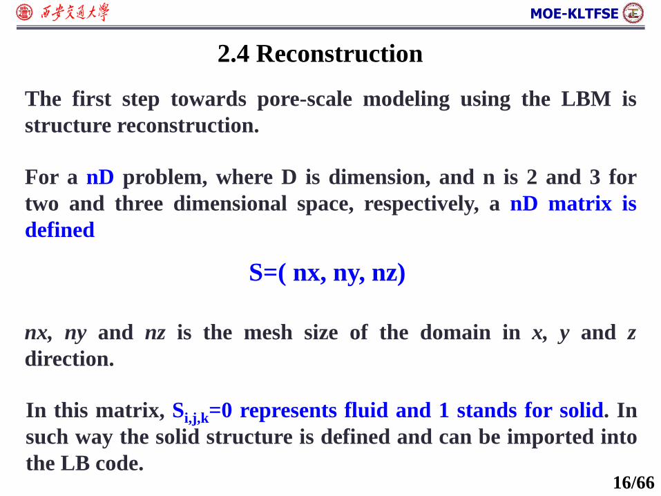
2.4 Reconstruction
The first step towards pore-scale modeling using the LBM is
structure reconstruction.
For a nD problem, where D is dimension, and n is 2 and 3 for
two and three dimensional space, respectively, a nD matrix is
defined
S=( nx, ny, nz)
nx, ny and nz is the mesh size of the domain in x, y and z
direction.
In this matrix, Si,j,k=0 represents fluid and 1 stands for solid. In
such way the solid structure is defined and can be imported into
the LB code.
MOE-KLTFSE
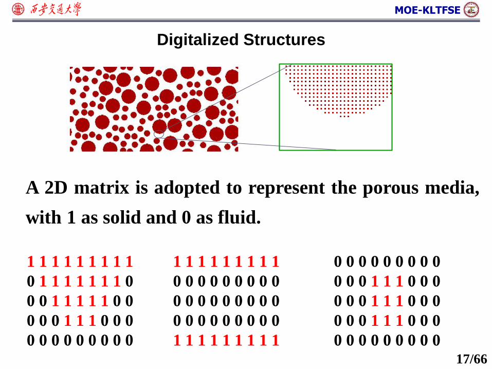
A 2D matrix is adopted to represent the porous media,
with 1 as solid and 0 as fluid.
1 1 1 1 1 1 1 1 1
0 1 1 1 1 1 1 1 0
0 0 1 1 1 1 1 0 0
0 0 0 1 1 1 0 0 0
0 0 0 0 0 0 0 0 0
1 1 1 1 1 1 1 1 1
0 0 0 0 0 0 0 0 0
0 0 0 0 0 0 0 0 0
0 0 0 0 0 0 0 0 0
1 1 1 1 1 1 1 1 1
0 0 0 0 0 0 0 0 0
0 0 0 1 1 1 0 0 0
0 0 0 1 1 1 0 0 0
0 0 0 1 1 1 0 0 0
0 0 0 0 0 0 0 0 0
Digitalized Structures
17/66
MOE-KLTFSE
18/66
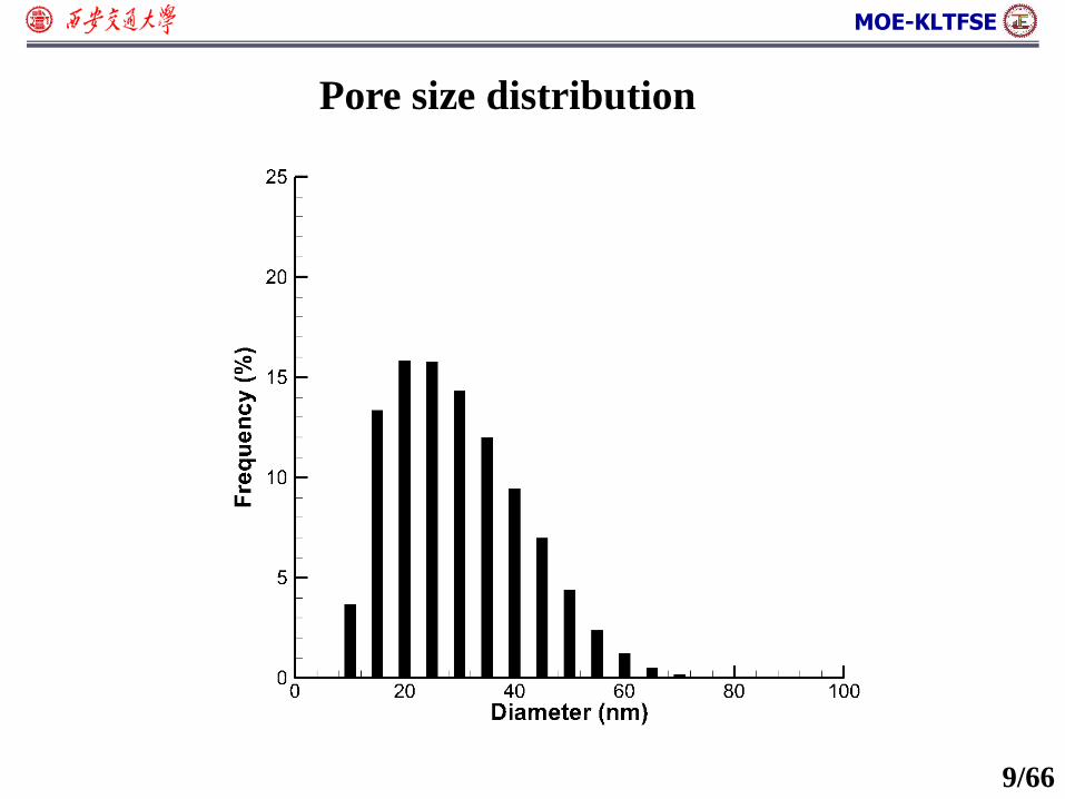
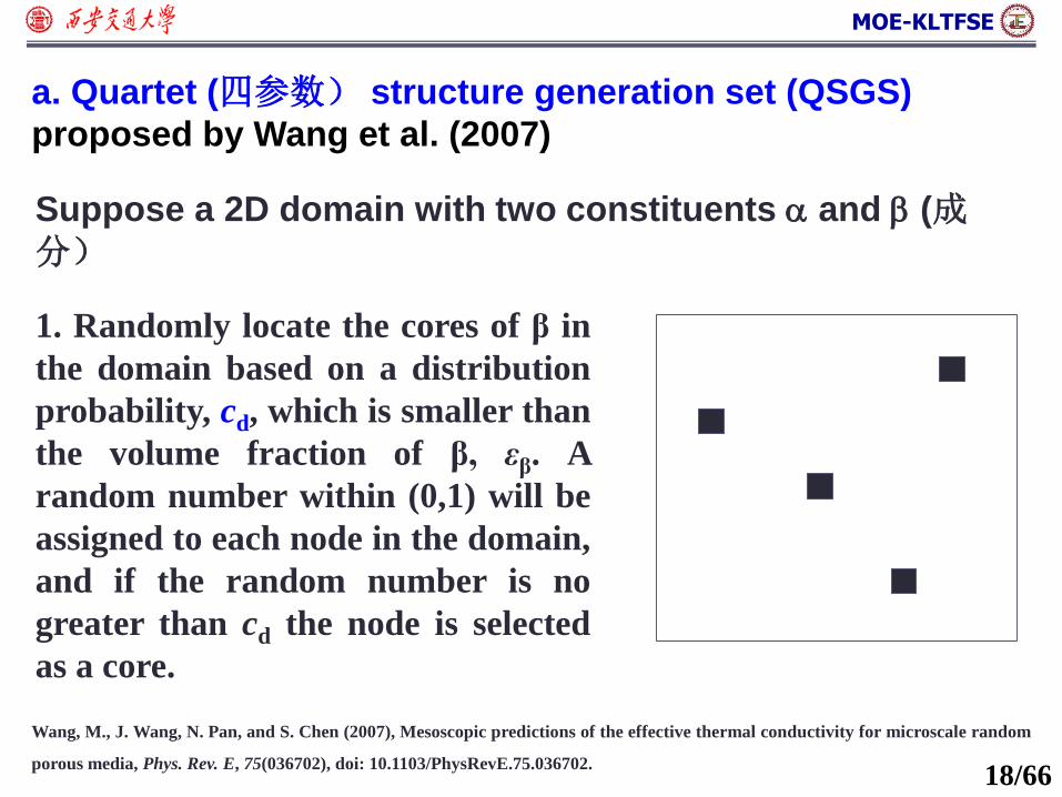
a. Quartet (四参数) structure generation set (QSGS)
proposed by Wang et al. (2007)
Wang, M., J. Wang, N. Pan, and S. Chen (2007), Mesoscopic predictions of the effective thermal conductivity for microscale random
porous media, Phys. Rev. E, 75(036702), doi: 10.1103/PhysRevE.75.036702.
Suppose a 2D domain with two constituents and (成分)
1. Randomly locate the cores of β in
the domain based on a distribution
probability, cd, which is smaller than
the volume fraction of β, εβ. A
random number within (0,1) will be
assigned to each node in the domain,
and if the random number is no
greater than cd the node is selected
as a core.
MOE-KLTFSE
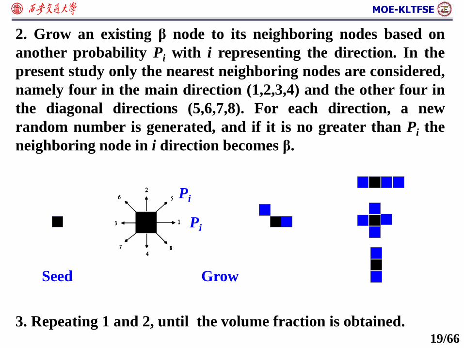
19/66
2. Grow an existing β node to its neighboring nodes based on
another probability Pi with i representing the direction. In the
present study only the nearest neighboring nodes are considered,
namely four in the main direction (1,2,3,4) and the other four in
the diagonal directions (5,6,7,8). For each direction, a new
random number is generated, and if it is no greater than Pi the
neighboring node in i direction becomes β.
Seed Grow
Pi
Pi
3. Repeating 1 and 2, until the volume fraction is obtained.
MOE-KLTFSE
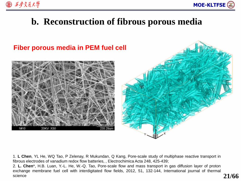
b. Reconstruction of fibrous porous media
1. L Chen, YL He, WQ Tao, P Zelenay, R Mukundan, Q Kang, Pore-scale study of multiphase reactive transport in
fibrous electrodes of vanadium redox flow batteries, , Electrochimica Acta 248, 425-439;
2. L. Chen*, H.B. Luan, Y.-L. He, W.-Q. Tao, Pore-scale flow and mass transport in gas diffusion layer of proton
exchange membrane fuel cell with interdigitated flow fields, 2012, 51, 132-144, International journal of thermal
science
Fiber porous media in PEM fuel cell
21/66
MOE-KLTFSE
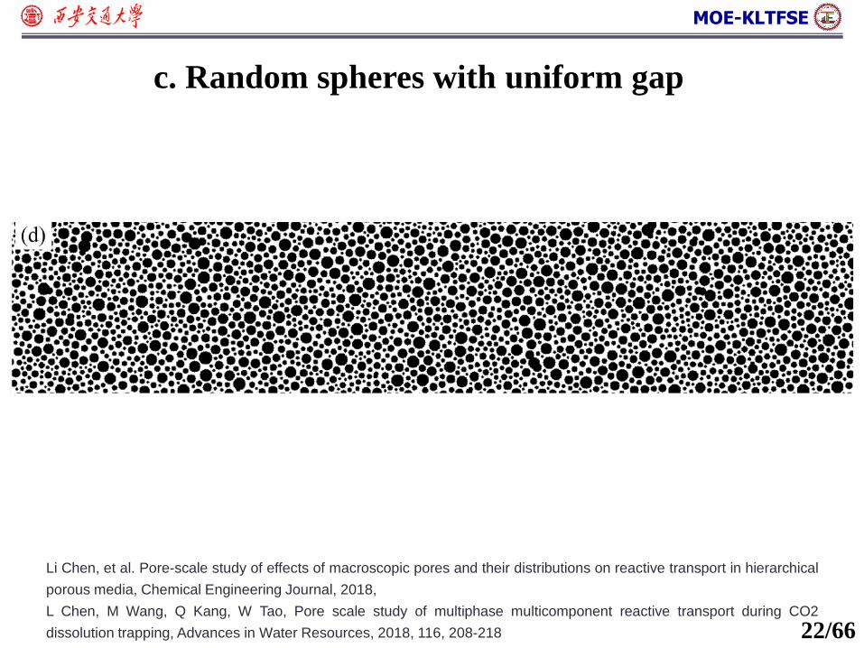
Li Chen, et al. Pore-scale study of effects of macroscopic pores and their distributions on reactive transport in hierarchical
porous media, Chemical Engineering Journal, 2018,
L Chen, M Wang, Q Kang, W Tao, Pore scale study of multiphase multicomponent reactive transport during CO2
dissolution trapping, Advances in Water Resources, 2018, 116, 208-218 22/66
c. Random spheres with uniform gap
MOE-KLTFSE
o 2.1 Examples of porous media
o 2.2 Structural characteristics of porous media
o 2.5 Pore-scale simulation: LB for fluid flow
Content
o 2.4 Pore-scale simulation: reconstruction of porous media
o 2.3 Continuum-scale governing equation for porous media
o 2.6 Pore-scale simulation: LB for heat transfer
23/66
MOE-KLTFSE
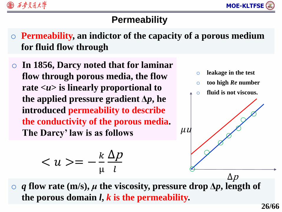
Permeability
o Permeability, an indictor of the capacity of a porous medium
for fluid flow through
o In 1856, Darcy noted that for laminar
flow through porous media, the flow
rate <u> is linearly proportional to
the applied pressure gradient Δp, he
introduced permeability to describe
the conductivity of the porous media.
The Darcy’ law is as follows
o q flow rate (m/s), μ the viscosity, pressure drop Δp, length of
the porous domain l, k is the permeability.
< 𝑢 >= −𝑘
µ
Δp𝑙
Δp
𝜇u
o leakage in the test
o too high Re number
o fluid is not viscous.
26/66
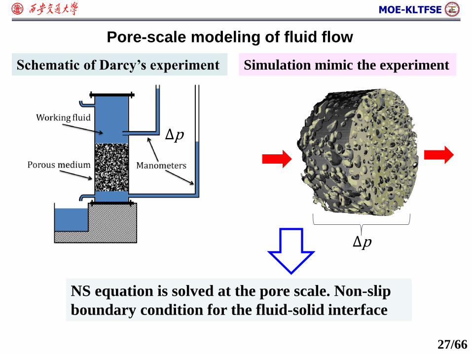
MOE-KLTFSE
Schematic of Darcy’s experiment Simulation mimic the experiment
Δp
Δp
NS equation is solved at the pore scale. Non-slip
boundary condition for the fluid-solid interface
27/66
Pore-scale modeling of fluid flow
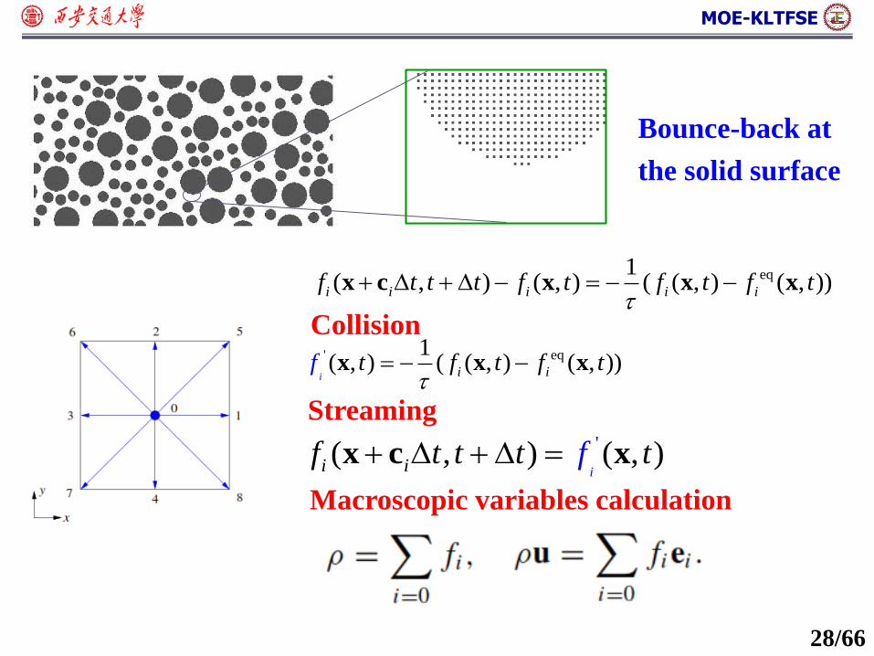
MOE-KLTFSE
eq1( , ) ( , ) ( ( , ) ( , ))i i i i if t t t f t f t f t
x c x x x
Collisioneq' 1
( , ) ( ( , ) ( , ))i i it f t f tf
x x x
'( , ) ( , )ii if t t t f t x c x
Streaming
Macroscopic variables calculation
Bounce-back at
the solid surface
28/66
MOE-KLTFSE
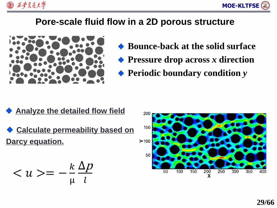
Analyze the detailed flow field
Calculate permeability based on
Darcy equation.
< 𝑢 >= −𝑘
µ
Δp𝑙
Bounce-back at the solid surface
Pressure drop across x direction
Periodic boundary condition y
29/66
Pore-scale fluid flow in a 2D porous structure
MOE-KLTFSE
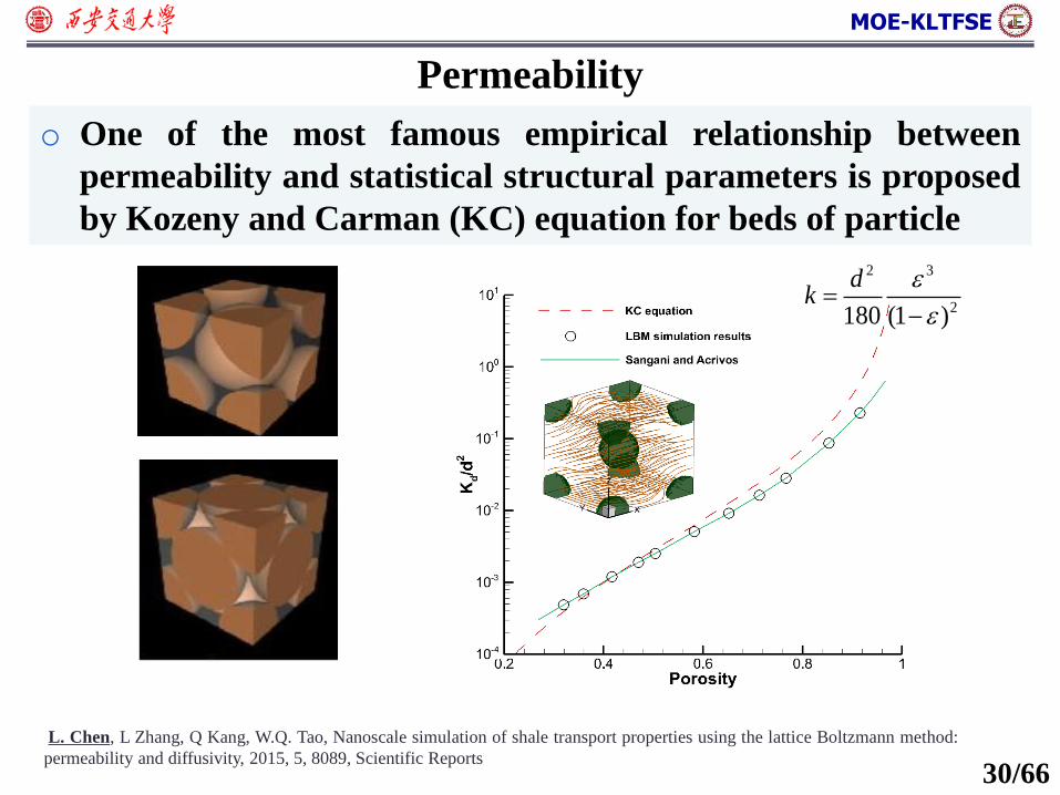
Permeability
o One of the most famous empirical relationship between
permeability and statistical structural parameters is proposed
by Kozeny and Carman (KC) equation for beds of particle
2 3
2180 (1 )
dk
L. Chen, L Zhang, Q Kang, W.Q. Tao, Nanoscale simulation of shale transport properties using the lattice Boltzmann method:
permeability and diffusivity, 2015, 5, 8089, Scientific Reports30/66
MOE-KLTFSE
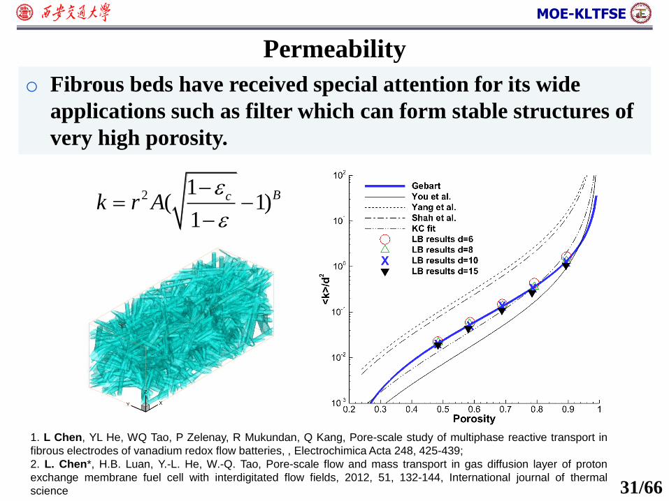
Permeability
o Fibrous beds have received special attention for its wide
applications such as filter which can form stable structures of
very high porosity.
2 1( 1)
1
Bck r A
1. L Chen, YL He, WQ Tao, P Zelenay, R Mukundan, Q Kang, Pore-scale study of multiphase reactive transport in
fibrous electrodes of vanadium redox flow batteries, , Electrochimica Acta 248, 425-439;
2. L. Chen*, H.B. Luan, Y.-L. He, W.-Q. Tao, Pore-scale flow and mass transport in gas diffusion layer of proton
exchange membrane fuel cell with interdigitated flow fields, 2012, 51, 132-144, International journal of thermal
science 31/66

MOE-KLTFSE
o 2.1 Examples of porous media
o 2.2 Structural characteristics of porous media
o 2.5 Pore-scale simulation: LB for fluid flow
Content
o 2.4 Pore-scale simulation: reconstruction of porous media
o 2.3 Continuum-scale governing equation for porous media
o 2.6 Pore-scale simulation: LB for heat transfer
32/66
MOE-KLTFSE
o 2.1 Examples of porous media
o 2.2 Structural characteristics of porous media
o 2.5 Pore-scale simulation: LB for fluid flow
Content
o 2.4 Pore-scale simulation: reconstruction of porous media
o 2.3 Continuum-scale governing equation for porous media
o 2.6 Pore-scale simulation: LB for heat transfer
33/66
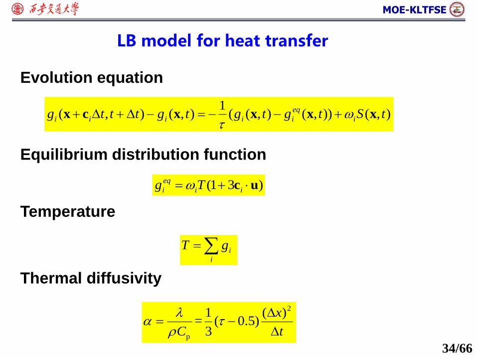
MOE-KLTFSE
LB model for heat transfer
1( , ) ( , ) ( ( , ) ( , )) ( , )eq
i i i i i ig t t t g t g t g t S t x c x x x x
(1 3 )eq
i i ig T c u
i
i
T g
2
p
1 ( )= ( 0.5)
3
x
C t
Evolution equation
Equilibrium distribution function
Temperature
Thermal diffusivity
34/66
MOE-KLTFSE
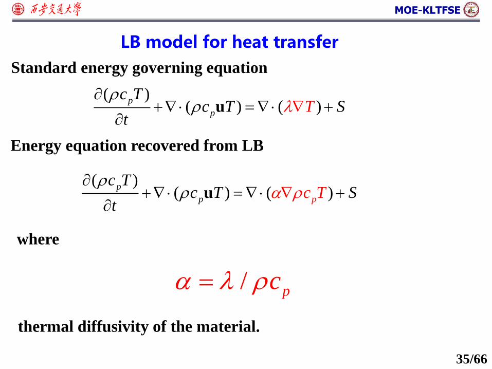
LB model for heat transfer
( )( ) ( )
p
p
c Tc TT S
t
u
Standard energy governing equation
( )( ) ( )p
p
p
TT
tT
cc c S
u
Energy equation recovered from LB
where
/ pc
thermal diffusivity of the material.
35/66
MOE-KLTFSE
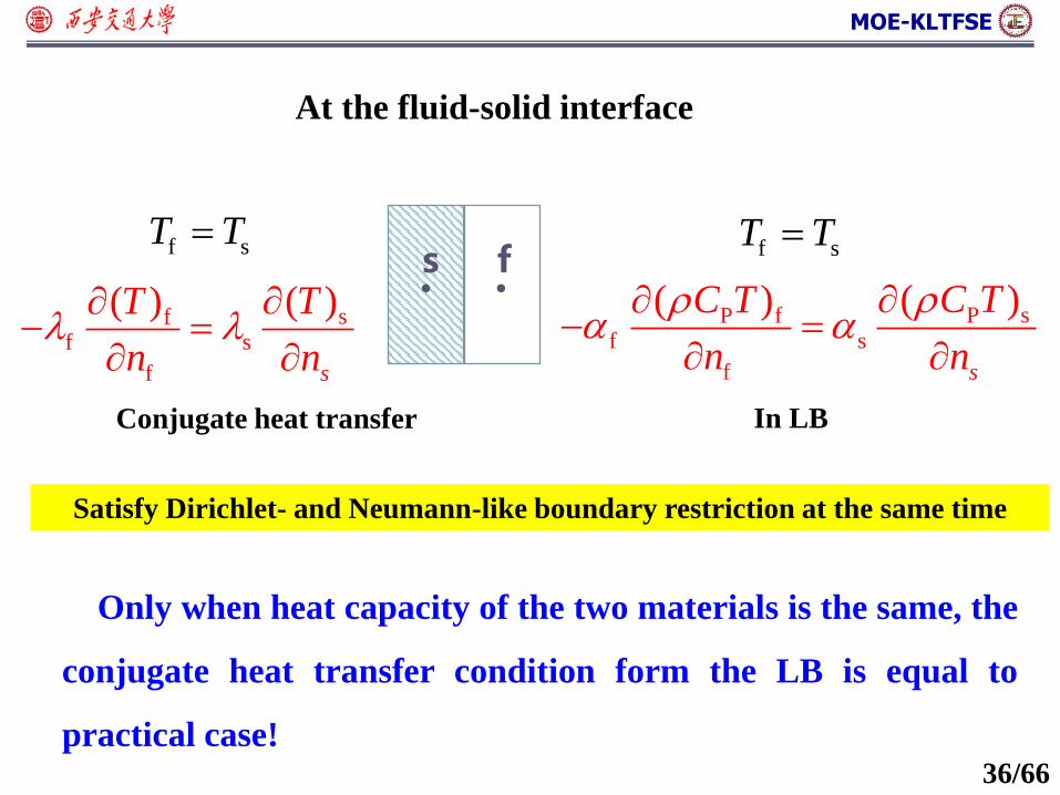
fs
Conjugate heat transfer
At the fluid-solid interface
In LB
f sT T
P sP ff s
f
( )( )
s
C TC T
n n
sf
f s
f
( )( )
s
TT
n n
f sT T
Only when heat capacity of the two materials is the same, the
conjugate heat transfer condition form the LB is equal to
practical case!
Satisfy Dirichlet- and Neumann-like boundary restriction at the same time
36/66
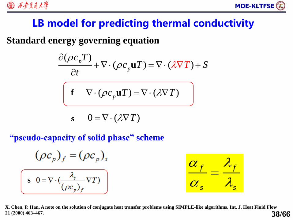
MOE-KLTFSE
( ) ( )upc T T
0 ( )T
f
s
( )( ) ( )
p
p
c Tc TT S
t
u
Standard energy governing equation
LB model for predicting thermal conductivity
“pseudo-capacity of solid phase” scheme
X. Chen, P. Han, A note on the solution of conjugate heat transfer problems using SIMPLE-like algorithms, Int. J. Heat Fluid Flow
21 (2000) 463–467.
s
f f
s s
38/66
MOE-KLTFSE
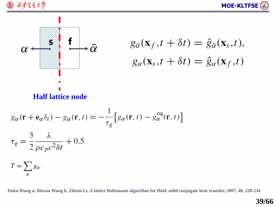
Jinku Wang a, Moran Wang b, Zhixin Li, A lattice Boltzmann algorithm for fluid–solid conjugate heat transfer, 2007, 46, 228-234
fs
Half lattice node
39/66
MOE-KLTFSE
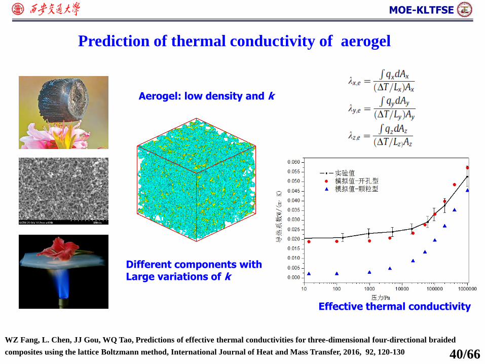
WZ Fang, L. Chen, JJ Gou, WQ Tao, Predictions of effective thermal conductivities for three-dimensional four-directional braided
composites using the lattice Boltzmann method, International Journal of Heat and Mass Transfer, 2016, 92, 120-130
Prediction of thermal conductivity of aerogel
Effective thermal conductivity
Different components with Large variations of k
Aerogel: low density and k
40/66
MOE-KLTFSE
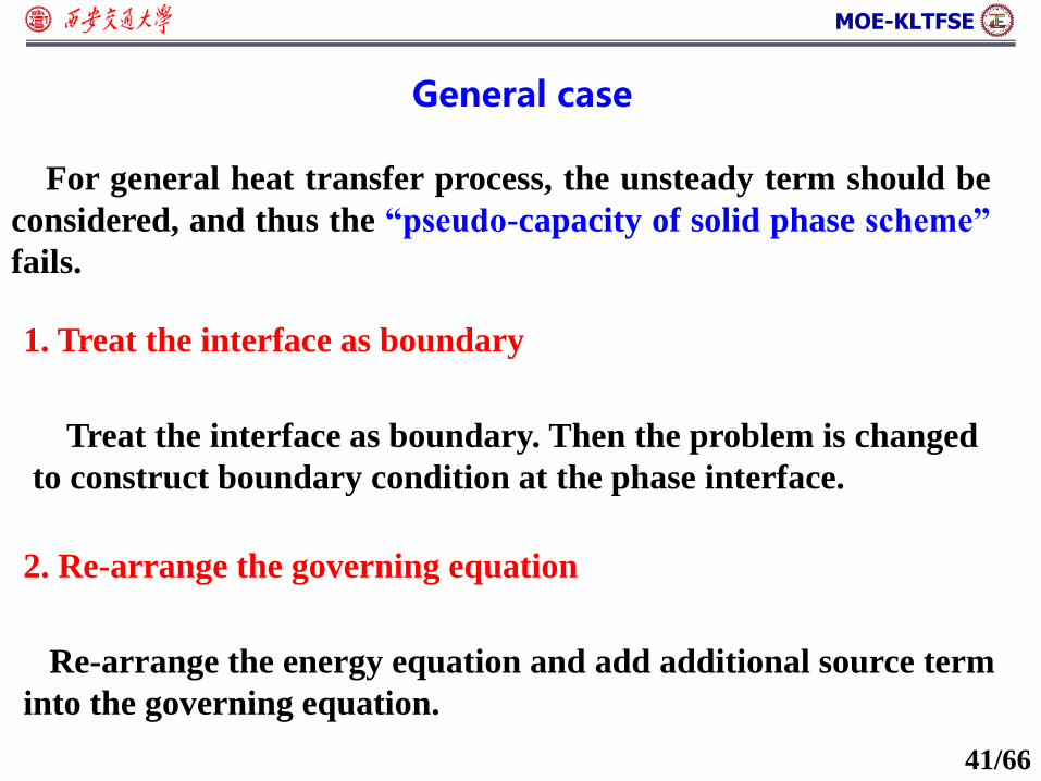
General case
1. Treat the interface as boundary
2. Re-arrange the governing equation
Treat the interface as boundary. Then the problem is changed
to construct boundary condition at the phase interface.
Re-arrange the energy equation and add additional source term
into the governing equation.
For general heat transfer process, the unsteady term should be
considered, and thus the “pseudo-capacity of solid phase scheme”
fails.
41/66
MOE-KLTFSE
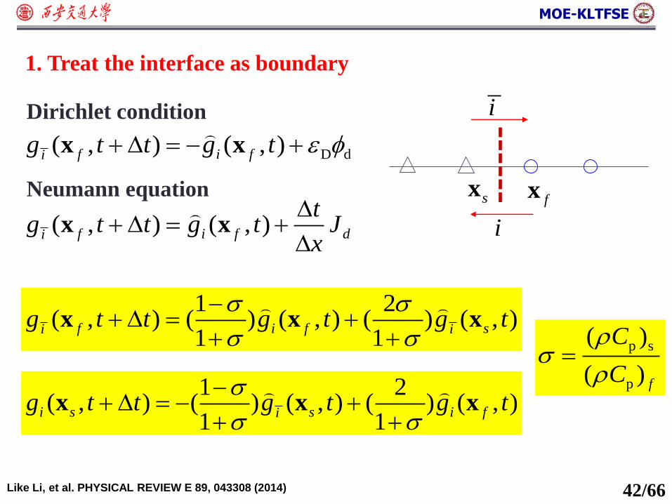
fx
1. Treat the interface as boundary
D d( , ) ( , )f i fig t t g t x x
( , ) ( , )f i f di
tg t t g t J
x
x x
Dirichlet condition
Neumann equation
Like Li, et al. PHYSICAL REVIEW E 89, 043308 (2014)
1 2( , ) ( ) ( , ) ( ) ( , )
1 1f i f si i
g t t g t g t
x x x
1 2( , ) ( ) ( , ) ( ) ( , )
1 1i s s i fi
g t t g t g t
x x x
sx
i
i
p s
p
( )
( ) f
C
C
42/66
MOE-KLTFSE
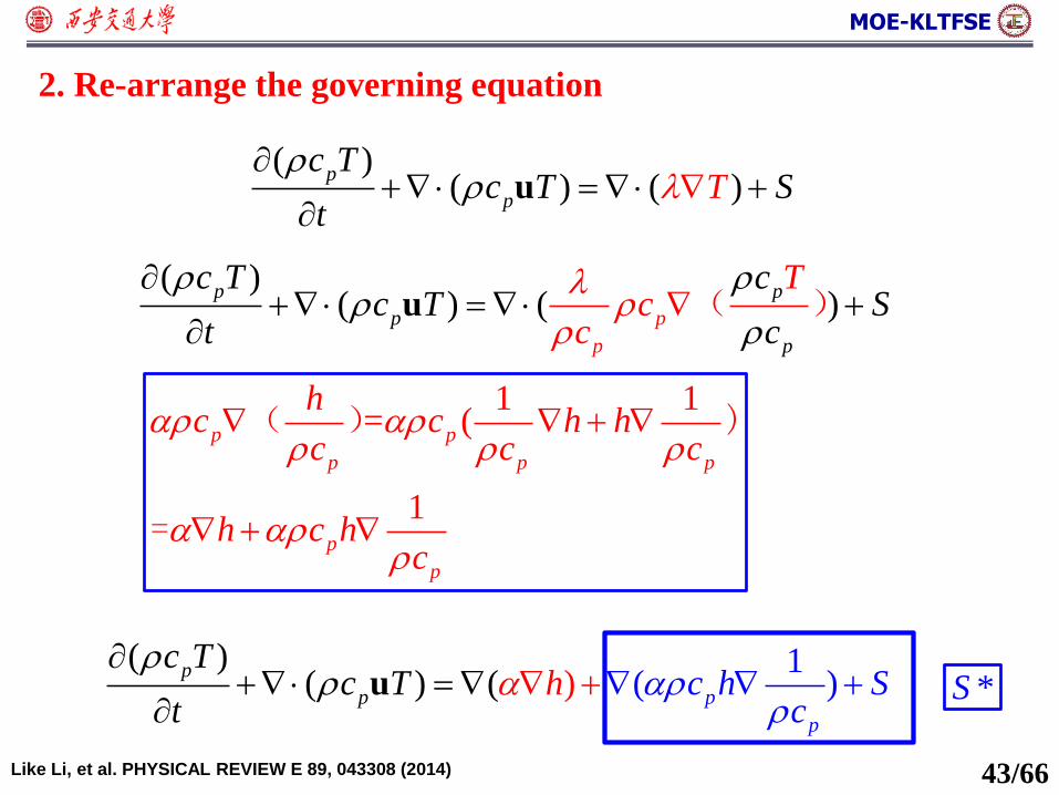
( )( ) ( )
p
p
c Tc TT S
t
u
2. Re-arrange the governing equation
43/66
( )( ) ( )
p
p
p
p
p
p
c T cc T S
t
Tc
c c
u
( )
1 1= (
1
p p
p p p
p
p
hc c h h
c c c
h c hc
( ) )
=
( )( ) (
1)) ( p
p
p
p
c Tc hT c
ctSh
u
*S
Like Li, et al. PHYSICAL REVIEW E 89, 043308 (2014)


![From Lattice Boltzmann Method to Lattice Boltzmann Flux … · From Lattice Boltzmann Method to Lattice Boltzmann Flux Solver Yan Wang 1, ... flows [8,13–15], compressible flows](https://img.pdfslide.net/doc/110x75/5cadf91b88c9938f4d8c0cd6/from-lattice-boltzmann-method-to-lattice-boltzmann-flux-from-lattice-boltzmann.jpg)


![Multiphase lattice Boltzmann simulations for porous media ... · Multiphase lattice Boltzmann simulations for porous media applications 3 the complex pore geometry [17], which restricts](https://img.pdfslide.net/doc/110x75/5e180bacad4ba146a6382852/multiphase-lattice-boltzmann-simulations-for-porous-media-multiphase-lattice.jpg)