Embed Size (px)
Citation preview
Trans. Phenom. Nano Micro Scales, 1(2): 117-123, Summer – Autumn 2013 DOI: 10.7508/tpnms.2013.02.005
ORIGINAL RESEARCH PAPER .
Using Lattice Boltzmann Method to Investigate the Effects of Porous Media on Heat Transfer from Solid Block inside a Channel
Neda Janzadeha, Mojtaba Aghajani Delavarb,* a Islamic Azad University Science and Research Ayatollah Amoli Branch, Amol, Iran b Babol Noshirvani University of Technology, Babol, Iran Abstract
A numerical investigation of forced convection in a channel with hot solid block inside a square porous block mounted on a bottom wall was carried out. The lattice Boltzmann method was applied for numerical simulations. The fluid flow in the porous media was simulated by Brinkman-Forchheimer model. The effects of parameters such as porosity and thermal conductivity ratio over flow pattern and thermal field were investigated. In this paper the effects of mentioned parameters were discussed in detail. The result show with increasing the thermal conductivity ratio and porosity the fluid temperature will reduce.
Keywords: Effective thermal conductivity; Heat transfer; Lattice Boltzmann method; Reynolds number
1. Introduction The heat transfer and transport phenomena in the
porous have been used in many engineering applications such as solid matrix or micro-porous heat exchangers, electronic cooling, chemical catalytic reactors, heat pipe technology, filtering, food processing, fuel cells, air heaters, insulation, porous bearing, solar collectors, nuclear reactors, and many others. Huang and Vafai [1] studied forced convection in a channel with multiple porous blocks arranged on the bottom wall. Kaviany [2] simulated fluid flow and heat transfer in porous media bounded by two isothermal parallel plates. Rizk and Kleinstreuer [3] __________ *Corresponding author Email Address: [email protected]
investigated laminar forced convection in a porous channel with discrete heated blocks and showed an increase in heat transfer can obtain by using porous channel. Zhang et al. [4] numerically simulated the enhancement of combined convective and radioactive heat transfer in a circular duct with a porous core. Hadim [5] investigated forced convection in a channel fully or partially filled with the porous medium He found that the heat transfer is almost, but the pressure drop is about 50% lower. Alkam et al. [6] studied numerically the heat transfer in parallel-plate ducts with porous substrate is attached to the inner wall .They investigated effects of the Darcy number, thermal conductivity and microscopic inertial coefficient on the thermal performance.
117
Delavar et al./ TPNMS 1 (2013) 117-123
118
Nomenclature Greek Symbols
Cp Specific heat( J/kg K) α Thermal diffusivity( m2/s)
Da Darcy number β Thermal expansion coefficient( K-1
) g Gravitational acceleration( m/s
2) µ Dynamic viscosity( kg/m s)
Gr Grashof number ν Kinematic viscosity( m
2/s)
h Heat transfer coefficient( W/m2 K) ϕ Volume fraction of nanoparticles
H Enclosure length( m) ρ Density( kg/m3)
k Thermal conductivity( W/m K) θ Dimensionless temperature
Nu Nusselt number Subscripts
p Pressure( N/m2)
avg Average
P Dimensionless pressure c Cold Pr Prandtl number eff Effective Ra Rayleigh number f Fluid Re Reynolds number h Hot T Temperature( K) nf Nanofluid u,v Velocity components( m/s) s Solid particle
U,V Dimensionless velocity components
x,y Cartesian coordinates( m)
X,Y dimensionless Cartesian coordinates
The lattice Boltzmann method (LBM) is a powerful
numerical technique based on kinetic theory for
simulation of fluid flows and modeling the physics in
fluids [7-9]. Guo and Zhao [10] simulated simulated
successfully the incompressible flows through porous
media by using lattice Boltzmann method. In another
similar approach, the natural convection in porous
media were studied by Seta et al. [11]. In this study
LBM is used to simulate heat transfer and flow pattern
in a channel with solid block located inside a
porous media.
2. Problem Description
The general form of lattice Boltzmann equation
with nine velocities, D2Q9, with external force
can be written as [8]:
( )2
2 4 2
( , ) ( , )
( , ) ( , )
.. 1 1 .. 1
2 2
kk k
eq
k kk
eq kk
kk
s s s
x c t t t x t
tx t f x t tF
c uc u u u
f f
f
fc c c
τ
ρω
+ ∆ + ∆ = +
∆ − + ∆
= + + −
� � �
�
� �
� �� � � �
(1)
where kF�
is the external force, feqk
is the
equilibrium distribution function, t∆ is the lattice
time step, kc�
denotes the discrete lattice velocity
in direction k, τ denotes the lattice relaxation
time, ρ is the lattice fluid density, kω is
weighting factor. To consider both the flow and the
temperature fields, the thermal LBM utilizes two
distribution functions, f and g , for flow and
temperature fields, respectively. The f distribution
function is as same as discussed above; the g
distribution function is as below [8]:
Delavar et al./ TPNMS 1 (2013) 117-123
119
2
( , ) ( , ) ( , ) ( , )
.. . 1
eq
k kk k kg
eqk
kk
s
tx c t t t x t x t g x t
c uT
g g g
gc
τ
ω
∆ + ∆ + ∆ = + −
= +
� � � � �
� �
(2)
The flow properties are defined as (i denote the
component of the Cartesian coordinates):
∑=∑=∑=k
kkik
kik
K gTcfuf ,, ρρ (3)
The Brinkman-Forchheimer equation was used for
flow in porous regions that written as [10,11]
( ) ( ) 21.
1.75
150
eff
u uu p u
t
u u u GK K
εε ρ
ευε
ε
υ∂
+ ∇ = − ∇ + ∂
+ − − +
∇� �
� �
�
� � �
(4)
Where K is the permeability, ε is the porosity,υeff is
the effective viscosity, υ is the kinematic viscosity
and G is the acceleration due to gravity. The last term
in the right hand in the parenthesis is the total body
force, F, which was written by using the widely used
Ergun’s relation [12]. For porous medium the
corresponding distribution functions are as same as
Eq. 1. But the equilibrium distribution functions and
the best choice for the forcing term are [10]:
( )
( )
22
2 4 2
2 4 2
. 1 1. . 1
2 2
.1 .1
.
2
eqk
kk
s s s
k kk
k k
v s s s
c u k
uF : c cc F u F
c u ufc c c
Fc c c
ρε ε
ρε ε
ω
ωτ
= + + −
= − + −
� �
�
� � �� �
� �
� �
�
(5)
The forcing term F k defines the fluid velocity u�
as:
Ft
Fcuk
kk
�
�
2
∆+∑= ρ (6)
According the above equations F�
is related tou�
, so
Eq. (6) is nonlinear for the velocity. A temporal
velocity v�
is used to solve this nonlinear problem
[10]:
2
10
0 13
,20
1 1.751 ,
2 2 2 150
k k
k
v tu v c f G
c c v
t tc c
K K
cρ ε
υε ε
ε
∆= = +
+ +
∆ ∆ = + =
∑�
�
� �
�
(7)
The effective thermal conductivity, effk of the porous
medium should be recognized for proper investigation
of conjugate convection and conduction heat transfer
in porous zone, which was calculated by [13]:
( )
( )
( )2
10 9
2 11 1
1
1 1 1 1ln
2 1
, 1.25 ,
1
1
f
eff f
f
s
kB
B B B
B B
B
kk
B
k
k
εε
σ
σ
σ σ
σ
σ
ε
ε
−= − − +
−
− + − × − − −
= =
−
−
(8)
3. Boundary Condition From the streaming process the distribution functions
out of the domain are known. The unknown
distribution functions are those toward the domain.
Regarding the boundary conditions of the flow field,
the solid walls are assumed to be no slip, and thus the
bounce-back scheme is applied. For example for flow
field in the north boundary the following conditions is
used:
ffffff nnnnnn ,6,8,5,7,2,4, === (9)
In LBM method we need to specify inward
distribution functions at the boundaries. At west
boundary the inlet velocity is known w inlet
u u u= =
.the 1 5,f f and 8f need to be calculated at west
boundary as:
[ ]0 2 4 3 6 7
1, 3,
5, 7, 2, 4,
8, 6, 2, 4,
12( )
1
2
3
1 1( )
2 6
1 1( )
2 6
w
w
n n w
n n n n w w
n n n n w w
f f f f f fu
f f
f f f f u
f f f f u
ρ
ρ
ρ
ρ
= − + + + +−
= +
= − − +
= + − +
(10)
D
The east boundary condition is the outlet condition.
The 3 6,f f and 7f are unknowns distribution functions
for east boundary that calculated by:
3, 3, 1 3, 2
6, 6, 1 6, 2
7, 7, 1 7, 2
2
2
2
n n n
n n n
n n n
f f f
f f f
f f f
− −
− −
− −
= −
= −
= −
For isothermal boundaries such as a bottom hot wall
the unknown distribution functions are evaluated as:
( )
( )
( )
2, 2 4 4,
5, 5 7 7,
6, 6 8 8,
n h n
n h n
n h n
g T g
g T g
g T g
ω ω
ω ω
ω ω
= + −
= + −
= + −
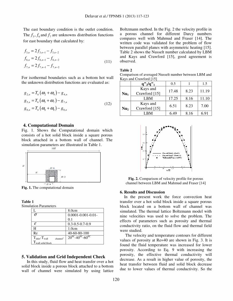
4. Computational Domain Fig. 1. Shows the Computational domain which
consists of a hot solid block inside a square porous
block attached in a bottom wall of channel. The
simulation parameters are illustrated in Table 1.
Fig. 1. The computational domain
Table 1 Simulation Parameters
L 8.0cm σ 0.0001-0.001
0.1
ε 0.3-0.5-0.7-0.9
H 1.0cm Re 40-60-80-100
Tinlet-Twall channel-
Twall solid block 20
0C-40
0C-60
5. Validation and Grid Independent Check In this study, fluid flow and heat transfer over a hot solid block inside a porous block attached to a bottom wall of channel were simulated by using lattice
Delavar et al./ TPNMS 1 (2013) 117-123
120
The east boundary condition is the outlet condition.
distribution functions
(11)
For isothermal boundaries such as a bottom hot wall
the unknown distribution functions are evaluated as:
(12)
Fig. 1. Shows the Computational domain which
inside a square porous
block attached in a bottom wall of channel. The
simulation parameters are illustrated in Table 1.
0.001-0.01-
0.9
100 60
0C
5. Validation and Grid Independent Check In this study, fluid flow and heat transfer over a hot
solid block inside a porous block attached to a bottom wall of channel were simulated by using lattice
Boltzmann method. In the Fig. 2 the velocity profile in a porous channel for different Darcy compares well with Mahmud and Fraser [14]written code was validated for the problem of flow between parallel planes with asymmetric heating [15].Table 2 shows the Nusselt number calculated by LBM and Kays and Crawford [15], good agreement isobserved.
Table 2
Comparison of averaged Nusselt number between LBM and
Kays and Crawford [15]
q"2/q"1 0.5
Nu1
Kays and
Crawford [15] 17.48
LBM 17.25
Nu2
Kays and
Crawford [15] 6.51
LBM 6.49
Fig. 2. Comparison of velocity profile for porous
channel between LBM and Mahmud and Fraser [14]
6. Results and Discussion In the present work the force convection heat
transfer over a hot solid block inside a square porous
block located on a bottom wall of channel was
simulated. The thermal lattice Boltzmann model with
nine velocities was used to solve the problem. The
effects of parameters such as porosity and thermal
conductivity ratio, on the fluid flow and thermal field
were studied.
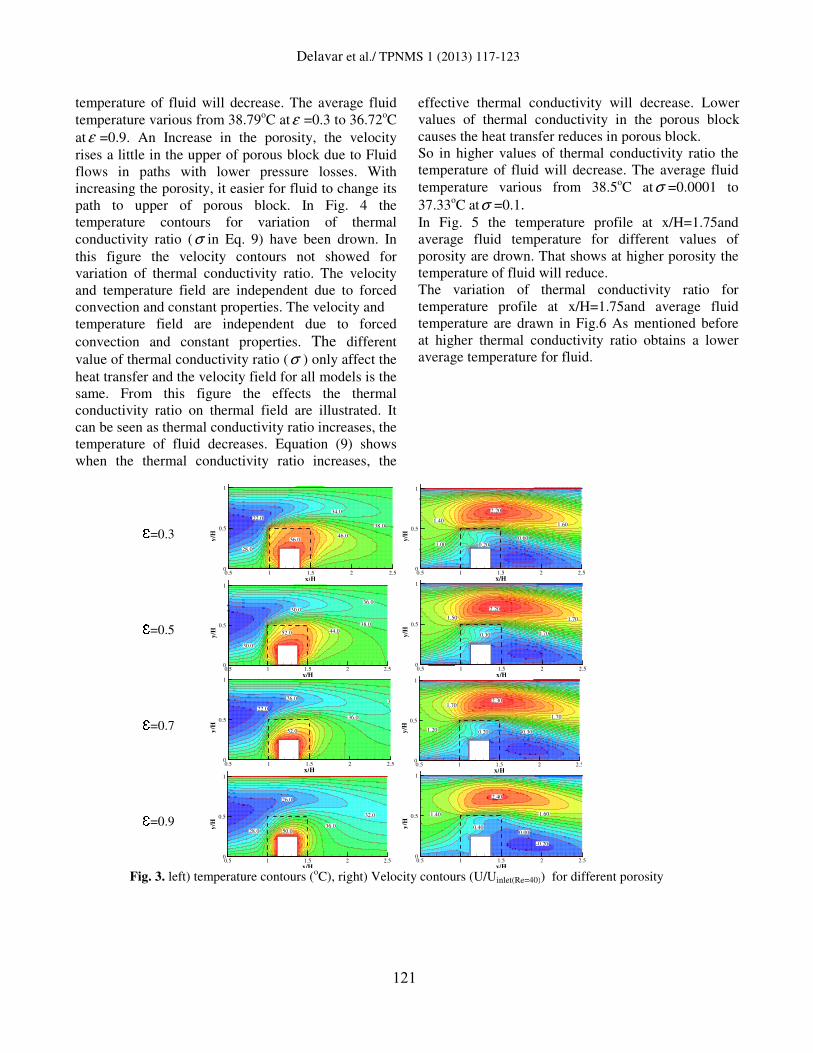
The velocity and temperature contours for different
values of porosity at Re=40 are shown in Fig. 3. It is
found the fluid temperature wa
porosity. According to Eq. 9 with increasing the
porosity, the effective thermal conductivity will
decrease. As a result in higher value of porosity, the
heat transfer between fluid and solid block decrease
due to lower values of thermal conductivity. So the
In the Fig. 2 the velocity profile in a porous channel for different Darcy numbers compares well with Mahmud and Fraser [14]. The written code was validated for the problem of flow between parallel planes with asymmetric heating [15]. Table 2 shows the Nusselt number calculated by LBM and Kays and Crawford [15], good agreement is
Nusselt number between LBM and
0.5 1 1.5
17.48 8.23 11.19
17.25 8.16 11.10
6.51 8.23 7.00
6.49 8.16 6.91
Comparison of velocity profile for porous
channel between LBM and Mahmud and Fraser [14]
In the present work the force convection heat
transfer over a hot solid block inside a square porous
block located on a bottom wall of channel was
rmal lattice Boltzmann model with
nine velocities was used to solve the problem. The
fects of parameters such as porosity and thermal
conductivity ratio, on the fluid flow and thermal field
The velocity and temperature contours for different
values of porosity at Re=40 are shown in Fig. 3. It is
found the fluid temperature was increased for lower
porosity. According to Eq. 9 with increasing the
porosity, the effective thermal conductivity will
decrease. As a result in higher value of porosity, the
heat transfer between fluid and solid block decrease
mal conductivity. So the
Delavar et al./ TPNMS 1 (2013) 117-123
121
temperature of fluid will decrease. The average fluid
temperature various from 38.79oC atε =0.3 to 36.72
oC
atε =0.9. An Increase in the porosity, the velocity
rises a little in the upper of porous block due to Fluid
flows in paths with lower pressure losses. With
increasing the porosity, it easier for fluid to change its
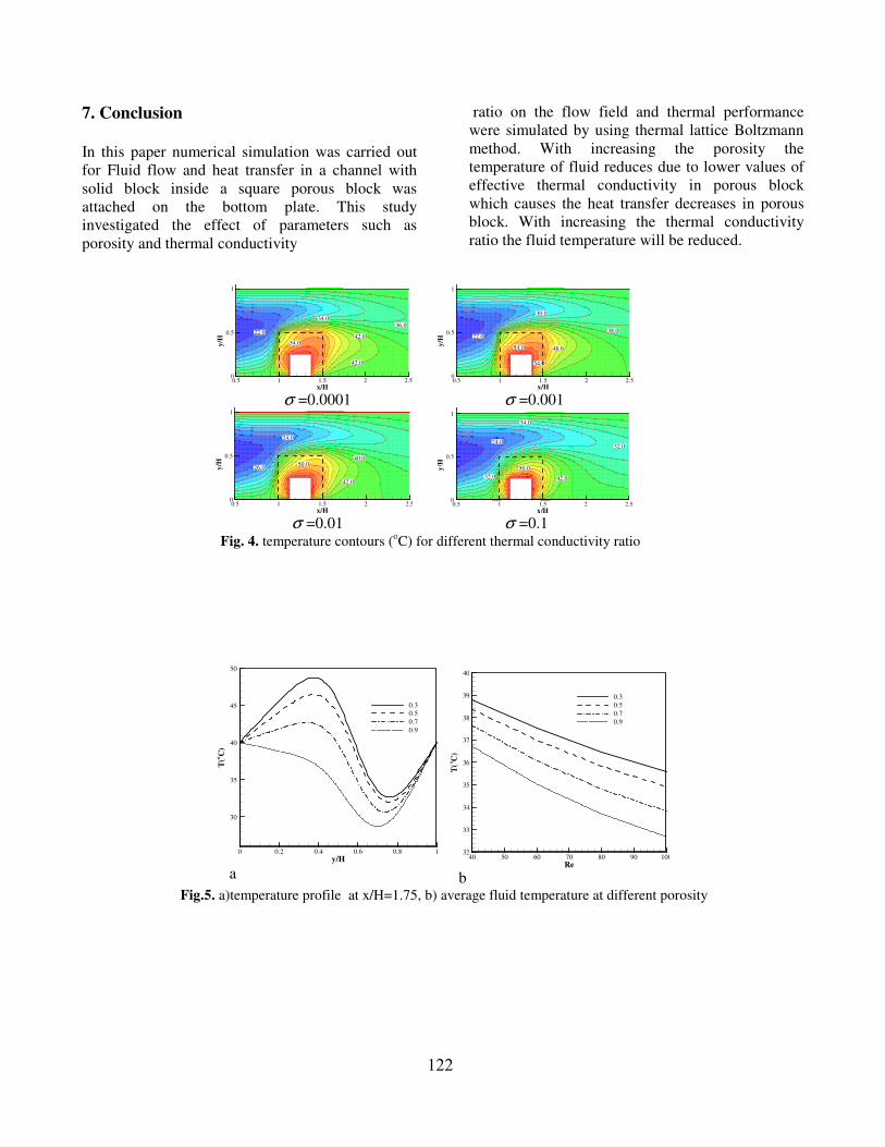
path to upper of porous block. In Fig. 4 the
temperature contours for variation of thermal
conductivity ratio (σ in Eq. 9) have been drown. In
this figure the velocity contours not showed for
variation of thermal conductivity ratio. The velocity
and temperature field are independent due to forced
convection and constant properties. The velocity and
temperature field are independent due to forced
convection and constant properties. The different
value of thermal conductivity ratio (σ ) only affect the
heat transfer and the velocity field for all models is the
same. From this figure the effects the thermal
conductivity ratio on thermal field are illustrated. It
can be seen as thermal conductivity ratio increases, the
temperature of fluid decreases. Equation (9) shows
when the thermal conductivity ratio increases, the
effective thermal conductivity will decrease. Lower
values of thermal conductivity in the porous block
causes the heat transfer reduces in porous block.
So in higher values of thermal conductivity ratio the
temperature of fluid will decrease. The average fluid
temperature various from 38.5oC atσ =0.0001 to
37.33oC atσ =0.1.
In Fig. 5 the temperature profile at x/H=1.75and
average fluid temperature for different values of
porosity are drown. That shows at higher porosity the
temperature of fluid will reduce.
The variation of thermal conductivity ratio for
temperature profile at x/H=1.75and average fluid
temperature are drawn in Fig.6 As mentioned before
at higher thermal conductivity ratio obtains a lower
average temperature for fluid.
Ɛ=0.3
Ɛ=0.5
Ɛ=0.7
Ɛ=0.9
Fig. 3. left) temperature contours (oC), right) Velocity contours (U/Uinlet(Re=40)) for different porosity
56.046.0
38.0
34.0
22.0
28.0
x/H
y/H
0.5 1 1.5 2 2.50
0.5
1
2.20
0.60
0.201.00
1.601.40
x/H
y/H
0.5 1 1.5 2 2.50
0.5
1
30.0
52.0 44.0
38.0
30.0
36.0
x/H
y/H
0.5 1 1.5 2 2.50
0.5
1
2.20
0.70
1.70
0.30
1.50
x/H
y/H
0.5 1 1.5 2 2.50
0.5
1
26.0
52.0
36.0
34
22.0
x/H
y/H
0.5 1 1.5 2 2.50
0.5
1
2.30
0.300.201.20
1.70
1.70
x/H
y/H
0.5 1 1.5 2 2.50
0.5
1
26.0
50.036.0
32.0
28.0
x/H
y/H
0.5 1 1.5 2 2.50
0.5
1
2.40
1.60
0.000.40
-0.20
1.40
x/H
y/H
0.5 1 1.5 2 2.50
0.5
1
122
7. Conclusion
In this paper numerical simulation was carried out
for Fluid flow and heat transfer in a channel with
solid block inside a square porous block was
attached on the bottom plate. This study
investigated the effect of parameters such as
porosity and thermal conductivity
ratio on the flow field and thermal performance
were simulated by using thermal lattice Boltzmann
method. With increasing the porosity the
temperature of fluid reduces due to lower values of
effective thermal conductivity in porous block
which causes the heat transfer decreases in porous
block. With increasing the thermal conductivity
ratio the fluid temperature will be reduced.
σ =0.0001 σ =0.001
σ =0.01 σ =0.1
Fig. 4. temperature contours (oC) for different thermal conductivity ratio
a b Fig.5. a)temperature profile at x/H=1.75, b) average fluid temperature at different porosity
22.0
54.0
34.0
42.0
36.0
42.0
x/H
y/H
0.5 1 1.5 2 2.50
0.5
1
54.0
54.0
48.0
30.0
22.038.0
x/H
y/H
0.5 1 1.5 2 2.50
0.5
1
24.0
50.040.0
42.0
26.0
x/H
y/H
0.5 1 1.5 2 2.50
0.5
1
34.0
50.0
42.0
32.024.0
32.0
x/H
y/H
0.5 1 1.5 2 2.50
0.5
1
Re
T(o
C)
40 50 60 70 80 90 10032
33
34
35
36
37
38
39
40
0.3
0.5
0.7
0.9
y/H
T(o
C)
0 0.2 0.4 0.6 0.8 1
30
35
40
45
50
0.3
0.5
0.7
0.9
Delavar et al./ TPNMS 1 (2013) 117-123
123
a b
Fig.6. a)temperature profile at x/H=1.75, b) average fluid temperature at different thermal conductivity ratio
References
[1] P.C. Huang, K. Vafai, Analysis of forced convection
enhancement in a channel using porous blocks, AIAA J.
Thermophys. Heat Transfer 18 (1994) 563–573.
[2] M. Kaviany, Laminar flow through a porous channel
bounded by isothermal parallel plate, Int. J. Heat
MassTransfer 28 (1985) 851–858.
[3] T. Rizk, C. Kleinstreuer, Forced convective cooling
of a linear array of blocks in open and porous matrix
channels, Heat. Transfer Eng 12 (1991) 4–47.
[4] J.M. Zhang, W.H. Sutton , F.C. Lai, Enhancement of
heat transfer using porous convection-to-radiation
converter for laminar flow in a circular duct, Int. J. Heat
Mass Transfer 40 (1996) 39–48.
[5] A. Hadim, Forced convection in a porous channel
with localized heat sources, ASME J. Heat Transfer 8
(1994) 465–472.
[6] M.K. Alkam, M.A. Al-Nimr, M.O. Hamdan,
Enhancing heat transfer in parallel plate channels by
using porous inserts, Int. J. Heat Mass Transfer 44 (2001)
931–938.
[7] S. Succi, The Lattice Boltzmann Equation for Fluid
Dynamics and Beyond, Clarendon
Press, Oxford, 2001.
[8] A. A. Mohammad, Lattice Boltzmann Method,
Fundamentals and Engineering Applications with
Computer Codes, Springer, London, England, 2011.
[9] P. H. Kao, Y. H. Chen, R. J. Yang: Simulations of the
macroscopic and mesoscopic natural convection flows
within rectangular cavities, International Journal of Heat
and Mass Transfer, 51(2008) 3776–3793.
[10] Z. Guo, T.S. Zhao, Lattice Boltzmann model for
incompressible flows through porous media, Phys. Rev.
E 66 (2002) 036304.
[11] T. Seta, E. Takegoshi, K. Okui, Lattice Boltzmann
simulation of natural convection in porous media, Math.
Comput. Simul. 72 (2006) 195–200.
[12] S. Ergun, Chem. Eng. Prog, 48(1952) 89.
[13] P.X. Jiang, X.C Lu, Int. J. Heat and Mass Transfer,
49 (2006) 1685
[14] S. Mahmud and R. A. Fraser, Flow, thermal, and
entropy generation characteristics inside a porous
channel with viscous dissipation, International Journal of
Thermal Sciences, 44 (2005) 21-32.
[15] W. M. Kays, M. E. Crawford, Solutions Manual,
Convective Heat and Mass Transfer, third ed., McGraw-
Hill, New York, 1993.
Re
T(o
C)
40 50 60 70 80 90 10033
34
35
36
37
38
39
0.0001
0.001
0.01
0.1
y/H
T(o
C)
0 0.2 0.4 0.6 0.8 126
28
30
32
34
36
38
40
42
44
46
48
50
0.0001
0.001
0.01
0.1


![Improving computational efficiency of lattice Boltzmann ... · 1.1 The lattice Boltzmann method The lattice Boltzmann method [7] [20] is a relative new technique to CFD. Classical](https://img.pdfslide.net/doc/110x75/5f03952b7e708231d409c3df/improving-computational-efficiency-of-lattice-boltzmann-11-the-lattice-boltzmann.jpg)