Embed Size (px)
Citation preview
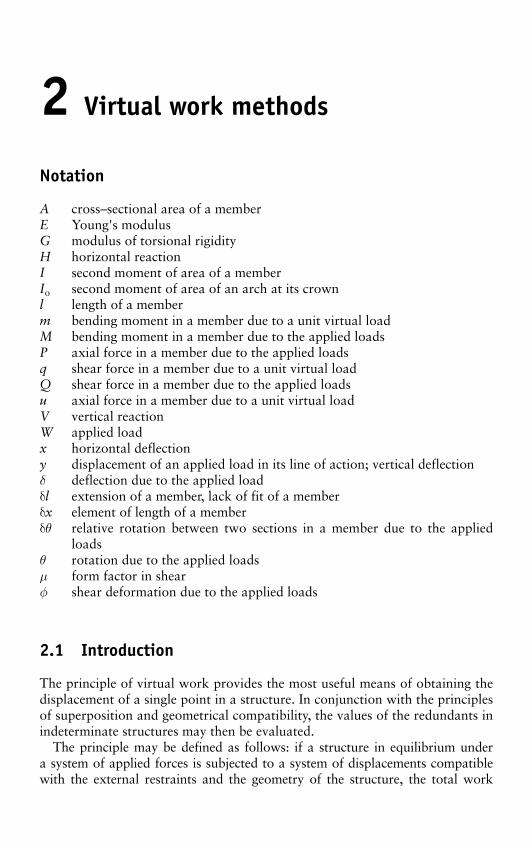
2 Virtual work methods
Notation
A cross – sectional area of a member E Young's modulus G modulus of torsional rigidity H horizontal reaction I second moment of area of a member I o second moment of area of an arch at its crown l length of a member m bending moment in a member due to a unit virtual load M bending moment in a member due to the applied loads P axial force in a member due to the applied loads q shear force in a member due to a unit virtual load Q shear force in a member due to the applied loads u axial force in a member due to a unit virtual load V vertical reaction W applied load x horizontal deflection y displacement of an applied load in its line of action; vertical deflection δ deflection due to the applied load δ l extension of a member, lack of fit of a member δ x element of length of a member δ θ relative rotation between two sections in a member due to the applied
loads θ rotation due to the applied loads μ form factor in shear φ shear deformation due to the applied loads
2.1 Introduction
The principle of virtual work provides the most useful means of obtaining the displacement of a single point in a structure. In conjunction with the principles of superposition and geometrical compatibility, the values of the redundants in indeterminate structures may then be evaluated.
The principle may be defined as follows: if a structure in equilibrium under a system of applied forces is subjected to a system of displacements compatible with the external restraints and the geometry of the structure, the total work
Structural Analysis: In Theory and Practice160
done by the applied forces during these external displacements equals the work done by the internal forces, corresponding to the applied forces, during the inter-nal deformations, corresponding to the external displacements. The expression “virtual work ” signifies that the work done is the product of a real loading sys-tem and imaginary displacements or an imaginary loading system and real dis-placements. Thus, in Chapters 2 and 3 and Sections 6.2, 6.4, 6.5, 9.8, and 10.3 displacements are obtained by considering virtual forces undergoing real dis-placements, while in Sections 7.8 –7.14, 9.5 –9.8, and 11.3 equilibrium relation-ships are obtained by considering real forces undergoing virtual displacements.
A rigorous proof of the principle based on equations of equilibrium has been given by Di Maggio 1 . A derivation of the virtual-work expressions for linear structures is given in the following section.
2.2 Virtual-work relationships
�
Pl /AE
MM
R
P
Q
1
1 1
1 1
Q
PW
23
y
4�l
�θ ��x/R�M�x/EI
l
�
f
f�x
�x �x(i)
(ii) (iii)
3 2 3 2
4 4
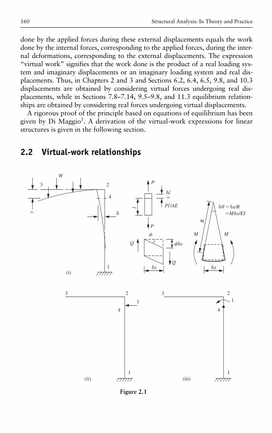
Figure 2.1
Virtual work methods 161
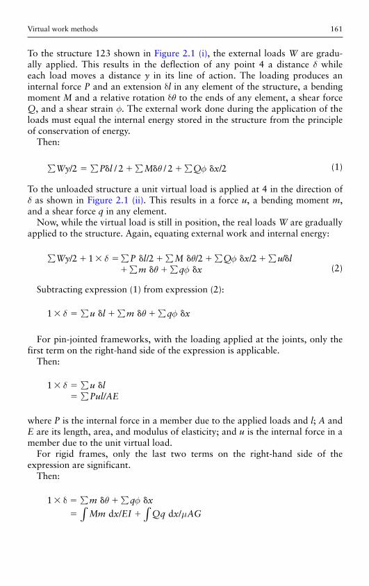
To the structure 123 shown in Figure 2.1 (i), the external loads W are gradu-ally applied. This results in the deflection of any point 4 a distance δ while each load moves a distance y in its line of action. The loading produces an internal force P and an extension δ l in any element of the structure, a bending moment M and a relative rotation δθ to the ends of any element, a shear force Q, and a shear strain φ. The external work done during the application of the loads must equal the internal energy stored in the structure from the principle of conservation of energy.
Then:
∑ ∑ ∑ ∑Wy P l M Q x/ / / /2 2 2� � � � � �2 θ φ (1)
To the unloaded structure a unit virtual load is applied at 4 in the direction of δ as shown in Figure 2.1 (ii). This results in a force u, a bending moment m , and a shear force q in any element.
Now, while the virtual load is still in position, the real loads W are gradually applied to the structure. Again, equating external work and internal energy:
δ θ φ
θ φ∑ ∑ ∑ ∑ ∑
∑ ∑� � � � � � � � � �
� � � �/2 1 /2 /2 /2 /Wy P l M Q x u l
m q x (2)
Subtracting expression (1) from expression (2):
1 � � � � � � �δ θ∑ ∑ ∑u l m q x φ
For pin-jointed frameworks, with the loading applied at the joints, only the first term on the right-hand side of the expression is applicable.
Then:
1 � � ��
δ ∑∑
u lPul/AE
where P is the internal force in a member due to the applied loads and l; A and E are its length, area, and modulus of elasticity; and u is the internal force in a member due to the unit virtual load.
For rigid frames, only the last two terms on the right-hand side of the expression are significant.
Then:
1 � � � � �
� �
δ ∑ ∑
∫ ∫m q x
Mm x EI Qq x AG d / d /θ φ
μ
Structural Analysis: In Theory and Practice162
where M and Q are the bending moment and shear force at any section due to the applied loads and I, G and A are the second moment of area, the rigidity modulus, and the area of the section; μ is the form factor; and m and q are the bending moment and shear force at any section due to the unit virtual load.
Usually the term representing the deflection due to shear can be neglected, and the expression reduces to:
1 � �δ Mm x EI d /∫
In a similar manner, the rotation θ of any point 4 of the structure may be obtained by applying a unit virtual bending moment at 4 in the direction of θ .
Then:
1 � � �θ μMm x EI Qq x AG d / d /∫ ∫�
where m and q are the bending moment and shear force at any section due to the unit virtual moment.
2.3 Sign convention
For a pin-jointed frame, tensile forces are considered positive and compressive forces negative. Increase in the length of a member is considered positive and decrease in length negative. The unit virtual load is applied to the frame in the anticipated direction of the deflection. If the assumed direction is correct, the deflection obtained will have a positive value. The deflection obtained will be negative when the unit virtual load has been applied in the opposite direction to the actual deflection.
For a rigid frame, moments produced by the virtual load or moment are considered positive, and moments produced by the applied loads, which are of opposite sense, are considered negative. A positive value for the displacement indicates that the displacement is in the same direction as the virtual force or moment.
2.4 Illustrative examples
Example 2.1
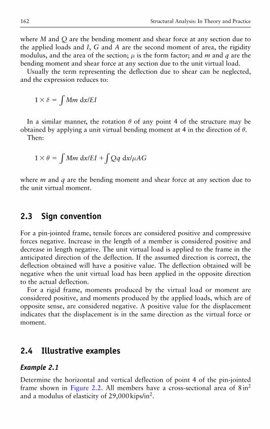
Determine the horizontal and vertical deflection of point 4 of the pin-jointed frame shown in Figure 2.2 . All members have a cross-sectional area of 8 in 2 and a modulus of elasticity of 29,000 kips/in 2 .
Virtual work methods 163
Solution
Member forces u 1 due to a vertical unit load at 4 are obtained from (i) and are tabulated in Table 2.1 . The stresses in each member, P/A, due to the real load of 16 kips are given by:
P A uu
/ /� ��
16 182
1
1
Member forces u 2 due to a horizontal unit load at 4 are obtained from (ii) and are tabulated in Table 2.1 .
3 4
16k 1k
1k
12�
12�
5
6
9�9�
2
1
(i) (ii)
Figure 2.2
Table 2.1 Determination of forces and displacements in Example 2.1
Member P / A l u1 u 2 Pu 1 l / A Pu 2 l / A
12 2.0 12 1.00 �2.67 24.00 � 64.0 23 2.5 15 1.25 �1.67 46.88 � 62.5 34 1.5 9 0.75 �1.00 10.12 � 13.5 45 �2.5 15 �1.25 0 46.88 0 56 �4.0 12 �2.00 1.33 96.00 � 64.0 53 �2.0 12 �1.00 1.33 24.00 � 32.0 52 �1.5 9 �0.75 0 10.12 0 26 0 15 0 1.67 0 0
Total 258.0 � 236.0
The vertical deflection is given by:
v Pu l AE�� ��
∑ 1258 12 29 0000 107
// ,
. in downward
Structural Analysis: In Theory and Practice164
The horizontal deflection is given by:
h Pu l AE�� � ��
∑ 2236 12 29 000
0 098
// ,
. in to the right
Example 2.2
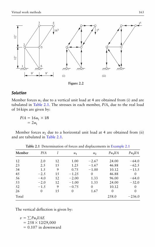
Determine the deflection at the free end of the cantilever shown in Figure 2.3 . The cross-section is shown at (i), the modulus of elasticity is 29,000 kips/in 2 , the modulus of rigidity is 11,200 kips/in 2, and the shear stress may be assumed to be uniformly distributed over the web area.
8�
0.4�
6�
0.7�
14�
1 122x
M
Q3k
33
3k 3k
1k
4�
1
2x
m
q
12k-
ft
24k-
ft
3
1k
(i) (ii) (iii)
Figure 2.3
Solution
The origin of coordinates is taken at 2 and the functions M and Q derived from (ii) as:
M x� 3 and Q � 3
A unit vertical load is applied at 3 and the functions m and q derived from (iii) as:
m x� �4 and q � 1.
The moment of inertia and the area of the web are given by:
I
A
� � � �
�
� �
�
6 14 12 5 6 12 6 12440
0 4 14 1 4
5 04
3 3( ) . ( . ) /
. ( . )
.
/in
in
4
2
Virtual work methods 165
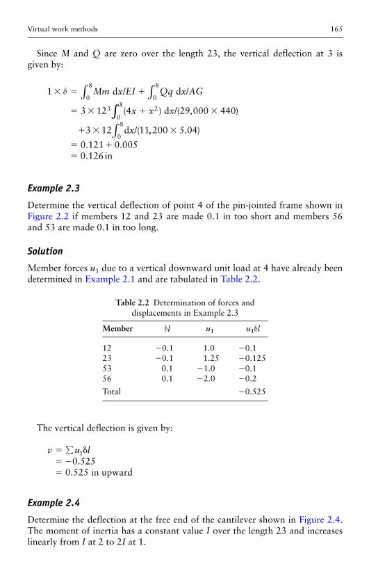
Since M and Q are zero over the length 23, the vertical deflection at 3 is given by:
1
3 12 4 29 000 440
0
8
0
8
3 20
8
� � �
� � � �
δ Mm x EI Qq x AG
x x x
d / d
d
∫ ∫ /
( ) /( , )∫∫∫� � �
� ��
3 12 11 200 5 04
0 121 0 0050 126
0
8d
in
x/( , . )
. .
.
Example 2.3
Determine the vertical deflection of point 4 of the pin-jointed frame shown in Figure 2.2 if members 12 and 23 are made 0.1 in too short and members 56 and 53 are made 0.1 in too long.
Solution
Member forces u 1 due to a vertical downward unit load at 4 have already been determined in Example 2.1 and are tabulated in Table 2.2 .
Table 2.2 Determination of forces and displacements in Example 2.3
Member δ l u 1 u 1 δ l
12 �0.1 1.0 � 0.1 23 �0.1 1.25 � 0.125 53 0.1 �1.0 � 0.1 56 0.1 �2.0 � 0.2
Total � 0.525
The vertical deflection is given by:
v u l� �� ��
∑ 10 525
0 525.
. in upward
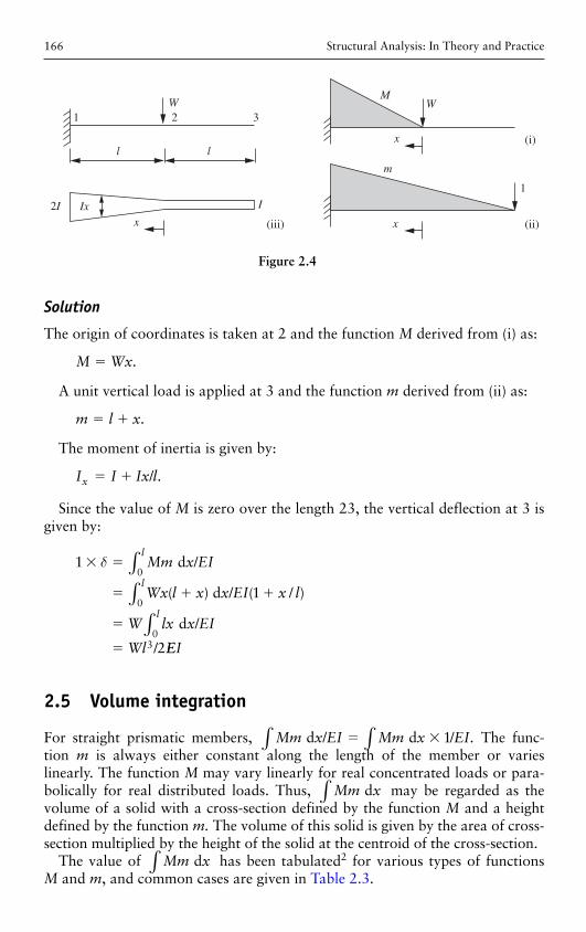
Example 2.4
Determine the deflection at the free end of the cantilever shown in Figure 2.4 . The moment of inertia has a constant value I over the length 23 and increases linearly from I at 2 to 2 I at 1.
Structural Analysis: In Theory and Practice166
Solution
The origin of coordinates is taken at 2 and the function M derived from (i) as:
M Wx� .
A unit vertical load is applied at 3 and the function m derived from (ii) as:
m l x� � .
The moment of inertia is given by:
I I Ix lx � � / .
Since the value of M is zero over the length 23, the vertical deflection at 3 is given by:
1
1
2
0
0
03
� �
� � �
�
�
δ Mm x EI
Wx l x x EI x l
W lx x EI
Wl
l
l
l
∫∫
∫
d
d
d
/
( ) / ( / )
/
/ EEI
2.5 Volume integration
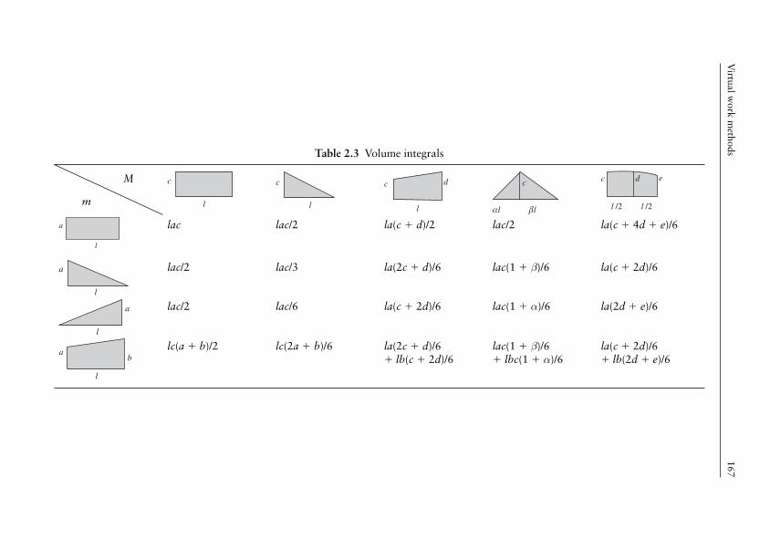
For straight prismatic members, Mm x EI Mm x EI d d ./ /� � 1∫∫ The func-tion m is always either constant along the length of the member or varies linearly. The function M may vary linearly for real concentrated loads or para-bolically for real distributed loads. Thus, Mm x d∫ may be regarded as the volume of a solid with a cross-section defined by the function M and a height defined by the function m. The volume of this solid is given by the area of cross-section multiplied by the height of the solid at the centroid of the cross-section.
The value of Mm x d∫ has been tabulated 2 for various types of functions M and m , and common cases are given in Table 2.3 .
1
Ixx
2W
3
l
I
1
2I
l
M
m
x
W
x (i)
(ii)(iii)
Figure 2.4
Virtual w
ork methods
167
Table 2.3 Volume integrals
M
m l
c
l
c
l
c d
αl βl
c
l /2 l /2
c d e
a
l
lac lac/2 la ( c � d)/2 lac/2 la ( c � 4 d � e )/6
a
l
lac/2 lac/3 la (2 c � d)/6 lac (1 � β)/6 la ( c � 2 d )/6
a
l
lac/2 lac/6 la ( c � 2 d)/6 lac (1 � α)/6 la (2 d � e )/6
ab
l
lc ( a � b)/2 lc(2a � b)/6 la (2 c � d )/6 � lb ( c � 2 d )/6
lac (1 � β )/6 � lbc (1 � α )/6
la ( c � 2 d )/6 � lb (2 d � e )/6
Structural Analysis: In Theory and Practice168
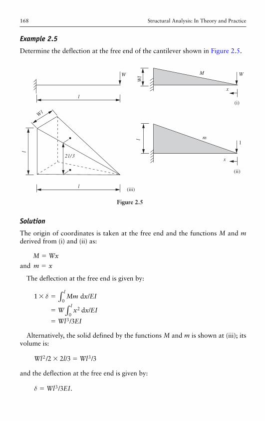
Example 2.5
Determine the deflection at the free end of the cantilever shown in Figure 2.5 .
W
1
M
Wl
l
W
Wl
l m
x
x
(i)
(ii)
(iii)
l
l
2 l /3
Figure 2.5
Solution
The origin of coordinates is taken at the free end and the functions M and m derived from (i) and (ii) as:
M Wx� and m x�
The deflection at the free end is given by:
1
3
0
20
3
� �
�
�
δ Mm x EI
W x x EI
Wl EI
l
l
d /
d
∫∫ /
/
Alternatively, the solid defined by the functions M and m is shown at (iii); its volume is:
Wl l Wl2 32 2 3 3/ / /� �
and the deflection at the free end is given by:
δ � Wl EI3 3/ .
Virtual work methods 169
Alternatively, from Table 2.3 , the value of Mm x EI d /∫ is given by:
δ �
�
lac EIWl
//
333
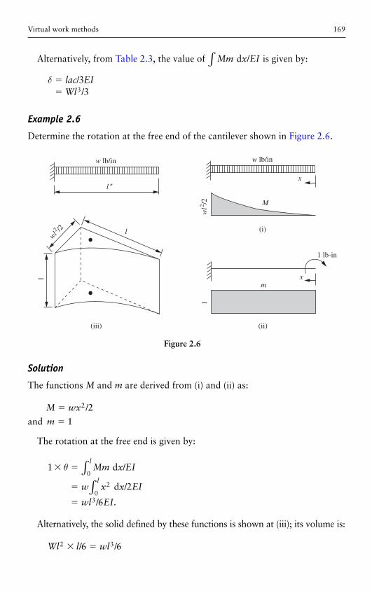
Example 2.6
Determine the rotation at the free end of the cantilever shown in Figure 2.6 .
w lb/in w lb/in
1 lb-in
wl2 /2
l �
l
M
m
(i)
(ii)(iii)
x
x1
1w
l2 /2
Figure 2.6
Solution
The functions M and m are derived from (i) and (ii) as:
M wx� 2 2/ and m � 1
The rotation at the free end is given by:
1
2
6
0
20
3
� �
�
�
θ Mm x EI
w x x EI
wl EI
l
l
d
d
/
/
/ .
∫∫
Alternatively, the solid defined by these functions is shown at (iii); its volume is:
Wl l wl2 36 6� �/ /
Structural Analysis: In Theory and Practice170
and the rotation at the free end is given by:
θ � wl EI3 6/ .
From Table 2.3 , the value of Mm x EI d /∫ is given by:
θ � � �
� � �
�
l c d e EIl wl wl EIwl EI
( ) /( / / )/
/
4 62 2 0 6
6
2 2
3
2.6 Solution of indeterminate structures
The principle of superposition may be defined as follows: the total displace-ments and internal stresses in a linear structure corresponding to a system of applied forces are the sum of the displacements and stresses corresponding to each load applied separately.
The principle of geometrical compatibility may be defined as follows: the displacement of any point in a structure due to a system of applied forces must be compatible with the deformations of the individual members.
The two above principles may be used to evaluate the redundants in indetermi-nate structures. The first stage in the analysis is to cut back the structure to a deter-minate condition and apply the external loads. The displacements corresponding to and at the point of application of the removed redundants may be determined by the virtual-work relations. To the unloaded cut-back structure, each redundant force is applied in turn and the displacements again determined. The total displace-ment at each point is the sum of the displacements due to the applied loads and the redundants and must be compatible with the deformations of the individual members. Thus, a series of compatibility equations is obtained equal in number to the number of redundants. These equations are solved simultaneously to obtain the redundants and the remaining forces obtained from equations of equilibrium.
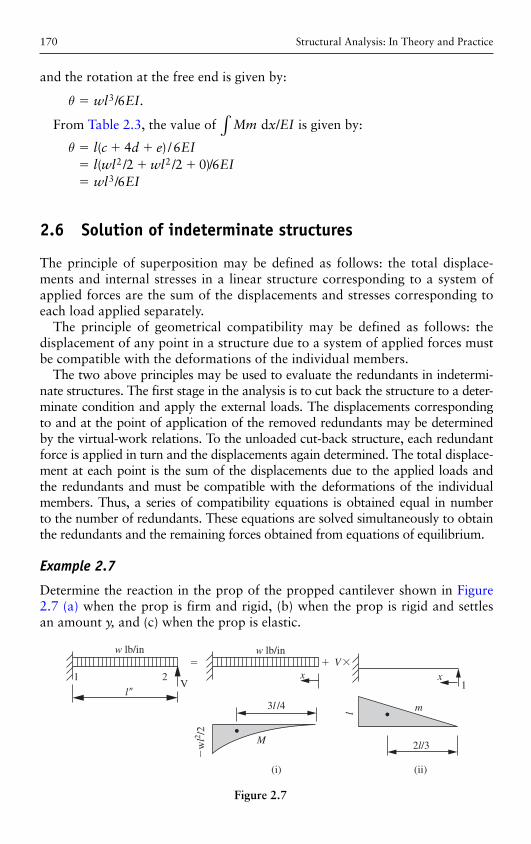
Example 2.7
Determine the reaction in the prop of the propped cantilever shown in Figure2.7 (a) when the prop is firm and rigid, (b) when the prop is rigid and settles an amount y, and (c) when the prop is elastic.
w lb/in w lb/inV�
l �
11
2V
� �x x
(i) (ii)
M
3l /4
l m
�w
l2 /2
2l/3
Figure 2.7
Virtual work methods 171
Solution
(a) The structure is one degree redundant, and the reaction in the prop is selected as the redundant and removed as shown at (i). The deflection of the free end of the cantilever in the line of action of V is:
′δ23
46 3 48
� � �
� �
wl l EIwl EI
/ //
To the cut-back structure, the redundant V is applied as shown at (ii). The deflec-tion of the free end of the cantilever in the line of action of V is:
′′δ22
32 2 33
� �
�
Vl l EIVl EI
/ //
The total deflection of 2 in the original structure is:
δ δ δ2 2 20
� �
�
′ ′′
Thus:
� � �wl EI Vl EI4 38 3 0/ /
and
V wl� 3 8/
(b) The total deflection of 2 in the original structure is:
δ δ δ2 2� �
� �
′ ′′2y
Thus:
� � � �wl EI Vl EI4 38 3/ / y
and
V / 3� �3 8 3wl EIy l/
(c) The total deflection of 2 in the original structure is:
δ δ δ2 2� �
� �
′ ′′2VL AE/
where L, A, and E are the length, cross-section, and modulus of elasticity of the prop.
Structural Analysis: In Theory and Practice172
Thus:
� � � �wl EI Vl EI VL AE4 38 3/ / /
and
V wl EI l EI L AE� �4 38 3/ ( / / )
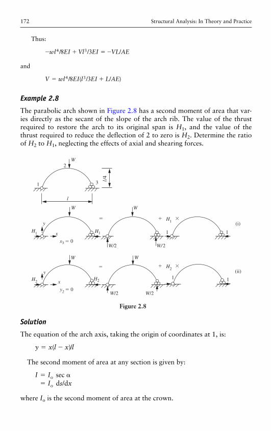
Example 2.8
The parabolic arch shown in Figure 2.8 has a second moment of area that var-ies directly as the secant of the slope of the arch rib. The value of the thrust required to restore the arch to its original span is H 1, and the value of the thrust required to reduce the deflection of 2 to zero is H 2. Determine the ratio of H 2 to H 1 , neglecting the effects of axial and shearing forces.
1
2
3
W
l
l/4
H1
y
x
x3 � 0
� � �
H1
W W
1 1
1 1
W/2
H1
� �H2
(i)
(ii)
W/2
H2
y
x
y2 � 0
�
H2
W W
W/2 W/2
Figure 2.8
Solution
The equation of the arch axis, taking the origin of coordinates at 1, is:
y x l x l� �( )/
The second moment of area at any section is given by:
I II s x
o
o
� ��
sec d /d
where I o is the second moment of area at the crown.
Virtual work methods 173
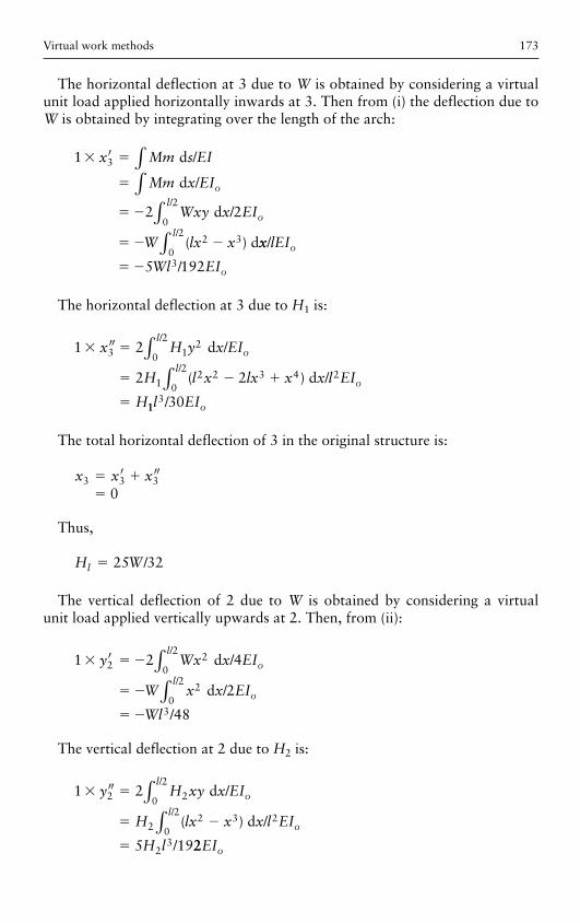
The horizontal deflection at 3 due to W is obtained by considering a virtual unit load applied horizontally inwards at 3. Then from (i) the deflection due to W is obtained by integrating over the length of the arch:
1
2 2
3
0
2
2 3
� �
�
� �
� � �
′ ∫∫
∫
x Mm s EI
Mm x EI
Wxy x EI
W lx x
o
o
l
d
d
d
d
/
/
/
( )
/
xx lEI
Wl EIo
l
o
/
/
/
0
2
35 192∫
� �
The horizontal deflection at 3 due to H 1 is:
1 2
2 2
3 12
0
2
12 2 3 4 2
0
2
� �
� � �
�
′′ ∫∫
x H y x EI
H l x lx x x l EI
H
o
l
o
l
d
d
/
( ) /
/
/
113 30l EIo/
The total horizontal deflection of 3 in the original structure is:
x x x3 3 30
� ��
′ ′′
Thus,
H Wl � 25 32/
The vertical deflection of 2 due to W is obtained by considering a virtual unit load applied vertically upwards at 2. Then, from (ii):
1 2 4
2
48
22
0
2
20
2
3
� � �
� �
� �
′ ∫∫
y Wx x EI
W x x EI
Wl
l
o
l
o
/
/
/
/
/
d
d
The vertical deflection at 2 due to H 2 is:
1 2
5 19
2 20
2
22 3 2
0
2
23
� �
� �
�
′′ ∫∫
y H xy x EI
H lx x x l EI
H l
o
l
o
l
d
d
/
/
( ) /
/
/
22EIo
Structural Analysis: In Theory and Practice174
The total vertical deflection of 2 in the original structure is:
y y y2 2 2 0� � �′ ′′
Thus,
H W2 4 5� /
and
H H2 1 128 1251 024
/ /.
��
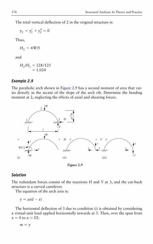
Example 2.9
The parabolic arch shown in Figure 2.9 has a second moment of area that var-ies directly as the secant of the slope of the arch rib. Determine the bending moment at 2, neglecting the effects of axial and shearing forces.
l
W
W
Wl/ 2
y� �H V
x
1 3
V
2W
H al2 /4
y y
x 1 x
(i) (ii) (iii)
� � �
1
Figure 2.9
Solution
The redundant forces consist of the reactions H and V at 3, and the cut-back structure is a curved cantilever.
The equation of the arch axis is:
y ax l x� �( )
The horizontal deflection of 3 due to condition (i) is obtained by considering a virtual-unit load applied horizontally inwards at 3. Then, over the span from x � 0 to x � l/ 2:
m y�
Virtual work methods 175
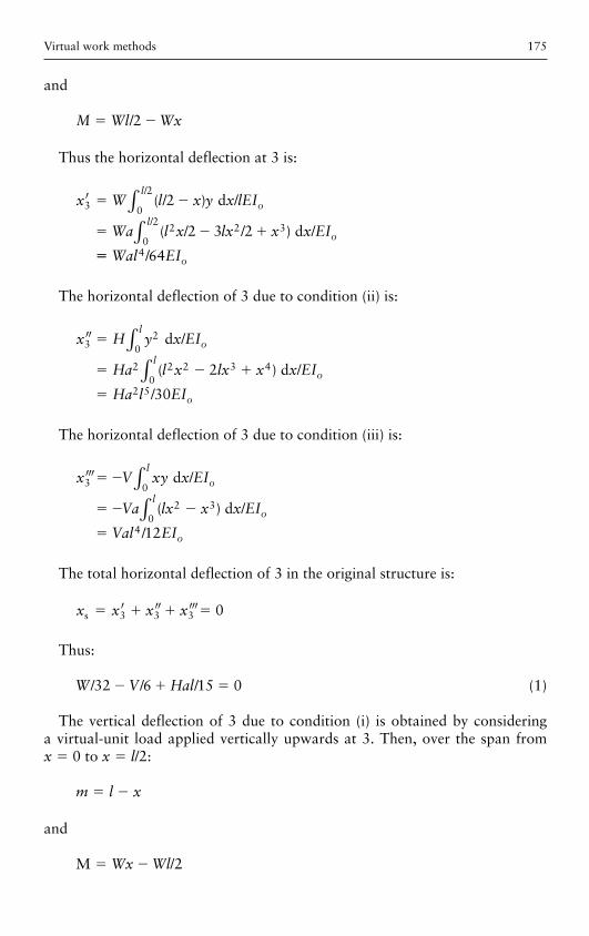
and
M Wl Wx� �/2
Thus the horizontal deflection at 3 is:
′ ∫∫
x W l x y x lEI
Wa l x lx x x EI
o
l
o
l
3 0
2
2 2 30
2
2
2 3 2
� �
� � �
( / ) /
( / / ) /
/
/
d
d
�� Wal EIo4 64/
The horizontal deflection of 3 due to condition (ii) is:
′′ ∫∫
x H y x EI
Ha l x lx x x EI
Ha l EI
o
l
o
l
o
32
0
2 2 2 3 40
2 5
2
30
�
� � �
�
d
d
/
( ) /
/
The horizontal deflection of 3 due to condition (iii) is:
′′′ ∫∫
x V xy x EI
Va lx x x EI
Val EI
o
l
o
l
o
3 0
2 30
4 12
� �
� � �
�
d
d
/
( ) /
/
The total horizontal deflection of 3 in the original structure is:
x x x xs � � � �′ ′′ ′′′3 3 3 0
Thus:
W V Hal/ / /32 6 15 0� � � (1)
The vertical deflection of 3 due to condition (i) is obtained by considering a virtual-unit load applied vertically upwards at 3. Then, over the span from x � 0 to x � l /2:
m l x� �
and
M /2� �Wx Wl
Structural Analysis: In Theory and Practice176
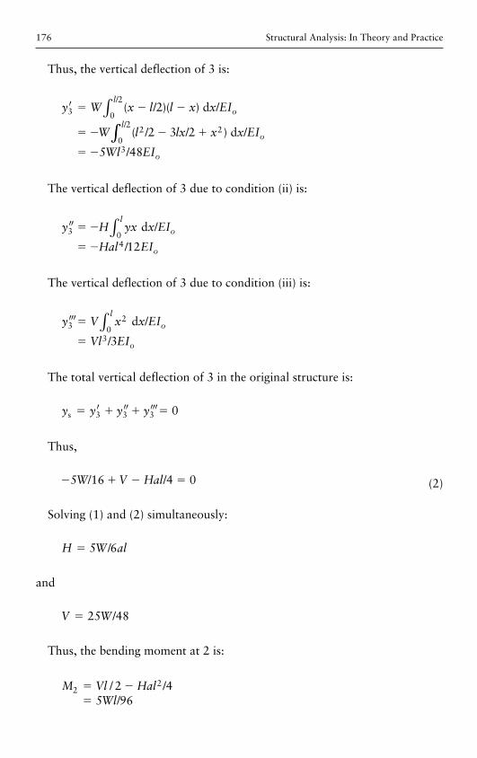
Thus, the vertical deflection of 3 is:
′ ∫y W x l l x x EI
W l lx x x EI
o
l
o
l
3 0
2
2 20
2
2
2 3 2
� � �
� � � �
( / )( ) /
( / / ) /
/
/
d
d∫∫� �5 483Wl EIo/
The vertical deflection of 3 due to condition (ii) is:
′′ ∫y H yx x EI
Hal EIo
l
o
3 04 12
� �
� �
d /
/
The vertical deflection of 3 due to condition (iii) is:
′′′ ∫y V x x EI
Vl EI
l
o
o
32
03 3
�
�
d /
/
The total vertical deflection of 3 in the original structure is:
y y y ys � � � �′ ′′ ′′′3 3 3 0
Thus,
� � � �5 16 4 0W V Hal/ / (2)
Solving (1) and (2) simultaneously:
H W al� 5 6/
and
V W� 25 48/
Thus, the bending moment at 2 is:
M Vl HalWl
222 4
5 96� ��
/ //
Virtual work methods 177
Supplementary problems
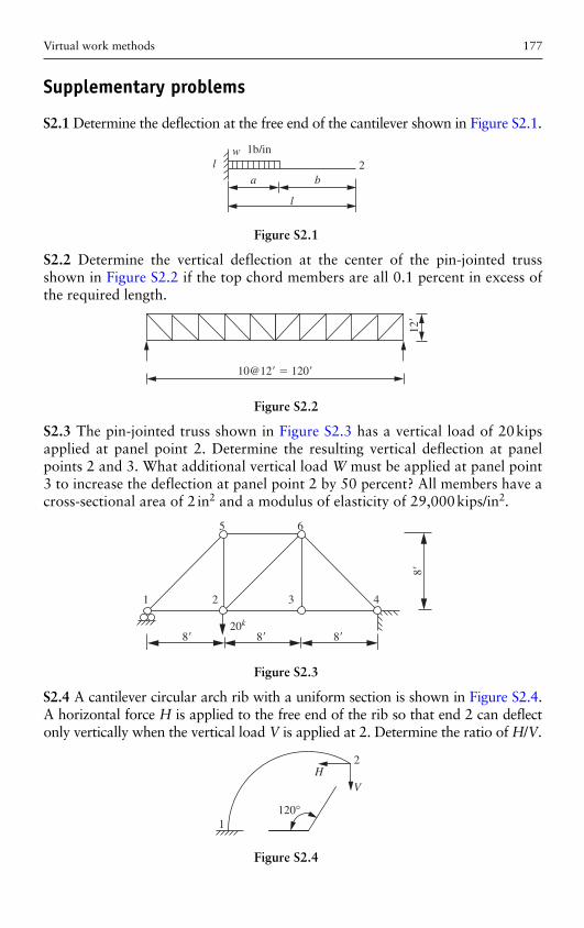
S2.1 Determine the deflection at the free end of the cantilever shown in Figure S2.1 .
w 1b/in
a b
l
l 2
Figure S2.1
10@12� � 120�
12�
Figure S2.2
1 2
8�20k
8� 8�
5 6
3 4
8�
Figure S2.3
S2.2 Determine the vertical deflection at the center of the pin-jointed truss shown in Figure S2.2 if the top chord members are all 0.1 percent in excess of the required length.
S2.3 The pin-jointed truss shown in Figure S2.3 has a vertical load of 20 kips applied at panel point 2. Determine the resulting vertical deflection at panel points 2 and 3. What additional vertical load W must be applied at panel point 3 to increase the deflection at panel point 2 by 50 percent? All members have a cross-sectional area of 2 in 2 and a modulus of elasticity of 29,000 kips/in 2 .
S2.4 A cantilever circular arch rib with a uniform section is shown in Figure S2.4 . A horizontal force H is applied to the free end of the rib so that end 2 can deflect only vertically when the vertical load V is applied at 2. Determine the ratio of H/V .
120°
HV
2
1
Figure S2.4
Structural Analysis: In Theory and Practice178
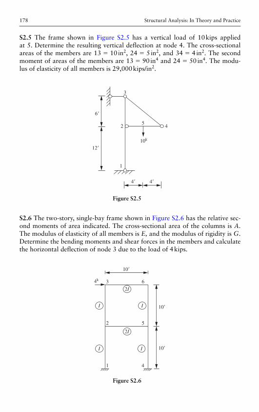
S2.5 The frame shown in Figure S2.5 has a vertical load of 10 kips applied at 5. Determine the resulting vertical deflection at node 4. The cross-sectional areas of the members are 13 � 10 in 2, 24 � 5 in 2, and 34 � 4 in 2. The second moment of areas of the members are 13 � 90 in 4 and 24 � 50 in 4. The modu-lus of elasticity of all members is 29,000 kips/in 2 .
1
12�
4� 4�
10k
6�
2
3
45
Figure S2.5
S2.6 The two-story, single-bay frame shown in Figure S2.6 has the relative sec-ond moments of area indicated. The cross-sectional area of the columns is A . The modulus of elasticity of all members is E, and the modulus of rigidity is G . Determine the bending moments and shear forces in the members and calculate the horizontal deflection of node 3 due to the load of 4 kips.
10�
10�
10�
1
2 5
4
2I
2I
3 6
II
I I
4k
Figure S2.6
Virtual work methods 179
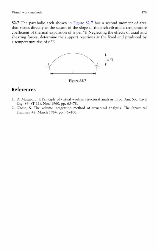
S2.7 The parabolic arch shown in Figure S2.7 has a second moment of area that varies directly as the secant of the slope of the arch rib and a temperature coefficient of thermal expansion of α per °F. Neglecting the effects of axial and shearing forces, determine the support reactions at the fixed end produced by a temperature rise of t °F.
l
1 2
al2/4
Figure S2.7
References
1. Di Maggio , I. F. Principle of virtual work in structural analysis . Proc. Am. Soc. Civil Eng. 86 ( ST 11 ) . Nov. 1960 . pp. 65 – 78 .
2. Ghose , S. The volume integration method of structural analysis . The Structural Engineer . 42 . March 1964 . pp. 95 – 100 .