Embed Size (px)
Citation preview
16 Instrument transformers | Medium voltage indoor
2. VOLTAGE TRANSFORMERSSupport typeSupport type with fuse Touch-proof type
17Instrument transformers | Medium voltage indoor
2. VOLTAGE TRANSFORMERS
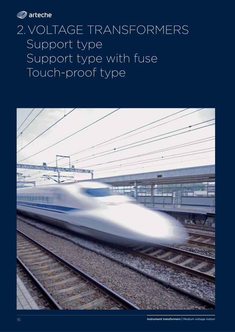
Voltage transformers reduce the voltage in the medium voltage line to proportional and manageable values, and separate the measuring instruments, meters, relays, etc. from the power circuit.
INTRODUCTION
1. Primary terminals2. Insulator (resin)3. Primary winding4. Magnetic core5. Secondary terminal box6. Base7. Earth terminal
SECTION
4
2
3
1
5
6
7
› Model VCL
Support type
Support type with fuse
Touch-proof type
18 Instrument transformers | Medium voltage indoor
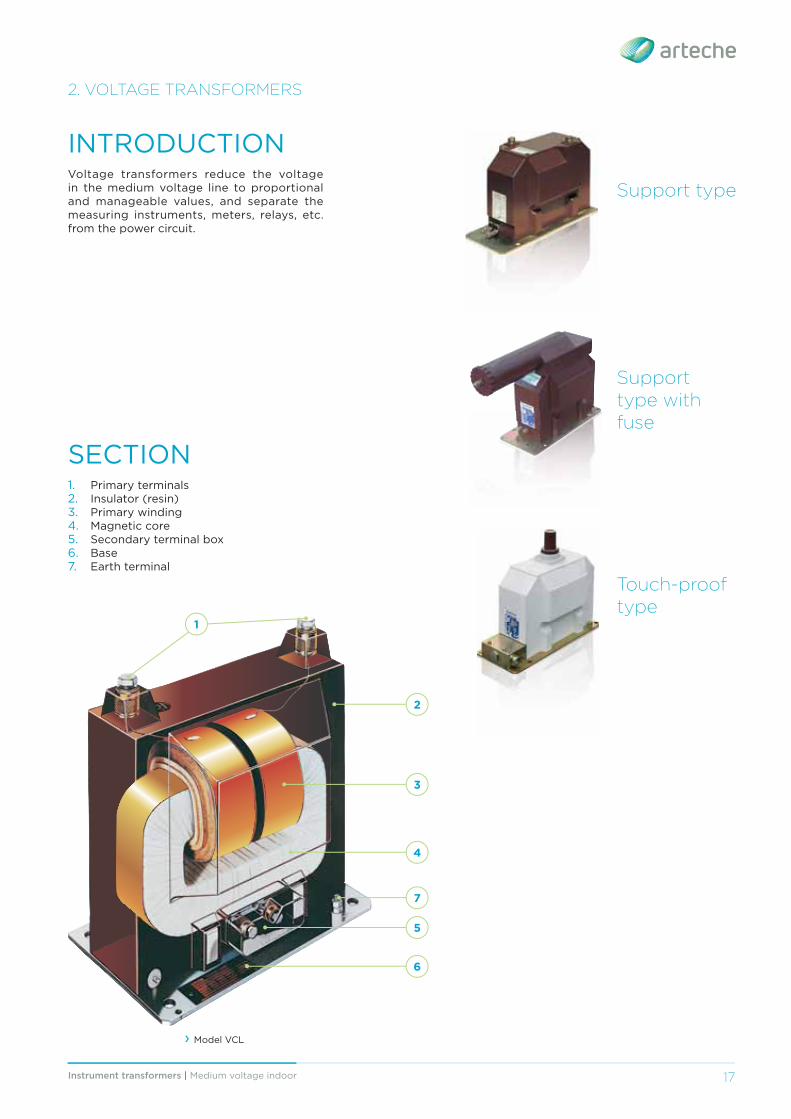
› UCL-24 Support type voltage transformer for medium voltage switchgears.
› UCL-7 Voltage transformer compartment in medium voltage switchgear.
› UCJF-24 Voltage transformer with integrated fuse; reduces the space needed in the switchgear.
19Instrument transformers | Medium voltage indoor
2. VOLTAGE TRANSFORMERS > Support type
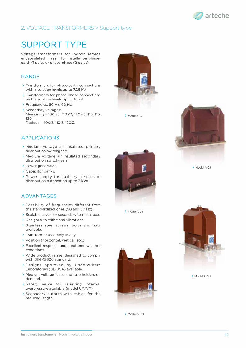
Voltage transformers for indoor service encapsulated in resin for installation phase-earth (1 pole) or phase-phase (2 poles).
RANGE
› Transformers for phase-earth connections with insulation levels up to 72.5 kV.
› Transformers for phase-phase connections with insulation levels up to 36 kV.
› Frequencies: 50 Hz, 60 Hz. › Secondary voltages: Measuring - 100:√3, 110:√3, 120:√3; 110, 115, 120. Residual - 100:3, 110:3, 120:3.
APPLICATIONS
› Medium voltage air insulated primary distribution switchgears.
› Medium voltage air insulated secondary distribution switchgears.
› Power generation. › Capacitor banks. › Power supply for auxiliary services or distribution automation up to 3 kVA.
ADVANTAGES
› Possibility of frequencies different from the standardized ones (50 and 60 Hz).
› Sealable cover for secondary terminal box. › Designed to withstand vibrations. › Stainless steel screws, bolts and nuts available.
› Transformer assembly in any › Position (horizontal, vertical, etc.) › Excellent response under extreme weather conditions.
› Wide product range, designed to comply with DIN 42600 standard.
› Designs approved by Underwriters Laboratories (UL-USA) available.
› Medium voltage fuses and fuse holders on demand.
› Safety valve for relieving internal overpressure available (model UX/VX).
› Secondary outputs with cables for the required length.
SUPPORT TYPE
› Model VCT
› Model UCI
› Model VCJ
› Model UCN
› Model VCN
Instrument transformers | Medium voltage indoor20
2. VOLTAGE TRANSFORMERS > Support type > Single phase
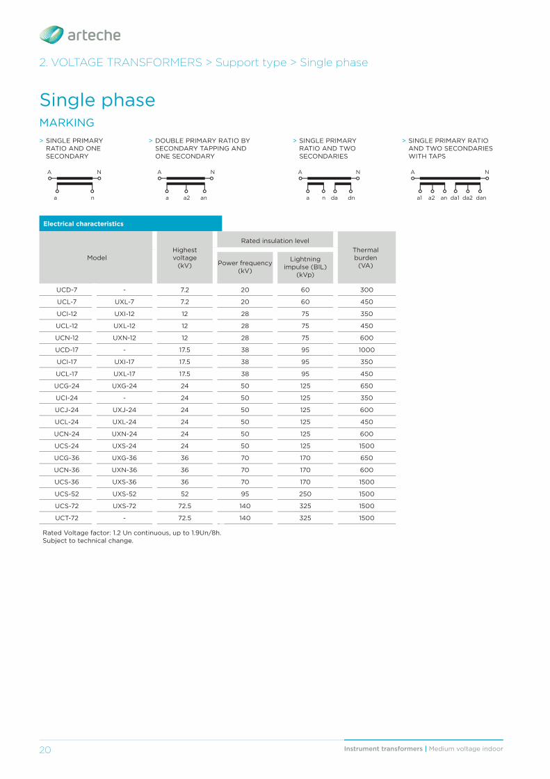
Electrical characteristics
ModelHighest voltage
(kV)
Rated insulation levelThermal burden
(VA)Power frequency (kV)
Lightning impulse (BIL)
(kVp)
UCD-7 - 7.2 20 60 300
UCL-7 UXL-7 7.2 20 60 450
UCI-12 UXI-12 12 28 75 350
UCL-12 UXL-12 12 28 75 450
UCN-12 UXN-12 12 28 75 600
UCD-17 - 17.5 38 95 1000
UCI-17 UXI-17 17.5 38 95 350
UCL-17 UXL-17 17.5 38 95 450
UCG-24 UXG-24 24 50 125 650
UCI-24 - 24 50 125 350
UCJ-24 UXJ-24 24 50 125 600
UCL-24 UXL-24 24 50 125 450
UCN-24 UXN-24 24 50 125 600
UCS-24 UXS-24 24 50 125 1500
UCG-36 UXG-36 36 70 170 650
UCN-36 UXN-36 36 70 170 600
UCS-36 UXS-36 36 70 170 1500
UCS-52 UXS-52 52 95 250 1500
UCS-72 UXS-72 72.5 140 325 1500
UCT-72 - 72.5 140 325 1500
Rated Voltage factor: 1.2 Un continuous, up to 1.9Un/8h.Subject to technical change.
Single phaseMARKING> SINGLE PRIMARY
RATIO AND ONE SECONDARY
> DOUBLE PRIMARY RATIO BY SECONDARY TAPPING AND ONE SECONDARY
a
A N
n a a2
A N
an
> SINGLE PRIMARY RATIO AND TWO SECONDARIES
a
A N
n dnda a1 da1a2 da2
A N
an dan
> SINGLE PRIMARY RATIO AND TWO SECONDARIES WITH TAPS
21Instrument transformers | Medium voltage indoor
2. VOLTAGE TRANSFORMERS > Support type > Single phase
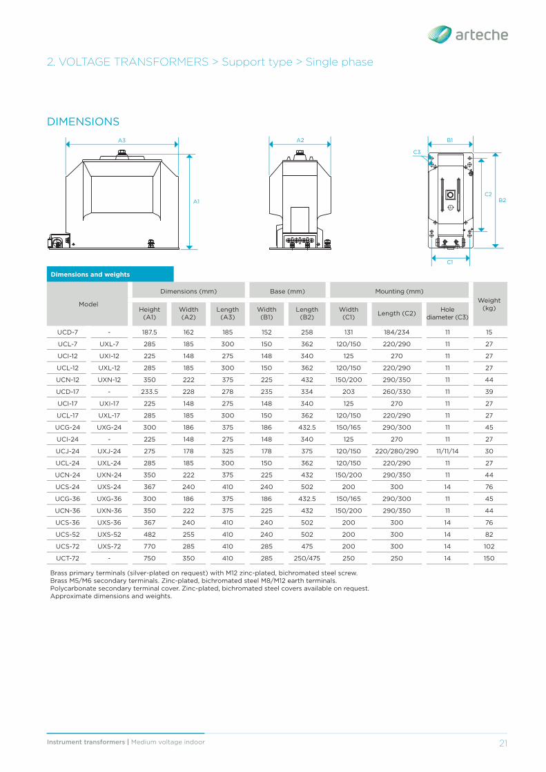
DIMENSIONS
Dimensions and weights
Model
Dimensions (mm) Base (mm) Mounting (mm)Weight
(kg)Height (A1)
Width (A2)
Length (A3)
Width (B1)
Length (B2)
Width (C1) Length (C2) Hole
diameter (C3)
UCD-7 - 187.5 162 185 152 258 131 184/234 11 15
UCL-7 UXL-7 285 185 300 150 362 120/150 220/290 11 27
UCI-12 UXI-12 225 148 275 148 340 125 270 11 27
UCL-12 UXL-12 285 185 300 150 362 120/150 220/290 11 27
UCN-12 UXN-12 350 222 375 225 432 150/200 290/350 11 44
UCD-17 - 233.5 228 278 235 334 203 260/330 11 39
UCI-17 UXI-17 225 148 275 148 340 125 270 11 27
UCL-17 UXL-17 285 185 300 150 362 120/150 220/290 11 27
UCG-24 UXG-24 300 186 375 186 432.5 150/165 290/300 11 45
UCI-24 - 225 148 275 148 340 125 270 11 27
UCJ-24 UXJ-24 275 178 325 178 375 120/150 220/280/290 11/11/14 30
UCL-24 UXL-24 285 185 300 150 362 120/150 220/290 11 27
UCN-24 UXN-24 350 222 375 225 432 150/200 290/350 11 44
UCS-24 UXS-24 367 240 410 240 502 200 300 14 76
UCG-36 UXG-36 300 186 375 186 432.5 150/165 290/300 11 45
UCN-36 UXN-36 350 222 375 225 432 150/200 290/350 11 44
UCS-36 UXS-36 367 240 410 240 502 200 300 14 76
UCS-52 UXS-52 482 255 410 240 502 200 300 14 82
UCS-72 UXS-72 770 285 410 285 475 200 300 14 102
UCT-72 - 750 350 410 285 250/475 250 250 14 150
Brass primary terminals (silver-plated on request) with M12 zinc-plated, bichromated steel screw. Brass M5/M6 secondary terminals. Zinc-plated, bichromated steel M8/M12 earth terminals.Polycarbonate secondary terminal cover. Zinc-plated, bichromated steel covers available on request.Approximate dimensions and weights.
A
A2 B1
C1
A3
A1 B2C2
C3
Instrument transformers | Medium voltage indoor22
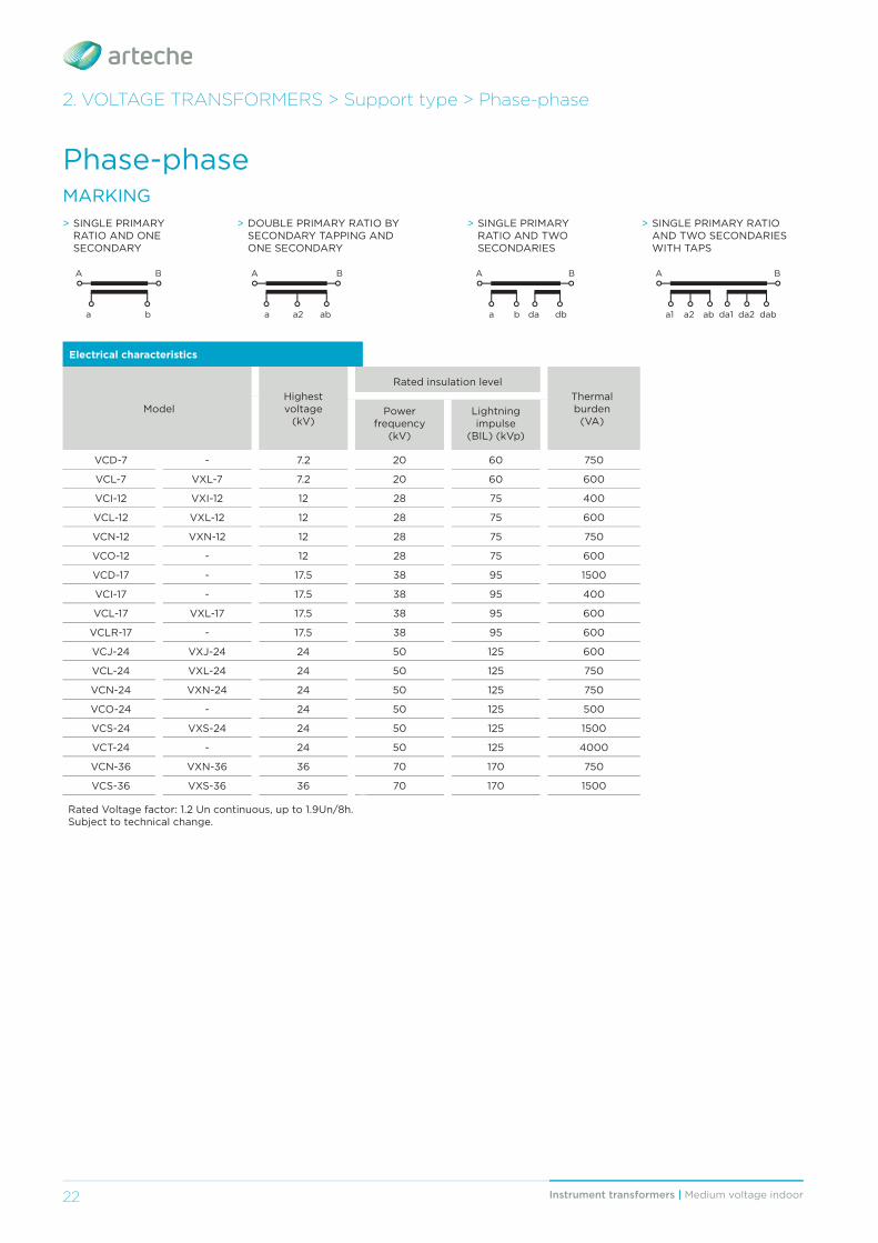
> SINGLE PRIMARY RATIO AND ONE SECONDARY
a
A B
b
> DOUBLE PRIMARY RATIO BY SECONDARY TAPPING AND ONE SECONDARY
a a2
A B
ab
> SINGLE PRIMARY RATIO AND TWO SECONDARIES
a
A B
b dbda a1 da1a2 da2
A B
ab dab
> SINGLE PRIMARY RATIO AND TWO SECONDARIES WITH TAPS
2. VOLTAGE TRANSFORMERS > Support type > Phase-phase
Electrical characteristics
ModelHighest voltage
(kV)
Rated insulation levelThermal burden
(VA)Power
frequency (kV)
Lightning impulse
(BIL) (kVp)
VCD-7 - 7.2 20 60 750
VCL-7 VXL-7 7.2 20 60 600
VCI-12 VXI-12 12 28 75 400
VCL-12 VXL-12 12 28 75 600
VCN-12 VXN-12 12 28 75 750
VCO-12 - 12 28 75 600
VCD-17 - 17.5 38 95 1500
VCI-17 - 17.5 38 95 400
VCL-17 VXL-17 17.5 38 95 600
VCLR-17 - 17.5 38 95 600
VCJ-24 VXJ-24 24 50 125 600
VCL-24 VXL-24 24 50 125 750
VCN-24 VXN-24 24 50 125 750
VCO-24 - 24 50 125 500
VCS-24 VXS-24 24 50 125 1500
VCT-24 - 24 50 125 4000
VCN-36 VXN-36 36 70 170 750
VCS-36 VXS-36 36 70 170 1500
Rated Voltage factor: 1.2 Un continuous, up to 1.9Un/8h.Subject to technical change.
Phase-phaseMARKING
23Instrument transformers | Medium voltage indoor
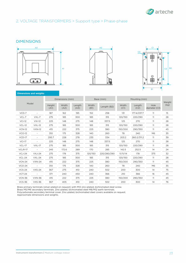
2. VOLTAGE TRANSFORMERS > Support type > Phase-phase
DIMENSIONS
Dimensions and weights
Model
Dimensions (mm) Base (mm) Mounting (mm)Weight
(kg)Height (A1)
Width (A2)
Length (A3)
Width (B1) Length (B2) Width
(C1)Length
(C2)Hole
diameter (C3)
VCD-7 - 187 162 195 152 258 131 177.4/237.7 11 15
VCL-7 VXL-7 275 185 300 185 315 120/150 220/290 11 28
VCI-12 VXI-12 225 148 275 148 337.5 125 270 11 28
VCL-12 VXL-12 275 185 300 185 315 120/150 220/290 11 28
VCN-12 VXN-12 415 222 375 225 380 150/200 290/350 11 45
VCO-12 - 310 175 328 140 260 78 240 M6 35
VCD-17 - 295.7 228 278 235 334 203.2 260.2/311.2 11 39
VCI-17 - 225 148 275 148 337.5 125 270 11 28
VCL-17 VXL-17 275 185 300 185 315 120/150 220/290 11 28
VCLR-17 - 245 172.6 289 170 285 142.5 252.5 14 24
VCJ-24 VXJ-24 275 178 375 120/150 220/280/290 11/11/14 178 375 32
VCL-24 VXL-24 275 185 300 185 315 120/150 220/290 11 28
VCN-24 VXN-24 415 222 375 225 380 150/200 290/350 11 45
VCO-24 - 310 175 328 140 260 78 240 M6 35
VCS-24 VXS-24 367 275 410 240 502 200 300 14 75
VCT-24 - 371 240 450 240 366 210 366 16 45
VCN-36 VXN-36 415 222 375 225 380 150/200 290/350 11 45
VCS-36 VXS-36 367 405 410 240 502 200 300 14 76
Brass primary terminals (silver-plated on request) with M12 zinc-plated, bichromated steel screw. Brass M5/M6 secondary terminals. Zinc-plated, bichromated steel M8/M12 earth terminals.Polycarbonate secondary terminal cover. Zinc-plated, bichromated steel covers available on request.Approximate dimensions and weights.
AB
A2 C1
B1
A3
A1 B2C2
C3
Instrument transformers | Medium voltage indoor24
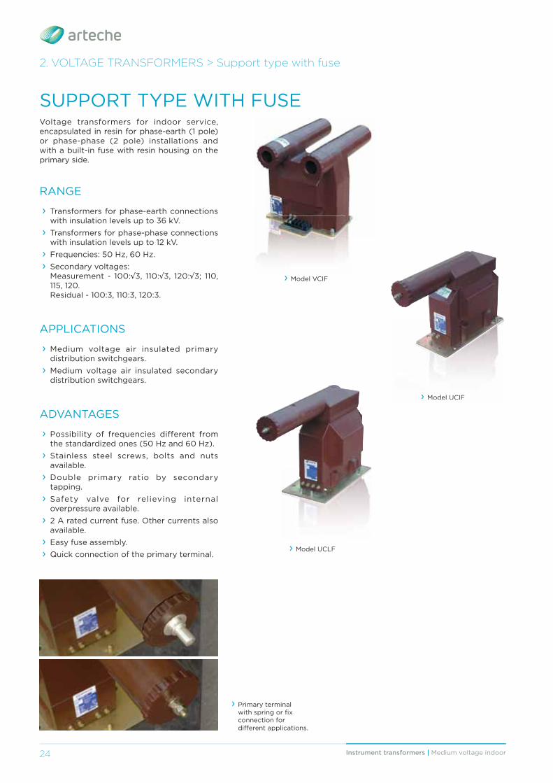
2. VOLTAGE TRANSFORMERS > Support type with fuse
Voltage transformers for indoor service, encapsulated in resin for phase-earth (1 pole) or phase-phase (2 pole) installations and with a built-in fuse with resin housing on the primary side.
RANGE
› Transformers for phase-earth connections with insulation levels up to 36 kV.
› Transformers for phase-phase connections with insulation levels up to 12 kV.
› Frequencies: 50 Hz, 60 Hz. › Secondary voltages: Measurement - 100:√3, 110:√3, 120:√3; 110, 115, 120. Residual - 100:3, 110:3, 120:3.
APPLICATIONS
› Medium voltage air insulated primary distribution switchgears.
› Medium voltage air insulated secondary distribution switchgears.
ADVANTAGES
› Possibility of frequencies different from the standardized ones (50 Hz and 60 Hz).
› Stainless steel screws, bolts and nuts available.
› Double primary ratio by secondary tapping.
› Safety valve for relieving internal overpressure available.
› 2 A rated current fuse. Other currents also available.
› Easy fuse assembly. › Quick connection of the primary terminal.
SUPPORT TYPE WITH FUSE
› Primary terminal with spring or fi x connection for diff erent applications.
› Model VCIF
› Model UCIF› Model UCIF
› Model UCLF
25Instrument transformers | Medium voltage indoor
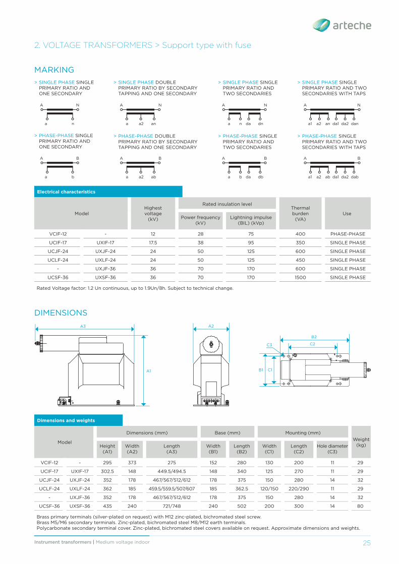
2. VOLTAGE TRANSFORMERS > Support type with fuse
DIMENSIONS
> PHASE-PHASE SINGLE PRIMARY RATIO AND ONE SECONDARY
a
A B
b
> PHASE-PHASE DOUBLE PRIMARY RATIO BY SECONDARY TAPPING AND ONE SECONDARY
a a2
A B
ab
> PHASE-PHASE SINGLE PRIMARY RATIO AND TWO SECONDARIES
a
A B
b dbda a1 da1a2 da2
A B
ab dab
> PHASE-PHASE SINGLE PRIMARY RATIO AND TWO SECONDARIES WITH TAPS
MARKING> SINGLE PHASE SINGLE
PRIMARY RATIO AND ONE SECONDARY
> SINGLE PHASE DOUBLE PRIMARY RATIO BY SECONDARY TAPPING AND ONE SECONDARY
a
A N
n a a2
A N
an
> SINGLE PHASE SINGLE PRIMARY RATIO AND TWO SECONDARIES
a
A N
n dnda a1 da1a2 da2
A N
an dan
> SINGLE PHASE SINGLE PRIMARY RATIO AND TWO SECONDARIES WITH TAPS
Dimensions and weights
Model
Dimensions (mm) Base (mm) Mounting (mm)Weight
(kg)Height (A1)
Width (A2)
Length (A3)
Width (B1)
Length (B2)
Width (C1)
Length (C2)
Hole diameter (C3)
VCIF-12 - 295 373 275 152 280 130 200 11 29
UCIF-17 UXIF-17 302.5 148 449.5/494.5 148 340 125 270 11 29
UCJF-24 UXJF-24 352 178 467/567/512/612 178 375 150 280 14 32
UCLF-24 UXLF-24 362 185 459.5/559.5/507/607 185 362.5 120/150 220/290 11 29
- UXJF-36 352 178 467/567/512/612 178 375 150 280 14 32
UCSF-36 UXSF-36 435 240 721/748 240 502 200 300 14 80
Brass primary terminals (silver-plated on request) with M12 zinc-plated, bichromated steel screw. Brass M5/M6 secondary terminals. Zinc-plated, bichromated steel M8/M12 earth terminals.Polycarbonate secondary terminal cover. Zinc-plated, bichromated steel covers available on request. Approximate dimensions and weights.
Electrical characteristics
ModelHighestvoltage
(kV)
Rated insulation levelThermal burden
(VA)Use
Power frequency (kV)
Lightning impulse (BIL) (kVp)
VCIF-12 - 12 28 75 400 PHASE-PHASE
UCIF-17 UXIF-17 17.5 38 95 350 SINGLE PHASE
UCJF-24 UXJF-24 24 50 125 600 SINGLE PHASE
UCLF-24 UXLF-24 24 50 125 450 SINGLE PHASE
- UXJF-36 36 70 170 600 SINGLE PHASE
UCSF-36 UXSF-36 36 70 170 1500 SINGLE PHASE
Rated Voltage factor: 1.2 Un continuous, up to 1.9Un/8h. Subject to technical change.
A2
C1B1
A3
A1
B2
C2C3
Instrument transformers | Medium voltage indoor26
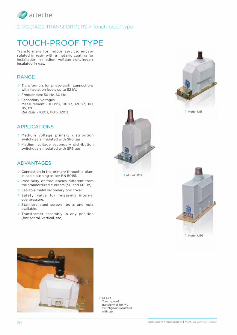
2. VOLTAGE TRANSFORMERS > Touch-proof type
Transformers for indoor service, encap-sulated in resin with a metallic coating for installation in medium voltage switchgears insulated in gas.
RANGE
› Transformers for phase-earth connections with insulation levels up to 52 kV.
› Frequencies: 50 Hz, 60 Hz. › Secondary voltages: Measurement - 100:√3, 110:√3, 120:√3; 110, 115, 120. Residual - 100:3, 110:3, 120:3.
APPLICATIONS
› Medium voltage primary distribution switchgears insulated with SF6 gas.
› Medium voltage secondary distribution switchgears insulated with SF6 gas
ADVANTAGES
› Connection in the primary through a plug-in cable bushing as per EN 50181.
› Possibility of frequencies different from the standardized currents (50 and 60 Hz).
› Sealable metal secondary box cover. › Safety valve for releasing internal overpressure.
› Stainless steel screws, bolts and nuts available.
› Transformer assembly in any position (horizontal, vertical, etc).
TOUCH-PROOF TYPE
› UEI-24 Touch-proof transformer for MV switchgears insulated with gas.
› Model UEG
› Model UEN
› Model UEI
27Instrument transformers | Medium voltage indoor
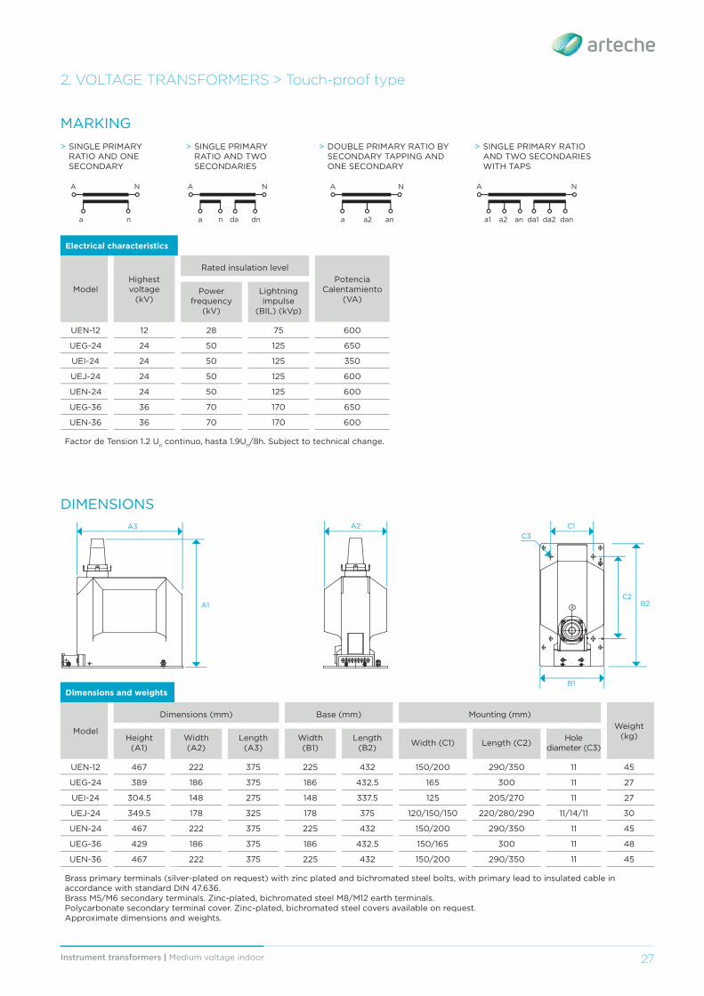
2. VOLTAGE TRANSFORMERS > Touch-proof type
Dimensions and weights
Model
Dimensions (mm) Base (mm) Mounting (mm)Weight
(kg)Height (A1)
Width (A2)
Length (A3)
Width (B1)
Length (B2) Width (C1) Length (C2) Hole
diameter (C3)
UEN-12 467 222 375 225 432 150/200 290/350 11 45
UEG-24 389 186 375 186 432.5 165 300 11 27
UEI-24 304.5 148 275 148 337.5 125 205/270 11 27
UEJ-24 349.5 178 325 178 375 120/150/150 220/280/290 11/14/11 30
UEN-24 467 222 375 225 432 150/200 290/350 11 45
UEG-36 429 186 375 186 432.5 150/165 300 11 48
UEN-36 467 222 375 225 432 150/200 290/350 11 45
Brass primary terminals (silver-plated on request) with zinc plated and bichromated steel bolts, with primary lead to insulated cable in accordance with standard DIN 47.636.Brass M5/M6 secondary terminals. Zinc-plated, bichromated steel M8/M12 earth terminals.Polycarbonate secondary terminal cover. Zinc-plated, bichromated steel covers available on request.Approximate dimensions and weights.
Electrical characteristics
ModelHighest voltage
(kV)
Rated insulation levelPotencia
Calentamiento(VA)
Power frequency
(kV)
Lightning impulse
(BIL) (kVp)
UEN-12 12 28 75 600
UEG-24 24 50 125 650
UEI-24 24 50 125 350
UEJ-24 24 50 125 600
UEN-24 24 50 125 600
UEG-36 36 70 170 650
UEN-36 36 70 170 600
Factor de Tension 1.2 Un continuo, hasta 1.9Un/8h. Subject to technical change.
DIMENSIONS
MARKING> SINGLE PRIMARY
RATIO AND ONE SECONDARY
a
A N
n
> SINGLE PRIMARY RATIO AND TWO SECONDARIES
a
A N
n dnda
> DOUBLE PRIMARY RATIO BY SECONDARY TAPPING AND ONE SECONDARY
a a2
A N
an a1 da1a2 da2
A N
an dan
> SINGLE PRIMARY RATIO AND TWO SECONDARIES WITH TAPS
A
A2 C1
B1
A3
A1 B2C2
C3