Embed Size (px)
Citation preview
Service Training
Self Study Program 826803
2.0 Liter TDI Common Rail BIN5 ULEV Engine
Cover art fi le number tbd
Volkswagen of America, Inc.Volkswagen AcademyPrinted in U.S.A.Printed 4/2008Course Number 826803
©2008 Volkswagen of America, Inc.
All rights reserved. All information contained in this manual is based on the latest information available at the time of printing and is subject to the copyright and other intellectual property rights of Volkswagen of America, Inc., its affi liated companies and its licensors. All rights are reserved to make changes at any time without notice. No part of this document may be reproduced, stored in a retrieval system, or transmitted in any form or by any means, electronic, mechanical, photocopying, recording or otherwise, nor may these materials be modifi ed or reposted to other sites without the prior expressed written permission of the publisher.
All requests for permission to copy and redistribute information should be referred to Volkswagen of America, Inc.
Always check Technical Bulletins and the latest electronic repair information for information that may supersede any information included in this booklet.
Trademarks: All brand names and product names used in this manual are trade names, service marks, trademarks, or registered trademarks; and are the property of their respective owners.
iii
Contents
This Self-Study Program provides information regarding the design and function of new models.This Self-Study Program is not a Repair Manual.
This information will not be updated.For maintenance and repair procedures, always refer to the latest electronic service information.
Note Important!
Introduction . . . . . . . . . . . . . . . . . . . . . . . . . . . . . . . . . . . . . . . . 1
Overview . . . . . . . . . . . . . . . . . . . . . . . . . . . . . . . . . . . . . . . . . . 3
Engine Mechanics . . . . . . . . . . . . . . . . . . . . . . . . . . . . . . . . . . . . 5
Engine Management System . . . . . . . . . . . . . . . . . . . . . . . . . . . . 44
Service . . . . . . . . . . . . . . . . . . . . . . . . . . . . . . . . . . . . . . . . . . 68
Knowledge Assessment . . . . . . . . . . . . . . . . . . . . . . . . . . . . . . . 73

Page intentionally left blank
1
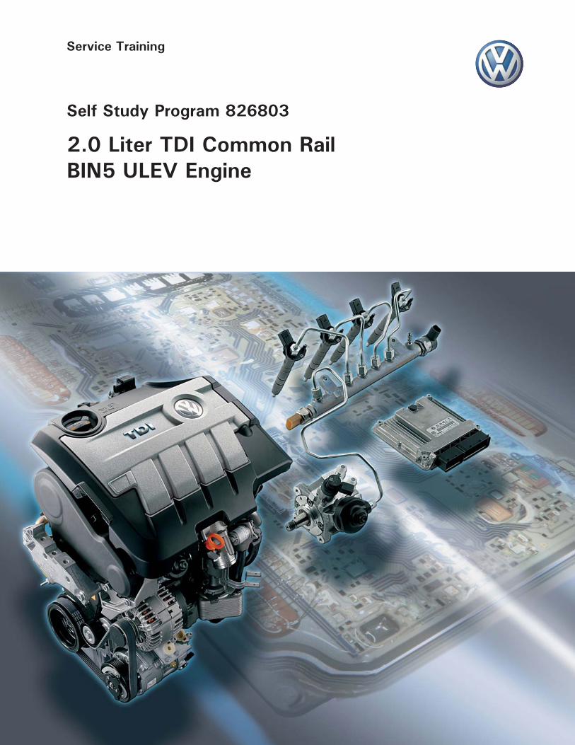
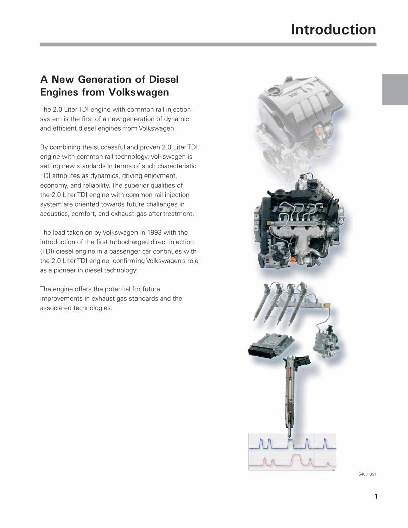
IntroductionIntroduction
A New Generation of Diesel Engines from Volkswagen
The 2.0 Liter TDI engine with common rail injection system is the fi rst of a new generation of dynamic and effi cient diesel engines from Volkswagen.
By combining the successful and proven 2.0 Liter TDI engine with common rail technology, Volkswagen is setting new standards in terms of such characteristic TDI attributes as dynamics, driving enjoyment, economy, and reliability. The superior qualities of the 2.0 Liter TDI engine with common rail injection system are oriented towards future challenges in acoustics, comfort, and exhaust gas after-treatment.
The lead taken on by Volkswagen in 1993 with the introduction of the fi rst turbocharged direct injection (TDI) diesel engine in a passenger car continues with the 2.0 Liter TDI engine, confi rming Volkswagen’s role as a pioneer in diesel technology.
The engine offers the potential for future improvements in exhaust gas standards and the associated technologies.
S403_051

2
Notes
3
OverviewOverview
Heritage
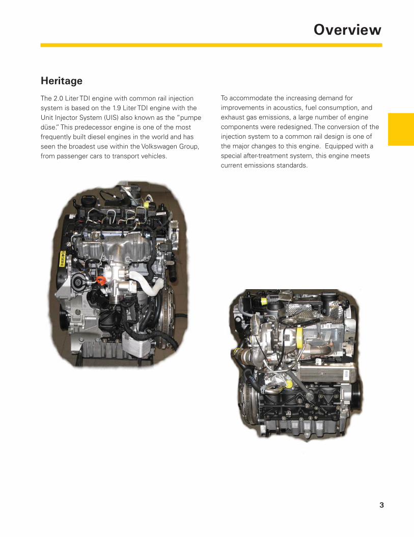
The 2.0 Liter TDI engine with common rail injection system is based on the 1.9 Liter TDI engine with the Unit Injector System (UIS) also known as the “pumpe düse.” This predecessor engine is one of the most frequently built diesel engines in the world and has seen the broadest use within the Volkswagen Group, from passenger cars to transport vehicles.
To accommodate the increasing demand for improvements in acoustics, fuel consumption, and exhaust gas emissions, a large number of engine components were redesigned. The conversion of the injection system to a common rail design is one of the major changes to this engine. Equipped with a special after-treatment system, this engine meets current emissions standards.
4
Overview
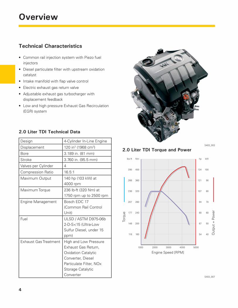
Technical Characteristics
Common rail injection system with Piezo fuel injectors
Diesel particulate fi lter with upstream oxidation catalyst
Intake manifold with fl ap valve control
Electric exhaust gas return valve
Adjustable exhaust gas turbocharger with displacement feedback
Low and high pressure Exhaust Gas Recirculation (EGR) system
•
•
•
•
•
•
S403_003
2.0 Liter TDI Torque and Power
2.0 Liter TDI Technical Data
Design 4-Cylinder In-Line Engine
Displacement 120 in3 (1968 cm3)
Bore 3.189 in. (81 mm)
Stroke 3.760 in. (95.5 mm)
Valves per Cylinder 4
Compression Ratio 16.5:1
Maximum Output 140 hp (103 kW) at 4000 rpm
Maximum Torque 236 lb-ft (320 Nm) at 1750 rpm up to 2500 rpm
Engine Management Bosch EDC 17 (Common Rail Control Unit)
Fuel ULSD / ASTM D975-06b 2-D-S<15 (Ultra-Low Sulfur Diesel, under 15 ppm)
Exhaust Gas Treatment High and Low Pressure Exhaust Gas Return, Oxidation Catalytic Converter, Diesel Particulate Filter, NOx Storage Catalytic Converter
S403_007
Engine Speed [RPM]
1000 2000 3000 4000 5000
lbs-ft Nm
295 400
266 360
236 320
207 280
177 240
148 200
118 160
Torq
ue
hp kW
134 100
121 90
107 80
94 70
80 60
67 50
54 40 Out
put
= P
ower
5
Engine MechanicsEngine Mechanics
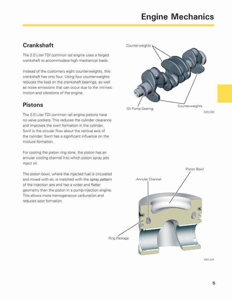
Crankshaft
The 2.0 Liter TDI common rail engine uses a forged crankshaft to accommodate high mechanical loads.
Instead of the customary eight counterweights, this crankshaft has only four. Using four counterweights reduces the load on the crankshaft bearings, as well as noise emissions that can occur due to the intrinsic motion and vibrations of the engine.
Pistons
The 2.0 Liter TDI common rail engine pistons have no valve pockets. This reduces the cylinder clearance and improves the swirl formation in the cylinder. Swirl is the circular fl ow about the vertical axis of the cylinder. Swirl has a signifi cant infl uence on the mixture formation.
For cooling the piston ring zone, the piston has an annular cooling channel into which piston spray jets inject oil.
The piston bowl, where the injected fuel is circulated and mixed with air, is matched with the spray pattern of the injection jets and has a wider and fl atter geometry than the piston in a pump-injection engine. This allows more homogeneous carburation and reduces soot formation.
S403_069
Counterweights
Oil Pump GearingCounterweights
S403_004
Piston Bowl
Annular Channel
Ring Package
6
Engine Mechanics
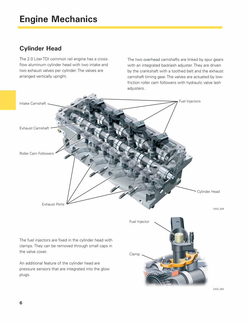
Cylinder Head
The 2.0 Liter TDI common rail engine has a cross-fl ow aluminum cylinder head with two intake and two exhaust valves per cylinder. The valves are arranged vertically upright.
The fuel injectors are fi xed in the cylinder head with clamps. They can be removed through small caps in the valve cover.
An additional feature of the cylinder head are pressure sensors that are integrated into the glow plugs.
S403_084
S403_008
The two overhead camshafts are linked by spur gears with an integrated backlash adjuster. They are driven by the crankshaft with a toothed belt and the exhaust camshaft timing gear. The valves are actuated by low-friction roller cam followers with hydraulic valve lash adjusters.
Fuel Injector
Clamp
Cylinder Head
Fuel Injectors
Exhaust Ports
Roller Cam Followers
Exhaust Camshaft
Intake Camshaft
7
Engine Mechanics
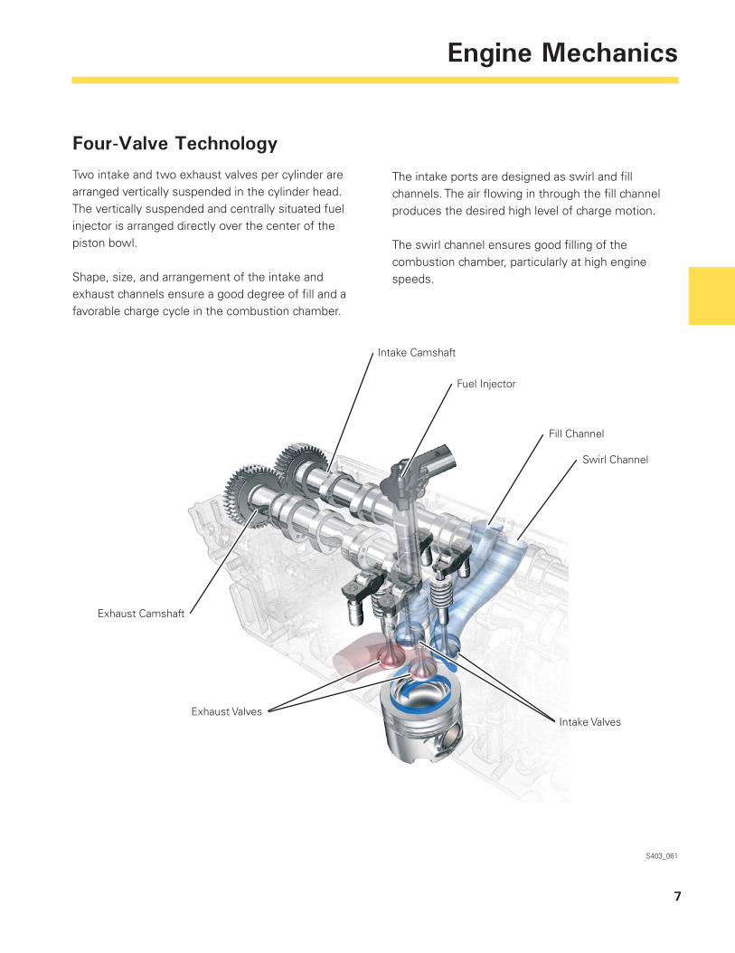
Four-Valve Technology
Two intake and two exhaust valves per cylinder are arranged vertically suspended in the cylinder head. The vertically suspended and centrally situated fuel injector is arranged directly over the center of the piston bowl.
Shape, size, and arrangement of the intake and exhaust channels ensure a good degree of fi ll and a favorable charge cycle in the combustion chamber.
S403_061
The intake ports are designed as swirl and fi ll channels. The air fl owing in through the fi ll channel produces the desired high level of charge motion.
The swirl channel ensures good fi lling of the combustion chamber, particularly at high engine speeds.
Intake Camshaft
Exhaust Camshaft
Exhaust Valves
Fuel Injector
Fill Channel
Swirl Channel
Intake Valves
8
Engine Mechanics
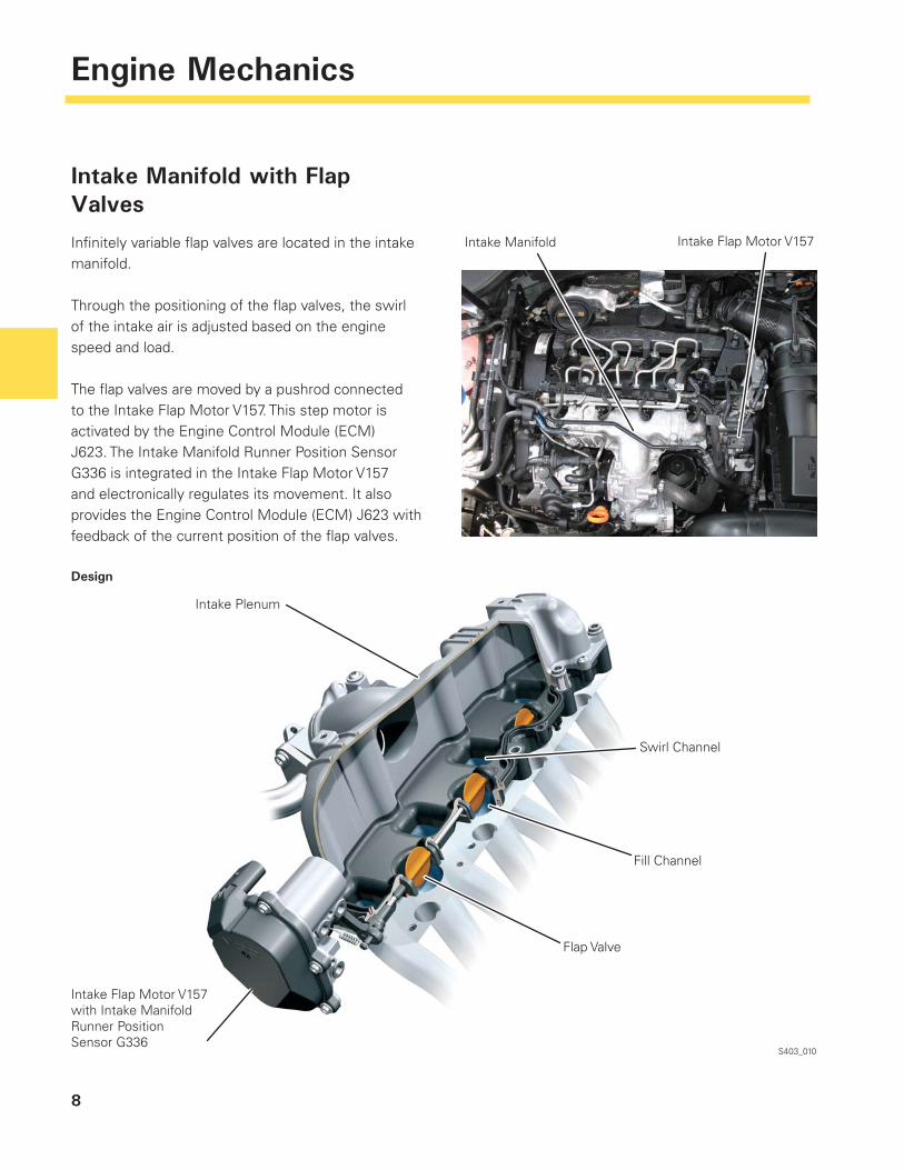
Intake Manifold with Flap Valves
Infi nitely variable fl ap valves are located in the intake manifold.
Through the positioning of the fl ap valves, the swirl of the intake air is adjusted based on the engine speed and load.
The fl ap valves are moved by a pushrod connected to the Intake Flap Motor V157. This step motor is activated by the Engine Control Module (ECM) J623. The Intake Manifold Runner Position Sensor G336 is integrated in the Intake Flap Motor V157 and electronically regulates its movement. It also provides the Engine Control Module (ECM) J623 with feedback of the current position of the fl ap valves.
Intake Flap Motor V157
Design
S403_010
Intake Manifold
Intake Plenum
Intake Flap Motor V157 with Intake Manifold Runner Position Sensor G336
Swirl Channel
Fill Channel
Flap Valve
9
Engine Mechanics
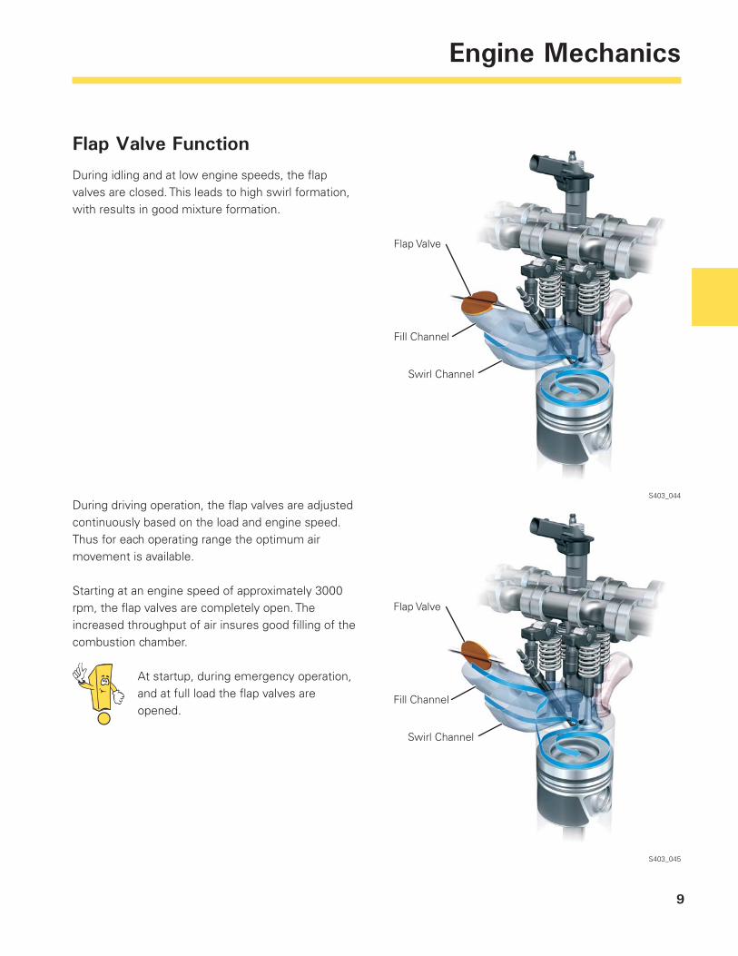
During driving operation, the fl ap valves are adjusted continuously based on the load and engine speed. Thus for each operating range the optimum air movement is available.
Starting at an engine speed of approximately 3000 rpm, the fl ap valves are completely open. The increased throughput of air insures good fi lling of the combustion chamber.
At startup, during emergency operation, and at full load the fl ap valves are opened.
Flap Valve Function
During idling and at low engine speeds, the fl ap valves are closed. This leads to high swirl formation, with results in good mixture formation.
S403_044
S403_045
Flap Valve
Fill Channel
Swirl Channel
Flap Valve
Fill Channel
Swirl Channel
10
Engine Mechanics
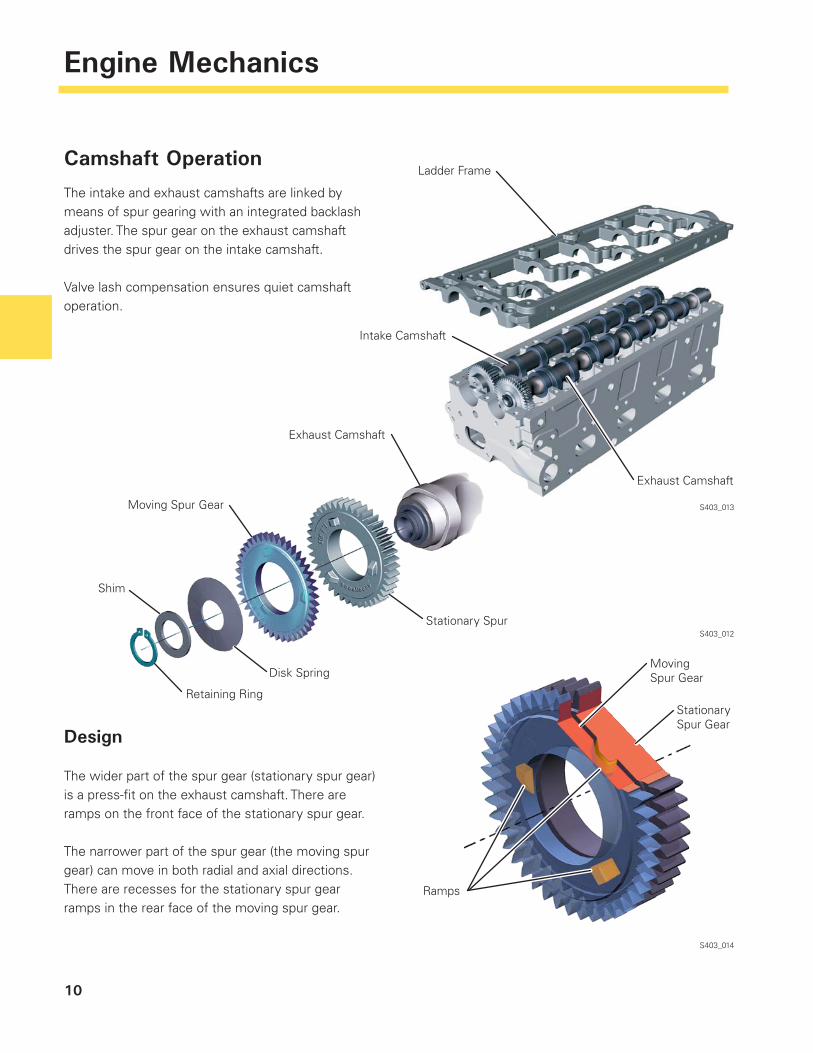
Camshaft Operation
The intake and exhaust camshafts are linked by means of spur gearing with an integrated backlash adjuster. The spur gear on the exhaust camshaft drives the spur gear on the intake camshaft.
Valve lash compensation ensures quiet camshaft operation.
S403_013
S403_012
S403_014
Design
The wider part of the spur gear (stationary spur gear) is a press-fi t on the exhaust camshaft. There are ramps on the front face of the stationary spur gear.
The narrower part of the spur gear (the moving spur gear) can move in both radial and axial directions. There are recesses for the stationary spur gear ramps in the rear face of the moving spur gear.
Ladder Frame
Intake Camshaft
Exhaust Camshaft
Exhaust Camshaft
Moving Spur Gear
Shim
Retaining Ring
Disk Spring
Stationary Spur
Moving Spur Gear
Stationary Spur Gear
Ramps
11
Engine Mechanics
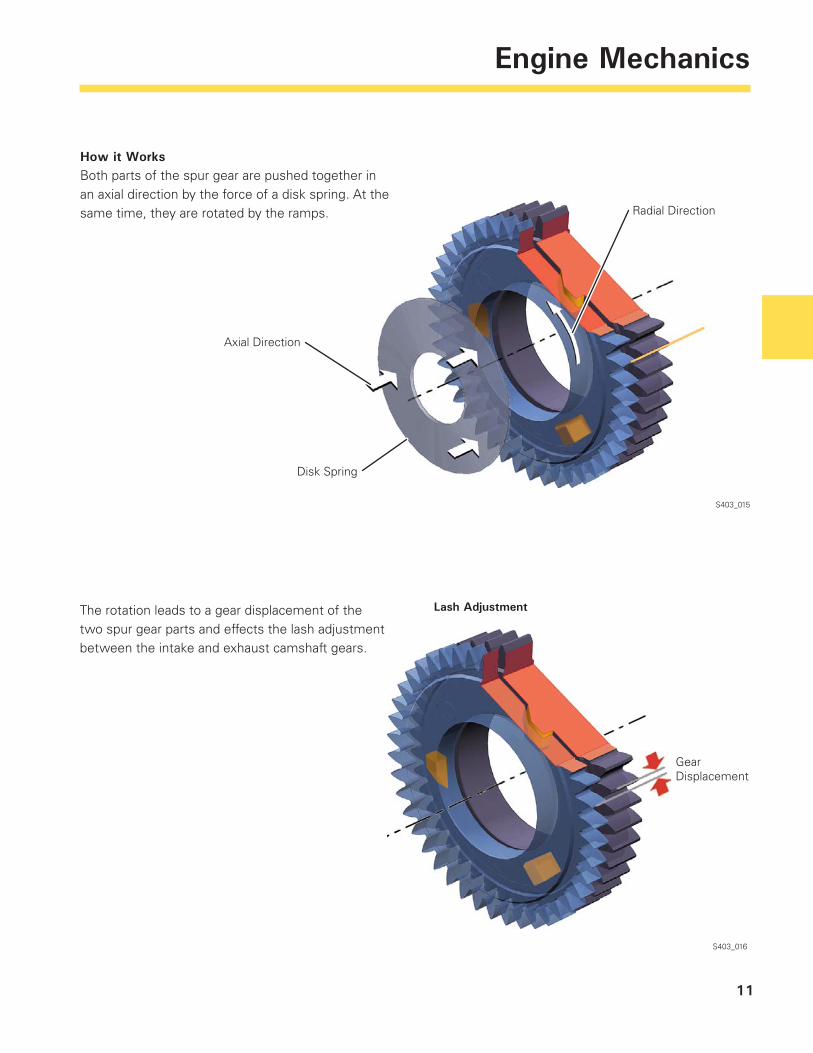
How it WorksBoth parts of the spur gear are pushed together in an axial direction by the force of a disk spring. At the same time, they are rotated by the ramps.
Disk Spring
S403_015
Gear Displacement
S403_016
The rotation leads to a gear displacement of the two spur gear parts and effects the lash adjustment between the intake and exhaust camshaft gears.
Lash Adjustment
Axial Direction
Radial Direction
12
Engine Mechanics
Cylinder Head Gasket
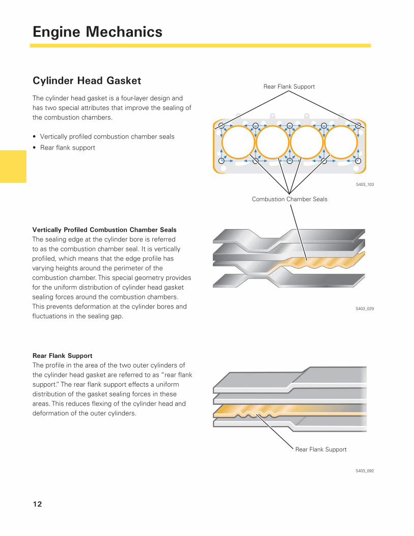
The cylinder head gasket is a four-layer design and has two special attributes that improve the sealing of the combustion chambers.
Vertically profi led combustion chamber seals
Rear fl ank support
•
•
S403_103
S403_029
S403_092
Vertically Profiled Combustion Chamber SealsThe sealing edge at the cylinder bore is referred to as the combustion chamber seal. It is vertically profi led, which means that the edge profi le has varying heights around the perimeter of the combustion chamber. This special geometry provides for the uniform distribution of cylinder head gasket sealing forces around the combustion chambers. This prevents deformation at the cylinder bores and fl uctuations in the sealing gap.
Rear Flank SupportThe profi le in the area of the two outer cylinders of the cylinder head gasket are referred to as “rear fl ank support.” The rear fl ank support effects a uniform distribution of the gasket sealing forces in these areas. This reduces fl exing of the cylinder head and deformation of the outer cylinders.
Rear Flank Support
Combustion Chamber Seals
Rear Flank Support
13
Engine Mechanics
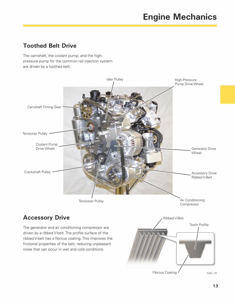
Toothed Belt Drive
The camshaft, the coolant pump, and the high-pressure pump for the common rail injection system are driven by a toothed belt.
S403_116
Accessory Drive
The generator and air conditioning compressor are driven by a ribbed V-belt. The profi le surface of the ribbed V-belt has a fi brous coating. This improves the frictional properties of the belt, reducing unpleasant noise that can occur in wet and cold conditions.
Ribbed V-Belt
Tooth Profi le
Fibrous Coating
Camshaft Timing Gear
Tensioner Pulley
Generator Drive Wheel
Air Conditioning Compressor
Accessory Drive Ribbed V-Belt
Tensioner Pulley
Crankshaft Pulley
Idler Pulley
Coolant Pump Drive Wheel
High-Pressure Pump Drive Wheel
14
Engine Mechanics
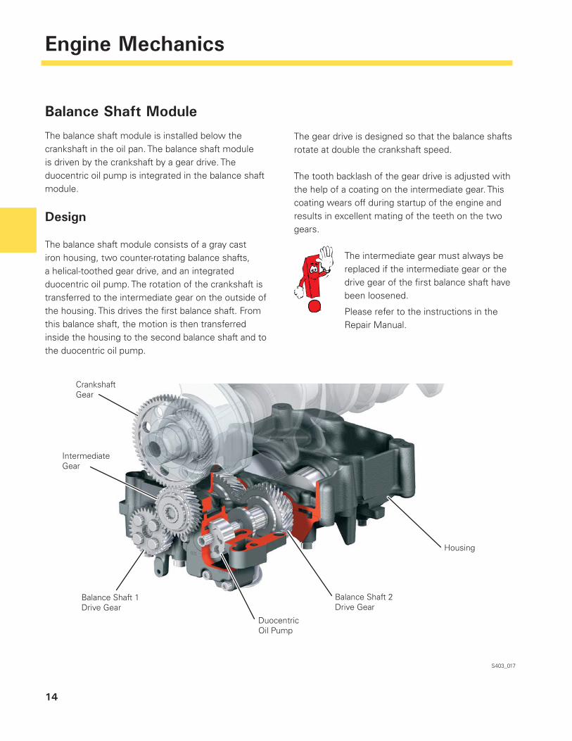
Balance Shaft Module
The balance shaft module is installed below the crankshaft in the oil pan. The balance shaft module is driven by the crankshaft by a gear drive. The duocentric oil pump is integrated in the balance shaft module.
Design
The balance shaft module consists of a gray cast iron housing, two counter-rotating balance shafts, a helical-toothed gear drive, and an integrated duocentric oil pump. The rotation of the crankshaft is transferred to the intermediate gear on the outside of the housing. This drives the fi rst balance shaft. From this balance shaft, the motion is then transferred inside the housing to the second balance shaft and to the duocentric oil pump.
S403_017
The gear drive is designed so that the balance shafts rotate at double the crankshaft speed.
The tooth backlash of the gear drive is adjusted with the help of a coating on the intermediate gear. This coating wears off during startup of the engine and results in excellent mating of the teeth on the two gears.
The intermediate gear must always be replaced if the intermediate gear or the drive gear of the fi rst balance shaft have been loosened.
Please refer to the instructions in the Repair Manual.
Housing
Crankshaft Gear
Intermediate Gear
Balance Shaft 1 Drive Gear
Duocentric Oil Pump
Balance Shaft 2 Drive Gear

15
Notes
16
Engine Mechanics
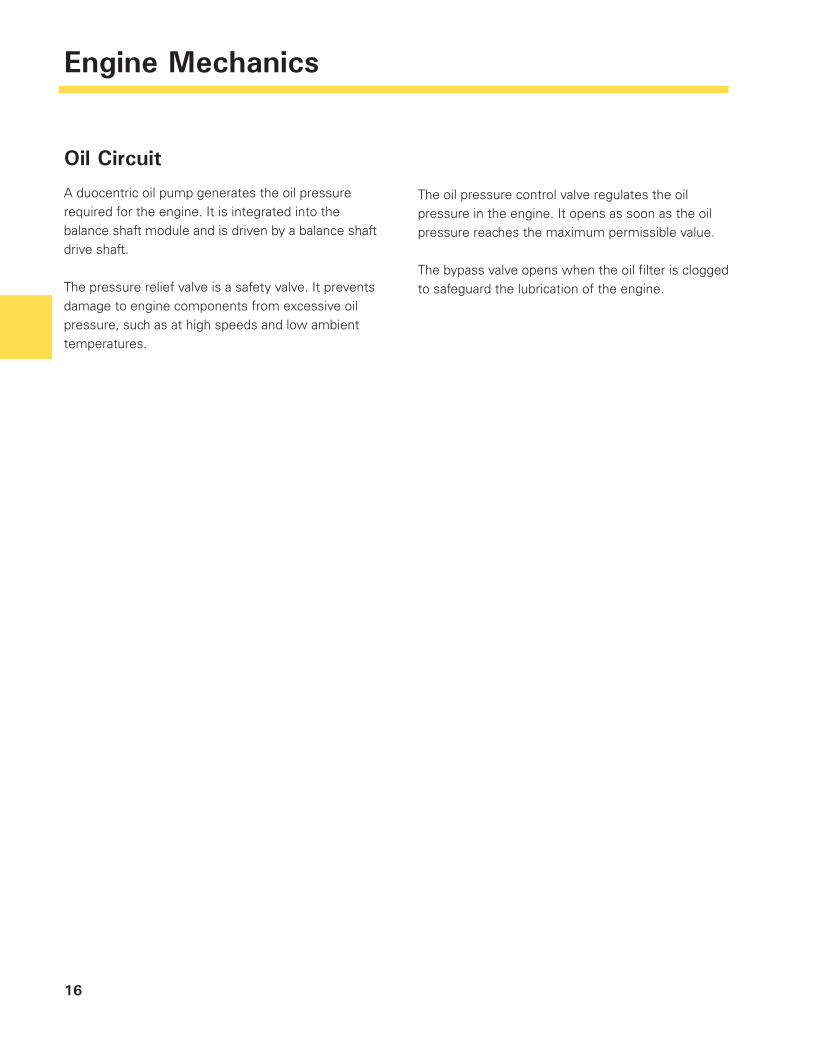
Oil Circuit
A duocentric oil pump generates the oil pressure required for the engine. It is integrated into the balance shaft module and is driven by a balance shaft drive shaft.
The pressure relief valve is a safety valve. It prevents damage to engine components from excessive oil pressure, such as at high speeds and low ambient temperatures.
The oil pressure control valve regulates the oil pressure in the engine. It opens as soon as the oil pressure reaches the maximum permissible value.
The bypass valve opens when the oil fi lter is clogged to safeguard the lubrication of the engine.
17
Engine Mechanics
S403_106
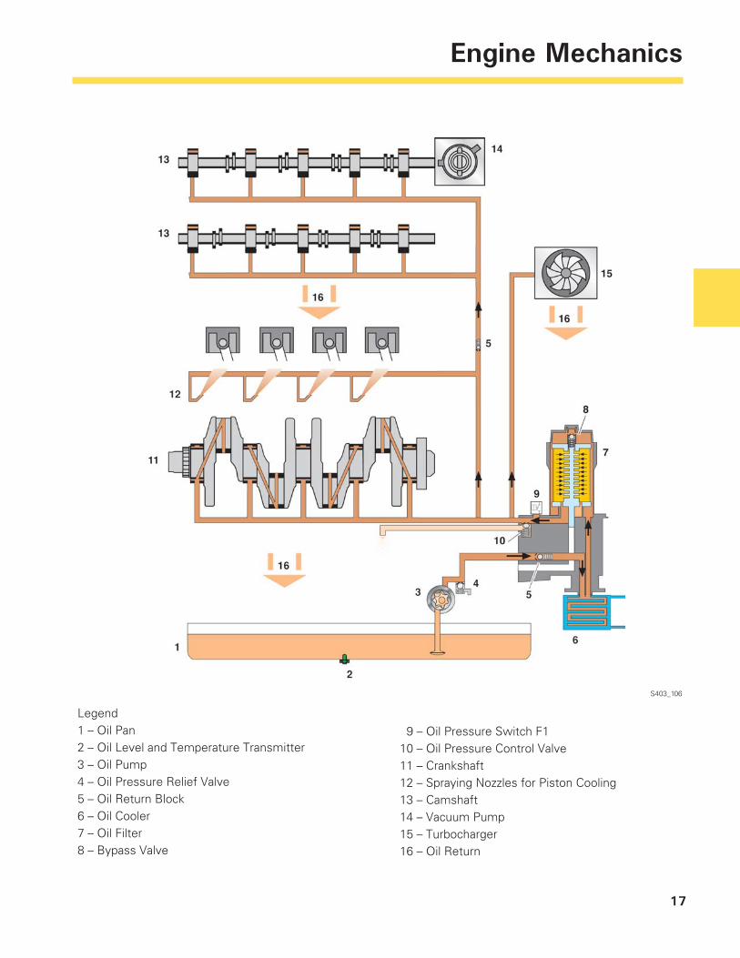
Legend1 – Oil Pan2 – Oil Level and Temperature Transmitter3 – Oil Pump4 – Oil Pressure Relief Valve5 – Oil Return Block6 – Oil Cooler7 – Oil Filter8 – Bypass Valve
9 – Oil Pressure Switch F110 – Oil Pressure Control Valve11 – Crankshaft12 – Spraying Nozzles for Piston Cooling13 – Camshaft14 – Vacuum Pump15 – Turbocharger16 – Oil Return
18
Engine Mechanics
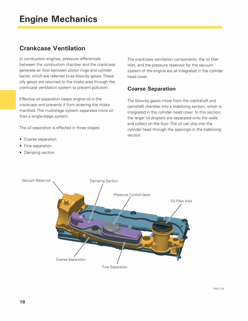
Crankcase Ventilation
In combustion engines, pressure differentials between the combustion chamber and the crankcase generate air fl ow between piston rings and cylinder barrel, which are referred to as blow-by gases. These oily gases are returned to the intake area through the crankcase ventilation system to prevent pollution.
Effective oil separation keeps engine oil in the crankcase and prevents it from entering the intake manifold. This multistage system separates more oil than a single-stage system.
The oil separation is effected in three stages:
Coarse separation
Fine separation
Damping section
•
•
•
S403_019
The crankcase ventilation components, the oil fi ller inlet, and the pressure reservoir for the vacuum system of the engine are all integrated in the cylinder head cover.
Coarse Separation
The blow-by gases move from the crankshaft and camshaft chamber into a stabilizing section, which is integrated in the cylinder head cover. In this section, the larger oil droplets are separated onto the walls and collect on the fl oor. The oil can drip into the cylinder head through the openings in the stabilizing section.
Vacuum Reservoir Damping Section
Oil Filler Inlet
Fine Separation
Coarse Separation
Pressure Control Valve
19
Engine Mechanics
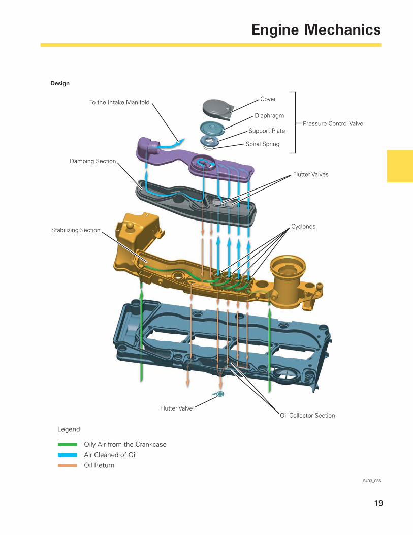
S403_086
To the Intake Manifold
Damping Section
Stabilizing Section
Cover
Diaphragm
Support Plate
Spiral Spring
Flutter Valves
Flutter Valve
Cyclones
Oil Collector Section
Design
Legend
Oily Air from the Crankcase
Air Cleaned of Oil
Oil Return
Pressure Control Valve
20
Engine Mechanics
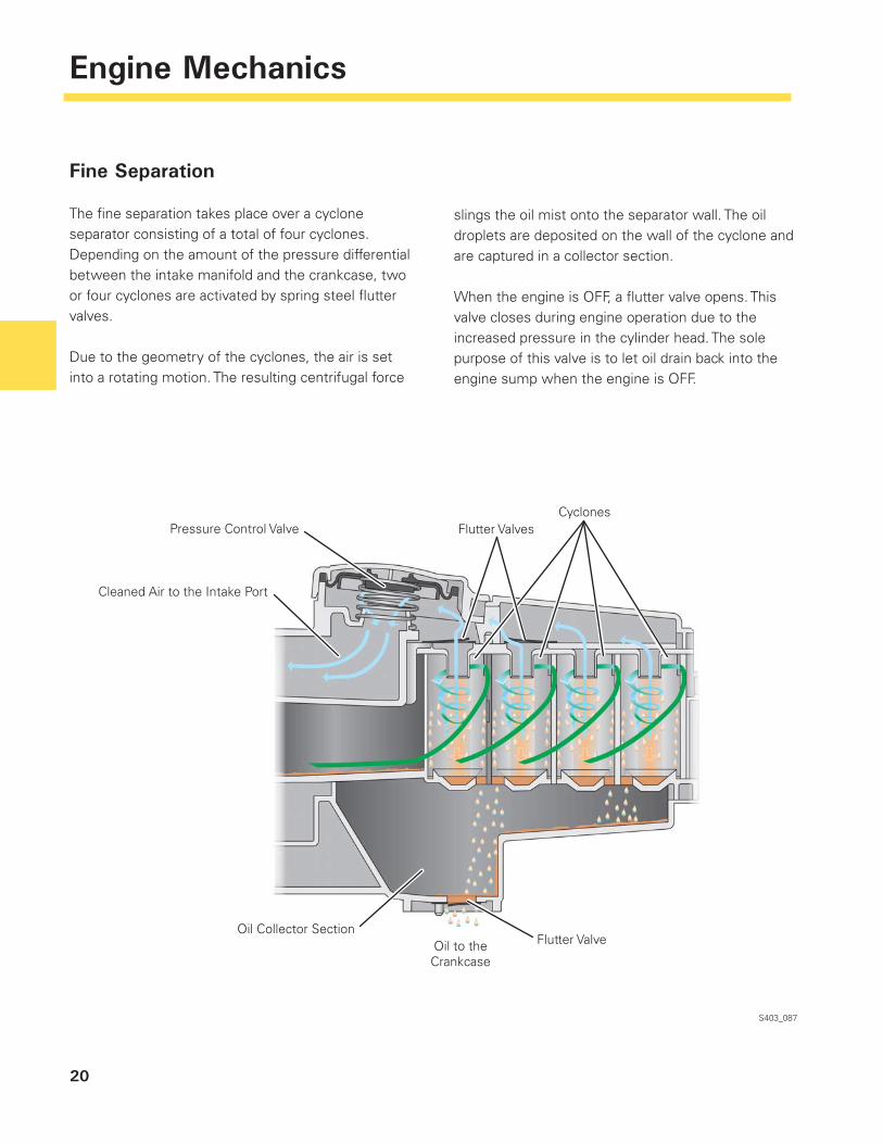
Fine Separation
The fi ne separation takes place over a cyclone separator consisting of a total of four cyclones. Depending on the amount of the pressure differential between the intake manifold and the crankcase, two or four cyclones are activated by spring steel fl utter valves.
Due to the geometry of the cyclones, the air is set into a rotating motion. The resulting centrifugal force
S403_087
slings the oil mist onto the separator wall. The oil droplets are deposited on the wall of the cyclone and are captured in a collector section.
When the engine is OFF, a fl utter valve opens. This valve closes during engine operation due to the increased pressure in the cylinder head. The sole purpose of this valve is to let oil drain back into the engine sump when the engine is OFF.
Cleaned Air to the Intake Port
Pressure Control Valve Flutter ValvesCyclones
Flutter ValveOil to theCrankcase
Oil Collector Section
21
Engine Mechanics
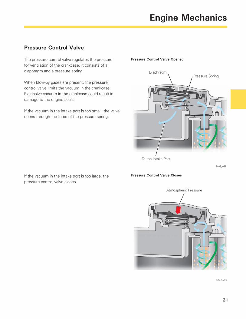
Pressure Control Valve
The pressure control valve regulates the pressure for ventilation of the crankcase. It consists of a diaphragm and a pressure spring.
When blow-by gases are present, the pressure control valve limits the vacuum in the crankcase. Excessive vacuum in the crankcase could result in damage to the engine seals.
If the vacuum in the intake port is too small, the valve opens through the force of the pressure spring.
S403_088
S403_089
If the vacuum in the intake port is too large, the pressure control valve closes.
Pressure Control Valve Opened
Pressure Control Valve Closes
Atmospheric Pressure
DiaphragmPressure Spring
To the Intake Port
22
Engine Mechanics
Damping Section
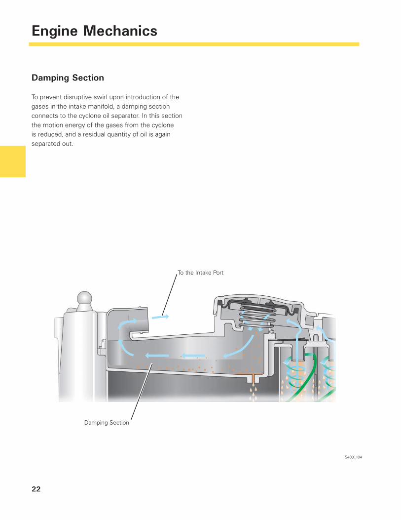
To prevent disruptive swirl upon introduction of the gases in the intake manifold, a damping section connects to the cyclone oil separator. In this section the motion energy of the gases from the cyclone is reduced, and a residual quantity of oil is again separated out.
S403_104
To the Intake Port
Damping Section
1
2
3
4
6 7
8
9
23
Engine Mechanics
Coolant Circuit
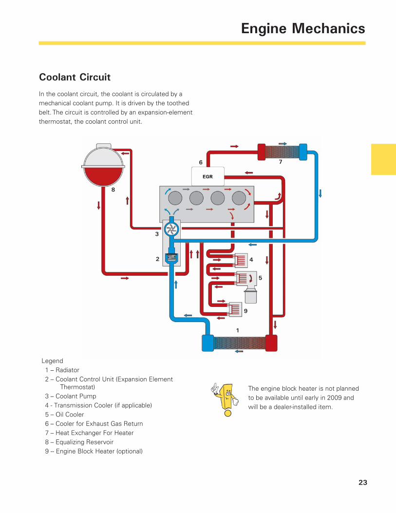
In the coolant circuit, the coolant is circulated by a mechanical coolant pump. It is driven by the toothed belt. The circuit is controlled by an expansion-element thermostat, the coolant control unit.
Legend 1 – Radiator 2 – Coolant Control Unit (Expansion Element
Thermostat) 3 – Coolant Pump 4 - Transmission Cooler (if applicable) 5 – Oil Cooler 6 – Cooler for Exhaust Gas Return 7 – Heat Exchanger For Heater 8 – Equalizing Reservoir 9 -- Engine Block Heater (optional)
5
The engine block heater is not planned to be available until early in 2009 and will be a dealer-installed item.
24
Engine Mechanics
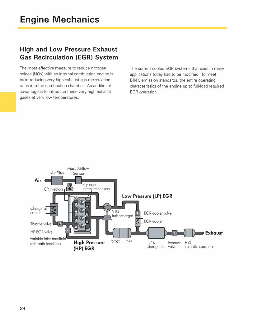
High and Low Pressure Exhaust Gas Recirculation (EGR) System
The most effective measure to reduce nitrogen oxides (NOx) with an internal combustion engine is by introducing very high exhaust gas recirculation rates into the combustion chamber. An additional advantage is to introduce these very high exhaust gases at very low temperatures.
The current cooled EGR systems that exist in many applications today had to be modifi ed. To meet BIN 5 emission standards, the entire operating characteristics of the engine up to full-load required EGR operation.
Air Filter
CR injectors
Throttle valve
HP EGR valve
Variable inlet manifold with path feedback
Charge aircooler
Cylinderpressure sensors
VTGturbocharger
DOC + DPF
EGR cooler
EGR cooler valve
Exhaust
Low Pressure (LP) EGR
High Pressure (HP) EGR
Air
NOxstorage cat.
H2Scatalytic converter
Exhaustvalve
Mass Airflow Sensor
25
Engine Mechanics
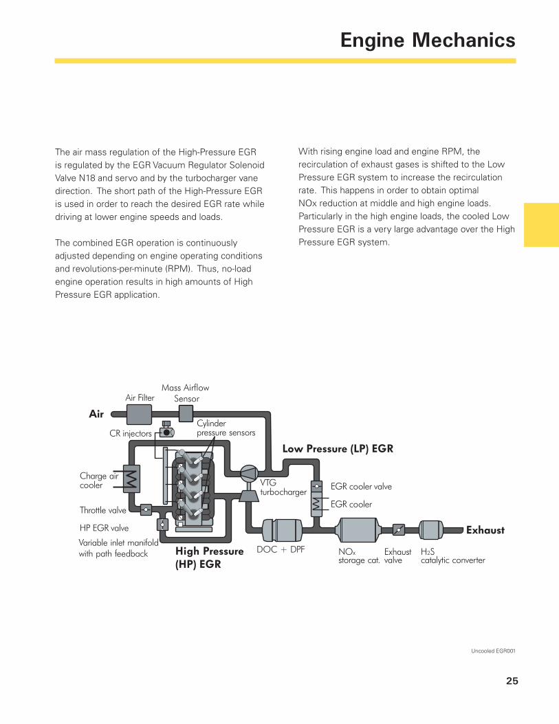
The air mass regulation of the High-Pressure EGR is regulated by the EGR Vacuum Regulator Solenoid Valve N18 and servo and by the turbocharger vane direction. The short path of the High-Pressure EGR is used in order to reach the desired EGR rate while driving at lower engine speeds and loads.
The combined EGR operation is continuously adjusted depending on engine operating conditions and revolutions-per-minute (RPM). Thus, no-load engine operation results in high amounts of High Pressure EGR application.
Uncooled EGR001
With rising engine load and engine RPM, the recirculation of exhaust gases is shifted to the Low Pressure EGR system to increase the recirculation rate. This happens in order to obtain optimal NOx reduction at middle and high engine loads. Particularly in the high engine loads, the cooled Low Pressure EGR is a very large advantage over the High Pressure EGR system.
Air Filter
CR injectors
Throttle valve
HP EGR valve
Variable inlet manifold with path feedback
Charge aircooler
Cylinderpressure sensors
VTGturbocharger
DOC + DPF
EGR cooler
EGR cooler valve
Exhaust
Low Pressure (LP) EGR
High Pressure (HP) EGR
Air
NOxstorage cat.
H2Scatalytic converter
Exhaustvalve
Mass Airflow Sensor
26
Engine Mechanics
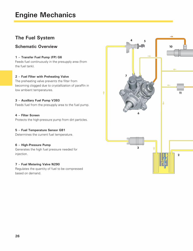
The Fuel System
Schematic Overview
1 – Transfer Fuel Pump (FP) G6Feeds fuel continuously in the presupply area (from the fuel tank).
2 – Fuel Filter with Preheating ValveThe preheating valve prevents the fi lter from becoming clogged due to crystallization of paraffi n in low ambient temperatures.
3 – Auxiliary Fuel Pump V393Feeds fuel from the presupply area to the fuel pump.
4 – Filter ScreenProtects the high-pressure pump from dirt particles.
5 – Fuel Temperature Sensor G81Determines the current fuel temperature.
6 – High-Pressure PumpGenerates the high fuel pressure needed for injection.
7 – Fuel Metering Valve N290Regulates the quantity of fuel to be compressed based on demand.
27
Engine Mechanics
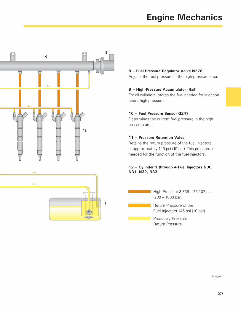
8 – Fuel Pressure Regulator Valve N276Adjusts the fuel pressure in the high-pressure area.
9 – High-Pressure Accumulator (Rail)For all cylinders, stores the fuel needed for injection under high pressure.
10 – Fuel Pressure Sensor G247Determines the current fuel pressure in the high-pressure area.
11 – Pressure Retention ValveRetains the return pressure of the fuel injectors at approximately 145 psi (10 bar). This pressure is needed for the function of the fuel injectors.
12 – Cylinder 1 through 4 Fuel Injectors N30, N31, N32, N33
S403_021
High Pressure 3,336 – 26,107 psi (230 – 1800 bar)
Return Pressure of theFuel Injectors 145 psi (10 bar)
Presupply PressureReturn Pressure
28
Engine Mechanics
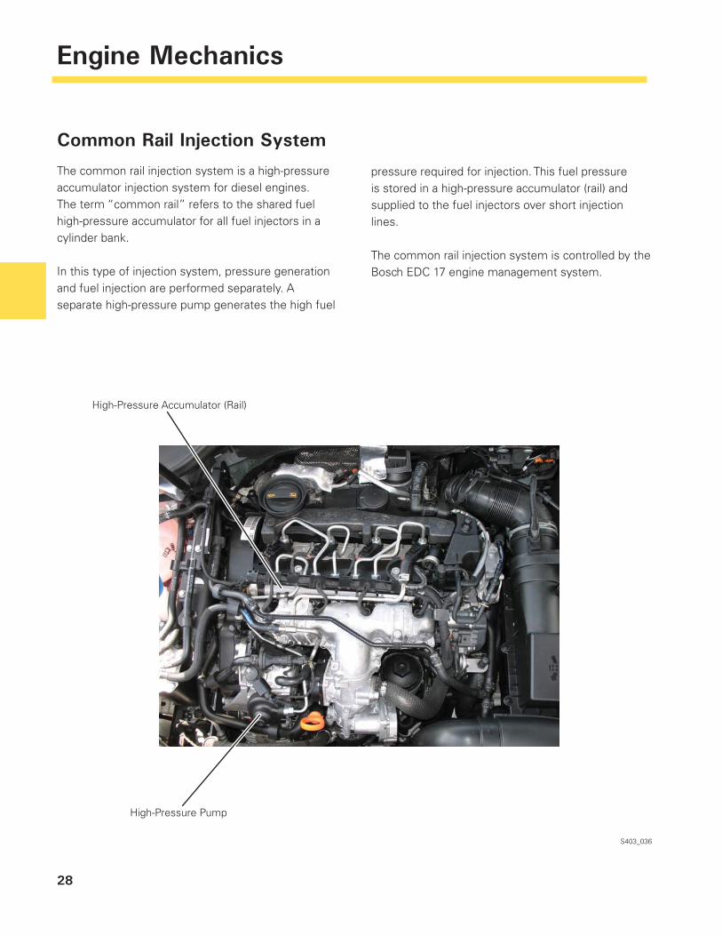
Common Rail Injection System
The common rail injection system is a high-pressure accumulator injection system for diesel engines. The term “common rail” refers to the shared fuel high-pressure accumulator for all fuel injectors in a cylinder bank.
In this type of injection system, pressure generation and fuel injection are performed separately. A separate high-pressure pump generates the high fuel
S403_036
High-Pressure Accumulator (Rail)
High-Pressure Pump
pressure required for injection. This fuel pressure is stored in a high-pressure accumulator (rail) and supplied to the fuel injectors over short injection lines.
The common rail injection system is controlled by the Bosch EDC 17 engine management system.
29
Engine Mechanics
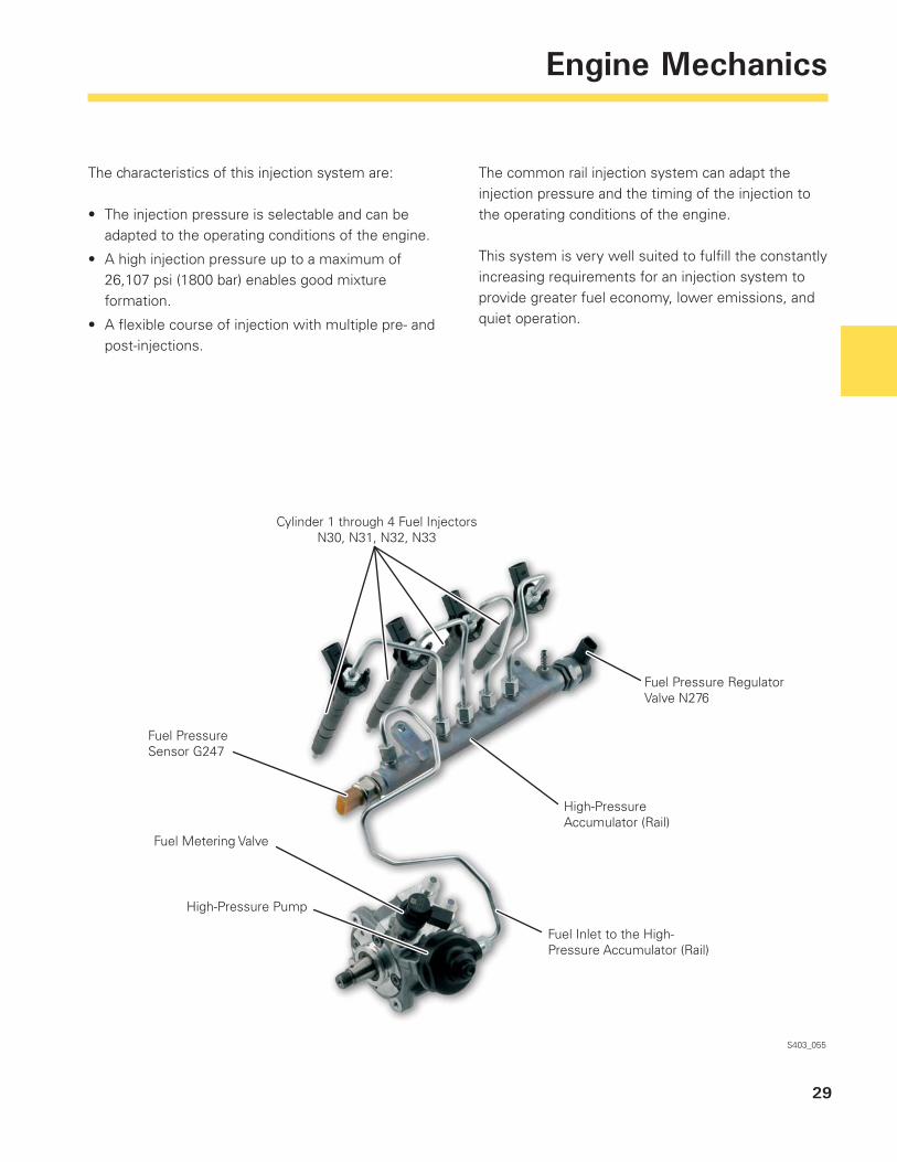
The characteristics of this injection system are:
The injection pressure is selectable and can be adapted to the operating conditions of the engine.
A high injection pressure up to a maximum of 26,107 psi (1800 bar) enables good mixture formation.
A fl exible course of injection with multiple pre- and post-injections.
•
•
•
S403_055
Cylinder 1 through 4 Fuel InjectorsN30, N31, N32, N33
Fuel Pressure Sensor G247
Fuel Metering Valve
High-Pressure Pump
Fuel Pressure Regulator Valve N276
High-Pressure Accumulator (Rail)
Fuel Inlet to the High-Pressure Accumulator (Rail)
The common rail injection system can adapt the injection pressure and the timing of the injection to the operating conditions of the engine.
This system is very well suited to fulfi ll the constantly increasing requirements for an injection system to provide greater fuel economy, lower emissions, and quiet operation.
30
Engine Mechanics
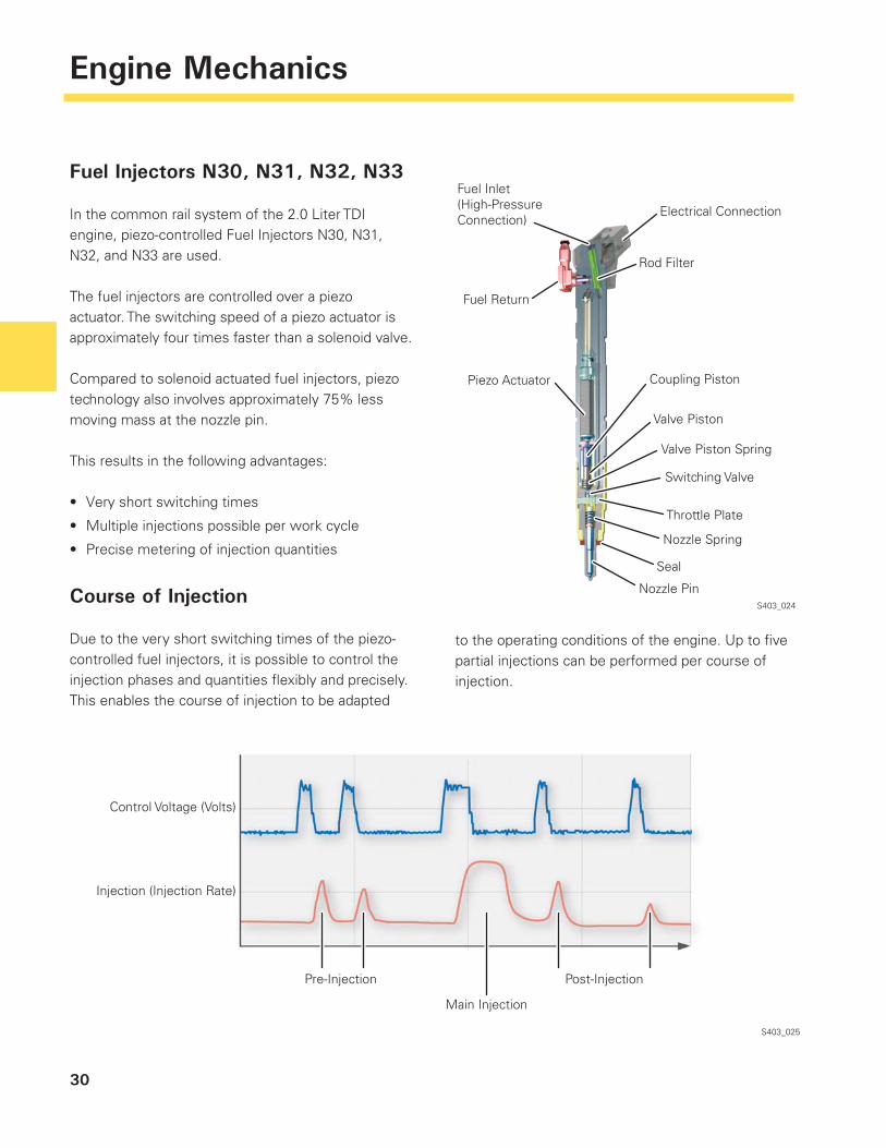
Fuel Injectors N30, N31, N32, N33
In the common rail system of the 2.0 Liter TDI engine, piezo-controlled Fuel Injectors N30, N31, N32, and N33 are used.
The fuel injectors are controlled over a piezo actuator. The switching speed of a piezo actuator is approximately four times faster than a solenoid valve.
Compared to solenoid actuated fuel injectors, piezo technology also involves approximately 75% less moving mass at the nozzle pin.
This results in the following advantages:
Very short switching times
Multiple injections possible per work cycle
Precise metering of injection quantities
Course of Injection
Due to the very short switching times of the piezo-controlled fuel injectors, it is possible to control the injection phases and quantities fl exibly and precisely. This enables the course of injection to be adapted
•
•
•
S403_024
S403_025
to the operating conditions of the engine. Up to fi ve partial injections can be performed per course of injection.
Fuel Inlet(High-PressureConnection)
Fuel Return
Electrical Connection
Rod Filter
Piezo Actuator
Control Voltage (Volts)
Injection (Injection Rate)
Main Injection
Post-Injection
Coupling Piston
Valve Piston
Valve Piston Spring
Switching Valve
Throttle Plate
Nozzle Spring
Seal
Nozzle Pin
Pre-Injection
31
Engine Mechanics
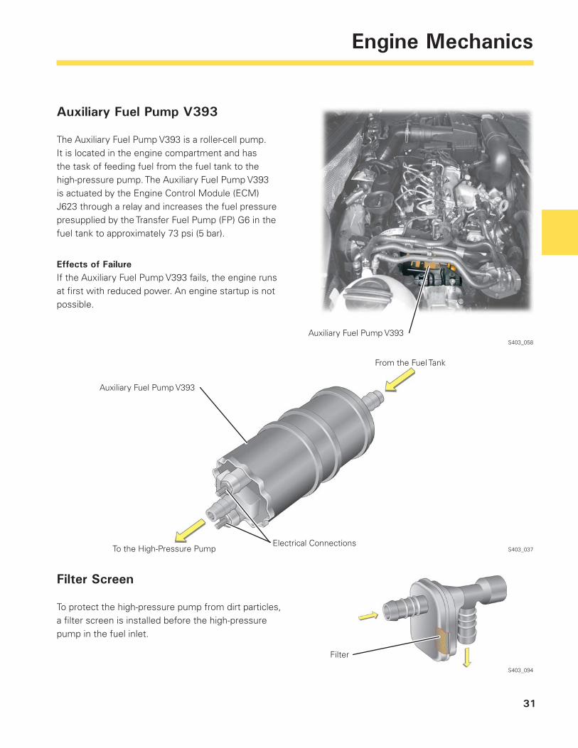
Auxiliary Fuel Pump V393
The Auxiliary Fuel Pump V393 is a roller-cell pump. It is located in the engine compartment and has the task of feeding fuel from the fuel tank to the high-pressure pump. The Auxiliary Fuel Pump V393 is actuated by the Engine Control Module (ECM) J623 through a relay and increases the fuel pressure presupplied by the Transfer Fuel Pump (FP) G6 in the fuel tank to approximately 73 psi (5 bar).
Effects of FailureIf the Auxiliary Fuel Pump V393 fails, the engine runs at fi rst with reduced power. An engine startup is not possible.
S403_058
S403_037
S403_094
Filter
Auxiliary Fuel Pump V393
Auxiliary Fuel Pump V393
To the High-Pressure Pump
From the Fuel Tank
Electrical Connections
Filter Screen
To protect the high-pressure pump from dirt particles, a fi lter screen is installed before the high-pressure pump in the fuel inlet.
32
Engine Mechanics
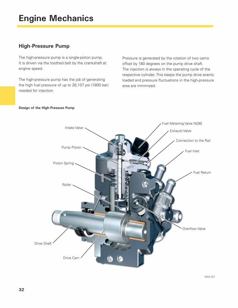
High-Pressure Pump
The high-pressure pump is a single-piston pump. It is driven via the toothed belt by the crankshaft at engine speed.
The high-pressure pump has the job of generating the high fuel pressure of up to 26,107 psi (1800 bar) needed for injection.
S403_027
Design of the High-Pressure Pump
Pressure is generated by the rotation of two cams offset by 180 degrees on the pump drive shaft. The injection is always in the operating cycle of the respective cylinder. This keeps the pump drive evenly loaded and pressure fl uctuations in the high-pressure area are minimized.
Fuel Metering Valve N290
Exhaust Valve
Connection to the Rail
Fuel Inlet
Fuel Return
Overfl ow Valve
Intake Valve
Pump Piston
Piston Spring
Roller
Drive Shaft
Drive Cam
33
Engine Mechanics
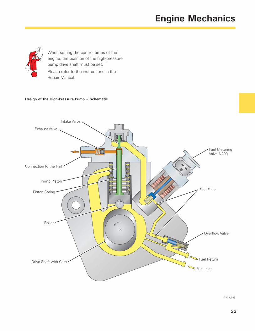
When setting the control times of the engine, the position of the high-pressure pump drive shaft must be set.
Please refer to the instructions in the Repair Manual.
Design of the High-Pressure Pump – Schematic
S403_049
Intake Valve
Exhaust Valve
Connection to the Rail
Pump Piston
Piston Spring
Roller
Drive Shaft with Cam
Fuel Metering Valve N290
Fine Filter
Overfl ow Valve
Fuel Return
Fuel Inlet
34
Engine Mechanics
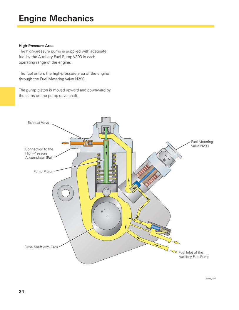
High-Pressure AreaThe high-pressure pump is supplied with adequate fuel by the Auxiliary Fuel Pump V393 in each operating range of the engine.
The fuel enters the high-pressure area of the engine through the Fuel Metering Valve N290.
The pump piston is moved upward and downward by the cams on the pump drive shaft.
S403_107
Exhaust Valve
Connection to the High-Pressure Accumulator (Rail)
Pump Piston
Drive Shaft with Cam
Fuel Metering Valve N290
Fuel Inlet of the Auxiliary Fuel Pump
35
Engine Mechanics
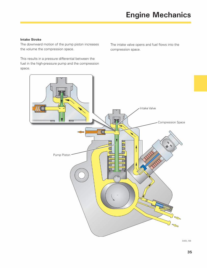
Intake StrokeThe downward motion of the pump piston increases the volume the compression space.
This results in a pressure differential between the fuel in the high-pressure pump and the compression space.
S403_108
The intake valve opens and fuel fl ows into the compression space.
Intake Valve
Compression Space
Pump Piston
36
Engine Mechanics
Delivery StrokeWith the beginning of the upward motion of the pump piston, the pressure in the compression space increases and the intake valve closes.
S403_109
As soon as the fuel pressure in the compression space exceeds the pressure in the high-pressure area, the exhaust valve (check valve) opens and fuel enters the high-pressure accumulator (rail).
Exhaust Valve
Connection to the High-Pressure Accumulator (Rail)
Pump Piston
37
Engine Mechanics
Fuel Metering Valve N290
Fuel Metering Valve N290 is integrated in the high-pressure pump. It ensures demand-based control of the fuel pressure in the high-pressure area. The Fuel Metering Valve N290 controls the fuel quantity that is needed for high-pressure generation. This represents an advantage, in that the high-pressure pump must generate only the pressure needed for the momentary operating situation. The power consumption of the high-pressure pump is reduced and unnecessary warming up of the fuel is avoided.
FunctionThe non-energized state the Fuel Metering Valve N290 is open. To reduce the feed quantity to the
S403_110
compression space, the valve is actuated by the Engine Control Module (ECM) J623 with a pulse-width modulated (PWM) signal.
Through the PWM signal the Fuel Metering Valve N290 is closed cyclically. Depending on the duty cycle, the position of the locking piston changes as does the amount of fuel into the compression space of the high-pressure pump.
Effects of FailureEngine power is reduced. Engine management operates in emergency mode.
To the Compression Space
Feed from Pump Interior
38
Engine Mechanics
Low-Pressure Area
Overflow ValveThe fuel pressure in the low-pressure area of the high-pressure pump is controlled by the overfl ow valve.
FunctionThe Auxiliary Fuel Pump V393 delivers fuel from the fuel tank with a pressure of approximately 73 psi (5 bar) into the high-pressure pump. Thus the fuel supply to the high-pressure pump is ensured in all operating conditions.
The overfl ow valve regulates the fuel pressure in the high-pressure pump to approximately 62 psi (4.3 bar).
The fuel delivered by the Auxiliary Fuel Pump V393 acts in opposition to the piston and the piston spring of the overfl ow valve. With a fuel pressure over 62 psi (4.3 bar), the overfl ow valve opens and clears the way to the fuel return. The excess fuel fl ows through the fuel return into the fuel tank.
S403_111
Overfl ow Valve
Fuel Return
Fuel Presupply
39
Engine Mechanics
Control of the Fuel High Pressure
In the common rail injection system, the fuel high pressure is controlled by a so-called two-controller concept.
Depending on the operating conditions, the high fuel pressure is regulated either by the Fuel Pressure Regulator Valve N276 or the Fuel Metering Valve N290. The valves are actuated by the Engine Control Module (ECM) J623 with a pulse-width modulated (PWM) signal.
Control by the Fuel Pressure Regulator Valve N276At engine start and for preheating of the fuel, the high fuel pressure is controlled by the Fuel Pressure Regulator Valve N276. To heat up the fuel quickly, the high-pressure pump delivers and compresses more fuel than is needed. The excess fuel is discharged by the Fuel Pressure Regulator Valve N276 into the fuel return.
Two-Controller Concept
Control by the Fuel Metering Valve N290With large injection quantities and high rail pressures, the high fuel pressure is controlled by the Fuel Metering Valve N290. This effects a demand-based regulation of the fuel high pressure. The power consumption of the high-pressure pump is reduced and unnecessary heating up of the fuel is avoided.
Control by Both ValvesIn idling, in trailing throttle condition, and with small injection quantities, the fuel pressure is controlled by both valves simultaneously. This enables precise control, which improves idling quality and the transition into trailing throttle condition.
S403_030
Control of Fuel High Pressure by Fuel Pressure Regulator Valve N276
Control of Fuel High Pressure by Fuel Metering Valve N290
Control by Both Valves
Engine Speed
Inje
ctio
n Q
uant
ity
40
Engine Mechanics
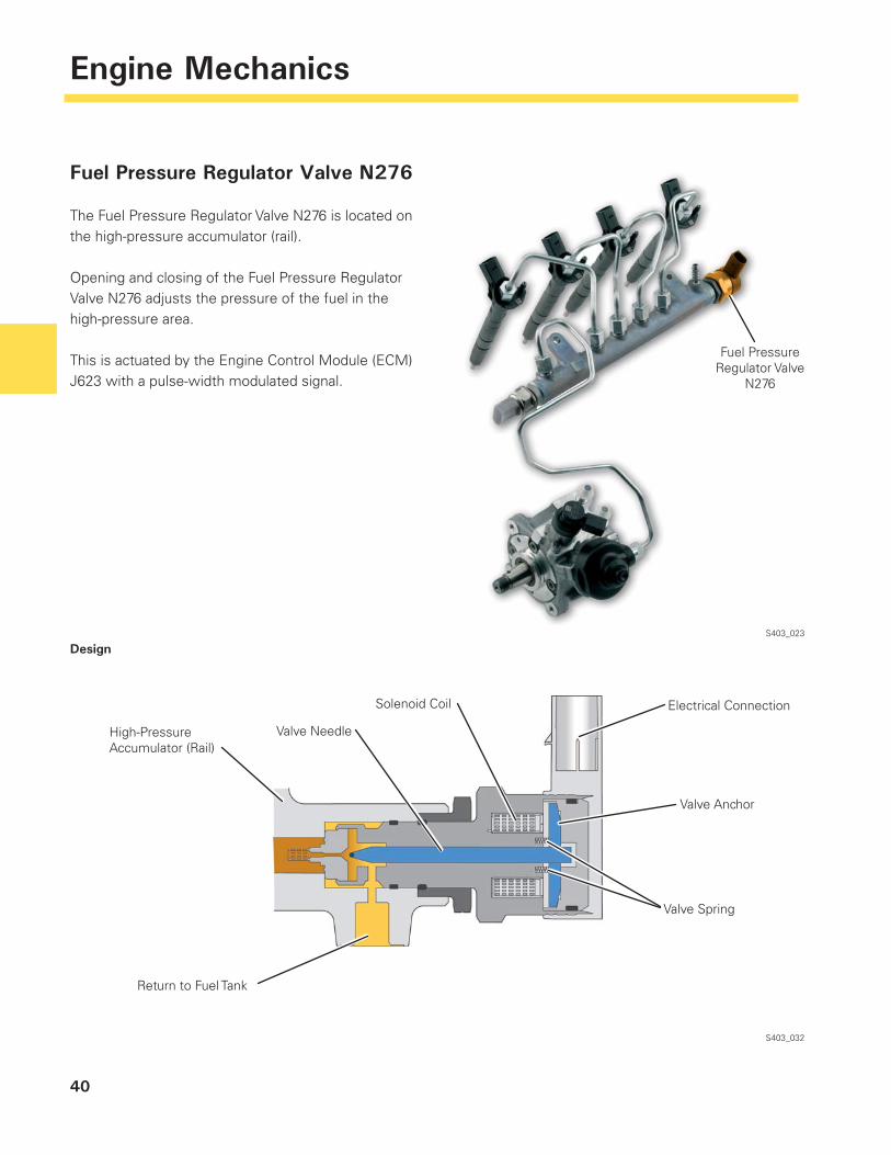
Fuel Pressure Regulator Valve N276
The Fuel Pressure Regulator Valve N276 is located on the high-pressure accumulator (rail).
Opening and closing of the Fuel Pressure Regulator Valve N276 adjusts the pressure of the fuel in the high-pressure area.
This is actuated by the Engine Control Module (ECM) J623 with a pulse-width modulated signal.
S403_023
Design
S403_032
Fuel Pressure Regulator Valve
N276
High-Pressure Accumulator (Rail)
Valve Needle
Solenoid Coil Electrical Connection
Valve Anchor
Valve Spring
Return to Fuel Tank
41
Engine Mechanics
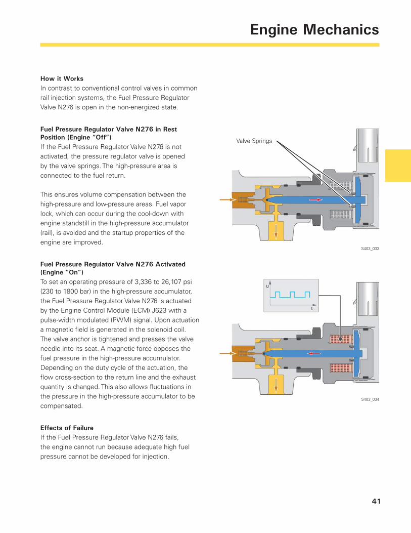
How it WorksIn contrast to conventional control valves in common rail injection systems, the Fuel Pressure Regulator Valve N276 is open in the non-energized state.
Fuel Pressure Regulator Valve N276 in Rest Position (Engine “Off”)If the Fuel Pressure Regulator Valve N276 is not activated, the pressure regulator valve is opened by the valve springs. The high-pressure area is connected to the fuel return.
This ensures volume compensation between the high-pressure and low-pressure areas. Fuel vapor lock, which can occur during the cool-down with engine standstill in the high-pressure accumulator (rail), is avoided and the startup properties of the engine are improved.
Fuel Pressure Regulator Valve N276 Activated (Engine “On”)To set an operating pressure of 3,336 to 26,107 psi (230 to 1800 bar) in the high-pressure accumulator, the Fuel Pressure Regulator Valve N276 is actuated by the Engine Control Module (ECM) J623 with a pulse-width modulated (PWM) signal. Upon actuation a magnetic fi eld is generated in the solenoid coil. The valve anchor is tightened and presses the valve needle into its seat. A magnetic force opposes the fuel pressure in the high-pressure accumulator. Depending on the duty cycle of the actuation, the fl ow cross-section to the return line and the exhaust quantity is changed. This also allows fl uctuations in the pressure in the high-pressure accumulator to be compensated.
Effects of FailureIf the Fuel Pressure Regulator Valve N276 fails, the engine cannot run because adequate high fuel pressure cannot be developed for injection.
S403_033
Valve Springs
S403_034
42
Engine Management SystemEngine Management System
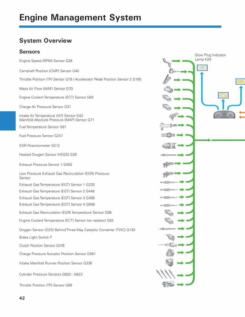
System Overview
Sensors
Throttle Position (TP) Sensor G69
Diesel Particle FilteIndicator Lamp K23
Malfunction Indicator Lamp (MIL) K83
Instrument Cluster Control Module J285
Engine Speed (RPM) Sensor G28
Camshaft Position (CMP) Sensor G40
Throttle Position (TP) Sensor G79 / Accelerator Pedal Position Sensor 2 G185
Mass Air Flow (MAF) Sensor G70
Engine Coolant Temperature (ECT) Sensor G62
Intake Air Temperature (IAT) Sensor G42Manifold Absolute Pressure (MAP) Sensor G71
Fuel Temperature Sensor G81
Fuel Pressure Sensor G247
EGR Potentiometer G212
Heated Oxygen Sensor (HO2S) G39
Exhaust Pressure Sensor 1 G450
Exhaust Gas Temperature (EGT) Sensor 1 G235
Exhaust Gas Temperature (EGT) Sensor 3 G495
Exhaust Gas Temperature (EGT) Sensor 4 G648
Brake Light Switch F
Clutch Position Sensor G476
Charge Pressure Actuator Position Sensor G581
Intake Manifold Runner Position Sensor G336
Charge Air Pressure Sensor G31
Exhaust Gas Recirculation (EGR) Temperature Sensor G98
Cylinder Pressure Sensors G620 - G623
Low Pressure Exhaust Gas Recirculation (EGR) Pressure Sensor
Exhaust Gas Temperature (EGT) Sensor 2 G448
Glow Plug Indicator Lamp K29
Engine Coolant Temperature (ECT) Sensor (on radiator) G83
Oxygen Sensor (O2S) Behind Three Way Catalytic Converter (TWC) G130
43
Engine Management System
er 31
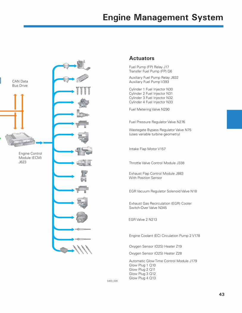
Actuators
S403_028
Automatic Glow Time Control Module J179Glow Plug 1 Q10Glow Plug 2 Q11Glow Plug 3 Q12Glow Plug 4 Q13
CAN Data Bus Drive
Engine Control Module (ECM) J623
Fuel Pump (FP) Relay J17Transfer Fuel Pump (FP) G6
Auxiliary Fuel Pump Relay J832Auxiliary Fuel Pump V393
Cylinder 1 Fuel Injector N30Cylinder 2 Fuel Injector N31Cylinder 3 Fuel Injector N32Cylinder 4 Fuel Injector N33
Fuel Metering Valve N290
Fuel Pressure Regulator Valve N276
Wastegate Bypass Regulator Valve N75(uses variable turbine geometry)
Intake Flap Motor V157
Throttle Valve Control Module J338
EGR Vacuum Regulator Solenoid Valve N18
Exhaust Gas Recirculation (EGR) Cooler Switch-Over Valve N345
Engine Coolant (EC) Circulation Pump 2 V178
Oxygen Sensor (O2S) Heater Z19
Exhaust Flap Control Module J883With Position Sensor
EGR Valve 2 N213
Oxygen Sensor (O2S) Heater Z28
44
Engine Management System
Electronic Diesel Control (EDC) Engine Management
The engine management system of the 2.0 Liter TDI engine with common rail injection system is the electronic diesel control EDC17 from Bosch.
The EDC17 engine management system is the successor of EDC16. EDC17 has greater processing capability and a larger storage capacity than EDC16.
It also offers the option of integrating control functions for future technologies.
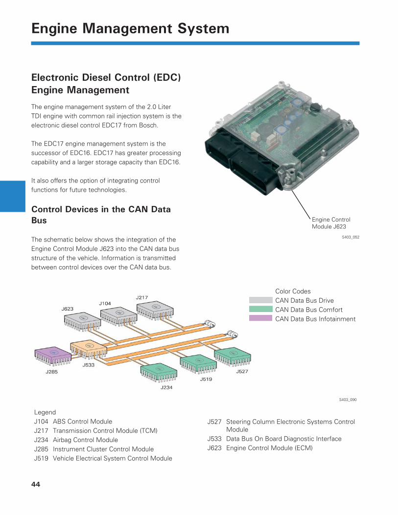
Control Devices in the CAN Data Bus
The schematic below shows the integration of the Engine Control Module J623 into the CAN data bus structure of the vehicle. Information is transmitted between control devices over the CAN data bus.
S403_052
S403_090
Color CodesCAN Data Bus DriveCAN Data Bus ComfortCAN Data Bus Infotainment
LegendJ104 ABS Control Module J217 Transmission Control Module (TCM) J234 Airbag Control Module J285 Instrument Cluster Control Module J519 Vehicle Electrical System Control Module
J527 Steering Column Electronic Systems Control Module
J533 Data Bus On Board Diagnostic InterfaceJ623 Engine Control Module (ECM)
Engine Control Module J623
45
Engine Management System
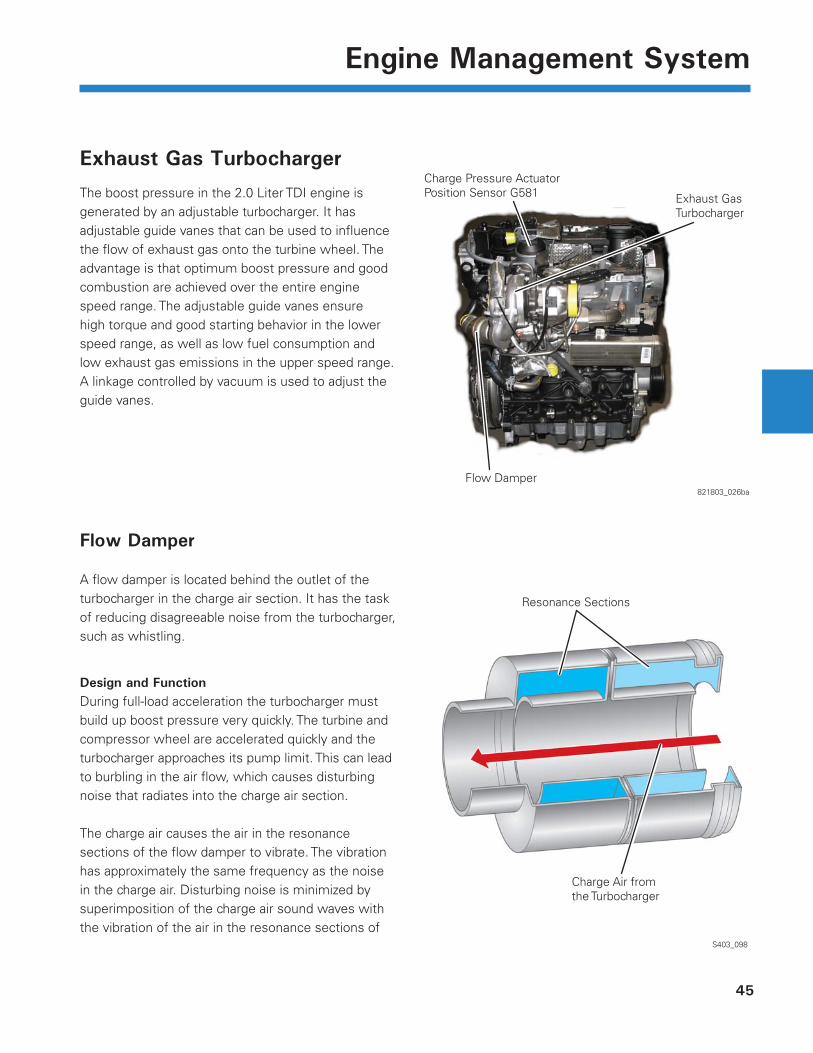
Exhaust Gas Turbocharger
The boost pressure in the 2.0 Liter TDI engine is generated by an adjustable turbocharger. It has adjustable guide vanes that can be used to infl uence the fl ow of exhaust gas onto the turbine wheel. The advantage is that optimum boost pressure and good combustion are achieved over the entire engine speed range. The adjustable guide vanes ensure high torque and good starting behavior in the lower speed range, as well as low fuel consumption and low exhaust gas emissions in the upper speed range. A linkage controlled by vacuum is used to adjust the guide vanes.
821803_026ba
S403_098
Resonance Sections
Charge Air fromthe Turbocharger
Charge Pressure ActuatorPosition Sensor G581 Exhaust Gas
Turbocharger
Flow Damper
Flow Damper
A fl ow damper is located behind the outlet of the turbocharger in the charge air section. It has the task of reducing disagreeable noise from the turbocharger, such as whistling.
Design and FunctionDuring full-load acceleration the turbocharger must build up boost pressure very quickly. The turbine and compressor wheel are accelerated quickly and the turbocharger approaches its pump limit. This can lead to burbling in the air fl ow, which causes disturbing noise that radiates into the charge air section.
The charge air causes the air in the resonance sections of the fl ow damper to vibrate. The vibration has approximately the same frequency as the noise in the charge air. Disturbing noise is minimized by superimposition of the charge air sound waves with the vibration of the air in the resonance sections of
4
5
6
7
8
11
46
Engine Management System
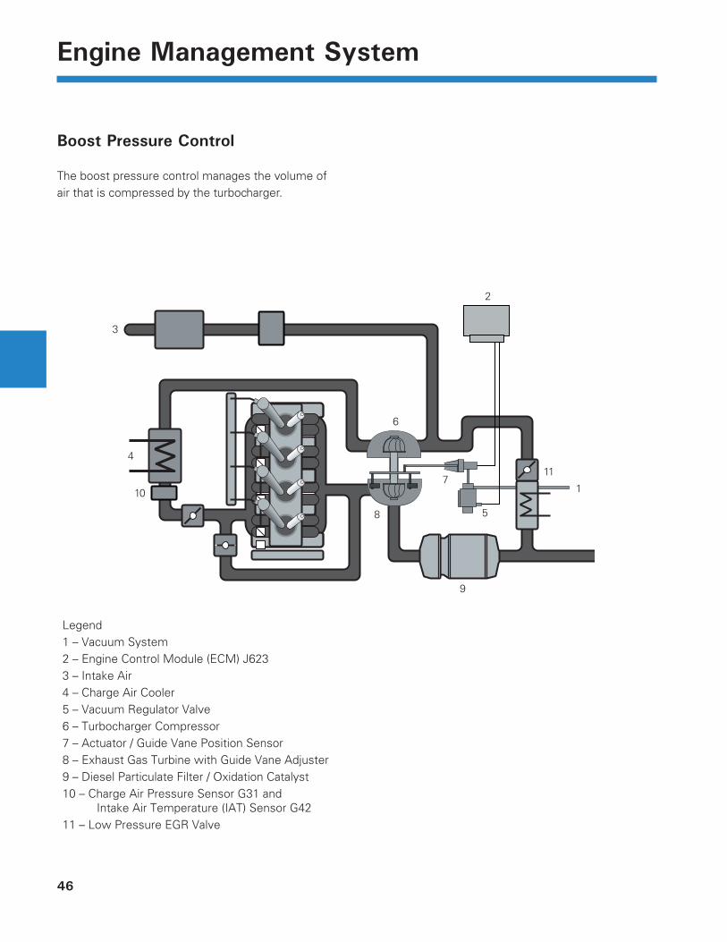
Boost Pressure Control
The boost pressure control manages the volume of air that is compressed by the turbocharger.
Legend1 – Vacuum System2 – Engine Control Module (ECM) J6233 – Intake Air4 – Charge Air Cooler5 – Vacuum Regulator Valve6 – Turbocharger Compressor7 – Actuator / Guide Vane Position Sensor8 – Exhaust Gas Turbine with Guide Vane Adjuster9 – Diesel Particulate Filter / Oxidation Catalyst10 – Charge Air Pressure Sensor G31 and
Intake Air Temperature (IAT) Sensor G4211 – Low Pressure EGR Valve
2
1
3
9
10
47
Engine Management System
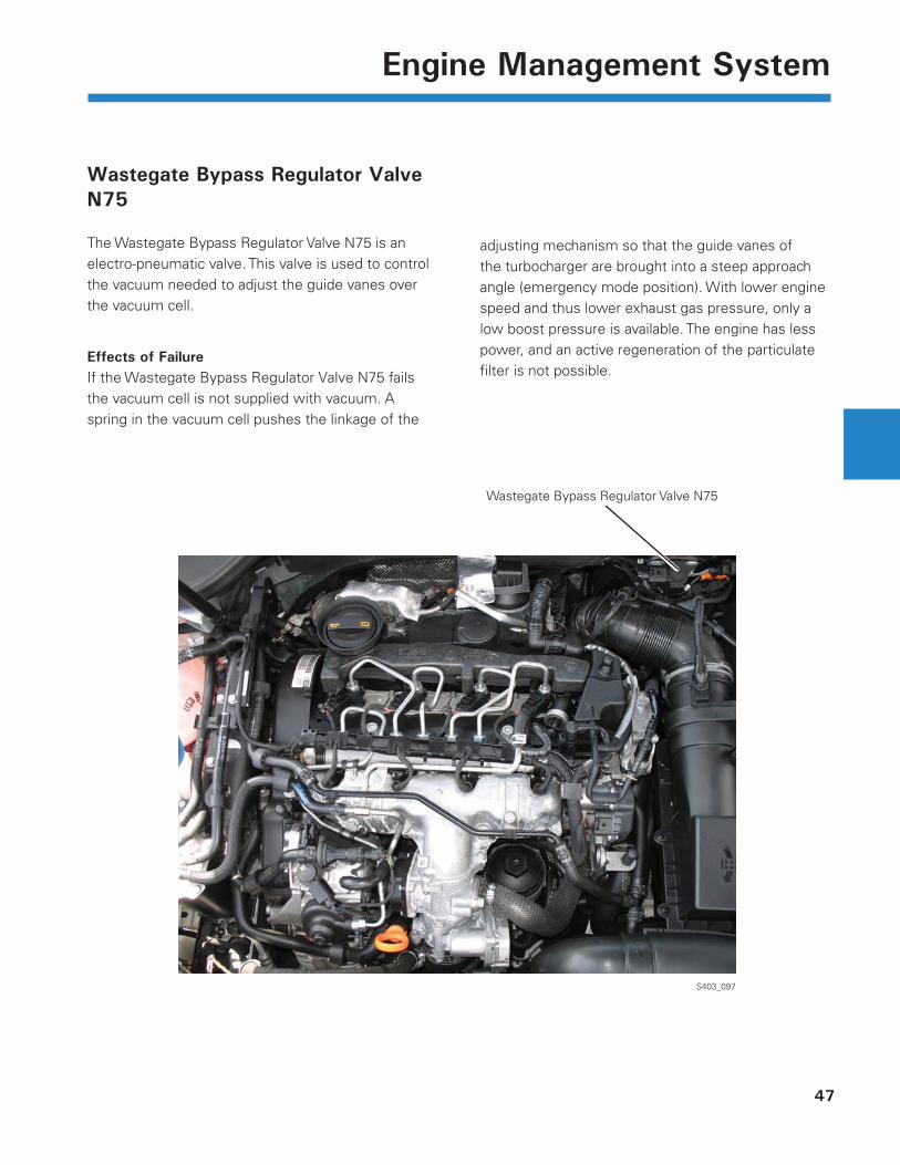
Wastegate Bypass Regulator Valve N75
The Wastegate Bypass Regulator Valve N75 is an electro-pneumatic valve. This valve is used to control the vacuum needed to adjust the guide vanes over the vacuum cell.
Effects of FailureIf the Wastegate Bypass Regulator Valve N75 fails the vacuum cell is not supplied with vacuum. A spring in the vacuum cell pushes the linkage of the
S403_097
Wastegate Bypass Regulator Valve N75
adjusting mechanism so that the guide vanes of the turbocharger are brought into a steep approach angle (emergency mode position). With lower engine speed and thus lower exhaust gas pressure, only a low boost pressure is available. The engine has less power, and an active regeneration of the particulate fi lter is not possible.
48
Engine Management System
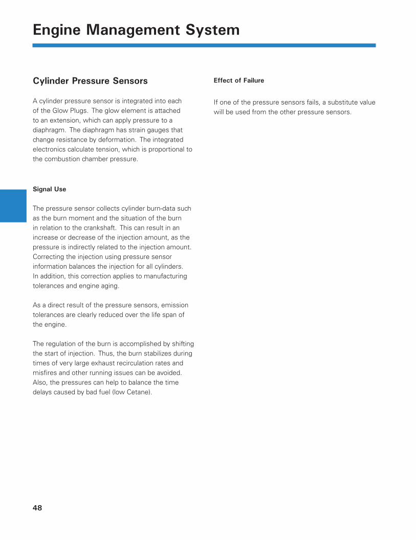
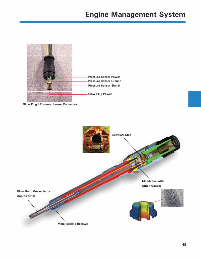
Cylinder Pressure Sensors
A cylinder pressure sensor is integrated into each of the Glow Plugs. The glow element is attached to an extension, which can apply pressure to a diaphragm. The diaphragm has strain gauges that change resistance by deformation. The integrated electronics calculate tension, which is proportional to the combustion chamber pressure.
Signal Use
The pressure sensor collects cylinder burn-data such as the burn moment and the situation of the burn in relation to the crankshaft. This can result in an increase or decrease of the injection amount, as the pressure is indirectly related to the injection amount. Correcting the injection using pressure sensor information balances the injection for all cylinders. In addition, this correction applies to manufacturing tolerances and engine aging.
As a direct result of the pressure sensors, emission tolerances are clearly reduced over the life span of the engine.
The regulation of the burn is accomplished by shifting the start of injection. Thus, the burn stabilizes during times of very large exhaust recirculation rates and misfi res and other running issues can be avoided. Also, the pressures can help to balance the time delays caused by bad fuel (low Cetane).
Effect of Failure
If one of the pressure sensors fails, a substitute value will be used from the other pressure sensors.
49
Engine Management System
Glow Rod, Moveable by
Approx 4mm
Metal Sealing Bellows
Membrane with
Strain Gauges
Electrical Chip
Glow Plug / Pressure Sensor Connector
Pressure Sensor PowerPressure Sensor Ground
Pressure Sensor Signal
Glow Plug Power
50
Engine Management System
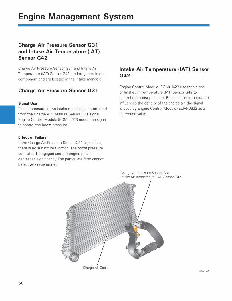
Charge Air Pressure Sensor G31 and Intake Air Temperature (IAT) Sensor G42
Charge Air Pressure Sensor G31 and Intake Air Temperature (IAT) Sensor G42 are integrated in one component and are located in the intake manifold.
Charge Air Pressure Sensor G31
Signal UseThe air pressure in the intake manifold is determined from the Charge Air Pressure Sensor G31 signal. Engine Control Module (ECM) J623 needs the signal to control the boost pressure.
Effect of FailureIf the Charge Air Pressure Sensor G31 signal fails, there is no substitute function. The boost pressure control is disengaged and the engine power decreases signifi cantly. The particulate fi lter cannot be actively regenerated.
Intake Air Temperature (IAT) Sensor G42
Engine Control Module (ECM) J623 uses the signal of Intake Air Temperature (IAT) Sensor G42 to control the boost pressure. Because the temperature infl uences the density of the charge air, the signal is used by Engine Control Module (ECM) J623 as a correction value.
S403_096
Charge Air Pressure Sensor G31 Intake Air Temperature (IAT) Sensor G42
Charge Air Cooler
51
Engine Management System
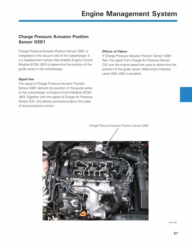
Charge Pressure Actuator Position Sensor G581
Charge Pressure Actuator Position Sensor G581 is integrated in the vacuum cell of the turbocharger. It is a displacement sensor that enables Engine Control Module (ECM) J623 to determine the position of the guide vanes in the turbocharger.
Signal UseThe signal of Charge Pressure Actuator Position Sensor G581 delivers the position of the guide vanes of the turbocharger to Engine Control Module (ECM) J623. Together with the signal of Charge Air Pressure Sensor G31, this allows conclusions about the state of boost pressure control.
Charge Pressure Actuator Position Sensor G581
S403_095
Effects of FailureIf Charge Pressure Actuator Position Sensor G581 fails, the signal from Charge Air Pressure Sensor G31 and the engine speed are used to determine the position of the guide vanes. Malfunction Indicator Lamp (MIL) K83 is actuated.
52
Engine Management System
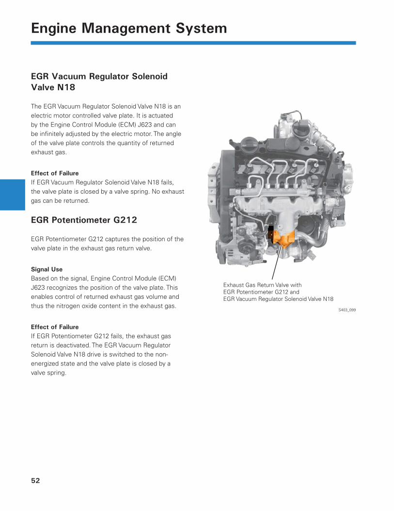
EGR Vacuum Regulator Solenoid Valve N18
The EGR Vacuum Regulator Solenoid Valve N18 is an electric motor controlled valve plate. It is actuated by the Engine Control Module (ECM) J623 and can be infi nitely adjusted by the electric motor. The angle of the valve plate controls the quantity of returned exhaust gas.
Effect of FailureIf EGR Vacuum Regulator Solenoid Valve N18 fails, the valve plate is closed by a valve spring. No exhaust gas can be returned.
EGR Potentiometer G212
EGR Potentiometer G212 captures the position of the valve plate in the exhaust gas return valve.
Signal UseBased on the signal, Engine Control Module (ECM) J623 recognizes the position of the valve plate. This enables control of returned exhaust gas volume and thus the nitrogen oxide content in the exhaust gas.
Effect of FailureIf EGR Potentiometer G212 fails, the exhaust gas return is deactivated. The EGR Vacuum Regulator Solenoid Valve N18 drive is switched to the non-energized state and the valve plate is closed by a valve spring.
S403_099
Exhaust Gas Return Valve with EGR Potentiometer G212 and EGR Vacuum Regulator Solenoid Valve N18
53
Engine Management System
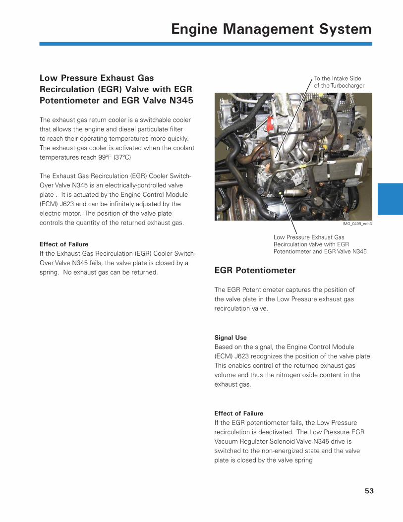
Low Pressure Exhaust Gas Recirculation (EGR) Valve with EGR Potentiometer and EGR Valve N345
The exhaust gas return cooler is a switchable cooler that allows the engine and diesel particulate fi lter to reach their operating temperatures more quickly. The exhaust gas cooler is activated when the coolant temperatures reach 99ºF (37ºC)
The Exhaust Gas Recirculation (EGR) Cooler Switch-Over Valve N345 is an electrically-controlled valve plate . It is actuated by the Engine Control Module (ECM) J623 and can be infi nitely adjusted by the electric motor. The position of the valve plate controls the quantity of the returned exhaust gas.
Effect of FailureIf the Exhaust Gas Recirculation (EGR) Cooler Switch-Over Valve N345 fails, the valve plate is closed by a spring. No exhaust gas can be returned.
Low Pressure Exhaust Gas Recirculation Valve with EGR Potentiometer and EGR Valve N345
IMG_0408_edit3
To the Intake Side of the Turbocharger
EGR Potentiometer
The EGR Potentiometer captures the position of the valve plate in the Low Pressure exhaust gas recirculation valve.
Signal UseBased on the signal, the Engine Control Module (ECM) J623 recognizes the position of the valve plate. This enables control of the returned exhaust gas volume and thus the nitrogen oxide content in the exhaust gas.
Effect of FailureIf the EGR potentiometer fails, the Low Pressure recirculation is deactivated. The Low Pressure EGR Vacuum Regulator Solenoid Valve N345 drive is switched to the non-energized state and the valve plate is closed by the valve spring
54
Engine Management System
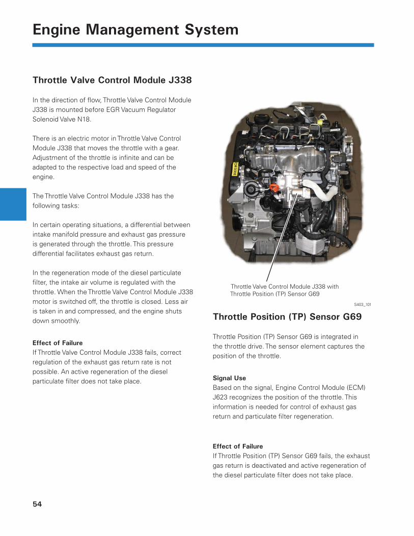
Throttle Valve Control Module J338
In the direction of fl ow, Throttle Valve Control Module J338 is mounted before EGR Vacuum Regulator Solenoid Valve N18.
There is an electric motor in Throttle Valve Control Module J338 that moves the throttle with a gear. Adjustment of the throttle is infi nite and can be adapted to the respective load and speed of the engine.
The Throttle Valve Control Module J338 has the following tasks:
In certain operating situations, a differential between intake manifold pressure and exhaust gas pressure is generated through the throttle. This pressure differential facilitates exhaust gas return.
In the regeneration mode of the diesel particulate fi lter, the intake air volume is regulated with the throttle. When the Throttle Valve Control Module J338 motor is switched off, the throttle is closed. Less air is taken in and compressed, and the engine shuts down smoothly.
Effect of FailureIf Throttle Valve Control Module J338 fails, correct regulation of the exhaust gas return rate is not possible. An active regeneration of the diesel particulate fi lter does not take place.
S403_101
Throttle Position (TP) Sensor G69
Throttle Position (TP) Sensor G69 is integrated in the throttle drive. The sensor element captures the position of the throttle.
Signal UseBased on the signal, Engine Control Module (ECM) J623 recognizes the position of the throttle. This information is needed for control of exhaust gas return and particulate fi lter regeneration.
Effect of FailureIf Throttle Position (TP) Sensor G69 fails, the exhaust gas return is deactivated and active regeneration of the diesel particulate fi lter does not take place.
Throttle Valve Control Module J338 withThrottle Position (TP) Sensor G69
55
Engine Management System
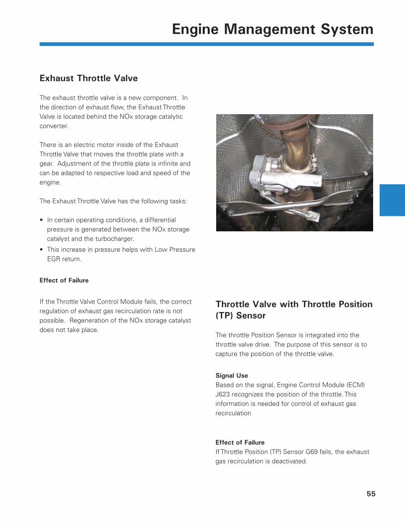
Exhaust Throttle Valve
The exhaust throttle valve is a new component. In the direction of exhaust fl ow, the Exhaust Throttle Valve is located behind the NOx storage catalytic converter.
There is an electric motor inside of the Exhaust Throttle Valve that moves the throttle plate with a gear. Adjustment of the throttle plate is infi nite and can be adapted to respective load and speed of the engine.
The Exhaust Throttle Valve has the following tasks:
In certain operating conditions, a differential pressure is generated between the NOx storage catalyst and the turbocharger.
This increase in pressure helps with Low Pressure EGR return.
Effect of Failure
If the Throttle Valve Control Module fails, the correct regulation of exhaust gas recirculation rate is not possible. Regeneration of the NOx storage catalyst does not take place.
•
•
Throttle Valve with Throttle Position (TP) Sensor
The throttle Position Sensor is integrated into the throttle valve drive. The purpose of this sensor is to capture the position of the throttle valve.
Signal UseBased on the signal, Engine Control Module (ECM) J623 recognizes the position of the throttle. This information is needed for control of exhaust gas recirculation
Effect of FailureIf Throttle Position (TP) Sensor G69 fails, the exhaust gas recirculation is deactivated.
56
Engine Management System
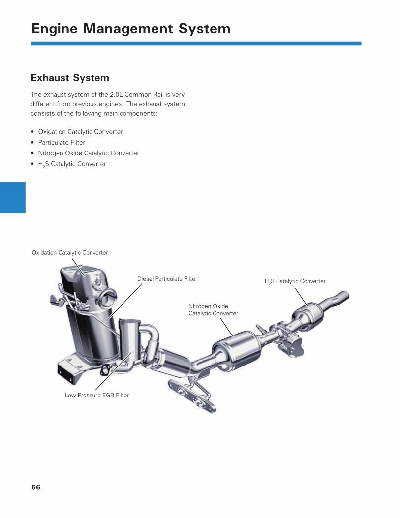
Exhaust System
The exhaust system of the 2.0L Common-Rail is very different from previous engines. The exhaust system consists of the following main components:
Oxidation Catalytic Converter
Particulate Filter
Nitrogen Oxide Catalytic Converter
H2S Catalytic Converter
•
•
•
•
Oxidation Catalytic Converter
Diesel Particulate Filter
Nitrogen Oxide Catalytic Converter
H2S Catalytic Converter
Low Pressure EGR Filter
Differential Pressure Sensor Pipes
57
Engine Management System
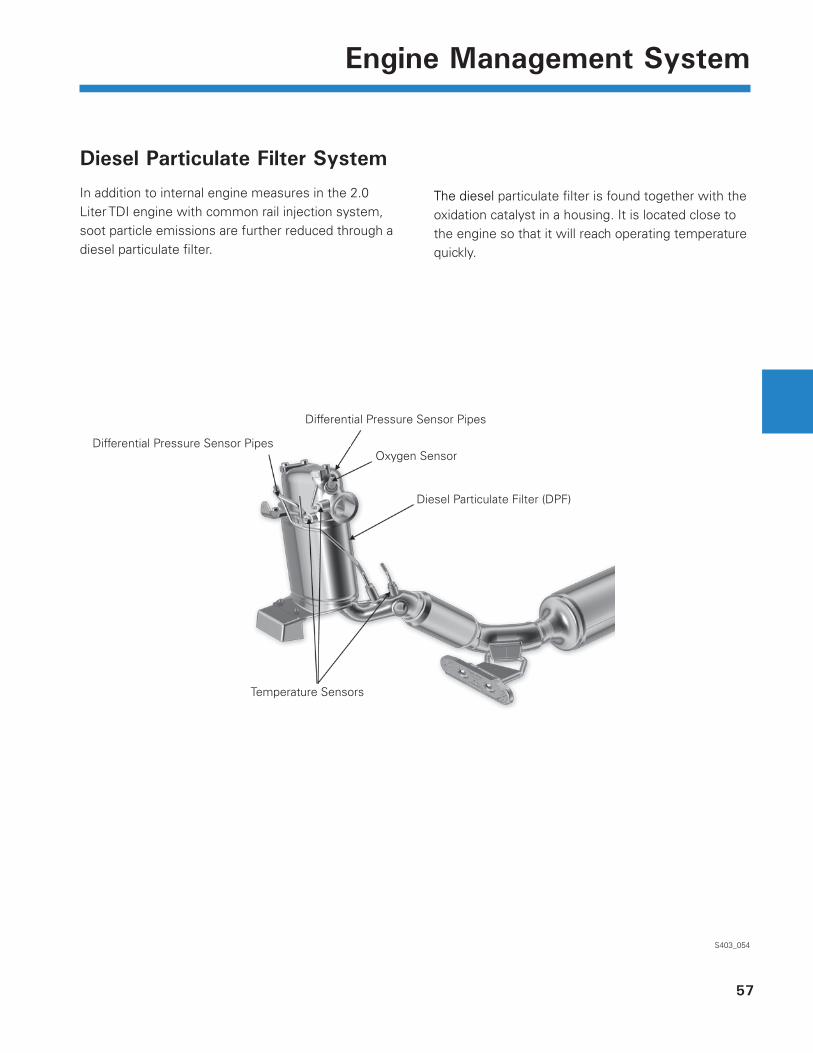
Diesel Particulate Filter System
In addition to internal engine measures in the 2.0 Liter TDI engine with common rail injection system, soot particle emissions are further reduced through a diesel particulate fi lter.
S403_054
The diesel particulate fi lter is found together with the oxidation catalyst in a housing. It is located close to the engine so that it will reach operating temperature quickly.
Differential Pressure Sensor Pipes
Temperature Sensors
Oxygen Sensor
Diesel Particulate Filter (DPF)
58
Engine Management System
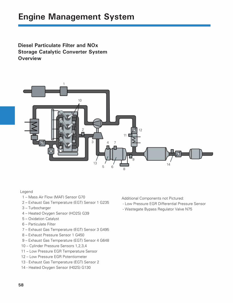
Diesel Particulate Filter and NOx Storage Catalytic Converter System Overview
Legend 1 – Mass Air Flow (MAF) Sensor G70 2 – Exhaust Gas Temperature (EGT) Sensor 1 G235 3 – Turbocharger 4 – Heated Oxygen Sensor (HO2S) G39 5 – Oxidation Catalyst 6 – Particulate Filter 7 – Exhaust Gas Temperature (EGT) Sensor 3 G495 8 – Exhaust Pressure Sensor 1 G450 9 – Exhaust Gas Temperature (EGT) Sensor 4 G648 10 – Cylinder Pressure Sensors 1,2,3,4 11 – Low Pressure EGR Temperature Sensor 12 – Low Pressure EGR Potentiometer 13 - Exhaust Gas Temperature (EGT) Sensor 2 14 - Heated Oxygen Sensor (H02S) G130
Additional Components not Pictured: - Low Pressure EGR Differential Pressure Sensor - Wastegate Bypass Regulator Valve N75
4
6
7
11
2
1
3
9
10
58
12
13 14
59
Engine Management System
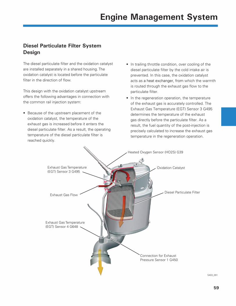
Diesel Particulate Filter System Design
The diesel particulate fi lter and the oxidation catalyst are installed separately in a shared housing. The oxidation catalyst is located before the particulate fi lter in the direction of fl ow.
This design with the oxidation catalyst upstream offers the following advantages in connection with the common rail injection system:
Because of the upstream placement of the oxidation catalyst, the temperature of the exhaust gas is increased before it enters the diesel particulate fi lter. As a result, the operating temperature of the diesel particulate fi lter is reached quickly.
•
S403_091
In trailing throttle condition, over cooling of the diesel particulate fi lter by the cold intake air is prevented. In this case, the oxidation catalyst acts as a heat exchanger, from which the warmth is routed through the exhaust gas fl ow to the particulate fi lter.
In the regeneration operation, the temperature of the exhaust gas is accurately controlled. The Exhaust Gas Temperature (EGT) Sensor 3 G495 determines the temperature of the exhaust gas directly before the particulate fi lter. As a result, the fuel quantity of the post-injection is precisely calculated to increase the exhaust gas temperature in the regeneration operation.
•
•
Heated Oxygen Sensor (HO2S) G39
Exhaust Gas Temperature (EGT) Sensor 3 G495
Exhaust Gas Flow
Exhaust Gas Temperature (EGT) Sensor 4 G648
Oxidation Catalyst
Diesel Particulate Filter
Connection for Exhaust Pressure Sensor 1 G450
60
Engine Management System
Oxidation Catalyst
The carrier material of the oxidation catalyst is metal, so the light-off temperature is reached quickly. This metal body has an aluminum oxide carrier coating, onto which platinum and palladium are vapor-deposited as catalyst for the hydrocarbons (HC) and the carbon monoxide (CO).
FunctionThe oxidation catalyst converts a large portion of the hydrocarbons (HC) and the carbon monoxide (CO) into water vapor and carbon dioxide.
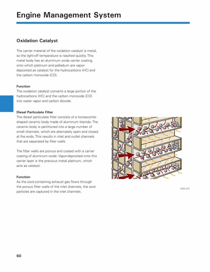
Diesel Particulate FilterThe diesel particulate fi lter consists of a honeycomb-shaped ceramic body made of aluminum titanide. The ceramic body is partitioned into a large number of small channels, which are alternately open and closed at the ends. This results in inlet and outlet channels that are separated by fi lter walls.
The fi lter walls are porous and coated with a carrier coating of aluminum oxide. Vapor-deposited onto this carrier layer is the precious metal platinum, which acts as catalyst.
FunctionAs the soot-containing exhaust gas fl ows through the porous fi lter walls of the inlet channels, the soot particles are captured in the inlet channels.
S403_072
61
Engine Management System
Regeneration
The particulate fi lter must be regenerated regularly so that it does not become clogged with soot particles and its function impaired. During regeneration, the soot particles collected in the particulate fi lter are burned off (oxidized).
The regeneration of the particulate fi lter is performed in the following stages:
Warm-up phase
Passive regeneration
Active regeneration
Customer-initiated regeneration drive
Service regeneration
Warm-Up PhaseTo heat up a cold oxidation catalyst and particulate fi lter as quickly as possible and thus bring them to operating temperature, the engine management system introduces a post-injection after the main injection.
This fuel combusts in the cylinder and increases the combustion temperature. Through the air fl ow in the exhaust gas tract, the resulting heat reaches the oxidation catalyst and the particulate fi lter and heats them.
The warm-up phase is complete when the operating temperature of the oxidation catalyst and the particulate fi lter has been reached for a specifi c period of time.
•
•
•
•
•
Passive RegenerationDuring passive regeneration the soot particles are continuously burned without the intervention of Engine Control Module (ECM) J623.
This occurs primarily at higher engine load, such as in highway driving, when exhaust gas temperatures range from 662°F to 932°F (350°C to 500°C).
At these temperatures the soot particles are converted into carbon dioxide through a combustion reaction with nitrogen dioxide.
62
Engine Management System
Active Regeneration
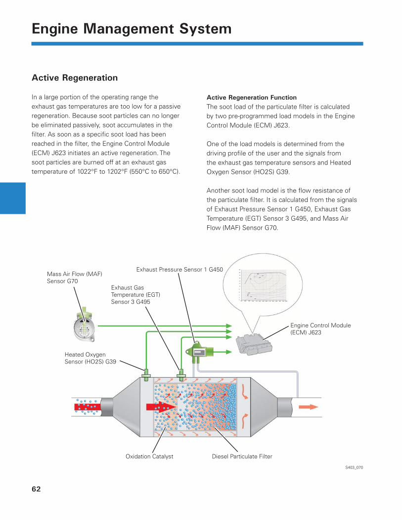
In a large portion of the operating range the exhaust gas temperatures are too low for a passive regeneration. Because soot particles can no longer be eliminated passively, soot accumulates in the fi lter. As soon as a specifi c soot load has been reached in the fi lter, the Engine Control Module (ECM) J623 initiates an active regeneration. The soot particles are burned off at an exhaust gas temperature of 1022°F to 1202°F (550°C to 650°C).
S403_070
Active Regeneration FunctionThe soot load of the particulate fi lter is calculated by two pre-programmed load models in the Engine Control Module (ECM) J623.
One of the load models is determined from the driving profi le of the user and the signals from the exhaust gas temperature sensors and Heated Oxygen Sensor (HO2S) G39.
Another soot load model is the fl ow resistance of the particulate fi lter. It is calculated from the signals of Exhaust Pressure Sensor 1 G450, Exhaust Gas Temperature (EGT) Sensor 3 G495, and Mass Air Flow (MAF) Sensor G70.
Exhaust Pressure Sensor 1 G450
Exhaust GasTemperature (EGT) Sensor 3 G495
Heated Oxygen Sensor (HO2S) G39
Mass Air Flow (MAF)Sensor G70
Oxidation Catalyst Diesel Particulate Filter
Engine Control Module(ECM) J623
63
Engine Management System
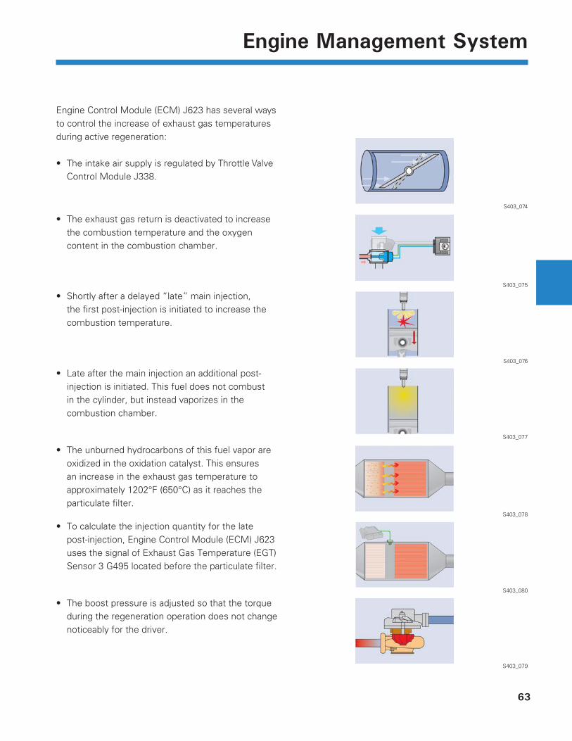
Engine Control Module (ECM) J623 has several ways to control the increase of exhaust gas temperatures during active regeneration:
The intake air supply is regulated by Throttle Valve Control Module J338.
•
S403_079
S403_080
S403_078
S403_077
S403_076
S403_075
S403_074
The exhaust gas return is deactivated to increase the combustion temperature and the oxygen content in the combustion chamber.
•
Shortly after a delayed “late” main injection, the fi rst post-injection is initiated to increase the combustion temperature.
•
Late after the main injection an additional post-injection is initiated. This fuel does not combust in the cylinder, but instead vaporizes in the combustion chamber.
•
The unburned hydrocarbons of this fuel vapor are oxidized in the oxidation catalyst. This ensures an increase in the exhaust gas temperature to approximately 1202°F (650°C) as it reaches the particulate fi lter.
•
To calculate the injection quantity for the late post-injection, Engine Control Module (ECM) J623 uses the signal of Exhaust Gas Temperature (EGT) Sensor 3 G495 located before the particulate fi lter.
•
The boost pressure is adjusted so that the torque during the regeneration operation does not change noticeably for the driver.
•
64
Engine Management System
Customer-Initiated Regeneration Drive
An exhaust gas temperature high enough for particulate fi lter regeneration is not reached when the vehicle is only driven for short-distances. If the load condition of the diesel particulate fi lter reaches a threshold value, Diesel Particle Filter Indicator Lamp K231 in the instrument panel will light up.
This signal prompts the driver to perform a regeneration drive. The vehicle must be driven for a short period of time at increased speed to ensure that an adequately high exhaust gas temperature is reached. The operating conditions must remain constant over the period for a successful regeneration.
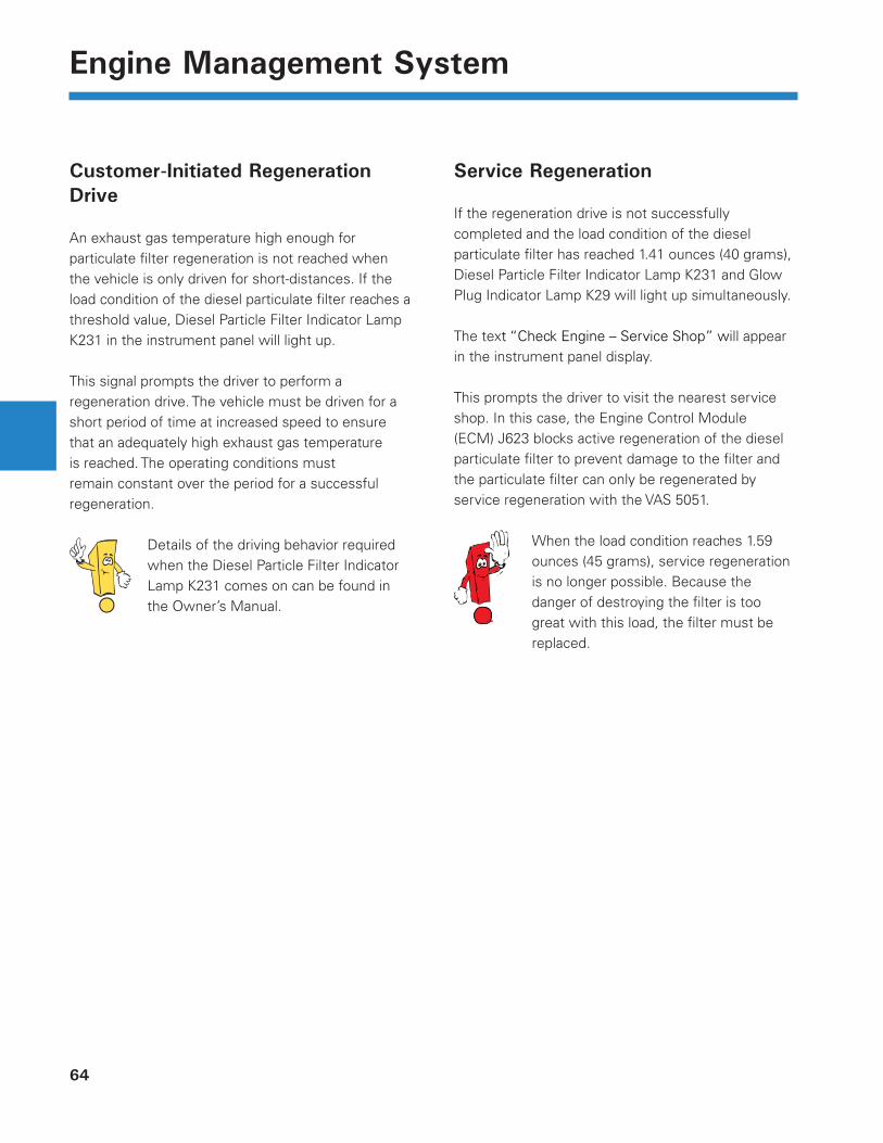
Details of the driving behavior required when the Diesel Particle Filter Indicator Lamp K231 comes on can be found in the Owner’s Manual.
Service Regeneration
If the regeneration drive is not successfully completed and the load condition of the diesel particulate fi lter has reached 1.41 ounces (40 grams), Diesel Particle Filter Indicator Lamp K231 and Glow Plug Indicator Lamp K29 will light up simultaneously.
The text “Check Engine – Service Shop” will appear in the instrument panel display.
This prompts the driver to visit the nearest service shop. In this case, the Engine Control Module (ECM) J623 blocks active regeneration of the diesel particulate fi lter to prevent damage to the fi lter and the particulate fi lter can only be regenerated by service regeneration with the VAS 5051.
When the load condition reaches 1.59 ounces (45 grams), service regeneration is no longer possible. Because the danger of destroying the fi lter is too great with this load, the fi lter must be replaced.
65
Engine Management System
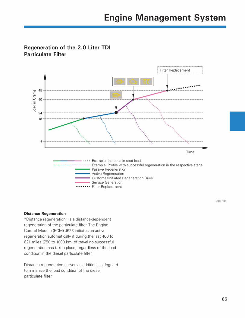
Regeneration of the 2.0 Liter TDI Particulate Filter
S403_105
Load
in G
ram
s
Time
Filter Replacement
Example: Increase in soot loadExample: Profi le with successful regeneration in the respective stagePassive RegenerationActive RegenerationCustomer-Initiated Regeneration DriveService GenerationFilter Replacement
Distance Regeneration“Distance regeneration” is a distance-dependent regeneration of the particulate fi lter. The Engine Control Module (ECM) J623 initiates an active regeneration automatically if during the last 466 to 621 miles (750 to 1000 km) of travel no successful regeneration has taken place, regardless of the load condition in the diesel particulate fi lter.
Distance regeneration serves as additional safeguard to minimize the load condition of the diesel particulate fi lter.
66
Engine Management System
Nitrogen Oxide Catalytic Converter
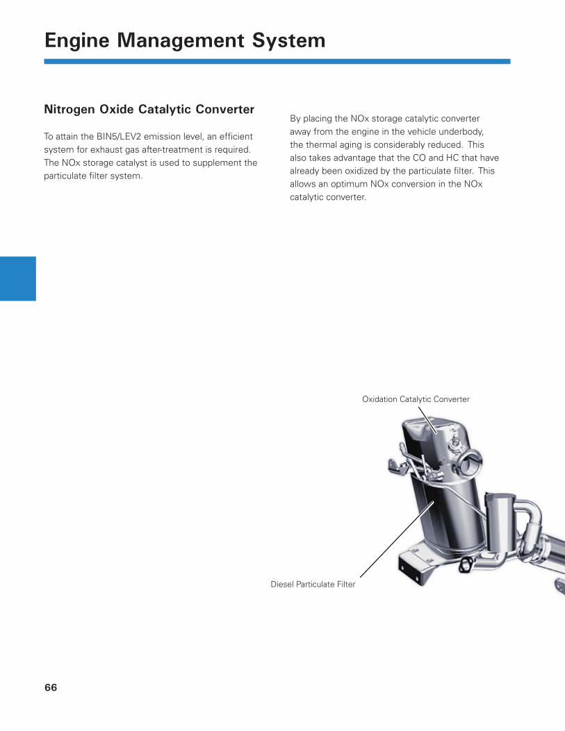
To attain the BIN5/LEV2 emission level, an effi cient system for exhaust gas after-treatment is required. The NOx storage catalyst is used to supplement the particulate fi lter system.
Oxidation Catalytic Converter
Diesel Particulate Filter
By placing the NOx storage catalytic converter away from the engine in the vehicle underbody, the thermal aging is considerably reduced. This also takes advantage that the CO and HC that have already been oxidized by the particulate fi lter. This allows an optimum NOx conversion in the NOx catalytic converter.
67
Engine Management System
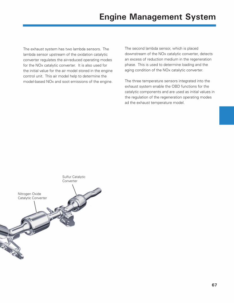
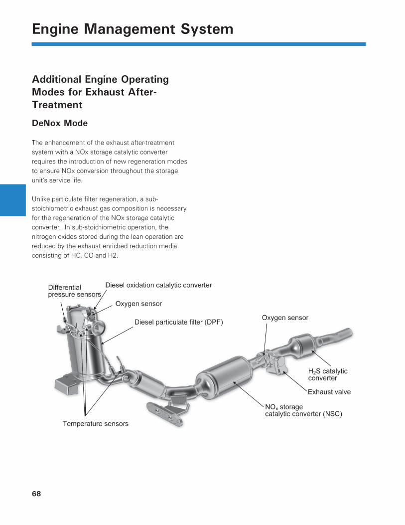
Nitrogen Oxide Catalytic Converter
Sulfur Catalytic Converter
The exhaust system has two lambda sensors. The lambda sensor upstream of the oxidation catalytic converter regulates the air-reduced operating modes for the NOx catalytic converter. It is also used for the initial value for the air model stored in the engine control unit. This air model help to determine the model-based NOx and soot emissions of the engine.
The second lambda sensor, which is placed downstream of the NOx catalytic converter, detects an excess of reduction medium in the regeneration phase. This is used to determine loading and the aging condition of the NOx catalytic converter.
The three temperature sensors integrated into the exhaust system enable the OBD functions for the catalytic components and are used as initial values in the regulation of the regeneration operating modes ad the exhaust temperature model.
68
Engine Management System
Additional Engine Operating Modes for Exhaust After-Treatment
DeNox Mode
The enhancement of the exhaust after-treatment system with a NOx storage catalytic converter requires the introduction of new regeneration modes to ensure NOx conversion throughout the storage unit’s service life.
Unlike particulate fi lter regeneration, a sub-stoichiometric exhaust gas composition is necessary for the regeneration of the NOx storage catalytic converter. In sub-stoichiometric operation, the nitrogen oxides stored during the lean operation are reduced by the exhaust enriched reduction media consisting of HC, CO and H2.
69
Engine Management System
DeSOx Mode
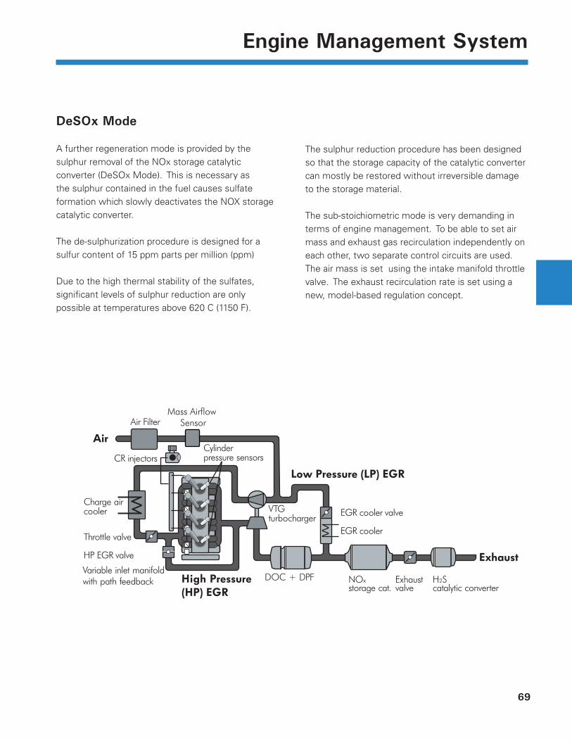
A further regeneration mode is provided by the sulphur removal of the NOx storage catalytic converter (DeSOx Mode). This is necessary as the sulphur contained in the fuel causes sulfate formation which slowly deactivates the NOX storage catalytic converter.
The de-sulphurization procedure is designed for a sulfur content of 15 ppm parts per million (ppm)
Due to the high thermal stability of the sulfates, signifi cant levels of sulphur reduction are only possible at temperatures above 620 C (1150 F).
The sulphur reduction procedure has been designed so that the storage capacity of the catalytic converter can mostly be restored without irreversible damage to the storage material.
The sub-stoichiometric mode is very demanding in terms of engine management. To be able to set air mass and exhaust gas recirculation independently on each other, two separate control circuits are used. The air mass is set using the intake manifold throttle valve. The exhaust recirculation rate is set using a new, model-based regulation concept.
Air Filter
CR injectors
Throttle valve
HP EGR valve
Variable inlet manifold with path feedback
Charge aircooler
Cylinderpressure sensors
VTGturbocharger
DOC + DPF
EGR cooler
EGR cooler valve
Exhaust
Low Pressure (LP) EGR
High Pressure (HP) EGR
Air
NOxstorage cat.
H2Scatalytic converter
Exhaustvalve
Mass Airflow Sensor
70
Engine Management System
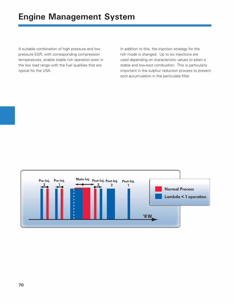
A suitable combination of high pressure and low pressure EGR, with corresponding compression temperatures, enable stable rich operation even in the low load range with the fuel qualities that are typical for the USA.
In addition to this, the injection strategy for the rich mode is changed. Up to six injections are used depending on characteristic values to attain a stable and low-soot combustion. This is particularly important in the sulphur reduction process to prevent soot accumulation in the particulate fi lter.
71
Engine Management System
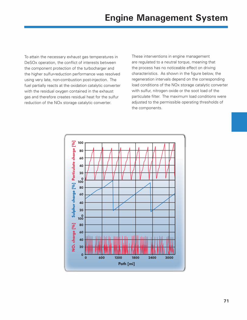
To attain the necessary exhaust gas temperatures in DeSOx operation, the confl ict of interests between the component protection of the turbocharger and the higher sulfur-reduction performance was resolved using very late, non-combustion post-injection. The fuel partially reacts at the oxidation catalytic converter with the residual oxygen contained in the exhaust gas and therefore creates residual heat for the sulfur reduction of the NOx storage catalytic converter.
These interventions in engine management are regulated to a neutral torque, meaning that the process has no noticeable effect on driving characteristics. As shown in the fi gure below, the regeneration intervals depend on the corresponding load conditions of the NOx storage catalytic converter with sulfur, nitrogen oxide or the soot load of the particulate fi lter. The maximum load conditions were adjusted to the permissible operating thresholds of the components.
100
80
60
40
20
0100
80
60
40
20
1000
80
60
40
20
0 600 1200
Path [mi]
NO
x ch
arge
[%
]Su
lphu
r ch
arge
[%
]Pa
rtic
ulat
e ch
arge
[%
]
1800 2400 30000
72
Engine Management System
DeNOx Concept
Taking the necessary engine operation and regeneration conditions as well as the catalytic converter properties into consideration, the corresponding regeneration mode is prioritized by a coordination program in the engine control module.
DeNOx regeneration is given a higher priority than other regenerations to prevent thermal NOx desorption.
A loading and discharging model is stored in the engine control module for DeNOx regeneration. This maps the characteristics of the DeNOx storage catalytic converter. The load condition of the catalytic converter is modeled during engine operation that is dependent on the exhaust temperature and volume velocity as well as the calculated raw NOx emissions.
If the NOx load value exceeds a threshold value which represents the optimum conversion rate for the catalytic converter, the regeneration is conducted when the operating condition of the engine permits a regeneration mode to be activated.
Two criteria, which relate to the lambda signal or a NOx discharge model, are available for determining the end of regeneration.
As soon as the lambda sensor detects a rise in the reduction medium after the NOx storage catalytic converter, it is free of nitrogen oxide and regeneration has ended.
Due to cross-sensitivity of the lambda probe, this criteria is not permissible under a certain threshold temperature. For this reason, the discharge of the NOx storage catalytic converter is also modeled on the basis of the requirement and provision of reduction medium to reduce the stored NOx.
73
Engine Management System
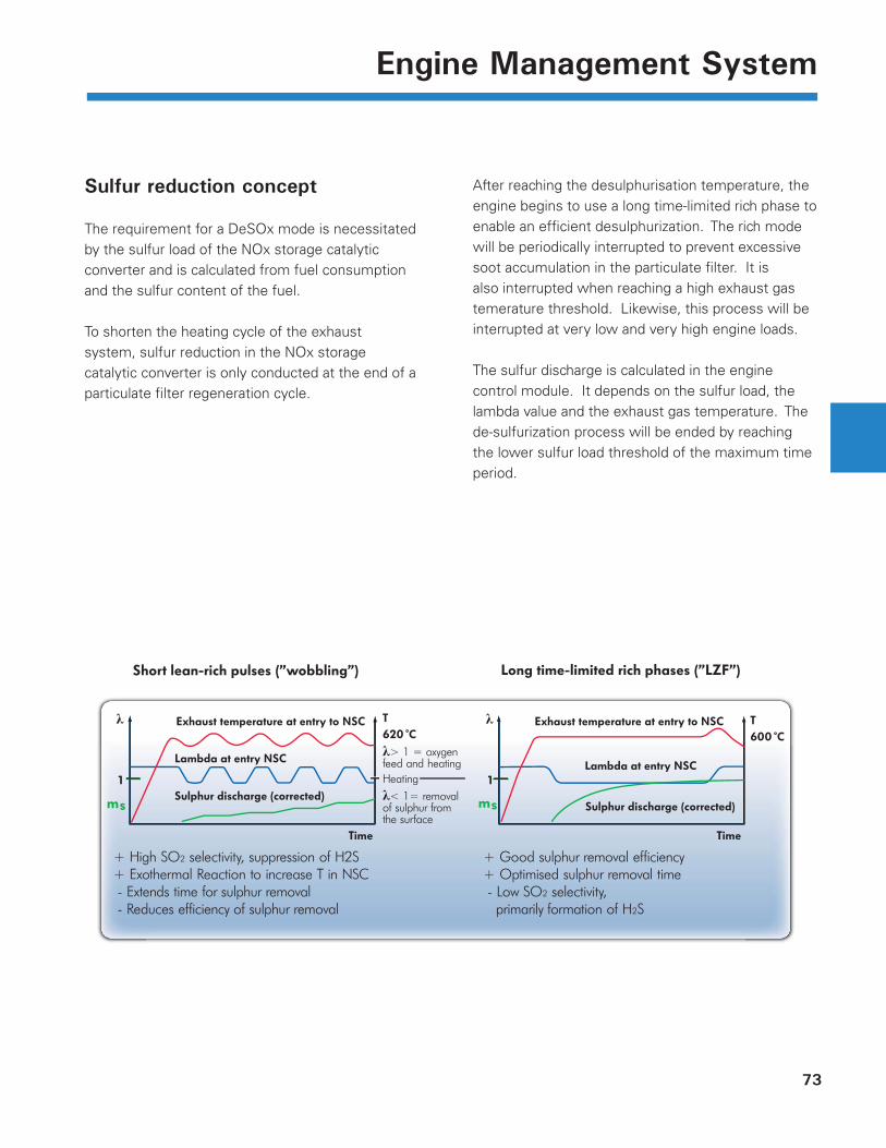
Sulfur reduction concept
The requirement for a DeSOx mode is necessitated by the sulfur load of the NOx storage catalytic converter and is calculated from fuel consumption and the sulfur content of the fuel.
To shorten the heating cycle of the exhaust system, sulfur reduction in the NOx storage catalytic converter is only conducted at the end of a particulate fi lter regeneration cycle.
After reaching the desulphurisation temperature, the engine begins to use a long time-limited rich phase to enable an effi cient desulphurization. The rich mode will be periodically interrupted to prevent excessive soot accumulation in the particulate fi lter. It is also interrupted when reaching a high exhaust gas temerature threshold. Likewise, this process will be interrupted at very low and very high engine loads.
The sulfur discharge is calculated in the engine control module. It depends on the sulfur load, the lambda value and the exhaust gas temperature. The de-sulfurization process will be ended by reaching the lower sulfur load threshold of the maximum time period.
Exhaust temperature at entry to NSC Exhaust temperature at entry to NSC
Sulphur discharge (corrected)Sulphur discharge (corrected)
Lambda at entry NSCLambda at entry NSC
620˚CT
600˚CT
Time Time
1
λ
1
λ
ms msλ< 1= removalof sulphur from the surface
λ> 1 = oxygen feed and heating Heating
Long time-limited rich phases (”LZF”)Short lean-rich pulses (”wobbling”)
+ High SO2 selectivity, suppression of H2S+ Exothermal Reaction to increase T in NSC - Extends time for sulphur removal - Reduces efficiency of sulphur removal
+ Good sulphur removal efficiency+ Optimised sulphur removal time - Low SO2 selectivity, primarily formation of H2S
74
Engine Management System
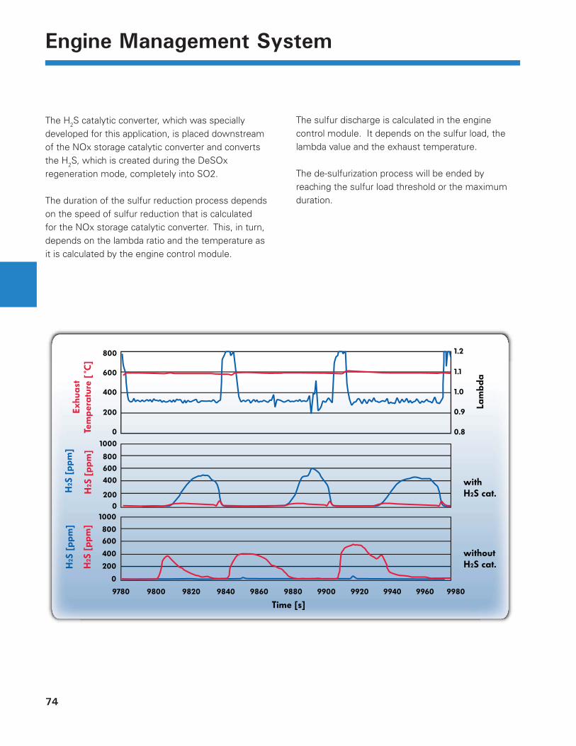
The H2S catalytic converter, which was specially developed for this application, is placed downstream of the NOx storage catalytic converter and converts the H2S, which is created during the DeSOx regeneration mode, completely into SO2.
The duration of the sulfur reduction process depends on the speed of sulfur reduction that is calculated for the NOx storage catalytic converter. This, in turn, depends on the lambda ratio and the temperature as it is calculated by the engine control module.
The sulfur discharge is calculated in the engine control module. It depends on the sulfur load, the lambda value and the exhaust temperature.
The de-sulfurization process will be ended by reaching the sulfur load threshold or the maximum duration.
Exhu
ast
Tem
per
atur
e [˚
C]
H2S
[p
pm
]
H2S
[p
pm
]
Lam
bda
withH2S cat.
withoutH2S cat.
Time [s]
H2S
[p
pm
]
H2S
[p
pm
]
800 1.2
1.1
1.0
0.9
0.8
600
400
200
0
1000
800
600
400
200
0
800
1000
600
400
200
0
9780 9800 9820 9840 9860 9880 9900 9920 9940 9960 9980

75
Notes
76
Engine Management System
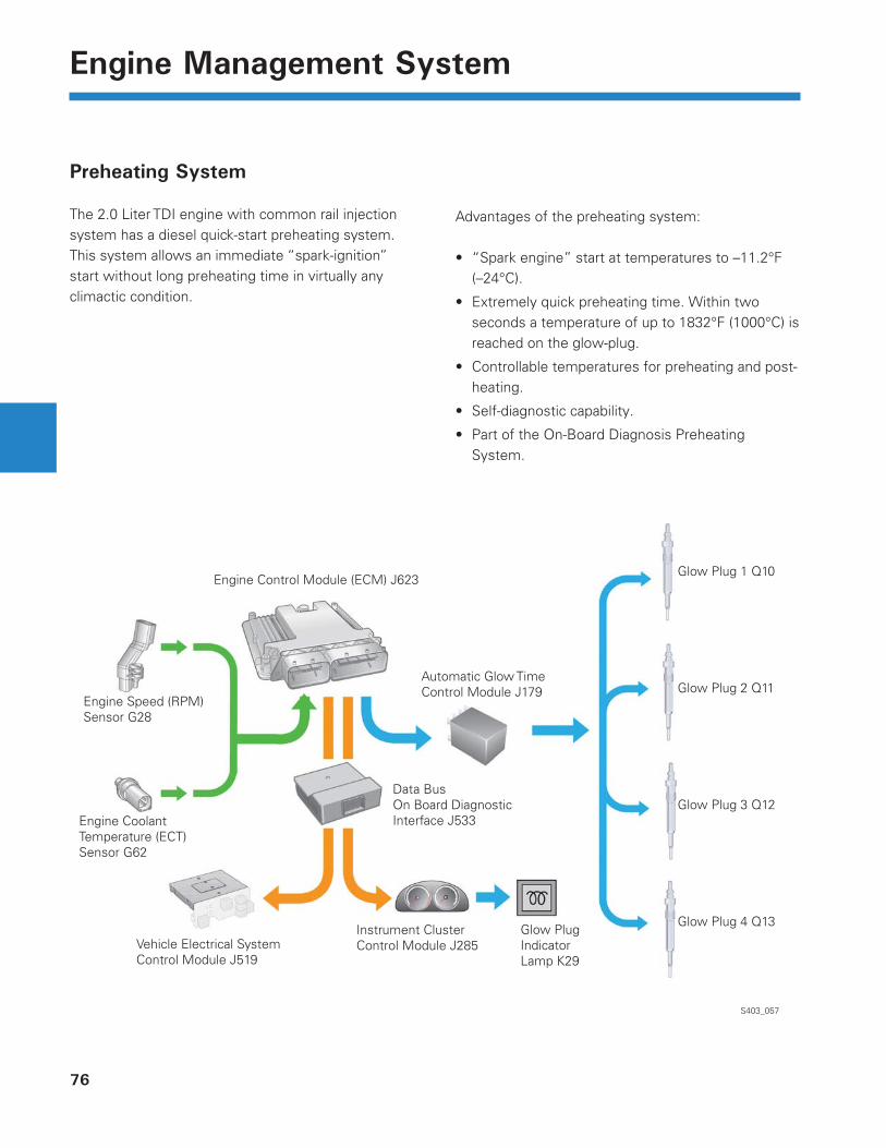
Preheating System
The 2.0 Liter TDI engine with common rail injection system has a diesel quick-start preheating system. This system allows an immediate “spark-ignition” start without long preheating time in virtually any climactic condition.
S403_057
Glow Plug 4 Q13
Glow Plug 3 Q12
Glow Plug 2 Q11
Glow Plug 1 Q10
Engine Speed (RPM) Sensor G28
Engine Coolant Temperature (ECT) Sensor G62
Vehicle Electrical System Control Module J519
Glow PlugIndicator Lamp K29
Instrument ClusterControl Module J285
Data BusOn Board Diagnostic Interface J533
Automatic Glow Time Control Module J179
Engine Control Module (ECM) J623
Advantages of the preheating system:
“Spark engine” start at temperatures to –11.2°F (–24°C).
Extremely quick preheating time. Within two seconds a temperature of up to 1832°F (1000°C) is reached on the glow-plug.
Controllable temperatures for preheating and post-heating.
Self-diagnostic capability.
Part of the On-Board Diagnosis Preheating System.
•
•
•
•
•
77
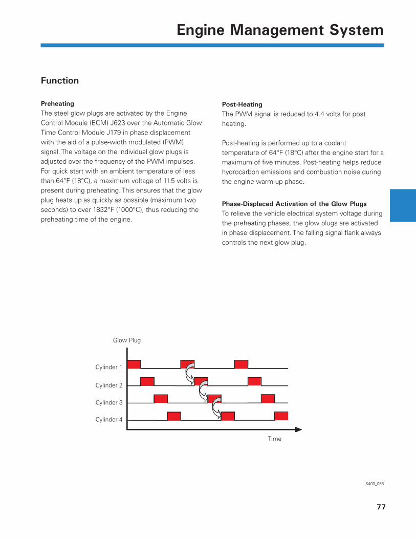
Engine Management System
Function
PreheatingThe steel glow plugs are activated by the Engine Control Module (ECM) J623 over the Automatic Glow Time Control Module J179 in phase displacement with the aid of a pulse-width modulated (PWM) signal. The voltage on the individual glow plugs is adjusted over the frequency of the PWM impulses. For quick start with an ambient temperature of less than 64°F (18°C), a maximum voltage of 11.5 volts is present during preheating. This ensures that the glow plug heats up as quickly as possible (maximum two seconds) to over 1832°F (1000°C), thus reducing the preheating time of the engine.
S403_056
Post-HeatingThe PWM signal is reduced to 4.4 volts for post heating.
Post-heating is performed up to a coolant temperature of 64°F (18°C) after the engine start for a maximum of fi ve minutes. Post-heating helps reduce hydrocarbon emissions and combustion noise during the engine warm-up phase.
Phase-Displaced Activation of the Glow PlugsTo relieve the vehicle electrical system voltage during the preheating phases, the glow plugs are activated in phase displacement. The falling signal fl ank always controls the next glow plug.
Time
Glow Plug
Cylinder 1
Cylinder 2
Cylinder 3
Cylinder 4
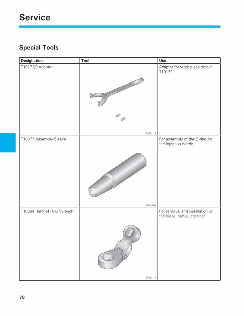
78
ServiceService
Special Tools
Designation Tool Use
T10172/9 Adapter
S403_113
Adapter for work piece holder T10172
T10377 Assembly Sleeve
S403_068
For assembly of the O-ring on the injection nozzle
T10384 Ratchet Ring Wrench
S403_114
For removal and installation of the diesel particulate fi lter
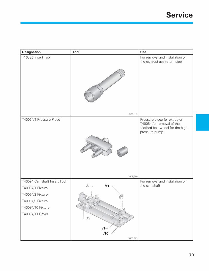
79
Service
Designation Tool Use
T10385 Insert Tool
S403_112
For removal and installation of the exhaust gas return pipe
T40064/1 Pressure Piece
S403_066
Pressure piece for extractor T40064 for removal of the toothed-belt wheel for the high-pressure pump
T40094 Camshaft Insert Tool
T40094/1 Fixture
T40094/2 Fixture
T40094/9 Fixture
T40094/10 Fixture
T40094/11 Cover
S403_063
For removal and installation of the camshaft
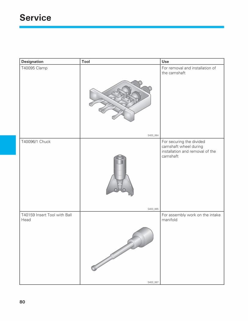
80
Service
Designation Tool Use
T40095 Clamp
S403_064
For removal and installation of the camshaft
T40096/1 Chuck
S403_065
For securing the divided camshaft wheel during installation and removal of the camshaft
T40159 Insert Tool with Ball Head
S403_067
For assembly work on the intake manifold
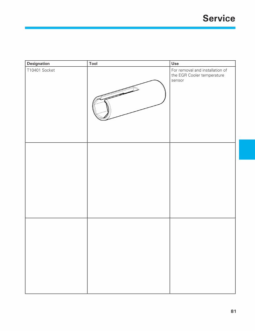
81
Service
Designation Tool Use
T10401 Socket For removal and installation of the EGR Cooler temperature sensor

82
Notes
83
Knowledge AssessmentKnowledge Assessment
An on-line Knowledge Assessment (exam) is available for this Self-Study Program.
The Knowledge Assessment may or may not be required for Certifi cation.
You can fi nd this Knowledge Assessment at:
www.vwwebsource.com
For Assistance, please call:
Volkswagen Academy
Certification Program Headquarters
1-877-491-4838
(8:00 a.m. to 8:00 p.m. EST)
Or, E-Mail:


Volkswagen of America, Inc.3800 Hamlin RoadAuburn Hills, MI 48326Printed in the U.S.A.April 2008