Embed Size (px)
Citation preview
238
20 Soft robotics with Variable Stiffness Actuators: Tough
robots for soft human robot interaction
Sebastian Wolf, Thomas Bahls, Maxime Chalon, Werner Friedl, Markus
Grebenstein, Hannes Höppner, Markus Kühne*, Dominic Lakatos, Nico
Mansfeld, Mehmet Can Özparpucu, Florian Petit, Jens Reinecke, Roman
Weitschat and Alin Albu-Schäffer
German Aerospace Center (DLR)
Abstract Robots that are not only robust, dynamic, and gentle in the human ro-
bot interaction, but are also able to perform precise and repeatable movements,
need accurate dynamics modeling and a high-performance closed-loop control. As
a technological basis we propose robots with intrinsically compliant joints, a stiff
link structure, and a soft shell. The flexible joints are driven by Variable Stiffness
Actuators (VSA) with a mechanical spring coupling between the motor and the ac-
tuator output and the ability to change the mechanical stiffness of the spring cou-
pling. Several model based and model free control approaches have been devel-
oped for this technology, e.g. Cartesian stiffness control, optimal control,
reactions, reflexes, and cyclic motion control.
20.1 Introduction
Robots interacting with humans in direct physical contact or even acting in place
of a human in given situations are of high interest for current research. Manipulat-
ing objects in direct contact with the human or in unstructured environment likely
results in contacts and collisions that are unpredictable. Furthermore, the desired
robot skills include fine manipulation as well as highly dynamic and powerful
movements. This results in special demands on the robots capabilities:
Robustness to fast impacts to reduce the risk of robot damage
Precision for fine manipulation
Sensitivity for gentle interaction with the environment
High dynamics for fast and controlled movements
If the intended application demands the combination of the four aspects, namely to
be robust, precise, sensitive, and dynamic at the same time, robots with stiff struc-
tures and stiff drive-trains come to their limits. Robots with stiff structure, but in-
herent compliance in the drive-train, promise to overcome the restrictions of clas-
sical stiff robots, being able to combine the four required aspects. The technology
of compliant actuators has been intensively investigated in the last decade, which
239
gained a great variety of implementations [1]. It can be distinguished between a
Variable Impedance Actuator (VIA) with physical variable stiffness and damping,
a Variable Stiffness Actuator (VSA) with physical variable stiffness, and a Varia-
ble Damping Actuator (VDA) with physical variable damping only.
This article will first introduce the concept of compliant actuation on the exam-
ple of the DLR Hand Arm System [2]. Then we discuss strategies for control of
the hand, Cartesian stiffness control, and optimal control. Furthermore, we show
reactions and reflexes to protect the hardware and the human, and address cyclic
motion control.
20.2 Compliant Actuation
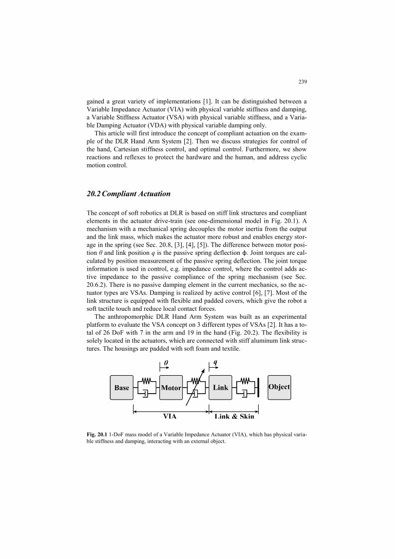
The concept of soft robotics at DLR is based on stiff link structures and compliant
elements in the actuator drive-train (see one-dimensional model in Fig. 20.1). A
mechanism with a mechanical spring decouples the motor inertia from the output
and the link mass, which makes the actuator more robust and enables energy stor-
age in the spring (see Sec. 20.8, [3], [4], [5]). The difference between motor posi-
tion θ and link position q is the passive spring deflection φ. Joint torques are cal-
culated by position measurement of the passive spring deflection. The joint torque
information is used in control, e.g. impedance control, where the control adds ac-
tive impedance to the passive compliance of the spring mechanism (see Sec.
20.6.2). There is no passive damping element in the current mechanics, so the ac-
tuator types are VSAs. Damping is realized by active control [6], [7]. Most of the
link structure is equipped with flexible and padded covers, which give the robot a
soft tactile touch and reduce local contact forces.
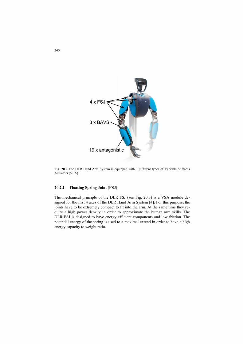
The anthropomorphic DLR Hand Arm System was built as an experimental
platform to evaluate the VSA concept on 3 different types of VSAs [2]. It has a to-
tal of 26 DoF with 7 in the arm and 19 in the hand (Fig. 20.2). The flexibility is
solely located in the actuators, which are connected with stiff aluminum link struc-
tures. The housings are padded with soft foam and textile.
Fig. 20.1 1-DoF mass model of a Variable Impedance Actuator (VIA), which has physical varia-
ble stiffness and damping, interacting with an external object.
240
Fig. 20.2 The DLR Hand Arm System is equipped with 3 different types of Variable Stiffness
Actuators (VSA).
20.2.1 Floating Spring Joint (FSJ)
The mechanical principle of the DLR FSJ (see Fig. 20.3) is a VSA module de-
signed for the first 4 axes of the DLR Hand Arm System [4]. For this purpose, the
joints have to be extremely compact to fit into the arm. At the same time they re-
quire a high power density in order to approximate the human arm skills. The
DLR FSJ is designed to have energy efficient components and low friction. The
potential energy of the spring is used to a maximal extend in order to have a high
energy capacity to weight ratio.

241
Fig. 20.3 Schematic of the DLR FSJ mechanism. [4]
The DLR FSJ has one big motor to change the output position of the actuator and
one small motor to change the stiffness preset of the spring mechanism. In this
setup only one motor has to move to change the link position of the robot. If the
small motor is kept in a fixed position, the actuator behaves like a Serial Elastic
Actuator (SEA). The nonlinear spring mechanism is in series between the main
gear and the output.
The torque is generated by a rotational cam disk and roller system which
transmits the rotational joint deflection to an axial compression of a linear spring.
The shape of the cam disks can be chosen according to the desired torque vs. dis-
placement behavior (see Fig. 20.4). For the DLR Hand Arm System the cam disk
shapes were chosen to have a good capability of stiffness variation under all load
conditions.
Fig. 20.4 The elastic torque characteristics of the DLR FSJ is parameterized by stiffness setup σ.
The stiffness setup is set by the small motor. [4]
242
20.2.2 Flexible Antagonistic Spring Element (FAS)
The FAS is motivated by the antagonistic arrangement of the human muscular sys-
tem. Herein, two muscles act in opposing directions to the joint. To change the
joint position, the muscles generate asymmetric forces. The stiffness can be varied
by co-contraction of the muscles, which generate internal forces. In order to
change the stiffness by co-contraction, the coupling between joint and muscles has
to be a non-linear spring, for which reason the tendons are exponential spring ele-
ments [8].
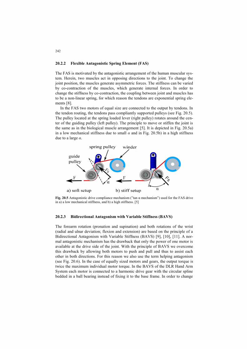
In the FAS two motors of equal size are connected to the output by tendons. In
the tendon routing, the tendons pass compliantly supported pulleys (see Fig. 20.5).
The pulley located at the spring loaded lever (right pulley) rotates around the cen-
ter of the guiding pulley (left pulley). The principle to move or stiffen the joint is
the same as in the biological muscle arrangement [5]. It is depicted in Fig. 20.5a)
in a low mechanical stiffness due to small α and in Fig. 20.5b) in a high stiffness
due to a large α.
Fig. 20.5 Antagonistic drive compliance mechanism (”tan α mechanism”) used for the FAS drive
in a) a low mechanical stiffness, and b) a high stiffness. [5]
20.2.3 Bidirectional Antagonism with Variable Stiffness (BAVS)
The forearm rotation (pronation and supination) and both rotations of the wrist
(radial and ulnar deviation; flexion and extension) are based on the principle of a
Bidirectional Antagonism with Variable Stiffness (BAVS) [9], [10], [11]. A nor-
mal antagonistic mechanism has the drawback that only the power of one motor is
available at the drive side of the joint. With the principle of BAVS we overcome
this drawback by allowing both motors to push and pull and thus to assist each
other in both directions. For this reason we also use the term helping antagonism
(see Fig. 20.6). In the case of equally sized motors and gears, the output torque is
twice the maximum individual motor torque. In the BAVS of the DLR Hand Arm
System each motor is connected to a harmonic drive gear with the circular spline
bedded in a ball bearing instead of fixing it to the base frame. In order to change
243
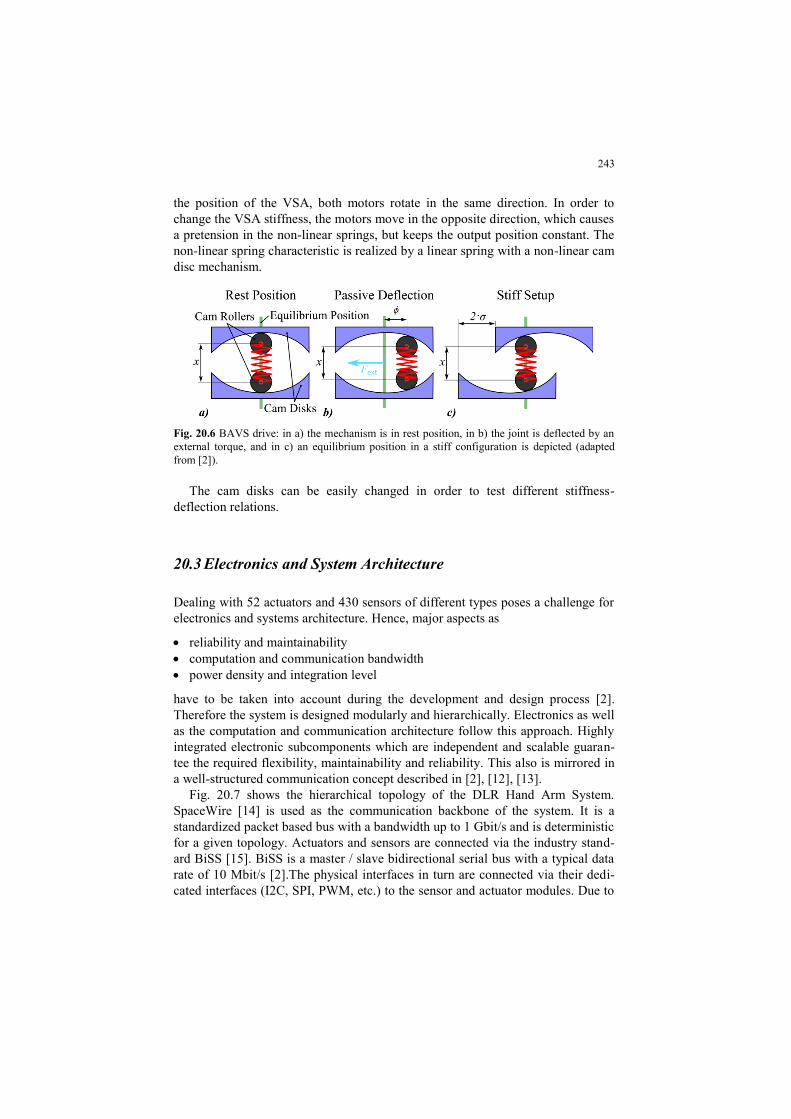
the position of the VSA, both motors rotate in the same direction. In order to
change the VSA stiffness, the motors move in the opposite direction, which causes
a pretension in the non-linear springs, but keeps the output position constant. The
non-linear spring characteristic is realized by a linear spring with a non-linear cam
disc mechanism.
Fig. 20.6 BAVS drive: in a) the mechanism is in rest position, in b) the joint is deflected by an
external torque, and in c) an equilibrium position in a stiff configuration is depicted (adapted
from [2]).
The cam disks can be easily changed in order to test different stiffness-
deflection relations.
20.3 Electronics and System Architecture
Dealing with 52 actuators and 430 sensors of different types poses a challenge for
electronics and systems architecture. Hence, major aspects as
reliability and maintainability
computation and communication bandwidth
power density and integration level
have to be taken into account during the development and design process [2].
Therefore the system is designed modularly and hierarchically. Electronics as well
as the computation and communication architecture follow this approach. Highly
integrated electronic subcomponents which are independent and scalable guaran-
tee the required flexibility, maintainability and reliability. This also is mirrored in
a well-structured communication concept described in [2], [12], [13].
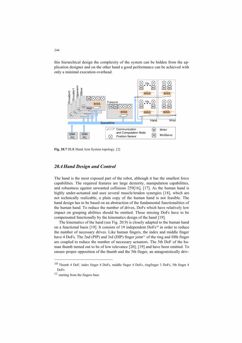
Fig. 20.7 shows the hierarchical topology of the DLR Hand Arm System.
SpaceWire [14] is used as the communication backbone of the system. It is a
standardized packet based bus with a bandwidth up to 1 Gbit/s and is deterministic
for a given topology. Actuators and sensors are connected via the industry stand-
ard BiSS [15]. BiSS is a master / slave bidirectional serial bus with a typical data
rate of 10 Mbit/s [2].The physical interfaces in turn are connected via their dedi-
cated interfaces (I2C, SPI, PWM, etc.) to the sensor and actuator modules. Due to
244
this hierarchical design the complexity of the system can be hidden from the ap-
plication designer and on the other hand a good performance can be achieved with
only a minimal execution overhead.
Fig. 20.7 DLR Hand Arm System topology. [2]
20.4 Hand Design and Control
The hand is the most exposed part of the robot, although it has the smallest force
capabilities. The required features are large dexterity, manipulation capabilities,
and robustness against unwanted collisions 259[16], [17]. As the human hand is
highly under-actuated and uses several muscle/tendon synergies [18], which are
not technically realizable, a plain copy of the human hand is not feasible. The
hand design has to be based on an abstraction of the fundamental functionalities of
the human hand. To reduce the number of drives, DoFs which have relatively low
impact on grasping abilities should be omitted. These missing DoFs have to be
compensated functionally by the kinematics design of the hand [19].
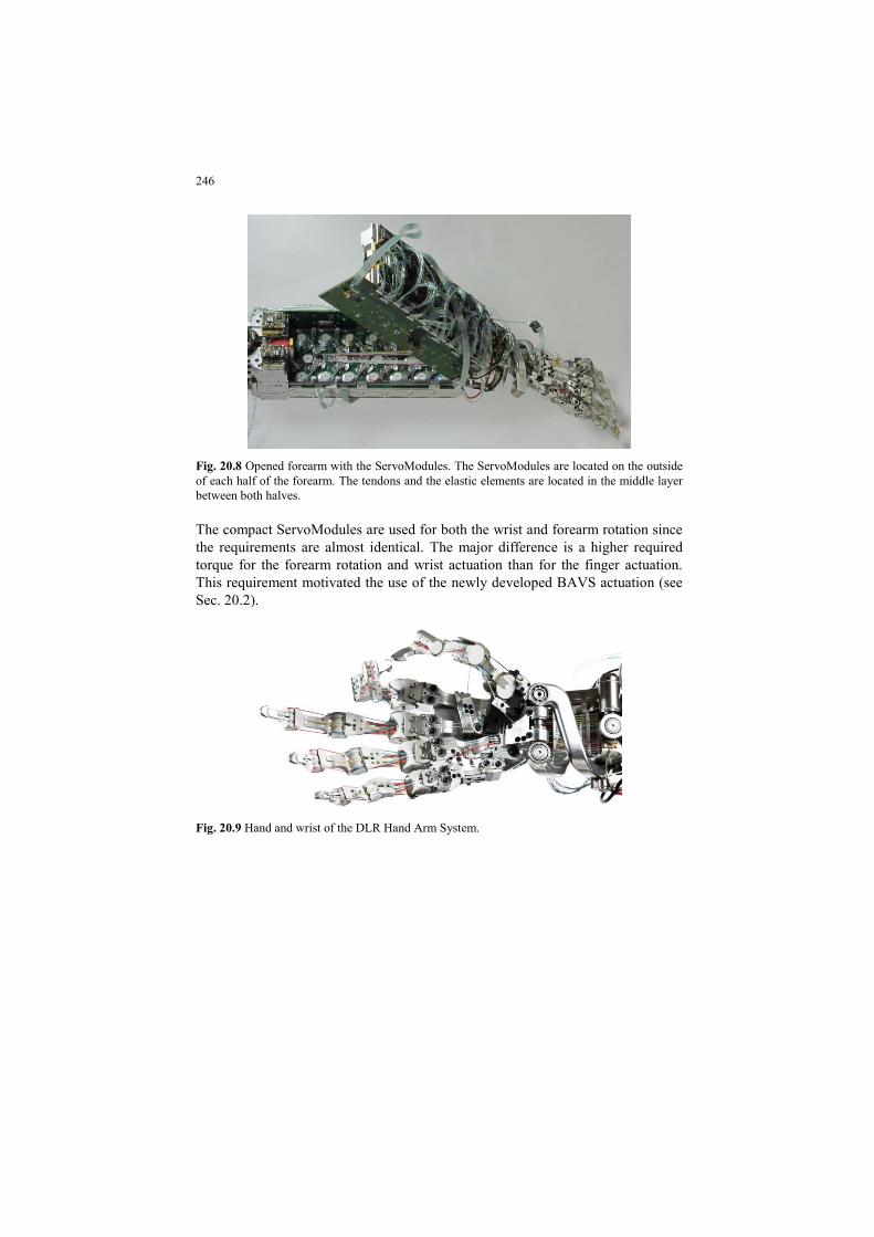
The kinematics of the hand (see Fig. 20.9) is closely adapted to the human hand
on a functional basis [19]. It consists of 19 independent DoFs10 in order to reduce
the number of necessary drives. Like human fingers, the index and middle finger
have 4 DoFs. The 2nd (PIP) and 3rd (DIP) finger joint11 of the ring and fifth finger
are coupled to reduce the number of necessary actuators. The 5th DoF of the hu-
man thumb turned out to be of low relevance [20], [19] and have been omitted. To
ensure proper opposition of the thumb and the 5th finger, an antagonistically driv-
10 Thumb 4 DoF, index finger 4 DoFs, middle finger 4 DoFs, ringfinger 3 DoFs, 5th finger 4
DoFs
11 starting from the fingers base
245
en 4 bar mechanism was designed to mimic the motion of the 5th finger metacar-
pal bone12. The structure of the finger is designed as an endoskeleton with “bionic
joints” [21]. The finger base (metacarpal) joint is a hyperbolically shaped saddle
joint because the human condyloid joint type cannot be replicated technically13.
The finger (interphalangeal) joints, on the other hand, are designed as hinge joints.
All joints allow dislocation without damage in case of overload14. In addition to
robustness due to short-term energy storage, the use of antagonistic actuation (see
Sec. 20.2) enables to cope with tendon slackening or overstretching, which is one
of the major problems of nowadays tendon-driven hands having inevitably con-
stant tendon length. In contrast, antagonistic actuation is able to compensate una-
ligned pulley axes, and other geometrical errors via the elastic elements of the
drive train. Therefore no explicit tendon tensioner is needed [22].
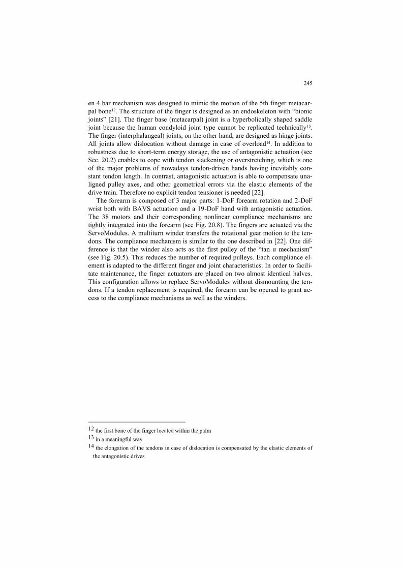
The forearm is composed of 3 major parts: 1-DoF forearm rotation and 2-DoF
wrist both with BAVS actuation and a 19-DoF hand with antagonistic actuation.
The 38 motors and their corresponding nonlinear compliance mechanisms are
tightly integrated into the forearm (see Fig. 20.8). The fingers are actuated via the
ServoModules. A multiturn winder transfers the rotational gear motion to the ten-
dons. The compliance mechanism is similar to the one described in [22]. One dif-
ference is that the winder also acts as the first pulley of the “tan α mechanism”
(see Fig. 20.5). This reduces the number of required pulleys. Each compliance el-
ement is adapted to the different finger and joint characteristics. In order to facili-
tate maintenance, the finger actuators are placed on two almost identical halves.
This configuration allows to replace ServoModules without dismounting the ten-
dons. If a tendon replacement is required, the forearm can be opened to grant ac-
cess to the compliance mechanisms as well as the winders.
12 the first bone of the finger located within the palm
13 in a meaningful way
14 the elongation of the tendons in case of dislocation is compensated by the elastic elements of
the antagonistic drives
246
Fig. 20.8 Opened forearm with the ServoModules. The ServoModules are located on the outside
of each half of the forearm. The tendons and the elastic elements are located in the middle layer
between both halves.
The compact ServoModules are used for both the wrist and forearm rotation since
the requirements are almost identical. The major difference is a higher required
torque for the forearm rotation and wrist actuation than for the finger actuation.
This requirement motivated the use of the newly developed BAVS actuation (see
Sec. 20.2).
Fig. 20.9 Hand and wrist of the DLR Hand Arm System.
247
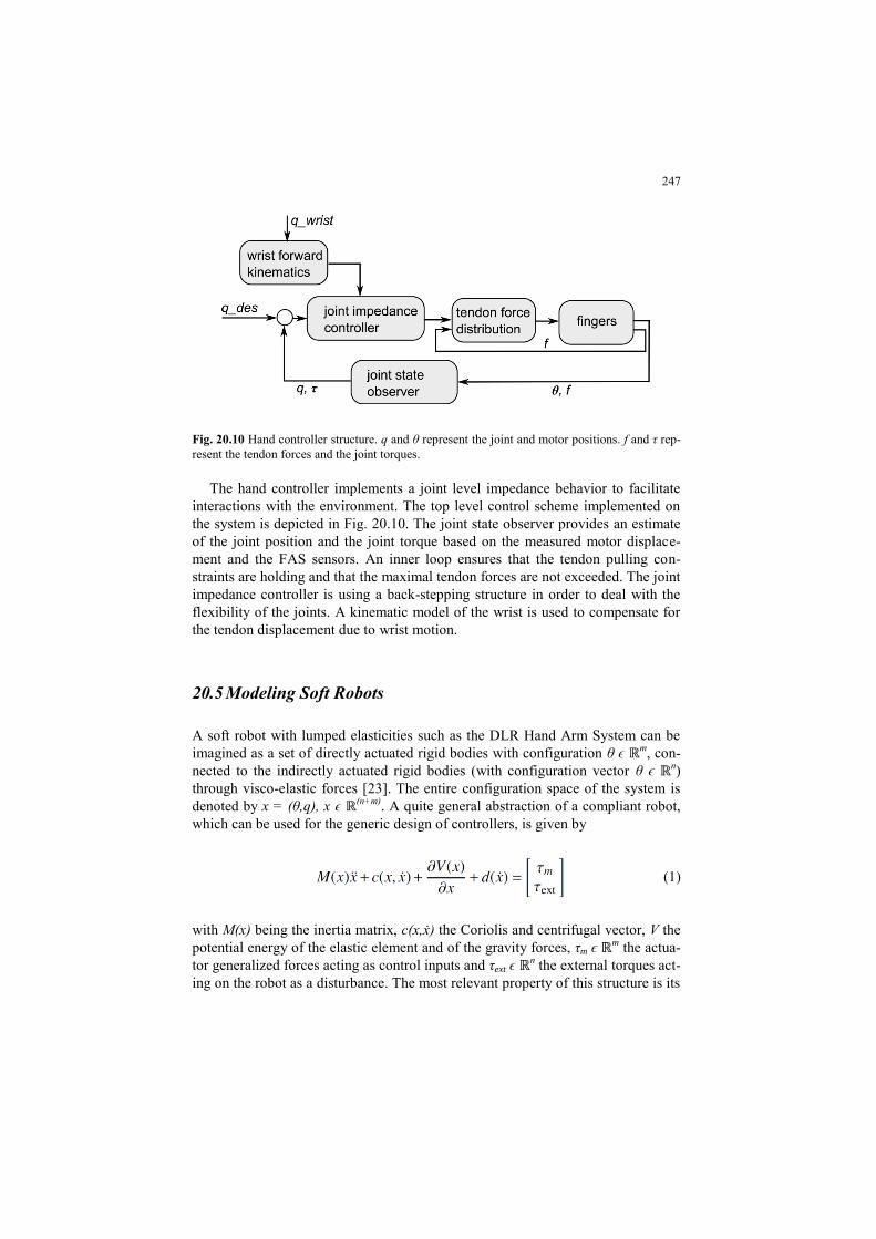
Fig. 20.10 Hand controller structure. q and θ represent the joint and motor positions. f and τ rep-
resent the tendon forces and the joint torques.
The hand controller implements a joint level impedance behavior to facilitate
interactions with the environment. The top level control scheme implemented on
the system is depicted in Fig. 20.10. The joint state observer provides an estimate
of the joint position and the joint torque based on the measured motor displace-
ment and the FAS sensors. An inner loop ensures that the tendon pulling con-
straints are holding and that the maximal tendon forces are not exceeded. The joint
impedance controller is using a back-stepping structure in order to deal with the
flexibility of the joints. A kinematic model of the wrist is used to compensate for
the tendon displacement due to wrist motion.
20.5 Modeling Soft Robots
A soft robot with lumped elasticities such as the DLR Hand Arm System can be
imagined as a set of directly actuated rigid bodies with configuration θ ϵ m, con-
nected to the indirectly actuated rigid bodies (with configuration vector θ ϵ n)
through visco-elastic forces [23]. The entire configuration space of the system is
denoted by x = (θ,q), x ϵ (n+m). A quite general abstraction of a compliant robot,
which can be used for the generic design of controllers, is given by
(1)
with M(x) being the inertia matrix, c(x,ẋ) the Coriolis and centrifugal vector, V the
potential energy of the elastic element and of the gravity forces, τm ϵ m the actua-
tor generalized forces acting as control inputs and τext ϵ n the external torques act-
ing on the robot as a disturbance. The most relevant property of this structure is its
248
under-actuation, meaning that the system has less control inputs (m) than its con-
figuration space dimension (n+m). However, in contrast to other purely inertially
coupled under-actuated systems15, for the considered robots V(x) is [24] positive
definite, implying that a unique equilibrium point exists for each external torque
with actuators in a fixed configuration θ = θ0 and that the linearization of the sys-
tem around an equilibrium point {x = x0; ẋ = 0} is controllable. Typically, V(x) =
VG (x) + Vτ (x), i.e. the potential function is the sum of a gravity potential VG and
an elastic potential Vτ. The elastic potential function Vτ (x) is a convex function,
increasing strongly enough to compensate for the destabilizing effects of VG, such
that V(x) is convex as well. Furthermore, the system contains in general a dissipa-
tive friction force d(ẋ) with ẋTd(ẋ) ≤ 0.
If there is no substantial inertial coupling between motors and links and under
some further mild simplification assumptions, the model can be written in a form
resembling more the classical flexible joint robots:
(2)
20.6 Cartesian Stiffness Control
20.6.1 Cartesian Impedance Control
While the mechanical stiffness of VIA robots can be adjusted in a wide range, not
any task impedance can be realized by shaping the intrinsic mechanical properties.
This is due to intrinsic limitation in minimal and maximal mechanical stiffness as
well due to the fact that so far, most robots do not have coupled stiffness elements
which would require multi-joint actuators [25]. This is in contrast to biological
systems, which have a much larger number of muscles and also contain a large
number of multi-articular joints. However, one can design a stiffness controller on
motor side, which acts in serial interconnection with the intrinsic mechanical stiff-
ness. Following a central paradigm of VIA, the mechanical robot parameters need
to be tuned such that the desired behavior is naturally achieved on a mechanism
level to the largest extent possible.
The stiffness behavior is described by a constant stiffness matrix KC =
ϵ
mxm as the relation between the Cartesian wrench f and the Cartesian displace-
ment x. The n passive and adjustable joint stiffness components provide the diag-
15 as for example multiple pendulums such as the Acrobot [27]
249
onal16 matrix KJ =
ϵ nxn
with the joint torques τ and the joint positions q. The
mapping from the Cartesian stiffness space to the joint stiffness space is given by
τ : KJ = T(KC).
This transformation can be written as
(3)
J(q) = ( )
is the manipulator Jacobian, where (q) is the forward kinematics
mapping. ∆x = xd - x is the Cartesian position error between the desired and the
actual position. The first part of (3) reflects the stiffness around the equilibrium
point. The second part of (3) is due to the change of the Jacobian, see [26].
The Cartesian stiffness a the equilibrium position (∆x = 0), resulting from a
specific joint stiffness can be obtained by solving the inverse problem of (3),
KC = τ -1
(KJ )17. Using compliance matrices C• = K•
-1, it results from
(4)
that
(5)
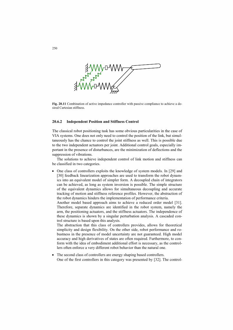
Active control adapts the stiffness in a wider range, and the elastic elements are
capable of absorbing impacts and increase the energy efficiency. By combining
the two concepts, one can benefit from the individual advantages. The serial inter-
connection of the active stiffness Kactive and the passive one Kpassive results in an
overall stiffness Kres (see Fig. 20.11):
(6)
To compute the active and passive stiffness components, a two-step optimization
algorithm can be used [28]. It achieves first a passive stiffness as close as possible
to the desired one and secondly designs the active stiffness to minimize the resid-
ual.
16 Decoupled joint compliance is assumed.
17 Note that at the equilibrium position the second term in 3 vanishes
250
Fig. 20.11 Combination of active impedance controller with passive compliance to achieve a de-
sired Cartesian stiffness.
20.6.2 Independent Position and Stiffness Control
The classical robot positioning task has some obvious particularities in the case of
VIA systems. One does not only need to control the position of the link, but simul-
taneously has the chance to control the joint stiffness as well. This is possible due
to the two independent actuators per joint. Additional control goals, especially im-
portant in the presence of disturbances, are the minimization of deflections and the
suppression of vibrations.
The solutions to achieve independent control of link motion and stiffness can
be classified in two categories.
One class of controllers exploits the knowledge of system models. In [29] and
[30] feedback linearization approaches are used to transform the robot dynam-
ics into an equivalent model of simpler form. A decoupled chain of integrators
can be achieved, as long as system inversion is possible. The simple structure
of the equivalent dynamics allows for simultaneous decoupling and accurate
tracking of motion and stiffness reference profiles. However, the abstraction of
the robot dynamics hinders the implementation of performance criteria.
Another model based approach aims to achieve a reduced order model [31].
Therefore, separate dynamics are identified in the robot system, namely the
arm, the positioning actuators, and the stiffness actuators. The independence of
these dynamics is shown by a singular perturbation analysis. A cascaded con-
trol structure is based upon this analysis.
The abstraction that this class of controllers provides, allows for theoretical
simplicity and design flexibility. On the other side, robot performance and ro-
bustness in the presence of model uncertainty are not guaranteed. High model
accuracy and high derivatives of states are often required. Furthermore, to con-
form with the idea of embodiment additional effort is necessary, as the control-
lers often enforce a very different robot behavior than the natural one.
The second class of controllers are energy shaping based controllers.
One of the first controllers in this category was presented by [32]. The control-
251
ler acts on motor position and uses a transformation to independently control
the joint position and stiffness. The controller is validated on a 1 DoF VSA
joint.
An extension and generalization has been presented in [33]. The control design
formulation is valid for a quite general form of underactuated Euler-Lagrange
systems including variable impedance robots. Herein, the controller action can
be interpreted as shaping of the potential and kinetic robot energy ensuring sys-
tem passivity.
A general task is described as to control k independent output variables given
by q = h(x) to desired constant values qd ϵ Rk. ϵ R
n is the vector of generalized
coordinates, where n = 2k is the usual case for VSA robots. Given the structure
of VSA robots (2), a new variable q̄ can be found. This is a collocated (directly
actuated) variable, which is statically equivalent to the noncollocated (indirect-
ly actuated) q. Using this collocated variable for a passive feedback ensures
stability and can be interpreted as shaping the potential energy of the system.
The variable q̄ is achieved by solving the static solution of the link side equation
(7)
for q. Except for very simple cases, this equation has to be solved numerically.
Due to the convex nature, this is a fast and numerically robust task in practice.
Consequently, the controller
(8)
is stabilizing the desired position qd.g( q̄ ) is a feed forward term, compensating
for the gravity. The use of q̄ enables arbitrarily low controller gains even for large
displacements from the equilibrium. Jq̄ is a Jacobian mapping the collocated vari-
able on the statically equivalent q̄. Global asymptotic stability based on La Salle’s
invariance theorem can be shown.
The approach can be extended in order to include also feedback of torque and
torque derivative, with the effect of reducing the apparent actuator inertia and fric-
tion. This allows improving the transient performance while remaining within the
passivity framework.
The energy shaping approach provides excellent performance in the static case
and for well damped systems. However, some joints show low intrinsic damping
to enable joint torque estimation and energy efficiency. In this case it is desirable
to add additional damping via control or to include a physical variable damping
element. Several damping control structures can be considered. A simple gain
scheduling approach for a one DoF system has been presented in [34]. Local linear
sub-problems are identified on which a LQR state feedback controller is designed.
The nonlinearity of the robot dynamics requires adapting the controller poles de-
pendent on the system state, which is especially hard for the multi joint robots.
252
A physically motivated state feedback control approach for multi-DoF VSA
robots has been presented in [6] using an eigenvalue based modal decomposition.
20.7 Optimal Control
Humans are capable of highly dynamic motions such as throwing or kicking. A
major feature that presumably enables them to perform such tasks is their ability
to optimally store and release elastic energy in the compliant elements of the mus-
culoskeletal system, in combination with inertial energy transfer between the rigid
parts of the body. Based on this feature, using elastic elements in robot joints, and
finding control strategies which exploit this elasticity optimally has recently drawn
significant attention.
The question of how to make use of the (adjustable) potential energy stored in
elastic elements of a robotic system in the best possible way is not a trivial one,
especially when considering the increased complexity of robotic systems with ad-
ditional elasticity. A powerful mathematical tool for dealing with this question is
Optimal Control (OC) Theory [35], which provides conditions for the control to
minimize a given cost functional. Generally, a cost functional can be written as a
sum of two terms
(9)
where the first term, the terminal cost, considers the final state of the state and the
terminal time, whereas the second term, the integral cost, takes the whole trajecto-
ry into account. By choosing an appropriate cost functional, the optimal cost can
then be used as an indicator for the performance one can gain from elastic joints.
Unfortunately, the conditions which OC theory provides, cannot always directly
be formulated as control laws, especially when one wants to analyse a complex
robotic system with multiple degrees of freedom and various nonlinearities. Nev-
ertheless, under some simplifying assumptions, it is in some cases also possible to
find analytical solutions, which are useful in understanding the best control strate-
gies for these novel devices. Consequently, two main approaches are being fol-
lowed for the analysis of these systems.
The first one is to work on simplified models such that analytical results can be
obtained ([36][37][38][39][40][41][42][43][44][45]). These results are useful to
reveal the relation between the system’s parameters such as eigenfrequency,
damping ratio and the maximum attainable performance regarding for instance the
system’s peak velocity during a throwing motion. The second approach is the use
of powerful numerical tools such as pseudospectral methods [46], which have
been successfully applied to various robotic systems including the DLR Hand
Arm System ([37], [2], [48], [49]).
253
Even though one can compute the optimal control strategy for complicated sys-
tems following the second approach, this computation may require a significant
amount of time depending on the complexity of the used model. Consequently, for
applications where the optimal control strategy is needed in real-time, these meth-
ods need to be further developed. In [50], the problem of generating optimal mo-
tions in real-time was addressed by encoding trajectories via Dynamic Movement
Primitives (DMPs). The optimal trajectories learned via DMPs have the advantage
of being reconstructable in real-time with high precision. Furthermore, the extrap-
olation to other tasks show near-optimal behavior, which has been illustrated in
[50] by realizing a ball throwing motion with the DLR Hand Arm System, when
the goal position is varying.
Comparing the existing results regarding the optimal control of elastic joints in
literature, a lack of existing analytical results especially for n-DoF systems is ap-
parent. Consequently, filling this gap and combining the gained insight for more
efficient numerical methods and learning algorithms is an ongoing research.
20.8 Collision Detection and Reaction
As mentioned previously, intrinsic joint elasticity improves impact robustness.
In addition, the potential energy storage and release capabilities in the joints allow
to outperform rigid manipulators by means of achievable peak link velocity. While
high link velocities are desirable in terms of performance, they may also increase
the robot’s level of dangerousness and the risk of self-damage during collisions. In
other words we have to consider both, threats for the environment and the robot.
Threats for the environment are mainly caused by contact forces with the robot,
whereas threats for the robot are dominated by the torque in the drive-train of the
robot actuators. Thus, the problem of ensuring safety has to be treated differentiat-
ed. In physical human-robot interaction (pHRI) it is therefore important to detect
contact with the environment and take appropriate countermeasures by control in
case of unwanted collisions.
For detecting and isolating collisions with the DLR Hand Arm System, we use
the generalized link momentum observer proposed in [51]. As this observer re-
quires knowledge of the elastic joint torque, we use an estimate obtained by model
identification. An alternative scheme described in [30] observes both the motor
and link momentum and therefore does require identification of the joint torque.
However, this scheme showed poor performance in practice because it is sensitive
to unmodeled motor friction. Having detected collisions with the environment,
collision reaction schemes can be activated to ensure the physical integrity of hu-
man and robot.
254
20.8.1 Reactions
The most intuitive collision reaction is to stop the robot. For rigid robots or robots
with high joint stiffness such as the LWR-III, stopping can simply be achieved by
engaging the brakes or commanding the current position to the position controller.
However, when halting the motors of VSA robots the links can still oscillate sig-
nificantly due to the intrinsic joint elasticity. This can result in large link side ve-
locities and even constraints such as maximum elastic deflection may be violated.
The decrease of link velocity then depends on the damping of the joints, which is
typically undesired for VSA robots and therefore very low.
Braking of elastic joint robots can be achieved by introducing active damping
by control. For this, several schemes have been proposed recently. The state feed-
back controller described in [6] bases on a eigenmode decoupling approach and
selects feedback gains such that dynamics and control behave like damped second
order systems. A second decoupling based method described in [52] aims at brak-
ing an elastic robot as fast as possible, in other words, introducing as much damp-
ing as possible. The controller makes use of optimal control theory to brake each
decoupled SISO mass-spring system in minimum time. It is noteworthy, that this
optimal control problem can be solved in real-time. Both previously mentioned
methods require a dynamic model of the robot. A model-free approach was pre-
sented in [7] were the energy storage and release process of every joint is exploit-
ed to form a passive damping controller.
An overload in the drive-train of a VSA robot typically results in the situation
that the spring deflection limit is approached, e.g. by an external impact. In this
case the mechanics or spring is likely damaged. In order to avoid this, an extreme-
ly large spring could be utilized, which would be of no use during the normal op-
erations and would increase weight and bulkiness. An alternative is to actively
move the VSA position in the direction of the threatening torque, so that the
spring is discharged. This for example can be initiated at a load level above a giv-
en remaining potential energy capacity, or a remaining passive deflection angle
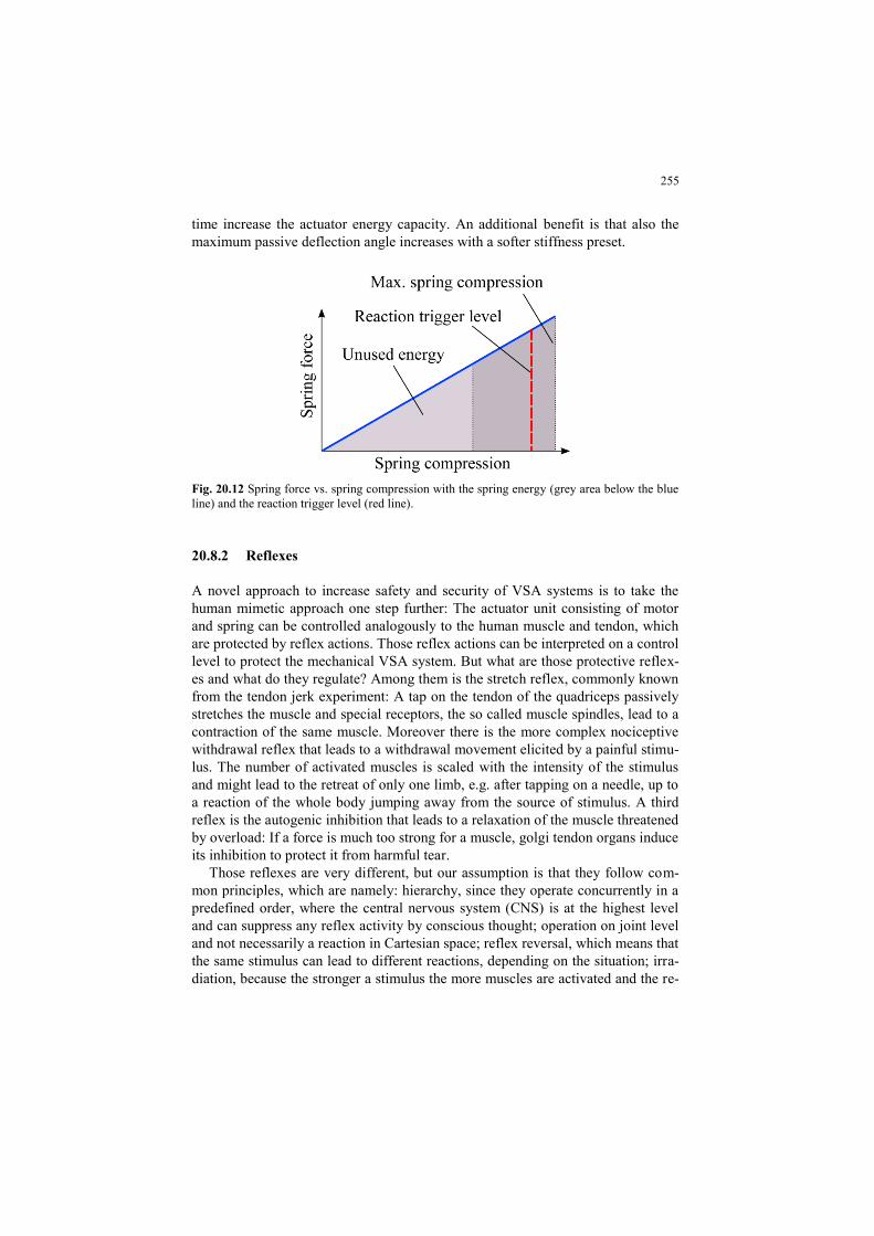
(see red dashed line in Fig. 20.12), [53].
Another possible reaction to avoid spring overload takes advantage of the ca-
pability of a VSA to change its stiffness. It uses the same activation criteria as the
previous reaction. Depending on the construction and the implementation princi-
ple, a VSA features different spring energy capacity or maximum deflection angle
at different stiffness presents. If the VSA is set due to application demands to a
less advantageous stiffness preset concerning the robustness issue, this can be mit-
igated by the reaction strategy. As long as the threat of overload is present the
VSA changes the stiffness preset to a safer state and returns to the normal state
when the critical situation is over. Spring preload type and antagonistic VSAs
have a higher energy capacity at lower stiffness presets, because the energy used
to preload the spring(s) for a stiffer setup cannot be used for passive deflection
(light grey area in Fig. 20.12). In this case the motors release the preload during
the reaction so that they do not have to supply additional power and at the same
255
time increase the actuator energy capacity. An additional benefit is that also the
maximum passive deflection angle increases with a softer stiffness preset.
Fig. 20.12 Spring force vs. spring compression with the spring energy (grey area below the blue
line) and the reaction trigger level (red line).
20.8.2 Reflexes
A novel approach to increase safety and security of VSA systems is to take the
human mimetic approach one step further: The actuator unit consisting of motor
and spring can be controlled analogously to the human muscle and tendon, which
are protected by reflex actions. Those reflex actions can be interpreted on a control
level to protect the mechanical VSA system. But what are those protective reflex-
es and what do they regulate? Among them is the stretch reflex, commonly known
from the tendon jerk experiment: A tap on the tendon of the quadriceps passively
stretches the muscle and special receptors, the so called muscle spindles, lead to a
contraction of the same muscle. Moreover there is the more complex nociceptive
withdrawal reflex that leads to a withdrawal movement elicited by a painful stimu-
lus. The number of activated muscles is scaled with the intensity of the stimulus
and might lead to the retreat of only one limb, e.g. after tapping on a needle, up to
a reaction of the whole body jumping away from the source of stimulus. A third
reflex is the autogenic inhibition that leads to a relaxation of the muscle threatened
by overload: If a force is much too strong for a muscle, golgi tendon organs induce
its inhibition to protect it from harmful tear.
Those reflexes are very different, but our assumption is that they follow com-
mon principles, which are namely: hierarchy, since they operate concurrently in a
predefined order, where the central nervous system (CNS) is at the highest level
and can suppress any reflex activity by conscious thought; operation on joint level
and not necessarily a reaction in Cartesian space; reflex reversal, which means that
the same stimulus can lead to different reactions, depending on the situation; irra-
diation, because the stronger a stimulus the more muscles are activated and the re-
256
action is spread (irradiated) over the joints; the preservation of a status quo, which
is e.g. stability or sanity. The reflexes, interpreted on a control level, are a combi-
nation of PD control (stretch reflex), force/torque control (autogenic inhibition)
and a fast trajectory (nociceptive withdrawal reflex).We propose an activation
strategy of the reflexes based on two inputs: The measured deflection of the spring
mechanism, directly correlating to the torque, since the stiffness of the spring is
known, and the force input from an artificial skin. The activation is complemented
with a switching strategy of the control mode that preserves the stability of the
system in action. Thus, the system is PD controlled and moves away from a source
of stimulus to the artificial skin that is arranged in so called reflex responsive
fields, eliciting a movement of the proximal joint away from the source of stimu-
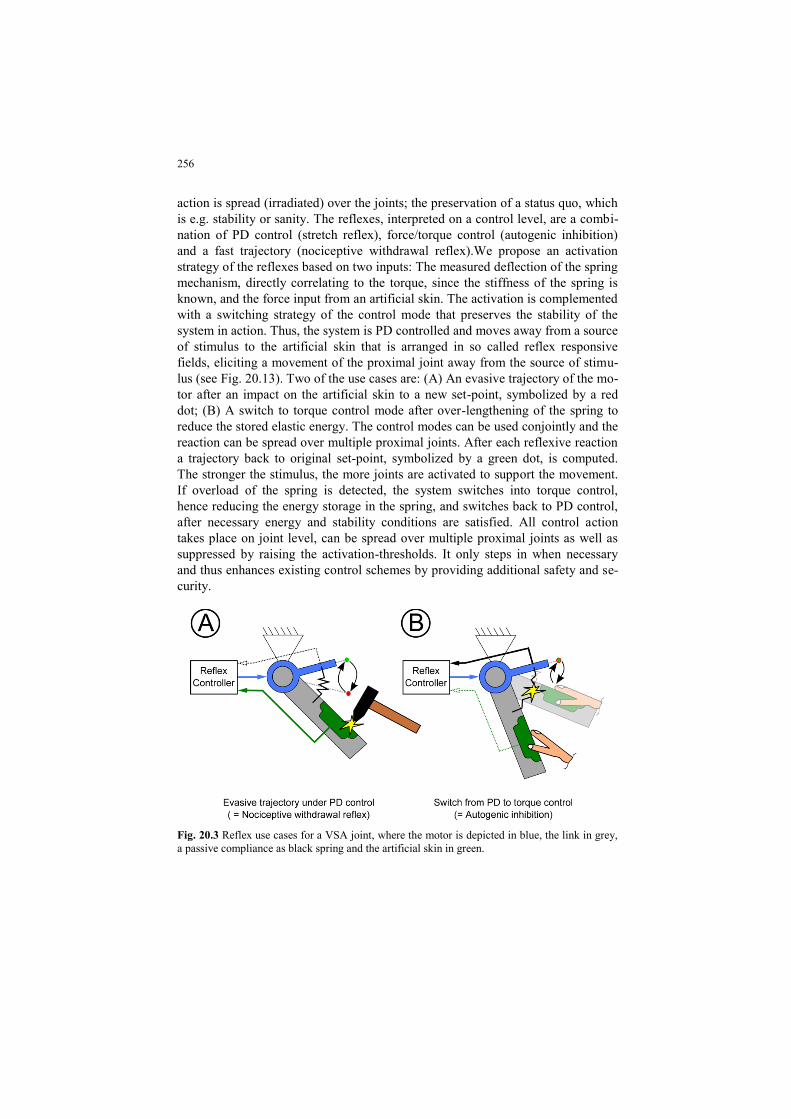
lus (see Fig. 20.13). Two of the use cases are: (A) An evasive trajectory of the mo-
tor after an impact on the artificial skin to a new set-point, symbolized by a red
dot; (B) A switch to torque control mode after over-lengthening of the spring to
reduce the stored elastic energy. The control modes can be used conjointly and the
reaction can be spread over multiple proximal joints. After each reflexive reaction
a trajectory back to original set-point, symbolized by a green dot, is computed.
The stronger the stimulus, the more joints are activated to support the movement.
If overload of the spring is detected, the system switches into torque control,
hence reducing the energy storage in the spring, and switches back to PD control,
after necessary energy and stability conditions are satisfied. All control action
takes place on joint level, can be spread over multiple proximal joints as well as
suppressed by raising the activation-thresholds. It only steps in when necessary
and thus enhances existing control schemes by providing additional safety and se-
curity.
Fig. 20.3 Reflex use cases for a VSA joint, where the motor is depicted in blue, the link in grey,
a passive compliance as black spring and the artificial skin in green.
257
20.9 Cyclic Motion Control
Key properties of compliant actuators in robotic arms are the capability to improve
performance and energetic efficiency. Especially in case of cyclic motion tasks,
the capability to buffer and release elastic energy may reduce the size and weight
of required actuators and save a substantial amount of energy. These properties are
even of increased importance for legged robots, which need to wirelessly walk,
jump, or run over rough and uneven terrain. The step from rigid towards elastic
actuation introduces natural oscillation dynamics into the plant. In our recent
works [54], [55], [56], [57], [58], [58], novel concepts to exploit these natural dy-
namics have been derived.
Considered limit cycle control methods range from classical principles based
on the well-known Van der Pol oscillator to novel concepts following the idea of
resonance and natural dynamics excitation. The former method is adapted from
rigid actuator control, where the generalized force of the second-order dynamics
can be considered as control input. An implementation for compliant actuators is
proposed in [54]. The latter method is derived from human motor control [56],
[58]. This method directly applies to continuous second-order systems18 of the
form
with positive plant parameters19 representing a large class of compliantly actuated
robotic joints. The limit cycle controller is simply the switching law20.
For the maximally efficient controller parameters ̂ ≤ 2ϵ, this controller generates
a globally asymptotically stable limit cycle without any model knowledge, only
based upon measurements of the spring deflection [58].
The extension of the above methods from the single to the multiple joint case
under the concept of natural dynamics exploitation is derived from the notion of
intrinsic mechanical oscillation modes [58]. Exploiting the idea of two dimension-
al invariant submanifolds, 2nth
-order dynamics of multiple joint robots collapses to
second-order dynamics of a single joint. This dimensionality reduction can be
achieved using one of the following approaches:
18 The system has continuous states ̇ ∈
19 The inertia m > 0, the generalized damping force is positive semi-definite in a sense that d(q,q
) q 0 and the elastic potential U(ϕ) is positive definite w.r.t. the spring deflection ϕ. 20 The finite dynamics is piecewise continuous from the left, i.e. θ represents the state of θ be-
fore the switching.
258
Considering a locally valid linearization of the nonlinear plant dynamics,
linear eigenmodes can be identified. The valid range of these modes can
be extended to hold globally by feedback control [54].
On the basis of the switching control, a directed excitation along an in-
trinsic mechanical oscillation mode can be achieved by adaptive control
[55].
A method to generate a limit cycle along a predefined oscillation mode
has been derived from classical impedance and null-space control [36].
The above methods can be nearly arbitrarily combined to achieve a multiple de-
gree of freedom limit cycle control. One can adapt to one of the following re-
quirements: task adaptability, performance, or efficiency.
20.10 Conclusion
We highlighted in this chapter that intrinsic flexibility in robotic systems is of cru-
cial importance to obtain human level power density and to interact safely with
humans and unknown environments. Using classical electro-mechanical actuation
in combination with nonlinear elastic joint mechanisms allows realizing high per-
formance actuators, with high motion repeatability and high efficiency. A large
amount of control literature on flexible joint robots can be therefore accessed and
adapted to the nonlinear, adjustable stiffness case. In this chapter we addressed on
the basis of the DLR Hand Arm System all major aspects related to the mecha-
tronic design and control of VSA robots. As a research prototype, the DLR Hand
Arm System fully validates the feasibility of the VSA concepts. A major draw-
back remains the relatively high complexity of the nonlinear elastic joint. New
technological approaches to implement the variable elastic element and integrated
electronics solutions would therefore support the evolution of VSA systems to-
wards commercial applications.
20.11 References
[1] Vanderborght B, Albu-Schäffer A, Bicchi A, Burdet E, Caldwell D, Carloni R, Catalano
M, Eiberger O, Friedl W, Ganesh G, Garabini M, Grebenstein M, Grioli G, Haddadin S,
Höppner H, Jafari A, Laffranchi M, Lefeber D, Petit F, Stramigioli S, Tsagarakis N,
Damme MV, Ham RV, Visser L, Wolf S (2013) Variable impedance actuators: A review.
Robotics and Autonomous Systems 61(12):1601–1614, DOI
http://dx.doi.org/10.1016/j.robot.2013.06.009
[2] Grebenstein M, Albu-Schäffer A, Bahls T, Chalon M, Eiberger O, Friedl W, Gruber R,
Haddadin S, Hagn U, Haslinger R, Höppner H, Jörg S, Nickl M, Nothhelfer A, Petit F,
Reill J, Seitz N, Wimböck T, Wolf S, Wüsthoff T, Hirzinger G (2011) The DLR Hand
259
Arm System. In: IEEE International Conference on Robotics and Automation (ICRA), pp
3175–3182, DOI 10.1109/ ICRA.2011.5980371
[3] Wolf S, Hirzinger G (2008) A new variable stiffness design: Matching requirements of
the next robot generation. In: Robotics and Automation, 2008. ICRA 2008. IEEE Interna-
tional Conference on, Pasadena, CA, USA, pp 1741–1746, DOI
10.1109/ROBOT.2008.4543452
[4] Wolf S, Eiberger O, Hirzinger G (2011) The DLR FSJ: Energy based design of a variable
stiffness joint. In: Robotics and Automation (ICRA), 2011 IEEE International Conference
on, pp 5082–5089, DOI 10.1109/ICRA.2011.5980303
[5] Friedl W, Chalon M, Reinecke J, Grebenstein M (2011) FAS A flexible antagonistic
spring element for a high performance over. In: Intelligent Robots and Systems (IROS),
2011 IEEE/RSJ International Conference on, pp 1366–1372, DOI
10.1109/IROS.2011.6094569
[6] Petit F, Albu-Schäffer A (2011) State feedback damping control for a multi dof variable
stiffness robot arm. In: IEEE Int. Conf. on Robotics and Automation (ICRA), IEEE, pp
5561–5567
[7] Petit F, Ott C, Albu-Schäffer A (2014) A model-free approach to vibration suppression
for intrinsically elastic robots. In: IEEE Int. Conf. on Robotics and Automation (ICRA),
IEEE
[8] Cui L, Maas H, Perreault EJ, Sandercock TG (2009) In situ estimation of tendon material
properties: Differences between muscles of the feline hindlimb. Journal of Biomechanics
42(6):679 – 685, DOI http://dx.doi.org/10.1016/j. jbiomech.2009.01.022
[9] Friedl W, Höppner H, Petit F, Hirzinger G (2011) Wrist and forearm rotation of the DLR
Hand Arm System: Mechanical design, shape analysis and experimental validation. In:
Intelligent Robots and Systems (IROS), 2011 IEEE/RSJ International Conference on, pp
1836–1842, DOI 10.1109/IROS. 2011.6094616
[10] Petit F, Chalon M, Friedl W, Grebenstein M, Albu-Schäffer A, Hirzinger G (2010) Bidi-
rectional antagonistic variable stiffness actuation: Analysis, design amp; implementation.
In: Robotics and Automation (ICRA), 2010 IEEE International Conference, pp 4189–
4196, DOI 10.1109/ROBOT.2010.5509267
[11] Petit F, Friedl W, Höppner H, Grebenstein M (2014) Analysis and synthesis of the bidi-
rectional antagonistic variable stiffness mechanism. Mechatronics, IEEE/ASME Transac-
tions on PP(99):1–12, DOI 10.1109/TMECH.2014. 2321428
[12] Jörg S, Nickl M, Nothhelfer A, Bahls T, Hirzinger G (2011) The computing and commu-
nication architecture of the DLR hand arm system. In: Proceedings IEEE/RSJ Interna-
tional Conference on Intelligent Robots and Systems, pp 1055–1062
[13] Nickl M, Jörg S, Bahls T, Nothhelfer A, Strasser S (2011) Spacewire, a backbone for
humanoid robotic systems. In: Proceedings of the 4th International SpaceWire Confer-
ence, pp 356–359
[14] European Cooperation for Space Standardization (ECSS) (2003) ECSS E-50-12A
SpaceWire - Links, nodes routers and networks. http://spacewire.eas.int
[15] IC Haus (2007) BiSS C Interface Protocol (C-Mode). http://www.ichaus.com, c1 edn
[16] Grebenstein M (2014) Approaching Human Performance: The Functionality-Driven
Awiwi Robot Hand (Springer Tracts in Advanced Robotics). Springer, Berlin; Heidel-
berg; New York
[17] Grebenstein M, Chalon M, Friedl W, Haddadin S, Wimböck T, Hirzinger G, Siegwart R
(2012) The hand of the DLR Hand Arm System: Designed for interaction. IJRR
31(13):1531–1555
[18] Gray H (1999) Anatomy, descriptive and surgical. Courage Books, Philadelphia
[19] Grebenstein M, Chalon M, Hirzinger G, Siegwart R (2010) A method for hand kinemat-
ics designers; 7 billion perfect hands. International Conference on Advances in Biosci-
ence and Bioengineering
260
[20] Chalon M, Grebenstein M, Wimböck T, Hirzinger G (2010) The thumb: Guidelines for a
robotic design. Intelligent Robots and Systems, (2010) IEEE/RSJ International Confer-
ence on, pp 2153–2858
[21] Grebenstein M, Chalon M, Hirzinger G, Siegwart R (2010) Antagonistically driven finger
design for the anthropomorphic DLR Hand Arm System. Humanoids Robots, IEEE/RAS
International Conference, pp 609–616
[22] Grebenstein M, van der Smagt P (2008) Antagonism for a highly anthropomorphic hand-
arm system. Advanced Robotics 1(22):39–55, DOI 10.1163/156855308X291836
[23] Albu-Schäffer A, Wolf S, Eiberger O, Haddadin S, Petit F, Chalon M (2010) Dynamic
modelling and control of variable stiffness actuators. In: Robotics and Automation
(ICRA), 2010 IEEE International Conference on, pp 2155 –2162, DOI
10.1109/ROBOT.2010.5509850
[24] Jafari A, Tsagarakis N, Caldwell D (2013) A novel intrinsically energy efficient devel-
opment of a novel actuator with adjustable stiffness (awas). IEEE Transactions on Mech-
atronics 18(1)
[25] Albu-Schäffer A, Fischer M, Schreiber G, Schoeppe F, Hirzinger G (2004) Soft robotics:
What cartesian stiffness can we obtain with passively compliant, uncoupled joints? In:
Proc. of the IEEE/RSJ Int. Conf. on Intelligent Robots and Systems, pp 3295–3301
[26] Hogan N (1990) Mechanical impedance of single- and multi-articular systems. In: Win-
ters J,Woo SY (eds) Multiple Muscle Systems, Springer New York, pp 149–164
[27] Fantoni I, Lozano R, Spong MW (2000) Energy based control of the pendubot. IEEE
Trans on Automatic Control 45(4):725–729
[28] Petit F, Albu-Schäffer A (2011) Cartesian impedance control for a variable stiffness robot
arm. In: Proc. of the IEEE/RSJ International Conference on Intelligent Robots and Sys-
tems, pp 4180–4186
[29] Palli G, Melchiorri C, Luca AD (2008) On the feedback linearization of robots with vari-
able joint stiffness. In: Proc. IEEE Int. Conf. on Robotics and Automation, pp 1753 –
1759
[30] De Luca A, Flacco F, Bicchi A, Schiavi R (2009) Nonlinear decoupled motion-stiffness
control and collision detection/reaction for the vsa-ii variable stiffness device. In:
IEEE/RSJ Int. Conf. on Intelligent Robots and Systems (IROS2009), IEEE, pp 5487–
5494
[31] Palli G, Melchiorri C (2011) Output-based control of robots with variable stiffness actua-
tion. Journal of Robotics
[32] Tonietti G, Schiavi R, Bicchi A (2005) Design and control of a variable stiffness actuator
for safe and fast physical human/robot interaction. In: Proc. IEEE Int. Conf. on Robotics
and Automation, pp 528–533
[33] Albu-Schäffer A, Ott C, Petit F (2012) Energy shaping control for a class of underactuat-
ed euler-lagrange systems. In: IFAC Symposium on Robot Control
[34] Sardellitti I, Medrano-Cerda G, Tsagarakis NG, Jafari A, Caldwell DG (2012) A position
and stiffness control strategy for variable stiffness actuators. In: Proc. IEEE Int. Conf. on
Robotics and Automation
[35] Pontryagin L (1987) Mathematical Theory of Optimal Processes. Classics of Soviet
Mathematics, Taylor & Francis
[36] Garabini M, Passaglia A, Belo FAW, Salaris P, Bicchi A (2011) Optimality principles in
variable stiffness control: the VSA hammer. 2011 IEEE/RSJ International Conference on
Intelligent Robots and Systems (IROS2011), San Francisco, USA pp 3770 – 3775
[37] Garabini M, Passaglia A, Belo F, Salaris P, Bicchi A (2012) Optimality principles in
stiffness control: The VSA kick. In: Robotics and Automation (ICRA), 2012 IEEE Inter-
national Conference on, pp 3341–3346
[38] Haddadin S, Weis M, Albu-Schäffer A, Wolf S (2011) Optimal control for maximizing
link velocity of robotic variable stiffness joints. In: Proceedings IFAC 2011, World Con-
gress pp 3175–3182
261
[39] Haddadin S, Krieger K, Mansfeld N, Albu-Schäffer A (2012) On impact decoupling
properties of elastic robots and time optimal velocity maximization on joint level. In: In-
telligent Robots and Systems (IROS), 2012 IEEE/RSJ International Conference, pp
5089–5096, DOI 10.1109/IROS.2012.6385913
[40] Haddadin S, Özparpucu M, Albu-Schäffer A (2012) Optimal control for maximizing po-
tential energy in a variable stiffness joint. In: Decision and Control (CDC), 2012 IEEE
51st Annual Conference, pp 1199–1206
[41] Incaini R, Sestini L, Garabini M, Catalano MG, Grioli G, Bicchi A (2013) Optimal con-
trol and design guidelines for soft jumping robots: Series elastic actuation and parallel
elastic actuation in comparison. In: IEEE International Conference on Robotics and Au-
tomation (ICRA2013), pp 2477 – 2484
[42] Özparpucu MC, Albu-Schäffer A (2014, Accepted) Optimal control strategies for maxim-
izing the performance of variable stiiffness joints with nonlinear springs. In: Decision and
Control (CDC), 2014 IEEE 53rd Annual Conference on
[43] Özparpucu MC, Haddadin S (2013) Optimal control for maximizing link velocity of vis-
co-elastic joints. In: Intelligent Robots and Systems (IROS), 2013 IEEE/RSJ International
Conference on, pp 3035–3042
[44] Özparpucu MC, Haddadin S (2014) Optimal control of elastic joints with variable damp-
ing. In: Control Conference (ECC), 2014 European, pp 2526–2533
[45] Özparpucu MC, Haddadin S, Albu-Schaffer A (2014, Accepted) Optimal control of vari-
able stiffness actuators with nonlinear springs. In: Proceedings. IFAC 2014, World Con-
gress
[46] Garg D, Patterson MA, Hager WW, Rao AV, Benson DA, Huntington GT (2010) A uni-
fied framework for the numerical solution of optimal control problems using pseudospec-
tral methods. Automatica 46(11):1843–1851
[47] Braun D, Howard M, Vijayakumar S (2011) Exploiting variable stiffness in explosive
movement tasks. In: Proceedings of Robotics: Science and Systems (RSS2011), Los An-
geles, USA, pp 25–32
[48] Haddadin S, Huber F, Albu-Schäffer A (2012) Optimal control for exploiting the natural
dynamics of variable stiffness robots. In: Robotics and Automation (ICRA), 2012 IEEE
International Conference, pp 3347–3354, DOI 10.1109/ICRA.2012.6225190
[49] Mettin U, Shiriaev A (2011) Ball-pitching challenge with an underactuated two-link ro-
bot arm. Proceedings IFAC 2011, World Congress pp 1–6
[50] Weitschat R, Haddadin S, Huber F, Albu-Schäffer A (2013) Dynamic optimality in real-
time: A learning framework for near-optimal robot motions. In: Intelligent Robots and
Systems (IROS), 2013 IEEE/RSJ International Conference on, pp 5636–5643
[51] De Luca A, Albu-Schäffer A, Haddadin S, Hirzinger G (2006) Collision detection and
safe reaction with the DLR-III lightweight manipulator arm. In: IEEE/RSJ Int. Conf. on
Intelligent Robots and Systems (IROS2006), IEEE, pp 1623–1630
[52] Mansfeld N, Haddadin S (2014) Reaching desired states time-optimally from equilibrium
and vice versa for visco-elastic joint robots with limited elastic deflection. In: IEEE/RSJ
Int. Conf. on Intelligent Robots and Systems (IROS2014), IEEE
[53] Wolf S, Albu-Schäffer A (2013) Towards a robust variable stiffness actuator. In: Intelli-
gent Robots and Systems (IROS), 2013 IEEE/RSJ International Conference on,
IEEE/RSJ, Tokyo, Japan, pp 5410–5417
[54] Lakatos D, Garofalo G, Petit F, Ott C, Albu-Schäffer A (2013) Modal limit cycle control
for variable stiffness actuated robots. In: Proc. IEEE Int. Conf. on Robotics and Automa-
tion, pp 4934–4941
[55] Lakatos D, Görner M, Petit F, Dietrich A, Albu-Schäffer A (2013) A modally adaptive
control for multi-contact cyclic motions in compliantly actuated robotic systems. In:
Proc. IEEE/RSJ Int. Conf. on Intelligent Robots and Systems, pp 5388–5395
262
[56] Lakatos D, Petit F, Albu-Schäffer A (2013) Nonlinear oscillations for cyclic movements
in variable impedance actuated robotic arms. In: Proc. IEEE Int. Conf. on Robotics and
Automation, pp 508–515
[57] Lakatos D, Garofalo G, Dietrich A, Albu-Schäffer A (2014) Jumping control for compli-
antly actuated multilegged robots. In: Proc. IEEE Int. Conf. on Robotics and Automation
[58] Lakatos D, Petit F, Albu-Schäffer A (2014) Nonlinear oscillations for cyclic movements
in human and robotic arms. IEEE Transactions on Robotics pp 865–879
[59] Lakatos D, Albu-Schäffer A (2014) Switching based limit cycle control for compliantly
actuated second-order systems. Accepted for publication at the IFAC World Congress

![TRANSACTION ON ROBOTICS, VOL. , NO. , JUNE 2016 1 Discrete ... · The PCC modeling approach is by far the most adopted in the soft robotics community [28]. It represents the soft](https://img.pdfslide.net/doc/110x75/5f08e0e47e708231d424297b/transaction-on-robotics-vol-no-june-2016-1-discrete-the-pcc-modeling.jpg)

![New Low Profile Stretch Sensor for Soft Wearable Robotics IEEE... · 2018. 3. 3. · force sensing in soft robotics [9,15-19]. Fibre Bragg Grating (FBG) sensors have been used for](https://img.pdfslide.net/doc/110x75/604601fc575dd403b04d893f/new-low-profile-stretch-sensor-for-soft-wearable-robotics-ieee-2018-3-3.jpg)


![Mobile Robotics - STARltahvild/courses/ECE750-11-S09/...Mobile Robotics: A Component Based Approach ... {Set of actuators and effectors Robotics Fundamentals [4] July 13, ... {Soft-bot](https://img.pdfslide.net/doc/110x75/5b3d06817f8b9a895a8daec2/mobile-robotics-ltahvildcoursesece750-11-s09mobile-robotics-a-component.jpg)