Embed Size (px)
Citation preview
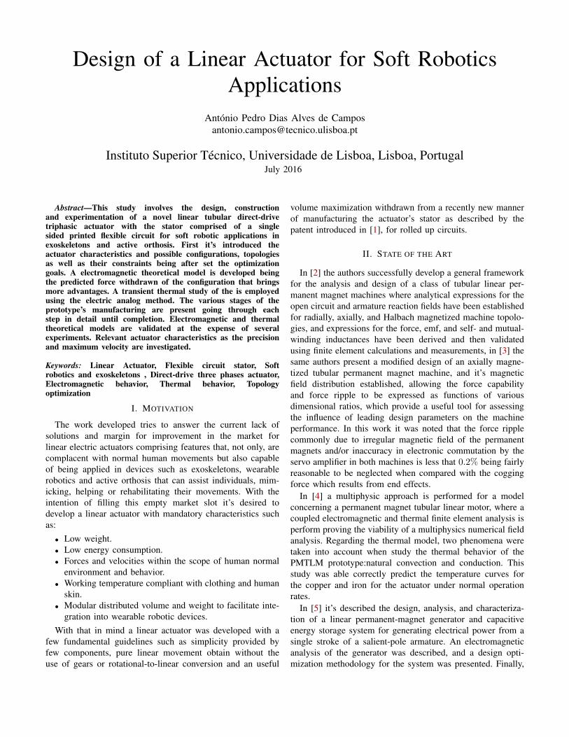
Design of a Linear Actuator for Soft RoboticsApplications
António Pedro Dias Alves de [email protected]
Instituto Superior Técnico, Universidade de Lisboa, Lisboa, PortugalJuly 2016
Abstract—This study involves the design, constructionand experimentation of a novel linear tubular direct-drivetriphasic actuator with the stator comprised of a singlesided printed flexible circuit for soft robotic applications inexoskeletons and active orthosis. First it’s introduced theactuator characteristics and possible configurations, topologiesas well as their constraints being after set the optimizationgoals. A electromagnetic theoretical model is developed beingthe predicted force withdrawn of the configuration that bringsmore advantages. A transient thermal study of the is employedusing the electric analog method. The various stages of theprototype’s manufacturing are present going through eachstep in detail until completion. Electromagnetic and thermaltheoretical models are validated at the expense of severalexperiments. Relevant actuator characteristics as the precisionand maximum velocity are investigated.
Keywords: Linear Actuator, Flexible circuit stator, Softrobotics and exoskeletons , Direct-drive three phases actuator,Electromagnetic behavior, Thermal behavior, Topologyoptimization
I. MOTIVATION
The work developed tries to answer the current lack ofsolutions and margin for improvement in the market forlinear electric actuators comprising features that, not only, arecomplacent with normal human movements but also capableof being applied in devices such as exoskeletons, wearablerobotics and active orthosis that can assist individuals, mim-icking, helping or rehabilitating their movements. With theintention of filling this empty market slot it’s desired todevelop a linear actuator with mandatory characteristics suchas:
• Low weight.• Low energy consumption.• Forces and velocities within the scope of human normal
environment and behavior.• Working temperature compliant with clothing and human
skin.• Modular distributed volume and weight to facilitate inte-
gration into wearable robotic devices.With that in mind a linear actuator was developed with a
few fundamental guidelines such as simplicity provided byfew components, pure linear movement obtain without theuse of gears or rotational-to-linear conversion and an useful
volume maximization withdrawn from a recently new mannerof manufacturing the actuator’s stator as described by thepatent introduced in [1], for rolled up circuits.
II. STATE OF THE ART
In [2] the authors successfully develop a general frameworkfor the analysis and design of a class of tubular linear per-manent magnet machines where analytical expressions for theopen circuit and armature reaction fields have been establishedfor radially, axially, and Halbach magnetized machine topolo-gies, and expressions for the force, emf, and self- and mutual-winding inductances have been derived and then validatedusing finite element calculations and measurements, in [3] thesame authors present a modified design of an axially magne-tized tubular permanent magnet machine, and it’s magneticfield distribution established, allowing the force capabilityand force ripple to be expressed as functions of variousdimensional ratios, which provide a useful tool for assessingthe influence of leading design parameters on the machineperformance. In this work it was noted that the force ripplecommonly due to irregular magnetic field of the permanentmagnets and/or inaccuracy in electronic commutation by theservo amplifier in both machines is less that 0.2% being fairlyreasonable to be neglected when compared with the coggingforce which results from end effects.
In [4] a multiphysic approach is performed for a modelconcerning a permanent magnet tubular linear motor, where acoupled electromagnetic and thermal finite element analysis isperform proving the viability of a multiphysics numerical fieldanalysis. Regarding the thermal model, two phenomena weretaken into account when study the thermal behavior of thePMTLM prototype:natural convection and conduction. Thisstudy was able correctly predict the temperature curves forthe copper and iron for the actuator under normal operationrates.
In [5] it’s described the design, analysis, and characteriza-tion of a linear permanent-magnet generator and capacitiveenergy storage system for generating electrical power from asingle stroke of a salient-pole armature. An electromagneticanalysis of the generator was described, and a design opti-mization methodology for the system was presented. Finally,

the performance of a prototype was validated against mea-surements, having concluded that predicted performance agreewell with experimental results for the generator prototype.
An investigation of the influence of the choice of softmagnetic material on the performance of a tubular permanentmagnet machine was conducted in [6], and quantified therelative merits of silicon iron laminations and soft magneticcomposites (SMCs). The machines here studied are equippedwith a modular stator winding and employs a quasi-Halbachmagnetized moving-magnet armature. It was shown that, de-spite its poorer space utilization, a machine whose stator isfabricated from silicon iron laminations has the highest forcecapability, efficiency and power factor. A machine with a SMCstator, on the other hand, has potential advantages in terms ofease of manufacture and lower cost.
In the pursuit of a bendable motor [7] presents a new two-phase flexible linear actuator. It’s flexibility due to elastomersoffer the desired actuator flexibility both between the coils ofthe stator and between the magnets in the mover. Various finiteelement models were developed, optimizing the dimensionalparameters until reaching the desired values. Regarding exper-imental tests, weights up to 750 g were lifted with a minimalbending radius of 200 mm as well as holding force densitiesof 49 N/kg in continuous operation.
The authors of [8] present a design and analysis frame-work for the general class of permanent-magnet electricalmachines. In their work they present a surface-mounted linearmotors consisting of permanent magnets and iron-less current-carrying coils, they are treated in a uniform way via themagnetic vector potential. This design is accomplished withthe purpose of developing novel linear magnetic levitators fordriving precision motion control stages.
In [9] a novel modeling design of a three phase tubular PMlinear generator is proposed as well as the system definitionis presented and analyzed. A parametric evaluation of the ma-chine is done to enforce a finite element model. A parametricapproach is adopted to perform a first optimization of TPM-LiG electromagnetic behavior, and the specified features areachieved.
In [10] formulation of the magnetic flux distribution oftubular linear machines based on magnetic vector potential,Laplace’s and Poisson equations is performed. The magneticfield model is validated with FEM results, and employed toanalyze the effect of structure parameters on the magneticfield. The results of this paper, as stated by the authors, can beemployed to study the force output and design optimizationof tubular linear motors in the future.
III. PROTOTYPE DESCRIPTION
The proposed tubular linear actuator is comprised of twodistinct parts called mover, the inner part, and stator, the staticouter one. The stator by current excitation will generate amagnetic field that will interact with the a permanent fieldcreated by the mover’s magnetic rings producing the desiredlinear movement.
A. Prototype Topology and Variables
The mover, inner part, is made of a set of permanent magnetrings sequentially placed in a carbon rod as shown in fig.1,together they make up all mover’s components.
Stator windings
Magnet rings
Carbon rod
Fig. 1: Actuator’s configuration and main components.In turn, the stator is made of a rolled up sheet of flexible
circuit, to this approach of build the stator windings, per say,without the usage of actual copper filamented wires and aframe to hold them an keep them in the correct place, isdevoted a special attention due to the fact that’s the firsttime that’s constructed and essayed a linear actuator with thistechnology.
1) Mover: The inner part of the actuator, is comprised ofa series of axial magnetized rings sequentially placed alonga carbon rod with inversed polarities in such a way that allneighbor rings repel each other. The rings are made from analloy of neodymium. Dimension-wise (Fig.2), they have aninner and outer diameters rmi and rmo respectively, and anhight designed by hm. They fit perfectly into the carbon rod,due to it’s radius being equal to the inner one, rmi, of thepermanent magnets.
Fig. 2: Mover’s neodymium rings and carbon rod dimensions.
The rings are axially magnetized, i.e. the magnetizationdirection is along their geometric axis, being the north andsouth poles located on their flat faces. Other important magnetrings’ variables are the ones necessary to fully define anelectromagnetic model and they are: the Remanence FluxBr, Coercive Force Hcb, and Magnetic Relative Permeability(BH)max.
2) Stator: The stator is comprised of only one component,an flexible sheet of circuit. Contrary to common linear actua-tors that have to rely in sequentially placed coils of rolled upcopper wire to induce a magnetic field, the stator’s actuatorstudied is made of a sheet of flexible circuit that is rolled upforming an hollow cylinder. This sheet has two layers, thebottom layer is made of a polymide composite with thicknessτpc, and has structural purposes and the top layer is a thinfoil of copper of thickness τct (see Fig.4), that is transformedin a circuitry of copper traces after a revelation procedure.The flexible sheet of circuit is then rolled up like in Fig.3making the same effect as copper windings with the up frontadvantage of being just a single piece of composite materialinstead of a large set of components requiring a complex
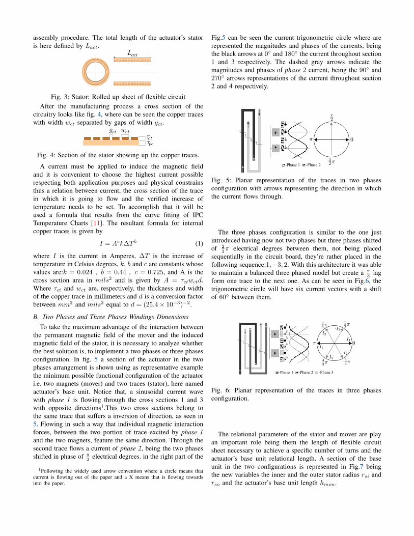
assembly procedure. The total length of the actuator’s statoris here defined by Lact.
L act
Fig. 3: Stator: Rolled up sheet of flexible circuitAfter the manufacturing process a cross section of the
circuitry looks like fig. 4, where can be seen the copper traceswith width wct separated by gaps of width gct.
Fig. 4: Section of the stator showing up the copper traces.
A current must be applied to induce the magnetic fieldand it is convenient to choose the highest current possiblerespecting both application purposes and physical constrainsthus a relation between current, the cross section of the tracein which it is going to flow and the verified increase oftemperature needs to be set. To accomplish that it will beused a formula that results from the curve fitting of IPCTemperature Charts [11]. The resultant formula for internalcopper traces is given by
I = Ack∆T b (1)
where I is the current in Amperes, ∆T is the increase oftemperature in Celsius degrees, k, b and c are constants whosevalues are:k = 0.024 , b = 0.44 , c = 0.725, and A is thecross section area in mils2 and is given by A = τctwctd.Where τct and wct are, respectively, the thickness and widthof the copper trace in millimeters and d is a conversion factorbetween mm2 and mils2 equal to d = (25.4× 10⁻³)−2.
B. Two Phases and Three Phases Windings Dimensions
To take the maximum advantage of the interaction betweenthe permanent magnetic field of the mover and the inducedmagnetic field of the stator, it is necessary to analyze whetherthe best solution is, to implement a two phases or three phasesconfiguration. In fig. 5 a section of the actuator in the twophases arrangement is shown using as representative examplethe minimum possible functional configuration of the actuatori.e. two magnets (mover) and two traces (stator), here namedactuator’s base unit. Notice that, a sinusoidal current wavewith phase 1 is flowing through the cross sections 1 and 3with opposite directions1.This two cross sections belong tothe same trace that suffers a inversion of direction, as seen in5. Flowing in such a way that individual magnetic interactionforces, between the two portion of trace excited by phase 1and the two magnets, feature the same direction. Through thesecond trace flows a current of phase 2, being the two phasesshifted in phase of π
2 electrical degrees. in the right part of the
1Following the widely used arrow convention where a circle means thatcurrent is flowing out of the paper and a X means that is flowing towardsinto the paper.
Fig.5 can be seen the current trigonometric circle where arerepresented the magnitudes and phases of the currents, beingthe black arrows at 0 and 180 the current throughout section1 and 3 respectively. The dashed gray arrows indicate themagnitudes and phases of phase 2 current, being the 90 and270 arrows representations of the current throughout section2 and 4 respectively.
1
2
3 4
-Phase 1 -Phase 2
2
1
3
4
Fig. 5: Planar representation of the traces in two phasesconfiguration with arrows representing the direction in whichthe current flows through.
The three phases configuration is similar to the one justintroduced having now not two phases but three phases shiftedof 2
3π electrical degrees between them, not being placedsequentially in the circuit board, they’re rather placed in thefollowing sequence:1,−3, 2. With this architecture it was ableto maintain a balanced three phased model but create a π
3 lagform one trace to the next one. As can be seen in Fig.6, thetrigonometric circle will have six current vectors with a shiftof 60 between them.
1
2 3
45
6
-Phase 1 -Phase 2 -Phase 3
1
2
3
4
5
6
Fig. 6: Planar representation of the traces in three phasesconfiguration.
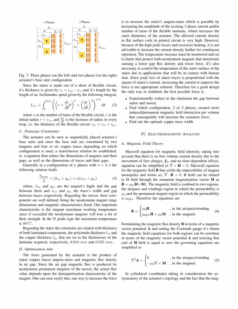
The relational parameters of the stator and mover are playan important role being them the length of flexible circuitsheet necessary to achieve a specific number of turns and theactuator’s base unit relational length. A section of the baseunit in the two configurations is represented in Fig.7 beingthe new variables the inner and the outer stator radius rsi andrso and the actuator’s base unit length hmon.
2 Phases 3 Phases
Fig. 7: Three phases (on the left) and two phases (on the right)actuator’s base unit configuration.
Since the stator is made out of a sheet of flexible circuit,it’s thickness is given by τs = rso− rsi and it’s length by thelength of an Archimedes spiral given by the following integral,
Lfc =
∫ 2πn
0
((r +
dr
dθθ
)2
+
(dr
dθ
)2)1/2
dθ (2)
where n is the number of turns of the flexible circuit, r is theinitial radius r = rsi, and dr
dθ is the increase of radius in everyloop, i.e. the thickness of the flexible circuit τfc = τct + τpc.
C. Prototype Constraints
The actuator can be seen as sequentially placed actuator’sbase units and since the base unit are constituted by twomagnets and four or six copper traces depending on whichconfiguration is used, a stator/mover relation be established,ie. a equation than relates the dimensions of magnets and theirgaps, as well as the dimensions of traces and their gaps.
Generally in a configuration of n phases with n = 2, 3 thefollowing relation holds
hmon2
= (hm + gm) = n(wct + gct) (3)
where, hm and gm are the magnet’s hight and the gapbetween them and wct and gct the trace’s width and gapbetween traces respectively. Regarding the mover, their com-ponents are well defined, being the neodymium magnet ringsdimensions and magnetic characteristics fixed. One importantcharacteristic is the magnet maximum working temperaturesince if exceeded the neodymium magnets will lose a lot oftheir strength. In the N grade type the maximum temperatureis 80C.
Regarding the stator the constrains are related with thicknessof both laminated components, the polyimide thickness tct andthe copper thickness tpc that are set to the thicknesses of thelaminate acquired, respectively, 0.018 mm and 0.025 mm.
D. Optimization Aim
The force generated by the actuator is the product ofstator copper traces ampere-turns and magnetic flux densityin air gap. Since the air gap magnetic flux is produced byneodymium permanent magnets of the mover, the actual fluxvalue depends upon the demagnetization characteristic of themagnet. One can seen easily that, one way to increase the force
is to increase the stator’s ampere-turns which is possible byincreasing the amplitude of the exciting 3 phase current and/ornumber of turns of the flexible laminate, which increases theouter diameters of the actuator. The allowed current densityin flat surface coils in printed circuit is very high. However,because of the high joule losses and excessive heating, it is notadvisable to increase the current density further for continuousoperation. The temperature increase must be monitored and setto limits that protect both neodymium magnets that deterioratecausing a lower gap flux density and lower force. It’s alsonecessary to control the temperature of the outer surface of thestator due to applications that will be in contact with humanskin. Since joule loss of stator traces is proportional with thesquare of stator’s current, increasing the current to improve theforce is not appropriate solution. Therefore for a good designthe only way to withdraw the best possible force is:
• Experimentally reduce to the minimum the gap betweenstator and mover.
• Find which configuration, 2 or 3 phases, created moreinduced/permanent magnetic field interaction per volumethat consequently will increase the actuators force.
• Find out the optimal copper trace width.
IV. ELECTROMAGNETIC ANALYSIS
A. Magnetic Field Theory
Maxwell equation for magnetic field intensity, taking intoaccount that there is no free volume current density due to themovement of free charges, Jf , and no time-dependent effects,equation can be simplified to ∇× H = 0. Maxwell equationfor the magnetic field B that yields the impossibility of magnetmonopoles and writes as, ∇ · B = 0. B field can be relatedto H field through the remanent magnetization vector M asB = µ0(H+M). The magnetic field is confined to two regions,the airspace and windings region in which the permeability isµ0 and the permanent magnet region in which the permeabilityis µ0µr. Therefore the equations are
B =
µ0H , in the airspace/windingµ0µrH + µ0M , in the magnets
(4)
Formulating the magnetic flux density B in terms of a magneticvector potential A and setting the Coulomb gauge it’s obtainthe magnetic field equations for both regions can be rewrittenin terms of the magnetic vector potential A and noticing thatcurl of H field is equal to zero the governing equations aresimplified to
∇2A =
0 , in the airspace/winding−µ0∇×M , in the magnets
(5)
In cylindrical coordinates taking in consideration the ax-isymmetry of the actuator’s topology and the fact that the mag-

netization vector M only has z component, i.e. M = Mzezthe equations can be rewritten, as
∂
∂r
(1
r
∂(rAIθ)
∂r
)+
∂
∂z
(1
r
∂(rAIθ)
∂z
)= 0 ,
in the airspace/winding∂
∂r
(1
r
∂(rAIIθ)
∂r
)+
∂
∂z
(1
r
∂(rAIIθ)
∂z
)= 0 ,
in the magnets
(6)
B. Actuation Force
The force output delivered by the actuator is proportionalto the current applied the their phases. The force betweenone magnet and one coil as a function of current at manyrelative displacements was calculated using the Lorentz forceequation F =
∫(J×B)dV . Since each magnet in the array is
assumed to be positioned at the axial center of the coils, ther-component of the force will cancel out. The remaining forceis only in the z-direction
Fz =
∫(−Jθ ×Br) dV (7)
V. FINITE ELEMENT MODEL
A finite elements study was conducted in order to find theactuator’s configuration and related parameters so that the bestperformance criteria are meet. This analysis was performedusing FEMM - Finite Element Method Magnetics.
A. 3 Phase vs 2 Phase
To evaluate the desired configuration, three or two phases,and the copper trace width wct that ensures the maximumforce, a study was conducted. For both, two and three phasescircuit configuration it was varied the relative position of themover in respect to the stator (Zm) from a set position Zm =0% to Zm = hmon, i.e. the mover travels a length equivalentto the length of it’s base unit. Then for each of those positionswas simulated the variation of intensity in the electrical phasesfrom 0 to 2π. The result obtained was a surface correspondingto the force produced by the actuator for each position andinstantaneous current intensity as seen in Fig. 8. A section ofthe surface at a constant mover position Zm = 10% for thethree phase configuration is shown in figure 9 where can beseen the force curve and the correspondent three phases valuesof the actuator copper traces.
360330300270240
Current Phase [ ]
2101801501209060301020304050
Normalized Mover position Zm
60708090100
-0.12
-0.17
0.03
-0.22
0.18
0.13
0.08
-0.02
-0.07
For
ce [N
]
Fig. 8: Force surface.
Phase [rad]0 1 2 3 4 5 6
For
ce [N
]
-0.2
-0.15
-0.1
-0.05
0
0.05
0.1
0.15
0.2
Cur
rent
[A]
-0.8
-0.6
-0.4
-0.2
0
0.2
0.4
0.6
0.8
ForcePhase 1Phase 2Phase 3
Fig. 9: Force plot and correspondent three phase currentsintensity at Zm = 10% of total actuator’s base unit length.
This force surface study was developed for different typesof copper trace widths wct, for both two and three phasesconfiguration, yielding the results present in Figure 10, wherecan be seen two lines, the red dashed line is the mean ofthe maximum absolute force’s per unit length values alongsections of constant mover’s position for different coppertrace’s length. The black continuous line represent for eachcopper trace width the value with higher probability densitybased on a normal kernel function.
ct[mm]
0.5 0.6 0.7 0.8 0.9 1 1.1 1.2
For
ce p
er L
engt
h [N
/mm
]
0.03
0.035
0.04
0.045
mean( Fmax/min
)
max [ KS(Fmax/min
) ]
Copper Trace Width Wct[mm]
0.8 1 1.2 1.4 1.6 1.8 2
For
ce p
er L
engt
h [N
/mm
]
0.026
0.028
0.03
0.032
0.034
0.036
0.038
0.04
0.042
0.044
mean( Fmax/min
)
max[ KS(Fmax/min
) ]
Copper Trace Width W
Fig. 10: Two (left) and Three (right) Phases Force for differentcopper traces length
In both, these two graphics and in a two versus threephases comparative graphic in figure 11, can be seen that
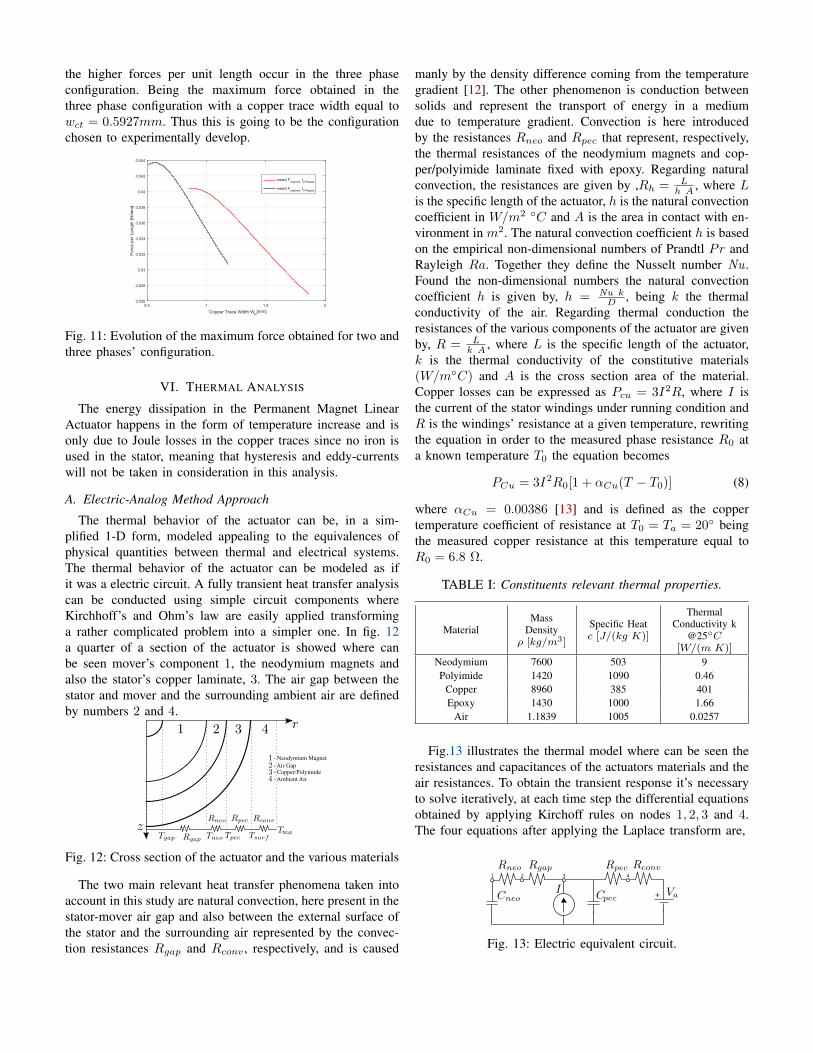
the higher forces per unit length occur in the three phaseconfiguration. Being the maximum force obtained in thethree phase configuration with a copper trace width equal towct = 0.5927mm. Thus this is going to be the configurationchosen to experimentally develop.
ct[mm]
0.5 1 1.5 2
For
ce p
er L
engt
h [N
/mm
]
0.026
0.028
0.03
0.032
0.034
0.036
0.038
0.04
0.042
0.044
mean( Fmax/min
)2 Phases
mean( Fmax/min
)3 Phases
Copper Trace Width W
Fig. 11: Evolution of the maximum force obtained for two andthree phases’ configuration.
VI. THERMAL ANALYSIS
The energy dissipation in the Permanent Magnet LinearActuator happens in the form of temperature increase and isonly due to Joule losses in the copper traces since no iron isused in the stator, meaning that hysteresis and eddy-currentswill not be taken in consideration in this analysis.
A. Electric-Analog Method Approach
The thermal behavior of the actuator can be, in a sim-plified 1-D form, modeled appealing to the equivalences ofphysical quantities between thermal and electrical systems.The thermal behavior of the actuator can be modeled as ifit was a electric circuit. A fully transient heat transfer analysiscan be conducted using simple circuit components whereKirchhoff’s and Ohm’s law are easily applied transforminga rather complicated problem into a simpler one. In fig. 12a quarter of a section of the actuator is showed where canbe seen mover’s component 1, the neodymium magnets andalso the stator’s copper laminate, 3. The air gap between thestator and mover and the surrounding ambient air are definedby numbers 2 and 4.
- Neodymium Magnet- Air Gap- Copper/Polyimide - Ambient Air
Fig. 12: Cross section of the actuator and the various materials
The two main relevant heat transfer phenomena taken intoaccount in this study are natural convection, here present in thestator-mover air gap and also between the external surface ofthe stator and the surrounding air represented by the convec-tion resistances Rgap and Rconv , respectively, and is caused
manly by the density difference coming from the temperaturegradient [12]. The other phenomenon is conduction betweensolids and represent the transport of energy in a mediumdue to temperature gradient. Convection is here introducedby the resistances Rneo and Rpec that represent, respectively,the thermal resistances of the neodymium magnets and cop-per/polyimide laminate fixed with epoxy. Regarding naturalconvection, the resistances are given by ,Rh = L
h A , where Lis the specific length of the actuator, h is the natural convectioncoefficient in W/m2 C and A is the area in contact with en-vironment in m2. The natural convection coefficient h is basedon the empirical non-dimensional numbers of Prandtl Pr andRayleigh Ra. Together they define the Nusselt number Nu .Found the non-dimensional numbers the natural convectioncoefficient h is given by, h = Nu k
D , being k the thermalconductivity of the air. Regarding thermal conduction theresistances of the various components of the actuator are givenby, R = L
k A , where L is the specific length of the actuator,k is the thermal conductivity of the constitutive materials(W/mC) and A is the cross section area of the material.Copper losses can be expressed as Pcu = 3I2R, where I isthe current of the stator windings under running condition andR is the windings’ resistance at a given temperature, rewritingthe equation in order to the measured phase resistance R0 ata known temperature T0 the equation becomes
PCu = 3I2R0[1 + αCu(T − T0)] (8)
where αCu = 0.00386 [13] and is defined as the coppertemperature coefficient of resistance at T0 = Ta = 20 beingthe measured copper resistance at this temperature equal toR0 = 6.8 Ω.
TABLE I: Constituents relevant thermal properties.
MaterialMass
Densityρ [kg/m3]
Specific Heatc [J/(kg K)]
ThermalConductivity k
@25C[W/(m K)]
Neodymium 7600 503 9Polyimide 1420 1090 0.46
Copper 8960 385 401Epoxy 1430 1000 1.66
Air 1.1839 1005 0.0257
Fig.13 illustrates the thermal model where can be seen theresistances and capacitances of the actuators materials and theair resistances. To obtain the transient response it’s necessaryto solve iteratively, at each time step the differential equationsobtained by applying Kirchoff rules on nodes 1, 2, 3 and 4.The four equations after applying the Laplace transform are,
+
1 2 3 4
Fig. 13: Electric equivalent circuit.
Node 1: Jneo(Vneo − Vgap)− sCneoVneo = 0
Node 2: Jgap(Vpec − Vgap)− Jneo(Vgap − Vneo) = 0
Node 3: I − Iinner − Jgap(Vpec − Vgap)− sCpecVpec = 0
Node 4: Jpec(Vpec − Vsurf )− JconvVsurf = 0
The values for resistances and capacitances that allow thecomputation of the temperature rise are present in Table II.
TABLE II: Resistances and capacitances of the thermal net-work.
Parameter ValueCneo 92.843 [J/W ]
Rneo 0.1766 [K/W ]
Rgap 1.213 [K/W ]
Cpec 77.157 [J/W ]
Rpec 0.083 [K/W ]
Rconv 0.713 [K/W ]
In figure 14 can be seen the evolution of the temperaturerises for the actuator’s different parts during the it’s ownoperating period. Two curves have a special interest, curvesTsurf and Tneo. Tneo represents the temperature evolution inthe neodymium magnets. Since the temperature in magnetscan’t surpass 80V in order to not lose it’s own magnetization.The second curve is Tsurf and represents the temperatureevolution at the stator’s surface, being crucial to monitor sincein applications that the actuator is in direct contact with skin,temperature rises can be harmful2.
Time [s]0 100 200 300 400 500 600 700 800 900 1000
Tem
pera
ture
[K]
295
300
305
310
315
320
325
330
335
340
345
Tgap
Tneo
Tpec
Tsurf
Fig. 14: Temperature increase of the various components ofthe actuator.
Thus it’s set as maximum operating time 300 seconds (5minutes). That ensures that the temperature in the neodymiummagnets does not get higher than 337.5K or 64.35C and thestator outer surface does not surpasses 318K or 44.85C.
VII. PROTOTYPE MANUFACTURING
A. Stator Stage - Printing, Developing and Etching
The first step in the actuator’s manufacturing process is thecreation of the stator. The actuator’s stator is made of only one
2According to the National Institute of Standards and Technology (NIST)in U.S. temperatures above 48C can inflict first degree burn injuries in thehuman skin.
component, a rolled up flexible copper laminate sheet. Themanufacturing process starts with a sheet of flexible single-sided cooper clad laminated sheet, this particular sheet is madeof a combination of a copper thin foil with a thickness of18 µm binded to a polyimide composite layer of 25 µm, tothis flexible sheet is applied a photosensitive resist that, whenexposed to light, loses its resistance or it’s susceptibility to beattacked by an etchant or solvent. In order to print the desiredcircuit it was used the laser printer to draw the desired tracesin the flexible copper laminate.
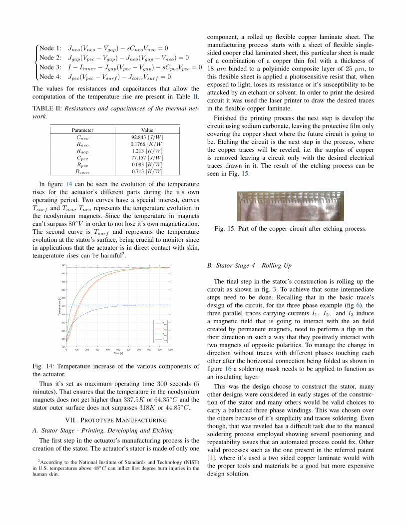
Finished the printing process the next step is develop thecircuit using sodium carbonate, leaving the protective film onlycovering the copper sheet where the future circuit is going tobe. Etching the circuit is the next step in the process, wherethe copper traces will be reveled, i.e. the surplus of copperis removed leaving a circuit only with the desired electricaltraces drawn in it. The result of the etching process can beseen in Fig. 15.
Fig. 15: Part of the copper circuit after etching process.
B. Stator Stage 4 - Rolling Up
The final step in the stator’s construction is rolling up thecircuit as shown in fig. 3. To achieve that some intermediatesteps need to be done. Recalling that in the basic trace’sdesign of the circuit, for the three phase example (fig 6), thethree parallel traces carrying currents I1, I2, and I3 inducea magnetic field that is going to interact with the an fieldcreated by permanent magnets, need to perform a flip in thetheir direction in such a way that they positively interact withtwo magnets of opposite polarities. To manage the change indirection without traces with different phases touching eachother after the horizontal connection being folded as shown infigure 16 a soldering mask needs to be applied to function asan insulating layer.
This was the design choose to construct the stator, manyother designs were considered in early stages of the construc-tion of the stator and many others would be valid choices tocarry a balanced three phase windings. This was chosen overthe others because of it’s simplicity and traces soldering. Eventhough, that was reveled has a difficult task due to the manualsoldering process employed showing several positioning andrepeatability issues that an automated process could fix. Othervalid processes such as the one present in the referred patent[1], where it’s used a two sided copper laminate would withthe proper tools and materials be a good but more expensivedesign solution.
I I I 1 2 3 1 2 3I I I
Fig. 16: Three phase configuration.
After being soldered and the connection closed, as shownin figure 16 the flexible circuit should look like the circuit infigure 17
Fig. 17: Soldered traces. All three phases’ traces of the circuitare now connected.
Completed the manufacture process of the flexible circuitthe last step is to roll up the circuit to make a rigid statormade of only on component as shown in figure 18.
Fig. 18: Rolling up process of the flexible circuit.
C. Rotor Stage 1 - Assembly
The rotor assembly was perform in such a way thatminimum parts and low complexity, following the line ofthought of the actuator proposed in this thesis, are a importantrequirement. Stated that the rotor is assembly just by placingsequentially magnetic rings in an carbon rod. The final proto-type can be seen in fig. 19.
Fig. 19: Mover, where can be seen the sequentially placedmagnetic rings.
VIII. PRACTICAL RESULTS AND ANALYSIS
A. Electromagnetic Model Validation
In order to correctly validate the prototype’s theoreticalelectromagnetic model developed three distinct experiments
were conducted. The first one, likewise it was done in SectionV-A, consists in the characterization of force experienced bya locked mover for several positions from 0 to 100% of thelength of one actuator’s base unit (hmon), experiencing ateach discrete position the influence of the three current phaseschanging their phases from 0 to 360. Figure 20(left) showshighlighted one actuator’s base unit length to better understandthe travel this distance of the mover.
The second experiment consists in performing the sameexperience, i.e. locking the mover in several positions and foreach position vary the current along the three phases in sucha way that they perform a whole trigonometric circle (0 to360), but with small difference. The mover, instead of onlytravel a distance correspondent to the length of one actuator’sbase unit travels 65.024 mm, the length of 8 base units whereat each step the force is acquired as can be seen in figure 20.
The last experiment conducted was the acquisition of thevariation of force that the mover experienced locked in it’scentral position with a imposed variation of current in thewindings. Being able to compare the theoretical e experimentalforces as function of the phases’ currents.
Fig. 20: Highlighted actuator’s base unit length to forceacquisition (on the left) and Stroke length for the secondexperiment of force acquisition (on the right).
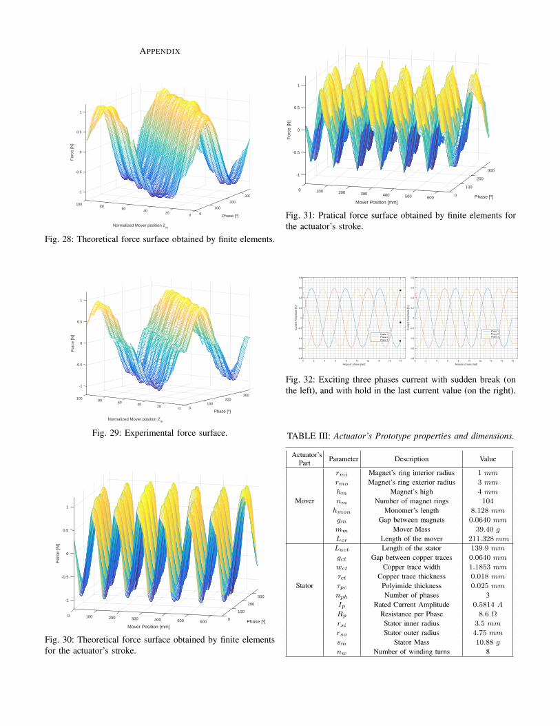
In the table III(in Appendix section), can be seen all relevantcharacteristics of the prototype developed. It wa selected forconstruction the three phase configuration with a copper tracewidth of wct = 0.5927mm. In figure 28(in Appendix section)can be seen the force surface obtain by finite elements pro-gram, FEMM, when varied the current phases along differentmovers position within the length of one actuator’s base unit.The Mover is excited by the signals feed to the three phases,having a peak amplitude value of Ipeak = 0.5814 A, astabulated in the table above.
In figure 29(in Appendix section) it’s present the experimen-tal curve acquired using a scale with a precision of 0.01 grams.Being the surface comprised of 6624 measurements. In figure21 it’s plotted the difference between the predicted valuesand the values obtained in the experimental measurements.The errors between the two surfaces are more prominent,as expected due to the sine wave nature, the places wheremaximum and minimum forces occur. Being the maximumerror relative to the experimental value of 16.08%. The lowerforces experienced by the actuator in the experimental can berelated to main three factors: The friction present between themover and the stator since it was necessary to add kaptonfilm in several places to ensure a perfectly concentric moverand stator. Even though the areas of contact added betweenthe stator and mover where ensured to be the minimum ones
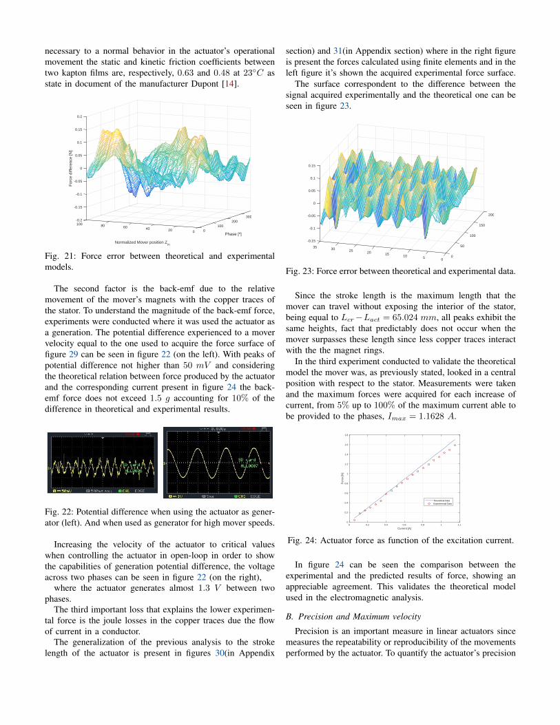
necessary to a normal behavior in the actuator’s operationalmovement the static and kinetic friction coefficients betweentwo kapton films are, respectively, 0.63 and 0.48 at 23C asstate in document of the manufacturer Dupont [14].
300
Phase [º]
200100
0020
Normalized Mover position Zm
406080100-0.2
0.1
0.15
0
-0.05
0.05
-0.1
-0.15
0.2
For
ce d
iffer
ence
[N]
Fig. 21: Force error between theoretical and experimentalmodels.
The second factor is the back-emf due to the relativemovement of the mover’s magnets with the copper traces ofthe stator. To understand the magnitude of the back-emf force,experiments were conducted where it was used the actuator asa generation. The potential difference experienced to a movervelocity equal to the one used to acquire the force surface offigure 29 can be seen in figure 22 (on the left). With peaks ofpotential difference not higher than 50 mV and consideringthe theoretical relation between force produced by the actuatorand the corresponding current present in figure 24 the back-emf force does not exceed 1.5 g accounting for 10% of thedifference in theoretical and experimental results.
Fig. 22: Potential difference when using the actuator as gener-ator (left). And when used as generator for high mover speeds.
Increasing the velocity of the actuator to critical valueswhen controlling the actuator in open-loop in order to showthe capabilities of generation potential difference, the voltageacross two phases can be seen in figure 22 (on the right),
where the actuator generates almost 1.3 V between twophases.
The third important loss that explains the lower experimen-tal force is the joule losses in the copper traces due the flowof current in a conductor.
The generalization of the previous analysis to the strokelength of the actuator is present in figures 30(in Appendix
section) and 31(in Appendix section) where in the right figureis present the forces calculated using finite elements and in theleft figure it’s shown the acquired experimental force surface.
The surface correspondent to the difference between thesignal acquired experimentally and the theoretical one can beseen in figure 23.
200
150
100
50
005101520253035
0.15
-0.15
-0.1
-0.05
0
0.05
0.1
Fig. 23: Force error between theoretical and experimental data.
Since the stroke length is the maximum length that themover can travel without exposing the interior of the stator,being equal to Lcr−Lact = 65.024 mm, all peaks exhibit thesame heights, fact that predictably does not occur when themover surpasses these length since less copper traces interactwith the the magnet rings.
In the third experiment conducted to validate the theoreticalmodel the mover was, as previously stated, looked in a centralposition with respect to the stator. Measurements were takenand the maximum forces were acquired for each increase ofcurrent, from 5% up to 100% of the maximum current able tobe provided to the phases, Imax = 1.1628 A.
Current [A]0 0.2 0.4 0.6 0.8 1 1.2
For
ce [N
]
0
0.2
0.4
0.6
0.8
1
1.2
1.4
1.6
1.8
Theoretical DataExperimental Data
Fig. 24: Actuator force as function of the excitation current.
In figure 24 can be seen the comparison between theexperimental and the predicted results of force, showing anappreciable agreement. This validates the theoretical modelused in the electromagnetic analysis.
B. Precision and Maximum velocity
Precision is an important measure in linear actuators sincemeasures the repeatability or reproducibility of the movementsperformed by the actuator. To quantify the actuator’s precision
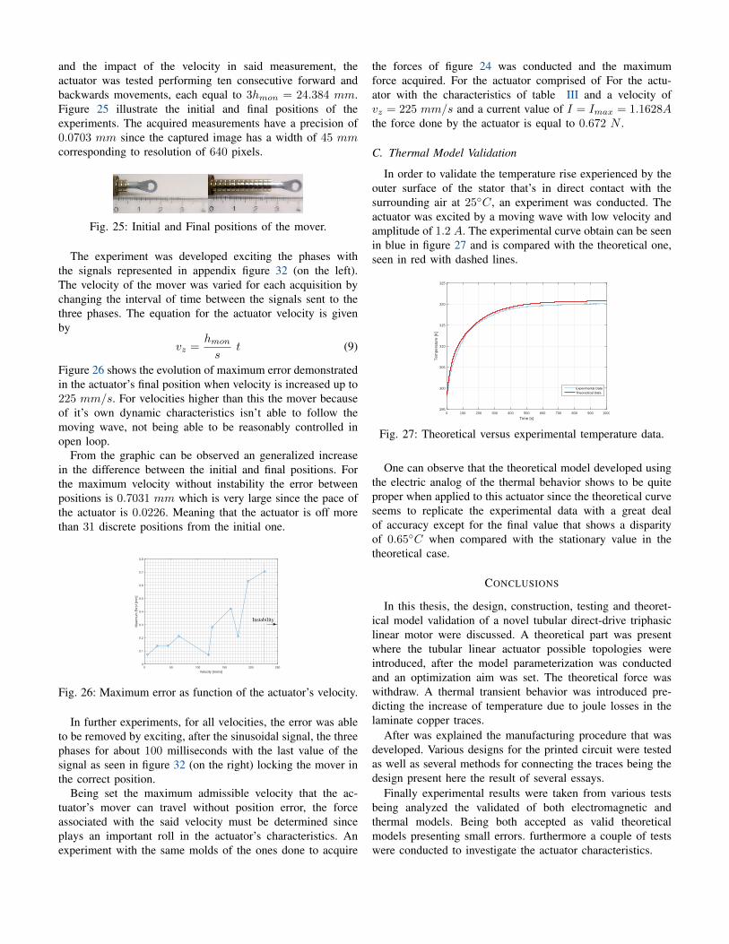
and the impact of the velocity in said measurement, theactuator was tested performing ten consecutive forward andbackwards movements, each equal to 3hmon = 24.384 mm.Figure 25 illustrate the initial and final positions of theexperiments. The acquired measurements have a precision of0.0703 mm since the captured image has a width of 45 mmcorresponding to resolution of 640 pixels.
Fig. 25: Initial and Final positions of the mover.
The experiment was developed exciting the phases withthe signals represented in appendix figure 32 (on the left).The velocity of the mover was varied for each acquisition bychanging the interval of time between the signals sent to thethree phases. The equation for the actuator velocity is givenby
vz =hmons
t (9)
Figure 26 shows the evolution of maximum error demonstratedin the actuator’s final position when velocity is increased up to225 mm/s. For velocities higher than this the mover becauseof it’s own dynamic characteristics isn’t able to follow themoving wave, not being able to be reasonably controlled inopen loop.
From the graphic can be observed an generalized increasein the difference between the initial and final positions. Forthe maximum velocity without instability the error betweenpositions is 0.7031 mm which is very large since the pace ofthe actuator is 0.0226. Meaning that the actuator is off morethan 31 discrete positions from the initial one.
Velocity [mm/s]0 50 100 150 200 250
Max
imum
Err
or [m
m]
0
0.1
0.2
0.3
0.4
0.5
0.6
0.7
0.8
Instability
Fig. 26: Maximum error as function of the actuator’s velocity.
In further experiments, for all velocities, the error was ableto be removed by exciting, after the sinusoidal signal, the threephases for about 100 milliseconds with the last value of thesignal as seen in figure 32 (on the right) locking the mover inthe correct position.
Being set the maximum admissible velocity that the ac-tuator’s mover can travel without position error, the forceassociated with the said velocity must be determined sinceplays an important roll in the actuator’s characteristics. Anexperiment with the same molds of the ones done to acquire
the forces of figure 24 was conducted and the maximumforce acquired. For the actuator comprised of For the actu-ator with the characteristics of table III and a velocity ofvz = 225 mm/s and a current value of I = Imax = 1.1628Athe force done by the actuator is equal to 0.672 N .
C. Thermal Model Validation
In order to validate the temperature rise experienced by theouter surface of the stator that’s in direct contact with thesurrounding air at 25C, an experiment was conducted. Theactuator was excited by a moving wave with low velocity andamplitude of 1.2 A. The experimental curve obtain can be seenin blue in figure 27 and is compared with the theoretical one,seen in red with dashed lines.
Time [s]0 100 200 300 400 500 600 700 800 900 1000
Tem
pera
ture
[K]
295
300
305
310
315
320
325
Experimental DataTheorectical Data
Fig. 27: Theoretical versus experimental temperature data.
One can observe that the theoretical model developed usingthe electric analog of the thermal behavior shows to be quiteproper when applied to this actuator since the theoretical curveseems to replicate the experimental data with a great dealof accuracy except for the final value that shows a disparityof 0.65C when compared with the stationary value in thetheoretical case.
CONCLUSIONS
In this thesis, the design, construction, testing and theoret-ical model validation of a novel tubular direct-drive triphasiclinear motor were discussed. A theoretical part was presentwhere the tubular linear actuator possible topologies wereintroduced, after the model parameterization was conductedand an optimization aim was set. The theoretical force waswithdraw. A thermal transient behavior was introduced pre-dicting the increase of temperature due to joule losses in thelaminate copper traces.
After was explained the manufacturing procedure that wasdeveloped. Various designs for the printed circuit were testedas well as several methods for connecting the traces being thedesign present here the result of several essays.
Finally experimental results were taken from various testsbeing analyzed the validated of both electromagnetic andthermal models. Being both accepted as valid theoreticalmodels presenting small errors. furthermore a couple of testswere conducted to investigate the actuator characteristics.
APPENDIX
300
Phase [º]
200
100
0020
Normalized Mover position Zm
4060
80100
-1
-0.5
0
0.5
1
For
ce [N
]
Fig. 28: Theoretical force surface obtained by finite elements.
300200
Phase [º]
10000
Normalized Mover position Zm
20406080100
-0.5
-1
1
0.5
0
For
ce [N
]
Fig. 29: Experimental force surface.
Phase [º]
300
200
100
0600500
Mover Position [mm]
4003002001000
0.5
0
-0.5
-1
1
For
ce [N
]
Fig. 30: Theoretical force surface obtained by finite elementsfor the actuator’s stroke.
300
Phase [º]
200
100
0600500
Mover Position [mm]
4003002001000
-1
-0.5
0
0.5
1
For
ce [N
]
Fig. 31: Pratical force surface obtained by finite elements forthe actuator’s stroke.
Angular phase [rad]0 2 4 6 8 10 12 14 16 18
Cur
rent
Am
plitu
de [A
]
-0.8
-0.6
-0.4
-0.2
0
0.2
0.4
0.6
0.8
Phase 1Phase 2Phase 3
Angular phase [rad]0 2 4 6 8 10 12 14 16 18
Cur
rent
Am
plitu
de [A
]
-0.8
-0.6
-0.4
-0.2
0
0.2
0.4
0.6
0.8
Phase 1
Phase 2
Phase 3
Fig. 32: Exciting three phases current with sudden break (onthe left), and with hold in the last current value (on the right).
TABLE III: Actuator’s Prototype properties and dimensions.
Actuator’sPart Parameter Description Value
rmi Magnet’s ring interior radius 1 mm
rmo Magnet’s ring exterior radius 3 mm
hm Magnet’s high 4 mm
nm Number of magnet rings 104Moverhmon Monomer’s length 8.128 mm
gm Gap between magnets 0.0640 mm
mm Mover Mass 39.40 g
Lcr Length of the mover 211.328mm
Lact Length of the stator 139.9 mm
gct Gap between copper traces 0.0640 mm
wct Copper trace width 1.1853 mm
τct Copper trace thickness 0.018 mm
τpc Polyimide thickness 0.025 mmStatornph Number of phases 3Ip Rated Current Amplitude 0.5814 A
Rp Resistance per Phase 8.6 Ω
rsi Stator inner radius 3.5 mm
rso Stator outer radius 4.75 mm
sm Stator Mass 10.88 g
nw Number of winding turns 8
REFERENCES
[1] M. Finkbeiner. Electric motor and method forits production, February 2007. WO Patent App.PCT/EP2005/008,243.
[2] Geraint W. Jewell, Jiabin Wang , and David Howe. Ageneral framework for the analysis and design of tubularlinear permanent magnet machines. IEEE Transactionson Magnetics, May 1999.
[3] Jiabin Wang , Geraint W. Jewell, and David Howe.Analysis and design optimization of an improved axiallymagnetized tubular permanent-magnet machine. IEEETransactions on Energy Conversion, June 2004.
[4] Fabrizio Marignetti, Ioana-Cornelia Vese, and Mircea M.Radulescu. Multiphysics approach to numerical model-ing of a permanent-magnet tubular linear motor. IEEETransactions on Industrial Electronics, January 2010.
[5] Jiabin Wang , , Weiya Wang Geraint W. Jewell, andDavid Howe. A low power, linear, permanent-magnetgenerator/energy storage system. IEEE Transactions onIndustrial Electornics, June 2002.
[6] Jiabin Wang , and David Howe. Influence of softmagnetic materials on the design and performance oftubular permanent magnet machines. IEEE Transactionson Maagnetics, October 2005.
[7] Christian Urban, Richard Gunther, Thomas Nagel, RenéRichter, and Robert Witt. Development of a bendablepermanent-magnet tubular linear motor. IEEE Transac-tions on Magnetics, August 2012.
[8] David L. Trumper, Kim Won-Jong, and Mark E.Williams. Design and analysis framework for linearpermanent-magnet machines. IEEE Transactions onIndustrial Applications, April 1996.
[9] A. Pirisi, G. Gruosso, and R.E. Zich. Novel modelingdesign of three phase tubular permanent magnet lineargenerator for marine applications. POWERENG 2009 -Lisbon, Portugal, March 2009.
[10] Liang Yan, Jie Hu, Zongxia Jiao, Jian Shi, I-Ming Chen,Chee Kian Lim,and Guilin Yang. Parametric analysis oftubular linear machines. IEEE Transactions on Robotics,January 2011.
[11] Douglas G Brooks, and Dr. Johannes Adam.Trace currents and temperatures revisited.http://www.ultracad.com/ipcchart.htm.
[12] Incropera, Frank P. Fundamentals of Heat and MassTransfer. John Wiley & Sons, 2006.
[13] Douglas C. Giancoli. Physics, 4th Ed. Prentice Hall,Upper Saddle River, NJ, 1995.
[14] Dupont. DEC Kapton summary of properties, October2015.
[15] R.D. Klafter, T.A. Chmielewski, and M. Negin. Roboticengineering: an integrated approach. Prentice Hall,1989.
[16] Magcraft - Advanced Magnet Materials, Vienna, VA,USA. Permanent Magnet Selection and Design Hand-book, 2007.
[17] David Jeffrey Griffiths and Reed College. Introduction toelectrodynamics, volume 3. prentice Hall Upper SaddleRiver, NJ, 1999.
[18] F. Henrotte. A new method for axisymmetric linear andnonlinear problems. IEEE Transactions on Magnetics,March 1993.
[19] David. Finite Element Method Magnetics. Version 4.2User’s Manual, October 2015.
[20] B. Tomczuk, G. Schroder, A. Waindok. Finite elementanalysis of the magnetic field and electromachanicalparameters calculation for a slotted permanent-magnettubular linear motor. IEEE Transactions on Magnetics,July 2007.
[21] Nicola Bianchi, Silverio Bolognani, Dario Dalla Corte.Tubular linear permanent magnet motors:an overall com-parison. IEEE Transactions on Industry applications,April 2003.
[22] Jiabin Wang, and Weiya Wang. Testing and experimentalcharacterization of a linear permanent magnet actuatorfor active vehicle suspension. IEEE Transactions onIndustrial Applications, March 2009.
[23] Xin Niu. Modeling and design analysis of a permanentmagnet linear synchronous generator. Technical ReportUIUC-ESDL-2013-01, August 2013.
[24] Aaron J. Young , Daniel P. Ferris. State-of-the-art andfuture directions for lower limb robotic exoskeletons.IEEE Transactions on Neural Systems and RehabilitationEngineering, January 2016.
[25] A.F. Robertson, and Daniel Gross. An electrical-analogmethod for transient heat-flow analysis. Journal ofReseach of the National Bureau of Standards, August1958.
[26] M. Vukobratovic D. , Hristic Z. Stojiljkovic. Develop-ment of active anthropomorphic exoskeletons. Institutefor Automation and Telecommunications, January 1974.
[27] IHS Engineering360. Motion and control, actuators, lin-ear actuators information. http://www.globalspec.com/.
[28] Jacob Rosen, Moshe Brand, Moshe B. Fuchs,nd Mircea Arcan. A myosignal-based poweredexoskeleton system. IEEE TRANSACTION ONSYSTEMS, MAN, AND CYBERNETICS—PART A:SYSTEMS AND HUMANS, May 2001.
[29] A. Frisoli, F. Rocchi, S. Marcheschi, A. Dettori, F.Salsedo, and M. Bergamasco. A new force-feedbackarm exoskeleton for haptic interaction in virtual en-vironments. First Joint Eurohaptics Conference andSymposium on Haptic Interfaces for Virtual Environmentand Teleoperator Systems, January 2005.
[30] Daniel, P. Ferris, Joseph M. Czerniecki, and Blake Han-naford. An ankle-foot orthosis powered by artificialpneumatic muscles. J Appl Biomech, May 2005.
[31] Daniel P. Ferris, Keith E. Gordon, Gregory S. Saw-icki, Ammanath Peethambaran. An improved poweredankle–foot orthosis using proportional myoelectric con-trol. Elsevier, May 2005.
[32] Saso Jezernik, Gery Colombo, and Manfred Morari. Au-
tomatic gait-pattern adaptation algorithms for rehabilita-tion with a 4-dof robotic orthosis. IEEE TRANSACTIONSON ROBOTICS AND AUTOMATION,, June 2004.
[33] Ying Mao, and Sunil Kumar Agrawal. Design of a cable-driven arm exoskeleton (carex) for neural rehabilitation.IEEE TRANSACTIONS ON ROBOTICS, August 2012.
[34] Joel C. Perry, Jacob Rosen,and Stephen Burns. Upper-limb powered exoskeleton design. IEEE/ASME TRANS-ACTIONS ON MECHATRONICS, August 2007.
[35] Jerry E. Pratt, Benjamin T. Krupp, and Christopher J.Morse. .the roboknee: An exoskeleton for enhancingstrength and endurance during walking. IEEE, April2004.
[36] H. Kazerooni, Jean-Louis Racine, Lihua Huang, andRyan Steger. On the control of the berkeley lowerextremity exoskeleton (bleex). IEEE International Con-ference on Robotics and Automation, April 2005.
[37] Aaron M. Dollar, Member, and Hugh Herr. Lower ex-tremity exoskeletons and active orthoses: Challenges andstate-of-the-art. IEEE TRANSACTIONS ON ROBOTICS,FEBRUARY 2008.
[38] Yupeng Ren, Hyung-Soon Park, and Li-Qun Zhang.Developing a whole-arm exoskeleton robot with handopening and closing mechanism for upper limb strokerehabilitation. IEEE International Conference on Reha-bilitation Robotics, June 2009.
[39] Luigi Alberti, and Nicola Bianchi. A coupled ther-mal–electromagnetic analysis for a rapid and accurateprediction of im performance. IEEE TRANSACTIONSON INDUSTRIAL ELECTRONICS, OCTOBER 2008.
[40] Jikai Si, Haichao Feng, Peng Su, and Lufeng Zhang.Design and analysis of tubular permanent magnet linearwave generator. The Scientific World Journal, June 2014.
[41] W. Li, and K. T. Chau. Analytical field calculation forlinear tubular magnetic gears using equivalent anisotropicmagnetic permeability. Progress In ElectromagneticsResearch, May 2012.
[42] Wijono H. Arof, and H.W. Ping. Analysis of magneticfield distribution of a cylindrical discrete halbach per-manent magnet linear generator. IET Electric PowerApplications, March 2010.
[43] Ozhur Ustun, and R. Nejat Tunçay. Design of permanentmagnet linear brushless d.c. motor with printed circuitarmature. International Conference on Electrical andElectronics Engineering, January 1999.
![Soft Robotics: Self-walking, self-learning bipedal robot · Actuator” [MPA] is a soft pneumatic actuator utilizing the elastic properties of rubber. The MPA has been initially developed](https://img.pdfslide.net/doc/110x75/5f8263a0e309ac562212bef3/soft-robotics-self-walking-self-learning-bipedal-actuatora-mpa-is-a-soft-pneumatic.jpg)