Embed Size (px)
DESCRIPTION
2003 Nissan Altima 2.5 Serivce Manual
Citation preview
BR-1
BRAKE SYSTEM
F BRAKES
CONTENTS
C
D
E
G
H
I
J
K
L
M
SECTION
A
B
BR
Revision: May 2004 2003 Altima
PRECAUTIONS .......................................................... 3Precautions for Supplemental Restraint System (SRS) “AIR BAG” and “SEAT BELT PRE-TEN-SIONER” .................................................................. 3Precautions for Brake System .................................. 3Wiring Diagrams and Trouble Diagnosis .................. 3
PREPARATION ........................................................... 4Commercial Service Tools ........................................ 4
NOISE, VIBRATION, AND HARSHNESS (NVH) TROUBLESHOOTING ................................................ 5
NVH Troubleshooting Chart ..................................... 5BRAKE PEDAL .......................................................... 6
Inspection and Adjustment ....................................... 6Removal and Installation .......................................... 7
REMOVAL ............................................................. 7INSPECTION AFTER REMOVAL ......................... 7INSTALLATION ..................................................... 7
BRAKE FLUID ............................................................ 8Checking Brake Fluid Level ..................................... 8Changing Brake Fluid ............................................... 8Bleeding Brake System ............................................ 8
BRAKE PIPING AND HOSE ...................................... 9Hydraulic Circuit ....................................................... 9Front Brake Piping and Hose ................................... 9
REMOVAL ............................................................. 9INSTALLATION ................................................... 10
Rear Brake Piping and Hose .................................. 10REMOVAL ........................................................... 10INSTALLATION ....................................................11
Inspection ................................................................11BRAKE MASTER CYLINDER .................................. 12
Removal and Installation ........................................ 12REMOVAL ........................................................... 12INSTALLATION ................................................... 12
Disassembly and Assembly ................................... 13COMPONENTS .................................................. 13DISASSEMBLY ................................................... 13INSPECTION AFTER REMOVAL ....................... 14ASSEMBLY ......................................................... 14
BRAKE BOOSTER ................................................... 15
On-vehicle Service ................................................. 15OPERATING CHECK .......................................... 15AIRTIGHT CHECK .............................................. 15
Removal and Installation ........................................ 15REMOVAL ........................................................... 15INSPECTION AFTER REMOVAL ....................... 16INSTALLATION ................................................... 16
VACUUM LINES ....................................................... 17Removal and Installation ........................................ 17Inspection ............................................................... 17
HOSES AND CONNECTORS ............................. 17CHECK VALVE .................................................... 17
FRONT DISC BRAKE ............................................... 18Component ............................................................. 18On-vehicle Service ................................................. 18
INSPECTION ...................................................... 18PAD REPLACEMENT ......................................... 19
Removal and Installation ........................................ 19REMOVAL ........................................................... 19INSTALLATION ................................................... 20
Disassembly and Assembly .................................... 20DISASSEMBLY ................................................... 20INSPECTION AFTER DISASSEMBLY ................ 21ASSEMBLY ......................................................... 22
Brake Burnishing Procedure ................................... 23REAR DISC BRAKE ................................................. 24
Component ............................................................. 24On-vehicle Service ................................................. 24
INSPECTION ...................................................... 24PAD REPLACEMENT ......................................... 25
Removal and Installation ........................................ 26REMOVAL ........................................................... 26INSTALLATION ................................................... 26
Disassembly and Assembly .................................... 27DISASSEMBLY ................................................... 27INSPECTION AFTER DISASSEMBLY ................ 27ASSEMBLY ......................................................... 28
Brake Burnishing Procedure ................................... 28DUAL PROPORTIONING VALVE ............................. 29
Inspection ............................................................... 29
BR-2 Revision: May 2004 2003 Altima
SERVICE DATA AND SPECIFICATIONS (SDS) ...... 30General Specifications ............................................ 30Disc Brake .............................................................. 30
Brake Pedal ............................................................30Control Valve ...........................................................30Brake Booster .........................................................30
PRECAUTIONS
BR-3
C
D
E
G
H
I
J
K
L
M
A
B
BR
Revision: May 2004 2003 Altima
PRECAUTIONS PFP:00001
Precautions for Supplemental Restraint System (SRS) “AIR BAG” and “SEAT BELT PRE-TENSIONER” EFS0024Y
The Supplemental Restraint System such as “AIR BAG” and “SEAT BELT PRE-TENSIONER”, used alongwith a front seat belt, helps to reduce the risk or severity of injury to the driver and front passenger for certaintypes of collision. Information necessary to service the system safely is included in the SRS and SB section ofthis Service Manual.WARNING:● To avoid rendering the SRS inoperative, which could increase the risk of personal injury or death
in the event of a collision which would result in air bag inflation, all maintenance must be per-formed by an authorized NISSAN/INFINITI dealer.
● Improper maintenance, including incorrect removal and installation of the SRS, can lead to per-sonal injury caused by unintentional activation of the system. For removal of Spiral Cable and AirBag Module, see the SRS section.
● Do not use electrical test equipment on any circuit related to the SRS unless instructed to in thisService Manual. SRS wiring harnesses can be identified by yellow and/or orange harnesses orharness connectors.
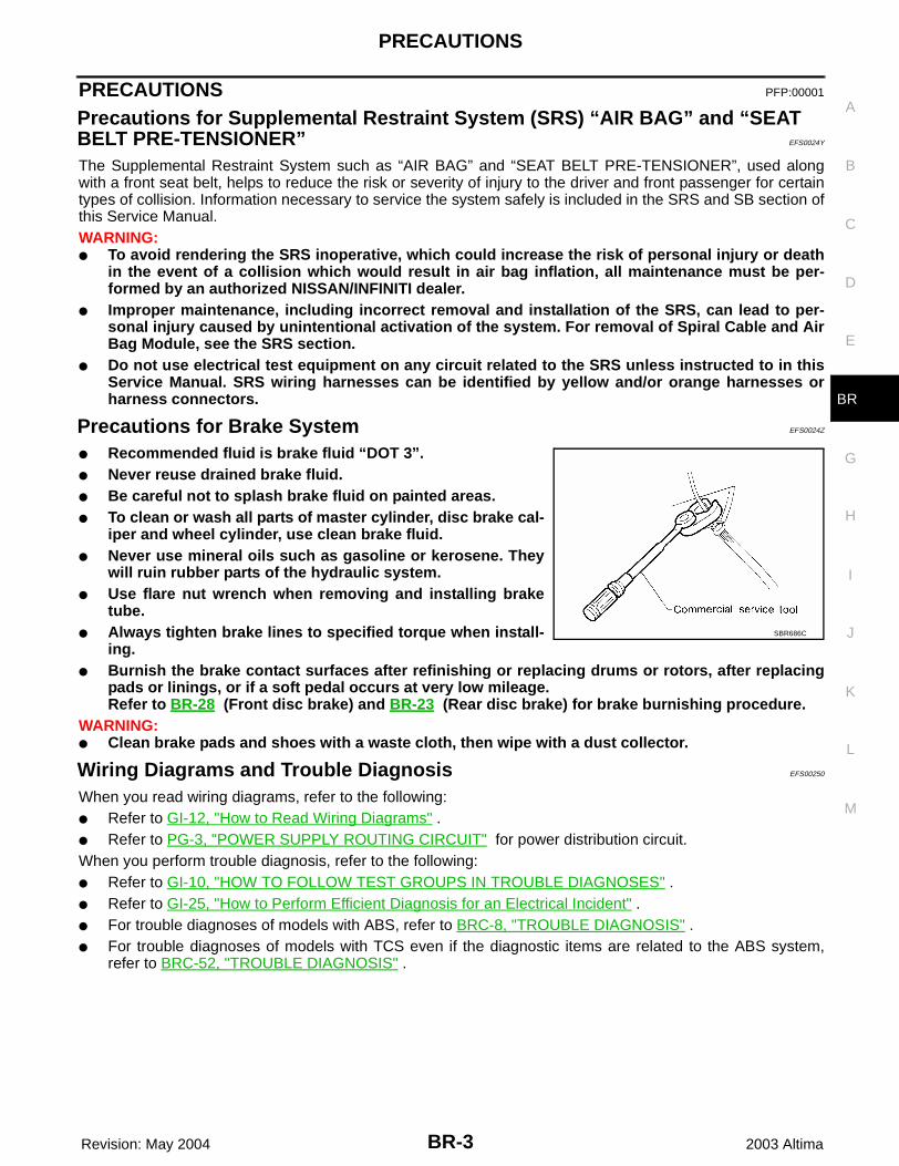
Precautions for Brake System EFS0024Z
● Recommended fluid is brake fluid “DOT 3”.● Never reuse drained brake fluid.● Be careful not to splash brake fluid on painted areas.● To clean or wash all parts of master cylinder, disc brake cal-
iper and wheel cylinder, use clean brake fluid.● Never use mineral oils such as gasoline or kerosene. They
will ruin rubber parts of the hydraulic system.● Use flare nut wrench when removing and installing brake
tube.● Always tighten brake lines to specified torque when install-
ing.● Burnish the brake contact surfaces after refinishing or replacing drums or rotors, after replacing
pads or linings, or if a soft pedal occurs at very low mileage.Refer to BR-28 (Front disc brake) and BR-23 (Rear disc brake) for brake burnishing procedure.
WARNING:● Clean brake pads and shoes with a waste cloth, then wipe with a dust collector.
Wiring Diagrams and Trouble Diagnosis EFS00250
When you read wiring diagrams, refer to the following:● Refer to GI-12, "How to Read Wiring Diagrams" .● Refer to PG-3, "POWER SUPPLY ROUTING CIRCUIT" for power distribution circuit.When you perform trouble diagnosis, refer to the following:● Refer to GI-10, "HOW TO FOLLOW TEST GROUPS IN TROUBLE DIAGNOSES" .● Refer to GI-25, "How to Perform Efficient Diagnosis for an Electrical Incident" .● For trouble diagnoses of models with ABS, refer to BRC-8, "TROUBLE DIAGNOSIS" .● For trouble diagnoses of models with TCS even if the diagnostic items are related to the ABS system,
refer to BRC-52, "TROUBLE DIAGNOSIS" .
SBR686C
BR-4
PREPARATION
Revision: May 2004 2003 Altima
PREPARATION PFP:00002
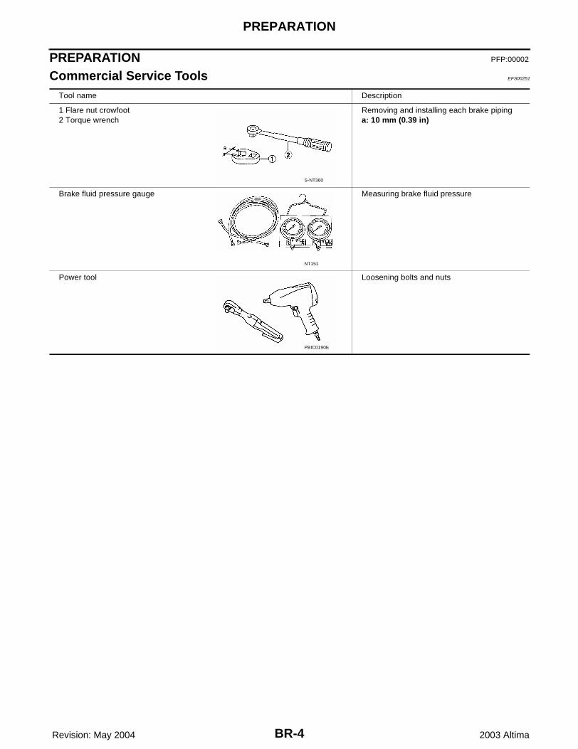
Commercial Service Tools EFS00251
Tool name Description
1 Flare nut crowfoot2 Torque wrench
Removing and installing each brake pipinga: 10 mm (0.39 in)
Brake fluid pressure gauge Measuring brake fluid pressure
Power tool Loosening bolts and nuts
S-NT360
NT151
PBIC0190E
NOISE, VIBRATION, AND HARSHNESS (NVH) TROUBLESHOOTING
BR-5
C
D
E
G
H
I
J
K
L
M
A
B
BR
Revision: May 2004 2003 Altima
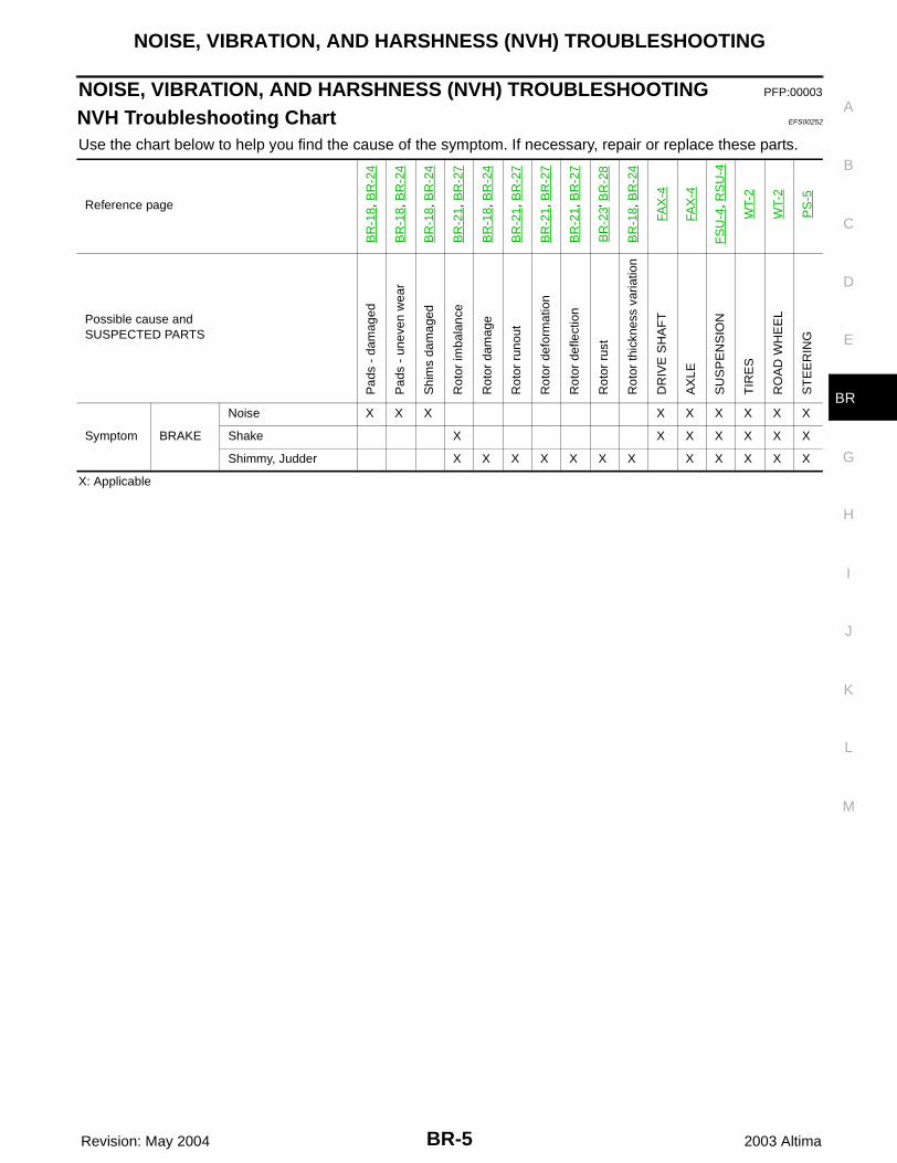
NOISE, VIBRATION, AND HARSHNESS (NVH) TROUBLESHOOTING PFP:00003
NVH Troubleshooting Chart EFS00252
Use the chart below to help you find the cause of the symptom. If necessary, repair or replace these parts.
X: Applicable
Reference page
BR
-18,
BR
-24
BR
-18,
BR
-24
BR
-18,
BR
-24
BR
-21,
BR
-27
BR
-18,
BR
-24
BR
-21,
BR
-27
BR
-21,
BR
-27
BR
-21,
BR
-27
BR
-23'
BR
-28
BR
-18,
BR
-24
FAX
-4
FAX
-4
FS
U-4
, RS
U-4
WT-
2
WT-
2
PS
-5
Possible cause andSUSPECTED PARTS
Pad
s -
dam
aged
Pad
s -
unev
en w
ear
Shi
ms
dam
aged
Rot
or im
bala
nce
Rot
or d
amag
e
Rot
or r
unou
t
Rot
or d
efor
mat
ion
Rot
or d
efle
ctio
n
Rot
or r
ust
Rot
or th
ickn
ess
varia
tion
DR
IVE
SH
AF
T
AX
LE
SU
SP
EN
SIO
N
TIR
ES
RO
AD
WH
EE
L
ST
EE
RIN
G
Symptom BRAKE
Noise X X X X X X X X X
Shake X X X X X X X
Shimmy, Judder X X X X X X X X X X X X
BR-6
BRAKE PEDAL
Revision: May 2004 2003 Altima
BRAKE PEDAL PFP:46501
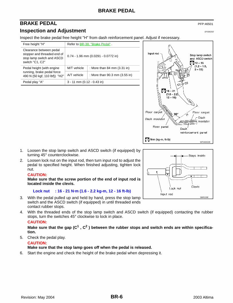
Inspection and Adjustment EFS00253
Inspect the brake pedal free height "H" from dash reinforcement panel. Adjust if necessary.
1. Loosen the stop lamp switch and ASCD switch (if equipped) byturning 45° counterclockwise.
2. Loosen lock nut on the input rod, then turn input rod to adjust thepedal to specified height. When finished adjusting, tighten locknut.CAUTION:Make sure that the screw portion of the end of input rod islocated inside the clevis.
3. With the pedal pulled up and held by hand, press the stop lampswitch and the ASCD switch (if equipped) in until threaded endscontact rubber stops.
4. With the threaded ends of the stop lamp switch and ASCD switch (if equipped) contacting the rubberstops, turn the switches 45° clockwise to lock in place.CAUTION:Make sure that the gap (C1 , C2 ) between the rubber stops and switch ends are within specifica-tion.
5. Check the pedal play.CAUTION:Make sure that the stop lamp goes off when the pedal is released.
6. Start the engine and check the height of the brake pedal when depressing it.
Free height "H" Refer to BR-30, "Brake Pedal" .
Clearance between pedal stopper and threaded end of stop lamp switch and ASCD switch "C1, C2"
0.74 - 1.96 mm (0.0291 - 0.0772 in)
Pedal height (with engine running, brake pedal force 490 N {50 kgf, 110 lbf}) "H2"
M/T vehicle : More than 84 mm (3.31 in)
A/T vehicle : More than 90.3 mm (3.55 in)
Pedal play "A" 3 - 11 mm (0.12 - 0.43 in)
WFIA0022E
Lock nut : 16 - 21 N·m (1.6 - 2.2 kg-m, 12 - 16 ft-lb)SBR229E
BRAKE PEDAL
BR-7
C
D
E
G
H
I
J
K
L
M
A
B
BR
Revision: May 2004 2003 Altima
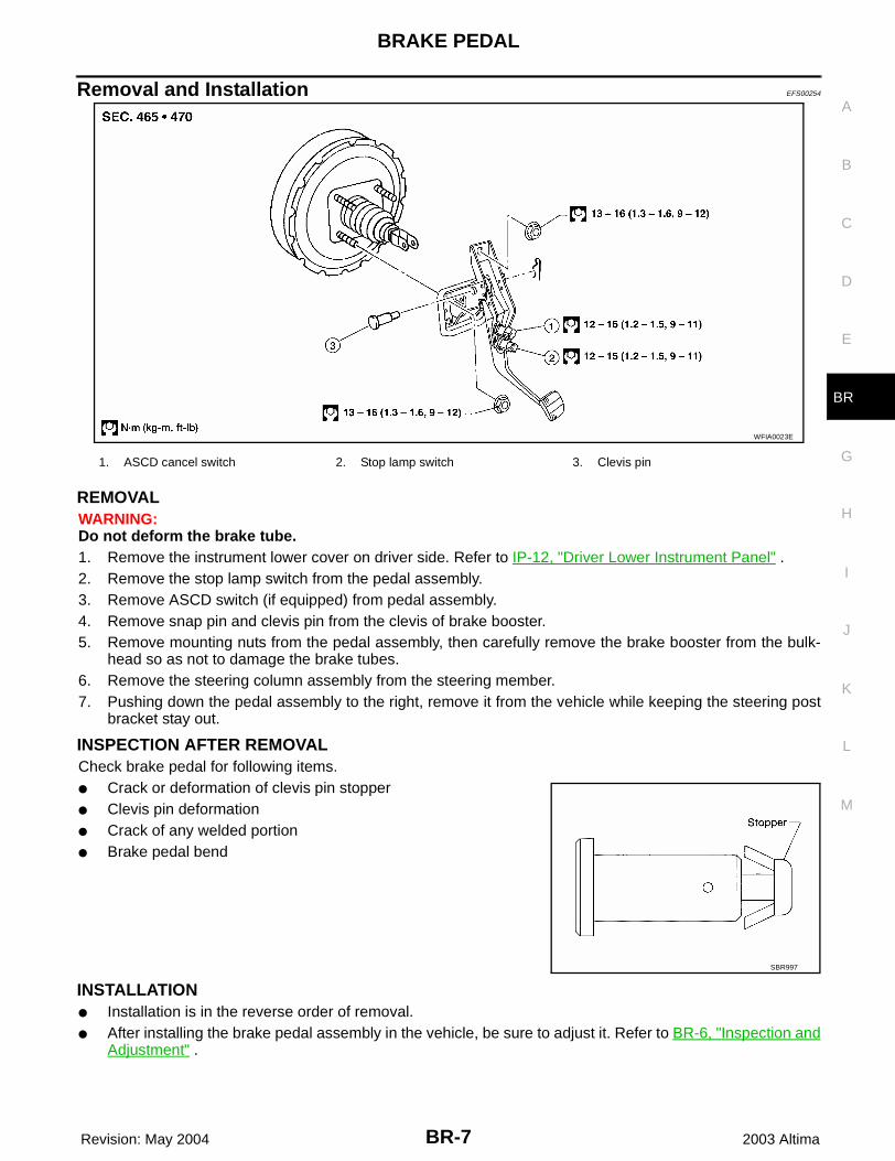
Removal and Installation EFS00254
REMOVAL WARNING:Do not deform the brake tube. 1. Remove the instrument lower cover on driver side. Refer to IP-12, "Driver Lower Instrument Panel" .2. Remove the stop lamp switch from the pedal assembly.3. Remove ASCD switch (if equipped) from pedal assembly.4. Remove snap pin and clevis pin from the clevis of brake booster.5. Remove mounting nuts from the pedal assembly, then carefully remove the brake booster from the bulk-
head so as not to damage the brake tubes.6. Remove the steering column assembly from the steering member.7. Pushing down the pedal assembly to the right, remove it from the vehicle while keeping the steering post
bracket stay out.
INSPECTION AFTER REMOVALCheck brake pedal for following items.● Crack or deformation of clevis pin stopper● Clevis pin deformation● Crack of any welded portion● Brake pedal bend
INSTALLATION ● Installation is in the reverse order of removal.● After installing the brake pedal assembly in the vehicle, be sure to adjust it. Refer to BR-6, "Inspection and
Adjustment" .
WFIA0023E
1. ASCD cancel switch 2. Stop lamp switch 3. Clevis pin
SBR997
BR-8
BRAKE FLUID
Revision: May 2004 2003 Altima
BRAKE FLUID PFP:KN100
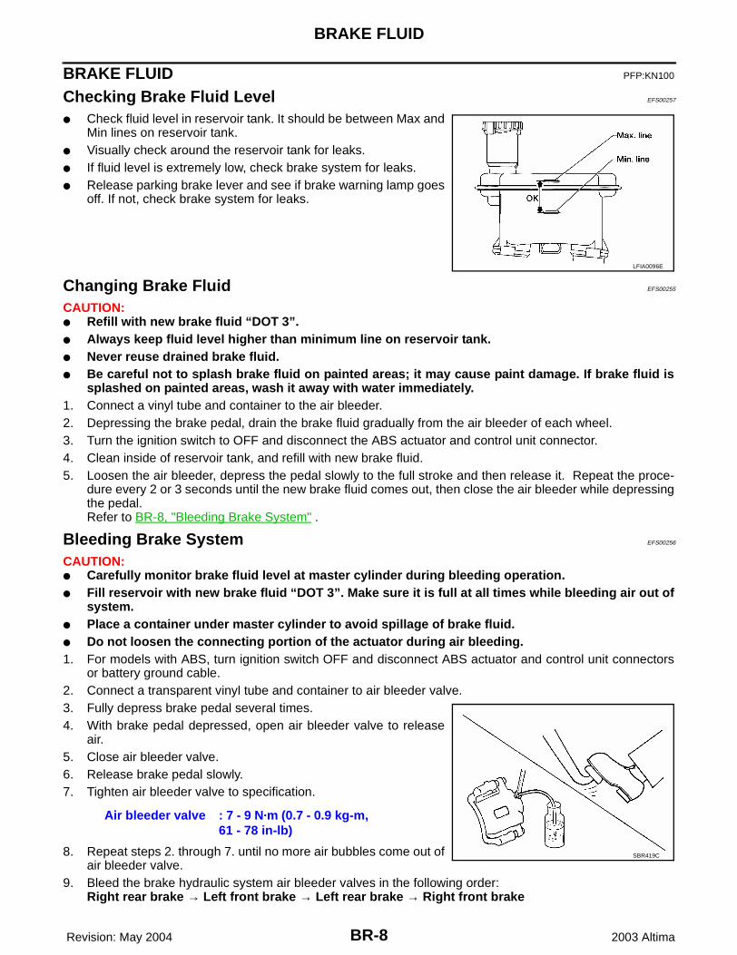
Checking Brake Fluid Level EFS00257
● Check fluid level in reservoir tank. It should be between Max andMin lines on reservoir tank.
● Visually check around the reservoir tank for leaks.● If fluid level is extremely low, check brake system for leaks.● Release parking brake lever and see if brake warning lamp goes
off. If not, check brake system for leaks.
Changing Brake Fluid EFS00255
CAUTION:● Refill with new brake fluid “DOT 3”.● Always keep fluid level higher than minimum line on reservoir tank.● Never reuse drained brake fluid.● Be careful not to splash brake fluid on painted areas; it may cause paint damage. If brake fluid is
splashed on painted areas, wash it away with water immediately.1. Connect a vinyl tube and container to the air bleeder.2. Depressing the brake pedal, drain the brake fluid gradually from the air bleeder of each wheel. 3. Turn the ignition switch to OFF and disconnect the ABS actuator and control unit connector.4. Clean inside of reservoir tank, and refill with new brake fluid.5. Loosen the air bleeder, depress the pedal slowly to the full stroke and then release it. Repeat the proce-
dure every 2 or 3 seconds until the new brake fluid comes out, then close the air bleeder while depressingthe pedal.Refer to BR-8, "Bleeding Brake System" .
Bleeding Brake System EFS00256
CAUTION:● Carefully monitor brake fluid level at master cylinder during bleeding operation.● Fill reservoir with new brake fluid “DOT 3”. Make sure it is full at all times while bleeding air out of
system.● Place a container under master cylinder to avoid spillage of brake fluid.● Do not loosen the connecting portion of the actuator during air bleeding.1. For models with ABS, turn ignition switch OFF and disconnect ABS actuator and control unit connectors
or battery ground cable.2. Connect a transparent vinyl tube and container to air bleeder valve.3. Fully depress brake pedal several times.4. With brake pedal depressed, open air bleeder valve to release
air.5. Close air bleeder valve.6. Release brake pedal slowly.7. Tighten air bleeder valve to specification.
8. Repeat steps 2. through 7. until no more air bubbles come out ofair bleeder valve.
9. Bleed the brake hydraulic system air bleeder valves in the following order:Right rear brake → Left front brake → Left rear brake → Right front brake
LFIA0096E
Air bleeder valve : 7 - 9 N·m (0.7 - 0.9 kg-m, 61 - 78 in-lb)
SBR419C
BRAKE PIPING AND HOSE
BR-9
C
D
E
G
H
I
J
K
L
M
A
B
BR
Revision: May 2004 2003 Altima
BRAKE PIPING AND HOSE PFP:46210
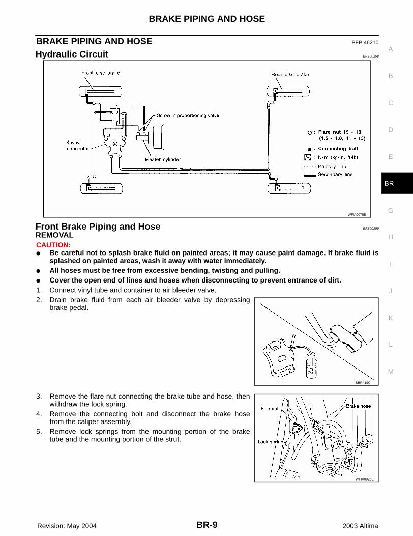
Hydraulic Circuit EFS00258
Front Brake Piping and Hose EFS00259
REMOVALCAUTION:● Be careful not to splash brake fluid on painted areas; it may cause paint damage. If brake fluid is
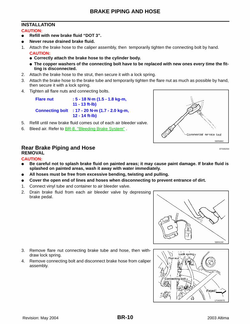
splashed on painted areas, wash it away with water immediately.● All hoses must be free from excessive bending, twisting and pulling.● Cover the open end of lines and hoses when disconnecting to prevent entrance of dirt.1. Connect vinyl tube and container to air bleeder valve.2. Drain brake fluid from each air bleeder valve by depressing
brake pedal.
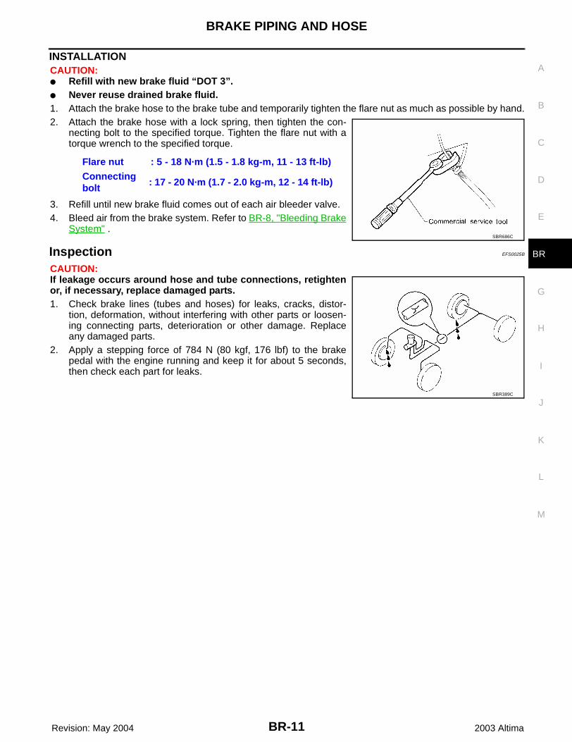
3. Remove the flare nut connecting the brake tube and hose, thenwithdraw the lock spring.
4. Remove the connecting bolt and disconnect the brake hosefrom the caliper assembly.
5. Remove lock springs from the mounting portion of the braketube and the mounting portion of the strut.
WFIA0075E
SBR419C
WFIA0025E
BR-10
BRAKE PIPING AND HOSE
Revision: May 2004 2003 Altima
INSTALLATIONCAUTION:● Refill with new brake fluid “DOT 3”.● Never reuse drained brake fluid.1. Attach the brake hose to the caliper assembly, then temporarily tighten the connecting bolt by hand.
CAUTION:● Correctly attach the brake hose to the cylinder body. ● The copper washers of the connecting bolt have to be replaced with new ones every time the fit-
ting is disconnected. 2. Attach the brake hose to the strut, then secure it with a lock spring.3. Attach the brake hose to the brake tube and temporarily tighten the flare nut as much as possible by hand,
then secure it with a lock spring.4. Tighten all flare nuts and connecting bolts.
5. Refill until new brake fluid comes out of each air bleeder valve.6. Bleed air. Refer to BR-8, "Bleeding Brake System" .
Rear Brake Piping and Hose EFS0025A
REMOVAL CAUTION:● Be careful not to splash brake fluid on painted areas; it may cause paint damage. If brake fluid is
splashed on painted areas, wash it away with water immediately.● All hoses must be free from excessive bending, twisting and pulling.● Cover the open end of lines and hoses when disconnecting to prevent entrance of dirt.1. Connect vinyl tube and container to air bleeder valve.2. Drain brake fluid from each air bleeder valve by depressing
brake pedal.
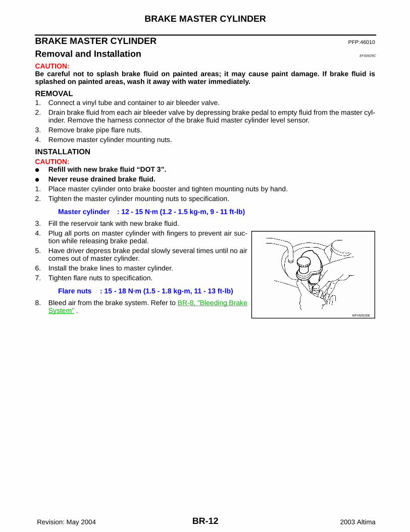
3. Remove flare nut connecting brake tube and hose, then with-draw lock spring.
4. Remove connecting bolt and disconnect brake hose from caliperassembly.
Flare nut : 5 - 18 N·m (1.5 - 1.8 kg-m, 11 - 13 ft-lb)
Connecting bolt : 17 - 20 N·m (1.7 - 2.0 kg-m, 12 - 14 ft-lb)
SBR686C
SBR419C
LFIA0097E
BRAKE PIPING AND HOSE
BR-11
C
D
E
G
H
I
J
K
L
M
A
B
BR
Revision: May 2004 2003 Altima
INSTALLATIONCAUTION:● Refill with new brake fluid “DOT 3”.● Never reuse drained brake fluid.1. Attach the brake hose to the brake tube and temporarily tighten the flare nut as much as possible by hand.2. Attach the brake hose with a lock spring, then tighten the con-
necting bolt to the specified torque. Tighten the flare nut with atorque wrench to the specified torque.
3. Refill until new brake fluid comes out of each air bleeder valve.4. Bleed air from the brake system. Refer to BR-8, "Bleeding Brake
System" .
Inspection EFS0025B
CAUTION:If leakage occurs around hose and tube connections, retightenor, if necessary, replace damaged parts.1. Check brake lines (tubes and hoses) for leaks, cracks, distor-
tion, deformation, without interfering with other parts or loosen-ing connecting parts, deterioration or other damage. Replaceany damaged parts.
2. Apply a stepping force of 784 N (80 kgf, 176 lbf) to the brakepedal with the engine running and keep it for about 5 seconds,then check each part for leaks.
Flare nut : 5 - 18 N·m (1.5 - 1.8 kg-m, 11 - 13 ft-lb)Connecting bolt
: 17 - 20 N·m (1.7 - 2.0 kg-m, 12 - 14 ft-lb)
SBR686C
SBR389C
BR-12
BRAKE MASTER CYLINDER
Revision: May 2004 2003 Altima
BRAKE MASTER CYLINDER PFP:46010
Removal and Installation EFS0025C
CAUTION:Be careful not to splash brake fluid on painted areas; it may cause paint damage. If brake fluid issplashed on painted areas, wash it away with water immediately.
REMOVAL1. Connect a vinyl tube and container to air bleeder valve.2. Drain brake fluid from each air bleeder valve by depressing brake pedal to empty fluid from the master cyl-
inder. Remove the harness connector of the brake fluid master cylinder level sensor.3. Remove brake pipe flare nuts.4. Remove master cylinder mounting nuts.
INSTALLATIONCAUTION:● Refill with new brake fluid “DOT 3”.● Never reuse drained brake fluid.1. Place master cylinder onto brake booster and tighten mounting nuts by hand.2. Tighten the master cylinder mounting nuts to specification.
3. Fill the reservoir tank with new brake fluid.4. Plug all ports on master cylinder with fingers to prevent air suc-
tion while releasing brake pedal.5. Have driver depress brake pedal slowly several times until no air
comes out of master cylinder.6. Install the brake lines to master cylinder.7. Tighten flare nuts to specification.
8. Bleed air from the brake system. Refer to BR-8, "Bleeding BrakeSystem" .
Master cylinder : 12 - 15 N·m (1.2 - 1.5 kg-m, 9 - 11 ft-lb)
Flare nuts : 15 - 18 N·m (1.5 - 1.8 kg-m, 11 - 13 ft-lb)
WFIA0026E
BRAKE MASTER CYLINDER
BR-13
C
D
E
G
H
I
J
K
L
M
A
B
BR
Revision: May 2004 2003 Altima
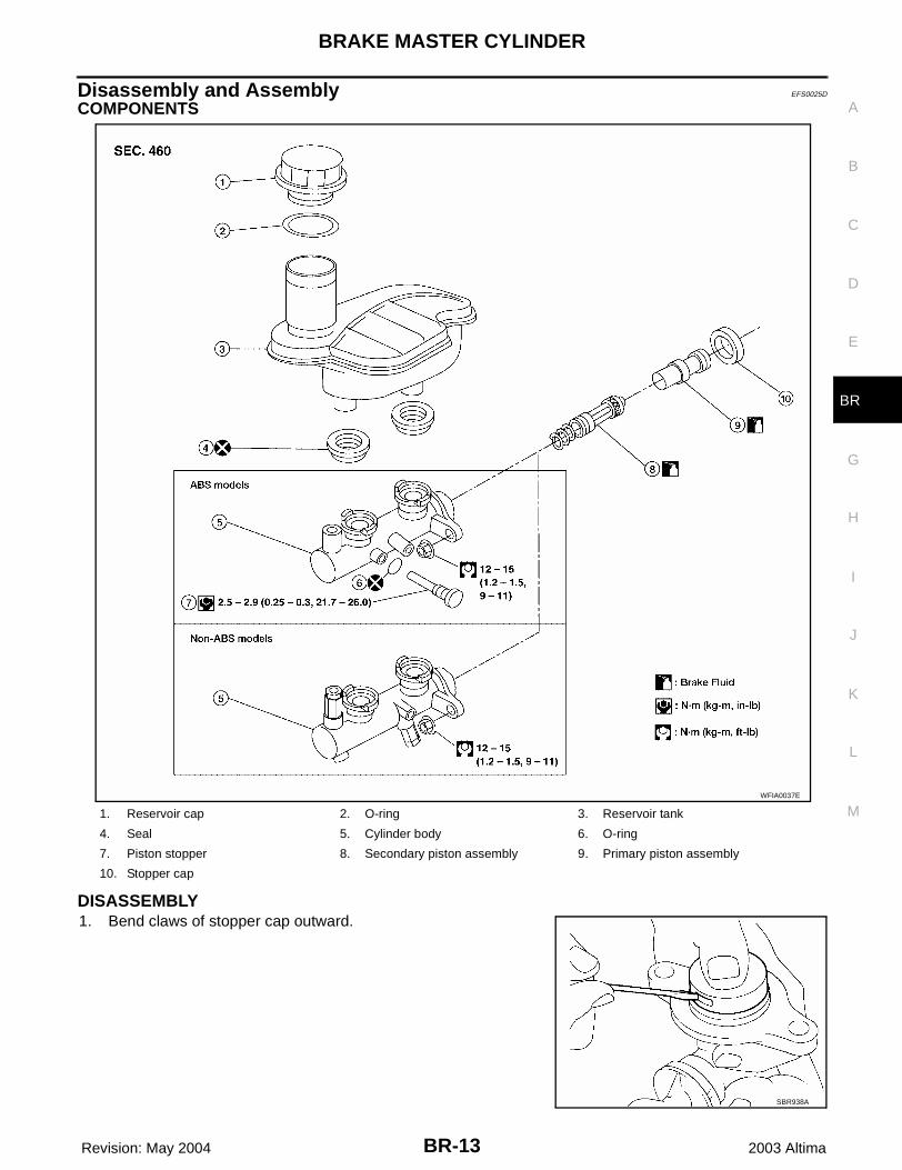
Disassembly and Assembly EFS0025D
COMPONENTS
DISASSEMBLY1. Bend claws of stopper cap outward.
1. Reservoir cap 2. O-ring 3. Reservoir tank
4. Seal 5. Cylinder body 6. O-ring
7. Piston stopper 8. Secondary piston assembly 9. Primary piston assembly
10. Stopper cap
WFIA0037E
SBR938A
BR-14
BRAKE MASTER CYLINDER
Revision: May 2004 2003 Altima
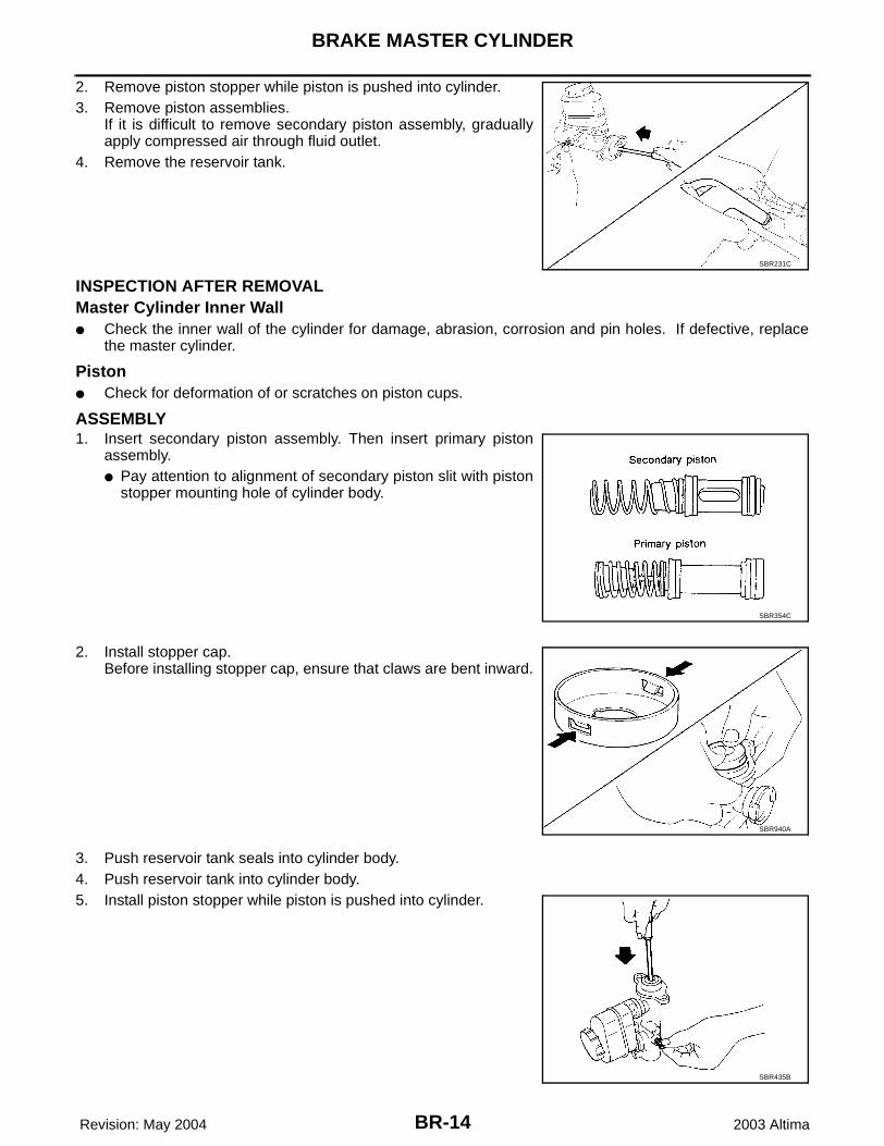
2. Remove piston stopper while piston is pushed into cylinder.3. Remove piston assemblies.
If it is difficult to remove secondary piston assembly, graduallyapply compressed air through fluid outlet.
4. Remove the reservoir tank.
INSPECTION AFTER REMOVALMaster Cylinder Inner Wall● Check the inner wall of the cylinder for damage, abrasion, corrosion and pin holes. If defective, replace
the master cylinder.
Piston● Check for deformation of or scratches on piston cups.
ASSEMBLY1. Insert secondary piston assembly. Then insert primary piston
assembly.● Pay attention to alignment of secondary piston slit with piston
stopper mounting hole of cylinder body.
2. Install stopper cap.Before installing stopper cap, ensure that claws are bent inward.
3. Push reservoir tank seals into cylinder body.4. Push reservoir tank into cylinder body.5. Install piston stopper while piston is pushed into cylinder.
SBR231C
SBR354C
SBR940A
SBR435B
BRAKE BOOSTER
BR-15
C
D
E
G
H
I
J
K
L
M
A
B
BR
Revision: May 2004 2003 Altima
BRAKE BOOSTER PFP:47200
On-vehicle Service EFS0025E
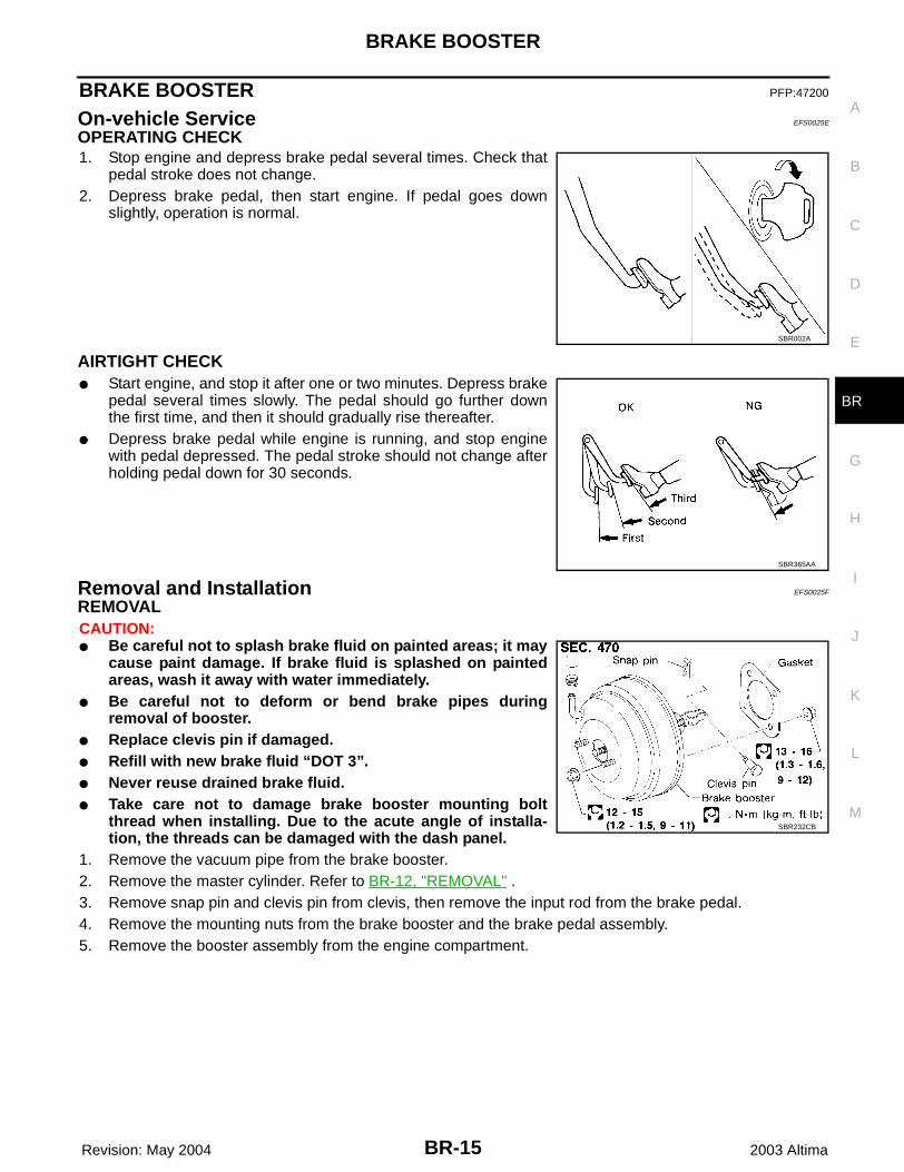
OPERATING CHECK 1. Stop engine and depress brake pedal several times. Check that
pedal stroke does not change.2. Depress brake pedal, then start engine. If pedal goes down
slightly, operation is normal.
AIRTIGHT CHECK ● Start engine, and stop it after one or two minutes. Depress brake
pedal several times slowly. The pedal should go further downthe first time, and then it should gradually rise thereafter.
● Depress brake pedal while engine is running, and stop enginewith pedal depressed. The pedal stroke should not change afterholding pedal down for 30 seconds.
Removal and Installation EFS0025F
REMOVALCAUTION:● Be careful not to splash brake fluid on painted areas; it may
cause paint damage. If brake fluid is splashed on paintedareas, wash it away with water immediately.
● Be careful not to deform or bend brake pipes duringremoval of booster.
● Replace clevis pin if damaged.● Refill with new brake fluid “DOT 3”.● Never reuse drained brake fluid.● Take care not to damage brake booster mounting bolt
thread when installing. Due to the acute angle of installa-tion, the threads can be damaged with the dash panel.
1. Remove the vacuum pipe from the brake booster.2. Remove the master cylinder. Refer to BR-12, "REMOVAL" .3. Remove snap pin and clevis pin from clevis, then remove the input rod from the brake pedal.4. Remove the mounting nuts from the brake booster and the brake pedal assembly.5. Remove the booster assembly from the engine compartment.
SBR002A
SBR365AA
SBR232CB
BR-16
BRAKE BOOSTER
Revision: May 2004 2003 Altima
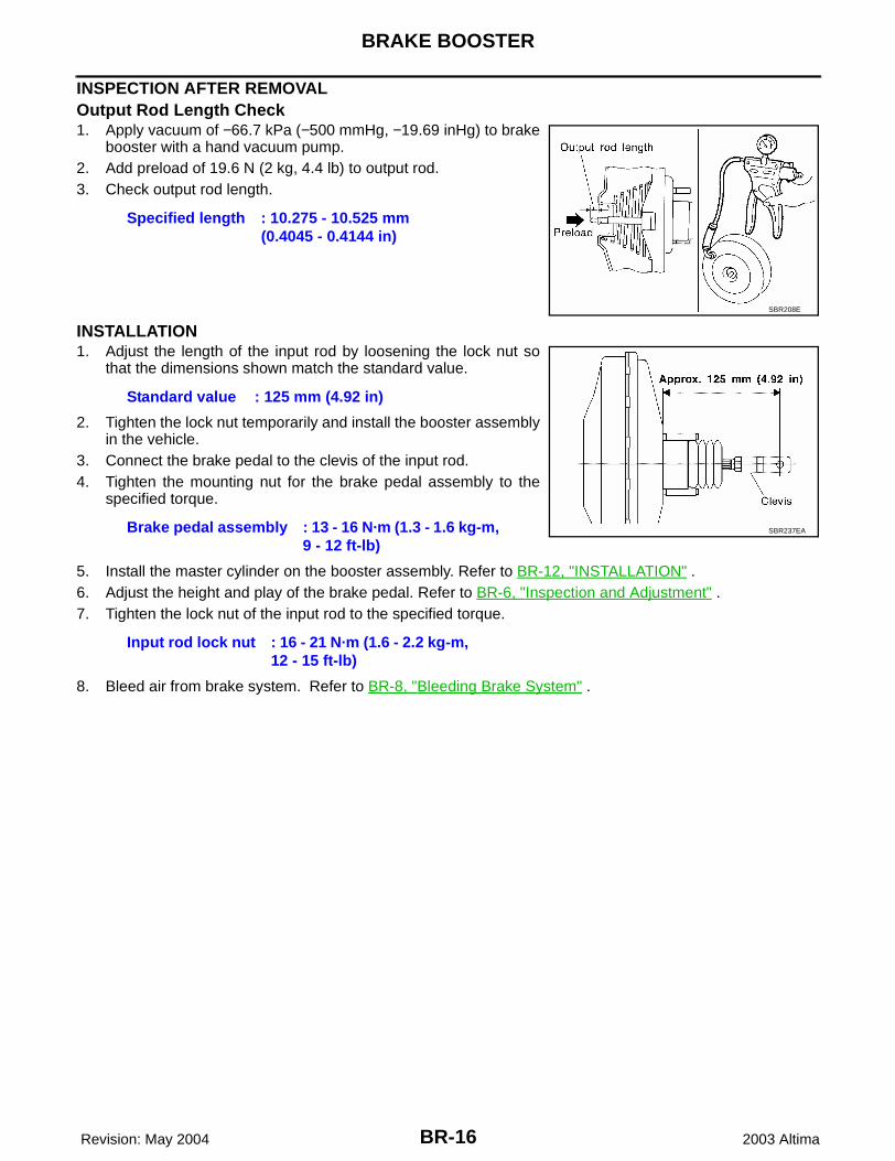
INSPECTION AFTER REMOVALOutput Rod Length Check1. Apply vacuum of −66.7 kPa (−500 mmHg, −19.69 inHg) to brake
booster with a hand vacuum pump.2. Add preload of 19.6 N (2 kg, 4.4 lb) to output rod.3. Check output rod length.
INSTALLATION 1. Adjust the length of the input rod by loosening the lock nut so
that the dimensions shown match the standard value.
2. Tighten the lock nut temporarily and install the booster assemblyin the vehicle.
3. Connect the brake pedal to the clevis of the input rod.4. Tighten the mounting nut for the brake pedal assembly to the
specified torque.
5. Install the master cylinder on the booster assembly. Refer to BR-12, "INSTALLATION" .6. Adjust the height and play of the brake pedal. Refer to BR-6, "Inspection and Adjustment" .7. Tighten the lock nut of the input rod to the specified torque.
8. Bleed air from brake system. Refer to BR-8, "Bleeding Brake System" .
Specified length : 10.275 - 10.525 mm (0.4045 - 0.4144 in)
SBR208E
Standard value : 125 mm (4.92 in)
Brake pedal assembly : 13 - 16 N·m (1.3 - 1.6 kg-m, 9 - 12 ft-lb)
Input rod lock nut : 16 - 21 N·m (1.6 - 2.2 kg-m, 12 - 15 ft-lb)
SBR237EA
VACUUM LINES
BR-17
C
D
E
G
H
I
J
K
L
M
A
B
BR
Revision: May 2004 2003 Altima
VACUUM LINES PFP:41920
Removal and Installation EFS0025G
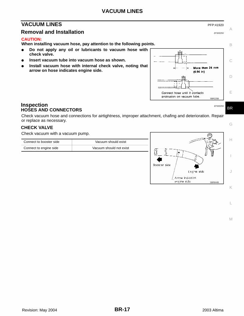
CAUTION:When installing vacuum hose, pay attention to the following points.● Do not apply any oil or lubricants to vacuum hose with
check valve.● Insert vacuum tube into vacuum hose as shown.● Install vacuum hose with internal check valve, noting that
arrow on hose indicates engine side.
Inspection EFS0025H
HOSES AND CONNECTORSCheck vacuum hose and connections for airtightness, improper attachment, chafing and deterioration. Repairor replace as necessary.
CHECK VALVECheck vacuum with a vacuum pump.
SBR225B
Connect to booster side Vacuum should exist
Connect to engine side Vacuum should not exist
SBR844B
BR-18
FRONT DISC BRAKE
Revision: May 2004 2003 Altima
FRONT DISC BRAKE PFP:41000
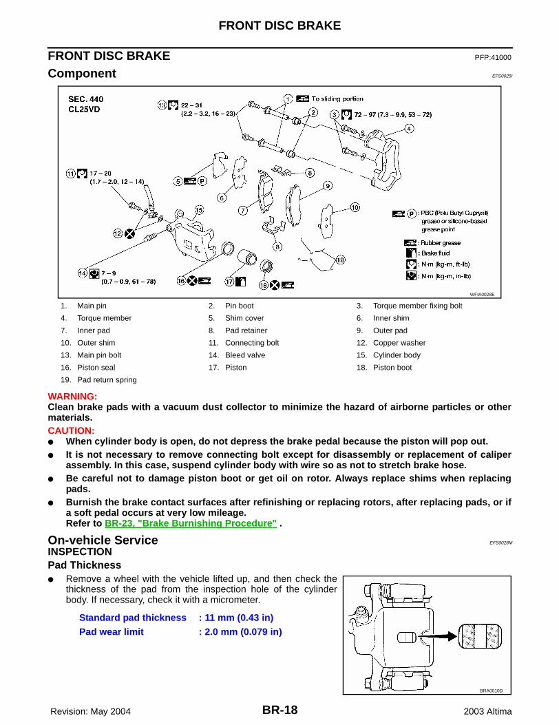
Component EFS0025I
WARNING:Clean brake pads with a vacuum dust collector to minimize the hazard of airborne particles or othermaterials.CAUTION:● When cylinder body is open, do not depress the brake pedal because the piston will pop out.● It is not necessary to remove connecting bolt except for disassembly or replacement of caliper
assembly. In this case, suspend cylinder body with wire so as not to stretch brake hose.● Be careful not to damage piston boot or get oil on rotor. Always replace shims when replacing
pads.● Burnish the brake contact surfaces after refinishing or replacing rotors, after replacing pads, or if
a soft pedal occurs at very low mileage.Refer to BR-23, "Brake Burnishing Procedure" .
On-vehicle Service EFS0028M
INSPECTIONPad Thickness● Remove a wheel with the vehicle lifted up, and then check the
thickness of the pad from the inspection hole of the cylinderbody. If necessary, check it with a micrometer.
1. Main pin 2. Pin boot 3. Torque member fixing bolt
4. Torque member 5. Shim cover 6. Inner shim
7. Inner pad 8. Pad retainer 9. Outer pad
10. Outer shim 11. Connecting bolt 12. Copper washer
13. Main pin bolt 14. Bleed valve 15. Cylinder body
16. Piston seal 17. Piston 18. Piston boot
19. Pad return spring
WFIA0028E
Standard pad thickness : 11 mm (0.43 in)Pad wear limit : 2.0 mm (0.079 in)
BRA0010D
FRONT DISC BRAKE
BR-19
C
D
E
G
H
I
J
K
L
M
A
B
BR
Revision: May 2004 2003 Altima
PAD REPLACEMENTRemoval● If shims are rusted or show peeling of the rubber coat, replace them with new shims.● Whenever the brake pads are replaced, the inner shim, the outer shim and the shim cover have to be
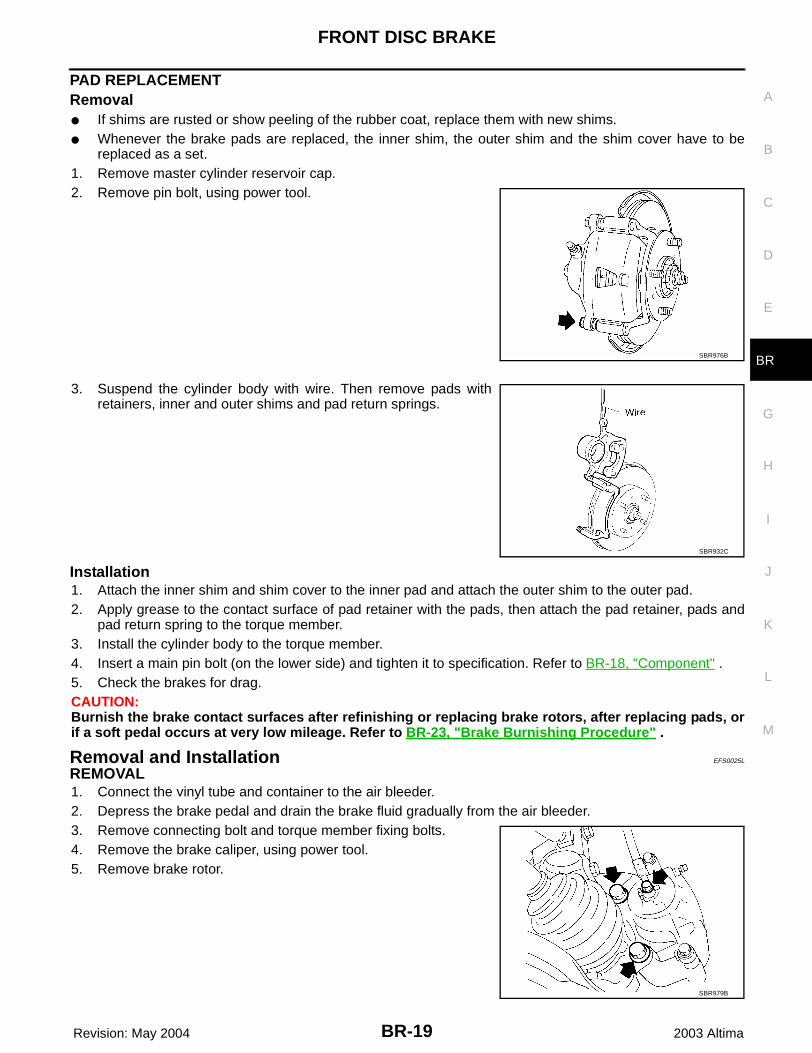
replaced as a set.1. Remove master cylinder reservoir cap.2. Remove pin bolt, using power tool.
3. Suspend the cylinder body with wire. Then remove pads withretainers, inner and outer shims and pad return springs.
Installation1. Attach the inner shim and shim cover to the inner pad and attach the outer shim to the outer pad.2. Apply grease to the contact surface of pad retainer with the pads, then attach the pad retainer, pads and
pad return spring to the torque member.3. Install the cylinder body to the torque member.4. Insert a main pin bolt (on the lower side) and tighten it to specification. Refer to BR-18, "Component" .5. Check the brakes for drag.CAUTION:Burnish the brake contact surfaces after refinishing or replacing brake rotors, after replacing pads, orif a soft pedal occurs at very low mileage. Refer to BR-23, "Brake Burnishing Procedure" .
Removal and Installation EFS0025L
REMOVAL1. Connect the vinyl tube and container to the air bleeder.2. Depress the brake pedal and drain the brake fluid gradually from the air bleeder.3. Remove connecting bolt and torque member fixing bolts.4. Remove the brake caliper, using power tool.5. Remove brake rotor.
SBR976B
SBR932C
SBR979B
BR-20
FRONT DISC BRAKE
Revision: May 2004 2003 Altima
INSTALLATIONCAUTION:● Refill with new brake fluid “DOT 3”.● Never reuse drained brake fluid.1. Install brake rotor.2. Install the brake caliper and tighten main pin bolt to specification. Refer to BR-18, "Component" .
CAUTION:When installing the caliper assembly in the vehicle, wipe oil from the seating surface of theknuckle spindle washer and the mounting surface of the caliper assembly.
3. Install brake hose to caliper and tighten connecting bolt to spec-ification. Refer to BR-18, "Component" .CAUTION:● The copper washer of the connecting bolt has to be
replaced every time the fitting is disconnected.● Correctly attach the brake hose to the projecting portion
of the cylinder body.4. Bleed air from brake system. Refer to BR-8, "Bleeding Brake
System" .CAUTION:Burnish the brake contact surfaces after refinishing or replac-ing brake rotors, after replacing pads, or if a soft pedal occurs at very low mileage. Refer to BR-23,"Brake Burnishing Procedure" .
Disassembly and Assembly EFS0025M
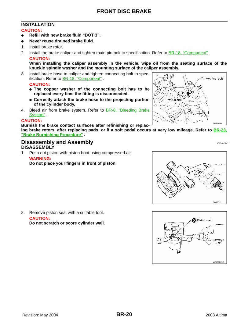
DISASSEMBLY1. Push out piston with piston boot using compressed air.
WARNING:Do not place your fingers in front of piston.
2. Remove piston seal with a suitable tool.CAUTION:Do not scratch or score cylinder wall.
SBR980B
SBR772
WFIA0029E
FRONT DISC BRAKE
BR-21
C
D
E
G
H
I
J
K
L
M
A
B
BR
Revision: May 2004 2003 Altima
INSPECTION AFTER DISASSEMBLYCaliper
CYLINDER BODYCAUTION:Use brake fluid to clean. Never use mineral oil.● Check inside surface of cylinder for score, rust, wear, damage or presence of foreign materials. If
any of the above conditions are observed, replace cylinder body.● Minor damage from rust or foreign materials may be eliminated by polishing surface with a fine
emery paper. Replace cylinder body if necessary.
TORQUE MEMBERCheck for wear, cracks or other damage. Replace if necessary.
PISTONCAUTION:Piston sliding surface is plated. Do not polish with emery paper even if rust or foreign materials arestuck to sliding surface.Check piston for score, rust, wear, damage or presence of foreign materials. Replace if any of the above con-ditions are observed.
SLIDE PIN, PIN BOLT AND PIN BOOTCheck for wear, cracks or other damage. Replace if any of the conditions are observed.
Rotor
VISUAL INSPECTIONCheck rotor for roughness, cracks or chips.
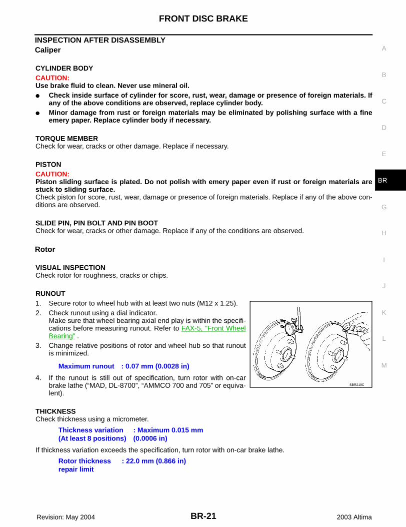
RUNOUT1. Secure rotor to wheel hub with at least two nuts (M12 x 1.25).2. Check runout using a dial indicator.
Make sure that wheel bearing axial end play is within the specifi-cations before measuring runout. Refer to FAX-5, "Front WheelBearing" .
3. Change relative positions of rotor and wheel hub so that runoutis minimized.
4. If the runout is still out of specification, turn rotor with on-carbrake lathe (“MAD, DL-8700”, “AMMCO 700 and 705” or equiva-lent).
THICKNESSCheck thickness using a micrometer.
If thickness variation exceeds the specification, turn rotor with on-car brake lathe.
Maximum runout : 0.07 mm (0.0028 in)
SBR219C
Thickness variation (At least 8 positions)
: Maximum 0.015 mm (0.0006 in)
Rotor thickness repair limit
: 22.0 mm (0.866 in)
BR-22
FRONT DISC BRAKE
Revision: May 2004 2003 Altima
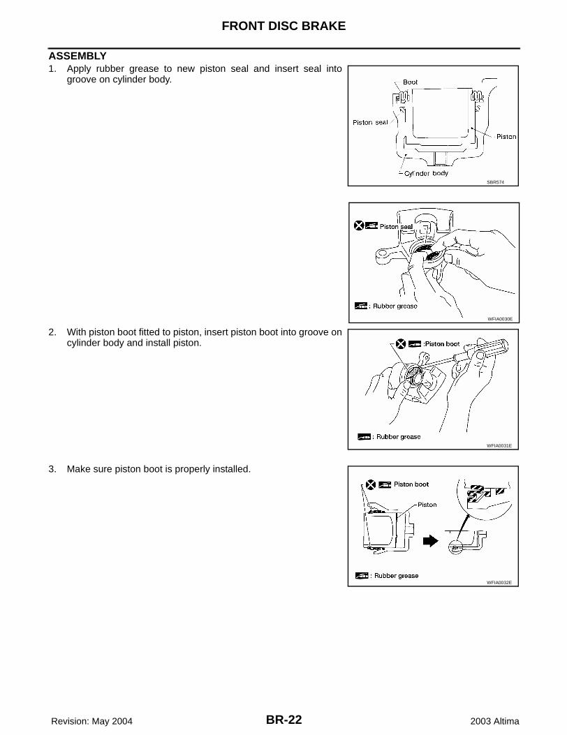
ASSEMBLY1. Apply rubber grease to new piston seal and insert seal into
groove on cylinder body.
2. With piston boot fitted to piston, insert piston boot into groove oncylinder body and install piston.
3. Make sure piston boot is properly installed.
SBR574
WFIA0030E
WFIA0031E
WFIA0032E
FRONT DISC BRAKE
BR-23
C
D
E
G
H
I
J
K
L
M
A
B
BR
Revision: May 2004 2003 Altima
Brake Burnishing Procedure EFS0025N
Burnish the brake contact surfaces according to the following procedure after refinishing or replacing brakerotors, after replacing pads or linings, or if a soft pedal occurs at very low mileage.CAUTION:Only perform this procedure under safe road and traffic conditions. Use extreme caution.1. Drive the vehicle on a straight smooth road at 50 km/h (31 MPH).2. Use medium brake pedal/foot effort to bring the vehicle to a complete stop from 50 km/h (31 MPH).
Adjust brake pedal/foot pressure so that vehicle stopping time equals 3 to 5 seconds.3. To cool the brake system, drive the vehicle at 50 km/h (31 MPH) for 1 minute without stopping.4. Repeat steps 1 to 3, 10 times or more to complete the burnishing procedure.
BR-24
REAR DISC BRAKE
Revision: May 2004 2003 Altima
REAR DISC BRAKE PFP:44000
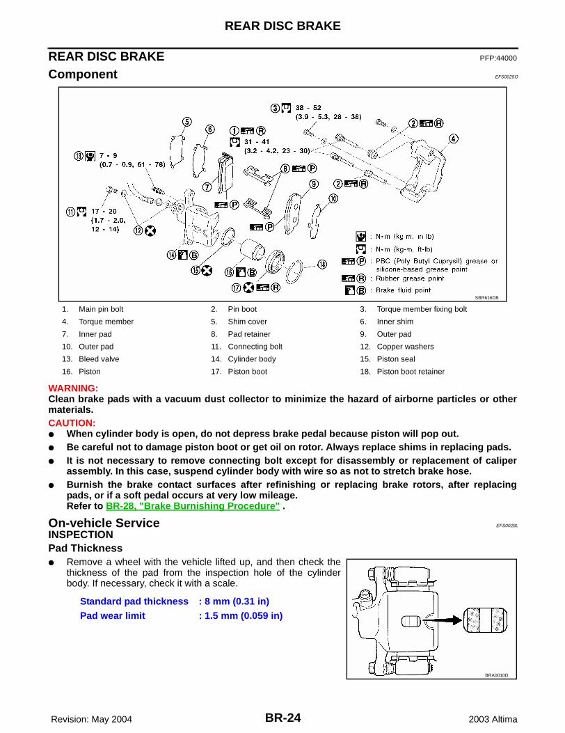
Component EFS0025O
WARNING:Clean brake pads with a vacuum dust collector to minimize the hazard of airborne particles or othermaterials.CAUTION:● When cylinder body is open, do not depress brake pedal because piston will pop out.● Be careful not to damage piston boot or get oil on rotor. Always replace shims in replacing pads.● It is not necessary to remove connecting bolt except for disassembly or replacement of caliper
assembly. In this case, suspend cylinder body with wire so as not to stretch brake hose.● Burnish the brake contact surfaces after refinishing or replacing brake rotors, after replacing
pads, or if a soft pedal occurs at very low mileage.Refer to BR-28, "Brake Burnishing Procedure" .
On-vehicle Service EFS0028L
INSPECTIONPad Thickness● Remove a wheel with the vehicle lifted up, and then check the
thickness of the pad from the inspection hole of the cylinderbody. If necessary, check it with a scale.
1. Main pin bolt 2. Pin boot 3. Torque member fixing bolt
4. Torque member 5. Shim cover 6. Inner shim
7. Inner pad 8. Pad retainer 9. Outer pad
10. Outer pad 11. Connecting bolt 12. Copper washers
13. Bleed valve 14. Cylinder body 15. Piston seal
16. Piston 17. Piston boot 18. Piston boot retainer
SBR616DB
Standard pad thickness : 8 mm (0.31 in)Pad wear limit : 1.5 mm (0.059 in)
BRA0010D
REAR DISC BRAKE
BR-25
C
D
E
G
H
I
J
K
L
M
A
B
BR
Revision: May 2004 2003 Altima
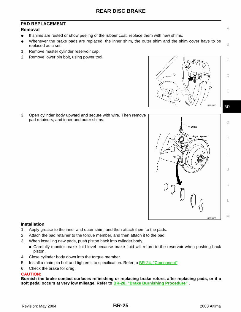
PAD REPLACEMENTRemoval● If shims are rusted or show peeling of the rubber coat, replace them with new shims.● Whenever the brake pads are replaced, the inner shim, the outer shim and the shim cover have to be
replaced as a set.1. Remove master cylinder reservoir cap.2. Remove lower pin bolt, using power tool.
3. Open cylinder body upward and secure with wire. Then removepad retainers, and inner and outer shims.
Installation1. Apply grease to the inner and outer shim, and then attach them to the pads.2. Attach the pad retainer to the torque member, and then attach it to the pad.3. When installing new pads, push piston back into cylinder body.
● Carefully monitor brake fluid level because brake fluid will return to the reservoir when pushing backpiston.
4. Close cylinder body down into the torque member.5. Install a main pin bolt and tighten it to specification. Refer to BR-24, "Component" .6. Check the brake for drag.CAUTION:Burnish the brake contact surfaces refinishing or replacing brake rotors, after replacing pads, or if asoft pedal occurs at very low mileage. Refer to BR-28, "Brake Burnishing Procedure" .
SBR090C
SBR042C
BR-26
REAR DISC BRAKE
Revision: May 2004 2003 Altima
Removal and Installation EFS0025R
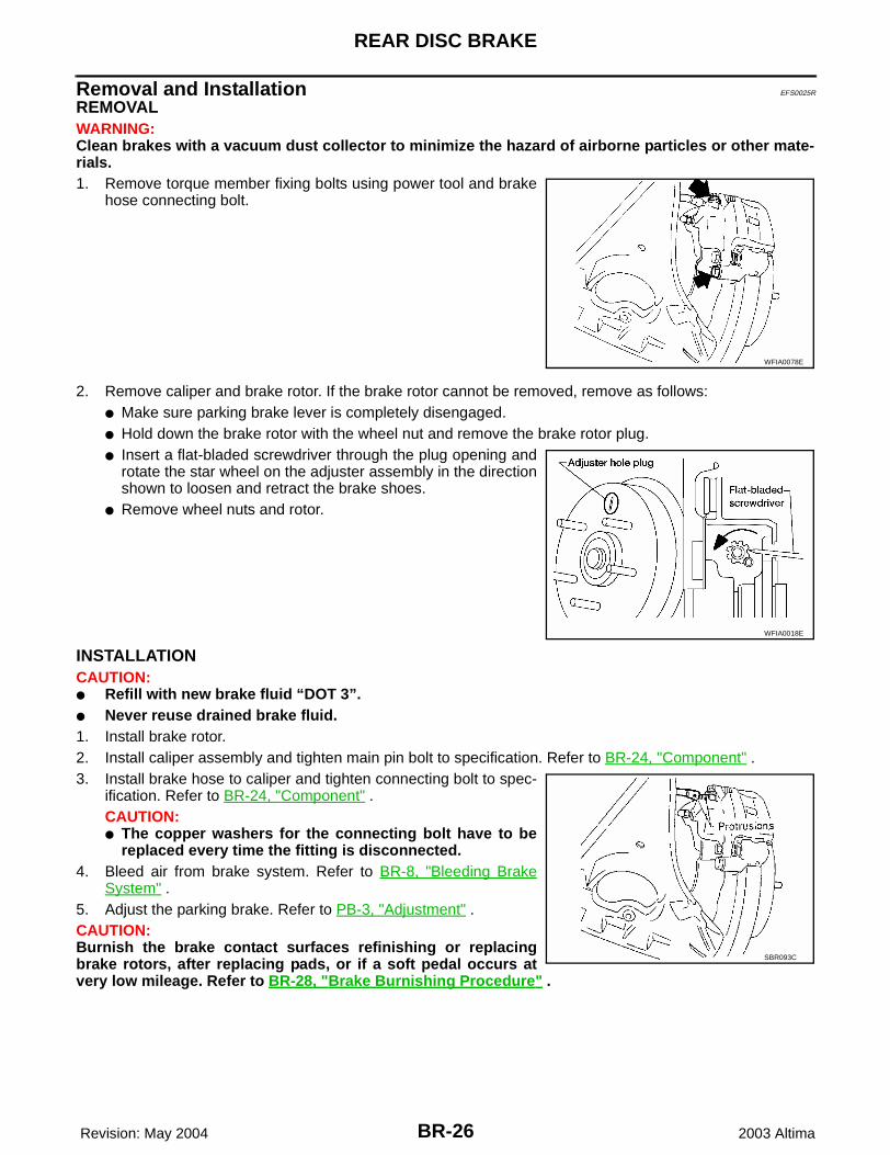
REMOVAL WARNING:Clean brakes with a vacuum dust collector to minimize the hazard of airborne particles or other mate-rials.1. Remove torque member fixing bolts using power tool and brake
hose connecting bolt.
2. Remove caliper and brake rotor. If the brake rotor cannot be removed, remove as follows:● Make sure parking brake lever is completely disengaged.● Hold down the brake rotor with the wheel nut and remove the brake rotor plug.● Insert a flat-bladed screwdriver through the plug opening and
rotate the star wheel on the adjuster assembly in the directionshown to loosen and retract the brake shoes.
● Remove wheel nuts and rotor.
INSTALLATIONCAUTION:● Refill with new brake fluid “DOT 3”.● Never reuse drained brake fluid.1. Install brake rotor.2. Install caliper assembly and tighten main pin bolt to specification. Refer to BR-24, "Component" .3. Install brake hose to caliper and tighten connecting bolt to spec-
ification. Refer to BR-24, "Component" .CAUTION:● The copper washers for the connecting bolt have to be
replaced every time the fitting is disconnected.4. Bleed air from brake system. Refer to BR-8, "Bleeding Brake
System" .5. Adjust the parking brake. Refer to PB-3, "Adjustment" .CAUTION:Burnish the brake contact surfaces refinishing or replacingbrake rotors, after replacing pads, or if a soft pedal occurs atvery low mileage. Refer to BR-28, "Brake Burnishing Procedure" .
WFIA0078E
WFIA0018E
SBR093C
REAR DISC BRAKE
BR-27
C
D
E
G
H
I
J
K
L
M
A
B
BR
Revision: May 2004 2003 Altima
Disassembly and Assembly EFS0025S
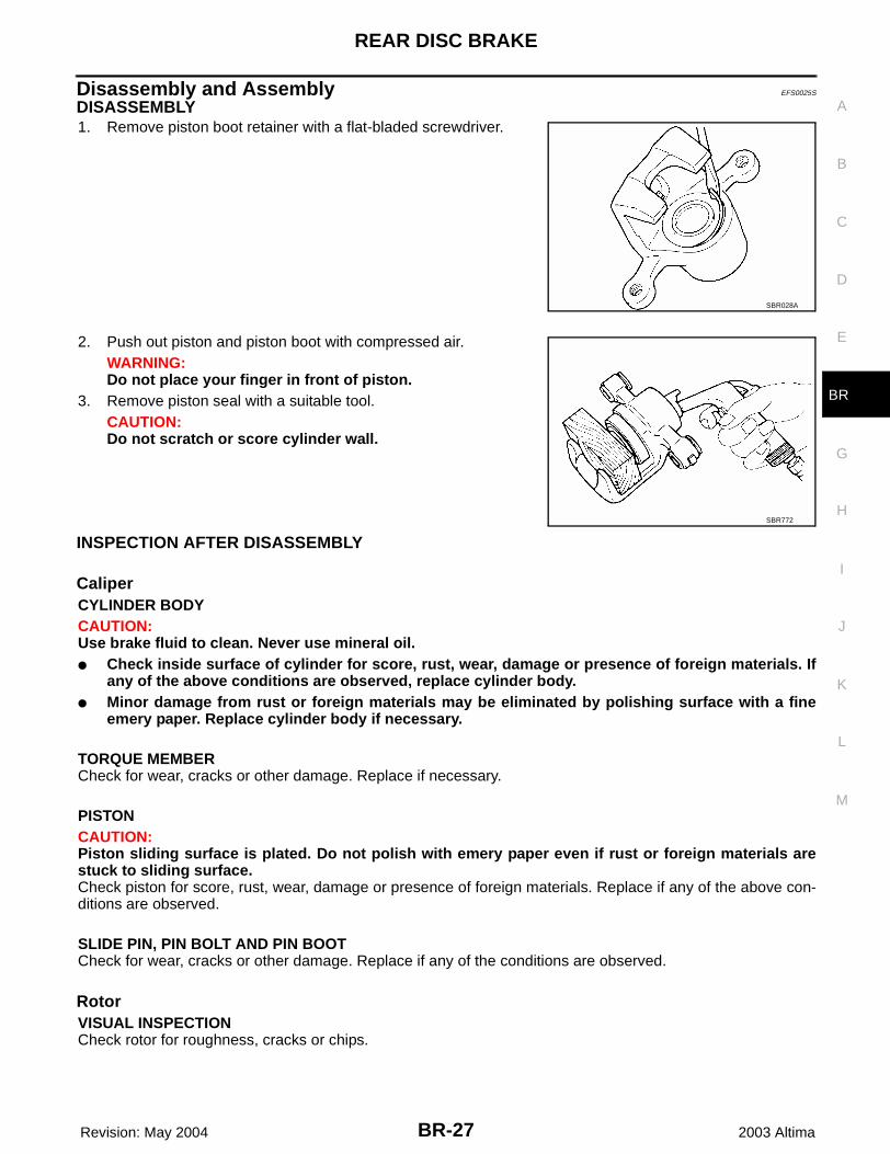
DISASSEMBLY1. Remove piston boot retainer with a flat-bladed screwdriver.
2. Push out piston and piston boot with compressed air.WARNING:Do not place your finger in front of piston.
3. Remove piston seal with a suitable tool.CAUTION:Do not scratch or score cylinder wall.
INSPECTION AFTER DISASSEMBLY
CaliperCYLINDER BODYCAUTION:Use brake fluid to clean. Never use mineral oil.● Check inside surface of cylinder for score, rust, wear, damage or presence of foreign materials. If
any of the above conditions are observed, replace cylinder body.● Minor damage from rust or foreign materials may be eliminated by polishing surface with a fine
emery paper. Replace cylinder body if necessary.
TORQUE MEMBERCheck for wear, cracks or other damage. Replace if necessary.
PISTONCAUTION:Piston sliding surface is plated. Do not polish with emery paper even if rust or foreign materials arestuck to sliding surface.Check piston for score, rust, wear, damage or presence of foreign materials. Replace if any of the above con-ditions are observed.
SLIDE PIN, PIN BOLT AND PIN BOOTCheck for wear, cracks or other damage. Replace if any of the conditions are observed.
RotorVISUAL INSPECTIONCheck rotor for roughness, cracks or chips.
SBR028A
SBR772
BR-28
REAR DISC BRAKE
Revision: May 2004 2003 Altima
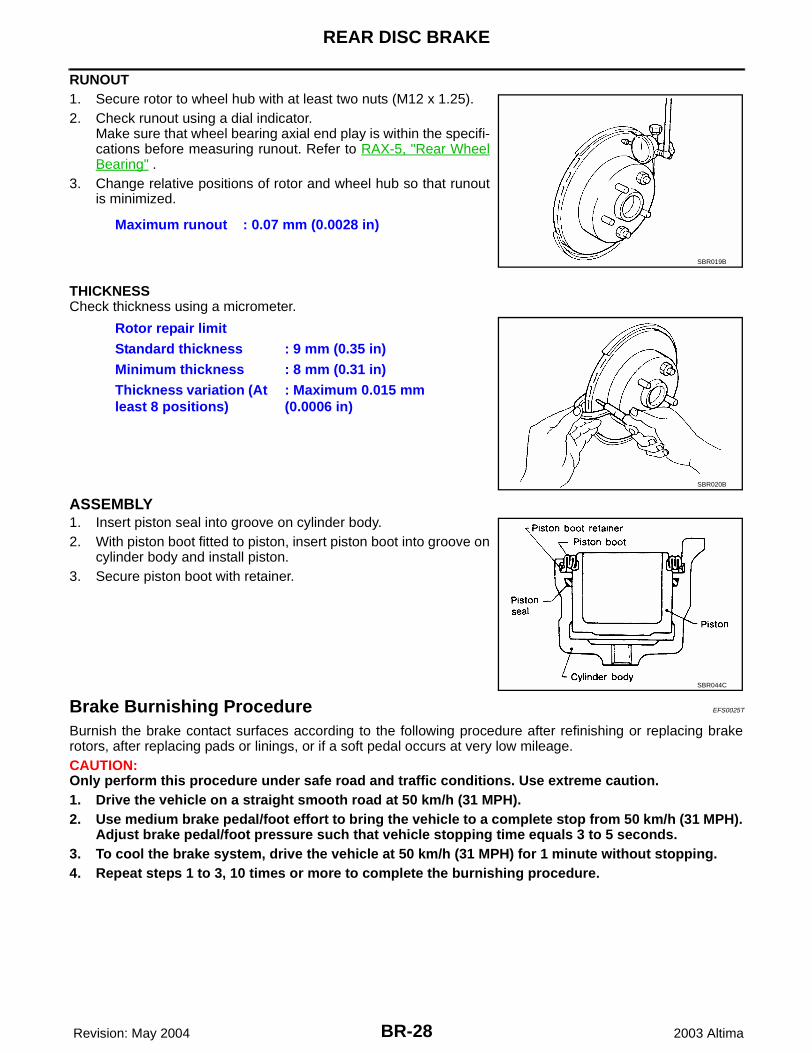
RUNOUT1. Secure rotor to wheel hub with at least two nuts (M12 x 1.25).2. Check runout using a dial indicator.
Make sure that wheel bearing axial end play is within the specifi-cations before measuring runout. Refer to RAX-5, "Rear WheelBearing" .
3. Change relative positions of rotor and wheel hub so that runoutis minimized.
THICKNESSCheck thickness using a micrometer.
ASSEMBLY 1. Insert piston seal into groove on cylinder body.2. With piston boot fitted to piston, insert piston boot into groove on
cylinder body and install piston.3. Secure piston boot with retainer.
Brake Burnishing Procedure EFS0025T
Burnish the brake contact surfaces according to the following procedure after refinishing or replacing brakerotors, after replacing pads or linings, or if a soft pedal occurs at very low mileage.CAUTION:Only perform this procedure under safe road and traffic conditions. Use extreme caution.1. Drive the vehicle on a straight smooth road at 50 km/h (31 MPH).2. Use medium brake pedal/foot effort to bring the vehicle to a complete stop from 50 km/h (31 MPH).
Adjust brake pedal/foot pressure such that vehicle stopping time equals 3 to 5 seconds.3. To cool the brake system, drive the vehicle at 50 km/h (31 MPH) for 1 minute without stopping.4. Repeat steps 1 to 3, 10 times or more to complete the burnishing procedure.
Maximum runout : 0.07 mm (0.0028 in)
SBR019B
Rotor repair limitStandard thickness : 9 mm (0.35 in)Minimum thickness : 8 mm (0.31 in)Thickness variation (At least 8 positions)
: Maximum 0.015 mm (0.0006 in)
SBR020B
SBR044C
DUAL PROPORTIONING VALVE
BR-29
C
D
E
G
H
I
J
K
L
M
A
B
BR
Revision: May 2004 2003 Altima
DUAL PROPORTIONING VALVE PFP:46400
Inspection EFS0025U
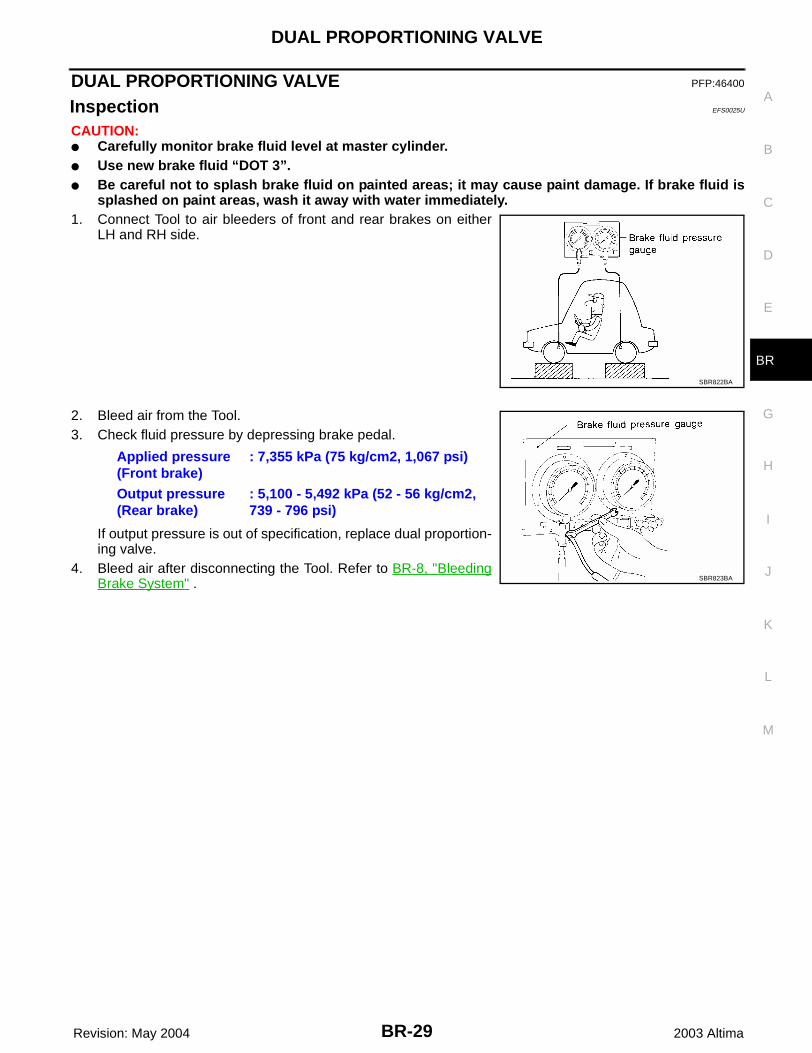
CAUTION:● Carefully monitor brake fluid level at master cylinder.● Use new brake fluid “DOT 3”.● Be careful not to splash brake fluid on painted areas; it may cause paint damage. If brake fluid is
splashed on paint areas, wash it away with water immediately.1. Connect Tool to air bleeders of front and rear brakes on either
LH and RH side.
2. Bleed air from the Tool.3. Check fluid pressure by depressing brake pedal.
If output pressure is out of specification, replace dual proportion-ing valve.
4. Bleed air after disconnecting the Tool. Refer to BR-8, "BleedingBrake System" .
SBR822BA
Applied pressure (Front brake)
: 7,355 kPa (75 kg/cm2, 1,067 psi)
Output pressure (Rear brake)
: 5,100 - 5,492 kPa (52 - 56 kg/cm2, 739 - 796 psi)
SBR823BA
BR-30
SERVICE DATA AND SPECIFICATIONS (SDS)
Revision: May 2004 2003 Altima
SERVICE DATA AND SPECIFICATIONS (SDS) PFP:00030
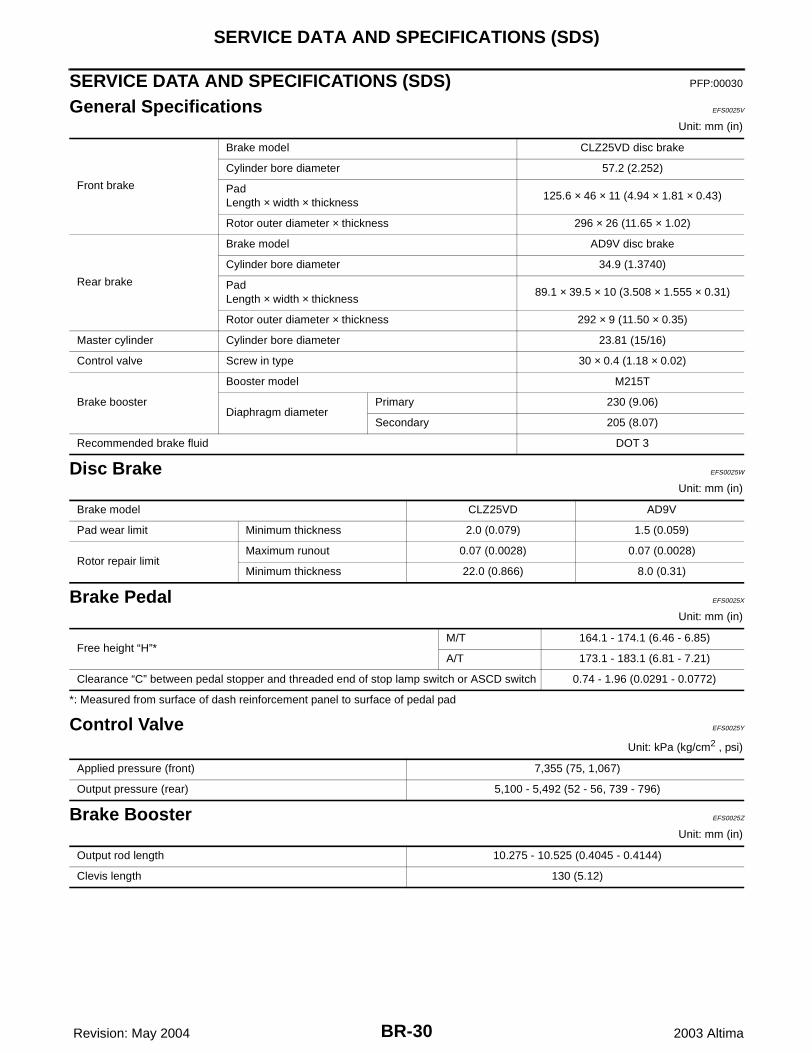
General Specifications EFS0025V
Unit: mm (in)
Disc Brake EFS0025W
Unit: mm (in)
Brake Pedal EFS0025X
Unit: mm (in)
*: Measured from surface of dash reinforcement panel to surface of pedal pad
Control Valve EFS0025Y
Unit: kPa (kg/cm2 , psi)
Brake Booster EFS0025Z
Unit: mm (in)
Front brake
Brake model CLZ25VD disc brake
Cylinder bore diameter 57.2 (2.252)
PadLength × width × thickness
125.6 × 46 × 11 (4.94 × 1.81 × 0.43)
Rotor outer diameter × thickness 296 × 26 (11.65 × 1.02)
Rear brake
Brake model AD9V disc brake
Cylinder bore diameter 34.9 (1.3740)
PadLength × width × thickness
89.1 × 39.5 × 10 (3.508 × 1.555 × 0.31)
Rotor outer diameter × thickness 292 × 9 (11.50 × 0.35)
Master cylinder Cylinder bore diameter 23.81 (15/16)
Control valve Screw in type 30 × 0.4 (1.18 × 0.02)
Brake booster
Booster model M215T
Diaphragm diameterPrimary 230 (9.06)
Secondary 205 (8.07)
Recommended brake fluid DOT 3
Brake model CLZ25VD AD9V
Pad wear limit Minimum thickness 2.0 (0.079) 1.5 (0.059)
Rotor repair limitMaximum runout 0.07 (0.0028) 0.07 (0.0028)
Minimum thickness 22.0 (0.866) 8.0 (0.31)
Free height “H”*M/T 164.1 - 174.1 (6.46 - 6.85)
A/T 173.1 - 183.1 (6.81 - 7.21)
Clearance “C” between pedal stopper and threaded end of stop lamp switch or ASCD switch 0.74 - 1.96 (0.0291 - 0.0772)
Applied pressure (front) 7,355 (75, 1,067)
Output pressure (rear) 5,100 - 5,492 (52 - 56, 739 - 796)
Output rod length 10.275 - 10.525 (0.4045 - 0.4144)
Clevis length 130 (5.12)