Embed Size (px)
DESCRIPTION
2003 Nissan Altima 2.5 Serivce Manual
Citation preview
GW-1
GLASSES, WINDOW SYSTEM & MIRRORS
I BODY
CONTENTS
C
D
E
F
G
H
J
K
L
M
SECTION
A
B
GW
Revision: May 2004 2003 Altima
PRECAUTIONS .......................................................... 3Precautions for Supplemental Restraint System (SRS) “AIR BAG” and “SEAT BELT PRE-TEN-SIONER” .................................................................. 3Handling for Adhesive and Primer ........................... 3Trouble Diagnosis Precaution .................................. 3
PREPARATION ........................................................... 4Special Service Tool ................................................. 4Commercial Service Tool ......................................... 4
SQUEAK AND RATTLE TROUBLE DIAGNOSES ..... 5Work Flow ................................................................ 5
CUSTOMER INTERVIEW ..................................... 5DUPLICATE THE NOISE AND TEST DRIVE ....... 6CHECK RELATED SERVICE BULLETINS ........... 6LOCATE THE NOISE AND IDENTIFY THE ROOT CAUSE ...................................................... 6REPAIR THE CAUSE ........................................... 6CONFIRM THE REPAIR ....................................... 7
Generic Squeak and Rattle Troubleshooting ........... 7INSTRUMENT PANEL .......................................... 7CENTER CONSOLE ............................................. 7DOORS ................................................................. 7TRUNK .................................................................. 8SUNROOF/HEADLINING ..................................... 8SEATS ................................................................... 8UNDERHOOD ....................................................... 8
Diagnostic Worksheet .............................................. 9WINDSHIELD GLASS ...............................................11
Removal and Installation .........................................11REMOVAL ............................................................11INSTALLATION ....................................................11
REAR WINDOW GLASS AND MOLDING ............... 13Removal and Installation ........................................ 13
REMOVAL ........................................................... 13INSTALLATION ................................................... 13
POWER WINDOW SYSTEM .................................... 15Component Parts and Harness Connector Location ... 15System Description ................................................ 15
AUTO OPERATION ............................................ 15POWER WINDOW LOCK ................................... 15
DELAYED POWER OPERATION ....................... 15ANTI-PINCH DETECTION FUNCTION ............... 16
Schematic (With Left Front Only Power Window Anti-pinch System) ................................................. 17Wiring Diagram – WINDOW – (With Left Front Only Power Window Anti-pinch System) ........................ 18Terminal and Reference Value for Power Window Main Switch ............................................................ 22Schematic (With Left and Right Front Power Win-dow Anti-pinch System) .......................................... 23Wiring Diagram – WINDOW – (With Left and Right Front Power Window Anti-pinch System) ............... 24Terminal and Reference Value for Power Window Main Switch ............................................................ 28CONSULT-II Inspection Procedure ......................... 28
ACTIVE TEST ..................................................... 30Trouble Diagnoses ................................................. 30Encoder and Limit Switch Check (Driver side) ....... 31Encoder and Limit Switch Check (Passenger side with left and right front power window anti-pinch sys-tem) ........................................................................ 32
FRONT DOOR GLASS AND REGULATOR ............. 34Removal and Installation ........................................ 34
REMOVAL ........................................................... 34INSPECTION AFTER REMOVAL ....................... 35DISASSEMBLY AND ASSEMBLY ....................... 35FITTING INSPECTION ....................................... 35INSTALLATION ................................................... 35SETTING AFTER INSTALLATION ...................... 35
REAR DOOR GLASS AND REGULATOR ............... 37Removal and Installation ........................................ 37
REMOVAL ........................................................... 37INSTALLATION ................................................... 38INSPECTION AFTER REMOVAL ....................... 38FITTING INSPECTION ....................................... 38
INSIDE MIRROR ....................................................... 39Wiring Diagram –I/MIRR– ...................................... 39Removal and Installation ........................................ 40
INSIDE MIRROR ................................................. 40REAR WINDOW DEFOGGER .................................. 41
GW-2 Revision: May 2004 2003 Altima
Component Parts and Harness Connector Location ... 41System Description ................................................. 41
SYSTEM DIAGRAM ............................................ 42CAN Communication System Description .............. 42
FOR TCS MODELS ............................................. 43FOR A/T MODELS .............................................. 44FOR M/T MODELS .............................................. 45
Wiring Diagram –DEF– WITH MANUAL A/C .......... 47Wiring Diagram – DEF – WITH AUTO A/C ............. 48Wiring Diagram –H/MIRR– ..................................... 49Terminal and Reference Value for BCM ................. 51Terminal and Reference Value for IPDM E/R ......... 51Work Flow ............................................................... 51Preliminary Check .................................................. 52
FUSE CHECK ..................................................... 52CONSULT–II Function ............................................ 52
CONSULT–II BASIC OPERATION PROCE-DURE ...................................................................52DATA MONITOR ..................................................53ACTIVE TEST ......................................................53
Trouble Diagnosis ...................................................54Filament Check .......................................................57Filament Repair .......................................................58
REPAIR EQUIPMENT .........................................58REPAIRING PROCEDURE .................................58
DOOR MIRROR .........................................................60Wiring Diagram –MIRROR– ...................................60Removal and Installation .........................................61Door Mirror Glass ....................................................61
REMOVAL ............................................................61INSTALLATION ....................................................61
PRECAUTIONS
GW-3
C
D
E
F
G
H
J
K
L
M
A
B
GW
Revision: May 2004 2003 Altima
PRECAUTIONS PFP:00001
Precautions for Supplemental Restraint System (SRS) “AIR BAG” and “SEAT BELT PRE-TENSIONER” EIS001AD
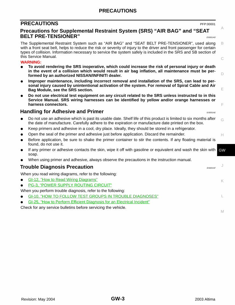
The Supplemental Restraint System such as “AIR BAG” and “SEAT BELT PRE-TENSIONER”, used alongwith a front seat belt, helps to reduce the risk or severity of injury to the driver and front passenger for certaintypes of collision. Information necessary to service the system safely is included in the SRS and SB section ofthis Service Manual.WARNING:● To avoid rendering the SRS inoperative, which could increase the risk of personal injury or death
in the event of a collision which would result in air bag inflation, all maintenance must be per-formed by an authorized NISSAN/INFINITI dealer.
● Improper maintenance, including incorrect removal and installation of the SRS, can lead to per-sonal injury caused by unintentional activation of the system. For removal of Spiral Cable and AirBag Module, see the SRS section.
● Do not use electrical test equipment on any circuit related to the SRS unless instructed to in thisService Manual. SRS wiring harnesses can be identified by yellow and/or orange harnesses orharness connectors.
Handling for Adhesive and Primer EIS001AE
● Do not use an adhesive which is past its usable date. Shelf life of this product is limited to six months afterthe date of manufacture. Carefully adhere to the expiration or manufacture date printed on the box.
● Keep primers and adhesive in a cool, dry place. Ideally, they should be stored in a refrigerator.● Open the seal of the primer and adhesive just before application. Discard the remainder.● Before application, be sure to shake the primer container to stir the contents. If any floating material is
found, do not use it.● If any primer or adhesive contacts the skin, wipe it off with gasoline or equivalent and wash the skin with
soap.● When using primer and adhesive, always observe the precautions in the instruction manual.
Trouble Diagnosis Precaution EIS001AF
When you read wiring diagrams, refer to the following:● GI-12, "How to Read Wiring Diagrams"● PG-3, "POWER SUPPLY ROUTING CIRCUIT"When you perform trouble diagnosis, refer to the following:● GI-10, "HOW TO FOLLOW TEST GROUPS IN TROUBLE DIAGNOSES"● GI-25, "How to Perform Efficient Diagnosis for an Electrical Incident"Check for any service bulletins before servicing the vehicle.
GW-4
PREPARATION
Revision: May 2004 2003 Altima
PREPARATION PFP:00002
Special Service Tool EIS001AG
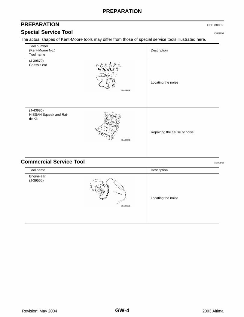
The actual shapes of Kent-Moore tools may differ from those of special service tools illustrated here.
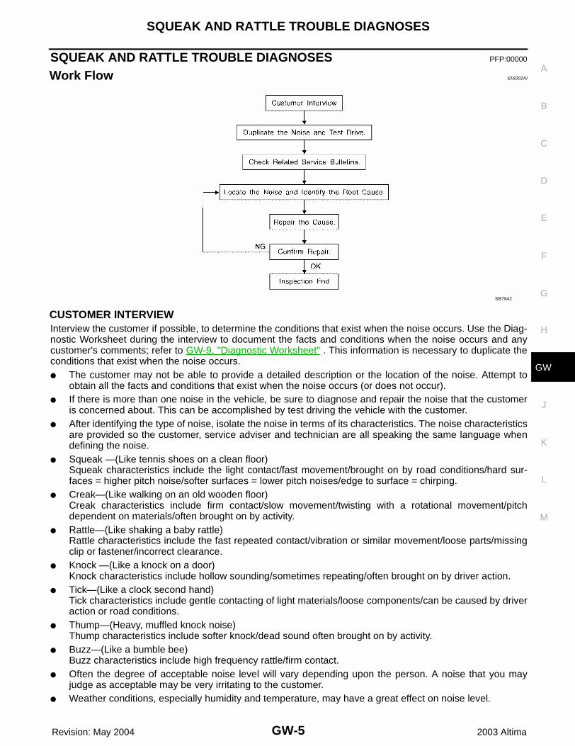
Commercial Service Tool EIS001AH
Tool number(Kent-Moore No.)Tool name
Description
(J-39570)Chassis ear
Locating the noise
(J-43980)NISSAN Squeak and Rat-tle Kit
Repairing the cause of noise
SIIA0993E
SIIA0994E
Tool name Description
Engine ear(J-39565)
Locating the noise
SIIA0995E
SQUEAK AND RATTLE TROUBLE DIAGNOSES
GW-5
C
D
E
F
G
H
J
K
L
M
A
B
GW
Revision: May 2004 2003 Altima
SQUEAK AND RATTLE TROUBLE DIAGNOSES PFP:00000
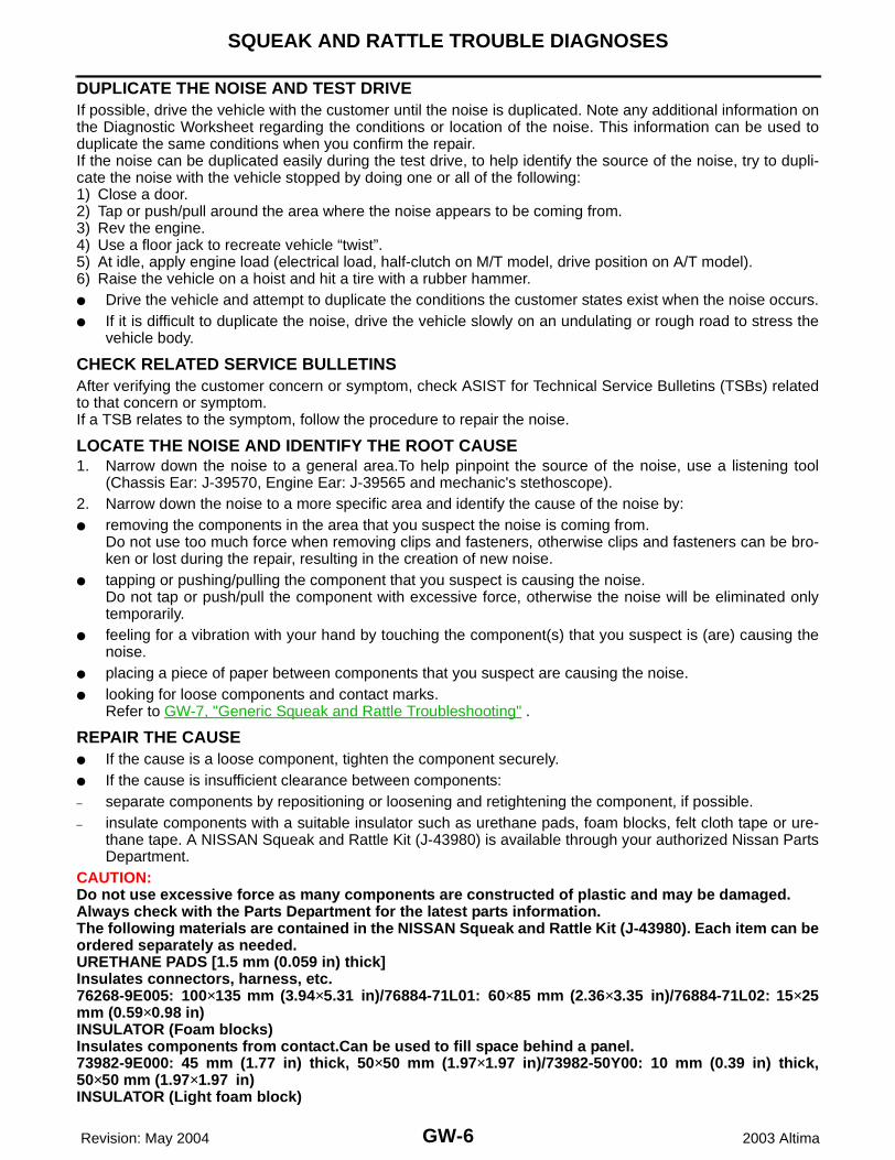
Work Flow EIS001AI
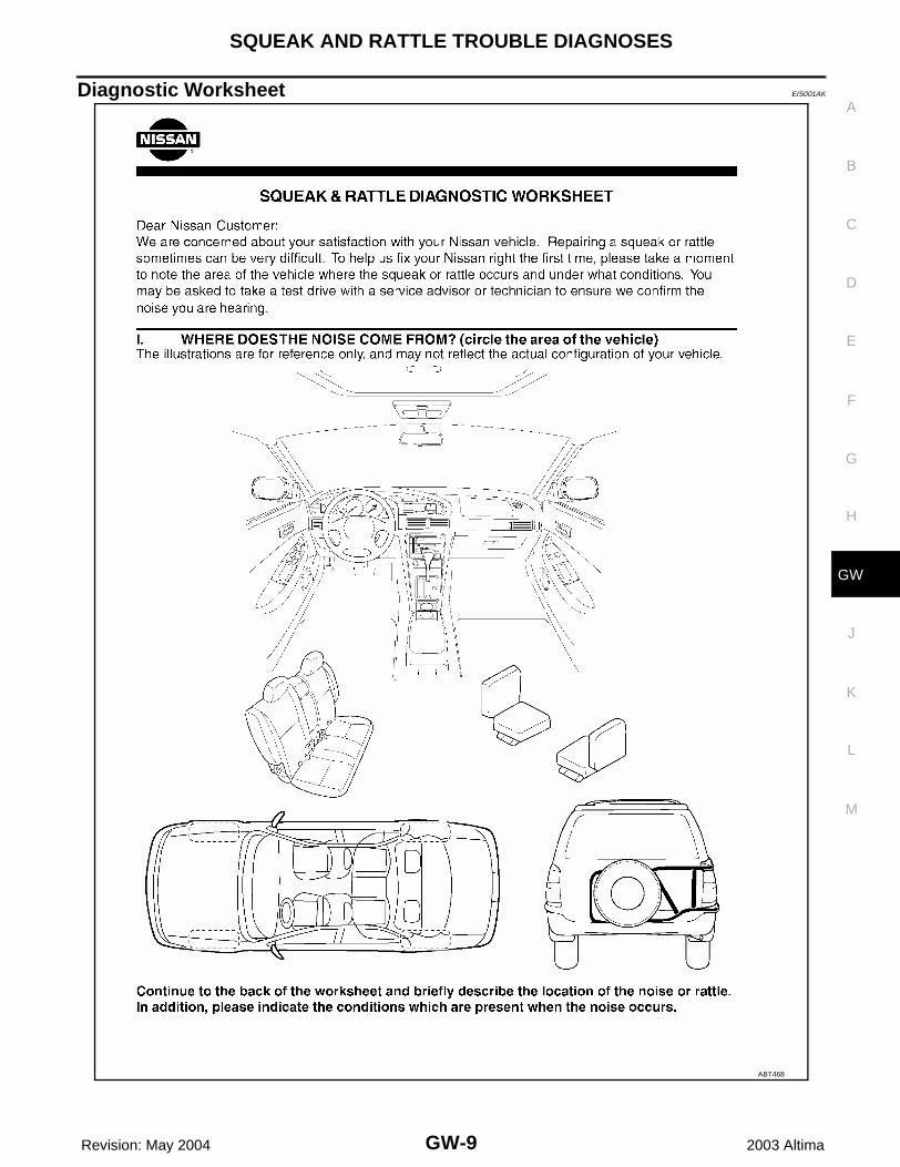
CUSTOMER INTERVIEWInterview the customer if possible, to determine the conditions that exist when the noise occurs. Use the Diag-nostic Worksheet during the interview to document the facts and conditions when the noise occurs and anycustomer's comments; refer to GW-9, "Diagnostic Worksheet" . This information is necessary to duplicate theconditions that exist when the noise occurs.● The customer may not be able to provide a detailed description or the location of the noise. Attempt to
obtain all the facts and conditions that exist when the noise occurs (or does not occur).● If there is more than one noise in the vehicle, be sure to diagnose and repair the noise that the customer
is concerned about. This can be accomplished by test driving the vehicle with the customer. ● After identifying the type of noise, isolate the noise in terms of its characteristics. The noise characteristics
are provided so the customer, service adviser and technician are all speaking the same language whendefining the noise.
● Squeak —(Like tennis shoes on a clean floor)Squeak characteristics include the light contact/fast movement/brought on by road conditions/hard sur-faces = higher pitch noise/softer surfaces = lower pitch noises/edge to surface = chirping.
● Creak—(Like walking on an old wooden floor)Creak characteristics include firm contact/slow movement/twisting with a rotational movement/pitchdependent on materials/often brought on by activity.
● Rattle—(Like shaking a baby rattle)Rattle characteristics include the fast repeated contact/vibration or similar movement/loose parts/missingclip or fastener/incorrect clearance.
● Knock —(Like a knock on a door)Knock characteristics include hollow sounding/sometimes repeating/often brought on by driver action.
● Tick—(Like a clock second hand)Tick characteristics include gentle contacting of light materials/loose components/can be caused by driveraction or road conditions.
● Thump—(Heavy, muffled knock noise)Thump characteristics include softer knock/dead sound often brought on by activity.
● Buzz—(Like a bumble bee)Buzz characteristics include high frequency rattle/firm contact.
● Often the degree of acceptable noise level will vary depending upon the person. A noise that you mayjudge as acceptable may be very irritating to the customer.
● Weather conditions, especially humidity and temperature, may have a great effect on noise level.
SBT842
GW-6
SQUEAK AND RATTLE TROUBLE DIAGNOSES
Revision: May 2004 2003 Altima
DUPLICATE THE NOISE AND TEST DRIVEIf possible, drive the vehicle with the customer until the noise is duplicated. Note any additional information onthe Diagnostic Worksheet regarding the conditions or location of the noise. This information can be used toduplicate the same conditions when you confirm the repair.If the noise can be duplicated easily during the test drive, to help identify the source of the noise, try to dupli-cate the noise with the vehicle stopped by doing one or all of the following:1) Close a door.2) Tap or push/pull around the area where the noise appears to be coming from.3) Rev the engine.4) Use a floor jack to recreate vehicle “twist”.5) At idle, apply engine load (electrical load, half-clutch on M/T model, drive position on A/T model).6) Raise the vehicle on a hoist and hit a tire with a rubber hammer.● Drive the vehicle and attempt to duplicate the conditions the customer states exist when the noise occurs.● If it is difficult to duplicate the noise, drive the vehicle slowly on an undulating or rough road to stress the
vehicle body.
CHECK RELATED SERVICE BULLETINSAfter verifying the customer concern or symptom, check ASIST for Technical Service Bulletins (TSBs) relatedto that concern or symptom.If a TSB relates to the symptom, follow the procedure to repair the noise.
LOCATE THE NOISE AND IDENTIFY THE ROOT CAUSE1. Narrow down the noise to a general area.To help pinpoint the source of the noise, use a listening tool
(Chassis Ear: J-39570, Engine Ear: J-39565 and mechanic's stethoscope).2. Narrow down the noise to a more specific area and identify the cause of the noise by:● removing the components in the area that you suspect the noise is coming from.
Do not use too much force when removing clips and fasteners, otherwise clips and fasteners can be bro-ken or lost during the repair, resulting in the creation of new noise.
● tapping or pushing/pulling the component that you suspect is causing the noise.Do not tap or push/pull the component with excessive force, otherwise the noise will be eliminated onlytemporarily.
● feeling for a vibration with your hand by touching the component(s) that you suspect is (are) causing thenoise.
● placing a piece of paper between components that you suspect are causing the noise.● looking for loose components and contact marks.
Refer to GW-7, "Generic Squeak and Rattle Troubleshooting" .
REPAIR THE CAUSE ● If the cause is a loose component, tighten the component securely.● If the cause is insufficient clearance between components:– separate components by repositioning or loosening and retightening the component, if possible.– insulate components with a suitable insulator such as urethane pads, foam blocks, felt cloth tape or ure-
thane tape. A NISSAN Squeak and Rattle Kit (J-43980) is available through your authorized Nissan PartsDepartment.
CAUTION:Do not use excessive force as many components are constructed of plastic and may be damaged.Always check with the Parts Department for the latest parts information.The following materials are contained in the NISSAN Squeak and Rattle Kit (J-43980). Each item can beordered separately as needed.URETHANE PADS [1.5 mm (0.059 in) thick]Insulates connectors, harness, etc.76268-9E005: 100×135 mm (3.94×5.31 in)/76884-71L01: 60×85 mm (2.36×3.35 in)/76884-71L02: 15×25mm (0.59×0.98 in)INSULATOR (Foam blocks)Insulates components from contact.Can be used to fill space behind a panel.73982-9E000: 45 mm (1.77 in) thick, 50×50 mm (1.97×1.97 in)/73982-50Y00: 10 mm (0.39 in) thick,50×50 mm (1.97×1.97 in)INSULATOR (Light foam block)
SQUEAK AND RATTLE TROUBLE DIAGNOSES
GW-7
C
D
E
F
G
H
J
K
L
M
A
B
GW
Revision: May 2004 2003 Altima
80845-71L00: 30 mm (1.18 in) thick, 30×50 mm (1.18×1.97 in)FELT CLOTH TAPEUsed to insulate where movement does not occur. Ideal for instrument panel applications.68370-4B000: 15×25 mm (0.59×0.98 in) pad/68239-13E00: 5 mm (0.20 in) wide tape roll. The followingmaterials not found in the kit can also be used to repair squeaks and rattles.UHMW(TEFLON) TAPE Insulates where slight movement is present. Ideal for instrument panel applications.SILICONE GREASEUsed instead of UHMW tape that will be visible or not fit.Note: Will only last a few months.SILICONE SPRAYUse when grease cannot be applied.DUCT TAPEUse to eliminate movement.
CONFIRM THE REPAIRConfirm that the cause of a noise is repaired by test driving the vehicle. Operate the vehicle under the sameconditions as when the noise originally occurred. Refer to the notes on the Diagnostic Worksheet.
Generic Squeak and Rattle Troubleshooting EIS001AJ
Refer to Table of Contents for specific component removal and installation information.
INSTRUMENT PANELMost incidents are caused by contact and movement between:1. The cluster lid A and instrument panel2. Acrylic lens and combination meter housing3. Instrument panel to front pillar garnish4. Instrument panel to windshield5. Instrument panel mounting pins6. Wiring harnesses behind the combination meter 7. A/C defroster duct and duct jointThese incidents can usually be located by tapping or moving the components to duplicate the noise or bypressing on the components while driving to stop the noise. Most of these incidents can be repaired by apply-ing felt cloth tape or silicone spray (in hard to reach areas). Urethane pads can be used to insulate wiring har-ness.CAUTION:Do not use silicone spray to isolate a squeak or rattle. If you saturate the area with silicone, you willnot be able to recheck the repair.
CENTER CONSOLEComponents to pay attention to include:1. Shifter assembly cover to finisher2. A/C control unit and cluster lid C3. Wiring harnesses behind audio and A/C control unitThe instrument panel repair and isolation procedures also apply to the center console.
DOORSPay attention to the:1. Finisher and inner panel making a slapping noise2. Inside handle escutcheon to door finisher3. Wiring harnesses tapping 4. Door striker out of alignment causing a popping noise on starts and stopsTapping or moving the components or pressing on them while driving to duplicate the conditions can isolatemany of these incidents. You can usually insulate the areas with felt cloth tape or insulator foam blocks fromthe NISSAN Squeak and Rattle Kit (J-43980) to repair the noise.
GW-8
SQUEAK AND RATTLE TROUBLE DIAGNOSES
Revision: May 2004 2003 Altima
TRUNKTrunk noises are often caused by a loose jack or loose items put into the trunk by the owner.In addition look for:1. Trunk lid bumpers out of adjustment2. Trunk lid striker out of adjustment 3. The trunk lid torsion bars knocking together4. A loose license plate or bracketMost of these incidents can be repaired by adjusting, securing or insulating the item(s) or component(s) caus-ing the noise.
SUNROOF/HEADLININGNoises in the sunroof/headlining area can often be traced to one of the following:1. Sunroof lid, rail, linkage or seals making a rattle or light knocking noise2. Sun visor shaft shaking in the holder3. Front or rear windshield touching headliner and squeaking Again, pressing on the components to stop the noise while duplicating the conditions can isolate most of theseincidents. Repairs usually consist of insulating with felt cloth tape.
SEATSWhen isolating seat noise it's important to note the position the seat is in and the load placed on the seat whenthe noise is present. These conditions should be duplicated when verifying and isolating the cause of thenoise.Cause of seat noise include: 1. Headrest rods and holder 2. A squeak between the seat pad cushion and frame 3. The rear seat back lock and bracket These noises can be isolated by moving or pressing on the suspected components while duplicating the con-ditions under which the noise occurs. Most of these incidents can be repaired by repositioning the componentor applying urethane tape to the contact area.
UNDERHOODSome interior noise may be caused by components under the hood or on the engine wall. The noise is thentransmitted into the passenger compartment.Causes of transmitted underhood noise include:1. Any component mounted to the engine wall2. Components that pass through the engine wall3. Engine wall mounts and connectors4. Loose radiator mounting pins5. Hood bumpers out of adjustment 6. Hood striker out of adjustmentThese noises can be difficult to isolate since they cannot be reached from the interior of the vehicle. The bestmethod is to secure, move or insulate one component at a time and test drive the vehicle. Also, engine RPMor load can be changed to isolate the noise. Repairs can usually be made by moving, adjusting, securing, orinsulating the component causing the noise.
SQUEAK AND RATTLE TROUBLE DIAGNOSES
GW-9
C
D
E
F
G
H
J
K
L
M
A
B
GW
Revision: May 2004 2003 Altima
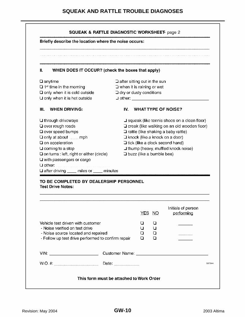
Diagnostic Worksheet EIS001AK
ABT468
GW-10
SQUEAK AND RATTLE TROUBLE DIAGNOSES
Revision: May 2004 2003 Altima
SBT844
WINDSHIELD GLASS
GW-11
C
D
E
F
G
H
J
K
L
M
A
B
GW
Revision: May 2004 2003 Altima
WINDSHIELD GLASS PFP:72712
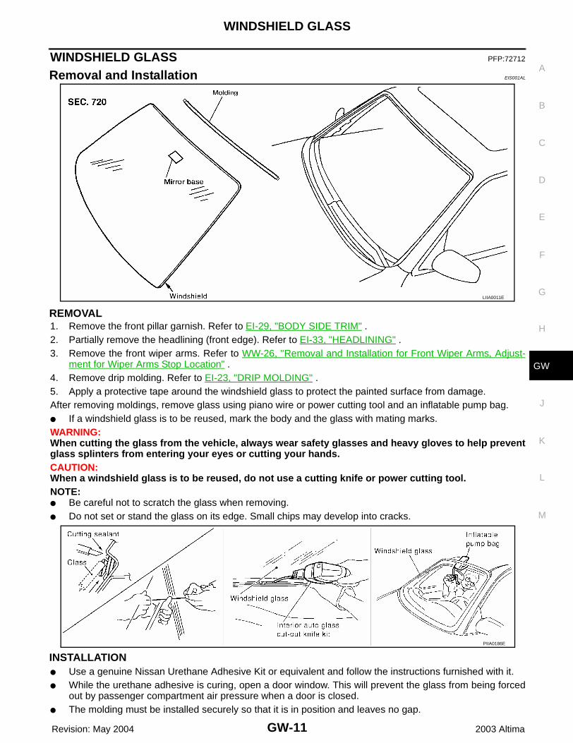
Removal and Installation EIS001AL
REMOVAL1. Remove the front pillar garnish. Refer to EI-29, "BODY SIDE TRIM" .2. Partially remove the headlining (front edge). Refer to EI-33, "HEADLINING" .3. Remove the front wiper arms. Refer to WW-26, "Removal and Installation for Front Wiper Arms, Adjust-
ment for Wiper Arms Stop Location" .4. Remove drip molding. Refer to EI-23, "DRIP MOLDING" .5. Apply a protective tape around the windshield glass to protect the painted surface from damage.After removing moldings, remove glass using piano wire or power cutting tool and an inflatable pump bag.● If a windshield glass is to be reused, mark the body and the glass with mating marks.WARNING:When cutting the glass from the vehicle, always wear safety glasses and heavy gloves to help preventglass splinters from entering your eyes or cutting your hands.CAUTION:When a windshield glass is to be reused, do not use a cutting knife or power cutting tool.NOTE:● Be careful not to scratch the glass when removing.● Do not set or stand the glass on its edge. Small chips may develop into cracks.
INSTALLATION● Use a genuine Nissan Urethane Adhesive Kit or equivalent and follow the instructions furnished with it.● While the urethane adhesive is curing, open a door window. This will prevent the glass from being forced
out by passenger compartment air pressure when a door is closed.● The molding must be installed securely so that it is in position and leaves no gap.
LIIA0011E
PIIA0186E
GW-12
WINDSHIELD GLASS
Revision: May 2004 2003 Altima
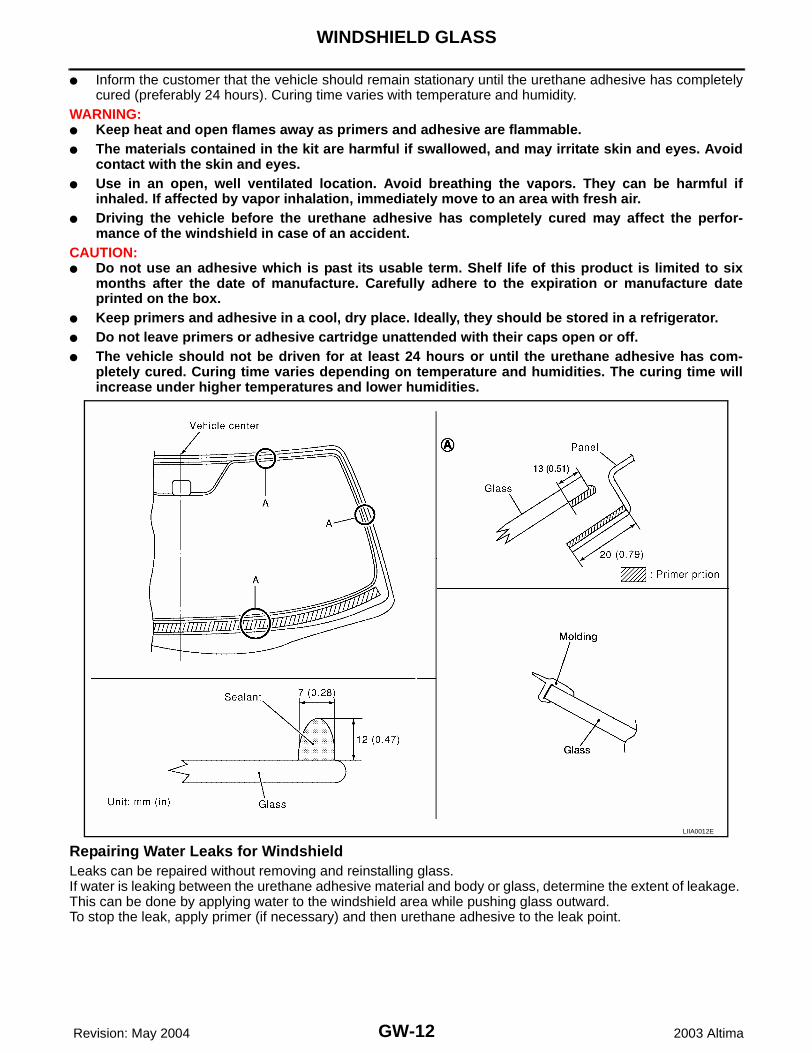
● Inform the customer that the vehicle should remain stationary until the urethane adhesive has completelycured (preferably 24 hours). Curing time varies with temperature and humidity.
WARNING:● Keep heat and open flames away as primers and adhesive are flammable.● The materials contained in the kit are harmful if swallowed, and may irritate skin and eyes. Avoid
contact with the skin and eyes.● Use in an open, well ventilated location. Avoid breathing the vapors. They can be harmful if
inhaled. If affected by vapor inhalation, immediately move to an area with fresh air.● Driving the vehicle before the urethane adhesive has completely cured may affect the perfor-
mance of the windshield in case of an accident.CAUTION:● Do not use an adhesive which is past its usable term. Shelf life of this product is limited to six
months after the date of manufacture. Carefully adhere to the expiration or manufacture dateprinted on the box.
● Keep primers and adhesive in a cool, dry place. Ideally, they should be stored in a refrigerator.● Do not leave primers or adhesive cartridge unattended with their caps open or off.● The vehicle should not be driven for at least 24 hours or until the urethane adhesive has com-
pletely cured. Curing time varies depending on temperature and humidities. The curing time willincrease under higher temperatures and lower humidities.
Repairing Water Leaks for WindshieldLeaks can be repaired without removing and reinstalling glass.If water is leaking between the urethane adhesive material and body or glass, determine the extent of leakage. This can be done by applying water to the windshield area while pushing glass outward.To stop the leak, apply primer (if necessary) and then urethane adhesive to the leak point.
LIIA0012E
REAR WINDOW GLASS AND MOLDING
GW-13
C
D
E
F
G
H
J
K
L
M
A
B
GW
Revision: May 2004 2003 Altima
REAR WINDOW GLASS AND MOLDING PFP:79712
Removal and Installation EIS001AM
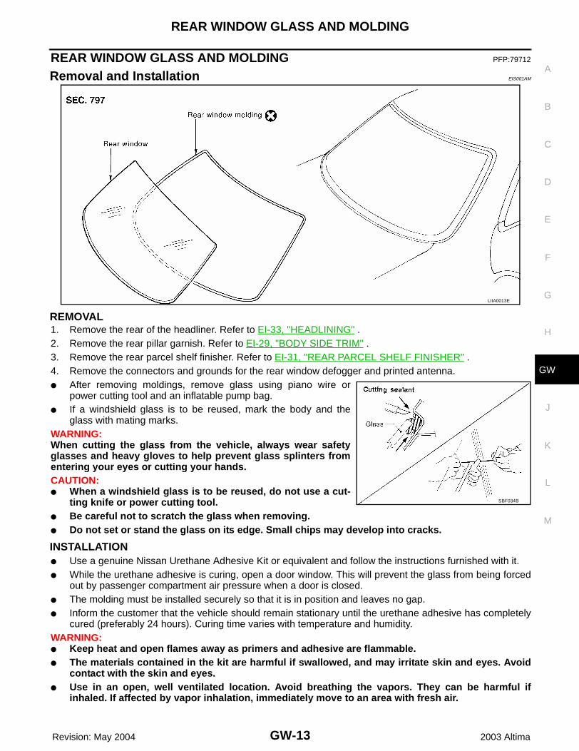
REMOVAL1. Remove the rear of the headliner. Refer to EI-33, "HEADLINING" .2. Remove the rear pillar garnish. Refer to EI-29, "BODY SIDE TRIM" .3. Remove the rear parcel shelf finisher. Refer to EI-31, "REAR PARCEL SHELF FINISHER" .4. Remove the connectors and grounds for the rear window defogger and printed antenna.● After removing moldings, remove glass using piano wire or
power cutting tool and an inflatable pump bag.● If a windshield glass is to be reused, mark the body and the
glass with mating marks.WARNING:When cutting the glass from the vehicle, always wear safetyglasses and heavy gloves to help prevent glass splinters fromentering your eyes or cutting your hands.CAUTION:● When a windshield glass is to be reused, do not use a cut-
ting knife or power cutting tool. ● Be careful not to scratch the glass when removing.● Do not set or stand the glass on its edge. Small chips may develop into cracks.
INSTALLATION● Use a genuine Nissan Urethane Adhesive Kit or equivalent and follow the instructions furnished with it.● While the urethane adhesive is curing, open a door window. This will prevent the glass from being forced
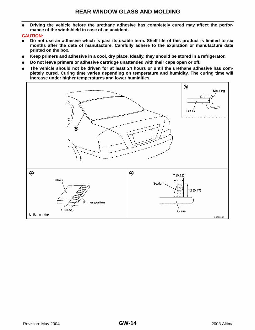
out by passenger compartment air pressure when a door is closed.● The molding must be installed securely so that it is in position and leaves no gap.● Inform the customer that the vehicle should remain stationary until the urethane adhesive has completely
cured (preferably 24 hours). Curing time varies with temperature and humidity.WARNING:● Keep heat and open flames away as primers and adhesive are flammable.● The materials contained in the kit are harmful if swallowed, and may irritate skin and eyes. Avoid
contact with the skin and eyes.● Use in an open, well ventilated location. Avoid breathing the vapors. They can be harmful if
inhaled. If affected by vapor inhalation, immediately move to an area with fresh air.
LIIA0013E
SBF034B
GW-14
REAR WINDOW GLASS AND MOLDING
Revision: May 2004 2003 Altima
● Driving the vehicle before the urethane adhesive has completely cured may affect the perfor-mance of the windshield in case of an accident.
CAUTION:● Do not use an adhesive which is past its usable term. Shelf life of this product is limited to six
months after the date of manufacture. Carefully adhere to the expiration or manufacture dateprinted on the box.
● Keep primers and adhesive in a cool, dry place. Ideally, they should be stored in a refrigerator.● Do not leave primers or adhesive cartridge unattended with their caps open or off.● The vehicle should not be driven for at least 24 hours or until the urethane adhesive has com-
pletely cured. Curing time varies depending on temperature and humidity. The curing time willincrease under higher temperatures and lower humidities.
LIIA0014E
POWER WINDOW SYSTEM
GW-15
C
D
E
F
G
H
J
K
L
M
A
B
GW
Revision: May 2004 2003 Altima
POWER WINDOW SYSTEM PFP:25401
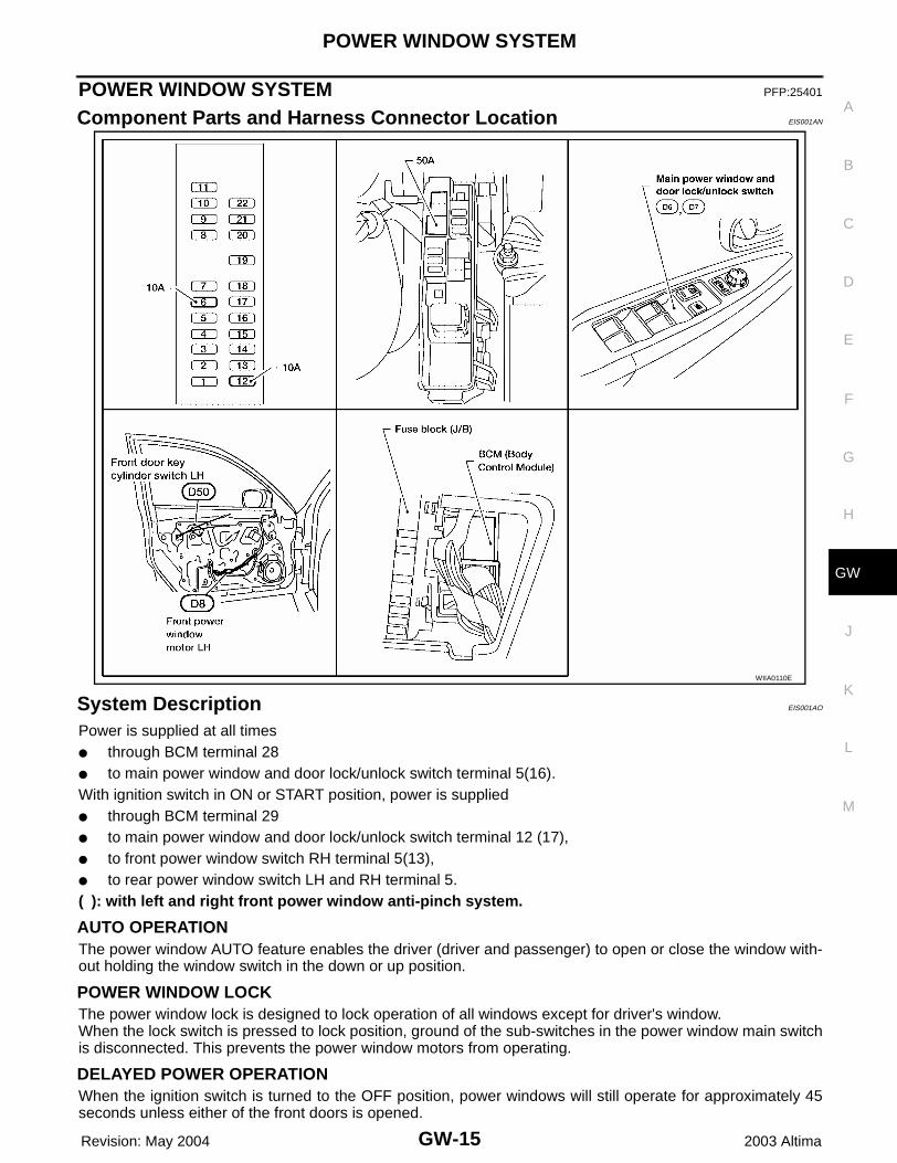
Component Parts and Harness Connector Location EIS001AN
System Description EIS001AO
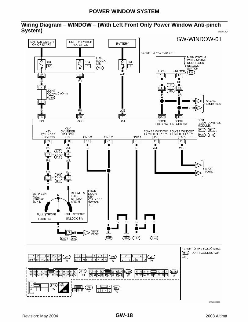
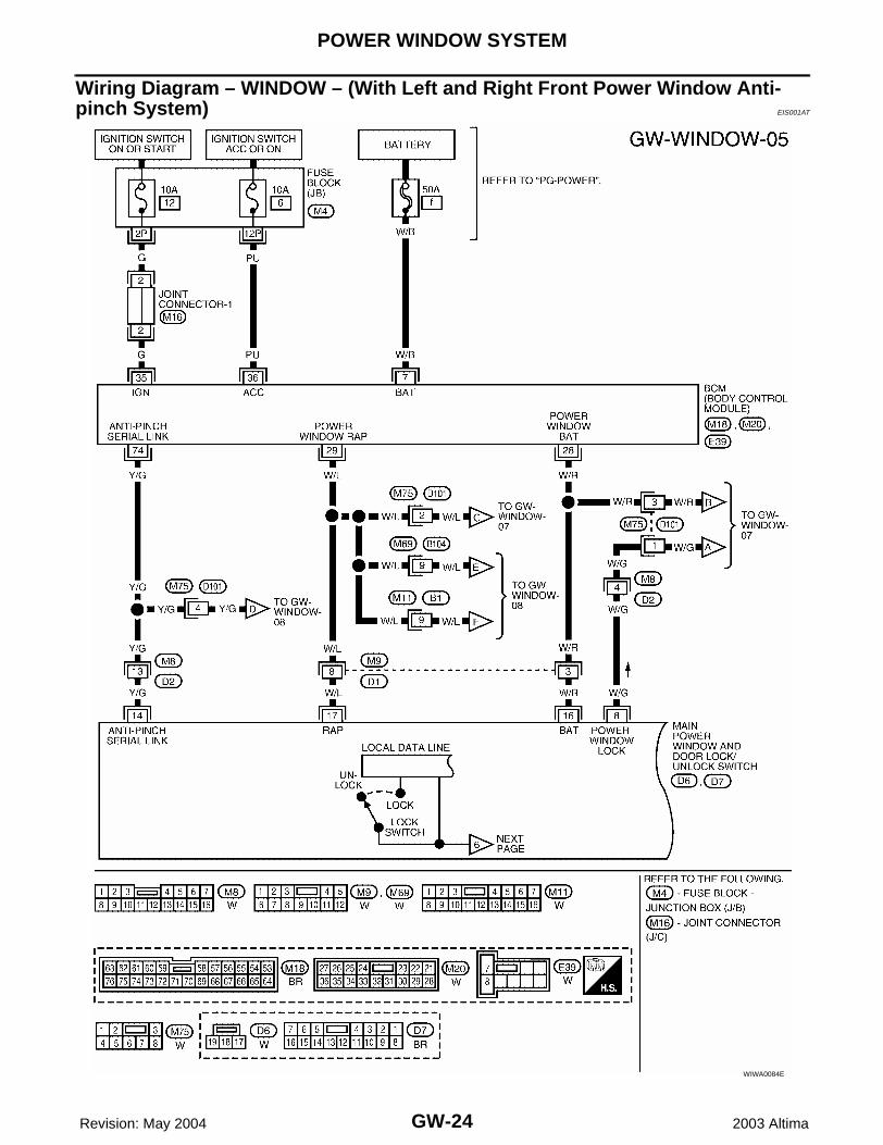
Power is supplied at all times● through BCM terminal 28● to main power window and door lock/unlock switch terminal 5(16).With ignition switch in ON or START position, power is supplied● through BCM terminal 29● to main power window and door lock/unlock switch terminal 12 (17),● to front power window switch RH terminal 5(13),● to rear power window switch LH and RH terminal 5.( ): with left and right front power window anti-pinch system.
AUTO OPERATIONThe power window AUTO feature enables the driver (driver and passenger) to open or close the window with-out holding the window switch in the down or up position.
POWER WINDOW LOCKThe power window lock is designed to lock operation of all windows except for driver's window.When the lock switch is pressed to lock position, ground of the sub-switches in the power window main switchis disconnected. This prevents the power window motors from operating.
DELAYED POWER OPERATIONWhen the ignition switch is turned to the OFF position, power windows will still operate for approximately 45seconds unless either of the front doors is opened.
WIIA0110E
GW-16
POWER WINDOW SYSTEM
Revision: May 2004 2003 Altima
ANTI-PINCH DETECTION FUNCTIONDuring raising operation of driver or passenger power window (if equipped), if door control module detects thatforeign object is pinched, power window lowers approximately 150 mm (5.91 in).NOTE:Depending on environment and driving conditions, if a similar impact or load is applied to power window, itmay lower.
Operation conditions● Driver and passenger door window is between fully-open and just before fully-closed position (when the
limit switch is ON).● During automatic operation when ignition switch is turned ON.● During automatic or manual operation when ignition switch is other than ON position (when the timer
operates).
POWER WINDOW SYSTEM
GW-17
C
D
E
F
G
H
J
K
L
M
A
B
GW
Revision: May 2004 2003 Altima
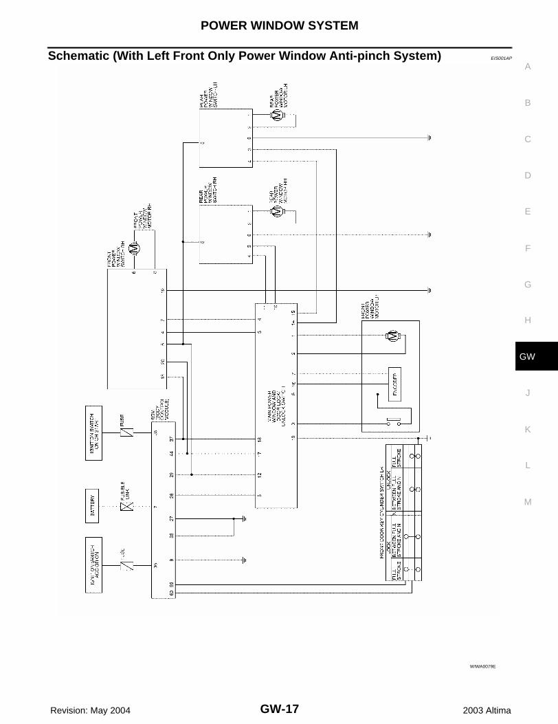
Schematic (With Left Front Only Power Window Anti-pinch System) EIS001AP
WIWA0079E
GW-18
POWER WINDOW SYSTEM
Revision: May 2004 2003 Altima
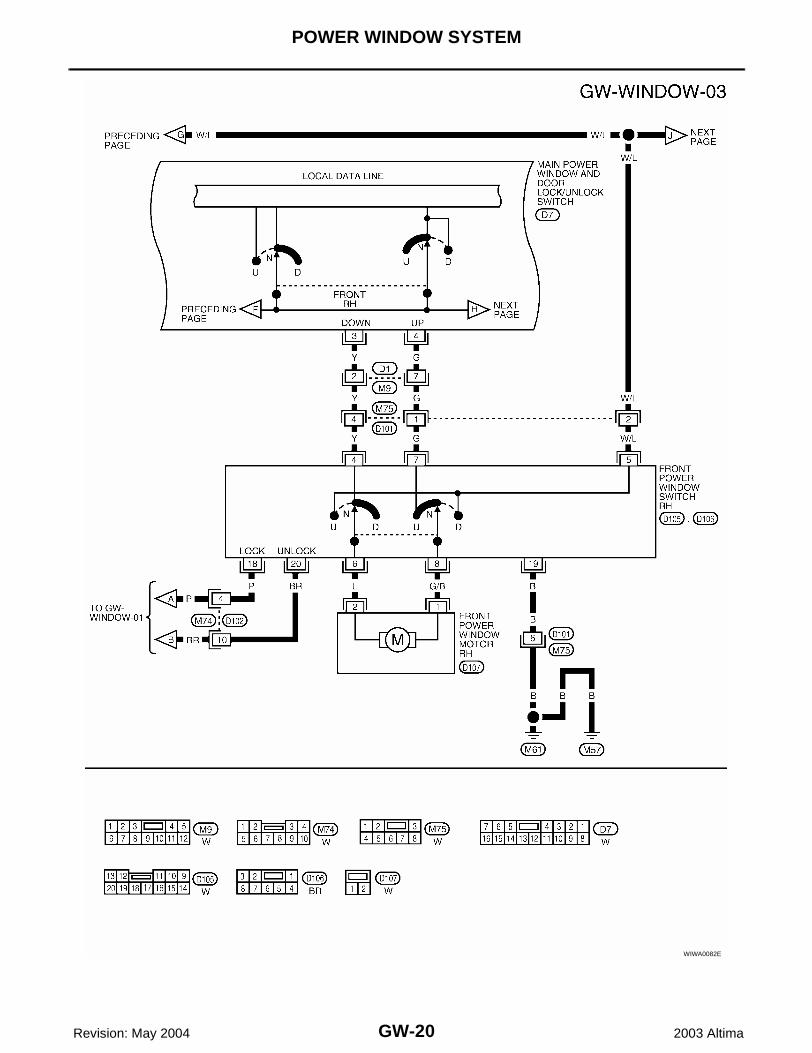
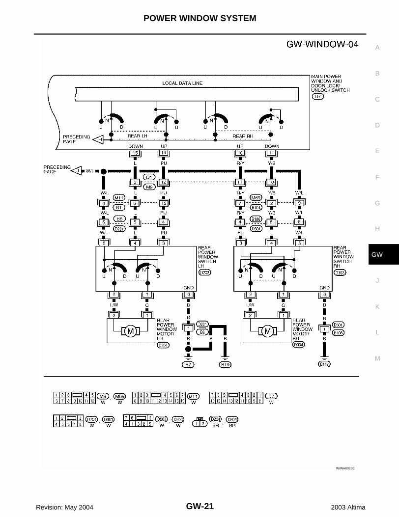
Wiring Diagram – WINDOW – (With Left Front Only Power Window Anti-pinch System) EIS001AQ
WIWA0080E
POWER WINDOW SYSTEM
GW-19
C
D
E
F
G
H
J
K
L
M
A
B
GW
Revision: May 2004 2003 Altima
WIWA0081E
GW-20
POWER WINDOW SYSTEM
Revision: May 2004 2003 Altima
WIWA0082E
POWER WINDOW SYSTEM
GW-21
C
D
E
F
G
H
J
K
L
M
A
B
GW
Revision: May 2004 2003 Altima
WIWA0083E
GW-22
POWER WINDOW SYSTEM
Revision: May 2004 2003 Altima
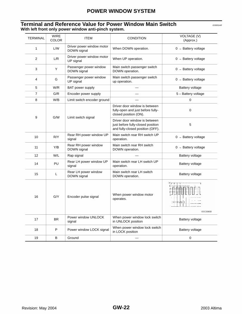
Terminal and Reference Value for Power Window Main Switch EIS001AR
With left front only power window anti-pinch system.
TERMINALWIRE
COLORITEM CONDITION
VOLTAGE (V)(Approx.)
1 L/WDriver power window motor DOWN signal
When DOWN operation. 0 → Battery voltage
2 L/RDriver power window motor UP signal
When UP operation. 0 → Battery voltage
3 YPassenger power window DOWN signal
Main switch passenger switch DOWN operation.
0 → Battery voltage
4 GPassenger power window UP signal
Main switch passenger switch up operation.
0 → Battery voltage
5 W/R BAT power supply — Battery voltage
7 G/R Encoder power supply — 5 – Battery voltage
8 W/B Limit switch encoder ground — 0
9 G/W Limit switch signal
Driver door window is between fully-open and just before fully-closed position (ON).
0
Driver door window is between just before fully-closed position and fully-closed position (OFF).
5
10 R/YRear RH power window UP signal
Main switch rear RH switch UP operation.
0 → Battery voltage
11 Y/BRear RH power window DOWN signal
Main switch rear RH switch DOWN operation.
0 → Battery voltage
12 W/L Rap signal — Battery voltage
14 PURear LH power window UP signal
Main switch rear LH switch UP operation.
Battery voltage
15 LRear LH power window DOWN signal
Main switch rear LH switch DOWN operation.
Battery voltage
16 G/Y Encoder pulse signalWhen power window motor operates.
17 BRPower window UNLOCK signal
When power window lock switchin UNLOCK position
Battery voltage
18 P Power window LOCK signalWhen power window lock switchin LOCK position
Battery voltage
19 B Ground — 0
OCC3383D
POWER WINDOW SYSTEM
GW-23
C
D
E
F
G
H
J
K
L
M
A
B
GW
Revision: May 2004 2003 Altima
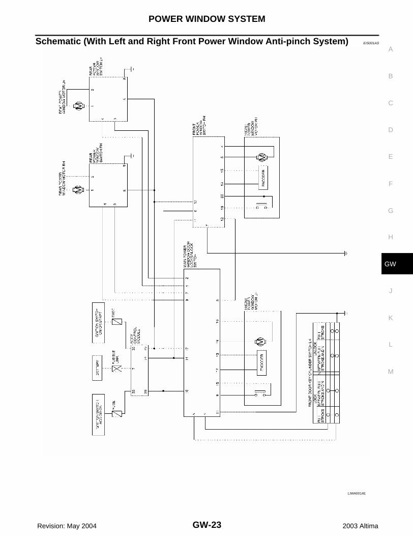
Schematic (With Left and Right Front Power Window Anti-pinch System) EIS001AS
LIWA0014E
GW-24
POWER WINDOW SYSTEM
Revision: May 2004 2003 Altima
Wiring Diagram – WINDOW – (With Left and Right Front Power Window Anti-pinch System) EIS001AT
WIWA0084E
POWER WINDOW SYSTEM
GW-25
C
D
E
F
G
H
J
K
L
M
A
B
GW
Revision: May 2004 2003 Altima
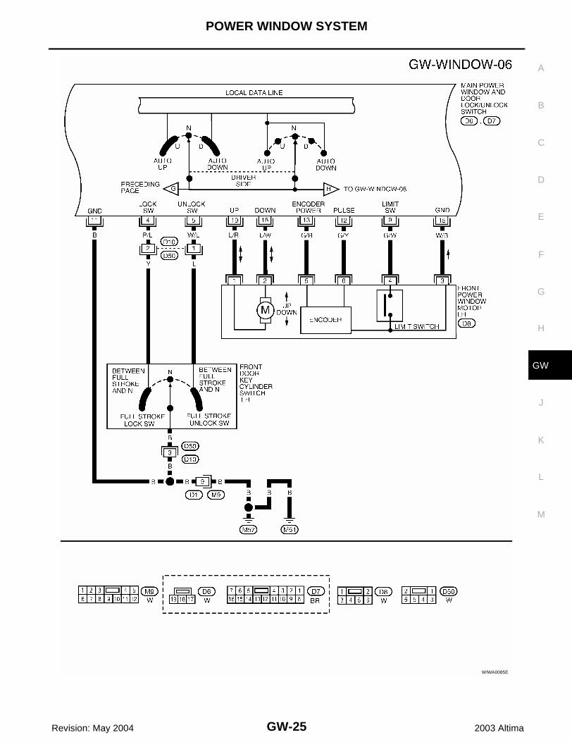
WIWA0085E
GW-26
POWER WINDOW SYSTEM
Revision: May 2004 2003 Altima
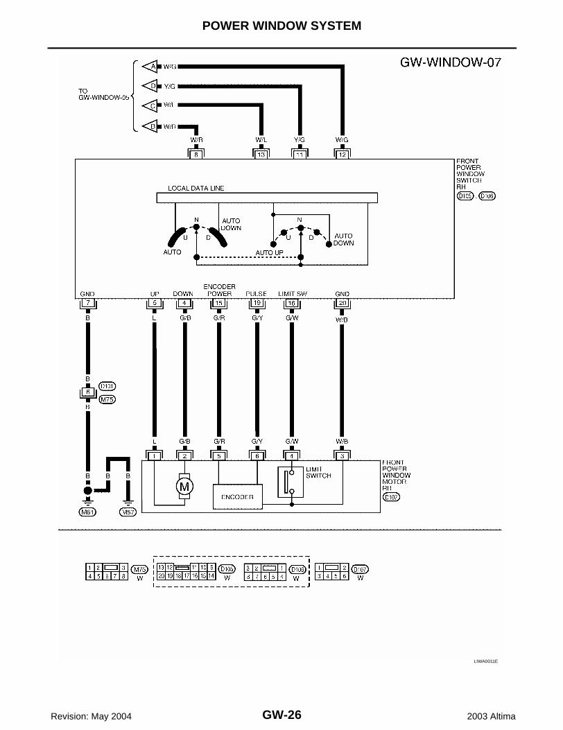
LIWA0011E
POWER WINDOW SYSTEM
GW-27
C
D
E
F
G
H
J
K
L
M
A
B
GW
Revision: May 2004 2003 Altima
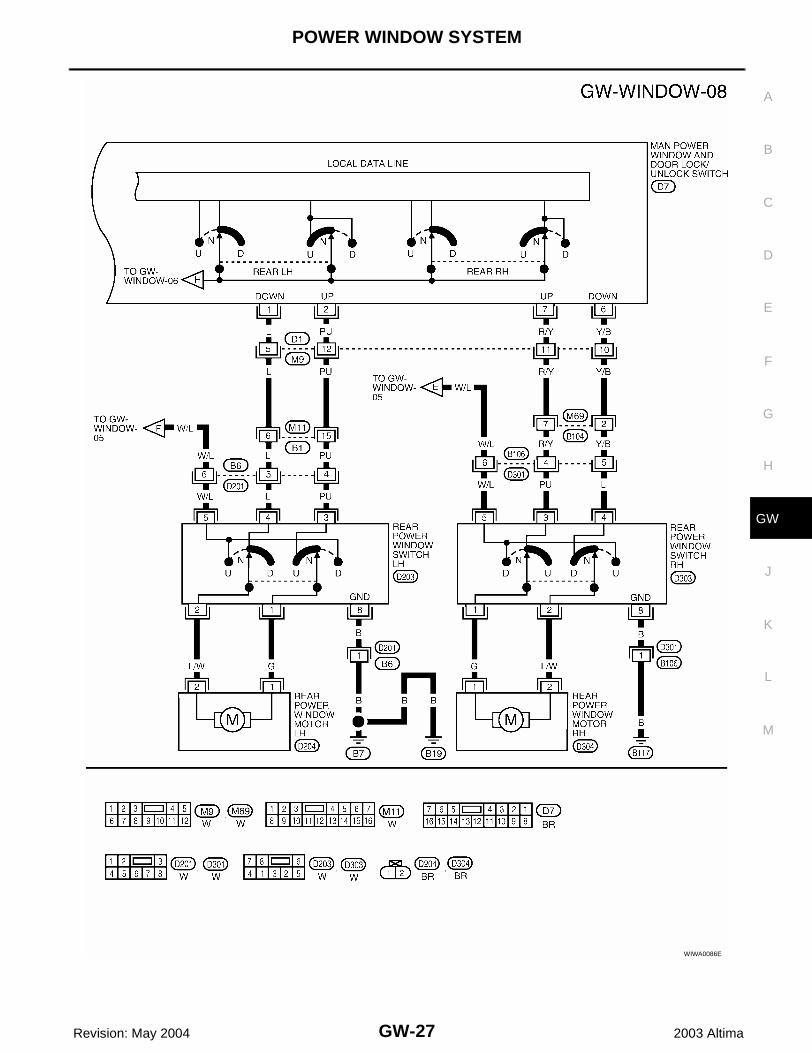
WIWA0086E
GW-28
POWER WINDOW SYSTEM
Revision: May 2004 2003 Altima
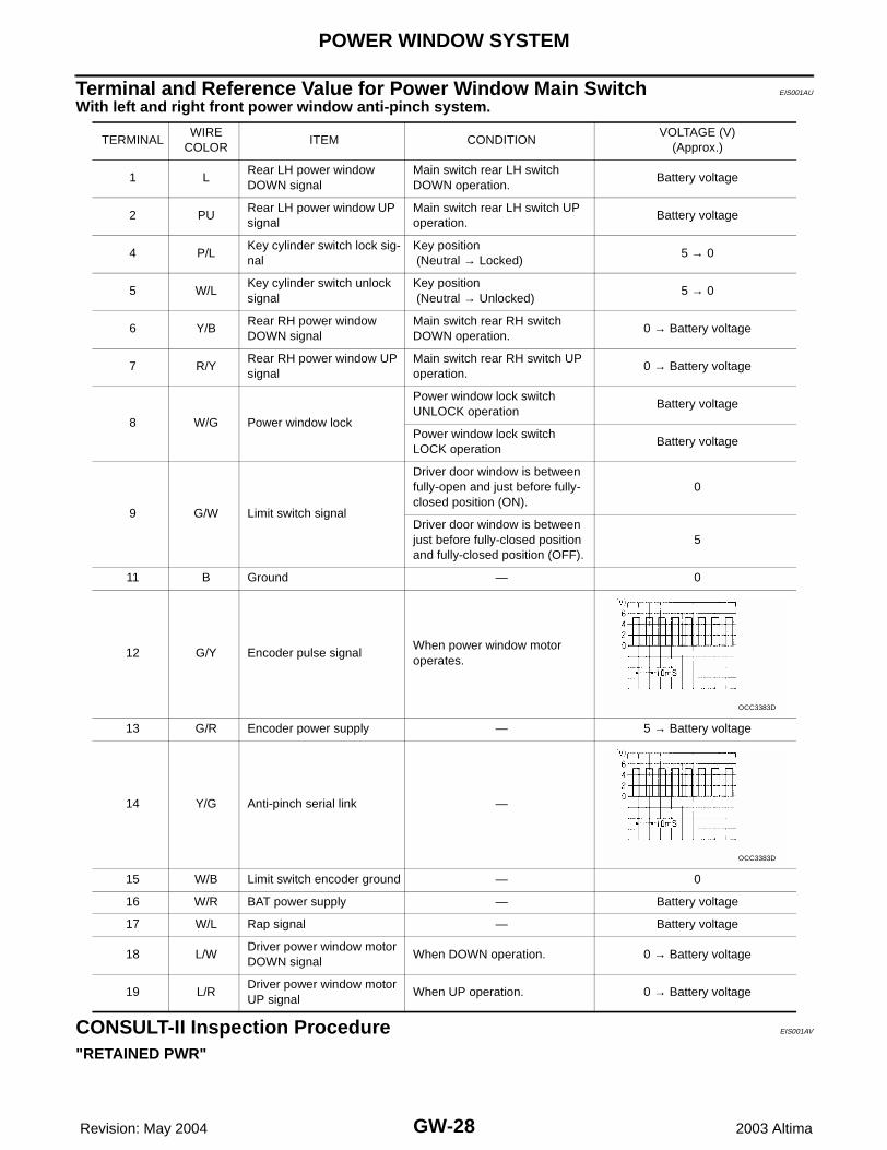
Terminal and Reference Value for Power Window Main Switch EIS001AU
With left and right front power window anti-pinch system.
CONSULT-II Inspection Procedure EIS001AV
"RETAINED PWR"
TERMINALWIRE
COLORITEM CONDITION
VOLTAGE (V)(Approx.)
1 LRear LH power window DOWN signal
Main switch rear LH switch DOWN operation.
Battery voltage
2 PURear LH power window UP signal
Main switch rear LH switch UP operation.
Battery voltage
4 P/LKey cylinder switch lock sig-nal
Key position (Neutral → Locked)
5 → 0
5 W/LKey cylinder switch unlock signal
Key position (Neutral → Unlocked)
5 → 0
6 Y/BRear RH power window DOWN signal
Main switch rear RH switch DOWN operation.
0 → Battery voltage
7 R/YRear RH power window UP signal
Main switch rear RH switch UP operation.
0 → Battery voltage
8 W/G Power window lock
Power window lock switch UNLOCK operation
Battery voltage
Power window lock switch LOCK operation
Battery voltage
9 G/W Limit switch signal
Driver door window is between fully-open and just before fully-closed position (ON).
0
Driver door window is between just before fully-closed position and fully-closed position (OFF).
5
11 B Ground — 0
12 G/Y Encoder pulse signalWhen power window motor operates.
13 G/R Encoder power supply — 5 → Battery voltage
14 Y/G Anti-pinch serial link —
15 W/B Limit switch encoder ground — 0
16 W/R BAT power supply — Battery voltage
17 W/L Rap signal — Battery voltage
18 L/WDriver power window motor DOWN signal
When DOWN operation. 0 → Battery voltage
19 L/RDriver power window motor UP signal
When UP operation. 0 → Battery voltage
OCC3383D
OCC3383D
POWER WINDOW SYSTEM
GW-29
C
D
E
F
G
H
J
K
L
M
A
B
GW
Revision: May 2004 2003 Altima
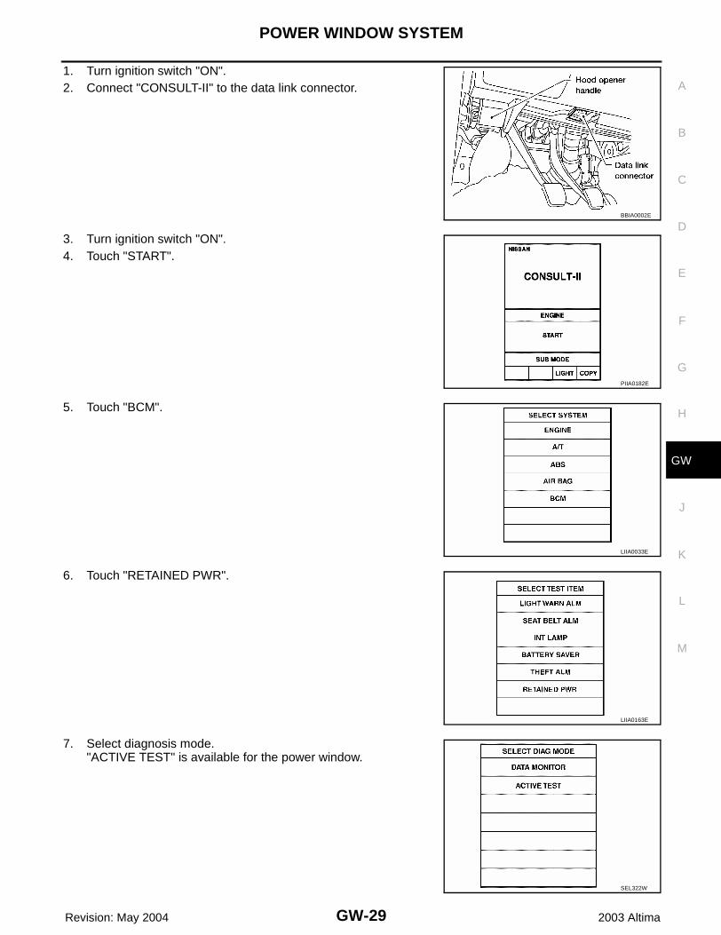
1. Turn ignition switch "ON".2. Connect "CONSULT-II" to the data link connector.
3. Turn ignition switch "ON".4. Touch "START".
5. Touch "BCM".
6. Touch "RETAINED PWR".
7. Select diagnosis mode."ACTIVE TEST" is available for the power window.
BBIA0002E
PIIA0182E
LIIA0033E
LIIA0163E
SEL322W
GW-30
POWER WINDOW SYSTEM
Revision: May 2004 2003 Altima
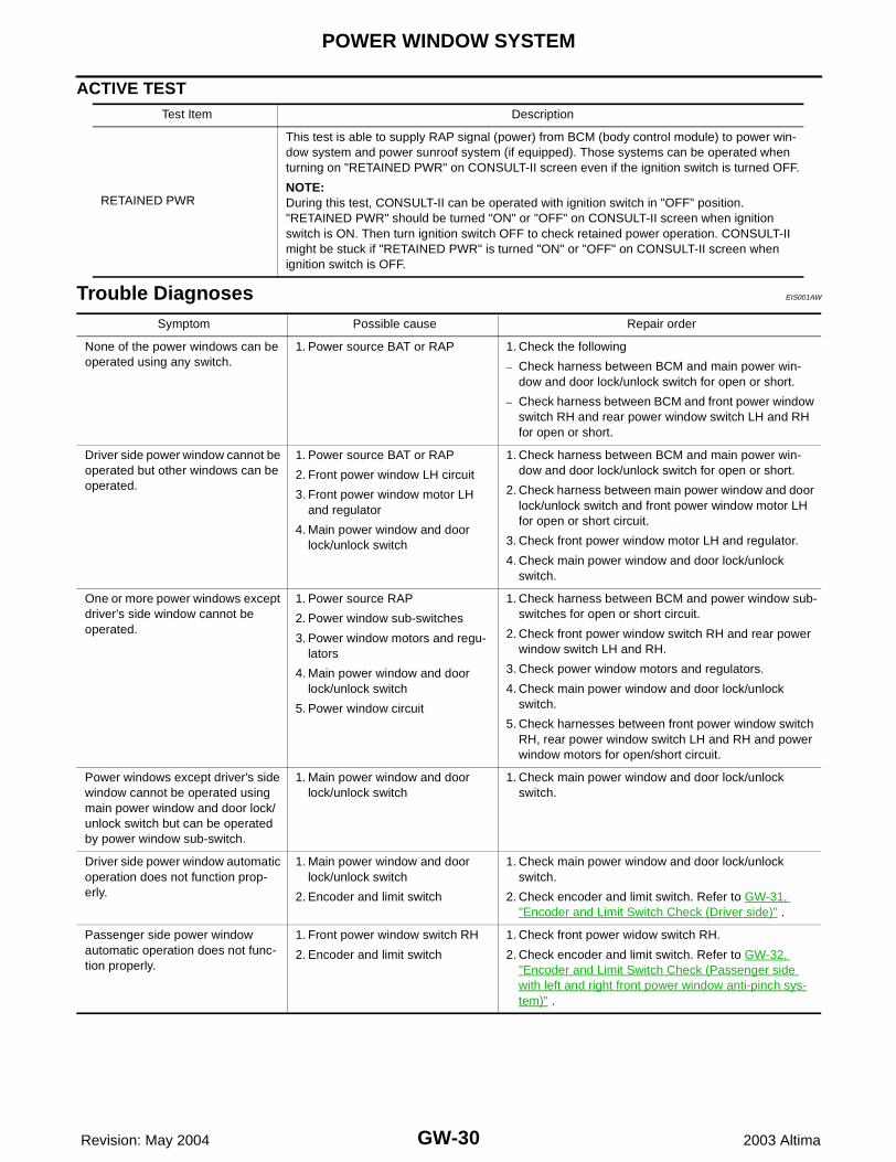
ACTIVE TEST
Trouble Diagnoses EIS001AW
Test Item Description
RETAINED PWR
This test is able to supply RAP signal (power) from BCM (body control module) to power win-dow system and power sunroof system (if equipped). Those systems can be operated when turning on "RETAINED PWR" on CONSULT-II screen even if the ignition switch is turned OFF.
NOTE:During this test, CONSULT-II can be operated with ignition switch in "OFF" position. "RETAINED PWR" should be turned "ON" or "OFF" on CONSULT-II screen when ignition switch is ON. Then turn ignition switch OFF to check retained power operation. CONSULT-II might be stuck if "RETAINED PWR" is turned "ON" or "OFF" on CONSULT-II screen when ignition switch is OFF.
Symptom Possible cause Repair order
None of the power windows can be operated using any switch.
1. Power source BAT or RAP 1. Check the following
– Check harness between BCM and main power win-dow and door lock/unlock switch for open or short.
– Check harness between BCM and front power window switch RH and rear power window switch LH and RH for open or short.
Driver side power window cannot be operated but other windows can be operated.
1. Power source BAT or RAP
2. Front power window LH circuit
3. Front power window motor LH and regulator
4. Main power window and door lock/unlock switch
1. Check harness between BCM and main power win-dow and door lock/unlock switch for open or short.
2. Check harness between main power window and door lock/unlock switch and front power window motor LH for open or short circuit.
3. Check front power window motor LH and regulator.
4. Check main power window and door lock/unlock switch.
One or more power windows except driver's side window cannot be operated.
1. Power source RAP
2. Power window sub-switches
3. Power window motors and regu-lators
4. Main power window and door lock/unlock switch
5. Power window circuit
1. Check harness between BCM and power window sub-switches for open or short circuit.
2. Check front power window switch RH and rear power window switch LH and RH.
3. Check power window motors and regulators.
4. Check main power window and door lock/unlock switch.
5. Check harnesses between front power window switch RH, rear power window switch LH and RH and power window motors for open/short circuit.
Power windows except driver's side window cannot be operated using main power window and door lock/unlock switch but can be operated by power window sub-switch.
1. Main power window and door lock/unlock switch
1. Check main power window and door lock/unlock switch.
Driver side power window automatic operation does not function prop-erly.
1. Main power window and door lock/unlock switch
2. Encoder and limit switch
1. Check main power window and door lock/unlock switch.
2. Check encoder and limit switch. Refer to GW-31, "Encoder and Limit Switch Check (Driver side)" .
Passenger side power window automatic operation does not func-tion properly.
1. Front power window switch RH
2. Encoder and limit switch
1. Check front power widow switch RH.
2. Check encoder and limit switch. Refer to GW-32, "Encoder and Limit Switch Check (Passenger side with left and right front power window anti-pinch sys-tem)" .
POWER WINDOW SYSTEM
GW-31
C
D
E
F
G
H
J
K
L
M
A
B
GW
Revision: May 2004 2003 Altima
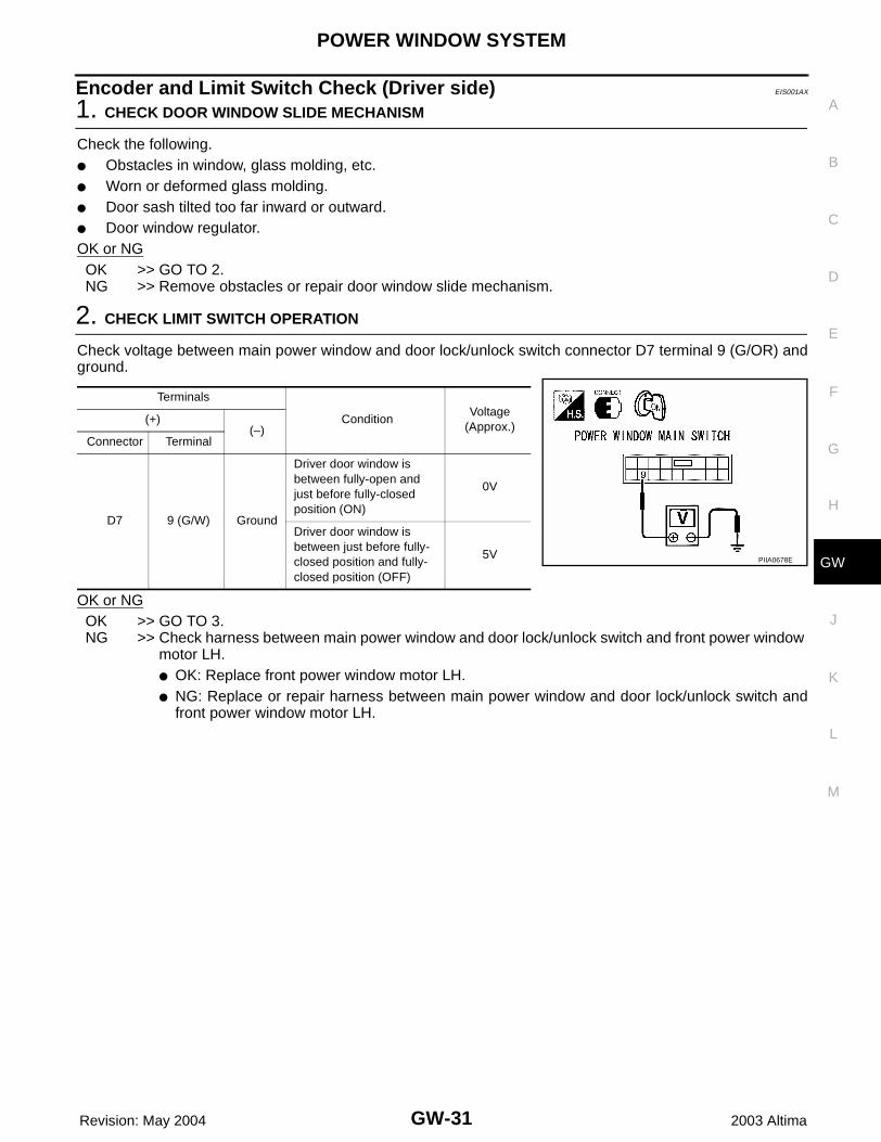
Encoder and Limit Switch Check (Driver side) EIS001AX
1. CHECK DOOR WINDOW SLIDE MECHANISM
Check the following.● Obstacles in window, glass molding, etc.● Worn or deformed glass molding.● Door sash tilted too far inward or outward.● Door window regulator.OK or NGOK >> GO TO 2.NG >> Remove obstacles or repair door window slide mechanism.
2. CHECK LIMIT SWITCH OPERATION
Check voltage between main power window and door lock/unlock switch connector D7 terminal 9 (G/OR) andground.
OK or NGOK >> GO TO 3.NG >> Check harness between main power window and door lock/unlock switch and front power window
motor LH.● OK: Replace front power window motor LH.● NG: Replace or repair harness between main power window and door lock/unlock switch and
front power window motor LH.
Terminals
ConditionVoltage
(Approx.)(+)
(–)Connector Terminal
D7 9 (G/W) Ground
Driver door window is between fully-open and just before fully-closed position (ON)
0V
Driver door window is between just before fully-closed position and fully-closed position (OFF)
5V PIIA0678E
GW-32
POWER WINDOW SYSTEM
Revision: May 2004 2003 Altima
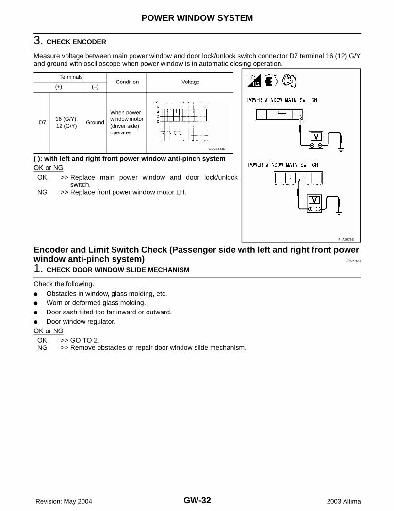
3. CHECK ENCODER
Measure voltage between main power window and door lock/unlock switch connector D7 terminal 16 (12) G/Yand ground with oscilloscope when power window is in automatic closing operation.
( ): with left and right front power window anti-pinch systemOK or NGOK >> Replace main power window and door lock/unlock
switch.NG >> Replace front power window motor LH.
Encoder and Limit Switch Check (Passenger side with left and right front power window anti-pinch system) EIS001AY
1. CHECK DOOR WINDOW SLIDE MECHANISM
Check the following.● Obstacles in window, glass molding, etc.● Worn or deformed glass molding.● Door sash tilted too far inward or outward.● Door window regulator.OK or NGOK >> GO TO 2.NG >> Remove obstacles or repair door window slide mechanism.
TerminalsCondition Voltage
(+) (–)
D716 (G/Y),12 (G/Y)
Ground
When power window motor (driver side) operates.
PIIA0679E
OCC3383D
POWER WINDOW SYSTEM
GW-33
C
D
E
F
G
H
J
K
L
M
A
B
GW
Revision: May 2004 2003 Altima
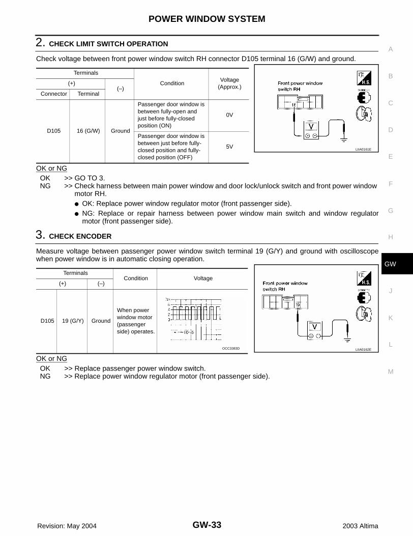
2. CHECK LIMIT SWITCH OPERATION
Check voltage between front power window switch RH connector D105 terminal 16 (G/W) and ground.
OK or NGOK >> GO TO 3.NG >> Check harness between main power window and door lock/unlock switch and front power window
motor RH.● OK: Replace power window regulator motor (front passenger side).● NG: Replace or repair harness between power window main switch and window regulator
motor (front passenger side).
3. CHECK ENCODER
Measure voltage between passenger power window switch terminal 19 (G/Y) and ground with oscilloscopewhen power window is in automatic closing operation.
OK or NGOK >> Replace passenger power window switch.NG >> Replace power window regulator motor (front passenger side).
Terminals
ConditionVoltage
(Approx.)(+)
(–)Connector Terminal
D105 16 (G/W) Ground
Passenger door window is between fully-open and just before fully-closed position (ON)
0V
Passenger door window is between just before fully-closed position and fully-closed position (OFF)
5VLIIA0161E
TerminalsCondition Voltage
(+) (–)
D105 19 (G/Y) Ground
When power window motor (passenger side) operates.
LIIA0162EOCC3383D
GW-34
FRONT DOOR GLASS AND REGULATOR
Revision: May 2004 2003 Altima
FRONT DOOR GLASS AND REGULATOR PFP:80300
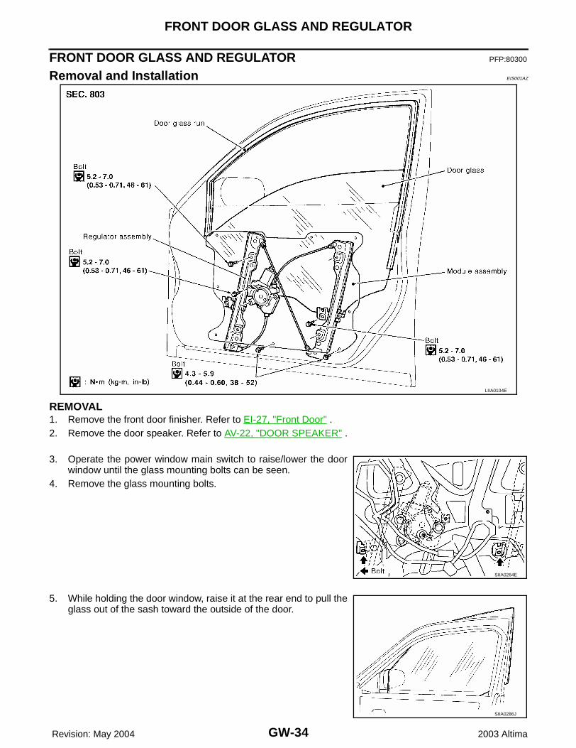
Removal and Installation EIS001AZ
REMOVAL1. Remove the front door finisher. Refer to EI-27, "Front Door" .2. Remove the door speaker. Refer to AV-22, "DOOR SPEAKER" .
3. Operate the power window main switch to raise/lower the doorwindow until the glass mounting bolts can be seen.
4. Remove the glass mounting bolts.
5. While holding the door window, raise it at the rear end to pull theglass out of the sash toward the outside of the door.
LIIA0104E
SIIA0264E
SIIA0286J
FRONT DOOR GLASS AND REGULATOR
GW-35
C
D
E
F
G
H
J
K
L
M
A
B
GW
Revision: May 2004 2003 Altima
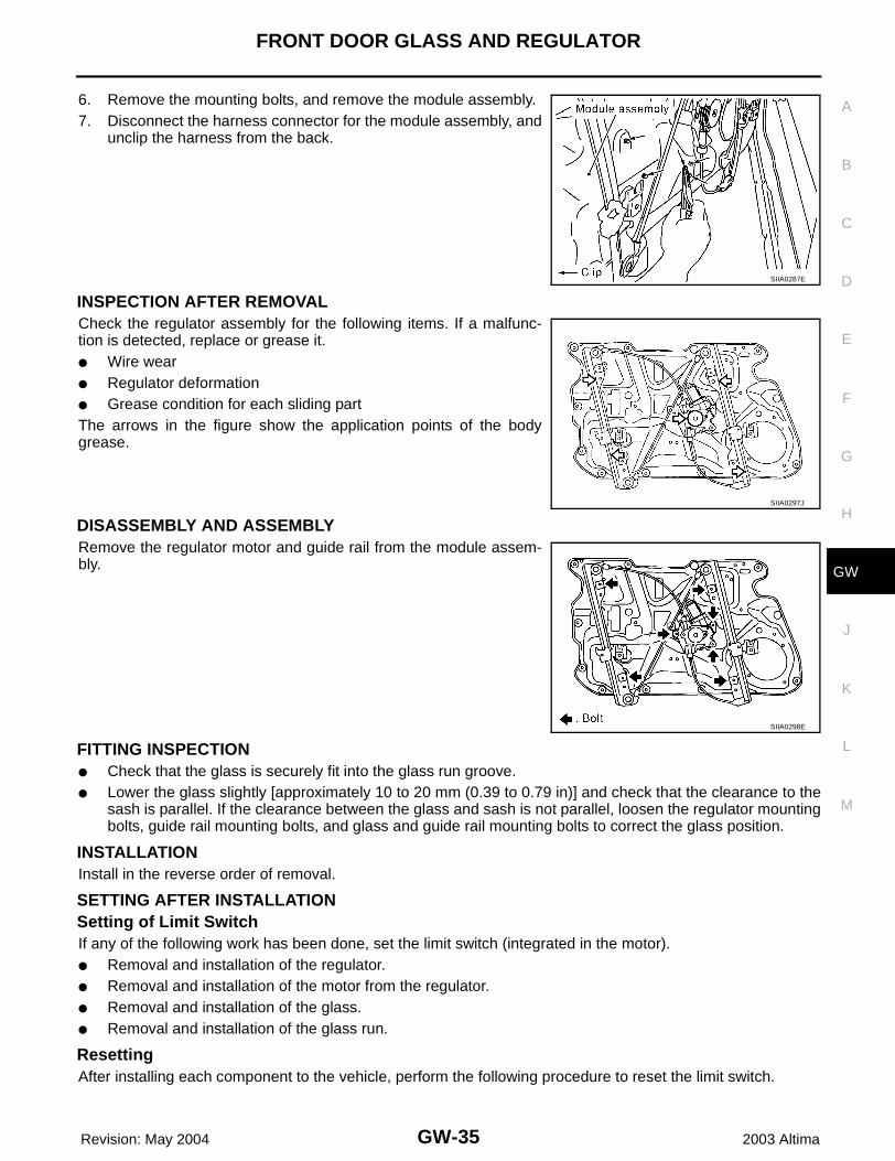
6. Remove the mounting bolts, and remove the module assembly.7. Disconnect the harness connector for the module assembly, and
unclip the harness from the back.
INSPECTION AFTER REMOVALCheck the regulator assembly for the following items. If a malfunc-tion is detected, replace or grease it.● Wire wear● Regulator deformation● Grease condition for each sliding partThe arrows in the figure show the application points of the bodygrease.
DISASSEMBLY AND ASSEMBLYRemove the regulator motor and guide rail from the module assem-bly.
FITTING INSPECTION● Check that the glass is securely fit into the glass run groove.● Lower the glass slightly [approximately 10 to 20 mm (0.39 to 0.79 in)] and check that the clearance to the
sash is parallel. If the clearance between the glass and sash is not parallel, loosen the regulator mountingbolts, guide rail mounting bolts, and glass and guide rail mounting bolts to correct the glass position.
INSTALLATIONInstall in the reverse order of removal.
SETTING AFTER INSTALLATIONSetting of Limit SwitchIf any of the following work has been done, set the limit switch (integrated in the motor).● Removal and installation of the regulator.● Removal and installation of the motor from the regulator.● Removal and installation of the glass.● Removal and installation of the glass run.
ResettingAfter installing each component to the vehicle, perform the following procedure to reset the limit switch.
SIIA0287E
SIIA0297J
SIIA0298E
GW-36
FRONT DOOR GLASS AND REGULATOR
Revision: May 2004 2003 Altima
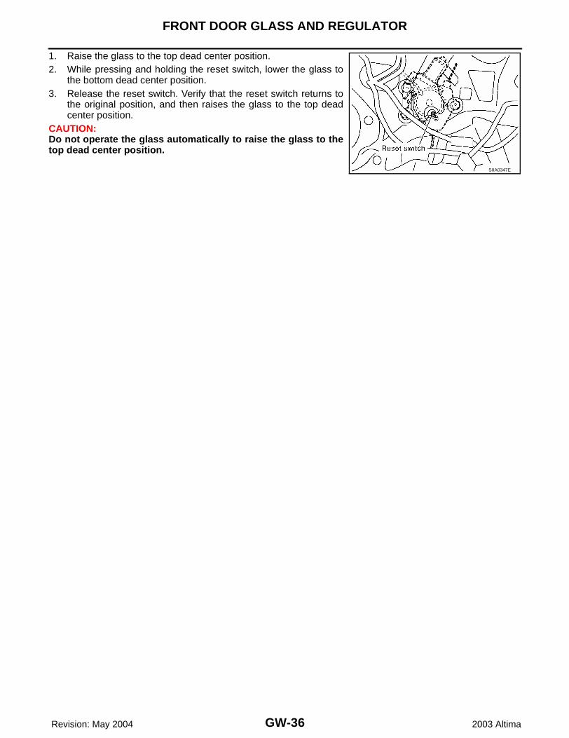
1. Raise the glass to the top dead center position.2. While pressing and holding the reset switch, lower the glass to
the bottom dead center position.3. Release the reset switch. Verify that the reset switch returns to
the original position, and then raises the glass to the top deadcenter position.
CAUTION:Do not operate the glass automatically to raise the glass to thetop dead center position.
SIIA0347E
REAR DOOR GLASS AND REGULATOR
GW-37
C
D
E
F
G
H
J
K
L
M
A
B
GW
Revision: May 2004 2003 Altima
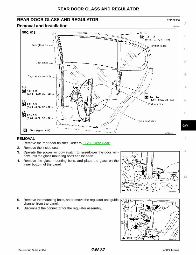
REAR DOOR GLASS AND REGULATOR PFP:82300
Removal and Installation EIS001B0
REMOVAL1. Remove the rear door finisher. Refer to EI-28, "Rear Door" .2. Remove the inside seal.3. Operate the power window switch to raise/lower the door win-
dow until the glass mounting bolts can be seen.4. Remove the glass mounting bolts, and place the glass on the
inner bottom of the panel.
5. Remove the mounting bolts, and remove the regulator and guidechannel from the panel.
6. Disconnect the connector for the regulator assembly.
LIIA0022E
SIIA0290E
SIIA0291E
GW-38
REAR DOOR GLASS AND REGULATOR
Revision: May 2004 2003 Altima
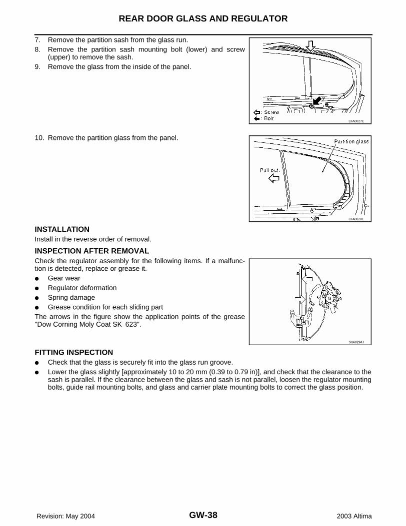
7. Remove the partition sash from the glass run.8. Remove the partition sash mounting bolt (lower) and screw
(upper) to remove the sash.9. Remove the glass from the inside of the panel.
10. Remove the partition glass from the panel.
INSTALLATIONInstall in the reverse order of removal.
INSPECTION AFTER REMOVALCheck the regulator assembly for the following items. If a malfunc-tion is detected, replace or grease it.● Gear wear● Regulator deformation● Spring damage● Grease condition for each sliding partThe arrows in the figure show the application points of the grease"Dow Corning Moly Coat SK 623".
FITTING INSPECTION● Check that the glass is securely fit into the glass run groove.● Lower the glass slightly [approximately 10 to 20 mm (0.39 to 0.79 in)], and check that the clearance to the
sash is parallel. If the clearance between the glass and sash is not parallel, loosen the regulator mountingbolts, guide rail mounting bolts, and glass and carrier plate mounting bolts to correct the glass position.
LIIA0027E
LIIA0028E
SIIA0294J
INSIDE MIRROR
GW-39
C
D
E
F
G
H
J
K
L
M
A
B
GW
Revision: May 2004 2003 Altima
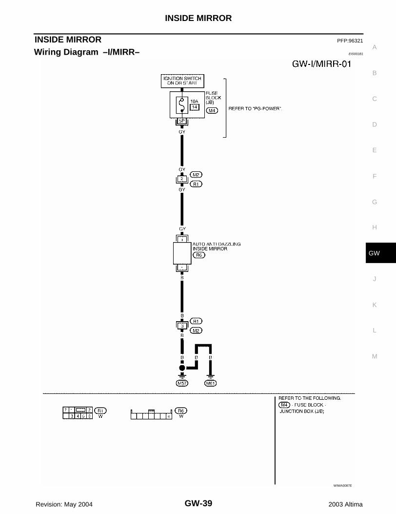
INSIDE MIRROR PFP:96321
Wiring Diagram –I/MIRR– EIS001B1
WIWA0087E
GW-40
INSIDE MIRROR
Revision: May 2004 2003 Altima
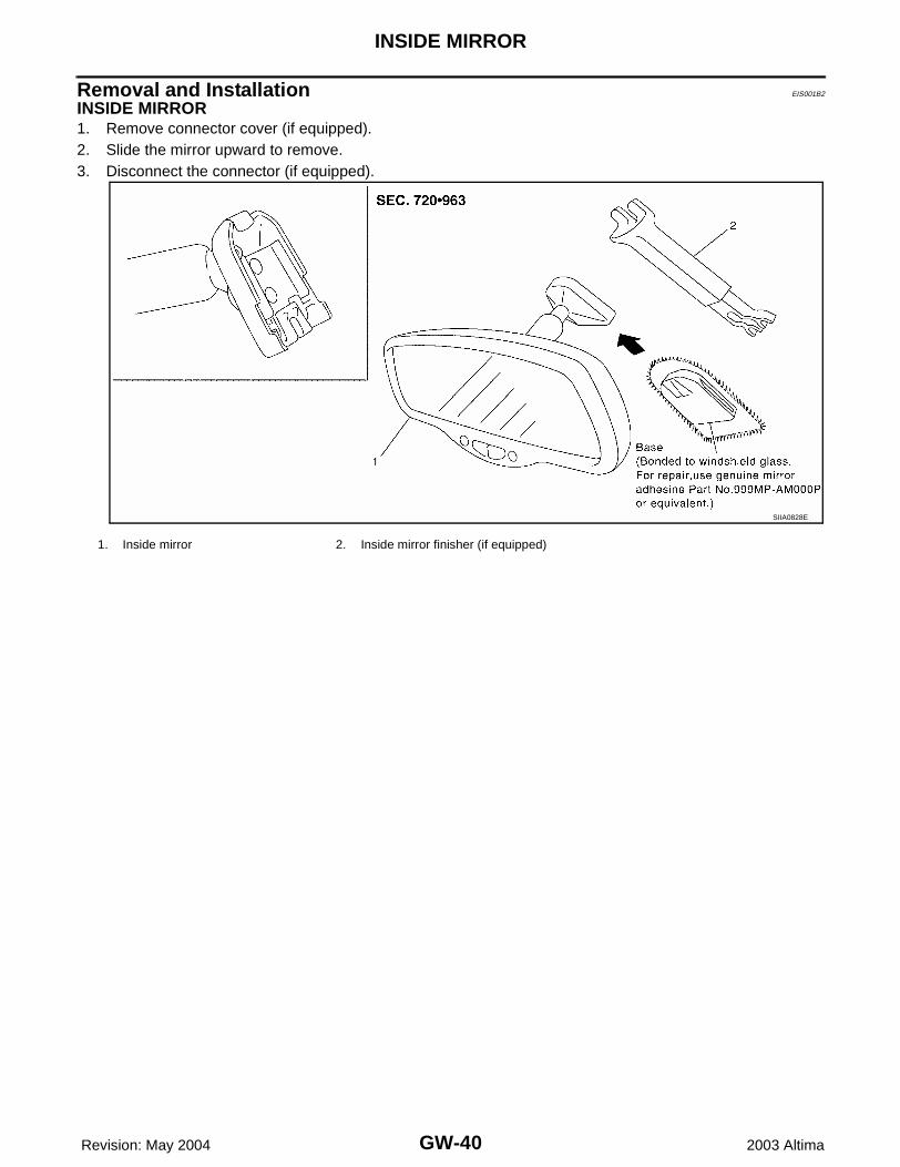
Removal and Installation EIS001B2
INSIDE MIRROR1. Remove connector cover (if equipped).2. Slide the mirror upward to remove.3. Disconnect the connector (if equipped).
1. Inside mirror 2. Inside mirror finisher (if equipped)
SIIA0828E
REAR WINDOW DEFOGGER
GW-41
C
D
E
F
G
H
J
K
L
M
A
B
GW
Revision: May 2004 2003 Altima
REAR WINDOW DEFOGGER PFP:25350
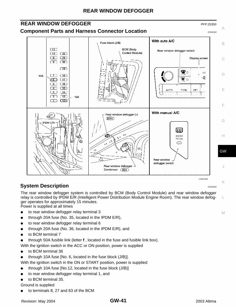
Component Parts and Harness Connector Location EIS001B3
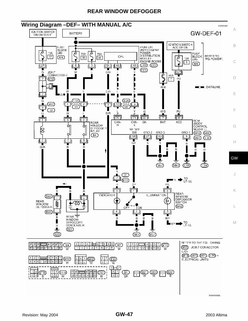
System Description EIS001B4
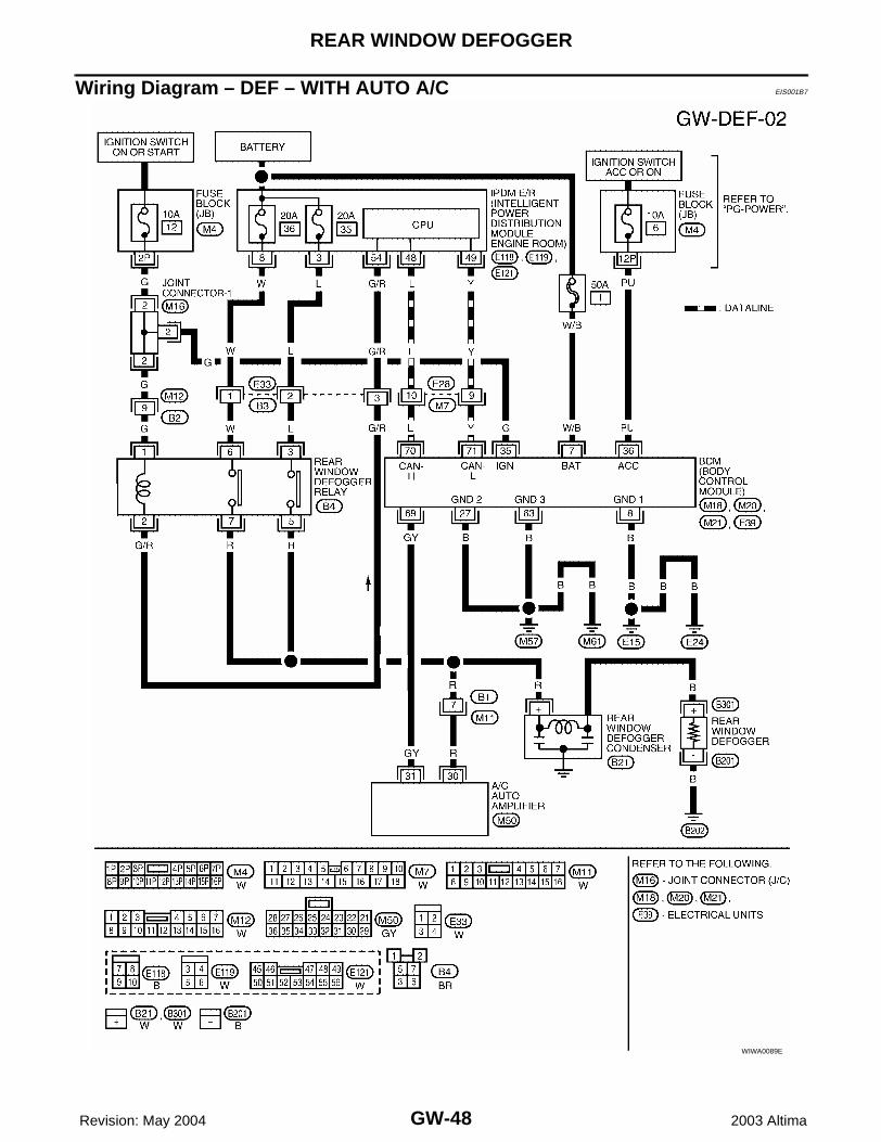
The rear window defogger system is controlled by BCM (Body Control Module) and rear window defoggerrelay is controlled by IPDM E/R (Intelligent Power Distribution Module Engine Room). The rear window defog-ger operates for approximately 15 minutes.Power is supplied at all times● to rear window defogger relay terminal 3● through 20A fuse (No. 35, located in the IPDM E/R),● to rear window defogger relay terminal 6● through 20A fuse (No. 36, located in the IPDM E/R), and● to BCM terminal 7● through 50A fusible link (letter f , located in the fuse and fusible link box).With the ignition switch in the ACC or ON position, power is supplied● to BCM terminal 36● through 10A fuse [No. 6, located in the fuse block (J/B)].With the ignition switch in the ON or START position, power is supplied● through 10A fuse [No.12, located in the fuse block (J/B)]● to rear window defogger relay terminal 1, and● to BCM terminal 35.Ground is supplied● to terminals 8, 27 and 63 of the BCM
LIIA0103E
GW-42
REAR WINDOW DEFOGGER
Revision: May 2004 2003 Altima
● through body grounds E15, E24, M57 and M61, and● to rear window defogger terminal –● through body ground B202.With manual A/C, ground is also supplied● to terminals 2 and 4 of the rear window defogger switch● through body grounds M57 and M61.BCM is connected to IPDM E/R as DATA LINE (CAN H line and CAN L line).When the rear window defogger switch is turned ON, ground is supplied● to BCM terminal 69● through terminal 1 of the rear window defogger switch (with manual A/C), or● through terminal 31 of the A/C auto amplifier (with auto A/C).BCM outputs rear window defogger switch signal to IPDM E/R via DATA LINE (CAN H line and CAN L line).Ground is then supplied to Terminal 2 of the rear window defogger relay through IPDM E/R terminal 54.With power and ground supplied, the rear window defogger relay is energized.Power is supplied● through terminals 5 and 7 of the rear window defogger relay● to the rear window defogger, and● to terminal 3 of the rear window defogger switch (with manual A/C), or● to terminal 30 of the A/C auto amplifier (with auto A/C).The rear window defogger has an independent ground.With power and ground supplied, the rear window defogger filaments heat and defog the rear window.When the system is activated, the rear window defogger indicator illuminates in the rear window defoggerswitch.
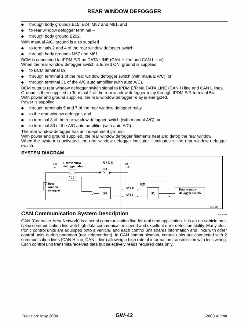
SYSTEM DIAGRAM
CAN Communication System Description EIS001B5
CAN (Controller Area Network) is a serial communication line for real time application. It is an on-vehicle mul-tiplex communication line with high data communication speed and excellent error detection ability. Many elec-tronic control units are equipped onto a vehicle, and each control unit shares information and links with othercontrol units during operation (not independent). In CAN communication, control units are connected with 2communication lines (CAN H line, CAN L line) allowing a high rate of information transmission with less wiring.Each control unit transmits/receives data but selectively reads required data only.
LIIA0164E
REAR WINDOW DEFOGGER
GW-43
C
D
E
F
G
H
J
K
L
M
A
B
GW
Revision: May 2004 2003 Altima
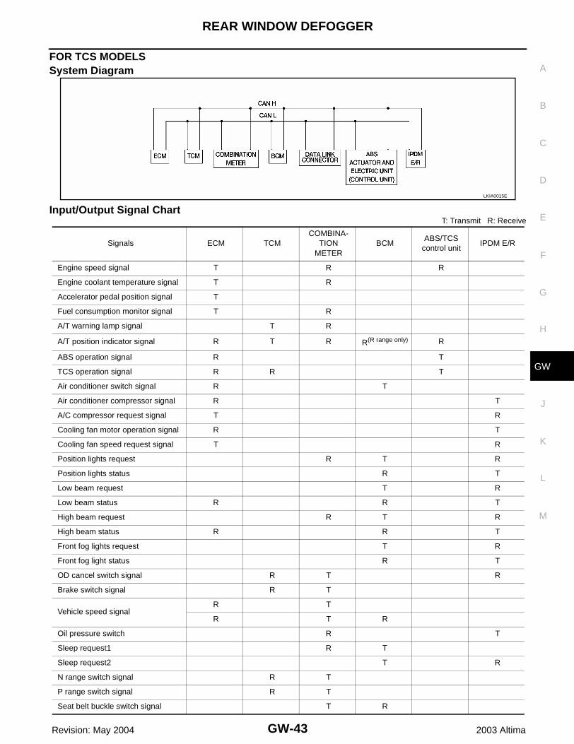
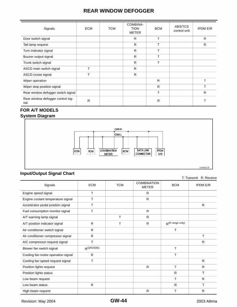
FOR TCS MODELSSystem Diagram
Input/Output Signal ChartT: Transmit R: Receive
LKIA0015E
Signals ECM TCMCOMBINA-
TION METER
BCMABS/TCS
control unitIPDM E/R
Engine speed signal T R R
Engine coolant temperature signal T R
Accelerator pedal position signal T
Fuel consumption monitor signal T R
A/T warning lamp signal T R
A/T position indicator signal R T R R(R range only) R
ABS operation signal R T
TCS operation signal R R T
Air conditioner switch signal R T
Air conditioner compressor signal R T
A/C compressor request signal T R
Cooling fan motor operation signal R T
Cooling fan speed request signal T R
Position lights request R T R
Position lights status R T
Low beam request T R
Low beam status R R T
High beam request R T R
High beam status R R T
Front fog lights request T R
Front fog light status R T
OD cancel switch signal R T R
Brake switch signal R T
Vehicle speed signalR T
R T R
Oil pressure switch R T
Sleep request1 R T
Sleep request2 T R
N range switch signal R T
P range switch signal R T
Seat belt buckle switch signal T R
GW-44
REAR WINDOW DEFOGGER
Revision: May 2004 2003 Altima
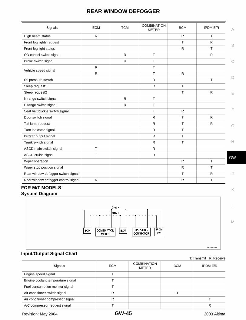
FOR A/T MODELSSystem Diagram
Input/Output Signal ChartT: Transmit R: Receive
Door switch signal R T R
Tail lamp request R T R
Turn indicator signal R T
Buzzer output signal R T
Trunk switch signal R T
ASCD main switch signal T R
ASCD cruise signal T R
Wiper operation R T
Wiper stop position signal R T
Rear window defogger switch signal T R
Rear window defogger control sig-nal
R R T
Signals ECM TCMCOMBINA-
TION METER
BCMABS/TCS
control unitIPDM E/R
LKIA0017E
Signals ECM TCMCOMBINATION
METERBCM IPDM E/R
Engine speed signal T R
Engine coolant temperature signal T R
Accelerator pedal position signal T R
Fuel consumption monitor signal T R
A/T warning lamp signal T R
A/T position indicator signal R T R R(R range only)
Air conditioner switch signal R T
Air conditioner compressor signal R T
A/C compressor request signal T R
Blower fan switch signal R(QR25DE) T
Cooling fan motor operation signal R T
Cooling fan speed request signal T R
Position lights request R T R
Position lights status R T
Low beam request T R
Low beam status R R T
High beam request R T R
REAR WINDOW DEFOGGER
GW-45
C
D
E
F
G
H
J
K
L
M
A
B
GW
Revision: May 2004 2003 Altima
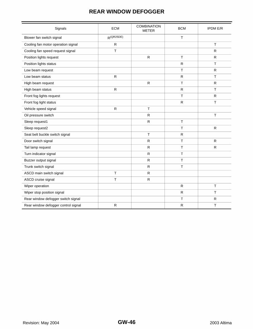
FOR M/T MODELSSystem Diagram
Input/Output Signal ChartT: Transmit R: Receive
High beam status R R T
Front fog lights request T R
Front fog light status R T
OD cancel switch signal R T R
Brake switch signal R T
Vehicle speed signalR T
R T R
Oil pressure switch R T
Sleep request1 R T
Sleep request2 T R
N range switch signal R T
P range switch signal R T
Seat belt buckle switch signal T R
Door switch signal R T R
Tail lamp request R T R
Turn indicator signal R T
Buzzer output signal R T
Trunk switch signal R T
ASCD main switch signal T R
ASCD cruise signal T R
Wiper operation R T
Wiper stop position signal R T
Rear window defogger switch signal T R
Rear window defogger control signal R R T
Signals ECM TCMCOMBINATION
METERBCM IPDM E/R
LKIA0018E
Signals ECMCOMBINATION
METERBCM IPDM E/R
Engine speed signal T
Engine coolant temperature signal T
Fuel consumption monitor signal T
Air conditioner switch signal R T
Air conditioner compressor signal R T
A/C compressor request signal T R
GW-46
REAR WINDOW DEFOGGER
Revision: May 2004 2003 Altima
Blower fan switch signal R(QR25DE) T
Cooling fan motor operation signal R T
Cooling fan speed request signal T R
Position lights request R T R
Position lights status R T
Low beam request T R
Low beam status R R T
High beam request R T R
High beam status R R T
Front fog lights request T R
Front fog light status R T
Vehicle speed signal R T
Oil pressure switch R T
Sleep request1 R T
Sleep request2 T R
Seat belt buckle switch signal T R
Door switch signal R T R
Tail lamp request R T R
Turn indicator signal R T
Buzzer output signal R T
Trunk switch signal R T
ASCD main switch signal T R
ASCD cruise signal T R
Wiper operation R T
Wiper stop position signal R T
Rear window defogger switch signal T R
Rear window defogger control signal R R T
Signals ECMCOMBINATION
METERBCM IPDM E/R
REAR WINDOW DEFOGGER
GW-47
C
D
E
F
G
H
J
K
L
M
A
B
GW
Revision: May 2004 2003 Altima
Wiring Diagram –DEF– WITH MANUAL A/C EIS001B6
WIWA0088E
GW-48
REAR WINDOW DEFOGGER
Revision: May 2004 2003 Altima
Wiring Diagram – DEF – WITH AUTO A/C EIS001B7
WIWA0089E
REAR WINDOW DEFOGGER
GW-49
C
D
E
F
G
H
J
K
L
M
A
B
GW
Revision: May 2004 2003 Altima
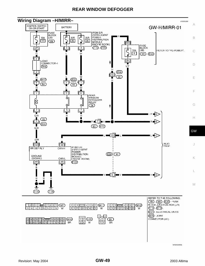
Wiring Diagram –H/MIRR– EIS001B8
WIWA0090E
GW-50
REAR WINDOW DEFOGGER
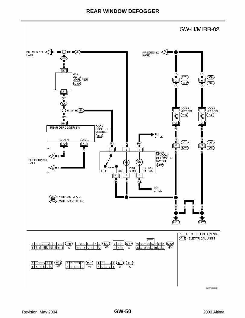
Revision: May 2004 2003 Altima
WIWA0091E
REAR WINDOW DEFOGGER
GW-51
C
D
E
F
G
H
J
K
L
M
A
B
GW
Revision: May 2004 2003 Altima
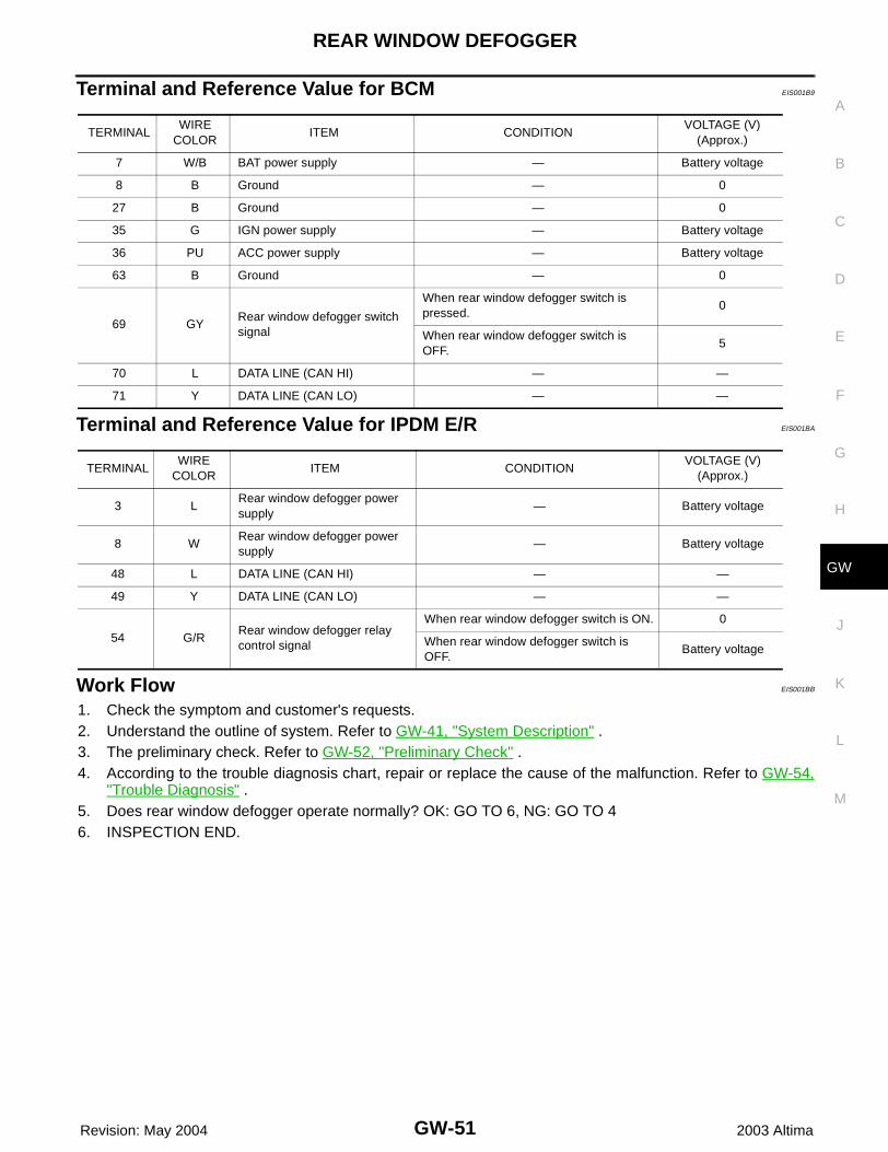
Terminal and Reference Value for BCM EIS001B9
Terminal and Reference Value for IPDM E/R EIS001BA
Work Flow EIS001BB
1. Check the symptom and customer's requests.2. Understand the outline of system. Refer to GW-41, "System Description" .3. The preliminary check. Refer to GW-52, "Preliminary Check" .4. According to the trouble diagnosis chart, repair or replace the cause of the malfunction. Refer to GW-54,
"Trouble Diagnosis" .5. Does rear window defogger operate normally? OK: GO TO 6, NG: GO TO 46. INSPECTION END.
TERMINALWIRE
COLORITEM CONDITION
VOLTAGE (V)(Approx.)
7 W/B BAT power supply — Battery voltage
8 B Ground — 0
27 B Ground — 0
35 G IGN power supply — Battery voltage
36 PU ACC power supply — Battery voltage
63 B Ground — 0
69 GYRear window defogger switch signal
When rear window defogger switch is pressed.
0
When rear window defogger switch is OFF.
5
70 L DATA LINE (CAN HI) — —
71 Y DATA LINE (CAN LO) — —
TERMINALWIRE
COLORITEM CONDITION
VOLTAGE (V)(Approx.)
3 LRear window defogger power supply
— Battery voltage
8 WRear window defogger power supply
— Battery voltage
48 L DATA LINE (CAN HI) — —
49 Y DATA LINE (CAN LO) — —
54 G/RRear window defogger relay control signal
When rear window defogger switch is ON. 0
When rear window defogger switch is OFF.
Battery voltage
GW-52
REAR WINDOW DEFOGGER
Revision: May 2004 2003 Altima
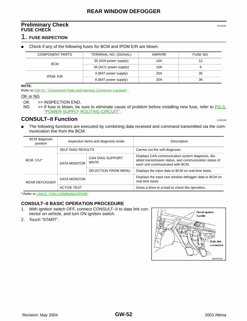
Preliminary Check EIS001BC
FUSE CHECK
1. FUSE INSPECTION
● Check if any of the following fuses for BCM and IPDM E/R are blown.
NOTE:Refer to GW-41, "Component Parts and Harness Connector Location" .
OK or NGOK >> INSPECTION END.NG >> If fuse is blown, be sure to eliminate cause of problem before installing new fuse, refer to PG-3,
"POWER SUPPLY ROUTING CIRCUIT" .
CONSULT–II Function EIS001BD
● The following functions are executed by combining data received and command transmitted via the com-munication line from the BCM.
*:Refer to LAN-3, "CAN COMMUNICATION" .
CONSULT–II BASIC OPERATION PROCEDURE1. With ignition switch OFF, connect CONSULT–II to data link con-
nector on vehicle, and turn ON ignition switch.2. Touch “START”.
COMPONENT PARTS TERMINAL NO. (SIGNAL) AMPERE FUSE NO.
BCM35 (IGN power supply) 10A 12
36 (ACC power supply) 10A 6
IPDM E/R3 (BAT power supply) 20A 35
8 (BAT power supply) 20A 36
BCM diagnosis position
Inspection items and diagnosis mode Description
BCM C/U*
SELF DIAG RESULTS Carries out the self-diagnosis.
DATA MONITOR
CAN DIAG SUPPORT MNTR
Displays CAN communication system diagnosis, dis-abled transmission status, and communication status of each unit communicated with BCM.
SELECTION FROM MENU Displays the input data to BCM on real-time basis.
REAR DEFOGGERDATA MONITOR
Displays the input rear window defogger data to BCM on real-time basis.
ACTIVE TEST Gives a drive to a load to check the operation.
BBIA0002E
REAR WINDOW DEFOGGER
GW-53
C
D
E
F
G
H
J
K
L
M
A
B
GW
Revision: May 2004 2003 Altima
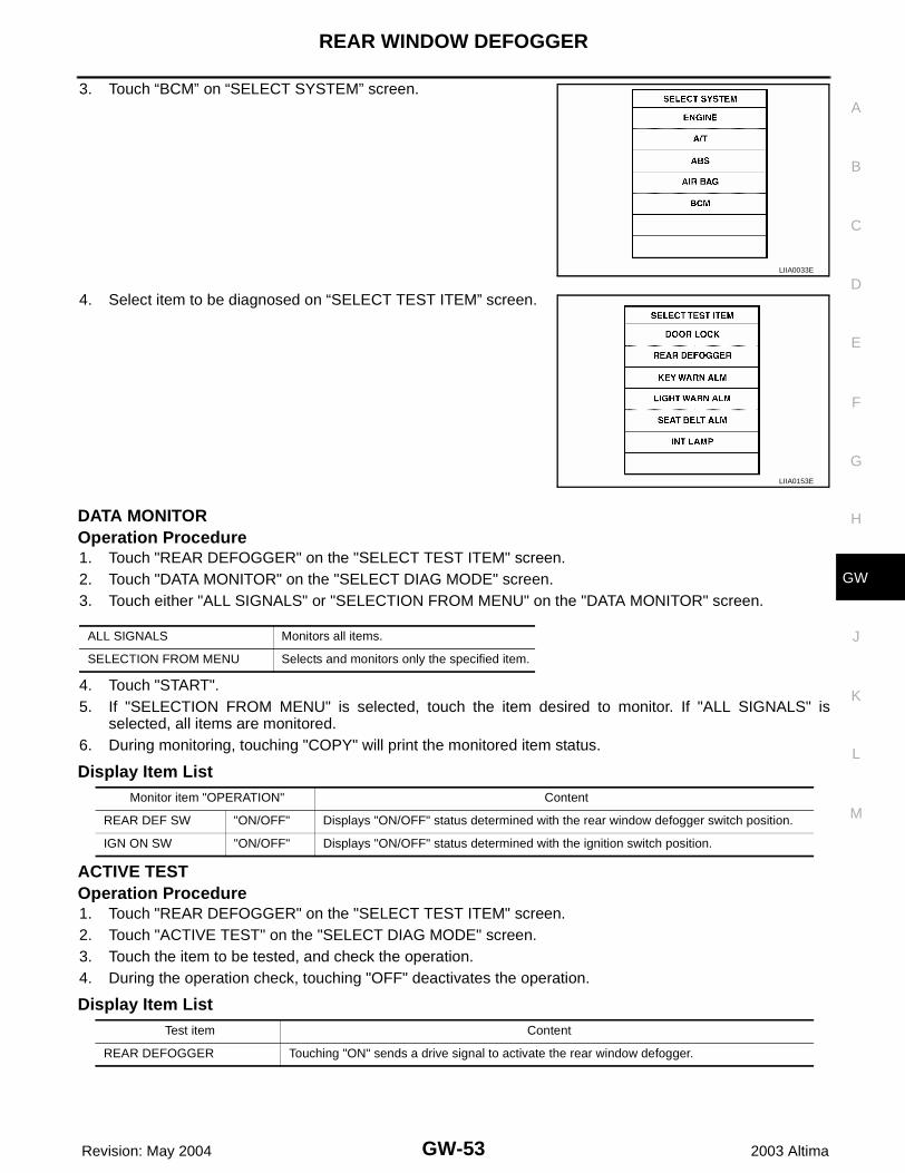
3. Touch “BCM” on “SELECT SYSTEM” screen.
4. Select item to be diagnosed on “SELECT TEST ITEM” screen.
DATA MONITOROperation Procedure1. Touch "REAR DEFOGGER" on the "SELECT TEST ITEM" screen.2. Touch "DATA MONITOR" on the "SELECT DIAG MODE" screen.3. Touch either "ALL SIGNALS" or "SELECTION FROM MENU" on the "DATA MONITOR" screen.
4. Touch "START".5. If "SELECTION FROM MENU" is selected, touch the item desired to monitor. If "ALL SIGNALS" is
selected, all items are monitored.6. During monitoring, touching "COPY" will print the monitored item status.
Display Item List
ACTIVE TESTOperation Procedure1. Touch "REAR DEFOGGER" on the "SELECT TEST ITEM" screen.2. Touch "ACTIVE TEST" on the "SELECT DIAG MODE" screen.3. Touch the item to be tested, and check the operation.4. During the operation check, touching "OFF" deactivates the operation.
Display Item List
LIIA0033E
LIIA0153E
ALL SIGNALS Monitors all items.
SELECTION FROM MENU Selects and monitors only the specified item.
Monitor item "OPERATION" Content
REAR DEF SW "ON/OFF" Displays "ON/OFF" status determined with the rear window defogger switch position.
IGN ON SW "ON/OFF" Displays "ON/OFF" status determined with the ignition switch position.
Test item Content
REAR DEFOGGER Touching "ON" sends a drive signal to activate the rear window defogger.
GW-54
REAR WINDOW DEFOGGER
Revision: May 2004 2003 Altima
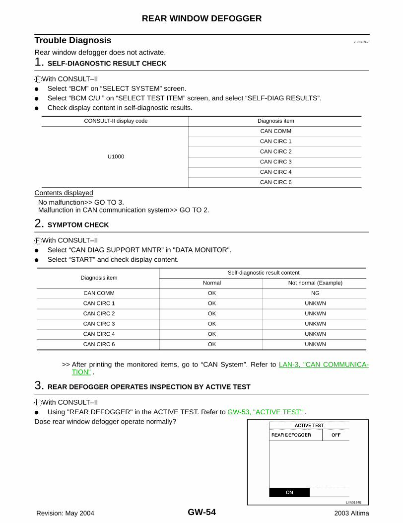
Trouble Diagnosis EIS001BE
Rear window defogger does not activate.
1. SELF-DIAGNOSTIC RESULT CHECK
With CONSULT–II● Select “BCM” on “SELECT SYSTEM” screen.● Select “BCM C/U ” on “SELECT TEST ITEM” screen, and select “SELF-DIAG RESULTS”.● Check display content in self-diagnostic results.
Contents displayedNo malfunction>> GO TO 3.Malfunction in CAN communication system>> GO TO 2.
2. SYMPTOM CHECK
With CONSULT–II● Select “CAN DIAG SUPPORT MNTR” in "DATA MONITOR".● Select “START” and check display content.
>> After printing the monitored items, go to “CAN System”. Refer to LAN-3, "CAN COMMUNICA-TION" .
3. REAR DEFOGGER OPERATES INSPECTION BY ACTIVE TEST
With CONSULT–II● Using "REAR DEFOGGER" in the ACTIVE TEST. Refer to GW-53, "ACTIVE TEST" .Dose rear window defogger operate normally?
CONSULT-II display code Diagnosis item
U1000
CAN COMM
CAN CIRC 1
CAN CIRC 2
CAN CIRC 3
CAN CIRC 4
CAN CIRC 6
Diagnosis itemSelf-diagnostic result content
Normal Not normal (Example)
CAN COMM OK NG
CAN CIRC 1 OK UNKWN
CAN CIRC 2 OK UNKWN
CAN CIRC 3 OK UNKWN
CAN CIRC 4 OK UNKWN
CAN CIRC 6 OK UNKWN
LIIA0154E
REAR WINDOW DEFOGGER
GW-55
C
D
E
F
G
H
J
K
L
M
A
B
GW
Revision: May 2004 2003 Altima
OK or NGOK >> GO TO 4.NG >> GO TO 6.
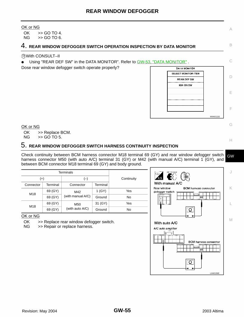
4. REAR WINDOW DEFOGGER SWITCH OPERATION INSPECTION BY DATA MONITOR
With CONSULT–II● Using "REAR DEF SW" in the DATA MONITOR". Refer to GW-53, "DATA MONITOR" .Dose rear window defogger switch operate properly?
OK or NGOK >> Replace BCM.NG >> GO TO 5.
5. REAR WINDOW DEFOGGER SWITCH HARNESS CONTINUITY INSPECTION
Check continuity between BCM harness connector M18 terminal 69 (GY) and rear window defogger switchharness connector M50 (with auto A/C) terminal 31 (GY) or M42 (with manual A/C) terminal 1 (GY), andbetween BCM connector M18 terminal 69 (GY) and body ground.
OK or NGOK >> Replace rear window defogger switch.NG >> Repair or replace harness.
WIIA0111E
Terminals
Continuity(+) (–)
Connector Terminal Connector Terminal
M1869 (GY) M42
(with manual A/C)
1 (GY) Yes
69 (GY) Ground No
M1869 (GY) M50
(with auto A/C)
31 (GY) Yes
69 (GY) Ground No
LIIA0156E
GW-56
REAR WINDOW DEFOGGER
Revision: May 2004 2003 Altima
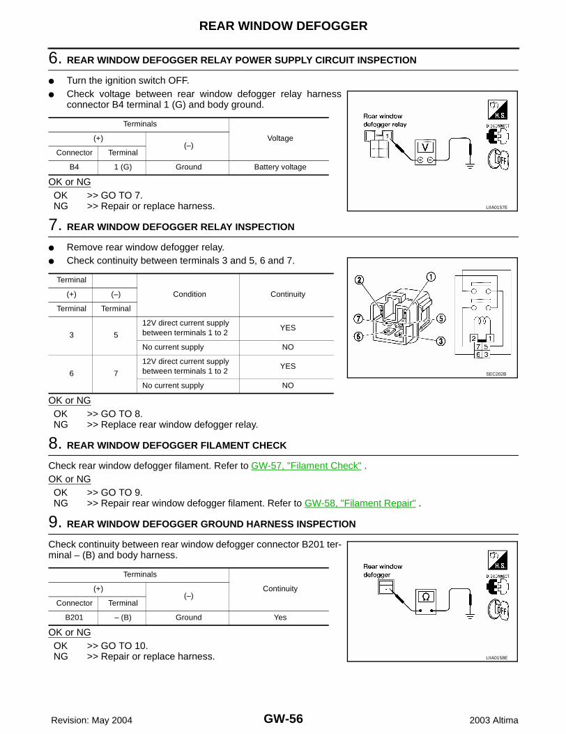
6. REAR WINDOW DEFOGGER RELAY POWER SUPPLY CIRCUIT INSPECTION
● Turn the ignition switch OFF.● Check voltage between rear window defogger relay harness
connector B4 terminal 1 (G) and body ground.
OK or NGOK >> GO TO 7.NG >> Repair or replace harness.
7. REAR WINDOW DEFOGGER RELAY INSPECTION
● Remove rear window defogger relay.● Check continuity between terminals 3 and 5, 6 and 7.
OK or NGOK >> GO TO 8.NG >> Replace rear window defogger relay.
8. REAR WINDOW DEFOGGER FILAMENT CHECK
Check rear window defogger filament. Refer to GW-57, "Filament Check" .OK or NGOK >> GO TO 9.NG >> Repair rear window defogger filament. Refer to GW-58, "Filament Repair" .
9. REAR WINDOW DEFOGGER GROUND HARNESS INSPECTION
Check continuity between rear window defogger connector B201 ter-minal – (B) and body harness.
OK or NGOK >> GO TO 10.NG >> Repair or replace harness.
Terminals
Voltage(+)(–)
Connector Terminal
B4 1 (G) Ground Battery voltage
LIIA0157E
Terminal
Condition Continuity(+) (–)
Terminal Terminal
3 5
12V direct current supply between terminals 1 to 2
YES
No current supply NO
6 7
12V direct current supply between terminals 1 to 2
YES
No current supply NO
SEC202B
Terminals
Continuity(+)(–)
Connector Terminal
B201 – (B) Ground Yes
LIIA0158E
REAR WINDOW DEFOGGER
GW-57
C
D
E
F
G
H
J
K
L
M
A
B
GW
Revision: May 2004 2003 Altima
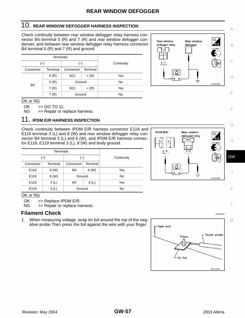
10. REAR WINDOW DEFOGGER HARNESS INSPECTION
Check continuity between rear window defogger relay harness con-nector B4 terminal 5 (R) and 7 (R) and rear window defogger con-denser, and between rear window defogger relay harness connectorB4 terminal 5 (R) and 7 (R) and ground.
OK or NGOK >> GO TO 11.NG >> Repair or replace harness.
11. IPDM E/R HARNESS INSPECTION
Check continuity between IPDM E/R harness connector E118 andE119 terminal 3 (L) and 8 (W) and rear window defogger relay con-nector B4 terminal 3 (L) and 6 (W), and IPDM E/R harness connec-tor E118, E119 terminal 3 (L), 8 (W) and body ground.
OK or NGOK >> Replace IPDM E/R.NG >> Repair or replace harness.
Filament Check EIS001BF
1. When measuring voltage, wrap tin foil around the top of the neg-ative probe.Then press the foil against the wire with your finger.
Terminals
Continuity(+) (–)
Connector Terminal Connector Terminal
B4
5 (R) B21 + (R) Yes
5 (R) Ground No
7 (R) B21 + (R) Yes
7 (R) Ground No
LIIA0159E
Terminals
Continuity(+) (–)
Connector Terminal Connector Terminal
E118 8 (W) B4 6 (W) Yes
E118 8 (W) Ground No
E119 3 (L) B4 3 (L) Yes
E119 3 (L) Ground No
LIIA0160E
SEL122R
GW-58
REAR WINDOW DEFOGGER
Revision: May 2004 2003 Altima
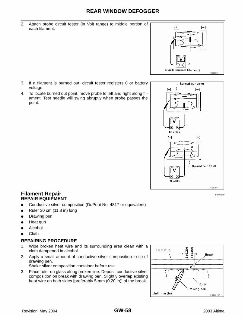
2. Attach probe circuit tester (in Volt range) to middle portion ofeach filament.
3. If a filament is burned out, circuit tester registers 0 or batteryvoltage.
4. To locate burned out point, move probe to left and right along fil-ament. Test needle will swing abruptly when probe passes thepoint.
Filament Repair EIS001BG
REPAIR EQUIPMENT● Conductive silver composition (DuPont No. 4817 or equivalent)● Ruler 30 cm (11.8 in) long● Drawing pen● Heat gun● Alcohol● Cloth
REPAIRING PROCEDURE1. Wipe broken heat wire and its surrounding area clean with a
cloth dampened in alcohol.2. Apply a small amount of conductive silver composition to tip of
drawing pen.Shake silver composition container before use.
3. Place ruler on glass along broken line. Deposit conductive silvercomposition on break with drawing pen. Slightly overlap existingheat wire on both sides [preferably 5 mm (0.20 in)] of the break.
SEL263
SEL265
PIIA0215E
REAR WINDOW DEFOGGER
GW-59
C
D
E
F
G
H
J
K
L
M
A
B
GW
Revision: May 2004 2003 Altima
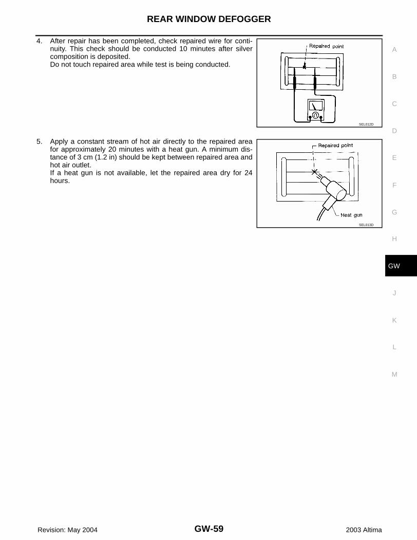
4. After repair has been completed, check repaired wire for conti-nuity. This check should be conducted 10 minutes after silvercomposition is deposited.Do not touch repaired area while test is being conducted.
5. Apply a constant stream of hot air directly to the repaired areafor approximately 20 minutes with a heat gun. A minimum dis-tance of 3 cm (1.2 in) should be kept between repaired area andhot air outlet.If a heat gun is not available, let the repaired area dry for 24hours.
SEL012D
SEL013D
GW-60
DOOR MIRROR
Revision: May 2004 2003 Altima
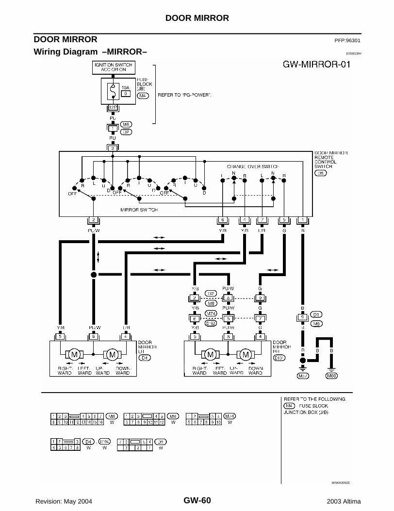
DOOR MIRROR PFP:96301
Wiring Diagram –MIRROR– EIS001BH
WIWA0092E
DOOR MIRROR
GW-61
C
D
E
F
G
H
J
K
L
M
A
B
GW
Revision: May 2004 2003 Altima
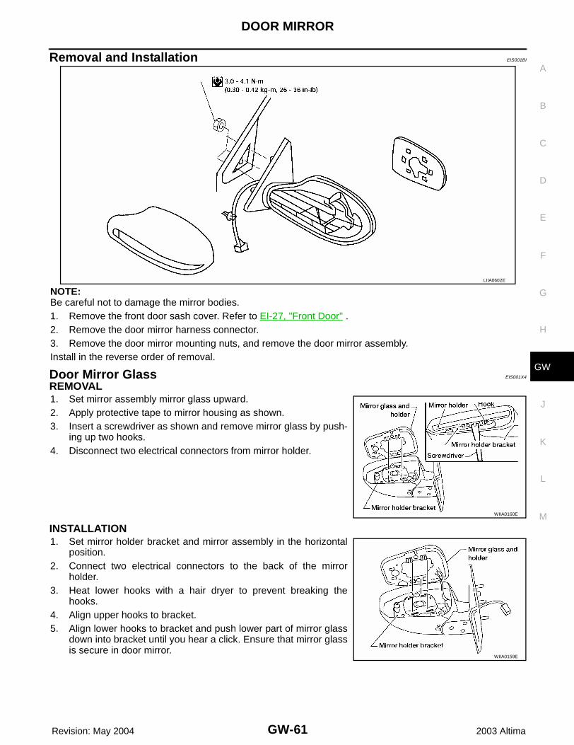
Removal and Installation EIS001BI
NOTE:Be careful not to damage the mirror bodies.1. Remove the front door sash cover. Refer to EI-27, "Front Door" .2. Remove the door mirror harness connector.3. Remove the door mirror mounting nuts, and remove the door mirror assembly.Install in the reverse order of removal.
Door Mirror Glass EIS001X4
REMOVAL1. Set mirror assembly mirror glass upward.2. Apply protective tape to mirror housing as shown.3. Insert a screwdriver as shown and remove mirror glass by push-
ing up two hooks.4. Disconnect two electrical connectors from mirror holder.
INSTALLATION1. Set mirror holder bracket and mirror assembly in the horizontal
position.2. Connect two electrical connectors to the back of the mirror
holder.3. Heat lower hooks with a hair dryer to prevent breaking the
hooks.4. Align upper hooks to bracket.5. Align lower hooks to bracket and push lower part of mirror glass
down into bracket until you hear a click. Ensure that mirror glassis secure in door mirror.
LIIA0602E
WIIA0160E
WIIA0159E

GW-62
DOOR MIRROR
Revision: May 2004 2003 Altima