Embed Size (px)
Citation preview

a
2006-2011 C6 Z06 Corvette High Output Intercooled System
Installation Guide
The Intercooled Supercharging Experts!®
®
© 2007 Accessible Technologies, Inc.
Accessible Technologies, Inc. 14801 W. 114th Terrace
Lenexa, KS 66215 Phone: 913.338.2886
Fax: 913.338.2879 [email protected]
All rights reserved. Accessible Technologies Inc. hereby grants permission to use and reproduce this document for personal use, provided that all copyright information be retained. Reproduction of this document for unauthorized commercial use is strictly prohibited.
Information in this document is subject to change without notice.
ProCharger is a registered trademark and The Intercooled Supercharging Experts!TM and Designed to Blow Away the CompetitionTM are trademarks of Accessible Technologies, Inc. and may not be used without express permission.
Revised 5/10 Part Number PMGP1A-002 Rev. G Printed in the USA
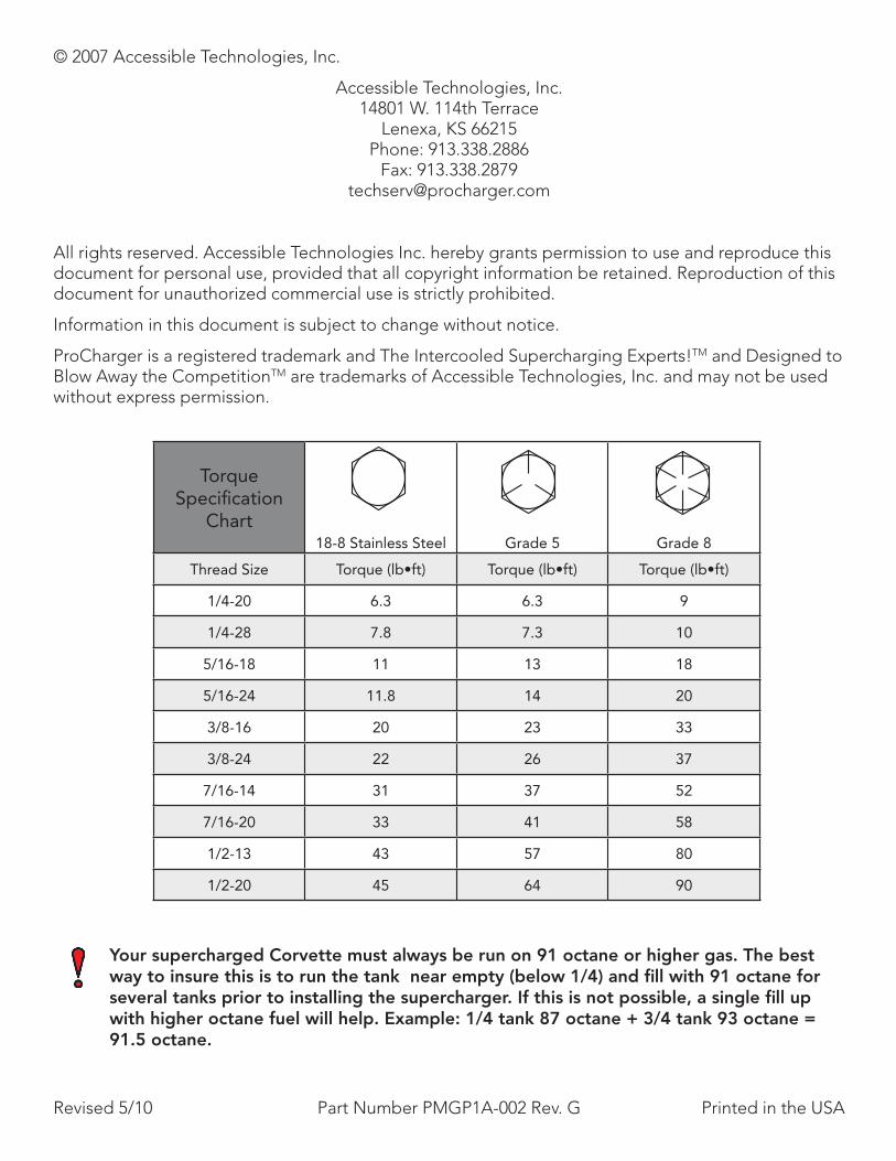
Torque Specification
Chart18-8 Stainless Steel Grade 5 Grade 8
Thread Size Torque (lb•ft) Torque (lb•ft) Torque (lb•ft)
1/4-20 6.3 6.3 9
1/4-28 7.8 7.3 10
5/16-18 11 13 18
5/16-24 11.8 14 20
3/8-16 20 23 33
3/8-24 22 26 37
7/16-14 31 37 52
7/16-20 33 41 58
1/2-13 43 57 80
1/2-20 45 64 90
Your supercharged Corvette must always be run on 91 octane or higher gas. The best way to insure this is to run the tank near empty (below 1/4) and fill with 91 octane for several tanks prior to installing the supercharger. If this is not possible, a single fill up with higher octane fuel will help. Example: 1/4 tank 87 octane + 3/4 tank 93 octane = 91.5 octane.
Introduction
2006-2011 C6 Z06 Corvette H.O. System Installation Guide i
Congratulations on purchasing your ProCharger® C6 Z06 Corvette High Output Intercooled System. For best results, we recommend reviewing the installation instructions beforehand, and following the installation instructions closely and in sequence. A detailed packing list has been provided to assist you in identifying the components of your ProCharger system. If you have any questions regarding any aspect of this installation, call us at (913) 338-3086.
Warning: Failure to comply with instructions in this manual could result in personal injury, property damage, and/or voiding your warranty.
Required Tools and Supplies• 3/8” & 1/2” Socket Sets (standard & metric) • 1/2” Impact Gun & Sockets • C-Clip Pliers • 1/2” Breaker Bar & 4” Extention • #20 Torx Wrench • Open End Wrench Set (standard & metric) • Dex-Cool Coolant • 3/8” Hex Bit Set (allen head) • Flat & Phillips Screwdrivers • Plier Set• Propane Torch • 1/2” Torque Wrench • Adjustible Wrench • Utility Knife • Drill
IntroductIon
You should also have the following gauges available to properly check the finished installation and monitor your vehicle’s performance (especially for testing):• Manifold Boost Pressure Gauge • Fuel Pressure Gauge • Wide Band Oxygen Sensor and Gauge
Gauges should be of a type that can be read from the cockpit while performing a wide-open throttle road test. Cockpit or hood-mounted gauges are preferable. In order to obtain usable readings, the gauges should measure pressure at the intake manifold and fuel rail. IF VEHICLE DOES NOT MAINTAIN PROPER FUEL PRESSURE, DECREASE THROTTLE APPLICATION IMMEDIATELY. In some cases, extra vehicle modifications can strain the stock fuel pump. If your vehicle has difficulty retaining adequate fuel pressure, contact ATI ProCharger about the availability of an upgraded fuel system.
The engine on which the ProCharger® is to be installed should retain the factory compression ratio. If it has been modified in any way, please consult ProCharger staff before proceeding with the installation. This supercharger system is intended for use on STOCK, strong, well-maintained engines/transmissions. Installation on a worn or troublesome powertrain should be reconsidered. ATI PROCHARGER WILL NOT BE HELD RESPONSIBLE FOR DAMAGE TO A VEHICLE’S POWERTRAIN. ATI ProCharger is not responsible for ECM tuning/programming on non-stock vehicles. ATI PROCHARGER recommends verifying that your vehicle has current ECM updates from the vehicle manufacturer before installation.
For best performance and reliability, always use premium grade fuel (91 octane or higher) and listen closely for signs of detonation, which might sound like ball bearings rolling around in a tin can. IF DETONATION SHOULD OCCUR, OR IF YOU ARE UNSURE WHETHER WHAT YOU’RE HEARING IS DETONATION, DECREASE THROTTLE APPLICATION IMMEDIATELY and please consult ATI ProCharger staff. Detonation should not be an issue with a properly installed intercooled supercharger system, though OEM factory-shipped engine and parts inconsistencies are possible on any vehicle.
Introduction
ii C6 Z06 Corvette H.O. System Installation Guide
table of contents
Introduction .................................................................................................................................. i
Table of Contents ..........................................................................................................................ii
Getting Started ............................................................................................................................ 2
Harmonic Balancer ....................................................................................................................... 4
Front Fascia ................................................................................................................................. 8
Radiator/Oil Cooler ...................................................................................................................... 9
Coolant Hose Modification ........................................................................................................ 13
ProCharger Installation .............................................................................................................. 14
Intercooler and Tubing Installation ............................................................................................ 20
Fuel Injector Replacement ......................................................................................................... 25
Vacuum Manifold Installation ..................................................................................................... 27
Final Assembly ........................................................................................................................... 28
Tuning ........................................................................................................................................ 30
Supplemental Notes .................................................................................................................. 32
Installation Review and Safety Check ........................................................................................ 33
Operation and Maintenance ...................................................................................................... 34
Limited Warranty ....................................................................................................................... 36
Procharger Extended Coverage ................................................................................................. 37
Notes ......................................................................................................................................... 38
Introduction
C6 Z06 Corvette H.O. System Installation Guide 1
IMPORTANT TUNING NOTE
For complete system installations, please review the tuning section of this manual to ensure you have the proper components to complete the installation. Tuning for certain model years of the Corvette Z06 is a multi-step process that should be initialized before the installation has begun. If there are any questions about this process, or any other step during your installation, please call ProCharger Technical Service at 913-338-2886.
Getting Started
2 2006-2011 C6 Z06 Corvette H.O. System Installation Guide
1 Disconnect the negative battery cable from the battery. The battery is located in the rear hatch.
2 Remove the driver’s and passenger’s side plastic engine covers by pulling firmly up-ward. Set the covers aside.
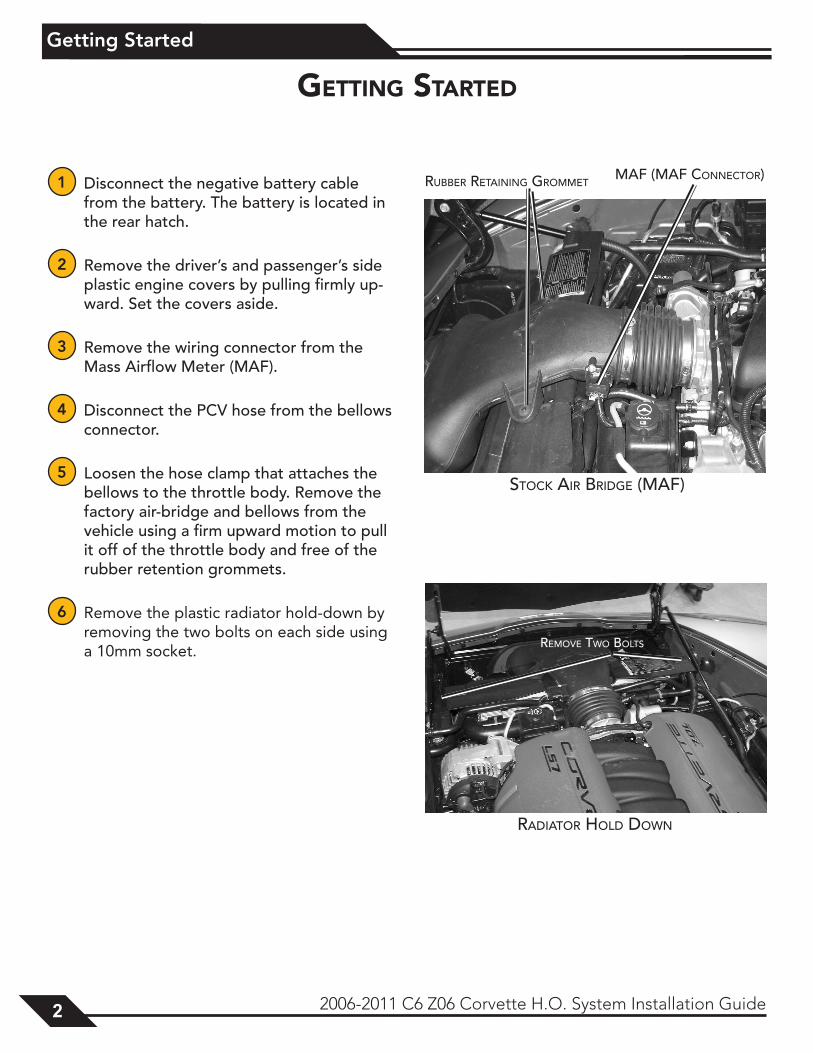
3 Remove the wiring connector from the Mass Airflow Meter (MAF).
4 Disconnect the PCV hose from the bellows connector.
5 Loosen the hose clamp that attaches the bellows to the throttle body. Remove the factory air-bridge and bellows from the vehicle using a firm upward motion to pull it off of the throttle body and free of the rubber retention grommets.
6 Remove the plastic radiator hold-down by removing the two bolts on each side using a 10mm socket.
GettInG started
Stock Air Bridge (MAF)
ruBBer retAining groMMetMAF (MAF connector)
rAdiAtor Hold down
reMove two BoltS
Getting Started
2006-2011 C6 Z06 Corvette H.O. System Installation Guide 3
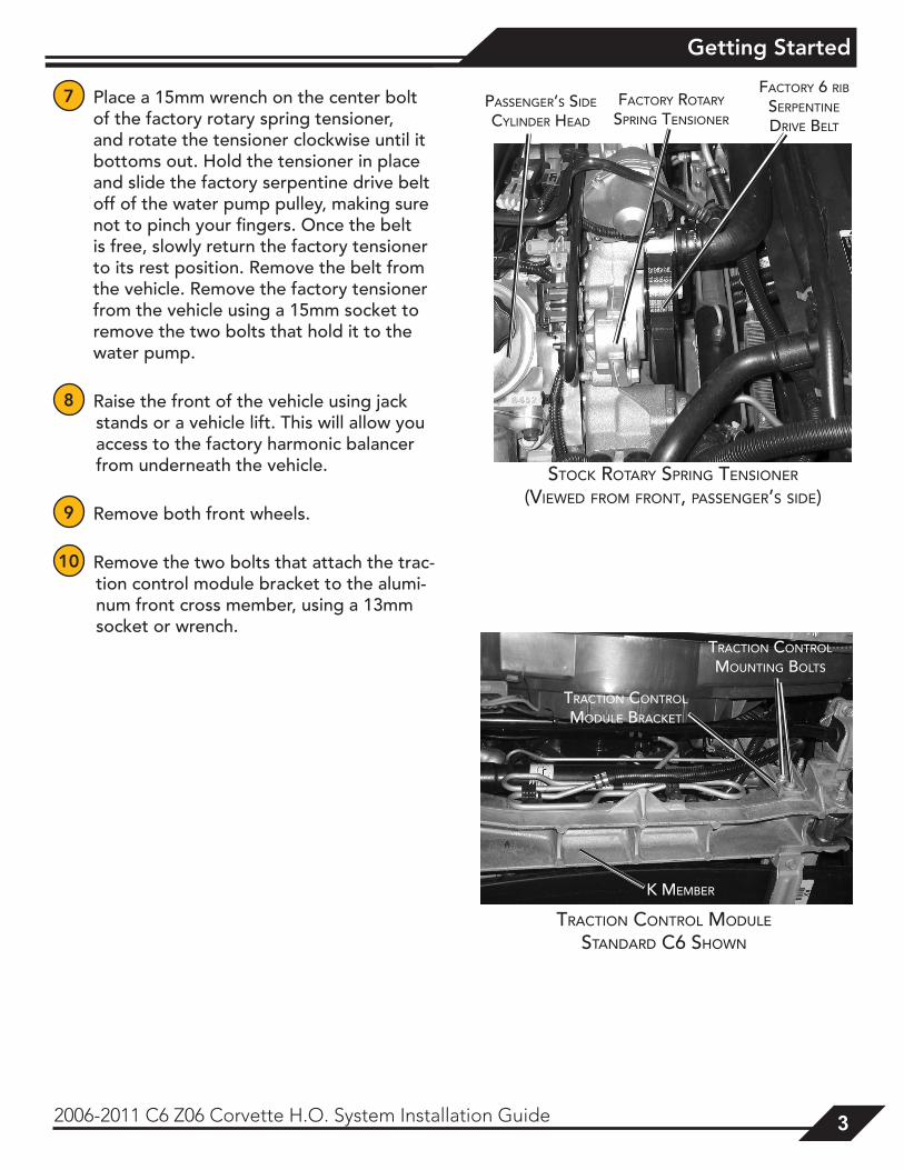
7 Place a 15mm wrench on the center bolt of the factory rotary spring tensioner, and rotate the tensioner clockwise until it bottoms out. Hold the tensioner in place and slide the factory serpentine drive belt off of the water pump pulley, making sure not to pinch your fingers. Once the belt is free, slowly return the factory tensioner to its rest position. Remove the belt from the vehicle. Remove the factory tensioner from the vehicle using a 15mm socket to remove the two bolts that hold it to the water pump.
8 Raise the front of the vehicle using jack stands or a vehicle lift. This will allow you access to the factory harmonic balancer from underneath the vehicle.
9 Remove both front wheels.
10 Remove the two bolts that attach the trac-tion control module bracket to the alumi-num front cross member, using a 13mm socket or wrench.
Stock rotAry Spring tenSioner
(viewed FroM Front, pASSenger’S Side)
pASSenger’S Side
cylinder HeAd
FActory rotAry
Spring tenSioner
FActory 6 riB
Serpentine drive Belt
trAction control Module
StAndArd c6 SHown
trAction control Mounting BoltS
trAction control Module BrAcket
k MeMBer
Harmonic Balancer
4 2006-2011 C6 Z06 Corvette H.O. System Installation Guide
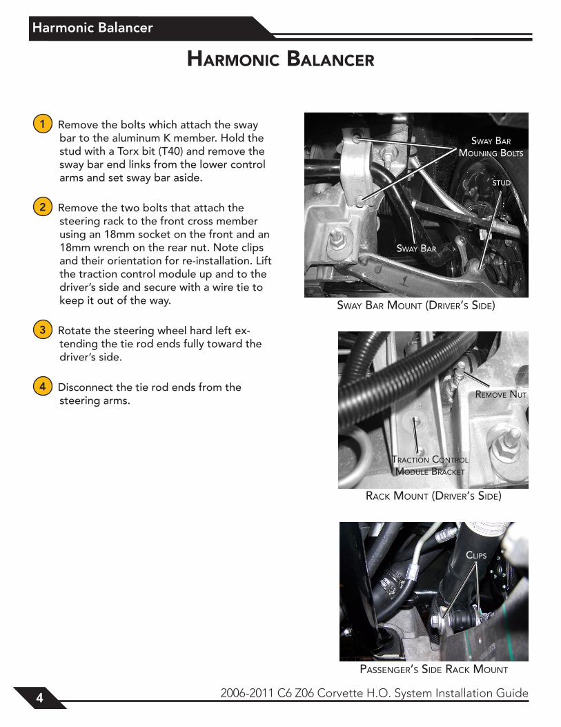
1 Remove the bolts which attach the sway bar to the aluminum K member. Hold the stud with a Torx bit (T40) and remove the sway bar end links from the lower control arms and set sway bar aside.
2 Remove the two bolts that attach the steering rack to the front cross member using an 18mm socket on the front and an 18mm wrench on the rear nut. Note clips and their orientation for re-installation. Lift the traction control module up and to the driver’s side and secure with a wire tie to keep it out of the way.
3 Rotate the steering wheel hard left ex-tending the tie rod ends fully toward the driver’s side.
4 Disconnect the tie rod ends from the steering arms.
SwAy BAr
SwAy BAr Mouning BoltS
Stud
SwAy BAr Mount (driver’S Side)
rAck Mount (driver’S Side)
reMove nut
trAction control Module BrAcket
HarmonIc balancer
pASSenger’S Side rAck Mount
clipS
Harmonic Balancer
2006-2011 C6 Z06 Corvette H.O. System Installation Guide 5
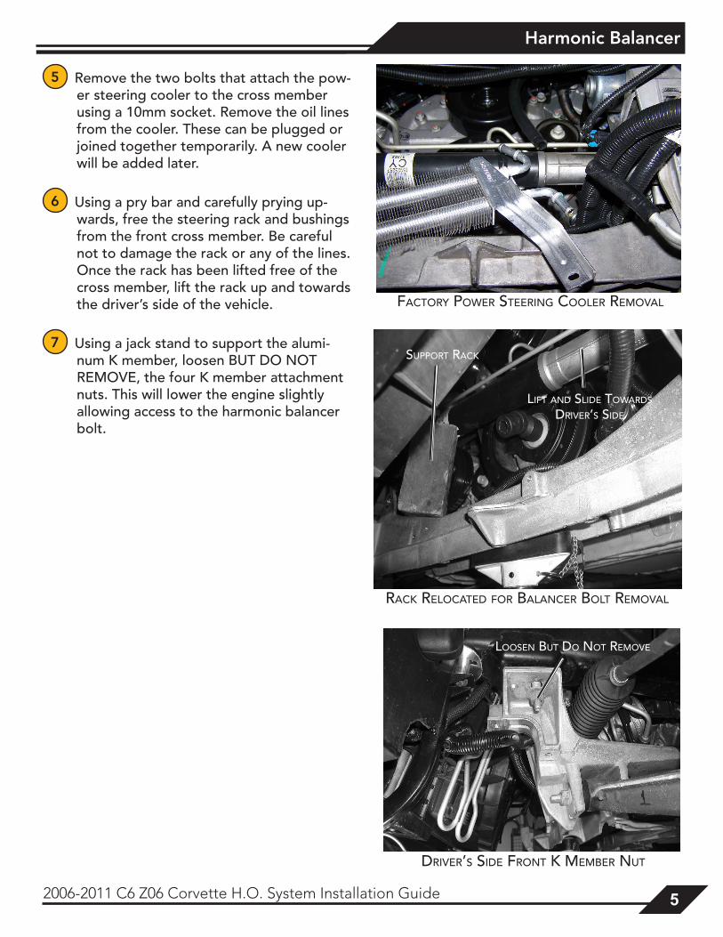
5 Remove the two bolts that attach the pow-er steering cooler to the cross member using a 10mm socket. Remove the oil lines from the cooler. These can be plugged or joined together temporarily. A new cooler will be added later.
6 Using a pry bar and carefully prying up-wards, free the steering rack and bushings from the front cross member. Be careful not to damage the rack or any of the lines. Once the rack has been lifted free of the cross member, lift the rack up and towards the driver’s side of the vehicle.
7 Using a jack stand to support the alumi-num K member, loosen BUT DO NOT REMOVE, the four K member attachment nuts. This will lower the engine slightly allowing access to the harmonic balancer bolt.
FActory power Steering cooler reMovAl
rAck relocAted For BAlAncer Bolt reMovAl
liFt And Slide towArdS driver’S Side
Support rAck
driver’S Side Front k MeMBer nut
looSen But do not reMove
Harmonic Balancer
6 2006-2011 C6 Z06 Corvette H.O. System Installation Guide
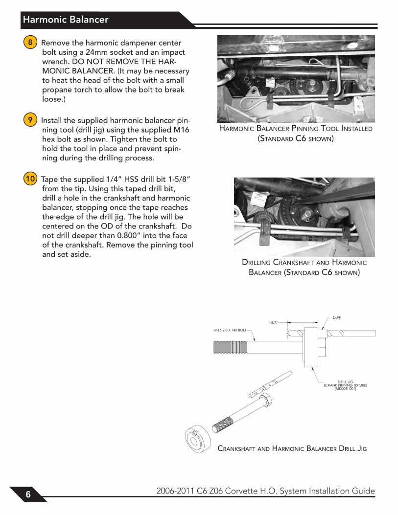
8 Remove the harmonic dampener center bolt using a 24mm socket and an impact wrench. DO NOT REMOVE THE HAR-MONIC BALANCER. (It may be necessary to heat the head of the bolt with a small propane torch to allow the bolt to break loose.)
9 Install the supplied harmonic balancer pin-ning tool (drill jig) using the supplied M16 hex bolt as shown. Tighten the bolt to hold the tool in place and prevent spin-ning during the drilling process.
10 Tape the supplied 1/4” HSS drill bit 1-5/8” from the tip. Using this taped drill bit, drill a hole in the crankshaft and harmonic balancer, stopping once the tape reaches the edge of the drill jig. The hole will be centered on the OD of the crankshaft. Do not drill deeper than 0.800” into the face of the crankshaft. Remove the pinning tool and set aside.
HArMonic BAlAncer pinning tool inStAlled
(StAndArd c6 SHown)
drilling crAnkSHAFt And HArMonic BAlAncer (StAndArd c6 SHown)
crAnkSHAFt And HArMonic BAlAncer drill Jig
Harmonic Balancer
2006-2011 C6 Z06 Corvette H.O. System Installation Guide 7
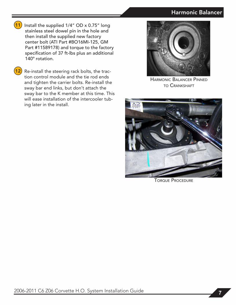
11 Install the supplied 1/4” OD x 0.75” long stainless steel dowel pin in the hole and then install the supplied new factory center bolt (ATI Part #BO16MI-125, GM Part #11589178) and torque to the factory specification of 37 ft-lbs plus an additional 140º rotation.
12 Re-install the steering rack bolts, the trac-tion control module and the tie rod ends and tighten the carrier bolts. Re-install the sway bar end links, but don’t attach the sway bar to the K member at this time. This will ease installation of the intercooler tub-ing later in the install.
HArMonic BAlAncer pinned to crAnkSHAFt
torque procedure
Front Fascia
8 2006-2011 C6 Z06 Corvette H.O. System Installation Guide
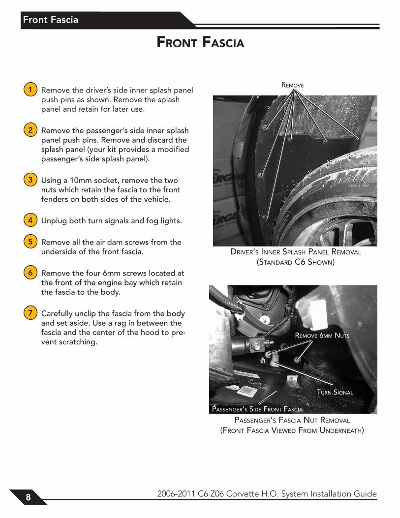
1 Remove the driver’s side inner splash panel push pins as shown. Remove the splash panel and retain for later use.
2 Remove the passenger’s side inner splash panel push pins. Remove and discard the splash panel (your kit provides a modified passenger’s side splash panel).
3 Using a 10mm socket, remove the two nuts which retain the fascia to the front fenders on both sides of the vehicle.
4 Unplug both turn signals and fog lights.
5 Remove all the air dam screws from the underside of the front fascia.
6 Remove the four 6mm screws located at the front of the engine bay which retain the fascia to the body.
7 Carefully unclip the fascia from the body and set aside. Use a rag in between the fascia and the center of the hood to pre-vent scratching.
reMove
driver’S inner SplASH pAnel reMovAl
(StAndArd c6 SHown)
front fascIa
pASSenger’S FASciA nut reMovAl
(Front FASciA viewed FroM underneAtH)
reMove 6MM nutS
turn SignAl
pASSenger’S Side Front FASciA
Radiator/Oil Cooler
2006-2011 C6 Z06 Corvette H.O. System Installation Guide 9
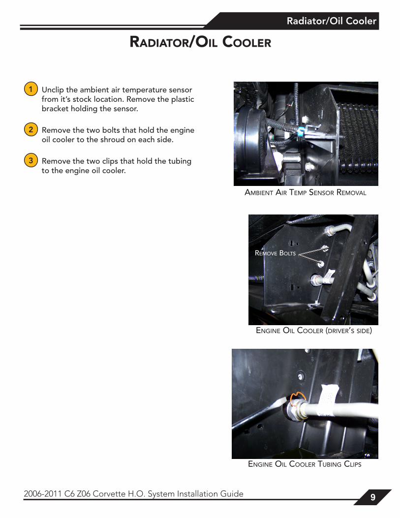
1 Unclip the ambient air temperature sensor from it’s stock location. Remove the plastic bracket holding the sensor.
2 Remove the two bolts that hold the engine oil cooler to the shroud on each side.
3 Remove the two clips that hold the tubing to the engine oil cooler.
AMBient Air teMp SenSor reMovAl
radIator/oIl cooler
engine oil cooler tuBing clipS
reMove BoltS
engine oil cooler (driver’S Side)
Radiator/Oil Cooler
10 2006-2011 C6 Z06 Corvette H.O. System Installation Guide
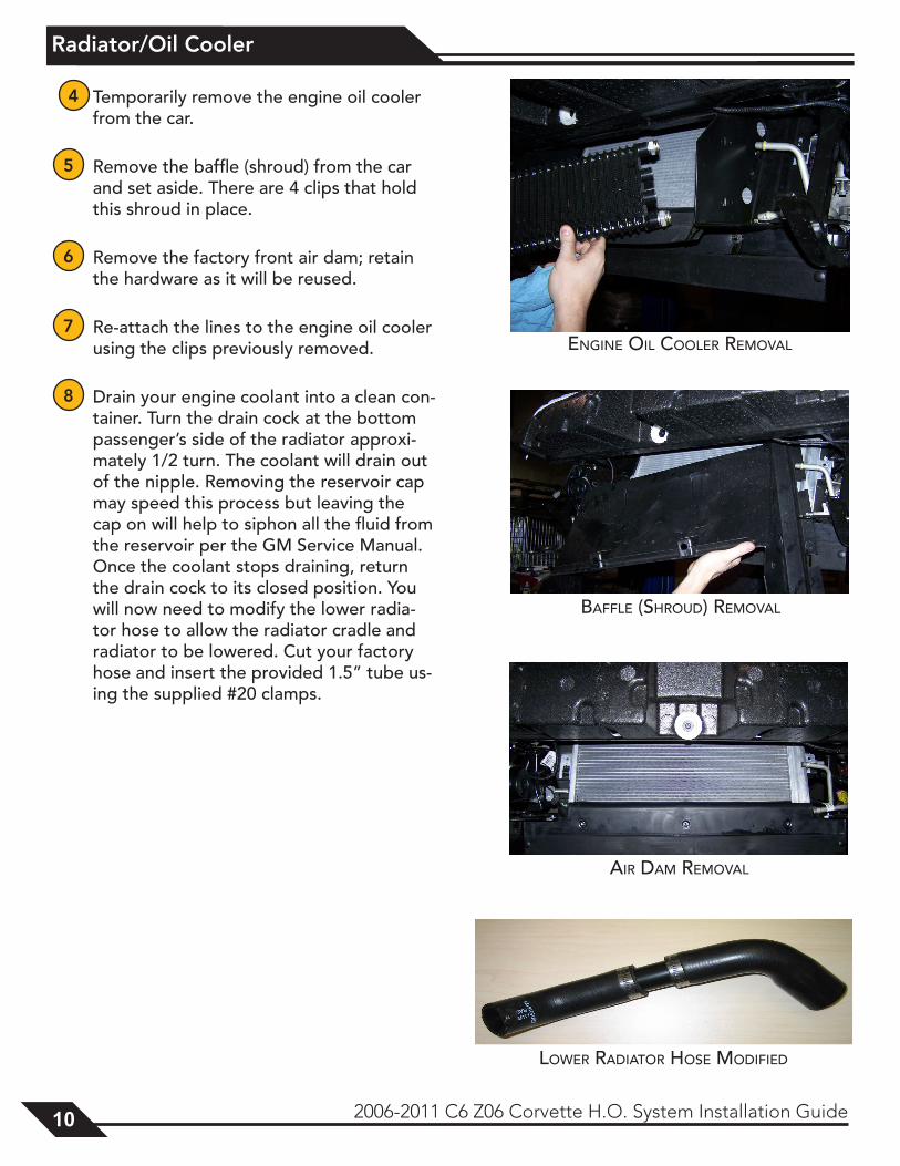
4 Temporarily remove the engine oil cooler from the car.
5 Remove the baffle (shroud) from the car and set aside. There are 4 clips that hold this shroud in place.
6 Remove the factory front air dam; retain the hardware as it will be reused.
7 Re-attach the lines to the engine oil cooler using the clips previously removed.
8 Drain your engine coolant into a clean con-tainer. Turn the drain cock at the bottom passenger’s side of the radiator approxi-mately 1/2 turn. The coolant will drain out of the nipple. Removing the reservoir cap may speed this process but leaving the cap on will help to siphon all the fluid from the reservoir per the GM Service Manual. Once the coolant stops draining, return the drain cock to its closed position. You will now need to modify the lower radia-tor hose to allow the radiator cradle and radiator to be lowered. Cut your factory hose and insert the provided 1.5” tube us-ing the supplied #20 clamps.
engine oil cooler reMovAl
lower rAdiAtor HoSe ModiFied
BAFFle (SHroud) reMovAl
Air dAM reMovAl
Radiator/Oil Cooler
2006-2011 C6 Z06 Corvette H.O. System Installation Guide 11
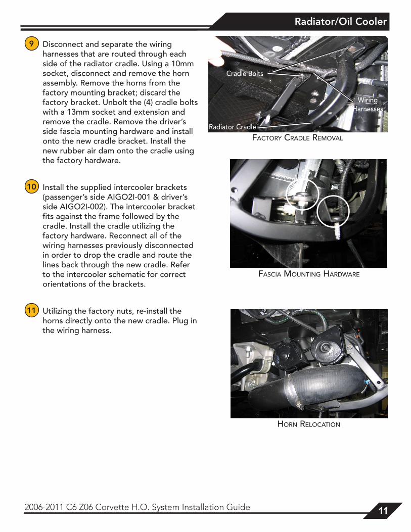
9 Disconnect and separate the wiring harnesses that are routed through each side of the radiator cradle. Using a 10mm socket, disconnect and remove the horn assembly. Remove the horns from the factory mounting bracket; discard the factory bracket. Unbolt the (4) cradle bolts with a 13mm socket and extension and remove the cradle. Remove the driver’s side fascia mounting hardware and install onto the new cradle bracket. Install the new rubber air dam onto the cradle using the factory hardware.
10 Install the supplied intercooler brackets (passenger’s side AIGO2I-001 & driver’s side AIGO2I-002). The intercooler bracket fits against the frame followed by the cradle. Install the cradle utilizing the factory hardware. Reconnect all of the wiring harnesses previously disconnected in order to drop the cradle and route the lines back through the new cradle. Refer to the intercooler schematic for correct orientations of the brackets.
11 Utilizing the factory nuts, re-install the horns directly onto the new cradle. Plug in the wiring harness.
FASciA Mounting HArdwAre
Horn relocAtion
Cradle Bolts
WiringHarnesses
Radiator CradleFActory crAdle reMovAl
Radiator/Oil Cooler
12 2006-2011 C6 Z06 Corvette H.O. System Installation Guide
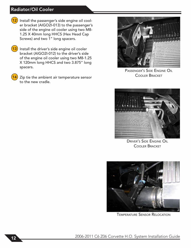
12 Install the passenger’s side engine oil cool-er bracket (AIGO2I-013) to the passenger’s side of the engine oil cooler using two M8-1.25 X 40mm long HHCS (Hex Head Cap Screws) and two 1” long spacers.
13 Install the driver’s side engine oil cooler bracket (AIGO2I-012) to the driver’s side of the engine oil cooler using two M8-1.25 X 120mm long HHCS and two 3.875” long spacers.
14 Zip tie the ambient air temperature sensor to the new cradle.
pASSenger’S Side engine oil cooler BrAcket
driver’S Side engine oil cooler BrAcket
teMperAture SenSor relocAtion
Coolant Hose Modification
2006-2011 C6 Z06 Corvette H.O. System Installation Guide 13
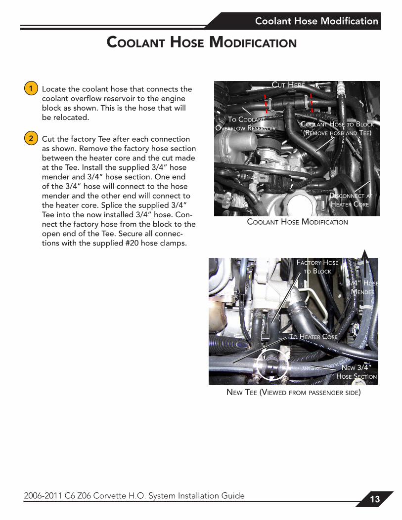
1 Locate the coolant hose that connects the coolant overflow reservoir to the engine block as shown. This is the hose that will be relocated.
2 Cut the factory Tee after each connection as shown. Remove the factory hose section between the heater core and the cut made at the Tee. Install the supplied 3/4” hose mender and 3/4” hose section. One end of the 3/4” hose will connect to the hose mender and the other end will connect to the heater core. Splice the supplied 3/4” Tee into the now installed 3/4” hose. Con-nect the factory hose from the block to the open end of the Tee. Secure all connec-tions with the supplied #20 hose clamps.
coolant Hose modIfIcatIon
coolAnt HoSe ModiFicAtion
diSconnect At HeAter core
to coolAnt overFlow reServoir
coolAnt HoSe to Block
(reMove HoSe And tee)
Coolant Hose to BloCk (Remove Hose and tee)
cut Here
new tee (viewed FroM pASSenger Side)
to HeAter core
new 3/4” HoSe Section
FActory HoSe to Block
3/4” HoSe Mender
ProCharger Installation
14 2006-2011 C6 Z06 Corvette H.O. System Installation Guide
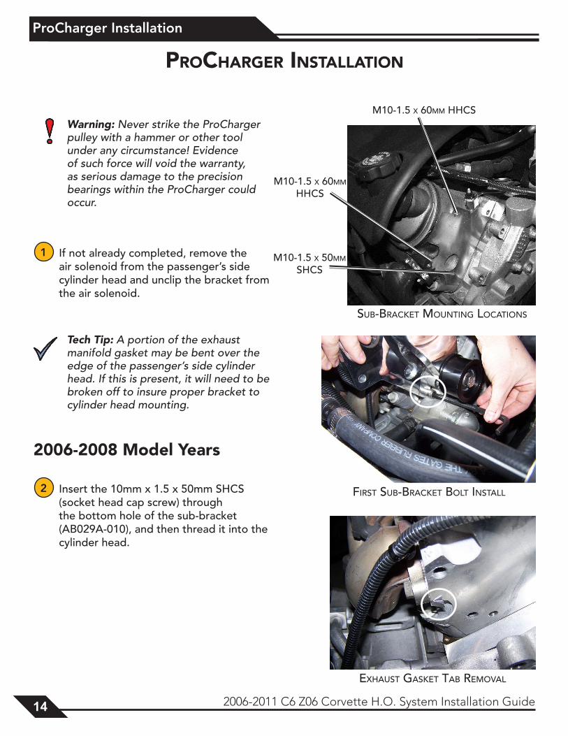
Warning: Never strike the ProCharger pulley with a hammer or other tool under any circumstance! Evidence of such force will void the warranty, as serious damage to the precision bearings within the ProCharger could occur.
1 If not already completed, remove the air solenoid from the passenger’s side cylinder head and unclip the bracket from the air solenoid.
Tech Tip: A portion of the exhaust manifold gasket may be bent over the edge of the passenger’s side cylinder head. If this is present, it will need to be broken off to insure proper bracket to cylinder head mounting.
2006-2008 Model Years
2 Insert the 10mm x 1.5 x 50mm SHCS (socket head cap screw) through the bottom hole of the sub-bracket (AB029A-010), and then thread it into the cylinder head.
ProcHarGer InstallatIon
SuB-BrAcket Mounting locAtionS
M10-1.5 x 60MM HHcS
M10-1.5 x 60MM HHcS
M10-1.5 x 50MM SHcS
FirSt SuB-BrAcket Bolt inStAll
exHAuSt gASket tAB reMovAl
ProCharger Installation
2006-2011 C6 Z06 Corvette H.O. System Installation Guide 15
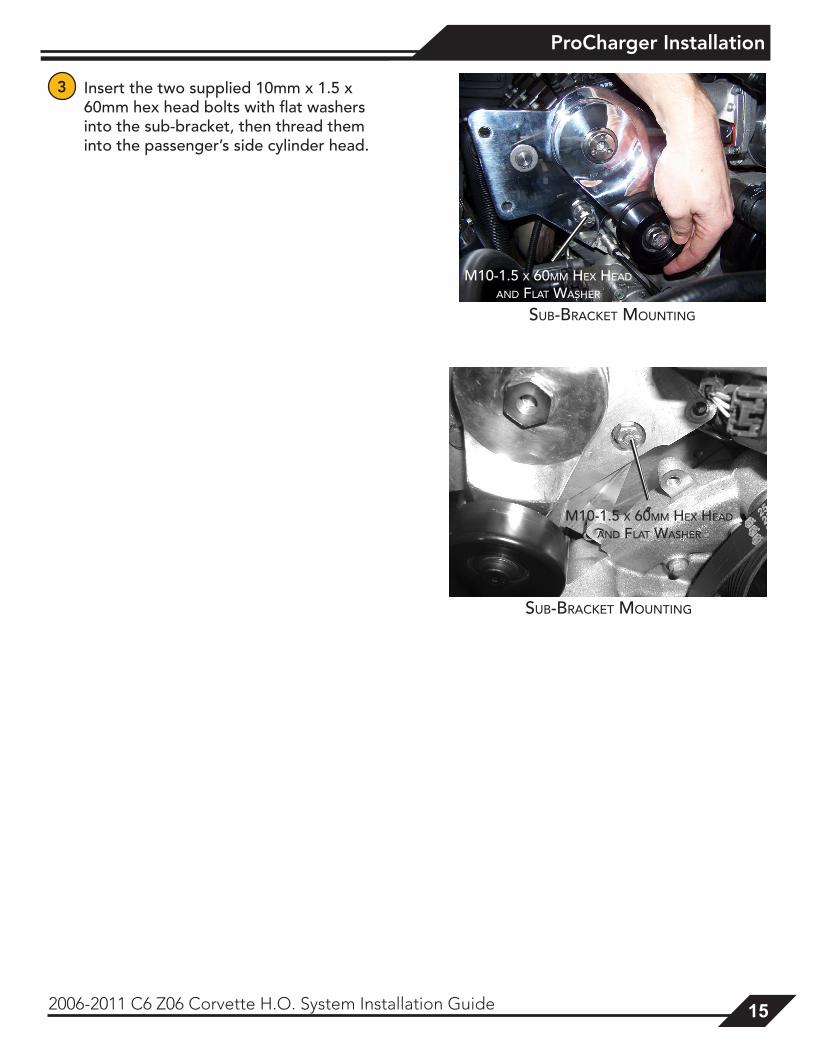
3 Insert the two supplied 10mm x 1.5 x 60mm hex head bolts with flat washers into the sub-bracket, then thread them into the passenger’s side cylinder head.
SuB-BrAcket Mounting
M10-1.5 x 60MM Hex HeAd
And FlAt wASHer
M10-1.5 x 60MM Hex HeAd
And FlAt wASHer
SuB-BrAcket Mounting
ProCharger Installation
16 2006-2011 C6 Z06 Corvette H.O. System Installation Guide
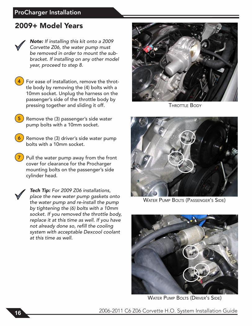
2009+ Model Years
Note: If installing this kit onto a 2009 Corvette Z06, the water pump must be removed in order to mount the sub-bracket. If installing on any other model year, proceed to step 8.
4 For ease of installation, remove the throt-tle body by removing the (4) bolts with a 10mm socket. Unplug the harness on the passenger’s side of the throttle body by pressing together and sliding it off.
5 Remove the (3) passenger’s side water pump bolts with a 10mm socket.
6 Remove the (3) driver’s side water pump bolts with a 10mm socket.
7 Pull the water pump away from the front cover for clearance for the Procharger mounting bolts on the passenger’s side cylinder head.
Tech Tip: For 2009 Z06 installations, place the new water pump gaskets onto the water pump and re-install the pump by tightening the (6) bolts with a 10mm socket. If you removed the throttle body, replace it at this time as well. If you have not already done so, refill the cooling system with acceptable Dexcool coolant at this time as well.
tHrottle Body
wAter puMp BoltS (pASSenger’S Side)
wAter puMp BoltS (driver’S Side)
ProCharger Installation
2006-2011 C6 Z06 Corvette H.O. System Installation Guide 17
All Model Years
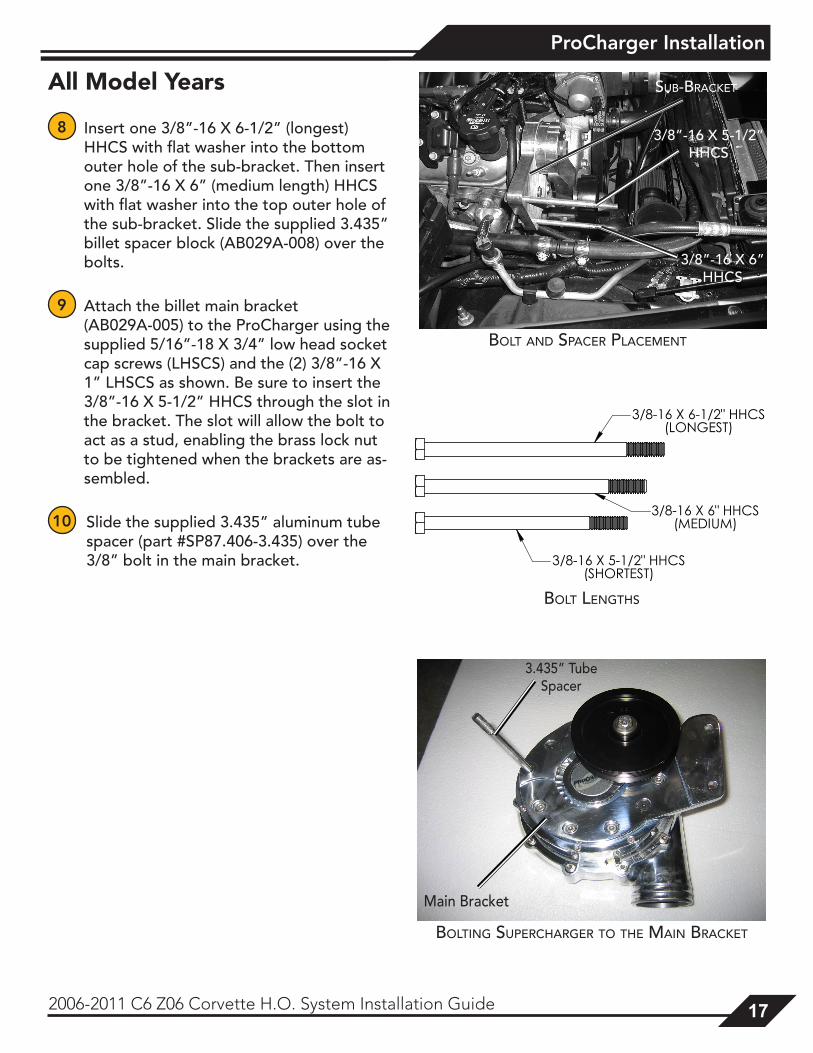
8 Insert one 3/8”-16 X 6-1/2” (longest) HHCS with flat washer into the bottom outer hole of the sub-bracket. Then insert one 3/8”-16 X 6” (medium length) HHCS with flat washer into the top outer hole of the sub-bracket. Slide the supplied 3.435” billet spacer block (AB029A-008) over the bolts.
9 Attach the billet main bracket (AB029A-005) to the ProCharger using the supplied 5/16”-18 X 3/4” low head socket cap screws (LHSCS) and the (2) 3/8”-16 X 1” LHSCS as shown. Be sure to insert the 3/8”-16 X 5-1/2” HHCS through the slot in the bracket. The slot will allow the bolt to act as a stud, enabling the brass lock nut to be tightened when the brackets are as-sembled.
10 Slide the supplied 3.435” aluminum tube spacer (part #SP87.406-3.435) over the 3/8” bolt in the main bracket.
SuB-BrAcket
3/8”-16 x 6” HHcS
3/8”-16 x 5-1/2” HHcS
Bolt And SpAcer plAceMent
Bolt lengtHS
Bolting SupercHArger to tHe MAin BrAcket
Main Bracket
3.435” Tube Spacer
ProCharger Installation
18 2006-2011 C6 Z06 Corvette H.O. System Installation Guide
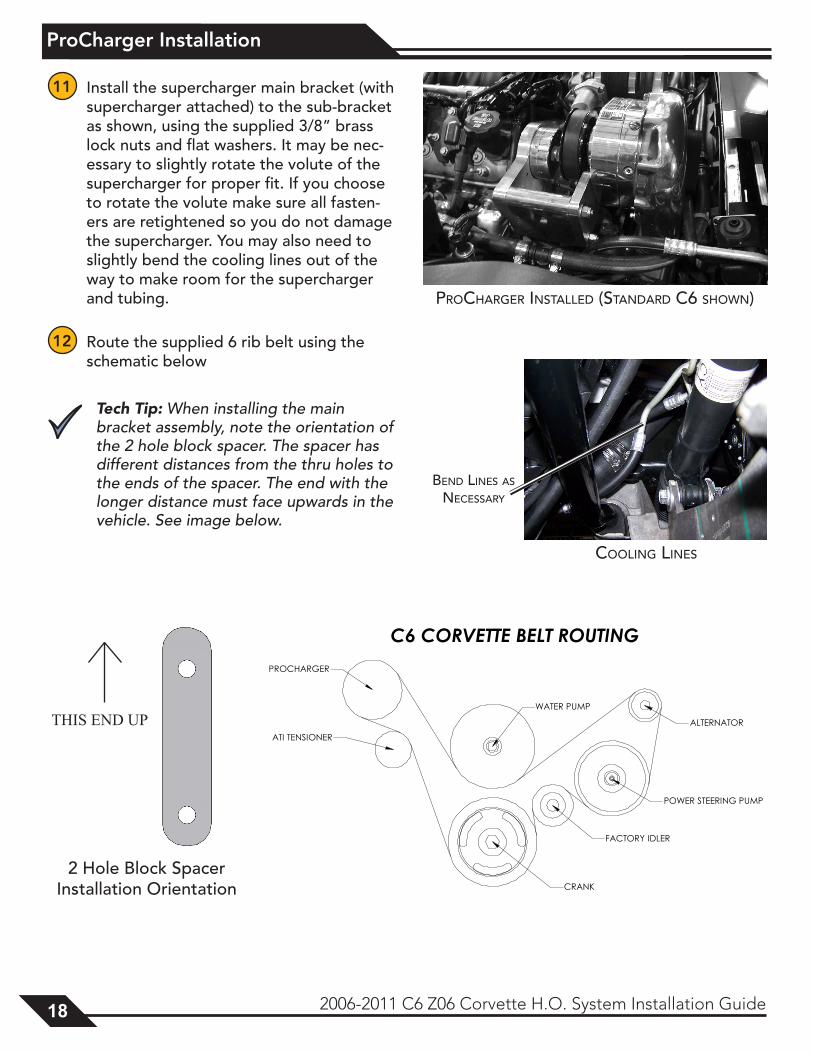
11 Install the supercharger main bracket (with supercharger attached) to the sub-bracket as shown, using the supplied 3/8” brass lock nuts and flat washers. It may be nec-essary to slightly rotate the volute of the supercharger for proper fit. If you choose to rotate the volute make sure all fasten-ers are retightened so you do not damage the supercharger. You may also need to slightly bend the cooling lines out of the way to make room for the supercharger and tubing.
12 Route the supplied 6 rib belt using the schematic below
Tech Tip: When installing the main bracket assembly, note the orientation of the 2 hole block spacer. The spacer has different distances from the thru holes to the ends of the spacer. The end with the longer distance must face upwards in the vehicle. See image below.
procHArger inStAlled (StAndArd c6 SHown)
cooling lineS
Bend lineS AS neceSSAry
2 Hole Block Spacer Installation Orientation
THIS END UP
ProCharger Installation
2006-2011 C6 Z06 Corvette H.O. System Installation Guide 19
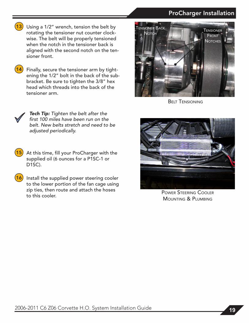
13 Using a 1/2” wrench, tension the belt by rotating the tensioner nut counter clock- wise. The belt will be properly tensioned when the notch in the tensioner back is aligned with the second notch on the ten-sioner front.
14 Finally, secure the tensioner arm by tight-ening the 1/2” bolt in the back of the sub-bracket. Be sure to tighten the 3/8” hex head which threads into the back of the tensioner arm.
Tech Tip: Tighten the belt after the first 100 miles have been run on the belt. New belts stretch and need to be adjusted periodically.
15 At this time, fill your ProCharger with the supplied oil (6 ounces for a P1SC-1 or D1SC).
16 Install the supplied power steering cooler to the lower portion of the fan cage using zip ties, then route and attach the hoses to this cooler.
power Steering cooler
Mounting & pluMBing
Belt tenSioning
tenSioner BAck notcH
tenSioner Front
notcHeS
Intercooler and Tubing Installation
20 2006-2011 C6 Z06 Corvette H.O. System Installation Guide
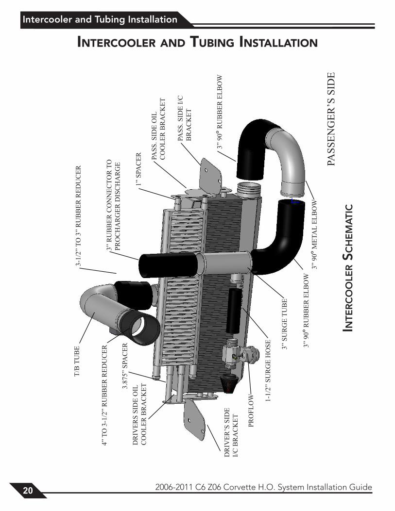
Intercooler and tubInG InstallatIon
T/B
TU
BE
3-1/
2” T
O 3
” R
UB
BER
RED
UC
ER
PASS
ENG
ER’S
SID
E
4” T
O 3
-1/2
” R
UB
BER
RED
UC
ER
1” S
PAC
ER PASS
. SID
E O
IL
CO
OLE
R B
RA
CK
ET
PASS
. SID
E I/C
B
RA
CK
ET
3” R
UB
BER
CO
NN
ECTO
R T
OPR
OC
HA
RG
ER D
ISC
HA
RG
E
DR
IVER
S SI
DE
OIL
C
OO
LER
BR
AC
KET
DR
IVER
’S S
IDE
I/C B
RA
CK
ET
3.87
5” S
PAC
ER
3” 9
0º R
UB
BER
ELB
OW
3” 9
0º R
UB
BER
ELB
OW
3” S
UR
GE
TUB
E
1-1/
2” S
UR
GE
HO
SE
PRO
FLO
W
3” 9
0º M
ETA
L EL
BO
W
Inte
rc
oo
ler S
ch
em
atI
c
Intercooler and Tubing Installation
2006-2011 C6 Z06 Corvette H.O. System Installation Guide 21
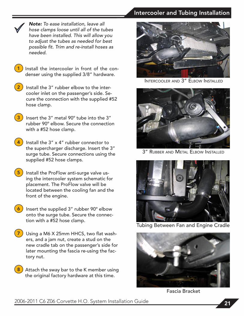
Note: To ease installation, leave all hose clamps loose until all of the tubes have been installed. This will allow you to adjust the tubes as needed for best possible fit. Trim and re-install hoses as needed.
1 Install the intercooler in front of the con-denser using the supplied 3/8” hardware.
2 Install the 3” rubber elbow to the inter-cooler inlet on the passenger’s side. Se-cure the connection with the supplied #52 hose clamp.
3 Insert the 3” metal 90º tube into the 3” rubber 90º elbow. Secure the connection with a #52 hose clamp.
4 Install the 3” x 4” rubber connector to the supercharger discharge. Insert the 3” surge tube. Secure connections using the supplied #52 hose clamps.
5 Install the ProFlow anti-surge valve us-ing the intercooler system schematic for placement. The ProFlow valve will be located between the cooling fan and the front of the engine.
6 Insert the supplied 3” rubber 90º elbow onto the surge tube. Secure the connec-tion with a #52 hose clamp.
7 Using a M6 X 25mm HHCS, two flat wash-ers, and a jam nut, create a stud on the new cradle tab on the passenger’s side for later mounting the fascia re-using the fac-tory nut.
8 Attach the sway bar to the K member using the original factory hardware at this time.
intercooler And 3” elBow inStAlled
3” ruBBer And MetAl elBow inStAlled
Fascia Bracket
Tubing Between Fan and Engine Cradle
Intercooler and Tubing Installation
22 2006-2011 C6 Z06 Corvette H.O. System Installation Guide
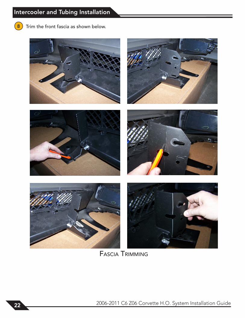
8 Trim the front fascia as shown below.
FASciA triMMing
Intercooler and Tubing Installation
2006-2011 C6 Z06 Corvette H.O. System Installation Guide 23
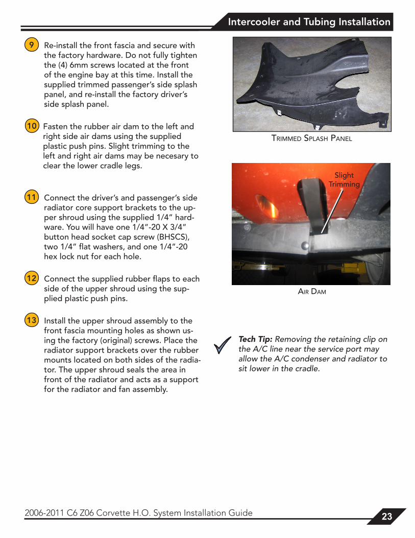
9 Re-install the front fascia and secure with the factory hardware. Do not fully tighten the (4) 6mm screws located at the front of the engine bay at this time. Install the supplied trimmed passenger’s side splash panel, and re-install the factory driver’s side splash panel.
10 Fasten the rubber air dam to the left and right side air dams using the supplied plastic push pins. Slight trimming to the left and right air dams may be necesary to clear the lower cradle legs.
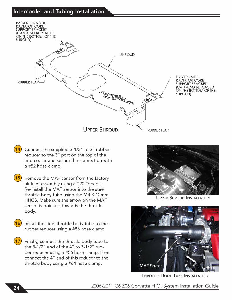
11 Connect the driver’s and passenger’s side radiator core support brackets to the up-per shroud using the supplied 1/4” hard-ware. You will have one 1/4”-20 X 3/4” button head socket cap screw (BHSCS), two 1/4” flat washers, and one 1/4”-20 hex lock nut for each hole.
12 Connect the supplied rubber flaps to each side of the upper shroud using the sup-plied plastic push pins.
13 Install the upper shroud assembly to the front fascia mounting holes as shown us-ing the factory (original) screws. Place the radiator support brackets over the rubber mounts located on both sides of the radia-tor. The upper shroud seals the area in front of the radiator and acts as a support for the radiator and fan assembly.
Tech Tip: Removing the retaining clip on the A/C line near the service port may allow the A/C condenser and radiator to sit lower in the cradle.
triMMed SplASH pAnel
Slight Trimming
Air dAM
Intercooler and Tubing Installation
24 2006-2011 C6 Z06 Corvette H.O. System Installation Guide
14 Connect the supplied 3-1/2” to 3” rubber reducer to the 3” port on the top of the intercooler and secure the connection with a #52 hose clamp.
15 Remove the MAF sensor from the factory air inlet assembly using a T20 Torx bit. Re-install the MAF sensor into the steel throttle body tube using the M4 X 12mm HHCS. Make sure the arrow on the MAF sensor is pointing towards the throttle body.
16 Install the steel throttle body tube to the rubber reducer using a #56 hose clamp.
17 Finally, connect the throttle body tube to the 3-1/2” end of the 4” to 3-1/2” rub-ber reducer using a #56 hose clamp, then connect the 4” end of this reducer to the throttle body using a #64 hose clamp.
upper SHroud
upper SHroud inStAllAtion
MAF SenSor
tHrottle Body tuBe inStAllAtion
Fuel Injector Replacement
2006-2011 C6 Z06 Corvette H.O. System Installation Guide 25
Note: This section only applies to full systems, which include upgraded fuel injectors. If you do not have a full system, upgraded fuel injectors will be required before starting the vehicle.
1 Remove the gas cap to relieve vapor pressure in the fuel tank, and connect the negative battery cable.
Tech Tip: If the vehicle cannot be started to depressurize the fuel system, relieving the pressure by pressing the pin on the schrader valve is acceptable. Place a shop rag under the valve to collect leaking fuel.
2 Remove the fuel pump fuse from the fuse block in front of the battery. Crank the engine over for 5 seconds (the engine will not start) to bleed fuel pressure from the fuel lines and fuel rail assembly.
3 Remove the keys from the ignition. Replace the fuel pump fuse. Disconnect the negative battery cable.
Warning: The fuel system should be de-pressurized, but some fuel may leak out when the lines are disconnected. Take the necessary precautions to avoid injury or fire.
4 Using the supplied fuel fitting quick-disconnect tool, remove the supply line from the fuel rail (place a shop towel underneath the fitting on the driver’s side to minimize fuel leakage).
5 Disconnect the fuel injector electrical connectors one at a time, labeling them by their corresponding injector location.
6 Disconnect the fuel rail wiring harness from the fuel rail. Remove the fuel rail attaching bolts.
7 Remove the fuel rail assembly as one piece with the injectors still attached and place on a clean work surface, making sure to support the assembly to avoid damaging any of the components. Have a shop rag accessible for leaking fuel.
8 Spread the injector retainer clips to release each injector from the fuel rail. Remove the old injectors and set aside. You are now ready to install the new injectors.
9 Remove the protective plastic caps from each end of the new injectors, being careful not to damage the o-ring seals. Lubricate each new injector o-ring seal with several drops of clean engine oil.
Warning: Never re-use fuel injector o-ring seals, as they lose elasticity over time and could cause a fuel leak and/or potential fire.
fuel Injector rePlacement
Fuel Injector Replacement
26 2006-2011 C6 Z06 Corvette H.O. System Installation Guide
10 Install the retainer clips that were removed in step 8 onto the new injectors. Push each injector into the fuel rail injector socket with the electrical connector facing outward. The retainer clip should lock onto a flange on the fuel rail.
11 Install the fuel rail assembly onto the intake manifold, making sure that the injectors are rotated to line up with their corresponding electrical connectors. Using Loctite 272™ (high temperature thread locker) or equivalent, install the fuel rail bolts and the supplied 1⁄2” spacers and torque to 90 in-lbs.
12 Connect each injector to the factory harness.
13 Replace the gas cap and negative battery cable. Re-install the fuel supply hose by pressing the fitting onto the fuel rail fitting until a snap is heard.
14 Check the new injectors for leaks by turning the ignition to the “on” position for 2 seconds, but do not start the engine! Turn the ignition off for 10 seconds. Turn the ignition to the “on” position. Check for fuel leaks at both ends of each injector and at the fuel supply hose fittings.
15 Proceed to the next section if no leaks are detected, otherwise, review the installation and remedy any problems.
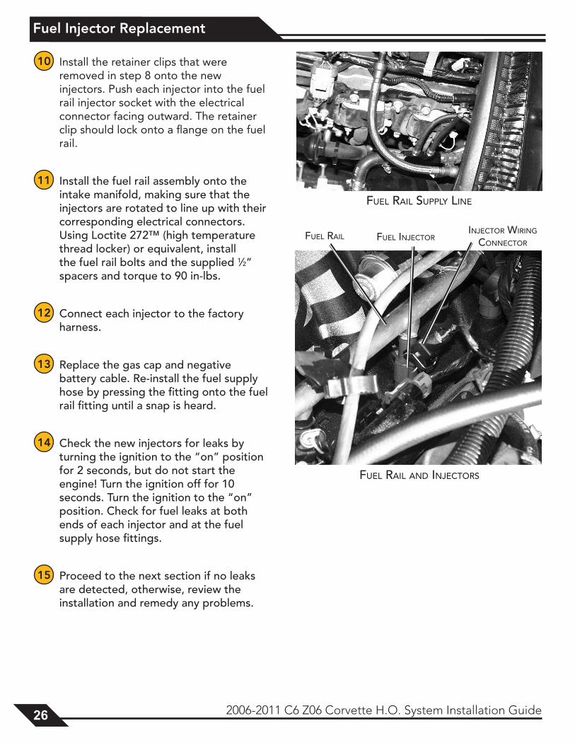
Fuel rAil Supply line
Fuel rAil
Fuel rAil And inJectorS
Fuel inJectorinJector wiring
connector
Vacuum Manifold Installation
2006-2011 C6 Z06 Corvette H.O. System Installation Guide 27
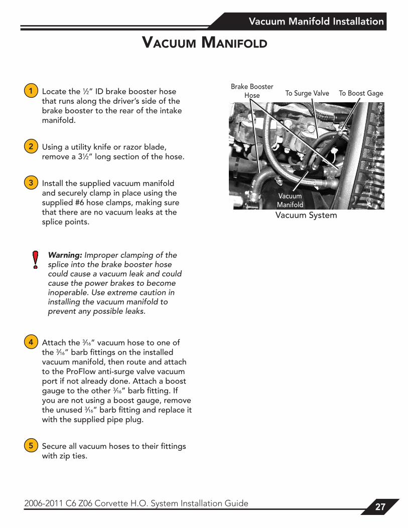
1 Locate the 1⁄2” ID brake booster hose that runs along the driver’s side of the brake booster to the rear of the intake manifold.
2 Using a utility knife or razor blade, remove a 31⁄2” long section of the hose.
3 Install the supplied vacuum manifold and securely clamp in place using the supplied #6 hose clamps, making sure that there are no vacuum leaks at the splice points.
Warning: Improper clamping of the splice into the brake booster hose could cause a vacuum leak and could cause the power brakes to become inoperable. Use extreme caution in installing the vacuum manifold to prevent any possible leaks.
4 Attach the 3⁄16” vacuum hose to one of the 3⁄16” barb fittings on the installed vacuum manifold, then route and attach to the ProFlow anti-surge valve vacuum port if not already done. Attach a boost gauge to the other 3⁄16” barb fitting. If you are not using a boost gauge, remove the unused 3⁄16” barb fitting and replace it with the supplied pipe plug.
5 Secure all vacuum hoses to their fittings with zip ties.
Vacuum manIfold
Vacuum System
Vacuum Manifold
Brake Booster Hose To Surge Valve To Boost Gage
Final Assembly
28 2006-2011 C6 Z06 Corvette H.O. System Installation Guide
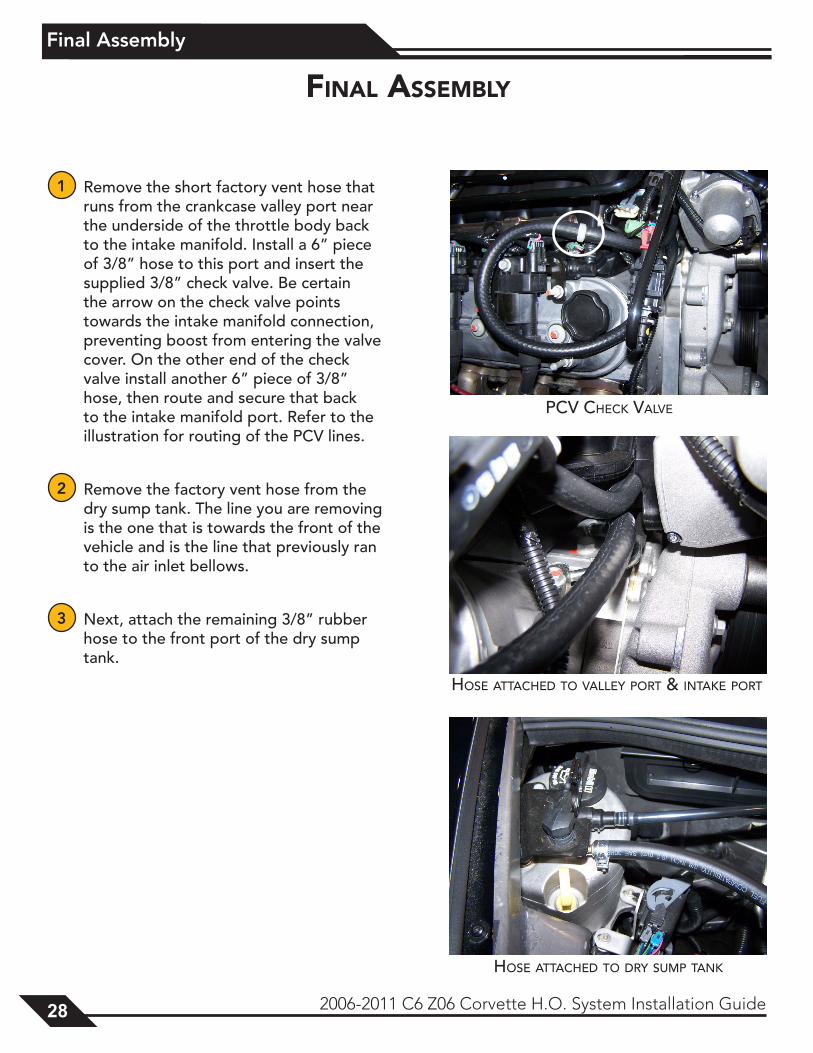
1 Remove the short factory vent hose that runs from the crankcase valley port near the underside of the throttle body back to the intake manifold. Install a 6” piece of 3/8” hose to this port and insert the supplied 3/8” check valve. Be certain the arrow on the check valve points towards the intake manifold connection, preventing boost from entering the valve cover. On the other end of the check valve install another 6” piece of 3/8” hose, then route and secure that back to the intake manifold port. Refer to the illustration for routing of the PCV lines.
2 Remove the factory vent hose from the dry sump tank. The line you are removing is the one that is towards the front of the vehicle and is the line that previously ran to the air inlet bellows.
3 Next, attach the remaining 3/8” rubber hose to the front port of the dry sump tank.
HoSe AttAcHed to vAlley port & intAke port
HoSe AttAcHed to dry SuMp tAnk
pcv cHeck vAlve
fInal assembly
Final Assembly
2006-2011 C6 Z06 Corvette H.O. System Installation Guide 29
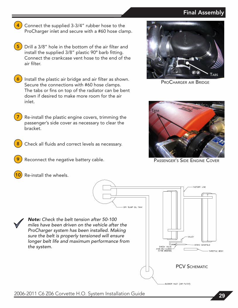
4 Connect the supplied 3-3/4” rubber hose to the ProCharger inlet and secure with a #60 hose clamp.
5 Drill a 3/8” hole in the bottom of the air filter and install the supplied 3/8” plastic 90º barb fitting. Connect the crankcase vent hose to the end of the air filter.
6 Install the plastic air bridge and air filter as shown. Secure the connections with #60 hose clamps. The tabs or fins on top of the radiator can be bent down if desired to make more room for the air inlet.
7 Re-install the plastic engine covers, trimming the passenger’s side cover as necessary to clear the bracket.
8 Check all fluids and correct levels as necessary.
9 Reconnect the negative battery cable.
10 Re-install the wheels.
Note: Check the belt tension after 50-100 miles have been driven on the vehicle after the ProCharger system has been installed. Making sure the belt is properly tensioned will ensure longer belt life and maximum performance from the system.
pcv ScHeMAtic
procHArger Air Bridge
tABS
pASSenger’S Side engine cover
triM
Tuning
30 2006-2011 C6 Z06 Corvette H.O. System Installation Guide
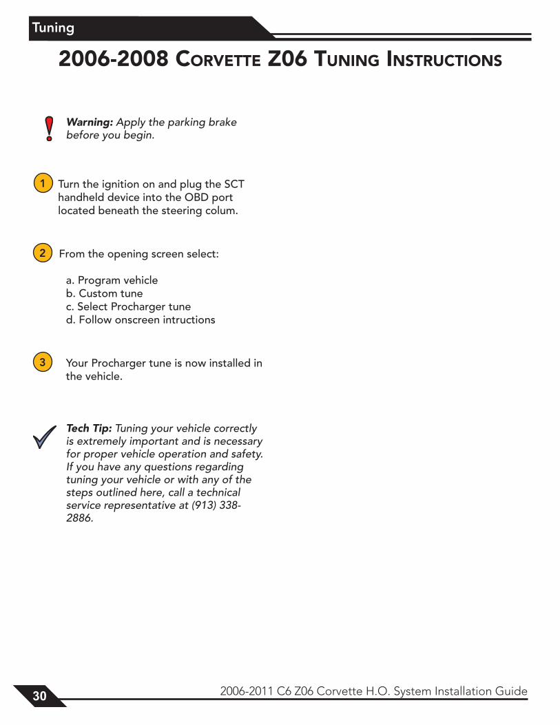
Warning: Apply the parking brake before you begin.
1 Turn the ignition on and plug the SCT handheld device into the OBD port located beneath the steering colum.
2 From the opening screen select:
a. Program vehicle b. Custom tune c. Select Procharger tune d. Follow onscreen intructions
3 Your Procharger tune is now installed in the vehicle.
Tech Tip: Tuning your vehicle correctly is extremely important and is necessary for proper vehicle operation and safety. If you have any questions regarding tuning your vehicle or with any of the steps outlined here, call a technical service representative at (913) 338-2886.
2006-2008 corVette Z06 tunInG InstructIons
Tuning
2006-2011 C6 Z06 Corvette H.O. System Installation Guide 31
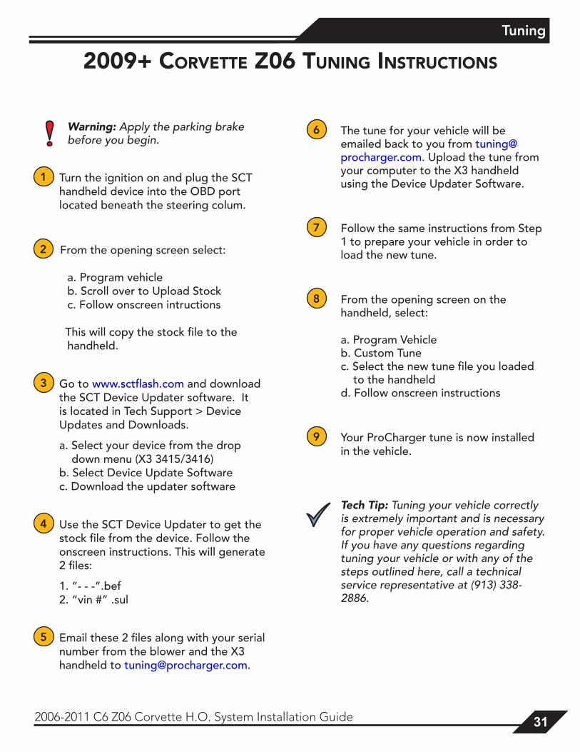
Warning: Apply the parking brake before you begin.
1 Turn the ignition on and plug the SCT handheld device into the OBD port located beneath the steering colum.
2 From the opening screen select:
a. Program vehicle b. Scroll over to Upload Stock c. Follow onscreen intructions
This will copy the stock file to the handheld.
3 Go to www.sctflash.com and download the SCT Device Updater software. It is located in Tech Support > Device Updates and Downloads.
a. Select your device from the drop down menu (X3 3415/3416) b. Select Device Update Software c. Download the updater software
4 Use the SCT Device Updater to get the stock file from the device. Follow the onscreen instructions. This will generate 2 files:
1. “- - -”.bef 2. “vin #” .sul
5 Email these 2 files along with your serial number from the blower and the X3 handheld to [email protected].
6 The tune for your vehicle will be emailed back to you from [email protected]. Upload the tune from your computer to the X3 handheld using the Device Updater Software.
7 Follow the same instructions from Step 1 to prepare your vehicle in order to load the new tune.
8 From the opening screen on the handheld, select:
a. Program Vehicle b. Custom Tune c. Select the new tune file you loaded to the handheld d. Follow onscreen instructions
9 Your ProCharger tune is now installed in the vehicle.
Tech Tip: Tuning your vehicle correctly is extremely important and is necessary for proper vehicle operation and safety. If you have any questions regarding tuning your vehicle or with any of the steps outlined here, call a technical service representative at (913) 338-2886.
2009+ corVette Z06 tunInG InstructIons
Supplemental Notes
32 2006-2011 C6 Z06 Corvette H.O. System Installation Guide
Tuning:Proper air-fuel ratio is the main tuning issue of your system. The ProCharger is nothing more than an efficient air pump used to substantially increase the volumetric efficiency of your engine. Intercooling is utilized to remove the heat caused by compressing the air. Maintaining the proper air-fuel ratio is extremely important. In order to extract as much power as possible from this increased air flow, the proper amount of fuel must be added. A lean condition will cause the car to detonate (which, under higher boost conditions, can cause engine damage), run hot or break up.
To get the most out of your system it will prove beneficial to utilize an air-fuel ratio meter. Wide band units are most ideal when tuning an engine for maximum performance. Usage of a wide band sensor will provide data that will allow you to achieve optimum performance throughout your engine’s operating range. It is highly recommended that you monitor the air-fuel ratio during operation, and you should see proper fuel ratios throughout the RPM range.
coolInG:Engine operating temperature for a LS7 Cor-vette has been designed by the factory to be between 204ºF and 235 ºF. The factory has designed the cooling fan to come on at 204ºF (10% duty cycle) and reaches 90% duty cycle (high speed) when the coolant temperature reaches 235ºF to maintain this temperature range. The factory thermostat is a 187ºF unit and will remain closed below that temperature. In other words, below 187ºF no coolant will circulate between the radiator and the water pump. The vehicle PCM will illuminate the COOLANT OVER TEMP indicator if the engine temperature exceeds 256ºF.
off-road notes:If using a stock ignition system the plug gap may be reduced to approximately 0.035” to avoid “blowing out” the flame or spark. The use of non-platinum plugs one heat range cooler than stock is also helpful.
suPPlemental notes
Installation Review & Safety Check
2006-2011 C6 Z06 Corvette H.O. System Installation Guide 33
Carefully review the entire installation. Examine all lines routed near moving parts and exhaust components to ensure that they are protected from chafing or abrasion, secure and free of twists and kinks. All wires and hoses should be firmly secured with clamps or wire ties. Also, ensure that the air filter is installed.
1 Check and correct all fluid levels (oil, power steering, and coolant). Your vehicle should be filled with 91 or higher octane fuel before any hard driving.
2 Start engine and idle for a few minutes. Inspect connections for air or fluid leaks.
3 Shut off engine and check for fluid leakage, signs of rubbing parts, and other potential problems.
4 Your vehicle should display a significant, detonation free increase in performance when you step into the throttle, yet maintain its previous driveability during daily driving. If this is not so, review your installation, then contact your dealer or ATI for assistance.
5 Be sure you have purchased and properly installed a fuel pressure gauge to monitor fuel delivery while driving. An air/fuel ratio meter is also helpful for monitoring fuel delivery. Installation of a boost pressure gauge is also recommended.
6 Please review the maintenance and warranty sections within this owner’s manual.
Note: Larger cities (especially in winter months) often use oxygenated or reformulated fuels to reduce pollution. Although these fuels have the same octane ratings as unaltered fuels, some people have experienced problems (detonation) with their use. If you experience similar problems, it is advised to use octane booster to avoid detonation.
InstallatIon reVIew & safety cHeck
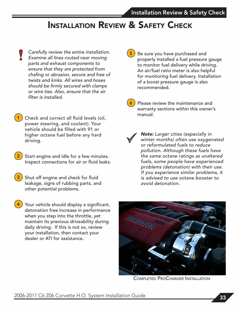
coMpleted procHArger inStAllAtion
Operation & Maintenance
34 2006-2011 C6 Z06 Corvette H.O. System Installation Guide
Cold StartingNever race your engine (and ProCharger) when your engine is cold. Allow the water temperature to climb into operating range for several minutes before driving above 2,500 rpm, to ensure adequate oil lubrication.
Fuel QualityFor best performance and reliability, always use premium grade fuel (91 octane or higher). Always listen for signs of detonation after refueling, and after replacement or modification of any fuel system components. Back off throttle should detonation occur. With a properly installed ProCharger intercooled supercharger system, detonation should not be an issue.
Ignition System MaintenanceIf your spark plugs are more than a year old or have more than 10,000 miles logged, you should consider changing them before driving your vehicle under load. Additionally, spark plug wires should be changed if visibly damaged or whenever resistance exceeds factory specifications.
Air Filter MaintenanceYour air filters should be cleaned periodically, potentially as often as every 10,000 miles or 6 months, even though a service interval of 50,000 - 100,000 miles is quoted by the manufacturer under normal driving conditions. A clogged air filter will result in decreased boost levels and vehicle performance. K&N air filter cleaner is recommended, and be sure to re-oil the cleaned filter before re-installing. Always operate your vehicle with an air filter; failure to do so may result in damage to your ProCharger and/or personal injury!
Belt ReplacementThe belt which turns your ProCharger will stretch after initial run-in, and should be re-tightened after approximately the first hundred miles. After possibly one more tightening of the belt with the tensioner, further stretching should not occur. Tighten the belt sufficiently to avoid slippage, but do not overtighten, as this could cause damage to the ProCharger’s precision bearings. When removing belts, ensure that they are re-installed to turn in the same direction as before. Should you reuse a thrown belt and find that it needs frequent re-tightening, the belt is damaged and should be replaced. Belts can be purchased from ATI or from your local parts store. Gates Micro-V belts are recommended; these belts are available at CarQuest®, NAPA® and other auto parts stores. Your nearest CarQuest store can be found by dialing 800-492-7278, the nearest NAPA store at 800-538-6272.
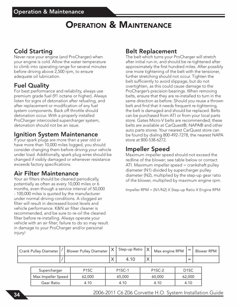
Impeller SpeedMaximum impeller speed should not exceed the redline of the blower; see table below or contact ATI. Maximum impeller speed = crankshaft pulley diameter (N1) divided by supercharger pulley diameter (N2), multiplied by the step-up gear ratio of the blower, multiplied by maximum engine rpm.
Impeller RPM = (N1/N2) X Step-up Ratio X Engine RPM
Crank Pulley Diameter / Blower Pulley Diameter X Step-up Ratio X Max engine RPM = Blower RPM
/ X 4.10 X =
Supercharger P1SC P1SC-1 P1SC-2 D1SC
Max Impeller Speed 62,000 65,000 60,000 62,000
Gear Ratio 4.10 4.10 4.10 4.10
oPeratIon & maIntenance
Operation & Maintenance
2006-2011 C6 Z06 Corvette H.O. System Installation Guide 35
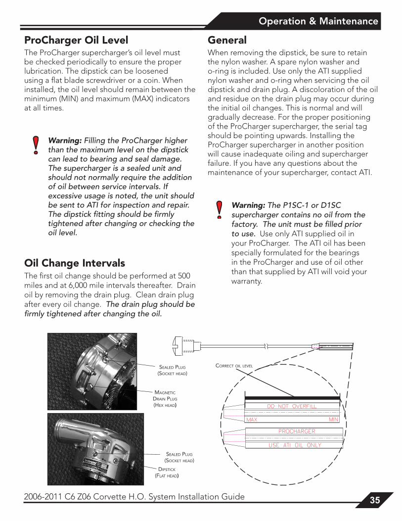
Sealed Plug
(Socket head)
diPStick
(Flat head)
Sealed Plug
(Socket head)
Magnetic drain Plug
(hex head)
correct oil level
ProCharger Oil LevelThe ProCharger supercharger’s oil level must be checked periodically to ensure the proper lubrication. The dipstick can be loosened using a flat blade screwdriver or a coin. When installed, the oil level should remain between the minimum (MIN) and maximum (MAX) indicators at all times.
Warning: Filling the ProCharger higher than the maximum level on the dipstick can lead to bearing and seal damage. The supercharger is a sealed unit and should not normally require the addition of oil between service intervals. If excessive usage is noted, the unit should be sent to ATI for inspection and repair. The dipstick fitting should be firmly tightened after changing or checking the oil level.
Oil Change IntervalsThe first oil change should be performed at 500 miles and at 6,000 mile intervals thereafter. Drain oil by removing the drain plug. Clean drain plug after every oil change. The drain plug should be firmly tightened after changing the oil.
GeneralWhen removing the dipstick, be sure to retain the nylon washer. A spare nylon washer and o-ring is included. Use only the ATI supplied nylon washer and o-ring when servicing the oil dipstick and drain plug. A discoloration of the oil and residue on the drain plug may occur during the initial oil changes. This is normal and will gradually decrease. For the proper positioning of the ProCharger supercharger, the serial tag should be pointing upwards. Installing the ProCharger supercharger in another position will cause inadequate oiling and supercharger failure. If you have any questions about the maintenance of your supercharger, contact ATI.
Warning: The P1SC-1 or D1SC supercharger contains no oil from the factory. The unit must be filled prior to use. Use only ATI supplied oil in your ProCharger. The ATI oil has been specially formulated for the bearings in the ProCharger and use of oil other than that supplied by ATI will void your warranty.
Limited Warranty
36 2006-2011 C6 Z06 Corvette H.O. System Installation Guide
lImIted warranty
Accessible Technologies, Inc. (ATI) provides a limited twelve (12) month warranty on the ProCharger supercharger against defects in materials and workmanship unless otherwise specified. This limited warranty starts on the date of original purchase from your local dealer, or date of shipment from the factory. This limited warranty coverage is extended only to the original owner and excludes hoses, sleeves, and electronic components manufactured by other companies. IF THE SUPERCHARGER’S DRIVE RATIO IS ALTERED IN ANY WAY FROM THE FACTORY SETTING, WARRANTY COVERAGE IS VOID. USE OF ANY PULLEY NOT MANUFACTURED OR SUPPLIED BY ATI VOIDS ALL WARRANTY COVERAGE. ATI’s warranty obligations are limited to the terms below:
ATI agrees to honor a warranty claim at its sole discretion and only after inspection at the ATI factory. No warranty will be honored if any part of the product is found to have been improperly installed, tampered with, mishandled, or misused in any way. Disassembly of the ProCharger supercharger or removal of the ProCharger supercharger’s serial plate voids all warranties. Claims for freight damages should be directed to the freight company.
If ATI’s limited warranty applies, your product will be repaired or replaced at ATI’s discretion and shipped back. If the limited warranty does not apply, ATI will advise you of the specific reason, cost of the repair, and delivery time. After advising you of this information we will, at your option, either proceed with repairs or return your product to you in the state in which it was received. In either case the product will be shipped to you, insured at replacement value. Therefore, you will pay the return shipping and insurance charges if ATI’s limited warranty does not apply to your product.
THE WARRANTY AND REMEDIES SET FORTH ABOVE ARE EXCLUSIVE AND IN LIEU OF ALL OTHERS, ORAL OR WRITTEN, EXPRESS OR IMPLIED. THE DURATION OF ANY AND ALL WARRANTIES ON THE PRODUCTS DISCUSSED ARE LIMITED TO THE PERIOD IDENTIFIED ABOVE. ATI IS NOT RESPONSIBLE IN ANY EVENT FOR DIRECT, SPECIAL, INCIDENTAL OR CONSEQUENTIAL DAMAGES. No ATI dealer, agent, or employee is authorized to make any modification, extension, or addition to this warranty.
To obtain service under this warranty you must do the following during the warranty period:
Phone ATI (913-338-2886) and provide us with the following information:
- ProCharger supercharger serial number. - Vehicle year, make, model, engine modifications, and other modifications. - Description of perceived issue.
If a solution to your issue can not be found after the above phone consultation, you will be assigned a return authorization number (RMA). You must then properly package and ship your product, at your expense, to the ATI factory. The product should be carefully packaged in a rugged box.
Include the following information inside the box with your product:
- Copy of your original invoice or receipt. - Name, address, and daytime telephone number. - Return authorization number (RMA). - Vehicle year, make, model, engine modifications, and other modifications. - Description of perceived issue.
Clearly mark the warranty claim number on the top and one side of the box in characters at least 2” tall. Properly package the product and ship it, prepaid and insured for the retail value of the component(s) being returned, to the following address:
Accessible Technologies, 14801 West 114th Terrace, Lenexa, Kansas 66215

ProCharger Extended Coverage
2006-2011 C6 Z06 Corvette H.O. System Installation Guide 37
ProcHarGer extended coVeraGe
The ProCharger Extended Coverage Program extends the ProCharger warranty coverage for an additional twenty-four (24) months, for a total of thirty-six (36) months or three years of coverage. This extended coverage applies to parts for the ProCharger supercharger head unit only and does not include other system components. With your extended coverage registration, you will receive two (2) additional boxes of ProCharger Supercharger oil.
Under the extended coverage program, Accessible Technologies, Inc. (ATI) will repair or replace any component within the supercharger head unit which is found to be defective. Only the supercharger head unit itself is included in the extended coverage.
Service under the extended coverage program is obtained through the same process as described in the Limited Warranty.
Race kits are not eligible for the ProCharger Extended Coverage Plan
To qualify for the ProCharger Extended Coverage:
• Only the original owner of the ProCharger supercharger is eligible.
• Completion of the Extended Coverage Registration Form is required, along with a $49 registration fee. This form must be completed in its entirety, and must be submitted along with payment within 30 days from the date of original purchase from your local dealer or date of shipment from the factory.
• Participants must have a ProCharger P-1SC, P-1SC-1, C1, or C2 supercharger head unit using the maximum warranted boost level. All terms and conditions within “The Limited Warranty” apply. Acts resulting in disqualification include but are not limited to the following:
- Disassembly or modification the ProCharger supercharger.
- Removal or attempted removal of the ProCharger drive pulley(s).
- Removal or attempted removal of the ProCharger supercharger serial number plate.
- Removal or attempted removal of the compressor housing or transmission case.
• Participants agree to properly maintain the ProCharger supercharger and provide proof of compliance with the following recommended maintenance:
- Change the ProCharger supercharger oil after the initial break-in period of 500 miles (automotive) or 15 hours (marine).
- Change the ProCharger supercharger oil every 6,000 miles after the initial break-in period.
- Use only the specified amount of ProCharger Supercharger oil in the ProCharger supercharger.
- Inspect and clean the magnetic drain plug at every ProCharger supercharger oil change.
- Check the ProCharger supercharger oil level frequently.

Notes:
38 2006-2011 C6 Z06 Corvette H.O. System Installation Guide
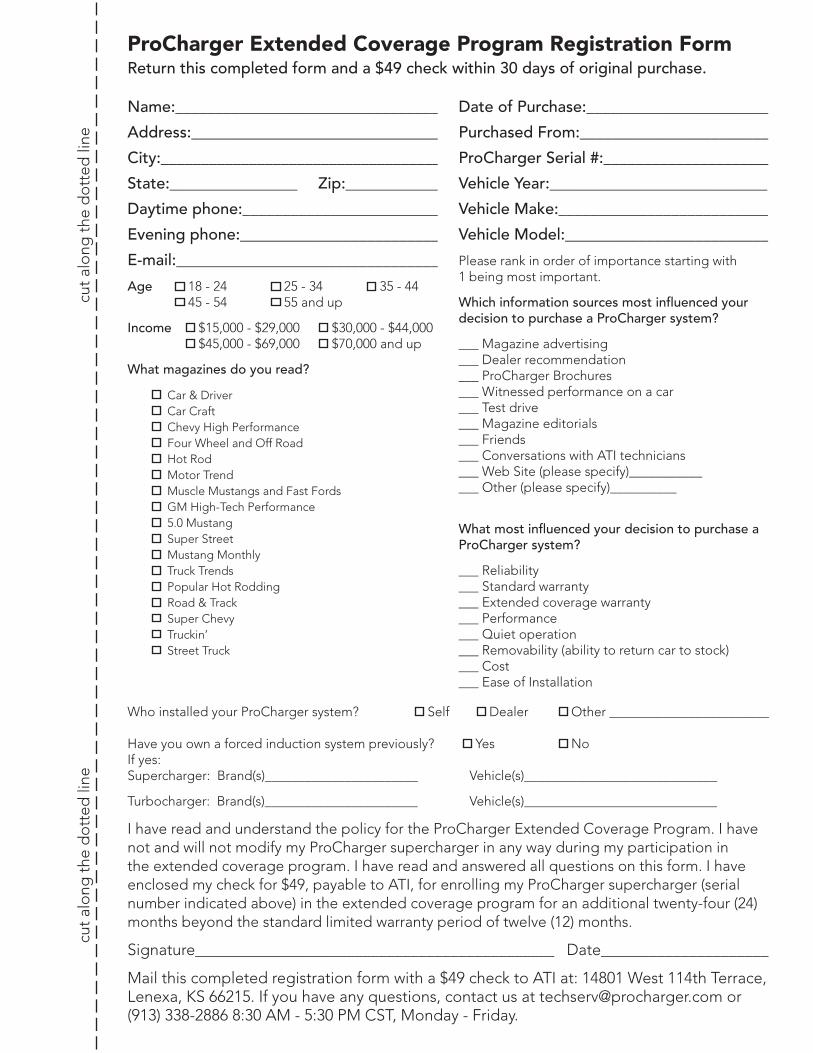
ProCharger Extended Coverage Program Registration Form
cut
alo
ng t
he d
ott
ed li
ne
cu
t al
ong
the
do
tted
line
Name:_________________________________
Address:_______________________________
City:___________________________________
State:________________ Zip:____________
Daytime phone:_________________________
Evening phone:_________________________
E-mail:_________________________________
Age 18 - 24 25 - 34 35 - 44 45 - 54 55 and up
Income $15,000 - $29,000 $30,000 - $44,000 $45,000 - $69,000 $70,000 and up
What magazines do you read?
Car & Driver Car Craft Chevy High Performance Four Wheel and Off Road Hot Rod Motor Trend Muscle Mustangs and Fast Fords GM High-Tech Performance 5.0 Mustang Super Street Mustang Monthly Truck Trends Popular Hot Rodding Road & Track Super Chevy Truckin’ Street Truck
Date of Purchase:_______________________
Purchased From:_______________________
ProCharger Serial #:_____________________
Vehicle Year:___________________________
Vehicle Make:__________________________
Vehicle Model:_________________________
Please rank in order of importance starting with 1 being most important.
Which information sources most influenced your decision to purchase a ProCharger system?
___ Magazine advertising ___ Dealer recommendation ___ ProCharger Brochures ___ Witnessed performance on a car ___ Test drive ___ Magazine editorials ___ Friends ___ Conversations with ATI technicians ___ Web Site (please specify)___________ ___ Other (please specify)__________
What most influenced your decision to purchase a ProCharger system?
___ Reliability ___ Standard warranty ___ Extended coverage warranty ___ Performance ___ Quiet operation ___ Removability (ability to return car to stock) ___ Cost ___ Ease of Installation
Who installed your ProCharger system? Self Dealer Other ________________________ Have you own a forced induction system previously? Yes No If yes: Supercharger: Brand(s)_______________________ Vehicle(s)_____________________________
Turbocharger: Brand(s)_______________________ Vehicle(s)_____________________________
I have read and understand the policy for the ProCharger Extended Coverage Program. I have not and will not modify my ProCharger supercharger in any way during my participation in the extended coverage program. I have read and answered all questions on this form. I have enclosed my check for $49, payable to ATI, for enrolling my ProCharger supercharger (serial number indicated above) in the extended coverage program for an additional twenty-four (24) months beyond the standard limited warranty period of twelve (12) months.
Signature_____________________________________________ Date_____________________
Mail this completed registration form with a $49 check to ATI at: 14801 West 114th Terrace, Lenexa, KS 66215. If you have any questions, contact us at [email protected] or (913) 338-2886 8:30 AM - 5:30 PM CST, Monday - Friday.
Return this completed form and a $49 check within 30 days of original purchase.

THIS PAGE IS INTENTIONALLY LEFT BLANK.

THIS PAGE IS INTENTIONALLY LEFT BLANK.

Accessible Technologies, Inc. ©2007 ATI, All Rights Reserved
Part Number PMGP1A-002 Rev. G
Accessible Technologies, Inc. 14801 W. 114th Terrace
Lenexa, KS 66215 Phone: 913.338.2886
Fax: 913.338.2879 [email protected]
*PMGP1A-002*