Embed Size (px)
Citation preview
Motorstarters
Motorstarters4/0
Open mounted starter components 4/2 to 4/15
GV2 combination starters 4/16 to 4/25
LEp-GB enclosed starters and enclosed contactors 4/26 to 4/31
4/1
Chapter 4
Motor starters
4
4.1
4.3
4.2
4/2
4.1
40
1
2
3
4
5
6
7
0 0,25 0,50 0,75 1
1
2
0
0,5
0 0,25 0,50 0,75 1
1
2
3
(1)1
1,5
2
2,5
TeSys motor starters - openversionStar-delta starters for motor control
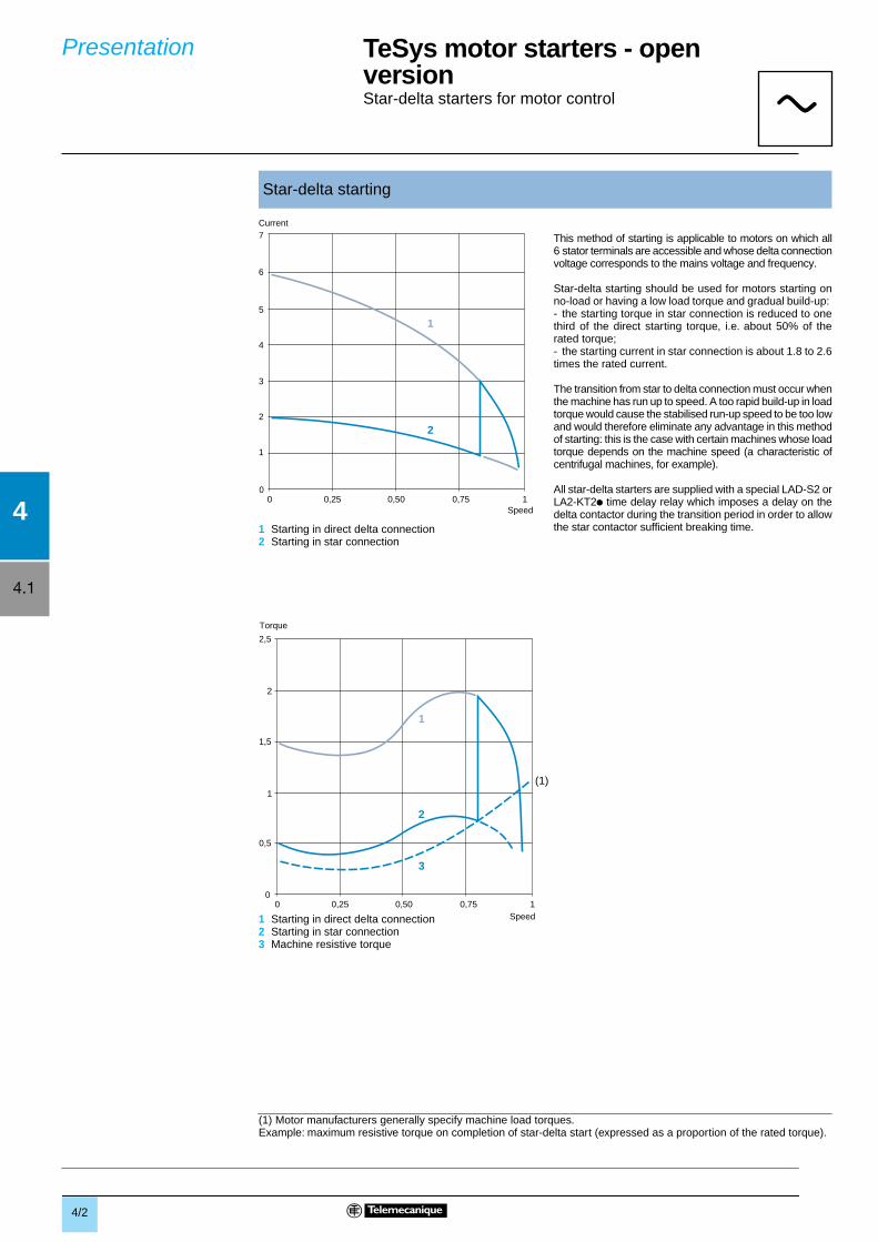
This method of starting is applicable to motors on which all6 stator terminals are accessible and whose delta connectionvoltage corresponds to the mains voltage and frequency.
Star-delta starting should be used for motors starting onno-load or having a low load torque and gradual build-up: - the starting torque in star connection is reduced to onethird of the direct starting torque, i.e. about 50% of therated torque;- the starting current in star connection is about 1.8 to 2.6times the rated current.
The transition from star to delta connection must occur whenthe machine has run up to speed. A too rapid build-up in loadtorque would cause the stabilised run-up speed to be too lowand would therefore eliminate any advantage in this methodof starting: this is the case with certain machines whose loadtorque depends on the machine speed (a characteristic ofcentrifugal machines, for example).
All star-delta starters are supplied with a special LAD-S2 orLA2-KT2p time delay relay which imposes a delay on thedelta contactor during the transition period in order to allowthe star contactor sufficient breaking time.
1 Starting in direct delta connection2 Starting in star connection3 Machine resistive torque
(1) Motor manufacturers generally specify machine load torques. Example: maximum resistive torque on completion of star-delta start (expressed as a proportion of the rated torque).
Star-delta starting
Presentation
aaaa
Current
Speed
Speed
Torque
1 Starting in direct delta connection2 Starting in star connection
4/3
4.1
4
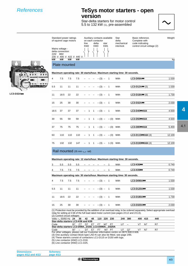
TeSys motor starters - openversionStar-delta starters for motor control5.5 to 132 kW (1), pre-assembled
delta connection
Maximum operating rate: 30 starts/hour. Maximum starting time: 30 seconds.
Maximum operating rate: 12 starts/hour. Maximum starting time: 30 seconds.
(1) Protection must be provided by the addition of an overload relay, to be ordered separately. Select appropriate overloadrelay for setting at 0.58 of the full load rated motor current (see pages 2/112 and 2/113).(2) Control circuit voltages
Star-delta starters LC3-K06 and K09
Star-delta starters LC3-D09A...D150, LC3-D090A…D320A
For other voltages, please call our Customer information centre on 0870 608 8 608.(3) One auxiliary contact block type LAD-N can also be fitted, see page 2/85.(4) These starters consist of contactors LC1-D115 or D150 with lugs.(5) Line contactor (KM2) LC1-D18.(6) Line contactor (KM2) LC1-D25.
Standard power ratings Auxiliary contacts available Star Basic reference. Weightof squirrel cage motors on each contactor delta Complete with
line delta star mechanical code indicatingKM2 KM3 KM1 interlock control circuit voltage (2)
Mains voltage -
220/ 380/230 V 400 V 415 V 440 VkW kW kW kW kg
Plate mounted
4 7.5 7.5 7.5 – – – – (3) – 1 With LC3-D09App 1.530
5.5 11 11 11 – – – – (3) – 1 With LC3-D12App (5) 1.530
11 18.5 22 22 – – – – (3) – 1 With LC3-D18App (6) 1.730
15 25 30 30 – – – – (3) – 1 With LC3-D32App 2.030
18.5 37 37 37 – 1 1 – (3) – 1 With LC3-D40ppA64 4.500
30 55 59 59 – 1 1 – (3) – – (3) With LC3-D50ppA64 4.500
37 75 75 75 – 1 1 – (3) – – (3) With LC3-D80ppA64 5.400
63 110 110 110 – 1 1 – (3) – – (3) With LC3-D115ppA64 (4) 12.100
75 132 132 147 – 1 1 – (3) – 1 (3) With LC3-D150ppA64 (4) 12.100
Rail mounted (35 mm 7 rail)
3 5.5 5.5 5.5 – – – – – 1 With LC3-K06pp 0.740
4 7.5 7.5 7.5 – – – – – 1 With LC3-K09pp 0.740
Maximum operating rate: 30 starts/hour. Maximum starting time: 30 seconds.
4 7.5 7.5 7.5 – – – – (3) – 1 With LC3-D090App 1.530
5.5 11 11 11 – – – – (3) – 1 With LC3-D120App 1.530
11 18.5 22 22 – – – – (3) – 1 With LC3-D180App 1.730
15 25 30 30 – – – – (3) – 1 With LC3-D320App 2.030
Volts a 50/60 Hz 24 36 42 48 110 220 230 240 380 400 415 440
Code B7 C7 D7 E7 F7 M7 P7 U7 – V7 N7 R7
Code B7 – D7 E7 F7 M7 P7 U7 Q7 V7 N7 R7
References
LC3-D32App
aaaa
Dimensions:pages 4/12 and 4/13
Schemes:page 4/13
4/4
4.1
4KM2
KM2
KM2
1c
1c 1a
1b
1d
1b
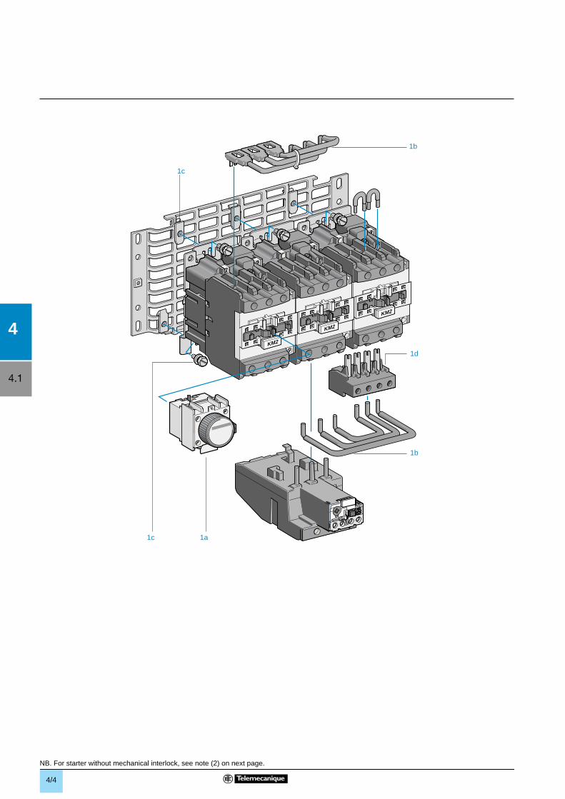
NB. For starter without mechanical interlock, see note (2) on next page.
4/5
4.1
4
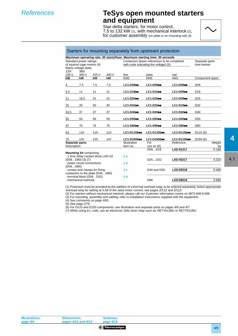
TeSys open mounted starters and equipmentStar-delta starters, for motor control,7.5 to 132 kW (1), with mechanical interlock (2),for customer assembly (on plate or on mounting rail) (3)
Maximum operating rate: 30 starts/hour. Maximum starting time: 30 seconds
(1) Protection must be provided by the addition of a thermal overload relay, to be ordered separately. Select appropriateoverload relay for setting at 0.58 of the rated motor current, see pages 2/112 and 2/113.(2) For starters without mechanical interlock, please call our Customer information centre on 0870 608 8 608.(3) For mounting, assembly and cabling: refer to installation instructions supplied with the equipment.(4) See comments on page 4/92.(5) See page 2/76.(6) For D115 and D150 components, see illustration and separate parts on pages 4/6 and 4/7.(7) When using d.c. coils, use an electronic Zelio timer relay such as: RE7YA12BU or RE7YR12BU.
Starters for mounting separately from upstream protection
Standard power ratings Contactors (basic references to be completed Separate partsof squirrel cage motors (4) with code indicating the voltage) (5) (see below)Mains voltage-delta220/ 380/230 V 400 V 415 V 440 V line delta starkW kW kW kW KM2 KM3 KM1 Component types
4 7.5 7.5 7.5 LC1-D09pp LC1-D09pp LC1-D09pp D09
5.5 11 11 11 LC1-D18pp LC1-D12pp LC1-D09pp D18
11 18.5 22 22 LC1-D25pp LC1-D25pp LC1-D09pp D25
15 25 30 30 LC1-D32pp LC1-D32pp LC1-D18pp D32
18.5 37 37 37 LC1-D40pp LC1-D40pp LC1-D40pp D40
30 55 59 59 LC1-D50pp LC1-D50pp LC1-D40pp D50
37 75 75 75 LC1-D80pp LC1-D80pp LC1-D80pp D80
63 110 110 110 LC1-D1156pp LC1-D1156pp LC1-D1156pp D115 (6)
75 132 132 147 LC1-D1506pp LC1-D1506pp LC1-D1156pp D150 (6)Separate parts Illustration For Reference WeightDescription item no. use on (6) kg
D09…D18 LAD-91217 0.180Mounting kit comprising:- 1 time delay contact block LAD-S2 1 a(D09…D80) (3) (7) D25....D32 LAD-93217 0.310- power circuit connections 1 b(D09…D80)- screws and clamps for fixing 1 c D40 and D50 LA9-D5018 0.480contactors to the plate (D40…D80)- terminal block (D09…D32) 1 d- mechanical interlock D80 LA9-D8018 0.680
References
a
Illustrations:page 4/4
Dimensions: pages 4/12 and 4/13
Schemes:page 4/13
4/6
4.1
4
11 4 10 7 9 8
3
12
5
5
521
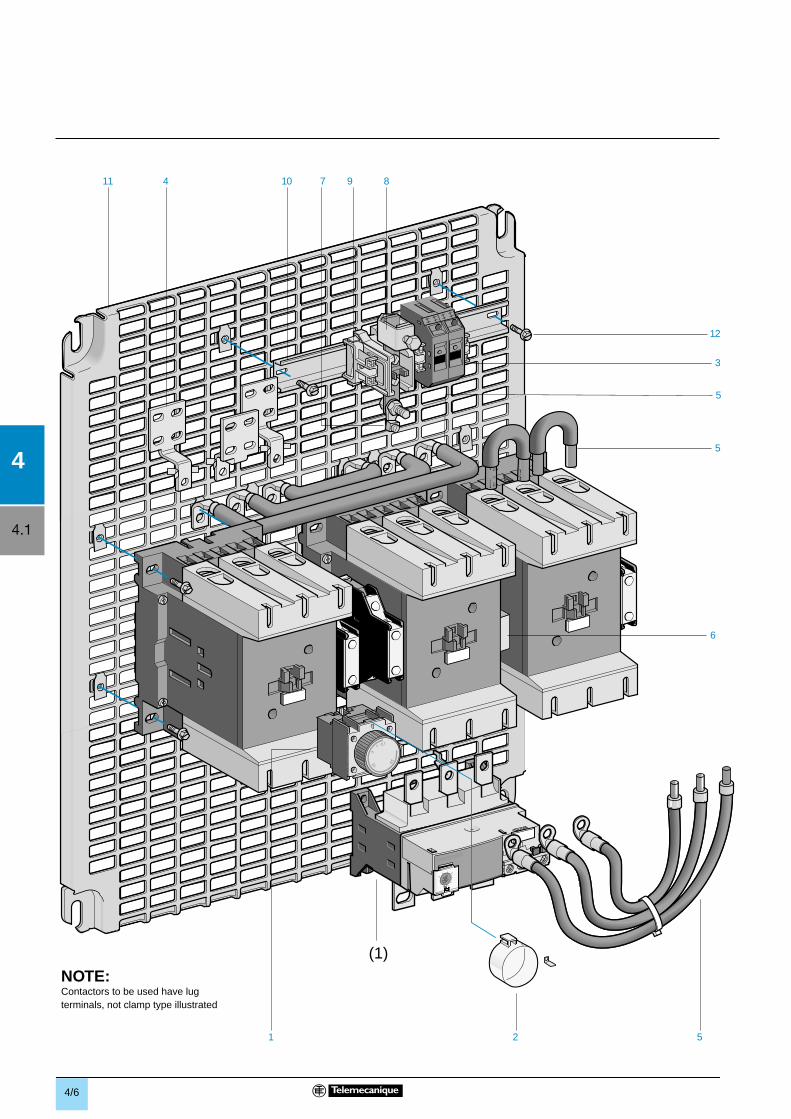
(1)NOTE:Contactors to be used have lug terminals, not clamp type illustrated
6
4/7
4.1
4
TeSys open mounted starters and equipmentStar-delta starters, for motor control,7.5 to 132 kW (1)
for customer assembly (on plate or on mounting rail) (2)
(1) Protection must be provided by the addition of a thermal overload relay, to be ordered separately. Select appropriateoverload relay for setting at 0.58 of the rated motor current, see pages 2/112 and 2/113.(2) For mounting, assembly and cabling: refer to installation instructions supplied with the equipment.(3) For use with 2 D115 and 1 D80.
Separate parts (continued)
Description Illustration For No. Sold in Unit Weightitem no. use on lots of reference kg
Time delay auxiliary 1 D115, D150 1a 1 LAD-S2 (2) 0.060contact blocks orelectronic timer
Sealing kit for 2 D115, D150 1 1 LA9-D901 0.005time delay auxiliarycontact blocks
Thermal magnetic 3 D115, D150 2 6 GB2-CB05 0.060circuit-breaker forcontrol circuit (200…415 V)
Set of 3 connectors for 4 D115, D150 1 1 LA9-FG980 0.200wider terminations (optional)
Set of power connections 5 D115, D150 1 1 LA9-D15017 1.050with fixing accessories
D115 1 1 LA9-D11517(3)
Mechanical interlock 6 D115, D150 1 1 LA9-D11502 0.280
Spare volt free terminals 7 D115, D150 1 10 DZ3-HA3 0.007
2 10 DZ3-GA3 0.006
Lug-connector 8 D115, D150 1 10 AB1-BC9535 0.236terminal block
Terminal end stop 9 D115, D150 3 100 AB1-AB8M35 0.005
Mounting rail 5 35 mm 10 D115, D150 1 10 AM1-ED021 0.210
Pre-slotted plate 11 D115, D150 1 1 AM3-PA65 1.950
Screw with captive washer 12 D115, D150 12 100 AF1-VA618 0.006
2 100 AF1-VA410 0.002
References (continued)
a
Illustrations:page 4/6
Dimensions: pages 4/12 and 4/13
Schemes:page 4/13
4/8
4
4.1
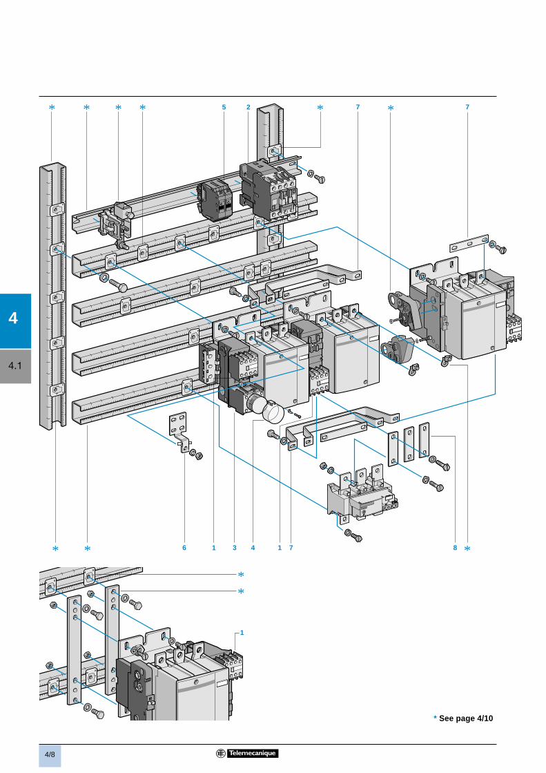
1
**
8
* 5 2 7 7
714316*
* * *
*
*
*
*
* See page 4/10
4/9
4.1
4
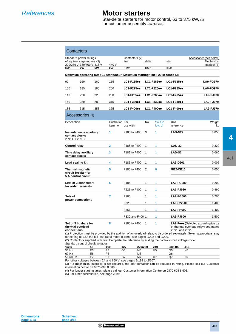
Contactors
Standard power ratings Contactors (2) Accessories (see below)of squirrel cage motors (3) line delta star Mechanical220/230 V 380/400 V 415 V 440 V interlock (3)kW kW kW kW KM2 KM3 KM1
Maximum operating rate : 12 starts/hour. Maximum starting time : 20 seconds (3)
90 160 160 185 LC1-F185ii LC1-F185ii LC1-F185ii LA9-FG970
100 185 185 200 LC1-F225ii LC1-F225ii LC1-F225ii LA9-FG970
110 220 220 250 LC1-F265ii LC1-F265ii LC1-F265ii LA9-FJ970
160 280 280 315 LC1-F330ii LC1-F330ii LC1-F330ii LA9-FJ970
185 315 355 375 LC1-F400ii LC1-F400ii LC1-F400ii LA9-FJ970
Accessories (4)
Description Illustration For No. Sold in Unit Weightitem no. use with lots of reference kg
Instantaneous auxiliary 1 F185 to F400 3 1 LAD-N22 0.050contact blocks2 N/O + 2 N/C
Control relay 2 F185 to F400 1 1 CAD-32 0.320
Time delay auxiliary 3 F185 to F400 1 1 LAD-S2 0.060contact blocks
Lead sealing kit 4 F185 to F400 1 1 LA9-D901 0.005
Thermal magnetic 5 F185 to F400 2 6 GB2-CB10 0.050circuit breaker for5 A control circuit
Sets of 3 connectors 6 F185 1 1 LA9-FG980 0.200for wider terminals
F225 to F400 1 1 LA9-FJ980 0.490
Sets of 7 F185 1 1 LA9-FG600 0.700power connections
F225 1 1 LA9-F22500 1.400
F265 1 1 LA9-FH600 1.400
F330 and F400 1 1 LA9-FJ600 1.500
Set of 3 busbars for 8 F185 to F400 1 1 LA7-Fiii (Selected according to sizethermal overload of thermal overload relay) see pagesconnections 2/228 and 2/229.(1) Protection must be provided by the addition of an overload relay, to be ordered separately. Select appropriate relayfor setting at 0.58 the full load rated motor current, see pages 2/228 and 2/229.(2) Contactors supplied with coil. Complete the reference by adding the control circuit voltage code.Standard control circuit voltages.Volts 48 110 127 220/230 240 380/400 41550 Hz E5 F5 G5 M5 U5 Q5 N560 Hz E6 F6 – M6 – Q6 –50/60 Hz E7 F7 G7 M7 U7 Q7 N7For other voltages between 24 and 660 V, see pages 2/198 to 2/207.(3) If a mechanical interlock is not required, the star contactor can be reduced in rating. Please call our Customerinformation centre on 0870 608 8 608.(4) For longer starting times, please call our Customer Information Centre on 0870 608 8 608.(5) For other accessories, see page 2/196.
Dimensions: Schemes:page 4/14 page 4/15
Motor startersStar-delta starters for motor control, 63 to 375 kW, (1)
for customer assembly (on chassis)
References

4/10
4
4.1
* See page 4/8
12
14 *
*13 1115 18 ** 16 * 9
10******17
*
18
4/11
4.1
4
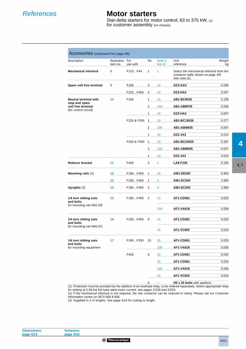
Accessories (continued from page 4/9)
Description Illustration For No. Sold in Unit Weightitem no. use with lots of reference kg
Mechanical interlock 9 F115…F44 1 1 Select the mechanical interlock from thecontactor table shown on page 4/9.See note (2).
Spare volt free terminal 9 F185 3 10 DZ3-GA3 0.006
F225…F400 3 10 DZ3-HA3 0.007
Neutral terminal with 10 F185 1 10 AB1-BC9535 0.236stop and sparevolt free terminal 2 100 AB1-AB8P35 0.006(for control circuit)
1 10 DZ3-HA3 0.007
F225 & F265 1 10 AB1-BC15035 0.277
2 100 AB1-AB8M35 0.007
1 10 DZ3-JA3 0.010
F330 & F400 1 10 AB1-BC24035 0.287
2 100 AB1-AB8M35 0.007
1 10 DZ3-JA3 0.010
Reducer bracket 11 F400 2 1 LA9-F100 0.100
Mounting rails (3) 12 F185…F400 1 10 AM1-DE200 0.900
13 F185…F400 1 4 AM1-EC200 2.980
Uprights (3) 14 F185…F400 2 4 AM1-EC200 2.980
1/4 turn sliding nuts 15 F185…F400 2 10 AF1-CD061 0.020and boltsfor mounting rail AM1-DE
100 AF1-VA618 0.006
1/4 turn sliding nuts 16 F185…F400 8 10 AF1-CD081 0.020and boltsfor mounting rail AM1-EC
10 AF1-VC820 0.024
1/4 turn sliding nuts 17 F185…F330 15 10 AF1-CD061 0.020and boltsfor mounting equipment 100 AF1-VA618 0.006
F400 8 10 AF1-CD061 0.020
10 AF1-CD081 0.020
100 AF1-VA618 0.006
10 AF1-VC820 0.024
4 – H6 x 25 bolts with washers(1) Protection must be provided by the addition of an overload relay, to be ordered separately. Select appropriate relayfor setting at 0.58 the full load rated motor current, see pages 2/228 and 2/229.(2) If the mechanical interlock is not required, the star contactor can be reduced in rating. Please call our Customerinformation centre on 0870 608 8 608.(3) Supplied in 2 m lengths. See page 4/14 for cutting to length.
Dimensions: Schemes:page 4/14 page 4/15
Motor startersStar-delta starters for motor control, 63 to 375 kW, (1)
for customer assembly (on chassis)
References
4/12
4.1
4
94
110
175
150
175 (1)
4514
3
263
281
==
60
=10
0/11
0
==
=
a
G
H
c
b
c 4
124
b
90= =
a
110KM2
KM3 KM1
110
183 (1)
4714
3
293
311
==
60
=10
0/11
0
==
=
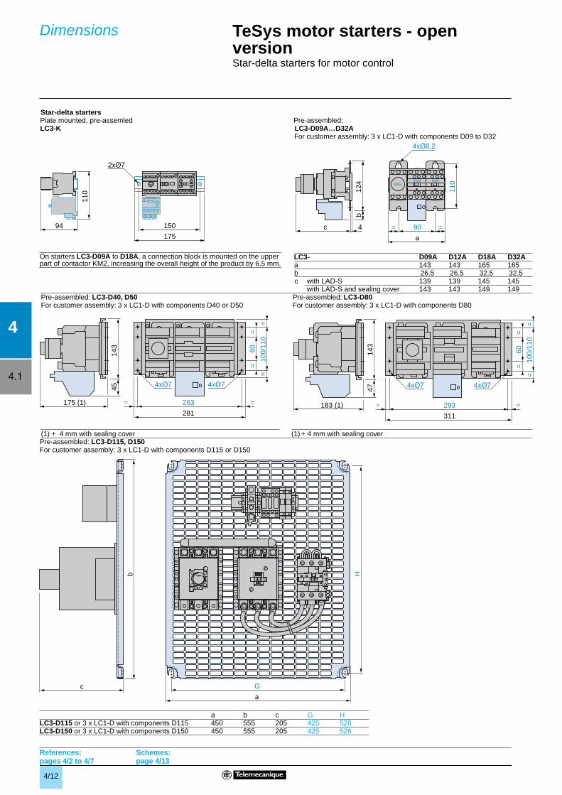
Dimensions TeSys motor starters - open version 1
Star-delta starters for motor control
Star-delta starters
Pre-assembled: LC3-D115, D150For customer assembly: 3 x LC1-D with components D115 or D150
Plate mounted, pre-assemled Pre-assembled: LC3-K LC3-D09A…D32A
For customer assembly: 3 x LC1-D with components D09 to D32
LC3- D09A D12A D18A D32Aa 143 143 165 165b 26.5 26.5 32.5 32.5c with LAD-S 139 139 145 145
with LAD-S and sealing cover 143 143 149 149Pre-assembled: LC3-D40, D50 Pre-assembled: LC3-D80For customer assembly: 3 x LC1-D with components D40 or D50 For customer assembly: 3 x LC1-D with components D80
(1) + 4 mm with sealing cover (1) + 4 mm with sealing cover
a b c G HLC3-D115 or 3 x LC1-D with components D115 450 555 205 425 526LC3-D150 or 3 x LC1-D with components D150 450 555 205 425 526
References: pages 4/2 to 4/7
Schemes: page 4/13
On starters LC3-D09A to D18A, a connection block is mounted on the upper part of contactor KM2, increasing the overall height of the product by 6.5 mm.
4/13
4.1
4
c
b
2xØ7
160
175
KM2KM3 KM1
U1
V1
W1
U2
V2
W2
2 4 6
– KM2
12
34
56
– KM3
12
34
56
– KM1
12
34
56
U1
V1
W1
U2
V2
W2
1 3 5
2 4 6
L1 L2 L3
(1)
KM2 : 1 (N)
O
T
T
I
Y
L
KM3 : 5
– KM3 – KM2– KM1
– KM154 53
A1
A2
A1
A2
A1
A2
A1
A2
– KM1– KM3
2122
2221
1516
9596
– KM2
1413
A1
A2
– KM1
1314
2122
2221
– KM355
56
– KM2
5354
– KM1
9596
KM3/5
O
l
6867
– KM2
A1
A2
– KM3
2122
– KM1
A1
A2
– KM2
1413
– KM2
KM3/1
N
(14)
(13)
Remotecontrol
– KM2
12
34
56
– KM3
12
34
56
– KM1
12
34
56
U1
V1
W1
U2
V2
W2
1 3 5
2 4 6
L1 L2 L3
U1
V1
W1
U2
V2
W2
2 4 6
Recommendedcabling for reversal of motor rotation (standard motor, viewed from shaft end).
A1
A2
– KM1
1314
2122
162
161
– KM3
5556
– KM2
184
183
– KM1
9596
– F1
– F1
O
l
153
154
– KM2
A1
A2
– KA1
A1
A2
– KM2
153
154
– KM1
– F2
171
6768
– KM2
172
– KM1
1314
A1
A2
– KM3
– KA1
Y L
Remotecontrol
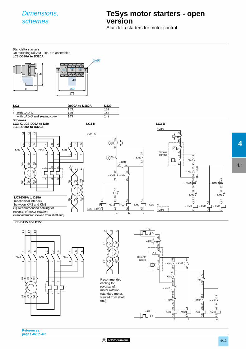
Dimensions,schemes
TeSys motor starters - open version 1
Star-delta starters for motor control
References: pages 4/2 to 4/7
Star-delta startersOn mounting rail AM1-DP, pre-assembledLC3-D090A to D320A
Schemes
LC3-D090A to D320A
LC3-D115 and D150
LC3- D090A to D180A D320b 153 137c with LAD-S 139 145
with LAD-S and sealing cover 143 149
LC3-K, LC3-D09A to D80 LC3-K LC3-D
LC3-D09A to D18Amechanical interlockbetween KM3 and KM1(1) Recommended cabling forreversal of motor rotation(standard motor, viewed from shaft end)
4/14
4
4.1
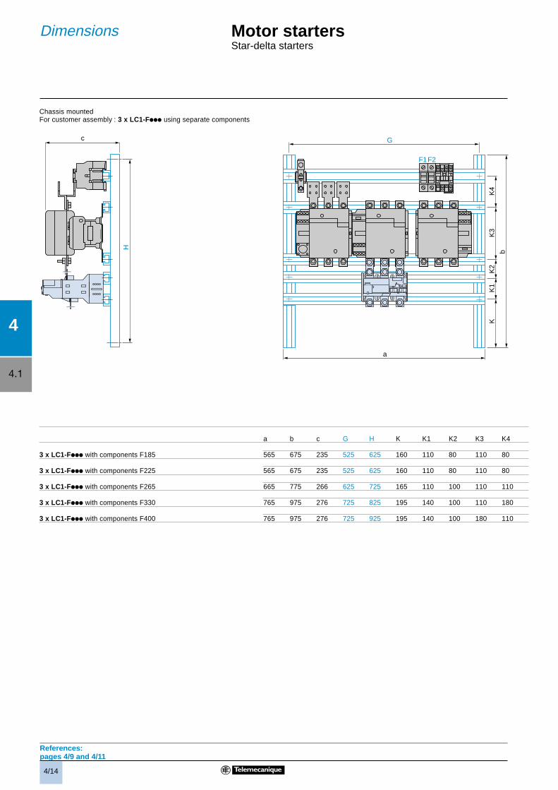
Chassis mountedFor customer assembly : 3 x LC1-Fiii using separate components
a b c G H K K1 K2 K3 K4
3 x LC1-Fiii with components F185 565 675 235 525 625 160 110 80 110 80
3 x LC1-Fiii with components F225 565 675 235 525 625 160 110 80 110 80
3 x LC1-Fiii with components F265 665 775 266 625 725 165 110 100 110 110
3 x LC1-Fiii with components F330 765 975 276 725 825 195 140 100 110 180
3 x LC1-Fiii with components F400 765 975 276 725 925 195 140 100 180 110
KM3KM2 KM1
b
a
G
KK
1K
2K
3K
4
F1F2
c
H
References:pages 4/9 and 4/11
Motor startersStar-delta starters
Dimensions
4/15
4.1
4
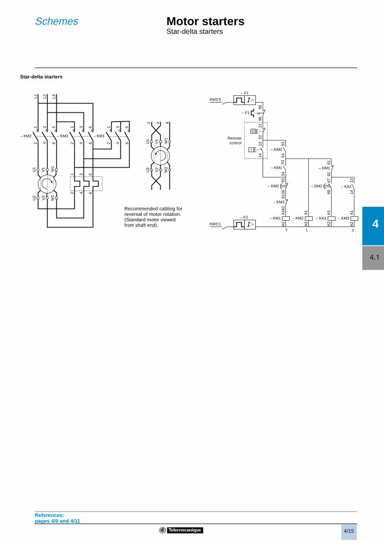
Star-delta starters
Recommended cabling forreversal of motor rotation.(Standard motor viewedfrom shaft end).
– KM2
12
34
56
– KM3
12
34
56
– KM1
12
34
56
U1
V1
W1
U2
V2
W2
1 3 5
2 4 6
L1 L2 L3
U1
V1
W1
U2
V2
W2
2 4 6
Y L Δ
Remotecontrol
A1
A2
– KM1
1314
2122
6261
– KM3
5556
– KM2
5354
– KM1
9596
– F1
– F1
KM3:5
O
l
6768
– KM2
A1
A2
– KA1
A1
A2
– KM2
5354
– KM2
– F2
KM3:1
6261
– KM1
1314
A1
A2
– KM3
– KA1
References:pages 4/9 and 4/11
Motor startersStar-delta starters
Schemes
4/16
4
4.2
90° 90°
30° 30° 30° 30°
90° 90°
General
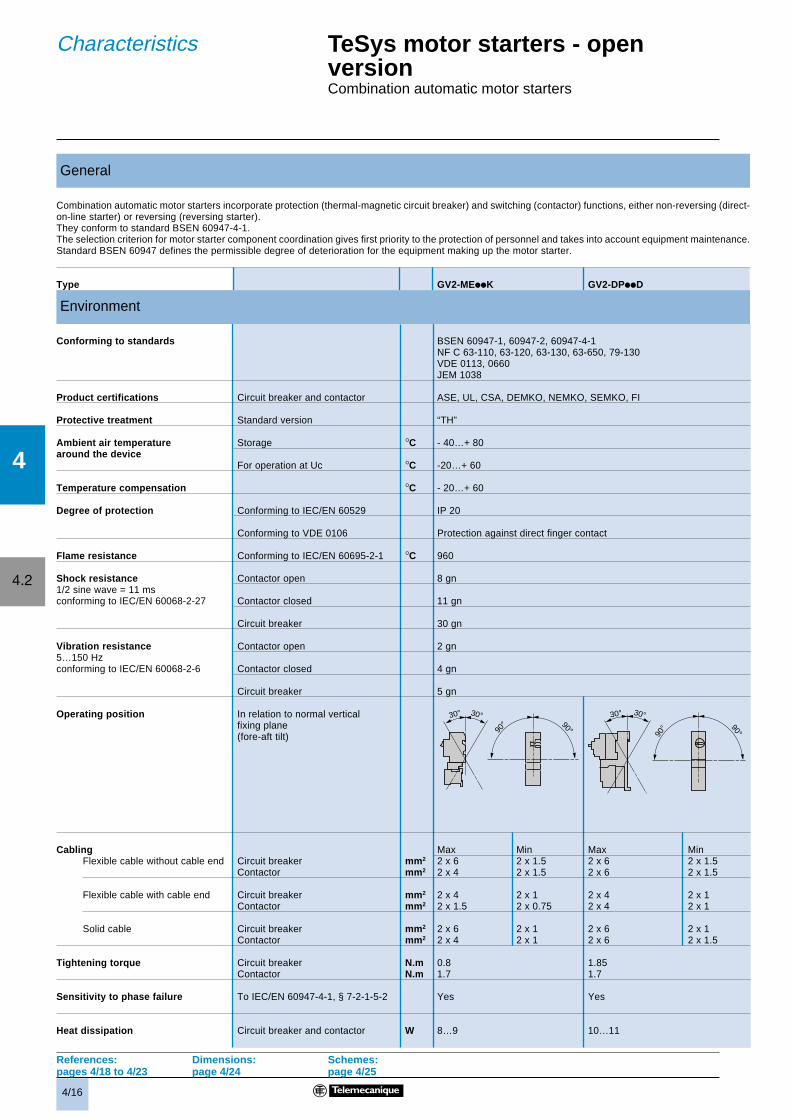
Combination automatic motor starters incorporate protection (thermal-magnetic circuit breaker) and switching (contactor) functions, either non-reversing (direct-on-line starter) or reversing (reversing starter).They conform to standard BSEN 60947-4-1.The selection criterion for motor starter component coordination gives first priority to the protection of personnel and takes into account equipment maintenance.Standard BSEN 60947 defines the permissible degree of deterioration for the equipment making up the motor starter.
Type GV2-MEiiK GV2-DPiiD
Environment
Conforming to standards BSEN 60947-1, 60947-2, 60947-4-1NF C 63-110, 63-120, 63-130, 63-650, 79-130VDE 0113, 0660JEM 1038
Product certifications Circuit breaker and contactor ASE, UL, CSA, DEMKO, NEMKO, SEMKO, FI
Protective treatment Standard version “TH”
Ambient air temperature Storage °C - 40…+ 80around the device
For operation at Uc °C -20…+ 60
Temperature compensation °C - 20…+ 60
Degree of protection Conforming to IEC/EN 60529 IP 20
Conforming to VDE 0106 Protection against direct finger contact
Flame resistance Conforming to IEC/EN 60695-2-1 °C 960
Shock resistance Contactor open 8 gn1/2 sine wave = 11 msconforming to IEC/EN 60068-2-27 Contactor closed 11 gn
Circuit breaker 30 gn
Vibration resistance Contactor open 2 gn5…150 Hzconforming to IEC/EN 60068-2-6 Contactor closed 4 gn
Circuit breaker 5 gn
Operating position In relation to normal verticalfixing plane(fore-aft tilt)
Cabling Max Min Max MinFlexible cable without cable end Circuit breaker mm2 2 x 6 2 x 1.5 2 x 6 2 x 1.5
Contactor mm2 2 x 4 2 x 1.5 2 x 6 2 x 1.5
Flexible cable with cable end Circuit breaker mm2 2 x 4 2 x 1 2 x 4 2 x 1Contactor mm2 2 x 1.5 2 x 0.75 2 x 4 2 x 1
Solid cable Circuit breaker mm2 2 x 6 2 x 1 2 x 6 2 x 1Contactor mm2 2 x 4 2 x 1 2 x 6 2 x 1.5
Tightening torque Circuit breaker N.m 0.8 1.85Contactor N.m 1.7 1.7
Sensitivity to phase failure To IEC/EN 60947-4-1, § 7-2-1-5-2 Yes Yes
Heat dissipation Circuit breaker and contactor W 8…9 10…11
References: Dimensions: Schemes:pages 4/18 to 4/23 page 4/24 page 4/25
TeSys motor starters - openversionCombination automatic motor starters
Characteristics
4/17
4
4.2
Type GV2- MEiiK1 MEiiK2 DPiiD1 DPiiD2
Control circuit characteristics
Control voltage range ≤ 50 °C 50/60 Hz coil 0.8…1.15 Uc 0.8…1.1 Uc
a coil 0.7…1.3 Uc 0.7…1.25 Uc
Consumption at 20 °C c 50/60 Hz Inrush VA 30 100and at Uc
Sealed VA 4.5 8.5
a Inrush W 1.5 1.5
Sealed W 1.5 1.5
Operating time c 50/60 Hz N/O ms 5…15 15…24at 20 °C and at Uc
N/C ms 10…20 5…19
a N/O ms 10…20 50
N/C ms 15…25 15
Technical characteristics
Operational current in cat. AC-3 Up to A 9 25
Rated operational current (Ue) Conforming to IEC/EN 60947 V 690 690
Rated insulation voltage (Ui) Conforming to IEC/EN 60947 V 690 690
Conforming to CSA 22-2 n° 14 V 600 600
Rated operational frequency Conforming to IEC/EN 60947 Hz 50/60 50/60
Rated making capacity I rms A 110 450
Rated breaking capacity I rms 220…440 V A 110 450
500 V A 80 400
660…690 V A 70 180
Mechanical durability at Uc In millions ofoperating 50/60 Hz 10 5 12 5cycles
a 30 5 30 5
Electrical durability In millions of See Lii-K09 See Lii-D25in category AC-3 at Ie max operatingand Ue = 415 V cycles
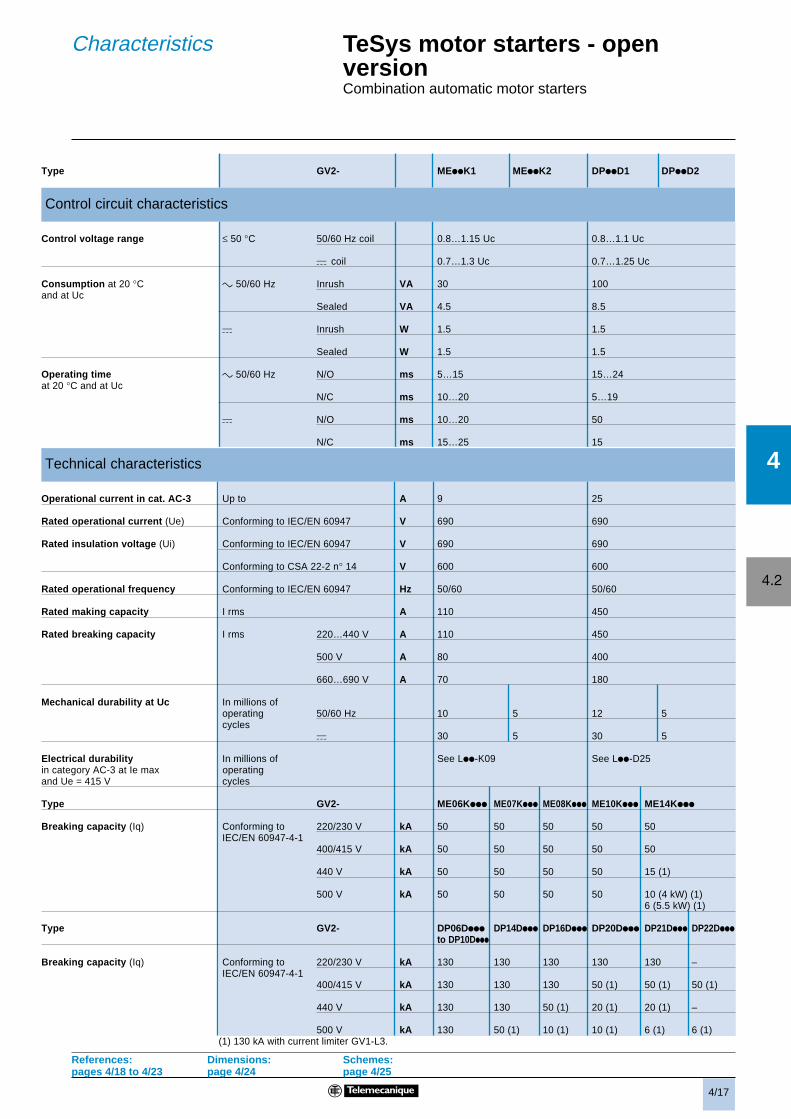
Type GV2- ME06Kiii ME07Kiii ME08Kiii ME10Kiii ME14Kiii
Breaking capacity (Iq) Conforming to 220/230 V kA 50 50 50 50 50IEC/EN 60947-4-1
400/415 V kA 50 50 50 50 50
440 V kA 50 50 50 50 15 (1)
500 V kA 50 50 50 50 10 (4 kW) (1)6 (5.5 kW) (1)
Type GV2- DP06Diii DP14Diii DP16Diii DP20Diii DP21Diii DP22Diii
to DP10Diii
Breaking capacity (Iq) Conforming to 220/230 V kA 130 130 130 130 130 –IEC/EN 60947-4-1
400/415 V kA 130 130 130 50 (1) 50 (1) 50 (1)
440 V kA 130 130 50 (1) 20 (1) 20 (1) –
500 V kA 130 50 (1) 10 (1) 10 (1) 6 (1) 6 (1)(1) 130 kA with current limiter GV1-L3.
References: Dimensions: Schemes:pages 4/18 to 4/23 page 4/24 page 4/25
TeSys motor starters - openversionCombination automatic motor starters
Characteristics
4/18
4
4.2
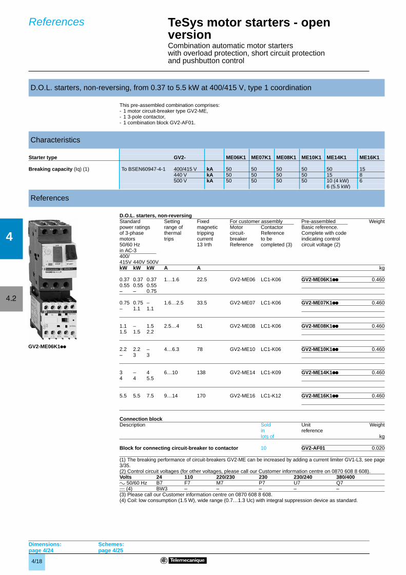
This pre-assembled combination comprises:- 1 motor circuit-breaker type GV2-ME,- 1 3-pole contactor,- 1 combination block GV2-AF01.
D.O.L. starters, non-reversing
(1) The breaking performance of circuit-breakers GV2-ME can be increased by adding a current limiter GV1-L3, see page3/35.(2) Control circuit voltages (for other voltages, please call our Customer information centre on 0870 608 8 608).
(3) Please call our Customer information centre on 0870 608 8 608.(4) Coil: low consumption (1.5 W), wide range (0.7…1.3 Uc) with integral suppression device as standard.
D.O.L. starters, non-reversing, from 0.37 to 5.5 kW at 400/415 V, type 1 coordination
Characteristics
Starter type GV2- ME06K1 ME07K1 ME08K1 ME10K1 ME14K1 ME16K1
Breaking capacity (Iq) (1) To BSEN60947-4-1 400/415 V kA 50 50 50 50 50 15440 V kA 50 50 50 50 15 8500 V kA 50 50 50 50 10 (4 kW) 6
6 (5.5 kW)
References
Standard Setting Fixed For customer assembly Pre-assembled Weightpower ratings range of magnetic Motor Contactor Basic reference.of 3-phase thermal tripping circuit- Reference Complete with codemotors trips current breaker to be indicating control50/60 Hz 13 Irth Reference completed (3) circuit voltage (2)in AC-3400/415V 440V 500VkW kW kW A A kg
0.37 0.37 0.37 1…1.6 22.5 GV2-ME06 LC1-K06 GV2-ME06K1pppppppp 0.4600.55 0.55 0.55– – 0.75
0.75 0.75 – 1.6…2.5 33.5 GV2-ME07 LC1-K06 GV2-ME07K1pppppppp 0.460– 1.1 1.1
1.1 – 1.5 2.5…4 51 GV2-ME08 LC1-K06 GV2-ME08K1pppppppp 0.4601.5 1.5 2.2
2.2 2.2 – 4…6.3 78 GV2-ME10 LC1-K06 GV2-ME10K1pppppppp 0.460– 3 3
3 – 4 6…10 138 GV2-ME14 LC1-K09 GV2-ME14K1pppppppp 0.4604 4 5.5
5.5 5.5 7.5 9…14 170 GV2-ME16 LC1-K12 GV2-ME16K1pppppppp 0.460
Connection blockDescription Sold Unit Weight
in referencelots of kg
Block for connecting circuit-breaker to contactor 10 GV2-AF01 0.020
Volts 24 110 220/230 230 230/240 380/400a 50/60 Hz B7 F7 M7 P7 U7 Q7c (4) BW3 – – – – –
GV2-ME06K1pp
TeSys motor starters - open versionCombination automatic motor starterswith overload protection, short circuit protection and pushbutton control
References
Dimensions:page 4/24
Schemes:page 4/25
4/19
4
4.2
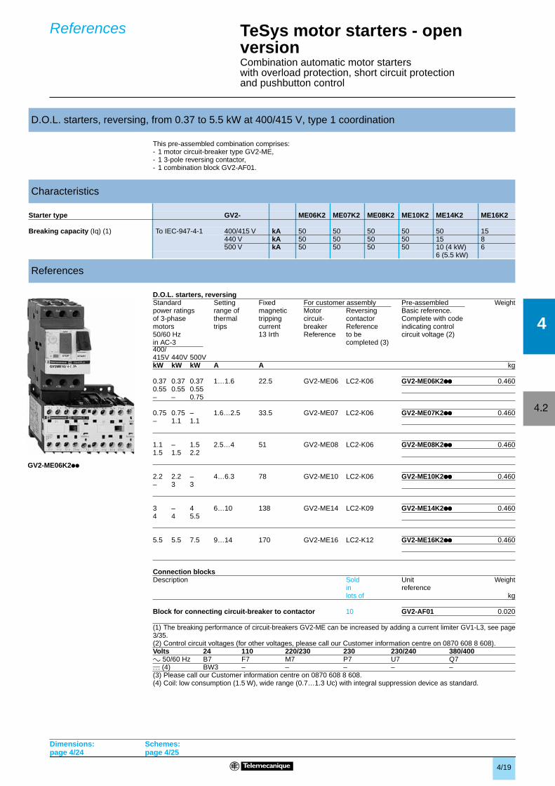
This pre-assembled combination comprises:- 1 motor circuit-breaker type GV2-ME,- 1 3-pole reversing contactor,- 1 combination block GV2-AF01.
D.O.L. starters, reversing
400/
(1) The breaking performance of circuit-breakers GV2-ME can be increased by adding a current limiter GV1-L3, see page3/35.(2) Control circuit voltages (for other voltages, please call our Customer information centre on 0870 608 8 608).
(3) Please call our Customer information centre on 0870 608 8 608.(4) Coil: low consumption (1.5 W), wide range (0.7…1.3 Uc) with integral suppression device as standard.
D.O.L. starters, reversing, from 0.37 to 5.5 kW at 400/415 V, type 1 coordination
Characteristics
Starter type GV2- ME06K2 ME07K2 ME08K2 ME10K2 ME14K2 ME16K2
Breaking capacity (Iq) (1) To IEC-947-4-1 400/415 V kA 50 50 50 50 50 15440 V kA 50 50 50 50 15 8500 V kA 50 50 50 50 10 (4 kW) 6
6 (5.5 kW)
References
Standard Setting Fixed For customer assembly Pre-assembled Weightpower ratings range of magnetic Motor Reversing Basic reference.of 3-phase thermal tripping circuit- contactor Complete with codemotors trips current breaker Reference indicating control50/60 Hz 13 Irth Reference to be circuit voltage (2)in AC-3 completed (3)
415V 440V 500VkW kW kW A A kg
0.37 0.37 0.37 1…1.6 22.5 GV2-ME06 LC2-K06 GV2-ME06K2pppppppp 0.4600.55 0.55 0.55– – 0.75
0.75 0.75 – 1.6…2.5 33.5 GV2-ME07 LC2-K06 GV2-ME07K2pppppppp 0.460– 1.1 1.1
1.1 – 1.5 2.5…4 51 GV2-ME08 LC2-K06 GV2-ME08K2pppppppp 0.4601.5 1.5 2.2
2.2 2.2 – 4…6.3 78 GV2-ME10 LC2-K06 GV2-ME10K2pppppppp 0.460– 3 3
3 – 4 6…10 138 GV2-ME14 LC2-K09 GV2-ME14K2pppppppp 0.4604 4 5.5
5.5 5.5 7.5 9…14 170 GV2-ME16 LC2-K12 GV2-ME16K2pppppppp 0.460
Connection blocksDescription Sold Unit Weight
in referencelots of kg
Block for connecting circuit-breaker to contactor 10 GV2-AF01 0.020
Volts 24 110 220/230 230 230/240 380/400a 50/60 Hz B7 F7 M7 P7 U7 Q7c (4) BW3 – – – – –
GV2-ME06K2pp
TeSys motor starters - open versionCombination automatic motor starterswith overload protection, short circuit protectionand pushbutton control
References
Dimensions:page 4/24
Schemes:page 4/25
4/20
4
4.2
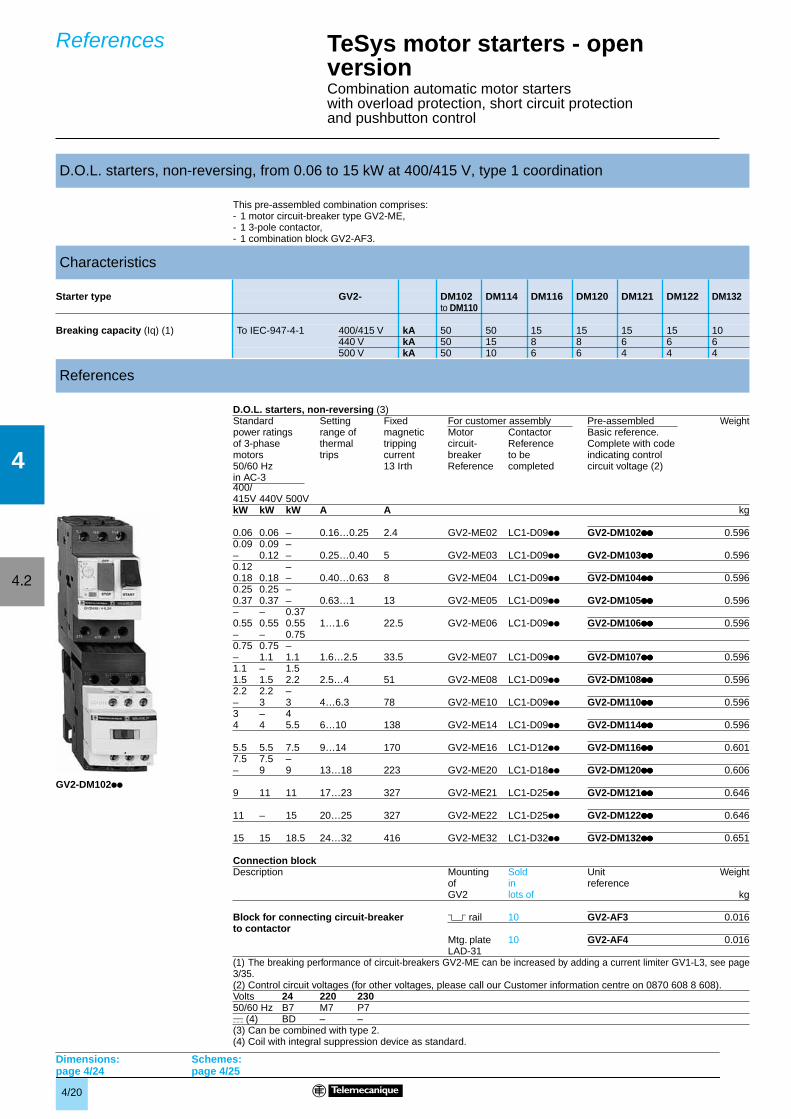
This pre-assembled combination comprises:- 1 motor circuit-breaker type GV2-ME,- 1 3-pole contactor,- 1 combination block GV2-AF3.
D.O.L. starters, non-reversing (3)
400/
(1) The breaking performance of circuit-breakers GV2-ME can be increased by adding a current limiter GV1-L3, see page3/35.(2) Control circuit voltages (for other voltages, please call our Customer information centre on 0870 608 8 608).
(3) Can be combined with type 2.(4) Coil with integral suppression device as standard.
D.O.L. starters, non-reversing, from 0.06 to 15 kW at 400/415 V, type 1 coordination
Characteristics
Starter type GV2- DM102 DM114 DM116 DM120 DM121 DM122 DM132to DM110
Breaking capacity (Iq) (1) To IEC-947-4-1 400/415 V kA 50 50 15 15 15 15 10440 V kA 50 15 8 8 6 6 6500 V kA 50 10 6 6 4 4 4
References
Standard Setting Fixed For customer assembly Pre-assembled Weightpower ratings range of magnetic Motor Contactor Basic reference.of 3-phase thermal tripping circuit- Reference Complete with codemotors trips current breaker to be indicating control50/60 Hz 13 Irth Reference completed circuit voltage (2)in AC-3
415V 440V 500VkW kW kW A A kg
0.06 0.06 – 0.16…0.25 2.4 GV2-ME02 LC1-D09pp GV2-DM102pppppppp 0.5960.09 0.09 –– 0.12 – 0.25…0.40 5 GV2-ME03 LC1-D09pp GV2-DM103pppppppp 0.5960.12 –0.18 0.18 – 0.40…0.63 8 GV2-ME04 LC1-D09pp GV2-DM104pppppppp 0.5960.25 0.25 –0.37 0.37 – 0.63…1 13 GV2-ME05 LC1-D09pp GV2-DM105pppppppp 0.596– – 0.370.55 0.55 0.55 1…1.6 22.5 GV2-ME06 LC1-D09pp GV2-DM106pppppppp 0.596– – 0.750.75 0.75 –– 1.1 1.1 1.6…2.5 33.5 GV2-ME07 LC1-D09pp GV2-DM107pppppppp 0.5961.1 – 1.51.5 1.5 2.2 2.5…4 51 GV2-ME08 LC1-D09pp GV2-DM108pppppppp 0.5962.2 2.2 –– 3 3 4…6.3 78 GV2-ME10 LC1-D09pp GV2-DM110pppppppp 0.5963 – 44 4 5.5 6…10 138 GV2-ME14 LC1-D09pp GV2-DM114pppppppp 0.596
5.5 5.5 7.5 9…14 170 GV2-ME16 LC1-D12pp GV2-DM116pppppppp 0.6017.5 7.5 –– 9 9 13…18 223 GV2-ME20 LC1-D18pp GV2-DM120pppppppp 0.606
9 11 11 17…23 327 GV2-ME21 LC1-D25pp GV2-DM121pppppppp 0.646
11 – 15 20…25 327 GV2-ME22 LC1-D25pp GV2-DM122pppppppp 0.646
15 15 18.5 24…32 416 GV2-ME32 LC1-D32pp GV2-DM132pppppppp 0.651
Connection blockDescription Mounting Sold Unit Weight
of in referenceGV2 lots of kg
Block for connecting circuit-breaker 5 rail 10 GV2-AF3 0.016to contactor
Mtg. plate 10 GV2-AF4 0.016LAD-31
Volts 24 220 23050/60 Hz B7 M7 P7c (4) BD – –
GV2-DM102pp
TeSys motor starters - open versionCombination automatic motor starterswith overload protection, short circuit protectionand pushbutton control
References
Dimensions:page 4/24
Schemes:page 4/25
4/21
4
4.2
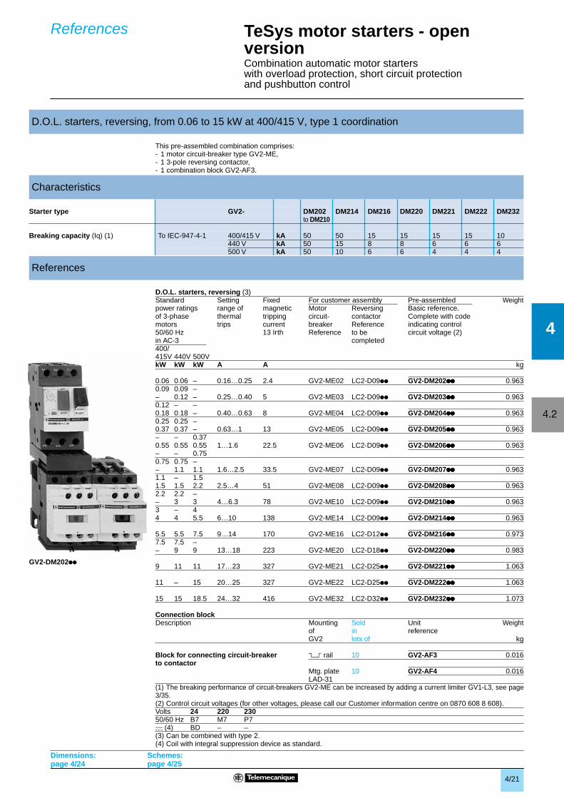
This pre-assembled combination comprises:- 1 motor circuit-breaker type GV2-ME,- 1 3-pole reversing contactor,- 1 combination block GV2-AF3.
D.O.L. starters, reversing (3)
(1) The breaking performance of circuit-breakers GV2-ME can be increased by adding a current limiter GV1-L3, see page3/35.(2) Control circuit voltages (for other voltages, please call our Customer information centre on 0870 608 8 608).
(3) Can be combined with type 2.(4) Coil with integral suppression device as standard.
D.O.L. starters, reversing, from 0.06 to 15 kW at 400/415 V, type 1 coordination
Characteristics
Starter type GV2- DM202 DM214 DM216 DM220 DM221 DM222 DM232to DM210
Breaking capacity (Iq) (1) To IEC-947-4-1 400/415 V kA 50 50 15 15 15 15 10440 V kA 50 15 8 8 6 6 6500 V kA 50 10 6 6 4 4 4
References
Standard Setting Fixed For customer assembly Pre-assembled Weightpower ratings range of magnetic Motor Reversing Basic reference.of 3-phase thermal tripping circuit- contactor Complete with codemotors trips current breaker Reference indicating control50/60 Hz 13 Irth Reference to be circuit voltage (2)in AC-3 completed400/415V 440V 500VkW kW kW A A kg
0.06 0.06 – 0.16…0.25 2.4 GV2-ME02 LC2-D09pp GV2-DM202pppppppp 0.9630.09 0.09 –– 0.12 – 0.25…0.40 5 GV2-ME03 LC2-D09pp GV2-DM203pppppppp 0.9630.12 – –0.18 0.18 – 0.40…0.63 8 GV2-ME04 LC2-D09pp GV2-DM204pppppppp 0.9630.25 0.25 –0.37 0.37 – 0.63…1 13 GV2-ME05 LC2-D09pp GV2-DM205pppppppp 0.963– – 0.370.55 0.55 0.55 1…1.6 22.5 GV2-ME06 LC2-D09pp GV2-DM206pppppppp 0.963– – 0.750.75 0.75 –– 1.1 1.1 1.6…2.5 33.5 GV2-ME07 LC2-D09pp GV2-DM207pppppppp 0.9631.1 – 1.51.5 1.5 2.2 2.5…4 51 GV2-ME08 LC2-D09pp GV2-DM208pppppppp 0.9632.2 2.2 –– 3 3 4…6.3 78 GV2-ME10 LC2-D09pp GV2-DM210pppppppp 0.9633 – 44 4 5.5 6…10 138 GV2-ME14 LC2-D09pp GV2-DM214pppppppp 0.963
5.5 5.5 7.5 9…14 170 GV2-ME16 LC2-D12pp GV2-DM216pppppppp 0.9737.5 7.5 –– 9 9 13…18 223 GV2-ME20 LC2-D18pp GV2-DM220pppppppp 0.983
9 11 11 17…23 327 GV2-ME21 LC2-D25pp GV2-DM221pppppppp 1.063
11 – 15 20…25 327 GV2-ME22 LC2-D25pp GV2-DM222pppppppp 1.063
15 15 18.5 24…32 416 GV2-ME32 LC2-D32pp GV2-DM232pppppppp 1.073
Connection blockDescription Mounting Sold Unit Weight
of in referenceGV2 lots of kg
Block for connecting circuit-breaker 5 rail 10 GV2-AF3 0.016to contactor
Mtg. plate 10 GV2-AF4 0.016LAD-31
Volts 24 220 23050/60 Hz B7 M7 P7c (4) BD – –
GV2-DM202pp
TeSys motor starters - open versionCombination automatic motor starterswith overload protection, short circuit protectionand pushbutton control
References
Dimensions:page 4/24
Schemes:page 4/25
4/22
4
4.2
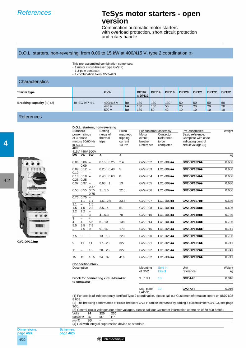
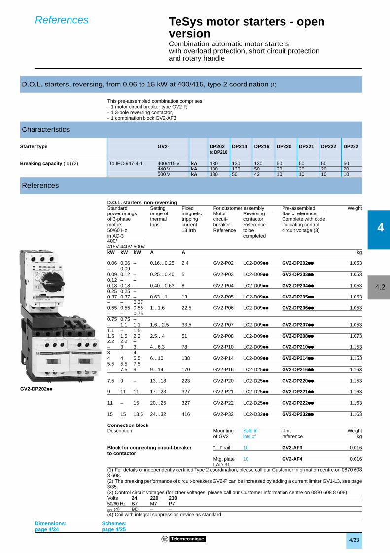
This pre-assembled combination comprises:- 1 motor circuit-breaker type GV2-P,- 1 3-pole contactor,- 1 combination block GV2-AF3
D.O.L. starters, non-reversing
400/
(1) For details of independently certified Type 2 coordination, please call our Customer information centre on 0870 6088 608.(2) The breaking performance of circuit-breakers GV2-P can be increased by adding a current limiter GV1-L3, see page3/35.(3) Control circuit voltages (for other voltages, please call our Customer information centre on 0870 608 8 608).
(4) Coil with integral suppression device as standard.
D.O.L. starters, non-reversing, from 0.06 to 15 kW at 400/415 V, type 2 coordination (1)
Characteristics
Starter type GV2- DP102 DP114 DP116 DP120 DP121 DP122 DP132to DP110
Breaking capacity (Iq) (2) To IEC-947-4-1 400/415 V kA 130 130 130 50 50 50 50440 V kA 130 130 50 20 20 20 20500 V kA 130 50 42 10 10 10 10
References
Standard Setting Fixed For customer assembly Pre-assembled Weightpower ratings range of magnetic Motor Contactor Basic reference.of 3-phase thermal tripping circuit Reference Complete with codemotors 50/60 Hz trips current breaker to be indicating controlin AC-3 13 Irth Reference completed circuit voltage (3)
415V 440V 500VkW kW kW A A kg
0.06 0.06 – 0.16…0.25 2.4 GV2-P02 LC1-D09pp GV2-DP102pppppppp 0.686– 0.090.09 0.12 – 0.25…0.40 5 GV2-P03 LC1-D09pp GV2-DP103pppppppp 0.6860.12 – –0.18 0.18 – 0.40…0.63 8 GV2-P04 LC1-D09pp GV2-DP104pppppppp 0.6860.25 0.25 –0.37 0.37 – 0.63…1 13 GV2-P05 LC1-D09pp GV2-DP105pppppppp 0.686– – 0.370.55 0.55 0.55 1…1.6 22.5 GV2-P06 LC1-D09pp GV2-DP106pppppppp 0.686– – 0.750.75 0.75 –– 1.1 1.1 1.6…2.5 33.5 GV2-P07 LC1-D09pp GV2-DP107pppppppp 0.6861.1 – 1.51.5 1.5 2.2 2.5…4 51 GV2-P08 LC1-D09pp GV2-DP108pppppppp 0.6962.2 2.2 –– 3 3 4…6.3 78 GV2-P10 LC1-D09pp GV2-DP110pppppppp 0.7363 – 44 4 5.5 6…10 138 GV2-P14 LC1-D09pp GV2-DP114pppppppp 0.7365.5 5.5 7.5– 7.5 9 9…14 170 GV2-P16 LC1-D25pp GV2-DP116pppppppp 0.741
7.5 9 – 13…18 223 GV2-P20 LC1-D25pp GV2-DP120pppppppp 0.736
9 11 11 17…23 327 GV2-P21 LC1-D25pp GV2-DP121pppppppp 0.741
11 – 15 20…25 327 GV2-P22 LC1-D25pp GV2-DP122pppppppp 0.741
15 15 18.5 24…32 416 GV2-P32 LC1-D32pp GV2-DP132pppppppp 0.741
Connection blockDescription Mounting Sold in Unit Weight
of GV2 lots of reference kg
Block for connecting circuit-breaker 5 rail 10 GV2-AF3 0.016to contactor
Mtg. plate 10 GV2-AF4 0.016LAD-31
Volts 24 220 23050/60 Hz B7 M7 P7c (4) BD – –
GV2-DP102pppppppp
TeSys motor starters - open versionCombination automatic motor starterswith overload protection, short circuit protectionand rotary handle
References
Dimensions:page 4/24
Schemes:page 4/25
4/23
4
4.2
This pre-assembled combination comprises:- 1 motor circuit-breaker type GV2-P,- 1 3-pole reversing contactor,- 1 combination block GV2-AF3.
D.O.L. starters, non-reversing
400/
(1) For details of independently certified Type 2 coordination, please call our Customer information centre on 0870 6088 608.(2) The breaking performance of circuit-breakers GV2-P can be increased by adding a current limiter GV1-L3, see page3/35.(3) Control circuit voltages (for other voltages, please call our Customer information centre on 0870 608 8 608).
(4) Coil with integral suppression device as standard.
D.O.L. starters, reversing, from 0.06 to 15 kW at 400/415, type 2 coordination (1)
Characteristics
Starter type GV2- DP202 DP214 DP216 DP220 DP221 DP222 DP232to DP210
Breaking capacity (Iq) (2) To IEC-947-4-1 400/415 V kA 130 130 130 50 50 50 50440 V kA 130 130 50 20 20 20 20500 V kA 130 50 42 10 10 10 10
References
Standard Setting Fixed For customer assembly Pre-assembled Weightpower ratings range of magnetic Motor Reversing Basic reference.of 3-phase thermal tripping circuit- contactor Complete with codemotors trips current breaker Reference indicating control50/60 Hz 13 Irth Reference to be circuit voltage (3)in AC-3 completed
415V 440V 500VkW kW kW A A kg
0.06 0.06 – 0.16…0.25 2.4 GV2-P02 LC2-D09pp GV2-DP202pppppppp 1.053– 0.090.09 0.12 – 0.25…0.40 5 GV2-P03 LC2-D09pp GV2-DP203pppppppp 1.0530.12 – –0.18 0.18 – 0.40…0.63 8 GV2-P04 LC2-D09pp GV2-DP204pppppppp 1.0530.25 0.25 –0.37 0.37 – 0.63…1 13 GV2-P05 LC2-D09pp GV2-DP205pppppppp 1.053– – 0.370.55 0.55 0.55 1…1.6 22.5 GV2-P06 LC2-D09pp GV2-DP206pppppppp 1.053– – 0.750.75 0.75 –– 1.1 1.1 1.6…2.5 33.5 GV2-P07 LC2-D09pp GV2-DP207pppppppp 1.0531.1 – 1.51.5 1.5 2.2 2.5…4 51 GV2-P08 LC2-D09pp GV2-DP208pppppppp 1.0732.2 2.2 –– 3 3 4…6.3 78 GV2-P10 LC2-D09pp GV2-DP210pppppppp 1.1533 – 44 4 5.5 6…10 138 GV2-P14 LC2-D09pp GV2-DP214pppppppp 1.1535.5 5.5 7.5– 7.5 9 9…14 170 GV2-P16 LC2-D25pp GV2-DP216pppppppp 1.163
7.5 9 – 13…18 223 GV2-P20 LC2-D25pp GV2-DP220pppppppp 1.153
9 11 11 17…23 327 GV2-P21 LC2-D25pp GV2-DP221pppppppp 1.163
11 – 15 20…25 327 GV2-P22 LC2-D25pp GV2-DP222pppppppp 1.163
15 15 18.5 24…32 416 GV2-P32 LC2-D32pp GV2-DP232pppppppp 1.163
Connection blockDescription Mounting Sold in Unit Weight
of GV2 lots of reference kg
Block for connecting circuit-breaker 5 rail 10 GV2-AF3 0.016to contactor
Mtg. plate 10 GV2-AF4 0.016LAD-31
Volts 24 220 23050/60 Hz B7 M7 P7c (4) BD – –
TeSys motor starters - open versionCombination automatic motor starterswith overload protection, short circuit protectionand rotary handle
References
Dimensions:page 4/24
Schemes:page 4/25
GV2-DP202pp
4/24
4
4.2
45
152
90
b
90
152
66
87
11
c1
c45
b
c1
c
d1
d
c1
c
c1
c
d1
d
45
b
90
b
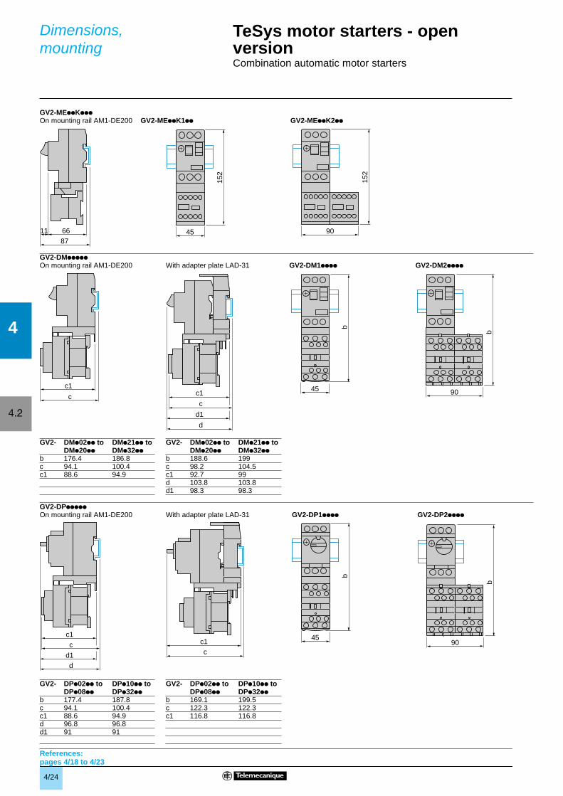
GV2-MEppKppp
GV2-DMppppp
GV2-DPppppp
On mounting rail AM1-DE200 GV2-MEppK1pp GV2-MEppK2pp
On mounting rail AM1-DE200 With adapter plate LAD-31 GV2-DM1pppp GV2-DM2pppp
GV2- DMp02pp to DMp21pp to GV2- DMp02pp to DMp21pp toDMp20pp DMp32pp DMp20pp DMp32pp
b 176.4 186.8 b 188.6 199c 94.1 100.4 c 98.2 104.5c1 88.6 94.9 c1 92.7 99
d 103.8 103.8d1 98.3 98.3
On mounting rail AM1-DE200 With adapter plate LAD-31 GV2-DP1pppp GV2-DP2pppp
GV2- DPp02pp to DPp10pp to GV2- DPp02pp to DPp10pp toDPp08pp DPp32pp DPp08pp DPp32pp
b 177.4 187.8 b 169.1 199.5c 94.1 100.4 c 122.3 122.3c1 88.6 94.9 c1 116.8 116.8d 96.8 96.8d1 91 91
TeSys motor starters - open versionCombination automatic motor starters
Dimensions,mounting
References:pages 4/18 to 4/23
4/25
4
4.2
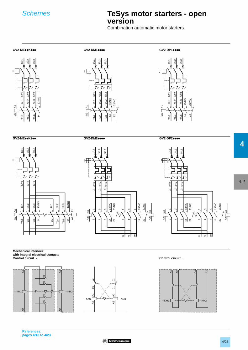
Mechanical interlockwith integral electrical contacts
GV2-MEppK1pp GV2-DM1pppp GV2-DP1pppp
GV2-MEppK2pp GV2-DM2pppp GV2-DP2pppp
Control circuit a Control circuit c
– KM1
A2
A2
0102 02
– KM2
01
A1
A1
– KM1
A1
A2
A1
A2
0101
0202
– KM2
– KM1 – KM2
A1
A2
A2
A1
2/T
1
4/T
2
6/T
3
1/L1
3/L2
5/L3
1/L1
3/L2
5/L3
T1/
2
T2/
4
T3/
6
13/N
O14
A1
A2
2/T
1
4/T
2
6/T
3
1/L1
3/L2
5/L3
14
A1
A2
12
34
56
L1 L2 L3
12
34
56
U V W
13/N
O
1413
/NO
A1
A2
2221
/NC
2221
/NC
2/T
1
4/T
2
6/T
3
1/L1
3/L2
5/L3
14
A1
A2
12
34
56
L1 L2 L3
12
34
56
U V W
13/N
O
1413
/NO
A1
A2
2221
/NC
2221
/NC
2/T
1
4/T
2
6/T
3
1/L1
3/L2
5/L3
1/L1
3/L2
5/L3
T1/
2
T2/
4
T3/
6
13/N
O
T1/
2
T2/
4
T3/
614
13/N
O14
A1
A2
1/L1
3/L2
5/L3
A1
A2
2/T
1
4/T
2
6/T
3
1/L1
3/L2
5/L3
1/L1
3/L2
5/L3
T1/
2
T2/
4
T3/
6
A1
A2
1413
/NO
2221
/NC
2/T
1
4/T
2
6/T
3
1/L1
3/L2
5/L3
1/L1
3/L2
5/L3
T1/
2
T2/
4
T3/
6
A1
A2
1413
/NO
2221
/NC
TeSys motor starters - open versionCombination automatic motor starters
Schemes
References:pages 4/18 to 4/23
4/26
4
4.3
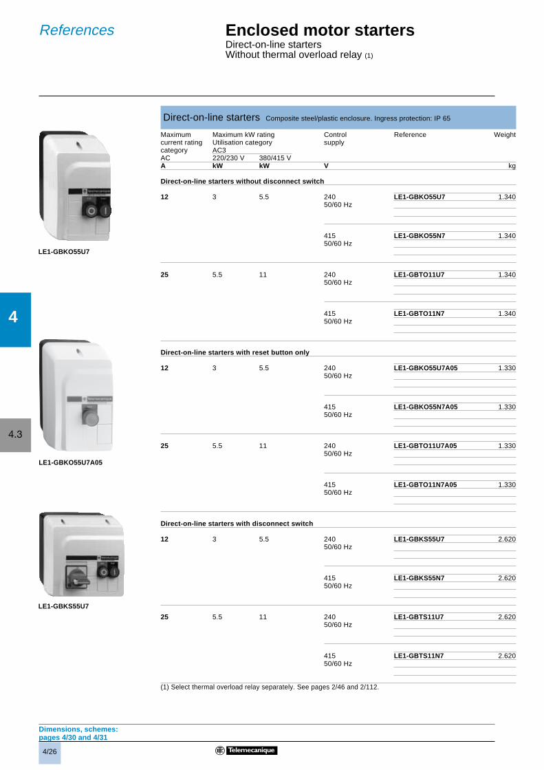
Direct-on-line starters Composite steel/plastic enclosure. Ingress protection: IP 65
Maximum Maximum kW rating Control Reference Weightcurrent rating Utilisation category supplycategory AC3AC 220/230 V 380/415 VA kW kW V kg
Direct-on-line starters without disconnect switch
12 3 5.5 240 LE1-GBKO55U7 1.34050/60 Hz
415 LE1-GBKO55N7 1.34050/60 Hz
25 5.5 11 240 LE1-GBTO11U7 1.34050/60 Hz
415 LE1-GBTO11N7 1.34050/60 Hz
Direct-on-line starters with reset button only
12 3 5.5 240 LE1-GBKO55U7A05 1.33050/60 Hz
415 LE1-GBKO55N7A05 1.33050/60 Hz
25 5.5 11 240 LE1-GBTO11U7A05 1.33050/60 Hz
415 LE1-GBTO11N7A05 1.33050/60 Hz
Direct-on-line starters with disconnect switch
12 3 5.5 240 LE1-GBKS55U7 2.62050/60 Hz
415 LE1-GBKS55N7 2.62050/60 Hz
25 5.5 11 240 LE1-GBTS11U7 2.62050/60 Hz
415 LE1-GBTS11N7 2.62050/60 Hz
(1) Select thermal overload relay separately. See pages 2/46 and 2/112.
Dimensions, schemes:pages 4/30 and 4/31
Enclosed motor startersDirect-on-line startersWithout thermal overload relay (1)
References
LE1-GBKO55U7
LE1-GBKS55U7
LE1-GBKO55U7A05
4/27
4
4.3
Enclosed motor startersDirect-on-line reversing startersWithout thermal overload relay (1)
References
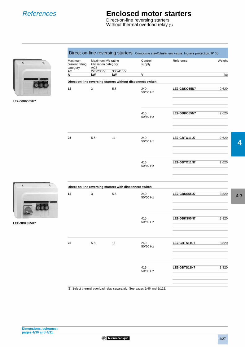
Direct-on-line reversing starters Composite steel/plastic enclosure. Ingress protection: IP 65
Maximum Maximum kW rating Control Reference Weightcurrent rating Utilisation category supplycategory AC3AC 220/230 V 380/415 VA kW kW V kg
Direct-on-line reversing starters without disconnect switch
12 3 5.5 240 LE2-GBKO55U7 2.62050/60 Hz
415 LE2-GBKO55N7 2.62050/60 Hz
25 5.5 11 240 LE2-GBTO11U7 2.62050/60 Hz
415 LE2-GBTO11N7 2.62050/60 Hz
Direct-on-line reversing starters with disconnect switch
12 3 5.5 240 LE2-GBKS55U7 3.82050/60 Hz
415 LE2-GBKS55N7 3.82050/60 Hz
25 5.5 11 240 LE2-GBTS11U7 3.82050/60 Hz
415 LE2-GBTS11N7 3.82050/60 Hz
(1) Select thermal overload relay separately. See pages 2/46 and 2/112.
Dimensions, schemes:pages 4/30 and 4/31
LE2-GBKO55U7
LE2-GBKS55U7
4/28
4
4.3
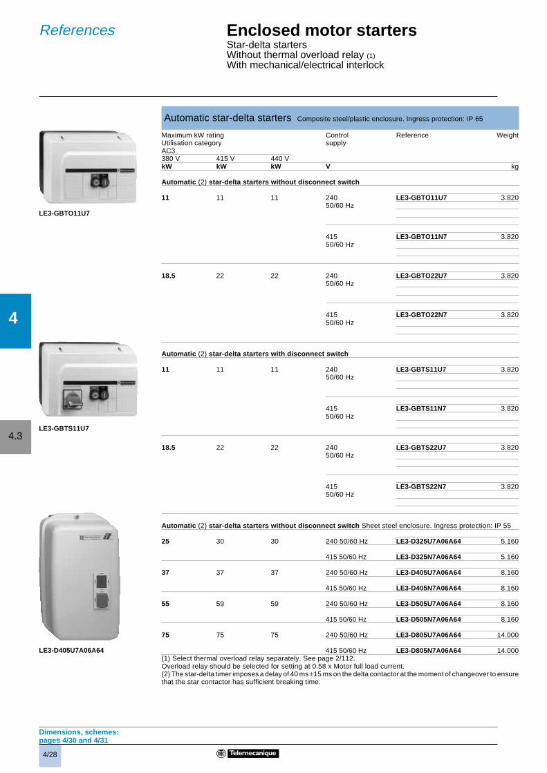
Automatic star-delta starters Composite steel/plastic enclosure. Ingress protection: IP 65
Maximum kW rating Control Reference WeightUtilisation category supplyAC3380 V 415 V 440 VkW kW kW V kg
Automatic (2) star-delta starters without disconnect switch
11 11 11 240 LE3-GBTO11U7 3.82050/60 Hz
415 LE3-GBTO11N7 3.82050/60 Hz
18.5 22 22 240 LE3-GBTO22U7 3.82050/60 Hz
415 LE3-GBTO22N7 3.82050/60 Hz
Automatic (2) star-delta starters with disconnect switch
11 11 11 240 LE3-GBTS11U7 3.82050/60 Hz
415 LE3-GBTS11N7 3.82050/60 Hz
18.5 22 22 240 LE3-GBTS22U7 3.82050/60 Hz
415 LE3-GBTS22N7 3.82050/60 Hz
Automatic (2) star-delta starters without disconnect switch Sheet steel enclosure. Ingress protection: IP 55
25 30 30 240 50/60 Hz LE3-D325U7A06A64 5.160
415 50/60 Hz LE3-D325N7A06A64 5.160
37 37 37 240 50/60 Hz LE3-D405U7A06A64 8.160
415 50/60 Hz LE3-D405N7A06A64 8.160
55 59 59 240 50/60 Hz LE3-D505U7A06A64 8.160
415 50/60 Hz LE3-D505N7A06A64 8.160
75 75 75 240 50/60 Hz LE3-D805U7A06A64 14.000
415 50/60 Hz LE3-D805N7A06A64 14.000(1) Select thermal overload relay separately. See page 2/112.Overload relay should be selected for setting at 0.58 x Motor full load current.(2) The star-delta timer imposes a delay of 40 ms ±15 ms on the delta contactor at the moment of changeover to ensurethat the star contactor has sufficient breaking time.
Dimensions, schemes:pages 4/30 and 4/31
Enclosed motor startersStar-delta startersWithout thermal overload relay (1)
With mechanical/electrical interlock
References
LE3-GBTO11U7
LE3-GBTS11U7
LE3-D405U7A06A64
4/29
4
4.3
Enclosed heating andlighting contactorsEnclosed contactorsWithout thermal overload relayWithout pushbutton controls
References
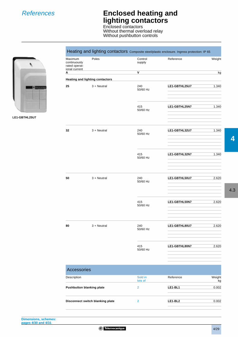
Heating and lighting contactors Composite steel/plastic enclosure. Ingress protection: IP 65
Maximum Poles Control Reference Weightcontinuously supplyrated operat-ional currentA V kg
Heating and lighting contactors
25 3 + Neutral 240 LE1-GBTHL25U7 1.34050/60 Hz
415 LE1-GBTHL25N7 1.34050/60 Hz
32 3 + Neutral 240 LE1-GBTHL32U7 1.34050/60 Hz
415 LE1-GBTHL32N7 1.34050/60 Hz
50 3 + Neutral 240 LE1-GBTHL50U7 2.62050/60 Hz
415 LE1-GBTHL50N7 2.62050/60 Hz
80 3 + Neutral 240 LE1-GBTHL80U7 2.62050/60 Hz
415 LE1-GBTHL80N7 2.62050/60 Hz
Accessories
Description Sold in Reference Weightlots of kg
Pushbutton blanking plate 2 LE1-BL1 0.002
Disconnect switch blanking plate 2 LE1-BL2 0.002
Dimensions, schemes:pages 4/30 and 4/31
LE1-GBTHL25U7
4/30
4
4.3
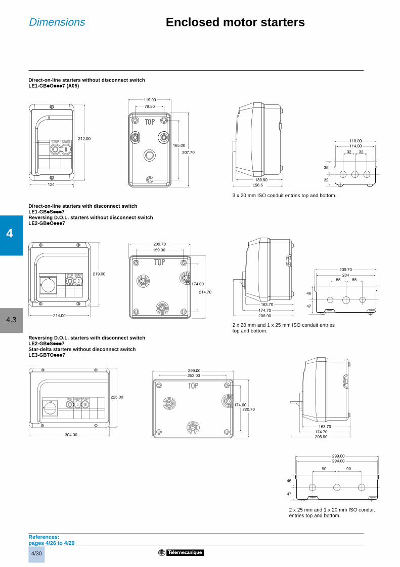
Direct-on-line starters without disconnect switchLE1-GBiOiii7 (A05)
Direct-on-line starters with disconnect switchLE1-GBiSiii7Reversing D.O.L. starters without disconnect switchLE2-GBiOiii7
Reversing D.O.L. starters with disconnect switchLE2-GBiSiii7Star-delta starters without disconnect switchLE3-GBTOiii7
References:pages 4/26 to 4/29
Enclosed motor startersDimensions
119.00114.00
32
35
32
32
119.00
79.50
165.00
207.70
212.00
124
209.70
55
46
47
20455
209.70
159.00
174.00
214.70
219.00
214.00
225.00
304.00
299.00252.00
174.00220.70
299.00294.00
90
46
47
90
174.70206.90
163.70
150.56
139.50
174.70206.90
163.70
3 x 20 mm ISO conduit entries top and bottom.
2 x 20 mm and 1 x 25 mm ISO conduit entriestop and bottom.
2 x 25 mm and 1 x 20 mm ISO conduitentries top and bottom.
156.5
4/31
4
4.3
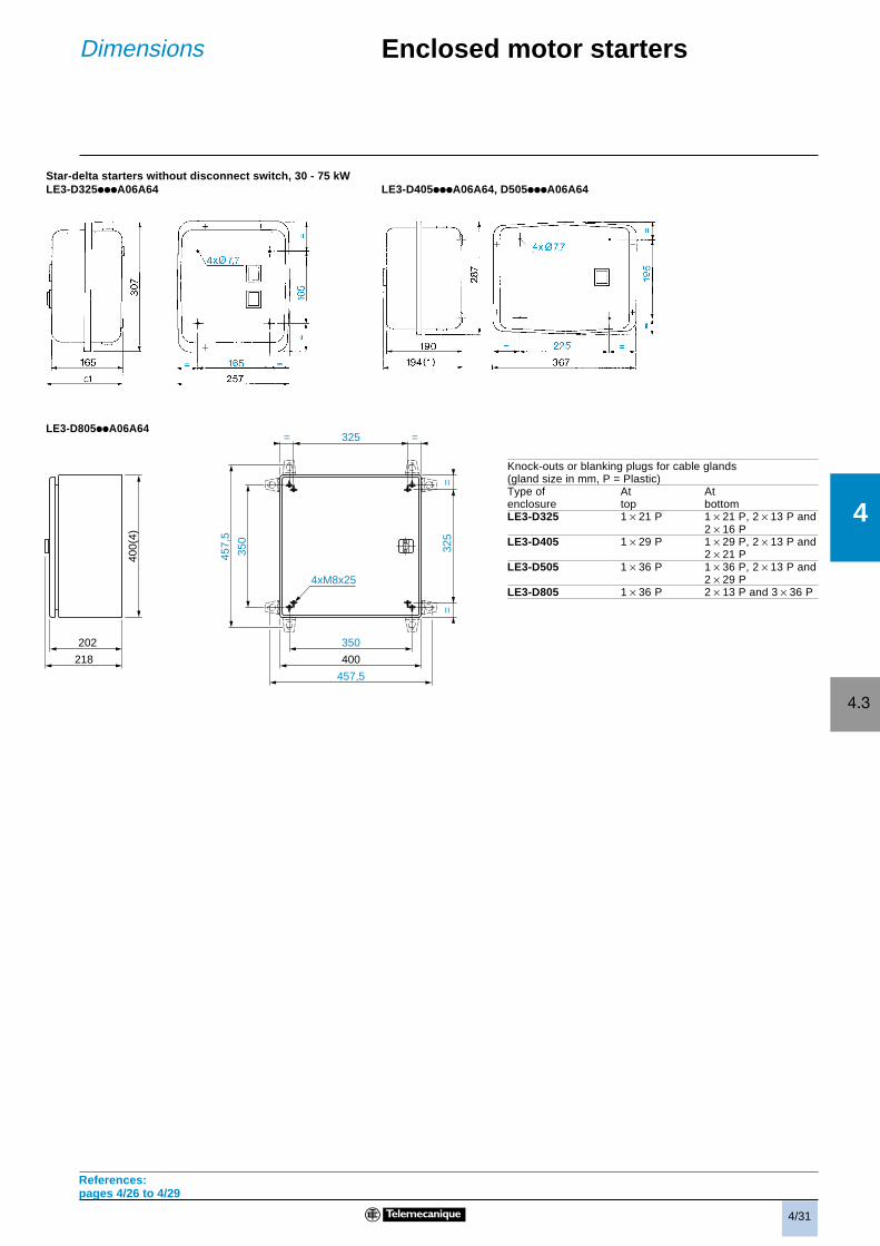
Enclosed motor startersDimensions
Star-delta starters without disconnect switch, 30 - 75 kWLE3-D325iiiA06A64 LE3-D405iiiA06A64, D505iiiA06A64
LE3-D805iiA06A64
Knock-outs or blanking plugs for cable glands(gland size in mm, P = Plastic)Type of At Atenclosure top bottomLE3-D325 1 × 21 P 1 × 21 P, 2 × 13 P and
2 × 16 PLE3-D405 1 × 29 P 1 × 29 P, 2 × 13 P and
2 × 21 PLE3-D505 1 × 36 P 1 × 36 P, 2 × 13 P and
2 × 29 PLE3-D805 1 × 36 P 2 × 13 P and 3 × 36 P
References:pages 4/26 to 4/29
== 325
350
400
457,5
350
457,
5
325
==
400(
4)
202
218
4xM8x25