Embed Size (px)
Citation preview
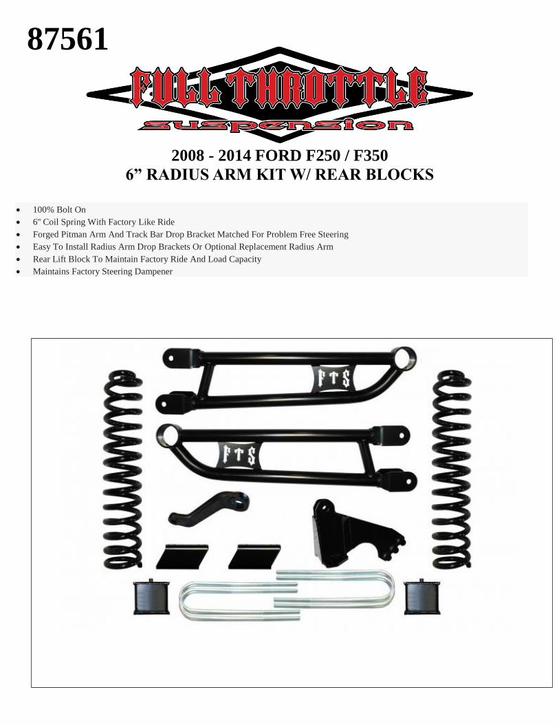
2008 - 2014 FORD F250 / F350
6” RADIUS ARM KIT W/ REAR BLOCKS
100% Bolt On
6'' Coil Spring With Factory Like Ride
Forged Pitman Arm And Track Bar Drop Bracket Matched For Problem Free Steering
Easy To Install Radius Arm Drop Brackets Or Optional Replacement Radius Arm
Rear Lift Block To Maintain Factory Ride And Load Capacity
Maintains Factory Steering Dampener
87561
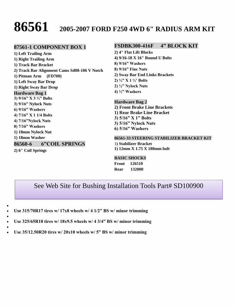
86561 2005-2007 FORD F250 4WD 6" RADIUS ARM KIT
87561-1 COMPONENT BOX 1
1) Left Trailing Arm
1) Right Trailing Arm
1) Track Bar Bracket
2) Track Bar Alignment Cams Sd08-106 V Notch
1) Pitman Arm (FD700)
1) Left Sway Bar Drop
1) Right Sway Bar Drop
Hardware Bag 1 3) 9/16” X 3 ½” Bolts
3) 9/16” Nylock Nuts
6) 9/16” Washers
4) 7/16” X 1 1/4 Bolts
4) 7/16”Nylock Nuts
8) 7/16” Washers
1) 18mm Nylock Nut
1) 18mm Washer
86560-6 6”COIL SPRINGS
2) 6" Coil Springs
Use 315/70R17 tires w/ 17x8 wheels w/ 4 1/2” BS w/ minor trimming
Use 325/65R18 tires w/ 18x9.5 wheels w/ 4 3/4” BS w/ minor trimming
Use 35/12.50R20 tires w/ 20x10 wheels w/ 5” BS w/ minor trimming
See Web Site for Bushing Installation Tools Part# SD100900
FSDBK300-416F 4” BLOCK KIT
2) 4" Flat Lift Blocks
4) 9/16-18 X 16" Round U Bolts
8) 9/16” Washers
8) 9/16” Fine Nuts
2) Sway Bar End Links Brackets
2) ½” X 1 ½’ Bolts
2) ½” Nylock Nuts
4) ½” Washers
Hardware Bag 2
2) Front Brake Line Brackets
1) Rear Brake Line Bracket
3) 5/16” X 1” Bolts
3) 5/16” Nylock Nuts
6) 5/16” Washers
86561-33 STEERING STABILIZER BRACKET KIT
1) Stabilizer Bracket
1) 12mm X 1.75 X 180mm bolt
BASIC SHOCKS
Front 126510
Rear 132000
1) Disconnect the negative terminal on the battery.
Jack up the front end of the truck and support the
frame, at the front frame rails, with jack stands.
NEVER WORK UNDER AN UNSUPPORTED
VEHICLE. Remove the front tires.
2)Working from both sides of the truck, Remove the
brake line and ABS line tabs from the rear side of the
coil spring mount on the axle and follow the line up the
control arm unclipping from the arm and frame save
the hardware.
3) Locate the ABS lines on the radius arms and
disconnect it at its two mounting points. Use care not to
damage the plastic clips on the ABS line as they will be
reused, discard the bolt from the bracket.
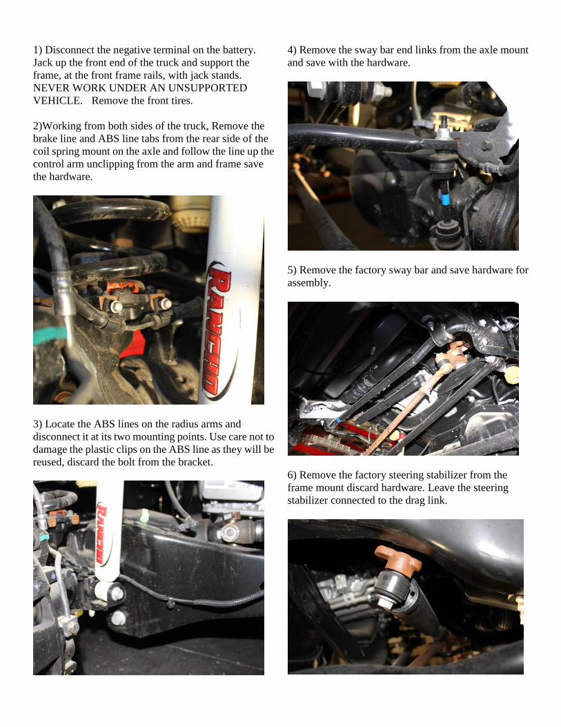
4) Remove the sway bar end links from the axle mount
and save with the hardware.
5) Remove the factory sway bar and save hardware for
assembly.
6) Remove the factory steering stabilizer from the
frame mount discard hardware. Leave the steering
stabilizer connected to the drag link.
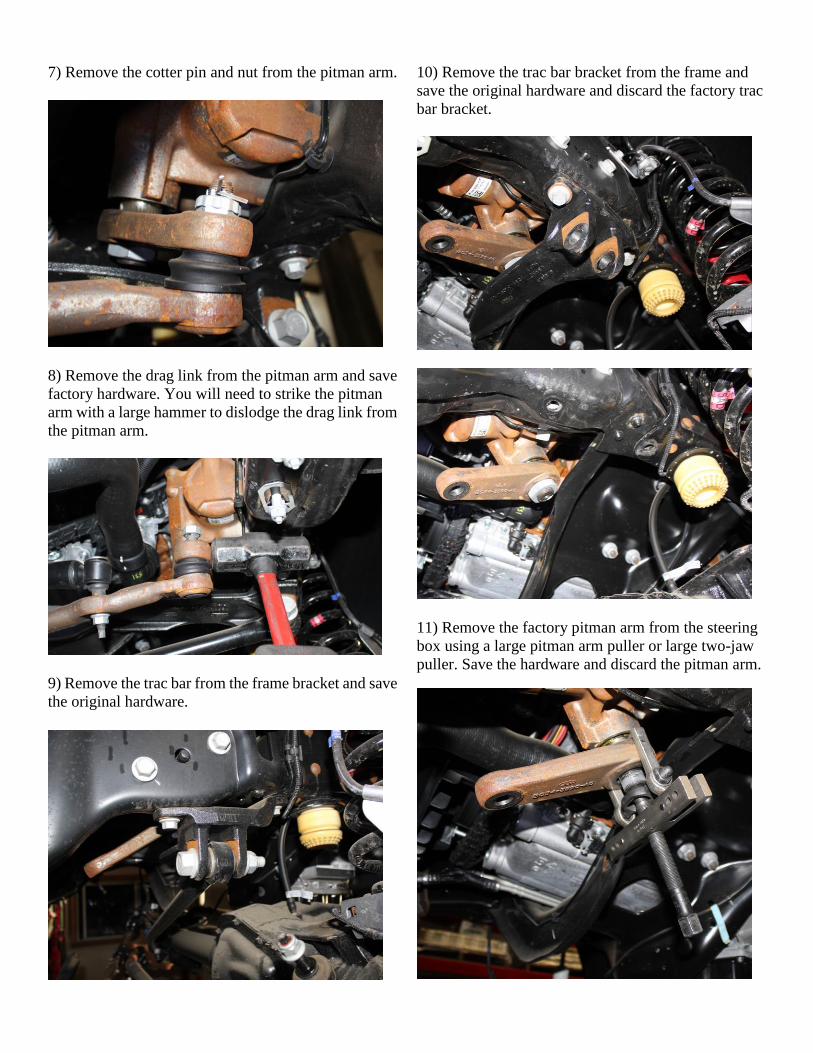
7) Remove the cotter pin and nut from the pitman arm.
8) Remove the drag link from the pitman arm and save
factory hardware. You will need to strike the pitman
arm with a large hammer to dislodge the drag link from
the pitman arm.
9) Remove the trac bar from the frame bracket and save
the original hardware.
10) Remove the trac bar bracket from the frame and
save the original hardware and discard the factory trac
bar bracket.
11) Remove the factory pitman arm from the steering
box using a large pitman arm puller or large two-jaw
puller. Save the hardware and discard the pitman arm.
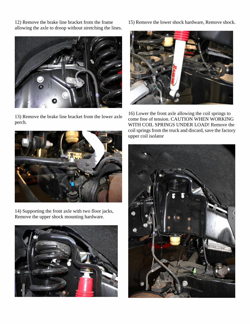
12) Remove the brake line bracket from the frame
allowing the axle to droop without stretching the lines.
13) Remove the brake line bracket from the lower axle
perch.
14) Supporting the front axle with two floor jacks,
Remove the upper shock mounting hardware.
15) Remove the lower shock hardware, Remove shock.
16) Lower the front axle allowing the coil springs to
come free of tension. CAUTION WHEN WORKING
WITH COIL SPRINGS UNDER LOAD! Remove the
coil springs from the truck and discard, save the factory
upper coil isolator
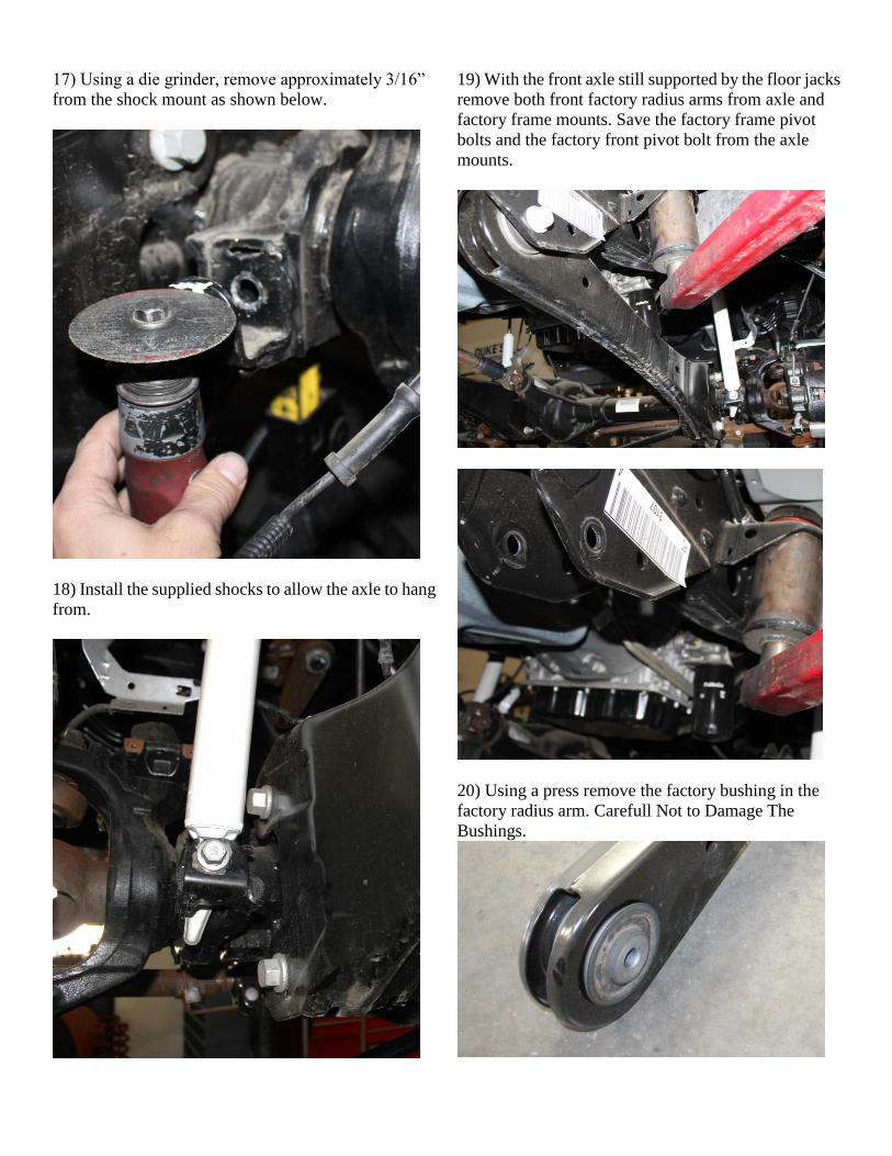
17) Using a die grinder, remove approximately 3/16”
from the shock mount as shown below.
18) Install the supplied shocks to allow the axle to hang
from.
19) With the front axle still supported by the floor jacks
remove both front factory radius arms from axle and
factory frame mounts. Save the factory frame pivot
bolts and the factory front pivot bolt from the axle
mounts.
20) Using a press remove the factory bushing in the
factory radius arm. Carefull Not to Damage The
Bushings.

21) Press the factory bushing into the new FTS radius
arms. Make sure the bushing seat themselves.
22) Working from the passenger side of the truck,
Install passenger side radius arm onto the truck. First
attach the radius arm to the axle mounts using the
factory pivot bolt. then attach the rear pivot to the
frame mount and use the factory bolt. Leave loose at
this time.
23) Repeat step 22 on the driver side of the truck.
24) Install new drop pitman arm. Attach to the steering
box in the same indexed position as the factory pitman
arm was when removed. Torque Sector Shaft Nut to
350 ft. lbs. Use Loctite on the Threads.
25) Install the FTS Trac Bar Frame Bracket. Attach to
the frame using the factory hardware in the same
position. Use the supplied 9/16” x 3 ½’ hardware as
shown below Torque bolts to 110 ft. lbs. DO NOT
ATTACH THE TRAC BAR TO THE FRAME
BRACKET AT THIS TIME.
26) Install the 6” coil springs into the truck in the
factory location using the original factory upper coil
isolator. Make sure that the coil spring is seated
correctly in the upper and lower mounts.
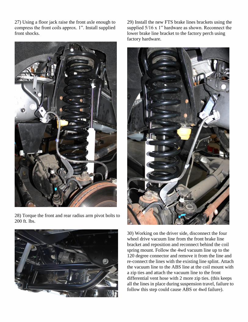
27) Using a floor jack raise the front axle enough to
compress the front coils approx. 1”. Install supplied
front shocks.
28) Torque the front and rear radius arm pivot bolts to
200 ft. lbs.
29) Install the new FTS brake lines brackets using the
supplied 5/16 x 1” hardware as shown. Reconnect the
lower brake line bracket to the factory perch using
factory hardware.
30) Working on the driver side, disconnect the four
wheel drive vacuum line from the front brake line
bracket and reposition and reconnect behind the coil
spring mount. Follow the 4wd vacuum line up to the
120 degree connector and remove it from the line and
re-connect the lines with the existing line splint. Attach
the vacuum line to the ABS line at the coil mount with
a zip ties and attach the vacuum line to the front
differential vent hose with 2 more zip ties. (this keeps
all the lines in place during suspension travel, failure to
follow this step could cause ABS or 4wd failure).
Optional steering stabilizer bracket 31) Install the steering stabilizer drop bracket in the
factory location using the 12mm x 180mm original
hardware. Torque to 50 ft. lbs.
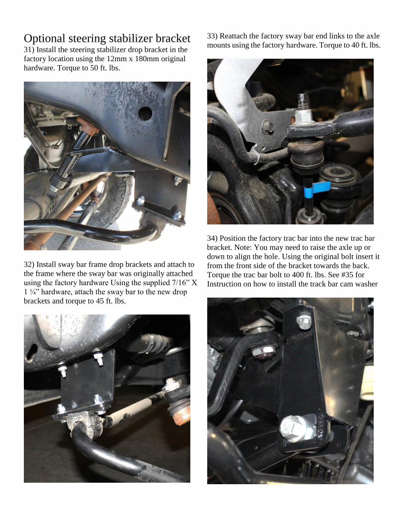
32) Install sway bar frame drop brackets and attach to
the frame where the sway bar was originally attached
using the factory hardware Using the supplied 7/16” X
1 ¼” hardware, attach the sway bar to the new drop
brackets and torque to 45 ft. lbs.
33) Reattach the factory sway bar end links to the axle
mounts using the factory hardware. Torque to 40 ft. lbs.
34) Position the factory trac bar into the new trac bar
bracket. Note: You may need to raise the axle up or
down to align the hole. Using the original bolt insert it
from the front side of the bracket towards the back.
Torque the trac bar bolt to 400 ft. lbs. See #35 for
Instruction on how to install the track bar cam washer
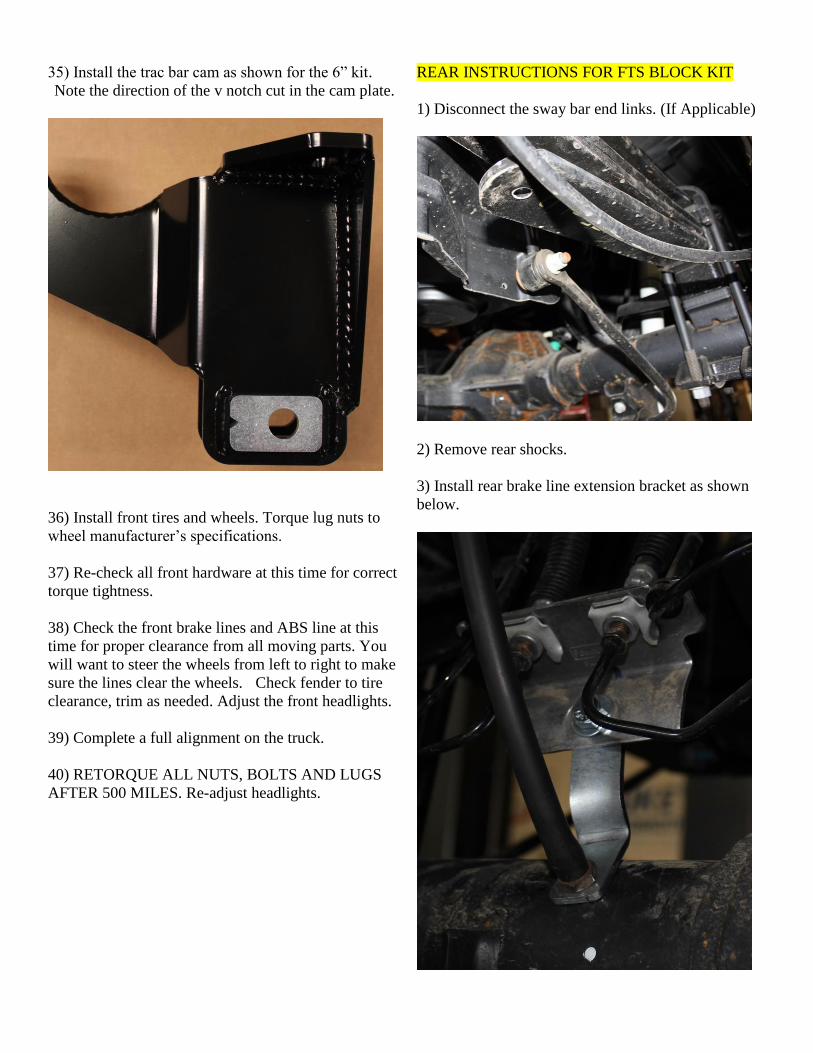
35) Install the trac bar cam as shown for the 6” kit.
Note the direction of the v notch cut in the cam plate.
36) Install front tires and wheels. Torque lug nuts to
wheel manufacturer’s specifications.
37) Re-check all front hardware at this time for correct
torque tightness.
38) Check the front brake lines and ABS line at this
time for proper clearance from all moving parts. You
will want to steer the wheels from left to right to make
sure the lines clear the wheels. Check fender to tire
clearance, trim as needed. Adjust the front headlights.
39) Complete a full alignment on the truck.
40) RETORQUE ALL NUTS, BOLTS AND LUGS
AFTER 500 MILES. Re-adjust headlights.
REAR INSTRUCTIONS FOR FTS BLOCK KIT
1) Disconnect the sway bar end links. (If Applicable)
2) Remove rear shocks.
3) Install rear brake line extension bracket as shown
below.
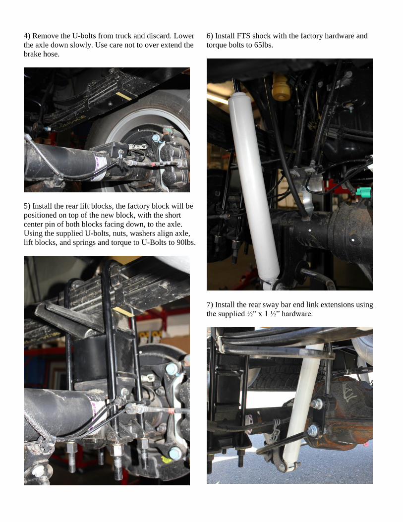
4) Remove the U-bolts from truck and discard. Lower
the axle down slowly. Use care not to over extend the
brake hose.
5) Install the rear lift blocks, the factory block will be
positioned on top of the new block, with the short
center pin of both blocks facing down, to the axle.
Using the supplied U-bolts, nuts, washers align axle,
lift blocks, and springs and torque to U-Bolts to 90lbs.
6) Install FTS shock with the factory hardware and
torque bolts to 65lbs.
7) Install the rear sway bar end link extensions using
the supplied ½” x 1 ½” hardware.

8) Install tires and wheels and torque lug nuts to wheel manufacturer’s specifications.
9) Remove the jack stands and set the truck back onto the ground.
10) Check the torque on all fasteners.
Product Warranty and Warnings- FTS provides a Limited Lifetime Warranty to the original retail purchaser who owns the vehicle, on which the product was originally installed, for defects in
workmanship and materials. The Limited Lifetime Warranty excludes the following FTS items; bushings, bump stops, ball joints, tie rod ends, limiting straps,
cross shafts, heim joints. These parts are subject to wear and are not considered defective when worn. They are warranted for 60 days from the date of purchase
for defects in workmanship.
Reservoir shocks are considered a serviceable shock with a one year warranty on leakage only. Service seal kits are available separately for future maintenance.
All other shocks are covered under our Limited Lifetime Warranty.
FTS does not warrant any product for finish, alterations, modifications and/or installation contrary to FTS instructions. Alterations to the finish of the parts
including but not limited to painting, powder coating, plating and/or welding will void all warranties. Some finish damage may occur to parts during shipping
which is considered normal and is not covered under warranty.
FTS products are not designed nor intended to be installed on vehicles used in race applications or for racing purposes or for similar activities. (A “RACE” is
defined as any contest between two or more vehicles, or any contest of one or more vehicle against the clock, whether or not such contest is for a prize). This
warranty does not include coverage for police or taxi vehicles, race vehicles, or vehicles used for government or commercial purposes. Also excluded from this
warranty are sales outside of the United States of America. Installation of most suspension products will raise the center of gravity of the vehicle and will cause
the vehicle to handle differently than stock. It may increase the vehicle’s susceptibility to a rollover, on road and off road, at all speeds. Extreme care should be
taken to operate the vehicle safely at all times to prevent rollover or loss of control resulting in serious injury or death.
FTS makes every effort to ensure suspension product compatibility with all vehicles listed in the catalog, but due to unknown auto manufacturer’s production
changes and/or inconstancies by the auto manufacturer,
FTS cannot be responsible for 100% compatibility, including the fitment of tire and wheel sizes listed. The Tire and Wheel sizes listed in FTS’s catalog are only
a guideline for street driving with noted fender trimming. FTS is not responsible for damages to the vehicle’s body or tires.
FTS’s obligation under this warranty is limited to the repair or replacement, at FTS option, of the defective product only. All costs of removal, installation or
re-installation, freight charges, incidental or consequential damages are expressly excluded from this warranty. FTS is not responsible for damages and/or
warranty of other vehicle parts related or non-related to the installed FTS product. This warranty is expressly in lieu of all other warranties expressed or implied.
This warranty shall not apply to any product that has been subject to accident, negligence, alteration, abuse or misuse as determined by FTS.
FTS suspension components must be installed as a complete system including shocks as shown on our current website. All warranties will become void if
FTS parts are combined and/or substituted with other aftermarket suspension products. Combination and/or substitution of other aftermarket suspension parts
may cause premature wear and/or product failure resulting in an accident causing injury or death. FTS does not warrant products not manufactured by FTS.
Installation of FTS product may void the vehicles factory warranty; it is the consumer’s responsibility to check with their local vehicle’s dealer for warranty
disposition before the installation of the product.
It is the responsibility of the distributor and/or the retailer to review all warranties and warnings of FTS products with the consumer prior to purchase.
FTS reserves the right to supersede, discontinue, change the design, finish, part number and, or application of parts when deemed necessary without written
notice. FTS is not responsible for misprints or typographical errors within the catalog or price sheet.
Thank You for choosing Full Throttle Suspension Tech support 559-271-8685 or send email to [email protected]


![wellersofguildford.comwellersofguildford.com/content/wp-content/uploads/2017/... · Web viewALONG WTH OTHER BUMPERS [2109] 2023. *2X FORD F250 F350 F450 F550 EXCURSION HEAVY DUTY](https://img.pdfslide.net/doc/110x75/5abc7fa27f8b9ad1768e068f/viewalong-wth-other-bumpers-2109-2023-2x-ford-f250-f350-f450-f550-excursion.jpg)