Embed Size (px)
Citation preview

P5...R30Model: E03
en Assembly and Operating Instructions
Tubular drives for roller shutters
Important information for:
• Fitters / • Electricians / • Users
Please forward accordingly!
These instructions must be kept safe for future reference.
Becker-Antriebe GmbHFriedrich-Ebert-Straße 2-435764 Sinn/Germanywww.becker-antriebe.com

Table of contents
General ............................................................................................................................................................................... 3Warranty ............................................................................................................................................................................. 3Safety instructions ............................................................................................................................................................... 4
Instructions for the user................................................................................................................................................... 4Instructions for installation and commissioning.................................................................................................................. 4
Intended use ....................................................................................................................................................................... 6Drive version with angled plug ............................................................................................................................................... 6Installation........................................................................................................................................................................... 8
Assembling the drive ....................................................................................................................................................... 8Assembling the drive adapter with drive adapter safety catch.............................................................................................. 8Assembling the drive adapter with screw connection.......................................................................................................... 8Securing the drive against axial displacement.................................................................................................................... 9Fixing the drive adapter to the barrel dia. 35 and dia. 45 ..................................................................................................... 9Mounting the drive in the tube .......................................................................................................................................... 9
Setting the limit positions using the programming unit........................................................................................................... 11Deleting the limit positions using the programming unit ......................................................................................................... 13Adjusting the limit positions with a rotary switch or a locking button ........................................................................................ 14Deleting the limit positions with a rotary switch or a locking button ......................................................................................... 16Obstruction detection / Blockage detection ......................................................................................................................... 16Upper anti-freeze mechanism ............................................................................................................................................. 16Information for the electrician ............................................................................................................................................. 17Disposal ............................................................................................................................................................................ 17Maintenance ..................................................................................................................................................................... 17Technical data dia. 35 ........................................................................................................................................................ 17Technical data dia. 45 ........................................................................................................................................................ 18What to do if...?.................................................................................................................................................................. 18Sample wiring diagrams ..................................................................................................................................................... 19Declaration of conformity ................................................................................................................................................... 21
2

GeneralThese tubular drives are high-quality products with the following features:
• Optimised for roller shutter operation
• Automatic detection of limit positions thanks to intelligent electronic system with stop systems
∙ Secure anti-lifting device
∙ Slight pressure applied to the roller shutter curtain makes it difficult to raise or reach under it
∙ Suitable for rigid aluminium, steel and wooden profiles
• Obstruction detection in downwards direction when using suspension springs and anti-lifting device
• Blockage detection in upwards direction (e.g., end strip frozen to the window sill)
• The limit positions do not have to be reset: Changes in the shading solution are accommodated automatically when using stopsystems.
• Drive puts the roller shutter curtain under low tensile load
• Soft upper stop
• Several drives can be operated in parallel
• Compatible with existing drives with electronic limit switching (4-core connecting cable)
• Comprehensive range of the drive manufacturer's control units can be used
Please observe these Assembly and Operating Instructions when installing and setting up the equipment.The date of manufacture comes from the first four digits of the serial number.The numbers 1 and 2 indicate the year and the numbers 3 and 4 indicate the calendar week.Example: 24th calendar week in 2012
Ser. No.: 1224XXXXX
Explanation of pictograms
CAUTION CAUTION indicates a hazardous situation which, if not avoided, couldresult in injury.
ATTENTION ATTENTION indicates measures that must be taken to avoid damage toproperty.
Denotes user tips and other useful information.
WarrantyStructural modifications and incorrect installation which are not in accordance with these and our other instructions can result inserious injuries, e.g., crushing of limbs. Therefore, structural modifications may only be carried out with our prior approval andstrictly in accordance with our instructions, particularly the information contained in these Assembly and Operating Instructions.Any further processing of the products which does not comply with their intended use is not permitted.The end product manufacturer and fitter have to ensure that all the relevant current statutory, official and, in particular, EMC regu-lations are adhered to during utilisation of our products, especially with regard to end product manufacture, installation and cus-tomer advice.
3
Safety instructionsThe following safety instructions and warnings are intended to avert hazards and to prevent property damage and personal injury.
Instructions for the user
General information• All work, including maintenance and cleaning, on electrical installations as well as other system parts
must always be performed by authorised specialists, in particular qualified electricians.
• Children from the age of 8 years and persons with reduced physical, sensory or mental capabilities orlack of experience and/or knowledge may use these devices, provided they are supervised or havebeen instructed in the safe use of the device, and have understood the hazards involved. Children mustnot play with the device.
• Systems have to be checked regularly by authorised specialists for wear and damage.
• Always put damaged systems out of operation immediately until they are repaired by an authorisedspecialist.
• Do not operate equipment if people or objects are within the danger zone.
• Observe the danger zone of the equipment during operation.
• Stop and disconnect the equipment from the mains power supply when maintenance and cleaning isbeing performed either on the system itself or in the immediate vicinity of it.
• Ensure that there is adequate clearance (at least 40 cm) between moving parts and adjacent objects.
CautionSafety instructions for avoiding serious injuries.• Crushing or shearing points must be avoided or protected.
Instructions for installation and commissioning
General information• Observe the safety instructions in EN 60335-2-97. Please note that this list of safety instructions is not
exhaustive, since it would be impossible for the standard to include all sources of danger. For example,the design of the operated product, the way the drive works in the situation it is installed in or even theway the end product is mounted in the end user's place of use cannot be taken into consideration bythe drive manufacturer. If any questions or uncertainties regarding the safety instructions contained in the standard arise,please contact the manufacturer of the part or end product in question.
• All applicable standards and regulations for electrical installation must be complied with.
• All work, including maintenance and cleaning, on electrical installations as well as other system partsmust always be performed by authorised specialists, in particular qualified electricians.
• Only use spare parts, tools and accessory devices which have been approved by the drive manufac-turer. Unapproved third-party products or modifications to the system and its accessories represent a risk toyour safety and the safety of others. This means that the use of unapproved third-party products, ormodifications which have not been agreed with or approved by us, are prohibited. We do not accept li-ability for damage or injury arising from such actions.
• Position control devices within sight of the driven product, but away from moving parts, at a height ofover 1.5 m.
• Permanently mounted control devices must be positioned where they can be seen.
• Rated torque and duty cycle must be suitable for the requirements of the driven product. Technical data – rated torque and service life can be found on the type plate of the tubular drive.
4
• Moving parts of drives must be installed at a height of over 2.5 m above floor level or any other surfacefrom which access to the drive is gained.
• To ensure safe operation of the system after commissioning, the limit positions must be correctly set/programmed in.
• Drives with a H05VV-F connecting cable may only be used indoors.
• Drives with a H05RR-F, S05RN-F or 05RN-F connecting cable may be used both indoors and outdoors.
• To connect the drive to the driven part, solely mechanical accessory components made by the drivemanufacturer from the current product catalogue may be used. The components must be installed inaccordance with the manufacturer's instructions.
• If the drive is used for shading solutions in a specially marked area (e.g., escape routes, hazard zones,safety areas), compliance with all applicable regulations and standards must be ensured.
CautionSafety instructions for avoiding serious injuries.• When electrical or electronic equipment and units are operated, certain components,
e.g., the power supply unit, are live. Physical injuries or damage to property can result inthe event of unauthorised interventions or failure to heed warnings.
• Be careful when touching the tubular drive, as it heats up during operation for technolo-gical reasons.
• Before installation, shut down all lines and control devices that are not essential for op-eration.
• Crushing or shearing points must be avoided or protected.
• When installing the drive, all-pole disconnection from the mains with a contact gap of atleast 3 mm per pole must be provided (EN 60335).
• If the mains connecting cable is damaged, it may only be replaced by the manufacturer.
AttentionSafety instructions for avoiding property damage.• Ensure that there is adequate clearance between moving parts and adjacent objects.
• The drive must not be carried by the mains connecting cable.
• All latching connections and fastening screws on the brackets must be checked to en-sure that they are secure.
• Ensure that nothing rubs against the tubular drive, such as shading solution attach-ments, screws, etc.
5
Intended useThe type of tubular drive described in these instructions is intended solely for the operation of roller shutters.This type of tubular drive supports not only curtain attachment by means of springs but also mechanical anti-lifting devices (e.g.,Zurfluh-Feller, Simu, GAH Alberts and Deprat). These are detected automatically.When mounting connection parts on the drive PXX/XX dia. 35 mm, only use screws EJOT Delta PT 40x12 WN 5454 Torx(9900 000 545 4).For sun protection applications, please use only the types of tubular drive designed for this purpose.This type of tubular drive is designed for use in single systems (one drive per barrel).The tubular drive must not be used in potentially explosive areas.The connecting cable is not suitable for transporting the drive. Always carry the drive by the housing tube.Other applications, uses and modifications are not permitted in order to protect the safety of the users and others, since these ac-tions can impair the system’s safety and carry the risk of personal injury and property damage. The drive manufacturer does notaccept liability for damages or injury arising from such actions.Always observe the information in these instructions when operating or repairing the system. The drive manufacturer does not ac-cept liability for damage or injury resulting from improper usage.
AttentionOnly use anti-lifting devices if the roller shutter laths are sufficiently strong. The closedcurtain must not project beyond the guide tracks or else there is a risk of the joint betweenthe top two laths being subjected to excessive strain and getting damaged.
Drive version with angled plug
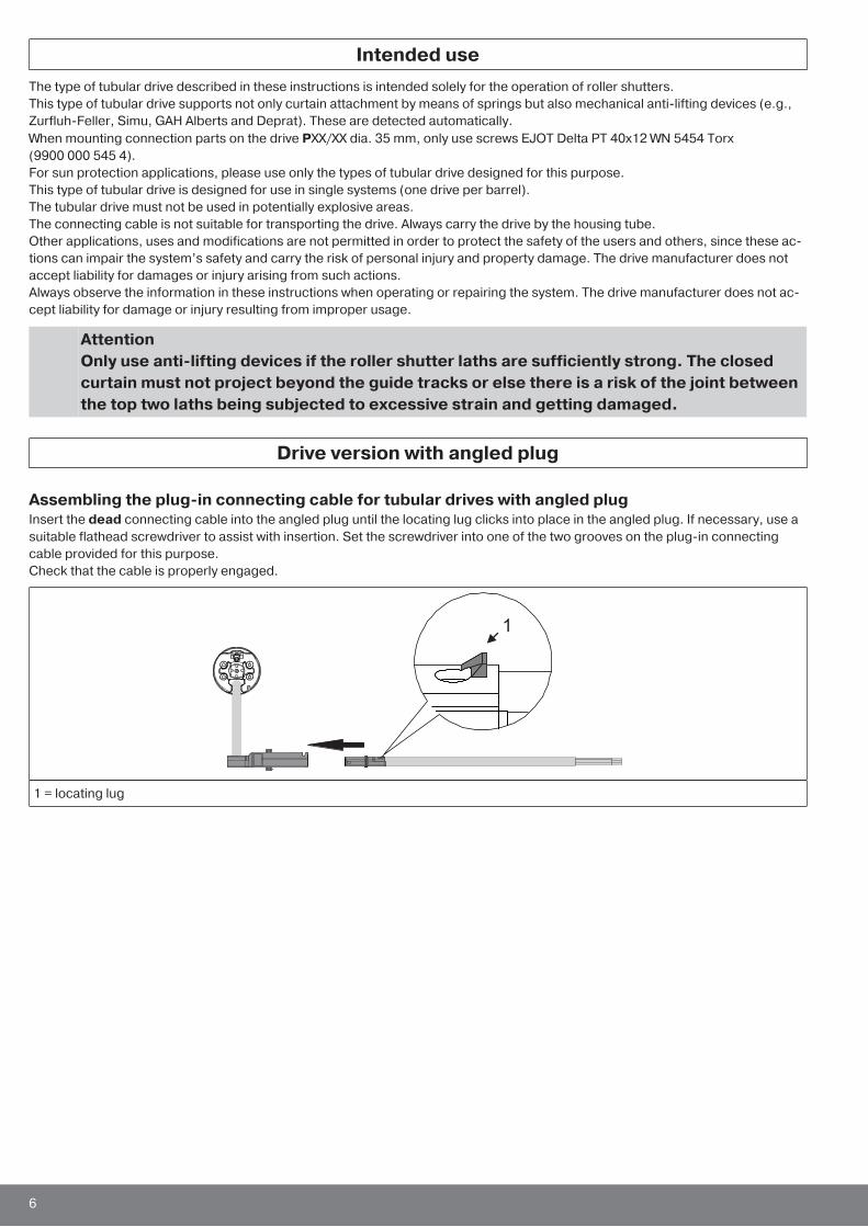
Assembling the plug-in connecting cable for tubular drives with angled plugInsert the dead connecting cable into the angled plug until the locating lug clicks into place in the angled plug. If necessary, use asuitable flathead screwdriver to assist with insertion. Set the screwdriver into one of the two grooves on the plug-in connectingcable provided for this purpose.Check that the cable is properly engaged.
1
1 = locating lug
6
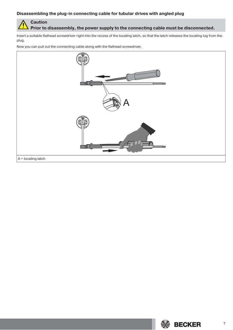
Disassembling the plug-in connecting cable for tubular drives with angled plug
CautionPrior to disassembly, the power supply to the connecting cable must be disconnected.
Insert a suitable flathead screwdriver right into the recess of the locating latch, so that the latch releases the locating lug from theplug.
Now you can pull out the connecting cable along with the flathead screwdriver.
A
A = locating latch
7
Installation
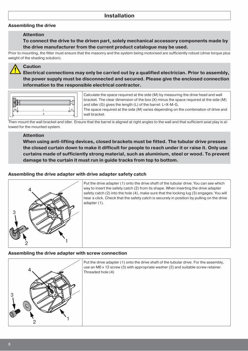
Assembling the drive
AttentionTo connect the drive to the driven part, solely mechanical accessory components made bythe drive manufacturer from the current product catalogue may be used.
Prior to mounting, the fitter must ensure that the masonry and the system being motorised are sufficiently robust (drive torque plusweight of the shading solution).
CautionElectrical connections may only be carried out by a qualified electrician. Prior to assembly,the power supply must be disconnected and secured. Please give the enclosed connectioninformation to the responsible electrical contractor.
Calculate the space required at the side (M) by measuring the drive head and wallbracket. The clear dimension of the box (X) minus the space required at the side (M)and idler (G) gives the length (L) of the barrel: L=X-M-G.The space required at the side (M) varies depending on the combination of drive andwall bracket.
Then mount the wall bracket and idler. Ensure that the barrel is aligned at right angles to the wall and that sufficient axial play is al-lowed for the mounted system.
AttentionWhen using anti-lifting devices, closed brackets must be fitted. The tubular drive pressesthe closed curtain down to make it difficult for people to reach under it or raise it. Only usecurtains made of sufficiently strong material, such as aluminium, steel or wood. To preventdamage to the curtain it must run in guide tracks from top to bottom.
Assembling the drive adapter with drive adapter safety catch
Put the drive adapter (1) onto the drive shaft of the tubular drive. You can see whichway to insert the safety catch (2) from its shape. When inserting the drive adaptersafety catch (2) into the hole (4), make sure that the locking lug (3) engages. You willhear a click. Check that the safety catch is securely in position by pulling on the driveadapter (1).
Assembling the drive adapter with screw connection
Put the drive adapter (1) onto the drive shaft of the tubular drive. For the assembly,use an M6 x 12 screw (3) with appropriate washer (2) and suitable screw retainer.Threaded hole (4)
8
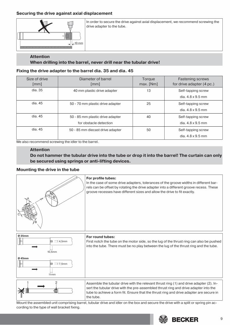
Securing the drive against axial displacement
-10 mm
In order to secure the drive against axial displacement, we recommend screwing thedrive adapter to the tube.
AttentionWhen drilling into the barrel, never drill near the tubular drive!
Fixing the drive adapter to the barrel dia. 35 and dia. 45
Size of drive[mm]
Diameter of barrel[mm]
Torquemax. [Nm]
Fastening screwsfor drive adapter (4 pc.)
dia. 35 40 mm plastic drive adapter 13 Self-tapping screw
dia. 4.8 x 9.5 mm
dia. 45 50 - 70 mm plastic drive adapter 25 Self-tapping screw
dia. 4.8 x 9.5 mm
dia. 45 50 - 85 mm plastic drive adapter
for obstacle detection
40 Self-tapping screw
dia. 4.8 x 9.5 mm
dia. 45 50 - 85 mm diecast drive adapter 50 Self-tapping screw
dia. 4.8 x 9.5 mm
We also recommend screwing the idler to the barrel.
AttentionDo not hammer the tubular drive into the tube or drop it into the barrel! The curtain can onlybe secured using springs or anti-lifting devices.
Mounting the drive in the tube
For profile tubes:In the case of some drive adapters, tolerances of the groove widths in different bar-rels can be offset by rotating the drive adapter into a different groove recess. Thesegroove recesses have different sizes and allow the drive to fit exactly.
For round tubes:First notch the tube on the motor side, so the lug of the thrust ring can also be pushedinto the tube. There must be no play between the lug of the thrust ring and the tube.
Assemble the tubular drive with the relevant thrust ring (1) and drive adapter (2). In-sert the tubular drive with the pre-assembled thrust ring and drive adapter into thetube to achieve a form fit. Ensure that the thrust ring and drive adapter are secure inthe tube.
Mount the assembled unit comprising barrel, tubular drive and idler on the box and secure the drive with a split or spring pin ac-cording to the type of wall bracket fixing.
9

Automatic setting of limit positions is possible, where a stop system is present onboth sides, using the switch (Item no. 4901 001 158 0), a standard rotary switch orthe programming unit for drives with electronic limit switching (Item no.4935 200 011 0). All other functions can only be set via the programming unit.Connect the wires of the tubular drive to those of the same colour in the program-ming/operator control and switch on the power supply.
Position the barrel so that the roller shutter curtain can be attached with springs or fit the anti-lifting devices in accordance with themanufacturer's instructions.
AttentionThe switch and the programming unit are only meant for the commissioning, not for con-tinuous operation!
When employing springs/anti-lifting devices, we recommend the use of at least three; forlonger tubes, use three springs/anti-lifting devices per metre of barrel.
Lay the connecting cableLay the connecting cable up to the tubular drive, and fix The connecting cable andany antennae must not project into the winding chamber. Cover any sharp edges.
10
Setting the limit positions using the programming unit
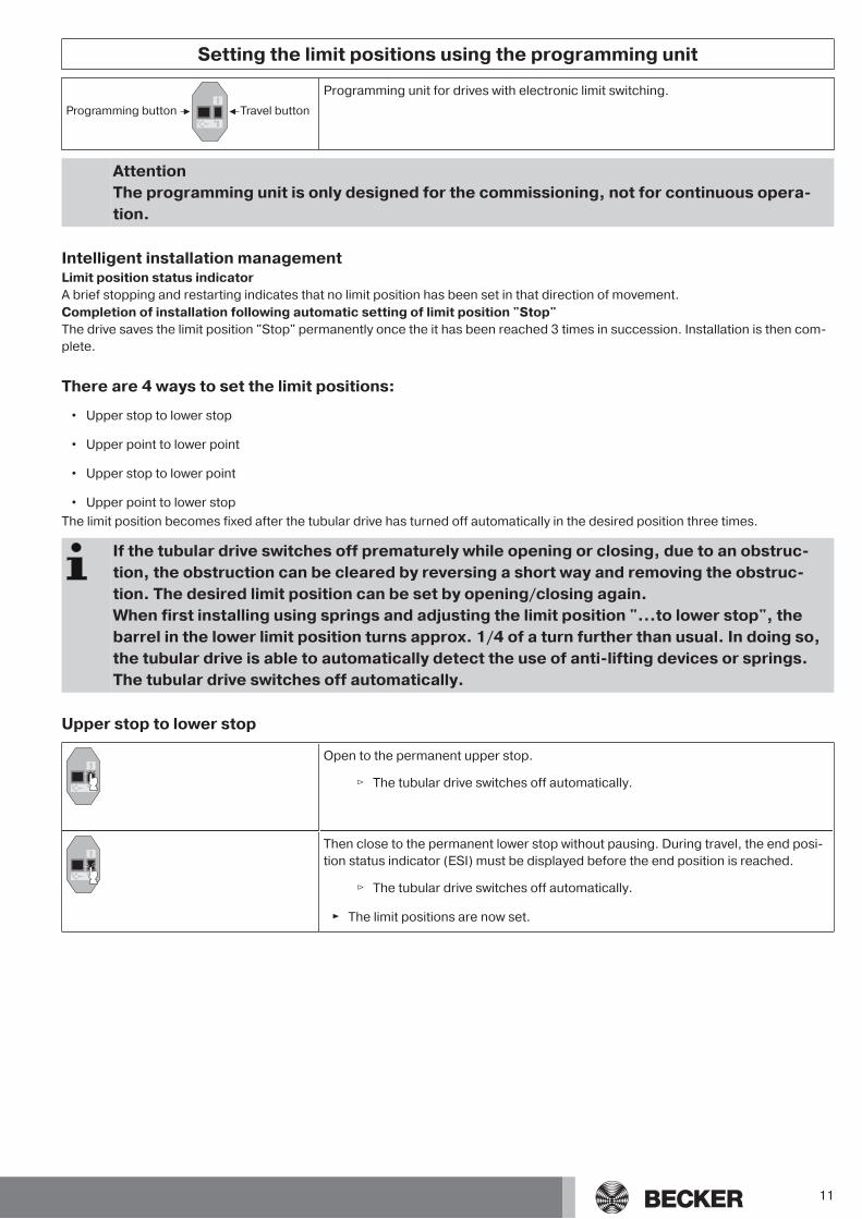
Programming button Travel button
Programming unit for drives with electronic limit switching.
AttentionThe programming unit is only designed for the commissioning, not for continuous opera-tion.
Intelligent installation managementLimit position status indicatorA brief stopping and restarting indicates that no limit position has been set in that direction of movement.Completion of installation following automatic setting of limit position "Stop"The drive saves the limit position "Stop" permanently once the it has been reached 3 times in succession. Installation is then com-plete.
There are 4 ways to set the limit positions:
• Upper stop to lower stop
• Upper point to lower point
• Upper stop to lower point
• Upper point to lower stopThe limit position becomes fixed after the tubular drive has turned off automatically in the desired position three times.
If the tubular drive switches off prematurely while opening or closing, due to an obstruc-tion, the obstruction can be cleared by reversing a short way and removing the obstruc-tion. The desired limit position can be set by opening/closing again.When first installing using springs and adjusting the limit position "...to lower stop", thebarrel in the lower limit position turns approx. 1/4 of a turn further than usual. In doing so,the tubular drive is able to automatically detect the use of anti-lifting devices or springs.The tubular drive switches off automatically.
Upper stop to lower stop
Open to the permanent upper stop.
▻ The tubular drive switches off automatically.
Then close to the permanent lower stop without pausing. During travel, the end posi-tion status indicator (ESI) must be displayed before the end position is reached.
▻ The tubular drive switches off automatically.
► The limit positions are now set.
11
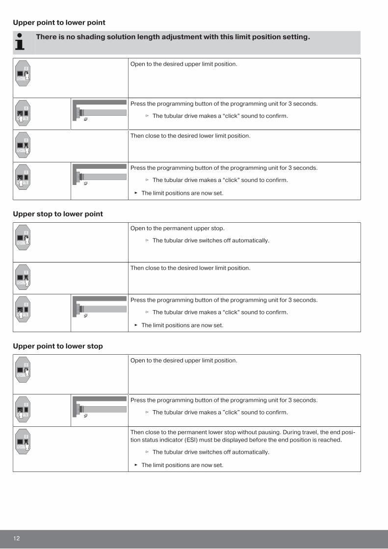
Upper point to lower point
There is no shading solution length adjustment with this limit position setting.
Open to the desired upper limit position.
Press the programming button of the programming unit for 3 seconds.
▻ The tubular drive makes a “click” sound to confirm.
Then close to the desired lower limit position.
Press the programming button of the programming unit for 3 seconds.
▻ The tubular drive makes a “click” sound to confirm.
► The limit positions are now set.
Upper stop to lower point
Open to the permanent upper stop.
▻ The tubular drive switches off automatically.
Then close to the desired lower limit position.
Press the programming button of the programming unit for 3 seconds.
▻ The tubular drive makes a “click” sound to confirm.
► The limit positions are now set.
Upper point to lower stop
Open to the desired upper limit position.
Press the programming button of the programming unit for 3 seconds.
▻ The tubular drive makes a "click" sound to confirm.
Then close to the permanent lower stop without pausing. During travel, the end posi-tion status indicator (ESI) must be displayed before the end position is reached.
▻ The tubular drive switches off automatically.
► The limit positions are now set.
12
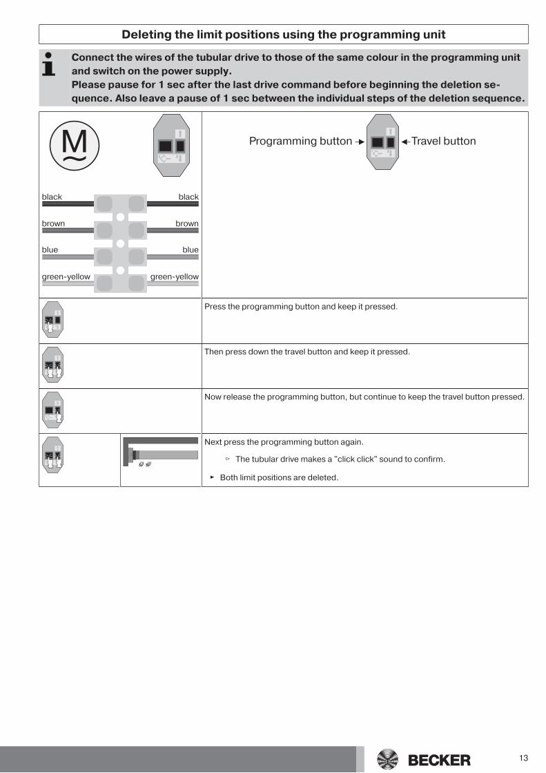
Deleting the limit positions using the programming unit
Connect the wires of the tubular drive to those of the same colour in the programming unitand switch on the power supply.Please pause for 1 sec after the last drive command before beginning the deletion se-quence. Also leave a pause of 1 sec between the individual steps of the deletion sequence.
black
brown
blue
green-yellow
black
brown
blue
green-yellow
Programming button Travel button
Press the programming button and keep it pressed.
Then press down the travel button and keep it pressed.
Now release the programming button, but continue to keep the travel button pressed.
Next press the programming button again.
▻ The tubular drive makes a "click click" sound to confirm.
► Both limit positions are deleted.
13
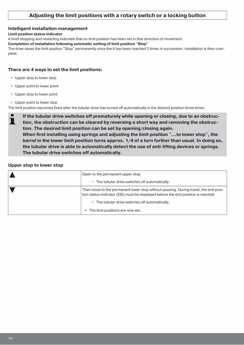
Adjusting the limit positions with a rotary switch or a locking button
Intelligent installation managementLimit position status indicatorA brief stopping and restarting indicates that no limit position has been set in that direction of movement.Completion of installation following automatic setting of limit position "Stop"The drive saves the limit position "Stop" permanently once the it has been reached 3 times in succession. Installation is then com-plete.
There are 4 ways to set the limit positions:
• Upper stop to lower stop
• Upper point to lower point
• Upper stop to lower point
• Upper point to lower stopThe limit position becomes fixed after the tubular drive has turned off automatically in the desired position three times.
If the tubular drive switches off prematurely while opening or closing, due to an obstruc-tion, the obstruction can be cleared by reversing a short way and removing the obstruc-tion. The desired limit position can be set by opening/closing again.When first installing using springs and adjusting the limit position "...to lower stop", thebarrel in the lower limit position turns approx. 1/4 of a turn further than usual. In doing so,the tubular drive is able to automatically detect the use of anti-lifting devices or springs.The tubular drive switches off automatically.
Upper stop to lower stop
Open to the permanent upper stop.
▻ The tubular drive switches off automatically.
Then close to the permanent lower stop without pausing. During travel, the end posi-tion status indicator (ESI) must be displayed before the end position is reached.
▻ The tubular drive switches off automatically.
► The limit positions are now set.
14
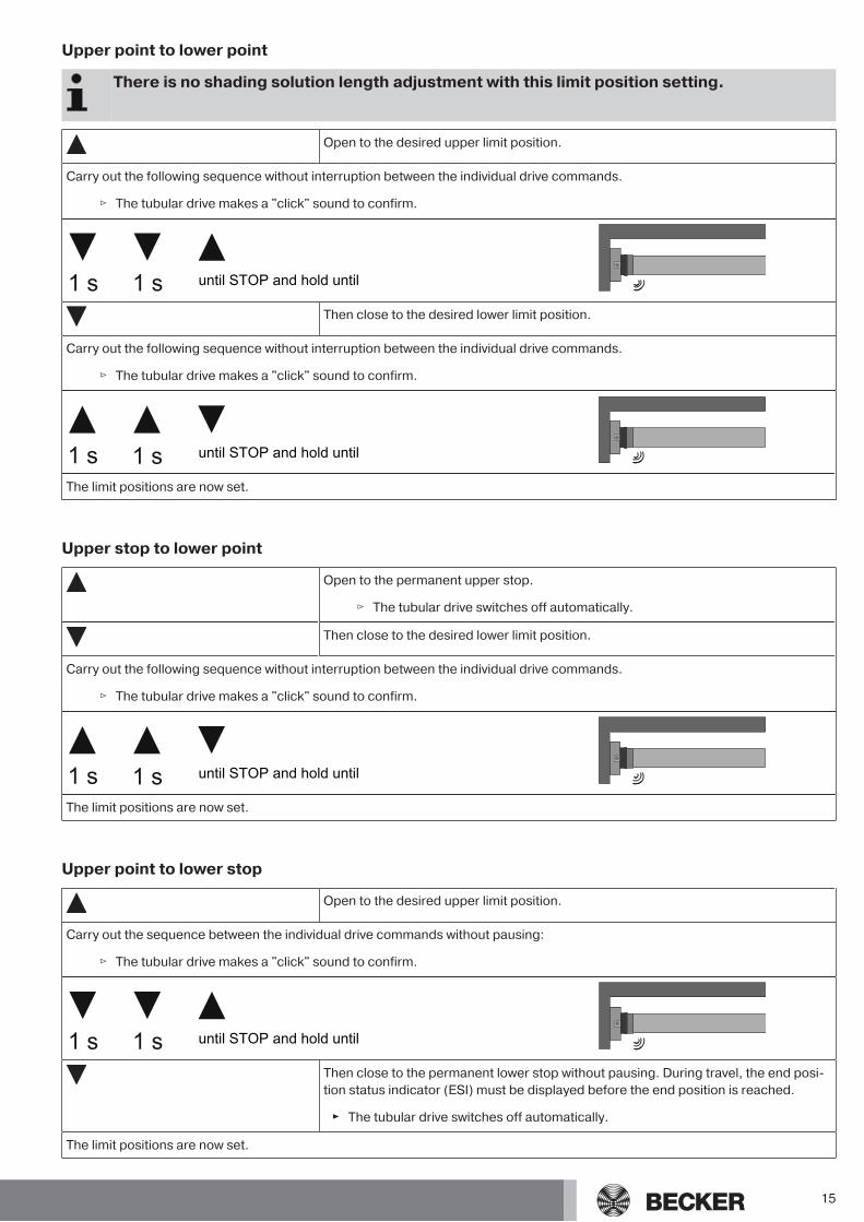
Upper point to lower point
There is no shading solution length adjustment with this limit position setting.
Open to the desired upper limit position.
Carry out the following sequence without interruption between the individual drive commands.
▻ The tubular drive makes a "click" sound to confirm.
1 s 1 s until STOP and hold until
Then close to the desired lower limit position.
Carry out the following sequence without interruption between the individual drive commands.
▻ The tubular drive makes a "click" sound to confirm.
1 s 1 s until STOP and hold until
The limit positions are now set.
Upper stop to lower point
Open to the permanent upper stop.
▻ The tubular drive switches off automatically.
Then close to the desired lower limit position.
Carry out the following sequence without interruption between the individual drive commands.
▻ The tubular drive makes a "click" sound to confirm.
1 s 1 s until STOP and hold until
The limit positions are now set.
Upper point to lower stop
Open to the desired upper limit position.
Carry out the sequence between the individual drive commands without pausing:
▻ The tubular drive makes a "click" sound to confirm.
1 s 1 s until STOP and hold until
Then close to the permanent lower stop without pausing. During travel, the end posi-tion status indicator (ESI) must be displayed before the end position is reached.
► The tubular drive switches off automatically.
The limit positions are now set.
15
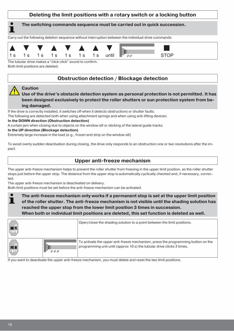
Deleting the limit positions with a rotary switch or a locking button
The switching commands sequence must be carried out in quick succession.
Carry out the following deletion sequence without interruption between the individual drive commands:
STOP1 s until1 s 1 s 1 s 1 s 1 s 1 s
The tubular drive makes a “click click” sound to confirm.Both limit positions are deleted.
Obstruction detection / Blockage detection
CautionUse of the drive’s obstacle detection system as personal protection is not permitted. It hasbeen designed exclusively to protect the roller shutters or sun protection system from be-ing damaged.
If the drive is correctly installed, it switches off when it detects obstructions or shutter faults.The following are detected both when using attachment springs and when using anti-lifting devices:In the DOWN direction (Obstruction detection)A curtain jam when closing due to objects on the window sill or sticking of the lateral guide tracks.In the UP direction (Blockage detection)Extremely large increase in the load (e.g., frozen end strip on the window sill)
To avoid overly sudden deactivation during closing, the drive only responds to an obstruction one or two revolutions after the im-pact.
Upper anti-freeze mechanismThe upper anti-freeze mechanism helps to prevent the roller shutter from freezing in the upper limit position, as the roller shutterstops just before the upper stop. The distance from the upper stop is automatically cyclically checked and, if necessary, correc-ted.The upper anti-freeze mechanism is deactivated on delivery.Both limit positions must be set before the anti-freeze mechanism can be activated.
The anti-freeze mechanism only works if a permanent stop is set at the upper limit positionof the roller shutter. The anti-freeze mechanism is not visible until the shading solution hasreached the upper stop from the lower limit position 3 times in succession.When both or individual limit positions are deleted, this set function is deleted as well.
Open/close the shading solution to a point between the limit positions.
To activate the upper anti-freeze mechanism, press the programming button on theprogramming unit until (approx 10 s) the tubular drive clicks 3 times.
If you want to deactivate the upper anti-freeze mechanism, you must delete and reset the two limit positions.
16
Information for the electricianTubular drives with electronic limit switching can be connected in parallel. The maximum switching contact load of the switchingequipment (timer, relay control, switch, etc.) must be observed. To operate drives with electronic limit switching, only use switch-ing elements (timers) that are not earthed via the drive. The outputs of the switching element must be potential-free in the neutralposition.Use external conductor L1 to control the up and down direction. Other devices or consumers (lamps, relays, etc.) must not be dir-ectly connected to the drive connecting cables. For this purpose, the drives and additional devices must be decoupled by relaycontrols.When installing the drive, all-pole disconnection from the mains with a contact gap of at least 3 mm per pole must be provided (EN60335).
AttentionOnly use mechanically or electrically locked switching elements with a marked zero posi-tion! This also applies when drives with electronic and mechanical limit switching are usedin the same system. The changeover time for switching the running direction must be atleast 0.5 s. The switch and control must not execute simultaneous UP and DOWN com-mands. Protect the electrical connections from damp.Once you have finished wiring everything to the control, ALWAYS check the right directionassignment of the drive to the control buttons UP and DOWN, EXTEND and RETRACT.If the drive is to be operated with devices which contain sources of interference, the elec-trician must ensure suitable interference suppression for the relevant devices.
DisposalThis product is made of various materials which must be disposed of properly. Find out about the applicable regulations on recyc-ling or disposal for this product in your country.The packaging material must be disposed of properly.
MaintenanceThese drives are maintenance-free.
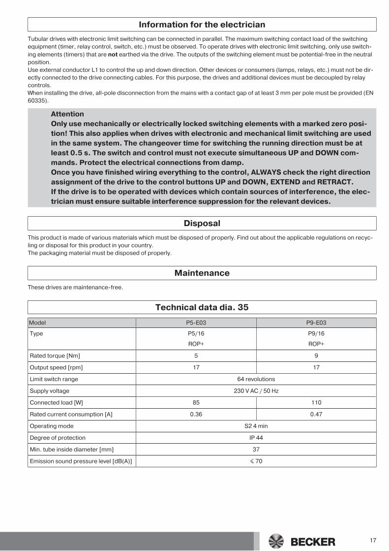
Technical data dia. 35
Model P5-E03 P9-E03
Type P5/16
ROP+
P9/16
ROP+
Rated torque [Nm] 5 9
Output speed [rpm] 17 17
Limit switch range 64 revolutions
Supply voltage 230 V AC / 50 Hz
Connected load [W] 85 110
Rated current consumption [A] 0.36 0.47
Operating mode S2 4 min
Degree of protection IP 44
Min. tube inside diameter [mm] 37
Emission sound pressure level [dB(A)] ≤ 70
17
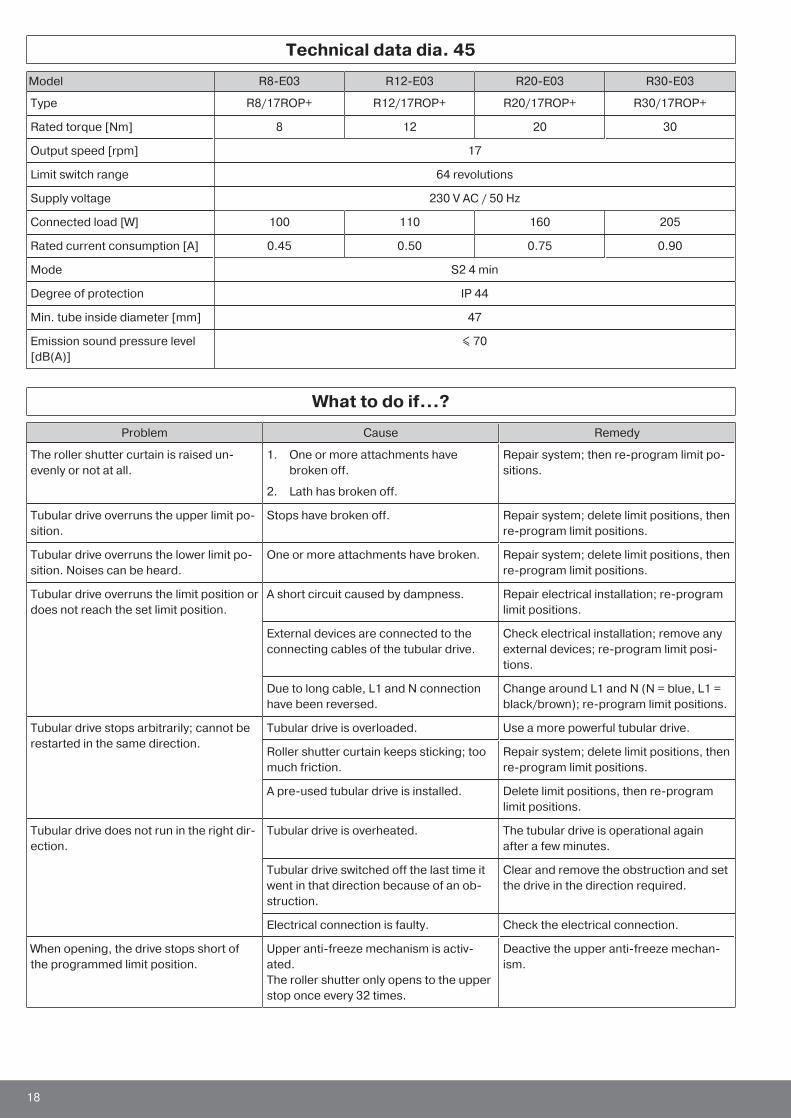
Technical data dia. 45
Model R8-E03 R12-E03 R20-E03 R30-E03
Type R8/17ROP+ R12/17ROP+ R20/17ROP+ R30/17ROP+
Rated torque [Nm] 8 12 20 30
Output speed [rpm] 17
Limit switch range 64 revolutions
Supply voltage 230 V AC / 50 Hz
Connected load [W] 100 110 160 205
Rated current consumption [A] 0.45 0.50 0.75 0.90
Mode S2 4 min
Degree of protection IP 44
Min. tube inside diameter [mm] 47
Emission sound pressure level[dB(A)]
≤ 70
What to do if...?
Problem Cause Remedy
The roller shutter curtain is raised un-evenly or not at all.
1. One or more attachments havebroken off.
2. Lath has broken off.
Repair system; then re-program limit po-sitions.
Tubular drive overruns the upper limit po-sition.
Stops have broken off. Repair system; delete limit positions, thenre-program limit positions.
Tubular drive overruns the lower limit po-sition. Noises can be heard.
One or more attachments have broken. Repair system; delete limit positions, thenre-program limit positions.
Tubular drive overruns the limit position ordoes not reach the set limit position.
A short circuit caused by dampness. Repair electrical installation; re-programlimit positions.
External devices are connected to theconnecting cables of the tubular drive.
Check electrical installation; remove anyexternal devices; re-program limit posi-tions.
Due to long cable, L1 and N connectionhave been reversed.
Change around L1 and N (N = blue, L1 =black/brown); re-program limit positions.
Tubular drive stops arbitrarily; cannot berestarted in the same direction.
Tubular drive is overloaded. Use a more powerful tubular drive.
Roller shutter curtain keeps sticking; toomuch friction.
Repair system; delete limit positions, thenre-program limit positions.
A pre-used tubular drive is installed. Delete limit positions, then re-programlimit positions.
Tubular drive does not run in the right dir-ection.
Tubular drive is overheated. The tubular drive is operational againafter a few minutes.
Tubular drive switched off the last time itwent in that direction because of an ob-struction.
Clear and remove the obstruction and setthe drive in the direction required.
Electrical connection is faulty. Check the electrical connection.
When opening, the drive stops short ofthe programmed limit position.
Upper anti-freeze mechanism is activ-ated.The roller shutter only opens to the upperstop once every 32 times.
Deactive the upper anti-freeze mechan-ism.
18
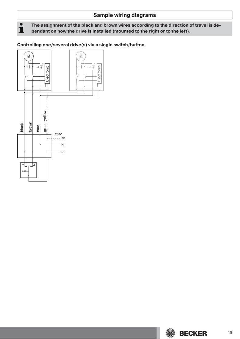
Sample wiring diagrams
The assignment of the black and brown wires according to the direction of travel is de-pendant on how the drive is installed (mounted to the right or to the left).
Controlling one/several drive(s) via a single switch/buttonE
lec
tro
nic
bla
ck
bro
wn
blu
e
gre
en
-ye
llo
w
Ele
ctr
on
ic
19
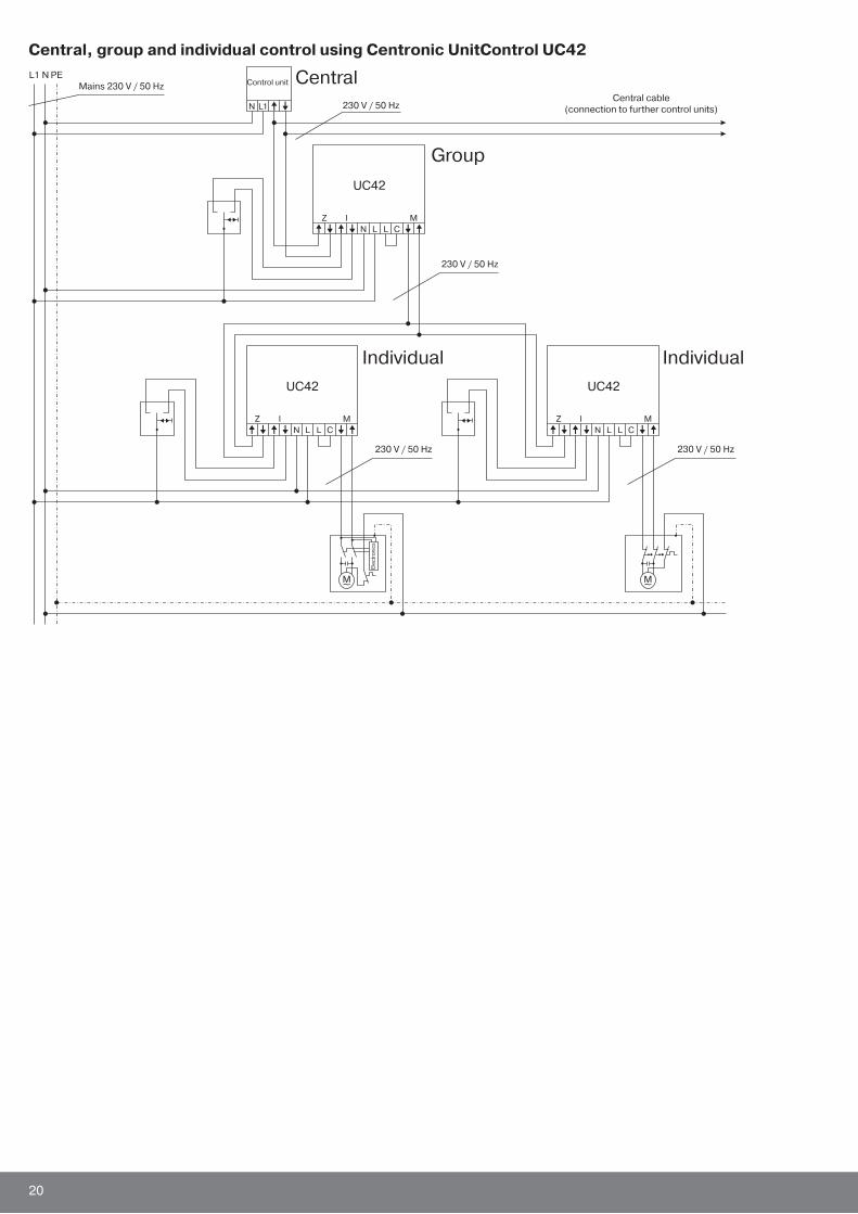
Central, group and individual control using Centronic UnitControl UC42
Mains 230 V / 50 HzCentral
Group
Individual Individual
230 V / 50 HzCentral cable
(connection to further control units)
230 V / 50 Hz
230 V / 50 Hz
Ele
ctr
on
ics
230 V / 50 Hz
Control unit
20
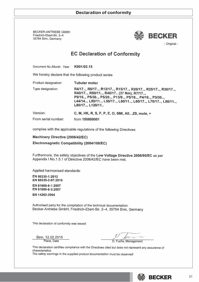
Declaration of conformity
21

22

23

2010 300 546 0b 16/10/2015


![Ppt2 e03.pptm [autoguardado]](https://img.pdfslide.net/doc/110x75/58778b451a28abc85f8b73f7/ppt2-e03pptm-autoguardado.jpg)