Embed Size (px)
DESCRIPTION
wood
Citation preview
Chappell Universal Framing Square
The Chappell Universal Squaretm Puts a Wealth of Building Knowledge Right in the
Palm of your Hand...
You now have the power to create!
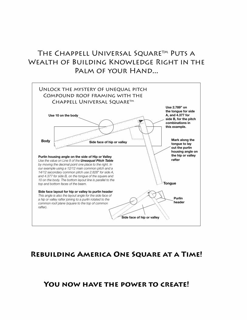
Purlin housing angle on the side of Hip or ValleyUse the value on Line 8 of the Uneaqual Pitch Table by moving the decimal point one place to the right. In our example using a 12/12 main common pitch and a 14/12 secondary common pitch use 2.828” for side A, and 4.377 for side B, on the tongue of the square and 10 on the body. The bottom layout line is parallel to the top and bottom faces of the beam.
Side face layout for hip or valley to purlin headerThis angle is also the layout angle for the side face of a hip or valley rafter joining to a purlin rotated to the common roof plane (square to the top of common rafter).
Tongue
Body Mark along the tongue to lay out the purlin housing angle on the hip or valley rafter
Use 2.789” on the tongue for side A, and 4.377 for side B, for the pitch combinations in this example.
Use 10 on the body
CHAPPELL
UNEQUAL PITCHED
12/12 MAIN PITCH A
1
1
2
3
4
5
6
7
8
9
10
11
12
13
14
15
16
17
18
19
20
21
22
EQ
UA
L P
ITC
HE
D
RA
FTE
R T
AB
LE
2
3
4
5
6
7
8
9
10
11
12
13
14
15
16
17
1
2
3
4
5
6
7
8
9
10
11
12
13
14
15
1
2
3
4
5
6
7
8
9
10
11
12
13
14
15
16
17
18
19
20
21
22
23
CHAPPELL
UNEQ
UAL PIT
CHED
12/12 M
AIN P
ITC
H A
1
1
2
3
4
5
6
7
8
9
10
11
12
13
14
15
16
17
18
19
20
21
22
EQ
UAL P
ITC
HED
RAFTER T
ABLE
2
3
4
5
6
7
8
9
10
11
12
13
14
15
16
17
1
2
3
4
5
6
7
8
9
10
11
12
13
14
15
1
2
3
4
5
6
7
8
9
10
11
12
13
14
15
16
17
18
19
20
21
22
23
Purlin header
Side face of hip or valley
Side face of hip or valley
Unlock the mystery of unequal pitch Compound roof framing with the
Chappell Universal Squaretm
Rebuilding America One Square at a Time!
Chappell Universal Square �
Chappell Universal Framing Squaretm
“It would be part of my scheme
of physical education that every
youth in the state should learn to do
something finely and thoroughly with
his hand, so as to let him know what
touch meant...
Let him once learn to take a straight
shaving off a plank, or draw a fine
curve without faltering, or lay a brick
level in its mortar; and he has learned
a multitude of other matters...”
—John Ruskin
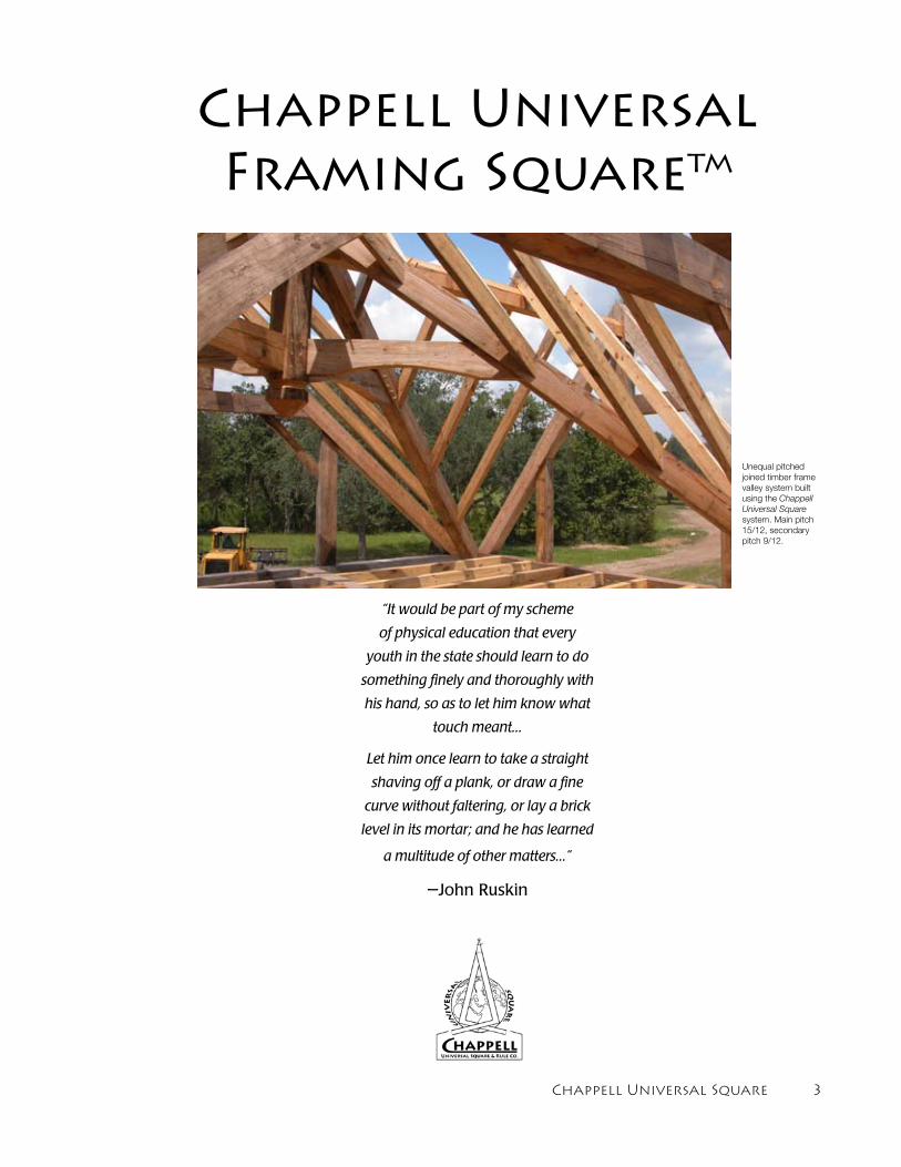
Unequal pitched joined timber frame valley system built using the Chappell Universal Square system. Main pitch 15/12, secondary pitch 9/12.
� Chappell Universal Square
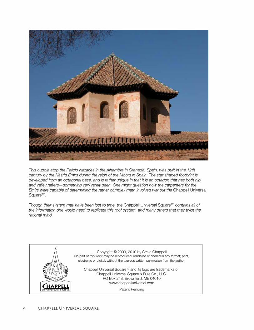
This cupola atop the Palicio Nazaries in the Alhambra in Granada, Spain, was built in the 12th century by the Nasrid Emirs during the reign of the Moors in Spain. The star shaped footprint is developed from an octagonal base, and is rather unique in that it is an octagon that has both hip and valley rafters—something very rarely seen. One might question how the carpenters for the Emirs were capable of determining the rather complex math involved without the Chappell Universal SquareTM.
Though their system may have been lost to time, the Chappell Universal SquareTM contains all of the information one would need to replicate this roof system, and many others that may twist the rational mind.
Copyright © 2009, 2010 by Steve ChappellNo part of this work may be reproduced, rendered or shared in any format; print,
electronic or digital, without the express written permission from the author.
Chappell Universal SquareTM and its logo are trademarks of: Chappell Universal Square & Rule Co., LLC.
PO Box 248, Brownfield, ME 04010www.chappelluniversal.com
Patent Pending
Chappell Universal Square �
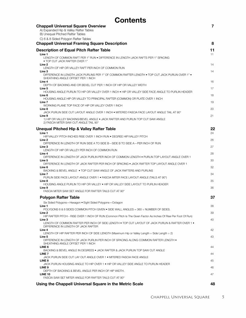
ContentsChappell Universal Square Overview 7 A) Expanded Hip & Valley Rafter Tables
B) Unequal Pitched Rafter Tables
C) 6 & 8 Sided Polygon Rafter Tables
Chappell Universal Framing Square Description 8
Description of Equal Pitch Rafter Table 11 Line 1 11
LENGTH OF COMMON RAFT PER 1” RUN • DIFFERENCE IN LENGTH JACK RAFTS PER 1” SPACING • TOP CUT JACK RAFTER OVER 1” Line 2 14 LENGTH OF HIP OR VALLEY RAFT PER INCH OF COMMON RUN Line 3 14 DIFFERENCE IN LENGTH JACK PURLINS PER 1” OF COMMON RAFTER LENGTH • TOP CUT JACK PURLIN OVER 1” • SHEATHING ANGLE OFFSET PER 1 INCH Line 4 16 DEPTH OF BACKING AND OR BEVEL CUT PER 1 INCH OF HIP OR VALLEY WIDTH Line 5 17 HOUSING ANGLE PURLIN TO HIP OR VALLEY OVER 1 INCH • HIP OR VALLEY SIDE FACE ANGLE TO PURLIN HEADER Line 6 18 HOUSING ANGLE HIP OR VALLEY TO PRINCIPAL RAFTER (COMMON) OR PLATE OVER 1 INCH Line 7 19 WORKING PLANE TOP FACE OF HIP OR VALLEY OVER 1 INCH Line 8 20 JACK PURLIN SIDE CUT LAYOUT ANGLE OVER 1 INCH • MITERED FASCIA FACE LAYOUT ANGLE TAIL AT 90° Line 9 21 1) HIP OR VALLEY BACKING/BEVEL ANGLE • JACK RAFTER AND PURLIN TOP CUT SAW ANGLE
2) FASCIA MITER SAW CUT ANGLE TAIL 90°
Unequal Pitched Hip & Valley Rafter Table 22 Line 1 24 HIP/VALLEY PITCH INCHES RISE OVER 1 INCH RUN • DEGREE HIP/VALLEY PITCH Line 2 26 DIFFERENCE IN LENGTH OF RUN SIDE A TO SIDE B—SIDE B TO SIDE A—PER INCH OF RUN Line 3 27 LENGTH OF HIP OR VALLEY PER INCH OF COMMON RUN Line 4 28 DIFFERENCE IN LENGTH OF JACK PURLIN PER INCH OF COMMON LENGTH • PURLIN TOP LAYOUT ANGLE OVER 1 Line 5 30 DIFFERENCE IN LENGTH OF JACK RAFTER PER INCH OF SPACING • JACK RAFTER TOP LAYOUT ANGLE OVER 1 Line 6 32 BACKING & BEVEL ANGLE • TOP CUT SAW ANGLE OF JACK RAFTERS AND PURLINS Line 7 34 PURLIN SIDE FACE LAYOUT ANGLE OVER 1 • FASCIA MITER FACE LAYOUT ANGLE (TAILS AT 90°) Line 8 35 HOUSING ANGLE PURLIN TO HIP OR VALLEY • HIP OR VALLEY SIDE LAYOUT TO PURLIN HEADER Line 9 36
FASCIA MITER SAW SET ANGLE FOR RAFTER TAILS CUT AT 90°
Polygon Rafter Table 37 Six Sided Polygons—Hexagon • Eight Sided Polygons—Octagon Line 1 38 POLYGONS 6 & 8 SIDES COMMON PITCH GIVEN • SIDE WALL ANGLES = 360 ÷ NUMBER OF SIDES. Line 2 39 HIP RAFTER PITCH - RISE OVER 1 INCH OF RUN (Common Pitch Is The Given Factor As Inches Of Rise Per Foot Of Run) Line 3 40 LENGTH OF COMMON RAFTER PER INCH OF SIDE LENGTH • TOP CUT LAYOUT OF JACK PURLIN & RAFTER OVER 1 • DIFFERENCE IN LENGTH OF JACK RAFTER Line 4 42 LENGTH OF HIP RAFTER PER INCH OF SIDE LENGTH (Maximum Hip or Valley Length = Side Length ÷ 2) Line 5 43 DIFFERENCE IN LENGTH OF JACK PURLIN PER INCH OF SPACING ALONG COMMON RAFTER LENGTH •
SHEATHING ANGLE OFFSET PER 1 INCH LINE 6 44 BACKING & BEVEL ANGLE IN DEGREES • JACK RAFTER & JACK PURLIN TOP SAW CUT ANGLE LINE 7 44 JACK PURLIN SIDE CUT LAY OUT ANGLE OVER 1 • MITERED FASCIA FACE ANGLE LINE 8 45 JACK PURLIN HOUSING ANGLE TO HIP OVER 1 • HIP OR VALLEY SIDE ANGLE TO PURLIN HEADER LINE 9 46 DEPTH OF BACKING & BEVEL ANGLE PER INCH OF HIP WIDTH. LINE 10 47 FASCIA SAW SET MITER ANGLE FOR RAFTER TAILS CUT AT 90°
Using the Chappell Universal Square in the Metric Scale 48
� Chappell Universal Square
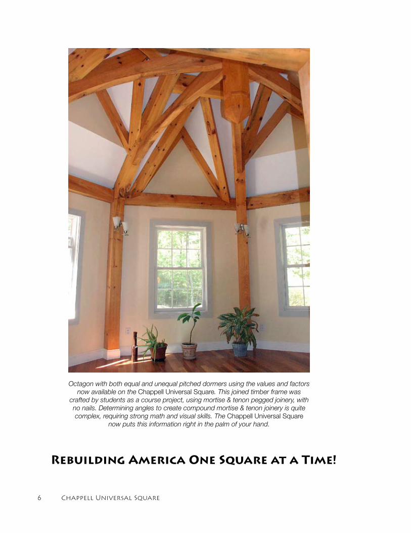
Octagon with both equal and unequal pitched dormers using the values and factors now available on the Chappell Universal Square. This joined timber frame was
crafted by students as a course project, using mortise & tenon pegged joinery, with no nails. Determining angles to create compound mortise & tenon joinery is quite complex, requiring strong math and visual skills. The Chappell Universal Square
now puts this information right in the palm of your hand.
Rebuilding America One Square at a Time!
Chappell Universal Square �
Chappell Universal Square
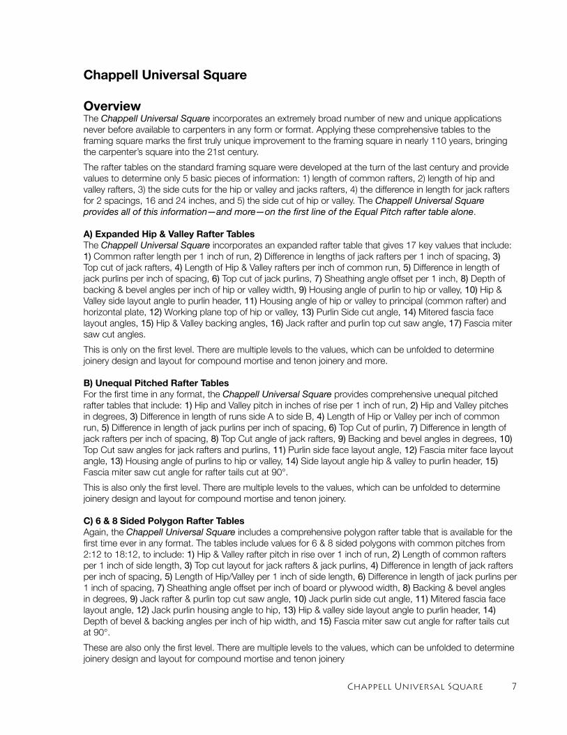
OverviewThe Chappell Universal Square incorporates an extremely broad number of new and unique applications never before available to carpenters in any form or format. Applying these comprehensive tables to the framing square marks the first truly unique improvement to the framing square in nearly 110 years, bringing the carpenter’s square into the 21st century.
The rafter tables on the standard framing square were developed at the turn of the last century and provide values to determine only 5 basic pieces of information: 1) length of common rafters, 2) length of hip and valley rafters, 3) the side cuts for the hip or valley and jacks rafters, 4) the difference in length for jack rafters for 2 spacings, 16 and 24 inches, and 5) the side cut of hip or valley. The Chappell Universal Square provides all of this information—and more—on the first line of the Equal Pitch rafter table alone.
A) Expanded Hip & Valley Rafter TablesThe Chappell Universal Square incorporates an expanded rafter table that gives 17 key values that include: 1) Common rafter length per 1 inch of run, 2) Difference in lengths of jack rafters per 1 inch of spacing, 3) Top cut of jack rafters, 4) Length of Hip & Valley rafters per inch of common run, 5) Difference in length of jack purlins per inch of spacing, 6) Top cut of jack purlins, 7) Sheathing angle offset per 1 inch, 8) Depth of backing & bevel angles per inch of hip or valley width, 9) Housing angle of purlin to hip or valley, 10) Hip & Valley side layout angle to purlin header, 11) Housing angle of hip or valley to principal (common rafter) and horizontal plate, 12) Working plane top of hip or valley, 13) Purlin Side cut angle, 14) Mitered fascia face layout angles, 15) Hip & Valley backing angles, 16) Jack rafter and purlin top cut saw angle, 17) Fascia miter saw cut angles.
This is only on the first level. There are multiple levels to the values, which can be unfolded to determine joinery design and layout for compound mortise and tenon joinery and more.
B) Unequal Pitched Rafter TablesFor the first time in any format, the Chappell Universal Square provides comprehensive unequal pitched rafter tables that include: 1) Hip and Valley pitch in inches of rise per 1 inch of run, 2) Hip and Valley pitches in degrees, 3) Difference in length of runs side A to side B, 4) Length of Hip or Valley per inch of common run, 5) Difference in length of jack purlins per inch of spacing, 6) Top Cut of purlin, 7) Difference in length of jack rafters per inch of spacing, 8) Top Cut angle of jack rafters, 9) Backing and bevel angles in degrees, 10) Top Cut saw angles for jack rafters and purlins, 11) Purlin side face layout angle, 12) Fascia miter face layout angle, 13) Housing angle of purlins to hip or valley, 14) Side layout angle hip & valley to purlin header, 15) Fascia miter saw cut angle for rafter tails cut at 90°.
This is also only the first level. There are multiple levels to the values, which can be unfolded to determine joinery design and layout for compound mortise and tenon joinery.
C) 6 & 8 Sided Polygon Rafter TablesAgain, the Chappell Universal Square includes a comprehensive polygon rafter table that is available for the first time ever in any format. The tables include values for 6 & 8 sided polygons with common pitches from 2:12 to 18:12, to include: 1) Hip & Valley rafter pitch in rise over 1 inch of run, 2) Length of common rafters per 1 inch of side length, 3) Top cut layout for jack rafters & jack purlins, 4) Difference in length of jack rafters per inch of spacing, 5) Length of Hip/Valley per 1 inch of side length, 6) Difference in length of jack purlins per 1 inch of spacing, 7) Sheathing angle offset per inch of board or plywood width, 8) Backing & bevel angles in degrees, 9) Jack rafter & purlin top cut saw angle, 10) Jack purlin side cut angle, 11) Mitered fascia face layout angle, 12) Jack purlin housing angle to hip, 13) Hip & valley side layout angle to purlin header, 14) Depth of bevel & backing angles per inch of hip width, and 15) Fascia miter saw cut angle for rafter tails cut at 90°.
These are also only the first level. There are multiple levels to the values, which can be unfolded to determine joinery design and layout for compound mortise and tenon joinery
� Chappell Universal Square
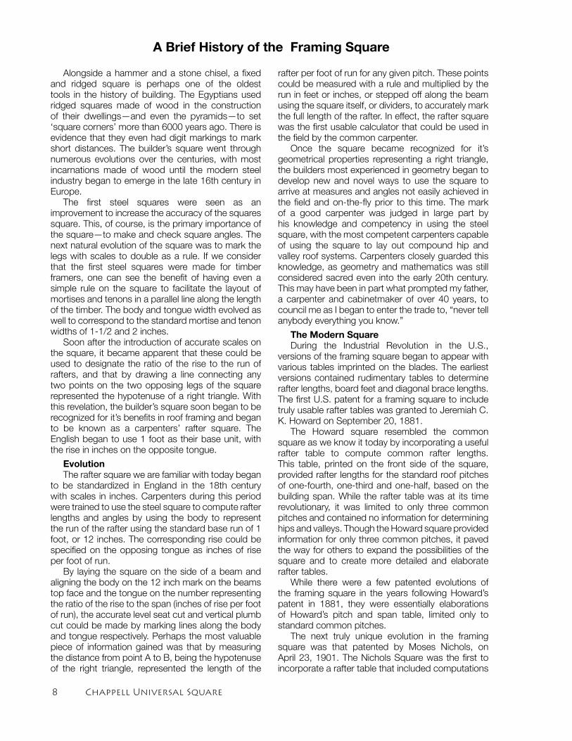
Alongside a hammer and a stone chisel, a fixed and ridged square is perhaps one of the oldest tools in the history of building. The Egyptians used ridged squares made of wood in the construction of their dwellings—and even the pyramids—to set ‘square corners’ more than 6000 years ago. There is evidence that they even had digit markings to mark short distances. The builder’s square went through numerous evolutions over the centuries, with most incarnations made of wood until the modern steel industry began to emerge in the late 16th century in Europe.
The first steel squares were seen as an improvement to increase the accuracy of the squares square. This, of course, is the primary importance of the square—to make and check square angles. The next natural evolution of the square was to mark the legs with scales to double as a rule. If we consider that the first steel squares were made for timber framers, one can see the benefit of having even a simple rule on the square to facilitate the layout of mortises and tenons in a parallel line along the length of the timber. The body and tongue width evolved as well to correspond to the standard mortise and tenon widths of 1-1/2 and 2 inches.
Soon after the introduction of accurate scales on the square, it became apparent that these could be used to designate the ratio of the rise to the run of rafters, and that by drawing a line connecting any two points on the two opposing legs of the square represented the hypotenuse of a right triangle. With this revelation, the builder’s square soon began to be recognized for it’s benefits in roof framing and began to be known as a carpenters’ rafter square. The English began to use 1 foot as their base unit, with the rise in inches on the opposite tongue.
EvolutionThe rafter square we are familiar with today began
to be standardized in England in the 18th century with scales in inches. Carpenters during this period were trained to use the steel square to compute rafter lengths and angles by using the body to represent the run of the rafter using the standard base run of 1 foot, or 12 inches. The corresponding rise could be specified on the opposing tongue as inches of rise per foot of run.
By laying the square on the side of a beam and aligning the body on the 12 inch mark on the beams top face and the tongue on the number representing the ratio of the rise to the span (inches of rise per foot of run), the accurate level seat cut and vertical plumb cut could be made by marking lines along the body and tongue respectively. Perhaps the most valuable piece of information gained was that by measuring the distance from point A to B, being the hypotenuse of the right triangle, represented the length of the
rafter per foot of run for any given pitch. These points could be measured with a rule and multiplied by the run in feet or inches, or stepped off along the beam using the square itself, or dividers, to accurately mark the full length of the rafter. In effect, the rafter square was the first usable calculator that could be used in the field by the common carpenter.
Once the square became recognized for it’s geometrical properties representing a right triangle, the builders most experienced in geometry began to develop new and novel ways to use the square to arrive at measures and angles not easily achieved in the field and on-the-fly prior to this time. The mark of a good carpenter was judged in large part by his knowledge and competency in using the steel square, with the most competent carpenters capable of using the square to lay out compound hip and valley roof systems. Carpenters closely guarded this knowledge, as geometry and mathematics was still considered sacred even into the early 20th century. This may have been in part what prompted my father, a carpenter and cabinetmaker of over 40 years, to council me as I began to enter the trade to, “never tell anybody everything you know.”
The Modern SquareDuring the Industrial Revolution in the U.S.,
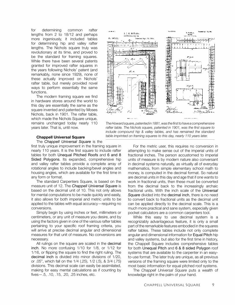
versions of the framing square began to appear with various tables imprinted on the blades. The earliest versions contained rudimentary tables to determine rafter lengths, board feet and diagonal brace lengths. The first U.S. patent for a framing square to include truly usable rafter tables was granted to Jeremiah C. K. Howard on September 20, 1881.
The Howard square resembled the common square as we know it today by incorporating a useful rafter table to compute common rafter lengths. This table, printed on the front side of the square, provided rafter lengths for the standard roof pitches of one-fourth, one-third and one-half, based on the building span. While the rafter table was at its time revolutionary, it was limited to only three common pitches and contained no information for determining hips and valleys. Though the Howard square provided information for only three common pitches, it paved the way for others to expand the possibilities of the square and to create more detailed and elaborate rafter tables.
While there were a few patented evolutions of the framing square in the years following Howard’s patent in 1881, they were essentially elaborations of Howard’s pitch and span table, limited only to standard common pitches.
The next truly unique evolution in the framing square was that patented by Moses Nichols, on April 23, 1901. The Nichols Square was the first to incorporate a rafter table that included computations
A Brief History of the Framing Square
Chappell Universal Square �
for determining common rafter lengths from 2 to 18/12 and perhaps more ingeniously, it included tables for determining hip and valley rafter lengths. The Nichols square truly was revolutionary at its time, and proved to be the standard for framing squares. While there have been several patents granted for improved rafter squares in the years following Nichols’ patent (and remarkably, none since 1929), none of these actually improved on Nichols’ rafter table, but merely provided novel ways to perform essentially the same functions.
The modern framing square we find in hardware stores around the world to this day are essentially the same as the square invented and patented by Moses Nichols, back in 1901. The rafter table, which made the Nichols Square unique, remains unchanged today nearly 110 years later. That is, until now.
For the metric user, this requires no conversion in attempting to make sense out of the imperial units of fractional inches. The person accustomed to imperial units of measure is by modern nature also conversant in decimal systems naturally, as virtually all of everyday mathematics, from simple elementary school math to money, is computed in the decimal format. So natural are decimal units in this day and age that if one wants to work in fractional units, then these must be converted from the decimal back to the increasingly archaic fractional units. With the inch scale of the Universal Square divided into the decimal inch, there is no need to convert back to fractional units as the decimal unit can be applied directly to the decimal scale. This is a much more practical and sane system, especially given pocket calculators are a common carpenters tool.
While this easy to use decimal system is a recognizably advantageous feature, it is only a small part of the remarkable features embodied in the squares rafter tables. These tables include not only complete angular and dimensional information for Equal Pitch hip and valley systems, but also for the first time in history, the Chappell Square includes comprehensive tables for both Unequal Pitch and 6 & 8 sided Polygon roof systems that are available to the carpenter in an easy-to-use format. The later truly are unique, as all previous versions of the framing square were limited only to the most basic information for equal pitched roof systems.
The Chappell Universal Square puts a wealth of knowledge right in the palm of your hand.
The Howard square, patented in 1881, was the first to have a comprehensive rafter table. The Nichols square, patented in 1901, was the first square to include compound hip & valley tables, and has remained the standard table imprinted on framing squares to this day, nearly 110 years later. Chappell Universal Square
The Chappell Universal Square is the first truly unique improvement in the framing square in nearly 110 years. It is the first square to include rafter tables for both Unequal Pitched Roofs and 6 and 8 Sided Polygons. Its expanded, comprehensive hip and valley rafter tables provide a complete array of rotational angles to include backing/bevel angles and housing angles, which are available for the first time in any form or format.
The standard Carpenters Square, is based on the measure unit of 12. The Chappell Universal Square is based on the decimal unit of 10. This not only allows for mental computations to be made quickly and easily, it also allows for both imperial and metric units to be applied to the tables with equal accuracy—requiring no conversions.
Simply begin by using inches or feet, millimeters or centimeters, or any unit of measure you desire, and by using the factors given in one of the various rafter tables pertaining to your specific roof framing criteria, you will arrive at precise decimal angular and dimensional measures for that unit of measure. No conversions are necessary.
All rulings on the square are scaled in the decimal inch. No more confusing 1/10 for 1/8, or 1/12 for 1/16, or flipping the square to find the right ruling. The decimal inch is divided into minor divisions of 1/20, or .05”, which fall on the 1/4 (.25), 1/2 (.5), & 3/4 (.75) divisions. This decimal scale can easily be assimilated, making for easy mental calculations as if counting by fives—.5, .10, .15, .20, .25 inches, etc.
10 Chappell Universal Square
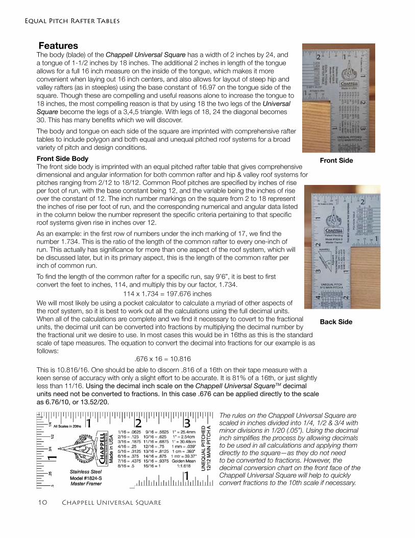
FeaturesThe body (blade) of the Chappell Universal Square has a width of 2 inches by 24, and a tongue of 1-1/2 inches by 18 inches. The additional 2 inches in length of the tongue allows for a full 16 inch measure on the inside of the tongue, which makes it more convenient when laying out 16 inch centers, and also allows for layout of steep hip and valley rafters (as in steeples) using the base constant of 16.97 on the tongue side of the square. Though these are compelling and useful reasons alone to increase the tongue to 18 inches, the most compelling reason is that by using 18 the two legs of the Universal Square become the legs of a 3,4,5 triangle. With legs of 18, 24 the diagonal becomes 30. This has many benefits which we will discover.
The body and tongue on each side of the square are imprinted with comprehensive rafter tables to include polygon and both equal and unequal pitched roof systems for a broad variety of pitch and design conditions.
Front Side BodyThe front side body is imprinted with an equal pitched rafter table that gives comprehensive dimensional and angular information for both common rafter and hip & valley roof systems for pitches ranging from 2/12 to 18/12. Common Roof pitches are specified by inches of rise per foot of run, with the base constant being 12, and the variable being the inches of rise over the constant of 12. The inch number markings on the square from 2 to 18 represent the inches of rise per foot of run, and the corresponding numerical and angular data listed in the column below the number represent the specific criteria pertaining to that specific roof systems given rise in inches over 12.
As an example: in the first row of numbers under the inch marking of 17, we find the number 1.734. This is the ratio of the length of the common rafter to every one-inch of run. This actually has significance for more than one aspect of the roof system, which will be discussed later, but in its primary aspect, this is the length of the common rafter per inch of common run.
To find the length of the common rafter for a specific run, say 9’6”, it is best to first convert the feet to inches, 114, and multiply this by our factor, 1.734.
114 x 1.734 = 197.676 inchesWe will most likely be using a pocket calculator to calculate a myriad of other aspects of the roof system, so it is best to work out all the calculations using the full decimal units. When all of the calculations are complete and we find it necessary to covert to the fractional units, the decimal unit can be converted into fractions by multiplying the decimal number by the fractional unit we desire to use. In most cases this would be in 16ths as this is the standard scale of tape measures. The equation to convert the decimal into fractions for our example is as follows: .676 x 16 = 10.816
This is 10.816/16. One should be able to discern .816 of a 16th on their tape measure with a keen sense of accuracy with only a slight effort to be accurate. It is 81% of a 16th, or just slightly less than 11/16. Using the decimal inch scale on the Chappell Universal SquareTM decimal units need not be converted to fractions. In this case .676 can be applied directly to the scale as 6.76/10, or 13.52/20.
Equal Pitch Rafter Tables
The rules on the Chappell Universal Square are scaled in inches divided into 1/4, 1/2 & 3/4 with minor divisions in 1/20 (.05”). Using the decimal inch simplifies the process by allowing decimals to be used in all calculations and applying them directly to the square—as they do not need to be converted to fractions. However, the decimal conversion chart on the front face of the Chappell Universal Square will help to quickly convert fractions to the 10th scale if necessary.
Front Side
Back Side
Chappell Universal Square 11
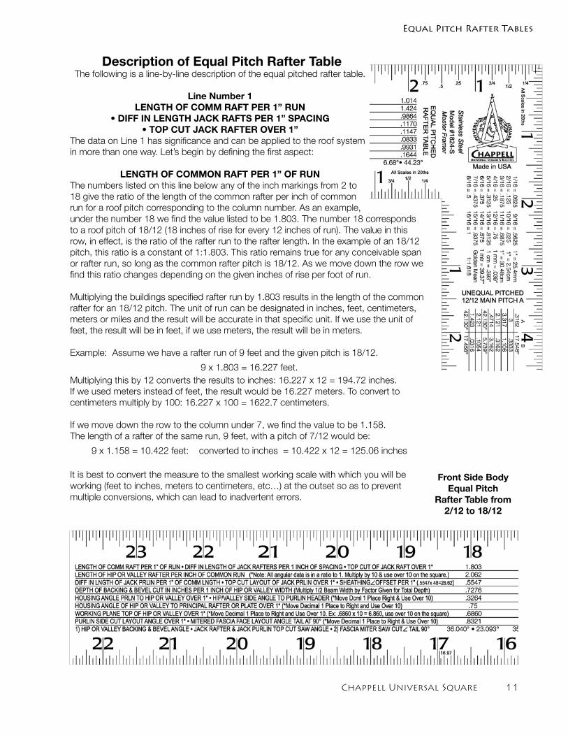
Description of Equal Pitch Rafter TableThe following is a line-by-line description of the equal pitched rafter table.
Line Number 1LENGTH OF COMM RAFT PER 1” RUN
• DIFF IN LENGTH JACK RAFTS PER 1” SPACING • TOP CUT JACK RAFTER OVER 1”
The data on Line 1 has significance and can be applied to the roof system in more than one way. Let’s begin by defining the first aspect:
LENGTH OF COMMON RAFT PER 1” OF RUNThe numbers listed on this line below any of the inch markings from 2 to 18 give the ratio of the length of the common rafter per inch of common run for a roof pitch corresponding to the column number. As an example, under the number 18 we find the value listed to be 1.803. The number 18 corresponds to a roof pitch of 18/12 (18 inches of rise for every 12 inches of run). The value in this row, in effect, is the ratio of the rafter run to the rafter length. In the example of an 18/12 pitch, this ratio is a constant of 1:1.803. This ratio remains true for any conceivable span or rafter run, so long as the common rafter pitch is 18/12. As we move down the row we find this ratio changes depending on the given inches of rise per foot of run.
Multiplying the buildings specified rafter run by 1.803 results in the length of the common rafter for an 18/12 pitch. The unit of run can be designated in inches, feet, centimeters, meters or miles and the result will be accurate in that specific unit. If we use the unit of feet, the result will be in feet, if we use meters, the result will be in meters.
Example: Assume we have a rafter run of 9 feet and the given pitch is 18/12.
9 x 1.803 = 16.227 feet. Multiplying this by 12 converts the results to inches: 16.227 x 12 = 194.72 inches.If we used meters instead of feet, the result would be 16.227 meters. To convert to centimeters multiply by 100: 16.227 x 100 = 1622.7 centimeters.
If we move down the row to the column under 7, we find the value to be 1.158.The length of a rafter of the same run, 9 feet, with a pitch of 7/12 would be:
9 x 1.158 = 10.422 feet: converted to inches = 10.422 x 12 = 125.06 inches
It is best to convert the measure to the smallest working scale with which you will be working (feet to inches, meters to centimeters, etc…) at the outset so as to prevent multiple conversions, which can lead to inadvertent errors.
Equal Pitch Rafter Tables
Front Side Body Equal Pitch
Rafter Table from 2/12 to 18/12
12 Chappell Universal Square
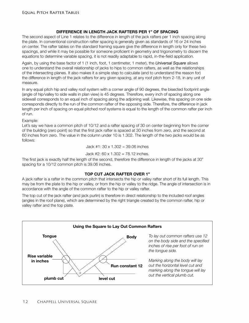
DIFFERENCE IN LENGTH JACK RAFTERS PER 1” OF SPACINGThe second aspect of Line 1 relates to the difference in length of the jack rafters per 1 inch spacing along the plate. In conventional construction rafter spacing is generally given as standards of 16 or 24 inches on center. The rafter tables on the standard framing square give the difference in length only for these two spacings, and while it may be possible for someone proficient in geometry and trigonometry to discern the equations to determine variable spacing, it is not readily adaptable to rapid, in-the-field application.
Again, by using the base factor of 1 (1 inch, foot, 1 centimeter, 1 meter), the Universal Square allows one to understand the overall relationship of jacks to hips to common rafters, as well as the relationships of the intersecting planes. It also makes it a simple step to calculate (and to understand the reason for) the difference in length of the jack rafters for any given spacing, at any roof pitch from 2-18, in any unit of measure.
In any equal pitch hip and valley roof system with a corner angle of 90 degrees, the bisected footprint angle (angle of hip/valley to side walls in plan view) is 45 degrees. Therefore, every inch of spacing along one sidewall corresponds to an equal inch of spacing along the adjoining wall. Likewise, this spacing on one side corresponds directly to the run of the common rafter of the opposing side. Therefore, the difference in jack length per inch of spacing on equal pitched roof systems is equal to the length of the common rafter per inch of run.
Example:Let’s say we have a common pitch of 10/12 and a rafter spacing of 30 on center beginning from the corner of the building (zero point) so that the first jack rafter is spaced at 30 inches from zero, and the second at 60 inches from zero. The value in the column under 10 is 1.302. The length of the two jacks would be as follows:
Jack #1: 30 x 1.302 = 39.06 inches
Jack #2: 60 x 1.302 = 78.12 inches. The first jack is exactly half the length of the second, therefore the difference in length of the jacks at 30” spacing for a 10/12 common pitch is 39.06 inches.
TOP CUT JACK RAFTER OVER 1”A jack rafter is a rafter in the common pitch that intersects the hip or valley rafter short of its full length. This may be from the plate to the hip or valley, or from the hip or valley to the ridge. The angle of intersection is in accordance with the angle of the common rafter to the hip or valley rafter.
The top cut of the jack rafter (and jack purlin) is therefore in direct relationship to the included roof angles (angles in the roof plane), which are determined by the right triangle created by the common rafter, hip or valley rafter and the top plate.
Equal Pitch Rafter Tables
To lay out common rafters use 12 on the body side and the specified inches of rise per foot of run on the tongue side.
Marking along the body will lay out the horizontal level cut and marking along the tongue will lay out the vertical plumb cut.
CHAPPELL
UN
EQ
UA
L
PIT
CH
ED
12/1
2
MA
IN PITC
H A
1
1
2
3
4
5
6
7
8
9
10
11
12
13
14
15
16
17
18
19
20
21
22
EQ
UA
L PIT
CH
ED
RA
FT
ER
TA
BLE
2
3
4
5
6
7
8
9
10
11
12
13
14
15
16
17
1
2
3
4
5
6
7
8
9
10
11
12
13
14
15
1
2
3
4
5
6
7
8
9
10
11
12
13
14
15
16
17
18
19
20
21
22
23
BodyTongue
level cutplumb cut
Run constant 12
Rise variablein inches
Using the Square to Lay Out Common Rafters
Chappell Universal Square 1�
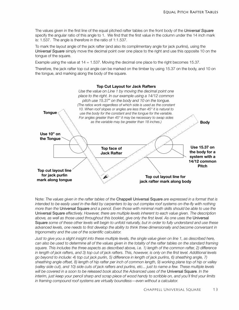
The values given in the first line of the equal pitched rafter tables on the front body of the Universal Square specify the angular ratio of this angle to 1. We find that the first value in the column under the 14 inch mark is: 1.537. The angle is therefore in the ratio of 1:1.537.
To mark the layout angle of the jack rafter (and also its complimentary angle for jack purlins), using the Universal Square simply move the decimal point over one place to the right and use this opposite 10 on the tongue of the square.
Example using the value at 14 = 1.537. Moving the decimal one place to the right becomes 15.37.
Therefore, the jack rafter top cut angle can be marked on the timber by using 15.37 on the body, and 10 on the tongue, and marking along the body of the square.
CHAPPELL
UNEQUAL PITCHED
12/12 MAIN PITCH A
1
1
2
3
4
5
6
7
8
9
10
11
12
13
14
15
16
17
18
19
20
21
22
EQ
UAL P
ITC
HED
RAFTER T
AB
LE
2
3
4
5
6
7
8
9
10
11
12
13
14
15
16
17
1
2
3
4
5
6
7
8
9
10
11
12
13
14
15
1
2
3
4
5
6
7
8
9
10
11
12
13
14
15
16
17
18
19
20
21
22
23 Body
Tongue
Top cut layout line for jack rafter mark along body
Top cut layout line for jack purlin
mark along tongue
Top Cut Layout for Jack RaftersUse the value on Line 1 by moving the decimal point one place to the right. In our example using a 14/12 common
pitch use 15.37” on the body and 10 on the tongue. (The ratios work regardless of which side is used as the constant 10. When roof slopes or angles are less than 45° it is natural to use the body for the constant and the tongue for the variable. For angles greater than 45° it may be necessary to swap sides
as the variable may be greater than 18 inches.)
Use 10” on the Tongue
Use 15.37 on the body for a system with a 14/12 common
Pitch
Top face of Jack Rafter
Equal Pitch Rafter Tables
Note: The values given in the rafter tables of the Chappell Universal Square are expressed in a format that is intended to be easily used in-the-field by carpenters to lay out complex roof systems on-the-fly with nothing more than the Universal Square and a pencil. Even those with minimal math skills should be able to use the Universal Square effectively. However, there are multiple levels inherent to each value given. The description above, as well as those used throughout this booklet, give only the first level. As one uses the Universal Square some of these other levels will begin to unfold naturally, but in order to fully understand and use these advanced levels, one needs to first develop the ability to think three dimensionally and become conversant in trigonometry and the use of the scientific calculator.
Just to give you a slight insight into these multiple levels, the single value given on line 1, as described here, can also be used to determine all of the values given in the totality of the rafter tables on the standard framing square. This includes the three aspects as described above, i.e. 1) length of the common rafter, 2) difference in length of jack rafters, and 3) top cut of jack rafters. This, however, is only on the first level. Additional levels go beyond to include: 4) top cut jack purlin, 5) difference in length of jack purlins, 6) sheathing angle, 7) sheathing angle offset, 8) length of hip rafter per inch of common length, 9) working plane top of hip or valley (valley side cut), and 10) side cuts of jack rafters and purlins, etc... just to name a few. These multiple levels will be covered in a soon to be released book about the Advanced uses of the Universal Square. In the interim, just keep your pencil sharp and scrap piece of wood handy to scribble on, and you’ll find your limits in framing compound roof systems are virtually boundless—even without a calculator.
1� Chappell Universal Square
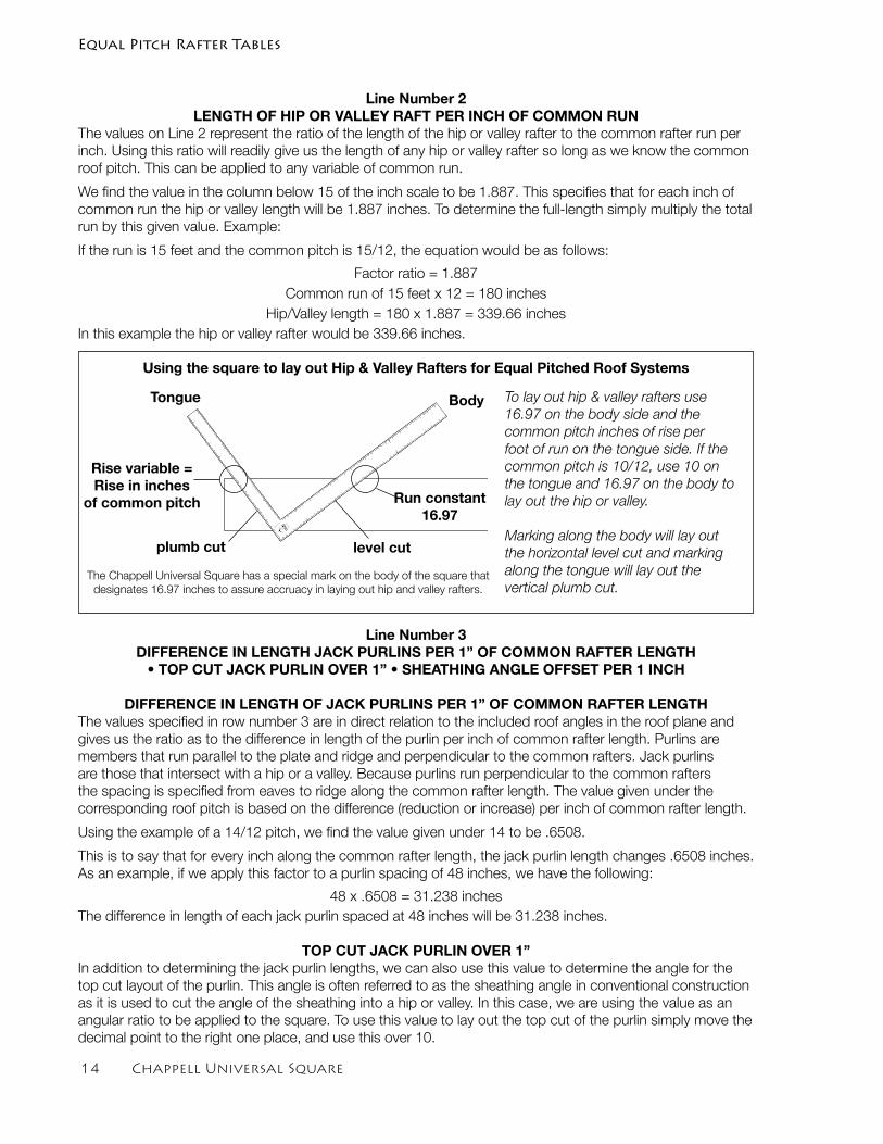
Line Number 2LENGTH OF HIP OR VALLEY RAFT PER INCH OF COMMON RUN
The values on Line 2 represent the ratio of the length of the hip or valley rafter to the common rafter run per inch. Using this ratio will readily give us the length of any hip or valley rafter so long as we know the common roof pitch. This can be applied to any variable of common run.
We find the value in the column below 15 of the inch scale to be 1.887. This specifies that for each inch of common run the hip or valley length will be 1.887 inches. To determine the full-length simply multiply the total run by this given value. Example:
If the run is 15 feet and the common pitch is 15/12, the equation would be as follows:
Factor ratio = 1.887 Common run of 15 feet x 12 = 180 inches
Hip/Valley length = 180 x 1.887 = 339.66 inchesIn this example the hip or valley rafter would be 339.66 inches.
Line Number 3DIFFERENCE IN LENGTH JACK PURLINS PER 1” OF COMMON RAFTER LENGTH
• TOP CUT JACK PURLIN OVER 1” • SHEATHING ANGLE OFFSET PER 1 INCH
DIFFERENCE IN LENGTH OF JACK PURLINS PER 1” OF COMMON RAFTER LENGTHThe values specified in row number 3 are in direct relation to the included roof angles in the roof plane and gives us the ratio as to the difference in length of the purlin per inch of common rafter length. Purlins are members that run parallel to the plate and ridge and perpendicular to the common rafters. Jack purlins are those that intersect with a hip or a valley. Because purlins run perpendicular to the common rafters the spacing is specified from eaves to ridge along the common rafter length. The value given under the corresponding roof pitch is based on the difference (reduction or increase) per inch of common rafter length.
Using the example of a 14/12 pitch, we find the value given under 14 to be .6508.
This is to say that for every inch along the common rafter length, the jack purlin length changes .6508 inches. As an example, if we apply this factor to a purlin spacing of 48 inches, we have the following:
48 x .6508 = 31.238 inches The difference in length of each jack purlin spaced at 48 inches will be 31.238 inches.
TOP CUT JACK PURLIN OVER 1”In addition to determining the jack purlin lengths, we can also use this value to determine the angle for the top cut layout of the purlin. This angle is often referred to as the sheathing angle in conventional construction as it is used to cut the angle of the sheathing into a hip or valley. In this case, we are using the value as an angular ratio to be applied to the square. To use this value to lay out the top cut of the purlin simply move the decimal point to the right one place, and use this over 10.
Equal Pitch Rafter Tables
To lay out hip & valley rafters use 16.97 on the body side and the common pitch inches of rise per foot of run on the tongue side. If the common pitch is 10/12, use 10 on the tongue and 16.97 on the body to lay out the hip or valley.
Marking along the body will lay out the horizontal level cut and marking along the tongue will lay out the vertical plumb cut.
CHAPPELL
UN
EQ
UA
L
PIT
CH
ED
12/1
2
MA
IN PITC
H A
1
1
2
3
4
5
6
7
8
9
10
11
12
13
14
15
16
17
18
19
20
21
22
EQ
UA
L PIT
CH
ED
RA
FT
ER
TA
BLE
2
3
4
5
6
7
8
9
10
11
12
13
14
15
16
17
1
2
3
4
5
6
7
8
9
10
11
12
13
14
15
1
2
3
4
5
6
7
8
9
10
11
12
13
14
15
16
17
18
19
20
21
22
23
BodyTongue
level cutplumb cut
Run constant 16.97
Rise variable =Rise in inches
of common pitch
Using the square to lay out Hip & Valley Rafters for Equal Pitched Roof Systems
The Chappell Universal Square has a special mark on the body of the square that designates 16.97 inches to assure accruacy in laying out hip and valley rafters.
Chappell Universal Square 1�
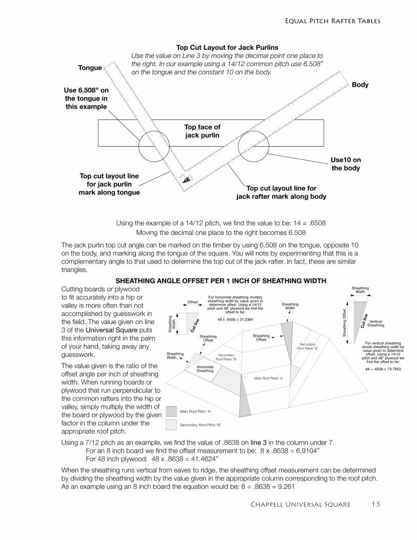
Using the example of a 14/12 pitch, we find the value to be: 14 = .6508 Moving the decimal one place to the right becomes 6.508
The jack purlin top cut angle can be marked on the timber by using 6.508 on the tongue, opposite 10 on the body, and marking along the tongue of the square. You will note by experimenting that this is a complementary angle to that used to determine the top cut of the jack rafter. In fact, these are similar triangles.
SHEATHING ANGLE OFFSET PER 1 INCH OF SHEATHING WIDTHCutting boards or plywood to fit accurately into a hip or valley is more often than not accomplished by guesswork in the field. The value given on line 3 of the Universal Square puts this information right in the palm of your hand, taking away any guesswork.
The value given is the ratio of the offset angle per inch of sheathing width. When running boards or plywood that run perpendicular to the common rafters into the hip or valley, simply multiply the width of the board or plywood by the given factor in the column under the appropriate roof pitch.
Using a 7/12 pitch as an example, we find the value of .8638 on line 3 in the column under 7. For an 8 inch board we find the offset measurement to be: 8 x .8638 = 6.9104” For 48 inch plywood: 48 x .8638 = 41.4624”
When the sheathing runs vertical from eaves to ridge, the sheathing offset measurement can be determined by dividing the sheathing width by the value given in the appropriate column corresponding to the roof pitch. As an example using an 8 inch board the equation would be: 8 ÷ .8638 = 9.261
CHAPPELL
UNEQUAL PITCHED
12/12 MAIN PITCH A
1
1
2
3
4
5
6
7
8
9
10
11
12
13
14
15
16
17
18
19
20
21
22
EQ
UAL P
ITC
HED
RAFTER T
AB
LE
2
3
4
5
6
7
8
9
10
11
12
13
14
15
16
17
1
2
3
4
5
6
7
8
9
10
11
12
13
14
15
1
2
3
4
5
6
7
8
9
10
11
12
13
14
15
16
17
18
19
20
21
22
23 Body
Tongue
Top cut layout line for jack rafter mark along body
Top cut layout line for jack purlin
mark along tongue
Top Cut Layout for Jack PurlinsUse the value on Line 3 by moving the decimal point one place to the right. In our example using a 14/12 common pitch use 6.508” on the tongue and the constant 10 on the body.
Use 6.508” on the tongue in this example
Use10 on the body
Top face of jack purlin
Equal Pitch Rafter Tables
Main Roof Pitch 'A'
Secondary Roof Pitch 'B'
Main Roof Plane 'A'
Secondary
Roof Plane 'B'
Secondary
Roof Plane 'B'
SheathingWidth
SheathingOffset
9.324
Sheathing
Width
4.830Offset
HorizontalSheathing
For horizontal sheathing multiplysheathing width by value given todetermine offset. Using a 14/12
pitch and 48" plywood we find theoffset to be:
48 x .6508 = 31.2384
SheathingWidth
SheathingOffset
For vertical sheathingdivide sheathing width byvalue given to determine
offset. Using a 14/12pitch and 48" plywood we
find the offset to be:
48 ÷ .6508 = 73.7553
VerticalSheathing18
.743
5.550
SheathingWidth
Sh
ea
thin
g O
ffset
Cut
line
Cut
line
1� Chappell Universal Square
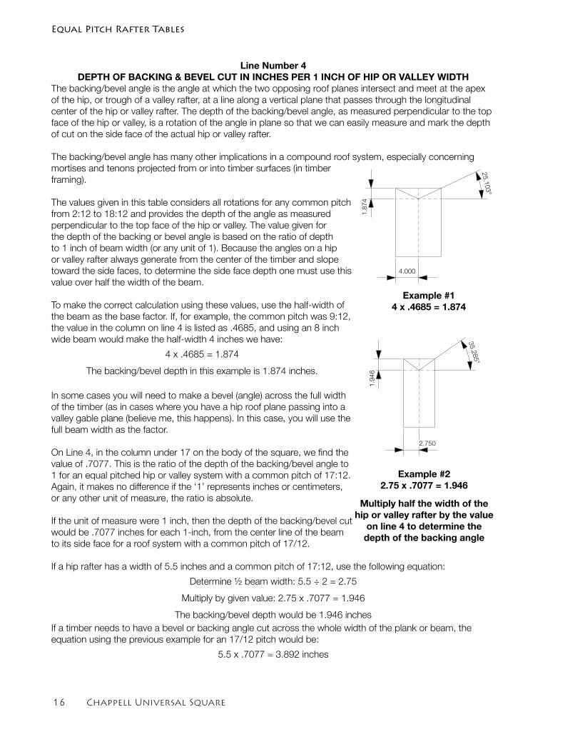
Line Number 4DEPTH OF BACKING & BEVEL CUT IN INCHES PER 1 INCH OF HIP OR VALLEY WIDTH
The backing/bevel angle is the angle at which the two opposing roof planes intersect and meet at the apex of the hip, or trough of a valley rafter, at a line along a vertical plane that passes through the longitudinal center of the hip or valley rafter. The depth of the backing/bevel angle, as measured perpendicular to the top face of the hip or valley, is a rotation of the angle in plane so that we can easily measure and mark the depth of cut on the side face of the actual hip or valley rafter.
The backing/bevel angle has many other implications in a compound roof system, especially concerning mortises and tenons projected from or into timber surfaces (in timber framing).
The values given in this table considers all rotations for any common pitch from 2:12 to 18:12 and provides the depth of the angle as measured perpendicular to the top face of the hip or valley. The value given for the depth of the backing or bevel angle is based on the ratio of depth to 1 inch of beam width (or any unit of 1). Because the angles on a hip or valley rafter always generate from the center of the timber and slope toward the side faces, to determine the side face depth one must use this value over half the width of the beam.
To make the correct calculation using these values, use the half-width of the beam as the base factor. If, for example, the common pitch was 9:12, the value in the column on line 4 is listed as .4685, and using an 8 inch wide beam would make the half-width 4 inches we have:
4 x .4685 = 1.874
The backing/bevel depth in this example is 1.874 inches.
In some cases you will need to make a bevel (angle) across the full width of the timber (as in cases where you have a hip roof plane passing into a valley gable plane (believe me, this happens). In this case, you will use the full beam width as the factor.
On Line 4, in the column under 17 on the body of the square, we find the value of .7077. This is the ratio of the depth of the backing/bevel angle to 1 for an equal pitched hip or valley system with a common pitch of 17:12. Again, it makes no difference if the ‘1’ represents inches or centimeters, or any other unit of measure, the ratio is absolute.
If the unit of measure were 1 inch, then the depth of the backing/bevel cut would be .7077 inches for each 1-inch, from the center line of the beam to its side face for a roof system with a common pitch of 17/12.
If a hip rafter has a width of 5.5 inches and a common pitch of 17:12, use the following equation:
Determine ½ beam width: 5.5 ÷ 2 = 2.75
Multiply by given value: 2.75 x .7077 = 1.946
The backing/bevel depth would be 1.946 inchesIf a timber needs to have a bevel or backing angle cut across the whole width of the plank or beam, the equation using the previous example for an 17/12 pitch would be:
5.5 x .7077 = 3.892 inches
25.103°
1.874
4.000
1.946
2.750
35.285°
Multiply half the width of the hip or valley rafter by the value
on line 4 to determine the depth of the backing angle
Example #14 x .4685 = 1.874
25.103°
1.874
4.000
1.946
2.750
35.285°
Example #22.75 x .7077 = 1.946
Equal Pitch Rafter Tables
Chappell Universal Square 1�
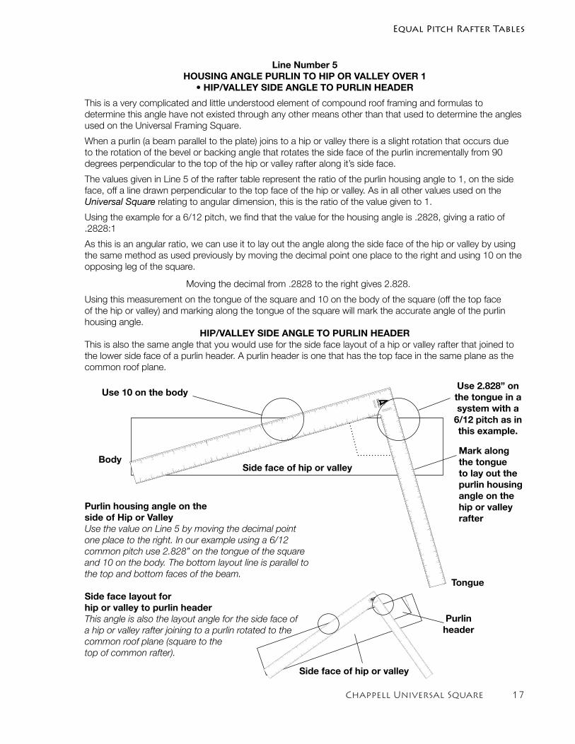
Line Number 5HOUSING ANGLE PURLIN TO HIP OR VALLEY OVER 1
• HIP/VALLEY SIDE ANGLE TO PURLIN HEADER
This is a very complicated and little understood element of compound roof framing and formulas to determine this angle have not existed through any other means other than that used to determine the angles used on the Universal Framing Square.
When a purlin (a beam parallel to the plate) joins to a hip or valley there is a slight rotation that occurs due to the rotation of the bevel or backing angle that rotates the side face of the purlin incrementally from 90 degrees perpendicular to the top of the hip or valley rafter along it’s side face.
The values given in Line 5 of the rafter table represent the ratio of the purlin housing angle to 1, on the side face, off a line drawn perpendicular to the top face of the hip or valley. As in all other values used on the Universal Square relating to angular dimension, this is the ratio of the value given to 1.
Using the example for a 6/12 pitch, we find that the value for the housing angle is .2828, giving a ratio of .2828:1
As this is an angular ratio, we can use it to lay out the angle along the side face of the hip or valley by using the same method as used previously by moving the decimal point one place to the right and using 10 on the opposing leg of the square.
Moving the decimal from .2828 to the right gives 2.828.
Using this measurement on the tongue of the square and 10 on the body of the square (off the top face of the hip or valley) and marking along the tongue of the square will mark the accurate angle of the purlin housing angle.
HIP/VALLEY SIDE ANGLE TO PURLIN HEADER This is also the same angle that you would use for the side face layout of a hip or valley rafter that joined to the lower side face of a purlin header. A purlin header is one that has the top face in the same plane as the common roof plane.
Purlin housing angle on the side of Hip or ValleyUse the value on Line 5 by moving the decimal point one place to the right. In our example using a 6/12 common pitch use 2.828” on the tongue of the square and 10 on the body. The bottom layout line is parallel to the top and bottom faces of the beam.
Side face layout for hip or valley to purlin headerThis angle is also the layout angle for the side face of a hip or valley rafter joining to a purlin rotated to the common roof plane (square to the top of common rafter).
Tongue
BodyMark along the tongue to lay out the purlin housing angle on the hip or valley rafter
Use 2.828” on the tongue in a system with a
6/12 pitch as in this example.
Use 10 on the body
CHAPPELL
UNEQUAL PITCHED
12/12 MAIN PITCH A
1
1
2
3
4
5
6
7
8
9
10
11
12
13
14
15
16
17
18
19
20
21
22
EQ
UA
L P
ITC
HE
D
RA
FTE
R T
AB
LE
2
3
4
5
6
7
8
9
10
11
12
13
14
15
16
17
1
2
3
4
5
6
7
8
9
10
11
12
13
14
15
1
2
3
4
5
6
7
8
9
10
11
12
13
14
15
16
17
18
19
20
21
22
23
CHAPPELL
UNEQ
UAL PIT
CHED
12/12 M
AIN P
ITC
H A
1
1
2
3
4
5
6
7
8
9
10
11
12
13
14
15
16
17
18
19
20
21
22
EQ
UAL P
ITC
HED
RAFTER T
ABLE
2
3
4
5
6
7
8
9
10
11
12
13
14
15
16
17
1
2
3
4
5
6
7
8
9
10
11
12
13
14
15
1
2
3
4
5
6
7
8
9
10
11
12
13
14
15
16
17
18
19
20
21
22
23
Purlin header
Side face of hip or valley
Side face of hip or valley
Equal Pitch Rafter Tables
1� Chappell Universal Square
CHAPPELL
UNEQUAL PITCHED
12/12 MAIN PITCH A
1
1
2
3
4
5
6
7
8
9
10
11
12
13
14
15
16
17
18
19
20
21
22
EQ
UAL P
ITC
HED
RAFTER T
ABLE
2
3
4
5
6
7
8
9
10
11
12
13
14
15
16
17
1
2
3
4
5
6
7
8
9
10
11
12
13
14
15
1
2
3
4
5
6
7
8
9
10
11
12
13
14
15
16
17
18
19
20
21
22
23
comm
on
rafte
r
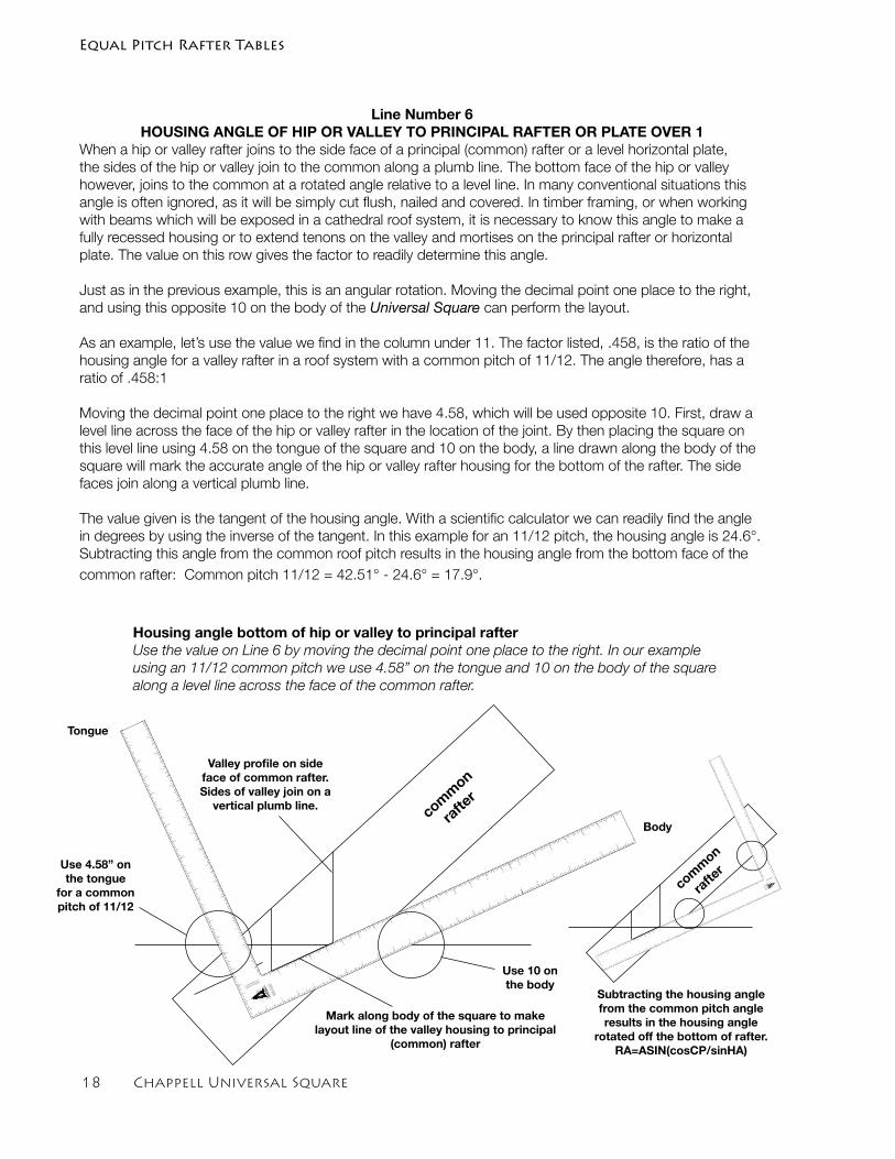
Line Number 6HOUSING ANGLE OF HIP OR VALLEY TO PRINCIPAL RAFTER OR PLATE OVER 1
When a hip or valley rafter joins to the side face of a principal (common) rafter or a level horizontal plate, the sides of the hip or valley join to the common along a plumb line. The bottom face of the hip or valley however, joins to the common at a rotated angle relative to a level line. In many conventional situations this angle is often ignored, as it will be simply cut flush, nailed and covered. In timber framing, or when working with beams which will be exposed in a cathedral roof system, it is necessary to know this angle to make a fully recessed housing or to extend tenons on the valley and mortises on the principal rafter or horizontal plate. The value on this row gives the factor to readily determine this angle.
Just as in the previous example, this is an angular rotation. Moving the decimal point one place to the right, and using this opposite 10 on the body of the Universal Square can perform the layout.
As an example, let’s use the value we find in the column under 11. The factor listed, .458, is the ratio of the housing angle for a valley rafter in a roof system with a common pitch of 11/12. The angle therefore, has a ratio of .458:1
Moving the decimal point one place to the right we have 4.58, which will be used opposite 10. First, draw a level line across the face of the hip or valley rafter in the location of the joint. By then placing the square on this level line using 4.58 on the tongue of the square and 10 on the body, a line drawn along the body of the square will mark the accurate angle of the hip or valley rafter housing for the bottom of the rafter. The side faces join along a vertical plumb line.
The value given is the tangent of the housing angle. With a scientific calculator we can readily find the angle in degrees by using the inverse of the tangent. In this example for an 11/12 pitch, the housing angle is 24.6°. Subtracting this angle from the common roof pitch results in the housing angle from the bottom face of the common rafter: Common pitch 11/12 = 42.51° - 24.6° = 17.9°.
Body
Mark along body of the square to make layout line of the valley housing to principal
(common) rafter
Use 4.58” on the tongue
for a common pitch of 11/12
Use 10 on the body
comm
on
rafte
r
CHAPPELL
UNEQUAL PITCHED
12/12 MAIN PITCH A
1
1
2
3
4
5
6
7
8
9
10
11
12
13
14
15
16
17
18
19
20
21
22
EQ
UAL P
ITC
HED
RA
FTER
TA
BLE2
3
4
5
6
7
8
9
10
11
12
13
14
15
16
17
1
2
3
4
5
6
7
8
9
10
11
12
13
14
15
1
2
3
4
5
6
7
8
9
10
11
12
13
14
15
16
17
18
19
20
21
22
23
Subtracting the housing angle from the common pitch angle results in the housing angle
rotated off the bottom of rafter.RA=ASIN(cosCP/sinHA)
Tongue
Valley profile on side face of common rafter. Sides of valley join on a
vertical plumb line.
Housing angle bottom of hip or valley to principal rafterUse the value on Line 6 by moving the decimal point one place to the right. In our example using an 11/12 common pitch we use 4.58” on the tongue and 10 on the body of the square along a level line across the face of the common rafter.
Equal Pitch Rafter Tables
Chappell Universal Square 1�
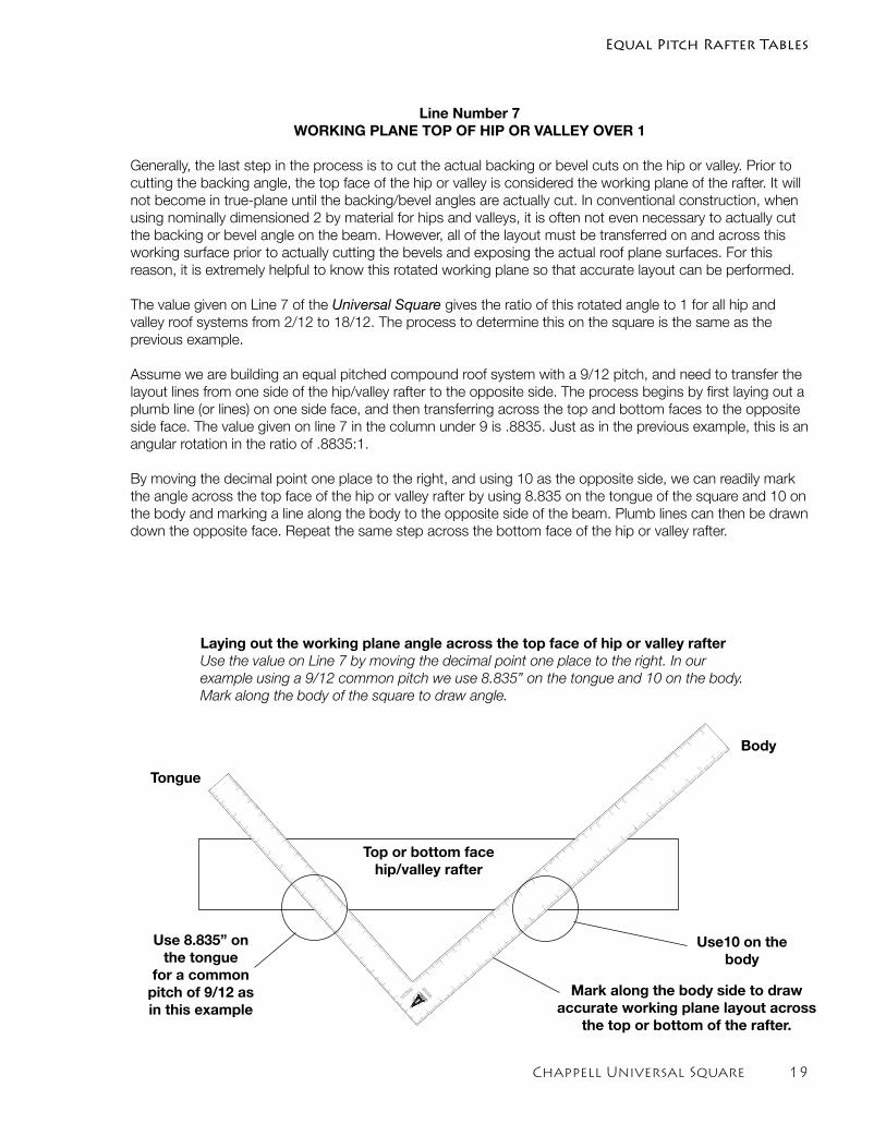
Line Number 7WORKING PLANE TOP OF HIP OR VALLEY OVER 1
Generally, the last step in the process is to cut the actual backing or bevel cuts on the hip or valley. Prior to cutting the backing angle, the top face of the hip or valley is considered the working plane of the rafter. It will not become in true-plane until the backing/bevel angles are actually cut. In conventional construction, when using nominally dimensioned 2 by material for hips and valleys, it is often not even necessary to actually cut the backing or bevel angle on the beam. However, all of the layout must be transferred on and across this working surface prior to actually cutting the bevels and exposing the actual roof plane surfaces. For this reason, it is extremely helpful to know this rotated working plane so that accurate layout can be performed.
The value given on Line 7 of the Universal Square gives the ratio of this rotated angle to 1 for all hip and valley roof systems from 2/12 to 18/12. The process to determine this on the square is the same as the previous example.
Assume we are building an equal pitched compound roof system with a 9/12 pitch, and need to transfer the layout lines from one side of the hip/valley rafter to the opposite side. The process begins by first laying out a plumb line (or lines) on one side face, and then transferring across the top and bottom faces to the opposite side face. The value given on line 7 in the column under 9 is .8835. Just as in the previous example, this is an angular rotation in the ratio of .8835:1.
By moving the decimal point one place to the right, and using 10 as the opposite side, we can readily mark the angle across the top face of the hip or valley rafter by using 8.835 on the tongue of the square and 10 on the body and marking a line along the body to the opposite side of the beam. Plumb lines can then be drawn down the opposite face. Repeat the same step across the bottom face of the hip or valley rafter.
CHAPPELL
UNEQ
UAL P
ITCHED
12/12 MAIN
PITC
H A
1
1
2
3
4
5
6
7
8
9
10
11
12
13
14
15
16
17
18
19
20
21
22
EQUAL P
ITCHED
RAFTER T
ABLE
2
3
4
5
6
7
8
9
10
11
12
13
14
15
16
17
1
2
3
4
5
6
7
8
9
10
11
12
13
14
15
1
2
3
4
5
6
7
8
9
10
11
12
13
14
15
16
17
18
19
20
21
22
23
Body
Tongue
Mark along the body side to draw accurate working plane layout across
the top or bottom of the rafter.
Laying out the working plane angle across the top face of hip or valley rafterUse the value on Line 7 by moving the decimal point one place to the right. In our example using a 9/12 common pitch we use 8.835” on the tongue and 10 on the body. Mark along the body of the square to draw angle.
Use 8.835” on the tongue
for a common pitch of 9/12 as in this example
Use10 on the body
Top or bottom face hip/valley rafter
Equal Pitch Rafter Tables
20 Chappell Universal Square
CHAPPELL
UNEQUAL PITCHED
12/12 MAIN PITCH A
1
1
2
3
4
5
6
7
8
9
10
11
12
13
14
15
16
17
18
19
20
21
22
EQ
UAL P
ITC
HED
RA
FTER
TA
BLE 2
3
4
5
6
7
8
9
10
11
12
13
14
15
16
17
1
2
3
4
5
6
7
8
9
10
11
12
13
14
15
1
2
3
4
5
6
7
8
9
10
11
12
13
14
15
16
17
18
19
20
21
22
23
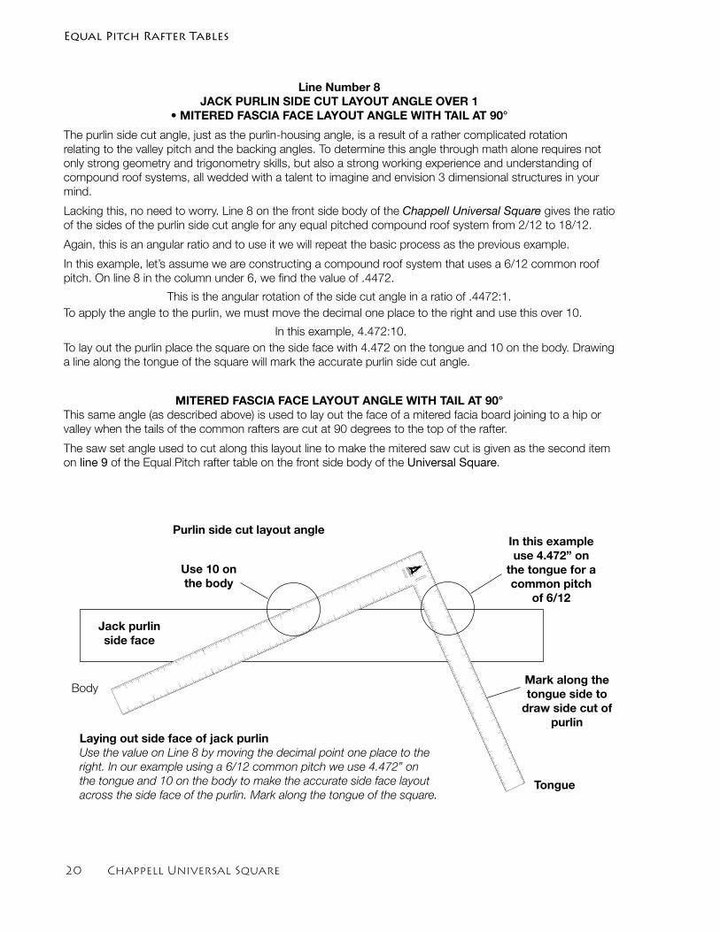
Line Number 8JACK PURLIN SIDE CUT LAYOUT ANGLE OVER 1
• MITERED FASCIA FACE LAYOUT ANGLE WITH TAIL AT 90°
The purlin side cut angle, just as the purlin-housing angle, is a result of a rather complicated rotation relating to the valley pitch and the backing angles. To determine this angle through math alone requires not only strong geometry and trigonometry skills, but also a strong working experience and understanding of compound roof systems, all wedded with a talent to imagine and envision 3 dimensional structures in your mind.
Lacking this, no need to worry. Line 8 on the front side body of the Chappell Universal Square gives the ratio of the sides of the purlin side cut angle for any equal pitched compound roof system from 2/12 to 18/12.
Again, this is an angular ratio and to use it we will repeat the basic process as the previous example.
In this example, let’s assume we are constructing a compound roof system that uses a 6/12 common roof pitch. On line 8 in the column under 6, we find the value of .4472.
This is the angular rotation of the side cut angle in a ratio of .4472:1.To apply the angle to the purlin, we must move the decimal one place to the right and use this over 10.
In this example, 4.472:10.To lay out the purlin place the square on the side face with 4.472 on the tongue and 10 on the body. Drawing a line along the tongue of the square will mark the accurate purlin side cut angle.
MITERED FASCIA FACE LAYOUT ANGLE WITH TAIL AT 90°This same angle (as described above) is used to lay out the face of a mitered facia board joining to a hip or valley when the tails of the common rafters are cut at 90 degrees to the top of the rafter.
The saw set angle used to cut along this layout line to make the mitered saw cut is given as the second item on line 9 of the Equal Pitch rafter table on the front side body of the Universal Square.
Body
Tongue
Mark along the tongue side to
draw side cut of purlin
In this example use 4.472” on
the tongue for a common pitch
of 6/12
Use 10 on the body
Jack purlin side face
Laying out side face of jack purlinUse the value on Line 8 by moving the decimal point one place to the right. In our example using a 6/12 common pitch we use 4.472” on the tongue and 10 on the body to make the accurate side face layout across the side face of the purlin. Mark along the tongue of the square.
Purlin side cut layout angle
Equal Pitch Rafter Tables
Chappell Universal Square 21
Line Number 91) HIP OR VALLEY BACKING & BEVEL ANGLE • JACK RAFTER AND PURLIN TOP CUT SAW ANGLE
2) FASCIA MITER SAW CUT ANGLE TAILS AT 90 DEGREES
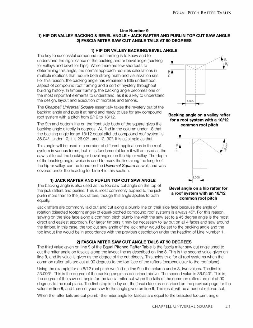
1) HIP OR VALLEY BACKING/BEVEL ANGLEThe key to successful compound roof framing is to know and to understand the significance of the backing and or bevel angle (backing for valleys and bevel for hips). While there are few shortcuts to determining this angle, the normal approach requires calculations in multiple rotations that require both strong math and visualization sills. For this reason, the backing angle has remained a little understood aspect of compound roof framing and a sort of mystery throughout building history. In timber framing, the backing angle becomes one of the most important elements to understand, as it is a key to understand the design, layout and execution of mortises and tenons.
The Chappell Universal Square essentially takes the mystery out of the backing angle and puts it at hand and ready to use for any compound roof system with a pitch from 2/12 to 18/12.
The 9th and bottom line on the front side body of the square gives the backing angle directly in degrees. We find in the column under 18 that the backing angle for an 18/12 equal pitched compound roof system is 36.04°. Under 10, it is 26.92°, and 12, 30°. It is as simple as that.
This angle will be used in a number of different applications in the roof system in various forms, but in its fundamental form it will be used as the saw set to cut the backing or bevel angles on the hip or valley. The depth of the backing angle, which is used to mark the line along the length of the hip or valley, can be found on the Universal Square as well, and was covered under the heading for Line 4 in this section.
1) JACK RAFTER AND PURLIN TOP CUT SAW ANGLEThe backing angle is also used as the top saw cut angle on the top of the jack rafters and purlins. This is most commonly applied to the jack purlin more than to the jack rafters, though this angle applies to both equally.
Jack rafters are commonly laid out and cut along a plumb line on their side face because the angle of rotation (bisected footprint angle) of equal-pitched compound roof systems is always 45°. For this reason, sawing on the side face along a common pitch plumb line with the saw set to a 45 degree angle is the most direct and easiest approach. For larger timbers it may be necessary to lay out on all 4 faces and saw around the timber. In this case, the top cut saw angle of the jack rafter would be set to the backing angle and the top layout line would be in accordance with the previous description under the heading of Line Number 1.
2) FASCIA MITER SAW CUT ANGLE TAILS AT 90 DEGREESThe third value given on line 9 of the Equal Pitched Rafter Table is the fascia miter saw cut angle used to cut the miter angle on fascias along the layout line as described on line 8. This is the second value given on line 9, and its value is given as the degree of the cut directly. This holds true for all roof systems when the common rafter tails are cut at 90 degrees to the top face of the rafters (perpendicular to the roof plane).
Using the example for an 8/12 roof pitch we find on line 9 in the column under 8, two values. The first is 23.093°. This is the degree of the backing angle as described above. The second value is 36.040°. This is the degree of the saw cut angle for the fascia miter cut when the tails of the common rafters are cut at 90 degrees to the roof plane. The first step is to lay out the fascia face as described on the previous page for the value on line 8, and then set your saw to the angle given on line 9. The result will be a perfect mitered cut.
When the rafter tails are cut plumb, the miter angle for fascias are equal to the bisected footprint angle.
Backing angle on a valley rafter for a roof system with a 10/12
common roof pitch
4.0003.000
2.183
2.031
26.92°
36.04°
Bevel angle on a hip rafter for a roof system with an 18/12
common roof pitch
Equal Pitch Rafter Tables
4.0003.000
2.183
2.031
26.92°
36.04°
22 Chappell Universal Square
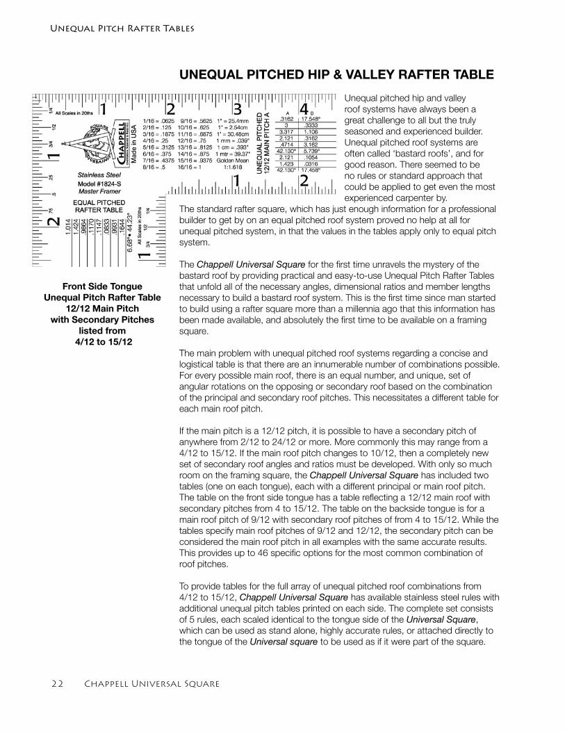
UNEQUAL PITCHED HIP & VALLEY RAFTER TABLE
Unequal pitched hip and valley roof systems have always been a great challenge to all but the truly seasoned and experienced builder. Unequal pitched roof systems are often called ‘bastard roofs’, and for good reason. There seemed to be no rules or standard approach that could be applied to get even the most experienced carpenter by.
The standard rafter square, which has just enough information for a professional builder to get by on an equal pitched roof system proved no help at all for unequal pitched system, in that the values in the tables apply only to equal pitch system.
The Chappell Universal Square for the first time unravels the mystery of the bastard roof by providing practical and easy-to-use Unequal Pitch Rafter Tables that unfold all of the necessary angles, dimensional ratios and member lengths necessary to build a bastard roof system. This is the first time since man started to build using a rafter square more than a millennia ago that this information has been made available, and absolutely the first time to be available on a framing square.
The main problem with unequal pitched roof systems regarding a concise and logistical table is that there are an innumerable number of combinations possible. For every possible main roof, there is an equal number, and unique, set of angular rotations on the opposing or secondary roof based on the combination of the principal and secondary roof pitches. This necessitates a different table for each main roof pitch.
If the main pitch is a 12/12 pitch, it is possible to have a secondary pitch of anywhere from 2/12 to 24/12 or more. More commonly this may range from a 4/12 to 15/12. If the main roof pitch changes to 10/12, then a completely new set of secondary roof angles and ratios must be developed. With only so much room on the framing square, the Chappell Universal Square has included two tables (one on each tongue), each with a different principal or main roof pitch. The table on the front side tongue has a table reflecting a 12/12 main roof with secondary pitches from 4 to 15/12. The table on the backside tongue is for a main roof pitch of 9/12 with secondary roof pitches of from 4 to 15/12. While the tables specify main roof pitches of 9/12 and 12/12, the secondary pitch can be considered the main roof pitch in all examples with the same accurate results. This provides up to 46 specific options for the most common combination of roof pitches.
To provide tables for the full array of unequal pitched roof combinations from 4/12 to 15/12, Chappell Universal Square has available stainless steel rules with additional unequal pitch tables printed on each side. The complete set consists of 5 rules, each scaled identical to the tongue side of the Universal Square, which can be used as stand alone, highly accurate rules, or attached directly to the tongue of the Universal square to be used as if it were part of the square.
Front Side TongueUnequal Pitch Rafter Table
12/12 Main Pitch with Secondary Pitches
listed from 4/12 to 15/12
Unequal Pitch Rafter Tables
Chappell Universal Square 2�
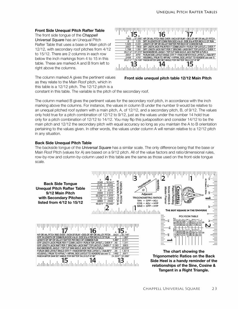
Front Side Unequal Pitch Rafter TableThe front side tongue of the Chappell Universal Square has an Unequal Pitch Rafter Table that uses a base or Main pitch of 12/12, with secondary roof pitches from 4/12 to 15/12. There are 2 columns in each row below the inch markings from 4 to 15 in this table. These are marked A and B from left to right above the columns.
The column marked A gives the pertinent values as they relate to the Main Roof pitch, which in this table is a 12/12 pitch. The 12/12 pitch is a constant in this table. The variable is the pitch of the secondary roof.
The column marked B gives the pertinent values for the secondary roof pitch, in accordance with the inch marking above the columns. For instance, the values in column B under the number 9 would be relative to an unequal pitched roof system with a main pitch, A, of 12/12, and a secondary pitch, B, of 9/12. The values only hold true for a pitch combination of 12/12 to 9/12, just as the values under the number 14 hold true only for a pitch combination of 12/12 to 14/12. You may flip this juxtaposition and consider 14/12 to be the main pitch and 12/12 the secondary pitch with equal accuracy so long as you maintain the A to B orientation pertaining to the values given. In other words, the values under column A will remain relative to a 12/12 pitch in any situation.
Back Side Unequal Pitch TableThe backside tongue of the Universal Square has a similar scale. The only difference being that the base or Main Roof Pitch (values for A) are based on a 9/12 pitch. All of the value factors and ratio/dimensional rules, row-by-row and column-by-column used in this table are the same as those used on the front-side tongue scale.
Back Side TongueUnequal Pitch Rafter Table
9/12 Main Pitchwith Secondary Pitches listed from 4/12 to 15/12
Unequal Pitch Rafter Tables
Front side unequal pitch table 12/12 Main Pitch
The chart showing the Trigonometric Ratios on the Back
Side Heel is a handy reminder of the relationships of the Sine, Cosine &
Tangent in a Right Triangle.
2� Chappell Universal Square
Line 1HIP OR VALLEY PITCH INCHES OF RISE OVER 1 INCH RUN
• DEGREE OF HIP OR VALLEY PITCH
HIP OR VALLEY PITCH INCHES RISE OVER 1 INCH RUNWhen working with equal pitched roofs, the angle of the hip or valley pitch is a simple step. Simply use the inches of rise per foot of run over 16.97 instead of 12 and you have the valley level and plumb cuts. The tangent of this angle can also easily be determined by dividing the inches of rise by 16.97. Knowing the tangent, one can quickly determine the angle of the pitch in degrees on a pocket scientific calculator. Ready to move forward in a few moments.
Working with unequal pitches however is a completely different process and many a carpenter have a bald spot above their right ear from scratching their head in wonder just how to calculate this pitch. The Universal Square for the first time solves this perplexing problem and within moments virtually anyone with only rudimentary math and or building skills can begin to layout an unequal pitched roof system with the Chappell Universal Square.
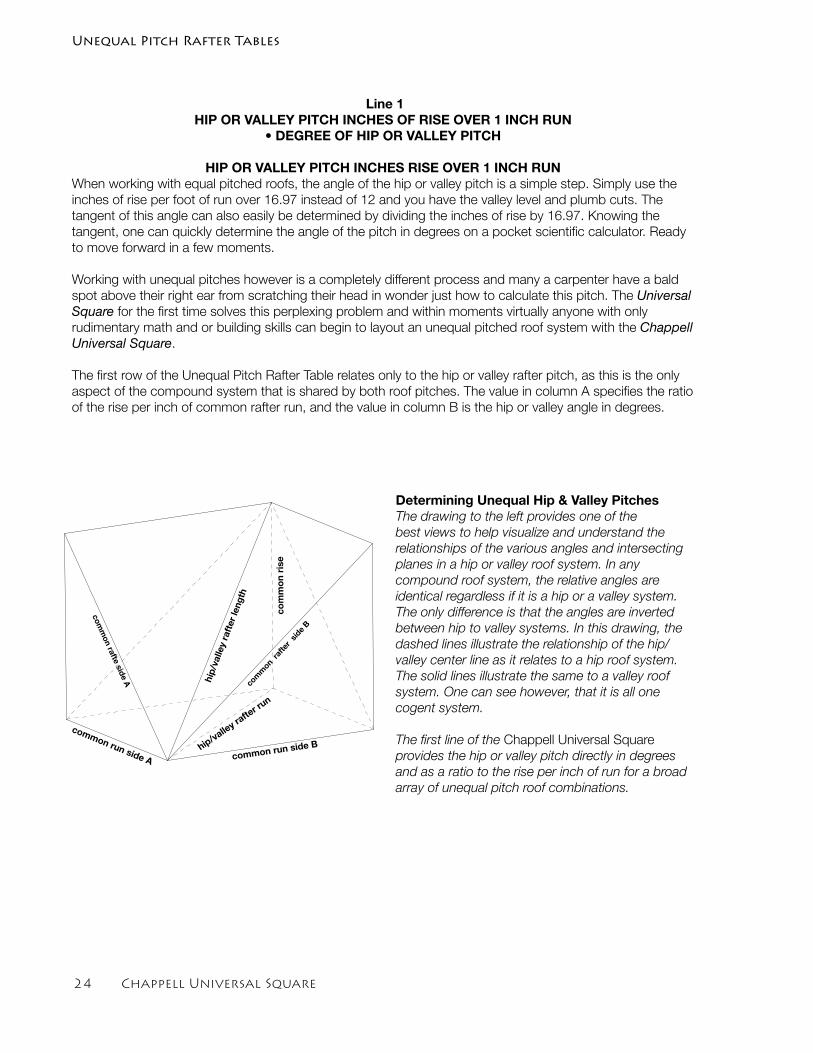
The first row of the Unequal Pitch Rafter Table relates only to the hip or valley rafter pitch, as this is the only aspect of the compound system that is shared by both roof pitches. The value in column A specifies the ratio of the rise per inch of common rafter run, and the value in column B is the hip or valley angle in degrees.
common run side B
common run side Ahip/valle
y rafte
r run
hip/
valle
y ra
fter
leng
th
Determining Unequal Hip & Valley PitchesThe drawing to the left provides one of the best views to help visualize and understand the relationships of the various angles and intersecting planes in a hip or valley roof system. In any compound roof system, the relative angles are identical regardless if it is a hip or a valley system. The only difference is that the angles are inverted between hip to valley systems. In this drawing, the dashed lines illustrate the relationship of the hip/valley center line as it relates to a hip roof system. The solid lines illustrate the same to a valley roof system. One can see however, that it is all one cogent system.
The first line of the Chappell Universal Square provides the hip or valley pitch directly in degrees and as a ratio to the rise per inch of run for a broad array of unequal pitch roof combinations.
com
mon
rafte
r sid
e B
comm
on rafte side A
com
mo
n ri
se
Unequal Pitch Rafter Tables
Chappell Universal Square 2�
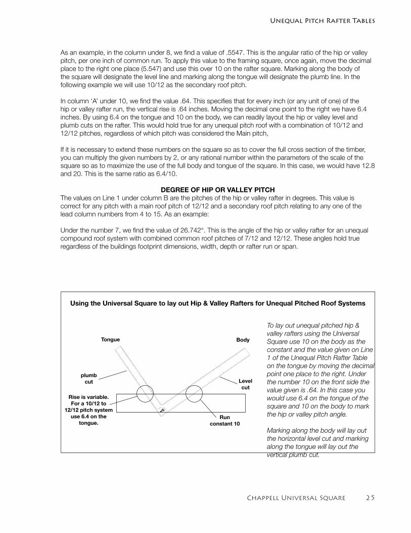
As an example, in the column under 8, we find a value of .5547. This is the angular ratio of the hip or valley pitch, per one inch of common run. To apply this value to the framing square, once again, move the decimal place to the right one place (5.547) and use this over 10 on the rafter square. Marking along the body of the square will designate the level line and marking along the tongue will designate the plumb line. In the following example we will use 10/12 as the secondary roof pitch.
In column ‘A’ under 10, we find the value .64. This specifies that for every inch (or any unit of one) of the hip or valley rafter run, the vertical rise is .64 inches. Moving the decimal one point to the right we have 6.4 inches. By using 6.4 on the tongue and 10 on the body, we can readily layout the hip or valley level and plumb cuts on the rafter. This would hold true for any unequal pitch roof with a combination of 10/12 and 12/12 pitches, regardless of which pitch was considered the Main pitch,
If it is necessary to extend these numbers on the square so as to cover the full cross section of the timber, you can multiply the given numbers by 2, or any rational number within the parameters of the scale of the square so as to maximize the use of the full body and tongue of the square. In this case, we would have 12.8 and 20. This is the same ratio as 6.4/10.
DEGREE OF HIP OR VALLEY PITCHThe values on Line 1 under column B are the pitches of the hip or valley rafter in degrees. This value is correct for any pitch with a main roof pitch of 12/12 and a secondary roof pitch relating to any one of the lead column numbers from 4 to 15. As an example:
Under the number 7, we find the value of 26.742°. This is the angle of the hip or valley rafter for an unequal compound roof system with combined common roof pitches of 7/12 and 12/12. These angles hold true regardless of the buildings footprint dimensions, width, depth or rafter run or span.
CHAPPELL
UNEQUAL PITCHED
12/12 MAIN
PITCH
A
1
1
2
3
4
5
6
7
8
9
10
11
12
13
14
15
16
17
18
19
20
21
22
EQ
UAL P
ITC
HED
RAFTER T
ABLE
2
3
4
5
6
7
8
9
10
11
12
13
14
15
16
17
1
2
3
4
5
6
7
8
9
10
11
12
13
14
15
1
2
3
4
5
6
7
8
9
10
11
12
13
14
15
16
17
18
19
20
21
22
23
To lay out unequal pitched hip & valley rafters using the Universal Square use 10 on the body as the constant and the value given on Line 1 of the Unequal Pitch Rafter Table on the tongue by moving the decimal point one place to the right. Under the number 10 on the front side the value given is .64. In this case you would use 6.4 on the tongue of the square and 10 on the body to mark the hip or valley pitch angle.
Marking along the body will lay out the horizontal level cut and marking along the tongue will lay out the vertical plumb cut.
BodyTongue
Level cut
plumbcut
Run constant 10
Rise is variable. For a 10/12 to
12/12 pitch systemuse 6.4 on the
tongue.
Using the Universal Square to lay out Hip & Valley Rafters for Unequal Pitched Roof Systems
Unequal Pitch Rafter Tables
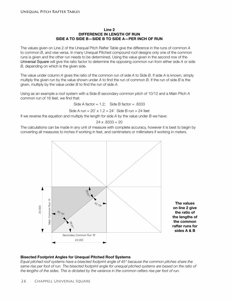
2� Chappell Universal Square
Line 2DIFFERENCE IN LENGTH OF RUN
SIDE A TO SIDE B—SIDE B TO SIDE A—PER INCH OF RUN
The values given on Line 2 of the Unequal Pitch Rafter Table give the difference in the runs of common A to common B, and vise versa. In many Unequal Pitched compound roof designs only one of the common runs is given and the other run needs to be determined. Using the value given in the second row of the Universal Square will give the ratio factor to determine the opposing common run from either side A or side B, depending on which is the given side.
The value under column A gives the ratio of the common run of side A to Side B. If side A is known, simply multiply the given run by the value shown under A to find the run of common B. If the run of side B is the given, multiply by the value under B to find the run of side A.
Using as an example a roof system with a Side B secondary common pitch of 10/12 and a Main Pitch A common run of 16 feet, we find that:
Side A factor = 1.2; Side B factor = .8333
Side A run = 20’ x 1.2 = 24’ Side B run = 24 feet If we reverse the equation and multiply the length for side A by the value under B we have:
24 x .8333 = 20The calculations can be made in any unit of measure with complete accuracy, however it is best to begin by converting all measures to inches if working in feet, and centimeters or millimeters if working in meters.
Secondary Common Run 'B'
Main
Com
mon R
un 'A
'
20
.00
0
24.000
39.81°
50.19°
39.81°
50.19°
Bisected Footprint Angles for Unequal Pitched Roof Systems Equal pitched roof systems have a bisected footprint angle of 45° because the common pitches share the same rise per foot of run. The bisected footprint angle for unequal pitched systems are based on the ratio of the lengths of the sides. This is dictated by the variance in the common rafters rise per foot of run.
The values on line 2 give the ratio of
the lengths of the common
rafter runs for sides A & B
Unequal Pitch Rafter Tables
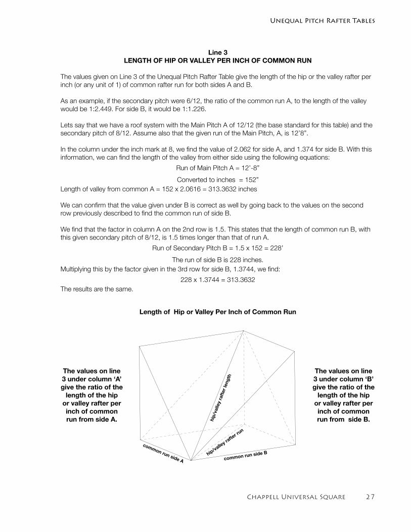
Chappell Universal Square 2�
Line 3LENGTH OF HIP OR VALLEY PER INCH OF COMMON RUN
The values given on Line 3 of the Unequal Pitch Rafter Table give the length of the hip or the valley rafter per inch (or any unit of 1) of common rafter run for both sides A and B.
As an example, if the secondary pitch were 6/12, the ratio of the common run A, to the length of the valley would be 1:2.449. For side B, it would be 1:1.226.
Lets say that we have a roof system with the Main Pitch A of 12/12 (the base standard for this table) and the secondary pitch of 8/12. Assume also that the given run of the Main Pitch, A, is 12’8”.
In the column under the inch mark at 8, we find the value of 2.062 for side A, and 1.374 for side B. With this information, we can find the length of the valley from either side using the following equations:
Run of Main Pitch A = 12’-8”
Converted to inches = 152”Length of valley from common A = 152 x 2.0616 = 313.3632 inches
We can confirm that the value given under B is correct as well by going back to the values on the second row previously described to find the common run of side B.
We find that the factor in column A on the 2nd row is 1.5. This states that the length of common run B, with this given secondary pitch of 8/12, is 1.5 times longer than that of run A.
Run of Secondary Pitch B = 1.5 x 152 = 228’
The run of side B is 228 inches.Multiplying this by the factor given in the 3rd row for side B, 1.3744, we find:
228 x 1.3744 = 313.3632The results are the same.
Length of Hip or Valley Per Inch of Common Run
The values on line 3 under column ‘B’ give the ratio of the
length of the hip or valley rafter per inch of common run from side B.
The values on line 3 under column ‘A’ give the ratio of the
length of the hip or valley rafter per inch of common run from side A.
common run side B
common run side Ahip/valle
y rafte
r run
hip/
valle
y ra
fter
leng
th
Unequal Pitch Rafter Tables
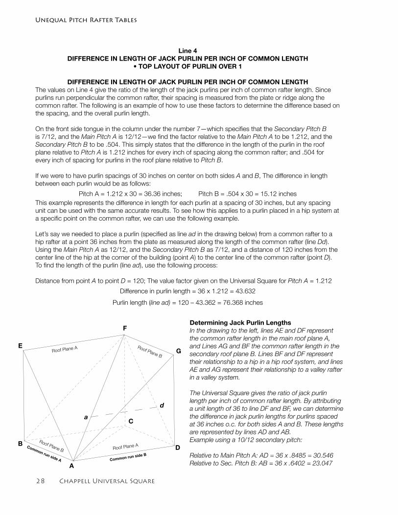
2� Chappell Universal Square
Line 4DIFFERENCE IN LENGTH OF JACK PURLIN PER INCH OF COMMON LENGTH
• TOP LAYOUT OF PURLIN OVER 1
DIFFERENCE IN LENGTH OF JACK PURLIN PER INCH OF COMMON LENGTHThe values on Line 4 give the ratio of the length of the jack purlins per inch of common rafter length. Since purlins run perpendicular the common rafter, their spacing is measured from the plate or ridge along the common rafter. The following is an example of how to use these factors to determine the difference based on the spacing, and the overall purlin length.
On the front side tongue in the column under the number 7—which specifies that the Secondary Pitch B is 7/12, and the Main Pitch A is 12/12—we find the factor relative to the Main Pitch A to be 1.212, and the Secondary Pitch B to be .504. This simply states that the difference in the length of the purlin in the roof plane relative to Pitch A is 1.212 inches for every inch of spacing along the common rafter; and .504 for every inch of spacing for purlins in the roof plane relative to Pitch B.
If we were to have purlin spacings of 30 inches on center on both sides A and B, The difference in length between each purlin would be as follows:
Pitch A = 1.212 x 30 = 36.36 inches; Pitch B = .504 x 30 = 15.12 inchesThis example represents the difference in length for each purlin at a spacing of 30 inches, but any spacing unit can be used with the same accurate results. To see how this applies to a purlin placed in a hip system at a specific point on the common rafter, we can use the following example.
Let’s say we needed to place a purlin (specified as line ad in the drawing below) from a common rafter to a hip rafter at a point 36 inches from the plate as measured along the length of the common rafter (line Dd). Using the Main Pitch A as 12/12, and the Secondary Pitch B as 7/12, and a distance of 120 inches from the center line of the hip at the corner of the building (point A) to the center line of the common rafter (point D). To find the length of the purlin (line ad), use the following process:
Distance from point A to point D = 120; The value factor given on the Universal Square for Pitch A = 1.212
Difference in purlin length = 36 x 1.212 = 43.632
Purlin length (line ad) = 120 – 43.362 = 76.368 inches
Determining Jack Purlin LengthsIn the drawing to the left, lines AE and DF represent the common rafter length in the main roof plane A, and Lines AG and BF the common rafter length in the secondary roof plane B. Lines BF and DF represent their relationship to a hip in a hip roof system, and lines AE and AG represent their relationship to a valley rafter in a valley system.
The Universal Square gives the ratio of jack purlin length per inch of common rafter length. By attributing a unit length of 36 to line DF and BF, we can determine the difference in jack purlin lengths for purlins spaced at 36 inches o.c. for both sides A and B. These lengths are represented by lines AD and AB.Example using a 10/12 secondary pitch:
Relative to Main Pitch A: AD = 36 x .8485 = 30.546Relative to Sec. Pitch B: AB = 36 x .6402 = 23.047A
B
C
D
E
F
G
Common run side B
Common run side A
d
a
Unequal Pitch Rafter Tables
Roof Plane A Roof Plane B
Roof Plane ARoof Plane B
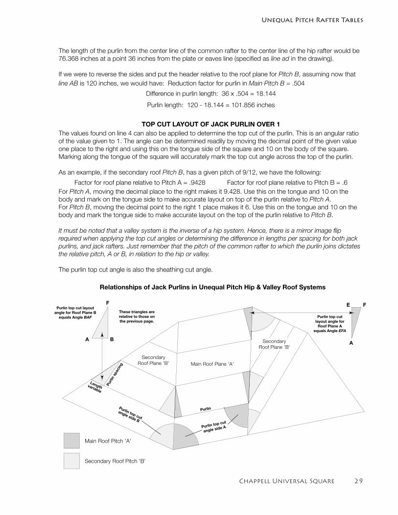
Chappell Universal Square 2�
The length of the purlin from the center line of the common rafter to the center line of the hip rafter would be 76.368 inches at a point 36 inches from the plate or eaves line (specified as line ad in the drawing).
If we were to reverse the sides and put the header relative to the roof plane for Pitch B, assuming now that line AB is 120 inches, we would have: Reduction factor for purlin in Main Pitch B = .504
Difference in purlin length: 36 x .504 = 18.144
Purlin length: 120 - 18.144 = 101.856 inches
TOP CUT LAYOUT OF JACK PURLIN OVER 1The values found on line 4 can also be applied to determine the top cut of the purlin. This is an angular ratio of the value given to 1. The angle can be determined readily by moving the decimal point of the given value one place to the right and using this on the tongue side of the square and 10 on the body of the square. Marking along the tongue of the square will accurately mark the top cut angle across the top of the purlin.
As an example, if the secondary roof Pitch B, has a given pitch of 9/12, we have the following:
Factor for roof plane relative to Pitch A = .9428 Factor for roof plane relative to Pitch B = .6For Pitch A, moving the decimal place to the right makes it 9.428. Use this on the tongue and 10 on the body and mark on the tongue side to make accurate layout on top of the purlin relative to Pitch A.For Pitch B, moving the decimal point to the right 1 place makes it 6. Use this on the tongue and 10 on the body and mark the tongue side to make accurate layout on the top of the purlin relative to Pitch B.
It must be noted that a valley system is the inverse of a hip system. Hence, there is a mirror image flip required when applying the top cut angles or determining the difference in lengths per spacing for both jack purlins, and jack rafters. Just remember that the pitch of the common rafter to which the purlin joins dictates the relative pitch, A or B, in relation to the hip or valley.
The purlin top cut angle is also the sheathing cut angle.
Unequal Pitch Rafter Tables
Relationships of Jack Purlins in Unequal Pitch Hip & Valley Roof Systems
Main Roof Pitch 'A'
Secondary Roof Pitch 'B'
Main Roof Plane 'A'
Secondary
Roof Plane 'B'
Secondary
Roof Plane 'B'
F
BA
F
A
EThese triangles are relative to those on the previous page.
Purli
n sp
acin
g
Lengthvariable
PurlinPurlin top cut
angle side B
Purlin top cut
angle side A
Purlin top cut layout angle for Roof Plane B
equals Angle BAF Purlin top cut layout angle for
Roof Plane A equals Angle EFA
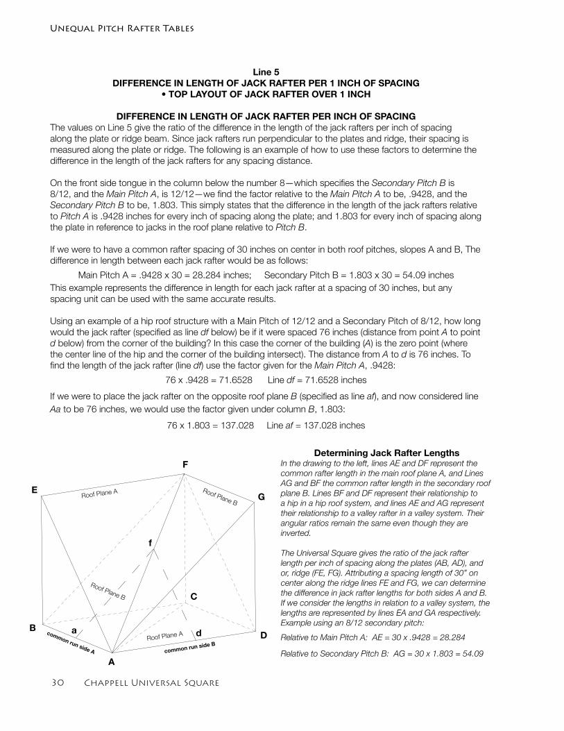
�0 Chappell Universal Square
Line 5DIFFERENCE IN LENGTH OF JACK RAFTER PER 1 INCH OF SPACING
• TOP LAYOUT OF JACK RAFTER OVER 1 INCH
DIFFERENCE IN LENGTH OF JACK RAFTER PER INCH OF SPACINGThe values on Line 5 give the ratio of the difference in the length of the jack rafters per inch of spacing along the plate or ridge beam. Since jack rafters run perpendicular to the plates and ridge, their spacing is measured along the plate or ridge. The following is an example of how to use these factors to determine the difference in the length of the jack rafters for any spacing distance.
On the front side tongue in the column below the number 8—which specifies the Secondary Pitch B is 8/12, and the Main Pitch A, is 12/12—we find the factor relative to the Main Pitch A to be, .9428, and the Secondary Pitch B to be, 1.803. This simply states that the difference in the length of the jack rafters relative to Pitch A is .9428 inches for every inch of spacing along the plate; and 1.803 for every inch of spacing along the plate in reference to jacks in the roof plane relative to Pitch B.
If we were to have a common rafter spacing of 30 inches on center in both roof pitches, slopes A and B, The difference in length between each jack rafter would be as follows:
Main Pitch A = .9428 x 30 = 28.284 inches; Secondary Pitch B = 1.803 x 30 = 54.09 inchesThis example represents the difference in length for each jack rafter at a spacing of 30 inches, but any spacing unit can be used with the same accurate results.
Using an example of a hip roof structure with a Main Pitch of 12/12 and a Secondary Pitch of 8/12, how long would the jack rafter (specified as line df below) be if it were spaced 76 inches (distance from point A to point d below) from the corner of the building? In this case the corner of the building (A) is the zero point (where the center line of the hip and the corner of the building intersect). The distance from A to d is 76 inches. To find the length of the jack rafter (line df) use the factor given for the Main Pitch A, .9428:
76 x .9428 = 71.6528 Line df = 71.6528 inches
If we were to place the jack rafter on the opposite roof plane B (specified as line af), and now considered line Aa to be 76 inches, we would use the factor given under column B, 1.803:
76 x 1.803 = 137.028 Line af = 137.028 inches
Determining Jack Rafter LengthsIn the drawing to the left, lines AE and DF represent the common rafter length in the main roof plane A, and Lines AG and BF the common rafter length in the secondary roof plane B. Lines BF and DF represent their relationship to a hip in a hip roof system, and lines AE and AG represent their relationship to a valley rafter in a valley system. Their angular ratios remain the same even though they are inverted.
The Universal Square gives the ratio of the jack rafter length per inch of spacing along the plates (AB, AD), and or, ridge (FE, FG). Attributing a spacing length of 30” on center along the ridge lines FE and FG, we can determine the difference in jack rafter lengths for both sides A and B. If we consider the lengths in relation to a valley system, the lengths are represented by lines EA and GA respectively.Example using an 8/12 secondary pitch:
Relative to Main Pitch A: AE = 30 x .9428 = 28.284
Relative to Secondary Pitch B: AG = 30 x 1.803 = 54.09A
B
C
D
E
F
G
common run side B
common run side A
d
f
a
Unequal Pitch Rafter Tables
Roof Plane A Roof Plane B
Roof Plane A
Roof Plane B
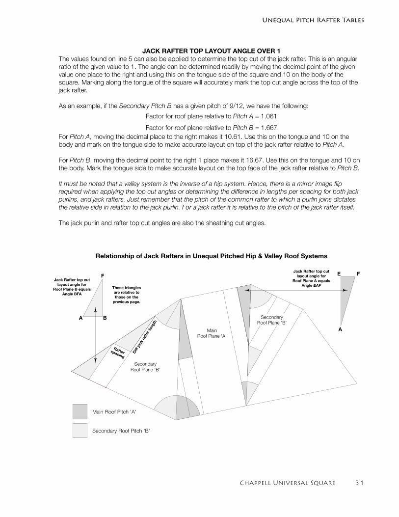
Chappell Universal Square �1
JACK RAFTER TOP LAYOUT ANGLE OVER 1The values found on line 5 can also be applied to determine the top cut of the jack rafter. This is an angular ratio of the given value to 1. The angle can be determined readily by moving the decimal point of the given value one place to the right and using this on the tongue side of the square and 10 on the body of the square. Marking along the tongue of the square will accurately mark the top cut angle across the top of the jack rafter.
As an example, if the Secondary Pitch B has a given pitch of 9/12, we have the following:
Factor for roof plane relative to Pitch A = 1.061
Factor for roof plane relative to Pitch B = 1.667For Pitch A, moving the decimal place to the right makes it 10.61. Use this on the tongue and 10 on the body and mark on the tongue side to make accurate layout on top of the jack rafter relative to Pitch A.
For Pitch B, moving the decimal point to the right 1 place makes it 16.67. Use this on the tongue and 10 on the body. Mark the tongue side to make accurate layout on the top face of the jack rafter relative to Pitch B.
It must be noted that a valley system is the inverse of a hip system. Hence, there is a mirror image flip required when applying the top cut angles or determining the difference in lengths per spacing for both jack purlins, and jack rafters. Just remember that the pitch of the common rafter to which a purlin joins dictates the relative side in relation to the jack purlin. For a jack rafter it is relative to the pitch of the jack rafter itself.
The jack purlin and rafter top cut angles are also the sheathing cut angles.
Main Roof Pitch 'A'
Secondary Roof Pitch 'B'
Main
Roof Plane 'A'
Secondary
Roof Plane 'B'
Secondary
Roof Plane 'B'
Relationship of Jack Rafters in Unequal Pitched Hip & Valley Roof Systems
These triangles are relative to those on the
previous page.
Diff
jack
rafte
r len
gth
Rafterspacing
F
BA
F
A
E
Unequal Pitch Rafter Tables
Jack Rafter top cut layout angle for
Roof Plane B equals Angle BFA
Jack Rafter top cut layout angle for
Roof Plane A equals Angle EAF
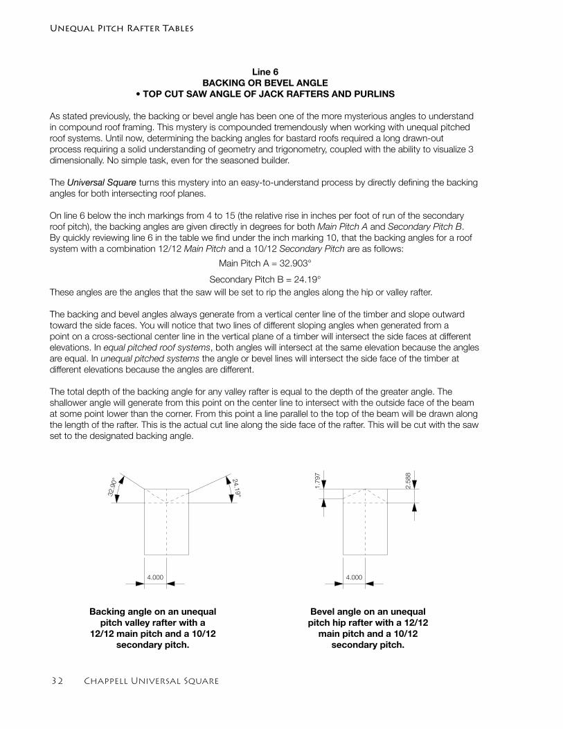
�2 Chappell Universal Square
Line 6BACKING OR BEVEL ANGLE
• TOP CUT SAW ANGLE OF JACK RAFTERS AND PURLINS
As stated previously, the backing or bevel angle has been one of the more mysterious angles to understand in compound roof framing. This mystery is compounded tremendously when working with unequal pitched roof systems. Until now, determining the backing angles for bastard roofs required a long drawn-out process requiring a solid understanding of geometry and trigonometry, coupled with the ability to visualize 3 dimensionally. No simple task, even for the seasoned builder.
The Universal Square turns this mystery into an easy-to-understand process by directly defining the backing angles for both intersecting roof planes.
On line 6 below the inch markings from 4 to 15 (the relative rise in inches per foot of run of the secondary roof pitch), the backing angles are given directly in degrees for both Main Pitch A and Secondary Pitch B. By quickly reviewing line 6 in the table we find under the inch marking 10, that the backing angles for a roof system with a combination 12/12 Main Pitch and a 10/12 Secondary Pitch are as follows:
Main Pitch A = 32.903°
Secondary Pitch B = 24.19°These angles are the angles that the saw will be set to rip the angles along the hip or valley rafter.
The backing and bevel angles always generate from a vertical center line of the timber and slope outward toward the side faces. You will notice that two lines of different sloping angles when generated from a point on a cross-sectional center line in the vertical plane of a timber will intersect the side faces at different elevations. In equal pitched roof systems, both angles will intersect at the same elevation because the angles are equal. In unequal pitched systems the angle or bevel lines will intersect the side face of the timber at different elevations because the angles are different.
The total depth of the backing angle for any valley rafter is equal to the depth of the greater angle. The shallower angle will generate from this point on the center line to intersect with the outside face of the beam at some point lower than the corner. From this point a line parallel to the top of the beam will be drawn along the length of the rafter. This is the actual cut line along the side face of the rafter. This will be cut with the saw set to the designated backing angle.
32.90° 2
4.19°
2.5
88
1.7
97
4.0004.000
Backing angle on an unequal pitch valley rafter with a
12/12 main pitch and a 10/12 secondary pitch.
Bevel angle on an unequal pitch hip rafter with a 12/12
main pitch and a 10/12 secondary pitch.
Unequal Pitch Rafter Tables
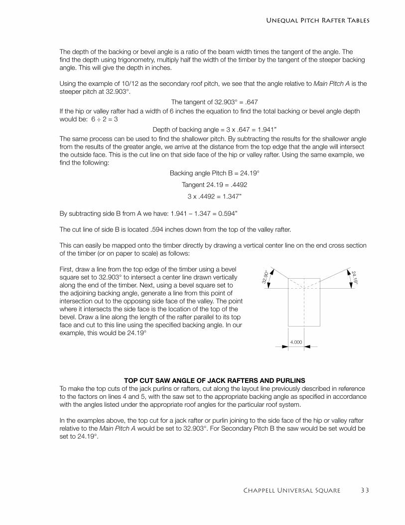
Chappell Universal Square ��
The depth of the backing or bevel angle is a ratio of the beam width times the tangent of the angle. The find the depth using trigonometry, multiply half the width of the timber by the tangent of the steeper backing angle. This will give the depth in inches.
Using the example of 10/12 as the secondary roof pitch, we see that the angle relative to Main Pitch A is the steeper pitch at 32.903°.
The tangent of 32.903° = .647If the hip or valley rafter had a width of 6 inches the equation to find the total backing or bevel angle depth would be: 6 ÷ 2 = 3
Depth of backing angle = 3 x .647 = 1.941”The same process can be used to find the shallower pitch. By subtracting the results for the shallower angle from the results of the greater angle, we arrive at the distance from the top edge that the angle will intersect the outside face. This is the cut line on that side face of the hip or valley rafter. Using the same example, we find the following:
Backing angle Pitch B = 24.19°
Tangent 24.19 = .4492
3 x .4492 = 1.347”
By subtracting side B from A we have: 1.941 – 1.347 = 0.594”
The cut line of side B is located .594 inches down from the top of the valley rafter.
This can easily be mapped onto the timber directly by drawing a vertical center line on the end cross section of the timber (or on paper to scale) as follows:
First, draw a line from the top edge of the timber using a bevel square set to 32.903° to intersect a center line drawn vertically along the end of the timber. Next, using a bevel square set to the adjoining backing angle, generate a line from this point of intersection out to the opposing side face of the valley. The point where it intersects the side face is the location of the top of the bevel. Draw a line along the length of the rafter parallel to its top face and cut to this line using the specified backing angle. In our example, this would be 24.19°
TOP CUT SAW ANGLE OF JACK RAFTERS AND PURLINSTo make the top cuts of the jack purlins or rafters, cut along the layout line previously described in reference to the factors on lines 4 and 5, with the saw set to the appropriate backing angle as specified in accordance with the angles listed under the appropriate roof angles for the particular roof system.
In the examples above, the top cut for a jack rafter or purlin joining to the side face of the hip or valley rafter relative to the Main Pitch A would be set to 32.903°. For Secondary Pitch B the saw would be set would be set to 24.19°.
32.90° 2
4.19°
2.5
88
1.7
97
4.0004.000
Unequal Pitch Rafter Tables
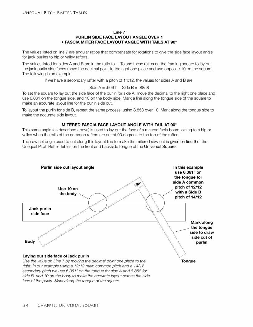
�� Chappell Universal Square
Line 7PURLIN SIDE FACE LAYOUT ANGLE OVER 1
• FASCIA MITER FACE LAYOUT ANGLE WITH TAILS AT 90°
The values listed on line 7 are angular ratios that compensate for rotations to give the side face layout angle for jack purlins to hip or valley rafters.
The values listed for sides A and B are in the ratio to 1. To use these ratios on the framing square to lay out the jack purlin side faces move the decimal point to the right one place and use opposite 10 on the square. The following is an example.
If we have a secondary rafter with a pitch of 14:12, the values for sides A and B are:
Side A = .6061 Side B = .8858To set the square to lay out the side face of the purlin for side A, move the decimal to the right one place and use 6.061 on the tongue side, and 10 on the body side. Mark a line along the tongue side of the square to make an accurate layout line for the purlin side cut.
To layout the purlin for side B, repeat the same process, using 8.858 over 10. Mark along the tongue side to make the accurate side layout.
MITERED FASCIA FACE LAYOUT ANGLE WITH TAIL AT 90°This same angle (as described above) is used to lay out the face of a mitered facia board joining to a hip or valley when the tails of the common rafters are cut at 90 degrees to the top of the rafter.
The saw set angle used to cut along this layout line to make the mitered saw cut is given on line 9 of the Unequal Pitch Rafter Tables on the front and backside tongue of the Universal Square.
CHAPPELL
UNEQUAL PITCHED
12/12 M
AIN P
ITCH A
1
1
2
3
4
5
6
7
8
9
10
11
12
13
14
15
16
17
18
19
20
21
22
EQ
UAL P
ITC
HED
RAFTER
TAB
LE
2
3
4
5
6
7
8
9
10
11
12
13
14
15
16
17
1
2
3
4
5
6
7
8
9
10
11
12
13
14
15
1
2
3
4
5
6
7
8
9
10
11
12
13
14
15
16
17
18
19
20
21
22
23
Body
Tongue
Mark along the tongue
side to draw side cut of
purlin
In this example use 6.061” on the tongue for
side A common pitch of 12/12 with a Side B pitch of 14/12
Use 10 on the body
Jack purlin side face
Laying out side face of jack purlinUse the value on Line 7 by moving the decimal point one place to the right. In our example using a 12/12 main common pitch and a 14/12 secondary pitch we use 6.061” on the tongue for side A and 8.858 for side B, and 10 on the body to make the accurate layout across the side face of the purlin. Mark along the tongue of the square.
Purlin side cut layout angle
Unequal Pitch Rafter Tables
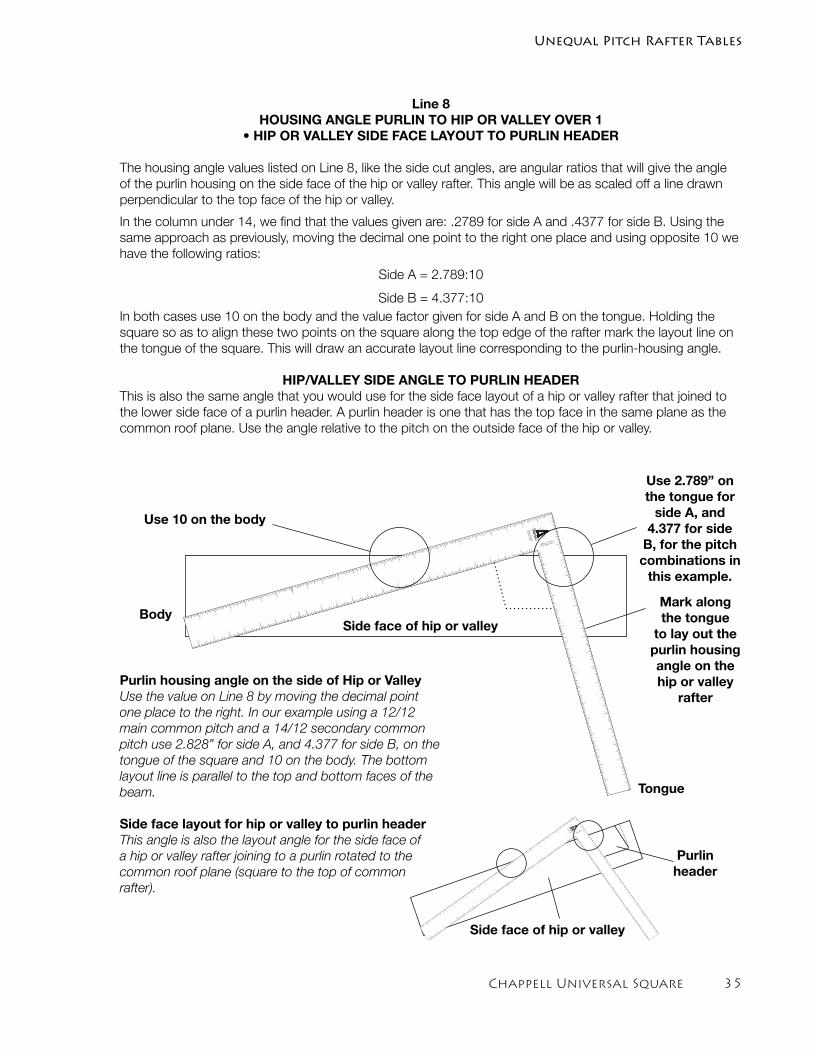
Chappell Universal Square ��
Line 8HOUSING ANGLE PURLIN TO HIP OR VALLEY OVER 1
• HIP OR VALLEY SIDE FACE LAYOUT TO PURLIN HEADER
The housing angle values listed on Line 8, like the side cut angles, are angular ratios that will give the angle of the purlin housing on the side face of the hip or valley rafter. This angle will be as scaled off a line drawn perpendicular to the top face of the hip or valley.
In the column under 14, we find that the values given are: .2789 for side A and .4377 for side B. Using the same approach as previously, moving the decimal one point to the right one place and using opposite 10 we have the following ratios:
Side A = 2.789:10
Side B = 4.377:10In both cases use 10 on the body and the value factor given for side A and B on the tongue. Holding the square so as to align these two points on the square along the top edge of the rafter mark the layout line on the tongue of the square. This will draw an accurate layout line corresponding to the purlin-housing angle.
HIP/VALLEY SIDE ANGLE TO PURLIN HEADER This is also the same angle that you would use for the side face layout of a hip or valley rafter that joined to the lower side face of a purlin header. A purlin header is one that has the top face in the same plane as the common roof plane. Use the angle relative to the pitch on the outside face of the hip or valley.
Purlin housing angle on the side of Hip or ValleyUse the value on Line 8 by moving the decimal point one place to the right. In our example using a 12/12 main common pitch and a 14/12 secondary common pitch use 2.828” for side A, and 4.377 for side B, on the tongue of the square and 10 on the body. The bottom layout line is parallel to the top and bottom faces of the beam.
Side face layout for hip or valley to purlin headerThis angle is also the layout angle for the side face of a hip or valley rafter joining to a purlin rotated to the common roof plane (square to the top of common rafter).
Tongue
BodyMark along the tongue
to lay out the purlin housing angle on the hip or valley
rafter
Use 2.789” on the tongue for
side A, and 4.377 for side
B, for the pitch combinations in
this example.
Use 10 on the body
CHAPPELL
UNEQUAL PITCHED
12/12 MAIN PITCH A
1
1
2
3
4
5
6
7
8
9
10
11
12
13
14
15
16
17
18
19
20
21
22
EQ
UA
L P
ITC
HE
D
RA
FTE
R T
AB
LE
2
3
4
5
6
7
8
9
10
11
12
13
14
15
16
17
1
2
3
4
5
6
7
8
9
10
11
12
13
14
15
1
2
3
4
5
6
7
8
9
10
11
12
13
14
15
16
17
18
19
20
21
22
23
CHAPPELL
UNEQ
UAL PIT
CHED
12/12 M
AIN P
ITC
H A
1
1
2
3
4
5
6
7
8
9
10
11
12
13
14
15
16
17
18
19
20
21
22
EQ
UAL P
ITC
HED
RAFTER T
ABLE
2
3
4
5
6
7
8
9
10
11
12
13
14
15
16
17
1
2
3
4
5
6
7
8
9
10
11
12
13
14
15
1
2
3
4
5
6
7
8
9
10
11
12
13
14
15
16
17
18
19
20
21
22
23
Purlin header
Side face of hip or valley
Side face of hip or valley
Unequal Pitch Rafter Tables
�� Chappell Universal Square
Line 9FASCIA MITER SAW SET ANGLE FOR RAFTER TAILS CUT AT 90°
FASCIA MITER SAW CUT ANGLE TAILS AT 90 DEGREESThe values given on line 9 of the Unequal Pitched Rafter Table are the mitered fascia saw cut angles. These are the angles used to cut the miter angle on fascias along the fascia face layout line as described on line 7 of the Unequal Pitch Table in this section. The values are given as the degree of the cut directly relative to each of the two roof pitches A and B. These angles hold true for all combinations of unequal pitch roof systems as specified in the table when the common rafter tails are cut at 90 degrees to the top face of the rafters (perpendicular to the roof plane).
As an example, if we were to use a common pitch of 9/12 for the Main Pitch A and a 6/12 roof pitch for Secondary Pitch B, we find on the bottom line in the column under 6 on the backside tongue the two values for Pitch A and Pitch B.
The value for Pitch A is 41.731°. This is the degree of the fascia miter saw cut angle relative to pitch A.
The second value under the column for Pitch B is 29.745°. This is the degree of the fascia miter saw cut angle relative to pitch B.
The first step is to lay out the fascia face as described using the values found on line 7 of this section. Once the face layout is complete, simply set your saw to the appropriate angle given on line 9 (relative to pitch A or B as required) and saw along the layout line. The result will be a perfect mitered cut.
Bisecting the Miter CutAs described above, the two joining fascias will be cut at two different angles. This will result in a variance in the length of the angle cut on each fascia, and may require a back cut on one of the fascias to flush them up at the bottom. When the variance in roof pitches is minor, this is the normal approach. However, if the variance in roof pitches is great you may wish to bisect the miter cut so as to arrive at the same miter saw cut angle, and hence, the same length for each of the angle cuts. This is easily accomplished using the values given in the Unequal Pitch Roof Tables as described below.
It is quite simple really. Just add the two values for the degree of the two angles given for Pitch A and Pitch B together and divide them by two. This will give you the bisected miter saw cut angle. As an example, let’s say we had a roof system with a 12/12 Main Pitch A, and an 6/12 Secondary Pitch B. The values on line 9 under columns A and B, under the number 6 on the inch scale, are as follows:
Pitch A = 39.232° Pitch B = 23.578°
The equation to find the bisected angle is as follows: A + B ÷ 2 = Bisected miter angle
39.232 + 23.578 = 62.81 ÷ 2 = 31.405
The bisected miter cut for this example would be 31.405°.
Plumb Cut Rafter Tails When the rafter tails are cut plumb, the miter angle for fascias is equal to the bisected footprint angles. In this case, the fascia face layout is marked at 90°, or square to the fascia board.
Unequal Pitch Rafter Tables
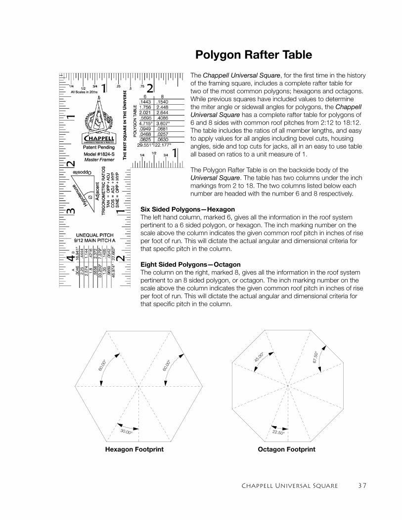
Chappell Universal Square ��
Polygon Rafter Table
The Chappell Universal Square, for the first time in the history of the framing square, includes a complete rafter table for two of the most common polygons; hexagons and octagons. While previous squares have included values to determine the miter angle or sidewall angles for polygons, the Chappell Universal Square has a complete rafter table for polygons of 6 and 8 sides with common roof pitches from 2:12 to 18:12. The table includes the ratios of all member lengths, and easy to apply values for all angles including bevel cuts, housing angles, side and top cuts for jacks, all in an easy to use table all based on ratios to a unit measure of 1.
The Polygon Rafter Table is on the backside body of the Universal Square. The table has two columns under the inch markings from 2 to 18. The two columns listed below each number are headed with the number 6 and 8 respectively.
Six Sided Polygons—HexagonThe left hand column, marked 6, gives all the information in the roof system pertinent to a 6 sided polygon, or hexagon. The inch marking number on the scale above the column indicates the given common roof pitch in inches of rise per foot of run. This will dictate the actual angular and dimensional criteria for that specific pitch in the column.
Eight Sided Polygons—OctagonThe column on the right, marked 8, gives all the information in the roof system pertinent to an 8 sided polygon, or octagon. The inch marking number on the scale above the column indicates the given common roof pitch in inches of rise per foot of run. This will dictate the actual angular and dimensional criteria for that specific pitch in the column.
Hexagon Footprint Octagon Footprint
60.00° 4
5.00°
30.00°22.50°
67.50°
60.00°
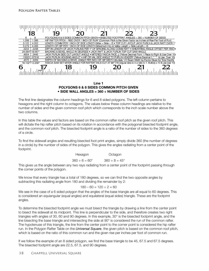
�� Chappell Universal Square
Line 1POLYGONS 6 & 8 SIDES COMMON PITCH GIVEN
• SIDE WALL ANGLES = 360 ÷ NUMBER OF SIDES
The first line designates the column headings for 6 and 8 sided polygons. The left column pertains to hexagons and the right column to octagons. The values below these column headings are relative to the number of sides and the given common roof pitch which corresponds to the inch scale number above the two columns.
In this table the values and factors are based on the common rafter roof pitch as the given roof pitch. This will dictate the hip rafter pitch based on its rotation in accordance with the polygonal bisected footprint angle, and the common roof pitch. The bisected footprint angle is a ratio of the number of sides to the 360 degrees of a circle.
To find the sidewall angles and resulting bisected foot print angles, simply divide 360 (the number of degrees in a circle) by the number of sides of the polygon. This gives the angles radiating from a center point of the footprint.
Hexagon Octagon
360 ÷ 6 = 60° 360 ÷ 8 = 45°This gives us the angle between any two rays radiating from a center point of the footprint passing through the corner points of the polygon.
We know that every triangle has a total of 180 degrees, so we can find the two opposite angles by subtracting this radiating angle from 180 and dividing the remainder by 2:
180 – 60 = 120 ÷ 2 = 60We see in the case of a 6 sided polygon that the angles of the base triangle are all equal to 60 degrees. This is considered an equiangular (equal angles) and equilateral (equal sides) triangle. These are the footprint angles.
To determine the bisected footprint angle we must bisect the triangle by drawing a line from the center point to bisect the sidewall at its midpoint. This line is perpendicular to the side, and therefore creates two right triangles with angles of 30, 60 and 90 degrees. In this example, 30° is the bisected footprint angle, and the line bisecting the base triangle and intersecting the side at 90° is considered the run of the common rafter. The hypotenuse of this triangle, the line from the center point to the corner point is considered the hip rafter run. In the Polygon Rafter Table on the Universal Square, the given pitch is based on the common roof pitch, which is based on the ratio of this common run and the given rise per inches per foot of common run.
If we follow the example of an 8 sided polygon, we find the base triangle to be 45, 67.5 and 67.5 degrees. The bisected footprint angle are 22.5, 67.5, and 90 degrees.
Polygon Rafter Tables
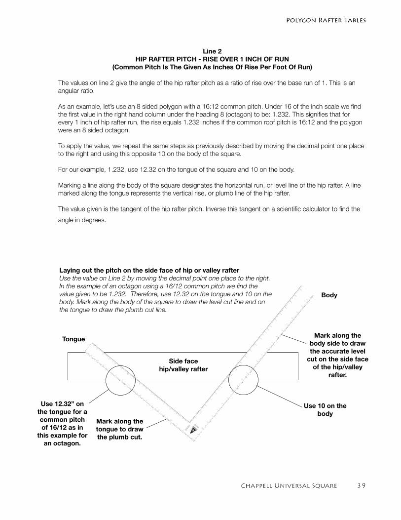
Chappell Universal Square ��
Polygon Rafter Tables
Line 2HIP RAFTER PITCH - RISE OVER 1 INCH OF RUN
(Common Pitch Is The Given As Inches Of Rise Per Foot Of Run)
The values on line 2 give the angle of the hip rafter pitch as a ratio of rise over the base run of 1. This is an angular ratio.
As an example, let’s use an 8 sided polygon with a 16:12 common pitch. Under 16 of the inch scale we find the first value in the right hand column under the heading 8 (octagon) to be: 1.232. This signifies that for every 1 inch of hip rafter run, the rise equals 1.232 inches if the common roof pitch is 16:12 and the polygon were an 8 sided octagon.
To apply the value, we repeat the same steps as previously described by moving the decimal point one place to the right and using this opposite 10 on the body of the square.
For our example, 1.232, use 12.32 on the tongue of the square and 10 on the body.
Marking a line along the body of the square designates the horizontal run, or level line of the hip rafter. A line marked along the tongue represents the vertical rise, or plumb line of the hip rafter.
The value given is the tangent of the hip rafter pitch. Inverse this tangent on a scientific calculator to find the
angle in degrees.
CHAPPELL
UNEQUAL P
ITCHED
12/1
2 M
AIN
PIT
CH A
1
1
2
3
4
5
6
7
8
9
10
11
12
13
14
15
16
17
18
19
20
21
22
EQUAL
PIT
CHED
RAFT
ER T
ABLE
2
3
4
5
6
7
8
9
10
11
12
13
14
15
16
17
1
2
3
4
5
6
7
8
9
10
11
12
13
14
15
1
2
3
4
5
6
7
8
9
10
11
12
13
14
15
16
17
18
19
20
21
22
23
Body
Tongue Mark along the body side to draw the accurate level
cut on the side face of the hip/valley
rafter.
Laying out the pitch on the side face of hip or valley rafterUse the value on Line 2 by moving the decimal point one place to the right. In the example of an octagon using a 16/12 common pitch we find the value given to be 1.232. Therefore, use 12.32 on the tongue and 10 on the body. Mark along the body of the square to draw the level cut line and on the tongue to draw the plumb cut line.
Use 12.32” on the tongue for a common pitch of 16/12 as in
this example for an octagon.
Use 10 on the body
Side face hip/valley rafter
Mark along the tongue to draw the plumb cut.
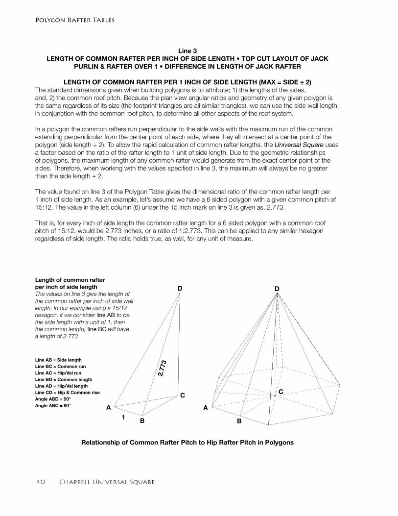
�0 Chappell Universal Square
Line 3 LENGTH OF COMMON RAFTER PER INCH OF SIDE LENGTH • TOP CUT LAYOUT OF JACK
PURLIN & RAFTER OVER 1 • DIFFERENCE IN LENGTH OF JACK RAFTER
LENGTH OF COMMON RAFTER PER 1 INCH OF SIDE LENGTH (MAX = SIDE ÷ 2)The standard dimensions given when building polygons is to attribute; 1) the lengths of the sides,and, 2) the common roof pitch. Because the plan view angular ratios and geometry of any given polygon is the same regardless of its size (the footprint triangles are all similar triangles), we can use the side wall length, in conjunction with the common roof pitch, to determine all other aspects of the roof system.
In a polygon the common rafters run perpendicular to the side walls with the maximum run of the common extending perpendicular from the center point of each side, where they all intersect at a center point of the polygon (side length ÷ 2). To allow the rapid calculation of common rafter lengths, the Universal Square uses a factor based on the ratio of the rafter length to 1 unit of side length. Due to the geometric relationships of polygons, the maximum length of any common rafter would generate from the exact center point of the sides. Therefore, when working with the values specified in line 3, the maximum will always be no greater than the side length ÷ 2.
The value found on line 3 of the Polygon Table gives the dimensional ratio of the common rafter length per 1 inch of side length. As an example, let’s assume we have a 6 sided polygon with a given common pitch of 15:12. The value in the left column (6) under the 15 inch mark on line 3 is given as, 2.773.
That is, for every inch of side length the common rafter length for a 6 sided polygon with a common roof pitch of 15:12, would be 2.773 inches, or a ratio of 1:2.773. This can be applied to any similar hexagon regardless of side length. The ratio holds true, as well, for any unit of measure.
Line AB = Side lengthLine BC = Common runLine AC = Hip/Val runLine BD = Common lengthLine AD = Hip/Val length Line CD = Hip & Common riseAngle ABD = 90°Angle ABC = 90° A
B
C
D
A
B
C
D
1
2.77
3
Length of common rafter per inch of side lengthThe values on line 3 give the length of the common rafter per inch of side wall length. In our example using a 15/12 hexagon, if we consider line AB to be the side length with a unit of 1, then the common length, line BC will have a length of 2.773
Polygon Rafter Tables
Relationship of Common Rafter Pitch to Hip Rafter Pitch in Polygons
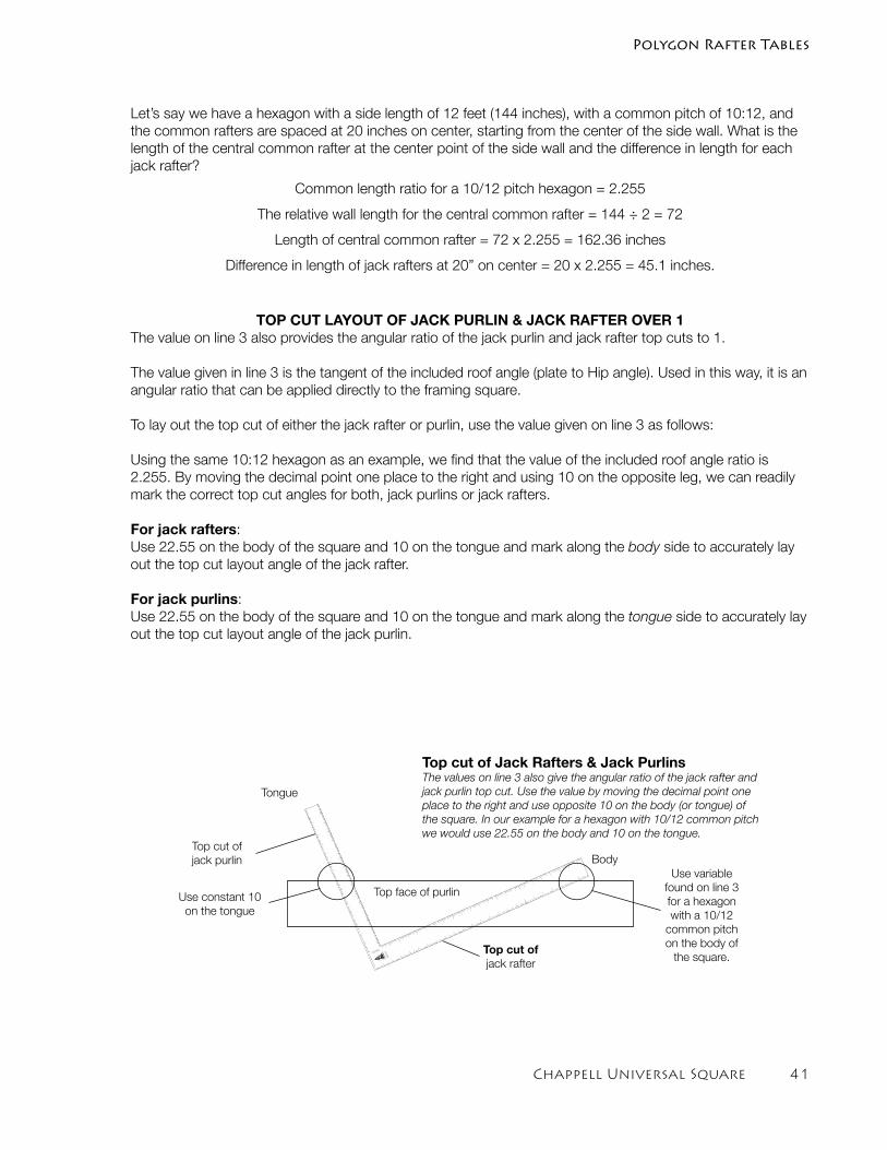
Chappell Universal Square �1
Polygon Rafter Tables
Let’s say we have a hexagon with a side length of 12 feet (144 inches), with a common pitch of 10:12, and the common rafters are spaced at 20 inches on center, starting from the center of the side wall. What is the length of the central common rafter at the center point of the side wall and the difference in length for each jack rafter?
Common length ratio for a 10/12 pitch hexagon = 2.255
The relative wall length for the central common rafter = 144 ÷ 2 = 72
Length of central common rafter = 72 x 2.255 = 162.36 inches
Difference in length of jack rafters at 20” on center = 20 x 2.255 = 45.1 inches.
TOP CUT LAYOUT OF JACK PURLIN & JACK RAFTER OVER 1 The value on line 3 also provides the angular ratio of the jack purlin and jack rafter top cuts to 1.
The value given in line 3 is the tangent of the included roof angle (plate to Hip angle). Used in this way, it is an angular ratio that can be applied directly to the framing square.
To lay out the top cut of either the jack rafter or purlin, use the value given on line 3 as follows:
Using the same 10:12 hexagon as an example, we find that the value of the included roof angle ratio is 2.255. By moving the decimal point one place to the right and using 10 on the opposite leg, we can readily mark the correct top cut angles for both, jack purlins or jack rafters.
For jack rafters:Use 22.55 on the body of the square and 10 on the tongue and mark along the body side to accurately lay out the top cut layout angle of the jack rafter.
For jack purlins:Use 22.55 on the body of the square and 10 on the tongue and mark along the tongue side to accurately lay out the top cut layout angle of the jack purlin.
Body
Top cut of jack rafter
Top cut of jack purlin
Use constant 10 on the tongue
Use variable found on line 3 for a hexagon with a 10/12
common pitchon the body of
the square.CHAPPELL
UNEQUAL PITCHED
12/12 MAIN PITCH A
1
1
2
3
4
5
6
7
8
9
10
11
12
13
14
15
16
17
18
19
20
21
22
EQ
UAL P
ITC
HED
RA
FTER
TA
BLE2
3
4
5
6
7
8
9
10
11
12
13
14
15
16
17
1
2
3
4
5
6
7
8
9
10
11
12
13
14
15
1
2
3
4
5
6
7
8
9
10
11
12
13
14
15
16
17
18
19
20
21
22
23
Tongue
Top face of purlin
Top cut of Jack Rafters & Jack PurlinsThe values on line 3 also give the angular ratio of the jack rafter and jack purlin top cut. Use the value by moving the decimal point one place to the right and use opposite 10 on the body (or tongue) of the square. In our example for a hexagon with 10/12 common pitch we would use 22.55 on the body and 10 on the tongue.
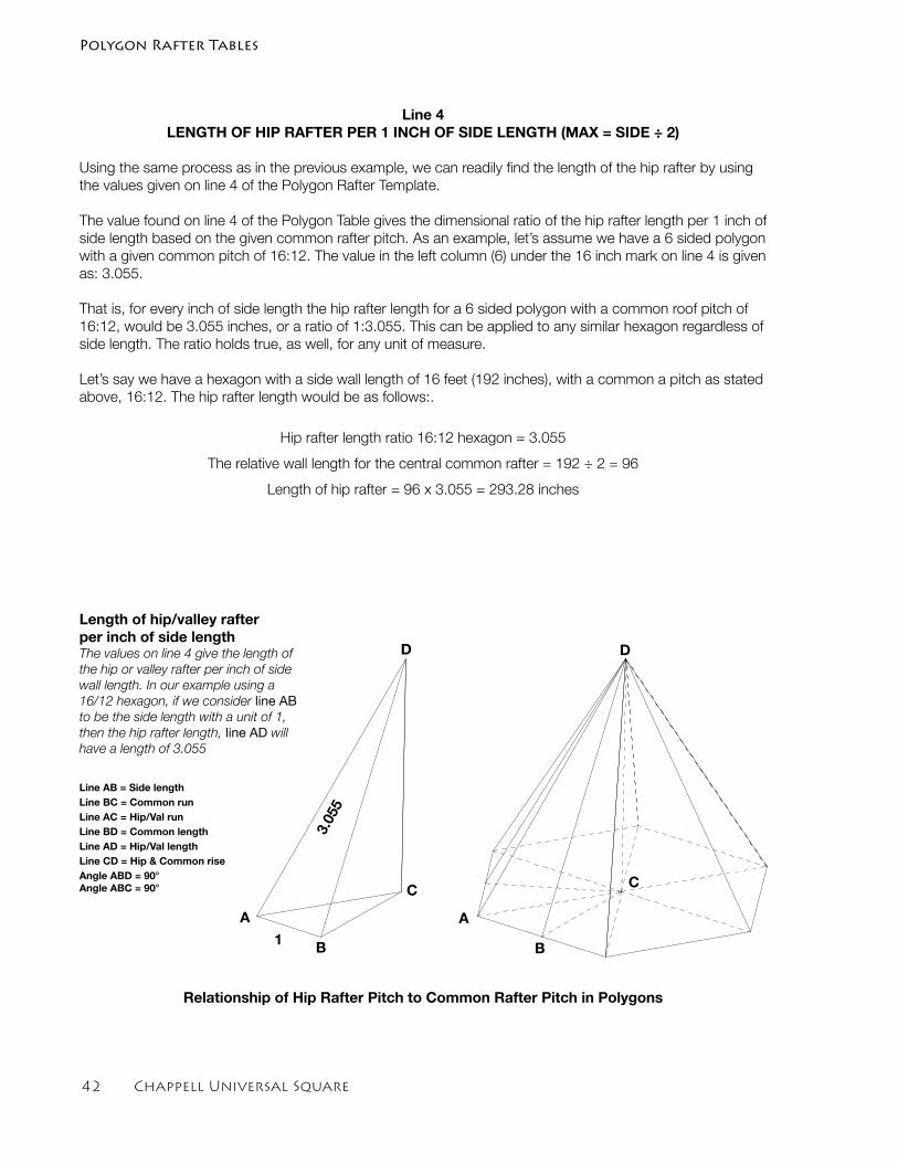
�2 Chappell Universal Square
Line 4 LENGTH OF HIP RAFTER PER 1 INCH OF SIDE LENGTH (MAX = SIDE ÷ 2)
Using the same process as in the previous example, we can readily find the length of the hip rafter by using the values given on line 4 of the Polygon Rafter Template.
The value found on line 4 of the Polygon Table gives the dimensional ratio of the hip rafter length per 1 inch of side length based on the given common rafter pitch. As an example, let’s assume we have a 6 sided polygon with a given common pitch of 16:12. The value in the left column (6) under the 16 inch mark on line 4 is given as: 3.055.
That is, for every inch of side length the hip rafter length for a 6 sided polygon with a common roof pitch of 16:12, would be 3.055 inches, or a ratio of 1:3.055. This can be applied to any similar hexagon regardless of side length. The ratio holds true, as well, for any unit of measure.
Let’s say we have a hexagon with a side wall length of 16 feet (192 inches), with a common a pitch as stated above, 16:12. The hip rafter length would be as follows:.
Hip rafter length ratio 16:12 hexagon = 3.055
The relative wall length for the central common rafter = 192 ÷ 2 = 96
Length of hip rafter = 96 x 3.055 = 293.28 inches
Line AB = Side lengthLine BC = Common runLine AC = Hip/Val runLine BD = Common lengthLine AD = Hip/Val lengthLine CD = Hip & Common riseAngle ABD = 90°Angle ABC = 90°
A
B
C
D
A
B
C
D
1
3.05
5
Length of hip/valley rafter per inch of side lengthThe values on line 4 give the length of the hip or valley rafter per inch of side wall length. In our example using a 16/12 hexagon, if we consider line AB to be the side length with a unit of 1, then the hip rafter length, line AD will have a length of 3.055
Polygon Rafter Tables
Relationship of Hip Rafter Pitch to Common Rafter Pitch in Polygons
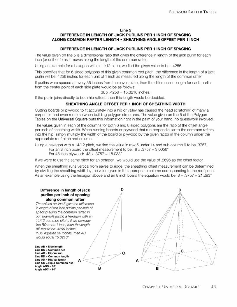
Chappell Universal Square ��
Polygon Rafter Tables
Line 5 DIFFERENCE IN LENGTH OF JACK PURLINS PER 1 INCH OF SPACING
ALONG COMMON RAFTER LENGTH • SHEATHING ANGLE OFFSET PER 1 INCH
DIFFERENCE IN LENGTH OF JACK PURLINS PER 1 INCH OF SPACING
The value given on line 5 is a dimensional ratio that gives the difference in length of the jack purlin for each inch (or unit of 1) as it moves along the length of the common rafter.
Using an example for a hexagon with a 11:12 pitch, we find the given value to be: .4256.
This specifies that for 6 sided polygons of this given common roof pitch, the difference in the length of a jack purlin will be .4256 inches for each unit of 1 inch as measured along the length of the common rafter.
If purlins were spaced at every 36 inches from the eaves plate, then the difference in length for each purlin from the center point of each side plate would be as follows:
36 x .4256 = 15.3216 inches.If the purlin joins directly to both hip rafters, then this length would be doubled.
SHEATHING ANGLE OFFSET PER 1 INCH OF SHEATHING WIDTH
Cutting boards or plywood to fit accurately into a hip or valley has caused the head scratching of many a carpenter, and even more so when building polygon structures. The value given on line 5 of the Polygon Tables on the Universal Square puts this information right in the palm of your hand, no guesswork involved.
The values given in each of the columns for both 6 and 8 sided polygons are the ratio of the offset angle per inch of sheathing width. When running boards or plywood that run perpendicular to the common rafters into the hip, simply multiply the width of the board or plywood by the given factor in the column under the appropriate roof pitch and column.
Using a hexagon with a 14/12 pitch, we find the value in row 5 under 14 and sub column 6 to be .3757. For an 8 inch board the offset measurement to be: 8 x .3757 = 3.0056” For 48 inch plywood: 48 x .3757 = 18.033”
If we were to use the same pitch for an octagon, we would use the value of .2696 as the offset factor.
When the sheathing runs vertical from eaves to ridge, the sheathing offset measurement can be determined by dividing the sheathing width by the value given in the appropriate column corresponding to the roof pitch. As an example using the hexagon above and an 8 inch board the equation would be: 8 ÷ .3757 = 21.293”
Line AB = Side lengthLine BC = Common runLine AC = Hip/Val runLine BD = Common lengthLine AD = Hip/Val length Line CD = Hip & Common riseAngle ABD = 90°Angle ABC = 90°
A
B
C
D
A
B
C
DDifference in length of jack purlins per inch of spacing
along common rafterThe values on line 5 give the difference in length of the jack purlins per inch of spacing along the common rafter. In our example (using a hexagon with an 11/12 common pitch), if we consider line BD to be 1 inch, then the length AB would be .4256 inches. If BD equaled 36 inches, then AB would equal 15.3216”
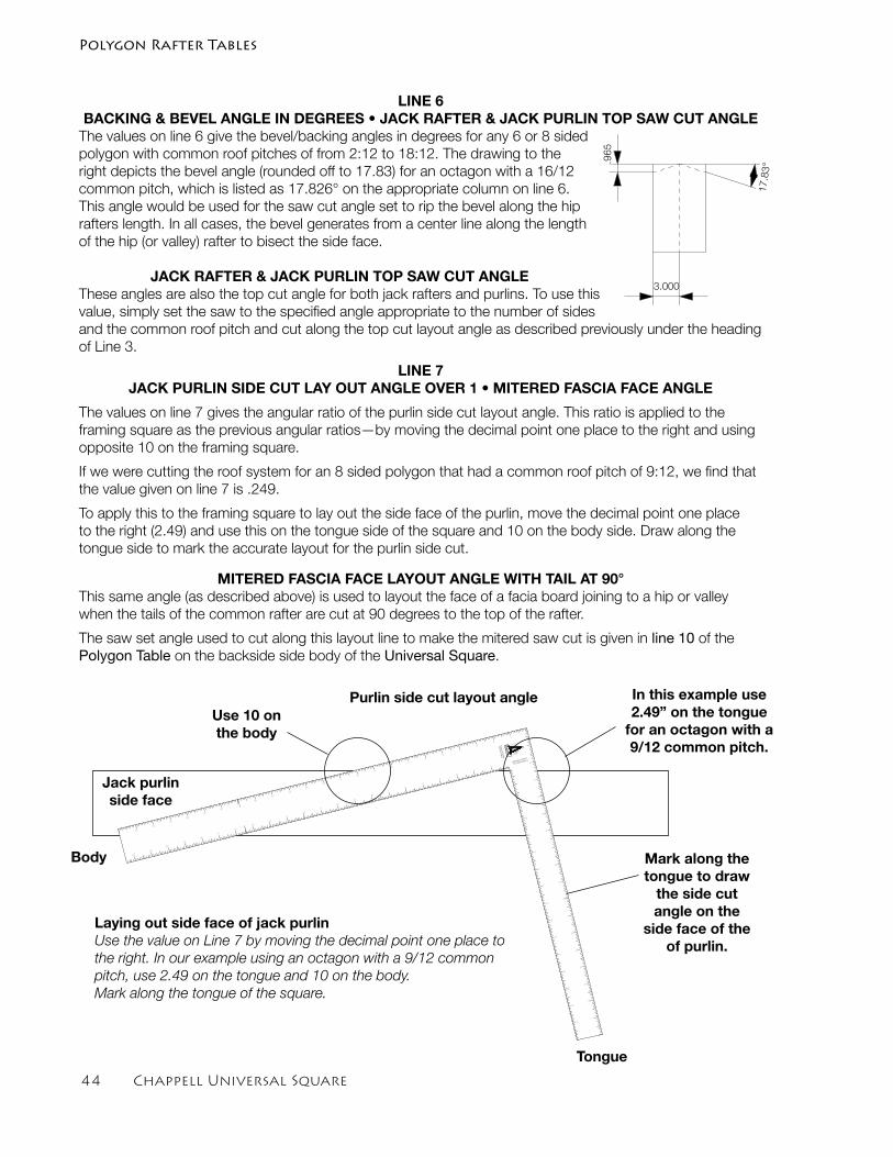
�� Chappell Universal Square
LINE 6BACKING & BEVEL ANGLE IN DEGREES • JACK RAFTER & JACK PURLIN TOP SAW CUT ANGLE
The values on line 6 give the bevel/backing angles in degrees for any 6 or 8 sided polygon with common roof pitches of from 2:12 to 18:12. The drawing to the right depicts the bevel angle (rounded off to 17.83) for an octagon with a 16/12 common pitch, which is listed as 17.826° on the appropriate column on line 6. This angle would be used for the saw cut angle set to rip the bevel along the hip rafters length. In all cases, the bevel generates from a center line along the length of the hip (or valley) rafter to bisect the side face.
JACK RAFTER & JACK PURLIN TOP SAW CUT ANGLEThese angles are also the top cut angle for both jack rafters and purlins. To use this value, simply set the saw to the specified angle appropriate to the number of sides and the common roof pitch and cut along the top cut layout angle as described previously under the heading of Line 3.
LINE 7 JACK PURLIN SIDE CUT LAY OUT ANGLE OVER 1 • MITERED FASCIA FACE ANGLE
The values on line 7 gives the angular ratio of the purlin side cut layout angle. This ratio is applied to the framing square as the previous angular ratios—by moving the decimal point one place to the right and using opposite 10 on the framing square.
If we were cutting the roof system for an 8 sided polygon that had a common roof pitch of 9:12, we find that the value given on line 7 is .249.
To apply this to the framing square to lay out the side face of the purlin, move the decimal point one place to the right (2.49) and use this on the tongue side of the square and 10 on the body side. Draw along the tongue side to mark the accurate layout for the purlin side cut.
MITERED FASCIA FACE LAYOUT ANGLE WITH TAIL AT 90°This same angle (as described above) is used to layout the face of a facia board joining to a hip or valley when the tails of the common rafter are cut at 90 degrees to the top of the rafter.
The saw set angle used to cut along this layout line to make the mitered saw cut is given in line 10 of the Polygon Table on the backside side body of the Universal Square.
3.000
.965
17.83°
CHAPPELL
UNEQUAL PITCHED
12/12 MAIN PITCH A
1
1
2
3
4
5
6
7
8
9
10
11
12
13
14
15
16
17
18
19
20
21
22
EQ
UA
L P
ITC
HE
D
RA
FTE
R T
AB
LE
2
3
4
5
6
7
8
9
10
11
12
13
14
15
16
17
1
2
3
4
5
6
7
8
9
10
11
12
13
14
15
1
2
3
4
5
6
7
8
9
10
11
12
13
14
15
16
17
18
19
20
21
22
23
Body
Tongue
Mark along the tongue to draw
the side cut angle on the
side face of the of purlin.
In this example use 2.49” on the tongue
for an octagon with a 9/12 common pitch.
Use 10 on the body
Jack purlin side face
Laying out side face of jack purlinUse the value on Line 7 by moving the decimal point one place to the right. In our example using an octagon with a 9/12 common pitch, use 2.49 on the tongue and 10 on the body. Mark along the tongue of the square.
Purlin side cut layout angle
Polygon Rafter Tables
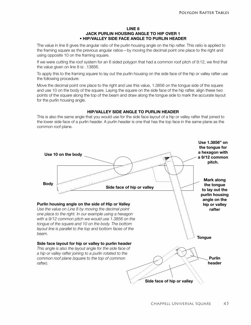
Chappell Universal Square ��
Polygon Rafter Tables
LINE 8 JACK PURLIN HOUSING ANGLE TO HIP OVER 1
• HIP/VALLEY SIDE FACE ANGLE TO PURLIN HEADER
The value in line 8 gives the angular ratio of the purlin housing angle on the hip rafter. This ratio is applied to the framing square as the previous angular ratios—by moving the decimal point one place to the right and using opposite 10 on the framing square.
If we were cutting the roof system for an 6 sided polygon that had a common roof pitch of 9:12, we find that the value given on line 8 is: .13856.
To apply this to the framing square to lay out the purlin housing on the side face of the hip or valley rafter use the following procedure:
Move the decimal point one place to the right and use this value, 1.3856 on the tongue side of the square and use 10 on the body of the square. Laying the square on the side face of the hip rafter, align these two points of the square along the top of the beam and draw along the tongue side to mark the accurate layout for the purlin housing angle.
HIP/VALLEY SIDE ANGLE TO PURLIN HEADER This is also the same angle that you would use for the side face layout of a hip or valley rafter that joined to the lower side face of a purlin header. A purlin header is one that has the top face in the same plane as the common roof plane.
Tongue
BodyMark along the tongue
to lay out the purlin housing angle on the hip or valley
rafter
Use 1.3856” on the tongue for a hexagon with a 9/12 common
pitch.
Use 10 on the body
CHAPPELL
UNEQUAL PITCHED
12/12 MAIN PITCH A
1
1
2
3
4
5
6
7
8
9
10
11
12
13
14
15
16
17
18
19
20
21
22
EQ
UA
L P
ITC
HE
D
RA
FTE
R T
AB
LE
2
3
4
5
6
7
8
9
10
11
12
13
14
15
16
17
1
2
3
4
5
6
7
8
9
10
11
12
13
14
15
1
2
3
4
5
6
7
8
9
10
11
12
13
14
15
16
17
18
19
20
21
22
23
CHAPPELL
UNEQ
UAL PIT
CHED
12/12 M
AIN P
ITC
H A
1
1
2
3
4
5
6
7
8
9
10
11
12
13
14
15
16
17
18
19
20
21
22
EQ
UAL P
ITC
HED
RAFTER T
ABLE
2
3
4
5
6
7
8
9
10
11
12
13
14
15
16
17
1
2
3
4
5
6
7
8
9
10
11
12
13
14
15
1
2
3
4
5
6
7
8
9
10
11
12
13
14
15
16
17
18
19
20
21
22
23
Purlin header
Side face of hip or valley
Side face of hip or valley
Purlin housing angle on the side of Hip or ValleyUse the value on Line 8 by moving the decimal point one place to the right. In our example using a hexagon with a 9/12 common pitch we would use 1.3856 on the tongue of the square and 10 on the body. The bottom layout line is parallel to the top and bottom faces of the beam.
Side face layout for hip or valley to purlin headerThis angle is also the layout angle for the side face of a hip or valley rafter joining to a purlin rotated to the common roof plane (square to the top of common rafter).
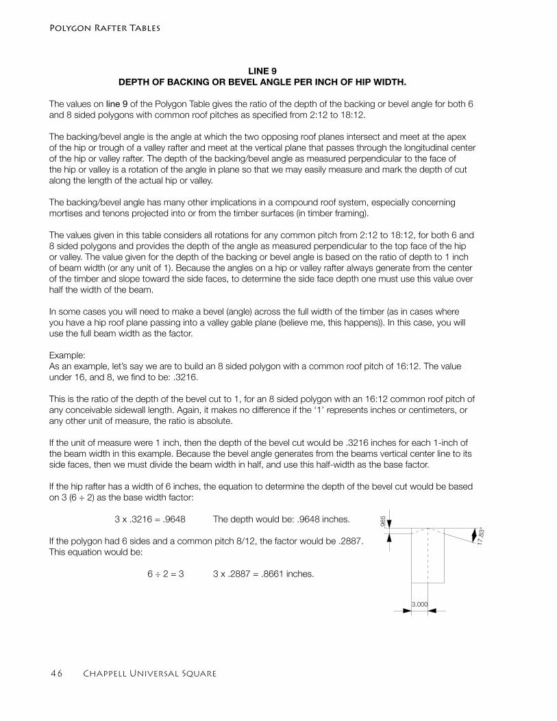
�� Chappell Universal Square
LINE 9DEPTH OF BACKING OR BEVEL ANGLE PER INCH OF HIP WIDTH.
The values on line 9 of the Polygon Table gives the ratio of the depth of the backing or bevel angle for both 6 and 8 sided polygons with common roof pitches as specified from 2:12 to 18:12.
The backing/bevel angle is the angle at which the two opposing roof planes intersect and meet at the apex of the hip or trough of a valley rafter and meet at the vertical plane that passes through the longitudinal center of the hip or valley rafter. The depth of the backing/bevel angle as measured perpendicular to the face of the hip or valley is a rotation of the angle in plane so that we may easily measure and mark the depth of cut along the length of the actual hip or valley.
The backing/bevel angle has many other implications in a compound roof system, especially concerning mortises and tenons projected into or from the timber surfaces (in timber framing).
The values given in this table considers all rotations for any common pitch from 2:12 to 18:12, for both 6 and 8 sided polygons and provides the depth of the angle as measured perpendicular to the top face of the hip or valley. The value given for the depth of the backing or bevel angle is based on the ratio of depth to 1 inch of beam width (or any unit of 1). Because the angles on a hip or valley rafter always generate from the center of the timber and slope toward the side faces, to determine the side face depth one must use this value over half the width of the beam.
In some cases you will need to make a bevel (angle) across the full width of the timber (as in cases where you have a hip roof plane passing into a valley gable plane (believe me, this happens)). In this case, you will use the full beam width as the factor.
Example:As an example, let’s say we are to build an 8 sided polygon with a common roof pitch of 16:12. The value under 16, and 8, we find to be: .3216.
This is the ratio of the depth of the bevel cut to 1, for an 8 sided polygon with an 16:12 common roof pitch of any conceivable sidewall length. Again, it makes no difference if the ‘1’ represents inches or centimeters, or any other unit of measure, the ratio is absolute.
If the unit of measure were 1 inch, then the depth of the bevel cut would be .3216 inches for each 1-inch of the beam width in this example. Because the bevel angle generates from the beams vertical center line to its side faces, then we must divide the beam width in half, and use this half-width as the base factor.
If the hip rafter has a width of 6 inches, the equation to determine the depth of the bevel cut would be based on 3 (6 ÷ 2) as the base width factor:
3 x .3216 = .9648 The depth would be: .9648 inches.
If the polygon had 6 sides and a common pitch 8/12, the factor would be .2887. This equation would be:
6 ÷ 2 = 3 3 x .2887 = .8661 inches.
3.000
.965
17.83°
Polygon Rafter Tables
Chappell Universal Square ��
Polygon Rafter Tables
Line 10FASCIA SAW SET MITER ANGLE FOR RAFTER TAILS CUT AT 90°
The values on line 10 of the Polygon Rafter Table give the mitered fascia saw cut angles for both 6 and 8 sided polygon roof systems with common roof pitches ranging from 2/12 to 18/12. These are the angles used to cut the miter angle on fascias along the fascia face layout line as described on line 7 of the Polygon Table in this section. The values are given as the degree of the miter cut directly relative to the number of sides (6 or 8). These angles hold true for all roof systems as specified in the table when the common rafter tails are cut at 90 degrees to the top face of the rafters (perpendicular to the roof plane).
As an example, if we were to build a hexagon with a common roof pitch of 16/12, we find on the bottom line in the column under the number 16 (and further under the sub column 6), the degree of the fascia miter angle directly. In this example the miter angle is 17.458°
If we were building an octagon with the same common roof pitch, the miter angle will be 13.274°.
The first step is to lay out the fascia face angle as described on page 44 for line 7 under the sub-heading for the MITERED FASCIA FACE ANGLE. Once the face layout is complete, simply set your saw to the appropriate angle as given on line 10 (relative to a 6 or 8 sided polygon as your design dictates) and saw along the layout line. The result will be a perfect mitered cut.
Plumb Cut Rafter Tails When the common rafter tails are cut plumb, the miter angle for fascias are equal to the polygon bisected footprint angles divided by two. In this case, the fascia face layout is marked at 90°, or square to the fascia board.
Determining the bisected footprint angle is discussed on the first page of this section. The equation can also be found on the first line of the Polygon Table. The equation for polygons being:
Bisected footprint angle = 360 ÷ Number of sides of polygon
To apply this to the fascia, we have to bisect this angle once more.
For a hexagon we have:
360 ÷ 6 = 60 ÷ 2 = 30. The fascia miter angle is 30°
For a hexagon we have:
360 ÷ 8 = 45 ÷ 2 = 22.5 The fascia miter angle is 22.5°
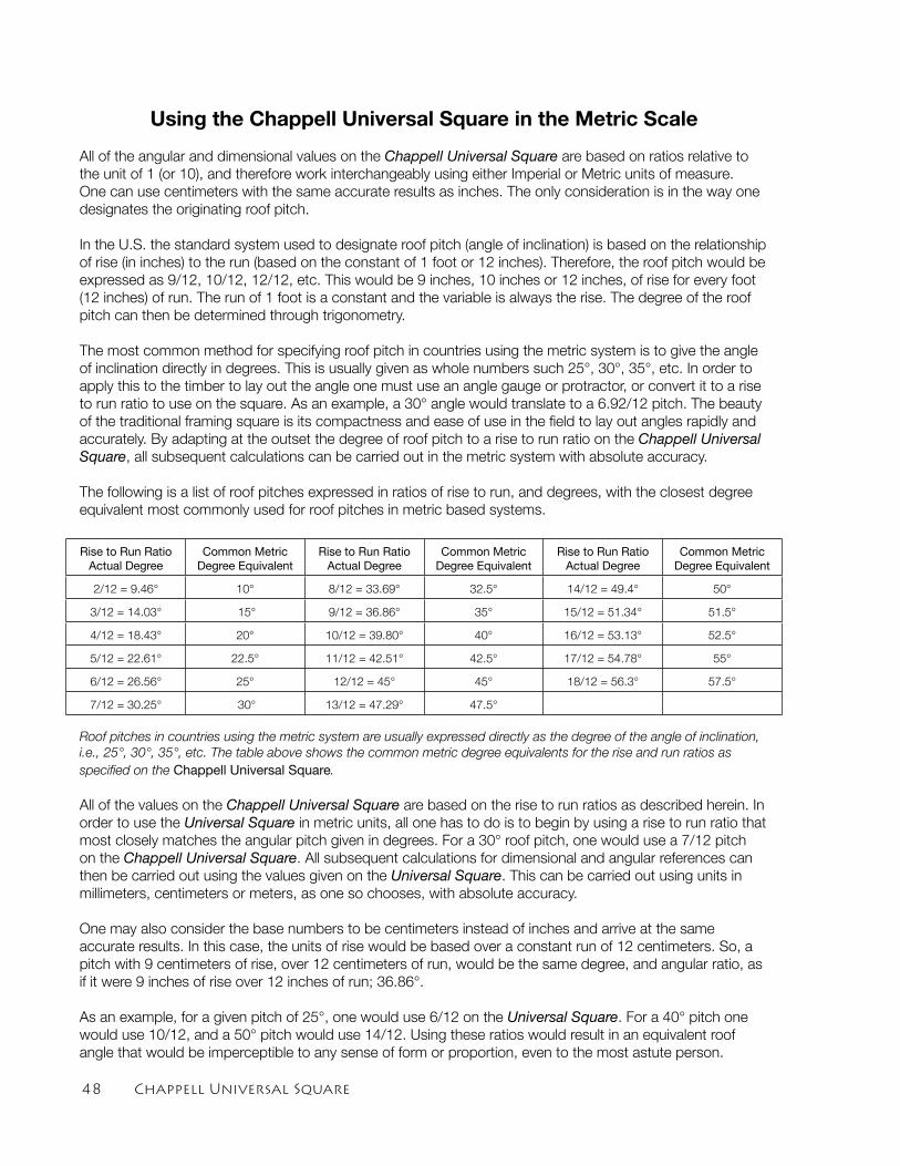
�� Chappell Universal Square
Using the Chappell Universal Square in the Metric Scale
All of the angular and dimensional values on the Chappell Universal Square are based on ratios relative to the unit of 1 (or 10), and therefore work interchangeably using either Imperial or Metric units of measure. One can use centimeters with the same accurate results as inches. The only consideration is in the way one designates the originating roof pitch.
In the U.S. the standard system used to designate roof pitch (angle of inclination) is based on the relationship of rise (in inches) to the run (based on the constant of 1 foot or 12 inches). Therefore, the roof pitch would be expressed as 9/12, 10/12, 12/12, etc. This would be 9 inches, 10 inches or 12 inches, of rise for every foot (12 inches) of run. The run of 1 foot is a constant and the variable is always the rise. The degree of the roof pitch can then be determined through trigonometry.
The most common method for specifying roof pitch in countries using the metric system is to give the angle of inclination directly in degrees. This is usually given as whole numbers such 25°, 30°, 35°, etc. In order to apply this to the timber to lay out the angle one must use an angle gauge or protractor, or convert it to a rise to run ratio to use on the square. As an example, a 30° angle would translate to a 6.92/12 pitch. The beauty of the traditional framing square is its compactness and ease of use in the field to lay out angles rapidly and accurately. By adapting at the outset the degree of roof pitch to a rise to run ratio on the Chappell Universal Square, all subsequent calculations can be carried out in the metric system with absolute accuracy.
The following is a list of roof pitches expressed in ratios of rise to run, and degrees, with the closest degree equivalent most commonly used for roof pitches in metric based systems.
Rise to Run Ratio Actual Degree
Common MetricDegree Equivalent
Rise to Run Ratio Actual Degree
Common MetricDegree Equivalent
Rise to Run Ratio Actual Degree
Common MetricDegree Equivalent
2/12 = 9.46° 10° 8/12 = 33.69° 32.5° 14/12 = 49.4° 50°
3/12 = 14.03° 15° 9/12 = 36.86° 35° 15/12 = 51.34° 51.5°
4/12 = 18.43° 20° 10/12 = 39.80° 40° 16/12 = 53.13° 52.5°
5/12 = 22.61° 22.5° 11/12 = 42.51° 42.5° 17/12 = 54.78° 55°
6/12 = 26.56° 25° 12/12 = 45° 45° 18/12 = 56.3° 57.5°
7/12 = 30.25° 30° 13/12 = 47.29° 47.5°
Roof pitches in countries using the metric system are usually expressed directly as the degree of the angle of inclination, i.e., 25°, 30°, 35°, etc. The table above shows the common metric degree equivalents for the rise and run ratios as specified on the Chappell Universal Square.
All of the values on the Chappell Universal Square are based on the rise to run ratios as described herein. In order to use the Universal Square in metric units, all one has to do is to begin by using a rise to run ratio that most closely matches the angular pitch given in degrees. For a 30° roof pitch, one would use a 7/12 pitch on the Chappell Universal Square. All subsequent calculations for dimensional and angular references can then be carried out using the values given on the Universal Square. This can be carried out using units in millimeters, centimeters or meters, as one so chooses, with absolute accuracy.
One may also consider the base numbers to be centimeters instead of inches and arrive at the same accurate results. In this case, the units of rise would be based over a constant run of 12 centimeters. So, a pitch with 9 centimeters of rise, over 12 centimeters of run, would be the same degree, and angular ratio, as if it were 9 inches of rise over 12 inches of run; 36.86°.
As an example, for a given pitch of 25°, one would use 6/12 on the Universal Square. For a 40° pitch one would use 10/12, and a 50° pitch would use 14/12. Using these ratios would result in an equivalent roof angle that would be imperceptible to any sense of form or proportion, even to the most astute person.
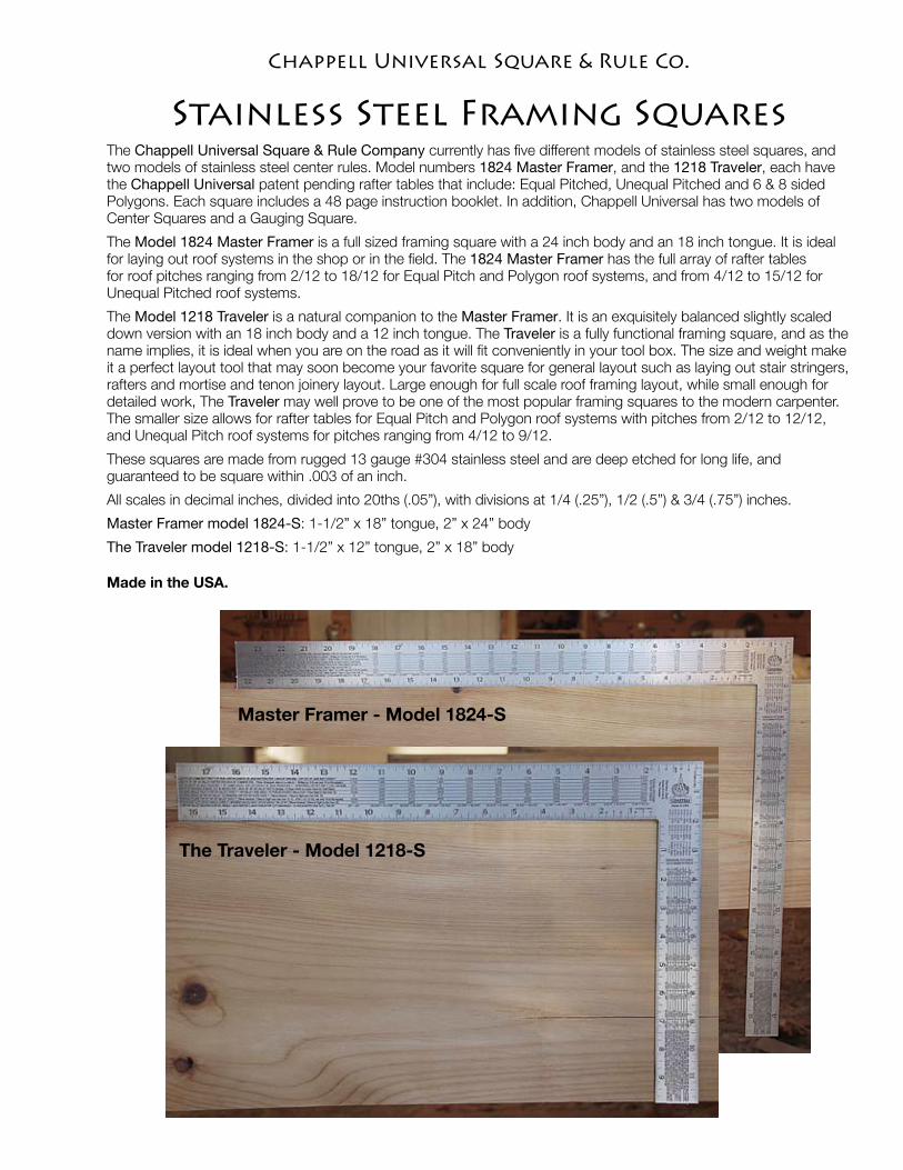
Master Framer - Model 1824-S
The Traveler - Model 1218-S
Stainless Steel Framing Squares The Chappell Universal Square & Rule Company currently has five different models of stainless steel squares, and two models of stainless steel center rules. Model numbers 1824 Master Framer, and the 1218 Traveler, each have the Chappell Universal patent pending rafter tables that include: Equal Pitched, Unequal Pitched and 6 & 8 sided Polygons. Each square includes a 48 page instruction booklet. In addition, Chappell Universal has two models of Center Squares and a Gauging Square.
The Model 1824 Master Framer is a full sized framing square with a 24 inch body and an 18 inch tongue. It is ideal for laying out roof systems in the shop or in the field. The 1824 Master Framer has the full array of rafter tables for roof pitches ranging from 2/12 to 18/12 for Equal Pitch and Polygon roof systems, and from 4/12 to 15/12 for Unequal Pitched roof systems.
The Model 1218 Traveler is a natural companion to the Master Framer. It is an exquisitely balanced slightly scaled down version with an 18 inch body and a 12 inch tongue. The Traveler is a fully functional framing square, and as the name implies, it is ideal when you are on the road as it will fit conveniently in your tool box. The size and weight make it a perfect layout tool that may soon become your favorite square for general layout such as laying out stair stringers, rafters and mortise and tenon joinery layout. Large enough for full scale roof framing layout, while small enough for detailed work, The Traveler may well prove to be one of the most popular framing squares to the modern carpenter. The smaller size allows for rafter tables for Equal Pitch and Polygon roof systems with pitches from 2/12 to 12/12, and Unequal Pitch roof systems for pitches ranging from 4/12 to 9/12.
These squares are made from rugged 13 gauge #304 stainless steel and are deep etched for long life, and guaranteed to be square within .003 of an inch.
All scales in decimal inches, divided into 20ths (.05”), with divisions at 1/4 (.25”), 1/2 (.5”) & 3/4 (.75”) inches.
Master Framer model 1824-S: 1-1/2” x 18” tongue, 2” x 24” body
The Traveler model 1218-S: 1-1/2” x 12” tongue, 2” x 18” body
Made in the USA.
Chappell Universal Square & Rule Co.
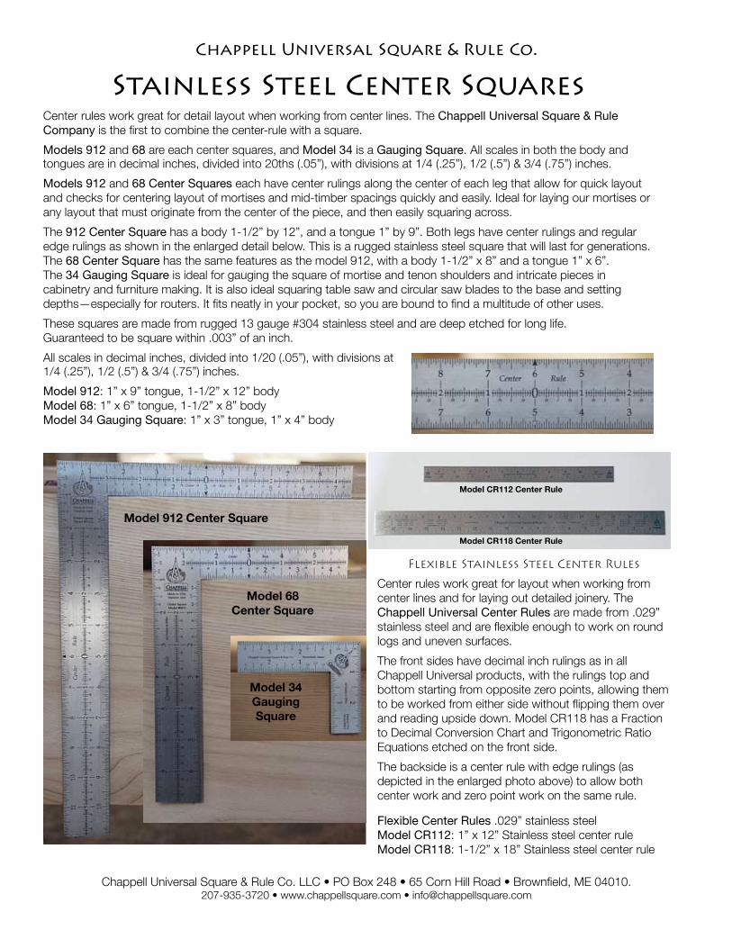
Model 912 Center Square
Model 68 Center Square
Model 34 Gauging Square
Stainless Steel Center SquaresCenter rules work great for detail layout when working from center lines. The Chappell Universal Square & Rule Company is the first to combine the center-rule with a square.
Models 912 and 68 are each center squares, and Model 34 is a Gauging Square. All scales in both the body and tongues are in decimal inches, divided into 20ths (.05”), with divisions at 1/4 (.25”), 1/2 (.5”) & 3/4 (.75”) inches.
Models 912 and 68 Center Squares each have center rulings along the center of each leg that allow for quick layout and checks for centering layout of mortises and mid-timber spacings quickly and easily. Ideal for laying our mortises or any layout that must originate from the center of the piece, and then easily squaring across.
The 912 Center Square has a body 1-1/2” by 12”, and a tongue 1” by 9”. Both legs have center rulings and regular edge rulings as shown in the enlarged detail below. This is a rugged stainless steel square that will last for generations. The 68 Center Square has the same features as the model 912, with a body 1-1/2” x 8” and a tongue 1” x 6”. The 34 Gauging Square is ideal for gauging the square of mortise and tenon shoulders and intricate pieces in cabinetry and furniture making. It is also ideal squaring table saw and circular saw blades to the base and setting depths—especially for routers. It fits neatly in your pocket, so you are bound to find a multitude of other uses.
These squares are made from rugged 13 gauge #304 stainless steel and are deep etched for long life. Guaranteed to be square within .003” of an inch.
All scales in decimal inches, divided into 1/20 (.05”), with divisions at 1/4 (.25”), 1/2 (.5”) & 3/4 (.75”) inches.
Model 912: 1” x 9” tongue, 1-1/2” x 12” bodyModel 68: 1” x 6” tongue, 1-1/2” x 8” bodyModel 34 Gauging Square: 1” x 3” tongue, 1” x 4” body
Chappell Universal Square & Rule Co. LLC • PO Box 248 • 65 Corn Hill Road • Brownfield, ME 04010. 207-935-3720 • www.chappellsquare.com • [email protected]
Chappell Universal Square & Rule Co.
Model CR112 Center Rule
Model CR118 Center Rule
Flexible Stainless Steel Center Rules
Center rules work great for layout when working from center lines and for laying out detailed joinery. The Chappell Universal Center Rules are made from .029” stainless steel and are flexible enough to work on round logs and uneven surfaces.
The front sides have decimal inch rulings as in all Chappell Universal products, with the rulings top and bottom starting from opposite zero points, allowing them to be worked from either side without flipping them over and reading upside down. Model CR118 has a Fraction to Decimal Conversion Chart and Trigonometric Ratio Equations etched on the front side.
The backside is a center rule with edge rulings (as depicted in the enlarged photo above) to allow both center work and zero point work on the same rule.
Flexible Center Rules .029” stainless steel Model CR112: 1” x 12” Stainless steel center ruleModel CR118: 1-1/2” x 18” Stainless steel center rule
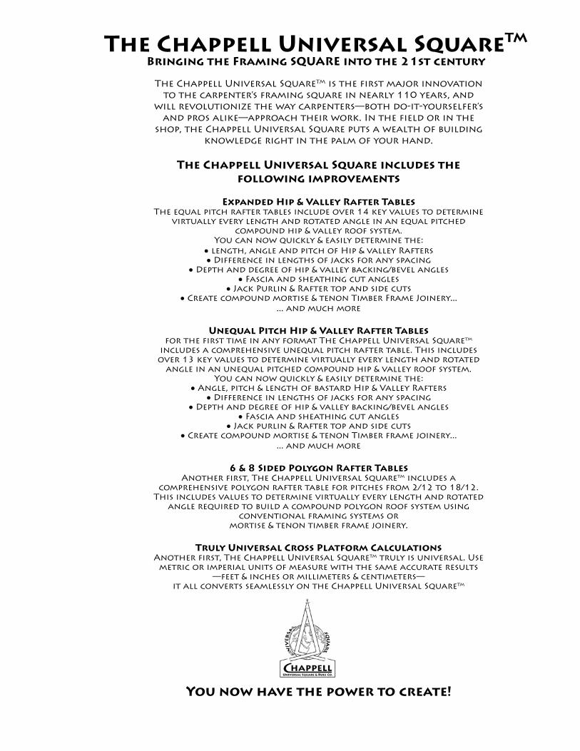
The Chappell Universal SquareTM is the first major innovation to the carpenter’s framing square in nearly 110 years, and
will revolutionize the way carpenters—both do-it-yourselfer’s and pros alike—approach their work. In the field or in the
shop, the Chappell Universal Square puts a wealth of building knowledge right in the palm of your hand.
The Chappell Universal Square includes the following improvements
Expanded Hip & Valley Rafter TablesThe equal pitch rafter tables include over 14 key values to determine
virtually every length and rotated angle in an equal pitched compound hip & valley roof system.
You can now quickly & easily determine the: • length, angle and pitch of Hip & valley Rafters• Difference in lengths of jacks for any spacing
• Depth and degree of hip & valley backing/bevel angles• Fascia and sheathing cut angles
• Jack Purlin & Rafter top and side cuts• Create compound mortise & tenon Timber Frame Joinery...
... and much more
Unequal Pitch Hip & Valley Rafter Tablesfor the first time in any format The Chappell Universal Squaretm
includes a comprehensive unequal pitch rafter table. This includes over 13 key values to determine virtually every length and rotated
angle in an unequal pitched compound hip & valley roof system. You can now quickly & easily determine the:
• Angle, pitch & length of bastard Hip & Valley Rafters • Difference in lengths of jacks for any spacing
• Depth and degree of hip & valley backing/bevel angles• Fascia and sheathing cut angles
• Jack purlin & Rafter top and side cuts • Create compound mortise & tenon Timber frame joinery...
... and much more
6 & 8 Sided Polygon Rafter TablesAnother first, The Chappell Universal Squaretm includes a
comprehensive polygon rafter table for pitches from 2/12 to 18/12. This includes values to determine virtually every length and rotated
angle required to build a compound polygon roof system using conventional framing systems or
mortise & tenon timber frame joinery.
Truly Universal Cross Platform CalculationsAnother first, The Chappell Universal Squaretm truly is universal. Use
metric or imperial units of measure with the same accurate results —feet & inches or millimeters & centimeters—
it all converts seamlessly on the Chappell Universal Squaretm
You now have the power to create!
The Chappell Universal SquareTM
Bringing the Framing SQUARE into the 21st century
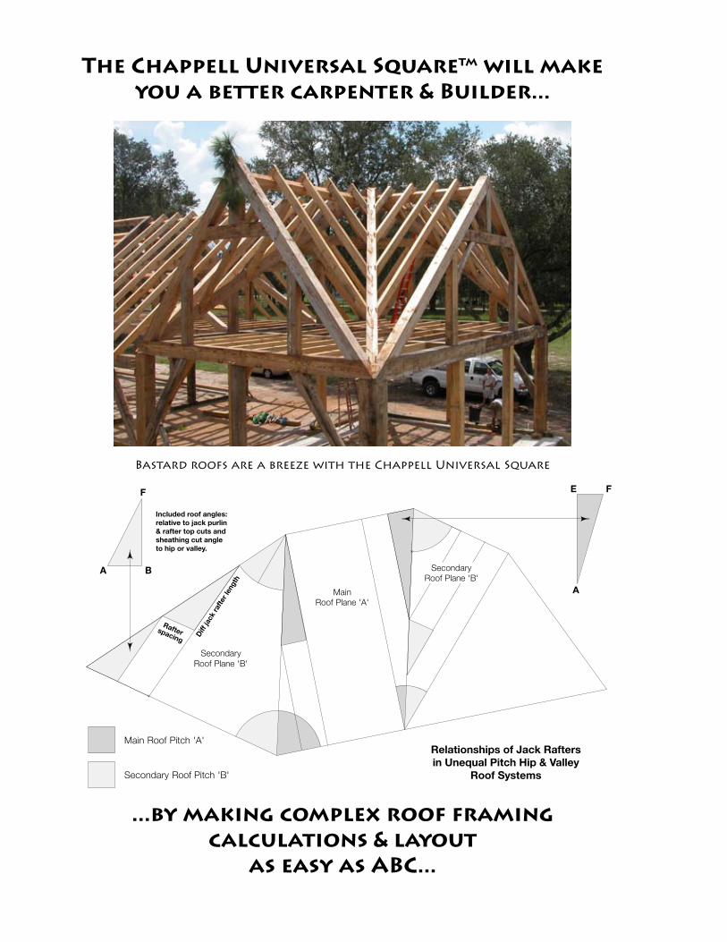
Main Roof Pitch 'A'
Secondary Roof Pitch 'B'
Main
Roof Plane 'A'
Secondary
Roof Plane 'B'
Secondary
Roof Plane 'B'
Relationships of Jack Rafters in Unequal Pitch Hip & Valley
Roof Systems
Included roof angles: relative to jack purlin & rafter top cuts and sheathing cut angle to hip or valley.
Diff
jack
rafte
r len
gth
Rafterspacing
F
BA
F
A
E
The Chappell Universal Squaretm will make you a better carpenter & Builder...
...by making complex roof framing calculations & layout
as easy as ABC...
Bastard roofs are a breeze with the Chappell Universal Square