Embed Size (px)
Citation preview

ACTAtek3 Manual
Version 1.0
Mar 29, 2010
ACTAtek Pte Ltd

ACTAtek Pte Limited
ACTAtek3 Manual 2
Revision History Revision Date Description Author
1.0 2010/03/29 Initial Release Cheong / Justin

ACTAtek Pte Limited
ACTAtek3 Manual 3
ACTAtek3 Manual Copyright 2004 - 2010 ACTAtek Pte Limited, All rights reserved.
No part of this document may be reproduced, transmitted, transcribed, stored in a retrieval system, or translated into any language, in any form or by any means, electronic, mechanical, magnetic, optical, chemical, manual or otherwise without the prior written permission of ACTAtek Pte Limited.
ACTAtek is a registered trademark of ACTAtek Pte Limited
All trademarks, registered trademarks, and service marks are the property of their respective owners.
ACTAtek Pte Limited
ACTAtek3 Manual 5
Table of Contents
Chapter 1. Introduction ................................................................................. 8
1.1. Purpose ................................................................................................... 8
1.2. Document Conventions ........................................................................... 8
1.3. Intended Audience and Reading Suggestion ........................................... 8
1.4. Software References for this document ................................................... 8
Chapter 2. Product Overview ....................................................................... 9
2.1. ACTAtek3 Model number ........................................................................ 9
2.1.1. Legend .............................................................................................................. 9
2.1.2. EXAMPLE ......................................................................................................... 9
2.2. Comparison between Fingerprint and Smart Card Models: .................... 10
2.3. Warranty Note ....................................................................................... 11
2.4. Setup Requirements .............................................................................. 12
2.4.1. Operating System (For access via Corporate Network) ................................. 12
2.4.2. Network Interface ............................................................................................ 12
2.4.3. Power Requirements ....................................................................................... 12
Chapter 3. ACTAtek3 Structure and Connections ...................................... 13
3.1. ACTAtek3TM
Internal Structure and Connections ................................... 13
3.2. Connection Details: ................................................................................ 14
3.2.1. JP18 ................................................................................................................ 14
3.2.2. JP20 ................................................................................................................ 14
3.2.3. J3 .................................................................................................................... 14
3.2.4. J4 .................................................................................................................... 14
3.2.5. JP17 ................................................................................................................ 14
3.2.6. JP19 ................................................................................................................ 14
3.2.7. J6 .................................................................................................................... 14
3.2.8. P4 .................................................................................................................... 14
3.2.9. J2 .................................................................................................................... 14
Chapter 4. Fingerprint Notes ...................................................................... 15
4.1. Introduction ............................................................................................ 15
4.2. Technical Information ............................................................................ 15
4.3. Good Image vs Bad Image .................................................................... 16
4.4. Fingerprint Enrollment & Authentication ................................................. 17
4.5. Fingerprint Enrollment: .......................................................................... 18
Chapter 5. ACTAtek3TM
Introduction .......................................................... 19
5.1. Introduction ............................................................................................ 19
5.2. LCD Module ........................................................................................... 20
5.3. Keypad Module ...................................................................................... 20
5.4. Fingerprint Scanner Module ................................................................... 21
Chapter 6. System Configuration ............................................................... 22
6.1. Login...................................................................................................... 22
6.2. Add User ............................................................................................... 24
ACTAtek Pte Limited
ACTAtek3 Manual 6
6.2.1. Adding A New User via Fingerprint ................................................................. 24
6.2.2. Adding A New User via Smart Card ................................................................ 26
6.2.3. Deleting A Smart card user ............................................................................. 27
6.2.4. Adding A New User via Password................................................................... 28
6.3. Error Messages ..................................................................................... 29
6.4. User Management ................................................................................. 31
6.4.1. User Management – Activating A User ........................................................... 31
6.4.2. User Management – Deactivating A User ....................................................... 31
6.4.3. User Management – Deleting A User ............................................................. 32
6.5. Auto Match ............................................................................................ 33
6.5.1. To Enable Auto Match ..................................................................................... 33
6.5.2. To Disable Auto Match .................................................................................... 34
6.6. Date & Time .......................................................................................... 35
6.6.1. To Modify the Date Settings ............................................................................ 35
6.6.2. To Modify the Time Settings ........................................................................... 36
6.7. IP Settings ............................................................................................. 36
6.7.1. IP Address Configuration ................................................................................ 37
6.7.2. Default Gateway Configuration ....................................................................... 37
6.7.3. DNS IP Configuration ...................................................................................... 38
6.7.4. Subnet Mask Configuration ............................................................................. 38
6.7.5. DHCP IP Configuration ................................................................................... 39
6.7.5.1. To Enable DHCP: ................................................................................. 39
6.7.5.2. To Disable DHCP: ................................................................................. 39
6.8. Terminal Settings ................................................................................... 40
6.8.1. Terminal Settings Function ............................................................................. 40
6.8.1.1. Fingerprint Security Level Settings ....................................................... 40
6.8.2. No. of FP Sample ............................................................................................ 41
6.8.3. Unlock Door .................................................................................................... 41
6.8.4. System Reboot ................................................................................................ 42
6.9. Reset ..................................................................................................... 42
6.9.1. Resetting the Event Log .................................................................................. 43
6.9.2. Resetting the User Database .......................................................................... 43
6.9.3. Factory Default ................................................................................................ 44
6.9.4. Web Port ......................................................................................................... 44
6.10. Exit ........................................................................................................ 44
Chapter 7. Web Administration .................................................................. 45
7.1. SSL Certification – Data Encryption ....................................................... 46
7.2. Terminal Status ..................................................................................... 47
Chapter 8. Super Administration Guide ...................................................... 48
8.1. Overview ................................................................................................ 48
8.1.1. Terminal .......................................................................................................... 49
8.1.2. User Administration ......................................................................................... 49
8.1.3. Access Control ................................................................................................ 49
8.1.4. Terminal Settings ............................................................................................ 49
8.1.5. Tools ............................................................................................................... 50
8.2. User Administration ............................................................................... 51
8.2.1. Attendance Report .......................................................................................... 51
8.2.2. View Event Log ............................................................................................... 53
8.2.2.1. Deleting Event Logs .............................................................................. 53
8.2.3. Adding An Event Log ....................................................................................... 53
8.2.4. View User List ................................................................................................. 54
8.2.4.1. To sort: .................................................................................................. 56
ACTAtek Pte Limited
ACTAtek3 Manual 7
8.2.4.2. To Delete/Deactivate/Activate Users: ................................................... 56
8.2.5. To Add New Users .......................................................................................... 57
8.2.5.1. To Add A New User: ............................................................................. 57
8.2.6. Departments .................................................................................................... 59
8.2.6.1. To Add a New Department: .................................................................. 59
8.2.6.2. To Modify Existing Departments: .......................................................... 59
8.2.6.3. To Delete Existing Departments: .......................................................... 59
8.2.7. User Messages ............................................................................................... 60
8.2.7.1. To Add a New Message: ....................................................................... 60
8.2.7.2. To Delete an existing User Message: ................................................... 61
8.3. Access Control ...................................................................................... 62
8.3.1. Access Groups ................................................................................................ 62
8.3.1.1. To View/Delete Existing Access Groups:.............................................. 62
8.3.1.2. To Add a New Access Group................................................................ 63
8.3.1.3. To Modify an Access Group .................................................................. 63
8.3.1.4. To Add a New Access Right ................................................................. 64
8.3.1.5. To Delete/ Modify Access Right ............................................................ 65
8.3.2. Triggers ........................................................................................................... 66
8.3.2.1. To View or Modify Existing Trigger List ................................................. 66
8.3.3. Holidays Settings ............................................................................................. 68
8.4. Terminal Settings ................................................................................... 69
8.4.1. Terminal Setup ................................................................................................ 69
8.4.2. Terminal List .................................................................................................... 71
8.4.3. Door Open Schedule ....................................................................................... 71
8.4.4. Bell Schedule .................................................................................................. 73
8.4.5. Terminal Clock ................................................................................................ 74
8.4.6. External Devices ............................................................................................. 75
8.5. Terminal ................................................................................................ 76
8.5.1. Backup System Data ....................................................................................... 76
8.5.2. Restore System Data ...................................................................................... 77
8.5.3. Firmware Upgrade .......................................................................................... 78
8.5.4. Download Report............................................................................................. 78
8.5.5. Capture Fingerprint ......................................................................................... 80
8.5.6. Remote Door Open ......................................................................................... 81
8.5.7. Reboot ............................................................................................................. 82
ACTAtek Pte Limited
ACTAtek3 Manual 8
Chapter 1. Introduction This sections explains the purpose and software references of the ACTAtek3.
1.1. Purpose
ACTAtek3 is an Access Control and Time Attendance product which allows users to access its record from any where, at any time and on any platform.
The primary objectives of this document is to provide advance features of ACTAtek3.
The secondary objectives of this document is to help the user to troubleshoot the ACTAtek3 within the shortest time. So, after read through this training manual, user will become more familiar with the functions and features of ACTAtek3.
1.2. Document Conventions
Input typed in a bold Arial font, and output using Arial. Comments are added in italics.
Command prompt and Source code looks like
main()
{
printf(“Hello World\n”);
}
1.3. Intended Audience and Reading Suggestion
This document is self-contained but assumes a basic knowledge of ACTAtek3. Advanced customers can use this document to enhance their usage in ACTAtek3, and resellers can use this document to enhance their customers needs.
1.4. Software References for this document
ACTAtek3 firmware: 1.31.1
ACTAtek Pte Limited
ACTAtek3 Manual 9
Chapter 2. Product Overview
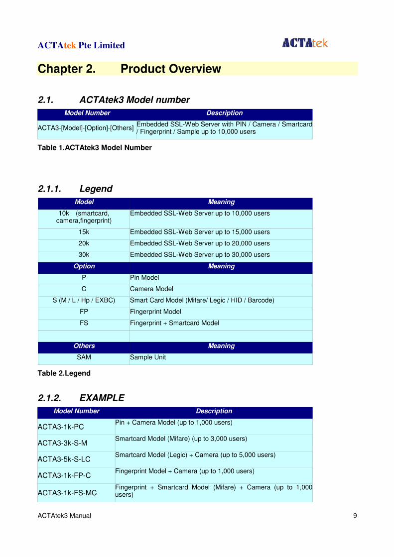
2.1. ACTAtek3 Model number
Model Number Description
ACTA3-[Model]-[Option]-[Others] Embedded SSL-Web Server with PIN / Camera / Smartcard / Fingerprint / Sample up to 10,000 users
Table 1.ACTAtek3 Model Number
2.1.1. Legend
Model Meaning
10k (smartcard, camera,fingerprint)
Embedded SSL-Web Server up to 10,000 users
15k Embedded SSL-Web Server up to 15,000 users
20k Embedded SSL-Web Server up to 20,000 users
30k Embedded SSL-Web Server up to 30,000 users
Option Meaning
P Pin Model
C Camera Model
S (M / L / Hp / EXBC) Smart Card Model (Mifare/ Legic / HID / Barcode)
FP Fingerprint Model
FS Fingerprint + Smartcard Model
Others Meaning
SAM Sample Unit
Table 2.Legend
2.1.2. EXAMPLE
Model Number Description
ACTA3-1k-PC Pin + Camera Model (up to 1,000 users)
ACTA3-3k-S-M Smartcard Model (Mifare) (up to 3,000 users)
ACTA3-5k-S-LC Smartcard Model (Legic) + Camera (up to 5,000 users)
ACTA3-1k-FP-C Fingerprint Model + Camera (up to 1,000 users)
ACTA3-1k-FS-MC Fingerprint + Smartcard Model (Mifare) + Camera (up to 1,000 users)
ACTAtek Pte Limited
ACTAtek3 Manual 10
ACTA3-1k-FS-LC-SAM Fingerprint + Smartcard Model (Legic) + Camera (up to 1,000users) – Sample unit
ACTA3-10k-S-LC ACTAtek 128 Meg Disk on Chip + Smart Card Model (Legic) + Camera (up to 10,000 users)
ACTA3-20k-FS-MC ACTAtek 128 Meg Disk on Chip + Fingerprint + Smart Card Model (Mifare) + Camera (up to 20,000 users)
Table 3.Example
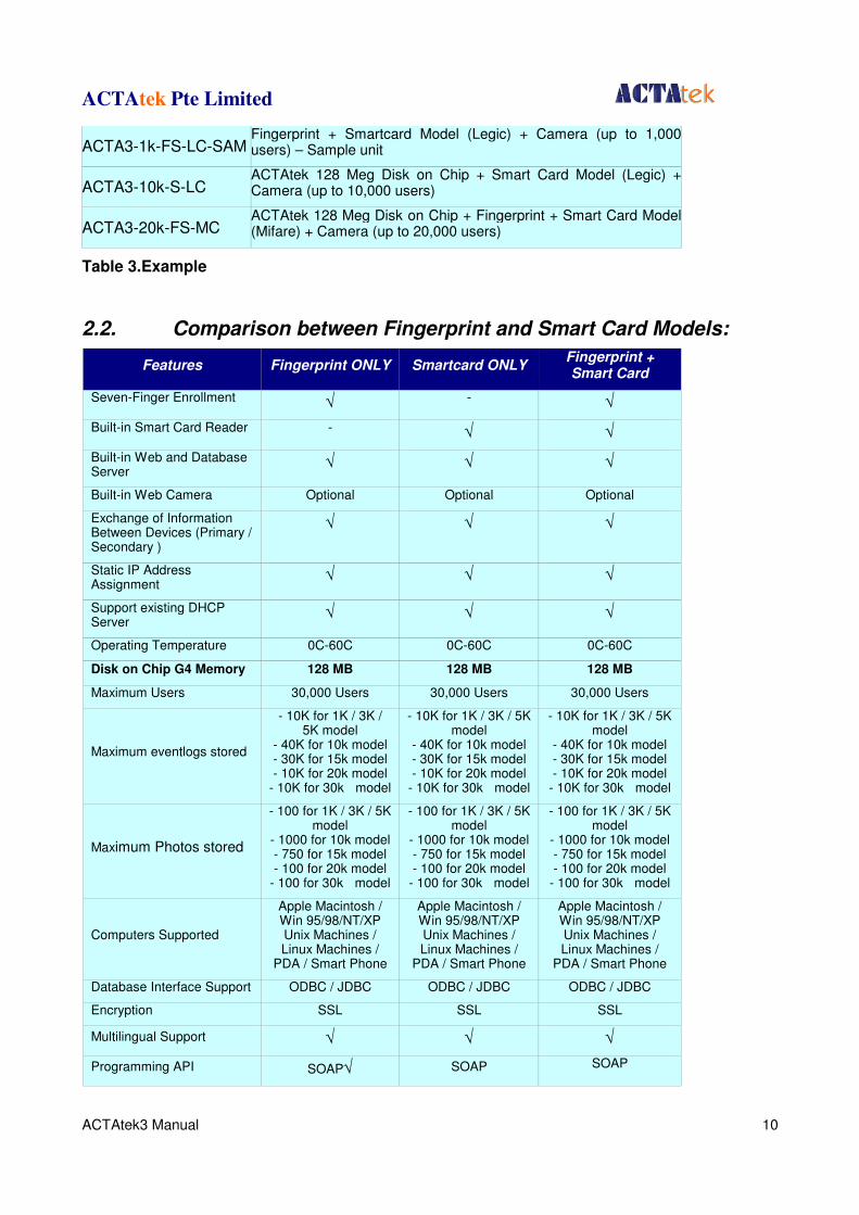
2.2. Comparison between Fingerprint and Smart Card Models:
Features Fingerprint ONLY Smartcard ONLY Fingerprint + Smart Card
Seven-Finger Enrollment √ - √
Built-in Smart Card Reader - √ √
Built-in Web and Database Server
√ √ √
Built-in Web Camera Optional Optional Optional
Exchange of Information Between Devices (Primary / Secondary )
√ √ √
Static IP Address Assignment
√ √ √
Support existing DHCP Server
√ √ √
Operating Temperature 0C-60C 0C-60C 0C-60C
Disk on Chip G4 Memory 128 MB 128 MB 128 MB
Maximum Users 30,000 Users 30,000 Users 30,000 Users
Maximum eventlogs stored
- 10K for 1K / 3K / 5K model
- 40K for 10k model - 30K for 15k model - 10K for 20k model
- 10K for 30k model
- 10K for 1K / 3K / 5K model
- 40K for 10k model - 30K for 15k model - 10K for 20k model
- 10K for 30k model
- 10K for 1K / 3K / 5K model
- 40K for 10k model - 30K for 15k model - 10K for 20k model
- 10K for 30k model
Maximum Photos stored
- 100 for 1K / 3K / 5K model
- 1000 for 10k model - 750 for 15k model - 100 for 20k model
- 100 for 30k model
- 100 for 1K / 3K / 5K model
- 1000 for 10k model - 750 for 15k model - 100 for 20k model
- 100 for 30k model
- 100 for 1K / 3K / 5K model
- 1000 for 10k model - 750 for 15k model - 100 for 20k model
- 100 for 30k model
Computers Supported
Apple Macintosh / Win 95/98/NT/XP Unix Machines / Linux Machines /
PDA / Smart Phone
Apple Macintosh / Win 95/98/NT/XP Unix Machines / Linux Machines /
PDA / Smart Phone
Apple Macintosh / Win 95/98/NT/XP Unix Machines / Linux Machines /
PDA / Smart Phone
Database Interface Support ODBC / JDBC ODBC / JDBC ODBC / JDBC
Encryption SSL SSL SSL
Multilingual Support √ √ √
Programming API SOAP√ SOAP SOAP
ACTAtek Pte Limited
ACTAtek3 Manual 11
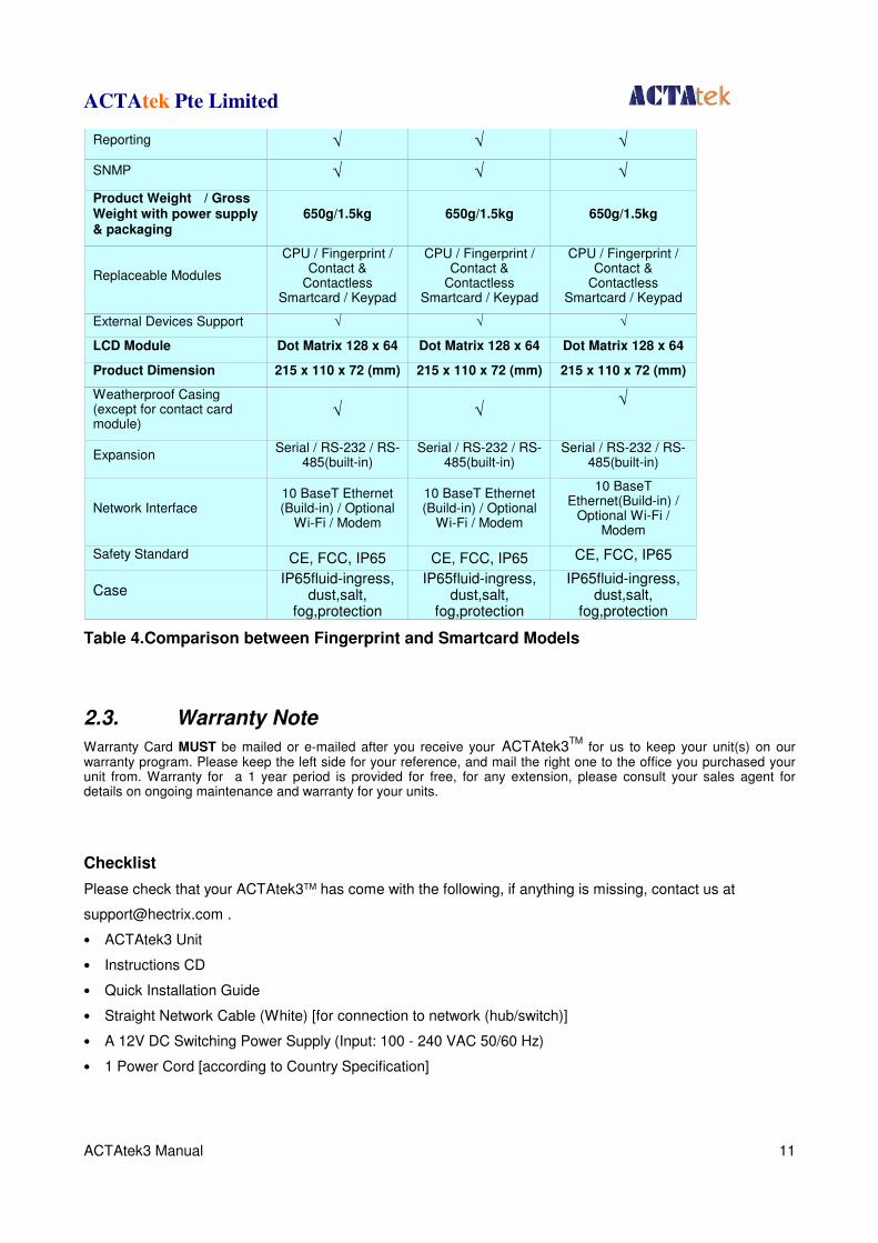
Reporting √ √ √
SNMP √ √ √
Product Weight / Gross Weight with power supply & packaging
650g/1.5kg 650g/1.5kg 650g/1.5kg
Replaceable Modules
CPU / Fingerprint / Contact &
Contactless Smartcard / Keypad
CPU / Fingerprint / Contact &
Contactless Smartcard / Keypad
CPU / Fingerprint / Contact &
Contactless Smartcard / Keypad
External Devices Support √ √ √
LCD Module Dot Matrix 128 x 64 Dot Matrix 128 x 64 Dot Matrix 128 x 64
Product Dimension 215 x 110 x 72 (mm) 215 x 110 x 72 (mm) 215 x 110 x 72 (mm)
Weatherproof Casing (except for contact card module)
√ √ √
Expansion Serial / RS-232 / RS-
485(built-in) Serial / RS-232 / RS-
485(built-in) Serial / RS-232 / RS-
485(built-in)
Network Interface 10 BaseT Ethernet (Build-in) / Optional
Wi-Fi / Modem
10 BaseT Ethernet (Build-in) / Optional
Wi-Fi / Modem
10 BaseT Ethernet(Build-in) /
Optional Wi-Fi / Modem
Safety Standard CE, FCC, IP65 CE, FCC, IP65 CE, FCC, IP65
Case IP65fluid-ingress,
dust,salt, fog,protection
IP65fluid-ingress, dust,salt,
fog,protection
IP65fluid-ingress, dust,salt,
fog,protection
Table 4.Comparison between Fingerprint and Smartcard Models
2.3. Warranty Note
Warranty Card MUST be mailed or e-mailed after you receive your ACTAtek3TM
for us to keep your unit(s) on our warranty program. Please keep the left side for your reference, and mail the right one to the office you purchased your unit from. Warranty for a 1 year period is provided for free, for any extension, please consult your sales agent for details on ongoing maintenance and warranty for your units.
Checklist
Please check that your ACTAtek3TM has come with the following, if anything is missing, contact us at
• ACTAtek3 Unit
• Instructions CD
• Quick Installation Guide
• Straight Network Cable (White) [for connection to network (hub/switch)]
• A 12V DC Switching Power Supply (Input: 100 - 240 VAC 50/60 Hz)
• 1 Power Cord [according to Country Specification]
ACTAtek Pte Limited
ACTAtek3 Manual 12
2.4. Setup Requirements
2.4.1. Operating System (For access via Corporate Network)
• Windows 95/98/2000/NT/XP/Vista/Win 7
• Linux Machines
• Unix Machine
• Apple Macintosh
• PDA
• Smart Phone
2.4.2. Network Interface
• 10 BaseT Ethernet (built-in) • RJ45 Cabling for Network Connectivity.
• Straight Network Cable (White cable, to connect to your corporate network via Hub/Switch)
• Crossover Network Cable (Black cable, to connect directly to your Computer)
2.4.3. Power Requirements
• A 12V DC switching power supply (provided), please do not substitute our power supply from another one
• Each 12V power supply can only support ONE ACTAtek3, failing to do so will void the warranty.
ACTAtek Pte Limited
ACTAtek3 Manual 13
Chapter 3. ACTAtek3 Structure and Connections
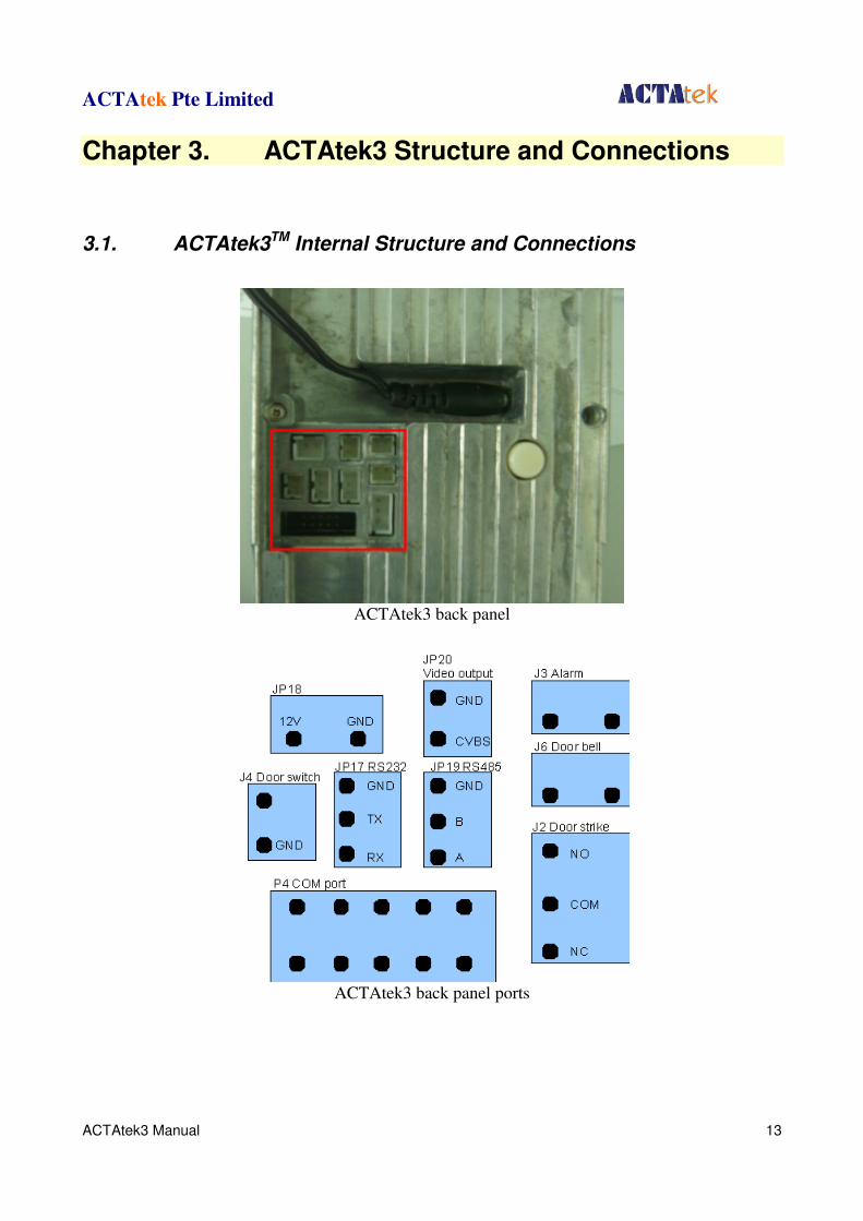
3.1. ACTAtek3TM Internal Structure and Connections
ACTAtek3 back panel
ACTAtek3 back panel ports

ACTAtek Pte Limited
ACTAtek3 Manual 14
3.2. Connection Details:
3.2.1. JP18
• Used for 12V 1A power output.
3.2.2. JP20
• Used for video output. The output can be connected to any television or monitors with AV input.
3.2.3. J3
• Used for alarm purpose, when the case of the unit is open, the alarm will be triggered. When it is triggered, the two pins will be short circuit.
3.2.4. J4
• Used as door switch1.
3.2.5. JP17
• Used for debug or connecting external IO board.
3.2.6. JP19
• Used for connecting external card readers.
3.2.7. J6
• Working as a doorbell. If doorbell key on the front panel is pressed or it is enabled from the web page the two pins will be short circuit.
3.2.8. P4
• Used to connect external modem.
3.2.9. J2
• Used for door strike. NO (normal open) is open circuit normally, and will be short circuit when door is open. NC (normal close) is short circuit normally, and will be open circuit when door is open.
ACTAtek Pte Limited
ACTAtek3 Manual 15
Chapter 4. Fingerprint Notes
Chapter 4. Fingerprint Notes
4.1. Introduction
ACTAtek3 TM uses latest Optical Scanning technology with its own algorithms and matching calculations, a step above other sensors in the market.
It must be emphasized that to get an accurate enrollment and quick authentication each time a fingerprint is presented, the fingerprint placement must be towards the center of the scanner. Placing your finger far from the center position of the sensor will increase the rejection rate.
Finger Rotation should be kept to a minimum during enrollment and verification.
When enrolling, place the finger on the sensor where the entire core can clearly be seen by the scanner.
A good image is critical for the overall performance of the fingerprint scanner. Any deviation from a good image, either by placing the finger far away from the scanner, or by applying too much pressure or not locating it in the CENTER of the scanner, will cause the scanner’s rejection rate to rise. Read below on how to get a good image for your enrollment/authentication.
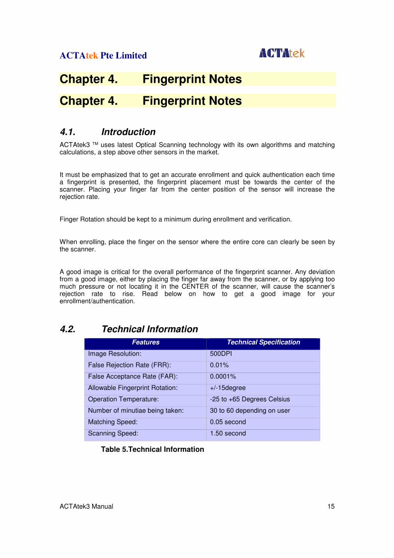
4.2. Technical Information
Features Technical Specification
Image Resolution: 500DPI
False Rejection Rate (FRR): 0.01%
False Acceptance Rate (FAR): 0.0001%
Allowable Fingerprint Rotation: +/-15degree
Operation Temperature: -25 to +65 Degrees Celsius
Number of minutiae being taken: 30 to 60 depending on user
Matching Speed: 0.05 second
Scanning Speed: 1.50 second
Table 5.Technical Information
ACTAtek Pte Limited
ACTAtek3 Manual 16
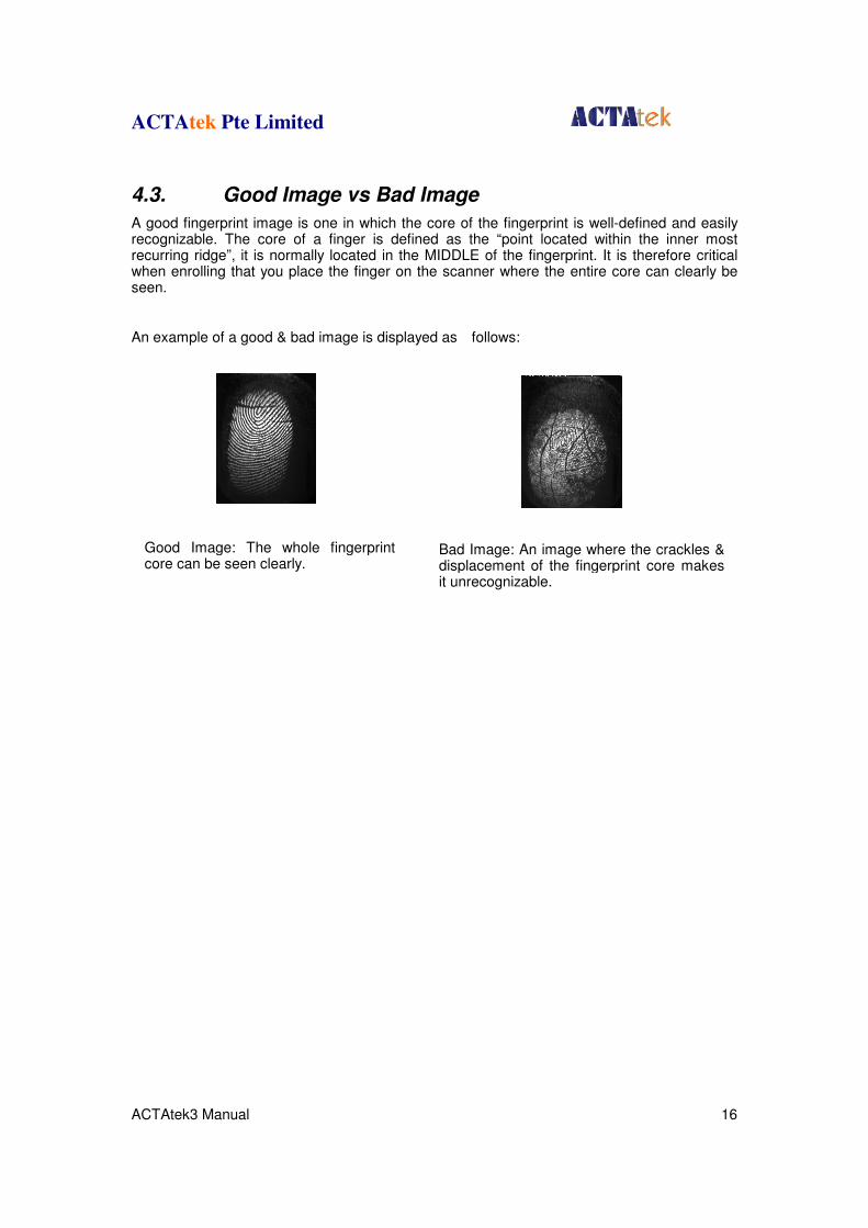
4.3. Good Image vs Bad Image
A good fingerprint image is one in which the core of the fingerprint is well-defined and easily recognizable. The core of a finger is defined as the “point located within the inner most recurring ridge”, it is normally located in the MIDDLE of the fingerprint. It is therefore critical when enrolling that you place the finger on the scanner where the entire core can clearly be seen.
An example of a good & bad image is displayed as follows:
Bad Image: An image where the crackles & displacement of the fingerprint core makes it unrecognizable.
Good Image: The whole fingerprint core can be seen clearly.
ACTAtek Pte Limited
ACTAtek3 Manual 17
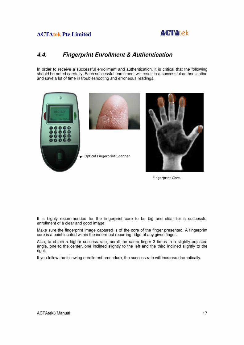
4.4. Fingerprint Enrollment & Authentication
In order to receive a successful enrollment and authentication, it is critical that the following should be noted carefully. Each successful enrollment will result in a successful authentication and save a lot of time in troubleshooting and erroneous readings.
It is highly recommended for the fingerprint core to be big and clear for a successful enrollment of a clear and good image.
Make sure the fingerprint image captured is of the core of the finger presented. A fingerprint core is a point located within the innermost recurring ridge of any given finger.
Also, to obtain a higher success rate, enroll the same finger 3 times in a slightly adjusted angle, one to the center, one inclined slightly to the left and the third inclined slightly to the right.
If you follow the following enrollment procedure, the success rate will increase dramatically.
Optical Fingerprint Scanner
Fingerprint Core.

ACTAtek Pte Limited
ACTAtek3 Manual 18
4.5. Fingerprint Enrollment:
Step 1: Place the center of any one finger directly above the sensor right in the center, as shown below:
Step 2: Place the center of the same finger (enrolled in Step 1), slightly aligned to the left.
Step 3: Place the center of the same finger, slightly aligned to the right.
After each placement, wait for the message “Template Stored” on the LCD screen to appear, and then remove your finger and press “Enter/Return” to enroll the second or third finger(s).
If you have any questions regarding the enrollment procedure, e-mail us at [email protected] .
ACTAtek Pte Limited
ACTAtek3 Manual 19
Chapter 5. ACTAtek3TM Introduction
Chapter 5. ACTAtek3TM Introduction
5.1. Introduction
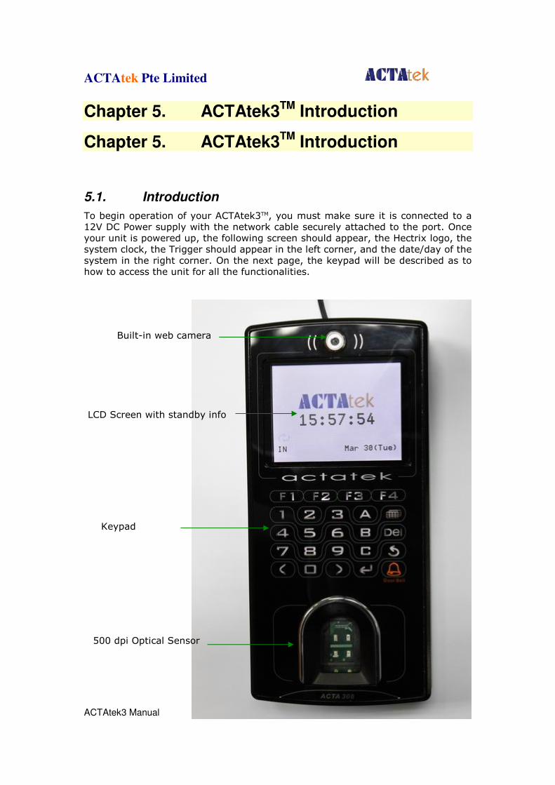
To begin operation of your ACTAtek3TM, you must make sure it is connected to a 12V DC Power supply with the network cable securely attached to the port. Once your unit is powered up, the following screen should appear, the Hectrix logo, the system clock, the Trigger should appear in the left corner, and the date/day of the system in the right corner. On the next page, the keypad will be described as to how to access the unit for all the functionalities.
Built-in web camera
LCD Screen with standby info
Keypad
500 dpi Optical Sensor
ACTAtek Pte Limited
ACTAtek3 Manual 20
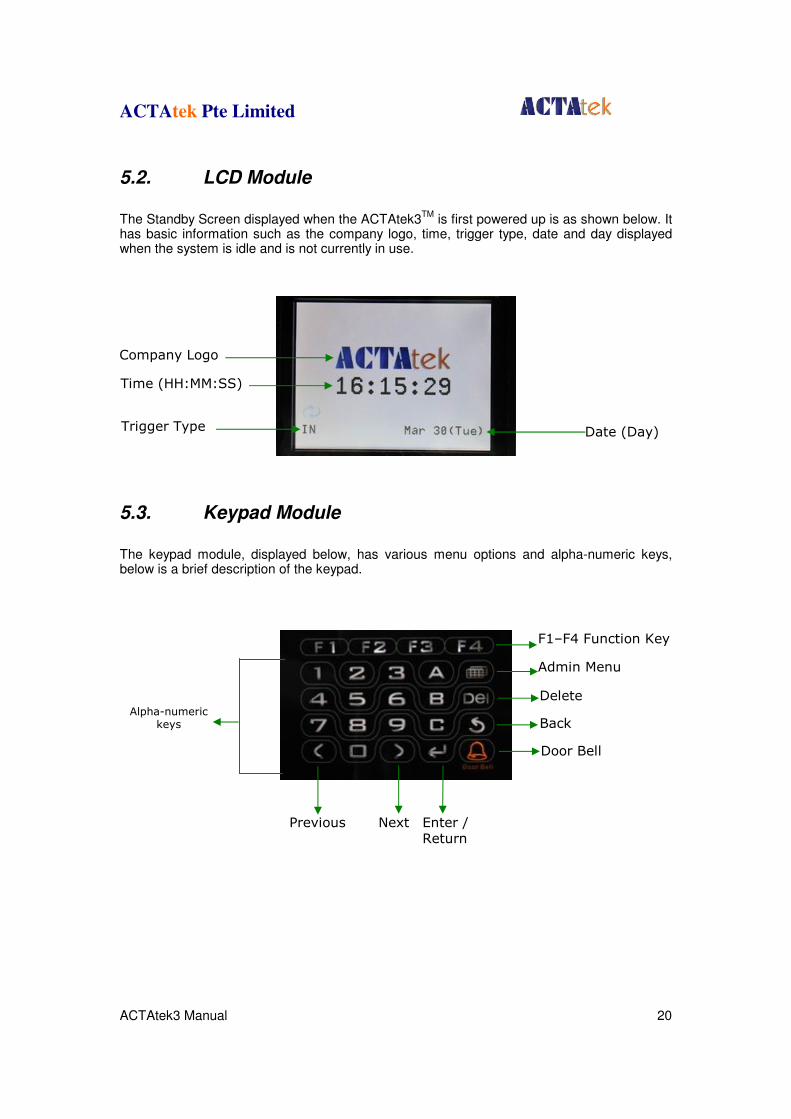
5.2. LCD Module
The Standby Screen displayed when the ACTAtek3
TM is first powered up is as shown below. It
has basic information such as the company logo, time, trigger type, date and day displayed when the system is idle and is not currently in use.
5.3. Keypad Module
The keypad module, displayed below, has various menu options and alpha-numeric keys, below is a brief description of the keypad.
Company Logo
Time (HH:MM:SS)
Trigger Type Date (Day)
Alpha-numeric keys
Admin Menu
Back
Enter / Return
Door Bell
Previous Next
Delete
F1–F4 Function Key

ACTAtek Pte Limited
ACTAtek3 Manual 21
5.4. Fingerprint Scanner Module
The biometric fingerprint module uses optical scanner technology with a 500 dpi resolution and it can be accessed either with a 1:1 authentication or 1:M authentication. The 1:M authentication, although convenient, has its limitation in the maximum number of users.
With any database, the more users in the system, the slower the authentication & verification time of the unit since the system has to check its entire database for that 1 specific fingerprint for authentication. It is therefore highly recommended for users to key in their ID, and then presents their fingerprint for a much quicker & accurate verification process.
The steps for a successful enrollment have been discussed earlier in the Fingerprint Notes section, for more information on the scanner and its technology; please refer to Chapter 3 on Fingerprint Notes.
ACTAtek Pte Limited
ACTAtek3 Manual 22
Chapter 6. System Configuration
6.1. Login
Logging In to the ACTAtek3 TM Admin System
There are two ways for a Super Administrator to log in to the ACTAtek3 system, one by fingerprint, and two by password. To login via fingerprint, do read up on the fingerprint enrollment procedure and follow the below steps to login.
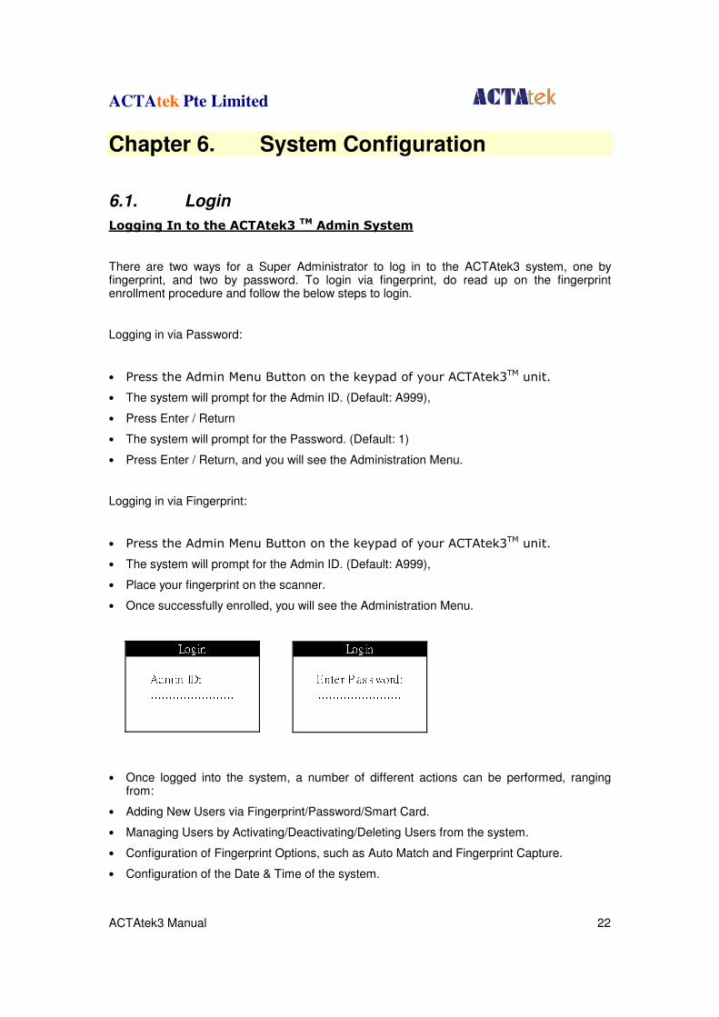
Logging in via Password:
• Press the Admin Menu Button on the keypad of your ACTAtek3TM unit.
• The system will prompt for the Admin ID. (Default: A999),
• Press Enter / Return
• The system will prompt for the Password. (Default: 1)
• Press Enter / Return, and you will see the Administration Menu.
Logging in via Fingerprint:
• Press the Admin Menu Button on the keypad of your ACTAtek3TM unit.
• The system will prompt for the Admin ID. (Default: A999),
• Place your fingerprint on the scanner.
• Once successfully enrolled, you will see the Administration Menu.
• Once logged into the system, a number of different actions can be performed, ranging
from:
• Adding New Users via Fingerprint/Password/Smart Card.
• Managing Users by Activating/Deactivating/Deleting Users from the system.
• Configuration of Fingerprint Options, such as Auto Match and Fingerprint Capture.
• Configuration of the Date & Time of the system.
LoginEnter P as s word:.......................LoginAdmin ID: .......................

ACTAtek Pte Limited
ACTAtek3 Manual 23
• Managing the network settings, including IP assignment, Subnet Mask, DNS, and so on.
• Resetting the system and other miscellaneous terminal settings can also be done.
Each of these steps will be discussed in detail in the following sections, starting from Adding a new user to Exiting from the system.
Changing the Default ID & Password: The first thing to do with the unit is to change the Administrator ID & password, to do so:
1. Log in to the web interface using a web browser. (Make sure the ACTAtek3TM
is connected to the network)
2. Default ID: A999, Default Password: 1, Super Administrator, and click OK
3. Go to “View User List”, click on the ID “A999”.
4. Enter the new Administrator ID, and Password, and click “Modify”. (The name and other details can also be changed here either now or later)
ACTAtek Pte Limited
ACTAtek3 Manual 24
6.2. Add User
6.2.1. Adding A New User via Fingerprint
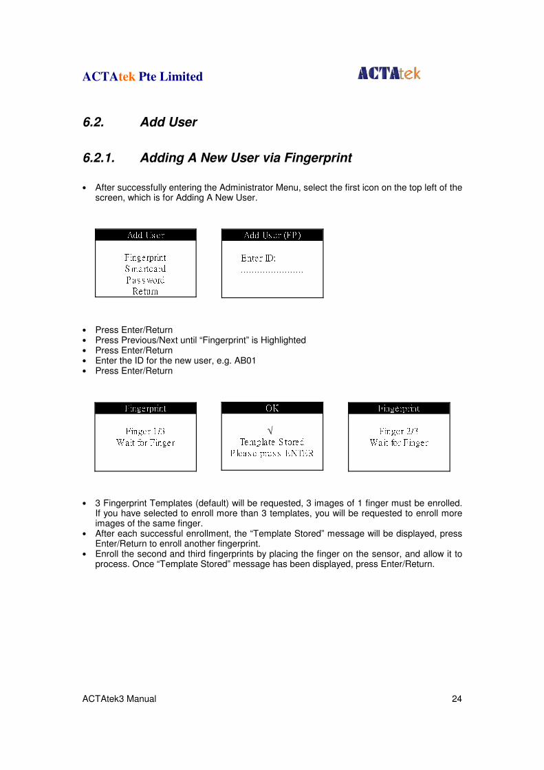
• After successfully entering the Administrator Menu, select the first icon on the top left of the
screen, which is for Adding A New User.
• Press Enter/Return • Press Previous/Next until “Fingerprint” is Highlighted • Press Enter/Return • Enter the ID for the new user, e.g. AB01 • Press Enter/Return
• 3 Fingerprint Templates (default) will be requested, 3 images of 1 finger must be enrolled.
If you have selected to enroll more than 3 templates, you will be requested to enroll more images of the same finger.
• After each successful enrollment, the “Template Stored” message will be displayed, press Enter/Return to enroll another fingerprint.
• Enroll the second and third fingerprints by placing the finger on the sensor, and allow it to process. Once “Template Stored” message has been displayed, press Enter/Return.
Add Us er (FP )Enter ID: .......................
FingerprintFinger 1/3Wait for Finger FingerprintFinger 2/3Wait for Finger
Add Us erFingerprintS martcardP as s wordReturnOKTempla te S toredP leas e pres s ENTER√

ACTAtek Pte Limited
ACTAtek3 Manual 25
• After successful enrollment of the third fingerprint, the message “User Added” will be
displayed. • Press Enter/Return to add another user, or Press the Menu button to go back to the
Administrator Menu Screen, or hit Back twice to exit from the system.
FingerprintFinger 3/3Wait for FingerOKTempla te S toredP leas e pres s ENTER√
Comple teUs er AddedP leas e pres s ENTER√
ACTAtek Pte Limited
ACTAtek3 Manual 26
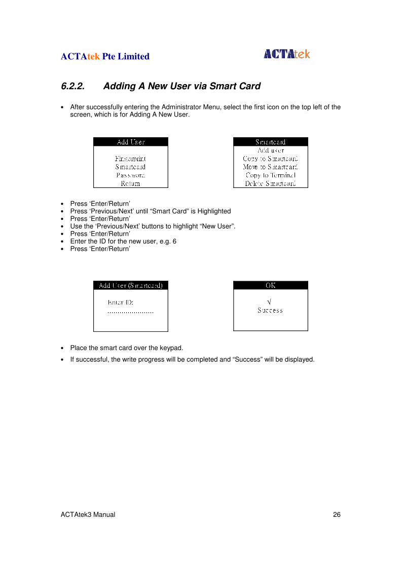
6.2.2. Adding A New User via Smart Card
• After successfully entering the Administrator Menu, select the first icon on the top left of the
screen, which is for Adding A New User.
• Press ‘Enter/Return’ • Press ‘Previous/Next’ until “Smart Card” is Highlighted • Press ‘Enter/Return’ • Use the ‘Previous/Next’ buttons to highlight “New User”. • Press ‘Enter/Return’ • Enter the ID for the new user, e.g. 6 • Press ‘Enter/Return’
• Place the smart card over the keypad.
• If successful, the write progress will be completed and “Success” will be displayed.
Add Us er (S martcard)Enter ID: .......................
S martcardAdd us erCopy to S martcardMove to S martcardCopy to Termina lDele te S martcardAdd Us erFingerprintS martcardP as s wordReturn
OKS ucces s√
ACTAtek Pte Limited
ACTAtek3 Manual 27
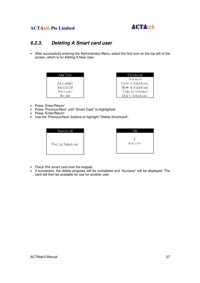
6.2.3. Deleting A Smart card user
• After successfully entering the Administrator Menu, select the first icon on the top left of the
screen, which is for Adding A New User.
• Press ‘Enter/Return’ • Press ‘Previous/Next’ until “Smart Card” is Highlighted • Press ‘Enter/Return’ • Use the ‘Previous/Next’ buttons to highlight “Delete Smartcard”.
• Place the smart card over the keypad. • If successful, the delete progress will be completed and “Success” will be displayed. The
card will then be available for use for another user.
S martcardWait for S martcard
Add Us erFingerprintS martcardP as s wordReturnS martcardAdd us erCopy to S martcardMove to S martcardCopy to Termina lDele te S martcard
OKS ucces s√
ACTAtek Pte Limited
ACTAtek3 Manual 28
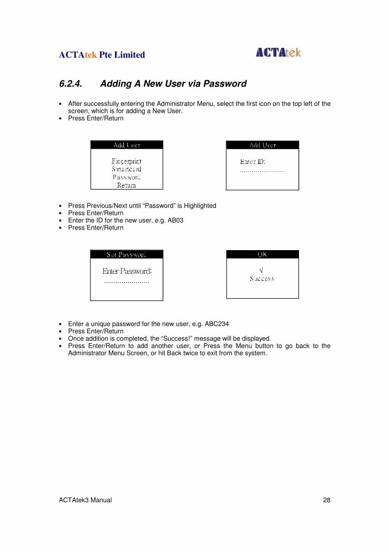
6.2.4. Adding A New User via Password
• After successfully entering the Administrator Menu, select the first icon on the top left of the
screen, which is for adding a New User. • Press Enter/Return
• Press Previous/Next until “Password” is Highlighted • Press Enter/Return • Enter the ID for the new user, e.g. AB03 • Press Enter/Return
• Enter a unique password for the new user, e.g. ABC234 • Press Enter/Return • Once addition is completed, the “Success!” message will be displayed. • Press Enter/Return to add another user, or Press the Menu button to go back to the
Administrator Menu Screen, or hit Back twice to exit from the system.
Add Us erEnte r ID: .......................S et P as s word
Enter Password:.......................
Add Us erFingerprintS martcardP as s wordReturnOKS ucces s√
ACTAtek Pte Limited
ACTAtek3 Manual 29
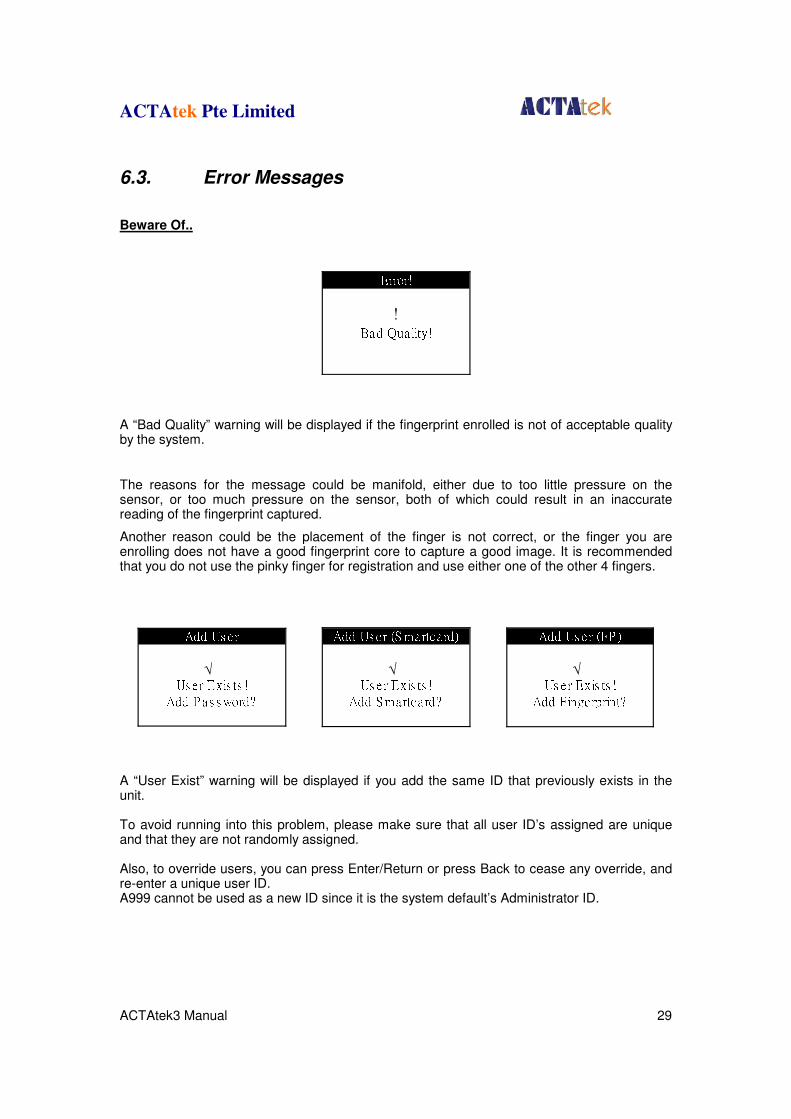
6.3. Error Messages
Beware Of..
A “Bad Quality” warning will be displayed if the fingerprint enrolled is not of acceptable quality by the system.
The reasons for the message could be manifold, either due to too little pressure on the sensor, or too much pressure on the sensor, both of which could result in an inaccurate reading of the fingerprint captured.
Another reason could be the placement of the finger is not correct, or the finger you are enrolling does not have a good fingerprint core to capture a good image. It is recommended that you do not use the pinky finger for registration and use either one of the other 4 fingers.
A “User Exist” warning will be displayed if you add the same ID that previously exists in the unit. To avoid running into this problem, please make sure that all user ID’s assigned are unique and that they are not randomly assigned. Also, to override users, you can press Enter/Return or press Back to cease any override, and re-enter a unique user ID. A999 cannot be used as a new ID since it is the system default’s Administrator ID.
Error!!Bad Quality!
Add Us erUs er Exis ts !Add P as s word?√
Add Us er (S martcard)Us er Exis ts !Add S martcard?√
Add Us er (FP )Us er Exis ts !Add Fingerprint?√
ACTAtek Pte Limited
ACTAtek3 Manual 30
1. Access Denied This message will be displayed when and if the user provides invalid login information, such as invalid ID, password, fingerprint or smart card.
2. Unauthorized This message will be displayed when the user tries to login during an unauthorized time period. (For information on Access groups and time settings, please refer to P. 31). In addition, if users do not have access to a particular terminal, and they try to access it, they will receive the “Unauthorized” message.
3. Primary Offine Message will be displayed at the secondary unit and its Primary is unreachable. The secondary unit’s LCD will continuously display “Primary Offline” and beep. The message will disappear as soon as the secondary can access primary unit. 4. Failed (to join Primary unit) Failed -1: Primary unreachable, wrong Primary IP address. Failed -2: Incompatible Firmware or Fingerprint module version. Failed -9: Timeout
ACTAtek Pte Limited
ACTAtek3 Manual 31
6.4. User Management
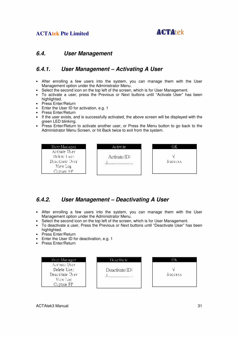
6.4.1. User Management – Activating A User
• After enrolling a few users into the system, you can manage them with the User
Management option under the Administrator Menu. • Select the second icon on the top left of the screen, which is for User Management. • To activate a user, press the Previous or Next buttons until “Activate User” has been
highlighted. • Press Enter/Return • Enter the User ID for activation, e.g. 1 • Press Enter/Return • If the user exists, and is successfully activated, the above screen will be displayed with the
green LED blinking. • Press Enter/Return to activate another user, or Press the Menu button to go back to the
Administrator Menu Screen, or hit Back twice to exit from the system.
6.4.2. User Management – Deactivating A User
• After enrolling a few users into the system, you can manage them with the User
Management option under the Administrator Menu. • Select the second icon on the top left of the screen, which is for User Management. • To deactivate a user, Press the Previous or Next buttons until “Deactivate User” has been
highlighted. • Press Enter/Return • Enter the User ID for deactivation, e.g. 1 • Press Enter/Return
Activa teActivate ID:.1.....................
Deactiva teDeactivate ID:.1.....................
Us er ManagerActiva te Us erDele te Us erDeac tivate Us erView LogCapture FP
Us er ManagerActiva te Us erDele te Us erDeac tivate Us erView LogCapture FP
OKS ucces s√
OKS ucces s√
ACTAtek Pte Limited
ACTAtek3 Manual 32
• If the user exists, and is successfully deactivated, the above screen will be displayed with the green LED blinking.
• Press Enter/Return to deactivate another user, or Press the Menu button to go back to the Administrator Menu Screen, or hit Back twice to exit from the system.
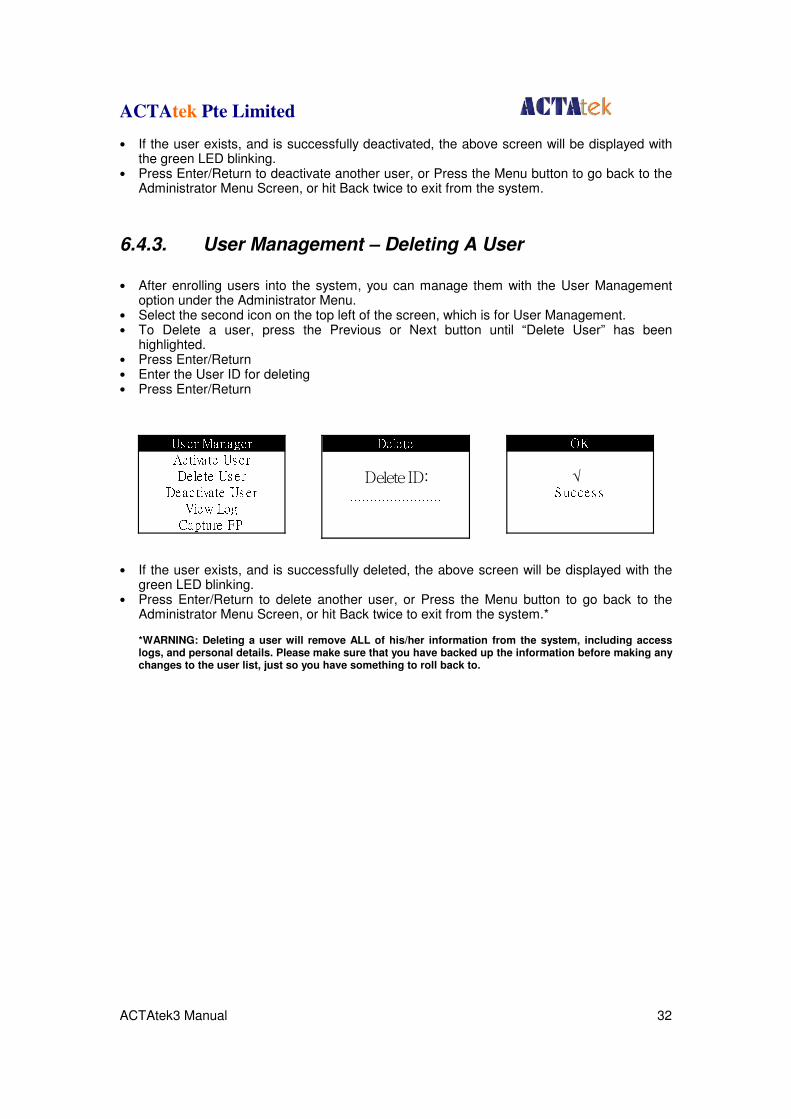
6.4.3. User Management – Deleting A User
• After enrolling users into the system, you can manage them with the User Management
option under the Administrator Menu. • Select the second icon on the top left of the screen, which is for User Management. • To Delete a user, press the Previous or Next button until “Delete User” has been
highlighted. • Press Enter/Return • Enter the User ID for deleting • Press Enter/Return
• If the user exists, and is successfully deleted, the above screen will be displayed with the green LED blinking.
• Press Enter/Return to delete another user, or Press the Menu button to go back to the Administrator Menu Screen, or hit Back twice to exit from the system.*
*WARNING: Deleting a user will remove ALL of his/her information from the system, including access logs, and personal details. Please make sure that you have backed up the information before making any changes to the user list, just so you have something to roll back to.
Dele teDelete ID:.......................Us er ManagerActiva te Us erDele te Us erDeac tivate Us erView LogCapture FP
OKS ucces s√
ACTAtek Pte Limited
ACTAtek3 Manual 33
6.5. Auto Match
Auto Match – Enable/Disable
After enrolling users into the system via fingerprint, Auto Match may be enabled for individual users. The primary function of Auto Match is to allow users to access the system without inputting their ID first. All they need to do to gain access is to place their fingers on the scanner and let the ACTAtek3
TM do the rest. Verification is quicker if few people are enrolled
into the system, and if few people are allowed to use the Auto Match feature. It is highly recommended that Auto match be limited in use and if used for all users, it should be understood that the verification time will be longer than if you input your ID and then fingerprint. Authentication methods are discussed in earlier sections; please refer to Section 8 on P.18 for more information on authentication & verification of ACTAtek3
TM.
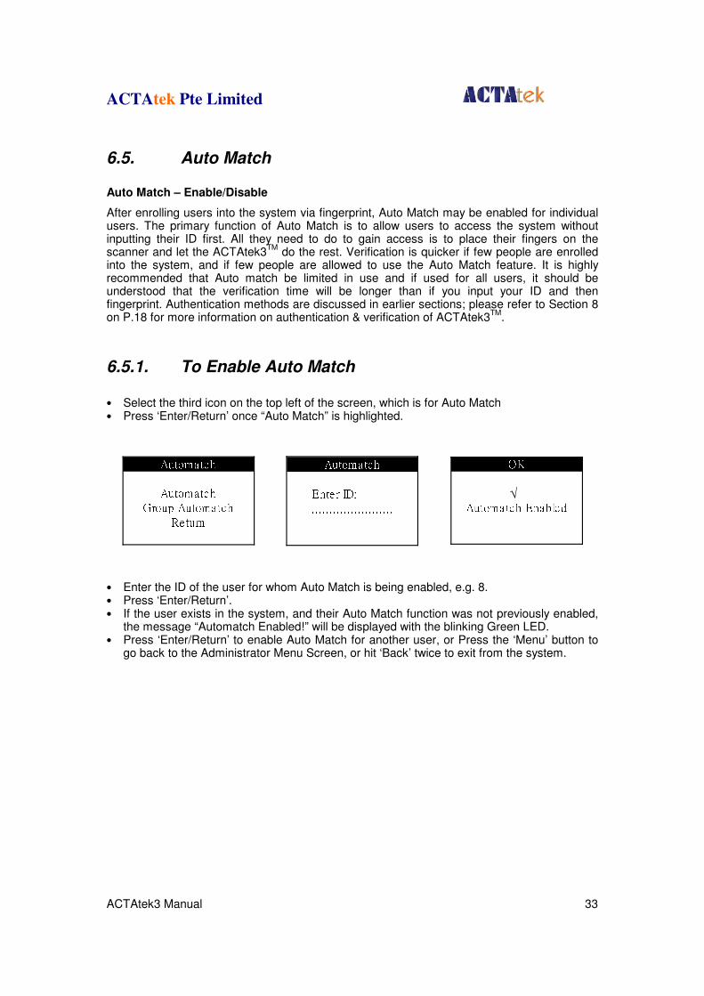
6.5.1. To Enable Auto Match
• Select the third icon on the top left of the screen, which is for Auto Match • Press ‘Enter/Return’ once “Auto Match” is highlighted.
• Enter the ID of the user for whom Auto Match is being enabled, e.g. 8. • Press ‘Enter/Return’. • If the user exists in the system, and their Auto Match function was not previously enabled,
the message “Automatch Enabled!” will be displayed with the blinking Green LED. • Press ‘Enter/Return’ to enable Auto Match for another user, or Press the ‘Menu’ button to
go back to the Administrator Menu Screen, or hit ‘Back’ twice to exit from the system.
AutomatchEnter ID: .......................AutomatchAutomatchGroup AutomatchReturn OKAutomatch Enabled√
ACTAtek Pte Limited
ACTAtek3 Manual 34
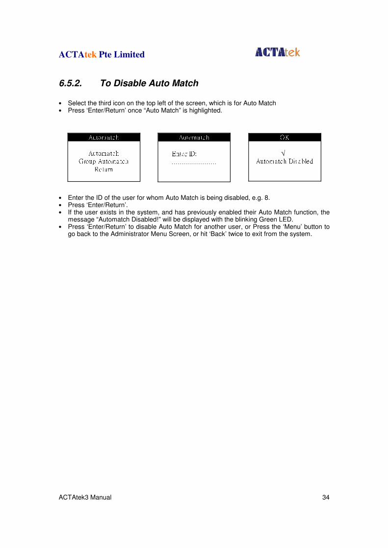
6.5.2. To Disable Auto Match
• Select the third icon on the top left of the screen, which is for Auto Match • Press ‘Enter/Return’ once “Auto Match” is highlighted.
• Enter the ID of the user for whom Auto Match is being disabled, e.g. 8. • Press ‘Enter/Return’. • If the user exists in the system, and has previously enabled their Auto Match function, the
message “Automatch Disabled!” will be displayed with the blinking Green LED. • Press ‘Enter/Return’ to disable Auto Match for another user, or Press the ‘Menu’ button to
go back to the Administrator Menu Screen, or hit ‘Back’ twice to exit from the system.
AutomatchEnter ID: .......................AutomatchAutomatchGroup AutomatchReturn OKAutomatch Dis abled√
ACTAtek Pte Limited
ACTAtek3 Manual 35
6.6. Date & Time
Date & Time Function ACTAtek3
TM can be used as both an Access Control system, as well as a Time Attendance
System. For this reason, it is critical to set the correct date & time function, so that the unit works and records the correct time of the attendance data for payroll or other HR purposes. This part shows how to make changes to the Date & Time function directly at the unit.
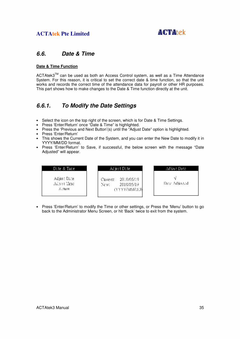
6.6.1. To Modify the Date Settings
• Select the icon on the top right of the screen, which is for Date & Time Settings. • Press ‘Enter/Return’ once “Date & Time” is highlighted. • Press the ‘Previous and Next Button’(s) until the “Adjust Date” option is highlighted. • Press ‘Enter/Return’ • This shows the Current Date of the System, and you can enter the New Date to modify it in
YYYY/MM/DD format. • Press ‘Enter/Return’ to Save, if successful, the below screen with the message “Date
Adjusted” will appear.
• Press ‘Enter/Return’ to modify the Time or other settings, or Press the ‘Menu’ button to go back to the Administrator Menu Screen, or hit ‘Back’ twice to exit from the system.
Date & TimeAdjus t DateAdjus t TimeRe tu rn Adjus t DateCurrent: 2010/05/19New: 2010/05/19(YYYY/MM/DD) Adjus t DateDate Adjus ted√
ACTAtek Pte Limited
ACTAtek3 Manual 36
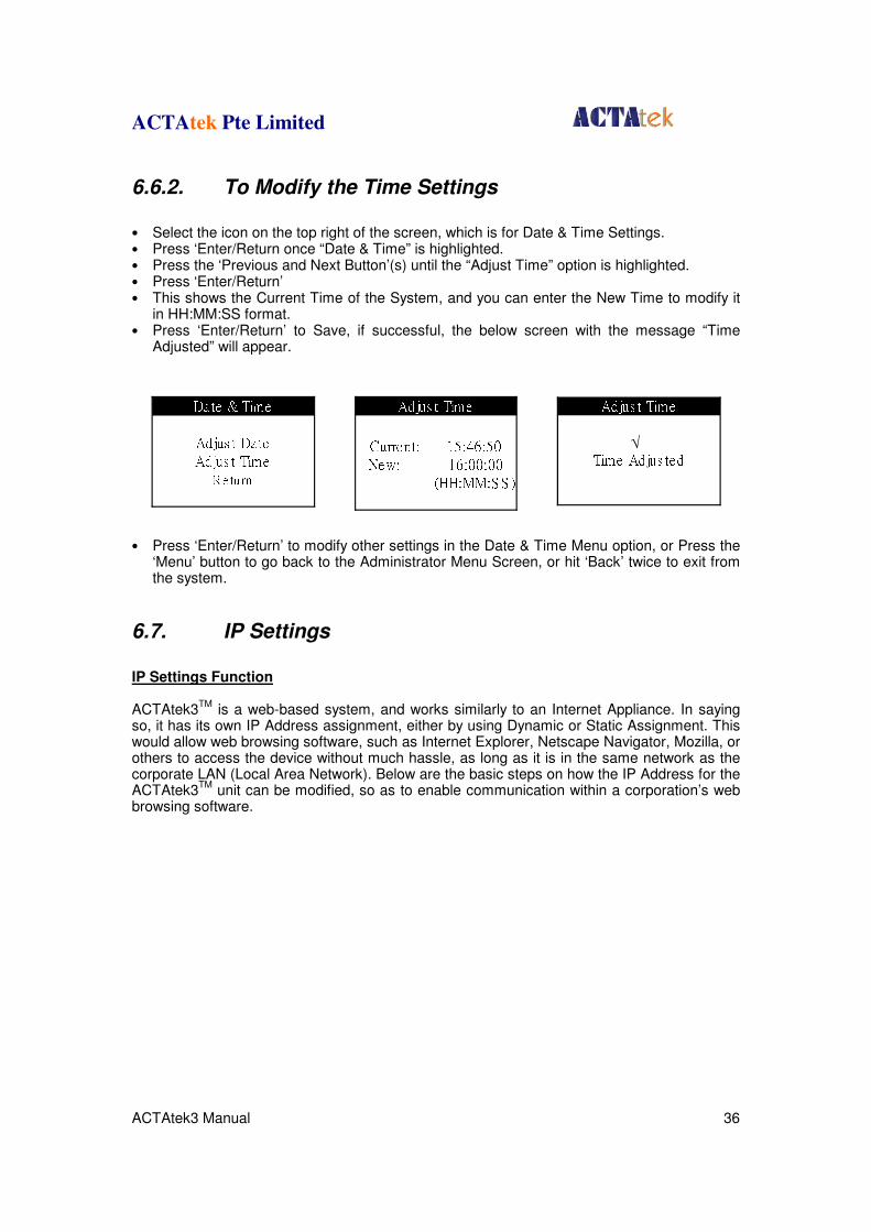
6.6.2. To Modify the Time Settings
• Select the icon on the top right of the screen, which is for Date & Time Settings. • Press ‘Enter/Return once “Date & Time” is highlighted. • Press the ‘Previous and Next Button’(s) until the “Adjust Time” option is highlighted. • Press ‘Enter/Return’ • This shows the Current Time of the System, and you can enter the New Time to modify it
in HH:MM:SS format. • Press ‘Enter/Return’ to Save, if successful, the below screen with the message “Time
Adjusted” will appear.
• Press ‘Enter/Return’ to modify other settings in the Date & Time Menu option, or Press the ‘Menu’ button to go back to the Administrator Menu Screen, or hit ‘Back’ twice to exit from the system.
6.7. IP Settings
IP Settings Function ACTAtek3
TM is a web-based system, and works similarly to an Internet Appliance. In saying
so, it has its own IP Address assignment, either by using Dynamic or Static Assignment. This would allow web browsing software, such as Internet Explorer, Netscape Navigator, Mozilla, or others to access the device without much hassle, as long as it is in the same network as the corporate LAN (Local Area Network). Below are the basic steps on how the IP Address for the ACTAtek3
TM unit can be modified, so as to enable communication within a corporation’s web
browsing software.
Date & TimeAdjus t DateAdjus t TimeRe tu rn Adjus t TimeCurrent: 15:46:50New: 16:00:00(HH:MM:S S ) Adjus t TimeTime Adjus ted√
ACTAtek Pte Limited
ACTAtek3 Manual 37
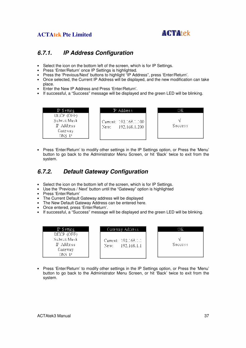
6.7.1. IP Address Configuration
• Select the icon on the bottom left of the screen, which is for IP Settings. • Press ‘Enter/Return’ once IP Settings is highlighted. • Press the ‘Previous/Next’ buttons to highlight “IP Address”, press ‘Enter/Return’. • Once selected, the Current IP Address will be displayed, and the new modification can take
place. • Enter the New IP Address and Press ‘Enter/Return’. • If successful, a “Success” message will be displayed and the green LED will be blinking.
• Press ‘Enter/Return’ to modify other settings in the IP Settings option, or Press the ‘Menu’ button to go back to the Administrator Menu Screen, or hit ‘Back’ twice to exit from the system.
6.7.2. Default Gateway Configuration
• Select the icon on the bottom left of the screen, which is for IP Settings. • Use the ‘Previous / Next’ button until the “Gateway” option is highlighted • Press ‘Enter/Return’ • The Current Default Gateway address will be displayed • The New Default Gateway Address can be entered here. • Once entered, press ‘Enter/Return’. • If successful, a “Success” message will be displayed and the green LED will be blinking.
• Press ‘Enter/Return’ to modify other settings in the IP Settings option, or Press the ‘Menu’ button to go back to the Administrator Menu Screen, or hit ‘Back’ twice to exit from the system.
IP Addres sCurrent: 192.168.1.100New: 192.168.1.200
Gateway Addres sCurrent: 192.168.1.1New: 192.168.1.1
IP S e ttingDHCP (OFF)S ubnet Mas kIP Addres sGatewayDNS IP
IP S e ttingDHCP (OFF)S ubnet Mas kIP Addres sGatewayDNS IP
OKS ucces s√
OKS ucces s√
ACTAtek Pte Limited
ACTAtek3 Manual 38
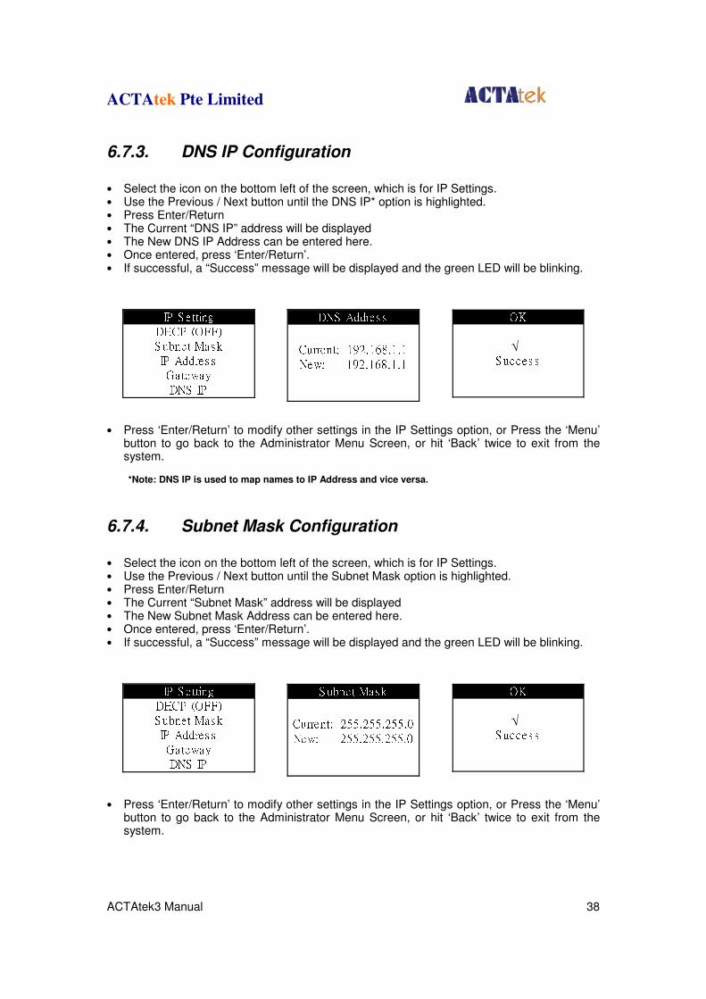
6.7.3. DNS IP Configuration
• Select the icon on the bottom left of the screen, which is for IP Settings. • Use the Previous / Next button until the DNS IP* option is highlighted. • Press Enter/Return • The Current “DNS IP” address will be displayed • The New DNS IP Address can be entered here. • Once entered, press ‘Enter/Return’. • If successful, a “Success” message will be displayed and the green LED will be blinking.
• Press ‘Enter/Return’ to modify other settings in the IP Settings option, or Press the ‘Menu’ button to go back to the Administrator Menu Screen, or hit ‘Back’ twice to exit from the system. *Note: DNS IP is used to map names to IP Address and vice versa.
6.7.4. Subnet Mask Configuration
• Select the icon on the bottom left of the screen, which is for IP Settings. • Use the Previous / Next button until the Subnet Mask option is highlighted. • Press Enter/Return • The Current “Subnet Mask” address will be displayed • The New Subnet Mask Address can be entered here. • Once entered, press ‘Enter/Return’. • If successful, a “Success” message will be displayed and the green LED will be blinking.
• Press ‘Enter/Return’ to modify other settings in the IP Settings option, or Press the ‘Menu’ button to go back to the Administrator Menu Screen, or hit ‘Back’ twice to exit from the system.
DNS Addres sCurrent: 192.168.1.1New: 192.168.1.1
S ubnet Mas kCurrent: 255.255.255.0New: 255.255.255.0
IP S e ttingDHCP (OFF)S ubnet Mas kIP Addres sGatewayDNS IP
IP S e ttingDHCP (OFF)S ubnet Mas kIP Addres sGatewayDNS IP
OKS ucces s√
OKS ucces s√
ACTAtek Pte Limited
ACTAtek3 Manual 39
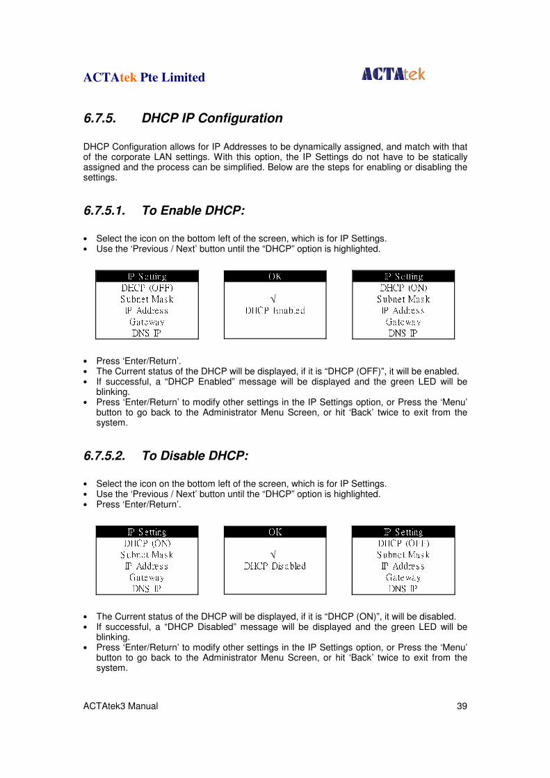
6.7.5. DHCP IP Configuration
DHCP Configuration allows for IP Addresses to be dynamically assigned, and match with that of the corporate LAN settings. With this option, the IP Settings do not have to be statically assigned and the process can be simplified. Below are the steps for enabling or disabling the settings.
6.7.5.1. To Enable DHCP:
• Select the icon on the bottom left of the screen, which is for IP Settings. • Use the ‘Previous / Next’ button until the “DHCP” option is highlighted.
• Press ‘Enter/Return’. • The Current status of the DHCP will be displayed, if it is “DHCP (OFF)”, it will be enabled. • If successful, a “DHCP Enabled” message will be displayed and the green LED will be
blinking. • Press ‘Enter/Return’ to modify other settings in the IP Settings option, or Press the ‘Menu’
button to go back to the Administrator Menu Screen, or hit ‘Back’ twice to exit from the system.
6.7.5.2. To Disable DHCP:
• Select the icon on the bottom left of the screen, which is for IP Settings. • Use the ‘Previous / Next’ button until the “DHCP” option is highlighted. • Press ‘Enter/Return’.
• The Current status of the DHCP will be displayed, if it is “DHCP (ON)”, it will be disabled. • If successful, a “DHCP Disabled” message will be displayed and the green LED will be
blinking. • Press ‘Enter/Return’ to modify other settings in the IP Settings option, or Press the ‘Menu’
button to go back to the Administrator Menu Screen, or hit ‘Back’ twice to exit from the system.
IP S e ttingDHCP (OFF)S ubnet Mas kIP Addres sGatewayDNS IP
IP S e ttingDHCP (OFF)S ubnet Mas kIP Addres sGatewayDNS IP
IP S e ttingDHCP (ON)S ubnet Mas kIP Addres sGatewayDNS IP
IP S e ttingDHCP (ON)S ubnet Mas kIP Addres sGatewayDNS IP
OKDHCP Enabled√
OKDHCP Dis abled√
ACTAtek Pte Limited
ACTAtek3 Manual 40
6.8. Terminal Settings
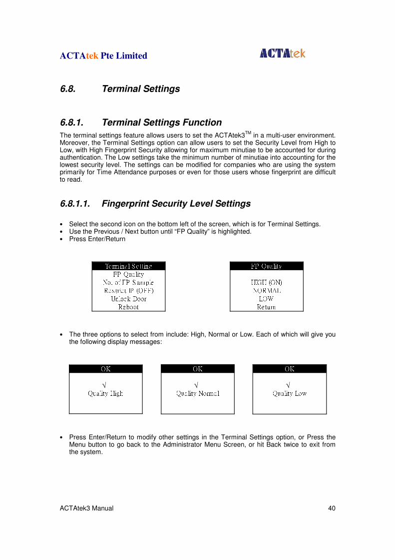
6.8.1. Terminal Settings Function
The terminal settings feature allows users to set the ACTAtek3TM
in a multi-user environment. Moreover, the Terminal Settings option can allow users to set the Security Level from High to Low, with High Fingerprint Security allowing for maximum minutiae to be accounted for during authentication. The Low settings take the minimum number of minutiae into accounting for the lowest security level. The settings can be modified for companies who are using the system primarily for Time Attendance purposes or even for those users whose fingerprint are difficult to read.
6.8.1.1. Fingerprint Security Level Settings
• Select the second icon on the bottom left of the screen, which is for Terminal Settings. • Use the Previous / Next button until “FP Quality” is highlighted. • Press Enter/Return
• The three options to select from include: High, Normal or Low. Each of which will give you
the following display messages:
• Press Enter/Return to modify other settings in the Terminal Settings option, or Press the
Menu button to go back to the Administrator Menu Screen, or hit Back twice to exit from the system.
FP QualityHIGH (ON)NORMALLOWReturnTermina l S e ttingFP QualityNo. of FP S ampleRes tric t IP (OFF)Unlock DoorReboot
OKQuality High√
OKQuality Normal√
OKQuality Low√
ACTAtek Pte Limited
ACTAtek3 Manual 41
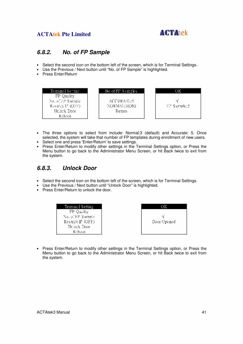
6.8.2. No. of FP Sample
• Select the second icon on the bottom left of the screen, which is for Terminal Settings. • Use the Previous / Next button until “No. of FP Sample” is highlighted. • Press Enter/Return
• The three options to select from include: Normal:3 (default) and Accurate: 5. Once
selected, the system will take that number of FP templates during enrollment of new users. • Select one and press 'Enter/Return' to save settings. • Press Enter/Return to modify other settings in the Terminal Settings option, or Press the
Menu button to go back to the Administrator Menu Screen, or hit Back twice to exit from the system.
6.8.3. Unlock Door
• Select the second icon on the bottom left of the screen, which is for Terminal Settings. • Use the Previous / Next button until “Unlock Door” is highlighted. • Press Enter/Return to unlock the door.
• Press Enter/Return to modify other settings in the Terminal Settings option, or Press the
Menu button to go back to the Administrator Menu Screen, or hit Back twice to exit from the system.
Terminal S e ttingFP QualityNo. of FP S ampleRes tric t IP (OFF)Unlock DoorRebootNo of FP S amplesACCURATE:5NORMAL:3(ON)Return OKFP S ample :3√
Termina l S e ttingFP QualityNo. of FP S ampleRes tric t IP (OFF)Unlock DoorRebootOKDoor Opened√
ACTAtek Pte Limited
ACTAtek3 Manual 42
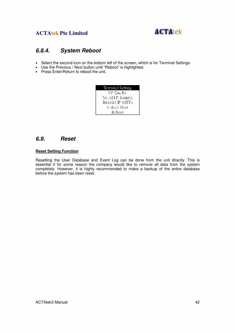
6.8.4. System Reboot
• Select the second icon on the bottom left of the screen, which is for Terminal Settings. • Use the Previous / Next button until “Reboot” is highlighted. • Press Enter/Return to reboot the unit.
6.9. Reset
Reset Setting Function Resetting the User Database and Event Log can be done from the unit directly. This is essential if for some reason the company would like to remove all data from the system completely. However, it is highly recommended to make a backup of the entire database before the system has been reset.
Terminal S e ttingFP QualityNo. of FP S ampleRes tric t IP (OFF)Unlock DoorReboot
ACTAtek Pte Limited
ACTAtek3 Manual 43
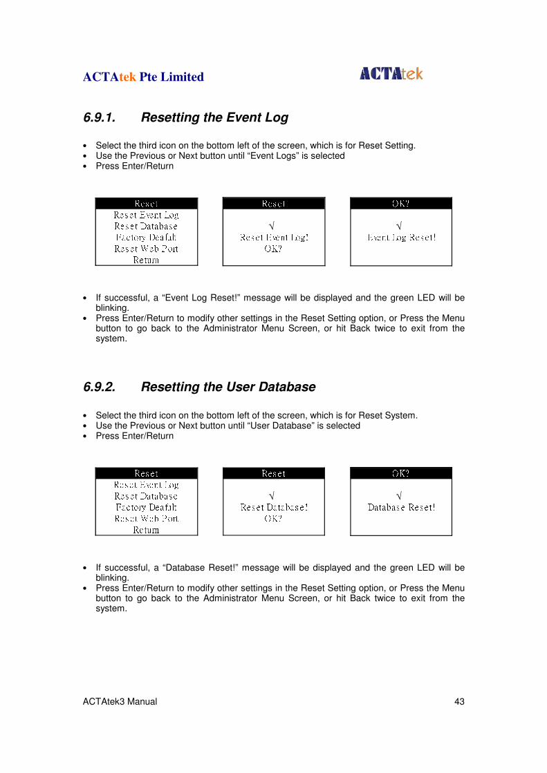
6.9.1. Resetting the Event Log
• Select the third icon on the bottom left of the screen, which is for Reset Setting. • Use the Previous or Next button until “Event Logs” is selected • Press Enter/Return
• If successful, a “Event Log Reset!” message will be displayed and the green LED will be
blinking. • Press Enter/Return to modify other settings in the Reset Setting option, or Press the Menu
button to go back to the Administrator Menu Screen, or hit Back twice to exit from the system.
6.9.2. Resetting the User Database
• Select the third icon on the bottom left of the screen, which is for Reset System. • Use the Previous or Next button until “User Database” is selected • Press Enter/Return
• If successful, a “Database Reset!” message will be displayed and the green LED will be
blinking. • Press Enter/Return to modify other settings in the Reset Setting option, or Press the Menu
button to go back to the Administrator Menu Screen, or hit Back twice to exit from the system.
Res e tRes et Event LogRes e t Databas eFactory DeafultRes e t Web P ortReturnRes e tRes e t Event Log!OK?√
OK?Event Log Res e t!√
Res e tRes et Event LogRes e t Databas eFactory DeafultRes e t Web P ortReturnRes e tRes et Databas e!OK?√
OK?Databas e Res e t!√

ACTAtek Pte Limited
ACTAtek3 Manual 44
6.9.3. Factory Default
• Select the third icon on the bottom left of the screen, which is for Reset System. • Use the Previous or Next button until “Factory Default” is selected. • Press Enter/Return • A message “System Reset!” will be displayed once the system has been successfully
resetn and rebooting.
6.9.4. Web Port
• Select the third icon on the bottom left of the screen, which is for Reset System. • Use the Previous or Next button until “Reset Web Port” is selected. • Press Enter/Return • A message “Web Port Reset!” will be displayed once the system has been successfully
reset.
6.10. Exit
Exit Function Once all your settings have been completed, you can either exit the system using the Back button on the keypad or by using the Exit option in the Administration Menu. • Select the icon on the bottom right of the screen, which is to Exit from the Admin Menu. • Press Enter/Return, and the Standby Mode will be displayed.
Res e tRes et Event LogRes e t Databas eFactory DeafultRes e t Web P ortReturn
Res e tRes et Event LogRes e t Databas eFactory DeafultRes e t Web P ortReturn
OK?S ys tem Res e t!√
Res e tRes et Web P ort!OK?√
OK?Web P ort Res et!√
Res e tFac tory Default!OK?√
ACTAtek Pte Limited
ACTAtek3 Manual 45
Chapter 7. Web Administration
Chapter 7. Web Administration Introduction ACTAtek3
TM works based on the TCP/IP networking protocol and web server technology,
which allows for remote administration via any standard web browser, e.g. Internet Explorer or Netscape Navigator. We have used Internet Explorer as our demonstrative guide; it works the same way with Netscape or any standard web browser. For queries regarding this, contact us at [email protected]. ACTAtek3
TM permits for 4 access levels:
• Personal User • User Administrator • Network Administrator • Super Administrator Personal User
The personal user login only allows for users to check their attendance records, and view their reports. No changes or modification is admissible through this configuration option. This is for employees who wish to check their attendance records or other reports generated by the system.
User Administrator
The user administrator access level lists a different set of configuration changes that can be made. More so, to pertain to HR or Payroll requirements. The changes can be made to Access levels of different departments, addition and monitoring of job functions, reporting, as well as, managing the employee list. Addition / deletion of employees can be done here, restricting access to rooms for different employees can also be done by the user administrator. Network Administrator
The network administrator is in charge of system configurations, such as, networking settings, terminal settings, clock setups, or password setups. Everything that involves technical knowing will be done by the network administrator. This role is usually assigned to a tech-savvy person, who is capable of making appropriate configuration changes and has basic knowledge of networking setup and IT-related issues. Super Administrator
The super administrator login combines the functions of 1 - 3, so the administrator is in charge of the whole system, including technical and administration functionalities. This guide is focusing on the Super Administrator usage which essentially cover all the functions.
Diagram 1a
ACTAtek Pte Limited
ACTAtek3 Manual 46
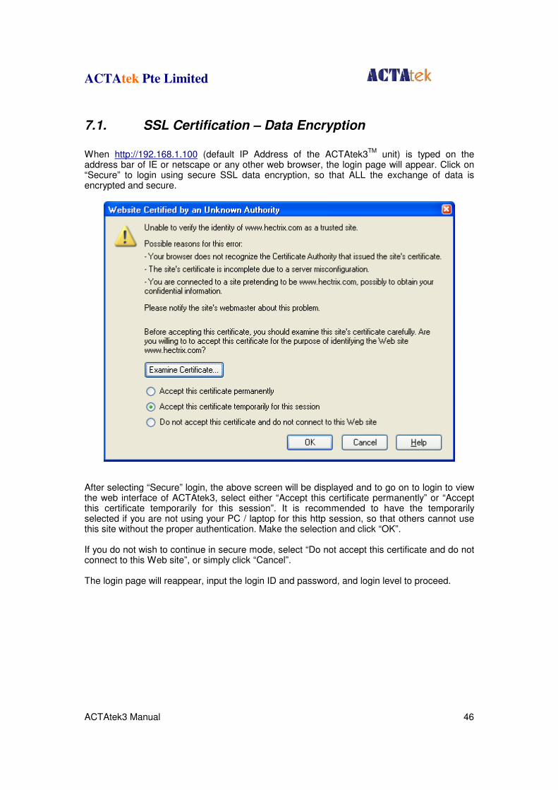
7.1. SSL Certification – Data Encryption
When http://192.168.1.100 (default IP Address of the ACTAtek3
TM unit) is typed on the
address bar of IE or netscape or any other web browser, the login page will appear. Click on “Secure” to login using secure SSL data encryption, so that ALL the exchange of data is encrypted and secure.
After selecting “Secure” login, the above screen will be displayed and to go on to login to view the web interface of ACTAtek3, select either “Accept this certificate permanently” or “Accept this certificate temporarily for this session”. It is recommended to have the temporarily selected if you are not using your PC / laptop for this http session, so that others cannot use this site without the proper authentication. Make the selection and click “OK”. If you do not wish to continue in secure mode, select “Do not accept this certificate and do not connect to this Web site”, or simply click “Cancel”. The login page will reappear, input the login ID and password, and login level to proceed.
ACTAtek Pte Limited
ACTAtek3 Manual 47
7.2. Terminal Status
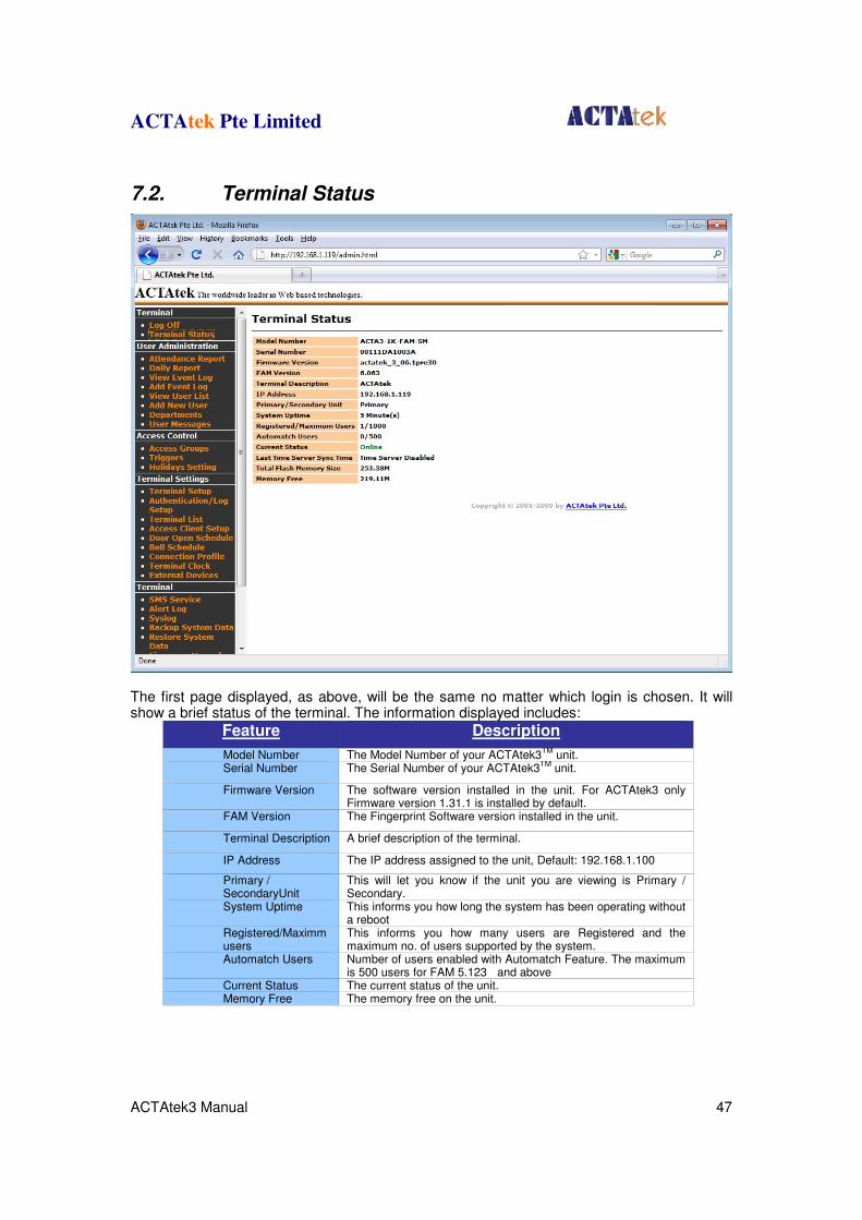
The first page displayed, as above, will be the same no matter which login is chosen. It will show a brief status of the terminal. The information displayed includes:
Feature Description
Model Number The Model Number of your ACTAtek3TM
unit. Serial Number The Serial Number of your ACTAtek3
TM unit.
Firmware Version The software version installed in the unit. For ACTAtek3 only Firmware version 1.31.1 is installed by default.
FAM Version The Fingerprint Software version installed in the unit.
Terminal Description A brief description of the terminal.
IP Address The IP address assigned to the unit, Default: 192.168.1.100
Primary / SecondaryUnit
This will let you know if the unit you are viewing is Primary / Secondary.
System Uptime This informs you how long the system has been operating without a reboot
Registered/Maximm users
This informs you how many users are Registered and the maximum no. of users supported by the system.
Automatch Users Number of users enabled with Automatch Feature. The maximum is 500 users for FAM 5.123 and above
Current Status The current status of the unit. Memory Free The memory free on the unit.
ACTAtek Pte Limited
ACTAtek3 Manual 48
Chapter 8. Super Administration Guide
Chapter 8. Super Administration Guide
8.1. Overview
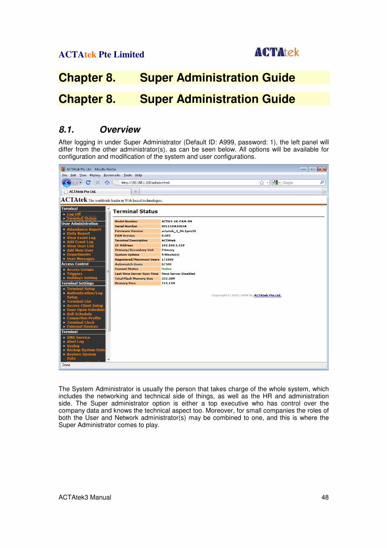
After logging in under Super Administrator (Default ID: A999, password: 1), the left panel will differ from the other administrator(s), as can be seen below. All options will be available for configuration and modification of the system and user configurations.
The System Administrator is usually the person that takes charge of the whole system, which includes the networking and technical side of things, as well as the HR and administration side. The Super administrator option is either a top executive who has control over the company data and knows the technical aspect too. Moreover, for small companies the roles of both the User and Network administrator(s) may be combined to one, and this is where the Super Administrator comes to play.
ACTAtek Pte Limited
ACTAtek3 Manual 49
From the left panel, the user administrator will be able to choose from the following:
8.1.1. Terminal
1. Log off - To log off from the system
2. Terminal Status - To view the overall terminal status
8.1.2. User Administration
1. Attendance Report - To view the attendance report of users in the sys tem
2. Daily Report - To view the daily report of users in the system
3. View Event Log - To view the event log of the users in the system
4. Add Event Log - To add an event log in to the system
5. View User List - To view the list of users in the system
6. Add New User - To add a new user into the system
7. Departments - To view the list of departments or add a new de partment
8. User Messages - To send personalized messages to individual users during clock IN/OUT
8.1.3. Access Control
1. Access Groups - To view or modify existing access groups or add a new group
2. Triggers - To view or modify the trigger list.
3. Holidays - To setup the systems for recognizing holidays for unique settings.
8.1.4. Terminal Settings
1. Terminal Setup - To view modify the terminal settings, e.g. IP / Gateway.
2. Primary / Secondary Setup - To setup the units in primary / secondary mode.
3. Terminal List - To view the list of terminals connected.
4. Door Open Schedule - To view or modify the door opening schedule.
5. Bell Schedule - To view or modify the bell schedule period.
6. Connection Profile - Use for manual Agent configuration.
7. Terminal Clock - To view or modify the terminal clock settings.
8. External Devices - To connect external devices to the ACTAtek3 unit.

ACTAtek Pte Limited
ACTAtek3 Manual 50
8.1.5. Tools
1. Backup System Data - To backup the system data.
2. Restore System Data - To restore the system data from a previous set ting.
3. Firmware Upgrade - To upgrade the firmware provided by Hectrix Ltd.
4. Download Report - To download access log report in Excel or Txt for mats.
5. Capture Fingerprint - To capture fingerprint images(for review purpose).
6. Remote Door Open - To open the door using the web interface.
7. Reboot - To reboot the unit remotely.
The above is a brief overview of what the features on the left panel are for, in the next session, you will be able to understand in more detail what each function does, and how to set up your ACTAtek3
TM and manage the system settings.
ACTAtek Pte Limited
ACTAtek3 Manual 51
8.2. User Administration
8.2.1. Attendance Report
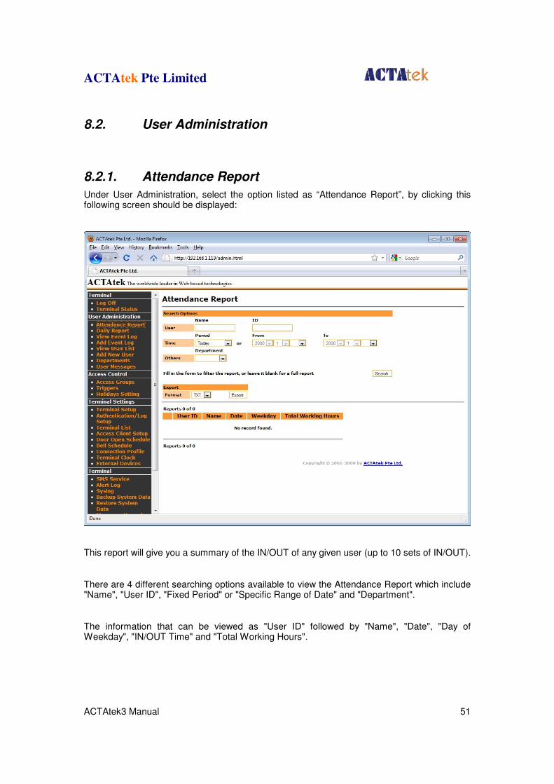
Under User Administration, select the option listed as “Attendance Report”, by clicking this following screen should be displayed:
This report will give you a summary of the IN/OUT of any given user (up to 10 sets of IN/OUT).
There are 4 different searching options available to view the Attendance Report which include "Name", "User ID", "Fixed Period" or "Specific Range of Date" and "Department".
The information that can be viewed as "User ID" followed by "Name", "Date", "Day of Weekday", "IN/OUT Time" and "Total Working Hours".

ACTAtek Pte Limited
ACTAtek3 Manual 52
You get an overview of the Total Hours worked by any given employee on any day, provided the event logs haven't been deleted. This information can then be exported to Excel or text files.
ACTAtek Pte Limited
ACTAtek3 Manual 53
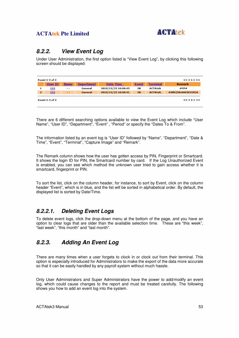
8.2.2. View Event Log
Under User Administration, the first option listed is “View Event Log”, by clicking this following screen should be displayed:
There are 6 different searching options available to view the Event Log which include “User Name”, “User ID”, “Department”, “Event” , “Period” or specify the “Dates To & From”.
The information listed by an event log is “User ID” followed by “Name”, “Department”, “Date & Time”, “Event”, “Terminal”, “Capture Image” and “Remark”.
The Remark column shows how the user has gotten access by PIN, Fingerprint or Smartcard. It shows the login ID for PIN, the Smartcard number by card. If the Log Unauthorized Event is enabled, you can see which method the unknown user tried to gain access whether it is smartcard, fingerprint or PIN.
To sort the list, click on the column header, for instance, to sort by Event, click on the column header “Event”, which is in blue, and the list will be sorted in alphabetical order. By default, the displayed list is sorted by Date/Time.
8.2.2.1. Deleting Event Logs
To delete event logs, click the drop-down menu at the bottom of the page, and you have an option to clear logs that are older than the available selection time. These are “this week”, “last week”, “this month” and “last month”.
8.2.3. Adding An Event Log
There are many times when a user forgets to clock in or clock out from their terminal. This option is especially introduced for Administrators to make the export of the data more accurate so that it can be easily handled by any payroll system without much hassle.
Only User Administrators and Super Administrators have the power to add/modify an event log, which could cause changes to the report and must be treated carefully. The following shows you how to add an event log into the system.
ACTAtek Pte Limited
ACTAtek3 Manual 54
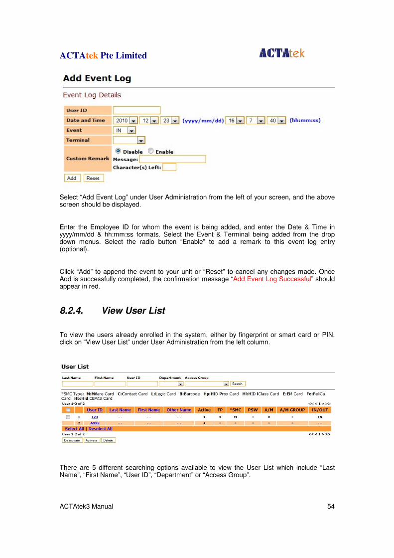
Select “Add Event Log” under User Administration from the left of your screen, and the above screen should be displayed.
Enter the Employee ID for whom the event is being added, and enter the Date & Time in yyyy/mm/dd & hh:mm:ss formats. Select the Event & Terminal being added from the drop down menus. Select the radio button “Enable” to add a remark to this event log entry (optional).
Click “Add” to append the event to your unit or “Reset” to cancel any changes made. Once Add is successfully completed, the confirmation message “Add Event Log Successful” should appear in red.
8.2.4. View User List
To view the users already enrolled in the system, either by fingerprint or smart card or PIN, click on “View User List” under User Administration from the left column.
There are 5 different searching options available to view the User List which include “Last Name”, “First Name”, “User ID”, “Department” or “Access Group”.
ACTAtek Pte Limited
ACTAtek3 Manual 55
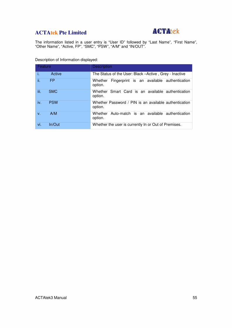
The information listed in a user entry is “User ID” followed by “Last Name”, “First Name”, “Other Name”, “Active, FP”, “SMC”, “PSW”, “A/M” and “IN/OUT”.
Description of Information displayed:
Feature Description
i. Active The Status of the User: Black –Active , Grey - Inactive
ii. FP Whether Fingerprint is an available authentication option.
iii. SMC Whether Smart Card is an available authentication option.
iv. PSW Whether Password / PIN is an available authentication option.
v. A/M Whether Auto-match is an available authentication option.
vi. In/Out Whether the user is currently In or Out of Premises.
ACTAtek Pte Limited
ACTAtek3 Manual 56
8.2.4.1. To sort:
To sort the list, click on the column header, for instance, to sort by Last Name, click on the column header “Last Name”, which is in blue, and the list will be sorted in alphabetical order. By default, the displayed list is sorted by ID.
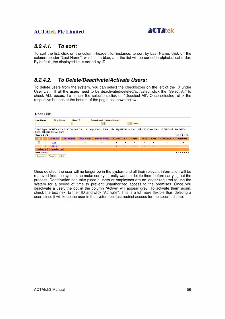
8.2.4.2. To Delete/Deactivate/Activate Users:
To delete users from the system, you can select the checkboxes on the left of the ID under User List. If all the users need to be deactivated/deleted/activated, click the “Select All” to check ALL boxes. To cancel the selection, click on “Deselect All”. Once selected, click the respective buttons at the bottom of the page, as shown below.
Once deleted, the user will no longer be in the system and all their relevant information will be removed from the system, so make sure you really want to delete them before carrying out the process. Deactivation can take place if users or employees are no longer required to use the system for a period of time to prevent unauthorized access to the premises. Once you deactivate a user, the dot in the column “Active” will appear grey. To activate them again, check the box next to their ID and click “Activate”. This is a lot more flexible than deleting a user, since it will keep the user in the system but just restrict access for the specified time.
ACTAtek Pte Limited
ACTAtek3 Manual 57
8.2.5. To Add New Users
There are 2 ways of adding users to the system; you can either add them directly at the web interface, or at the terminal. We have already discussed how to add a user at the terminal (in Section 5.2), now let us look at how to add a user directly from the web interface.
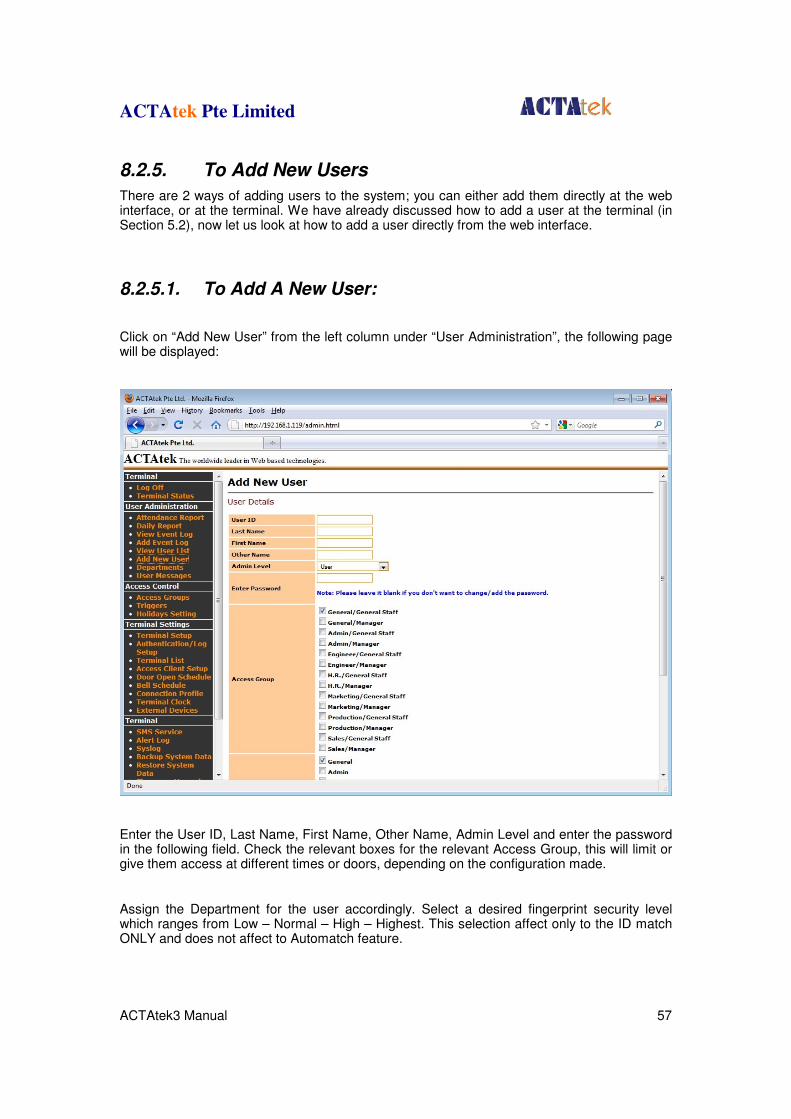
8.2.5.1. To Add A New User:
Click on “Add New User” from the left column under “User Administration”, the following page will be displayed:
Enter the User ID, Last Name, First Name, Other Name, Admin Level and enter the password in the following field. Check the relevant boxes for the relevant Access Group, this will limit or give them access at different times or doors, depending on the configuration made.
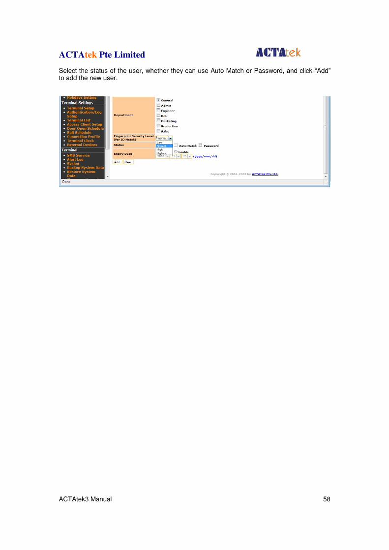
Assign the Department for the user accordingly. Select a desired fingerprint security level which ranges from Low – Normal – High – Highest. This selection affect only to the ID match ONLY and does not affect to Automatch feature.
ACTAtek Pte Limited
ACTAtek3 Manual 58
Select the status of the user, whether they can use Auto Match or Password, and click “Add” to add the new user.
ACTAtek Pte Limited
ACTAtek3 Manual 59
8.2.6. Departments
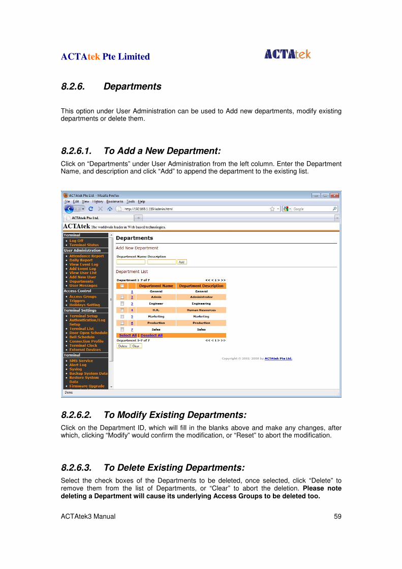
This option under User Administration can be used to Add new departments, modify existing departments or delete them.
8.2.6.1. To Add a New Department:
Click on “Departments” under User Administration from the left column. Enter the Department Name, and description and click “Add” to append the department to the existing list.
8.2.6.2. To Modify Existing Departments:
Click on the Department ID, which will fill in the blanks above and make any changes, after which, clicking “Modify” would confirm the modification, or “Reset” to abort the modification.
8.2.6.3. To Delete Existing Departments:
Select the check boxes of the Departments to be deleted, once selected, click “Delete” to remove them from the list of Departments, or “Clear” to abort the deletion. Please note deleting a Department will cause its underlying Access Groups to be deleted too.
ACTAtek Pte Limited
ACTAtek3 Manual 60
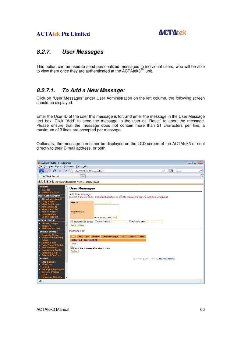
8.2.7. User Messages
This option can be used to send personalized messages to individual users, who will be able to view them once they are authenticated at the ACTAtek3
TM unit.
8.2.7.1. To Add a New Message:
Click on “User Messages” under User Administration on the left column, the following screen should be displayed.
Enter the User ID of the user this message is for, and enter the message in the User Message text box. Click “Add” to send the message to the user or “Reset” to abort the message. Please ensure that the message does not contain more than 21 characters per line, a maximum of 3 lines are accepted per message.
Optionally, the message can either be displayed on the LCD screen of the ACTAtek3 or sent directly to their E-mail address, or both.

ACTAtek Pte Limited
ACTAtek3 Manual 61
8.2.7.2. To Delete an existing User Message:
Check the box of the relevant message, and if all need to be checked, click “Select All”, and hit “Delete”. If the delete does not need to be made, click “Deselect All” to uncheck all boxes.
ACTAtek Pte Limited
ACTAtek3 Manual 62
8.3. Access Control
8.3.1. Access Groups
An Access Group allows for users to be given standard access for the workplace. Different departments may have different access rights and some corporations have employers who are on shift duties, and may need different access levels for each shift, depending upon their time of entry and exit from the workplace. To fasten the procedure of giving access rights, it can now be done for groups, instead of individuals to simplify the process and give it more transparency. This option can only be configured by the User Administrator or the Super Administrator.
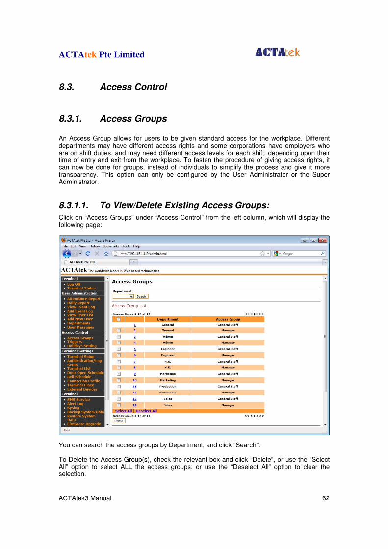
8.3.1.1. To View/Delete Existing Access Groups:
Click on “Access Groups” under “Access Control” from the left column, which will display the following page:
You can search the access groups by Department, and click “Search”. To Delete the Access Group(s), check the relevant box and click “Delete”, or use the “Select All” option to select ALL the access groups; or use the “Deselect All” option to clear the selection.
ACTAtek Pte Limited
ACTAtek3 Manual 63
8.3.1.2. To Add a New Access Group
Under “Add Access Group”, select the relevant Department from the drop down menu and input the name of the access group being added, and click “Add”.
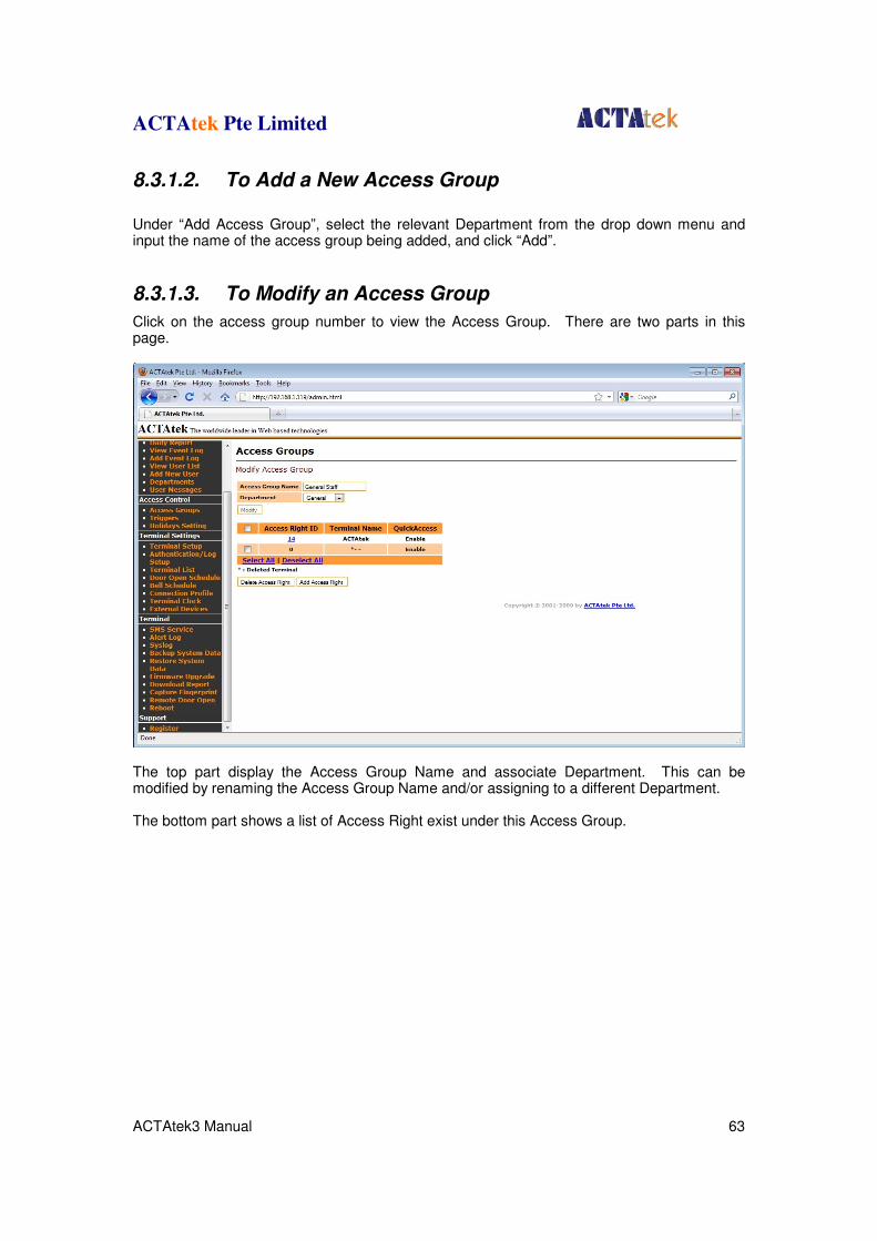
8.3.1.3. To Modify an Access Group
Click on the access group number to view the Access Group. There are two parts in this page.
The top part display the Access Group Name and associate Department. This can be modified by renaming the Access Group Name and/or assigning to a different Department. The bottom part shows a list of Access Right exist under this Access Group.
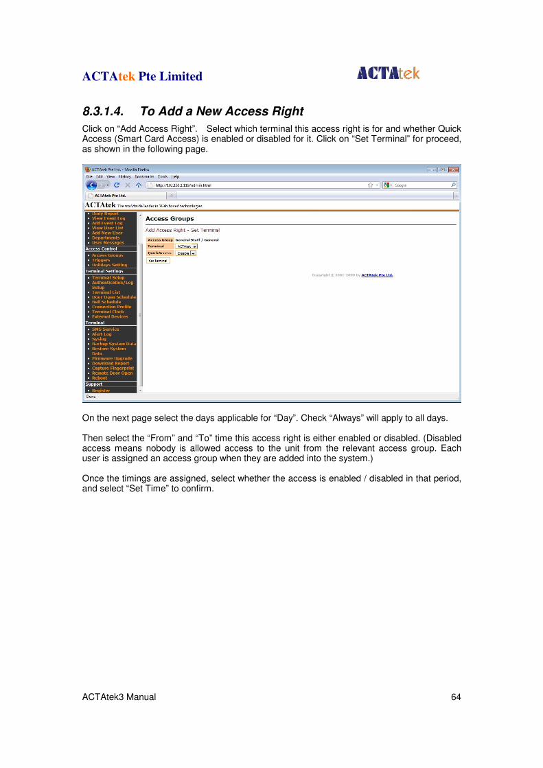
ACTAtek Pte Limited
ACTAtek3 Manual 64
8.3.1.4. To Add a New Access Right
Click on “Add Access Right”. Select which terminal this access right is for and whether Quick Access (Smart Card Access) is enabled or disabled for it. Click on “Set Terminal” for proceed, as shown in the following page.
On the next page select the days applicable for “Day”. Check “Always” will apply to all days. Then select the “From” and “To” time this access right is either enabled or disabled. (Disabled access means nobody is allowed access to the unit from the relevant access group. Each user is assigned an access group when they are added into the system.) Once the timings are assigned, select whether the access is enabled / disabled in that period, and select “Set Time” to confirm.
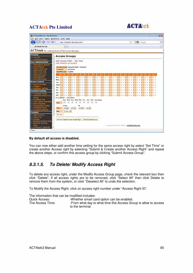
ACTAtek Pte Limited
ACTAtek3 Manual 65
By default all access is disabled. You can now either add another time setting for the same access right by select “Set Time” or create another Access right by selecting “Submit & Create another Access Right” and repeat the above steps, or confirm this access group by clicking “Submit Access Group”.
8.3.1.5. To Delete/ Modify Access Right
To delete any access right, under the Modify Access Group page, check the relevant box then click “Delete”. If all access rights are to be removed, click “Select All” then click Delete to remove them from the system, or click “Deselect All” to undo the selection. To Modify the Access Right, click on access right number under “Access Right ID”. The information that can be modified includes: Quick Access: -Whether smart card option can be enabled. The Access Time: -From what day to what time this Access Group is allow to access
to the terminal.
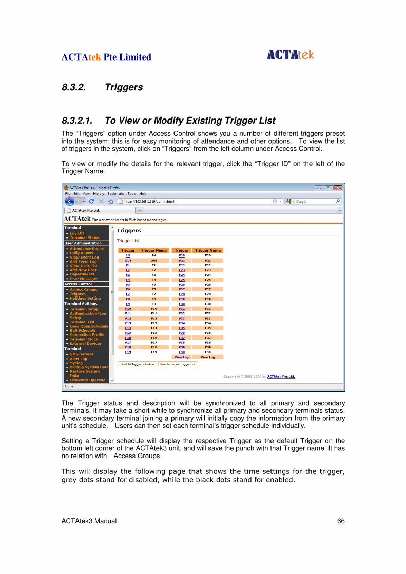
ACTAtek Pte Limited
ACTAtek3 Manual 66
8.3.2. Triggers
8.3.2.1. To View or Modify Existing Trigger List
The “Triggers” option under Access Control shows you a number of different triggers preset into the system; this is for easy monitoring of attendance and other options. To view the list of triggers in the system, click on “Triggers” from the left column under Access Control. To view or modify the details for the relevant trigger, click the “Trigger ID” on the left of the Trigger Name.
The Trigger status and description will be synchronized to all primary and secondary terminals. It may take a short while to synchronize all primary and secondary terminals status. A new secondary terminal joining a primary will initially copy the information from the primary unit's schedule. Users can then set each terminal's trigger schedule individually. Setting a Trigger schedule will display the respective Trigger as the default Trigger on the bottom left corner of the ACTAtek3 unit, and will save the punch with that Trigger name. It has no relation with Access Groups.
This will display the following page that shows the time settings for the trigger, grey dots stand for disabled, while the black dots stand for enabled.
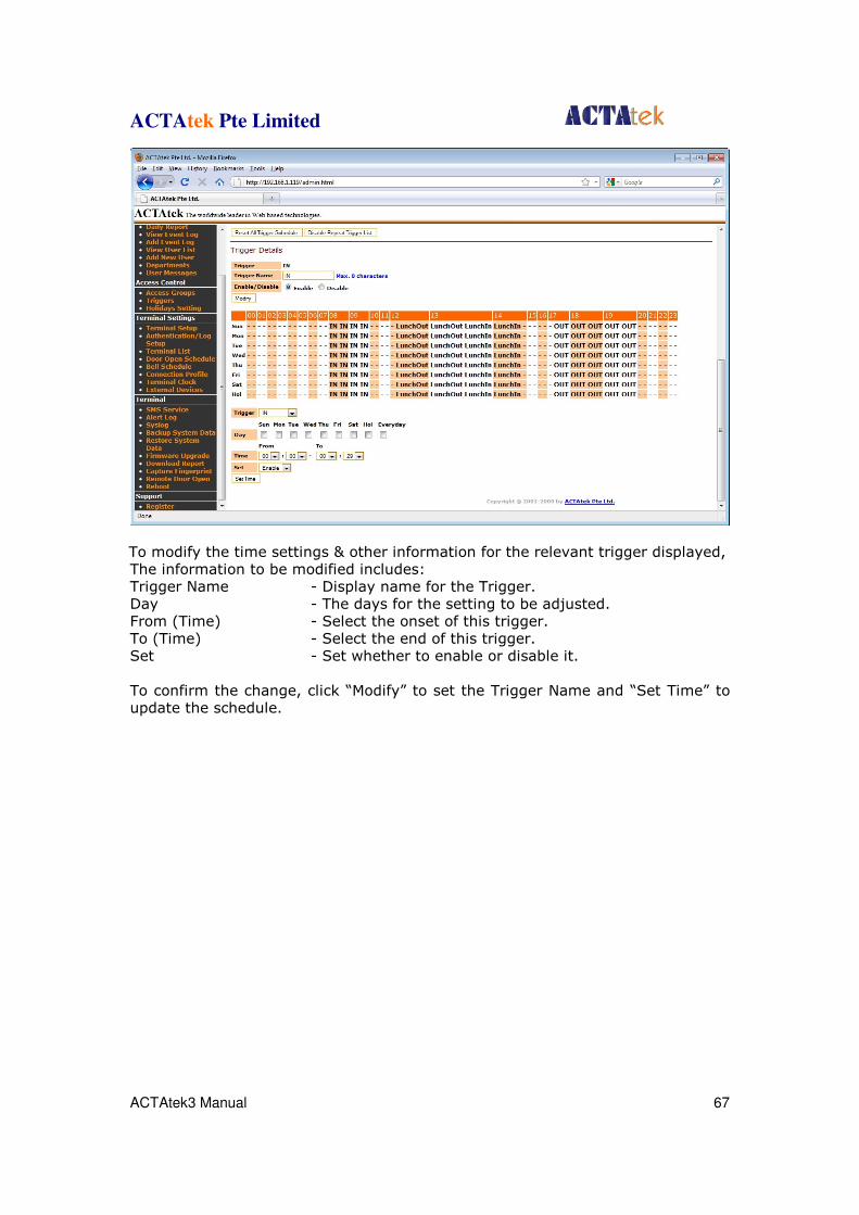
ACTAtek Pte Limited
ACTAtek3 Manual 67
To modify the time settings & other information for the relevant trigger displayed, The information to be modified includes: Trigger Name - Display name for the Trigger. Day - The days for the setting to be adjusted. From (Time) - Select the onset of this trigger. To (Time) - Select the end of this trigger. Set - Set whether to enable or disable it. To confirm the change, click “Modify” to set the Trigger Name and “Set Time” to update the schedule.
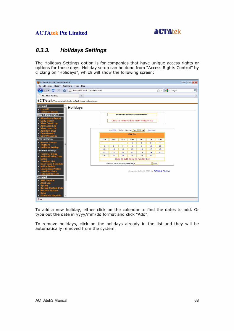
ACTAtek Pte Limited
ACTAtek3 Manual 68
8.3.3. Holidays Settings
The Holidays Settings option is for companies that have unique access rights or options for those days. Holiday setup can be done from “Access Rights Control” by clicking on “Holidays”, which will show the following screen:
To add a new holiday, either click on the calendar to find the dates to add. Or type out the date in yyyy/mm/dd format and click “Add”. To remove holidays, click on the holidays already in the list and they will be automatically removed from the system.
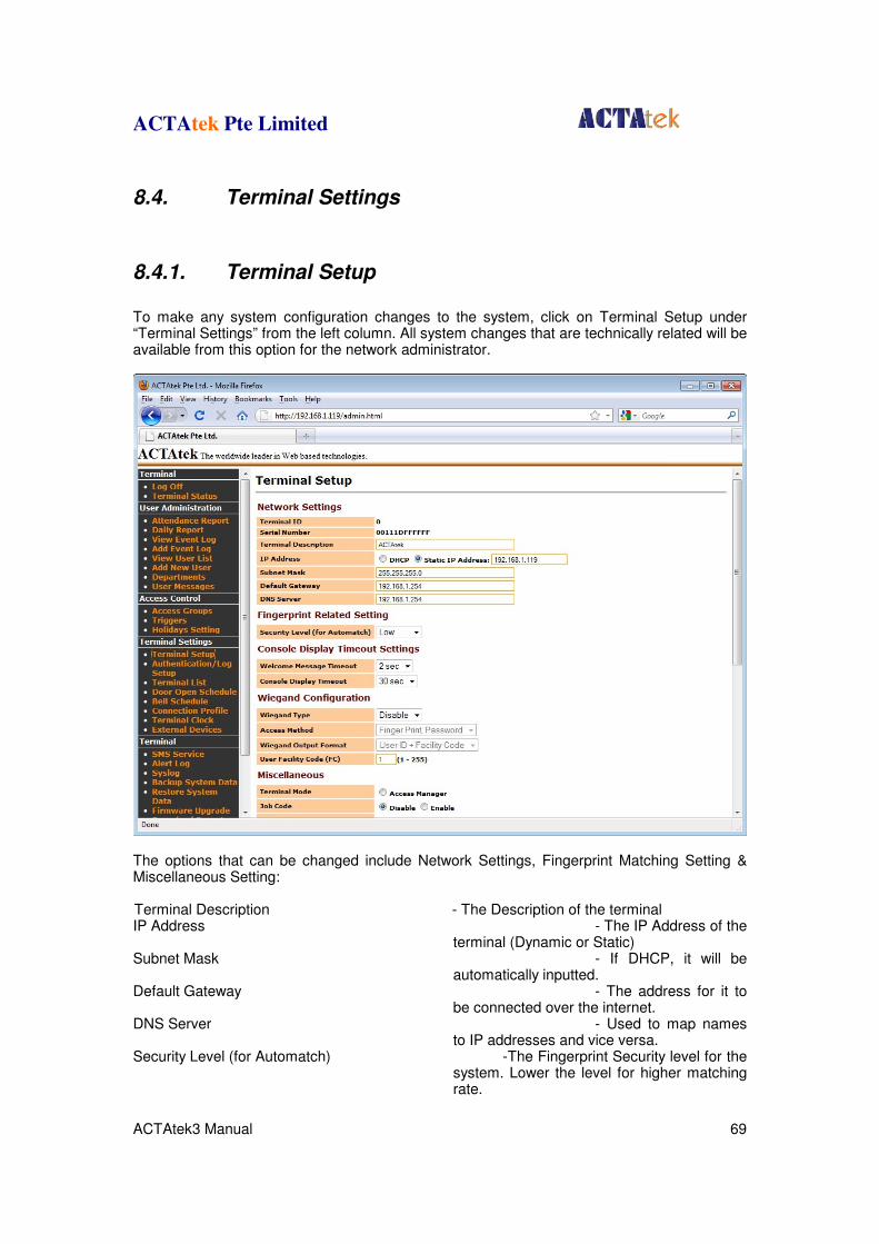
ACTAtek Pte Limited
ACTAtek3 Manual 69
8.4. Terminal Settings
8.4.1. Terminal Setup
To make any system configuration changes to the system, click on Terminal Setup under “Terminal Settings” from the left column. All system changes that are technically related will be available from this option for the network administrator.
The options that can be changed include Network Settings, Fingerprint Matching Setting & Miscellaneous Setting: Terminal Description - The Description of the terminal IP Address - The IP Address of the
terminal (Dynamic or Static) Subnet Mask - If DHCP, it will be
automatically inputted. Default Gateway - The address for it to
be connected over the internet. DNS Server - Used to map names
to IP addresses and vice versa. Security Level (for Automatch) -The Fingerprint Security level for the
system. Lower the level for higher matching rate.
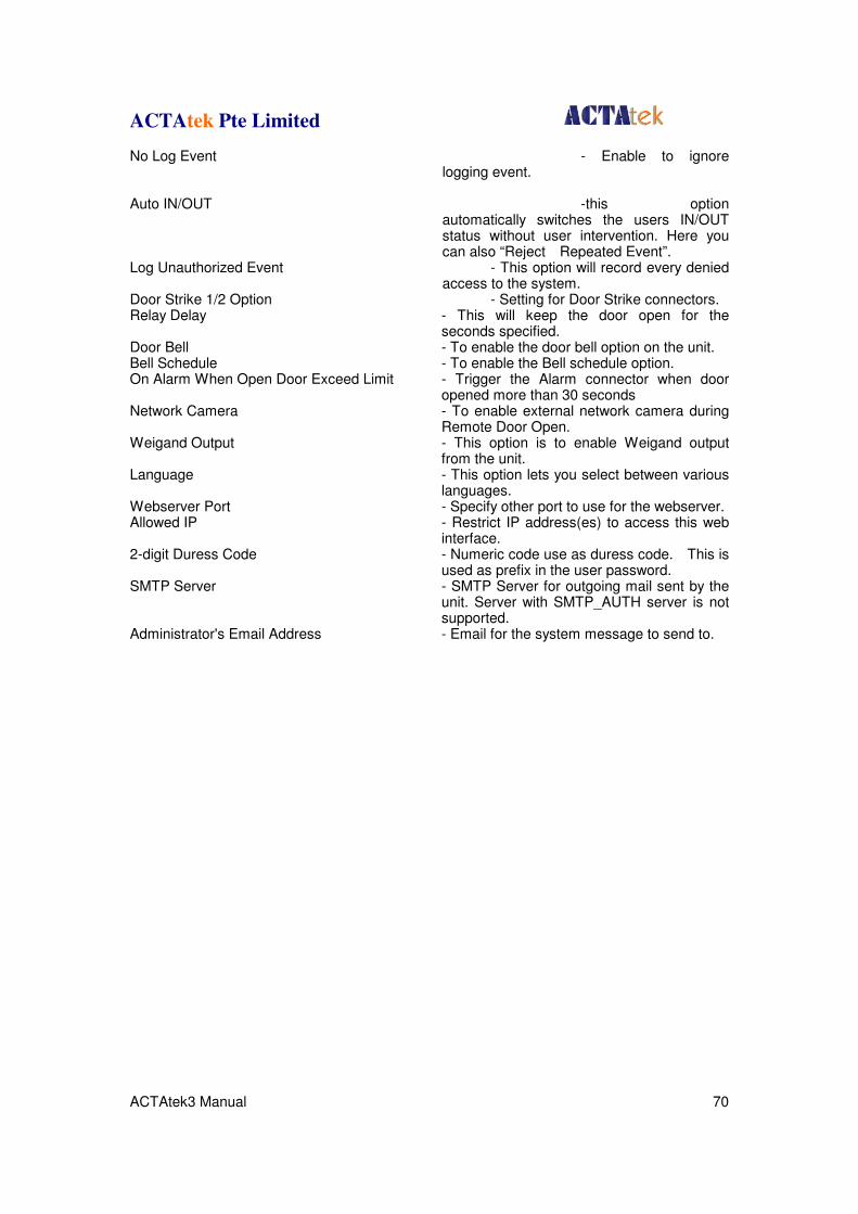
ACTAtek Pte Limited
ACTAtek3 Manual 70
No Log Event - Enable to ignore logging event.
Auto IN/OUT -this option
automatically switches the users IN/OUT status without user intervention. Here you can also “Reject Repeated Event”.
Log Unauthorized Event - This option will record every denied access to the system.
Door Strike 1/2 Option - Setting for Door Strike connectors. Relay Delay - This will keep the door open for the
seconds specified. Door Bell - To enable the door bell option on the unit. Bell Schedule - To enable the Bell schedule option. On Alarm When Open Door Exceed Limit - Trigger the Alarm connector when door
opened more than 30 seconds Network Camera - To enable external network camera during
Remote Door Open. Weigand Output - This option is to enable Weigand output
from the unit. Language - This option lets you select between various
languages. Webserver Port - Specify other port to use for the webserver. Allowed IP - Restrict IP address(es) to access this web
interface. 2-digit Duress Code - Numeric code use as duress code. This is
used as prefix in the user password. SMTP Server - SMTP Server for outgoing mail sent by the
unit. Server with SMTP_AUTH server is not supported.
Administrator's Email Address - Email for the system message to send to.
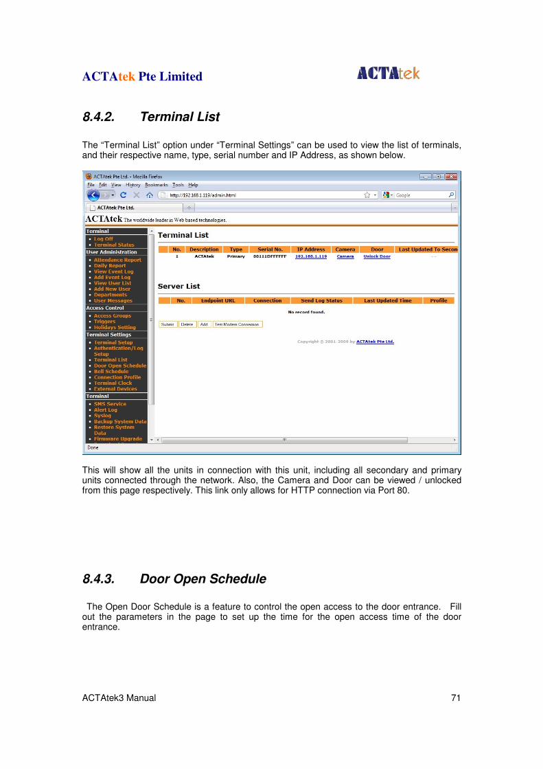
ACTAtek Pte Limited
ACTAtek3 Manual 71
8.4.2. Terminal List
The “Terminal List” option under “Terminal Settings” can be used to view the list of terminals, and their respective name, type, serial number and IP Address, as shown below.
This will show all the units in connection with this unit, including all secondary and primary units connected through the network. Also, the Camera and Door can be viewed / unlocked from this page respectively. This link only allows for HTTP connection via Port 80.
8.4.3. Door Open Schedule
The Open Door Schedule is a feature to control the open access to the door entrance. Fill out the parameters in the page to set up the time for the open access time of the door entrance.
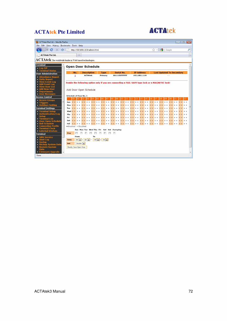
ACTAtek Pte Limited
ACTAtek3 Manual 72
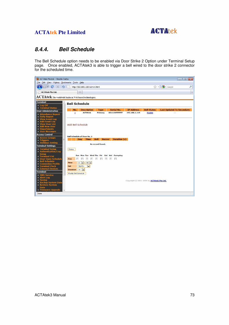
ACTAtek Pte Limited
ACTAtek3 Manual 73
8.4.4. Bell Schedule
The Bell Schedule option needs to be enabled via Door Strike 2 Option under Terminal Setup page. Once enabled, ACTAtek3 is able to trigger a bell wired to the door strike 2 connector for the scheduled time.
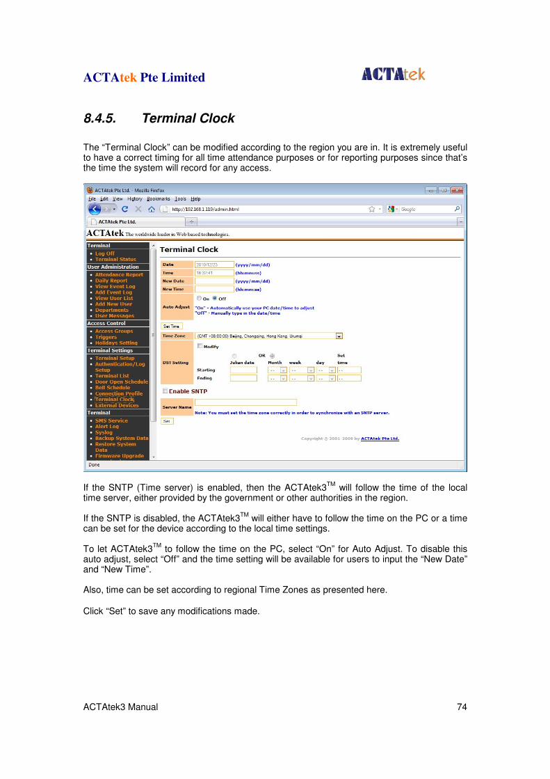
ACTAtek Pte Limited
ACTAtek3 Manual 74
8.4.5. Terminal Clock
The “Terminal Clock” can be modified according to the region you are in. It is extremely useful to have a correct timing for all time attendance purposes or for reporting purposes since that’s the time the system will record for any access.
If the SNTP (Time server) is enabled, then the ACTAtek3
TM will follow the time of the local
time server, either provided by the government or other authorities in the region. If the SNTP is disabled, the ACTAtek3
TM will either have to follow the time on the PC or a time
can be set for the device according to the local time settings. To let ACTAtek3
TM to follow the time on the PC, select “On” for Auto Adjust. To disable this
auto adjust, select “Off” and the time setting will be available for users to input the “New Date” and “New Time”. Also, time can be set according to regional Time Zones as presented here.
Click “Set” to save any modifications made.
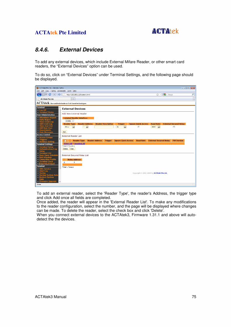
ACTAtek Pte Limited
ACTAtek3 Manual 75
8.4.6. External Devices
To add any external devices, which include External Mifare Reader, or other smart card readers, the “External Devices” option can be used. To do so, click on “External Devices” under Terminal Settings, and the following page should be displayed.
To add an external reader, select the 'Reader Type', the reader's Address, the trigger type and click Add once all fields are completed. Once added, the reader will appear in the 'External Reader List'. To make any modifications to the reader configuration, select the number, and the page will be displayed where changes can be made. To delete the reader, select the check box and click 'Delete'. When you connect external devices to the ACTAtek3, Firmware 1.31.1 and above will auto-detect the the devices.
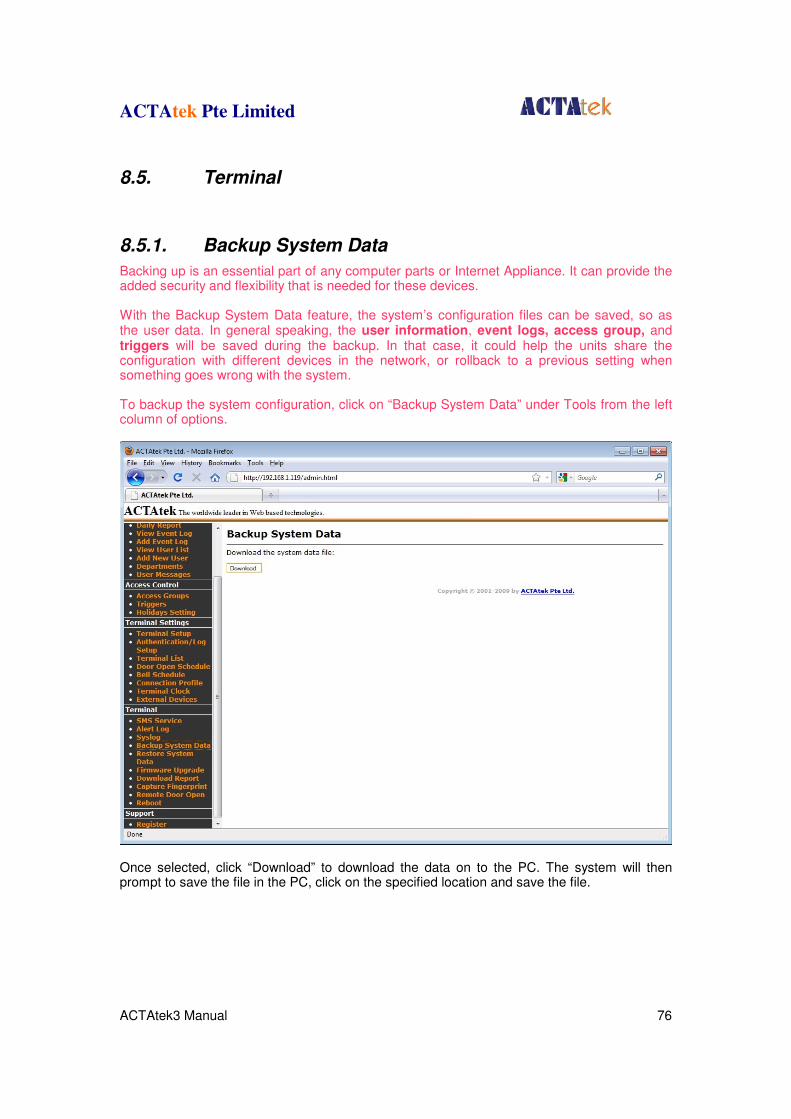
ACTAtek Pte Limited
ACTAtek3 Manual 76
8.5. Terminal
8.5.1. Backup System Data
Backing up is an essential part of any computer parts or Internet Appliance. It can provide the added security and flexibility that is needed for these devices. With the Backup System Data feature, the system’s configuration files can be saved, so as the user data. In general speaking, the user information, event logs, access group, and triggers will be saved during the backup. In that case, it could help the units share the configuration with different devices in the network, or rollback to a previous setting when something goes wrong with the system. To backup the system configuration, click on “Backup System Data” under Tools from the left column of options.
Once selected, click “Download” to download the data on to the PC. The system will then prompt to save the file in the PC, click on the specified location and save the file.
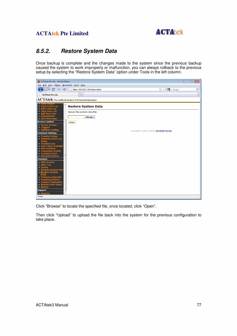
ACTAtek Pte Limited
ACTAtek3 Manual 77
8.5.2. Restore System Data
Once backup is complete and the changes made to the system since the previous backup caused the system to work improperly or malfunction, you can always rollback to the previous setup by selecting the “Restore System Data” option under Tools in the left column.
Click “Browse” to locate the specified file, once located, click “Open”. Then click “Upload” to upload the file back into the system for the previous configuration to take place.
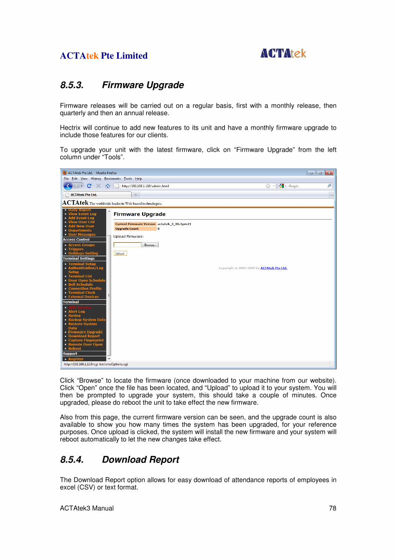
ACTAtek Pte Limited
ACTAtek3 Manual 78
8.5.3. Firmware Upgrade
Firmware releases will be carried out on a regular basis, first with a monthly release, then quarterly and then an annual release. Hectrix will continue to add new features to its unit and have a monthly firmware upgrade to include those features for our clients. To upgrade your unit with the latest firmware, click on “Firmware Upgrade” from the left column under “Tools”.
Click “Browse” to locate the firmware (once downloaded to your machine from our website). Click “Open” once the file has been located, and “Upload” to upload it to your system. You will then be prompted to upgrade your system, this should take a couple of minutes. Once upgraded, please do reboot the unit to take effect the new firmware. Also from this page, the current firmware version can be seen, and the upgrade count is also available to show you how many times the system has been upgraded, for your reference purposes. Once upload is clicked, the system will install the new firmware and your system will reboot automatically to let the new changes take effect.
8.5.4. Download Report
The Download Report option allows for easy download of attendance reports of employees in excel (CSV) or text format.
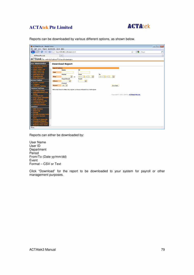
ACTAtek Pte Limited
ACTAtek3 Manual 79
Reports can be downloaded by various different options, as shown below.
Reports can either be downloaded by: User Name User ID Department Period From/To (Date yy/mm/dd) Event Format – CSV or Text Click “Download” for the report to be downloaded to your system for payroll or other management purposes.
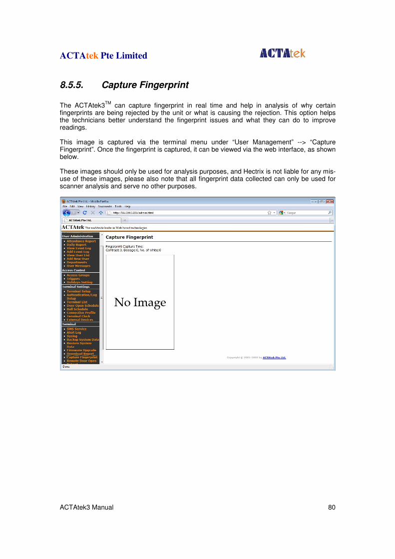
ACTAtek Pte Limited
ACTAtek3 Manual 80
8.5.5. Capture Fingerprint
The ACTAtek3
TM can capture fingerprint in real time and help in analysis of why certain
fingerprints are being rejected by the unit or what is causing the rejection. This option helps the technicians better understand the fingerprint issues and what they can do to improve readings. This image is captured via the terminal menu under “User Management” --> “Capture Fingerprint”. Once the fingerprint is captured, it can be viewed via the web interface, as shown below. These images should only be used for analysis purposes, and Hectrix is not liable for any mis-use of these images, please also note that all fingerprint data collected can only be used for scanner analysis and serve no other purposes.
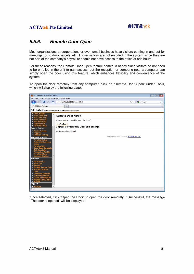
ACTAtek Pte Limited
ACTAtek3 Manual 81
8.5.6. Remote Door Open
Most organizations or corporations or even small business have visitors coming in and out for meetings, or to drop parcels, etc. Those visitors are not enrolled in the system since they are not part of the company’s payroll or should not have access to the office at odd hours. For these reasons, the Remote Door Open feature comes in handy since visitors do not need to be enrolled in the unit to gain access, but the reception or someone near a computer can simply open the door using this feature, which enhances flexibility and convenience of the system. To open the door remotely from any computer, click on “Remote Door Open” under Tools, which will display the following page:
Once selected, click “Open the Door” to open the door remotely. If successful, the message “The door is opened” will be displayed.
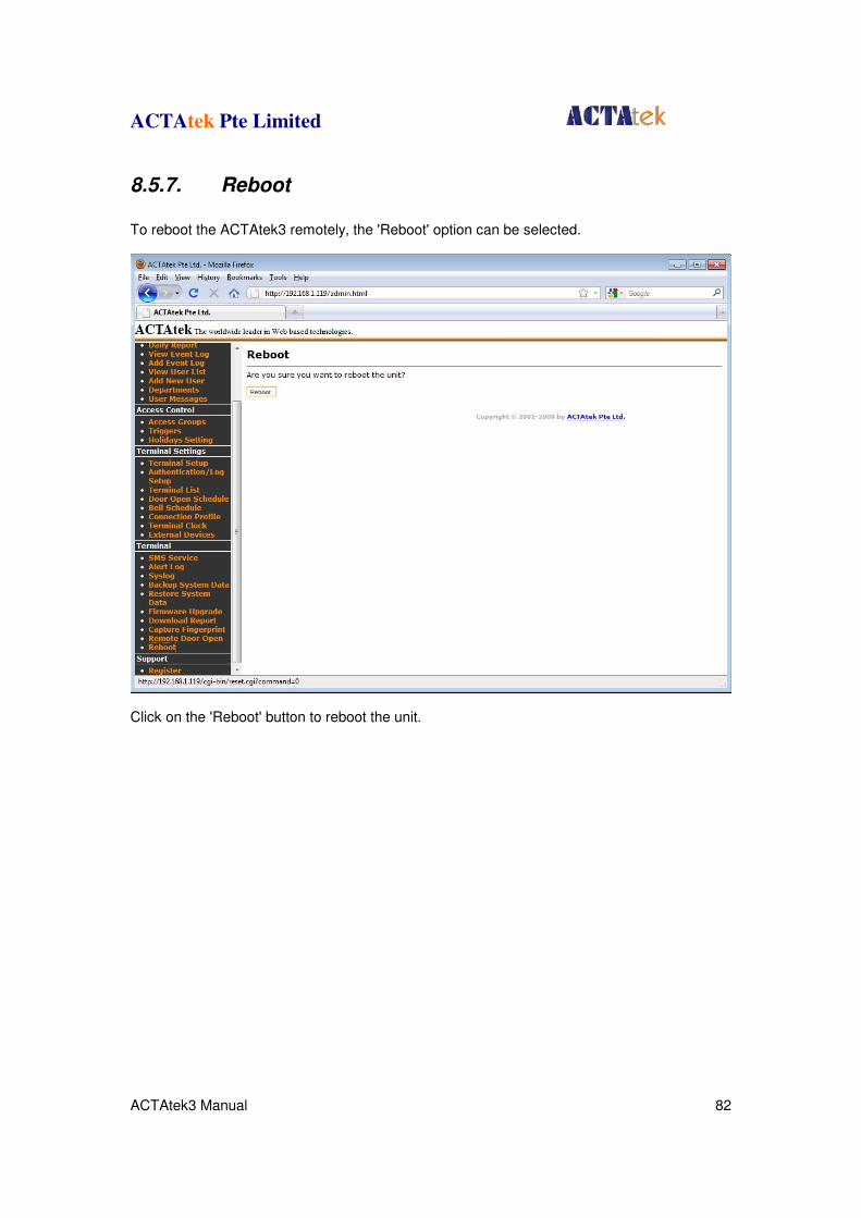
ACTAtek Pte Limited
ACTAtek3 Manual 82
8.5.7. Reboot
To reboot the ACTAtek3 remotely, the 'Reboot' option can be selected.
Click on the 'Reboot' button to reboot the unit.


![APKT_HMR Knowledge Transfer 20100519[1].pdf](https://img.pdfslide.net/doc/110x75/577cc4241a28aba7119840e9/apkthmr-knowledge-transfer-201005191pdf.jpg)