Embed Size (px)
Citation preview
2010/1/11
Lecture 1 on Extended Entity Relationship Model
This lecture is to describe the methodology of designing an Extended Entity Relationship Model as a conceptual schema for relational database with data semantics of weak entity, cardinality, isa, generalization, aggregation, participation, categorization and n-ary relationship.
2010/1/11
Database Design
A database is a model of an enterprise. It is an interface between people and machine. Their nature are utterly different. The design of a database must meet the needs of the people who use it and be practical in terms of technology and hardware. A database supports a community of users whose needs partly overlap, partly diverge and partly conflict. All these factors together constitute the complexity and difficulty of database design.
2010/1/11
Data ModelA data model is defined for describing the structure and processing of a
database. Database models have two major components:
1. Data definition language(DDL) is a database language that defines the structure of the database – data and relationship. It also provides facility for expressing a variety of user views and database constraints.
2. Data manipulation language(DML) is a database language for describing operations on the data that serve to express queries and other manipulation of data. Two types of DML exist:
• Procedural DML – describing actions to be performed (how).
• Nonprocedural DML – describing what data is wanted without describing how to obtain it.
2010/1/11
in
2010/1/11
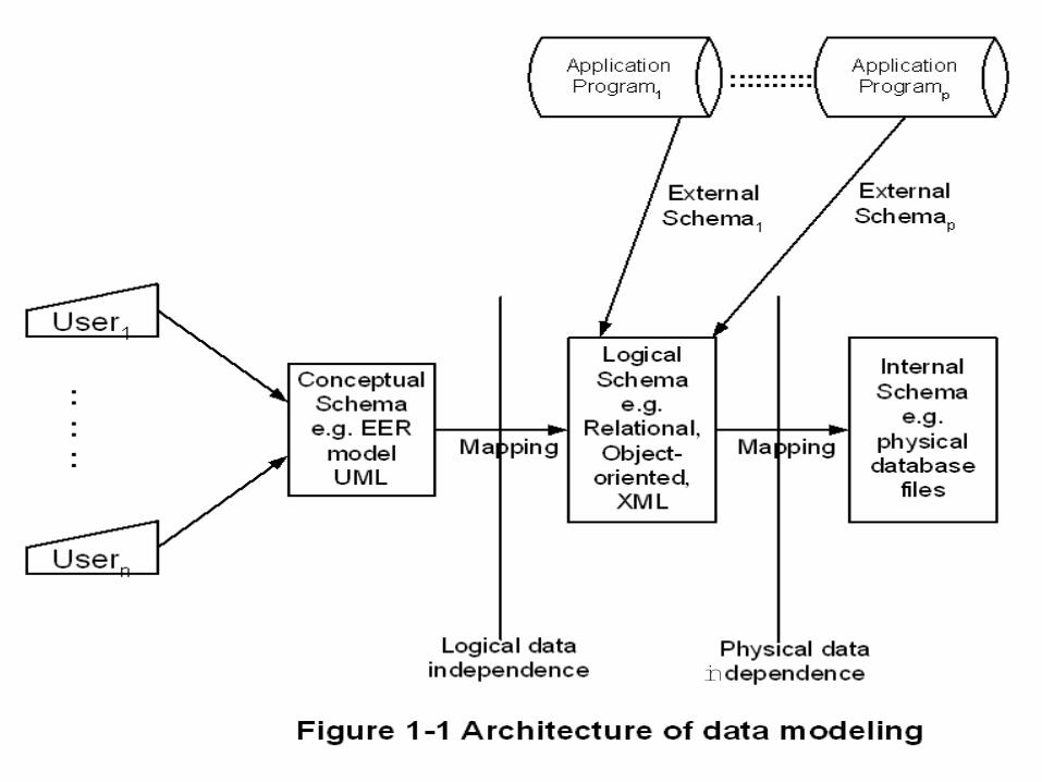
Data independence
1. Logical data independence – The changes of logical schema will not affect the view of the application program processing.
2. Physical data independence – The changes of the physical (internal) schema will not affect the application program processing.
2010/1/11
Application of data models to database designDatabase design can be summarized as follows:
1. Begin with the requirements definition.
2. Express tentative conceptual database design in terms of a logical database model.
3. Review design in light of requirements.
4. Convert conceptual design to a logical design using the appropriate logical data model, the one that matches the DBMS to be used.
5. Implement the database using the features of the DBMS.

2010/1/11
Use of models in database designSpecification
Entity-relationship or UML conceptual Schema
Relationship DefinitionsSupporting Documentation
Classes Diagrams and Supporting Documentation
Conceptual Design
Logical Design OR
Relational Database
implementation
Object-Oriented database
Implementation
Database Design
2010/1/11
Entity Relationship(ER) Model
The Entity Relationship Model is a diagramatic technique for conceptual database design. It serves as an informal representation to model the real world by adopting the more natural view that the real world consists of entities and relationship; and incorporating important semantic information into the model. The model can achieve a high degree of data independence and is based on set theory and relation theory. It can be used for designing conceptual database.
2010/1/11
Component of entity-relationship model1. Entity set – an entity set (i.e. entity type) or an entity (i.e. entity instance)
is an important distinguishable object for an application.
2. Entity key – an entity attribute that can uniquely identify an entity instance.
3. Entity attribute – fields that describe an entity.
4. Degree of relationship – the number of entity sets that are related to each other.
5. Cardinality – the data volume of two entities.
6. Relationship membership – the insertion rules of relationship, mandatory means compulsory relationship, optional means not compulsory relationship.
7. (Minimum, maximum) occurrence – the minimum and maximum instances of cardinality. (optional)
2010/1/11
Extended Entity Relationship(EER) Model
The ER model has been widely used but does not have some shortcomings. It is difficult to represent cases where an entity may have varying attributes dependent upon some property. Thus, ER model has been extended into Extended Entity Relationship model which includes more semantics such as generalization, categorization and aggregation.
2010/1/11
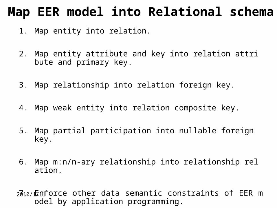
Map EER model into Relational schema
1. Map entity into relation.
2. Map entity attribute and key into relation attribute and primary key.
3. Map relationship into relation foreign key.
4. Map weak entity into relation composite key.
5. Map partial participation into nullable foreign key.
6. Map m:n/n-ary relationship into relationship relation.
7. Enforce other data semantic constraints of EER model by application programming.
2010/1/11
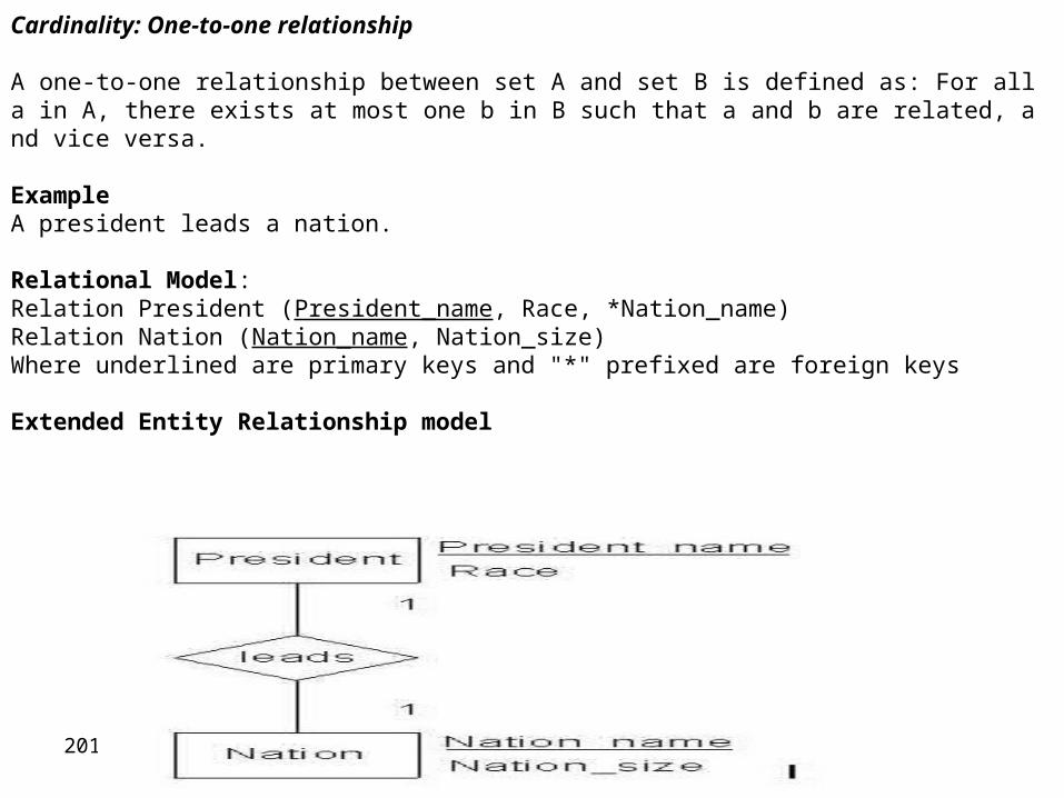
Cardinality: One-to-one relationship
A one-to-one relationship between set A and set B is defined as: For all a in A, there exists at most one b in B such that a and b are related, and vice versa.
ExampleA president leads a nation.
Relational Model:Relation President (President_name, Race, *Nation_name) Relation Nation (Nation_name, Nation_size) Where underlined are primary keys and "*" prefixed are foreign keys
Extended Entity Relationship model
2010/1/11
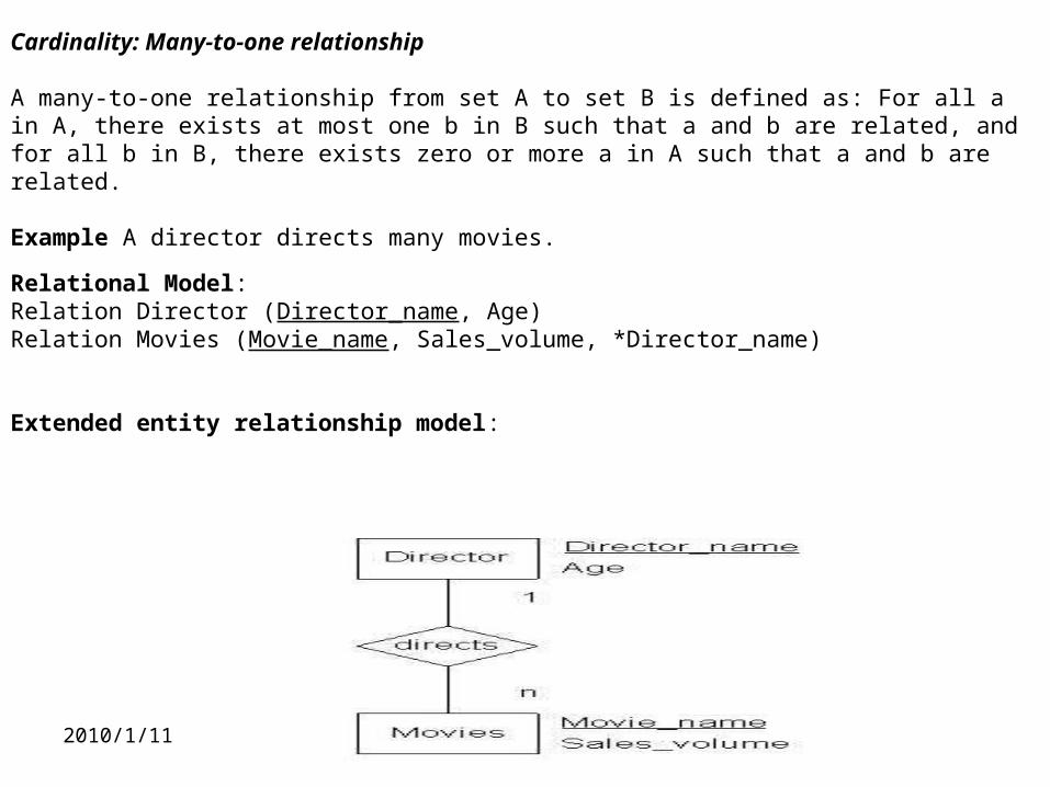
Cardinality: Many-to-one relationship
A many-to-one relationship from set A to set B is defined as: For all a in A, there exists at most one b in B such that a and b are related, and for all b in B, there exists zero or more a in A such that a and b are related.
Example A director directs many movies.
Relational Model:Relation Director (Director_name, Age) Relation Movies (Movie_name, Sales_volume, *Director_name)
Extended entity relationship model:
2010/1/11
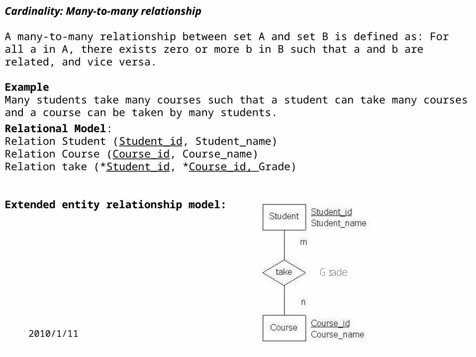
Cardinality: Many-to-many relationship
A many-to-many relationship between set A and set B is defined as: For all a in A, there exists zero or more b in B such that a and b are related, and vice versa.
ExampleMany students take many courses such that a student can take many courses and a course can be taken by many students.
Relational Model:Relation Student (Student_id, Student_name) Relation Course (Course_id, Course_name) Relation take (*Student_id, *Course_id, Grade)
Extended entity relationship model:
Grade
2010/1/11
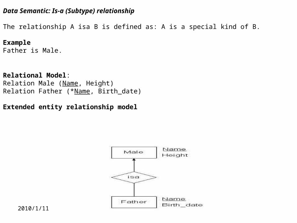
Data Semantic: Is-a (Subtype) relationship
The relationship A isa B is defined as: A is a special kind of B.
ExampleFather is Male.
Relational Model:Relation Male (Name, Height) Relation Father (*Name, Birth_date)
Extended entity relationship model
2010/1/11
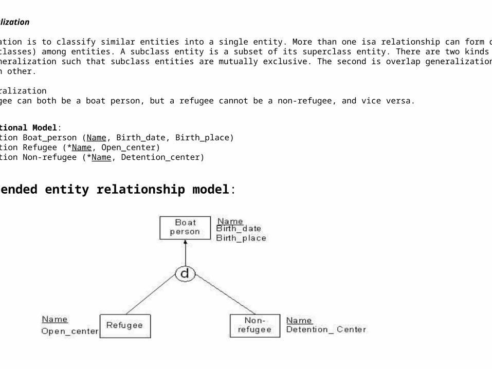
Data Semantic: Disjoint Generalization
The process of generalization is to classify similar entities into a single entity. More than one isa relationship can form data abstraction (i.e. superclass and subclasses) among entities. A subclass entity is a subset of its superclass entity. There are two kinds of generalization. The first is disjoint generalization such that subclass entities are mutually exclusive. The second is overlap generalization such that subclass entities can overlap each other.
Example of Disjoint GeneralizationA refugee and a non-refugee can both be a boat person, but a refugee cannot be a non-refugee, and vice versa.
Relational Model:Relation Boat_person (Name, Birth_date, Birth_place) Relation Refugee (*Name, Open_center) Relation Non-refugee (*Name, Detention_center)
Extended entity relationship model:
2010/1/11
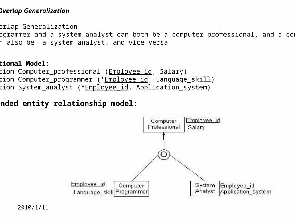
Data Semantic: Overlap Generalization
Example of Overlap GeneralizationA computer programmer and a system analyst can both be a computer professional, and a computer programmer can also be a system analyst, and vice versa.
Relational Model:Relation Computer_professional (Employee_id, Salary) Relation Computer_programmer (*Employee_id, Language_skill) Relation System_analyst (*Employee_id, Application_system)
Extended entity relationship model:
2010/1/11
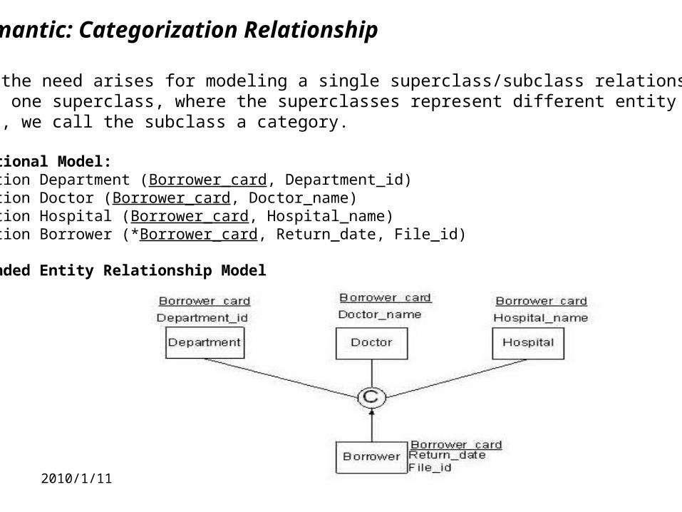
Data Semantic: Categorization Relationship
In cases the need arises for modeling a single superclass/subclass relationshipwith than one superclass, where the superclasses represent different entity types. In this case, we call the subclass a category.
Relational Model:Relation Department (Borrower_card, Department_id) Relation Doctor (Borrower_card, Doctor_name) Relation Hospital (Borrower_card, Hospital_name) Relation Borrower (*Borrower_card, Return_date, File_id)
Extended Entity Relationship Model
2010/1/11
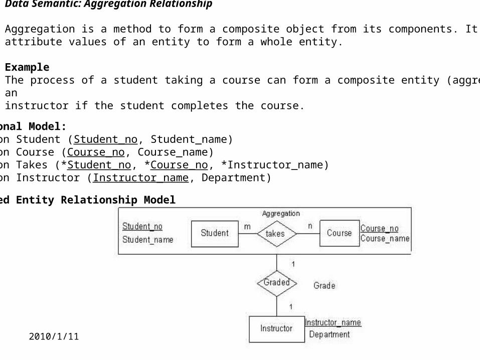
Data Semantic: Aggregation Relationship
Aggregation is a method to form a composite object from its components. It aggregates attribute values of an entity to form a whole entity.
Example The process of a student taking a course can form a composite entity (aggregation) that may be graded by an instructor if the student completes the course.
Relational Model:Relation Student (Student_no, Student_name) Relation Course (Course_no, Course_name) Relation Takes (*Student_no, *Course_no, *Instructor_name) Relation Instructor (Instructor_name, Department)
Extended Entity Relationship Model
2010/1/11
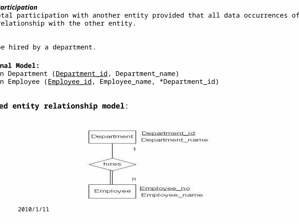
Data Semantic: Total ParticipationAn entity is in total participation with another entity provided that all data occurrences of the entity must participate in a relationship with the other entity.
Example An employee must be hired by a department.
Relational Model:Relation Department (Department_id, Department_name) Relation Employee (Employee_id, Employee_name, *Department_id)
Extended entity relationship model:
2010/1/11
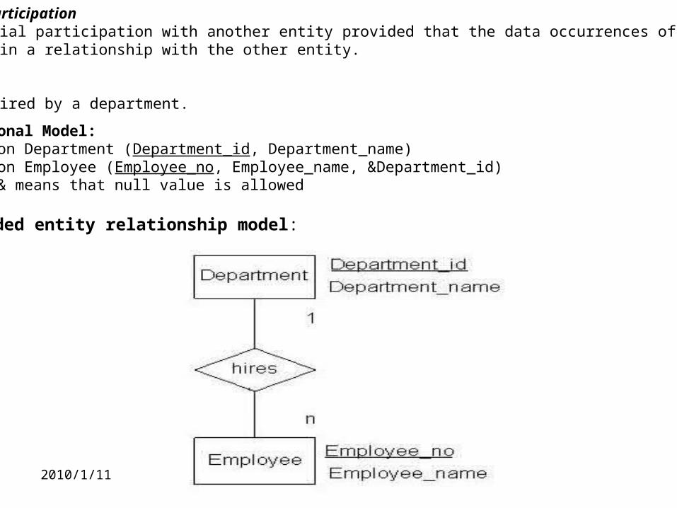
Data Semantic: Partial ParticipationAn entity is in partial participation with another entity provided that the data occurrences of the entity are not totally participate in a relationship with the other entity.
Example An employee may be hired by a department.
Relational Model:Relation Department (Department_id, Department_name) Relation Employee (Employee_no, Employee_name, &Department_id)Where & means that null value is allowed
Extended entity relationship model:
2010/1/12
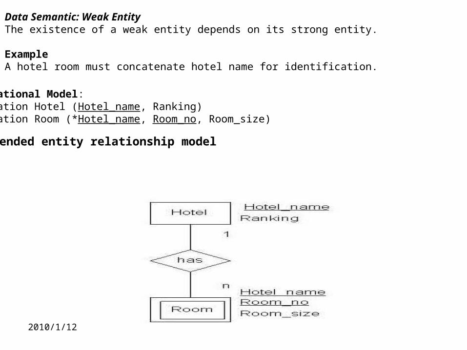
Data Semantic: Weak EntityThe existence of a weak entity depends on its strong entity.
ExampleA hotel room must concatenate hotel name for identification.
Relational Model:Relation Hotel (Hotel_name, Ranking) Relation Room (*Hotel_name, Room_no, Room_size)
Extended entity relationship model
2010/1/11
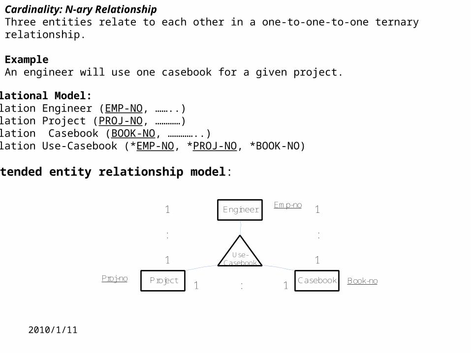
Cardinality: N-ary RelationshipThree entities relate to each other in a one-to-one-to-one ternary relationship.
Example An engineer will use one casebook for a given project.
Relational Model:Relation Engineer (EMP-NO, ……..) Relation Project (PROJ-NO, …………) Relation Casebook (BOOK-NO, …………..) Relation Use-Casebook (*EMP-NO, *PROJ-NO, *BOOK-NO)
Extended entity relationship model:
Engineer
Project Casebook
Use-Casebook
1
1
1
1
1 1
: :
:
Emp-no
Book-noProj-no
2010/1/11
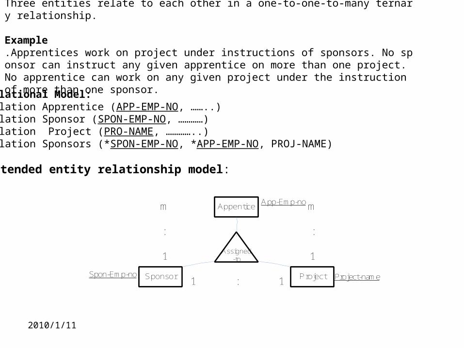
Cardinality: N-ary RelationshipThree entities relate to each other in a one-to-one-to-many ternary relationship.
Example .Apprentices work on project under instructions of sponsors. No sponsor can instruct any given apprentice on more than one project. No apprentice can work on any given project under the instruction of more than one sponsor.
Relational Model:Relation Apprentice (APP-EMP-NO, ……..) Relation Sponsor (SPON-EMP-NO, …………) Relation Project (PRO-NAME, …………..) Relation Sponsors (*SPON-EMP-NO, *APP-EMP-NO, PROJ-NAME)
Extended entity relationship model:
Appentice
Sponsor Project
Assigned-to
m
1
m
1
1 1
: :
:
App-Emp-no
Project-nameSpon-Emp-no
2010/1/11
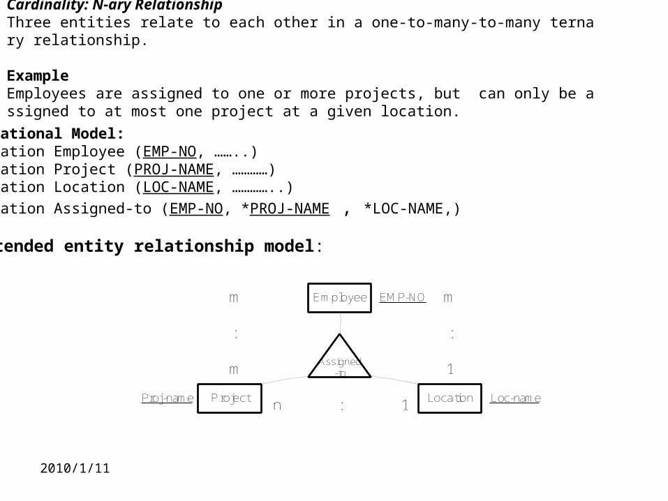
Cardinality: N-ary RelationshipThree entities relate to each other in a one-to-many-to-many ternary relationship.
Example Employees are assigned to one or more projects, but can only be assigned to at most one project at a given location.
Relational Model:Relation Employee (EMP-NO, ……..) Relation Project (PROJ-NAME, …………) Relation Location (LOC-NAME, …………..)
Relation Assigned-to (EMP-NO, *PROJ-NAME , *LOC-NAME,)
Extended entity relationship model:
Employee
Project Location
Assigned-to
m
m
m
1
n 1
: :
:
EMP-NO
Loc-nameProj-name
2010/1/11
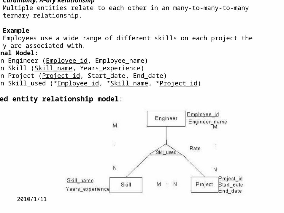
Cardinality: N-ary RelationshipMultiple entities relate to each other in an many-to-many-to-many ternary relationship.
Example Employees use a wide range of different skills on each project they are associated with .
Relational Model:Relation Engineer (Employee_id, Employee_name) Relation Skill (Skill_name, Years_experience) Relation Project (Project_id, Start_date, End_date) Relation Skill_used (*Employee_id, *Skill_name, *Project_id)
Extended entity relationship model:
2010/1/11
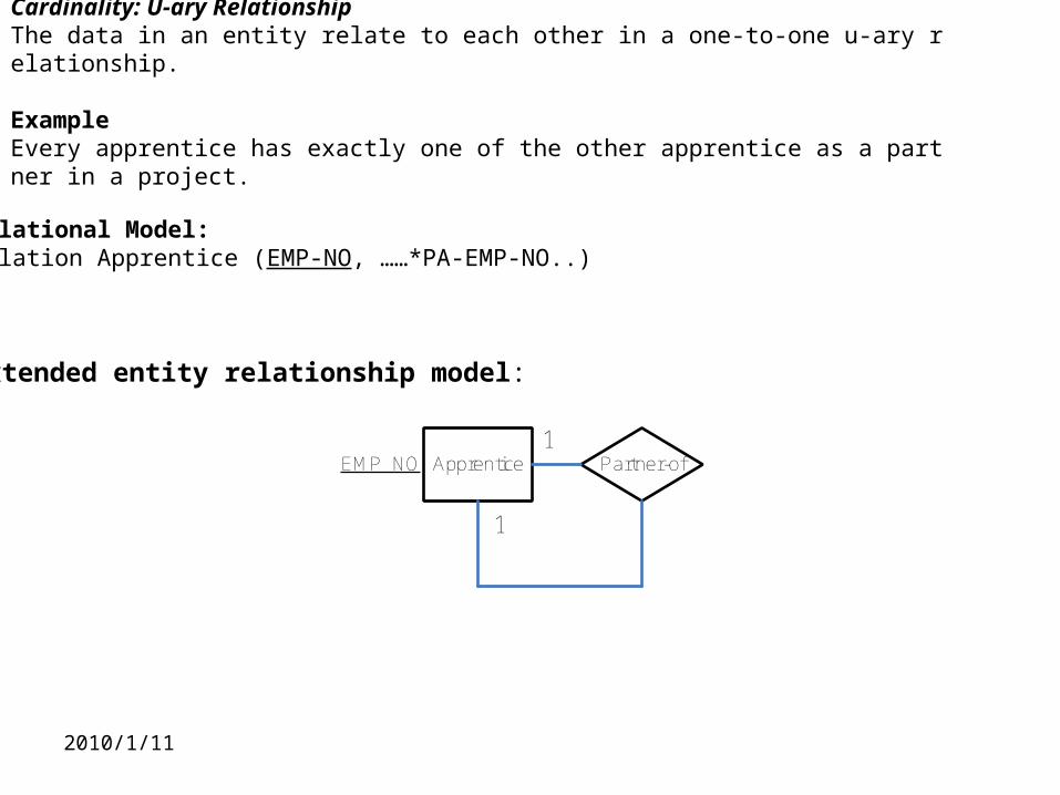
Cardinality: U-ary RelationshipThe data in an entity relate to each other in a one-to-one u-ary relationship.
Example Every apprentice has exactly one of the other apprentice as a partner in a project.
Relational Model:Relation Apprentice (EMP-NO, ……*PA-EMP-NO..)
Extended entity relationship model:
Apprentice Partner-of
1
1EMP_NO
2010/1/11
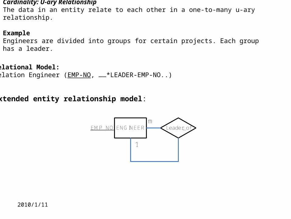
Cardinality: U-ary RelationshipThe data in an entity relate to each other in a one-to-many u-ary relationship.
Example Engineers are divided into groups for certain projects. Each group has a leader.
Relational Model:Relation Engineer (EMP-NO, ……*LEADER-EMP-NO..)
Extended entity relationship model:
ENGINEER Leader_of
1
mEMP_NO
2010/1/11
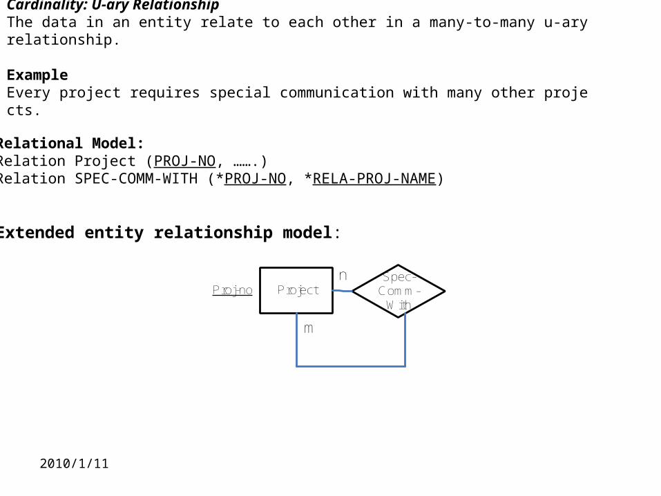
Cardinality: U-ary RelationshipThe data in an entity relate to each other in a many-to-many u-ary relationship.
Example Every project requires special communication with many other projects.
Relational Model:Relation Project (PROJ-NO, …….) Relation SPEC-COMM-WITH (*PROJ-NO, *RELA-PROJ-NAME)
Extended entity relationship model:
ProjectSpec-
Comm-With
m
nProj-no
2010/1/11
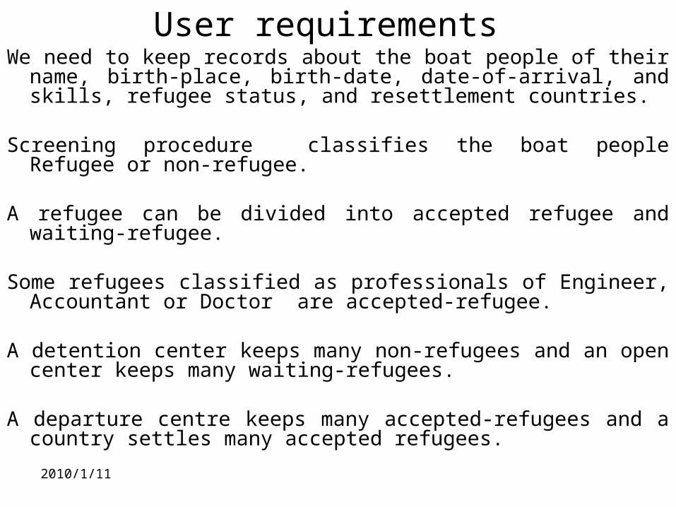
User requirements We need to keep records about the boat people of their name, birth-
place, birth-date, date-of-arrival, and skills, refugee status, and resettlement countries.
Screening procedure classifies the boat people Refugee or non-refugee.
A refugee can be divided into accepted refugee and waiting-refugee.
Some refugees classified as professionals of Engineer, Accountant or Doctor are accepted-refugee.
A detention center keeps many non-refugees and an open center keeps many waiting-refugees.
A departure centre keeps many accepted-refugees and a country settles many accepted refugees.
2010/1/12
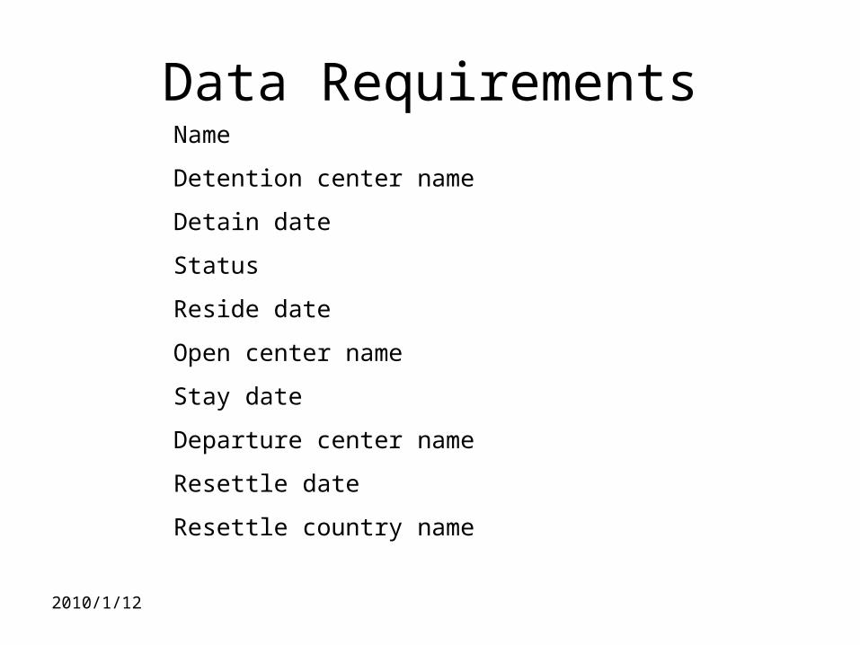
Data RequirementsName
Detention center name
Detain date
Status
Reside date
Open center name
Stay date
Departure center name
Resettle date
Resettle country name
2010/1/11
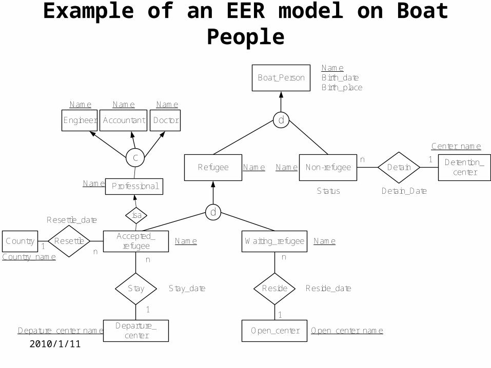
Example of an EER model on Boat People
Boat_Person
Refugee Non-refugee
d
Detention_center
Detain
Waiting_refugeeAccepted_
refugee
d
Open_center
Reside
Departure_center
Stay
Country Resettle
Engineer Accountant Doctor
c
NameBirth_dateBirth_place
Status Detain_Date
Reside_dateStay_date
Resettle_date
Name
Name
Name
Name
NameNameName
Center_name
Open_center_nameDepature_center_name
Country_namen
n
n
1
1
n
1
1
Professional
isa
Name
2010/1/12
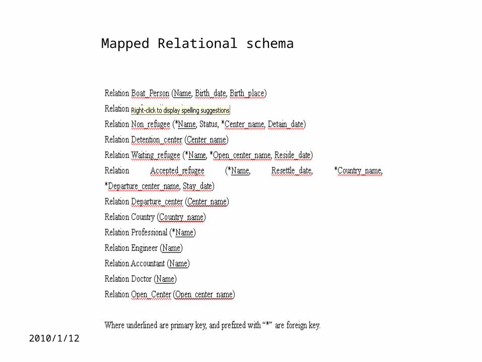
Mapped Relational schema
2010/1/11
Summary of lecture
In general, a user needs to specify his/her data requirements in terms of data semantics and presents them in the form of an Extended Entity Relationship Model. Each noun of the data requirements is potentially an Entity and each verb of the data requirements is potentially an relationship which can be u-ary (1 entity), binary (2 entities) and ternary (3 entities).
2010/1/11
Review Question 1
Describe the data semantics of Generalization and Categorization.
What are the major differences between Generalization and Categorization in terms of data volume in their related superclass and subclass entities?
Is there any special case such that these two data semantics can be overlapped in their data volume?
2010/1/11
Make-up Tutorial Question 1Identify the entities and relationships for the following enterprise and draw its E
xtended Entity Relationship Model.
A person (identified by PERSON-ID) can originate an ORDER (identified by ORDER-ID) in the enterprise. Each ORDER is originated by one PERSON, but one PERSON can originate more than one ORDER. Each ORDER is associated with one SUPPLIER (identified by SUPPLIER-NO). A SUPPLIER can be in many ORDERs. Each ORDER is made up of any number of ITEM kinds (identified by ITEM-ID). An ITEM kind can appear in any number of ORDERs; ITEM-QTY is the quantity of an ITEM in a particular ORDER.
A quantity of any ITEM in an ORDER can be allocated to a PROJECT (identified by PROJECT-NO) in the enterprise. A PROJECT can use the same ITEM kind from different ORDERs; one ITEM kind in an ORDER can be used in a number of PROJECTs. ITEM-USED-IN-PROJECT is the total amount of some ITEM kind in a PROJECT; ITEM-IN-ORDER-USED-IN-PROJECT is the amount of ITEM kind within an ORDER used by a PROJECT. Note that more than one PROJECT can use the same ITEM kind from the one ORDER.
2010/1/11
Reading Assignment
Chapter 4 The Enhanced Entity-Relationship Model “Fundamentals of Database Systems” by Elmasri & Navathe, Pearson, 2007.