Embed Size (px)
Citation preview
1
Chapter 5
Objectives: to learn about
– the extended entity relationship (E-ER) model
– How entity clusters are used to represent multiple entities and relationships
– The characteristics of good primary keys and how to select them
– using flexible solutions for special data modeling cases
1CS275 Fall 2010
The Extended Entity
Relationship Model
• Result of adding more semantic constructs to
original entity relationship (ER) model
• Diagram using this model is called an EER
diagram (EERD)
• Combines some of the Object-oriented concepts
with Entity Relationship concepts.
2CS275 Fall 2010
Entity Supertypes and Subtypes
• Entity supertype
– Generic entity type related to one or more entity
subtypes
– Contains common characteristics
• Entity subtype
– Contains unique characteristics of each entity
subtype
– Avoids unnecessary null attributes when not
shared by all super entity types.
3CS275 Fall 2010
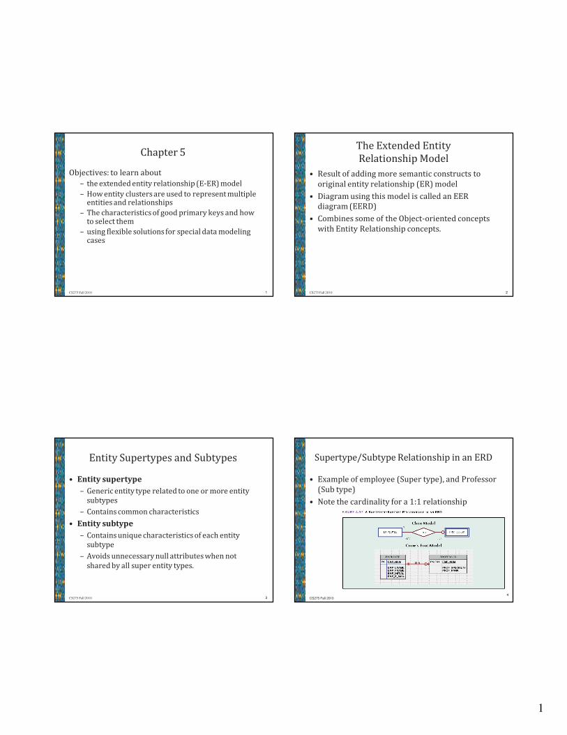
Supertype/Subtype Relationship in an ERD
• Example of employee (Super type), and Professor
(Sub type)
• Note the cardinality for a 1:1 relationship
4
CS275 Fall 2010
2
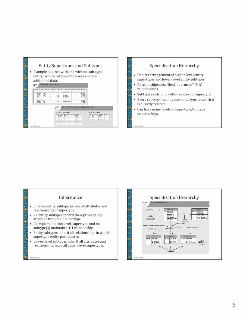
Entity Supertypes and Subtypes
• Example data set with and without sub-type
entity, where certain employees contain
additional data.
5CS275 Fall 2010
Specialization Hierarchy
• Depicts arrangement of higher-level entity
supertypes and lower-level entity subtypes
• Relationships described in terms of “IS-A”
relationships
• Subtype exists only within context of supertype
• Every subtype has only one supertype to which it
is directly related
• Can have many levels of supertype/subtype
relationships
6CS275 Fall 2010
Inheritance
• Enables entity subtype to inherit attributes and relationships of supertype
• All entity subtypes inherit their primary key attribute from their supertype
• At implementation level, supertype and its subtype(s) maintain a 1:1 relationship
• Entity subtypes inherit all relationships in which supertype entity participates
• Lower-level subtypes inherit all attributes and relationships from all upper-level supertypes
7CS275 Fall 2010
Specialization Hierarchy
8CS275 Fall 2010
3
Subtype Discriminator
• The Subtype Discriminator is an attribute in
supertype entity
– Determines to which entity subtype each
supertype occurrence is related
• Default comparison condition for subtype
discriminator attribute is equality comparison
• Subtype discriminator may be based on other
comparison condition
9CS275 Fall 2010
Disjoint and Overlapping Constraints
• Disjoint subtypes
– Also called nonoverlapping subtypes
– Subtypes that contain unique subset of supertype
entity set
– Single attribute is coded for the type
• Overlapping subtypes
– Subtypes that contain non-unique subsets of
supertype entity set
– Multiple attributes are necessary, each
representing a possible type.
10CS275 Fall 2010
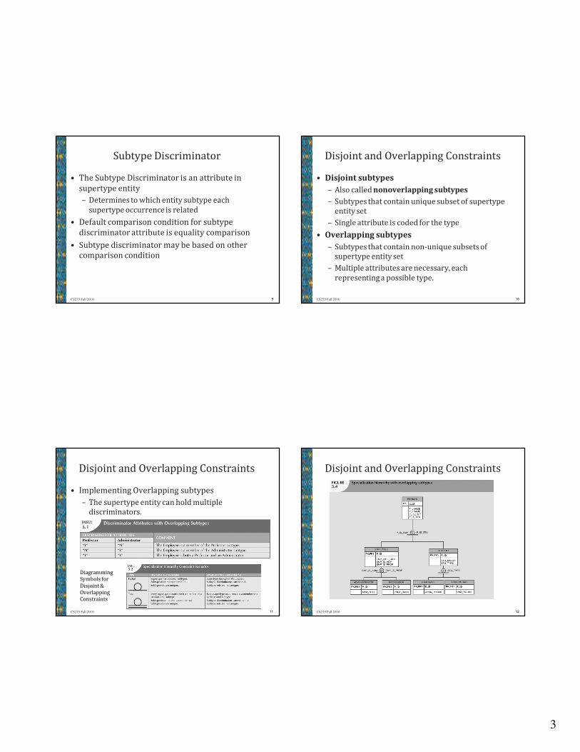
Disjoint and Overlapping Constraints
• Implementing Overlapping subtypes
– The supertype entity can hold multiple
discriminators.
11CS275 Fall 2010
Diagramming
Symbols for
Disjoint &
Overlapping
Constraints
Disjoint and Overlapping Constraints
12CS275 Fall 2010
4
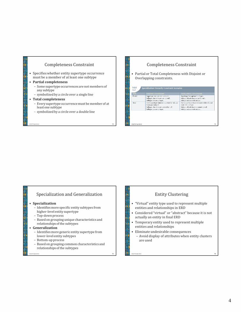
Completeness Constraint
• Specifies whether entity supertype occurrence must be a member of at least one subtype
• Partial completeness
– Some supertype occurrences are not members of any subtype
– symbolized by a circle over a single line
• Total completeness
– Every supertype occurrence must be member of at least one subtype
– symbolized by a circle over a double line
13CS275 Fall 2010
Completeness Constraint
• Partial or Total Completeness with Disjoint or
Overlapping constraints.
14CS275 Fall 2010
Specialization and Generalization
• Specialization– Identifies more specific entity subtypes from
higher-level entity supertype
– Top-down process
– Based on grouping unique characteristics and
relationships of the subtypes
• Generalization– Identifies more generic entity supertype from
lower-level entity subtypes
– Bottom-up process
– Based on grouping common characteristics and
relationships of the subtypes
15CS275 Fall 2010
Entity Clustering
• “Virtual” entity type used to represent multiple
entities and relationships in ERD
• Considered “virtual” or “abstract” because it is not
actually an entity in final ERD
• Temporary entity used to represent multiple
entities and relationships
• Eliminate undesirable consequences
– Avoid display of attributes when entity clusters
are used
16CS275 Fall 2010

5
Entity Clustering
• A technique used to
simplify the ERD
◦ Useful when the target
audience of the ERD is
not directly involved
with the subsystem
represented by the
virtual entity.
◦ Makes sure that the
relationship to the
cluster is not forgotten.
17CS275 Fall 2010
Selecting Primary Keys
• Primary key is the most important characteristic
of an entity
– Single attribute or some combination of attributes
• Primary key’s function is to guarantee entity
integrity, i.e. the uniqueness of each entity row.
• It’s purpose is to guarantee uniqueness, not to
“describe” the entity
• Primary keys and foreign keys work together to
implement relationships
• Properly selecting primary key has direct bearing
on efficiency and effectiveness18CS275 Fall 2010
Primary Key Guidelines
19CS275 Fall 2010
Selecting Primary Keys
• A Natural key is a real-world identifier used to
uniquely identify real-world objects– Familiar to end users and forms part of their day-
to-day business vocabulary
– is generally used as the primary key of entity
being modeled
• Composite keys are useful in two cases:– As identifiers of composite(bridge) entities
– As identifiers of weak entities
• Surrogate keys may be generated when a
Natural or Composite key is not available.
20CS275 Fall 2010
6
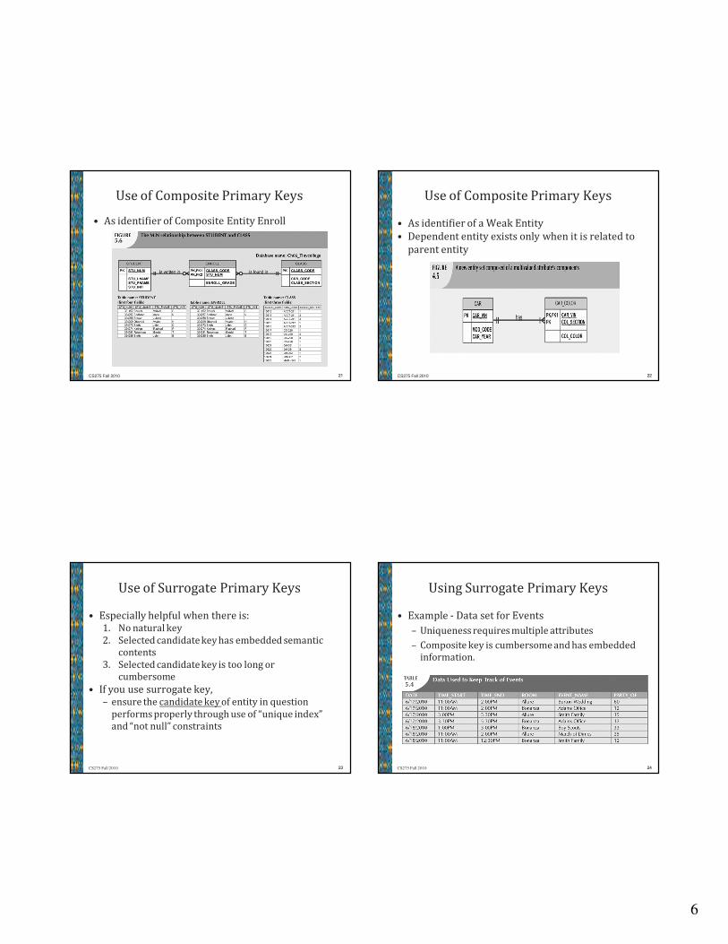
Use of Composite Primary Keys
• As identifier of Composite Entity Enroll
21CS275 Fall 2010
Use of Composite Primary Keys
• As identifier of a Weak Entity
• Dependent entity exists only when it is related to
parent entity
22CS275 Fall 2010
Use of Surrogate Primary Keys
• Especially helpful when there is:1. No natural key
2. Selected candidate key has embedded semantic
contents
3. Selected candidate key is too long or
cumbersome
• If you use surrogate key, – ensure the candidate key of entity in question
performs properly through use of “unique index”
and “not null” constraints
23CS275 Fall 2010
Using Surrogate Primary Keys
• Example - Data set for Events
– Uniqueness requires multiple attributes
– Composite key is cumbersome and has embedded
information.
24CS275 Fall 2010
7
Design Cases:
Learning Flexible Database Design
• Data modeling and design requires skills
acquired through experience
• Experience acquired through practice
• Four special design cases that highlight:
– Importance of flexible design
– Proper identification of primary keys
– Placement of foreign keys
25CS275 Fall 2010
Design Case #1:
Implementing 1:1 Relationships
• Foreign keys work with primary keys to properly
implement relationships in relational model
• Although conceivable to have put the primary key
of each table into the other table as a foreign key,
it is unnecessary.
• Put primary key of the “one” side (parent entity)
on the “many” side (dependent entity) as foreign
key
26CS275 Fall 2010
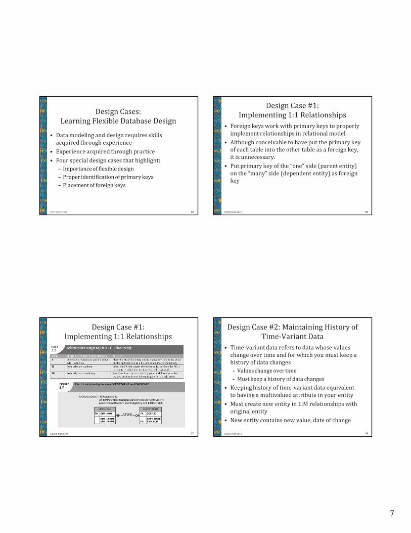
Design Case #1:
Implementing 1:1 Relationships
27CS275 Fall 2010
Design Case #2: Maintaining History of
Time-Variant Data
• Time-variant data refers to data whose values
change over time and for which you must keep a
history of data changes
– Values change over time
– Must keep a history of data changes
• Keeping history of time-variant data equivalent
to having a multivalued attribute in your entity
• Must create new entity in 1:M relationships with
original entity
• New entity contains new value, date of change
28CS275 Fall 2010
8
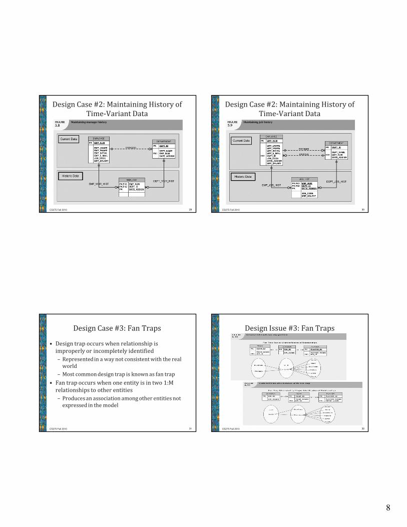
Design Case #2: Maintaining History of
Time-Variant Data
29CS275 Fall 2010
Design Case #2: Maintaining History of
Time-Variant Data
30CS275 Fall 2010
Design Case #3: Fan Traps
• Design trap occurs when relationship is
improperly or incompletely identified
– Represented in a way not consistent with the real
world
– Most common design trap is known as fan trap
• Fan trap occurs when one entity is in two 1:M
relationships to other entities
– Produces an association among other entities not
expressed in the model
31CS275 Fall 2010
Design Issue #3: Fan Traps
32CS275 Fall 2010
9
Design Case #4:
Redundant Relationships
• Redundancy is seldom a good thing in database
environment
– Occurs when there are multiple relationship paths
between related entities
• Some designs use redundant relationships to
simplify the design, or to account for time-variant
data.
• The concern is that redundant relationships
remain consistent across model
33CS275 Fall 2010
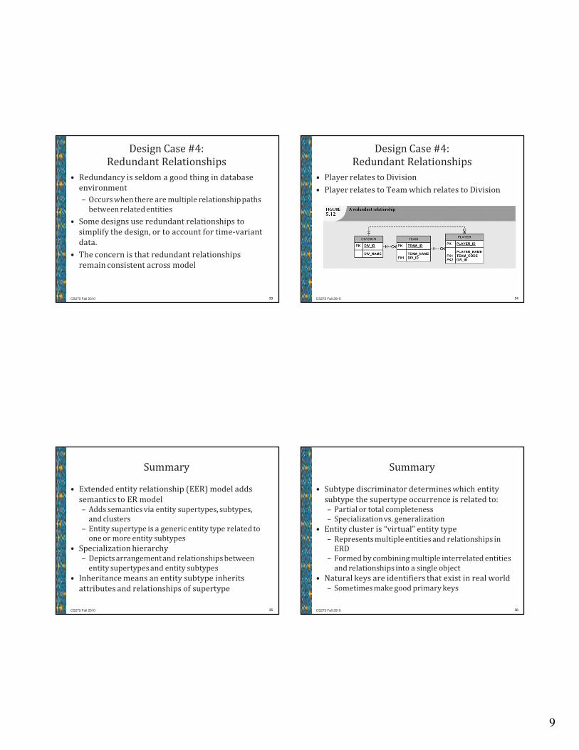
Design Case #4:
Redundant Relationships
• Player relates to Division
• Player relates to Team which relates to Division
34CS275 Fall 2010
Summary
• Extended entity relationship (EER) model adds
semantics to ER model– Adds semantics via entity supertypes, subtypes,
and clusters
– Entity supertype is a generic entity type related to
one or more entity subtypes
• Specialization hierarchy – Depicts arrangement and relationships between
entity supertypes and entity subtypes
• Inheritance means an entity subtype inherits
attributes and relationships of supertype
35CS275 Fall 2010
Summary
• Subtype discriminator determines which entity
subtype the supertype occurrence is related to:– Partial or total completeness
– Specialization vs. generalization
• Entity cluster is “virtual” entity type
– Represents multiple entities and relationships in
ERD
– Formed by combining multiple interrelated entities
and relationships into a single object
• Natural keys are identifiers that exist in real world– Sometimes make good primary keys
36CS275 Fall 2010
10
Summary
• Characteristics of primary keys:– Must have unique values
– Should be nonintelligent
– Must not change over time
– Preferably numeric or composed of single
attribute
• Composite keys are useful to represent – M:N relationships
– Weak (strong-identifying) entities
• Surrogate primary keys are useful when no
suitable natural key makes primary key
37CS275 Fall 2010
Summary
• For 1:1 relationship, put the PK of mandatory
entity– As FK in optional entity
– As FK in entity that causes least number of nulls
– As FK where the role is played
• Time-variant data – Data whose values change over time
– Requires keeping a history of changes
• To maintain history of time-variant data:– Create entity containing the new value, date of
change, other time-relevant data
– Entity maintains 1:M relationship with entity for
which history maintained38CS275 Fall 2010
Summary
• Fan trap:– One entity in two 1:M relationships to other entities
– Association among the other entities not expressed
in model
• Redundant relationships occur when multiple
relationship paths between related entities– Main concern is that they remain consistent across
the model
• Data modeling checklist provides way to check that
the ERD meets minimum requirements (see the
front cover, inside page)
39CS275 Fall 2010