Embed Size (px)
Citation preview

Engineering Freedom.
Nemetschek Engineering User Contest 2011
Nemetschek Engineering User Contest 2011
Nemetschek Allplan Konrad-Zuse-Platz 1 - D-81829 München Tel: +49 89 92793-0 - Fax: +49 89 92793-5200 [email protected]
Nemetschek Engineering (Allplan Precast) Stadionstrasse 6 - A-5071 Wals-Siezenheim Tel: +43 662 854111 - Fax: +43 662 854111610 [email protected]
Nemetschek Scia Industrieweg 1007 - B-3540 Herk-de-Stad Tel: +32 13 55 17 75 - Fax: +32 13 55 41 75 [email protected]
Nemetschek Frilo Stuttgarter Straße 36 - D-70469 Stuttgart Tel: +49 711 81002-0 - Fax: +49 711 858020 [email protected]
GLASER -isb cad- Am Waldwinkel 21 - D-30974 Wennigsen Tel: +49 5105 5892-0 - Fax: +49 5105 82943 [email protected]


1
Foreword
With 117 impressive projects from over 23 countries, the Nemetschek Engineering Contest 2011 is again a big success. The projects described in the contest book illustrate the engineering power of our customers who are increasingly internationally active.
The software users competed with projects in five categories: Buildings, Civil Structures, Industrial Buildings and Plants, Industrialized Planning and Special Projects (sustainable, green structures - scaffolding - stadiums...). A variety of software from the Nemetschek Engineering Group has been used: Allplan Engineering, Scia Engineer, Frilo Statics, GLASER -isb cad-, Allplan Precast, Precast Part Manager and/or Scia Steel. The Nemetschek Engineering Group software covers the whole spectrum of structural engineering design and detailing: from member design and detailing up to 3D BIM (Building Information Modelling) and integrated fabrication planning and steering.
The Nemetschek User Contest 2011 book gives a close insight on how structures are planned and executed today. We congratulate sincerely the contest winners, and have to thank all contest participants for sharing their experiences with the large Nemetschek Engineering user community.
Ernst Homolka Jean-Pierre Rammant, dr.ir.CEO of Nemetschek AG CEO of Nemetschek Scia and leader of the Nemetschek Engineering Group

2
Table of Contents
Foreword . . . . . . . . . . . . . . . . . . . . . . . . . . . . . . . . . . . . . . . . . . . . . . . . . . . . . . . . . . . . . . . . . . . . . . . . . . . . . . . . . . . . . . . . . . . . . . . . . . . . . . . . . . . . . . . . . . . . . . . . . . . . . . . . . . . . . . . . . . . . . . . . . . . . . . . . . . . . . . . . . . . . . . . . . . . . . . . . . 1Table of Contents. . . . . . . . . . . . . . . . . . . . . . . . . . . . . . . . . . . . . . . . . . . . . . . . . . . . . . . . . . . . . . . . . . . . . . . . . . . . . . . . . . . . . . . . . . . . . . . . . . . . . . . . . . . . . . . . . . . . . . . . . . . . . . . . . . . . . . . . . . . . . . . . . . . . . . . . . . . . . . . . . . . . . . . . 4Winners . . . . . . . . . . . . . . . . . . . . . . . . . . . . . . . . . . . . . . . . . . . . . . . . . . . . . . . . . . . . . . . . . . . . . . . . . . . . . . . . . . . . . . . . . . . . . . . . . . . . . . . . . . . . . . . . . . . . . . . . . . . . . . . . . . . . . . . . . . . . . . . . . . . . . . . . . . . . . . . . . . . . . . . . . . . . . . . . . . . 7The Nemetschek Engineering Group . . . . . . . . . . . . . . . . . . . . . . . . . . . . . . . . . . . . . . . . . . . . . . . . . . . . . . . . . . . . . . . . . . . . . . . . . . . . . . . . . . . . . . . . . . . . . . . . . . . . . . . . . . . . . . . . . . . . . . . . . . . . . . . . . . . . . . . . . . . . . . . . . 8Categories and Jury. . . . . . . . . . . . . . . . . . . . . . . . . . . . . . . . . . . . . . . . . . . . . . . . . . . . . . . . . . . . . . . . . . . . . . . . . . . . . . . . . . . . . . . . . . . . . . . . . . . . . . . . . . . . . . . . . . . . . . . . . . . . . . . . . . . . . . . . . . . . . . . . . . . . . . . . . . . . . . . . . . . . . 10
Category 1: Buildings . . . . . . . . . . . . . . . . . . . . . . . . . . . . . . . . . . . . . . . . . . . . . . . . . . . . . . . . . . . . . . . . . . . . . . . . . . . . . . . . . . . . . . . . . . . . . . . . . . . . . . . . . . . . . . . . . . . . . . . . . . . . . . . . . . . . . . . . . . . . . . . . . . . . . . . . . . . . . . . . . . . 13W Prodis plus s.r.o. . . . . . . . . . . . . . . . . . . . . . . . . . . . . . . . . . . . . . . . . . . . . . . . . . . . . . . . . River House - Bratislava, Slovak Republic . . . . . . . . . . . . . . . . . . . . . . . . . . . . . . . . . . . . . . . . . . . . . . . . . . . . . . . . . . . 14J Inginerie Structurala srl . . . . . . . . . . . . . . . . . . . . . . . . . . . . . . . . . . . . . . . . . . . . . . . . Orchidea Tower - Bucharest, Romania . . . . . . . . . . . . . . . . . . . . . . . . . . . . . . . . . . . . . . . . . . . . . . . . . . . . . . . . . . . . 16N BESIX . . . . . . . . . . . . . . . . . . . . . . . . . . . . . . . . . . . . . . . . . . . . . . . . . . . . . . . . . . . . . . . . . . . . Adnoc HQ Tower - Abu Dhabi, United Arab Emirates . . . . . . . . . . . . . . . . . . . . . . . . . . . . . . . . . . . . . . . . . . . . . . . 18N Conserela UAB . . . . . . . . . . . . . . . . . . . . . . . . . . . . . . . . . . . . . . . . . . . . . . . . . . . . . . . . . Office Blocks Gedimino 35 - Vilnius, Lithuania . . . . . . . . . . . . . . . . . . . . . . . . . . . . . . . . . . . . . . . . . . . . . . . . . . . 20N Thomasons . . . . . . . . . . . . . . . . . . . . . . . . . . . . . . . . . . . . . . . . . . . . . . . . . . . . . . . . . . . . . St Mary of the Angels Primary School - London, United Kingdom . . . . . . . . . . . . . . . . . . . . . . . . . . . . . . . . 22
Adams Bouwadviesbureau bv . . . . . . . . . . . . . . . . . . . . . . . . . . . . . . . . . . . . . . . . Five Flats and Shop-Premises - Druten, The Netherlands . . . . . . . . . . . . . . . . . . . . . . . . . . . . . . . . . . . . . . 24Adviesburo de Kwaadsteniet. . . . . . . . . . . . . . . . . . . . . . . . . . . . . . . . . . . . . . . . . . Showroom Habufa - Hapert, The Netherlands . . . . . . . . . . . . . . . . . . . . . . . . . . . . . . . . . . . . . . . . . . . . . . . . . . . . 26AECOM . . . . . . . . . . . . . . . . . . . . . . . . . . . . . . . . . . . . . . . . . . . . . . . . . . . . . . . . . . . . . . . . . . Heartlands High School - London, United Kingdom. . . . . . . . . . . . . . . . . . . . . . . . . . . . . . . . . . . . . . . . . . . . . . . . . 28BARAN PROJEKT s.r.o. . . . . . . . . . . . . . . . . . . . . . . . . . . . . . . . . . . . . . . . . . . . . . . . Mirage Shopping Center - Zilina, Slovak Republic . . . . . . . . . . . . . . . . . . . . . . . . . . . . . . . . . . . . . . . . . . . . . . . . . . 30BG Ingénieurs Conseils . . . . . . . . . . . . . . . . . . . . . . . . . . . . . . . . . . . . . . . . . . . . . . . Villa-les-bains - Montreux, Switzerland . . . . . . . . . . . . . . . . . . . . . . . . . . . . . . . . . . . . . . . . . . . . . . . . . . . . . . . . . . . . . . . 32Bureau d’Etudes ADAM . . . . . . . . . . . . . . . . . . . . . . . . . . . . . . . . . . . . . . . . . . . . . . . Naïade Tornacum - Tournai, Belgium . . . . . . . . . . . . . . . . . . . . . . . . . . . . . . . . . . . . . . . . . . . . . . . . . . . . . . . . . . . . . . . . . 34Bureau d’Etudes Lemaire sprl . . . . . . . . . . . . . . . . . . . . . . . . . . . . . . . . . . . . . . . . Crematorium - Welkenraedt, Belgium . . . . . . . . . . . . . . . . . . . . . . . . . . . . . . . . . . . . . . . . . . . . . . . . . . . . . . . . . . . . . . . . . 36Bureau d’Etudes Lemaire sprl . . . . . . . . . . . . . . . . . . . . . . . . . . . . . . . . . . . . . . . . Technifutur Tower - Liège, Belgium . . . . . . . . . . . . . . . . . . . . . . . . . . . . . . . . . . . . . . . . . . . . . . . . . . . . . . . . . . . . . . . . . . . . 38Constructa Ltd . . . . . . . . . . . . . . . . . . . . . . . . . . . . . . . . . . . . . . . . . . . . . . . . . . . . . . . . . . Extension of the Oncological Hospital - Ruse, Bulgaria . . . . . . . . . . . . . . . . . . . . . . . . . . . . . . . . . . . . . . . . . . . . 40Constructa Ltd . . . . . . . . . . . . . . . . . . . . . . . . . . . . . . . . . . . . . . . . . . . . . . . . . . . . . . . . . . Radiation Therapy Complex - Plovdiv, Bulgaria . . . . . . . . . . . . . . . . . . . . . . . . . . . . . . . . . . . . . . . . . . . . . . . . . . . . . 42Constructa Ltd . . . . . . . . . . . . . . . . . . . . . . . . . . . . . . . . . . . . . . . . . . . . . . . . . . . . . . . . . . Renovation of Station Transit Zone ‘San de Senart’ - Paris, France . . . . . . . . . . . . . . . . . . . . . . . . . . . . . . 44Dipl.-Ing. Manfred Ratzke Beratender Ing. für Bauwesen. . . . . . . . . SEBILI Building for Research and Production - Potsdam, Germany. . . . . . . . . . . . . . . . . . . . . . . . . . . 46DuPlan s.r.o. . . . . . . . . . . . . . . . . . . . . . . . . . . . . . . . . . . . . . . . . . . . . . . . . . . . . . . . . . . . . Galvaniho Business Centrum IV - Bratislava, Slovak Republic . . . . . . . . . . . . . . . . . . . . . . . . . . . . . . . . . . . . 48FAKTOR Civil Engineering . . . . . . . . . . . . . . . . . . . . . . . . . . . . . . . . . . . . . . . . . . . . Sea Front Restaurant ‘t Puntje - Vlissingen, The Netherlands. . . . . . . . . . . . . . . . . . . . . . . . . . . . . . . . . . . . . 50Giacomini & Jolliet Ingénieurs SA . . . . . . . . . . . . . . . . . . . . . . . . . . . . . . . . . . . . Service Flats - Mont-sur-Lausanne, Switzerland . . . . . . . . . . . . . . . . . . . . . . . . . . . . . . . . . . . . . . . . . . . . . . . . . . . . 52Grontmij. . . . . . . . . . . . . . . . . . . . . . . . . . . . . . . . . . . . . . . . . . . . . . . . . . . . . . . . . . . . . . . . . . Residential London Tower - Antwerp, Belgium. . . . . . . . . . . . . . . . . . . . . . . . . . . . . . . . . . . . . . . . . . . . . . . . . . . . . . . 54HESCON s.r.o.. . . . . . . . . . . . . . . . . . . . . . . . . . . . . . . . . . . . . . . . . . . . . . . . . . . . . . . . . . University Campus - Trnava, Slovak Republic . . . . . . . . . . . . . . . . . . . . . . . . . . . . . . . . . . . . . . . . . . . . . . . . . . . . . . . 56IGUBA, s.r.o. . . . . . . . . . . . . . . . . . . . . . . . . . . . . . . . . . . . . . . . . . . . . . . . . . . . . . . . . . . . . Thirteen-Storey Department Store - Bratislava, Slovak Republic . . . . . . . . . . . . . . . . . . . . . . . . . . . . . . . . . 58Ingenieursbureau van der Werf en Nass BV . . . . . . . . . . . . . . . . . . . . . . . Rabobank Advice Centre - Roermond, The Netherlands . . . . . . . . . . . . . . . . . . . . . . . . . . . . . . . . . . . . . . . . . . . 60KÉSZ Building and Construction Company . . . . . . . . . . . . . . . . . . . . . . . . . Reconstruction and Extension of Ferihegy Airport - Budapest, Hungary . . . . . . . . . . . . . . . . . . . . . . . . . 62Konstruktieburo Snetselaar BV . . . . . . . . . . . . . . . . . . . . . . . . . . . . . . . . . . . . . . . Food & Facility Center Wetering Noord - Utrecht, The Netherlands . . . . . . . . . . . . . . . . . . . . . . . . . . . . . . 64Lindab Astron . . . . . . . . . . . . . . . . . . . . . . . . . . . . . . . . . . . . . . . . . . . . . . . . . . . . . . . . . . . Strate College - International School of Design - Paris, France . . . . . . . . . . . . . . . . . . . . . . . . . . . . . . . . . . . 66
W Winner J Special Jury BIM Prize N Nomination

3
Table of Contents
Melliss LLP . . . . . . . . . . . . . . . . . . . . . . . . . . . . . . . . . . . . . . . . . . . . . . . . . . . . . . . . . . . . . . Botwell Green Sports and Leisure Centre - London, United Kingdom . . . . . . . . . . . . . . . . . . . . . . . . . . . . 68Sailer Stepan und Partner GmbH . . . . . . . . . . . . . . . . . . . . . . . . . . . . . . . . . . . . Film and Television College and Egyptian Museum - Munich, Germany . . . . . . . . . . . . . . . . . . . . . . . . . 70Sancha SA . . . . . . . . . . . . . . . . . . . . . . . . . . . . . . . . . . . . . . . . . . . . . . . . . . . . . . . . . . . . . . House of Peace - Geneva, Switzerland. . . . . . . . . . . . . . . . . . . . . . . . . . . . . . . . . . . . . . . . . . . . . . . . . . . . . . . . . . . . . . . 72TE, Consulting Engineer. . . . . . . . . . . . . . . . . . . . . . . . . . . . . . . . . . . . . . . . . . . . . . . Extension of Single-Floor Shop - Chania, Greece. . . . . . . . . . . . . . . . . . . . . . . . . . . . . . . . . . . . . . . . . . . . . . . . . . . 74Thomasons. . . . . . . . . . . . . . . . . . . . . . . . . . . . . . . . . . . . . . . . . . . . . . . . . . . . . . . . . . . . . . Broadwater Farm and Learning Campus - London, United Kingdom . . . . . . . . . . . . . . . . . . . . . . . . . . . . . 76TOMS ZT GmbH . . . . . . . . . . . . . . . . . . . . . . . . . . . . . . . . . . . . . . . . . . . . . . . . . . . . . . . Chirurgical Centre for Children - Vienna, Austria . . . . . . . . . . . . . . . . . . . . . . . . . . . . . . . . . . . . . . . . . . . . . . . . . . . . 78TOMS ZT GmbH . . . . . . . . . . . . . . . . . . . . . . . . . . . . . . . . . . . . . . . . . . . . . . . . . . . . . . . Federal State Hospital Weinviertel - Mistelbach, Austria . . . . . . . . . . . . . . . . . . . . . . . . . . . . . . . . . . . . . . . . . . . 80TOMS ZT GmbH . . . . . . . . . . . . . . . . . . . . . . . . . . . . . . . . . . . . . . . . . . . . . . . . . . . . . . . General Public Hospital - Zell am See, Österreich . . . . . . . . . . . . . . . . . . . . . . . . . . . . . . . . . . . . . . . . . . . . . . . . . . 82Vahanen Oy . . . . . . . . . . . . . . . . . . . . . . . . . . . . . . . . . . . . . . . . . . . . . . . . . . . . . . . . . . . . . Kamppi Chapel of Silence - Helsinki, Finland . . . . . . . . . . . . . . . . . . . . . . . . . . . . . . . . . . . . . . . . . . . . . . . . . . . . . . . . 84VHS-SK-PROJEKT, s.r.o. . . . . . . . . . . . . . . . . . . . . . . . . . . . . . . . . . . . . . . . . . . . . . Aupark Shopping Centre - Žilina, Slovak Republic . . . . . . . . . . . . . . . . . . . . . . . . . . . . . . . . . . . . . . . . . . . . . . . . . . 86Z Group_Birou de Structuri SRL . . . . . . . . . . . . . . . . . . . . . . . . . . . . . . . . . . . . . Anchor Plaza Downtown - Bucharest, Romania . . . . . . . . . . . . . . . . . . . . . . . . . . . . . . . . . . . . . . . . . . . . . . . . . . . . . 88
Category 2: Civil Structures. . . . . . . . . . . . . . . . . . . . . . . . . . . . . . . . . . . . . . . . . . . . . . . . . . . . . . . . . . . . . . . . . . . . . . . . . . . . . . . . . . . . . . . . . . . . . . . . . . . . . . . . . . . . . . . . . . . . . . . . . . . . . . . . . . . . . . . . . . . . . . . . . . . . . . . . . . 91W amsler bombeli et associés sa. . . . . . . . . . . . . . . . . . . . . . . . . . . . . . . . . . . . . . . . Hans Wilsdorf Bridge - Geneva, Switzerland . . . . . . . . . . . . . . . . . . . . . . . . . . . . . . . . . . . . . . . . . . . . . . . . . . . . . . . . 92N Ney & Partners . . . . . . . . . . . . . . . . . . . . . . . . . . . . . . . . . . . . . . . . . . . . . . . . . . . . . . . . . Dredging Bridge A.M.O.R.A.S - Antwerp, Belgium . . . . . . . . . . . . . . . . . . . . . . . . . . . . . . . . . . . . . . . . . . . . . . . . . . 94N Ney & Partners . . . . . . . . . . . . . . . . . . . . . . . . . . . . . . . . . . . . . . . . . . . . . . . . . . . . . . . . . Footbridge - Esch-sur-Alzette, Luxemburg . . . . . . . . . . . . . . . . . . . . . . . . . . . . . . . . . . . . . . . . . . . . . . . . . . . . . . . . . . . 96N Technum-Tractebel Engineering. . . . . . . . . . . . . . . . . . . . . . . . . . . . . . . . . . . . . . Diabolo - Pedestrian and Bicycle Bridge - Machelen, Belgium . . . . . . . . . . . . . . . . . . . . . . . . . . . . . . . . . . . . 98
EGIS Structures & Environnement . . . . . . . . . . . . . . . . . . . . . . . . . . . . . . . . . . . Prestressed Bridge - Saint-Gervais, France . . . . . . . . . . . . . . . . . . . . . . . . . . . . . . . . . . . . . . . . . . . . . . . . . . . . . . . . . 100Gähler und Partner AG . . . . . . . . . . . . . . . . . . . . . . . . . . . . . . . . . . . . . . . . . . . . . . . . Gotthard Base Tunnel - The Alps, Switzerland . . . . . . . . . . . . . . . . . . . . . . . . . . . . . . . . . . . . . . . . . . . . . . . . . . . . . . 102Grontmij. . . . . . . . . . . . . . . . . . . . . . . . . . . . . . . . . . . . . . . . . . . . . . . . . . . . . . . . . . . . . . . . . . Feasibility Study of Vilvoorde Viaduct - Brussels, Belgium . . . . . . . . . . . . . . . . . . . . . . . . . . . . . . . . . . . . . . . . . 104Grontmij. . . . . . . . . . . . . . . . . . . . . . . . . . . . . . . . . . . . . . . . . . . . . . . . . . . . . . . . . . . . . . . . . . Preliminary Design of Extension De Brandt-Kade - Baasrode, Belgium. . . . . . . . . . . . . . . . . . . . . . . . . . 106Ing. Bureau G. Derveaux nv . . . . . . . . . . . . . . . . . . . . . . . . . . . . . . . . . . . . . . . . . . Bicycle and Pedestrian Bridge - Ghent, Belgium . . . . . . . . . . . . . . . . . . . . . . . . . . . . . . . . . . . . . . . . . . . . . . . . . . . . 108Ingenieursbureau Oranjewoud B.V. . . . . . . . . . . . . . . . . . . . . . . . . . . . . . . . . . . Bridge Renovation Project - Dordrecht, The Netherlands . . . . . . . . . . . . . . . . . . . . . . . . . . . . . . . . . . . . . . . . . . 110Ingenieursbureau Oranjewoud B.V. . . . . . . . . . . . . . . . . . . . . . . . . . . . . . . . . . . Footbridge De Gilden - Dronten, The Netherlands . . . . . . . . . . . . . . . . . . . . . . . . . . . . . . . . . . . . . . . . . . . . . . . . . . 112Iv-Infra b.v. . . . . . . . . . . . . . . . . . . . . . . . . . . . . . . . . . . . . . . . . . . . . . . . . . . . . . . . . . . . . . . Fly-over - Haarlem, The Netherlands . . . . . . . . . . . . . . . . . . . . . . . . . . . . . . . . . . . . . . . . . . . . . . . . . . . . . . . . . . . . . . . . . 114Iv-Infra b.v. . . . . . . . . . . . . . . . . . . . . . . . . . . . . . . . . . . . . . . . . . . . . . . . . . . . . . . . . . . . . . . Nine Bridges Project KARGO - Amsterdam, The Netherlands. . . . . . . . . . . . . . . . . . . . . . . . . . . . . . . . . . . . . 116KO-KA Ltd. . . . . . . . . . . . . . . . . . . . . . . . . . . . . . . . . . . . . . . . . . . . . . . . . . . . . . . . . . . . . . . Zličín Cable Tunnel - Shaft S12 - Zličín, Czech Republic . . . . . . . . . . . . . . . . . . . . . . . . . . . . . . . . . . . . . . . . . . 118Lievense . . . . . . . . . . . . . . . . . . . . . . . . . . . . . . . . . . . . . . . . . . . . . . . . . . . . . . . . . . . . . . . . . New Upper Lock Head - Born, The Netherlands . . . . . . . . . . . . . . . . . . . . . . . . . . . . . . . . . . . . . . . . . . . . . . . . . . . . 120MUC Engineering . . . . . . . . . . . . . . . . . . . . . . . . . . . . . . . . . . . . . . . . . . . . . . . . . . . . . . Offshore Trestle - Fujairah, United Arab Emirates . . . . . . . . . . . . . . . . . . . . . . . . . . . . . . . . . . . . . . . . . . . . . . . . . . . 122Ney & Partners . . . . . . . . . . . . . . . . . . . . . . . . . . . . . . . . . . . . . . . . . . . . . . . . . . . . . . . . . Harchies Tied Arch Bridge - Bernissart, Belgium . . . . . . . . . . . . . . . . . . . . . . . . . . . . . . . . . . . . . . . . . . . . . . . . . 124Novák&Partner, s.r.o. . . . . . . . . . . . . . . . . . . . . . . . . . . . . . . . . . . . . . . . . . . . . . . . . . . Bridge over the Berounka River Valley - Prague, Czech Republic . . . . . . . . . . . . . . . . . . . . . . . . . . . . . . . . 126Royal Haskoning . . . . . . . . . . . . . . . . . . . . . . . . . . . . . . . . . . . . . . . . . . . . . . . . . . . . . . . Fly-Over Riekerpolder - Amsterdam, The Netherlands . . . . . . . . . . . . . . . . . . . . . . . . . . . . . . . . . . . . . . . . . . . . . 128SBE nv . . . . . . . . . . . . . . . . . . . . . . . . . . . . . . . . . . . . . . . . . . . . . . . . . . . . . . . . . . . . . . . . . . . Bow Bridge - Grobbendonk, Belgium . . . . . . . . . . . . . . . . . . . . . . . . . . . . . . . . . . . . . . . . . . . . . . . . . . . . . . . . . . . . . . . . . 130SBE nv . . . . . . . . . . . . . . . . . . . . . . . . . . . . . . . . . . . . . . . . . . . . . . . . . . . . . . . . . . . . . . . . . . . Bridge Structure with Three Spans ‘West Tangent’ - Sint-Niklaas, Belgium. . . . . . . . . . . . . . . . . . . . . . 132
Allplan Engineering Allplan Precast Frilo Statik Glaser -isb cad- Scia Engineer

4
Table of Contents
Steel Engineering . . . . . . . . . . . . . . . . . . . . . . . . . . . . . . . . . . . . . . . . . . . . . . . . . . . . . . Aluminium Footbridge Ravel - Autre-Eglise, Belgium . . . . . . . . . . . . . . . . . . . . . . . . . . . . . . . . . . . . . . . . . . . . . . . 134Technum-Tractebel Engineering. . . . . . . . . . . . . . . . . . . . . . . . . . . . . . . . . . . . . . Bridges ‘Oude Dokken’ - Ghent, Belgium. . . . . . . . . . . . . . . . . . . . . . . . . . . . . . . . . . . . . . . . . . . . . . . . . . . . . . . . . . . . . 136Technum-Tractebel Engineering. . . . . . . . . . . . . . . . . . . . . . . . . . . . . . . . . . . . . . New lock at Ivoz Ramet - Flémalle, Belgium . . . . . . . . . . . . . . . . . . . . . . . . . . . . . . . . . . . . . . . . . . . . . . . . . . . . . . . . . 138Tonello Ingénieurs Conseils . . . . . . . . . . . . . . . . . . . . . . . . . . . . . . . . . . . . . . . . . . . Downstream Bridge - Bonneville, France. . . . . . . . . . . . . . . . . . . . . . . . . . . . . . . . . . . . . . . . . . . . . . . . . . . . . . . . . . . . . 140TUC RAIL . . . . . . . . . . . . . . . . . . . . . . . . . . . . . . . . . . . . . . . . . . . . . . . . . . . . . . . . . . . . . . . Diabolo “Iris Viaduct” - Zaventem, Belgium . . . . . . . . . . . . . . . . . . . . . . . . . . . . . . . . . . . . . . . . . . . . . . . . . . . . . . . . . . 142TUC RAIL . . . . . . . . . . . . . . . . . . . . . . . . . . . . . . . . . . . . . . . . . . . . . . . . . . . . . . . . . . . . . . . Extension of a Historic Multiple-Arch Concrete Viaduct - Dilbeek, Belgium. . . . . . . . . . . . . . . . . . . . . . 144Witteveen+Bos. . . . . . . . . . . . . . . . . . . . . . . . . . . . . . . . . . . . . . . . . . . . . . . . . . . . . . . . . . Offshore Island Drilling Centre - Caspian Sea, Kazakhstan . . . . . . . . . . . . . . . . . . . . . . . . . . . . . . . . . . . . . . . 146
Category 3: Design of Industrial Buildings and Plants . . . . . . . . . . . . . . . . . . . . . . . . . . . . . . . . . . . . . . . . . . . . . . . . . . . . . . . . . . . . . . . . . . . . . . . . . . . . . . . . . . . . . . . . . . . . . . . . . . . . . . . . . . . . . . . . . . 149W STATIKA s.r.o. . . . . . . . . . . . . . . . . . . . . . . . . . . . . . . . . . . . . . . . . . . . . . . . . . . . . . . . . . . Warehouse for Spent Nuclear Fuel - Temelín, Czech Republic . . . . . . . . . . . . . . . . . . . . . . . . . . . . . . . . . . . 150N Baudin Châteauneuf . . . . . . . . . . . . . . . . . . . . . . . . . . . . . . . . . . . . . . . . . . . . . . . . . . . Roof on Boarding Satellite 4 - Airport Charles-de-Gaulle - Paris, France . . . . . . . . . . . . . . . . . . . . . . . . 152N EBC sprl . . . . . . . . . . . . . . . . . . . . . . . . . . . . . . . . . . . . . . . . . . . . . . . . . . . . . . . . . . . . . . . . . New Crushing Line - Wanze, Belgium . . . . . . . . . . . . . . . . . . . . . . . . . . . . . . . . . . . . . . . . . . . . . . . . . . . . . . . . . . . . . . . . 154N Thomas Jundt ingénieurs civils sa . . . . . . . . . . . . . . . . . . . . . . . . . . . . . . . . . . . Spine Bridge at Merck Serono Plant - Vevey, Switzerland . . . . . . . . . . . . . . . . . . . . . . . . . . . . . . . . . . . . . . . . . 156
ACCESOM SARL . . . . . . . . . . . . . . . . . . . . . . . . . . . . . . . . . . . . . . . . . . . . . . . . . . . . . . Paul Bocuse Hall - EUREXPO - Lyon, France . . . . . . . . . . . . . . . . . . . . . . . . . . . . . . . . . . . . . . . . . . . . . . . . . . . . . . . 158Adem - Bureau d’études. . . . . . . . . . . . . . . . . . . . . . . . . . . . . . . . . . . . . . . . . . . . . . . Transit Store House of Limestone Quarry - Gaurain, Belgium . . . . . . . . . . . . . . . . . . . . . . . . . . . . . . . . . . 160Atelier P.H.A. s.r.o. . . . . . . . . . . . . . . . . . . . . . . . . . . . . . . . . . . . . . . . . . . . . . . . . . . . . . Extension of Proctor & Gamble Plant - Cairo, Egypt . . . . . . . . . . . . . . . . . . . . . . . . . . . . . . . . . . . . . . . . . . . . . . . . 162Atelier P.H.A. s.r.o. . . . . . . . . . . . . . . . . . . . . . . . . . . . . . . . . . . . . . . . . . . . . . . . . . . . . . Extension of Procter & Gamble Plant - Dammam, Saudi Arabia . . . . . . . . . . . . . . . . . . . . . . . . . . . . . . . . . . 164Dipl.-Ing. S. Ryklin STATIK . . . . . . . . . . . . . . . . . . . . . . . . . . . . . . . . . . . . . . . . . . . . Fire Protection Ceiling for Storage Hall - Hamburg, Germany . . . . . . . . . . . . . . . . . . . . . . . . . . . . . . . . . . . . . 166Edibo nv . . . . . . . . . . . . . . . . . . . . . . . . . . . . . . . . . . . . . . . . . . . . . . . . . . . . . . . . . . . . . . . . . Showroom and Workshop Merinsky - Sint-Truiden, Belgium . . . . . . . . . . . . . . . . . . . . . . . . . . . . . . . . . . . . . . 168Establis . . . . . . . . . . . . . . . . . . . . . . . . . . . . . . . . . . . . . . . . . . . . . . . . . . . . . . . . . . . . . . . . . . Biomass Installation Electrabel - Nijmegen, The Netherlands . . . . . . . . . . . . . . . . . . . . . . . . . . . . . . . . . . . . . 170Establis . . . . . . . . . . . . . . . . . . . . . . . . . . . . . . . . . . . . . . . . . . . . . . . . . . . . . . . . . . . . . . . . . . Coffee Sorting Tower - Zeebrugge, Belgium . . . . . . . . . . . . . . . . . . . . . . . . . . . . . . . . . . . . . . . . . . . . . . . . . . . . . . . . . 172FRANCEMETAL . . . . . . . . . . . . . . . . . . . . . . . . . . . . . . . . . . . . . . . . . . . . . . . . . . . . . . . SCI Isehos Buildings - La Brillane, France . . . . . . . . . . . . . . . . . . . . . . . . . . . . . . . . . . . . . . . . . . . . . . . . . . . . . . . . . . . 174Istroenergo Group a.s. . . . . . . . . . . . . . . . . . . . . . . . . . . . . . . . . . . . . . . . . . . . . . . . . . Heat Recovery Steam Generator - Wilton, United Kingdom . . . . . . . . . . . . . . . . . . . . . . . . . . . . . . . . . . . . . . . 176TE, Consulting Engineer. . . . . . . . . . . . . . . . . . . . . . . . . . . . . . . . . . . . . . . . . . . . . . . Milk Factory - Chania, Greece . . . . . . . . . . . . . . . . . . . . . . . . . . . . . . . . . . . . . . . . . . . . . . . . . . . . . . . . . . . . . . . . . . . . . . . . . 178Tentech bv. . . . . . . . . . . . . . . . . . . . . . . . . . . . . . . . . . . . . . . . . . . . . . . . . . . . . . . . . . . . . . . The Spectrum - Aluminium Space Frame Building - Alkmaar, The Netherlands. . . . . . . . . . . . . . . . . 180
Category 4: Industrialized Planning . . . . . . . . . . . . . . . . . . . . . . . . . . . . . . . . . . . . . . . . . . . . . . . . . . . . . . . . . . . . . . . . . . . . . . . . . . . . . . . . . . . . . . . . . . . . . . . . . . . . . . . . . . . . . . . . . . . . . . . . . . . . . . . . . . . . . . . . . . . . . 183W Movares . . . . . . . . . . . . . . . . . . . . . . . . . . . . . . . . . . . . . . . . . . . . . . . . . . . . . . . . . . . . . . . . . Fly-Over - Kerensheide, The Netherlands . . . . . . . . . . . . . . . . . . . . . . . . . . . . . . . . . . . . . . . . . . . . . . . . . . . . . . . . . 184N Báthory Tibor Gábor mérnökiroda. . . . . . . . . . . . . . . . . . . . . . . . . . . . . . . . . . . . Harrer Chocolate Factory - Sopron, Hungary . . . . . . . . . . . . . . . . . . . . . . . . . . . . . . . . . . . . . . . . . . . . . . . . . . . . . 186N BubbleDeck Nederland bv . . . . . . . . . . . . . . . . . . . . . . . . . . . . . . . . . . . . . . . . . . . . The Curve - Amsterdam, The Netherlands . . . . . . . . . . . . . . . . . . . . . . . . . . . . . . . . . . . . . . . . . . . . . . . . . . . . . . . . . . . 188N Geo Alpha Baja California S.A de C.V. . . . . . . . . . . . . . . . . . . . . . . . . . . . . . . Urban Development ‘Valle de las Palmas’ - Tijuana, Mexico. . . . . . . . . . . . . . . . . . . . . . . . . . . . . . . . . . . . . . . 190
Hoco-Beton b.v.. . . . . . . . . . . . . . . . . . . . . . . . . . . . . . . . . . . . . . . . . . . . . . . . . . . . . . . . . Rabobank Advice Centre - Sint-Oedenrode, The Netherlands . . . . . . . . . . . . . . . . . . . . . . . . . . . . . . . . . . . . 192Van den Bergbeton bv . . . . . . . . . . . . . . . . . . . . . . . . . . . . . . . . . . . . . . . . . . . . . . . . Office van den Berg Beton bv - Raalte, The Netherlands . . . . . . . . . . . . . . . . . . . . . . . . . . . . . . . . . . . . . . . . . . 194
W Winner J Special Jury BIM Prize N Nomination

5
Table of Contents
Category 5: Special Projects. . . . . . . . . . . . . . . . . . . . . . . . . . . . . . . . . . . . . . . . . . . . . . . . . . . . . . . . . . . . . . . . . . . . . . . . . . . . . . . . . . . . . . . . . . . . . . . . . . . . . . . . . . . . . . . . . . . . . . . . . . . . . . . . . . . . . . . . . . . . . . . . . . . . . . . . . 197W Tractebel Engineering . . . . . . . . . . . . . . . . . . . . . . . . . . . . . . . . . . . . . . . . . . . . . . . . . The Confluences Museum - Lyon, France . . . . . . . . . . . . . . . . . . . . . . . . . . . . . . . . . . . . . . . . . . . . . . . . . . . . . . . . . . . 198N Dipl.-Ing. S. Ryklin STATIK . . . . . . . . . . . . . . . . . . . . . . . . . . . . . . . . . . . . . . . . . . . . Cover for Fish Market on Pier - La Libertad, El Salvador. . . . . . . . . . . . . . . . . . . . . . . . . . . . . . . . . . . . . . . . . . . 200N Setec Bâtiment . . . . . . . . . . . . . . . . . . . . . . . . . . . . . . . . . . . . . . . . . . . . . . . . . . . . . . . . . Canopy of Cultural Complex - Mascate, Oman . . . . . . . . . . . . . . . . . . . . . . . . . . . . . . . . . . . . . . . . . . . . . . . . . . . . . . 202N Stageco . . . . . . . . . . . . . . . . . . . . . . . . . . . . . . . . . . . . . . . . . . . . . . . . . . . . . . . . . . . . . . . . . . U2 Stage - 360° Tour - Around the World . . . . . . . . . . . . . . . . . . . . . . . . . . . . . . . . . . . . . . . . . . . . . . . . . . . . . . . . . . . . 204
AECOM . . . . . . . . . . . . . . . . . . . . . . . . . . . . . . . . . . . . . . . . . . . . . . . . . . . . . . . . . . . . . . . . . . Spartak Moscow Stadium - Moscow, Russian Federation . . . . . . . . . . . . . . . . . . . . . . . . . . . . . . . . . . . . . . . . . 206AE&E Austria Gmbh&Co KG. . . . . . . . . . . . . . . . . . . . . . . . . . . . . . . . . . . . . . . . . . Renovation of a Steel Silo - Austria . . . . . . . . . . . . . . . . . . . . . . . . . . . . . . . . . . . . . . . . . . . . . . . . . . . . . . . . . . . . . . . . . . . 208ARCADIS Nederland BV . . . . . . . . . . . . . . . . . . . . . . . . . . . . . . . . . . . . . . . . . . . . . . Sound Barrier Haarrijn A2 - Utrecht, The Netherlands . . . . . . . . . . . . . . . . . . . . . . . . . . . . . . . . . . . . . . . . . . . . . . 210B.V. Ingenieursbureau M.U.C. . . . . . . . . . . . . . . . . . . . . . . . . . . . . . . . . . . . . . . . . Multifunctional Offshore Crane - Vlissingen, The Netherlands. . . . . . . . . . . . . . . . . . . . . . . . . . . . . . . . . . . . . 212B.V. Ingenieursbureau M.U.C. . . . . . . . . . . . . . . . . . . . . . . . . . . . . . . . . . . . . . . . . Work of Art Moerenburg Country House - Tilburg, The Netherlands . . . . . . . . . . . . . . . . . . . . . . . . . . . . . . 214Establis . . . . . . . . . . . . . . . . . . . . . . . . . . . . . . . . . . . . . . . . . . . . . . . . . . . . . . . . . . . . . . . . . . Roof Structure Housing Project ‘Gouden Boom’ - Bruges, Belgium . . . . . . . . . . . . . . . . . . . . . . . . . . . . . . 216Expo Engineering . . . . . . . . . . . . . . . . . . . . . . . . . . . . . . . . . . . . . . . . . . . . . . . . . . . . . . Moving Arches - Muscat, Oman . . . . . . . . . . . . . . . . . . . . . . . . . . . . . . . . . . . . . . . . . . . . . . . . . . . . . . . . . . . . . . . . . . . . . . . 218grbv Ingenieure im Bauwesen GmbH & Co KG . . . . . . . . . . . . . . . . . . . . Yukon Bay - Zoo - Hannover, Germany. . . . . . . . . . . . . . . . . . . . . . . . . . . . . . . . . . . . . . . . . . . . . . . . . . . . . . . . . . . . . . . 220IGUBA, s.r.o. . . . . . . . . . . . . . . . . . . . . . . . . . . . . . . . . . . . . . . . . . . . . . . . . . . . . . . . . . . . . Hockey Hall - Senec, Slovak Republic . . . . . . . . . . . . . . . . . . . . . . . . . . . . . . . . . . . . . . . . . . . . . . . . . . . . . . . . . . . . . . . . 222Ingenieurbüro für Bauwesen Dipl.-Ing. (TU) Johann Schlattner . . Millerntor Stadium Renovation - Hamburg, Germany . . . . . . . . . . . . . . . . . . . . . . . . . . . . . . . . . . . . . . . . . . . . . . . 224Ingenieursbureau Oranjewoud B.V. . . . . . . . . . . . . . . . . . . . . . . . . . . . . . . . . . . Oostdijckbank Radar Post Helicopter Platform - Nieuwpoort, Belgium . . . . . . . . . . . . . . . . . . . . . . . . . . . 226Iv-Consult. . . . . . . . . . . . . . . . . . . . . . . . . . . . . . . . . . . . . . . . . . . . . . . . . . . . . . . . . . . . . . . . Park your Bike in an Apple - Alphen aan den Rijn, The Netherlands . . . . . . . . . . . . . . . . . . . . . . . . . . . . . 228KAEFER België NV . . . . . . . . . . . . . . . . . . . . . . . . . . . . . . . . . . . . . . . . . . . . . . . . . . . . Scaffolding in Shopping Centre Atrium - Kortrijk, Belgium . . . . . . . . . . . . . . . . . . . . . . . . . . . . . . . . . . . . . . . . . 230Krekon Konstruktie-Adviesburo BV . . . . . . . . . . . . . . . . . . . . . . . . . . . . . . . . . . Open-Air Stage ‘De Plaatse’ - Veldhoven, The Netherlands . . . . . . . . . . . . . . . . . . . . . . . . . . . . . . . . . . . . . . . 232LoGing, d.o.o., Novo mesto . . . . . . . . . . . . . . . . . . . . . . . . . . . . . . . . . . . . . . . . . . . Velodrome Roof, Multifunctional Sports Arena - Novo mesto, Slovenia . . . . . . . . . . . . . . . . . . . . . . . . . . 234Movares . . . . . . . . . . . . . . . . . . . . . . . . . . . . . . . . . . . . . . . . . . . . . . . . . . . . . . . . . . . . . . . . . Platform Roofs and Footbridge in Central Station - Arnhem, The Netherlands . . . . . . . . . . . . . . . . . . 236Nuvia Travaux Spéciaux. . . . . . . . . . . . . . . . . . . . . . . . . . . . . . . . . . . . . . . . . . . . . . . Cable Cutting Tool in a Nuclear Environment - Creys-Malville, France . . . . . . . . . . . . . . . . . . . . . . . . . . . 238Sailer Stepan und Partner GmbH . . . . . . . . . . . . . . . . . . . . . . . . . . . . . . . . . . . . Berlin-Brandenburg Airport InfoTower - Schönefeld, Germany . . . . . . . . . . . . . . . . . . . . . . . . . . . . . . . . . . . . 240Sailer Stepan und Partner GmbH . . . . . . . . . . . . . . . . . . . . . . . . . . . . . . . . . . . . Canopy for Tram-terminus Münchner Freiheit - Munich, Germany. . . . . . . . . . . . . . . . . . . . . . . . . . . . . . . . 242SBE nv . . . . . . . . . . . . . . . . . . . . . . . . . . . . . . . . . . . . . . . . . . . . . . . . . . . . . . . . . . . . . . . . . . . Public Transport Terminal - Rotterdam, The Netherlands . . . . . . . . . . . . . . . . . . . . . . . . . . . . . . . . . . . . . . . . . . 244Skála & Vít s.r.o. . . . . . . . . . . . . . . . . . . . . . . . . . . . . . . . . . . . . . . . . . . . . . . . . . . . . . . . . Zlín Congress Centre - Zlín, Czech Republic . . . . . . . . . . . . . . . . . . . . . . . . . . . . . . . . . . . . . . . . . . . . . . . . . . . . . . . . 246TWD BV . . . . . . . . . . . . . . . . . . . . . . . . . . . . . . . . . . . . . . . . . . . . . . . . . . . . . . . . . . . . . . . . . Piling Frame for Ormonde Wind Farm - Irish Sea, United Kingdom . . . . . . . . . . . . . . . . . . . . . . . . . . . . . . 248University of Patras, Faculty of Civil Engineering . . . . . . . . . . . . . . . . . . Monastery of Fragavilla - Amalias, Greece . . . . . . . . . . . . . . . . . . . . . . . . . . . . . . . . . . . . . . . . . . . . . . . . . . . . . . . . . . . 250Vogel Ingenieure im Bauwesen GmbH . . . . . . . . . . . . . . . . . . . . . . . . . . . . . . Baltic Arena - Gdansk, Poland . . . . . . . . . . . . . . . . . . . . . . . . . . . . . . . . . . . . . . . . . . . . . . . . . . . . . . . . . . . . . . . . . . . . . . . . . 252Vrije Universiteit Brussel. . . . . . . . . . . . . . . . . . . . . . . . . . . . . . . . . . . . . . . . . . . . . . . Universal Scissor Component - Brussels, Belgium. . . . . . . . . . . . . . . . . . . . . . . . . . . . . . . . . . . . . . . . . . . . . . . . . . . 254
Allplan Engineering Allplan Precast Frilo Statik Glaser -isb cad- Scia Engineer

6
Winners
Winner Category 1 Winner Category 2 Winner Category 3
Prodis plus s.r.o.River House - Bratislava, Slovak Republic 14
amsler bombeli et associés saHans Wilsdorf Bridge - Geneva, Switzerland 92
STATIKA s.r.o.Warehouse for Spent Nuclear Fuel - Temelín, Czech Republic 150
Nominations Category 1 BESIXAdnoc HQ Tower - Abu Dhabi, United Arab Emirates 18
Conserela UABOffice Blocks Gedimino 35 - Vilnius, Lithuania 20
Thomasons St Mary of the Angels Primary School - London, United Kingdom 22
Nominations Category 2Ney & PartnersDredging Bridge A.M.O.R.A.S - Antwerp, Belgium 94
Ney & PartnersFootbridge - Esch-sur-Alzette, Luxemburg 96
Technum-Tractebel EngineeringDiabolo - Pedestrian and Bicycle Bridge - Machelen, Belgium 98
Nominations Category 3Baudin ChâteauneufRoof on Satellite 4 - Airport Charles-de-Gaulle - Paris, France 152
EBC sprlNew Crushing Line - Wanze, Belgium 154
Thomas Jundt ingénieurs civils saSpine Bridge at Merck Serono Plant - Vevey, Switzerland 156

7
Winners
Winner Category 4 Winner Category 5 Special Jury BIM Prize
MovaresFly-Over - Kerensheide, The Netherlands 184
Tractebel EngineeringThe Confluences Museum - Lyon, France 198
Inginerie StructuralaOrchidea Tower - Bucharest, Romania 16
Nominations Category 4Báthory Tibor Gábor mérnökirodaHarrer Chocolate Factory - Sopron, Hungary 186
BubbleDeck Nederland bvThe Curve - Amsterdam, The Netherlands 188
Geo Alpha Baja California S.A de C.V.Urban Development ‘Valle de las Palmas’ - Tijuana, Mexico 190
Nominations Category 5Dipl.-Ing. S. Ryklin STATIKCover for Fish Market on Pier - La Libertad, El Salvador 200
Setec BâtimentCanopy of Cultural Complex - Mascate, Oman 202
StagecoU2 Stage - 360° Tour - Around the World 204

8
The Nemetschek Engineering Group - a broad product spectrum
The Nemetschek Engineering Group’s product portfolio addresses the design and detailing of building components, such as beams, columns, stairs, slabs and roofs as well as the modelling of full 3D structures (steel, concrete, precast, timber, aluminium). It also covers integrated solutions for precast concrete and steel structure fabrication production planning. The Group has advanced technologies for complex Finite Element Analysis, and for modelling of formwork and steel reinforcement in 3D.
The clients are as diverse as the engineering practice is: from small independent consultants up to large multidisciplinary companies, contractors and fabricators.
The software solutions of the Nemetschek Engineering Group in one table
CAE CAD Productionplanning,
steering and logistics
componentbased
modelbased
planbased
modelbased
Frilo Statik
Scia Engineer
GLASER -isb cad-
Allplan Engineering
Allplan Precast
Precast Part Manager
Scia Steel
Scia Steel Manager
Software
Several customers are using more than one product of the Nemetschek Engineering Group companies. Therefore the Group focuses precisely on those issues that help forward the productivity of these customers: improving interoperability through an open BIM (Building Information Modelling) strategy using standard exchange formats. Especially synchronisation of model data between CAE, CAD and production is one of the key advantages of the Nemetschek software, also beyond the engineering practice. Since Nemetschek is world-leader in architectural software (with its brands Allplan Architecture, ArchiCAD and Vectorworks) the Nemetschek Engineering Group has close ties with the architectural world.
Being internationally active the Nemetschek Engineering Group companies have a strong focus on localisation of its products; starting from a proven leadership in Eurocodes, the companies have experience all over Europe. Some brands are internationally active, in many countries: USA, Brazil, Middle East, Russia, Asia.
The Nemetschek Engineering Group
Engineering Freedom.www.nemetschek.com/engineering

9
Strong Names - Effective Solutions
Allplan Engineering Allplan Engineering offers the right solutions for meeting the challenges of day-to-day work: integrated working from the first
idea to the detailed general arrangement and reinforcement drawings. It provides powerful 3D modeling functionalities even for freeform components, but also supports hybrid or 2D approaches.
Allplan Precast and Precast Part Manager Allplan Precast is based on the principle of virtual planning, production and presentation of all the processes needed up to the
assembly of the precast units. Precast Part Manager supports order processing from offer handling to erection and therefore links the operational departments, such as engineering design, sales, work planning, production, delivery and assembly.
Scia Engineer With powerful software, the company supports its customers in the modelling, analysis, design and detailing of all kinds of
structures - from complex buildings or impressive bridges through to demanding industrial structures, such as energy plants. The 3D structural BIM (building information modelling) solutions from Scia are used practically everywhere.
Scia Steel and Scia Steel Manager Scia Steel and Scia Steel Manager are manufacturing software solutions for the steel construction industry. The software can
be used almost limitless from the planning of bridges to special industrial buildings; it enables an accurate execution of all production and execution processes. The production, material and resource planning are also included.
Frilo Statics Frilo is a provider of calculation programmes for structural design problems. The easy-to-use software enables the calculation of
structural engineering design components such as beams, frames or roof frames in a variety of materials including steel, wood and concrete. The heart of the solution is the integrated know-how of the current building codes (Eurocodes, DIN-Norms). With more than 80 applications Frilo replies to a wide range of demands in practice and provide comprehensive solutions for all tasks in the engineer’s office. With about 10.000 customers Frilo is one of the main players in the engineering market in Germany and around.
GLASER -isb cad- GLASER -isb cad- offers CAD programmes for structural engineers. With functions, carefully adapted to the planning
requirements, and well-considered detailed solutions, construction and reinforcement plannings can be processed efficiently. The programmes also shorten the process time of standard building components. FEM results of Frilo Statics and Scia Engineer can be imported and automatically converted into practical reinforcement proposals.
a NEMETSCHEK Company

10
Categories of the Nemetschek Engineering User Contest 2011For the 2011 User Contest, the projects are divided into 5 categories. All projects are classified under one of the categories below.
Category 1: Buildings Design of buildings, residences, apartments, office blocks, shopping centres, high-rise buildings… for which Nemetschek Engineering Group software has been used for
modelling, analysis, design and detailing. » The originality of the design and detailing of the structural work fitting with the architectural design is a decisive factor.
Category 2: Civil Structures Any type of structure that fits within civil engineering, including any type of bridge (beam, arch, cable-stayed, suspension…), tunnels, bulkheads, locks, barrages, in
short general infrastructure... for which Nemetschek Engineering Group software has been used. » The level of application of engineering science is decisive.
Category 3: Design of Industrial Buildings and Plants Design of general steel or concrete structures, power plants, frame structures, large span halls, hangars, pre-engineered buildings..., for which Nemetschek Engineering
Group design or detailing software has been used. » The focus is on the size of the structure, and the level of detailing, e.g. for the steel or concrete members and connections, or reinforcement.
Category 4: Industrialized Planning Projects in which the detailing of reinforced concrete and steel constructions, general arrangement, formwork and reinforcement drawings, including generated bending
lists, fabrication drawings and logistics are realized with Nemetschek Engineering Group software. This also includes projects executed with prefabricated elements, such as system walls and prefab floors.
» Criteria are: size of projects, level of detailing, interoperability / BIM / CNC, originality and fitness for execution.
Category 5: Special Projects Sustainable, ecological and green structures, scaffolding, works of art, mechanical equipment, projects such as storage tanks, conveyer belts, cold store installations,
supporting structures, playground equipment, cranes, tubular connections… for which Nemetschek Engineering Group analysis or design software has been used. To this category also belong stages, stadiums and spectacular roofs.
» Winning criteria are: originality, complexity and creativity.
How were the projects judged? An international jury, from both the academic and professional community, gathered in March 2011 for the evaluation of all submitted projects. The judging was done
under the moderation of a Nemetschek Engineering Group representative that watched over the correct application of the quotation procedure and contest rules.
The jury took the following characteristics into account:• The technical level of the design, detailing and/or the calculations• The originality and prestige of the project• The attractiveness and completeness of the project and the way it was presented by the participator• The optimal use of the functionalities of the applied software
In each of the 5 categories, one winner and three nominees were selected. From all the participating projects the jury also chose the ‘Special Jury BIM prize’. The selection criterion was the level of BIM and interoperability.
Categories and Jury
The jury members and the moderators
Jury group 3
Jury group 1
Jury group 2

11
JuryIntroduction of the International Jury
In this contest book, the Nemetschek Engineering Group proudly presents many eye-catching buildings, stunning constructions, ingenious traffic infrastructure and other unique shaped projects of an impressive technical level. All 117 entered projects have been compared and evaluated by a competent international jury, representing both the academic and business community. They did an excellent job; judge for yourself when leafing through this book. Please meet the esteemed jury members of our Nemetschek Engineering User Contest 2011...
Prof. dr. ir. Johan Blaauwendraad
TU Delft• Department: Civil Engineering and
Geosciences• Function: Professor Emeritus• Specialty: Structural mechanics
Ing. Marc Diedert
ArcelorMittal• Department: Commercial sections -
Technical Advisory• Function: Technical Sales Manager• Specialty: Steel construction
Ir. Roger Dumbruck
Seco - Technical Control Bureau for Construction• Department: Steel Construction• Function: Principal Project Engineer• Specialty: Steel construction
Dipl.-Ing., Ph.D., Assoc. Prof. Jiří Kolísko
Klokner Institute CTU, Prague• Function: Director• Specialty: Concrete, Testing
of structures and materials, Diagnostics of buildings
Ir. Jo Naessens
infosteel• Department: General Management• Function: General Manager• Specialty: Steel solutions
Ir. Kristel Reynaert
Flemish Ministery of Mobility and Public Works• Department: Metal structures
division• Function: Senior Engineer -
Coordinator• Specialty: Structural engineering -
Steel bridges
Assoc. Prof.-Ing., Ph.D. Andrej F. Sokolík
FALCON CONSULT• Function: General Manager• Specialty: Certified expert,
Consultant-civil engineering
Ing. Jean-Claude Souche
Ecole des Mines d’Ales• Department: Civil Engineering • Function: Deputy Head of
Department• Specialty: Hydraulic works, Marine
and water structures
Prof. Rasso Steinmann
IABI - Institute for Applied Building Informatics• Department: General Management• Function: Director• Specialty: Applied building
informatics

Welcome to a future where everything becomes possible for engineers. www.allplan.com Allplan Precast
industry-leading engineering software for modeling and drafting concrete structures
modeling reinforcement precast components automatic drawings
PP Managera new leading integrated edge solution for precast manufacturing software
visualises the tasks and processes a new quality for delivery,
production and assembly planning
www.Nemetschek-Engineering.com
Anzeige_NEG.indd 1 23.03.11 09:41

13Nemetschek Engineering User Contest 2011 - Category 1: Buildings
Cate
gory
1: B
uild
ings
11Category 1: Buildings
Design of buildings, residences, apartments, office blocks, shopping centres, high-rise buildings… for which Nemetschek Engineering Group software has been used for modelling,
analysis, design and detailing.

14
1
Win
ner -
Bui
ldin
gsProdis plus s.r.o.Contact Daniel Kóňa, Vladimir KohútAddress Račianska 71 83102 Bratislava, Slovak RepublicPhone +421 2 4464 5821Email [email protected]
River House - Bratislava, Slovak Republic
The River House is the main building of the multifunctional River Park complex on the left bank of the Danube River. The complex consists of four blocks which include 203 luxury residences with a magnificent view of the river, above-standard offices oriented towards the castle hill and a five star deluxe hotel. The four elevated blocks have three common underground storeys, 264 x 53 m, in which parking spaces and technical facilities are situated.
Substructure and basementThe foundations of the River House comprise 900 and 1.200 mm diameter bored piles embedded to the stone base (idem for the other three blocks). In the basement a “white tank” waterproof concrete system is applied which has to resist hydrostatic pressure from underground water (average height 4-5 m and extreme height 9.6 m). In areas where the counterweight of the buildings is not enough, the basement slab of the “white tank” is anchored into the stone base by prestressing bars.
SuperstructureThe River House has an irregular trapezoidal shape and floors with curved rims. The overall plan dimensions are 104 x 24 mm with one dilatation block. The 3rd - 8th storeys have a conventional bearing structure with flat slabs spanning between columns and cores. As the whole building stands on two cores and a pair of piers, a transfer structure was needed on 1st and 2nd storey. With regard to large spans and cantilever overhangs combined with load from eight storeys, a prestressed concrete structure came across as the most efficient and reasonable solution. A system consisting of two longitudinal and twelve transverse deep beams was proposed to carry the columns of upper storeys. Transverse (secondary) deep beams with the height of one storey (3.100 mm) and thickness of 600 - 750 mm are supported by prestressed longitudinal (primary) deep beams with the height of two storeys (7.700 mm) and a thickness of 750 - 1.000 mm. The largest span of the longitudinal beams is 31.3 m long and the largest cantilever overhang is 15.9 m long. Both of them are prestessed by eight cables consisting of 15 unbonded strands in HDPE ducts. Compressive forces generated by prestressing have affect only on the cantilevers due to high stiffness of the cores and
piers. In spans between supports only vertical actions were employed. The application of prestressing has resulted in lower consumption of reinforcing steel and reduction of the thickness of deep beams. In addition its advantageous effect on crack widths and stiffness of the structure is no less significant. The flat slabs of the typical storeys have a complicated shape with several levels, various thicknesses and spans. The largest bay has the span of 8.80 x 7.35 m, and the largest cantilever overhang is 3.45 m long. For loads on the transfer structure a maximal reduction of the slab thickness was needed, but on the other hand the façade and heavy acoustic partitions posed strict claims on the deflection of the slabs. For these reasons the thickness of the slabs varies from 250 mm to 400 mm.
Building of the transfer structureThe most difficult part of structure was the cantilever above the Danube River for which a special steel supporting structure had to be applied (made-to-measure for this construction). The cables were stressed in two phases to avoid overloading of the structure by vertical actions from prestressing when the counterweight from the upper storeys had not been enough yet.
Monitoring of the deformationsThe façade, mainly in the office part, consists of large glass tables with very tight gaps between them. There are rigid and heavy acoustic partitions in the residential part. These constructions are very sensitive to deflections of the load bearing structure. For these reasons long-time monitoring of deflections had been proposed in the most critical parts of the structure. The last measurements show very good accordance with the results of analysis.
Use of Scia EngineerFor the structural analysis of this structure IDA Nexis (ESA-Prima Win) was used. The challenges: optimisation of prestressing and dimensions of the structure, detailed seismic analysis, structural analysis, calculation of deflections, etc. The program allowed us to change the structure often during the design process, promptly and easily. Nowadays we are using Scia Engineer and with this program the design process of the presented structure would certainly be still more effective.
Prodis plus was established in 1991 by Vladimír Kohút as an office specialized in structural engineering and diagnostics of structures. During the following years it was gradually evolving and extending its field of activities. We have experience with a wide range of projects: residential and office complexes, parking garages, technological and storage facilities, television studios and renovations of cultural monuments and listed buildings.
The company employs 7 highly educated employees and provides the following services:
• Complex services related to construction - from feasibility studies to detailed design
• Diagnostics and verification of structures• Projects of building renovations
The most significant references:• Tatra Centre, Westend Tower, Westend
Parking, River Park, Shopping Centre Albero • Renovation of British Embassy, Tower 115,
Grand Hotel Kempinski in High Tatras, University Library in Bratislava
• Hotel Kempinski Bratislava, Hotel Antares• Chatam Sofer Memorial in Bratislava
Software: Nexis, Scia Engineer
Prodis plus s.r.o. . . . . . . . . . . . . . . . . . . . . . . . . . . . . . . . . . . . . . River House - Bratislava, Slovak Republic
Winner

15
Project information
Short project description
Nemetschek Engineering User Contest 2011 - Category 1: Buildings
1
Win
ner -
Bui
ldin
gs
River HouseBratislava, Slovak Republic
Owner Bratislavské nábrežie, s.r.o.Architect 1st phase: Erick van Egeraat 2nd phase: Juraj Almássy, Peter Bouda, Richard Čečetka, Ivan Masár General Contractor Metrostav SK, a.s.Engineering Office Prodis plus, s.r.o. (Ltd)Construction Period From June 2006 to November 2010Location Bratislava, Slovak Republic
The River House is the dominant building of the multifunctional River Park complex on the left bank of the Danube River in Bratislava. This remarkable building consists of eight storeys which are carried by a prestressed concrete transfer structure on the level of the 1st and 2nd storey. The transfer structure is supported only by two massive cores and a pair of piers on the bank of the river. The flat slabs of the typical storeys have a complicated shape with several levels, various thicknesses and spans. The largest bay has a span of 8.80 x 7.35 m and the largest cantilever overhang is 3.45 m long.
Prodis plus s.r.o. . . . . . . . . . . . . . . . . . . . . . . . . . . . . . . . . . . . . . River House - Bratislava, Slovak Republic
Quote of the Jury
“The River House is selected because of its irregular trapezoidal shape, cantilever overhangs of 16 m and floors with curved rims, prestressed concrete transfer structure with two building phases. Several software options were applied, e.g. seismic analysis and optimization. Deflections were very important with regard to the glass façade. Long-time monitoring showed good accordance with the analysis results.”

16
1
Win
ner -
Spe
cial J
ury B
IM P
rize
Inginerie Structurala srlContact Diana Zagaican, Lucian BogorodeaAddress Str. Lamotesti No.3-5
041026 Bucharest, RomaniaPhone +40 723694705Email [email protected]
Orchidea Tower - Bucharest, Romania
The owner of this project is the company Europolis Orhideea BC and the firm of architects is BEHF Ebner Hasenauer Ferenczy ZT - Austria. The engineering office is Inginerie Structurala srl and the general contractor is the company: MIMO Group.
Structural concept and particularitiesThis project comprises two adjoining office buildings in the shape of a butterfly.
Some technical details: • Gross built area: 77.000 m2
• Total height above the ground: 82.80 m• Ground floor + 19 floors + 1 technical floor • Three underground basements • Typical story height: 3.70 m • Technical floor height: 4.00 m • All three basements have a height of 3.00 m
Hydrological conditionsThe site is located on the left side of the Dambovita River and it has three underground aquifers, the upper level is situated at a depth of - 4.70 m.
FoundationThe underground levels were designed as a rigid box, with a raft foundation of 150 cm in thickness (200 cm under the central cores), basement slabs of 35 cm in thickness and shear walls. From the raft foundation also start circular columns made of steel tubes 813 x 30 mm, filled with concrete C30/37, which continue in the superstructure.
Because of the poor foundation soil, the raft foundation will lay on 216 piles, with a diameter of 150 cm and a length of ~18.00 m.
On the perimeter of the basements there will be an enclosure made of 80 cm thick slurry walls which are going to - 30.00 m from the ground surface. These reinforced concrete waterproof slurry wall panels will be connected on their top with a strong crown beam.
StructureThe structure is made of a composite system: steel and reinforced concrete. All columns are circular, made of steel tube 813 x 30 mm, filled with concrete
C40/50. Beams (50 x 65 cm) are made of reinforced concrete with IPE360 inside. The coupling beams have sections of 70 x 110 cm and they are made of reinforced concrete with an IPE750 profile inside. On the perimeter of the building there are steel bracings made of circular tubes with a diameter of 300 x 16 mm, placed in X shape, one bracing every six floors.
The cores that contain the stairs and elevators are all 70 cm thick, made of reinforced concrete with rigid reinforcement inside.
All slabs are 20 cm thick, except for terrace floor that has a thickness of 30 cm, because it has to bear the heavy equipment that will be placed on top of the building.
Computation of the structural modelThe dynamic and static computation was conducted using software Scia Engineer.
Because in Romania we are lying in a strong seismic zone, the most important and decisive verification is checking the structure against earthquake.
Thus, the fundamental vibration periods of the building are: T1 = 1.29 sec (for a translation on Y - transversal direction); T2 = 1.12 sec (for torsion); T3 = 1.09 sec (for a translation on X - longitudinal direction).
Verifications were made for the ultimate limit state and also for the service limit state.
The basements were analyzed together with the superstructure. In this way we took into consideration the entire behavior of the building using also a model of soil-structure interaction.
The soilstructure interaction was taken into account by modeling the soil as a Winkler elastic support area, using stiffness coefficients as presented in the geotechnical report.
Inginerie Structurala is a young company specialized in the computer aided design of complex structures in the structural engineering and industrial field. The main activity of our company is designing, consulting and construction expertise. It was founded in 2002 in Bucharest. Through professionalism and seriousness, Inginerie Structurala has gradually become a well-known company on the market. We design: high-rise office and residential buildings (16 storeys and more) with large spans; commercial centres (malls); car showrooms; car parks; houses; warehouses; production
and industrial halls. Our team consists of 15 experienced engineers who are using software for design (drafting) and for computing the structures against seismic forces, which are predominant in our country. We are committed to provide innovative, effective and sustainable design solutions for the most complicated structures, to meet a variety of clients’ needs. We have the skills to manage complex projects and are dedicated to the success of any project because we have the ability to react promptly and positively to emergency requirements.
Software: Allplan Engineering, Scia Engineer
Inginerie Structurala srl . . . . . . . . . . . . . . . . . . . . . . . . . . . . . . . . Orchidea Tower - Bucharest, Romania
Winner

17
Project information
Short project description
Nemetschek Engineering User Contest 2011 - Category 1: Buildings
1
Win
ner -
Spe
cial J
ury B
IM P
rize
Owner Europolis Orhideea BCArchitect BEHF Ebner Hasenauer Ferenczy ZT - AustriaGeneral Contractor MIMO GroupEngineering Office Inginerie Structurala s.r.l.Location Bucharest, Romania
This project comprises two adjoining office buildings in the shape of a butterfly. The site is located on the left side of the Dambovita River where three underground aquifers had to be dealt with. The composite structure will be made out of steel and reinforced concrete. As Romania is lying in a seismic zone, the most important and decisive verification was the checking of the structure against earthquake. The basements were analyzed together with the superstructure. In this way the entire behaviour of the building was taken into consideration. The soilstructure interaction was taken into account by modelling the soil as a Winkler elastic support area.
Orchidea TowerBucharest, Romania
Inginerie Structurala srl . . . . . . . . . . . . . . . . . . . . . . . . . . . . . . . . Orchidea Tower - Bucharest, Romania
Quote of the Jury
“The spatial tall Orchidea tower structure (butterfly plan) was a nice demonstration of integrated design from the dynamic earthquake computation of the composite steel and reinforced concrete structure. Good use of 3D modelling and 3D structural analysis software. The entire behaviour of the structure, also soil-structure interaction, could be taken into account.”
18
1
Nom
inat
ion
- Bui
ldin
gsBESIXContact Mike Paschalis, Olivier CremensAddress PO Box 13055 Dubai Dubai, United Arab EmiratesPhone +971 4 5092509Email [email protected] www.besix.com
Software: Scia Engineer
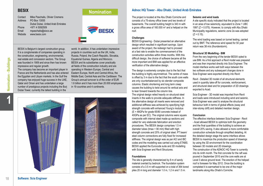
Adnoc HQ Tower - Abu Dhabi, United Arab Emirates
The project is located at the Abu Dhabi Corniche and consists of a 75-storey office tower and two levels of basements. The overall building height is 343 m with a gross office area of 160.000 m2 and a helipad on the roof.
ChallengesBESIX Engineering - Dubai presented an alternative design which resulted in significant savings. Upon award of the project, the redesign had to proceed at a fast rate to enable the commencement of the construction activities within three months. With this difficult design, the choice of software became all the more important and BIM was applied for an effective verification of the alternative design.
The design is extremely complex due to the fact that the building is highly asymmetrical. The centre of mass is offset by 3 m due to the fact that the south core walls are only counterbalanced by six slender composite columns. Elastic shortening and long term creep causes the building to twist around its vertical axis and to lean forward towards the column line.The original design relied heavily on structural steel inserts in the walls to provide adequate stiffness. In the alternative design all inserts were removed and additional stiffness was achieved by specifying high strength concrete with enhanced Young’s modulus (E = 48GPa for grade 65/80 concrete instead of 40GPa as per EC). The original columns were square composite with internal steel made-up sections and called for very elaborate fabrication and erection procedures. The BESIX design comprises 1.5 m diameter tubes (tmax = 90 mm) filled with high strength concrete and 20% of original steel. PT beam/steel column connections are fully fixed for increased stiffness. The original design was as per ACI and IBC codes and the modelling was carried out using ETABS. BESIX applied the Eurocode suite and 3D modelling with Scia Engineer and Revit Structures.
FoundationsThe site is generally characterized by 8 m of sandy material overlaid by bedrock. The foundation system consists of a 3.5 m raft supported on a total of 364 bored piles 20 m long and diameter 1.0 m, 1.2 m and 1.5 m.
Seismic and wind loads A site specific study indicated that the project is located in an area of low seismicity, equivalent to Zone 1 UBC 1997 (Z = 0.075). However, to comply with Abu Dhabi Municipality regulations, seismic zone 2a was adopted (Z = 0.15).
The wind loading was based on tunnel testing, carried out by BMT. The reference wind speed for 50 year return was 38 m/s (thunderstorm).
Structural 3D Modelling - BIMFrom the very beginning of the tender BESIX opted to use BIM. As a first approach a Revit model was prepared and was then imported directly into Scia Engineer. The model interface works well both ways between the two software and any subsequent changes done in Scia Engineer were exported directly into Revit:
Revit - Detailed 3D model of all structural elements used in quantity take-off for concrete, reinforcement, and structural steel and for preparation of 2D drawings exported to Acad.
Scia Engineer - 3D model was imported from Revit and loads were introduced including wind and seismic. Scia Engineer was used to analyse the structural behaviour both in terms of global effects (sway and inter-storey drift) and detailed member design.
ConclusionThe effective interface between Scia Engineer - Revit - Acad allowed BESIX to optimize both the geometry and the final quantities of the building to achieve an overall 20% saving. It also allowed a more comfortable construction schedule through simplified detailing. At the detailed design stage the same interface allows BESIX to maximize the production speed of drawings by using the 3D environment for the coordination between 3D models and 2D drawings.The construction of the ADNOC HQ Tower is currently into its ninth month. The first concrete for the raft was poured in September 2010 and the core walls are at Level 3 above ground level. The erection of the helipad roof is foreseen for May 2012. Once the building is completed it is earmarked to be one of the major landmarks along Abu Dhabi’s Corniche.
BESIX is Belgium’s largest construction group. It is a conglomerate of companies operating in the construction, engineering, environmental, real estate and concession sectors. The Group was founded in 1909 and since then has known impressive and regular growth.The company has become an important player in France and the Netherlands and has also entered the Egyptian and Libyan markets. In the Gulf the company has enjoyed huge success in the UAE, Qatar and Oman and has undertaken a large number of prestigious projects including the Burj Dubai Tower, currently the tallest building in the
world. In addition, it has undertaken impressive projects in countries such as the UK, India, Russia, Poland, the Czech Republic, Slovakia, Equatorial Guinea, Algeria and Morocco.BESIX and its subsidiaries cover practically all fields of the construction industry and are operating in Western Europe, Central and Eastern Europe, North and Central Africa, the Middle East, Central Asia and the Caribbean. The Group’s annual turnover is of the order of EUR 1.6 billion and it has more than 20.000 employees in 19 countries and 4 continents.
BESIX . . . . . . . . . . . . . . . . . . . . . . . . . . . . . . . . . . . . . . . . . . . . . Adnoc HQ Tower - Abu Dhabi, United Arab Emirates
Nomination

19
Project information
Short project description
Nemetschek Engineering User Contest 2011 - Category 1: Buildings
1
Nom
inat
ion
- Bui
ldin
gs
Owner AdnocArchitect HOKGeneral Contractor Six ConstructEngineering Office Halcrow YollesConstruction Period From May 2010 to April 2013Location Abu Dhabi, United Arab Emirates
The Adnoc New Corporate Headquarters is an impressive 343 m tower. When completed in February 2013 it will become the tallest building in the Emirate with a total of 75 storeys and a gross floor area of 160.000 m2. BESIX is responsible for the alternative structural design. The Tower is a rhomboid with an angle of 60°, the height-to-base width ratio is 10 and it is topped - with a 66 m roof bridge and a private helipad. Other main features are the full-height glass façade front and back and the granite cladding along its sides. The front face is supported by slender columns spaced at wide intervals for maximum exposure.
Adnoc HQ TowerAbu Dhabi, United Arab Emirates
BESIX . . . . . . . . . . . . . . . . . . . . . . . . . . . . . . . . . . . . . . . . . . . . . Adnoc HQ Tower - Abu Dhabi, United Arab Emirates

20
1
Nom
inat
ion
- Bui
ldin
gs
Conserela UAB . . . . . . . . . . . . . . . . . . . . . . . . . . . . . . . . . . . . . . Office Blocks Gedimino 35 - Vilnius, Lithuania
Conserela UABContact Arturas Vitkus, Virmantas Juocevicius,
Ricardas PetrikasAddress Žukausko g.17 LT-08234 Vilnius, LithuaniaPhone +370 52788886Email [email protected] www.conserela.lt
Office Blocks Gedimino 35 - Vilnius, Lithuania
Project descriptionThe project is located near the old town of Vilnius. The site consists of three office buildings. Two old buildings are under reconstruction and one is new. The total area of the 3 buildings is 9.860 m2. The new part is about 6.450 m2 and eight storeys high. Three storeys are underground and five above the ground.
Structural system and geometryDue to tight dimensions and difficult geological conditions on the site, the architectural solution is geometrically complex: for example sloping slabs in the parking area eliminating the need of deep digging and a challenging external facade.
It was decided to add a load bearing function to the facade, because the introduction of internal concrete columns at the edge of the office area would lead to compromises in the parking space below, which was already very scarce.
The upper part of the structure consists of:• Reinforced concrete columns 400 x 400 mm• Reinforced concrete walls 250 - 300 mm • Flat slabs 250 mm• External steel facade made of RHS and welded
sections connected through special details eliminating cold bridges.
The underground part of the structure consists of: • Retaining walls made of drilled concrete piles
d450 - 600 mm, with a concrete facing wall• Oval columns 1200 x 500 mm• Reinforced concrete walls 250 - 350 mm• Sloping flat slabs and ramps 300 mm.
Vertical elements of upper and lower parts of the structure are connected by a transfer slab at the ground level. There are 1 meter high transfer beams supporting 5-storey-high columns and a shifted reinforced concrete core. The transfer composite beam system is placed to support the inner steel facade part, which itself acts as a huge truss and which supports the edges of the office slabs.
Software used for this project• Scia Engineer - structural analysis and design
according to Eurocodes
• Bentley Structural - 3D modelling, general arrangement drawings, reinforced concrete detailing
• Allplan - reinforced concrete detailing• Tekla Structures- façade and atria steel
detailing (by FMC Probalt, Lithuanian branch of FinMapConsulting)
Use of Nemetschek productsThe analytical scheme was created in MicroStation and the Scia Engineer ability was used to import 3D DWG files and use them to quickly create structural schemes, detect and fix mistakes made by modelling Scia Engineer proved its efficiency. Also the possibility to handle such a difficult geometry and the ability to use layers to separate structural elements were perfect in the FEM program.
The main structural scheme enabled our team to assess forces for steel and transfer structures design. The steel structure was checked according to EC3 with Scia Engineer and also by the Steel Detailing Engineer with Excel spreadsheet calculations. Forces for member and connection design with Excel were exported from a Scia Engineer file to a 3D DWG and 3D PDF files which proved to be very easy to use and more preferred by engineers than tabulated data. In this project “Conserela” prepared and checked more than 20 analytical schemes at different design phases and analysis levels including main structural schemes, several detailed parts like transfer structures with part of façade, each floor slab, transfer beams, stairs, walls, the atrium structure etc.
Allplan was also used in this project. The reinforcement of RC structural walls involving complex geometries has been designed with the aid of the Allplan reinforcement module. It helped to reduce the amount of errors and track changes in the wall geometry. Some details were provided to the construction site as 3D pdf files for better understanding of critical places. It was extremely helpful to automatically produce the part lists of the reinforcement elements instead of performing manual calculations.
Conserela Ltd - the company name stands for “construction related services”.
Conserela Ltd was founded in 2007 in Lithuania.
The company employs skilled project-management and design professionals and provides services as a “Design and Build” Company, project management, general contractor, technical supervisor, financial controller, investor adviser and or design firm.
The CEO and the key persons of Conserela Ltd come from one the biggest Lithuanian
construction companies. They contributed to the company by their experience and ability to manage effectively “design and build” contracts, which they gained during the 12 years of practice as key members in an international project team.
Software: Allplan Engineering, Scia Engineer
Nomination

21
Project information
Short project description
Nemetschek Engineering User Contest 2011 - Category 1: Buildings
1
Nom
inat
ion
- Bui
ldin
gs
Office Blocks Gedimino 35Vilnius, Lithuania
Conserela UAB . . . . . . . . . . . . . . . . . . . . . . . . . . . . . . . . . . . . . . Office Blocks Gedimino 35 - Vilnius, Lithuania
Owner SomeneraArchitect Hackel-Kaape, Trimonis & CoGeneral Contractor LakajaEngineering Office ConserelaConstruction Period From July 2009 to May 2011Location Vilnius, Lithuania
The office complex Gedimino 35 consists of three building structures. Two old reconstructed buildings and one new building. “Conserela” is responsible for the structural design of the new part. The new part has three underground storeys and 5 levels above. The main structural system is a cast in situ concrete frame with flat slabs, reinforced concrete columns, walls and an external load bearing steel facade designed of RHS and welded sections. The facade is connected to the slab trough special details to eliminate cold bridges. The foundation of the structure consists of drilled cast in situ piles, pile caps, mats and retaining walls.

22
1
Nom
inat
ion
- Bui
ldin
gs
Software: Scia Engineer
St Mary of the Angels Primary School - London, United Kingdom
The project is situated on Shrewsbury Road adjacent to Westbourne Park Road in the Bayswater area of London W2. The site is rectangular in shape with the new building taking up half of the site.The school is a three-storeyed ‘kidney shape’ building with external staircase and ramp. Other parts of the site are taken up by play areas. Thomasons input on this project comprised the full civil and structural design.
Description of the projectEach floor of the building steps over involving a number of cantilevered areas. The architectural arrangement involved relatively free internal spaces. Due to these issues, as well as the curved plan profile of the building, a concrete frame was chosen.The building structure consists of RC slabs (350 mm - 450 mm deep) supported on RC walls/columns. Except for the lift walls, there is no continuous line of structural support. A staircase wraps around the lift shaft and is therefore not providing any support to the floor slab. Due to the irregular shape of the building, the concentration of loads and soil conditions, piled foundations were chosen.
The external staircase has been designed as a curved RC structure supported on RC columns due to the shape.The stability calculations formed a big challenge as there were no continuous vertical walls. The frame action of the structure has been taken into account to provide lateral stability. One of difficulties in design were the existing retaining walls, running along the street and pavements, because of which the ground floor slab had to be cantilevered over piles with positions determined by retaining walls bases.
ApproachThere were many challenges when undertaking the design of the building. They comprise of the following:• The whole main structure of the building has been
modelled in one Scia Engineer file to get reactions on piles. The reason for this is that each floor acted as a transfer slab with a different location of support and therefore without modelling the whole structure. The results could not be predicted.
• Scia Engineer software allowed the long term deflection and stresses to be obtained.
• Analysis of slabs. Taking into account large openings. Openings were undertaken to ensure correct reinforcement requirements.
• Lateral stability of the building has been analysed taking frame action into account as there were no continuous shear walls.
• The spiral staircase around the lift core was detailed based on results from Scia Engineer. Especially useful was in this case the Scia Engineer option of main stresses and forces trajectories preview.
• RC ramp has been designed .
The use of Scia EngineerScia Engineer was very useful, as we were able to analyse different structural solutions and advise to the architect the best economical solution which allowed the interesting shape of building and visual effect to be achieved.
Visualisation of results: maps, values, trajectories helped us to get the most economical structural solution.
Thomasons was founded in 1947 and is now one of the most established independently owned consulting engineering firms in the UK.
The firm has established a deserved reputation for engineering excellence, innovation and a high quality of customer service, a process that is measured year by year in our customer surveys. The firm and its associated companies currently operate from regional offices in Guildford, London, Leeds, Manchester, Birmingham and Southend-on-Sea with approximately 135 staff. We work throughout the UK and have also
undertaken projects internationally in areas including Ireland, France and the Channel Islands.
Thomasons undertakes commissions in all areas of civil and structural engineering including major healthcare, education, residential, retail and mixed use town centre redevelopments.
An ISO9001 Quality Management System is operated in all offices and externally audited by a UKAS accredited assessment body.
Thomasons . . . . . . . . . . . . . . . . . . . . . . . . . . . . . . . . . . . . . . . . . St Mary of the Angels Primary School - London, United Kingdom
ThomasonsContact Krzysztof SkwarekAddress 528 High Road E11 3EE London, United KingdomPhone +44 2089885820Email [email protected] www.thomasons.co.uk
Nomination

23
Project information
Short project description
Nemetschek Engineering User Contest 2011 - Category 1: Buildings
1
Nom
inat
ion
- Bui
ldin
gs
Owner Westminster City CouncilArchitect Ingleton WoodGeneral Contractor Speller MetcalfeEngineering Office Thomasons (London)Construction Period From December 2009 to October 2010Location London, United Kingdom
This project is about the St Mary of the Angels Primary School, situated on Shrewsbury Road adjacent to Westbourne Park Road in the Bayswater area of London W2. The three-storeyed ‘kidney’ shaped building, with cantilevered slabs on each level, has been designed as a reinforced concrete frame structure and full FEM analysis was undertaken. Using Scia Engineer software let us connect the required architectural visual effect with the most economical building solution.
St Mary of the Angels Primary SchoolLondon, United Kingdom
Thomasons . . . . . . . . . . . . . . . . . . . . . . . . . . . . . . . . . . . . . . . . . St Mary of the Angels Primary School - London, United Kingdom

24
1
Cate
gory
1: B
uild
ings
Adams Bouwadviesbureau bv . . . . . . . . . . . . . . . . . . . . . . . . . . . Five Flats and Shop-Premises - Druten, The Netherlands
Software: Allplan Engineering, Scia Engineer
Adams Bouwadviesbureau bvContact Paul BierAddress Van Heemstraweg 123f 6651 KH Druten, The NetherlandsPhone +31 487 588280Email [email protected] www.adamsbouwadvies.nl
Vijf Appartementen en Winkelruimte - Druten, Nederland
BIM is één van de nieuwste ontwikkelingen op het gebied van gegevens uitwisselen in de bouw. Een partij zet een model op en een andere partij voegt hier zijn gegevens aan toe. De uitwisseling via het internet is een stuk sneller en goedkoper dan de stukken via de post versturen. Voorheen was de kans op afstemmingsproblemen aanwezig doordat tekeningen van diverse partijen met elkaar vergeleken moesten worden en hier dingen over het hoofd gezien konden worden. Daarbij werd er naast het bouwkundig model, ook een constructief model opgezet; dubbel werk dus! Bij ons is het idee geboren om een bouwkundige en constructieve tekening te genereren uit één 3D-model. We hebben een intern BIM-systeem ontwikkeld binnen Allplan, waarbij we met één druk op de knop kunnen schakelen tussen een bouwkundige naar een constructieve tekening en omgekeerd. Alle aanpassingen die wij maken in de bouwkundige of constructieve tekening worden overgenomen in de andere discipline. Afstemmingsproblemen behoren hierbij tot het verleden en er wordt geen tweede model opgesteld voor de constructieve tekening.
Opzet 3D-modelDe moeilijkheid schuilt in het combineren van de twee disciplines. Een bouwkundige tekening heeft bij ons andere arceerpatronen en pendikten dan een constructieve tekening. Daarbij zijn er onderdelen van een bouwkundige tekening die je niet wilt zien op een constructieve tekening en omgekeerd. Daarbij zijn er ook onderdelen die beide disciplines gebruiken of gedeeltelijk gebruiken zoals een sparing met kozijn.In het 3D-model hebben we onderscheid gemaakt tussen bouwkundige en constructieve elementen. We hebben bij de gecombineerde elementen een schakeling aangebracht die pendikte en arcering veranderen door te switchen tussen disciplines. Sommige elementen, zoals buitengevel en isolatie, worden hiermee op hulpconstructie gezet. Andere elementen veranderen van dikte en arceerpatroon. Het aanpassen van tekeningen wordt een stuk efficiënter, doordat beide disciplines gebruik maken van hetzelfde architectuurelement. Wanneer een kozijn groter gemaakt wordt of verplaatst wordt, zal Allplan beide tekeningen in één handeling aanpassen. Alle gekoppelde elementen aan de wand, zoals kozijn,
sparing, macro’s, sponningen, etc. worden aangepast. De maatvoering van de sparingen en kozijnen zal wel aangepast moeten worden, omdat deze op een andere laag staat. Voor de indeling van de appartementen hebben we gebruik gemaakt van Xrefs. Alle appartementen hebben dezelfde indeling waardoor ze doorgekopieerd kunnen worden in Xref-vorm. Wordt de indeling veranderd dan hoeft er maar één plattegrond aangepast te worden. Allplan verricht het repeterende werk.
Gegevens uit het 3D-model halenDoordat alle onderdelen met architectuurelementen zijn getekend, kunnen we uit al deze elementen informatie halen. Elk onderdeel heeft een materiaal toegekend gekregen waardoor deze zichtbaar wordt in, bijvoorbeeld, een lijst. Deze lijsten kunnen als basis dienen voor calculatie of inkoop voor de opdrachtgever of aannemer. Naast de lijsten kunnen we door middel van attributen, interactieve teksten, gebruik maken van de architectuurelementen. Gegevens zoals hoogte, dikte, lengte, afstand ten opzichte van het peil, vierkante meters, kubieke meters, materiaal, etc. kunnen uit de gegevens worden gehaald. In principe hoeft alleen het 3D-model aangepast te worden en alle attributen worden automatisch gewijzigd. Ook hier wordt tijd bespaard en de kans op fouten verkleind.
Meer gebruik maken van het 3D-modelHet gebruik van een 3D-model biedt naast beter inzicht in aansluitingen en het uitdraaien van hoeveelheden ook de mogelijkheid om handelingen te vergemakkelijken en te versnellen. Zo hebben we in dit model alle gevels en doorsneden gegenereerd uit het 3D-model. Voor de gevels hebben we een schaduwberekening gemaakt en deze gebruikt in de geveltekening, wat normaal gesproken een bewerkelijke klus is; helemaal bij een complex gebouw.
ConclusieDoor het 3D-model slim te gebruiken, wordt een hoop tijd bespaard. Door in de beginfase van het proces meer tijd te spenderen aan het zo compleet mogelijk maken van het model, wordt uiteindelijk tijd gewonnen én efficiënter gewerkt.
Adams Bouwadviesbureau bv is een raadgevend ingenieursbureau op het gebied van draagconstructie en bouwkunde. Veiligheid, innovatie en kwaliteit staan hoog in het vaandel. Onze uitgebreide ervaring ligt op het terrein van woning- en utiliteitsbouw, uiteenlopend van individuele projecten tot grootschalige stadsvernieuwing. Sinds de oprichting in 1995 is het bureau gegroeid tot een bedrijf van 18 medewerkers met de flexibiliteit van een klein bedrijf en het kennisniveau van een grote organisatie.Zelf ontwikkelde rekenprogramma’s en software
van Scia ondersteunen het rekenwerk. Hiermee worden alle twee- en driedimensionale staaf-, plaat- en schijfconstructies berekend.Al het tekenwerk wordt uitgewerkt met Allplan. De driedimensionale modellen gebruiken wij om conflicten te verduidelijken aan betrokken partijen en om particulieren het ontwerp te verduidelijken. Het dienstenpakket van Adams Bouwadviesbureau bv bestaat uit constructieve en bouwkundige advisering in opdracht van opdrachtgevers zoals, woningbouwcoöperaties, projectontwikkelaars en architecten.

25
Project information
Short project description
Nemetschek Engineering User Contest 2011 - Category 1: Buildings
Cate
gory
1: B
uild
ings
1
Adams Bouwadviesbureau bv . . . . . . . . . . . . . . . . . . . . . . . . . . . Five Flats and Shop-Premises - Druten, The Netherlands
Five Flats and Shop PremisesDruten, The Netherlands
Owner Koperen Droes bvArchitect Adams Bouwadviesbureau bvEngineering Office Adams Bouwadviesbureau bvConstruction Period From 2008 to ...Location Druten, The Netherlands
In this project we have saved a lot of time by making clever use of Allplan. From a 3D model we generated two drawings, a constructive and an architectural drawing. Any changes we make in one of the disciplines are automatically modified in the other discipline. This saves time and reduces the risk of errors. With one click we can switch between an architectural and constructive view. This is, in fact, an internal BIM. We are also able to model all the quantities into a list which, for example, can be used for calculation.

26
1
Cate
gory
1: B
uild
ings
Adviesburo de KwaadstenietContact Jaap de Kwaadsteniet, Frans Cox, Noël KöhneAddress Europalaan 40 5531BH Bladel, The NetherlandsPhone +31 497381218Email [email protected] www.kwaadsteniet.info
Software: Allplan Engineering, Scia Engineer
Showroom Habufa - Hapert, Nederland
Allplan en Scia Engineer bij de Adviesburo J.H. de KwaadstenietDe uitgebreide mogelijkheden en daarbij toch de eenvoud van modeleren in 3D, heeft Adviesburo J.H. de Kwaadsteniet BV in 2003 doen besluiten over te stappen naar Allplan. Door het 3D-concept wordt slechts één model bijgewerkt en volgen de wijzigingen in de afgeleide aanzichten.
Deze mogelijkheden zijn belangrijk voor een volledige integratie van het gehele bouwproces voor zowel staal- als betonconstructies, en voor het voorkomen van fouten.
De voordelen van het werken met Allplan wekte vervolgens de interesse voor het gebruik van Allplan in combinatie met Scia Engineer. Deze combinatie van programma’s biedt de mogelijkheid om het rekenen en tekenen in één model te integreren. Dit maakt het voor Adviesburo J.H. de Kwaadsteniet BV mogelijk te komen tot een volledige integratie van alle facetten van het bouwproject.
HabufaGezien het complexe karakter van het ontwerp voor de nieuwbouw van een showroom voor meubelbedrijf Habufa in Hapert (ontwerp door Van der Sande Architecten te Bladel) is gekozen dit project te tekenen in Allplan en met behulp van Scia Engineer te berekenen.
Het bouwkundig ontwerp met een constructieve uitstraling is daartoe eerst vertaald middels het 3D uitwerken van de constructie in Allplan.
De benodigde dimensies van de verschillende bouwelementen (stalen balken en kolommen, betonwanden, kanaalplaatvloeren etc.) zijn daarbij door de constructeur voorlopig bepaald, als conceptontwerp.
Nadat het 3D-model is afgerond, wordt het model overgezet naar Scia Engineer om daar de constructieve samenhang te controleren. Na opgave van alle belastingen in het Scia Engineer model wordt gecontroleerd of de eerder bepaalde dimensies correct zijn en waar nodig worden deze aangepast. Tevens zijn de afmetingen van de fundering en benodigde wapening van de betononderdelen bepaald aan de
hand van de reactiekrachten die uit het rekenmodel volgen.
Al met al een efficiënte werkwijze om de krachten van de tekenaar en de constructeur te bundelen, waarbij het model maar éénmaal uitgewerkt dient te worden, en niet ieder afzonderlijk zijn eigen model uitwerkt.
Wat brengt de toekomst?De nieuw opgedane werkervaring in combinatie met tips van de software ontwikkelaar leiden naar een meer doordachte en doeltreffendere werkwijze. Belangrijk blijft de visualisatie van alle bouwelementen, zoals stalen balken en kolommen, betonwanden en kanaalplaatvloeren om de controles op de samenhang uit te kunnen voeren.
De rekensoftware Scia Engineer wordt steeds vaker ingeschakeld voor het berekenen van betonelementen, maar ook als modeller van staal in 3D.
De producten van Nemetschek Scia maken het nu en in de toekomst nog beter mogelijk om het bouwproces efficiënt en voorspelbaar te laten verlopen. Ook de luisterbereidheid van de software-ontwikkelaar naar de noden en wensen van de klant, maakt dat deze software hét instrument is en blijft om vooruitgang te boeken en tevredenheid te behouden.
Adviesburo J.H. de Kwaadsteniet BV is een onafhankelijk raadgevend ingenieursbedrijf dat werkt aan integrale oplossingen op het gebied van bouwconstructies. De hoofdactiviteit is het constructief ontwerpen van draagconstructies in de woning- en utiliteitsbouw. Het bureau ontwerpt voornamelijk kantoorgebouwen, appartementen én bedrijfshallen en dit zowel in staal, beton als beide gecombineerd. Het bureau streeft naar een betere integratie van alle facetten van het bouwproject om klanten, vanaf ontwerp tot en met de bouwbegeleiding, in volledige mate bij te staan.
Snelheid, vooruitdenken en flexibiliteit typeren deze aanpak. Door complexe vraagstukken vanuit een brede invalshoek te bekijken en tevens het reken- en tekenproces als één doorlopende procedure te beschouwen, worden efficiënte oplossingen geboden. Betrouwbaar en praktisch uitvoerbaar zijn daarbij de kernwoorden.Aan het begin van 2011 zijn de werkzaamheden van Adviesburo J.H. de Kwaadsteniet BV overgegaan in CK2 (Cox-Köhne-De Kwaadsteniet), het personeelsbestand is echter ongewijzigd gebleven.
Adviesburo de Kwaadsteniet . . . . . . . . . . . . . . . . . . . . . . . . . . . . Showroom Habufa - Hapert, The Netherlands

27
Project information
Short project description
Nemetschek Engineering User Contest 2011 - Category 1: Buildings
Cate
gory
1: B
uild
ings
1
Owner Habufa MeubelenArchitect Van der Sande ArchitectenGeneral Contractor Bouwbedrijf Rooijakkers BVEngineering Office Adviesburo J.H. de KwaadstenietConstruction Period From 2011 to 2012Location Hapert, The Netherlands
Showroom HabufaHapert, The Netherlands
The project is about the complex design for the construction of a showroom; the model has been drawn in Allplan and the calculation is done by Scia Engineer. The architectural design is translated into a construction model in Allplan. Dimensions of various components are specified. After completion, the construction model is transferred to Scia Engineer for an internal check of the structural design. After input of the various loads in the Scia Engineer model, the dimensions are verified and adjusted. It is an efficient method to combine the skills of draftsmen and engineers and the construction model has to be designed and drawn only once.
Adviesburo de Kwaadsteniet . . . . . . . . . . . . . . . . . . . . . . . . . . . . Showroom Habufa - Hapert, The Netherlands

28
1
Cate
gory
1: B
uild
ings
Software: Scia Engineer
AECOM . . . . . . . . . . . . . . . . . . . . . . . . . . . . . . . . . . . . . . . . . . . . Heartlands High School - London, United Kingdom
Heartlands High School - London, United Kingdom
Heartlands High School is a new build secondaryschool in Haringey, London and will receive about1.100 students. It is situated on an old railway yard adjacent to the East Coast Mainline railway. The long, narrow site runs alongside the railway lines and slopes down approximately 7 - 10 m over its width.
A sheet piled retaining wall was installed through the middle of the site to create an upper level next to the railway lines and a lower level (set 7 m down) to match the surrounding ground level at the bottom of the old embankment. The new school comprises of a 3 storey structure at the higher level with two 5 storey “wing” buildings sitting at the lower level which tie into the upper building at third floor.
Key structural design features• Analysis for ground-borne vibration due to close
proximity of passing trains• Steeply sloping site
FoundationsDisplacement piled foundations and a suspended concrete slab were used due to the relatively poor ground conditions on the site.
Structural frameThe structural form for the majority of the building is an in situ reinforced concrete flat slab supported by concrete columns and stabilized by concrete shear walls.
At areas requiring large clear spans (such as sports and performance halls) the structure changes to a steel frame.
Design for rail vibrationHeartlands High School is situated adjacent to the very heavily used East Coast Mainline Railway. Concerns over the level of ground-borne vibration due to passing trains led to a program of monitoring and analysis to verify the design.
The school required the building to limit the vibration experienced by the users to a specific vibration dose value. At the beginning of the project the concern was that the level of vibration being created by the trains
may require the building to be set on spring bearings to isolate the structure from the ground in order to achieve the required dose value. This would have been extremely costly and hence we were commissioned with the task of analysing the building to see if we could achieve the required vibration dose value by considered design of the concrete structure.
Vibration acceleration spectra generated by passing trains were recorded via a test pile installed at the site. The spectra were then input into Scia Engineer as seismic loads using the advanced dynamics module.
Scia Engineer’s contour plot of the summation of vibration acceleration in all modes was used to determine critical zones for detailed analysis. Raw accelerations for each mode of vibration at the critical node were exported to a series of spreadsheets for summation in frequency-weighted 1/3-octave bands. The key challenge of this project was to generate the right amount of data. Exporting spreadsheets containing acceleration data for every node and every mode would have overwhelmed most computers. Instead, sub-regions of the slab were used to target specific areas for data export. The final stage of calculation using these spreadsheets was to combine the predicted floor vibration levels into a ‘vibration dose value’ (VDV), which is a measure of vibration used in the UK that takes into account both the intensity and duration of vibration.
AECOM used this methodology to consider the effect of various design iterations including additional rows of columns within critical spans. AECOM’s in-depth analysis gave the contractor confidence that the design would achieve the stringent vibration criteria without the need for spring bearings.
AECOM is a global provider of professional, technical and management support services to a broad range of construction and infrastructure markets.
With approximately 51.000 employees around the world, AECOM is a leader in all of the key markets that it serves, providing a blend of global reach, local knowledge, innovation and technical excellence in delivering solutions that enhance and sustain the world’s built, natural, and social environments.
From major road and rail projects to energy generation, water management systems and creating beautiful and successful buildings and places, AECOM in Europe works closely with clients across all areas of the built and natural environment.
Our teams of award-winning engineers, designers, planners and project managers ensure that our solutions outperform convention. Combining global resources with local expertise provides exceptional, high-quality, cost-effective professional and technical solutions.
AECOMContact Gemma Clarke, Tom LeeAddress 63-77 Victoria Street AL1 3ER St Albans, United KingdomPhone +44 1727535000Email [email protected] www.aecom.com

29
Project information
Short project description
Nemetschek Engineering User Contest 2011 - Category 1: Buildings
Cate
gory
1: B
uild
ings
1
Owner Haringey CouncilArchitect HMYGeneral Contractor Willmott DixonEngineering Office AECOMConstruction Period From September 2009 to April 2011Location London, United Kingdom
Heartlands High SchoolLondon, United Kingdom
AECOM . . . . . . . . . . . . . . . . . . . . . . . . . . . . . . . . . . . . . . . . . . . . Heartlands High School - London, United Kingdom
Heartlands High school is a newly build school in Haringey, London and will receive about 1.100 students. The building is situated on an old railway yard, adjacent to the very heavily used East Coast Railway. Concerns over the level of ground-borne vibration due to passing trains led to a program of monitoring and analysis to verify the design of the concrete flat slab structures to limit the vibration experienced by the users to a specific vibration dose value. The analysis was carried out using the Scia Engineer dynamics module by imputing acceleration spectra generated by passing trains as seismic loads.

30
1
Cate
gory
1: B
uild
ings
BARAN PROJEKT s.r.o.Contact Jozef BaranAddress Tomášikova 3/A 82101 Bratislava, Slovak RepublicPhone +421 2 43411703Email [email protected] www.baranprojekt.sk
Mirage Shopping Centre - Zilina, Slovak Republic
Description of the projectThe building is designed as a reinforced concrete monolithic skeleton structure with bracing walls. It consists of two main parts - four-floor bodywork of the existing park house and the new building with eight floors (four underground floors).The foundation slab of the new building has a thickness of 800 mm and is laid on the clay stone layer 1.5 m under the underground water level.
The foundation slab and the peripheral underground walls are made of watertight reinforced concrete. The vertical load-bearing elements are reinforced concrete monolithic columns and walls.
The walls of the vertical communication cores ensure the stability of the building.
The spans in the main elliptic axis are 10.5 m. There is a primary continuous beam placed on these columns as well as on the secondary conic beams anchored to it and taking the cantilever of 4.2 m.
The cantilever circles around the whole interior space. In the third floor there is a main elliptic beam placed on
the end of the cantilever performing as a support for the great glass dome skylight.
The span of the skylight is 32 m. Horizontal load-bearing elements are beamless solid slabs with reinforced concrete mushroom heads.
The thickness of the slabs is 220 mm and the mushroom heads ensure that the allowed deflections and shear forces are not exceeded.
The existing park house was executed with the possibility of the bodywork for four uniform floors. New architectural design requested different modulus axis. That is why the new massive reinforced concrete grid was designed at that spot, taking the columns of the upper part. Some vertical load-bearing elements of the existing park house had to be strengthened. Here were added the micro piles working together with the existing foundation slab at positions where the pressure in the foundation base was too high.
The use of Scia Engineer softwareThe software Scia Engineer was used for the static and dynamic analysis. The Slovak standards were used for the calculation.
Two complete models of the structure were made and all load-bearing elements were designed.
Scia Engineer allowed to model the complicated building very easily. It allowed for the preparation of several alternatives of the structure as well. There were more designs in the process of the work according to client’s and architect’s demands and Scia Engineer made it possible to change the structure very easily.
The real deflections of the structure were measured on site, and the results are very near to the calculated deflections.
BARAN PROJEKT s.r.o. was established in May 2006 as a continuation of already elaborated projects of its founder Jozef Baran. After his graduation at the Slovak University of technology in Bratislava in 1976 he started to work as a structural engineer at the state-owned company SPTU, one of the biggest design engineering companies in Slovakia. After the change of the political system in 1990 he passed the examination of a professional qualification, obtained the authorised certificate from the Slovak Chamber of Civil Engineers and in accordance with the new laws he started to work
as a structural engineer - entrepreneur. This work - complex project documentation in the field of structural engineering, static and dynamic analysis as well as the expertises - he has been doing since his graduation.
Some of the many projects that he has worked on as a lead structural engineer can be seen on the website www.baranprojekt.sk.
Software: Scia Engineer
BARAN PROJEKT s.r.o. . . . . . . . . . . . . . . . . . . . . . . . . . . . . . . . Mirage Shopping Center - Zilina, Slovak Republic

31
Project information
Short project description
Nemetschek Engineering User Contest 2011 - Category 1: Buildings
Cate
gory
1: B
uild
ings
1
Owner Mirage Shoping Center a.s.Architect Michal Divis Architekti s.r.o., Zilina, Slovak RepublicGeneral Contractor Ekostav Slovak Republic s.r.o.Engineering Office Michal Divis Architekti s.r.o., Zilina, Slovak RepublicConstruction Period From January 2009 to November 2010Location Zilina, Slovak Republic
The project is about the Mirage Shopping Centre of Zilina. Citizens and visitors can enjoy a walk across the covered square, do some shopping in numerous shops offering world-renowned brands and utilise many top-class services. The Mirage Shopping Centre features 4 cinemas, many restaurants, pubs, the town’s largest children’s corner, bowling and other sport facilities. Mirage offers a high-capacity underground car-park. Unique are the cascading floors with barrier-free access, dominated by a glass dome skylight in the building roof enhancing the feeling that the visitor is actually on a square in open air.
Mirage Shopping CenterZilina, Slovak Republic
BARAN PROJEKT s.r.o. . . . . . . . . . . . . . . . . . . . . . . . . . . . . . . . Mirage Shopping Center - Zilina, Slovak Republic

32
1
Cate
gory
1: B
uild
ings
BG Ingénieurs ConseilsContact Lynn LecorsaisAddress Avenue de Cour, 61 1007 Lausanne, SwitzerlandPhone +41 21 618 11 11Email [email protected] www.bg-21.com
Villa-les-bains - Montreux, Switzerland
The idea for this high-specification building on the shores of Lake Geneva came about in 2005. Following the granting of planning permission in 2007, the project was left on hold for two years, and ground-works weren’t started until March 2009, with the completion of building shell and core expected in early 2011.
Project description This multi-use building on the lake shore is squeezed into a tight site with an irregular geometry. The lower floors are surrounded by the famous Montreux Casino, a villa dating from 1900, the promenades along the lake shore and a road.
The building is split into a north zone and a south zone, linked by a 2.460 m2 private car park. In the north zone the podium is completed by a second level of car park as well as two levels above-ground (commercial and residential) above which rise two nine-storeyd towers. In the south zone two smaller towers, each of five storeys, rise above the underground car park.
The area for commercial use is 430 m2 and the 33 high-specification apartments each have areas of between 160 and 200 m2.
Structural concept Various problems were encountered during the design of this project. The site constraints (complex geometry, surrounding buildings, and basement slab at lake level) required the use of various geotechnical works for both permanent and temporary works, including bored piles, king post walls, ground anchors, underpinning, and mini-piles.
The superstructure design is particularly complicated for the following reasons: • Slender structural elements (18 - 20 cm wall
thicknesses, 23 cm slabs spanning 9 m x 7 m)• Interaction of elements with varying stiffnesses• Seismic stability - Montreux is located in the seismic
zone 2 (medium risk) according to SIA, the Swiss design codes
• Few vertical elements• Discontinuity of vertical elements - the load-bearing
tower facades, off-set from the podium walls and columns, are supported on a series of 24 down-stand
transfer beams. This transition level allows the load transfer from the tower facades through to a different structural geometry in the podium.
The consequence is a high reinforcement density, demanding the use of self-compacting concrete and a mixture of solutions in reinforced concrete, composite steel-concrete and post-tensioning.
The static model used has been validated by on site measurements of the transfer beam deflections.
The use of Scia EngineerBuilding on our experience over many years, the 3D program Scia Engineer was crucial for the design and construction of this project.
In particular, the offset in the vertical structure of the towers and the four levels of the podium in the north zone, as well as the influence of element stiffness, would be impossible to resolve in 2D.
We established several models. The complete model, encompassing the north and south towers, gave a global vision of the project and its complexity.
Separate models were then created to study the north and south buildings independently, aiming to reduce both the size of the model and the processing time.
We studied the behaviour of the buildings under seismic loadings both using the response spectrum method and also the replacement force method. The latter was used for the final calculations.
The walls and slabs comprised shell elements, and we made use of the program’s automatic reinforcement design.
Scia Engineer is very useful for structures of this level of complexity, in particular by:• Easily spotting delicate areas• Reducing design time• Keeping a global vision of a complex load take-down • Helping to calculate bracing requirements.
With a 2D program it would not have been possible to design this project.
The BG group…… is a firm of consulting engineers operating on an international level whose objective is to help its clients build a sustainable living environment. United around strong corporate values, BG staff represents a remarkable collective intelligence able to provide simple answers to the complex issues arising from our planet’s development.
Services providedThe 500 strong staff provides extensive services in the fields of infrastructure, environment as well as buildings and energy. BG’s excellence is
renowned in developing complex and challenging multidisciplinary projects, where its in-house competence in project management, risk assessment and optimum use of resources is a decisive factor.
Operating as a general contractor, BG takes responsibility for all engineering services - from the initial analysis of project requirements through to commissioning - including all aspects of project design and implementation.
Software: Scia Engineer
BG Ingénieurs Conseils. . . . . . . . . . . . . . . . . . . . . . . . . . . . . . . . Villa-les-bains - Montreux, Switzerland

33
Project information
Short project description
Nemetschek Engineering User Contest 2011 - Category 1: Buildings
Cate
gory
1: B
uild
ings
1
Villa-les-bainsMontreux, Switzerland
This project concerns a multipurpose, high-specification building, hemmed in by buildings on both sides and the shore of Lake Geneva to the south. It is separated into 2 zones, connected by a private car park, covering 2.460 m2. In the north zone, the podium is completed by a 2 second car park level and 2 floors aboveground, on which two 9-storeyed towers are built. In the south zone, the single storey car park is situated below two 5-storeyed towers. The total usable surface area is 12.600 m2. The design of this building has overcome the constraints of a difficult site, and also a complex, non-orthogonal geometry with many load transfers.
Owner De Rham SA - Nurestra SAArchitect BPF Architectes et Associés SA and Atelier d’architecture Jaunin SAGeneral Contractor Dentan Frères SAEngineering Office Consortium BG Ingénieurs Conseils and Daniel Willi SAConstruction Period From March 2009 to March 2011Location Montreux, Switzerland
BG Ingénieurs Conseils. . . . . . . . . . . . . . . . . . . . . . . . . . . . . . . . Villa-les-bains - Montreux, Switzerland

34
1
Cate
gory
1: B
uild
ings
Bureau d’Etudes ADAM. . . . . . . . . . . . . . . . . . . . . . . . . . . . . . . . Naïade Tornacum - Tournai, Belgium
Bureau d’Etudes ADAMContact Patrick AdamAddress Rue Saint Jean, 9 7500 Tournai, BelgiumPhone +32 69840302Email [email protected] www.patrickadam.be
Naïade Tornacum - Tournai, Belgique
Un bâtiment en plein cœur de la ville de TournaiCe bâtiment datant de 1970 est situé à l’angle de trois axes, à la butée d’un pont et le long de l’Escaut, en plein cœur de la ville de Tournai.
Il est caractérisé par la grande différence de hauteur entre ses différents accès, ainsi que par sa structure poteaux-poutres en béton.
L’ensemble du bâtiment existant est fondé sur des pieux, le sol correspondant en effet à l’ancien lit de l’Escaut. Aucun plan de structure n’a pu être retrouvé, mais la présence de bâtiments mitoyens plus anciens nous font soupçonner des reprises de charges à l’aide de poutres de fondation en porte-à-faux. Ceci nous a amené à une certaine prudence, notamment en limitant les surcharges au niveau des bâtiments mitoyens.
Rehaussement du bâtimentL’ajout de deux niveaux d’habitation en toiture remplace la “fausse toiture” existante qui fut imposée alors par l’urbanisme. Ces nouvelles surfaces habitables impliquent une structure légère, posant uniquement sur les poteaux existants. Cette contrainte ajoutée aux
demandes de l’architecte nous ont amenés à la solution présentée ci-contre.
Une donnée importante qui nous a été imposée est la présence continue de personnel dans les bureaux des étages inférieurs, ce qui implique une intervention délicate par l’extérieur uniquement.
AccèsLe placement d’une nouvelle trémie d’ascenseur a été indispensable à la distribution des appartements créés, et le percement des dalles existantes à chaque niveau a nécessité des renforts structurels.
L’accès pompiers qui nous a été imposé a donné la forme de toiture plate du côté intérieur au L, ainsi que les potelets créant un décalage avec le poteau inférieur de notre structure.
Modèle de calculL’analyse du portique hyperstatique d’une portée totale de 13 mètres a été réalisée premièrement en 2 dimensions. Ceci a permis une optimisation rapide de ce portique par Scia Engineer. L’extrapolation en un modèle 3D s’est vite avérée indispensable afin de tenir compte de l’ensemble de l’ossature dans les reprises des charges de vent, notamment. L’optimisation en 3D a pu alors être lancée.
Le modèle de structure de Scia Engineer nous a donné une visualisation en 3 dimensions du coin, ce qui nous a permis d’adapter notre structure à la demande de l’architecte.
La possibilité de réaliser facilement un fichier PDF-3D, lisible par tout ordinateur, est pour cela très appréciable.
Les appuis sur la structure existante sont réalisés en rotules simples afin de ne solliciter celle-ci qu’en compression, à l’exception des efforts de vent.
La note de calcul a pu être réalisée assez simplement au sein même du logiciel Scia Engineer, et a eu pour avantage de s’adapter automatiquement aux immanquables changements qui sont survenus en cours d’étude.
Le Bureau d’Etudes Patrick ADAM est spécialisé dans le domaine de la stabilité et de la thermique.Armés d’outils informatiques puissants et souples - principalement Nemetschek Scia - nous mettons notre maîtrise technique à votre service, et vous garantissons un suivi rigoureux du projet et du chantier, en mettant un point d’honneur à établir une parfaite collaboration avec l’architecte.En maison individuelle comme pour les bâtiments industriels, en passant par les immeubles et le génie civil, notre bureau vous apporte son savoir-faire dans la résolution de vos problèmes techniques, tant en France qu’en Belgique.
Stabilité:• Calculs de fondations, structures en béton
armé, charpentes métalliques, ossatures bois, etc.
• Modélisation 3D de stations d’épuration
Thermique:• Auditeur énergétique Responsable PEB,
Certificateur PEB• Calculs de maisons passives, dont les études
du premier éco-quartier passif de Belgique: “36°8” à Tournai. (http://www.36-8.be)
Software: Scia Engineer
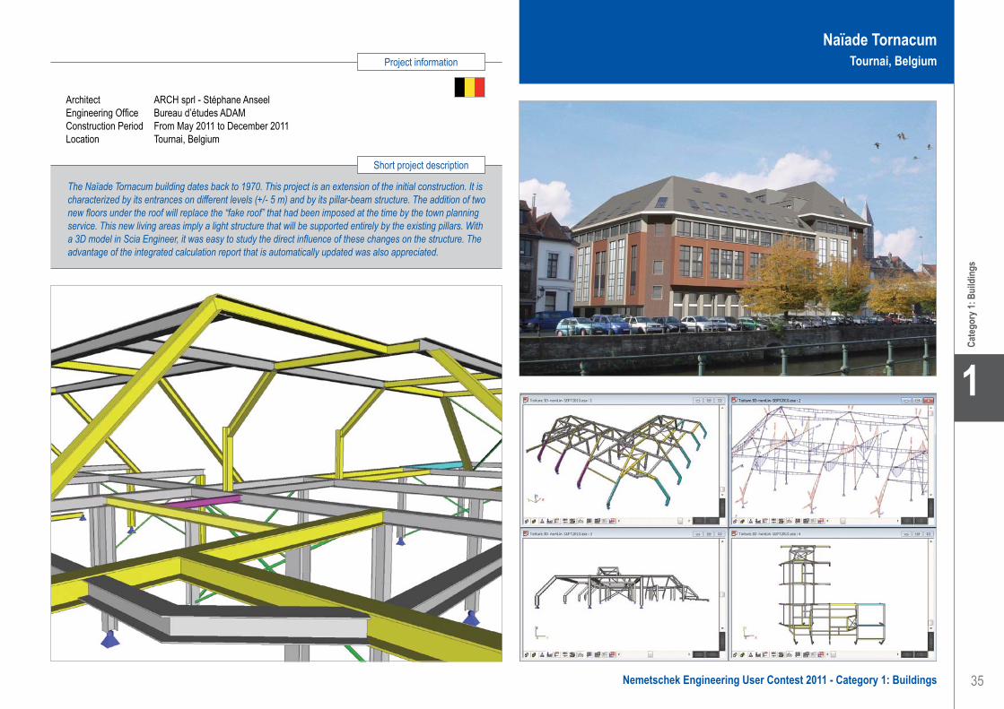
35
Project information
Short project description
Nemetschek Engineering User Contest 2011 - Category 1: Buildings
Cate
gory
1: B
uild
ings
1
Naïade TornacumTournai, Belgium
Bureau d’Etudes ADAM. . . . . . . . . . . . . . . . . . . . . . . . . . . . . . . . Naïade Tornacum - Tournai, Belgium
Architect ARCH sprl - Stéphane AnseelEngineering Office Bureau d’études ADAMConstruction Period From May 2011 to December 2011Location Tournai, Belgium
The Naïade Tornacum building dates back to 1970. This project is an extension of the initial construction. It is characterized by its entrances on different levels (+/- 5 m) and by its pillar-beam structure. The addition of two new floors under the roof will replace the “fake roof” that had been imposed at the time by the town planning service. This new living areas imply a light structure that will be supported entirely by the existing pillars. With a 3D model in Scia Engineer, it was easy to study the direct influence of these changes on the structure. The advantage of the integrated calculation report that is automatically updated was also appreciated.

36
1
Cate
gory
1: B
uild
ings
Software: Scia Engineer
Bureau d’Etudes Lemaire sprl . . . . . . . . . . . . . . . . . . . . . . . . . . . Crematorium - Welkenraedt, Belgium
Crématorium - Welkenraedt, Belgique
Surfaces: 3.000 m² Hauteur: 15 m
DescriptionL’intercommunale du C.F.R. qui gère l’unique crématorium de la région liégeoise a décidé de construire un second centre funéraire. Celui-ci, nommé « Centre Funéraire de l’Est » en raison de sa position géographique dans le pays, sera composé de deux bâtiments comprenant 3 nouveaux fours modernes situés en sous-sol, deux salles de réception modulables pouvant accueillir jusqu’à 500 personnes, un restaurant et des locaux administratifs. La surface au sol du bâtiment est de 3.000 m². Cet ouvrage, situé sur les hauteurs de Welkenraedt, s’intègre remarquablement dans son habitat naturel grâce à sa toiture verte multi-facette couvrant l’ensemble de l’ouvrage. Cette toiture est une fidèle représentation de la topographie du terrain naturel situé à l’emplacement de la construction.
Modélisation Le souhait de l’Architecte Daniel Dethier est de créer un ouvrage massif et durable dans le temps. Les parois
sont composées d’un voile extérieur en béton armé dont l’épaisseur est de 20 cm, d’une âme isolante en cellulose dont l’épaisseur est de 30 cm, d’un voile intérieur en béton armé dont l’épaisseur est de 12 cm. Le visiteur est confronté en permanence à du béton, blanc à l’extérieure et peint à l’intérieur. Cet ouvrage en béton possède certains nœuds très compliqués dont le logiciel de calcul a permis de faciliter l’évaluation des efforts.
Scia Engineer s’est même avéré incontournable pour le design de la toiture multi-facette et son interface avec la structure en béton. Cette toiture couvre l’ensemble des deux bâtiments. Elle est réalisée en lamellé collé et comprend des poutres principales, de 90 cm de hauteur, définissant les facettes de la toiture, et des poutres secondaires de 60 cm de hauteur. Ces poutres secondaires supportent la toiture verte et le faux plafond en panneaux douglas.
L’utilisation du module 3D à permis, outre de calculer les profils en lamellés collés, de connaitre les réactions exactes de cette toitures sur la structure en béton.
L’impact de cette couverture a été un point très sensible dans l’étude puisque ses différents pans inclinés créent des efforts horizontaux qui peuvent être très importants selon la méthode et l’orientation du contreventement choisi ; la détermination de ceux-ci, en tenant compte également des contraintes architecturales, a été fortement facilité pour la modélisation entière de la structure.
ConclusionLe logiciel Scia Engineer permet à l’aide de son module 3D de calculer aisément des structures dont la complexité géométrique rendrait pratiquement impossible l’évaluation réaliste des efforts de la structure. Cette facilité d’utilisation du logiciel ainsi que la fiabilité des résultats fournis font du logiciel Scia Engineer un outil efficace.
Créée en 2000 sous l’impulsion d’un jeune ingénieur, le Bureau d’études Lemaire sprl réalise des études techniques dans les domaines de l’industrie, du génie civil, du bâtiment et des infrastructures. Il se distingue par son dynamisme, son savoir-faire et ses compétences. Le Bureau d’études Lemaire sprl est composé d’une équipe solide de 25 personnes, comprenant de jeunes ingénieurs et dessinateurs DAO hautement qualifiés, vouant une passion pour la construction et participant activement à la conception, au développement et à la réalisation des projets.
Dès la naissance d’un projet, le Bureau d’Etudes Lemaire sprl s’efforce de dégager des solutions techniques créatives et originales respectant la dimension architecturale souhaitée par son concepteur.
Avec des outils informatiques performants, le Bureau d’études Lemaire sprl offre à sa clientèle un service moderne, innovant et d’excellente qualité.
Bureau d’Etudes Lemaire sprlContact Hugues WiklinAddress Route du Condroz 404 4031 Angleur, BelgiumPhone +32 43666040Email [email protected] www.belemaire.be

37
Project information
Short project description
Nemetschek Engineering User Contest 2011 - Category 1: Buildings
Cate
gory
1: B
uild
ings
1
CrematoriumWelkenraedt, Belgium
Bureau d’Etudes Lemaire sprl . . . . . . . . . . . . . . . . . . . . . . . . . . . Crematorium - Welkenraedt, Belgium
The funeral centre of Liege decided to build a new crematorium in Welkenraedt. This 3.000 m² large construction consists in two concrete buildings. The major walls are made of two reinforced concrete shells that are separated by a cellulose insulation layer. These thick walls give an impression of massiveness as desired by the author of the project. Both buildings are covered by a multifaceted roof with a glued laminated timber structure. This geometrical complicated wood structure and its interaction with the concrete structure could not be studied without using the 3D design software Scia Engineer.
Owner Intercommunale Centre Funéraire de Robermont scrlArchitect Dethier ArchitecturesGeneral Contractor FRANKI s.a.Engineering Office Bureau d’Etudes Lemaire sprlConstruction Period From August 2010 to March 2012Location Welkenraedt, Belgium

38
1
Cate
gory
1: B
uild
ings
Bureau d’Etudes Lemaire sprlContact Hugues WiklinAddress Route du Condroz 404 4031 Angleur, BelgiumPhone +32 43666040Email [email protected] www.belemaire.be
Technifutur - Liège, Belgique
Surfaces: 1.200 m² Hauteur: 17 m
DescriptionTechnifutur a.s.b.l. est un centre de compétences dont la mission est la formation des sociétés à l’industrialisation, dans 12 domaines d’activités différents (automatisation, électricité, micro-technologie, etc.). Ce centre poursuit son développement en construisant trois nouvelles extensions, dont une sous la forme d’une tour de 4 niveaux totalisant une surface de plancher de 1.200 m². La forme du bâtiment est dictée par le souhait de ne pas réduire le nombre de places de parking existantes. Le bâtiment se développe par conséquent en hauteur. Il repose sur un socle en béton dont l’épaisseur est variable.
Ce socle est lui-même assis sur 4 colonnes en béton situées en retrait. Afin de limiter les charges sollicitant le socle, la structure des étages est constituée d’une ossature métallique légère et les planchers sont de type collaborant.
Modélisation de la structureCette tour est composée d’une dalle en béton armé assise sur 4 colonnes et supportant la structure métallique des 4 étages, et d’une zone de circulation verticale en béton. Le socle en béton présente un porte-à-faux de 2.5 m et 3.7 m. Ce principe structurel fort sollicitant pour ce premier plancher nous à conduit à le réaliser en béton armé de forte épaisseur et à utiliser pour la construction des étages une ossature la plus légère possible, soit une structure métallique, des planchers collaborant acier-béton et une toiture en bacs acier. Cet allègement de la structure des étages a permis de limiter l’épaisseur du socle à une valeur variable entre 40 et 80 cm. La déformation maximale attendue du socle est de 8 mm. La stabilité au vent de la structure est entièrement réalisée par un système de contreventements dans les planchers métalliques ramenant les efforts horizontaux dans la zone de circulation verticale en béton jouxtant la tour.
La structure a été modélisée en 3D par Scia Engineer en intégrant les deux matériaux, acier et béton. L’intégration des différentes raideurs dans le logiciel ainsi que l’utilisation du module élément non linéaire - traction seule - pour les contreventements à permis de définir avec précision les déformations de la structure et la répartition des efforts.
ConclusionDès l’avant-projet, le logiciel Scia Engineer et son module 3D ont été utilisé afin d’aider à la conception de la structure et de définir le système structurel le plus efficace, béton ou acier-béton, pour atteindre l’objectif architectural d’une tour sur 4 colonnes rentrantes. Ce logiciel a été d’une aide indispensable de la conception à l’exécution du projet, garantissant une rapidité et une précision à l’étude de stabilité.
Créée en 2000 sous l’impulsion d’un jeune ingénieur, le Bureau d’études Lemaire sprl réalise des études techniques dans les domaines de l’industrie, du génie civil, du bâtiment et des infrastructures. Il se distingue par son dynamisme, son savoir-faire et ses compétences. Le Bureau d’études Lemaire sprl est composé d’une équipe solide de 25 personnes, comprenant de jeunes ingénieurs et dessinateurs DAO hautement qualifiés, vouant une passion pour la construction et participant activement à la conception, au développement et à la réalisation des projets.
Dès la naissance d’un projet, le Bureau d’Etudes Lemaire sprl s’efforce de dégager des solutions techniques créatives et originales respectant la dimension architecturale souhaitée par son concepteur.
Avec des outils informatiques performants, le Bureau d’études Lemaire sprl offre à sa clientèle un service moderne, innovant et d’excellente qualité.
Software: Scia Engineer
Bureau d’Etudes Lemaire sprl . . . . . . . . . . . . . . . . . . . . . . . . . . . Technifutur Tower - Liège, Belgium

39
Project information
Short project description
Nemetschek Engineering User Contest 2011 - Category 1: Buildings
Cate
gory
1: B
uild
ings
1
Owner Technifutur a.s.b.l.Architect Ateliers d’architecture de Lavaux - Architectes urbanistes ValentinyGeneral Contractor MOURY s.a.Engineering Office Bureau d’Etudes Lemaire sprlConstruction Period From August 2010 to August 2011Location Liège, Belgium
In order to respond to the growth of their business, Technifuture asbl has decided to build three new building extensions with a car park underneath. One of them is a tower with an area of 1.200 m². This tower has the particularity of having four levels built on a concrete slab that lay on four columns. The four levels are made of steel frames and composite floors to reduce the dead load on the concrete slab while allowing overhangs of the edges. From the beginning of the project, Scia Engineer helped to design the best structure, concrete or composite steel-concrete.
Technifutur TowerLiège, Belgium
Bureau d’Etudes Lemaire sprl . . . . . . . . . . . . . . . . . . . . . . . . . . . Technifutur Tower - Liège, Belgium

40
1
Cate
gory
1: B
uild
ings
Constructa Ltd . . . . . . . . . . . . . . . . . . . . . . . . . . . . . . . . . . . . . . . Extension of the Oncological Hospital - Ruse, Bulgaria
Software: Scia Engineer
Constructa LtdContact Vihrena GardevaAddress 16, Tsurkovna nezavisimost str. fl.13 7000 Ruse, BulgariaPhone +359 82 820702Email [email protected]
Extension of the Oncological Hospital - Ruse, Bulgaria
The oncology centre in the region of Ruse, with the support of the municipality of Ruse, planned an extension of the local oncology hospital. The total area of about 1500 square m is composed of three separate buildings - one four-storey polyclinic block, one two-storey hospital block and a specialized treatment bunker. The design of the first two blocks was more or less traditional - concrete structures, 7 degree seismicity by the Medvedev-Sponheuer-Karnik scale, stairs, elevators, shades. A very untraditional task was the block for radiation therapy - we called it “the bunker” because of its size and function. A digital accelerator, that is the source of radiation, had to be situated there. There were three levels of protection - for the personnel, for the adjacent parts of the hospital and for the environment. The vicinity of a big public building was a complication too. Together with the radiation physicists, we chose the combined protection method - steel screens for the roof and heavy concrete for the front wall towards the shopping mall across the street.
Challenges, specific experiencesUnlike other cases, in which the structural elements seem too big and too expensive to the owners, this time the elements of the bunker were too big for us, the designers. The walls were 2.1 m, 1.6 m, 1.4 m thick. The roof slab had a thickness of 1.5 m with a 0.33 m steel implant in the middle. With the help of Scia Engineer we designed the roof slab pouring process in three stages. After the first stage the steel implant was to be mounted. We introduced the characteristics of barytes concrete in the model. The mines produced baryte flour and sand for finishing layers, but we needed a bigger grain diameter. So we took all the scrap from the mine, that is, the leavings after sowing the baryte material. Still the diameter was about 8 mm, and that was introduced in Scia Engineer. At the contact area, the leakage of bigger grains into the barytes concrete was prevented by an implanted steel mesh. Because of the different consistency, leakage of finer grains could not be stopped. So the adjacent elements’ concrete was prepared with barytes sand. We also made some additional models to check the formwork and in particular its tightening ropes for the process of pouring the heavy concrete in it. The building company Glavbulgarstroy did some
experimental research on the heavy concrete to configure the time for gathering strength, creeping, and compactness. Because of the radiation admission restrictions, the compactness of both traditional and heavy concrete was to be precisely checked. Additional agents were forbidden. The builders did a great job with pouring the concrete. They managed to reach the necessary quality with simple methods like vibrating, continuous pouring, strict control of the temperature of the concrete and the environment and, of course, perfect organization. For the first time we had to deal with temperature load on the formwork. May be we had to expect that, but on the day after the pouring of the concrete, the formwork of the walls was really hot. Checks showed that the extension of the tightening ropes of the formwork will not result in impermissible geometry changes.
The construction started in November 2009 and was finished in December 2010. The concrete works were performed by Glavbulgarstroy, Ruse and the finishing works by Roan 94, Ruse. All the participants in this project formed a specialized engineering holding for radiation therapy complexes. So far the tests show perfect quality. The UK technology team gave a very high praise of the builders work, but the final results for radiation’s control will be obtained when the digital accelerator starts working at full power.At its 45th anniversary this year, the Chamber of Bulgarian Architects nominated this project as one of the best for the period.
This project gave us, the designers and the builders, a unique experience. We think of continuing the investigation of radiation diffusion with Scia Engineer fire heat modeling instruments. A more precise research of the material’s characteristics may give us the opportunity to reduce the size of the elements and to guarantee the radiation security not just on the ground, but on upper floors. Composite sections for slabs, steel and concrete, lead and concrete, or lead, steel and concrete, might be of a better economical effect. If we could model a slab to a slab contact, and input friction coefficients, box-formed sections, filled with water, sand, soil, etc. could be part of the structures, as Scia Engineer allows the introduction of any material’s behavior.
Constructa Ltd is a structural design agency, established in Ruse, Bulgaria.
Since its foundation in 2001, the company provides structural consulting to public and private companies.
We have good experience in the chemical industry; we worked a lot with physicists, chemists, technologists, physicians, etc. In such projects a structural engineer has to be really inventive and at the same time strictly observe the technology rules. The structural design agency should gather and assimilate a lot of
specific information and carefully sift it to extract all the details that affect not just the structure but the entire construction process.
A very important aspect of the industrial design is adapting the technological know how to the local geophysical and climatic conditions and norms.
We are trying to do our best to provide reliable and adequate collaboration to specialized industrial and social initiatives.

41
Project information
Short project description
Nemetschek Engineering User Contest 2011 - Category 1: Buildings
Cate
gory
1: B
uild
ings
1
Constructa Ltd . . . . . . . . . . . . . . . . . . . . . . . . . . . . . . . . . . . . . . . Extension of the Oncological Hospital - Ruse, Bulgaria
Owner Regional Oncology Complex, RuseArchitect Ventsislav IlievGeneral Contractor Radiation Therapy ConcortiumEngineering Office Constructa LtdConstruction Period From September 2009 to December 2010Location Ruse, Bulgaria
Extension of the Oncological HospitalRuse, Bulgaria
The extension of the Ruse Oncology Hospital of 1.500 m2 total area concerns a polyclinic block, a hospital block and a specialized radiation therapy bunker. Three levels of radiation protection were executed, namely for the personnel, for the adjacent parts of the hospital and for the environment. The protection method was combined - steel screens for the roof and heavy concrete for the walls. The construction started in November 2009 and was finished in December 2010. The specialized concrete works were performed by Glavbulgarstroy, Ruse.

42
1
Cate
gory
1: B
uild
ings
Constructa Ltd is a structural design agency, established in Ruse, Bulgaria.
Since its foundation in 2001, the company provides structural consulting to public and private companies.
We have good experience in the chemical industry; we worked a lot with physicists, chemists, technologists, physicians, etc. In such projects a structural engineer has to be really inventive and at the same time strictly observe the technology rules. The structural design agency should gather and assimilate a lot of
specific information and carefully sift it to extract all the details that affect not just the structure but the entire construction process.
A very important aspect of the industrial design is adapting the technological know how to the local geophysical and climatic conditions and norms.
We are trying to do our best to provide reliable and adequate collaboration to specialized industrial and social initiatives.
Radiation Therapy Complex - Plovdiv, Bulgaria
The oncology centre in the region of Plovdiv, with the support of the municipality of Plovdiv, planned an extension to the local hospital. A radiation therapy complex of about 1.300 square metres of total area was designed.
The existing building consisted of public zones for patients and specialized zones for medical equipment.
We designed the public zones more or less traditionally - concrete structures, 9 degree seismicity by the Medvedev-Sponheuer-Karnik scale, stairs, elevators, shades. The blocks for radiation therapy, bulky and heavy structures, had to act together with the slimmer common structures.
There were three levels of protection from the radiation sources - for the personnel, for the adjacent parts of the hospital and for the environment. In this case the radiation physicists chose unified protection method - steel screens for both the roof and walls.
Challenges, specific experiencesUnlike other cases in which the structural elements seem too big and too expensive to the owners, this time the elements of the bunker were too big for us, the designers. The walls are 2.1 m, 1.6 m, 1.4 m thick. The roof slab is 1.5 m thick with a 0.33 m steel implant in the middle.
With the help of Scia Engineer we designed the roof slab that is cast in three stages. After the first stage the steel implant is mounted.
The specific task in this project was to include the steel screens into the walls. These are 0.1 m thick vertical steel plates placed inside the walls. One wall had a single screen in it and the other two - 3 separate screens with a distance of 0.1 m from each other. The size of the screens was 3.70 x 4.65 m. We designed supporting structures for these steel screens. Their function was to fix the vertical position of the plates, to redistribute the load to the concrete wall below and, most important, to allow for strict tightening so that no bubbles of air remained between the individual plates.
Firstly, the basic horizontal frame has to be leveled and fixed to the concrete base.
Secondly, the exterior verticals and diagonals are to be mounted.
The next stage is to cover the outer verticals with steel plates sized 1 x 0.5 x 0.01 m and fix them.
Thus something like a cage is formed. In this cage two primary screens of 10 mm steel plates and supporting vertical profiles are mounted. The verticals function as guides for disposing all the necessary plates.
Tightening ropes go through no more than two separate plates, otherwise a channel for radiation leakage might be formed.
The use of Scia EngineerIn Scia Engineer we checked the supporting structure for every stage of assembly of the steel plates, and we also used it to illustrate the process. Due to its easy use and attractive graphical output, we often use Scia Engineer pictures and supplementary models as a 3D illustration of the general idea, like angular retaining walls, stairs, geometrically complicated architectural elements, etc.
The project got a building permit in December 2010. The building company has not yet been chosen. The construction is to start in 2011.
Software: Scia Engineer
Constructa Ltd . . . . . . . . . . . . . . . . . . . . . . . . . . . . . . . . . . . . . . . Radiation Therapy Complex - Plovdiv, Bulgaria
Constructa LtdContact Vihrena GardevaAddress 16, Tsurkovna nezavisimost str. fl.13 7000 Ruse, BulgariaPhone +359 82 820702Email [email protected]

43
Project information
Short project description
Nemetschek Engineering User Contest 2011 - Category 1: Buildings
Cate
gory
1: B
uild
ings
1
Owner Regional Oncology Complex, PlovdivArchitect Ventsislav IlievEngineering Office Constructa LtdConstruction Period From April 2011 to April 2012Location Plovdiv, Bulgaria
The project is about the extension of the Plovdiv Oncology Centre, more specifically a radiation therapy complex of about 1.300 m2. The building consists of public zones for patients and specialized zones for medical equipment. The walls of the radiation therapy blocks are 2.1 m, 1.6 m and 1.4 m thick. The roof slab has a thickness of 1.5 m with a 0.33 m steel implant in it. The chosen radiation protection method includes steel screens in walls and slabs. Specific supporting structures were designed for the process of mounting the steel plates of the screens in the walls.
Radiation Therapy ComplexPlovdiv, Bulgaria
Constructa Ltd . . . . . . . . . . . . . . . . . . . . . . . . . . . . . . . . . . . . . . . Radiation Therapy Complex - Plovdiv, Bulgaria

44
1
Cate
gory
1: B
uild
ings
Software: Scia Engineer
Renovation of Station Transit Zone ‘San de Senart’ - Paris, France
Description of the projectThe municipality of San de Senart, Paris, together with the French railway company, planned the rehabilitation of a public parking at a train and subway station. The idea was to make it more comfortable and attractive for the passengers. New lifts, stairs and ramps were added. We dealt with steel structures in this project.
These are many relatively small structures, meant to protect the interior from sound, light, wind, snow, etc. and also to decorate the building. Here we will refer to two of these structures - the so-called “pignons” and the sun-guarding hangings.A “pignon” is a kind of a pediment. It is situated about a meter away from the actual elevation. In fact this is a perforated aluminum covered deflection screen, 12 m wide and 14 m high. It is inclined and curved.The sun-guarding hangings consist of vertical supporting structures and horizontal aluminium shells.
ChallengesSome of the problems were caused by the combined ownership. The parking garage spans two streets and
the train station itself. We had to keep all structures a meter above the train station and above the ground - no foundations or anchorage allowed. Every steel structure had to be attached to the existing concrete structure.
The task got more complicated by the fact that the structure is prestressed. There was a small area for the anchors, restricted in height in a floor between the prestressing cables and in width between the concrete panels of the elevation. That makes it 80 / 80 mm per floor and per 3 m length.
Other problems came from accessibility. The train station was not to be closed during the construction process, neither were the streets. So the mounting of both the pignons and the hangings had to be done without a crane. All separate elements should be light enough to be lifted by a pulley.
SolutionsFor the “pignons” we designed a separate spatial structure, consisting of four vertical trusses and inclined front beams. Thus we created a rectangular mesh for the perforated aluminum panels. The trusses are anchored to the floor beams in the hole between the concrete panels.
With the help of Scia Engineer we designed the steel structure and obtained data about the anchoring forces and their effect to the existing structure. We anticipated the great effect of temperature loads, but the results were a surprise. We made the conclusion that temperature loads are most essential for the design of any secondary outside structural elements.
The sun-guardings at the east end of the building are situated above the train station. As we couldn’t go lower than one meter above the station’s roof, we had to choose for a cantilever hanging of 4 m in height. Anchoring is allowed at the columns - 9 m opening, at the angles 3 m cantilever floor beam. Our solution was to foreseen vertical supports, combined by a horizontal triangular truss, situated 2.5 m above the station. With the help of Scia Engineer we investigated multidirectional wind loads to ensure stability and evaluate the deformations.
Constructa Ltd is a structural design agency, established in Ruse, Bulgaria. Since its foundation in 2001, the company consulted, designed and controlled the construction of a lot of residential, public and industrial buildings, facilities, special structures. We are specialized in untraditional steel structures, seismic stability, and reconstruction of existing buildings. Our team consists of 6 people - structural engineers and technical staff, we work in collaboration with architectural and installation design agencies, building companies, geology research companies, restoration specialists, etc. We usually insist on
being a partner at the very beginning of the design process, but we often have to deal with predefined technical, economical or artistic solutions. Though we believe that the structural aspect is of primary importance in construction, sometimes our “structural” approach is subjected to pressure, torsion… These difficulties usually develop untraditional solutions. Our general policy is to understand and evaluate the aims and problems of all the participants in a construction initiative. We do our best to investigate different possibilities and present the owner with reliable information, so that the most adequate decision is taken.
Constructa LtdContact Vihrena GardevaAddress 16, Tsurkovna Nezavisimost str. fl.13 7000 Ruse, BulgariaPhone +359 82 820702Email [email protected]
Constructa Ltd . . . . . . . . . . . . . . . . . . . . . . . . . . . . . . . . . . . . . . . Renovation of Station Transit Zone ‘San de Senart’ - Paris, France

45
Project information
Short project description
Nemetschek Engineering User Contest 2011 - Category 1: Buildings
Cate
gory
1: B
uild
ings
1
Renovation of Station Transit Zone ‘San de Senart’Paris, France
The municipality of San de Senart, Paris and the French railway company planned the rehabilitation of a public parking at a train station. We designed relatively small steel structures, meant for protection from sound, light, wind, snow, etc. and for decoration. The “pignons” (pediments) are situated a meter away from the actual elevation. These perforated aluminum covered deflection screens, 12 x 14 m, are designed as separate spatial structures, consisting of vertical trusses and inclined front beams. The sunblind hangings are vertical supports, connected by a horizontal triangular truss and aluminum shells.
Owner San se Senart, Commune combs la villeArchitect Levincent-Samson EurlGeneral Contractor Magnac freresEngineering Office Constructa LtdConstruction Period From November 2009 to June 2011Location Paris, France
Constructa Ltd . . . . . . . . . . . . . . . . . . . . . . . . . . . . . . . . . . . . . . . Renovation of Station Transit Zone ‘San de Senart’ - Paris, France

46
1
Cate
gory
1: B
uild
ings
Dipl.-Ing. Manfred Ratzke Beratender Ing. für Bauwesen . . . . . . SEBILI Building for Research and Production - Potsdam, Germany
Dipl.-Ing. Manfred Ratzke Beratender Ing. für BauwesenContact Manfred RatzkeAddress Karl-Marx-Strasse 16A 16547 Birkenwerder, GermanyPhone +49 33035960400Email [email protected] www.ratzke-bb.com
SEBILI - Forschungs- und Produktionsgebäude - Potsdam, Deutschland
Entstehung des Projekts SEBILIDer Name “SEBILI” setzt sich zusammen aus den Begriffen “SEHEN”, “BILD” und “LICHT”.
SEBILI ist ein innovatives optisches Nacht-Sicherheitssystem für Fahrzeuge. Das große Interesse aus der Automobilindustrie bestärkte den Entwickler und Hersteller des Systems in der Entscheidung zum Neubau der Forschungs- und Produktionsgebäude in Potsdam bei Berlin. Mit Prof. Dr. Hasso Plattner (SAP) gewann SEBILI einen Investor, der das Unternehmen dabei unterstützt, SEBILI zur Marktreife zu führen.
Mit dem Design beauftragte man Dipl.-Ing. Christian Orth, Mannheim. Der erfahrene Architekt entwarf ein repräsentatives Bauwerk, dessen Design industrielle Sachlichkeit mit dem technologischen Führungs-anspruch des Unternehmens verbindet.
Das Gebäude erstreckt sich über eine Länge von 120 m bei einer Breite von 40 m. Die Höhe beträgt ca. 22 m. Architekt Orth gliederte das Bauwerk in drei Teile. Der mittlere Teil, intern Teil 2, ist für Forschung, Verwaltung und die Geschäftsführung vorgesehen. Ein Hochregallager ist hier ebenfalls integriert. Flankiert wird Teil 2 von den zwei spiegelbildlich angeordneten Teilen 1 und 3. Hier befinden sich die Produktionsstätten des Unternehmens. Jeder der beiden Flügel ist 40 m lang.
Die KonstruktionTeil 1 und 3 besitzen jeweils vier Geschosse und sind nicht unterkellert. Mit Ausnahme der Decken wurden die Gebäudeteile in Vollfertigteil-Bauweise errichtet. Die 28 cm starken Filigrandecken werden von Stützen in einem Raster von 5.75 x 5.70 m getragen. Die Stabilität der Konstruktion wird durch das Treppenhaus und die Außenwände gewährleistet.
Dem Büro Dipl.-Ing. Manfred Ratzke Beratender Ingenieur für Bauwesen oblag die gesamte Fertigteil¬planung inklusive Anfertigung der Montagepläne.
Teil 2 des Gebäudekomplexes ist unterkellert und besitzt fünf Geschosse. Im Gegensatz zu den flankierenden Gebäudeteilen kam hier eine Konstruktion aus Halbfertigteilen zum Einsatz. Einige
Bauteile, wie z.B. die Decke des Eingangsbereichs und die Unterzüge, wurden in Ortbeton-Bauweise hergestellt.
Ein Raster von wandartigen Trägern trägt die Überbauung mit zwei Geschossen über einem Hochregallager ab. Dabei beträgt die Spannweite einiger Träger, die gleichzeitig die Außenwände des entstehenden Innenhofes bilden, ca. 26 m. Ein optisches Highlight der Konstruktion ist die freitragende Galerie des Eingangsbereichs. Jede der dort befindlichen Treppen besitzt ein Gewicht von 4.6 t. Erhaben unterstützt die Galerie den repräsentativen Gesamteindruck des Gebäudes.
Die PlanungDie Rohbauzeit des Projekts betrug von Dezember 2006 bis Juli 2007 nur sieben Monate. Da erst im November 2006 Klarheit über die verfügbaren Krankapazitäten bestand und Änderungswünsche umgesetzt werden mussten, wurden erst in diesem Zeitraum die statischen Berechnungen mit einem Umfang von etwa 1600 Seiten und ca. 950 Pläne angefertigt.
Alle Berechnungen und Pläne, eingeschlossen die Fertigteilpläne für die Heidelberger Zement Industrie wurden von Dipl.-Ing. Manfred Ratzke Beratender Ingenieur für Bauwesen angefertigt.
Verwendete SoftwareDie anspruchsvollen Aufgaben des Projekts konnten nur mithilfe effektiver Software erfolgreich erfüllt werden. Aus diesem Grund nutzt das Büro Dipl.-Ing. Manfred Ratzke Beratender Ingenieur für Bauwesen seit 1993 die Statikprogramme von FRILO in Verbindung mit den CAD- und BAMTEC®-Programmen von GLASER -isb cad-.
Über 20 Jahre kompetente BeratungDas Ingenieurbüro Dipl.-Ing. Manfred Ratzke wurde im Jahr 1990 gegründet. Das Büro mit Sitz in Birkenwerder bei Berlin deckt mit seinen Projekten eine Bandbreite von Gewerbeobjekten bis zu großen Industrie¬bauten ab. Dabei wird stets das Ziel verfolgt, alle Projekte wirtschaftlich und termingerecht zu realisieren. Neben seiner Tätigkeit in Deutschland ist Dipl.-Ing. Manfred Ratzke auch im europäischen Ausland (z.B. Österreich, Griechenland, Türkei und in Polen) aktiv gewesen.
Weitere Aktivitäten:• Internetportal “Statik-Online”, über das
Angebote über Statiken und Zeichnungen für Bauvorhaben angefordert werden können aber auch für einzelne Bauteile im Rahmen einer Dienstleistung, Berechnungen durchgeführt werden.
• Zukunftsweisendes “Zero Emission Hotel” der Katholischen Jugend in Berlin mit der Wärmeschutzberechnung nach DIN 18599.
• Verschiedene Projekte derzeit in 4 Bundesländern.
Software: Frilo Statics, GLASER -isb cad-

47
Project information
Short project description
Nemetschek Engineering User Contest 2011 - Category 1: Buildings
Cate
gory
1: B
uild
ings
1
SEBILI Building for Research and ProductionPotsdam, Germany
Dipl.-Ing. Manfred Ratzke Beratender Ing. für Bauwesen . . . . . . SEBILI Building for Research and Production - Potsdam, Germany
Owner Prof.-Dr. Hasso PlattnerArchitect Dipl.-Ing. Architekt Christian OrthGeneral Contractor PB Bauservice GmbHEngineering Office Dipl.-Ing. Manfred RatzkeConstruction Period From December 2006 to February 2008Location Potsdam-Golm, Germany
The project is about the extension of the research and production capacities of developer and producer of the optical safety system SEBILI (anti-dazzle car kit). It was decided to build new corporate headquarters in Potsdam. The construction of the three-building complex with four and five stories was made in prefab parts of reinforced concrete. One of the highlights is the self-supporting foyer gallery of cast-in-place concrete. Dipl-Ing. Manfred Ratzke, the consulting engineer, took care of the entire structural design, including all plans for cast-in-place concrete and prefab parts of the 120 x 40 m large complex.

48
1
Cate
gory
1: B
uild
ings
DuPlan s.r.o.Contact Tomáš Duba, Radovan KrútekAddress Mikulášska 15 81101 Bratislava, Slovak RepublicPhone +421 255569843Email [email protected] www.duplan.sk
Galvaniho Business Centrum IV - Bratislava, Slovensko
Novostavba „Galvaniho Business Centrum IV“ je štvrtý samostatný objekt administratívnych celkov v lokalite na Galvaniho ul. v Bratislave v blízkosti nákupného centra Avion. Pôdorysne má objekt nepravidelný tvar s dvojicou vnútorných presvetlovacích átrií a je rozdelený na šesť dilatačných častí. Dve časti sú výlučne suterénne s hornou doskou dimenzovanou na pojazd a parkovanie vozidiel. Zvyšné štyri dilatačné časti tvoria samotný objekt administratívnej budovy. Objekt bude plne podpivničený - v časti dvojúrovňovým suterénom, pričom suterény čiastočne presahujú rozmery nadzemných podlaží, bude mať šesť plnohodnotných nadzemných podlaží a siedme malé technické podlažie a bude zastrešený plochou strechou. Modulová osnova administratívnej budovy je v pozdĺžnom smere po 7.5 m so skrátenými modulmi pri dilatácii a doplnkovými modulmi 5.0 m, v priečnom smere je kombinácia modulov 7.5 + 5.0 m.
Na základe geologického prieskumu sú základové konštrukcie navrhnuté ako plošné (vystužené pätky a pásy) siahajúce do únosných štrkových vrstiev s tým, že pod základovými prvkami sa upravilo podložie
(štrkopieskové vibrostĺpy fy. Keller) tak, aby bola dosiahnutá únosnosť min. Rd = 500 kPa.
Zvislé nosné konštrukcie tvorí systém stĺpov so stužujúcimi vnútornými resp. obvodovými stenami, všetko z monolitického železobetónu. Stĺpy sú prierezu 500/500 mm, v suteréne aj 500/800 mm. Steny majú prevažne hrúbku 200 mm, obvodové suterénne 300 mm, masívne stužujúce krátke steny majú hrúbku 400 alebo 500 mm.
Horizontálne nosné konštrukcie sú tvorené monolitickými železobetónovými stropnými doskami, navrhnutými ako bezprievlakové stropy, betónované spolu s obvodovými trámovými stužidlami. Do dosiek sú nad stĺpmi osadené a zabetónované roznášacie oceľové hlavice alebo špeciálne šmykové trny. Schodiská sú riešené ako prefabrikované železobetónové dosky ukladané do ozubov v monolitických podestách a medzipodestách. Doska nad dilatačnými celkami E a F (len suterénne časti) je navrhnutá hrúbky 300 mm s monolitickými hlavicami hrúbky 400 mm a šmykovou výstužou AVI. Od stropu nad 1. poschodím sú obvodové nosníky (nadpražia) prefabrikované s výnimkou úsekov staticky a technologicky nevhodných. Prefabrikované nosníky sa stykujú prevažne na úrovni modulovej osi, ku stĺpu resp. stene sú prikotvené cez kotevnú výstuž. Z prefabrikátov vyčnievajú kotevné prúty pre napojenie monolitických parapetov. Prefabrikované aj monolitické nadpražia majú šírku okrem výnimiek 200 mm, parapety 150 mm s rozšírením v mieste stĺpov. Konštrukcie výťahových šácht v átriách od úrovne 1.NP sú oceľové s presklením.
Spoločnosť DuPlan bola založená v r. 2004 ako obchodno - servisná spoločnosť na podporu činnosti voľného združenia niekoľkých inžinierov. Prakticky okamžite sa však pretransformovala na projektovú organizáciu.
Špecializujeme sa na statiku nosných konštrukcií pozemných stavieb, predovšetkým na vyhotovenie projektovej dokumentácie nosných konštrukcií stavieb, technické poradenstvo pre statiku a dynamiku stavieb, statické a dynamické výpočty nosných konštrukcií, overenie nosných konštrukcií z hľadiska mechanickej
odolnosti a stability, vypracovávanie odborných posudkov a odhadov, vykonávanie odborného autorského dohľadu nad uskutočňovaním stavieb. Potrebnú odbornosť zabezpečujú naši kľúčoví spolupracovníci, autorizovaní inžinieri Slovenskej komory stavebných inžinierov. V súčasnosti je užší tím tvorený piatimi inžiniermi a niekoľkými externými spolupracovníkmi.
Software: Scia Engineer
DuPlan s.r.o. . . . . . . . . . . . . . . . . . . . . . . . . . . . . . . . . . . . . . . . . Galvaniho Business Centrum IV - Bratislava, Slovak Republic

49
Project information
Short project description
Nemetschek Engineering User Contest 2011 - Category 1: Buildings
Cate
gory
1: B
uild
ings
1
Owner Galvaniho 4 s.r.o., BratislavaArchitect Jozef DraškovičGeneral Contractor Lindner Slovakia s.r.o.Engineering Office Draškovič s.r.oConstruction Period From March 2008 to April 2010Location Bratislava, Slovak Republic
This project is about the Galvaniho Business Centrum IV. It is a complex of administration buildings with 7 above ground storeys and an extended two-level underground car park (parking space 12.400 m2, shops and stores 4.800 m2, offices 30.500 m2). The construction is composed of 4 dilatation blocks, a monolithic concrete skeleton with diaphraghm and carrying walls as well as monolithic girderless slabs. Two dilatation blocks of underground car parks are situated beneath the above ground parts.
Galvaniho Business Centrum IVBratislava, Slovak Republic
DuPlan s.r.o. . . . . . . . . . . . . . . . . . . . . . . . . . . . . . . . . . . . . . . . . Galvaniho Business Centrum IV - Bratislava, Slovak Republic

50
1
Cate
gory
1: B
uild
ings
FAKTOR Civil EngineeringContact Jan PleijteAddress Postbus 7149 4330GC Middelburg, The NetherlandsPhone +31 118-614722Email [email protected] www.faktorbv.nl
Dijkpaviljoen ‘t Puntje - Vlissingen, The Netherlands
De Punt en frituur ‘t Puntje zijn sinds jaar en dag twee onlosmakelijk met elkaar verbonden begrippen in Vlissingen. De Punt is het uitstekende dijkdeel naast de sluizen van Vlissingen, het biedt een prachtig uitzicht op de Westerschelde en de voorbijvarende schepen. Het Puntje was oorspronkelijk een tot frituur omgebouwde schaftkeet.
Voor dit unieke punt heeft de opdrachtgever de architect opdracht gegeven een dijkpaviljoen in twee verdiepingen te ontwerpen; het moest de naam Punt waardig zijn.
Dit paviljoen wordt geplaatst op een hoofdwaterkering, hetgeen inhoudt dat er niet in de dijk gegraven of geheid mag worden. De bouwplaats is beperkt en ligt niet waterpas.
Het idee was om een prefab constructie in een keer op zijn plaats te zetten. In overleg is dit een staalconstructie geworden, beslissende factoren waren gewicht en transporteerbaarheid.
De architect heeft een opbouw bedacht die uit diverse driehoeken (puntjes) bestaat, die in alle gevels, vloer en dak zichtbaar zijn. Verder is de link gelegd met de schepen die op enkele honderden meters dag in dag uit passeren. Dit heeft geresulteerd in een vakwerk bestaande uit kokers 120 x 120 x 6.3 mm met een beplating van staalplaat (8 mm) met daarin patrijspoorten.
Het eerste ontwerp ging uit van staalplaat die aan de binnenzijde verstijfd werd door bulb-ijzers, zoals in de scheepsbouw wordt toegepast. Dit ontwerp is omwille van fabricage-technische redenen afgevallen. De begane grond- en verdiepingsvloer zijn in de berekening als staalplaat 10 mm ingevoerd. Uiteindelijk zijn deze vloeren in een houten balklaag uitgevoerd. Alleen het dakterras is in staalplaat met een dikte van 10 mm uitgevoerd.
De westzijde en een deel van de zuidzijde zijn volledig voorzien van glas, zodat men op begane grond en verdieping de zeeschepen van Terneuzen naar Zeebrugge kan zien varen. Het dakterras, volledig uitgevoerd in stalen platen, geeft een 360 graden zicht over de stad Vlissingen en de Westerschelde.
De kleur van het paviljoen moest overeenstemmen met de kleur van het reeds aanwezige kunstwerk.
Het complete stalen casco is door de staalbouwer Hillebrand Konstruktie op 12 februari 2010 per ponton door het kanaal door Walcheren gevaren en direct na de zeesluizen op de dijk getakeld.
De constructie is gemodelleerd met Scia Engineer, gebruik makend van 3D frame en 2D plate.
De begane grondvloer is opgebouwd uit IPE 330 die de belastingen gelijkmatig over het dijklichaam moeten verdelen. Deze IPE’s zijn in het model verend ondersteund.
Na het waterpas stellen van de constructie zijn deze IPE’s volledig ondersabeld. Wrijving tussen de bekleding van het dijklichaam en deze ondersabeling dient de horizontale krachten over te brengen op de ondergrond.
Vanuit Scia Engineer is het model in DWG- formaat aan de staalbouwer geleverd. Deze heeft het in zijn tekenprogramma verder uitgewerkt.
Algemene gegevens:• Het grondvlak is een gelijkzijdige driehoek met zijden
van 16.700 mm en een oppervlak van 120 m2/laag• De verdiepingshoogte is 3.500 mm; het dakterras ligt
op 7.0 m• Het totaal hijsgewicht van de staalconstructie
bedroeg ca. 35 ton.
FAKTOR Civil Engineering bv is een ingenieursbureau met 12 medewerkers en een omzet van ca € 1.000.000. Het bureau bestaat in januari 2011 30 jaar.
De werkzaamheden omvatten het berekenen en tekenen van beton-, hout- en staalconstructies, zowel het hoofdontwerp als de uitwerking van de constructies op detailniveau.
In 2006 werd voor het constructief ontwerp van de geluidswal met showroom langs de A2 bij Utrecht de Nationale Staalprijs in ontvangst genomen.
De projecten bevinden zich hoofdzakelijk in de provincie Zeeland en Westelijk Noord- Brabant.
De opdrachtgevers zijn architecten en aannemers in de provincie alsmede semi-overheden zoals nutsbedrijven en waterschappen en industrie uit het Sloegebied. Verder wordt een deel van de omzet verkregen uit opdrachten van particulieren.
Een bouwkundige afdeling verzorgt ontwerp- en bestektekeningen alsmede bestekken, EPN-, daglicht- en ventilatieberekeningen.
Software: Scia Engineer
FAKTOR Civil Engineering . . . . . . . . . . . . . . . . . . . . . . . . . . . . . Sea Front Restaurant ‘t Puntje - Vlissingen, The Netherlands

51
Project information
Short project description
Nemetschek Engineering User Contest 2011 - Category 1: Buildings
Cate
gory
1: B
uild
ings
1
Owner Dijkpaviljoen bvArchitect Joos NijsseGeneral Contractor Hillebrand KonstruktieEngineering Office FAKTOR Civil EngineeringConstruction Period From August 2009 to February 2010Location Vlissingen, The Netherlands
Along de Westerschelde, near the locks of Vlissingen, the pavilion restaurant ‘t Puntje was placed in February 2010; it is located at the dike where cargo ships pass to and fro Antwerp.The whole building is shaped in triangles, formed by rectangular tubes of 120 x 120 x 6.3 mm and a façade of 8 mm steel plates. The triangles are shaped as 2D truss. Because it was not allowed to dig or pile into the dike, the prefab building was placed on the dike without foundation or fixation. It was transported by ship to its final destination and hoisted up the dike.
Sea Front Restaurant ‘t PuntjeVlissingen, The Netherlands
FAKTOR Civil Engineering . . . . . . . . . . . . . . . . . . . . . . . . . . . . . Sea Front Restaurant ‘t Puntje - Vlissingen, The Netherlands

52
1
Cate
gory
1: B
uild
ings
Immeubles de Logements Protégés - Le Mont-sur-Lausanne, Suisse
Description de l’objetLe projet final comporte cinq immeubles de logements protégés qui se situent au Mont-sur-Lausanne. Il s’agit de logements permettant l’accueil de personnes âgées semi-indépendantes. Pour l’heure, et afin de permettre un transfert des occupants de manière efficace et agréable, seuls trois des cinq bâtiments ont été réalisés.
La géométrie du bâtiment permet d’épouser la topographie du terrain grâce à ses décalages successifs. La volonté était alors d’obtenir une totale liberté de mouvement devant l’entrée principale en se soustrayant de tout porteur.
Les trois bâtiments sont quasi-identiques. Ils comportent chacun quatre étages dont tous les éléments porteurs sont en béton armé.
Nécessité du logiciel Scia EngineerLes porte-à-faux successifs constituent bien entendu la difficulté majeure du projet. Leurs déformations ne sont réalistes que si elles prennent en compte les rigidités
de l’ensemble des étages. Nous avons donc réalisé un modèle numérique de l’entier du bâtiment en trois dimensions afin de pouvoir simuler le comportement des porte-à-faux de la manière le plus réaliste possible.
Grâce à ce modèle, nous avons pu constater que les déformations calculées permettaient de satisfaire aux exigences des normes en matière d’aptitude au service, ceci grâce à l’apport de l’effet coque des éléments en béton armé. Cet effet n’est pas pris en compte dans un modèle 2D simplifié, lequel conduit généralement à des déformations insatisfaisantes.
Le modèle 3D permet également de localiser avec exactitude les zones fortement sollicitées. Ces dernières sont donc renforcées en conséquence afin d’assurer la sécurité structurale de l’ensemble.
Résultats, conclusionsLe modèle 3D a été réalisé dans son stade final, c’est-à-dire que le poids propre des éléments agit de manière simultanée. Afin d’être cohérent avec ce modèle, nous avons décidé en accord avec l’entreprise de garder étayés les porte-à-faux jusqu’à la prise complète de la dalle toiture.
Afin de vérifier la correspondance entre le modèle et la réalité, nous avons mesuré le déplacement vertical après le désétayage total de la structure. Nous avons finalement observé que les déformations instantanées sous le poids propre correspondaient plus ou moins aux déformations attendues (+/-1 mm).
Giacomini & Jolliet Ingénieurs SAContact Raphael DauphinAddress Ch. de Burquenet 23 1095 Lutry, SwitzerlandPhone +41 217914111Email [email protected] www.giajo.ch
Notre société est active depuis plus de 30 ans dans divers domaines de l’ingénierie. De par notre polyvalence, notre champ d’activité s’étend des travaux spéciaux aux études d’impact et expertises ainsi qu’à toutes les prestations de projet et d’exécution.
Qu’elles soient nouvelles ou existantes, nous maîtrisons les structures à ossatures bois et charpente métalliques, ainsi que les structures en béton armé et précontraint.
Récemment, nous avons complété nos compétences en nous spécialisant dans la
dynamique des structures et particulièrement le domaine parasismique.
Nous avons notamment réalisé récemment deux passages inférieurs en béton armé et précontraint à l’EPFL (2009) ainsi que 3 bâtiments pour 72 logements à Lausanne (2010).
Software: Scia Engineer
Giacomini & Jolliet Ingénieurs SA . . . . . . . . . . . . . . . . . . . . . . . . Service Flats - Mont-sur-Lausanne, Switzerland
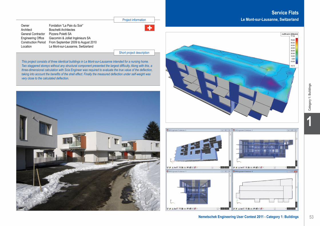
53
Project information
Short project description
Nemetschek Engineering User Contest 2011 - Category 1: Buildings
Cate
gory
1: B
uild
ings
1
Owner Fondation “La Paix du Soir”Architect Boschetti ArchitectesGeneral Contractor Pizzera Poletti SAEngineering Office Giacomini & Jolliet Ingénieurs SAConstruction Period From September 2009 to August 2010Location Le Mont-sur-Lausanne, Switzerland
This project consists of three identical buildings in Le Mont-sur-Lausanne intended for a nursing home. Two staggered storeys without any structural component presented the largest difficulty. Along with this, a three-dimensional calculation with Scia Engineer was required to evaluate the true value of the deflection, taking into account the benefits of the shell effect. Finally the measured deflection under self-weight was very close to the calculated deflection.
Service FlatsLe Mont-sur-Lausanne, Switzerland
Giacomini & Jolliet Ingénieurs SA . . . . . . . . . . . . . . . . . . . . . . . . Service Flats - Mont-sur-Lausanne, Switzerland

54
1
Cate
gory
1: B
uild
ings
GrontmijContact Michael Provost, Koen MeertAddress Meersstraat 138A 9000 Gent, BelgiumPhone +32 9 241 59 20Email [email protected] Website www.grontmij.be
Residential London Tower - Antwerp, Belgium
Project descriptionThe project London Tower is the final project of the Amca site in Antwerp at the crossroads of the Italiëlei, Noorderlaan and London Straat. It is the largest residential tower of Antwerp with an aboveground height of 76 m (22 levels) and an underground depth of 10 m (3 levels). At the tower there is also an extension building with a height of two storeys.
ChallengesThe tower needed to be build in a short period of time. Therefore some execution methods were proposed and developed. The most important was to use a sliding formwork for the central core of the building. This way of construction made it afterwards possible to execute the structural work of one floor (interior and exterior walls and floor slabs) in one week with only one freestanding tower crane with a height of ca. 85 m.
The stability of the building is ensured by the cooperation of the core with the concrete prefabricated walls that are separating the apartments and the outside walls. They are all connected by cast in place floor slabs.
Geometry of the towerThe maximum floor area is approximately 37.5 m by 18.5 m. From the tenth floor there is also a cantilever of 2.4 m. The typical floors consist of slabs with thicknesses ranging from 18 to 27 centimeters. The largest plates spans in two directions with a distance of approximately 13 m by 7.2 m.
The structural support system consists of a central core, a supporting façade wall as well as elements and concrete walls that are separating the apartments. The core is a long narrow section of 15.8 m by 3.8 m.
FoundationsBecause of its location (close to the Scheldt River), the tower is subjected to upward water pressure of 7 to 8 m.
The entire tower is partly founded on 130 piles of 160 tons (length +/- 12 m) and on slurry walls at the perimeter of the underground levels.
To prevent damage to the adjacent buildings, the slurry walls were partly executed up to the layers of the Boom clay (27 m beneath the ground level) and a special drainage system was installed.The upward pressure of the groundwater was taken by tension piles in the areas next to the tower.
The foundation plate has a thickness of 60 cm between the piles. The pile heads themselves and the thickened area below the core is 1.40 m thick.
3D modellingGrontmij developed two different 3D models of the tower to consider the differences during assembly state and in final state.
Model A, is a model for the tower in the final state where the stiffness is ensured by the cooperation between core, floor slabs and the concrete walls.
Model B is a model in which the core is raised with a sliding formwork up till the roof. For this calculation, the entire tower was stripped and we checked which wall thickness and reinforcement needed to be adjusted in comparison to the final state. The resistance to wind needed to be ensured by the rigidity of the core itself. In addition, extra shoring were added between some walls because the walls were not yet connected by slabs during this construction stage.
The difference in compression between the core and columns (because of different geometry and concrete quality) and the creep were calculated to take them into consideration during the construction phase.
For the calculation of the reinforcement and deformation of the floor slabs, individual models of each floor slab were made and were compared to the results obtained from the 3D model.
ConclusionSeveral tools from ESA-Prima Win were used for this model to easily control the results and use them for individual reinforcement calculations.
Grontmij is a multidisciplinary consulting and engineering firm for sustainable planning & design, transportation & mobility and water, energy & industry.
From a future-oriented vision, we provide quality advice and we design creative plans and projects. That way, we contribute to a better housing, working and living environment. It’s our ambition to be the best sustainable consulting and engineering firm and to add value, from A to Z, to advice, study, design, engineering, execution and management of projects.
As a publicly listed company, we are active in 350 offices with some 11.000 experts in 50 countries, and we are leaders in Europe.
Grontmij operates within three business lines, namely: Water & Energy, Transportation & Mobility and Planning & Design. These reflect the long term external market drivers such as climate change, population growth and urbanisation across the world.
Grontmij . . . . . . . . . . . . . . . . . . . . . . . . . . . . . . . . . . . . . . . . . . . . Residential London Tower - Antwerp, Belgium
Software: ESA-Prima Win, Scia Engineer

55
Project information
Short project description
Nemetschek Engineering User Contest 2011 - Category 1: Buildings
Cate
gory
1: B
uild
ings
1
The London Tower is the largest residential tower of Antwerp with an aboveground height of 76 m (22 storeys), an underground depth of 10 m (3 levels) and a surface of 37.5 m by 18.5 m. The structural support system consists of a central slided concrete core, prefabricated outside walls, flat dividing prefabricated concrete walls and cast in-situ concrete slabs. The construction time was minimized by the use of a sliding formwork for the central concrete core. The building was entirely calculated with ESA-Prima Win using a general model for the final stage and a stripped model for the construction stage of the core.
Owner AMCAArchitect Christine Conix - S/VR (Storme/Van Ranst)General Contractor Interbuild - Vanhout - ABEB - CFEEngineering Office Grontmij VlaanderenConstruction Period From April 2008 to July 2010Location Antwerp, Belgium
Residential London TowerAntwerp, Belgium
Grontmij . . . . . . . . . . . . . . . . . . . . . . . . . . . . . . . . . . . . . . . . . . . . Residential London Tower - Antwerp, Belgium

56
1
Cate
gory
1: B
uild
ings
Software: Allplan Engineering, Scia Engineer
HESCON s.r.o. . . . . . . . . . . . . . . . . . . . . . . . . . . . . . . . . . . . . . . University Campus - Trnava, Slovak Republic
HESCON s.r.o.Contact Erik HrnčiarAddress Nám. sv. Anny 20C/7269 911 01 Trenčín, Slovak RepublicPhone +421 32 6513700Email [email protected] www.hescon.sk
University Campus - Trnava, Slovak Republic
DescriptionThe extension of building SO 002 and the new building TF STU are part of a large project including the finalisation of building processes and the reconstruction of the university campus in Trnava. The five-storey reinforced concrete structure is 18 m high, 20 m wide and 119 m long and is divided into two dilatation units.
Geological conditionsThe geological exploration discovered very leaky loess in the upper part of the soil and at the depth of 10.5 m there is a thick layer of gravel with neogene underneath. The foundation process was on piles leant against the gravel layer.
Foundation structuresThe reinforced concrete columns are founded on piles Ø = 0.9 and Ø = 1.2 m of the length of 10.5 m with circular chapiters 1.500 mm high, made of reinforced concrete C25/30. The columns are wedged into the cups of the chapiters. Reinforced concrete cores are founded on a foundation slab with a thickness of 300 mm which is supported on its edges by
piles of Ø = 1.2 m with the length of 9.5 m. In the laboratories on the 1st floor there are separately dilated foundation slabs with the thickness of 400 mm used under machinery equipment which are on the edges supported by piles of Ø = 0.9 m with the length of 9.5 m.
Load bearing concrete structureThe building forms a transverse load-bearing system. The columns of rectangular and circular cross-section have the following dimensions: 380 x 450; 380 x 500; D = 420 and D = 450 mm support semi-prefabricated beams 450 x 400; 450 x 500; the beams of cross-section I 1100 and 1250 mm high. The stability in the longitudinal direction is provided by perimeter stiffeners 380 x 630 and 420 x 630 mm and monolithic reinforced concrete cores of concrete C30/37 with walls 250 mm thick. The beams and stiffeners are put on the brackets of the columns. The ceiling boards are formed by filigreed boards with the thickness of 60 mm and additional concreting of 120 mm in thickness which, after becoming monolithic, will create one unit with the board. The ceiling board is of concrete C30/37. The distance between load-bearing frames is 6.0 m.
Load bearing steel structureFor the light glassed façade there is a steel truss purlin that serves as a support. The upper and lower chords of this purlin are made from closed square cross-sections.
The connecting hall to the existing object has columns made out of circular profiles and the ceiling is composed of IPE profiles. The load bearing part of the light roof is formed by trapezoidal elements.
HESCON, Ltd., the design and static office, was established in 2008 by the authorized civil engineer Ing. Erik Hrnčiar.
After his long-term experience in the field of design managing, designing and building of load-bearing structures, the idea was born to gather a strong team of designers and structural engineers, all of whom you can meet in HESCON, Ltd today.
HESCON, Ltd. offers its clients services in consulting, design, engineering from initial study up to the workshop drawing.
The main field of the company is their specialization in the statics of structures.
For designing in 3D, our engineers use the most advanced software: • Allplan 2011• Advance Steel 2011• Scia Engineering 2010.1• GEO 5.11, RIB, etc.
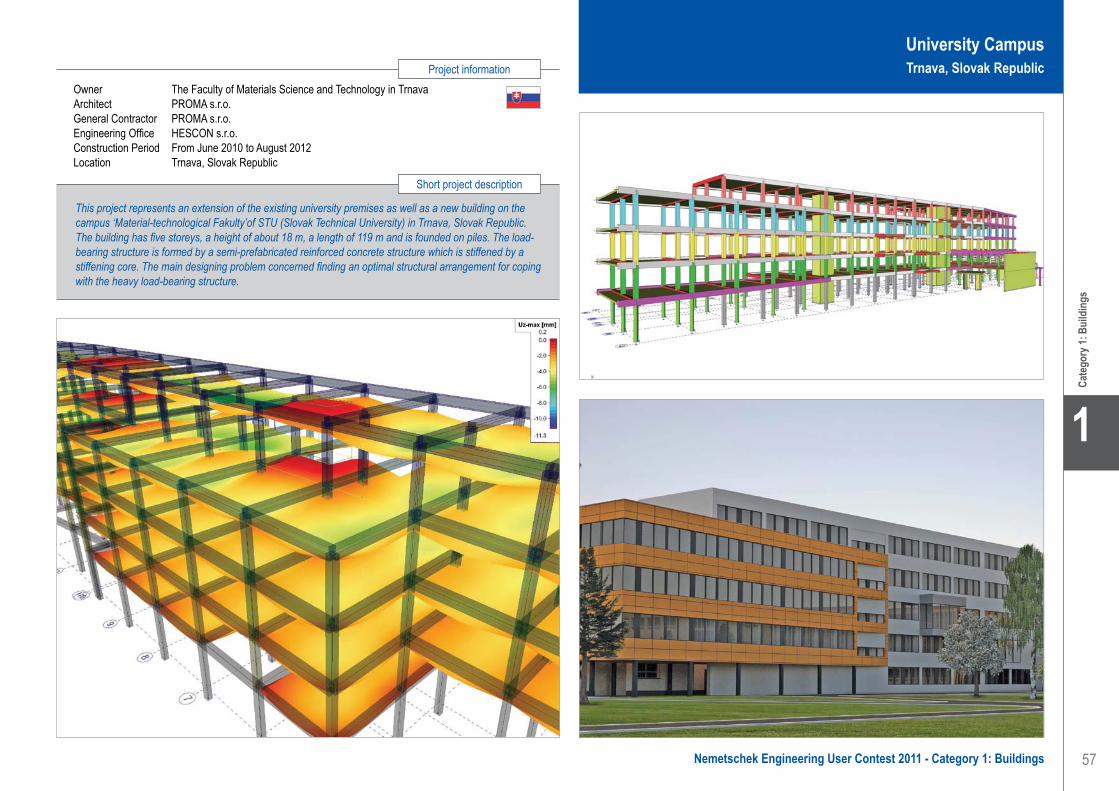
57
Project information
Short project description
Nemetschek Engineering User Contest 2011 - Category 1: Buildings
Cate
gory
1: B
uild
ings
1
University CampusTrnava, Slovak Republic
HESCON s.r.o. . . . . . . . . . . . . . . . . . . . . . . . . . . . . . . . . . . . . . . University Campus - Trnava, Slovak Republic
Owner The Faculty of Materials Science and Technology in TrnavaArchitect PROMA s.r.o.General Contractor PROMA s.r.o.Engineering Office HESCON s.r.o.Construction Period From June 2010 to August 2012Location Trnava, Slovak Republic
This project represents an extension of the existing university premises as well as a new building on the campus ‘Material-technological Fakulty’of STU (Slovak Technical University) in Trnava, Slovak Republic. The building has five storeys, a height of about 18 m, a length of 119 m and is founded on piles. The load-bearing structure is formed by a semi-prefabricated reinforced concrete structure which is stiffened by a stiffening core. The main designing problem concerned finding an optimal structural arrangement for coping with the heavy load-bearing structure.

58
1
Cate
gory
1: B
uild
ings
IGUBA, s.r.o. . . . . . . . . . . . . . . . . . . . . . . . . . . . . . . . . . . . . . . . . Thirteen-Storey Department Store - Bratislava, Slovak Republic
IGUBA, s.r.o.Contact Ivan GubaAddress Miletičova 70 82109 Bratislava, Slovak RepublicPhone +421 253416692Email [email protected]
Thirteen-Storey Department Store - Bratislava, Slovak Republic
This project presents the static calculation of the reinforced concrete structure (C30/37) for the Department Store in Bratislava - Vrakuňa, Dvojkrížna Street, Slovakia. The building will be constructed from January 2011 to May 2012. The total length of this building varies from 20.4 to 50.6 m, its width is approximately 21.4 m, the area 725 m² and the volume is more than 30.000 m³. The total volume of the reinforced concrete for the structure amounted to 4.440 m³ and its weight to 11.100 t. The building costs add up to 35.000.000 Euro.
Description of the structureThe reinforced concrete structure is composed of 13 modules 1-13, consisting of a box girder type 13-storey tower. The building has a breadth distance of 21.40 m, the expansion gap is min. 30 mm, and the overall length of the building will be 40.50 m. The supporting structure is made of cast-in-place reinforced concrete. It consists of vertical wall and horizontal board elements forming a compact unit with transversal, as well longitudinal, stiffening in horizontal and vertical planes. On the outer supporting circumferential walls there are fastened warming panels with a weight of 30 kg/m² protecting the hall from weather impacts and thermal bridges. The horizontal structures of the ceilings form monolithic plates with a thickness of 250 mm and a span of max. 7.30 m. The double-armed stairway is monolithic too. The individual parts of the structure are stiffened by monolithic circumferential walls and an internal stairway-holding wall. The main entrance with a dominant oblique monolithic roof is situated on the front shield wall.
Description of the parts of the concrete structureThe primary supporting system is combined in transversal and longitudinal direction and is calculated for every loading effect. The main focus of the static calculation is laid especially on the monolithic structure supported by circumferential walls from three sides (on the fourth side - there is a glass wall) and several supporting columns with the axial distances of max. 7.00 m and this is considered as one special unit.
The vertical and horizontal supporting structures of the building consist of monolithic plates (200 mm thick) made of concrete C30/37 which are mutually stuck. The vertical
communication areas - stairways - are situated in the stairway area limited by the internal supporting monolithic walls (200 mm thick) to approximately 5.30 x 2.60 m.
All stiffening elements are monolithic structures of the supporting system, i.e. they are designed in the longitudinal as well as in the transversal direction, in the ceiling plane monolithic wall elements and on the fourth storey also in supporting columns.
Material and loading dataThe foundation and load-bearing elements were designed according to ENV 1993-1-1:1992 Eurocode 3. The design consists of the calculation and evaluation of a number of load cases and their complex combination effect. In addition to dead load (self weight) also live load was considered: for ceilings it is the standardized value 2.50 kN/m2, for stairways 3.00 kN/m2, the snow loading (area II.) so = 0.70 kN/m2 and wind loading wo = 0.55 kN/m2 (during the erection phase and on the final building). Other types of load were seismicity 7o MSK-64, category “A” and temperature loading (during the operation the shell structure has a higher temperature than the column support).
Description of the static calculation methodThe static calculation is performed in NEXIS (ESA-Prima Win). The 80 most dangerous combinations according to ENV 1993-1-1:1992 Eurocode 3 with coefficient 1.35 in two basic combinations (load-bearing capacity and deformations) were calculated. The model contains 4.118 nodes, 1.068 bars and 1.524 1D and 2D macros.
Bearing capacity, deformations of walls and ceilingsFor the load-bearing capacity of the walls and ceilings in relevant load case combinations, the nodes were selected in all four corners of each floor. The horizontal deformation in x, y direction should not exceed 1/1.000 of the node elevation above the support according to the recommended limit deformations in ENV 1993-1-1:1992 Eurocode 3. The software evaluates extreme deformations in every direction (x, y, z) as well as maximum node rotation around the x, y, z axes separately.
Software: Nexis, Scia Engineer
The company IGUBA was established in 1997. The owner, Ivan Guba, is a static engineer who works on his own. The annual turnover amounts from 60.000 to 75.000 Euros.
Structural engineering• Civil engineering: all about static and
construction• Static design of residences and commercial
buildings• Diagnostics of bearing constructions.• Technical consulting
Some projects since 1990• Secondary Combustion Chamber & Steam
Boiler and Flue Gas Cleaning (DK)• Object of Furniture ATRIUM Bratislava (SK)• Steel Structures of many Tank- and Oil-
Stations „AVANTI“ (now SHELL) (SK, CZ, HU, AU, RO, etc.)
• Commercial building „Swietelsky“ (SK)• Technological Center E.O.S. Žilina (SK)• Hockeyball Hall Macharova Bratislava (SK)• Shopping-storing project Vajnorska (SK)• Emporia Towers Buildings in Bratislava (SK)

59
Project information
Short project description
Nemetschek Engineering User Contest 2011 - Category 1: Buildings
Cate
gory
1: B
uild
ings
1
IGUBA, s.r.o. . . . . . . . . . . . . . . . . . . . . . . . . . . . . . . . . . . . . . . . . Thirteen-Storey Department Store - Bratislava, Slovak Republic
Owner ATLAS REAL, s.r.o., BratislavaArchitect Kallay Karol, Bolčo Branislav, Valenta RadovanGeneral Contractor ATLAS REAL, s.r.o., BratislavaEngineering Office IGUBA, s.r.o., BratislavaConstruction Period From January 2011 to October 2012Location Bratislava, Slovak Republic
Thirteen-Storey Department StoreBratislava, Slovak Republic
The total length varies from 20.4 up to 50.6 m; the width is approximately 21.4 m, the surface area 725 m2 and the volume more than 30.000 m3. The total volume of reinforced concrete amounted to 4.440 m3 and its weight up to 11.100 t. The reinforced concrete structure has 13 modules 1-13, consisting of a box girder type 13-storey tower. The supporting structure is made of cast-in-place reinforced concrete. On the supporting circumferential walls there are fastened warming panels with the weight of 30 kg/m2. The main entrance with a dominant oblique monolithic roof is located on the front shield wall.

60
1
Cate
gory
1: B
uild
ings
Ingenieursbureau van der Werf en Nass BVContact Ramòn SteinsAddress Oranjeplein 98 6224 KV Maastricht, The NetherlandsPhone +31 43 3625229Email [email protected] www.werfnass.nl
Adviescentrum Rabobank - Roermond, Nederland
Het ontwerp voor het nieuwbouw adviescentrum van de Rabobank in Roermond-Herten is gemaakt door Engelman Architecten uit Roermond.
Uitgangspunt voor het ontwerp is een plastiek van kunstenaar Isamu Noguchi (Core Piece #2 basalt 1972). Het kunstwerk doet denken aan een slang die zijn hals en hoofd uitsteekt ver boven het maaiveld. Dit is vertaald door de architect naar een kantoorgebouw in twee bouwlagen met op het uiteinde een schuin naar boven stekende toren van 7 verdiepingen.
Sprekend aan het ontwerp zijn de gevelvlakken die een hoek maken met de vertikaal en de dakvlakken die een gelijke afwerking hebben als de gevel en tevens schuin geplaatst zijn.
Als we naar het gebouw kijken is de constructieve uitdaging meteen zichtbaar, niets aan het bouwwerk is recht en draagt volgens traditionele manier zijn krachten naar beneden af.
Zoals bijna standaard in de tegenwoordige tijd werd ook hier een snelle bouwtijd gevraagd vanaf het moment
dat de ontwerpfase afgesloten was. De keuze voor een opbouw van het constructieve casco uit prefab onderdelen lag dus direct voor de hand.
De onderbouw is, vanwege de benodigde voorbereidingstijd van de prefab onderdelen in het werk, uitgevoerd met behulp van ter plaatse gemaakte bekistingen en in het werk gestort beton. Dus tijdens de werkzaamheden aan de eerste bouwlaag werden in de fabriek de betonnen elementen geproduceerd.
Buiten het feit dat de vorm van het gebouw vroeg om een zeer innovatieve aanpak om te komen tot een sluitende berekening van de hoofddraagstructuur, was dit ook aan de orde voor het in de grip krijgen van de maatvoering voor de onderdelen en de samenstellingstekeningen. Voor beide probleemstellingen is er daarom voor gekozen deze aan te pakken in een virtuele 3D-omgeving.
De constructie van het hele bouwwerk is ingevoerd in een geavanceerd rekensoftwarepakket gebaseerd op de Eindige Elementen Methode (EEM). Er wordt een netwerk gemaakt van kleine elementen die ieder met hun specifieke eigenschappen rekenkundig aan elkaar geknoopt worden en hierop worden de belastingen gezet die tijdens de levensduur van het bouwwerk te verwachten zijn. Door het systeem dan door te rekenen wordt zichtbaar wat ieder element daardoor voor zijn kiezen kan krijgen. Met deze informatie wordt vervolgens in een aantal stappen gecontroleerd en eventueel aangepast totdat alle elementen in staat zijn de extreem te verwachten toestanden te weerstaan.
De vorm van het gehele constructieve casco is gemodelleerd met behulp van de software van Allplan (een 3D-tekenpakket).
Vanuit het model zijn de diverse tekeningen, die nodig zijn om zaken te produceren en om ze op de bouwplaats te kunnen samenstellen, te genereren. De op deze manier verkregen informatie geeft tevens een optimale mogelijkheid tot maatvoeringcontrole en inzichtelijkheid bij het maken van keuzes hoe en in welke volgorde de montage het best kan plaatsvinden.
Sinds 1965 heeft Ingenieursbureau van der Werf en Nass bv, Maastricht, duizenden bouw-constructies voor woningen, utiliteitsprojecten en de industrie ontworpen en berekend. Hoe groot de verschillen in uiterlijk, draagkracht en materialen ook zijn, alle constructies zijn ontworpen vanuit de filosofie dat bouwen meer is dan techniek. In dat licht, zijn constructies voor ons meer dan een optelsom van berekeningen en denken we graag vanaf het begin van het bouwproces mee over onderwerpen als milieu, gezondheid en veiligheid. Alleen zo kan een ontwerp optimaal tot ontwikkeling komen.
De creativiteit van Ingenieursbureau van der Werf en Nass bv rust op een solide basis. Onze ingenieurs zijn getrainde technici die beschikken over een gedegen kennis van materialen en rekentechnieken en een schat aan praktijkervaring. Voor het uitvoeren van hun werkzaamheden maken ze gebruik van de modernste software, waardoor ze in staat zijn ingewikkelde modellen en alternatieven snel en verantwoord door te rekenen. De tekenkamer is in 2009 overgeschakeld van 2D-tekenen naar 3D-modelleren.
Software: Allplan Engineering
Ingenieursbureau van der Werf en Nass BV . . . . . . . . . . . . . . . Rabobank Advice Centre - Roermond, The Netherlands

61
Project information
Short project description
Nemetschek Engineering User Contest 2011 - Category 1: Buildings
Cate
gory
1: B
uild
ings
1
Owner Rabobank NetherlandsArchitect Engelman ArchitectenGeneral Contractor Aannemersbedrijf Louis Scheepers RoermondEngineering Office Ingenieursbureau van der Werf en Nass BVConstruction Period From January 2010 to June 2011Location Roermond, The Netherlands
The new Rabobank advice centre building in Roermond-Herten was designed by Engelman Architecten of Roermond. The starting point for the design was a sculpture created by the artist Isamu Noguchi (Core Piece #2 basalt 1972), resembling a snake; the head and neck of which extend high above ground level. The architect translated this sculpture into an office building with two floors and a diagonally projecting tower at the end with seven floors.
Rabobank Advice CentreRoermond, The Netherlands
Ingenieursbureau van der Werf en Nass BV . . . . . . . . . . . . . . . Rabobank Advice Centre - Roermond, The Netherlands

62
1
Cate
gory
1: B
uild
ings
KÉSZ Building and Construction CompanyContact V. Császár, E. Bogatyreva, C. Lódri,
G. Molnár, J. Borbély, R. FeketeAddress Mester street 87 1095 Budapest, HungaryPhone +36 14766500Email [email protected] www.kesz.hu
Reconstruction and Extension of Ferihegy Airport - Budapest, Hungary
In 2008 the KÉSZ Building and Construction Company won the public procurement tender for the reconstruction and development works on the Budapest Airport, a strategic project for Hungary.
The most important parameters of the project and the structureThe tasks of our company included the preparation of the construction plan for the operating airport, the demolition and reconstruction of the existing terminals 2A and 2B, the general construction of the airport’s monitoring buildings, the Sky Court commercial area and landing stage B. The project includes the assembly of 52 elevators, 42 escalators, package handling technology and manufacturing and assembly of a 70 metres wide steel roof structure.
The Sky Court building will get its usage permission on 30th November 2010. We built about 7.000 m3 of concrete with about 190 tons of rebar. We drew 190 plans with the highest revision index is 8, and this just for the superstructure.
The structure was designed according the Eurocode, so we had to check the building for impacts of earthquake. Therefore the basement is just a “box”, but we divided the superstructure into 3 dilatation units.
The project approachThe deadlines were very short and our capacity was limited, so the reinforcement plans were made by a subcontractor. Our tasks were to make the formwork and the positioning as well as the detailed reinforcing plans (for example the force transmission joints of the T pillars). The requirements of the architects and of course of the customer were continuously changing. We had to be ready for a lot of issues.
The drawings were made by Allplan Engineering. We used the Modelling 3D, Views and sections, Reinforcing and the Mesh reinforcing modules. To keep immediate track of changes without mistakes, “3D modelling” was used. To get the sections, the “Views and sections” modules were extremely useful. For the reinforcement details we modelled the rebars in 3D, because the pulling force was about 2.000 kN, to resist this force we had to use a lot of rebars in order to ensure that the
joint was able to be constructed. The anchoring bars of the steel roof structure made our task even more challenging. The heads of the T pillars had no parallel planes, so all of the stirrups had different sizes.
It was essential to pay a lot of attention to calculate and construct these bars and stirrups. The design of the big span beams in unit PL3 Arrival and Departure level was also difficult. These beams had to support 2 levels, because the pillars in the Arrival levels were pulled pillars. The main reinforcing is 46Ø32. We had to investigate if the rebars of the pillar could be positioned across these bars.
The added value of the softwareAllplan Engineering made our work a lot easier.
We used the following features to make the detailing faster and more effective: • Automatic dimensioning• Region reinforcement• Welded mesh reinforcement• Compare old and new DWG• Helpful automation of Views and sections (in
dimensioning and labels)• Hot keys • Batch PDF printing (as archive)• DXF import
This project also contains a lot of steel structures and we had to check the clashes between RC and steel structures. The DXF import proved to be a great solution for this issue.
All the structures have been built with success, without serious, unsolvable constructing issues.
Please feel free to visit the construction in Hungary or have a look at the photos!
KÉSZ GroupMore than a quarter century ago KÉSZ was founded as a family enterprise; today it is a holding, which employs more than 1,300 people in Hungary and neighbouring countries; its income has reached 70 billion HUF. Through its member corporations, KÉSZ Group is present on the building construction market, building element manufacturing, property development, facility management, fleet management and last but not least, the environment industry. The KÉSZ Building and Construction Company is a member of the KÉSZ Group.
KÉSZ Building and Construction CompanyThe KÉSZ Building and Construction Company is the flagship of the KÉSZ Group. They provide full-scale services in the building industry, more precisely in general construction, design, structure building, building mechanical and electrical execution and technological erection. Among our more than 3.600.000 m2 of references we can mention industrial halls, logistic centres, power plants, offices, public buildings, stadiums, hypermarkets, shopping centres, hotels etc.
Software: Allplan Engineering
KÉSZ Building and Construction Company. . . . . . . . . . . . . . . . . Reconstruction and Extension of Ferihegy Airport - Budapest, Hungary

63
Project information
Short project description
Nemetschek Engineering User Contest 2011 - Category 1: Buildings
Cate
gory
1: B
uild
ings
1
Owner KÉSZ Building and Construction CompanyArchitect Zoltán TimaGeneral Contractor KÉSZ Building and Construction CompanyEngineering Office KÉSZ Building and Construction CompanyConstruction Period From November 2008 to November 2010Location Budapest, Hungary
The project is about the preparation of the construction plans for the Budapest airport, including the demolition and reconstruction of the existing terminals 2A and 2B, the general construction of the monitoring buildings, the Sky Court commercial area, as well as landing stage B. It includes the assembly of 52 elevators, 42 escalators, package handling technology and manufacturing and assembly of the 70 meter wide steel roof structure. We used about 7.000 m3 of reinforced concrete and more than a thousand tons of steel.
Reconstruction and Extension of Ferihegy AirportBudapest, Hungary
KÉSZ Building and Construction Company. . . . . . . . . . . . . . . . . Reconstruction and Extension of Ferihegy Airport - Budapest, Hungary

64
1
Cate
gory
1: B
uild
ings
Konstruktieburo Snetselaar BVContact Jan van KlinkenAddress Galileilaan 36 6716 BP EDE, The NetherlandsPhone +31 318 62 71 62Email [email protected] www.snetselaar.nl
Food & Facility Center Wetering Noord - Utrecht, Nederland
Het Food & Facility Center Wetering Noord in Utrecht is een gebouw met een bijzondere plattegrond. De plattegrond van het gebouw bestaat uit een ellips met een afmeting van ca. 55 bij 40 meter. Het gebouw bestaat uit drie bouwlagen en huisvest diverse restaurants en andere horecabedrijven.De hoofddraagconstructie van het gebouw is door hoofdaannemer Bruil Bouwbedrijf Ede BV volledig uitgevoerd in in het werk gestort beton. De engineering van de betonconstructie is uitgevoerd door Konstruktieburo Snetselaar BV uit Ede.
KolommenplanDe verticale draagconstructie van het Food & Facility Center bestaat uit een regelmatig patroon van betonkolommen. In het hart van de ellips zijn 4 centrale middenkolommen rond 500 mm h.o.h. 6.7 meter in één lijn aanwezig. Om deze centrale kolommen bevindt zich een ellipsvorming patroon van 18 middenkolommen rond 500 op een afstand van 8.3 tot 10.9 m. Een derde rij kolommen bestaat uit 40 kolommen rond 350 mm evenwijdig aan de middenkolommen op 8.3 meter afstand. Het regelmatige kolommenplan wordt op twee plaatsen onderbroken om plaats te bieden aan de liftschachten.
Over de breedste zijde van de ellips (horizontale as) is de totale afstand tussen de buitenste kolommen ca. 53.4 meter. Over de smalste zijde van de ellips (verticale as) is deze afstand 38.4 meter.
ConstructieDe vloerrand van de eerste en tweede verdiepingsvloer vormt een overstek van 3.2 meter voorbij de buitenste kolommenrij. Het overstek van de vloerrand komt ook over een gedeelte terug in de dakvloer.Bij de entree van het gebouw is een vide aanwezig in de eerste en tweede verdiepingsvloer. De gevelkolommen lopen door tot aan de dakvloer en zijn uitgevoerd in stalen buiskolommen rond 355 x 10 mm.
De stabiliteit van het gebouw wordt geleverd door alle betonkolommen. Door de gunstige verdeling van de windbelasting en de normaalkracht over de kolommen is dit goed te realiseren. Voor de meeste kolommen bleek dan ook de sterkte en niet de stijfheid maatgevend te zijn voor de dimensionering.
VloerwapeningDe vloeren zijn 350 mm dik en worden puntvorming ondersteund. Door de gunstige verhouding van de veldoverspanningen bleek een ondernet rond 12-150 bijna overal toereikend te zijn. De bovenwapening boven de middenkolommen en centrale kolommen liep op tot ca. 2000 mm²/m. De vloerwapening is met Scia Engineer berekend. Vanwege de ronde vorm van het gebouw zijn de in het werk gestorte vloeren traditioneel uitgekist.
PonswapeningHet toepassen van de ponswapening is een tijdrovende bezigheid en dient zo veel mogelijk te worden voorkomen. Voor de gevelkolommen rond 350 is gekozen om de betonkwaliteit te verhogen naar C28/35 met een beperkte hoeveelheid bijlegwapening boven de kolommen.
Boven de kolomen rond 500 is wel ponswapening toegepast. Hier is gekozen voor dwarskrachtrekken. Een dwarskrachtrek bestaat uit (verticale) ponswapening welke door middel van constructieve lassen verankerd is aan horizontale boven- en onder staven. Het voordeel van het prefab dwarskrachtrek is dat de ponswapening volledig tussen het onder- en bovennet ligt. In goed overleg met de betrokken partijen waaronder de hoofdconstructeur en de gemeente Utrecht is het dwarskrachtrek met succes toegepast.
EvaluatieHet Food & Facility Center Wetering Noord is een project waarbij op meerdere punten de uitdaging is aangegaan om creatief en innovatief bezig te zijn. De software van Scia Engineer heeft hierin een positieve bijdrage geleverd.
Konstruktieburo Snetselaar BV is een landelijk opererend onafhankelijk en zelfstandig adviesbureau voor bouwconstructies. Onze activiteiten bestaan uit het ontwerpen, berekenen en tekenen van bouwkundige en civiele constructies van gewapend/voorgespannen beton, staal en hout. De bouwsectoren waar wij ons op richten zijn de utiliteits- en woningbouw alsook de industriële bouw en de droge infrastructuur.
Onze praktijkgerichte aanpak is gebaseerd op de betrokkenheid van onze medewerkers bij zowel
het voortraject als de uitvoering van projecten.Meedenken tijdens het bouwen staat voorop. Ons bureau kenmerkt zich door snelle prijsbewuste adviezen met korte lijnen naar de opdrachtgever, waarbij persoonlijke contacten zeer belangrijk zijn.
Met ons team bieden we een breed pakket van diensten aan, waaronder:• Alle werkzaamheden als hoofdconstructeur• Funderingsberekeningen en -adviezen• Werkplaatstekeningen staalconstructies• Engineering prefab betonconstructies
Software: Scia Engineer
Konstruktieburo Snetselaar BV . . . . . . . . . . . . . . . . . . . . . . . . . . Food & Facility Center Wetering Noord - Utrecht, The Netherlands
My

65
Project information
Short project description
Nemetschek Engineering User Contest 2011 - Category 1: Buildings
Cate
gory
1: B
uild
ings
1
Owner A2 Wetering Noord BVArchitect Verheijen - Smeets architecten bvGeneral Contractor Bruil Bouwbedrijf Ede BV Engineering Office Konstruktieburo Snetselaar BVConstruction Period From April 2009 to December 2009Location Utrecht, The Netherlands
The Food & Facility Center Wetering Noord in Utrecht consists of three floors and houses, several restaurants and other catering establishments. The main load bearing structure of the building is fully implemented in in-situ concrete. The engineering of the concrete construction is carried out by Konstruktieburo Snetselaar BV. The floor reinforcement is calculated with Scia Engineer.The food & Facility Center Wetering Noord is a project involving several creative and innovative challenges. Scia Engineer software has made a positive contribution.
Food & Facility Center Wetering NoordUtrecht, The Netherlands
Konstruktieburo Snetselaar BV . . . . . . . . . . . . . . . . . . . . . . . . . . Food & Facility Center Wetering Noord - Utrecht, The Netherlands
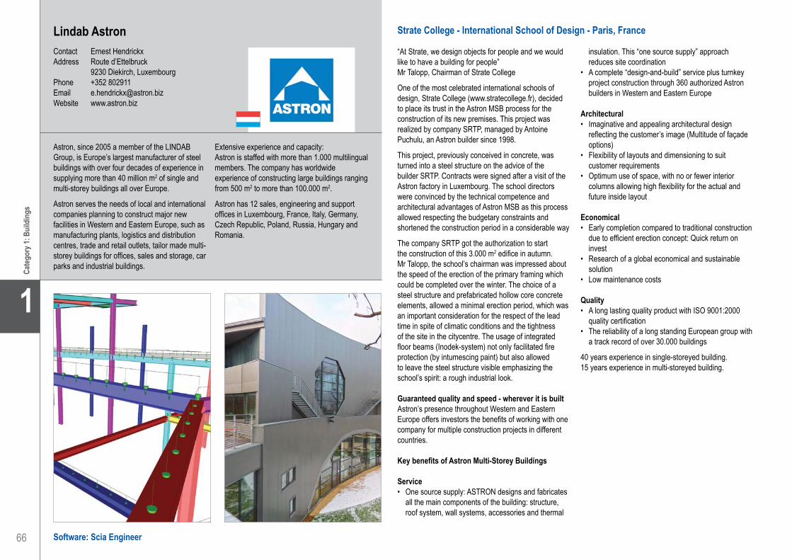
66
1
Cate
gory
1: B
uild
ings
Lindab AstronContact Ernest HendrickxAddress Route d’Ettelbruck 9230 Diekirch, LuxembourgPhone +352 802911Email [email protected] www.astron.biz
Strate College - International School of Design - Paris, France
“At Strate, we design objects for people and we would like to have a building for people”Mr Talopp, Chairman of Strate College
One of the most celebrated international schools of design, Strate College (www.stratecollege.fr), decided to place its trust in the Astron MSB process for the construction of its new premises. This project was realized by company SRTP, managed by Antoine Puchulu, an Astron builder since 1998.
This project, previously conceived in concrete, was turned into a steel structure on the advice of the builder SRTP. Contracts were signed after a visit of the Astron factory in Luxembourg. The school directors were convinced by the technical competence and architectural advantages of Astron MSB as this process allowed respecting the budgetary constraints and shortened the construction period in a considerable way
The company SRTP got the authorization to start the construction of this 3.000 m2 edifice in autumn. Mr Talopp, the school’s chairman was impressed about the speed of the erection of the primary framing which could be completed over the winter. The choice of a steel structure and prefabricated hollow core concrete elements, allowed a minimal erection period, which was an important consideration for the respect of the lead time in spite of climatic conditions and the tightness of the site in the citycentre. The usage of integrated floor beams (Inodek-system) not only facilitated fire protection (by intumescing paint) but also allowed to leave the steel structure visible emphasizing the school’s spirit: a rough industrial look.
Guaranteed quality and speed - wherever it is builtAstron’s presence throughout Western and Eastern Europe offers investors the benefits of working with one company for multiple construction projects in different countries.
Key benefits of Astron Multi-Storey Buildings
Service• One source supply: ASTRON designs and fabricates
all the main components of the building: structure, roof system, wall systems, accessories and thermal
insulation. This “one source supply” approach reduces site coordination
• A complete “design-and-build” service plus turnkey project construction through 360 authorized Astron builders in Western and Eastern Europe
Architectural • Imaginative and appealing architectural design
reflecting the customer’s image (Multitude of façade options)
• Flexibility of layouts and dimensioning to suit customer requirements
• Optimum use of space, with no or fewer interior columns allowing high flexibility for the actual and future inside layout
Economical• Early completion compared to traditional construction
due to efficient erection concept: Quick return on invest
• Research of a global economical and sustainable solution
• Low maintenance costs
Quality• A long lasting quality product with ISO 9001:2000
quality certification• The reliability of a long standing European group with
a track record of over 30.000 buildings
40 years experience in single-storeyed building.15 years experience in multi-storeyed building.
Astron, since 2005 a member of the LINDAB Group, is Europe’s largest manufacturer of steel buildings with over four decades of experience in supplying more than 40 million m2 of single and multi-storey buildings all over Europe.
Astron serves the needs of local and international companies planning to construct major new facilities in Western and Eastern Europe, such as manufacturing plants, logistics and distribution centres, trade and retail outlets, tailor made multi-storey buildings for offices, sales and storage, car parks and industrial buildings.
Extensive experience and capacity:Astron is staffed with more than 1.000 multilingual members. The company has worldwide experience of constructing large buildings ranging from 500 m2 to more than 100.000 m2.
Astron has 12 sales, engineering and support offices in Luxembourg, France, Italy, Germany, Czech Republic, Poland, Russia, Hungary and Romania.
Software: Scia Engineer
Lindab Astron. . . . . . . . . . . . . . . . . . . . . . . . . . . . . . . . . . . . . . . . Strate College - International School of Design - Paris, France

67
Project information
Short project description
Nemetschek Engineering User Contest 2011 - Category 1: Buildings
Cate
gory
1: B
uild
ings
1
Owner Strate CollegeArchitect Mr Bruno PingeotGeneral Contractor S.R.T.P.Engineering Office Lindab Astron - MSBConstruction Period From December 2007 to September 2009Location Paris, France
The international School of Design (and the company “Digital Packaging”) overlooks Paris and the Eiffel Tower from the top of its four levels. Six hundred persons, of whom four hundred are students, bring life to this assembly whose internationally recognized expertise is going to deliver the future designers. The choice of a steel structure and prefabricated hollow core concrete elements, allowed a minimal erection period, which was an important consideration for the respect of the lead time in spite of climatic conditions and the tightness of the site in the city-centre.
Strate College - International School of DesignParis, France
Lindab Astron. . . . . . . . . . . . . . . . . . . . . . . . . . . . . . . . . . . . . . . . Strate College - International School of Design - Paris, France
My

68
1
Cate
gory
1: B
uild
ings
Melliss LLP . . . . . . . . . . . . . . . . . . . . . . . . . . . . . . . . . . . . . . . . . Botwell Green Sports and Leisure Centre - London, United Kingdom
Software: Scia Engineer
Melliss LLPContact Robert Frost, Nick Antal, Ruslan KoutlukaevAddress Boundary House, The Pines Business Park Broad Street, Guildford, Surrey GU3 3BH Guildford, United KingdomPhone +44 1483567879Email [email protected] www.melliss.com
Botwell Green Sports and Leisure Centre - London, United Kingdom
The initial brief included the construction of a swimming pool area with plant rooms and viewing galleries, a semi-circular two storey fitness suite area with aerobics studio, community areas and changing village, and a library area with parking and a sports hall. The building was constructed to provide community and leisure facilities to Hayes.
The building was U-shaped in plan to be sympathetic to the existing landscaping. The pool and the library areas were designed as independent frames comprising 30 m glulam rafters over the pool, 20 m curved cellular rafters over the sports hall, 8.4 m trusses to the side of the plant room and a complex arrangement of the roof plan bracing trusses over the fitness suite and the library areas. The pools and the basement were in-situ concrete with permanent perimeter sheet piling. To improve buildability, the viewing galleries were designed as 8.4 m precast Z-planks supported by steel columns and beams to the side of the plant room.
During construction, the design team was instructed to add a gymnasium, which had to be sited between the pool and the library areas. The erection of the superstructure to the original scheme was already complete prior to the commencement of the gymnasium, which therefore had to be fully independent.
The ChallengeThe major technical challenge was to build new foundations next to the pool basement. To avoid surcharging the basement during piling, the closest line of CFA piles had to be bored at least 4.5 m from the building. The main column line was set out at 3 m from the pool area and was supported by cantilevering foundation beams. The minor column line at 0.5 m from the pool area and part of the ground floor slab were supported by the sheet piled wall.
Gas contamination on site necessitated the use of ventilation and a gas membrane under the entire building. The erection of the gymnasium was phased in three stages: foundations, superstructure and the ground floor slab. 3D structural analysis of the slab and foundations was carried out using Scia Engineer for both the construction stage and permanent condition
to ensure that the cantilevering foundations were effectively tied back avoiding any uplift.
Simulation of the foundation’s behaviour during construction phases was the modelling challenge. As the construction stage analysis is not a usual service in the company’s scope of works, the associated modules were not in the supplied program package. The solution was found in the application of the Absences: the ground floor slab and the third phase ground beams were associated with an absence group and were excluded from load combinations created for the construction stage.
The ground floor slab was modelled at a level higher than the first phase foundation beams and was linked with the latter using plate elements with edge hinges representing the gas membrane and allowing the transfer of vertical loads only. The third phase ground beams, integral with the slab, were isolated from link elements using beam end hinges and connected to foundation corbels using rigid arms. Slab hinges were used extensively throughout to model slab joints. Such an approach has aided more accurate simulation of the structure and reduction of building costs: the slab thickness was reduced from 350 mm to 300 mm, the depth of foundation beams was reduced from 1100 mm to 900 mm, etc.
Use of Scia EngineerScia Engineer was used throughout the project for modelling various building structures and, as a value engineering tool, allowed construction costs to reduce which would not have been possible using hand calculations or non-FE software programs.
Melliss was formed in 1878 by J.C. Melliss, a former Royal Engineer Officer and part of the Melliss family that are synonymous with St. Helena.
Until the 1960’s the firm was responsible for mainly civil engineering works, especially water towers and supplies in London and Norfolk.During WWII, Melliss was involved in the PLUTO (Pipe Line Under The Ocean) project.
From the 1960’s onwards Melliss have increased the structural content of its work and have been involved in a variety of building projects.
Melliss offer a broad range of Structural Engineering services and have a broad experience of working on multi million pound projects.
In our commitment to quality improvement, we are constantly training our staff, and using advanced 3D modelling software coupled with extensive knowledge of communication technology to ensure information is shared throughout the design team.

69
Project information
Short project description
Nemetschek Engineering User Contest 2011 - Category 1: Buildings
Cate
gory
1: B
uild
ings
1
Melliss LLP . . . . . . . . . . . . . . . . . . . . . . . . . . . . . . . . . . . . . . . . . Botwell Green Sports and Leisure Centre - London, United Kingdom
Botwell Green Sports and Leisure CentreLondon, United Kingdom
Owner London Borough of HillingdonArchitect Burke RickhardsGeneral Contractor GB Building Solutions LtdEngineering Office Melliss LLPConstruction Period From May 2008 to May 2010Location London UB3, United Kingdom
The project is situated in West London, and is a £20M recreation complex offering state-of-the-art facilities, including a National Standard Gymnasium, a 25 m competition pool, a leisure pool, a spacious gym suite with aerobics studios, multipurpose sports hall, community meeting areas and the library. The Centre involved various types of construction, including reinforced in-situ and precast concrete, steel and composite, Glulam timber and masonry. Scia Engineer was used to model various parts of the building, including foundations of the Gymnasium integrated with the ground floor construction.

70
1
Cate
gory
1: B
uild
ings
Sailer Stepan und Partner GmbHContact Stefan M. SchmidtAddress Ingolstädter Straße 20 80807 München, GermanyPhone +49 893509040Email [email protected] www.ssp-muc.com
Hochschule für Fernsehen und Film mit Ägyptisches Museum - München, Deutschland
Das Gebäude gliedert sich in einen 150 m langen, achtgeschossigen Gebäuderiegel für die Filmhochschule mit Kino- und Hörsaalanbauten, einen vorgelagerten unterirdischen Museumsbau sowie eine Tiefgarage.
Das Gebäude wurde als fugenlose Stahlbeton- bzw. Stahlbetonverbundkonstruktion konzipiert. Zwei Untergeschosse liegen im Grundwasser. Große Räume im Sichtbetonsockel werden darüber mit dreigeschossigen Verbundfachwerken entlang der Flurwände mit Spannweiten bis zu 30 m stützenfrei überbrückt.
FilmhochschuleDie Hochschule für Fernsehen und Film ist im Sichtbetonsockel mit aufgesetztem Glaskörper untergebracht. Sie wird über das östlich gelegene, stützenfreie Foyer erschlossen. Die mit einer doppelschaligen Glasfassade versehenen Obergeschosse enthalten die kleinteiligen Räume mit Büro- und Einzelstudionutzung. Besonders auffällig sind hier die Längsfachwerke in Stahlverbundbauweise, die in den Flurzonen über drei Geschosse mit Spannweiten bis zu 30 m angelegt sind. Die Stahlbetondecken sind integraler Bestandteil dieser Fachwerke, die die darunter im nahezu fensterlosen Betonsockel liegenden Kinosäle, Vorlesungsräume, Cafeteria, Bibliothek und Foyer ohne störende Stützen erst ermöglichen.
Auf Wunsch des Architekten wurde dieser Sockel in Sichtbeton mit rotem Porphyr als Zuschlagstoff versehen sowie in Lagen abwechselnd naturgrau oder gelb eingefärbt und anschließend von Steinmetzen gestockt. Das Ergebnis vermittelt in seiner gewollt unregelmäßigen Erscheinung auf wunderbare Weise einen Naturstein, der farblich mit der gegenüber liegenden Alten Pinakothek korrespondiert. Die Herstellung der Sockelwände erfolgte in bis zu 90 m langen Betonierabschnitten unter Verwendung einer Kletterschalung. Die daran anschließenden Decken wurden über Bewehrungsanschlüsse nachträglich eingefügt, d.h. viele Wände wurden zwei- bis dreigeschossig hergestellt. Die Arbeitsfugen dieser Sichtbetonwände wurden minimiert und verdeckt angeordnet.
Staatliches Museum für Ägyptische KunstEine große Portalwand aus gelb eingefärbtem, ebenfalls gestocktem Sichtbeton markiert den westlich gelegenen Eingang des Museums. Eine Freitreppe führt zur abgesenkten Museumsebene und assoziiert so den engen Eingang einer ägyptischen Ausgrabungsstätte. Die unterirdischen Ausstellungshallen präsentieren sich einschließlich der Großvitrinen in schwarz pigmentiertem Sichtbeton ohne erkennbare Arbeitsfugen. Die natürliche Belichtung einiger Räume erfolgt über einen lang gestreckten, von dreieckigen Stützen eingefassten Atriumshof. Die gesamte Versorgungstechnik liegt versteckt in den Hohlkammerdecken, den Innenwänden und Bodenplatten.
Der unterirdische Baukörper liegt bis zu vier Meter im Grundwasser und wurde auf Wunsch des Bauherrn für die hochwertige Museumsnutzung als kombinierte „Schwarz-Weiße Wanne“ ausgebildet, d.h. die Außenbauteile aus Beton mit hohem Wassereindringwiderstand und zugehöriger, die Rissbreiten beschränkenden Bewehrung erhielten zusätzlich eine Folienabdichtung.
TiefgarageDie konventionelle Stahlbetonkonstruktion mit Flachdecke schließt fugenlos an das Sockelgebäude an und wird von den drei Anbauten mit Audimax, Werkstätten und weiteren Verwaltungseinheiten überbaut.
Baugrube und AbbruchDie Planungsleistungen umfassten außerdem die statische Betreuung der Abbrucharbeiten der mathematischen Institute der TUM und die darunter gelegenen Bunker der nicht mehr verwirklichten Reichskanzlei sowie Entwurf und Genehmigungsplanung der Baugrubenumschließung und die Sanierung bzw. Unterfangung des verbliebenen Rechenzentrums.
Das Ingenieurbüro Sailer Stepan und Partner GmbH wurde 1954 gegründet. Seither erbringen wir vielfältige und anspruchsvolle Planungsleistungen auf höchstem Niveau.
Unsere Tätigkeit deckt alle Grundleistungen der HOAI und nahezu alle besonderen Leistungen ab. Sie erstreckt sich auf die Planung von Neubauten, Umbauten und denkmalgeschützter Bauwerke, sowie auf Gutachten und Machbarkeitsstudien.
Die Bearbeitung eines Wanddurchbruches ist ebenso Bestandteil unseres Leistungsspektrums
wie die der Tragkonstruktion eines Groß-Bauvorhabens.
Unsere Zielsetzung ist die Entwicklung, Planung und Berechnung optimierter Tragwerke durch frühzeitige und umfassende Beratung in Abstimmung mit den Planungsbeteiligten. Architektonischer Anspruch, Wirtschaftlichkeit, Funktionalität und Innovation sind wesentliche Kriterien unserer Planung.
Software: Allplan Engineering
Sailer Stepan und Partner GmbH . . . . . . . . . . . . . . . . . . . . . . . . Film and Television College and Egyptian Museum - Munich, Germany

71
Project information
Short project description
Nemetschek Engineering User Contest 2011 - Category 1: Buildings
Cate
gory
1: B
uild
ings
1
Owner Freistaat BayernArchitect Peter Böhm ArchitektenGeneral Contractor Universitätsbauamt MünchenEngineering Office Sailer Stepan und Partner GmbHConstruction Period From March 2008 to July 2011Location Munich, Germany
The project regards the College for Television and Film as well as the Federal Museum for Egyptian Art in Munich. It consists of a 150 m long, eight-storey building for the film college with cinemas and lecture halls connected on the side and an underground museum. The structure is conceived as a reinforced concrete and composite construction frame without expansion joints. Two three-storey trusses along the corridor walls act as transfer structures over the studios and the foyer area.
Television and Film College and Egyptian MuseumMunich, Germany
Sailer Stepan und Partner GmbH . . . . . . . . . . . . . . . . . . . . . . . . Film and Television College and Egyptian Museum - Munich, Germany

72
1
Cate
gory
1: B
uild
ings
Software: Scia Engineer
Sancha SAContact Martin DavidAddress Route de Neuchâtel 42 1401 Yverdon-Les-Bains, SwitzerlandPhone +41 24 424 82 00Email [email protected] www.sancha.ch
Maison de la Paix - Genève, Suisse
Le propriétaire est l’Institut des Hautes Etudes Internationales et du Développement (IHEID).La Maison de la paix s’élèvera sur un terrain situé entre le chemin Rigot et la voie ferrée. Son cœur architectural sera composé d’une bibliothèque, d’auditoires et de salles de cours, ainsi que d’une cafétéria. Les bureaux seront disposés de manière à encourager la circulation des personnes et des idées au sein de l’Institut ainsi qu’entre celui-ci et les institutions partenaires.
Description de la construction La structure portante du bâtiment est en acier de qualité S355, les porteurs verticaux sont constitués de poteaux ronds ROR 323.9*25 et de ROR 323.9*40 ; certains de ces poteaux sont remplis de béton pour des questions de sécurité au feu. Les autres éléments porteurs verticaux sont des murs et des voiles en béton armé réalisés aux -2 et -1 en béton étanche à fissuration contrôlée de qualité C30/37 et ailleurs (cage d’escalier) en béton standard de qualité C30/37. Les contreventements parasismiques sont assurés par des croix de St-André en HEM 300 disposées proche des cages d’escaliers, par les diagonales des façades et par les murs parasismiques en béton armé disposés dans les cages d’escaliers. Tous ces éléments porteurs verticaux reposent sur un radier à fissuration contrôlée de 25 cm d’épaisseur et de qualité C30/37 avec des sur-profondeurs ponctuelles qui permettent de transmettre les efforts directement aux pieux qui se trouvent juste dessous. Les fondations de la Maison de la Paix sont constituées principalement de fondations profondes de type pieux foré tubé. Les pieux sont dimensionnés comme des pieux colonnes appuyés au sein d’horizons compétents de la molasse. Un encastrement minimal de 3 diamètres dans la molasse est considéré de sorte à garantir l’arrêt du pieux dans une couche de caractéristiques mécaniques suffisantes de type gréseuse éventuellement silteuse. Le béton constituant les types de pieux sera de type C30/37 XA2.
Une structure tridimensionnelle disposée de manière rayonnante dans le plan sur l’auditoire de la feuille 1 est composée de plusieurs poutres à treillis d’une hauteur statique de 2 m qui permet de reprendre les charges verticales transmises par les poteaux du noyau
central de la feuille 1 et de les ramener aux porteurs périphériques.
Les éléments porteurs horizontaux sont constitués de dalles massives en béton armé d’une épaisseur de 35 cm et de qualité C30/37. Certaines dalles sont précontraintes pour permettre de franchir les grandes portées de 12 à 15 m. Les dispositifs anti-poinçonnement font partie de la structure métallique sous forme de croix autour des poteaux. Des HEM 260, intégrés et connectés par des goujons à l’intérieur des dalles situés en périphéries des feuilles, constituent les membrures horizontales des poutres à treillis de façades qui permettent de libérer de grand espace sous la façade de la feuille 1 et de la feuille 4. Ces membrures horizontales sont connectées par des diagonales ROR 323.9*25 et 323.9*40. Tous les assemblages sont soudés sur place.
Les volées d’escaliers sont en béton préfabriqués sauf ceux de la feuille 4 et de la sortie de secours Sud (feuille 1) qui constituent des éléments de raidisseurs des murs.
Les escaliers hélicoïdaux situés à l’intérieur des puits de lumières de la feuille 1 sont en béton armé coulé sur place.La déformation maximum du porte-à-faux de la feuille 1 ainsi que de la grande façade de la feuille 4 à absorber par les détails de fixations des façades vitrées est de 50 mm.
Le calcul statique effectué sur le modèle 3D du bâtiment a servi au dimensionnement des structures métalliques (contrôle acier) et des dalles et voiles en béton armé. En outre, un calcul dynamique a été généré par le logiciel, ce qui a conduit à interdire certaines zones sensibles du bâtiment à des sollicitations cycliques dues à des groupes de personnes qui font de la danse ou gymnastique rythmée ainsi que des militaires marchant au pas ou toute autre activité qui sort du cadre d’une utilisation de bureau, salle de classe ou de conférence.
Un calcul au feu naturel, selon simulation numérique a permis d’éviter de protéger toutes les parties de la structure métallique. La résistance structurelle requise est de R60.
Le bureau d’ingénieries civiles Sancha SA, est né en décembre 1988. Aujourd’hui, deux jeunes associés ont rejoint la direction et le bureau compte 14 collaborateurs.
Passionnés des structures nous sommes actif dans les milieux du dimensionnement des structures en béton armé et précontraint, structures en bois et structures métalliques. Notre but est de rechercher des solutions afin de répondre aux lignes directrices architecturales dans le respect des contraintes du bon comportement des structures à long terme.
Notre objectif est d’avoir toujours l’énergie pour se remettre en question afin de ne pas sombrer dans les acquis mais aux contraires chercher sans relâche à se perfectionner et à apporter de nouvelles idées de conception.
Sancha SA. . . . . . . . . . . . . . . . . . . . . . . . . . . . . . . . . . . . . . . . . . House of Peace - Geneva, Switzerland

73
Project information
Short project description
Nemetschek Engineering User Contest 2011 - Category 1: Buildings
Cate
gory
1: B
uild
ings
1
Owner IHEIDArchitect IPAS General Contractor IHEIDEngineering Office Sancha SAConstruction Period From May 2011 to 2013Location Geneva, Switzerland
The ‘Maison de la Paix’ is a new building in Geneva, bringing together different centers in the area of international peace and security in one location. At its heart will be a library, auditoriums and seminar rooms, and a cafeteria. The offices will be positioned in a manner which facilitates interaction of people and ideas within the Institute as well as with partner institutions. The steel structure that carries the concrete decks allows for wide open spaces. The building has been designed towards seismic actions and under fire conditions. Specific aspects of the dynamic behaviour have also been considered at serviceability state.
House of PeaceGeneva, Switzerland
Sancha SA. . . . . . . . . . . . . . . . . . . . . . . . . . . . . . . . . . . . . . . . . . House of Peace - Geneva, Switzerland

74
1
Cate
gory
1: B
uild
ings
Software: Scia Engineer
TE, Consulting Engineer . . . . . . . . . . . . . . . . . . . . . . . . . . . . . . . Extension of Single-Floor Shop - Chania, Greece
TE, Consulting EngineerContact Eleftherios TsolakisAddress Soudas Av. 23, Crete, Chania 73200 Chania, GreecePhone +30 2821081846Email [email protected] www.etsolakis.gr
Extension of Single-Floor Shop - Chania, Greece
Introduction to the projectThe project included the extension of an old single-floor shop, made out of concrete in 1984. The free acreage was limited because an avenue passed through the land few years ago.
Description of the projectThe geometry of the floor plan of the extension is trapezoid. The large side is 9.25 meter, the narrow side 7.90 meter and the length about 29.20 meter. The height of the structure is about 4.30 meter. The access for the cranes to the land was easy through the main avenue.
ApproachThe owner wanted the old building and the extension to be as one shop. He wanted the construction to be finished fast in order to be able to rent the place. We suggested a steel structure to reduce the cost and save time. In our design, we put a steel frame near the old concrete columns. The distances between the old columns were not equal. We used HEA200 cross-
sections for the columns, IPE270 for the beams, IPE160 for the purlins and SHS for the wall and the roof bracing.
The use of Scia Engineer for this projectWe measured all the dimensions of the old building and we designed the building in dwg format. The next step was to import the dwg drawing in Scia Engineer. After that, at which we used the line grid and the spans options, we started the 3D model.
The model was finished in no time. The next step was to make all the load cases, the load groups and the load combinations.
Load groups1. G : permanent 2. S : snow3. W : wind4. E : seismic
Load cases1. LC1 : self weight2. LC2 : panel’s weight3. LC3 : snow4. LC4 : seismic Y5. LC5 : seismic X6. LC6 : wind X+7. LC7 : wind X-8. LC8 : wind Y9. LC9 : wind roof
Load Combinations1. EN-ULS2. EN-SLS3. EN-seismic X4. EN-seismic Y
We used “line force” on beam for the wind and the snow loads according to the Greek ‘Actions Code’.
After the linear and the modal analysis we made section and unity checks for all the members. We also proceeded to the serviceability check for the main beams.
Scia Engineer’s Autodesign feature was used to reduce the cost of the construction.
TE, Consulting Engineer was founded in 2007 to provide the following Civil Engineering Services:• Technical advice for the development of new
buildings.• Technical advice for the restoration-upgrading
of existing buildings.• Structural design of new buildings (concrete,
steel, composite, timber and masonry structures).
• Structural design and assessment of existing buildings.
• Supervision of civil engineering works.
Thanks to our experience and our knowledge, we can accomplish even the most exacting projects.
TE, Consulting Engineer has managed over 50 projects in Greece.

75
Project information
Short project description
Nemetschek Engineering User Contest 2011 - Category 1: Buildings
Cate
gory
1: B
uild
ings
1
TE, Consulting Engineer . . . . . . . . . . . . . . . . . . . . . . . . . . . . . . . Extension of Single-Floor Shop - Chania, Greece
Owner Helen and Dimitra LafataArchitect Stefanaki Kalliopi, Tsolakis EleftheriosGeneral Contractor MorfometalEngineering Office TE, Consulting Engineer Construction Period From June 2010 to August 2010Location Chania, Greece
This project includes the extension of an old single-floor shop on the island of Crete. The geometry of the floor plan of the extension was trapezoid and the columns were not positioned at equal distances. A 3D model was designed in Scia Engineer, this for specific studies regarding the seismic design of the building. Wind and snow loads have also been calculated according to the Greek ‘Actions Code’.
Extension of Single-Floor ShopChania, Greece

76
1
Cate
gory
1: B
uild
ings
Software: Scia Engineer
Broadwater Farm and Learning Campus - London, United Kingdom
The project is situated along the northern side of Adams Road within the Tottenham district of London.The site is rectangular measuring approximately 45 m by 20 m. The main two-storeyed section of the building consists of three approximately area equal wings. The building is being built in two phases with a 50/50 split. The construction of phase 1 is about 40% complete.
Description of the projectThe school building has been designed as a two storey RC frame with the floor and roof slabs designed as 300 mm thick flat slabs. The vertical loadings are transferred to foundations through a system of RC columns and shear walls. The span of the slabs varies from 4 m up to 8 m.
With the building being erected in two phases, a construction joint has been incorporated, running through middle of the intermediate wing. The detailing of the construction joint allows for the transfer of vertical and horizontal forces from one part of the building to the other.
The three wings of the building are separated by movement joints, which allow for differential horizontal movement between each part. The detailing of the movement joints allows for the transfer of vertical forces from one part to other.
The lateral stability of the building in phase 1 is provided by a system of RC shear walls, and has been calculated with each wing being treated as an independent structure. In phase 2, the stability of the third wing is provided by a mixed system of RC shear walls and sway frames with moment connections between the columns and the slabs.
There is a mixture of cladding/finishes to the building such as glazed canopies, a link between the existing building and new building, and projecting windows which has the required structural steel framing to be integrated with the RC frame. An interesting visual effect has been created by the ‘brise soleil’ shading elements, this is a vertical system of panels to the front elevation and horizontal shading panels for doors and windows. The steel structure for these was also designed by Thomasons.
In the intermediate wing at ground floor level, there is a swimming pool. This has been formed using an in situ RC box to form the main pool structure below ground level. The ground floor slab has been designed as a RC flat slab supported on piles and pile caps.
ApproachThere were many challenges that were faced during the design of the building, these include the following:• There were many mechanical and electrical service
routes that had to be incorporated in the structure at all levels. Therefore a single 3D model for the building was required so that pile reactions could be accurately calculated.
• Calculation of long term creep deflections were difficult to calculate manually due to the unequal spans of the slabs. Scia Engineer was very beneficial in assessing creep and this was found to be the governing design criteria.
• Analysis of slab openings to determine reinforcement requirements.
• Assessing the lateral stability of building using frame action and shear walls system.
• Steel frame canopies and links were designed as sway frame structures.
The use of Scia EngineerThe Scia Engineer software was very useful as we were able to calculate accurate pile loads, calculate the internal forces in elements and determine reinforcement requirements. Especially important were results of the long term slab deflections which were governing for this project.
The software also enabled us to quickly incorporate changes proposed by the Architect and Services Engineers and see how changes affected our design.
The visualisation tools in the results section of Scia Engineer let us quickly analyse several structural solutions to find the most economical solution.
Thomasons was founded in 1947 and is now one of the most established independently owned consulting engineering firms in the UK.
The firm has established a deserved reputation for engineering excellence, innovation and a high quality of customer service, a process that is measured year by year in our customer surveys. The firm and its associated companies currently operate from regional offices in Guildford, London, Leeds, Manchester, Birmingham and Southend-on-Sea with approximately 135 staff. We work throughout the UK and have also
undertaken projects internationally in areas including Ireland, France and the Channel Islands.
Thomasons undertakes commissions in all areas of civil and structural engineering including major healthcare, education, residential, retail and mixed use town centre redevelopments.
An ISO9001 Quality Management System is operated in all offices and externally audited by a UKAS accredited assessment body.
ThomasonsContact Krzysztof SkwarekAddress 528 High Road E11 3EE London, United KingdomPhone +44 2089885820Email [email protected] www.thomasons.co.uk
Thomasons . . . . . . . . . . . . . . . . . . . . . . . . . . . . . . . . . . . . . . . . . Broadwater Farm and Learning Campus - London, United Kingdom

77
Project information
Short project description
Nemetschek Engineering User Contest 2011 - Category 1: Buildings
Cate
gory
1: B
uild
ings
1
The project is situated along the northern side of Adams Road within the Tottenham district of London.The site is rectangular measuring approximately 45 m by 20 m. The main two-storeyed section of the building consists of three approximately area equal wings. The building is being built in two phases with a 50/50 split. The school building has been designed as a two-storeyed RC frame with the floor and roof slabs designed as 300 mm thick flat slabs. The vertical loadings are transferred to foundations through a system of RC columns and shear walls. The span of the slabs varies from 4 m up to 8 m.
Owner Harringey CouncilArchitect Gollifer LangstonGeneral Contractor MulalleyEngineering Office Thomasons (London)Construction Period From July 2010 to August 2012Location London, United Kingdom
Broadwater Farm and Learning CampusLondon, United Kingdom
Thomasons . . . . . . . . . . . . . . . . . . . . . . . . . . . . . . . . . . . . . . . . . Broadwater Farm and Learning Campus - London, United Kingdom
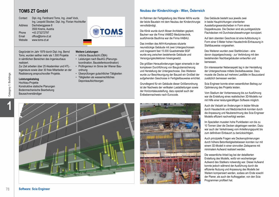
78
1
Cate
gory
1: B
uild
ings
TOMS ZT GmbHContact Dipl.-Ing. Ferdinand Toms, Ing. Josef Vock,
Ing. Leopold Stocker, Dipl. Ing. Florian HochkoflerAddress Dachsberggasse 8 3500 Krems, AustriaPhone +43 273272797Email [email protected] www.toms-zt.at
Neubau der Kinderchirugie - Wien, Österreich
Im Rahmen der Fertigstellung des Wiener AKHs wurde der letzte Baustein mit dem Neubau der Kinderchirurgie vervollständigt.
Die Klinik wurde durch Moser Architekten geplant. Bauherr war die Firma VAMED Medizintechnik, ausführende Baufirma war die Firma HABAU.
Das inmitten des AKH-Komplexes situierte neunstöckige Gebäude mit zwei Untergeschossen und insgesamt fast 15.000 Quadratmeter BGF wurde eng zwischen bestehende Gebäude und Versorgungskollektoren hineingesetzt.
Die größten Herausforderungen lagen einerseits in der komplexen Durchführung von Baugrubensicherung und Herstellung der Untergeschosse. Des Weiteren wurde zur Beschleunigung der Bauzeit ein Großteil der aufgehenden Geschosse in Fertigteilbauweise errichtet.
Grundlegend für ein Gebäude dieser Größenordnung ist der Nachweis der vertikalen Lastableitungen sowie der Horizontalaussteifung, dazu speziell auch der Erdbebennachweis nach Eurocode.
Das Gebäude besteht aus jeweils zwei in beide Hauptrichtungen orientierten Aussteifungswandscheiben in Form eines Doppelkreuzes. Die Decken sind als punktgestützte Flachdecken mit Durchstanzbewehrungen konzipiert.
Auf dem obersten Geschoss ist eine Aufstockung in Form einer 5 Meter hohen Haustechnik-Einhausung in Stahlbauweise vorgesehen.
Des Weiteren wurden zwei Stahlbrücken - eine davon doppelgeschossig - zur Verbindung mit den bestehenden Nachbargebäuden entworfen und bemessen.
Ein interessanter Nebenaspekt lag in der Herstellung der Untergeschosse mittels Deckelbauweise. Dazu musste die Decke auf mehrere Lastfälle im Bauzustand zusätzlich bemessen werden.
Scia Engineer konnte einen wesentlichen Beitrag zur Optimierung des Projekts leisten.
Vom Stadium der Vorbemessung bis zur Ausführung war die Erstellung eines realistischen 3D-Modells nur mit Hilfe einer leistungskräftigen Software möglich.
Auch die Vielzahl an Änderungen in letzter Minute durch Haustechnik und Medizintechnik konnten durch die Anpassung und Neuberechnung des Scia Engineer Modells effizient nachverfolgt werden.
Im Speziellen mussten hohe Punktlasten von bis zu 10 Tonnen über die Decken abgetragen werden. Dazu war auch der Verkehrsweg vom Anlieferungspunkt bis zum definitiven Einbauort zu berücksichtigen.
Auch prinzipielle Fragen wie Deckenoptimierungen durch höhere Betonfestigkeitsklassen konnten nur mit einem 3D-Modell in einer sinnvollen Zeitspanne mit minimalem Aufwand realisiert werden.
Die wesentliche Arbeit lag bei der detaillierten Erstellung des Modells, wofür ein wochenlanger Aufwand des Statikers notwendig war. Dieser Aufwand konnte jedoch während der Ausführung durch die effiziente Nutzung und Anpassung des Modells bei Weitem kompensiert werden, sodass am Ende sowohl der Planer, als auch der Auftraggeber, von den Scia Programmen profitiert hat.
Gegründet im Jahr 1979 durch Dipl.-Ing. Bernd Toms, wurden seither mehr als 1.500 Projekte in sämtlichen Bereichen des Ingenieurbaus realisiert.Zur Zeit arbeiten über 25 Akademiker und HTL- Ingenieure sowie über 30 freie Mitarbeiter an der Realisierung anspruchsvoller Projekte.
LeistungskatalogHochbau-ProjekteKonstruktive statische Planungen Bodenmechanische BearbeitungBausachverständiger
Weitere Leistungen• örtliche Bauaufsicht (ÖBA)• Leistungen nach BauKG (Planungs-
koordination, Baustellenkoordination)• Prüfingenieur im Sinne der Wiener Bau-
ordnung• Überprüfungen gutachtlicher Tätigkeiten• Tätigkeiten als wasserrechtliches
Deponieaufsichtsorgan
Software: Scia Engineer
TOMS ZT GmbH . . . . . . . . . . . . . . . . . . . . . . . . . . . . . . . . . . . . . Chirurgical Centre for Children - Vienna, Austria

79
Project information
Short project description
Nemetschek Engineering User Contest 2011 - Category 1: Buildings
Cate
gory
1: B
uild
ings
1
Owner Allgemeines Krankenhaus WienArchitect Moser ArchitektenGeneral Contractor HABAUEngineering Office TOMS ZT GmbHConstruction Period From December 2009 to September 2011Location Vienna, Austria
The project is about the final building stage of the Vienna General Hospital, namely the construction of the new Chirurgical Centre for Children. The building is a nine-storeyed concrete tower with 2 floors below the main level and a surface of about 15.000 m2. The slabs are supported by columns without beams. The façade components have been realized of precast concrete elements. Part of the project was a construction of a steel enclosure on the upper floor and two connection bridges made of steel. The main challenges were the difficult ground conditions and an extremely short construction period.
Chirurgical Centre for ChildrenVienna, Austria
TOMS ZT GmbH . . . . . . . . . . . . . . . . . . . . . . . . . . . . . . . . . . . . . Chirurgical Centre for Children - Vienna, Austria

80
1
Cate
gory
1: B
uild
ings
Landesklinikum Weinviertel - Mistelbach, Österreich
Das Projekt des Neu- und Umbaus des Landeskrankenhauses Mistelbach gilt als das zurzeit größte Krankenhausprojekt Niederösterreichs.Das Konsortium Vamed-Alpine realisiert im Rahmen eines Betreibermodells dieses Projekt. Die ARGE Maurer-Moser Architekten ist mit der Planung beauftragt.
Kernstück des Projekts ist der Neubau eines achtgeschossigen Gebäudes mit insgesamt ca. 27.000 m2 Bruttogeschossfläche. Der Neubau wird in die bestehende Hanglage hineingebaut, sodass sich Baugrubentiefen von bis zu 15 Metern ergeben.
Das Tragwerk besteht aus einer reinen Stahlbetonkonstruktion. Unterzugsfreie Flachdecken sowie offene, punktstützte Außenfassaden ermöglichen eine optisch ansprechende Architektur sowie eine optimale Führung der Haustechnikversorgung.
Auf dem obersten Geschoß ist der Hubschrauberlandeplatz angeordnet. Für die dadurch entstehenden Hubschrauber- Verkehrslasten wurde das Tragwerk mittels Scia Engineer entsprechend optimiert.
Der Erdbebennachweis wurde mit den Dynamik-Modulen von Scia Engineer nach dem Antwortspektrenverfahren des Eurocode 1998 geführt. Eine vom Aufwand her sinnvolle Berechnung ist bei diesem Verfahren ausschließlich mit der Methode der finiten Elemente möglich.
Einen projektspezifischen Sonderfall stellt das Fundierungskonzept dar. Die gemischte Fundierung besteht einerseits aus flachgegründeten Tiefgeschossen, andererseits aus einer Teilfundierung mittels Großbohrpfählen.
Zur Berechnung der Tiefgründung wurden mittels Scia Engineer eine Vielzahl an Varianten untersucht. Da die Tragfähigkeit des Bodens je nach Tiefe und Lage stark variierte, mussten die entsprechenden Bodenkennwerte jeweils in den ungünstigsten Fällen kombiniert werden. Dies konnte nur mit einer leistungsfähigen Software, wie es Scia Engineer ist, in einem sinnvollen Zeitrahmen realisiert werden. Das gilt auch für die oft kurz vor der Deadline herangetragenen Änderungswünsche, welche mit der Software in kürzester Zeit nachgerechnet werden konnten.
Bei der Außenfassade wurden gleichfalls mehrere Varianten durchkalkuliert. Einerseits wurde eine klassische Ortbetonfassade (Lochfassade), andererseits eine nichtragende Variante mittels vorgehängter Fertigteile erarbeitet. Die kostengünstigere Variante wurde gewählt.
Prinzipiell kann gesagt werden, dass die Vielzahl an Varianten zur Kostenoptimierung nur mit einem effizienten 3D Statikprogramm wie Scia Engineer sinnvoll bearbeitet werden können. Der Mehrwert dieser Software lässt sich somit nicht nur direkt an der Effizienzsteigerung im Ingenieurbüro, sondern auch potentiell an den gesamten Herstellungskosten nachweisen.
TOMS ZT GmbH . . . . . . . . . . . . . . . . . . . . . . . . . . . . . . . . . . . . . Federal State Hospital Weinviertel - Mistelbach, Austria
Software: Scia Engineer
Gegründet im Jahr 1979 durch Dipl.-Ing. Bernd Toms, wurden seither mehr als 1.500 Projekte in sämtlichen Bereichen des Ingenieurbaus realisiert.Zur Zeit arbeiten über 25 Akademiker und HTL- Ingenieure sowie über 30 freie Mitarbeiter an der Realisierung anspruchsvoller Projekte.
LeistungskatalogHochbau-ProjekteKonstruktive statische Planungen Bodenmechanische BearbeitungBausachverständiger
Weitere Leistungen• örtliche Bauaufsicht (ÖBA)• Leistungen nach BauKG (Planungs-
koordination, Baustellenkoordination)• Prüfingenieur im Sinne der Wiener Bau-
ordnung• Überprüfungen gutachtlicher Tätigkeiten• Tätigkeiten als wasserrechtliches
Deponieaufsichtsorgan
TOMS ZT GmbHContact Dipl.-Ing. Ferdinand Toms, Ing. Josef Vock,
Ing. Leopold Stocker, Dipl. Ing. Florian HochkoflerAddress Dachsberggasse 8 3500 Krems, AustriaPhone +43 273272797Email [email protected] www.toms-zt.at

81
Project information
Short project description
Nemetschek Engineering User Contest 2011 - Category 1: Buildings
Cate
gory
1: B
uild
ings
1
The project is about the new construction and modification of the federal state hospital in Mistelbach, Austria. The core pieces of the building are the 8 floors with a total area of about 27.000 m², the 15 m deep building pit and the landing platform for the rescue helicopter. The structural analysis of earthquakes (Eurocode 1998) and the conception of the foundation were done with Scia Engineer. For the outer facade it was calculated if it was better to use an in-situ concrete facade or a non-load bearing alternative. Scia Engineer did not only increase efficiency in the office but also showed the way to the most economical construction on site.
Federal State Hospital WeinviertelMistelbach, Austria
TOMS ZT GmbH . . . . . . . . . . . . . . . . . . . . . . . . . . . . . . . . . . . . . Federal State Hospital Weinviertel - Mistelbach, Austria
Owner Land NiederösterreichArchitect Moser ArchitektenGeneral Contractor AlpineEngineering Office ZT TOMSConstruction Period From April 2010 to January 2013Location Mistelbach, Austria

82
1
Cate
gory
1: B
uild
ings
Allgemein Öffentliches Krankenhaus - Zell am See, Österreich
Das Krankenhaus Zell am See gilt als das wichtigste Schwerpunktkrankenhaus im Salzburger Pinzgau. Aufgrund von Kapazitätsengpässen wird das Krankenhaus durch einen großzügigen Umbau und Neubau erweitert.
Geplant wurde die Klinik vom Büro Domenig-Wallner aus Graz, welches als Sieger aus einem Wettbewerb hervorging.
Das Bauwerk integriert sich in den Bestand, und passt sich an die örtlichen Gegebenheiten der unmittelbaren Lage zum Zeller See bewusst an.
Der Neubau des Krankenhauses Zell besteht aus zwei länglichen Bauwerken mit je 4 Geschossen. Der dem Altbau anschließende ca. 120 m lange Baukörper besteht aus den Bauteilen West und Ost. Parallel dazu auf der dem See zugewandten Seite wird der Bauteil Süd hergestellt.
Das Tragwerk ist als Stahlbetonkonstruktion entworfen. Um eine möglichst leichte Führung der Haustechnikversorgung gewährleisten zu können,
wurden soweit wie möglich unterzugsfreie Flachdecken konzipiert.
Auf den obersten Geschossen der neu errichteten Bauteile ist jeweils eine Aufstockung in Form einer 3 Meter hohen Haustechnik-Einhausung in Stahlbauweise vorgesehen.
Zwischen den Bauteilen sind auf allen Geschossen Verbindungsbrücken sowohl zwischen den Neubauten untereinander, als auch als Verbindung zum Bestand angeordnet.
Als Gründungskonzept wurde eine Fundierung mittels duktiler Rammpfähle vorgesehen. Da das tragfähige Substratum von Ost nach West in Richtung See abfällt, werden die Pfähle zum Teil schwebend in der sandig kiesigem Bodenschicht bzw. am Fels aufsitzend eingebaut, wobei dem Systemwechsel durch konstruktive Maßnahmen (Setzungsfugen) Rechnung getragen werden.
Hier war die Berechnung mittels Scia Engineer 3D Modellen insofern sehr hilfreich, da dadurch verschiedene Federsteifigkeiten der Duktilpfähle sowie der Fundamentplatten simuliert werden konnten. Durch diese Berechnung konnten in kürzester Zeit ein realitätsgetreues und kostenoptimiertes Fundierungskonzept erstellt werden.
Die Tiefgeschosse und Kollektorgeschosse wurden in wasserundurchlässiger Bauweise nach der Richtlinie „Weisse Wannen“ hergestellt, da durch die seenahe Lage der Grundwasserspiegel quasi der Geländeoberkante entspricht.
Da im Rahmen von mehrfachen Kostenoptimierungsphasen auch zahlreiche Tragwerksvarianten durchgerechnet werden mussten, konnte bei diesem Projekt Scia Engineer einen wesentlichen Beitrag dazu leisten, den Zeitaufwand durch Umplanungen zu reduzieren und den Kostenaufwand zu minimieren.
TOMS ZT GmbH . . . . . . . . . . . . . . . . . . . . . . . . . . . . . . . . . . . . General Public Hospital - Zell am See, Österreich
Software: Scia Engineer
Gegründet im Jahr 1979 durch Dipl.-Ing. Bernd Toms, wurden seither mehr als 1.500 Projekte in sämtlichen Bereichen des Ingenieurbaus realisiert.Zur Zeit arbeiten über 25 Akademiker und HTL- Ingenieure sowie über 30 freie Mitarbeiter an der Realisierung anspruchsvoller Projekte.
LeistungskatalogHochbau-ProjekteKonstruktive statische Planungen Bodenmechanische BearbeitungBausachverständiger
Weitere Leistungen• örtliche Bauaufsicht (ÖBA)• Leistungen nach BauKG (Planungs-
koordination, Baustellenkoordination)• Prüfingenieur im Sinne der Wiener Bau-
ordnung• Überprüfungen gutachtlicher Tätigkeiten• Tätigkeiten als wasserrechtliches
Deponieaufsichtsorgan
TOMS ZT GmbHContact Dipl.-Ing. Ferdinand Toms, Ing. Josef Vock,
Ing. Leopold Stocker, Dipl. Ing. Florian HochkoflerAddress Dachsberggasse 8 3500 Krems, AustriaPhone +43 273272797Email [email protected] www.toms-zt.at
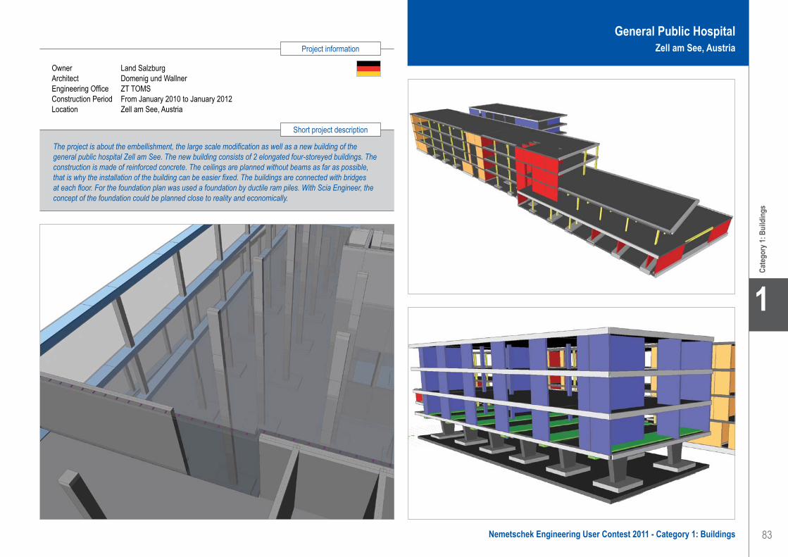
83
Project information
Short project description
Nemetschek Engineering User Contest 2011 - Category 1: Buildings
Cate
gory
1: B
uild
ings
1
Owner Land SalzburgArchitect Domenig und WallnerEngineering Office ZT TOMSConstruction Period From January 2010 to January 2012Location Zell am See, Austria
The project is about the embellishment, the large scale modification as well as a new building of the general public hospital Zell am See. The new building consists of 2 elongated four-storeyed buildings. The construction is made of reinforced concrete. The ceilings are planned without beams as far as possible, that is why the installation of the building can be easier fixed. The buildings are connected with bridges at each floor. For the foundation plan was used a foundation by ductile ram piles. With Scia Engineer, the concept of the foundation could be planned close to reality and economically.
General Public HospitalZell am See, Austria
TOMS ZT GmbH . . . . . . . . . . . . . . . . . . . . . . . . . . . . . . . . . . . . General Public Hospital - Zell am See, Österreich

84
1
Cate
gory
1: B
uild
ings
Vahanen OyContact Mika Konttila, Marja-Riitta Lång, Ulla Harju,
Tero AaltonenAddress Halsuantie 4 00420 Helsinki, FinlandPhone +358 207698698Email [email protected] www.vahanen.com
Kamppi Chapel of Silence - Helsinki, Finland
The Kamppi chapel of silence is located on the south side of the busy Narinkka square in central Helsinki. With its curved wood façade, the small sacral building flows into the cityscape. Simultaneously the chapel’s gently shaped interior space embraces visitors and shields them from the bustling surrounding city life.
The actual chapel is located in a wooden volume. Secondary structures are located in a hall opening up towards the square. The entrance doubles as exhibition space.
The sacral space is a calm environment; the chapel’s inner walls are made of thick oiled alder planks. The furniture is also made of solid wood.
The façades will be made out of sawn-to-order horizontal finger jointed pine wood planks, which will be treated with a micro-pro pressure treatment and surface finishing. The constructive frame consists of solid glulam elements.
ArchitectThe (award-winning) development was realised by K2S Architects in central Helsinki.
General description of the project• Chapel, wooden frame: 104 m2
• Staffroom, concrete frame: 18 m2
• Public info and exhibition space, concrete frame: 80 m2
• Other spaces, concrete frame: 64 m2
• Apartment area: 266 m2
• Gross area: 320 m2
The acoustic demands placed upon the building are the most important factors that affect the structural design.
The design of the exterior wooden façade will be a challenge, because it has to be bent smoothly around the structural shell.The surrounding buildings and car park ramp from the Forum shopping centre should be in normal use during the construction period, which means care should be taken during the designing and constructing stages to consider the site logistics, working schedule, work phasing and protective covering.
The source data included 2D vector files and Rhinoceros 3D surface models.The only 3D source data came from the Rhinoceros file.Using these files as a starting point, all the construction and reinforcement modelling was made using Allplan Engineering.All different kinds of drawings like plans, sections, reinforcements with steel schedule, demolition plans and details are made from this single Allplan project. End data can be produced as IFC, dwg, pdf and plt files which are sent to an internet based, common file bank for the project, where an authorized user can access them.
Solid Glulam columns are modelled with Allplan 3D modelling which is based on the architect’s Rhinoceros 3D surface model.The most challenging problem was to model the chapel’s columns because both of the surface profiles are different.Every column is individual and will be cut using a CNC machine, these CNC files will be exported from Allplan.The exterior wooden surface of the chapel is made like a wooden boat, handmade by a carpenter.Also the chapel’s foundation follows the shape of the walls, which made the task of reinforcement designing quite demanding.Reinforcement schedules are very helpful for the contractor, especially in this kind of multi-shaped project.
The shape and form of the chapel are rather complex and the acoustic demands very strict.The wooden and concrete structures have been designed with the help of Allplan Engineering.It is hard to believe that someone could make construction drawings for this kind of building without a proper BIM program like Allplan.The property of Allplan Engineering for reinforcing multi-formed structures is used in order to do the work fast, accurately and effectively.
Allplan Engineering is a powerful designing program in this kind of complex free-shape constructions. Its ability to import and export different kinds of 2D, 3D and IFC formats makes it easier to co-operate efficiently with other designers.
Vahanen Group is one of the biggest Finnish owned technical consulting organizations in the construction and property branch.
We offer a wide scope of services in architecture, geotechnics, building services and structural engineering, in refurbishment and property management, expert services in building physics together with environmental consulting.
Our main focus is on developing sustainable constructions throughout our services. There are more than 400 professionals working in the Vahanen Group.
Our network extends from Finland to Russia, the Baltic States, Romania and the Gulf Area.
Our mission is to develop a safe, healthy, ecologically balanced built environment for generations to enjoy.
Software: Allplan Engineering
Vahanen Oy. . . . . . . . . . . . . . . . . . . . . . . . . . . . . . . . . . . . . . . . . Kamppi Chapel of Silence - Helsinki, Finland

85
Project information
Short project description
Nemetschek Engineering User Contest 2011 - Category 1: Buildings
Cate
gory
1: B
uild
ings
1
Owner The Parish Union of HelsinkiArchitect Arkkitehtitoimisto K2S OyGeneral Contractor Pakrak OyEngineering Office Vahanen OyConstruction Period From March 2011 to March 2012Location Helsinki, Finland
This project is about the Kamppi chapel of silence, located on the busy Narinkka square in central Helsinki. It offers a place to quiet down and compose oneself in one of Finland’s most lively urban spaces.All the construction and reinforcement modelling was made using Allplan Engineering and BIM throughout the project. The ability to import and export different kinds of 2D, 3D and IFC formats makes it easy to co-operate efficiently with other designers.
Kamppi Chapel of SilenceHelsinki, Finland
Vahanen Oy. . . . . . . . . . . . . . . . . . . . . . . . . . . . . . . . . . . . . . . . . Kamppi Chapel of Silence - Helsinki, Finland

86
1
Cate
gory
1: B
uild
ings
Software: Nexis, Scia Engineer
Aupark Shopping Centre - Žilina, Slovak Republic
The Aupark Shopping Centre of Žilina is a multifunctional building with shops, cafés, banks, services and parking in the basement. The whole structure has the length of 216.70 m. It consists of three dilatation units. The block has three underground and four aboveground floors. The height of the building was limited to the height of the surrounding buildings and this could be obtained only by using beamless floors with chaplets and reinforced column stripes. In other dilatation units with a larger design height the beamed ceilings were used. The construction of the building took more time, mainly due to a combination of monolithic vertical structures and precast joist ceilings, which were manufactured and assembled by another supplier.
Description of the concrete structuresThe described dilatation block with footprint parameters 63.32 m x 64.90 m is designed as a monolithic reinforced concrete construction. Only the stairs are prefabricated.
The main vertical elements are columns with a modular scheme 15.0 x 7.50 m in the basement and 15.0 x 10.0 m in the upper floors . The maximum cross-section of columns, 700 x 700 mm, transmits a vertical reaction of about 15 MN. The columns gradually change their cross section to 600 x 600 mm in the top floors. The perimeter walls in the basement, with a thickness of 300 mm, spread the reactions from the top of the building and also take the pressure of the surrounding soil to a depth of about 10 m. The building is reinforced in the corners through communication and technological cores with walls with a thickness of 200 mm.
In all floors, ceilings are designed as monolithic reinforced concrete beamless chaplet slabs of concrete C 30/37. This type of ceiling with low height is also suitable for the problematic installation and handling of heavy beam elements. The basic thickness of the slab is 220 mm, the reinforced column stripes are 2.40 m wide and 450 and 600 mm thick. At the places of the columns chaplets are used with a thickness of 850 mm. In the upper floors with larger load and with weakening of the plate with large holes - square with a large skylight 30 x 30 m, plastic lightened hollow bodies of Cobiax were used. Deflections of the ceilings were
monitored during the construction and they meet the assumptions of the static calculation.
Foundation and loading dataThe foundation in the open dry pit shoring was designed to base pads and strips on the 10 m thick layer of consolidated gravel. During the construction, the increasing load sequentially introduced deformations in the soil. The lower basement slab with a thickness of 250 mm was realized only after the structure had been cast. The design consists of the calculation and evaluation of a number of load cases and their complex combination effect. Besides the self-weight, the following loads were considered: load layers of a floor with the value of 2.50 kNm-2, effective loads for garages on the underground ceilings of 2.50 kNm-2 and for commercial areas a standardized value of 5.0 kNm-2 and on the roof a technology value of 4.50 kNm-2. The climatic loads for snow loading in area III were s0 = 1.0 kNm-2 and for wind loading w0 = 0.45 kNm-2. In addition, the seismicity load of 8° MSK-64 was considered.
Description of the static calculationThe static calculation was prepared as a 3D model with the software Nexis (ESA-Prima Win). The most dangerous combinations were calculated according to STN 730035 in two basic combinations - load-bearing capacity and deformations. The model contains 1.154 macros in 1D and 13.900 macros in 2D. The foundation pads and strips were modelled on elastic foundation with consideration of the real values of the upper construction load on the 3D model.
Deformations of the ceilingsCeilings for commercial areas, with a span of 15.0 m in place of column strips with a thickness of 600 mm, bending moment 350 kNm and reinforcement Ø20 to 150 mm, had a deflection of 60 mm. After lightening of the column strips with plastic hollow bodies Cobiax Ø450 mm, the bending moment was decreased to 230 kNm and the reinforcement to Ø16 to 150 mm with a maximum deflection of 25 mm. The problem of the deflection of the 5 m cantilever was solved in the same way.
The company VHS-SK-PROJEKT, s.r.o. was established in 2001 as a part of Váhostav. The Váhostav company was founded in 1954 as a company for construction of water works - power stations and dams - and industrial plants.
The company VHS-SK-PROJEKT, s.r.o. offers: • Complex architectonic and civil engineering
services.• Buildings and civil engineering activities:
design and engineering, structural static and dynamic analysis of reinforced concrete, steel and timber structures. Structural static and
dynamic analysis and foundation engineering are prepared using Nexis (ESA-Prima Win), Scia Engineer, Fine.
• Foundation engineering and design.• Design for reinforced concrete, prefabricates,
steelwork and timber structures.
The team consists of experienced senior engineers as well as junior engineers with new ideas. This cooperation is successful. The young staff members feel safe under the wings of their experienced colleagues and at the same time they enrich the experienced with new inventiveness.
VHS-SK-PROJEKT, s.r.o.Contact Milan KadlečíkAddress Kysucká cesta 3 01001 Žilina, Slovak RepublicPhone +421 41 7003090Email [email protected] www.vhs-sk-projekt.sk
VHS-SK-PROJEKT, s.r.o. . . . . . . . . . . . . . . . . . . . . . . . . . . . . . . Aupark Shopping Centre - Žilina, Slovak Republic

87
Project information
Short project description
Nemetschek Engineering User Contest 2011 - Category 1: Buildings
Cate
gory
1: B
uild
ings
1
The shopping and entertainment centre ‘Aupark’ is located between the pedestrian zone and inner ring road of the city. The extensive interior space of the centre with natural daylight created a new covered square and a new street that is the continuation of the pedestrian zone in Žilina. The whole building is divided into three dilatation units, the load-bearing system is a reinforced concrete monolith; vertical elements are formed by pillars as well as reinforced wall communication cores. The ceilings of the aboveground floors, with a span of 15 m, are lightened with hollow bodies of the Cobiax system.
Owner HB Reavis Slovak RepublicArchitect Ing. Arch. Juraj Jančina, Ing. Arch. Igor MazúchGeneral Contractor Skybau, s.r.o. ŽilinaEngineering Office AK JančinaConstruction Period From 2007 to October 2010Location Žilina, Slovak Republic
Aupark Shopping CentreŽilina, Slovak Republic
VHS-SK-PROJEKT, s.r.o. . . . . . . . . . . . . . . . . . . . . . . . . . . . . . . Aupark Shopping Centre - Žilina, Slovak Republic

88
1
Cate
gory
1: B
uild
ings
Z Group_Birou de Structuri SRL . . . . . . . . . . . . . . . . . . . . . . . . . Anchor Plaza Downtown - Bucharest, Romania
Z Group_Birou de Structuri SRLContact Diana Zagaican, Lucian BogorodeaAddress Str.LamotestI No.3-5 041026 Bucharest, RomaniaPhone +40 723694705Email [email protected]
Anchor Plaza Downtown - Bucharest, Romania
Structural concept and particularitiesThis project represents an office building having 2 basements, a ground floor, 24 floors and 1 technical floor. The gross built area is 75.290 m2, the total height above the ground is 99.14 m, there are 2 underground basements. The two basements have different heights: 4.28 m (B1) and 4.00 m (B2).The typical storey height is 3.74 m
Hydrological conditionsThe site is located at the address 55th-59th Calea Vitan, Bucharest and it has an underground aquifer with the upper level at -8.3 m.
FoundationThe underground levels were designed as a rigid box, with a raft foundation of 200 cm in thickness, basement slabs of 35 cm in thickness and interior shear walls (20, 40, 60,100 cm). From the raft foundation two types of columns start: the reinforced concrete square columns 100 x 100 cm which stop in the slab over the basement and composite columns with a square section of 120 x 120 cm which continue in the superstructure.Because of the poor foundation soil, the raft foundation will be laid on 120 cm diameter piles that go as deep as -30.40 m.
On the perimeter of the basements there will be an enclosure made of 90 cm diameter secant piles which are going to -30.40 m below the ground surface. These reinforced concrete waterproof piles will be connected on their top with a strong crown beam (130 x 150 cm). In front of the piles there is a perimeter shear wall with the thickness of 40 cm.
The concrete used in foundations is class C30/37 waterproof. The concrete in the reinforced piles is class C25/30. The steel reinforcement used in foundations is PC52 (S355), OB37 (S235).
StructureThe structure is made as a composite system: steel and reinforced concrete. All columns are rectangular, made of steel tubes 800 x 800 x 50 mm and 900 x 900 x 50 mm (in two corners) and a few columns that are connecting the shear walls
have the Malta Cross section of two profiles HEB700. Interior and perimeter beams are made of steel profiles HEM 700 x 352+. The coupling beams of central core have sections 100 x 140 cm and they are made of reinforced concrete with a profile HEB700 inside.
On the perimeter of the building there are steel bracings made of tubes a having section of 300 x 500 x 10 mm, placed in X shape, one bracing in every six floors.The circular core shear walls which contain the stairs and elevators are all 100 cm thick, made of reinforced concrete with rigid reinforcement inside.The vertical circulation of the building will be done by 8 high speed elevators (3.5 m/s). All the elevators will have 25 stops.
All the slabs are 20 cm thick, except for the terrace floor that has a thickness of 30 cm, which is needed for the heavy equipment that will be placed on the top of the building.The column axial distance for the office area has been designed as 8.35 m. This size is creating very suitable working conditions for the open office arrangement and has very big advantages in the basement floors where it allows for a clever parking system.
The concrete used in the super-structure is high class concrete C50/60 in the first 6 floors and C35/45 in the remaining storeys.
The steel in the rigid reinforcement is S355 J2+N, and in the flexible reinforcement it is S355 and S235.
Z Group_Birou de Structuri SRL is a young company specialized in computer aided design of complex structures in the structural engineering and industrial fields. The main activity of the company is designing, consulting and construction expertise.Founded in 2001 in Bucharest, Z Group_Birou de Structuri SRL has become a well-known company on the market through its professionalism and seriousness.We design: High-rise office and residential buildings (16 stories and more) with large span;Commercial Centres (Malls); Auto showrooms;
Car parks; Houses; Warehouses; Production and industrial halls.
Our team consists of 15 experienced engineers who design (draft) and compute structures subject to seismic forces, who are committed to provide innovative, effective and sustainable design solutions for the most complicated structures, who have the skills to manage complex projects and are dedicated to the success of any project for they have the ability to react promptly and positively to emergency requirements.
Software: Allplan Engineering

89
Project information
Short project description
Nemetschek Engineering User Contest 2011 - Category 1: Buildings
Cate
gory
1: B
uild
ings
1
Anchor Plaza Downtown Bucharest, Romania
Z Group_Birou de Structuri SRL . . . . . . . . . . . . . . . . . . . . . . . . . Anchor Plaza Downtown - Bucharest, Romania
Owner Anchor Grup, BucharestArchitect B-Design, TurkeyGeneral Contractor Anchor Grup Engineering Office Z Group_Birou de Structuri SRL, BucharestLocation Bucharest, Romania
This project represents the Anchor Plaza office building having 2 basements, a ground floor, 24 floors and 1 technical floor. The underground levels were designed as a rigid box, with a raft foundation of 200 cm in thickness, basement slabs of 35 cm in thickness and interior shear walls (20, 40, 60, 100 cm). The raft foundation rests on 120 cm diameter piles (-30.40 m deep). The structure is made as a composite system: steel and reinforced concrete.

At Nemetschek Scia, we are committed to constantly bring our innovative technology and expertise to the highest level and therefore inspire our customers and partners to move their limits.
www.scia-online.com
Nemetschek Scia nv - Industrieweg 1007 - B-3540 Herk-de-Stad - Tel. +32 13 55 17 75 - [email protected]
enabling innovation in construction

91
Any type of structure that fits within civil engineering, including any type of bridge (beam, arch, cable-stayed, suspension…), tunnels, bulkheads, locks, barrages, in short general infrastructure...
for which Nemetschek Engineering Group software has been used.
Category 2: Civil Structures
2Nemetschek Engineering User Contest 2011 - Category 2: Civil Structures
Cate
gory
2: C
ivil S
truct
ures
2

92
2
amsler bombeli et associés saContact David AmslerAddress Avenue de Cour 135 1007 Lausanne, SwitzerlandPhone +41 2 16142000Email [email protected] www.amsler-bombeli.ch
Pont Hans-Wilsdorf - Genève, Suisse
« entre ouvrage d’art et œuvre d’art » Le projet est financé par la Fondation Hans Wilsdorf et sera cédé à la Ville de Genève en fin de travaux.La conception architecturale originale est l’œuvre de l’atelier d’architecture Brodbeck-Roulet à Genève, en étroite collaboration avec le bureau d’ingénieurs civils amsler bombeli et associés sa. Il s’agit d’une structure en forme de tube d’une portée unique de 85.40 mètres à l’intérieur duquel passe le tablier de 15.50 mètres de largeur recevant les voies de circulation pour tout type de véhicules, ainsi que deux pistes cyclables et deux larges trottoirs. L’ouvrage est posé sur deux culées en béton armé. Sur chaque culée, deux appuis pots latéraux reprennent les charges verticales et un appui central reprend les charges horizontales transversales générées par une obstruction éventuelle du cours d’eau en cas de crue exceptionnelle.
Conception architecturaleLa structure spatiale elliptique est composée de différents types d’éléments : les trois caissons inférieurs, les deux portiques d’entrée, les deux longerons supérieurs, les deux arcs principaux, les diagonales elliptiques, ainsi que les trois courbes enveloppe.
Le calcul statique de l’ouvrage avec Scia Engineer a défini précisément la qualité d’acier et les épaisseurs de tôles nécessaires à la fabrication des éléments structurels qui possèdent leur propre géométrie spatiale.La structure métallique est composée de caissons de 40 x 40 cm qui épousent la forme elliptique générale de l’ouvrage. Entre les deux portiques d’entrée, deux types de « diagonales elliptiques » sont répartis symétriquement le long de l’ouvrage. Plus de 250 sections paramétriques ont été saisies dans le programme, garantissant ainsi le strict respect de leur géométrie.
Calculs avec Scia EngineerLe premier modèle fut entièrement réalisé en barres avec des sections tubulaires d’épaisseur constante d’aire et d’inertie équivalente à une section de 400 x 400 mm. Les résultats de ce calcul nous ont conduits à ajouter deux arcs composés d’un RND 300 afin
de limiter les déformations excessives. Un calcul dynamique de la structure a permis d’analyser la réaction de la structure face au séisme et définir la fréquence propre de l’ouvrage.
Le deuxième modèle est réalisé en éléments barres pour les diagonales elliptiques composées de sections paramétriques tandis que la base des portiques d’entrée est constituée d’éléments coques. Les déformations admissibles ainsi que les contraintes dans les sections réelles ont été vérifiées par un calcul non-linéaire géométrique. Il s’est avéré nécessaire de rajouter quatre anneaux elliptiques supplémentaires, deux au centre et deux aux extrémités. Par la suite nous avons complété la base des portiques d’entrées par l’ajout de raidisseurs pour vérifier l’introduction des réactions d’appuis.
Platelage de montageLe pont est assemblé sur un platelage de montage qui est appuyé sur les deux culées, ainsi que sur les cinq appuis provisoires dans l’Arve. Sur ces appuis, un réseau de solives supporte une tôle nervurée ainsi qu’un revêtement en aluminium. Ce platelage provisoire sera démonté à la fin de la construction du pont en coupant les profilés au niveau du fond du lit de la rivière.
Tablier en béton précontraintLe tablier en béton armé d’une épaisseur moyenne de 40 cm est précontraint longitudinalement et transversalement, conférant ainsi une excellente durabilité. Le tablier est lié rigidement à la structure métallique par des goujons répartis dans des niches scellées progressivement en fonction de la mise en charge de l’ouvrage.
ConclusionsLa conception architecturale originale du pont Hans-Wilsdorf a nécessité l’élaboration d’un modèle de calcul très complexe avec Scia Engineer. Cette modélisation a permis d’adapter la structure et, grâce à une optimisation de la position des diagonales, à l’introduction d’arcs, à la variation des épaisseurs et des qualités d’acier, le pont répond à toutes les exigences d’un ouvrage d’art moderne.
La société amsler bombeli et associés, active depuis 31 ans, est spécialisée dans la géotechnique, les travaux spéciaux, les structures porteuses, les ouvrages d’art, les routes et canalisations, ainsi que dans l’environnement, par l’application systématique des concepts du développement durable.Parmi les projets réalisés, on peut compter des grands centres administratifs et publics, des immeubles, des salles de spectacles, d’importants aménagements urbains comme des nouvelles lignes de tram, des réseaux ferroviaires ou des ponts.
Les études et la réalisation du pont Hans-Wilsdorf ont nécessité la constitution d’une équipe pluridisciplinaire regroupant des spécialistes en travaux spéciaux, en génie civil, en environnement et en structures porteuses d’ouvrages d’art, tous intégrés au sein d’une seule et même société. Les calculs statiques de l’ouvrage ont été réalisés par M. Patrick Cherzai.
Software: Scia Engineer
amsler bombeli et associés sa . . . . . . . . . . . . . . . . . . . . . . . . . . Hans Wilsdorf Bridge - Geneva, Switzerland
Win
ner -
Civi
l Stru
ctur
esWinner

93
Project information
Short project description
Nemetschek Engineering User Contest 2011 - Category 2: Civil Structures
2
Win
ner -
Civi
l Stru
ctur
es
Owner Fondation Hans-WilsdorfArchitect Atelier d’architecture Brodbeck-Roulet saEngineering Office amsler bombeli et associés saConstruction Period From November 2009 to February 2012Location Geneva, Switzerland
The original architectural design is the work of the architect’s firm Brodbeck-Roulet in Geneva. They worked in close collaboration with the civil engineering office ‘amsler bombeli et associés SA’. Given the complexity of the geometry of the bridge, the calculation of the structure required the development of several models with very sophisticated calculations, which were performed with Scia Engineer. On this basis, an optimization of thicknesses and steel grades has been done through the input of parametric cross-sections as well as the extensive use of shell elements for the detailing study of several parts of the structure.
Hans Wilsdorf BridgeGeneva, Switzerland
amsler bombeli et associés sa . . . . . . . . . . . . . . . . . . . . . . . . . . Hans Wilsdorf Bridge - Geneva, Switzerland
Quote of the Jury
“This state-of-the-art project with steel and prestressed concrete convinced the jury. The project shows the splendid result of a merger between an architectural design, which aims to be an organic structure, and engineering skills supported by flexible software that is able to deal with complex sustainable structures.”
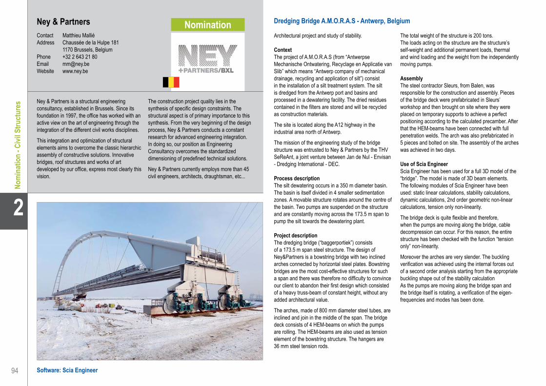
94
2
Software: Scia Engineer
Ney & PartnersContact Matthieu MalliéAddress Chaussée de la Hulpe 181 1170 Brussels, BelgiumPhone +32 2 643 21 80Email [email protected] www.ney.be
Ney & Partners . . . . . . . . . . . . . . . . . . . . . . . . . . . . . . . . . . . . . . Dredging Bridge A.M.O.R.A.S - Antwerp, Belgium
Dredging Bridge A.M.O.R.A.S - Antwerp, Belgium
Architectural project and study of stability.
ContextThe project of A.M.O.R.A.S (from “Antwerpse Mechanische Ontwatering, Recyclage en Applicatie van Slib” which means “Antwerp company of mechanical drainage, recycling and application of silt”) consist in the installation of a silt treatment system. The silt is dredged from the Antwerp port and basins and processed in a dewatering facility. The dried residues contained in the filters are stored and will be recycled as construction materials.
The site is located along the A12 highway in the industrial area north of Antwerp.
The mission of the engineering study of the bridge structure was entrusted to Ney & Partners by the THV SeReAnt, a joint venture between Jan de Nul - Envisan - Dredging International - DEC.
Process descriptionThe silt dewatering occurs in a 350 m diameter basin. The basin is itself divided in 4 smaller sedimentation zones. A movable structure rotates around the centre of the basin. Two pumps are suspended on the structure and are constantly moving across the 173.5 m span to pump the silt towards the dewatering plant.
Project descriptionThe dredging bridge (“baggerportiek”) consists of a 173.5 m span steel structure. The design of Ney&Partners is a bowstring bridge with two inclined arches connected by horizontal steel plates. Bowstring bridges are the most cost-effective structures for such a span and there was therefore no difficulty to convince our client to abandon their first design which consisted of a heavy truss-beam of constant height, without any added architectural value.
The arches, made of 800 mm diameter steel tubes, are inclined and join in the middle of the span. The bridge deck consists of 4 HEM-beams on which the pumps are rolling. The HEM-beams are also used as tension element of the bowstring structure. The hangers are 36 mm steel tension rods.
The total weight of the structure is 200 tons.The loads acting on the structure are the structure’s self-weight and additional permanent loads, thermal and wind loading and the weight from the independently moving pumps.
AssemblyThe steel contractor Sleurs, from Balen, was responsible for the construction and assembly. Pieces of the bridge deck were prefabricated in Sleurs’ workshop and then brought on site where they were placed on temporary supports to achieve a perfect positioning according to the calculated precamber. After that the HEM-beams have been connected with full penetration welds. The arch was also prefabricated in 5 pieces and bolted on site. The assembly of the arches was achieved in two days.
Use of Scia EngineerScia Engineer has been used for a full 3D model of the “bridge”. The model is made of 3D beam elements. The following modules of Scia Engineer have been used: static linear calculations, stability calculations, dynamic calculations, 2nd order geometric non-linear calculations, tension only non-linearity.
The bridge deck is quite flexible and therefore, when the pumps are moving along the bridge, cable decompression can occur. For this reason, the entire structure has been checked with the function “tension only” non-linearity.
Moreover the arches are very slender. The buckling verification was achieved using the internal forces out of a second order analysis starting from the appropriate buckling shape out of the stability calculationAs the pumps are moving along the bridge span and the bridge itself is rotating, a verification of the eigen-frequencies and modes has been done.
Ney & Partners is a structural engineering consultancy, established in Brussels. Since its foundation in 1997, the office has worked with an active view on the art of engineering through the integration of the different civil works disciplines.
This integration and optimization of structural elements aims to overcome the classic hierarchic assembly of constructive solutions. Innovative bridges, roof structures and works of art developed by our office, express most clearly this vision.
The construction project quality lies in the synthesis of specific design constraints. The structural aspect is of primary importance to this synthesis. From the very beginning of the design process, Ney & Partners conducts a constant research for advanced engineering integration. In doing so, our position as Engineering Consultancy overcomes the standardized dimensioning of predefined technical solutions.
Ney & Partners currently employs more than 45 civil engineers, architects, draughtsman, etc...
Nom
inat
ion
- Civi
l Stru
ctur
esNomination

95
Project information
Short project description
Nemetschek Engineering User Contest 2011 - Category 2: Civil Structures
2
Nom
inat
ion
- Civi
l Stru
ctur
es
Dredging Bridge A.M.O.R.A.SAntwerp, Belgium
Ney & Partners . . . . . . . . . . . . . . . . . . . . . . . . . . . . . . . . . . . . . . Dredging Bridge A.M.O.R.A.S - Antwerp, Belgium
Owner SEREANTArchitect Ney & PartnersGeneral Contractor SleursEngineering Office Ney & PartnersConstruction Period From January 2010 to December 2010Location Antwerp, Belgium
The project is about the dredging bridge of A.M.O.R.A.S (“Antwerpse Mechanische Ontwatering, Recyclage en Applicatie van Slib” which means “Antwerp company of mechanical drainage, recycling and application of silt”) and consists in the installation of a silt treatment system. The dredging bridge consists of a 173.5 m span steel bowstring bridge. The structure rotates around the sedimentation basin while two pumps send the silt to the dewatering plant. Ney and Partners achieved to propose an elegant, cost-effective design within a heavy industrial environment.

96
2
Ney & PartnersContact Matthieu MalliéAddress Chaussée de la Hulpe 181 1170 Brussels, BelgiumPhone +32 2 643 21 80Email [email protected] www.ney.be
Footbridge - Esch-sur-Alzette, Luxemburg
Design and study of a footbridge.
ContextThis footbridge in the city of Esch-sur-Alzette forms a direct link between the heart of the city and the green space of Parc du Galgenberg. This park is located on a hill and welcomes various activities such as sport, leisure, restaurants, but also the famous rock festival of Esch-sur-Alzette.
The bridge is one of the most important projects for the city of Esch-sur-Alzette as it will create change on both an urban and social level. There was no easy way to access the Parc du Galgenberg, although it is located near the city centre. It is obvious that the bridge will play an important role in the revalorization of both the city and the train station neighbourhood.
In 2007 the team formed by the architects Metaform, Ney & Partners and the general contractors CDC won the Design and Build procedure with the best design and financial offer.
Project descriptionThe site conditions for the bridge are complex. Over a distance of over 110 m a height difference of 21 m needs to be dealt with. At the same time several overhead wires and high tension cables need to be avoided. The security zones surrounding the different networks, the limited accessibility of the park and the quasi impossibility to interrupt the railway service form stringent boundary conditions.
The design purity is evident in the reduction of materials and elements. The entire bridge is conceived as a homogeneous steel skin. The exterior of this skin is painted pale greyish white, emphasizing the subtle curving of the project. The interior is painted in iron oxide red, referring to the Minette region’s characteristic red soil. This red “path” indicates the transition from the city centre to the green recreational area, and vice versa.
The length of the main part is 110 m and the width varies between 5 and 7 m. In the vertical part, a concrete lift shaft allows the user to climb without effort the 21 m height difference. A spiralling steel stair is attached in cantilever at the concrete shaft.
Structurally the bridge is a 3D truss beam. The steel sheet of the roof and the bridge deck form the upper and lower flanges while the diagonals are reassembled T cross-sections. All steel plates are curved. The lower plate has U-like cross-section and was filled with light weight concrete to form the bridge deck.
The vertical part at the city centre side is structurally connected to the main span. The total weight of steel is 234 tons.
AssemblyAs it was impossible to interrupt the railway traffic, it was decided at an early stage of the project to launch the bridge from a platform installed on top of the concrete lift shaft. Four temporary supports were placed between the railways and the bridge was launched in 5 phases.
Use of Scia EngineerIn this project, we have used Scia Engineer only where it was needed. Seeing the complexity of the geometry, we decided not to build a flashy full 3D model but to structure it into several efficient “local” FE-models. This allowed us to efficiently divide the work between several engineers in function of their speciality.
The study of the launching process was performed in Scia Engineer with 2D beam elements. The peculiar cross section was modelled using the “general cross section module”.
The internal forces in the vertical parts of the structure were also deduced from a 3D beam elements model in Scia Engineer. As the steel sheets were under compressive stress, a 3D plate model was used to compute the buckling stress.
Other parts of the structure, such as the lift shaft and the spiralling stairs, were modelled in Scia Engineer.
Software: Scia Engineer
Ney & Partners is a structural engineering consultancy, established in Brussels. Since its foundation in 1997, the office has worked with an active view on the art of engineering through the integration of the different civil works disciplines.
This integration and optimization of structural elements aims to overcome the classic hierarchic assembly of constructive solutions. Innovative bridges, roof structures and works of art developed by our office, express most clearly this vision.
The construction project quality lies in the synthesis of specific design constraints. The structural aspect is of primary importance to this synthesis. From the very beginning of the design process, Ney & Partners conducts a constant research for advanced engineering integration. In doing so, our position as Engineering Consultancy overcomes the standardized dimensioning of predefined technical solutions.
Ney & Partners currently employs more than 45 civil engineers, architects, draughtsman, etc...
Ney & Partners . . . . . . . . . . . . . . . . . . . . . . . . . . . . . . . . . . . . . . Footbridge - Esch-sur-Alzette, Luxemburg
Nom
inat
ion
- Civi
l Stru
ctur
esNomination

97
Project information
Short project description
Nemetschek Engineering User Contest 2011 - Category 2: Civil Structures
2
Nom
inat
ion
- Civi
l Stru
ctur
esThis project is about a footbridge in the city of Esch-sur-Alzette. It forms a direct link between the heart of the city and the green space of the Parc du Galgenberg. Ney & Partners together with the architect’s firm Metaform and the general contractor CDC won in 2007, with the best design and financial offer, the Design and Build procedure initiated by the city of Esch-sur-Alzette. The curved steel sheets, the contrast between the white and the red colours, the smooth curves, the continuity between the vertical and the horizontal make this bridge a unique design object.
FootbridgeEsch-sur-Alzette, Luxemburg
Ney & Partners . . . . . . . . . . . . . . . . . . . . . . . . . . . . . . . . . . . . . . Footbridge - Esch-sur-Alzette, Luxemburg
Owner City of Esch-sur-AlzetteArchitect Ney & Partners + MetaformGeneral Contractor CDCEngineering Office Ney & PartnersConstruction Period From August 2008 to October 2009Location Esch-sur-Alzette, Luxemburg

98
2
Technum-Tractebel EngineeringContact Bart DesloovereAddress Kortrijksesteenweg 1144-a 9051 Sint Denijs Westrem, BelgiumPhone +32 92400911Email [email protected] www.technum-tractebel-engineering.be
Diabolo Fiets- en Voetgangersbrug - Machelen, Brussel
Het projectIn opdracht van de THV Dialink werden de uitvoeringsstudies verzorgd voor de bouw van de Diabolo-fietsbrug over de E19. Deze brug past in een fietsroutenetwerk, in de vorm van een ‘fietslus’ rond de luchthaven, met als doel een betere bereikbaarheid voor de fietsers uit Brussel, de gemeenten van Vlaams-Brabant en de luchthavenregio. De fietsbrug heeft een totale lengte van 200 m en een hoofdoverspanning van 103 m. Gezien de grote overspanningen en de locatie van de brug was het onmiddellijk duidelijk dat een stalen oplossing het enige haalbare was.
De structuurDe fietsersbrug bestaat uit een boogbrug enerzijds en uit een portiekbrug anderzijds. Tussen boogbrug en portiekbrug is een structurele voeg voorzien. De rijvloer is een orthotroopdek met trogliggers. Door het gebruik van gesloten profielen (voor zowel hoofdligger als troggen) werd voor een onderhoudsvriendelijk ontwerp gekozen.Door de masssiviteit van de booggeboortes zijn de bogen in twee orthogonale richtingen ingeklemd op
de fundering. Nabij de top bestaat iedere boog uit een kokervormige sectie. Wanneer men vanaf de top van de boog naar geboortes toe gaat wordt de kokersectie ontdubbeld in twee kleinere kokersecties. Nabij de geboortes komen die twee kokersecties terug tesamen tot één massieve sectie. De boogstijfheid wordt bijkomend vergroot door het wegdek te gebruiken als trekker.
De dwarse stabiliteit ontleent de boogbrug aan de ingeklemde booggeboortes, het bovenwindverband dat in zijn vlak als vierendeelligger werkt, de portiekwerking van het samenstel van de gehelde boog en het bovenwindverband en de koppeling van de twee bogen ter plaatse van de aansluiting met de trekker om ook hier een dwars portiek te vormen. Voor de bogen werd telkens gewerkt met gehelde cirkelsegmenten.
De portiekbrug bestaat uit een grote overspanning over de rijweg en steunt verder af via neopreen oplegging op een autostabiele pijlerstructuur. Aan beide uiteinden van de brug is het dek via neopreenopleggingen opgelegd op de landhoofden.
De brug werdt in een aantal bouwdelen ter plaatse gebracht en afgesteund op montagestellingen. Alle voegen tussen de verschillende bouwdelen werden op de werf afgelast.
Het rekenmodelZowel de bovenbouw als de onderbouw zijn gemodelleerd in Scia Engineer. Met het rekenmodel van de onderbouw werd de stijfheid van de fundering berekend. Deze stijfheden werden op hun beurt ingegeven in het rekenmodel van de bovenbouw. Twee rekenmodellen van de bovenbouw werden uitgewerkt. Eén model beschrijft de structuur wanneer deze op tijdelijke stellingen ligt en voor het aflassen van de onderdelen. Hieruit werden onder andere de reacties op stellingen en de nodige tegenpeilen berekend. In een volgend model wordt het gedrag van de structuur bepaald eens deze autostabiel. In dit rekenmodel werden ook de globale tegenpeilen berekend. Verder werd gezien de slankheid van de bogen een tweede orde analyse uitgevoerd met gegenereerde voorvervormingen.
Technum - Tractebel Engineering plant, ontwerpt en beheert uw grote infrastructuurprojecten en streeft hierbij consequent naar een innovatieve, duurzame en energie-efficiënte oplossing.
Via onze geïntegreerde benadering geven we vorm aan de industriële, landelijke en stedelijke omgeving van morgen.
We staan garant voor mobiliteit en leefbaarheid in de stad van de toekomst.
We wensen met onze klanten een samenwerking uit te bouwen op lange termijn, waarbij
objectieven in het kader van competitiviteit, veiligheid en betrouwbaarheid centraal staan.
Technum-Tractebel Engineering stelt 480 hoogopgeleide medewerkers tewerk en heeft één filiaal, nl. IMDC.
De totale omzet bedraagt 68 M€.
Software: Scia Engineer
Technum-Tractebel Engineering . . . . . . . . . . . . . . . . . . . . . . . . . Diabolo - Pedestrian and Bicycle Bridge - Machelen, Belgium
Nom
inat
ion
- Civi
l Stru
ctur
esNomination

99
Project information
Short project description
Nemetschek Engineering User Contest 2011 - Category 2: Civil Structures
2
Nom
inat
ion
- Civi
l Stru
ctur
es
Owner Flemish GovernmentGeneral Contractor THV DialinkEngineering Office Technum-Tractebel EngineeringConstruction Period From June 2008 to December 2009Location Machelen, Belgium
With a total length of more than 200 meters and a main span of 103 meters the bicycle and pedestrian bridge, situated at the north of Brussels Airport, is one of the largest in Belgium. The bridge fits in a bicycle network around the airport that tries to improve the accessibility of the airport for the many people living in Brussels and the surrounding villages. The bridge spans the busy highway E19 between Antwerp and Brussels. The required very short erection time was a real challenge. Scia Engineer was used for the calculation of both foundations and bridge.
Diabolo - Pedestrian and Bicycle BridgeMachelen, Belgium
Technum-Tractebel Engineering . . . . . . . . . . . . . . . . . . . . . . . . . Diabolo - Pedestrian and Bicycle Bridge - Machelen, Belgium

100
2
Cate
gory
2: C
ivil S
truct
ures
Egis Structures & EnvironnementContact Luc VandemoorteleAddress 11 Avenue du Centre 78286 Guyancourt, FrancePhone +33 130484400Email [email protected] www.egis.fr
Estacade - Saint-Gervais, France
Le modèle que nous présentons ci-après s’inscrit dans le cadre du VISA des études d’exécutions du projet de contournement de la commune de Saint-Gervais.
Cette modélisation en plus de nous avoir permis la validation des calculs nécessaires à la construction d’un pont routier, nous a permis d’évaluer de façon globale les capacités de calculs offertes par le logiciel Scia Engineer face à nos besoins propres appliqués aux Ouvrages d’Art.
Description de l’ouvrageL’ouvrage modélisé est de type dalle précontrainte comprenant deux travées de 16.25 m, il s’inscrit dans le contournement de la commune de Saint-Gervais (Haute Savoie - France) qui est en zone sismique (ouvrage de classe C en zone IB).
La largeur carrossable de l’ouvrage est de 9.62 m, il s’inscrit sur une courbe de rayon R = 74 m et sur une pente de 7%.
Stratégie de modélisationNous nous somme orientés vers une modélisation globale de l’ouvrage et de ses appuis. La modélisation fait appel à des éléments plaques-coques et aux fonctionnalités suivantes :• Dynamique• Précontrainte• Charges mobiles• Béton armé
L’objectif était de regrouper dans un seul modèle les fonctionnalités Scia Engineer les plus importantes liées à notre métier, en vue d’évaluer le potentiel maximal du logiciel dans le calcul d’un ouvrage d’art, de réduire considérablement le nombre d’outils de calculs nécessaires à cette tâche et de gagner ainsi un maximum de temps d’étude et de confort.
Exploitation des résultatsAu final dans le cadre de notre VISA les résultats de calculs donnés par Scia Engineer nous ont permis :• La validation des calculs sismiques suivant le PS92
via le module dynamique• Récupération de la descente de charge et des
réactions d’appui
• Vérification des efforts et du ferraillage dans les pieux de fondations profondes
• Etude de la flexion longitudinale et validation des unités de précontrainte mises en place
• Etude de la flexion transversale et validation du ferraillage transversal
• Vérification de la pile centrale et des chevêtres d’appui
Utilisation du logiciel Scia Engineer appliquée aux Ouvrages d’ArtDans le cadre de l’étude d’un Ouvrage d’Art les spécificités des critères de justification réglementaires rendent plus judicieux l’utilisation d’un programme spécialement développé pour le type d’étude menée, cela pour deux raisons que sont la rapidité d’exécution des calculs par un programme spécialisé et la facilité d’exploitation des résultats via un post traitement adapté.
Néanmoins cette étude nous a montré qu’une modélisation globale du projet peut présenter des avantages, comme la diminution du nombre de sous-études via d’autres outils de calculs, la gestion des interactions entre parties de l’ouvrage et donc des modifications du projet.
De manière générale Scia Engineer est un outil de calcul central, pratique dans l’élaboration rapide de modèles aux spécificités variées, il s’insère très bien dans l’écosystème des outils de calculs liés aux Ouvrages d’Art sans toutefois les supplanter.
Egis Structures & Environnement compte 300 collaborateurs, intervenant en France et à l’international, sur tous types de projets, pour des prestations d’études et de travaux et plus précisément : • l’assistance à maîtrise d’ouvrage,• la maîtrise d’œuvre,• le conseil,• l’expertise,• les études amont (conceptuelles, faisabilité,
préliminaires, d’avant-projet, détaillées, de consultation, d’assistance au jugement des offres…),
• les études aval (d’exécution, de contrôle),• le management des études et des travaux,• la coordination des études et travaux,• le contrôle et l’assistance travaux.
Software: Scia Engineer
EGIS Structures & Environnement . . . . . . . . . . . . . . . . . . . . . . . Prestressed Bridge - Saint-Gervais, France
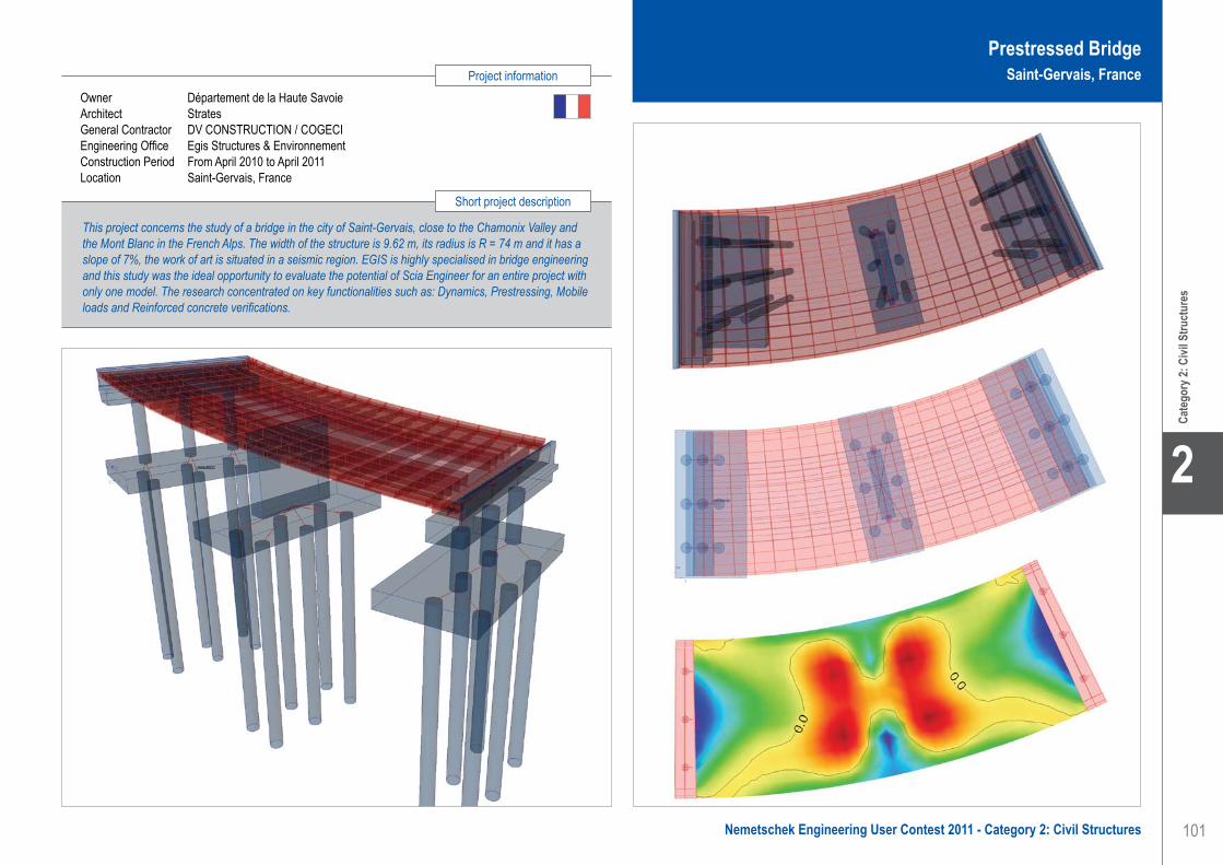
101
Project information
Short project description
Nemetschek Engineering User Contest 2011 - Category 2: Civil Structures
Cate
gory
2: C
ivil S
truct
ures
2
Owner Département de la Haute SavoieArchitect StratesGeneral Contractor DV CONSTRUCTION / COGECIEngineering Office Egis Structures & Environnement Construction Period From April 2010 to April 2011Location Saint-Gervais, France
This project concerns the study of a bridge in the city of Saint-Gervais, close to the Chamonix Valley and the Mont Blanc in the French Alps. The width of the structure is 9.62 m, its radius is R = 74 m and it has a slope of 7%, the work of art is situated in a seismic region. EGIS is highly specialised in bridge engineering and this study was the ideal opportunity to evaluate the potential of Scia Engineer for an entire project with only one model. The research concentrated on key functionalities such as: Dynamics, Prestressing, Mobile loads and Reinforced concrete verifications.
Prestressed BridgeSaint-Gervais, France
EGIS Structures & Environnement . . . . . . . . . . . . . . . . . . . . . . . Prestressed Bridge - Saint-Gervais, France
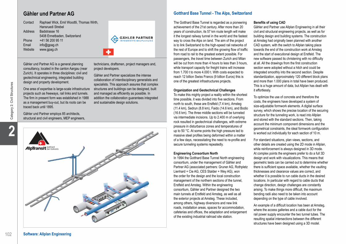
102
2
Cate
gory
2: C
ivil S
truct
ures
Gähler und Partner AGContact Raphael Wick, Emil Woodtli, Thomas Wirth,
Hansruedi StrebelAddress Badstrasse 16 5408 Ennetbaden, SwitzerlandPhone +41 56 200 95 11Email [email protected] www.gpag.ch
Gotthard Base Tunnel - The Alps, Switzerland
The Gotthard Base Tunnel is regarded as a pioneering achievement of the 21st century. After more than 20 years of construction, its 57 km route length will make it the longest railway tunnel in the world and the fastest way to cross the Alps on land. The aim of the project is to link Switzerland to the high-speed rail networks of the rest of Europe and to shift the growing flow of traffic from road to rail to the greatest extent possible. For passengers, the travel time between Zurich and Milan will be cut from more than 4 hours to less than 3 hours, while transport capacity for freight trains will increase from 1.700 t to more 4.000 t. With costs expected to reach 12 billion Swiss Francs (9 billion Euros) this is one of the greatest infrastructures projects.
Organization and Geotechnical ChallengesTo make this mighty project a reality within the shortest time possible, it was divided into five sections. From north to south, these are Erstfeld (7.4 km), Amsteg (11.4 km), Sedrun (8.8 km), Faido (14.6 km), and Bodio (16.6 km). The three middle sections will be tunneled via intermediate incisions. Up to 2.400 m of overlying rock resulted in geotechnical challenges, with extreme pressure in disturbance zones and temperatures of up to 50 °C. At some points the high pressure led to massive steel profiles being deformed within a matter of a few days, necessitating the need to re-profile and secure tunneling systems repeatedly.
Engineering Consortium NorthIn 1994 the Gotthard Base Tunnel North engineering consortium, under the management of Gähler and Partner AG (associated partners: Gruner AG, Rothpletz Lienhard + Cie AG, CES Stalder + Wey AG), won the order for the design and the local construction management of the northern sections of the tunnel, Erstfeld and Amsteg. Within the engineering consortium, Gähler and Partner designed the two main tunnels at Erstfeld and Amsteg, as well as all the exterior projects at Amsteg. These included, among others, highway diversions and new link roads, installation areas, spaces for accommodation, cafeterias and offices, the adaptation and enlargement of the existing industrial railroad site station.
Benefits of using CADGähler and Partner use Allplan Engineering in all their civil and structural engineering projects, as well as for building design and building systems. The construction at Amsteg had originally been planned with another CAD system, with the switch to Allplan taking place towards the end of the construction work at Amsteg and the start of executional design at Erstfeld. The new software passed its christening with no difficulty at all. All the drawings from the first construction section were adopted without a hitch and could be integrated smoothly into the second section. Despite standardization, approximately 120 different block plans and more than 1.000 plans in total have been produced. This is a huge amount of data, but Allplan has dealt with it effortlessly.
To optimize the use of concrete and therefore the costs, the engineers have developed a system of size-adjustable formwork elements. A digital surface survey, which shows the precise location of the securing structure for the tunneling work, is read into Allplan and stored with the standard sections. Then, taking account the minimum component dimensions and the geometrical constraints, the ideal formwork configuration is worked out individually for each section of 10 m.
For standard situations, plan views, sections, and other details are created using the 2D mode in Allplan, while reinforcement is always designed in 3D mode. At complex points the engineers prefer to do a full 3D design and work with visualizations. This means that geometric tests can be carried out to determine whether there is sufficient space available, whether the vaulting thicknesses and clearance values are correct, and whether it is possible to run cable ducts in the desired locations. In particular with regard to cable ducts that change direction, design challenges are constantly arising. To make things more difficult, the maximum bending radii also need to be taken into account depending on the type of cable involved.
An example of a difficult location has been at Amsteg, where the access galleries and a cable duct for the rail power supply encounter the two tunnel tubes. The resulting spatial intersections between the different structures have been designed using a 3D model.
Gähler und Partner AG is a general planning consultancy, located in the canton Aargau (near Zurich). It operates in three disciplines: civil and geotechnical engineering, integrated building design and property development.
One area of expertise is large-scale infrastructure projects such as freeways, rail links and tunnels.The firm in present form was established in 1988 as a management buy-out, but its roots can be traced back until 1895.
Gähler und Partner employs 85 architects, structural and civil engineers, MEP engineers,
technicians, draftsmen, project managers and, project developers.
Gähler and Partner specializes the intense collaboration of interdisciplinary generalists and specialists. This approach assures that complex structures and buildings can be designed, built and managed as efficiently as possible. In addition the collaboration guarantees integrated and sustainable design solutions.
Software: Allplan Engineering
Gähler und Partner AG . . . . . . . . . . . . . . . . . . . . . . . . . . . . . . . . Gotthard Base Tunnel - The Alps, Switzerland

103
Project information
Short project description
Nemetschek Engineering User Contest 2011 - Category 2: Civil Structures
Cate
gory
2: C
ivil S
truct
ures
2
Gotthard Base TunnelThe Alps, Switzerland
Owner AlpTransit Gotthard AGGeneral Contractor AGN ARGE Gotthard-Basistunnel NordEngineering Office Gähler und Partner AG (Ingenieurgemeinschaft Gotthard-Basistunnel Nord)Construction Period From April 1996 to December 2016Location Erstfeld - Bodio, Switzerland
The “Gotthard Base Tunnel” is a railway tunnel beneath the Alps in Switzerland. With a route length of 57 kilometres, it is the world’s longest tunnel. By 2016, after more than 20 years of construction, costs are expected to reach 12 billion Swiss Francs (9 billion Euro). It bypasses the old winding mountain route across the Saint-Gotthard Massif and establishes a direct route suitable for high speed and heavy freight trains. Together with other tunnels, it will become the fastest way to cross the Alps on land. High speed trains will be travelling at up to 250 km/h through the tunnel and cut the 4 h travel time from Zurich to Milan by an hour.
Gähler und Partner AG . . . . . . . . . . . . . . . . . . . . . . . . . . . . . . . . Gotthard Base Tunnel - The Alps, Switzerland

104
2
Cate
gory
2: C
ivil S
truct
ures
Software: Scia Engineer
Feasibility Study of Vilvoorde Viaduct - Brussels, Belgium
This project concerns a feasibility study of an extension of the capacity of the Vilvoorde viaduct. Currently there are three lanes in each direction. The study examined the possibility for four lanes in each direction. The fatigue phenomenon was also investigated.
GeometryThe Vilvoorde viaduct consists of two adjacent bridges, each 20 meter wide. The total length of each bridge is about 1.700 meter. Coming from the direction of Strombeek-Bever, four parts can be distinguished: • Part A consists of a composite steel - concrete
structure with a total length of 288 meter. • Part B consists of a steel caisson with a steel
orthotropic deck. This part has a total length of about 880 meter and contains the largest span of 162 meter.
• Part C with an identical structure as part A has a total length of 400 meter.
• Part D is a superstructure of prestressed concrete with a total length of 130 meter.
Parts A and B were investigated in the study. Part A consists of 5 spans of 58 meter.
The supporting structure is a composite beam composed of:• A steel substructure composed of two main girders
and 17 cross beams. The main girders have a height of 3.2 meter and were prestressed during construction phase.
• A concrete slab with a thickness of 220 millimeter.
Part B consists of a steel caisson with an orthotropic steel deck. The steel caisson has a width of 8 meter and a height of 5.6 meter. On each side of the box, the deck has a cantilever of 6 meter. The part B is a hyper static structure from pillar 6 till pillar 13 and has a total length of 880 meter. The spans vary from 90 to 162 meter. Part B is fully curved with a radius of 700 meter.
The viaduct was built in 1977 and was originally designed for 4 lanes. Until now, with the exception of a short period for maintenance, there were only 3 lanes on the viaduct. Meanwhile, the design methods have evolved to take into account the busy traffic and the heavier axle loads and there is a better understanding of the fatigue phenomenon.
Part AFor part A two different models were made in Scia Engineer. A first model was to investigate the time dependent effects of the concrete. A second model was to analyze the mobile loads. The model was made with 2D plate elements.
Part BPart B of the bridge was also modelled in Scia Engineer. To make a workable model that was also sufficiently accurate, different levels of refinement were used. For the area under investigation the level of refinement was high. However for parts further away from the investigated zone, the level of refinement was reduced, for example by modelling the longitudinal stiffeners in the thickness of the plate. It was always verified that the self-weight of the structure was correct. The validity of the various refinements was separately tested in different models.
Grontmij is a multidisciplinary consulting and engineering firm for sustainable planning & design, transportation & mobility and water, energy & industry.
From a future-oriented vision, we provide quality advice and we design creative plans and projects. That way, we contribute to a better housing, working and living environment. It’s our ambition to be the best sustainable consulting and engineering firm and to add value, from A to Z, to advice, study, design, engineering, execution and management of projects.
As a publicly listed company, we are active in 350 offices with some 11.000 experts in 50 countries, and we are leaders in Europe.
Grontmij operates within three business lines, namely: Water & Energy, Transportation & Mobility and Planning & Design. These reflect the long term external market drivers such as climate change, population growth and urbanisation across the world.
GrontmijContact Anne-Caroline Kiekens, Bart Van de SijpeAddress A. Gossetlaan 28A 1702 Groot-Bijgaarden, BelgiumPhone +32 2 383 06 40Email [email protected] www.grontmij.be
Grontmij . . . . . . . . . . . . . . . . . . . . . . . . . . . . . . . . . . . . . . . . . . . . Feasibility Study of Vilvoorde Viaduct - Brussels, Belgium

105
Project information
Short project description
Nemetschek Engineering User Contest 2011 - Category 2: Civil Structures
Cate
gory
2: C
ivil S
truct
ures
2
Owner Belgian stateEngineering Office GrontmijConstruction Period From 1977 to 1978Location Vilvoorde, Belgium
The project is about the viaduct of Vilvoorde, part of the R0 Brussels beltway and built in 1977. It concerns a feasibility study of an extension of the capacity of the Vilvoorde viaduct. The study examined the possibility for four lanes in each direction and investigated the fatigue phenomenon. Parts A and B were modelled in Scia Engineer. Part A consists of a composite steel - concrete structure with a total length of 288 meter. Part B consists of a steel caisson with a steel orthotropic deck. This part has a total length of about 880 meter and contains the largest span of 162 meter.
Feasibility Study of Vilvoorde ViaductBrussels, Belgium
Grontmij . . . . . . . . . . . . . . . . . . . . . . . . . . . . . . . . . . . . . . . . . . . . Feasibility Study of Vilvoorde Viaduct - Brussels, Belgium
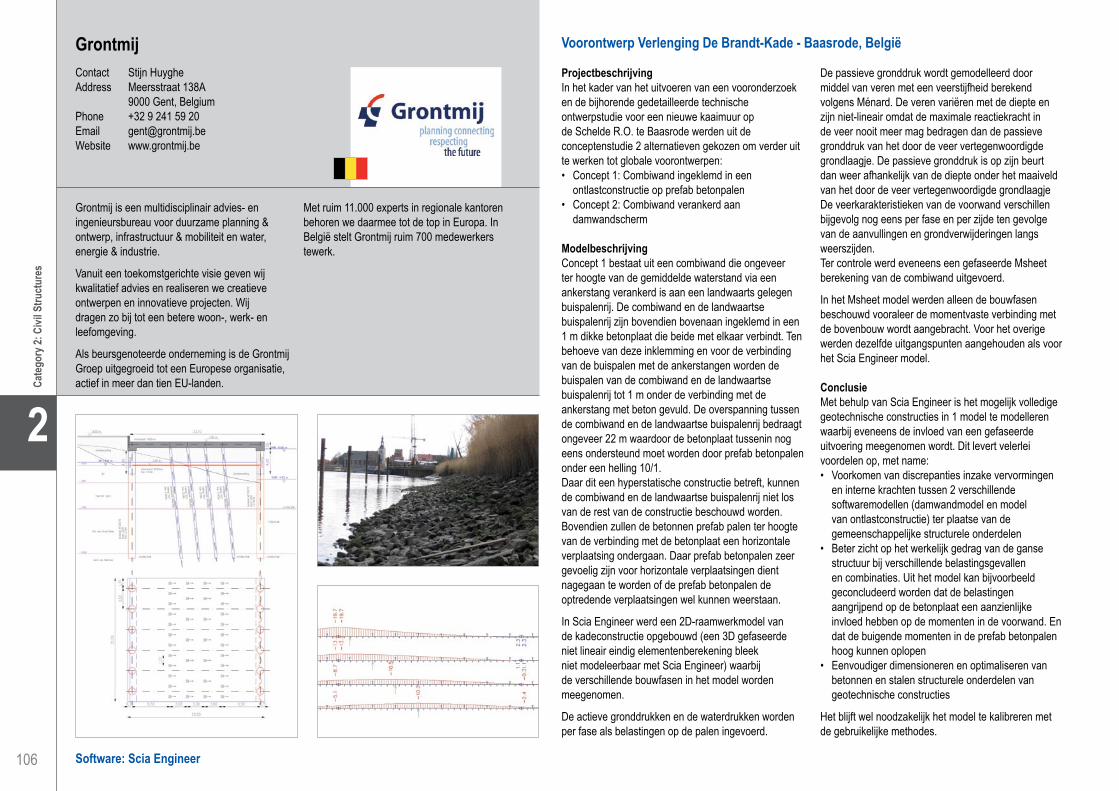
106
2
Cate
gory
2: C
ivil S
truct
ures
Software: Scia Engineer
Grontmij . . . . . . . . . . . . . . . . . . . . . . . . . . . . . . . . . . . . . . . . . . . . Preliminary Design of Extension De Brandt-Kade - Baasrode, Belgium
Voorontwerp Verlenging De Brandt-Kade - Baasrode, België
Projectbeschrijving In het kader van het uitvoeren van een vooronderzoek en de bijhorende gedetailleerde technische ontwerpstudie voor een nieuwe kaaimuur op de Schelde R.O. te Baasrode werden uit de conceptenstudie 2 alternatieven gekozen om verder uit te werken tot globale voorontwerpen:• Concept 1: Combiwand ingeklemd in een
ontlastconstructie op prefab betonpalen • Concept 2: Combiwand verankerd aan
damwandscherm
Modelbeschrijving Concept 1 bestaat uit een combiwand die ongeveer ter hoogte van de gemiddelde waterstand via een ankerstang verankerd is aan een landwaarts gelegen buispalenrij. De combiwand en de landwaartse buispalenrij zijn bovendien bovenaan ingeklemd in een 1 m dikke betonplaat die beide met elkaar verbindt. Ten behoeve van deze inklemming en voor de verbinding van de buispalen met de ankerstangen worden de buispalen van de combiwand en de landwaartse buispalenrij tot 1 m onder de verbinding met de ankerstang met beton gevuld. De overspanning tussen de combiwand en de landwaartse buispalenrij bedraagt ongeveer 22 m waardoor de betonplaat tussenin nog eens ondersteund moet worden door prefab betonpalen onder een helling 10/1.Daar dit een hyperstatische constructie betreft, kunnen de combiwand en de landwaartse buispalenrij niet los van de rest van de constructie beschouwd worden. Bovendien zullen de betonnen prefab palen ter hoogte van de verbinding met de betonplaat een horizontale verplaatsing ondergaan. Daar prefab betonpalen zeer gevoelig zijn voor horizontale verplaatsingen dient nagegaan te worden of de prefab betonpalen de optredende verplaatsingen wel kunnen weerstaan.
In Scia Engineer werd een 2D-raamwerkmodel van de kadeconstructie opgebouwd (een 3D gefaseerde niet lineair eindig elementenberekening bleek niet modeleerbaar met Scia Engineer) waarbij de verschillende bouwfasen in het model worden meegenomen.
De actieve gronddrukken en de waterdrukken worden per fase als belastingen op de palen ingevoerd.
De passieve gronddruk wordt gemodelleerd door middel van veren met een veerstijfheid berekend volgens Ménard. De veren variëren met de diepte en zijn niet-lineair omdat de maximale reactiekracht in de veer nooit meer mag bedragen dan de passieve gronddruk van het door de veer vertegenwoordigde grondlaagje. De passieve gronddruk is op zijn beurt dan weer afhankelijk van de diepte onder het maaiveld van het door de veer vertegenwoordigde grondlaagje De veerkarakteristieken van de voorwand verschillen bijgevolg nog eens per fase en per zijde ten gevolge van de aanvullingen en grondverwijderingen langs weerszijden.Ter controle werd eveneens een gefaseerde Msheet berekening van de combiwand uitgevoerd.
In het Msheet model werden alleen de bouwfasen beschouwd vooraleer de momentvaste verbinding met de bovenbouw wordt aangebracht. Voor het overige werden dezelfde uitgangspunten aangehouden als voor het Scia Engineer model.
ConclusieMet behulp van Scia Engineer is het mogelijk volledige geotechnische constructies in 1 model te modelleren waarbij eveneens de invloed van een gefaseerde uitvoering meegenomen wordt. Dit levert velerlei voordelen op, met name:• Voorkomen van discrepanties inzake vervormingen
en interne krachten tussen 2 verschillende softwaremodellen (damwandmodel en model van ontlastconstructie) ter plaatse van de gemeenschappelijke structurele onderdelen
• Beter zicht op het werkelijk gedrag van de ganse structuur bij verschillende belastingsgevallen en combinaties. Uit het model kan bijvoorbeeld geconcludeerd worden dat de belastingen aangrijpend op de betonplaat een aanzienlijke invloed hebben op de momenten in de voorwand. En dat de buigende momenten in de prefab betonpalen hoog kunnen oplopen
• Eenvoudiger dimensioneren en optimaliseren van betonnen en stalen structurele onderdelen van geotechnische constructies
Het blijft wel noodzakelijk het model te kalibreren met de gebruikelijke methodes.
Grontmij is een multidisciplinair advies- en ingenieursbureau voor duurzame planning & ontwerp, infrastructuur & mobiliteit en water, energie & industrie.
Vanuit een toekomstgerichte visie geven wij kwalitatief advies en realiseren we creatieve ontwerpen en innovatieve projecten. Wij dragen zo bij tot een betere woon-, werk- en leefomgeving.
Als beursgenoteerde onderneming is de Grontmij Groep uitgegroeid tot een Europese organisatie, actief in meer dan tien EU-landen.
Met ruim 11.000 experts in regionale kantoren behoren we daarmee tot de top in Europa. In België stelt Grontmij ruim 700 medewerkers tewerk.
GrontmijContact Stijn HuygheAddress Meersstraat 138A 9000 Gent, BelgiumPhone +32 9 241 59 20Email [email protected] Website www.grontmij.be

107
Project information
Short project description
Nemetschek Engineering User Contest 2011 - Category 2: Civil Structures
Cate
gory
2: C
ivil S
truct
ures
2
Preliminary Design of Extension De Brandt-KadeBaasrode, Belgium
Grontmij . . . . . . . . . . . . . . . . . . . . . . . . . . . . . . . . . . . . . . . . . . . . Preliminary Design of Extension De Brandt-Kade - Baasrode, Belgium
Owner WenZ - De BrandtEngineering Office GrontmijConstruction Period Pre-design onlyLocation Baasrode, Belgium
For the elongation of an existing quay wall along the Scheldt, 2 different solutions were chosen out of 5 concepts, namely a combi wall anchored to a sheet pile wall and a combi wall embedded in a relieving platform. The relieving platform is highly influenced by the different construction stages and is supported by non-linear spring-supports representing the soil. The Scia Engineer model clearly shows the influence on the front wall of the loads acting on the relieving platform thus proving the necessity of a model including all structural members for a similar hyperstatic quay wall structure.

108
2
Cate
gory
2: C
ivil S
truct
ures
Gaardeniersbrug voor Fietsers en Voetgangers - Gent, België
Korte beschrijvingDe Gaardeniersbrug te Gent is een samenstel van enerzijds een betonnen trambrug (ter plaatse nagespannen) en anderzijds een stalen fietsers-en voetgangersbrug. De beide bruggen overspannen de Gasmeterlaan, het Verbindingskanaal en de Nieuwe Vaart.
De fietsers-en voetgangersbrug verbindt de fietsas ‘Westerringspoor’ met het centrum van Gent; de trambrug vormt de verbinding tussen de stelplaats ‘Wissenhage’ van de openbare vervoermaatschappij De Lijn en het stadscentrum. Voor de fietsers- en voetgangersbrug is de opdrachtgever het college van Burgemeester en schepenen van de Stad Gent; voor de trambrug is dat de Vlaamse Vervoermaatschappij De Lijn.
De pijlers van de fietsbrug hebben allemaal dezelfde kegelvorm; ze verschillen door de inclinatie en de hoogte boven het maaiveld. Aan de pijlers van de fietsbrug is de bovenleiding van de tram opgehangen, waardoor de beide bruggen visueel en functioneel verbonden zijn.
De fietsbrug bestaat uit ten eerste de fietsbrug zelf (aangeduid als ‘primaire fietsbrug’) en een helling daar naar toe (aangeduid als secundaire fietsbrug).
Het stalen gedeelte van de primaire fietsbrug is schematisch een ligger met 18 overspanningen van elk 20 m, in totaal dus 360 m. Door het invoeren van voegen is deze 360 m verdeeld in 7 stukken van respectievelijk 37 m, 5 x 60 m, 23 m. Aan de voegen zijn neopreenopleggingen voorzien.
Het dragende element van de fietsbrug is een stalen buis. Op deze buis zijn stalen vinnen geplaatst die het wegdek dragen; de vinnen maken met de as van de buis een hoek van circa 45°.
De pijlers zijn ingeklemd op betonnen funderingsvoeten; de voeten zijn op palen gefundeerd.
Totaal staalverbruik (constructiestaal S235 en S355, voornamelijk plaatstaal): 485 ton.
BerekeningenVoor de studie werden, in Scia Engineer, verschillende modellen gebouwd, met verschillende graad van detaillering.
Om te beginnen werd een driedimensionaal stavenmodel voor het bepalen van de krachtswerkingen op de fundering en de globale staalspanningscontrole gemaakt.
Daarnaast werden driedimensionale eindige elementenmodellen met vlakke elementen en ribben gebouwd, dit voor de studie van de vervormingen en de eigenfrequentie.
Voor de verbindingen van de masten met de funderingsvoeten werden driedimensionale eindige elementenmodellen gebruikt met schaalelementen.
UitvoeringDe draagbuis, de vinnen en de dekken werden in het atelier gelast tot gehelen van 20 m lengte, met andere woorden de overspanningslengte. Ook de masten werden in hun geheel op de werf gebracht. De onderdelen werden op de werf aaneengelast.
De firma Victor Buyck Steel Construction (Eeklo) zorgde voor de uitvoering, in onderaanneming van enerzijds A. Moens nv en anderzijds Besix nv.
HistoriekHet Ingenieursbureau G. Derveaux nv (ID) werd opgericht in 1958 door ir. Godfried Derveaux en is uitgegroeid tot één van de meest belangrijke onafhankelijke bureaus van België. Vandaag wordt het bureau geleid door ir. Jan Derveaux (zoon van).
WerkterreinID is gespecialiseerd in het ontwerpen van bouwkundige en industriële projecten, zowel op het vlak van architectuur, stabiliteit als technische uitrusting.
RealisatiesWereldwijd, op basis van totaal- of deelopdrachten verstrekt aan ID:• honderden bruggen van staal, gewapend beton,
voorgespannen beton• meer dan 4.000.000 m² aan utilitaire gebouwen• meer dan 10.000.000 m³ aan
industriegebouwen• parkeerinfrastructuur voor meer dan 9.000
autostandplaatsen in ondergrondse parkings• meer dan 800 andere constructies: silo’s,
tunnels en andere ondergrondse werken, parkeergebouwen, restauratiewerken
Ing. Bureau G. Derveaux nvContact Paul Van DriesscheAddress De Braempoort Brabantdam 33E 9000 Gent, BelgiumPhone +32 92330011Email [email protected]
Software: Scia Engineer
Ing. Bureau G. Derveaux nv . . . . . . . . . . . . . . . . . . . . . . . . . . . . Bicycle and Pedestrian Bridge - Ghent, Belgium

109
Project information
Short project description
Nemetschek Engineering User Contest 2011 - Category 2: Civil Structures
Cate
gory
2: C
ivil S
truct
ures
2
This project is about the Gaardeniersbrug in Ghent. It is a combination of both a concrete bridge for trams (post-tensioned on site) and a steel ‘bicycle and pedestrian’ bridge. The pillars of the bike bridge are all shaped as identical cones; they differ regarding the inclination and height above ground level. The overhead lines for the trams are suspended on the pillars of the cyclist’s bridge, which link both bridges visually and functionally. The supporting beam is a steel pipe; it has steel fins, which are forming an angle of 45° with the axis of the tube, and which are supporting the road.
Owner Stad GentArchitect Ing. bureau G. Derveaux nvGeneral Contractor Besix-Vlaanderen (Gent) - A. Moens (Meise)Engineering Office Ing. bureau G. Derveaux nvConstruction Period From March 2007 to December 2009Location Ghent, Belgium
Bicycle and Pedestrian BridgeGhent, Belgium
Ing. Bureau G. Derveaux nv . . . . . . . . . . . . . . . . . . . . . . . . . . . . Bicycle and Pedestrian Bridge - Ghent, Belgium

110
2
Cate
gory
2: C
ivil S
truct
ures
Ingenieursbureau Oranjewoud B.V.Contact ir. George Bitter, ing. Hans ZuidemaAddress Postbus 10044 1301 AA Almere, The NetherlandsPhone +31 36 5308000Email [email protected] www.oranjewoud.nl
Bridge Renovation Project - Dordrecht, The Netherlands
As part of the project “bridge renovation”, a project of the Netherlands Directorate-General for Public Works and Water Management (RWS), potential measures are under consideration for drawbridges exhibiting fatigue issues.
In addition to total replacement of the bridge decks, another option would be to reinforce the existing decks by gluing a steel plate onto the slow lanes. The required remaining service life of these bridges should be 30 years.
One of the bridges under consideration is the Wantij bridge on the Dordrecht ring road (N3).
Deck structureThe orthotropic deck is made from a 12 mm thick steel plate. This plate is supported by stiffeners spaced 600 mm centre-to-centre. These are trapezoidal profiles made from 6 mm sheet material, with a height of 250 mm and a width of 300 mm. The profiles are welded between the cross girders.
The deck is reinforced by a 6 mm thick steel plate that is glued to the ‘slow lane’. This is the right-hand lane of the main roadway. This lane will be subjected to the heaviest loads from cargo traffic.
The stiffeners are supported by six cross girders. These are supported by two main girders which extend to the counterweight. The spacing of the cross girders is 2.905 mm.
The main girders are manufactured from composite I-beams and have a structural height of approximately 2.05 m at the main bearing, decreasing to 1.30 m at the roadway. The cross beams are also designed as a composite I-beam.
The main bearings of the deck are positioned both on the inside and outside of the main girders. This limits the torque in the main girders. The deck has a span of 15.5 m and a width of approximately 8.5 m. The width of the deck is 15.2 m.
Use of Scia EngineerA global model has been built to calculate the strength, stiffness and fatigue of the main steel structure and the deck superstructure.
Three models were created: 1. Strength and fatigue calculation model for a
reinforced deck outside of the motion cycle (due to traffic).
2. Fatigue calculation model for an existing deck outside of the motion cycle, to determine fatigue damage up to the present day.
3. Fatigue calculation model for a reinforced deck outside of the motion cycle, to determine future fatigue damage.
Furthermore, local models are created to calculate the strength and fatigue of the glue line between the reinforcing plate and the deck plate of the bridge.
Fatigue tests were performed by TNO and Lightweight structures BV to determine the fatigue strength of the glue line. To determine the Sigma (N)-curve as a boundary value we created a Scia Engineer model of the test setup and used the test results.
Results:• The strength and stability of the structure were
checked using the steel code check in Scia Engineer. • A stiffness control is performed.• The glue line is checked with the local models. To
this end the results of Scia Engineer are compared with the results from the fatigue tests.
Oranjewoud: A world of opportunity!Comfortable living, work, travel and recreation are only possible with a proper understanding of space. Oranjewoud’s fields of activity consequently range from urban development, mobility, construction and property to rural development, water, the environment, safety, sport and recreation. We operate in the Netherlands and on an international scale too. Oranjewoud was a major force in land management under Frisian management some 60 years ago. Our organisation has developed into an all-
round partner and is much more than just an engineering consultancy.
MissionOranjewoud aims to be a leading partner in the development and application of sustainable and integral solutions relating to all aspects of our living environment, such as home, work, recreation, mobility and the environment.
Core valuesEnterprising, People-oriented, Development, and Character.
Software: Scia Engineer
Ingenieursbureau Oranjewoud B.V.. . . . . . . . . . . . . . . . . . . . . . . Bridge Renovation Project - Dordrecht, The Netherlands

111
Project information
Short project description
Nemetschek Engineering User Contest 2011 - Category 2: Civil Structures
Cate
gory
2: C
ivil S
truct
ures
2
Owner Directorate-General for Public Works and Water Management (RWS)Engineering Office Ingenieursbureau Oranjewoud B.V.Construction Period From 2011 to 2012Location Dordrecht, The Netherlands
The project is about the strengthening or replacing of 3 bridges. In addition to total replacement of the bridge decks, another option would be to reinforce the existing decks by gluing a steel plate onto the slow lanes. A global model has been built to calculate the strength, stiffness and fatigue of the main steel structure and the deck superstructure. Furthermore, local models are created to calculate the strength and fatigue of the glue line between the reinforced plate and the deck plate of the bridge. To determine the Sigma(N)-curve as a boundary value we created a Scia Engineer model of the fatigue test setup.
Bridge Renovation Project Dordrecht, The Netherlands
Ingenieursbureau Oranjewoud B.V.. . . . . . . . . . . . . . . . . . . . . . . Bridge Renovation Project - Dordrecht, The Netherlands

112
2
Cate
gory
2: C
ivil S
truct
ures
Software: Scia Engineer
Footbridge De Gilden - Dronten, The Netherlands
IntroductionA new residential area is being realized on the west side of Dronten: De Gilden. The bridges in the district were designed by Buro MA.AN from Rotterdam, which was inspired by the large modern wind turbines in the polders around Dronten.
This steel footbridge over the central waterway is part of the main access route for pedestrians, bikes and other slow vehicles.
The design of the steel footbridge is in colour and shape consistent with the distinctive design of modern wind turbines. White-coated steel is used and the shape of the bridge is derived from the tapered blades of a modern wind turbine. The wing sections are placed against each other and have narrow ends that are directed towards the abutments and seem to just barely touch the banks of the canal. This design makes the bridge look like as if it is floating above the water’s surface. At the centre of the waterway the cantilevered footpath is 0.5 m higher than the adjacent cycle path. This creates a nice lookout point.
Description of the footbridgeThe bridge consists of three spans of 21.85 m, 17.65 m and 23.0 m. The width of the bridge deck varies from 6.70 m up to a maximum of 7.70 m.
The bridge will be made as a continuous steel box girder across 4 supports. The top flange acts as the floor of the bridge. This orthotropic deck consists of a 12 mm thick steel plate stiffened with longitudinal T-shaped stiffeners which are welded to the lower side of the plate. The load is transferred through the stiffeners and the transverse cross girders (approximately 4 m centre-to-centre) onto the side walls. The crossbeams at the location of the supports have the same height as the box girder. This ensures sufficient stiffness to transfer the loads onto the substructure.
The substructure consists of two abutments and two identical pillars made of cast-in-place reinforced concrete, which are founded on precast prestressed concrete piles.
The bridge is slidingly supported at the abutments to enable thermal deformation of the end spans. At the pillars however, rocker bearings are being used, so longitudinal deformations of the middle span will therefore lead to horizontal loads on the pillars.
Use of Scia EngineerDue to the complexity of the design, it was necessary to create a 3D model. The bridge contours were drawn in Autodesk Inventor. AutoCad was used to create a 3D drawing in which internal components such as stiffeners and cross girders were added. Subsequently the 3D model was imported into Scia Engineer. In this program, the plate and rod elements could easily be added. The concrete substructure was not implemented in the FEM model.
The bridge was checked on strength and stiffness. Fatigue is not an issue for a footbridge.
The loads and load combinations were taken from NEN6706 - Traffic loads on bridges. Besides dead load, the following loads apply: a uniformly distributed load of 5 kN/m2 (crowd) or a service vehicle with a total weight of 50 kN, wind load, differential support settlement and loads due to uneven heating of the structure.
The model was initially intended for the global strength and stiffness check of the structure and to determine the loads on the substructure. In the detailing phase the model can easily be expanded in order to check the stability of the various elements.
Ingenieursbureau Oranjewoud B.V.. . . . . . . . . . . . . . . . . . . . . . . Footbridge De Gilden - Dronten, The Netherlands
Oranjewoud: A world of opportunity!Comfortable living, work, travel and recreation are only possible with a proper understanding of space. Oranjewoud’s fields of activity consequently range from urban development, mobility, construction and property to rural development, water, the environment, safety, sport and recreation. We operate in the Netherlands and on an international scale too. Oranjewoud was a major force in land management under Frisian management some 60 years ago. Our organisation has developed into an all-
round partner and is much more than just an engineering consultancy.
MissionOranjewoud aims to be a leading partner in the development and application of sustainable and integral solutions relating to all aspects of our living environment, such as home, work, recreation, mobility and the environment.
Core valuesEnterprising, People-oriented, Development, and Character.
Ingenieursbureau Oranjewoud B.V.Contact ing. Hans Zuidema, ing. Peter MinnesmaAddress Postbus 24 8440 AA Heerenveen, The NetherlandsPhone +31 513 634567Email [email protected] www.oranjewoud.nl
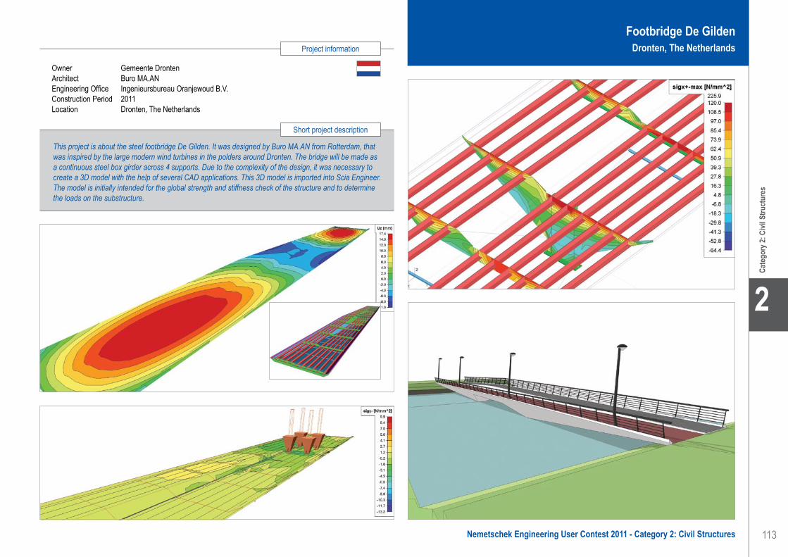
113
Project information
Short project description
Nemetschek Engineering User Contest 2011 - Category 2: Civil Structures
Cate
gory
2: C
ivil S
truct
ures
2
This project is about the steel footbridge De Gilden. It was designed by Buro MA.AN from Rotterdam, that was inspired by the large modern wind turbines in the polders around Dronten. The bridge will be made as a continuous steel box girder across 4 supports. Due to the complexity of the design, it was necessary to create a 3D model with the help of several CAD applications. This 3D model is imported into Scia Engineer. The model is initially intended for the global strength and stiffness check of the structure and to determine the loads on the substructure.
Owner Gemeente DrontenArchitect Buro MA.ANEngineering Office Ingenieursbureau Oranjewoud B.V.Construction Period 2011Location Dronten, The Netherlands
Footbridge De GildenDronten, The Netherlands
Ingenieursbureau Oranjewoud B.V.. . . . . . . . . . . . . . . . . . . . . . . Footbridge De Gilden - Dronten, The Netherlands

114
2
Cate
gory
2: C
ivil S
truct
ures
Iv-Infra b.v.Contact Robert ErmstrangAddress Fultonbaan 30 3439NE Nieuwegein, The NetherlandsPhone +31 30 6023030Email [email protected] www.iv-groep.nl
Fly-Over - Haarlem, Nederland
InleidingProRail realiseert in opdracht van de gemeente Haarlem het project Fly-over Haarlem. Het project Fly-over is onderdeel van het programma Spoorzone waarin wonen, werken en bereikbaarheid samenkomen. De economische en sociale ontwikkelingen in het gebied rond het spoor in Haarlem zijn in het Masterplan Spoorzone op elkaar afgestemd. De fly-over zorgt voor een rechtstreekse verbinding tussen de A200 (Amsterdamsevaart) en de Waarderpolder. Hiermee wordt enerzijds het bedrijventerrein beter ontsloten en anderzijds worden de woonwijken in Haarlem-Noord en de Zuiderpolder ontlast van veel doorgaand verkeer. De fly-over kruist zowel de A200 als de spoorlijn. De fly-over wordt zodanig gerealiseerd dat een toekomstige uitbreiding van 2 naar 4 sporen onder de fly-over op een later tijdstip gerealiseerd kan worden.
De fly-over heeft een totale lengte van circa 200 meter, die over 5 overspanningen verdeeld is. De breedte van het kunstwerk is gelijk aan circa 20 meter. Het dek van het kunstwerk wordt gebouwd met behulp van prefab betonnen kokers die zowel in langs- als in dwarsrichting worden nagespannen. De randconstructie van het dek wordt uitgevoerd met glasvezelversterkte kunststofelementen.
Beschrijving werkzaamhedenIn opdracht van Ballast Nedam Infra noord West maakt Iv-Infra, buiten de gehele engineeringscoördinatie, het uitvoeringsontwerp voor de fundering, grondkerende constructies, betonnen pijlers en de landhoofden. Fascinerend aan het project zijn de complexe architectonisch vormgegeven pijlers. Gezien de speciale vorm van de pijlers is in overleg met de aannemer besloten om de vorm en de wapening van de pijlers in Allplan uit te tekenen. Het door Iv-Infra getekende 3D model van de pijler (vorm en wapening) is vervolgens binnen het project gebruikt voor:• Het maken van de kist. Om de kist te maken
heeft de bouwer van de kist van ons het model ter beschikking gekregen. We hebben het model hiervoor wel eerst, via een extern programma, moeten converteren naar een Solid Edge bestand.
• Het buigen en knippen van de wapening. Iv-Infra heeft alle buigstaten van de wapening aan de
leverancier van de wapening verstrekt. Op basis van deze buigstaten heeft de vlechter zijn wapening geknipt en gebogen.
Door hetzelfde model te gebruiken voor het maken van de kist, het vlechten van de wapening en het tekenen van de betonvorm is het risico voor de aannemer, namelijk dat verschillende zaken niet op elkaar passen, tot een minimum beperkt.
De pijlerDe pijler komt in totaal 4 keer voor. Het totale volume van een zo’n pijler komt neer op ongeveer 122 m3.Het opbouwen van de pijler in 3D was een project op zich. Er zit bijna geen recht stukje in en alle gebogen vlakken zijn opgebouwd uit verschillende kleine stukjes met verschillende stralen.
Uiteindelijk is de pijler in 2 stukken opgedeeld en elk stuk is behandeld als zijnde een op zijn kant liggend dek. Zo konden door op een aparte manier gebruik te maken van de Bruggen- en Tunnelmodeller de 2 helften gemodelleerd en daarna op elkaar aangesloten worden.
Het gat in het lichaam van de pijler is er daarna op een normale manier uitgesneden, maar de afrondingen van dit gat zijn ook weer met de Bruggen- en Tunnelmodeller gerealiseerd.
Ook het wapenen van deze pijler vormde een uitdaging met al die verlopende vlakken, dit bleek achteraf wel arbeidsintensief, maar niet zo moeilijk. Dit komt ook door het feit dat in Allplan visueel meteen controleerbaar is of er conflicten zijn met de wapening en/of kist, hetzij in animatiemodus of met behulp van enkele snel gemaakte snedes en aanzichten.
Doordat deze snedes en aanzichten associatief zijn kan men meteen in real time zien wat er gebeurt als er iets wordt aangepast in het model of in de wapening. De wapeningsleverancier was ook erg te spreken over de aangeleverde buigstaat, welke bijna volledig automatisch met Allplan gegenereerd kan worden.
Iv-Infra is onderdeel van Iv-Groep, een groep van wereldwijd opererende advies- en ingenieursbureaus met 800 medewerkers.Iv-Groep biedt een multidisciplinair dienstenpakket op de markten Gebouwen en Constructies, Industrie en Energie, Infrastructuur en Havens, Olie en Gas, Maritiem en Water. Iv-Infra levert multidisciplinaire diensten op het gebied van de realisatie en het onderhoud van nationale en internationale infrastructurele werken. Met een Passie voor Techniek richt Iv-Infra zich zowel op kleinschalige als op complexe en omvangrijke projecten waarbij
de technische uitdagingen groot zijn. De buitenlandse projecten hebben meestal betrekking op de specialismen van Iv-Infra zoals beweegbare bruggen en sluizen. Voorbeelden hiervan zijn een aanbiedingsontwerp voor een stormvloedkering in New Orleans en de sluisdeuren ten behoeve van de verbreding van het Panamakanaal.
Iv-Infra is actief in de sectoren:Ruimtelijke inrichting; betonnen kunstwerken; stalen en beweegbare bruggen; havens en waterwegen; spoorwegen; instandhouding.
Software: Allplan Engineering
Iv-Infra b.v.. . . . . . . . . . . . . . . . . . . . . . . . . . . . . . . . . . . . . . . . . . Fly-over - Haarlem, The Netherlands

115
Project information
Short project description
Nemetschek Engineering User Contest 2011 - Category 2: Civil Structures
Cate
gory
2: C
ivil S
truct
ures
2
Owner Gemeente HaarlemArchitect M.A. Poolman (Royal Haskoning Architecten)General Contractor ProRail / Ballast NedamEngineering Office Iv-Infra / TUC RailConstruction Period From Mid 2010 to November 2011Location Haarlem, The Netherlands
The project concerns the modelling of the pillars for a fly-over in the city of Haarlem. This fly-over connects the A200 highway and the industrial park Waarderpolder. Its main functions are to realise a better connection with the industrial area and to lessen the traffic in the residential area.The total length of this fly-over is approximately 200 m. It consists of 5 spans, each supported by a pillar.The Bridge and Tunnel modeller function was used to make the model of the pillars.
Fly-OverHaarlem, The Netherlands
Iv-Infra b.v.. . . . . . . . . . . . . . . . . . . . . . . . . . . . . . . . . . . . . . . . . . Fly-over - Haarlem, The Netherlands

116
2
Cate
gory
2: C
ivil S
truct
ures
Nine Bridges Project KARGO - Amsterdam, The Netherlands
A large number of the traffic bridges in the Netherlands were constructed during the early second half of the previous century. Since then, the traffic loading has met a tremendous increase in size and intensity; the inevitable deterioration and damage due to environmental and traffic reasons, moreover, have left their mark on the bridges. The inspection and the recalculation of the static adequacy of these structures is therefore a definite necessity.
In this framework, the project ‘KARGO’ was initiated by Rijkswaterstaat (part of the Dutch Ministry of Transport, Public Works and Water Management). Its objective was the analysis of the structural integrity of eight steel arch bridges and one movable (double-bascule) bridge, and, if needed, the retrofit of the bridges so they can again withstand the contemporary traffic loadings for more than 30 years.
Description of the structuresThe bridges under investigation are located over the Amsterdam Rijnkanaal, the Lekkanaal and the Buiten IJ in the Netherlands, and were constructed between 1936 and 1971. The span of the arch bridges varies from 86.00 m to 140.40 m, the width (between the main girders) from 7.60 m to 11.40 m, and the height of the arch from 10.90 m to 18.35 m.
The time span of 35 years between the construction of all the bridges was reflected in various parts of the static system; the hangers are either steel cables (Schellingwouderbrug) or steel profiles (rest of the bridges), the approach bridges are either steel or concrete bridges, the deck is either orthotropic, reinforced concrete or timber (double-bascule bridge) and the connections are riveted or bolted.
Modelling approachFirst, detailed finite element models for all the bridges were developed; traffic loadings according to modern codes (NEN6706-2007 and EC-3, Part1-9) were then applied, by making use of the module mobile loads; the members and structural details were checked according to NEN6770/6771, and finally retrofit measures were proposed.
Special attention was paid to correct modelling of various structural details. The connection of the arch to the main girder and end-transverse beam was modelled with the use of rigid elements (“dummy” elements - beam elements with high cross-sectional dimensions and Young’s modulus) to model the stiff behaviour of the detail; a sensitivity analysis was carried out for the correct input of the relevant parameters.
Haunch beams were applied to the ends of the portal horizontal beams; haunch beams were also applied for the modelling of the cantilever cross beams extruding perpendicular to the external side of the main girder.
The correct orientation of the beams of the arch wind bracing members was calculated by using a specially developed simple trigonometry program.
Construction stages were also modelled for the bridges where relevant data was available, while the prestressing of the steel cables of Schellingwouderbrug was modelled by using thermal loads.
The orthotropic deck of Schellingwouderbrug was modelled by using the module plate with beams. The concrete deck of the rest of the bridges was modelled by using shell elements. Attention was paid to the connection of the deck to the cross-girders; relevant degrees of freedom had to be released.
The double-bascule bridge was modelled in three different phases, namely closed, just opening, and fully open; in the case of the closed position both parts of the bridge were modelled, since the two parts are not static independent; they are connected to each other with the use of a locking beam and a loading on the one part of the bridge produces stresses on the other.
All the relevant loads (traffic, wind, thermal, braking, fatigue loadings) that were applied to the models were determined according to modern codes.
Iv-Infra is a division of the Iv-Groep, a group of professional engineering companies with approximately 800 employees. Iv-Groep was founded in 1949 as a design and drawing office for steel structures. Through the years the company has developed itself into a sparring partner for clients that need independent advice or a constructive solution.Iv-Infra provides multidisciplinary services in the field of the realization and maintenance of national and international infrastructure work. Iv-Infra’s engineers are active in planning, concrete structures, steel and movable bridges,
ports and waterways, railway and maintenance sectors. Iv-Infra is active in large-scale infrastructure projects and eagerly accepts the challenge of solving municipal problems. Besides its design skills, Iv-Infra offers support skills in the fields of risk analysis, systems engineering, space rental, construction monitoring, contract management - supervision and geo-technology. Iv-Infra is involved as a specialist in international projects such as movable bridges and locks, with the most prominent project that of the design of the new Panama Canal Lock Gates.
Software: Scia Engineer
Iv-Infra b.v. . . . . . . . . . . . . . . . . . . . . . . . . . . . . . . . . . . . . . . . . . Nine Bridges Project KARGO - Amsterdam, The Netherlands
Iv-Infra b.v.Contact Charalampos BourasAddress Noordhoek 37 3351LD Papendrecht, The NetherlandsPhone +31 786448111Email [email protected] www.iv-infra.nl

117
Project information
Short project description
Nemetschek Engineering User Contest 2011 - Category 2: Civil Structures
Cate
gory
2: C
ivil S
truct
ures
2
The objective of the ‘KARGO’ project was the analysis of the structural adequacy of eight traffic steel arch bridges and one movable (double-bascule) bridge in Amsterdam, on the basis of material research and structural calculations. The structures were modelled, contemporary traffic loads were applied, and strength, stability and fatigue check was carried out. Depending on the outcome of the analysis, retrofit measures were proposed. Scia Engineer was used exclusively for the modelling, analysis and member check of the bridges.
Owner RijkswaterstaatConstruction Period From 1936 to 1971 - Renovation from 2011 to 2016Location Amsterdam Rijnkanaal, The Netherlands
Nine Bridges Project KARGOAmsterdam, The Netherlands
Iv-Infra b.v. . . . . . . . . . . . . . . . . . . . . . . . . . . . . . . . . . . . . . . . . . Nine Bridges Project KARGO - Amsterdam, The Netherlands

118
2
Cate
gory
2: C
ivil S
truct
ures
KO-KA Ltd.. . . . . . . . . . . . . . . . . . . . . . . . . . . . . . . . . . . . . . . . . . Zličín Cable Tunnel - Shaft S12 - Zličín, Czech Republic
Software: Scia Engineer
KO-KA Ltd.Contact Michal SedlacekAddress Thákurova 7 16629 Prague, Czech RepublicPhone +420 224 355 444 Email [email protected] www.ko-ka.cz
Kabelový tunel Zličín - Jih - Šachta Š 12 - Zličín, Česká republika
Uvedená šachta Š12 je součástí komplexu „Kabelový tunel Zličín“. Tento kabelový tunel řeší způsob vyvedení energetického výkonu ve formě kabelů 22kV z areálu transformovny (TR) 110/22kV Zličín jižním směrem za rychlostní komunikaci R5 pro budoucí bytovou a obchodní výstavbu. Zde budou kabely vyvedeny z tunelu do kopaných tras ve směru na obchodní zónu Zličín a na Třebonice.
Kabelový tunel je tvořen technologickými šachtami - Š11 na začátku a Š12 na konci, které jsou propojeny raženým kabelovým tunelem kruhového profilu. V šachtách jsou nejen vedeny silové kabely, ale slouží pro větrání díla, čerpání průsakových vod, obsluhu a manipulaci. K tomu jsou vybaveny potřebnými prvky a technologiemi.
Šachta Š12 hrubý půdorys/hloubka 5.40 x 5.60 m / 12.60 m světlý půdorys/hloubka O 4.20 m / 11.89 m
Ražba tunelu byla vzhledem ke geologickým podmínkám a křižující technické infrastruktuře navržena mechanizovaným štítem. Tato technologie je oproti klasické ražbě výhodnější z ekonomického i časového hlediska. V podstatě homogenní prostředí ražby vedlo k rozhodnutí realizovat dílo pomoci razícího štítu. Tato technologie také slibovala lepší výsledky vlivů ražby na povrch území oproti klasické ražbě. Použitý štít má světlý profil 3.060 mm a jeho ocelový plášť je tloušťky 16 mm. Vnitřní profil ostění je 2.630 mm při tloušťce 200 mm. Profil tunelu je tvořen 6 ks železobetonových klenutých kónických segmentů 305-DR. Segmenty jsou z betonu třídy C35/45, tloušťky 200 mm a délky 600 mm. Jednotlivé segmenty jsou provedeny s vysokou přesností (v řadu milimetrů) v kvalitě pohledového betonu a vzájemně spojeny na principu pero-drážka. Jednotlivé segmenty mají otvor pro injektáž, kterým je injektováno za ostění a současně do spojů mezi segmenty.
S ohledem na známé elektrické zdroje lokality - TR a dráha metra - se průzkum důsledně zaměřil i na hodnocení korozní agresivity prostředí vlivem bludných proudů. Naměřené geoelektrické veličiny prokázaly velmi vysokou agresivitu zájmového území (stupeň č. IV). Z toho vyplynula nutnost řešení korozní ochrany
díla v místě podchodu dráhy metra, kde hrozilo riziko vzájemného ovlivňování geoelektrických polí vznikajících kolem silových kabelů metra a kabelů v budoucnu uložených v tunelu.
Statické ŘešeníStaticky se jedná o deskostěnovou prostorovou konstrukci. Nosná železobetonová konstrukce je navržena z litého betonu C25/30 - XA1, výztuž do betonu je navržena z oceli B 500B, svařované sítě jsou z oceli B 500A. Krytí výztuže pro vnější povrch 50 mm, pro vnitřní povrch 30 mm.
Základová deska šachty Š12 je kruhová o vnitřním průměru 4.2 m, tloušťka desky je 0.4 m a je konstantní. Pro interakci základová desky s podložím je použit víceparametrický model podloží. Tento model uvažuje vliv normálových tlakových napětí podloží a současně vliv smykových napětí v podloží.
Základové desky PPO jsou obdélníkové o vnitřních rozměrech 2.4 x 3.0 ÷ 3.4 m, tloušťka desek je 0.3 m a je konstantní. Pro interakci základové desky s podložím je použit víceparametrický model podloží. Tento model uvažuje vliv normálových tlakových napětí podloží a současně vliv smykových napětí v podloží.
Stěny šachty Š12 jsou zatíženy převážně zemním tlakem. Stěny jsou v dolní úrovni vetknuty do základové desky šachty a v horní úrovni jsou vetknuty do stěn PPO a do stropní desky. Tloušťka stěn šachty Š12 je 0.3 m.
Stěny PPO jsou zatíženy převážně zemním tlakem a přitížením od silniční dopravy. Stěny jsou v dolní úrovni vetknuty do základové desky PPO a v horní úrovni jsou vetknuty do stropní desky. Tloušťka stěn PPO je 0.25 m.
Stropní deska je společná pro šachtu Š12 i pro PPO, ve statickém výpočtu je uvažována jako vetknutá po obvodě. Tloušťka stropní desky je 0.3 m.
Zakladatelé společnosti se profesně setkali v 80. letech minulého století, tehdy ještě jako samostatní projektanti či hlavní inženýři projektu ve státním podniku Interprojekt. Kromě společných profesních zájmů v oblasti výstavby kolektorové sítě na území hlavního města Prahy je spojovaly mimo jiné také sportovní mimopracovní aktivity zejména pak lyžování, tenis a vodní sporty. Tato vzájemná symbióza vyústila po několika neplodných letech vzájemného odloučení po převratném roku 1989 v založení vlastní projektové kanceláře s poněkud exotickým názvem KO-KA s.r.o. v roce 1997.
Po dešifrování zkratky KO (kolektory) - KA (kanalizace) je příbuznost s jinými obory podnikání jasně vyloučena a potenciálním zákazníkům sděluje vše, co o firmě potřebují vědět.

119
Project information
Short project description
Nemetschek Engineering User Contest 2011 - Category 2: Civil Structures
Cate
gory
2: C
ivil S
truct
ures
2
KO-KA Ltd.. . . . . . . . . . . . . . . . . . . . . . . . . . . . . . . . . . . . . . . . . . Zličín Cable Tunnel - Shaft S12 - Zličín, Czech Republic
Owner PREdistribuce, a.s.Architect KO-KA s.r.o.General Contractor Navatyp a.s.Engineering Office KO-KA s.r.o.Construction Period From April 2009 to December 2009Location Zličín, Czech Republic
The Shaft Š12 is a part of the underground complex “The Zličín cable tunnel”. This project solves the system of transmitting energy output from the 110/22kV transformer station (TS) by 22kV cables. The cable tunnel comprises the technological shafts Š11 and Š12 interconnected by a mined circular profile tunnel. In addition to housing cables, the shafts also allow for ventilation, pumping of seepage water, tunnel operation and management. Tunnel excavation length: 146.00 m; tunnel profile - net diameter / area overburden height 6.50 - 9.0 m. Shaft Š12: rough ground plan/depth 5.40 x 5.60 m / 12.60 m net ground plan/depth 11.89 m.
Zličín Cable Tunnel - Shaft S12Zličín, Czech Republic

120
2
Cate
gory
2: C
ivil S
truct
ures
New Upper Lock Head - Born, The Netherlands
The Meuse inland water transport fairway is being upgraded to accommodate vessels up to class Vb. The navigation locks at Born, Maasbracht and Heel consist each of several parallel lock chambers stemming a maximum water level difference of 12 m. At each complex one lock chamber is extended from 140 m to 225 m length. The other lock chambers, including gates, slides and driving equipment are renovated.
Lievense prepared the tender design for Besix-Mourik, who won the D&C contract. Lievense’s next tasks included the preparation of final and detailed designs and risk analyses for them.
The lengthening of lock chambers includes the construction of new concrete lock heads and lock chambers, reconstruction of old lock heads and rearrangement of the outports.
Description of the projectThe upper lock head of lock Born is built up of approximately 6.200 m3 of reinforced concrete and consists of the following components:• Floor of reinforced underwater concrete• Walls of reinforced concrete in which the culverts and
valve shafts are situated• Intermediate floor of reinforced concrete which forms
the roof of the stilling basin• Stilling basin underneath the gates, provided with
columns and walls to break the water flow• The sill is constructed as a tubular hollow section
girder of reinforced concrete for the transit of cables• Steel lock gates• Foundation consisting of 140 GEWI-piles which can
both take tensile and compression forces.
ApproachThe upper lock head has to resist up to 18 m of soil pressure on the outside and variable hydraulic loads at the inside of the structure. The upper lock head appears to be a massive structure with walls up to 7.1 m thick. But due to the presence of several compartments (e.g. the culverts and intake are located in the walls), they could not be modelled by a single 2D element. And modelling of the walls by just one 2D element would result in a too large span of the floor. Therefore, the walls have been modelled by several
cooperating 2D elements (membranes and shells). In order to determine the flow of forces through the thick walls around the hollow spaces, a “framework” of more then 160 membranes and shells have been used.
The tubular hollow section girder functions as a prop between the walls of the lock head. Besides, forces will be transmitted between walls and floor via this girder and the walls underneath it.
The use of Scia Engineer for this projectThe lock head has been modelled in Scia Engineer. Only half the structure has been modelled since the lock head and the horizontal loads on it are symmetric to the axis of the lock. The connection with the other half of the structure has been modelled by supports.
For the outside 2D elements of the walls, shells have been used, since perpendicular to those elements loads are acting. The intermediate 2D elements are membranes, modelled as orthotropic 2D elements with very small plate rigidities. The total moment of inertia of all those shells and membranes is kept equal to the moment of inertia of the real wall by adjusting the thicknesses of the elements. The internal forces in the walls have been determined by means of resultants on sections across the walls.
All other concrete and underwater concrete elements have been modelled by just one 2D or 1D element. The GEWI-piles have been modelled by linear springs.
The model in Scia Engineer has been used to check the stability and strength of the structure in the final stage and to get an indication of the deformations.
With the model the favourable 3D effect of the tubular hollow section girder, including the walls underneath and the columns between the underwater concrete floor and the intermediate floor on the internal forces in the underwater concrete floor became more evident. Also the degree of support of the walls by the tubular hollow section girder could be determined.
The maximum uplift force on the underwater concrete occurs during the building stage, when only the floor and piles are present. This stage has been considered by a second model in Scia software.
Lievense is an international consulting engineering agency, founded in 1964, and active in preparation, realisation and monitoring of infrastructure. We are specialised in: Harbours and fairways; Locks; Water-retaining & water-management; Civil structures; Pipelines; Pipeline integrity.
We help our clients to realize their goals, as effectively as possible within the present complex society, in a sustainable and responsible way and within the limits of time, budget and quality.The focus of Lievense is durability in everything
we do. Doing state of the art work and taking into account the flexibility that organisations need for their business. Environment is another essential part in the way we work to achieve success. Here, we also see great opportunities: the “Energy Island” and the “Nieuwe Afsluitdijk” (New Dam) are just two examples that we are excited about. Where wind and water are abundant in the Netherlands, we at Lievense have built up a long standing experience. Durability and innovation is what characterizes Lievense, which is our way to continue working on a future for people and society. Engineering the future is our motto.
LievenseContact Willem Smetsers, Brigitte van Kronenburg,
Edwin SwarttouwAddress Tramsingel 2 4800DD Breda, The NetherlandsPhone +31 765225022Email [email protected] www.lievense.com
Software: Scia Engineer
Lievense . . . . . . . . . . . . . . . . . . . . . . . . . . . . . . . . . . . . . . . . . . . New Upper Lock Head - Born, The Netherlands

121
Project information
Short project description
Nemetschek Engineering User Contest 2011 - Category 2: Civil Structures
Cate
gory
2: C
ivil S
truct
ures
2
The upper lock head of the Born lock is built up of approximately 6.200 m3 of reinforced concrete. In the walls, which consist of reinforced concrete up to 7.1 m thick, the culverts and valve shafts are situated. The reinforced concrete intermediate floor forms the roof of the stilling basin. In the stilling basin underneath the gates columns and walls are provided to break the water flow. The sill is constructed as a tubular hollow section girder of reinforced concrete for the transit of cables. The steel lock gates retain the water. The maximum water level difference over the steel lock gates is 11.25 m.
Owner Rijkswaterstaat MaaswerkenArchitect Rijkswaterstaat MaaswerkenGeneral Contractor Combinatie Besix-MourikEngineering Office LievenseConstruction Period From May 2010 to August 2011Location Born, The Netherlands
New Upper Lock HeadBorn, The Netherlands
Lievense . . . . . . . . . . . . . . . . . . . . . . . . . . . . . . . . . . . . . . . . . . . New Upper Lock Head - Born, The Netherlands

122
2
Cate
gory
2: C
ivil S
truct
ures
Offshore Trestle - Fujairah, United Arab Emirates
Vopak Horizon Fujairah Ltd. (VHFL) operates the first independent onshore oil terminal outside the Arabian Gulf, on the East coast of the United Arab Emirates in the Emirate of Fujairah - one of the world’s largest bunkering centres. The VHFL oil terminal is designed to handle products including naphtha, gasoline, gas oil, jet fuel, kerosene, condensate, methanol, methyl tertiary butyl ether (MTBE), fuel oil, and crude oil. The terminal can accept tankers of up to 175.000 DWT.VHFL is currently planning to expand its oil terminal under “Phase 6 Expansion Project” by additional storage tanks, and pipelines interconnecting VHFL Berths 1, 2 / 3, 4 / 5, 6. The expansion plan involves both onshore and offshore works. The offshore work involves land reclamation works, construction of new piping trestles (or strengthening existing trestles) and jetty piping works.The petroleum products come from ships berthed at existing jetties of VHFL. The existing berths are fitted with Marine Loading Arms, piping and all fittings and accessories required for a good oil terminal facility.
The offshore contract has been assigned to Athena S.A. Within the scope of this contract additional piping, fittings and strengthening of the existing trestle have to be provided. Some sections of the existing trestle structures are not capable of carrying the additional pipeline loads.Athena S.A. has assigned MUC Engineering to carry out the civil design work for the offshore trestle. The design work comprises verification of structural performance of the existing trestle, design of additional pipe racks and strengthening, and verification of pile capacities.
The new pipe rack tier on top of the bridges of Trestle #1 shall provide extra strength to these bridges and additional load of self weight and piping. Preceding installation of this new frame, initial stresses are present in the members of the bridges. To take these stresses (“load history”) into account within the structural evaluation of the bridges, Trestle #1 shall be analyzed with FEM software that has staged construction abilities:Construction Stage 1 shall represent the• Existing conditions of the Trestle, which are used to
determine initial stresses in the members.
• Within Construction Stage 2, the new frame has been mounted on the existing bridge. Stresses in the members shall be determined by applying all new loads taking into account the strengthened structure and the initial stresses from Stage 1.
The construction stage analysis of the 1.0 km long offshore trestle has been carried out using Scia Engineer. The following loads have been considered in two different stages:
Loads in Stage 11. Dead load (self-weight of the existing structure,
marine growth on piles, existing piping works, load of the facilities for electro-mechanical operations, weight of the product inside the pipes, etc.).
2. Live load (pipe friction load of the existing piping).3. Environmental load (Thermal load on the existing
structure).
Loads in Stage 21. Dead load (self-weight of the new structure, new
piping works, load of the facilities for new electro-mechanical operations, weight of the product inside the new pipes, etc.).
2. Live load (live load on trestle deck and new pipe friction load).
3. Environmental loads (wind load, wave load, current load and thermal load).
4. Accidental load (seismic).
Wind, wave, current and seismic loads are applied only in Stage 2 on the whole structure, whereas all other loads are applied based on their period of occurrence (whether existing or new). The loads are determined based on project specifications.
The analyses of the trestle with new pipelines for several load combinations have been carried out using the Scia Engineer structural analysis program. The Design Checks for the structural members were performed according to Eurocode 0 to 8.
From the model output it was concluded that all the steel members (existing and new) are within the allowable stress/capacity limits for the new piping load.
After being established in 1981 M.U.C. (Meeuwsen- Udink- Consultants) has been involved in design and execution works for all kind of infrastructural projects in the Netherlands and abroad. To accommodate some of our large projects in the Middle East, Ingenieursbureau M.U.C. has opened an office in Fujairah in the United Arab Emirates under the name MUC Engineering. The company started its operations in Fujairah in 2004.MUC Engineering is a completely independent advisory engineering and consultancy company, active in the field of civil/marine engineering.
Activities of the company are amongst others: foundation engineering, coastal and hydraulic engineering, the structural sector and mechanical engineering.MUC Engineering works as a design, engineering and consultancy company for building contractors, port authorities, the government, other engineering offices and private companies. The operations are executed for about 400 different clients, companies and institutes around the globe.
MUC EngineeringContact Arunangshu NathSarkar, Zsolt SzarvasAddress Office M001, Capt. Mousa Building, Hamad Bin Abdulla Road 7718 Fujairah, United Arab EmiratesPhone +971 92232033Email [email protected], [email protected] www.muc.ae
Software: Scia Engineer
MUC Engineering . . . . . . . . . . . . . . . . . . . . . . . . . . . . . . . . . . . . Offshore Trestle - Fujairah, United Arab Emirates

123
Project information
Short project description
Nemetschek Engineering User Contest 2011 - Category 2: Civil Structures
Cate
gory
2: C
ivil S
truct
ures
2
Offshore Trestle Fujairah, United Arab Emirates
This project is about the design of trestles included in the plans to expand an existing oil terminal. Some sections of the existing trestle structures were not capable to carry additional pipeline loads. MUC Engineering was assigned to carry out the civil design work for the offshore trestle. The design work comprised the verification of the structural performance of the existing trestle, the design of additional pipe racks and strengthening and verification of pile capacities. From the model output of Scia Engineer it was concluded that all the steel members were within the allowable stress/capacity limits for the new piping load.
Owner Vopak Horizon Fujairah Ltd.General Contractor Athena SAEngineering Office MUC EngineeringConstruction Period From October 2010 to November 2011Location Fujairah, United Arab Emirates
MUC Engineering . . . . . . . . . . . . . . . . . . . . . . . . . . . . . . . . . . . . Offshore Trestle - Fujairah, United Arab Emirates
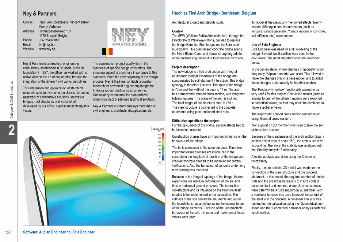
124
2
Cate
gory
2: C
ivil S
truct
ures
Ney & PartnersContact Thijs Van Roosbroeck, Vincent Dister,
Kenny VerbeeckAddress Terhulpsesteenweg 181 1170 Brussel, BelgiumPhone +32 26432180Email [email protected] www.ney.be
Harchies Tied Arch Bridge - Bernissart, Belgium
Architectural project and stability study.
ContextThe SPW (Walloon Public Administration), through the Directorate of Waterways Mons, decided to replace the bridge Harchies-Stambruges on the Bernissart municipality. This prestressed concrete bridge spans the Nimy-Blaton Canal and shows strong degradation of the prestressing cables due to excessive corrosion.
Project descriptionThe new bridge is a tied arch bridge with integral abutments: thermal expansions of the bridge are compensated by soil-abutment interaction. This bridge typology is therefore jointless. The span of the bridge is 70 m and the width of the deck is 14 m. The arch has a trapezoidal shaped cross section, with integrated lighting features. The plane of the arch is inclined.The total weight of the structural steel is 250 t.The steel structure is connected to the concrete abutments using post-tensioned steel rods.
Difficulties specific to the projectFor the calculation of the bridge, several effects had to be taken into account.
Construction phases have an important influence on the behaviour of the bridge.
The tie is connected to the concrete deck. Therefore, important tensile stresses are introduced in the concrete in the longitudinal direction of the bridge, and cracked concrete needed to be modelled for certain verifications. Also the behaviour of concrete under long term loading was modelled.
Because of the integral typology of the bridge, thermal expansions will result in deformation of the soil and thus in horizontal ground pressure. The interaction soil-structure and its influence on the structure itself, needed to be implemented in the calculation. The stiffness of the soil behind the abutments and under the foundations has an influence on the internal forces of the bridge elements. Because of the unpredictable behaviour of the soil, minimum and maximum stiffness values were used.
To model all the previously mentioned effects, twenty models differing in certain parameters (such as temporary stage geometry, Young’s module of concrete, soil stiffness, etc.) were needed.
Use of Scia EngineerScia Engineer was used for a 3D modelling of the bridge. Several functionalities were used in the calculation. The most important ones are described below.
In the design stage, where changes of geometry occur frequently, ‘Allplan roundtrip’ was used. This allowed to make the changes only in a base model, and to adapt these changes automatically in the other models.
The ‘Productivity toolbox’ functionality proved to be very useful for this project. Calculation results (such as internal forces) of the different models were exported in numerical values, so that they could be combined to make a global envelop.
The trapezoidal shaped cross section was modelled using ’General cross-section’.
‘Soil support on 2D member’ was used to take the soil stiffness into account.
Because of the slenderness of the arch section (span / section height ratio of about 150), the arch is sensitive to buckling. Therefore, the stability was analyzed with the ‘Stability analysis’ functionality.
A modal analysis was done using the ‘Dynamics’ functionality.
Finally, a more detailed 3D model was made for the connection of the steel structure and the concrete abutment. In this model, the required number of tension rods and the prestress necessary to insure contact between steel and concrete under all circumstances were determined. A ‘Soil support on 2D member’ with a nonlinear function was used to model the contact of the steel with the concrete. A nonlinear analysis was needed for the calculation using the ‘Geometrical non-linear’ and the ‘Geometrical nonlinear analysis surfaces’ functionalities.
Ney & Partners is a structural engineering consultancy, established in Brussels. Since its foundation in 1997, the office has worked with an active view on the art of engineering through the integration of the different civil works disciplines.
This integration and optimization of structural elements aims to overcome the classic hierarchic assembly of constructive solutions. Innovative bridges, roof structures and works of art developed by our office, express most clearly this vision.
The construction project quality lies in the synthesis of specific design constraints. The structural aspect is of primary importance to this synthesis. From the very beginning of the design process, Ney & Partners conducts a constant research for advanced engineering integration. In doing so, our position as Engineering Consultancy overcomes the standardized dimensioning of predefined technical solutions.
Ney & Partners currently employs more than 45 civil engineers, architects, draughtsman, etc.
Software: Allplan Engineering, Scia Engineer
Ney & Partners . . . . . . . . . . . . . . . . . . . . . . . . . . . . . . . . . . . . . . Harchies Tied Arch Bridge - Bernissart, Belgium

125
Project information
Short project description
Nemetschek Engineering User Contest 2011 - Category 2: Civil Structures
Cate
gory
2: C
ivil S
truct
ures
2
The new Harchies bridge, spanning 70 m, replaces the existing prestressed concrete bridge on the Nimy-Blaton Canal. The replacement is required because of the corroded strands of the latter.The new structure is a bowstring bridge with integral abutments: the thermal expansions are compensated by soil-abutment interaction. This bridge typology is therefore jointless. The arch has a trapezoidal shaped cross section, with integrated lighting features.
Owner SPWArchitect Ney & PartnersEngineering Office Ney & PartnersConstruction Period From 2011 to 2012Location Bernissart, Belgium
Harchies Tied Arch BridgeBernissart, Belgium
Ney & Partners . . . . . . . . . . . . . . . . . . . . . . . . . . . . . . . . . . . . . . Harchies Tied Arch Bridge - Bernissart, Belgium
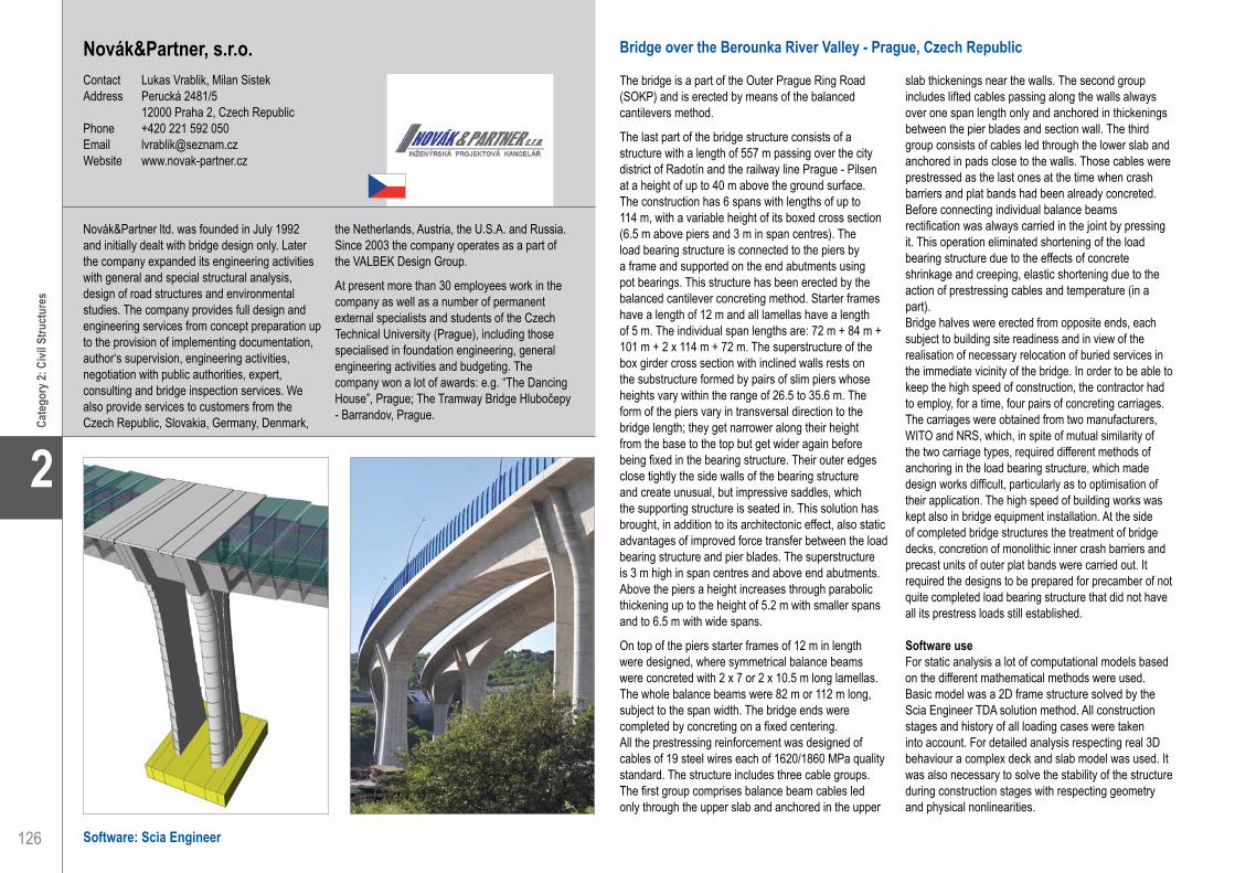
126
2
Cate
gory
2: C
ivil S
truct
ures
Novák&Partner, s.r.o.Contact Lukas Vrablik, Milan SistekAddress Perucká 2481/5 12000 Praha 2, Czech RepublicPhone +420 221 592 050Email [email protected] www.novak-partner.cz
Bridge over the Berounka River Valley - Prague, Czech Republic
The bridge is a part of the Outer Prague Ring Road (SOKP) and is erected by means of the balanced cantilevers method.
The last part of the bridge structure consists of a structure with a length of 557 m passing over the city district of Radotín and the railway line Prague - Pilsen at a height of up to 40 m above the ground surface. The construction has 6 spans with lengths of up to 114 m, with a variable height of its boxed cross section (6.5 m above piers and 3 m in span centres). The load bearing structure is connected to the piers by a frame and supported on the end abutments using pot bearings. This structure has been erected by the balanced cantilever concreting method. Starter frames have a length of 12 m and all lamellas have a length of 5 m. The individual span lengths are: 72 m + 84 m + 101 m + 2 x 114 m + 72 m. The superstructure of the box girder cross section with inclined walls rests on the substructure formed by pairs of slim piers whose heights vary within the range of 26.5 to 35.6 m. The form of the piers vary in transversal direction to the bridge length; they get narrower along their height from the base to the top but get wider again before being fixed in the bearing structure. Their outer edges close tightly the side walls of the bearing structure and create unusual, but impressive saddles, which the supporting structure is seated in. This solution has brought, in addition to its architectonic effect, also static advantages of improved force transfer between the load bearing structure and pier blades. The superstructure is 3 m high in span centres and above end abutments. Above the piers a height increases through parabolic thickening up to the height of 5.2 m with smaller spans and to 6.5 m with wide spans.
On top of the piers starter frames of 12 m in length were designed, where symmetrical balance beams were concreted with 2 x 7 or 2 x 10.5 m long lamellas. The whole balance beams were 82 m or 112 m long, subject to the span width. The bridge ends were completed by concreting on a fixed centering.All the prestressing reinforcement was designed of cables of 19 steel wires each of 1620/1860 MPa quality standard. The structure includes three cable groups. The first group comprises balance beam cables led only through the upper slab and anchored in the upper
slab thickenings near the walls. The second group includes lifted cables passing along the walls always over one span length only and anchored in thickenings between the pier blades and section wall. The third group consists of cables led through the lower slab and anchored in pads close to the walls. Those cables were prestressed as the last ones at the time when crash barriers and plat bands had been already concreted.Before connecting individual balance beams rectification was always carried in the joint by pressing it. This operation eliminated shortening of the load bearing structure due to the effects of concrete shrinkage and creeping, elastic shortening due to the action of prestressing cables and temperature (in a part). Bridge halves were erected from opposite ends, each subject to building site readiness and in view of the realisation of necessary relocation of buried services in the immediate vicinity of the bridge. In order to be able to keep the high speed of construction, the contractor had to employ, for a time, four pairs of concreting carriages. The carriages were obtained from two manufacturers, WITO and NRS, which, in spite of mutual similarity of the two carriage types, required different methods of anchoring in the load bearing structure, which made design works difficult, particularly as to optimisation of their application. The high speed of building works was kept also in bridge equipment installation. At the side of completed bridge structures the treatment of bridge decks, concretion of monolithic inner crash barriers and precast units of outer plat bands were carried out. It required the designs to be prepared for precamber of not quite completed load bearing structure that did not have all its prestress loads still established.
Software useFor static analysis a lot of computational models based on the different mathematical methods were used. Basic model was a 2D frame structure solved by the Scia Engineer TDA solution method. All construction stages and history of all loading cases were taken into account. For detailed analysis respecting real 3D behaviour a complex deck and slab model was used. It was also necessary to solve the stability of the structure during construction stages with respecting geometry and physical nonlinearities.
Novák&Partner ltd. was founded in July 1992 and initially dealt with bridge design only. Later the company expanded its engineering activities with general and special structural analysis, design of road structures and environmental studies. The company provides full design and engineering services from concept preparation up to the provision of implementing documentation, author‘s supervision, engineering activities, negotiation with public authorities, expert, consulting and bridge inspection services. We also provide services to customers from the Czech Republic, Slovakia, Germany, Denmark,
the Netherlands, Austria, the U.S.A. and Russia. Since 2003 the company operates as a part of the VALBEK Design Group.
At present more than 30 employees work in the company as well as a number of permanent external specialists and students of the Czech Technical University (Prague), including those specialised in foundation engineering, general engineering activities and budgeting. The company won a lot of awards: e.g. “The Dancing House”, Prague; The Tramway Bridge Hlubočepy - Barrandov, Prague.
Software: Scia Engineer
Novák&Partner, s.r.o.. . . . . . . . . . . . . . . . . . . . . . . . . . . . . . . . . . Bridge over the Berounka River Valley - Prague, Czech Republic

127
Project information
Short project description
Nemetschek Engineering User Contest 2011 - Category 2: Civil Structures
Cate
gory
2: C
ivil S
truct
ures
2
Owner The Road and Motorway Directorate, Czech RepublicArchitect Patrik Kotas, Petr ŠafránekGeneral Contractor Bögl&KrýslEngineering Office Novák&Partner, s.r.o.Construction Period From March 2008 to September 2010Location Prague, Czech Republic
The bridge structures lead the motorway ring over the Berounka River valley and the adjacent inundation area with roads, railway sidings and a railway line. The last part of the bridge complex is a structure with a length of 557 m, passing the valley at a height of up to 40 m above the ground surface. The structure has 6 spans with lengths up to 114 m with a variable height of its boxed cross section.
Bridge over the Berounka River ValleyPrague, Czech Republic
Novák&Partner, s.r.o.. . . . . . . . . . . . . . . . . . . . . . . . . . . . . . . . . . Bridge over the Berounka River Valley - Prague, Czech Republic

128
2
Cate
gory
2: C
ivil S
truct
ures
Spoorkruising Riekerpolder - Amsterdam, Nederland
OntwerpNa de aanbiedingsfase is het Project OV SAAL Zuidtak West gegund aan de Combinatie Nieuwe Meer Sporen V.O.F. (CNMS, bestaande uit Van Hattum en Blankevoort B.V. en VolkerRail Nederland B.V.) Voor de realisatie van het Project OV SAAL Zuidtak West is een Alliantieovereenkomst (Amsterdamse WALTZ) gesloten tussen ProRail (Opdrachtgever) en de Combinatie Nieuwe Meer Sporen V.O.F. (Opdrachtnemer en tevens Uitvoerend Aannemer).
Het ontwerp voor dit project betreft een multidisciplinair ontwerp, waarbij civiele constructies, bovenleiding, beveiliging, spoor en seinen en het gefaseerd ontwerpen van de constructies onder system engineering wordt uitgewerkt. Het spoor kruist hierbij ongelijkvloers o.a. rijkswegen, stadswegen, waterwegen en het spoor zelf.
Het multidisiplinaire ontwerp (civiel ontwerp, bovenleiding, beveiliging, spoor en seinen) wordt uitgevoerd door RailinfraSolutions en door het ontwerpbureau VolkerInfra Design van Van Hattum en Blankevoort.
Het project OV SAAL Zuidtak WestOV SAAL Zuidtak West bevat de spooruitbreiding vanaf Riekerpolder aansluiting tot aan het station Amsterdam Zuid WTC. Op dit traject worden gerealiseerd: spoorviaducten (fly-over Riekerpolder, kruising verbindingsweg A4-A10, kruising Schinkel (beweegbare brug), kruising Museumtramlijn, kruising Amstelveensweg), diverse keerwandconstructies en aanpassing en sloop van bestaande spoorviaducten.
Multidisciplinair projectHet multidisciplinaire karakter levert veel, zowel interne als externe, raakvlakken. Voor het ontwerp van de fly-over bij Riekerpolder, één van de kunstwerken met de meeste raakvlakken en raakvlakeisen, is besloten om de draagconstructie in 3D te ontwerpen met Allplan. De fly-over wordt gerealiseerd op een locatie waar verschillende (spoor-)wegen elkaar kruisen. Ter plaatse van Riekerpolder wordt een aantal kunstwerken (gedeeltelijk) gesloopt om de nieuwe infrastructuur mogelijk te maken. Hierbij is de fasering erg belangrijk, omdat de doorstroming van het bestaande verkeer
zo min mogelijk hinder mag ondervinden van de uitvoeringswerkzaamheden. Het voordeel van 3D Allplan is dat uitvoeringsconflicten tijdens het ontwerp beter gesignaleerd kunnen worden. Tevens kan het ontwerp met bijbehorende raakvlakken beter gevisualiseerd worden, dan vanaf platte tekeningen. Dit geldt zowel voor interne raakvlakken als voor externe raakvlakken, zoals die met de omgeving.
Kunstwerk KW04C fly-over RiekerpolderEén van de kunstwerken is de fly-over bij Riekerpolder, waarbij een enkel spoor vanaf Schiphol afbuigt naar Sloterdijk en verschillende sporen en rijksweg A4 kruist. Het kunstwerk begint ten westen van de Johan Huizingalaan. Middels een kistdam wint het spoor van de fly-over hoogte, zodat het spoor voorbij de Johan Huizingalaan het naastgelegen spoor kan kruisen. Vanaf de Johan Huizingalaan gaat de kistdam over in een fly-over met overspanningen variërend van 26 tot 41 m.
Op dit moment wordt de variantenstudie uitgevoerd. Om goed inzicht te krijgen of overal voldaan wordt aan het profiel van vrije ruimte, wordt de fly-over geheel in 3D uitgewerkt met Allplan. Hierbij wordt naast het genoemde profiel van vrije ruimte onderzocht wat de beste locaties voor de ondersteuningen zijn in relatie met de technisch en economisch haalbare overspanningen van het spoordek en de zichtlijnen van het onderliggende spoor. Het plaatsen van pijlers beperkt namelijk het zicht van het onderliggende spoor, waardoor seinen niet goed zichtbaar kunnen zijn. Dit kan gevaarlijke situaties opleveren. Daarnaast wordt rekening gehouden met funderingen van bestaande kunstwerken, zoals die van de viaducten van de A4.
Door het toepassen van Allplan kunnen in vervolgfasen van het project hoeveelheden snel en eenvoudig verkregen worden voor de werkvoorbereider en de kostendeskundige. Voor de uitvoering geldt, dat het 3D-model omgezet kan worden naar vorm- en wapeningstekeningen. Bij het uitwerken van de wapening in 3D kunnen eventuele conflictpunten eerder zichtbaar gemaakt worden. Verder wordt onderzocht in hoeverre de uitvoeringsplanning gekoppeld kan worden aan het 3D-model, zodat de fasering van de uitvoering duidelijker naar voren kan komen.
Railinfra SolutionsOnder deze naam hebben advies- en ingenieursbureaus Royal Haskoning en Witteveen+Bos en het Duitse DB International de handen ineen geslagen. Op basis van nationale en internationale gebundelde kennis en expertise biedt de organisatie integrale oplossingen op het terrein van railinfrastructuur. Zo richt Railinfra Solutions zich op het aanpassen van bestaande spoor- en tramlijnen, het vernieuwen van bovenleidingen, het ontwerpen van nieuwe railverbindingen en het ontwikkelen van (nieuwe) stations en emplacementen. Met een vierde
partij, Verebus Engineering, is een exclusief samenwerkingsverband gesloten voor de discipline treinbeveiliging. Railinfra Solutions is volledig erkend door ProRail. De deskundigheid van Witteveen+Bos en Royal Haskoning op het gebied van ruimtelijke ontwikkeling, stedenbouw en milieubeleid stelt Railinfra Solutions in staat ‘die omgeving’ in ieder spoorproject en in ieder advies mee te nemen. Bovendien brengt DB International ruime expertise met zich mee voor bijvoorbeeld ontwikkelingen als ERTMS en 25kV bovenleidingspanning.
Royal HaskoningContact Kees van IJselmuijdenAddress Entrada 301 1096 ED Amsterdam, The NetherlandsPhone +31 205697700Email [email protected] www.royalhaskoning.com
Software: Allplan Engineering
Royal Haskoning . . . . . . . . . . . . . . . . . . . . . . . . . . . . . . . . . . . . . Fly-Over Riekerpolder - Amsterdam, The Netherlands

129
Project information
Short project description
Nemetschek Engineering User Contest 2011 - Category 2: Civil Structures
Cate
gory
2: C
ivil S
truct
ures
2
This project is about the multidisciplinary railway extension activities in Amsterdam. More specifically the fly-over at the Riekerpolder, where a single track from Schiphol Airport branches off to Sloterdijk and where various tracks cross the A4. Since the fly-over has to be achieved at a location where a lot of infrastructure intersects (highway, railway, urban traffic), it was decided to use Allplan for the complex 3D design of this work of art. One of the advantages of 3D Allplan was that execution conflicts could already be identified during the design.
Owner ProRailGeneral Contractor Van Hattum en BlankenvoortEngineering Office Railinfra SolutionsConstruction Period From September 2010 to January 2016Location Amsterdam, The Netherlands
Fly-Over RiekerpolderAmsterdam, The Netherlands
Royal Haskoning . . . . . . . . . . . . . . . . . . . . . . . . . . . . . . . . . . . . . Fly-Over Riekerpolder - Amsterdam, The Netherlands

130
2
Cate
gory
2: C
ivil S
truct
ures
Software: Scia Engineer
Boogbrug - Grobbendonk, België
NV De Scheepvaart heeft opdracht gegeven voor de bouw van een nieuwe boogbrug te Grobbendonk. Dit ter vervanging van een reeds bestaande brug. De nieuwe constructie wordt gebouwd op het industrieterrein Beverdonk. De stalen boogbrug overspant 108 m. Twee kokervormige bogen hellen hierbij naar mekaar toe. Het dek (stalen profielen + betonnen brugdek) hangt op m.b.v. stalen hangers aan de boog en is op de uiteinden verbonden met boog m.b.v. de einddwarsdragers. De afwerking van de brug is voorzien voor juni 2011.
GeometrieHet lengteprofiel van het brugdek verloopt parabolisch volgens een straal van 1.620 m. Deze kromming wordt in meegenomen in het berekeningsmodel van de brug.Karakteristieken van de brug:• Naam: Brug C0499 te Grobbendonk• Gewicht: +/-560 ton staal, +/-760 ton beton (= dek)• Lengte: 108 m (as op as opleggingen)• Breedte: 14.9 m• Pijl-boog: 17 m (afstand as boog - as hoofdligger in
het midden van de brug)• Gedeelte wegverkeer brug: 2 rijrichtingen - 1 rijstrook
per rijrichting, breedte per rijrichting = 3 m• Gedeelte fiets-voetgangerszone, brug: 2 rijrichtingen
- 1 strook per rijrichting, breedte strook = 2 m
StabiliteitDe bogen zijn met elkaar verbonden d.m.v drie windverbanden. Er zijn geen extra kruisverbanden aangebracht tussen de windverbanden om het aanzicht van de brug rustig te houden. De bogen komen in het midden naar mekaar toe en vormen samen met de windverbanden één geheel.
Uitdagingen in de berekening:• Uit de resultaten van de stabiliteitsberekeningen
volgt dat 2e orde effecten dienen beschouwd te worden. Dit is enkel mogelijk door het uitvoeren van niet-lineaire berekeningen, waarbij men de optie 2e orde - geometrische niet-lineariteit dient aan te vinken.
• Een optimaal ontwerp wordt geëist. Hiervoor is de ontwerper genoodzaakt om imperfecties in te voeren en 2e orde te gaan rekenen, waardoor
de stabiliteitscontrole zich herleidt tot een spanningscontrole, welke doorgaans gunstigere resultaten oplevert dan conservatieve knikcontroles m.b.v. knikcurves.
• Omdat men 2e orde berekeningen dient te maken, is het noodzakelijk om alle belastingsgevallen in 1 rekenmodel te hebben. Hiervoor dient men het belastingsgeval “eigengewicht staal” te simuleren met behulp van temperatuurslasten (zowel uniforme temperaturen als temperatuursgradiënten) om rekening te kunnen houden met de wijze van monteren en zo de correcte spanningstoestand te bekomen onder het eigengewicht van het staal.
Aanpak voor de berekening van deze uitdagingenMet behulp van temperatuurslasten en puntkrachten worden combinaties aangemaakt in het totaalmodel die dezelfde momentelijnen en normaalkrachten geven als deze die ontstaan uit de superpositie van de 3 montagefases.Deze temperatuursbelastingen bestaan uit• Bij de hangers: uniforme temperaturen• Bij de boogdelen: temperatuursgradiënten
De waarden van deze temperatuurslasten worden bepaald aan de hand van een stelsel van lineaire vergelijkingen waarvan de coëfficiënten gegeven worden door de snedekrachten van de afzonderlijke belastingsgevallen die in voorgaande zijn weergegeven. Daarnaast dienen ook imperfecties ingevoerd te worden. Als imperfectie voor de globale analyse wordt de elastische knikvorm opgelegd. De amplitude van deze imperfectie wordt bepaald met behulp van § 5.2.4.3 van ENV 1993-2. Elastische knikkrommes worden bepaald met behulp van stabiliteitscombinaties waarbij verschillende posities van de mobiele verkeersbelasting worden beschouwd. Deze posities worden bepaald voor de 6 meest belaste boogsecties. Daarnaast worden deze nadelige verkeersposities gecombineerd met wind OW en wind WO.
SBE nv. . . . . . . . . . . . . . . . . . . . . . . . . . . . . . . . . . . . . . . . . . . . . Bow Bridge - Grobbendonk, Belgium
SBE nv is een vitaal en dynamisch studie-, teken- en ingenieursbureau, gevestigd te Sint-Niklaas nabij de Antwerpse haven.
Het bureau heeft zich gedurende de laatste 30 jaar geprofileerd als een studie- en adviesbureau gespecialiseerd in havenconstructies, burgerlijk bouwkunde, geotechnische problemen, staalstructuren en funderingstechnieken
Met meer dan 30 jaar ervaring in de verschillende domeinen van de bouwkunde, en vooral dan op het gebied van grote infrastructurele projecten,
zijn de projectingenieurs de leidende kracht voor een jong en dynamisch team dat met een grote gedrevenheid de meest uiteenlopende opdrachten aanpakt.
De studieopdrachten worden uitgewerkt met de nadruk op kwaliteit en uitvoerbaarheid, doch steeds rekening houdend met de financiële en economische haalbaarheid, met referenties in Europa, Oekraïne, Korea, Nigeria, Panama, etc.
SBE nvContact Sven Barrez, Guy Van Nuffel, Wim De Nutte,
Lucrèse VermaereAddress Slachthuisstraat 71 9100 Sint-Niklaas, BelgiumPhone +32 3 777 95 19Email [email protected] www.sbe.be

131
Project information
Short project description
Nemetschek Engineering User Contest 2011 - Category 2: Civil Structures
Cate
gory
2: C
ivil S
truct
ures
2
Owner Dienst voor de ScheepvaartArchitect AMSGeneral Contractor Victor Buyck Steel ConstructionEngineering Office SBE nvConstruction Period From August 2010 to June 2011Location Grobbendonk, Belgium
NV De Scheepvaart wanted to replace the old bridge across the Albert canal. The new bridge has a single span of 108 m and a steel weight of 560 t. The arches (box beams) are transversally connected with each other at three places. The bridge concrete deck is hung up at the arches by vertically placed hangers (D100). The upper structure is studied in an overall Scia Engineer model, including the influences of the construction phases. In this model, we used the Scia Engineer modules: Stability calculations, Non-linear calculations, including second order effects and global and local imperfections, and Profile check according to EC3.
Arch BridgeGrobbendonk, Belgium
SBE nv. . . . . . . . . . . . . . . . . . . . . . . . . . . . . . . . . . . . . . . . . . . . . Bow Bridge - Grobbendonk, Belgium

132
2
Cate
gory
2: C
ivil S
truct
ures
Brug met Drie Overspanningen ‘Westelijke Tangent’ - Sint-Niklaas, België
AlgemeenIn het kader van de ringsluiting rond Sint-Niklaas is in het project “Westelijke Tangent” een wegbrug voorzien over de spoorweg. De brug is van het gemengde type en heeft drie overspanningen. Het dek is uitgevoerd in beton dat met deuvels verbonden is met een onderliggende 3D-vakwerkstructuur. De brug ligt in een bocht van het tracé.
GeometrieDe brug is opgesplitst over de breedte in twee onafhankelijke delen, elk bestaande uit 5 onderregels en 6 bovenregels die samen met de betonnen brugdekplaat en met de diagonalen en de stijlen een driedimensionale vakwerkstructuur vormen.
De brug is zowel in grondvlak als in verticaal vlak gebogen. Het bovenvlak van de brug ligt gebogen volgens een parabool. Tevens is de verkanting van 5% ingerekend voor het ondervlak.
Het bovenvlak is samengesteld uit een betonplaat, die door deuvels verbonden is met een stalen I-profiel, dat op zijn beurt voor de eenvoud van de montage
is samengesteld uit 2 gekoppelde U-profielen. In de stortfase van de brugdekplaat wordt de stabiliteit in het bovenvlak gewaarborgd door de aanwezige windverbanden. Deze windverbanden blijven bewaard na de verharding van de brugdekplaat.
De boven- en onderregels liggen geschrankt in aanzicht zodat voor elke onderregel er twee bovenliggende bovenregels zijn. De diagonalen en stijlen zijn stalen buisprofielen en lopen schuin tussen de boven- en onderregel. Zij verzorgen mede de stabiliteit in dwarse zin van de brug en verhinderen het wegslaan van de onderregel.
De onderregels zijn gevormd uit een buisprofiel, dat zowel in het horizontaal als in het verticaal vlak gebogen is.
Gemiddelde overspanning van een hoofdligger tussen de pijlers: 22.1 mGemiddelde afstand van de pijlers naar het landhoofd aan de korte zijde: 12.1 mGemiddelde afstand van de pijlers naar het landhoofd aan de langse zijde: 18.25 m
StabiliteitDe 3D-vakwerkstructuur en het betondek werken samen als een groot geheel. Het betondek doet hierbij dienst als bovenregel. De deuvels op de stalen hoofdliggers bovenaan in de stalen 3D-structuur zorgen voor de samenwerking van het geheel. In het model zijn deze deuvels eveneens gesimuleerd.
De pijlers zijn pendelend en scharnierend verbonden met de bovenbouw en de fundering.
ModelleringselementenDe brug is in een bocht gelegen. In het grondvlak neemt de brug deze bocht over. Door de vorm en de vrije ruimte die door het spoor gereserveerd dient te worden, is ook in verticaal vlak de brug gebogen. Dit maakt dat de stalen hoofdbogen, die als onderregel dienst doen, in de twee vlakken gebogen zijn. In het model zijn deze als splines ingevoerd om met deze vorm rekening te kunnen houden in de krachtswerking.
Software: Scia Engineer
SBE nv. . . . . . . . . . . . . . . . . . . . . . . . . . . . . . . . . . . . . . . . . . . . . Bridge Structure with Three Spans ‘West Tangent’ - Sint-Niklaas, Belgium
SBE nv is een vitaal en dynamisch studie-, teken- en ingenieursbureau, gevestigd te Sint-Niklaas nabij de Antwerpse haven.
Het bureau heeft zich gedurende de laatste 30 jaar geprofileerd als een studie- en adviesbureau gespecialiseerd in havenconstructies, burgerlijk bouwkunde, geotechnische problemen, staalstructuren en funderingstechnieken
Met meer dan 30 jaar ervaring in de verschillende domeinen van de bouwkunde, en vooral dan op het gebied van grote infrastructurele projecten,
zijn de projectingenieurs de leidende kracht voor een jong en dynamisch team dat met een grote gedrevenheid de meest uiteenlopende opdrachten aanpakt.
De studieopdrachten worden uitgewerkt met de nadruk op kwaliteit en uitvoerbaarheid, doch steeds rekening houdend met de financiële en economische haalbaarheid, met referenties in Europa, Oekraïne, Korea, Nigeria, Panama, etc.
SBE nvContact Sven Barrez, Guy Van Nuffel, Wim De Nutte,
Lucrèse VermaereAddress Slachthuisstraat 71 9100 Sint-Niklaas, BelgiumPhone +32 3 777 95 19Email [email protected] www.sbe.be
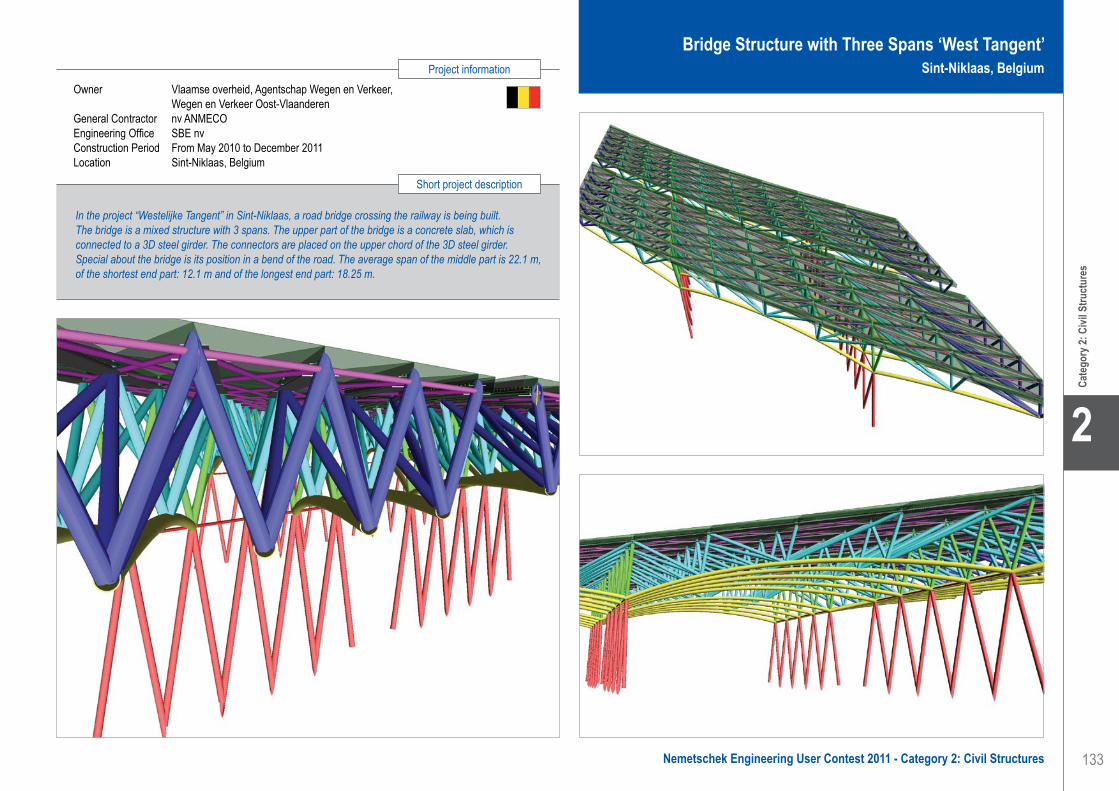
133
Project information
Short project description
Nemetschek Engineering User Contest 2011 - Category 2: Civil Structures
Cate
gory
2: C
ivil S
truct
ures
2
Owner Vlaamse overheid, Agentschap Wegen en Verkeer, Wegen en Verkeer Oost-VlaanderenGeneral Contractor nv ANMECOEngineering Office SBE nvConstruction Period From May 2010 to December 2011Location Sint-Niklaas, Belgium
In the project “Westelijke Tangent” in Sint-Niklaas, a road bridge crossing the railway is being built. The bridge is a mixed structure with 3 spans. The upper part of the bridge is a concrete slab, which is connected to a 3D steel girder. The connectors are placed on the upper chord of the 3D steel girder. Special about the bridge is its position in a bend of the road. The average span of the middle part is 22.1 m, of the shortest end part: 12.1 m and of the longest end part: 18.25 m.
Bridge Structure with Three Spans ‘West Tangent’ Sint-Niklaas, Belgium
SBE nv. . . . . . . . . . . . . . . . . . . . . . . . . . . . . . . . . . . . . . . . . . . . . Bridge Structure with Three Spans ‘West Tangent’ - Sint-Niklaas, Belgium

134
2
Cate
gory
2: C
ivil S
truct
ures
Passerelle en Aluminium Ravel - Autres-Eglise, Belgique
IntroductionC’est en 1995 que le projet Ravel a officiellement vu le jour. Il est né de la volonté de développer une politique de mobilité efficace et respectueuse de l’environnement. La Région Wallonne a ainsi décidé d’aménager un réseau au profit du trafic non motorisé. Aujourd’hui, le Ravel compte plus d’un millier de kilomètres de voies aménagées…
Depuis l’inauguration de la première ligne en 1996, le Ravel n’a cessé de grandir. Dans le cadre des travaux de la ligne 147, le tracé immerge le promeneur dans une des plus belles régions agricoles de Belgique, dont l’opulence fait alterner champs de blé et de betteraves, la société NSEI, qui a conçu et fabriqué la passerelle, nous a confié la mission d’études et de réalisation des plans d’une passerelle pour piétons et cyclistes.
Le cahier des charges imposait que cette passerelle soit entièrement réalisée en aluminium. Pour facilités de montage, la société NSEI souhaitait fabriquer la passerelle en une seule pièce entièrement soudée.
Données techniques • Portée : 12.00 m• Largeur : 3.00 m• Hauteur : 2.00 m• Structure entièrement soudée en atelier• Matériaux : différents alliages d’aluminium : EN-AW
6060-T6, EN-AW 5083-H111
Charges admissibles• Neige, vent et sollicitations thermiques suivant normes• Surcharge d’utilisation de 5.00 kN/m²• Poussée horizontale sur garde corps de 1.00 kN/m• Sollicitation accidentelle : Véhicule de 12.00 t avec
accélération et freinage correspondant.
Processus de calculLa structure aluminium a été étudiée en plusieurs phases : 1. La structure primaire a été étudiée à l’aide d’un
modèle 3D de type barres. L’aluminium a la particularité d’avoir des propriétés mécaniques fortement influencées par la présence de soudures, la résistance peut être réduite de plus de la moitié pour certains alliages, cet affaiblissement se produit dans les Zones Affectées Thermiquement (ZAT) par les soudures. L’utilisation du module Aluminium a permis d’optimiser la structure et de vérifier l’influence des soudures sur la résistance locale des barres. Le module Dynamique a été utilisé pour la détermination des premiers modes propres de la structure.
2. Le platelage a été étudié à l’aide d’un modèle 3D de type plaques. Le module Plaques a permis dans un premier temps de dimensionner le platelage en vérifiant les contraintes et déformations, de dimensionner les soudures entre la tôle supérieure du platelage et les différents raidisseurs
3. La structure a ensuite été vérifiée dans son entièreté en tenant compte de la présence du platelage et de son effet diaphragme.
L’utilisation du logiciel Scia Engineer pour ce projet a donc permis de dimensionner et d’optimiser la structure en aluminium de cette passerelle et tenant compte de l’influence des soudures sur la résistance des barres et tôles.
Software: Scia Engineer
Steel EngineeringContact Olivier DebusschereAddress Comognes de Temploux, 2 5020 Temploux, BelgiumPhone +32 496 53 20 54Email [email protected]
Créé en 2005, Steel Engineering est un bureau d’études qui se distingue par son savoir-faire et ses compétences dans le calcul et la réalisation de plans de structures métalliques (acier, inox et aluminium).
Nos missions en structures métalliques • Etudes d’exécution pour bureaux d’ingénieries
ou sociétés de charpentes métalliques• Etudes de faisabilité• Conception et design• Conseils et expertises techniques
Types d’études réaliséesDimensionnement et optimisation de structures, vérification de structures existantes, études au feu, sismiques, en fatigue…
Types de structures étudiées Charpentes industrielles, passerelles, ponts roulants, rayonnages, échafaudages, pylônes…
Avec des outils informatiques performants, Steel Engineering offre à ses clients un service moderne, innovant et d’excellente qualité.
Steel Engineering . . . . . . . . . . . . . . . . . . . . . . . . . . . . . . . . . . . . Aluminium Footbridge Ravel - Autre-Eglise, Belgium

135
Project information
Short project description
Nemetschek Engineering User Contest 2011 - Category 2: Civil Structures
Cate
gory
2: C
ivil S
truct
ures
2
Owner Service Public de WallonieArchitect SPWGeneral Contractor NSEIEngineering Office Steel EngineeringConstruction Period 2010Location Autre-Eglise, Belgium
This project is about an aluminium bridge for pedestrians and bike-riders; it is a part of the Ravel Network, 1.200 km of tracks in the South of Belgium. The company NSEI, that designed and manufactured the footbridge, entrusted Steel Engineering the mission to take care of the studies and realization of the plans of this bridge. This footbridge had to be entirely made out of aluminium and manufactured in only one entirely welded part. The aluminium design functionalities of Scia Engineer helped a lot to analyse the structure in details and optimize it including influence of welds.
Aluminium Footbridge RavelAutre-Eglise, Belgium
Steel Engineering . . . . . . . . . . . . . . . . . . . . . . . . . . . . . . . . . . . . Aluminium Footbridge Ravel - Autre-Eglise, Belgium

136
2
Cate
gory
2: C
ivil S
truct
ures
Bridges ‘Oude dokken’ - Ghent, Belgium
This site used to be the harbour of Ghent. Over time the activities of the harbour moved north and the industrial site was left without much life.
This project ground will become the new home for many ‘Gentenaars’. But also due to the good (public) mobility and access points there will be new offices, places for recreation, culture and parks.
All functions for a new city part of Ghent.
Project descriptionThe old docks separate the site into two areas, west and east. Three bridges, reserved for pedestrians and bicycles, connect the quays of the channel and form the link between the two parts. The bridges seem, as horizontal pontoons, even breakwaters of the docks.
The main question was how to make of these bridges ‘landmarks’ in this new developed site.
The constraints in terms of slopes for disabled persons and vertical clearance for waterway traffic brought the solution for a movable bridge.
The movement of the bridges is a symbolic reference to the dynamic urban evolution of the site. Using long slopes makes it possible to have access to the bridge at all times.
The slope starts at quay level and will only rise for waterway traffic. The slope depends on the passing ship: the bridge only rises as high as needed for passage.
Design approachAll three bridges have the same approach, even with their difference in length. The longer bridges are 110 m long and have a width of 6 m.
The long bridges consist of two bridge parts, a moveable and a fixed part, while the shorter bridge only consists of the moveable part.
The first part exists of three bridge decks. The smaller middle part is the table that lifts to let waterway traffic pass. Both larger adjacent decks are connected to the table with hinges and roll on a set of wheels on the quay wall and on the fixed part of the bridge.
The second bridge part also consists of three bridge parts, equal in size and shape, but all fixed together.
The structure of the bridge is formed by a steel caisson variable in height, with the highest section in the middle of the span. This head caisson lays perpendicular to the supports of the bridge. Viewed sideways, it forms a triangle. Together with smaller transverse beams, also variable in height, and longitudinal beams with continuous section, they form the framework on which lays the wooden bridge deck.
The lifting table has vertical supports at both ends of the central girder. The deck is fixed on top of these two piles, which contain the electro mechanic jacks.
The piles under the lifting table each roll between two sets of wheels which take on the horizontal forces, so the jack only takes on a vertical force.
The vertical supports of the fixed bridge part are also on the central girder. These piles are fixed in the ground unlike the piles of the lifting table which have a housing of larger circular tubes.
A system of rails and sliding plates guarantees a safe passage for pedestrians and bicycles.
Design with Scia EngineerThe design of the bridge was split into two models: one where the bridge is open and one where the bridge is closed for waterway traffic. Other Scia Engineer models were used to calculate ground parameters and details.
Scia Engineer made it possible to insert the project as how it would be in reality, with variable sections, all fixed details and with the existing ground parameters. Internal forces and reactions obtained from Scia Engineer were used to calculate the connections (steel connections and electromechanical parts).
In this project the deformation, the forces on details, temperature differences and a dynamic design were the most essential determining factors.
With this calculation the demands of the architect could be met, respecting all determining factors to keep the design of the structure as thin and elegant as possible.
Software: Scia Engineer
Technum-Tractebel Engineering . . . . . . . . . . . . . . . . . . . . . . . . . Bridges ‘Oude Dokken’ - Ghent, Belgium
Technum-Tractebel Engineering is a multi-disciplinary engineering and consultancy provider with international ambitions.
Our services include project management, studies, design and consultancy in: buildings, port & hydraulic engineering, transport infrastructure & urban development and strategic consultancy & analysis.
The combination of our strong position in Flanders and GDF SUEZ through our mother company, Tractebel Engineering provides international players with extraordinary support.
Efficiency and innovation are the keywords in our offer focused on providing you with a sustainable solution to your project.
Technum-Tractebel EngineeringContact Bart DesloovereAddress Kortrijksesteenweg 1144-a 9051 Sint Denijs Westrem, BelgiumPhone +32 92400911Email [email protected] www.technum-tractebel-engineering.be

137
Project information
Short project description
Nemetschek Engineering User Contest 2011 - Category 2: Civil Structures
Cate
gory
2: C
ivil S
truct
ures
2
Owner Waterwegen en Zeekanaal NVArchitect Feichtinger ArchitectesGeneral Contractor Herbosch KiereEngineering Office Technum-Tractebel EngineeringConstruction Period From March 2010 to ...Location Ghent, Belgium
The project is about three new moveable pedestrian and bicycle bridges across the ‘Oude Dokken’ in the old harbour of Ghent. The bridges are part of a larger project which combines living, shopping, schools and parks in this old industrial site. The bridges are moveable but remain accessible during the movement. This was made possible by the use of very long slopes. The bridges are wide, but are only supported by central columns. Scia Engineer was used for the calculation and dimensioning of the steelwork.
Bridges ‘Oude Dokken’Ghent, Belgium
Technum-Tractebel Engineering . . . . . . . . . . . . . . . . . . . . . . . . . Bridges ‘Oude Dokken’ - Ghent, Belgium

138
2
Cate
gory
2: C
ivil S
truct
ures
Technum-Tractebel Engineering . . . . . . . . . . . . . . . . . . . . . . . . . New lock at Ivoz Ramet - Flémalle, Belgium
Software: ESA-Prima Win, Scia Engineer
New lock at Ivoz Ramet - Flémalle, Belgium
BackgroundThe new lock at Ivoz Ramet (a municipality of Flémalle) on the Meuse River near Liège is part of the project to develop a network of trans-European inland waterways. The new lock is 225 m long and 25 m wide, allowing the passage of class VI b vessels.
The river traffic at this location increased by 83% in 20 years and reached 11.5 million tonnes in 2008. The largest tonnage in the entire Walloon Region passes through this hydraulic lock. The large lock, in addition to being run down, is not big enough to fulfil both current and future requirements. Thus, in 2004, the General Directorate for Mobility and Waterways began designing a new chamber measuring 225 m by 25 m. These dimensions are similar to those of the locks on the Albert Canal, which constitutes part of the downstream reach, to those of the Andenne and Grands-Malades locks built in the upstream during the last third of the 20th century, and to those of the future Lanaye lock. The lock lies on the Rhine/Meuse - Danube trans-European priority water transport corridor. The various studies conducted prior to the construction of the new
lock therefore benefited from financial aid from the European Union. In the field of river transport, this project, as well as those regarding the fourth Lanaye lock, the Seine-North and Seine-Escaut links, the Ampsin-Neuville lock and port development throughout the network, such as the Trilogiport project (Liege), are closely connected.
MissionTechnum-Tractebel Engineering and the Greisch consultancy were awarded the two contracts for studies (and execution follow-up) relating to civil engineering and electromechanical equipment for the completion of the new lock, including the incorporation of new equipment alongside the existing installation at the Ivoz Ramet locks. For each of the two contracts the mission consists of full studies of works and facilities as well as the establishment of contracts for works and completion follow-up. The studies also include a landscaping study designed to integrate the facilities into the environment as well as the installation of a hydroelectric production unit to meet the facility’s energy needs.
The works must be conducted in such a way that the existing facility can continue to operate during the construction, in particular the 136 x 16 m lock contiguous to the new lock, the dam and the associated hydroelectric power station.
Use of Scia Engineer and ESA-Prima WinThree models were elaborated for the three different gates: two traditional gates and one moveable floating gate. This floating gate can be used to inspect and maintain the other gates. The first two gates were modelled in ESA-Prima Win. The last one was modelled in Scia Engineer. Scia Engineer made it easier to model the different plates and to check the correct orientation and location of different stiffeners, Visualizations of results can be quite hard for complex plate models. Again Scia Engineer proved to be easier to use and more powerful.
Technum-Tractebel Engineering is a multi-disciplinary engineering and consultancy provider with international ambitions.
Our services include project management, studies, design and consultancy in: buildings, port & hydraulic engineering, transport infrastructure & urban development and strategic consultancy & analysis.
The combination of our strong position in Flanders and GDF SUEZ through our mother company, Tractebel Engineering provides international players with extraordinary support.
Efficiency and innovation are the keywords in our offer focused on providing you with a sustainable solution to your project.
Technum-Tractebel EngineeringContact Bart DesloovereAddress Kortrijksesteenweg 1144-a 9051 Sint Denijs Westrem, BelgiumPhone +32 92400911Email [email protected] www.technum-tractebel-engineering.be

139
Project information
Short project description
Nemetschek Engineering User Contest 2011 - Category 2: Civil Structures
Cate
gory
2: C
ivil S
truct
ures
2
New lock at Ivoz RametFlémalle, Belgium
Technum-Tractebel Engineering . . . . . . . . . . . . . . . . . . . . . . . . . New lock at Ivoz Ramet - Flémalle, Belgium
The new lock at Ivoz Ramet (a municipality of Flémalle) on the Meuse River near Liège is part of the project to develop a network of trans-European inland waterways. The new lock has a length of 225 m and a width of 25 m, allowing the passage of class VI b vessels. Scia Engineer (and ESA-Prima Win) was used for the design of the two types of lock gates and a floating moveable gate to close the lock for repair purposes or inspection of the doors.
Owner SPWArchitect SPWEngineering Office Technum-Tractebel Engineering and GreischLocation Flémalle, Belgium

140
2
Cate
gory
2: C
ivil S
truct
ures
Software: Scia Engineer
Tonello Ingénieurs ConseilsContact Benjamin Bastard, Mr Patrick Dal PaluAddress Le Zénith - 6, rue des Prés Riants, BP 233 73102 Aix-Les-Bains, FrancePhone +33 4 79 35 05 36Email [email protected] www.bg-21.com
Pont Aval - Bonneville, France
IntroductionDans le cadre du plan de déplacement urbain de la ville de Bonneville en Haute Savoie, la Communauté de Communes de Faucigny-Glières a lancé un projet de franchissement de l’Arve à l’aval de l’agglomération afin de limiter l’engorgement du centre-ville.
La construction de l’ouvrage a été remportée par le groupement DV construction / Spie Fondations / VSL France / Perrier TP pour lequel Tonello-IC a assuré les études d’exécution et l’assistance aux méthodes de construction.
Description de la structureIl s’agit d’un ouvrage de type pont haubané dissymétrique à une travée de portée de franchissement 74.80 m, qui présente 2 biais différents au niveau des culées.
Le tablier est constitué d’une auge en béton précontraint en forme de U, à l’intérieur de laquelle se trouvent 2 voies de 3.00 m et 2 trottoirs de service de 0.50 m. Il est appuyé sur ses culées et porté latéralement par 7 paires de haubans au pas de 8.80 m, eux-mêmes accrochés en tête de pylône. Des consoles transversales en béton précontraint régulièrement espacées au pas de 4.40 m, supportent de part et d’autre de l’auge, deux passerelles piétonnes de 2.50 m dont le tracé en plan ondule transversalement le long du tablier.
Le pylône haut de 38.70 m est incliné sur l’arrière à 15° par rapport à la verticale et a une forme de fourche que le tablier traverse sans y prendre appui.
Les effets des haubans avant de suspensions sur le pylône, sont équilibrés par une nappe axiale de 3 haubans de retenues, venant s’ancrer dans un massif poids de 1.000 m3 de béton situé en arrière de l’ouvrage.
Deux butons béton situés entre le tablier et le massif d’ancrage permettent de transmettre la composante horizontale des haubans et empêche les déplacements.
L’ensemble de l’ouvrage est fondé sur fondations profondes de type pieux (pylône, culées) ou semi-profondes (massif poids).
Méthodes de construction Le pylône a été réalisé par levées successives de 4.50 m bétonnées à plans tangents à l’aide d’un coffrage grimpant. Sa réalisation a été effectuée en porte-à-faux sans appui provisoire. Le tablier a été construit à l’avancement par encorbellements successifs de 4.40 m coulés à plans tangents avec un équipage mobile mais sans hauban de travail, conduisant à des porte-à-faux de 8.80 m.Le phasage de mise en tension des haubans a été établi de manière à minimiser les efforts dans le tablier et le pylône pendant la construction. Ainsi, un hauban de retenue a été mis en place à chaque fois que 2 paires de haubans de suspensions avaient été tendues. Une 2ième phase de mise en tension a été effectuée en fin de construction afin de régler la géométrie finale du tablier.
Modèles de calculsLes études d’exécution de cet ouvrage ont nécessité de nombreux calculs linéaires et non-linéaires complexes, exécutés à partir :• d’un modèle global 3D pour la justification des
éléments de l’ouvrage (pieux, semelles, butons, massif de retenue, chevêtres, mât, haubans, appareils d’appui et tablier avant redistribution des efforts de fluage).
• d’un modèle 2D spécifique à l’étude des effets du fluage à long terme sur le tablier.
Calculs spéciaux effectués avec Scia EngineerLe logiciel Scia Engineer a été utilisé avec ses modules spécifiques : “Time-Dependent-analysis”, “Construction stages” et “Prestressed”, pour l’étude des effets du fluage sur le tablier au temps infini. Ce calcul tient compte du fluage par un calcul scientifique intégrant le phasage de construction et les lois d’évolution des matériaux en fonction du temps (fluage et relaxation).
Les défis principaux ont été de :• déterminer les effets de redistribution des efforts
de fluage de construction et à long terme pour le dimensionnement des nervures.
• déterminer la déformée de compensation du fluage à long terme à intégrer pour le réglage final des haubans.
Fondé en 1939, Tonello Ingénieurs Conseils s’est spécialisé depuis 1970 dans la conception, le contrôle, la maîtrise d’œuvre et les études d’exécution d’ouvrages d’art courants, non courants ou de structures de génie civil.Parfaitement indépendant, il peut aussi intervenir en expertise, audit et conseil.
Il a pu participer au développement de quelques concepts particuliers tels que :• La précontrainte extradossée (Label IVOR).• Le calcul en phase plastique de structures
soumises aux séismes (“Capacity Design”).
• Le calcul dynamique de structures soumises à des chocs dans le cadre de la protection d’itinéraires : couverture Pare blocs Structurellement Dissipante (Label IVOR, PSD).
• La Réparation par des procédés originaux de viaducs et d’ouvrages divers.
• L’organisation du calcul des fondations et des tours d’éoliennes.
Depuis 2006, Tonello Ingénieurs Conseils fait partie du groupe BG Ingénieurs Conseils,Bureau d’études pluridisciplinaire avec un effectif de plus de 500 collaborateurs.
Tonello Ingénieurs Conseils. . . . . . . . . . . . . . . . . . . . . . . . . . . . . Downstream Bridge - Bonneville, France
Stage 1 Stage 2
Stage 3

141
Project information
Short project description
Nemetschek Engineering User Contest 2011 - Category 2: Civil Structures
Cate
gory
2: C
ivil S
truct
ures
2
Owner Communauté de communes de Faucigny-GlièresGeneral Contractor DV ConstructionEngineering Office Tonello Ingénieurs ConseilsConstruction Period From January 2008 to June 2010Location Bonneville, Haute-Savoie, France
The project is about the downstream bridge at Bonneville. Within the framework of the urban transport plan of the Bonneville town, this bridge is part of the project for a downstream crossing of the Arve River in order to limit the traffic downtown.This structure is an asymmetric cable stayed bridge with a main span of about 75 m. Many complex linear and non-linear calculations were carried out and Scia Engineer was used with the module “Time dependant Analysis” for the study of the creep and shrinkage effects on the deck.
Downstream BridgeBonneville, France
Tonello Ingénieurs Conseils. . . . . . . . . . . . . . . . . . . . . . . . . . . . . Downstream Bridge - Bonneville, France

142
2
Cate
gory
2: C
ivil S
truct
ures
Diabolo “Iris Viaduct” - Zaventem, Belgium
This Diabolo project concerns the northern extension of the existing terminus station in Zaventem airport. A new railway line will be built in the central reservation of the E19 motorway, creating a connection in the direction of Brussels, with a junction to the rail facilities at Schaarbeek, as well as a connection in the direction of Mechelen, with a junction to the railway bypass before Mechelen station. TUC RAIL conducts preliminary studies, initiates (and in some cases finalises) project studies until issuance of the building permit and oversees the execution of the project until the new infrastructure will enter into service.
Structures and final designThe Diabolo project consists of numerous individual projects. The western branch crosses the border of the Brussels-Capital Region and from this point on, the project “Diabolo Haren” starts. Summarized this project consists of 1.5 km of railway infrastructure for 2 tracks with 3 huge abutments, numerous retaining walls, two underpasses, 2 huge embankments and 2 viaducts. The most western viaduct is called the “G-viaduct” and crosses the railway bundle G of Schaarbeek. It consists of 7 spans: 2 spans with preflexed and prestressed beams, 1 span with prestressed beams and 4 impressive spans of 60 m with a mixed steel-concrete section. The total length of the G-viaduct is about 350 m.The most eye-catching part of the project however is the “Iris Viaduct”, which derives its name from the iris flower, the symbol of the Brussels-Capital Region. The area in which the viaduct is built, is designated as a future residential living area. Therefore the architectural design of this concrete viaduct was an important element in obtaining the building permit. The viaduct has a total length of 1.12 km containing 35 spans. At the eastern abutment, two separate viaducts depart, each carrying one single track. After 4 spans, they merge into one viaduct carrying the two tracks. In the middle of the viaduct, the first piers of a possible future side-branch are already integrated in this project.
In general the viaduct contains two types of concrete pier heads, depending on the number of tracks. The
pier heads carrying two tracks consist of 6 three-dimensional curved slender arms, starting from the top of the pier body and opening to support the top concrete plate. The pier heads carrying one single track are shaped according to the same principles but consist of only 4 arms.
The body of the bridge pier itself has a varying cross-shaped section. Given that the viaduct crosses a terrain with variable level, the height of the body of the piers varies between 6 m and 14.8 m. The pier heads have a constant height of 4.8 m. The highest pier has therefore a total height of 19.6 m.
The whole project is built in an area with very poor soil characteristics. Therefore, each construction, even the embankments, are supported by foundation piles. Each pier is supported whether by 120 micropiles or by 30 screw piles.
Design criteriaScia Engineer was used for determining the internal forces in the three-dimensional curved arms, the distribution of the horizontal forces (braking, acceleration and centrifugal forces) over the total viaduct and the displacements in the viaduct (longitudinal and transversal).
The main goal in the designing process of these special piers was to make the arms as slender as possible. The curved shape of these arms initiates enormous bending moments around the two principal axes, as well as normal forces, shear forces and torsion. Hand made calculations could not take into account all realistic boundary conditions such as continuity of the rails, characteristics of the semi-mobile supports and the distributing function of ballast. Therefore a complex model of the whole viaduct was created, incorporating springs to reflect the presence of the rails, ballast… Each element of the construction - piers, decks, foundation - was modelled with its realistic stiffness, in order to obtain a realistic view of the force distribution in the viaduct and transversal and lateral deformations. The results of this model were compared to the currently applied standards for railway infrastructures, such as vertical and horizontal deflexions, rotations and total deformation.
Software: Scia Engineer
TUC RAIL was established in 1992 as a subsidiary of the Belgian national railway company (NMBS/SNCB). In 2005, the railway company’s shares in TUC RAIL were taken over by Belgian railway infrastructure manager Infrabel. TUC RAIL’s core competencies include project management, design and execution of the work, both in constructing new rail infrastructure and in adapting existing infrastructure. On the Belgian market, this means working on large and complex projects in order to extend and modernise one of the world’s busiest railway networks situated at the heart of Europe.
TUC RAIL also offers its services and competencies to foreign projects, enabling it to capitalise on acquired knowledge, to face new challenges and to diversify its experiences.
The company has more than 900 employees and achieved a turnover of almost € 81 million in 2009. TUC RAIL can boast 18 years of experience and is therefore able to offer its clients reliable, tailor-made, high quality solutions, from the design stage up to the realisation of the project.
TUC RAILContact Olivier De SmetAddress Fonsnylaan 39 1060 Brussel, BelgiumPhone +32 2 432 78 11Email [email protected] www.tucrail.be
TUC RAIL . . . . . . . . . . . . . . . . . . . . . . . . . . . . . . . . . . . . . . . . . . Diabolo “Iris Viaduct” - Zaventem, Belgium

143
Project information
Short project description
Nemetschek Engineering User Contest 2011 - Category 2: Civil Structures
Cate
gory
2: C
ivil S
truct
ures
2
Owner Infrabel N.V.Architect TUC RAILGeneral Contractor SA Valens-Antwerpse BouwwerkenEngineering Office TUC RAILConstruction Period From August 2009 to January 2012Location Zaventem, Belgium
The western branch of the Diabolo project, leading to Schaarbeek, crosses the village of Haren with a new 1.12 km long viaduct, called the “Iris Viaduct”. The design of the concrete piers was based upon the symbol of the Brussels-Capital Region: the iris flower. The viaduct contains 35 spans with varying pier height to a maximum of 19.6 m. The pier heads consist of 6 three-dimensional curved slender arms, representing the petals of the flower. The arms support a concrete top plate. The pier body has a varying cross-shaped section, making the whole pier construction to be an aesthetical highly valued structure.
Diabolo “Iris Viaduct”Zaventem, Belgium
TUC RAIL . . . . . . . . . . . . . . . . . . . . . . . . . . . . . . . . . . . . . . . . . . Diabolo “Iris Viaduct” - Zaventem, Belgium

144
2
Cate
gory
2: C
ivil S
truct
ures
Extension of a Historic Multiple-Arch Concrete Viaduct - Dilbeek, Belgium
The existing railway line between Brussels and Ghent crosses the valley of the Pede by a 523 m long historic viaduct. This structure of the 1930’s consists of 16 three-hinged reinforced concrete arches of 32 m span, reaching a maximum height of 40 m and supported by hollow concrete piers. The railway company started infrastructure works in increasing the number of tracks of the railway line from 2 to 4 tracks. Widening of the structure by two additional lateral viaducts was only acceptable if these new constructions are respectfully integrated in the historic work of art.
Final designThe final design consists of a steel superstructure having variable hollow sections. The box section also is continuous over 4 spans and it is characterised by waving patterns, both in the plan as in the cross-sections. The upper flange of the box section is constant and stays horizontal along the structure’s length. The lower flange has variable width, minimum 3.65 m at the piers and maximum 5.15 m at the span centre. In addition, the lower flange climbs according to a sine wave from the supports towards the span centre obtaining less height and is twisted about a horizontal axis as it becomes wider. As a result, the vertical box web near the existing concrete arches has variable height, whereas the outer web incidentally shows torsion along the bridge axis. This created a waving pattern of the steel structure, complying with the existing arches, both in a horizontal plane as in the front view. These waving patterns match with the concrete arch repetition. This solution is qualified as being an honest structure, showing as much respect for the historic viaduct.
Since a steel structure is used for the bridge deck as well as for the piers, a contrast of materials is being created between the rough concrete and the smooth modern steel construction. The new superstructure is supported by a steel corbelling construction, fixed to the existing piers. The steel piers are joined by a steel transversal beam, located in the hollow parts of the existing piers. The vertical pier has a conical shape and fades into the lower part of the concrete pier. In 2008, the works have started. In advance, the existing foundation slabs were extended considerably
and were reinforced by additional grouting piles. In a second phase, the construction of the steel piers and superstructure has started at the end of 2009.
Design criteriaThe conceptual design of this pier has to deal with both severe vertical and horizontal forces as well as railway structures. At first for horizontal stability in transverse direction, a transverse steel connection structure between the two cantilever piers and located in the hollow parts of the existing piers is needed. As for the horizontal stability in longitudinal direction, the horizontal traction and braking forces of the new structure on each cantilever pier is incompatible with the slender design. Therefore, the new structure is made continuous over 4 spans. This makes it possible to lead the high horizontal forces to the piers with higher thickness. In designing the piers, the limitation of the transverse distortion of the pier is decisive. A stiff internal framework to be placed in the internal hollow part of the existing pier is used.
As for the design of the superstructure, restrictions in vertical deformations for safety purposes, but also the transverse deflections, especially the twist of the deck, and the end rotations of the deck are decisive. In the configuration of the superstructure, the restriction of the vertical deflection d/L to a maximum value of 1/1090 for a train speed of 160 km/h and the restriction of the rotations at the end of the deck to 6.5 10-3 radians for ballasted track can be fulfilled. This is made possible due to the continuity of the superstructure over 4 spans and the use of a concrete deck-plate.
An additional stiffness is realised by providing a concrete deck plate of a thickness of 0.25 m. Due to the restricted construction height, the slender cross-section at mid span has limited strength to torsion effects. This brings concerns about the transverse distortion, such as the twist of the deck which must be strictly limited for railway bridges. To raise the torsion stiffness, internal stiffening is used. The use of longitudinal stiffening by internal webs as well as the use of diaphragms on very short distances has been investigated.
TUC RAIL was established in 1992 as a subsidiary of the Belgian national railway company (NMBS/SNCB). In 2005, the railway company’s shares in TUC RAIL were taken over by Belgian railway infrastructure manager Infrabel. TUC RAIL’s core competencies include project management, design and execution of the work, both in constructing new rail infrastructure and in adapting existing infrastructure. On the Belgian market, this means working on large and complex projects in order to extend and modernise one of the world’s busiest railway networks situated at the heart of
Europe. TUC RAIL also offers its services and competencies to foreign projects, enabling it to capitalise on acquired knowledge, to face new challenges and to diversify its experiences.
The company has more than 900 employees and achieved a turnover of almost € 81 million in 2009. TUC RAIL can boast 18 years of experience and is therefore able to offer its clients reliable, tailor-made, high quality solutions, from the design stage up to the realisation of the project.
TUC RAILContact Bart De PauwAddress Avenue Fonsny 39 1060 Brussels, BelgiumPhone +32 2 432 78 11Email [email protected] www.tucrail.be
Software: ESA-Prima Win, Scia Engineer
TUC RAIL . . . . . . . . . . . . . . . . . . . . . . . . . . . . . . . . . . . . . . . . . . Extension of a Historic Multiple-Arch Concrete Viaduct - Dilbeek, Belgium

145
Project information
Short project description
Nemetschek Engineering User Contest 2011 - Category 2: Civil Structures
Cate
gory
2: C
ivil S
truct
ures
2
In increasing the number of tracks from 2 to 4 ones, a 523 m long historic viaduct for a railway has been extended. The existing structure consists of 16 three-hinged reinforced concrete arches of 32 m span, reaching a maximum height of 40 m and supported by hollow concrete piers. The widening structure consists of new steel viaducts supported on steel hollow ribs, which are fading gradually into the existing piers. The superstructure itself has the shape of a steel box with a variable hollow section, creating a waving pattern of the steel structure, complying with the existing arches, both in a horizontal plane as in the front view.
Owner InfrabelArchitect TUC RAILGeneral Contractor Iemants, BelgiumEngineering Office TUC RAILConstruction Period From September 2009 to June 2011Location Dilbeek, Belgium
Extension of a Historic Multiple-Arch Concrete ViaductDilbeek, Belgium
TUC RAIL . . . . . . . . . . . . . . . . . . . . . . . . . . . . . . . . . . . . . . . . . . Extension of a Historic Multiple-Arch Concrete Viaduct - Dilbeek, Belgium

146
2
Cate
gory
2: C
ivil S
truct
ures
Offshore Island Drilling Centre - Caspian Sea, Kazakhstan
Introduction The Kashagan field is the largest oilfield discovered in the North Caspian Sea. It is considered to be the largest oil find of the last thirty years worldwide. The owner/customer is the North Caspian Operating Company (N.C.O.C.) which comprises a consortium of Eni, KazMunayGas, ExxonMobil, Shell, Total, ConocoPhillips and Inpex. Its development represents one of the greatest current challenges of the petroleum industry given its deep, high pressure, high sulphur content reservoir, shallow ice bound waters and a sensitive environment with a variety of internationally protected species of fauna and flora. In the shallow water of the Caspian Sea during the winter period there are large, wind generated ice movements that impact on assets. Given the environmental conditions the oil and gas companies have chosen the construction of an artificial island which will accommodate the drilling rig and the supporting installations for the exploration and recovery of oil and gas.
ConstructionWBK (Witteveen+Bos Kazakhstan) is involved in the design of the artificial offshore islands. These artificial islands consist of a sheet piled rock substructure to create a robust foundation island. To prevent accidentally spills flowing into the Caspian, the substructure contains a subsurface drainage system.
The topside contains concrete trenches and foundations for the installation of pipes and buildings for the drilling and production of the oil and gas. After transportation the elements are placed on the correct position on the island.
In case of an emergency the island is equipped with a fire water and sea water system. The fire water and sea water system consist of a buried pipeline system, water intake pits and hydrants.
For the interface with the transportation pipelines riser islands are installed adjacent to the drilling islands. The risers are protected against ice and wave loading by rock embankments.
To prevent major ice build up along critical parts of the island, ice protection barriers are installed some distance off the quay. These rock barriers have to
sustain major ice loads and will also reduce waves at the quay walls. The reduction of wave heights increases the uptime of the quay wall.
Lastly, because of the harsh conditions the construction season is only 7-8 months per year. To make it possible to construct as many as possible during this period most of the concrete works consist of prefabricated elements.
Allplan EngineeringThe construction of the substructure and the topside induce many engineering challenges to the designers. The islands contain many items on a small area to allow for the different functions. Allplan is used to detect clashes between the substructure (anchor walls and geomembrane) and the topside foundations, trenches and buried pipelines. The different structures need to be incorporated within a minimal area to reduce environmental footprint with a max. construction depth of approximately 3 meters. Because of the harsh conditions during the winter the construction window is very small; each clash reduces the productivity in that window. That’s why WBK also uses the Allplan reinforcement module to create a flawless bending schedule. Another example to show the strength of Allplan is the easy way to extract quantities of rock and other materials for this project and provide construction phases for sensitive construction activities.
Our Client sees a major advantage in the fact that their engineers also design in 3D (for example piping with PDMS). In previous projects the Client has had to create his own 3D model from our 2D drawings. Using Allplan we can provide a 3D model and at the same time we can identify conflicts between the different models in an early stage. In spite of the varieties of constructions within the project, our experience is that Allplan is suitable for the complete designing job.
Witteveen+Bos Consulting EngineersThe company ‘Witteveen+Bos Consulting engineers’ is based in the Netherlands and works with approximately 1.000 professionals worldwide.
The many projects that we have successfully completed over the years are evidence of our effective expertise. We are able to keep abreast with changes in society and thus with the needs and preferences of our Clients. We always aim to be creative and innovative while offering cost-effective solutions. Our engineering expertise
extends to economic, social and institutional aspects, which, in our view, are essential for successfully undertaking complicated engineering projects.
Specialists in projectsWitteveen+Bos can handle the full scope of consultancy services from conceptual (policy) studies, to design and engineering, to maintenance management and personnel training.
Witteveen+BosContact Gert KarrenbeltAddress Van Twickelostraat 2 7400 AE Deventer, The NetherlandsPhone +31 570 69 79 11Email [email protected] www.witteveenbos.nl
Software: Allplan Engineering
Witteveen+Bos . . . . . . . . . . . . . . . . . . . . . . . . . . . . . . . . . . . . . . Offshore Island Drilling Centre - Caspian Sea, Kazakhstan

147
Project information
Short project description
Nemetschek Engineering User Contest 2011 - Category 2: Civil Structures
Cate
gory
2: C
ivil S
truct
ures
2
The project is about the design and construction of an artificial foundation island for the drilling and production of oil and gas in the Caspian Sea. Harsh conditions (such as ice, waves and settlements) in combination with strict oil and gas HSE regulations require specific engineering. The engineering works for the Drilling Centre include the design of a rock substructure, including sheet pile walls and anchoring, as well as foundations for topside structures for oil production and drainage systems.
Owner N.C.O.C. (North Caspian Operating Company)General Contractor SDK (Shell Development Kashagan) - ENKA Engineering Office Witteveen+Bos Kazakhstan Construction Period From August 2010 to August 2011Location Caspian Sea, Kazakhstan
Offshore Island Drilling CentreCaspian Sea, Kazakhstan
Witteveen+Bos . . . . . . . . . . . . . . . . . . . . . . . . . . . . . . . . . . . . . . Offshore Island Drilling Centre - Caspian Sea, Kazakhstan

Gratis online helpdesk
StaalbouwdagStaalbouwwedstrijdStudentenSTAALdagStudentenSTAALprijsDocentendagProjectbezoekenStudiereizenStudiedagenCursussen en opleidingenWerklunchesBibliotheekTechnische publicatiesVaktijdschrift Voordelen voor leden
•
••••••••••••••
Helpdesk gratuit online
Journée Construction AcierConcours Construction AcierJournée ACIER EtudiantsPrix ACIER EtudiantsJournée ProfesseursVisites de projetVoyages d’étudesCours et formationsJournées d’étudesDéjeuners d’étudesBibliothèquePublications techniquesRevue professionnelleAvantages pour membres
•
••••••••••••••
infosteel_logo copy.pdf 27/07/2009 12:57:01
infosteelArianelaan 5 Avenue ArianeB-1200 Brussel-Bruxelleswww.infosteel.be
www.infosteel.be
Een vraag over staal ?Raadpleeg onze Helpdesk !
Une question sur l’acier ?Consultez notre Helpdesk ! ???!?
sciaContest2011.indd 1 23/03/2011 10:15:51

149
Design of general steel or concrete structures, power plants, frame structures, large span halls, hangars, pre-engineered buildings..., for which Nemetschek Engineering Group design
or detailing software has been used.
Category 3: Design of Industrial Buildings and Plants
3Nemetschek Engineering User Contest 2011 - Category 3: Design of Industrial Buildings and Plants
Cate
gory
3: D
esig
n of
Indu
stria
l Bui
ldin
gs an
d Pl
ants
3

150
3
STATIKA s.r.o.Contact Mr. Emanuel NovákAddress Jana Masaryka 45, Praha 2 120 00 Prague, Czech RepublicPhone +420 261211675Email [email protected] www.statika.cz
Warehouse for Spent Nuclear Fuel - Temelín, Czech Republic
DescriptionThe warehouse is divided into two parts, the receiving and the storage unit. The building is a monolithic reinforced frame structure with a precast monolithic roof. The storage part measures 46.7 x 74.0 and has a height of 24.30 m. The receiving part is 25.5 x 67.0 m large and has the height of 25.85 m. The foundations are designed as two-segment robust concrete foundation strips, which together create a solid base grid. The roof construction is designed in the prefabricated monolithic version. The precast girders are not supported when concreting slabs and girders to carry the weight of formwork and concrete.
Conceptual design and structural analysisThe structure is designed according to international standards for nuclear power plants, which are superior to the standard EC and which represent a very large set of standards and regulations. Basic and special combinations of loads are considered under the provisions of IAEA-TECDOC, NS-G and others. The basic combination considering the dominant load: loading cranes, wind, snow, normal loads and operating temperatures. The accidental design combinations are considered separately in combinations with a constant load: • Seismicity load - the maximum calculated earthquake
(level SL - 2 according to the IAEA). The repeatability of these values is 10.000 years, probably not exceeding 95%.
• Aircraft impact load - a light aircraft crash accident, weight 2.000 kg and 200 km/h is defined by impulse 2.2 MN, pulse duration is 34 ms.
• Extreme wind load - 68 m/s.• Extreme snow loads -1.60 kNm-2.• Extreme temperature loads - the maximum annual
temperature + 45.6 °C and minimum annual temperature of - 45.9°C.
• Explosion load - load pressure on the head shock wave 6 kPa.
For global static and dynamic analysis several 3D and 2D models were created in Scia Engineer and Nexis (ESA-Prima Win). We also carried out a check of results in other reference software, with a view to increasing the safety of the design for building nuclear power plants.
The building was modelled alternatively as a whole, Receiving + Storage section, and as a separate Storage and Receiving section. Objects were modelled as bars + walls - plates (Mindlin model). Plate-wall elements were used for larger columns and trusses, alternative models of columns and beams were modelled as bar elements that act as T-sections. For T-sections, the relevant forces of the slab/wall were integrated into the ribs. An integral part of the modelling was the nonlinear behaviour and the calculation of gradual execution, with consideration of shrinkage and creep of concrete. The structure has been solved in the interaction with the subsoil. The foundation structures were supported by the “Winkler - Pasternak” subsoil model with boundary conditions depending on the “Kolář - Němec” model. Subsoil values were determined by interaction and the check was carried out in Soilin.
For the dynamic analysis modified 3D and 2D models were used. The dynamic analysis was calculated for 100 eigen modes and frequencies, which lie in the frequency range 1.80 Hz - 13.3 Hz. Seismic actions were determined by the decomposition of the seismic eigen modes (modal analysis). When designing structures for nuclear power the NUREG spectrum has to be used. Seismicity, except for areas of very strong seismicity, belongs to a group of accidental loads. In this design it is almost always necessary to use plastic reserve design when considering the ductility of the structure. Load due to the aircraft impact has been solved by the response to a general dynamic load, so-called direct integration. At the same time the dynamic impact was transferred to a quasi-static action using the theory of soft-plastic impact with the oscillating mass of the structure taken into account. In the design of girders the redistribution of forces due to different shrinkage of older prefabricated trusses and monolithic slabs and the effects of rheology of statically indeterminate structure were considered.
ConclusionThe construction of the SSNF is very complicated in terms of design. Quality building construction meets the demanding requirements of the project. The option of the monolithic variant with precast-monolithic roof is a competitive alternative to prefabricated options used abroad.
STATIKA Company Ltd. was founded in 1998 and today it is one of the leading engineering companies engaged in the design and assessment of load-bearing construction works, engineering and construction of bridges in all material variants.
We use the latest design of computational methods. In addition, we provide services of forensic engineering for constructions with the focus on static and dynamic structures. This activity allows us to get feedback in the design of structures. A part of our professional staff also
gives lectures at professional conferences. The company is divided into various departments: concrete structures, steel structures, foundations, bridges and engineering design, allowing designing structures in all material variants.
Each section works under the leadership of experienced structural engineers, creators of many interesting structures. We design the construction from the conceptual design to the working design, up to the delivery of the construction documents. Our designs meet all economic, aesthetic and utility requirements.
Software: Nexis, Scia Engineer
STATIKA s.r.o. . . . . . . . . . . . . . . . . . . . . . . . . . . . . . . . . . . . . . . . Warehouse for Spent Nuclear Fuel - Temelín, Czech Republic
Win
ner -
Des
ign
of In
dust
rial B
uild
ings
and
Plan
tsWinner

151
Project information
Short project description
Nemetschek Engineering User Contest 2011 - Category 3: Design of Industrial Buildings and Plants
3
Win
ner -
Des
ign
of In
dust
rial B
uild
ings
and
Plan
tsOwner ČEZ, a.s.Architect ÚJV Řež a.s., divize Energoprojekt PrahaGeneral Contractor CEEI s.r.o.Engineering Office STATIKA s.r.o.Construction Period From April 2009 to September 2010Location Temelín, Czech Republic
The presented project is a warehouse for the storage of spent nuclear fuel (SSNF) in the nuclear power plant of Temelín. A lot of Government Building Resolutions had to be taken into account. The building is a solution at the end of the fuel cycle, before placing the fuel to a deep repository. The warehouse is divided into two parts - the receiving and the stock unit. The concept of the structure is specially designed according to the international standards for nuclear power installations, which take precedence over the national standards ČSN EN. The standards are very complex and comprise many rules and regulations.
Warehouse for Spent Nuclear FuelTemelín, Czech Republic
STATIKA s.r.o. . . . . . . . . . . . . . . . . . . . . . . . . . . . . . . . . . . . . . . . Warehouse for Spent Nuclear Fuel - Temelín, Czech Republic
Quote of the Jury
“The project was chosen because of the complexity of special load cases, such as seismic loads, aircraft impact and explosion loads. Also the nonlinear behaviour, the calculation of gradual execution and the interaction with the subsoil added to the high technical level of the project.”

152
3
Software: Scia Engineer
Baudin Châteauneuf . . . . . . . . . . . . . . . . . . . . . . . . . . . . . . . . . . Roof on Boarding Satellite 4 - Airport Charles-de-Gaulle - Paris, France
Baudin ChâteauneufContact Cédric RicaudAddress Rue de la brosse BP 30019 45110 Châteauneuf-sur-Loire, FrancePhone +33 238463846Email [email protected] www.baudinchateauneuf.com
Toiture Satellite 4 - Aéroport Charles-de-Gaulle - Paris, France
En 2006, Aéroport de Paris engage, sur le site de Paris - Charles de Gaulle, le programme de construction d’une nouvelle salle d’embarquement du Terminal 2E, le Satellite 4.
Ce nouveau bâtiment, d’une capacité de 7.8 millions de passagers par an, permettra d’accueillir jusqu’à 16 avions simultanément dont la toute dernière génération de gros porteurs comme l’A380.
D’une superficie totale de 120.000 m², le S4 est composé d’un corps central sur lequel se greffent les 2 ailes portant les passerelles d’embarquement, le tout sur une longueur totale de 770 m.
La mise en service du bâtiment est prévue pour l’année 2012.
Le Corps CentralD’une superficie de 19.000 m², le Corps Central accueillera les points de contrôle sûreté avant l’embarquement mais aussi une vaste zone de 5.000 m² de commerces, bars et restaurants.
L’ossature du bâtiment se compose• d’un premier niveau de plancher (N0), transfert de
charges entre infra- et superstructure, en ossature mixte acier-béton, représentant un poids de charpente métallique de 2.400 tonnes.
• de 2 niveaux, N1 et N2, en ossature béton.• de la toiture, entièrement métallique, en poutres
treillis sur poteaux tubulaires pour un poids total de 1.000 tonnes.
Sous-traitant du lot Gros Oeuvre, le Département Charpentes Métalliques de Baudin Châteauneuf s’est vu confier les études et la fabrication des poutres mixtes du N0 ainsi que les études et une partie de la fabrication de l’ossature de la toiture.
Modélisation de la toiture du Corps CentralCouvrant une surface de 14.500 m², les poteaux de la structure de la toiture, répartis sur une trame de 16 m x 16 m, supportent un réseau de poutres treillis porteuses des fermes sur lesquelles s’appuient les pannes de la couverture.
Suivant les zones, les poteaux prennent appui sur le plancher du N2 mais aussi sur le niveau N1, voir N0,
selon la volonté architecturale du maître d’ouvrage de dégager de vastes espaces lumineux et colorés.
Le recours a un modèle global 3D a été rendu nécessaire du fait de la répartition irrégulière des différents points de stabilité horizontale, par palées métalliques ou noyaux durs en béton, et de la présence de joints de dilatation dans chacune des 2 directions.
4.300 nœuds et 7.770 barres constituent ainsi le modèle de calcul.
Le dimensionnement est réalisé sur la base des Eurocodes.
L’utilisation du module de calcul de stabilité a permis de classer la rigidité des portiques de rive.
L’ensemble des fonctionnalités d’aide à la saisie des données et au traitement des résultats proposé par Scia Engineer a naturellement été employé : manipulations géométriques des éléments, utilisation des calques et des sélections nommées, création automatique des combinaisons d’actions suivant la norme de calcul, activités par calque ou sélection, fenêtre 3D…
Enfin, différents modèles plus simples ont été utilisés afin de dimensionner les structures de transfert de charges, extraites du modèle global, entre le plan de contreventement général de la toiture et les noyaux durs en béton arasés à des niveaux inférieurs.
En conclusionA travers ce projet à l’architecture ambitieuse, le Département Charpentes Métalliques de Baudin Châteauneuf a fait preuve de son savoir faire aussi bien dans le domaine de la mise en œuvre et l’exploitation de modèles de calcul « lourds » que dans l’utilisation des récentes normes de calcul Eurocodes, et de son expertise dans l’étude et la réalisation de charpentes métalliques complexes.
Il a été aussi fait appel à l’ensemble des compétences du groupe Baudin Châteauneuf, depuis les études d’exécution jusqu’au montage sur chantier, en passant par la fabrication des éléments en atelier et le transport de pièces exceptionnelles par route.
Fondée en 1919 à Châteauneuf-sur-Loire, la société SNC Baudin est baptisée Baudin Châteauneuf en 1952. Née de la production de pylônes électriques et de hangars agricoles, l’entreprise s’oriente vers la construction de ponts métalliques. Après 1945, BC participe activement à la reconstruction des ponts en France. Baudin Châteauneuf s’est développée grâce à la maîtrise de la réalisation des ponts suspendus et a étendu son savoir-faire dans les domaines variés de la construction.Aujourd’hui, BC propose une gamme complète de prestations aussi bien en construction et
rénovation d’ouvrages d’art, en charpentes métalliques, en génie mécanique, en génie civil, en entreprise générale, en transport exceptionnel. Elle a récemment étendu ses activités à la couverture et au bardage, au traitement de l’eau et de l’air, aux câbles offshore et à l’éolien.
BC en quelques chiffres :Effectif Baudin Châteauneuf : 620Effectif du groupe BC : 1250Chiffre d’affaires de BC : 95 M€Chiffre d’affaires du Groupe : 231 M€
Nomi
natio
n - D
esign
of In
dustr
ial B
uildin
gs an
d Plan
tsNomination

153
Project information
Short project description
Nemetschek Engineering User Contest 2011 - Category 3: Design of Industrial Buildings and Plants
3
Nomi
natio
n - D
esign
of In
dustr
ial B
uildin
gs an
d Plan
ts
Roof on Boarding Satellite 4 - Airport Charles-de-GaulleParis, France
Baudin Châteauneuf . . . . . . . . . . . . . . . . . . . . . . . . . . . . . . . . . . Roof on Boarding Satellite 4 - Airport Charles-de-Gaulle - Paris, France
Owner Aéroport de ParisArchitect Aéroport de Paris (François Tamisier et Gilles Goix)General Contractor Aéroport de Paris DMO6Engineering Office Aéroport de Paris INA4Construction Period From 2009 to 2011Location Roissy (Paris) - France
This project concerns the metal roof construction covering the central body of the new boarding satellite 4 of the Paris Airport-Charles de Gaulle. This structure, an area of 14.500 square meters, consists of tubes, spread over a grid of 16 m x 16 m, supporting a network of beams and trusses. The whole roof has a weight of 1.000 tons. A 3D global model was used for the stability and expansion joints. The design is conducted according to the EC and the full functionality of Scia Engineer was used for the input and manipulation of objects. The satellite will be put into use in 2012.

154
3
EBC sprlContact Agostino GiordanoAddress Grand Route 80 4367 Crisnée, BelgiumPhone +32 4 257 6006Email [email protected]
EBC sprl . . . . . . . . . . . . . . . . . . . . . . . . . . . . . . . . . . . . . . . . . . . New Crushing Line - Wanze, Belgium
Nouvelle Ligne De Concassage pour Carmeuse - Wanze, Belgique
IntroductionDans le but d’augmenter sa capacité de production, la société Carmeuse, spécialisée dans l’extraction et la transformation du calcaire et de la dolomie en chaux et dérivés essentiels, a décidé d’installer une nouvelle ligne de concassage. Cette nouvelle installation est constituée d’une unité primaire, d’un bâtiment secondaire et d’une mise en stock, le tout reliés par bandes transporteuses.
L’unité primaire est constituée de la trémie principale d’entrée ainsi que d’un broyeur tandis que le bâtiment secondaire est constitué de cribles, d’un broyeur, etc. qui permet de laver et cribler le produit. La capacité instantanée de cette nouvelle ligne est de 800 T/h.
ModélisationLe modèle de calcul est constitué d’éléments plaques, coques et barres. La structure en acier repose sur un radier via des assises en béton et celui-ci est modélisé sur un sol élastique.
Un voile de soutènement liaisonné avec le radier est soumis à la poussée des terres ainsi qu’à la surcharge
des dumpers. Cette poussée est modélisée à l’aide des charges surfaciques libres non-uniformes.
La trémie et les goulottes sont modélisées en éléments plaques et coques (panneaux et raidisseurs) et soumises à la pression des blocs de roche.
Aspects particuliers du projet• L’unité primaire est principalement constituée d’une
trémie d’entrée alimentée par des dumpers (capacité des dumpers : 60 tonnes). Les blocs de roche sont déversés dans la goulotte (hauteur de chute : 9 m) et repris par un extracteur vers le broyeur. La goulotte peut recevoir jusqu’à 4 fois le chargement d’un dumper. Celle-ci doit être dimensionnée afin de résister aux charges importantes ainsi qu’aux chocs.
• La structure devait non seulement résister aux charges verticales importantes mais également aux charges horizontales. En effet, la pente de l’extracteur sous la goulotte implique une décomposition des efforts suivant 2 axes qui conduisaient à des déformations importantes.
• Le broyeur primaire amène non seulement des charges statiques importantes (poids propre de 84 tonnes) sur la structure mais également des charges dynamiques dont les effets doivent être connus afin de limiter les contraintes et les déformations.
• Utilisation d’un sol élastique afin de déterminer un ferraillage plus réaliste du radier, de vérifier la stabilité sous charges dynamiques et tenir compte des contraintes et des déformations de la structure en fonction des déformations du radier.
ConclusionLe logiciel de calcul Scia Engineer fournit un outil exceptionnel de par sa facilité de modélisation et par sa facilité de lecture des résultats.
Nous avons pu modéliser le bâtiment complet (béton, structure, goulotte, sol) et ainsi, tenir compte de l’influence des charges dynamiques sur un ensemble. De plus, le ferraillage des voiles et radiers a été réalisé grâce au module de ferraillage pratique (gain de temps non négligeable).
Le bureau d’études EBC, (Euro Bureau Construct) a été créé en 2002 par Jean-Pierre Dothée, ingénieur ayant plus de 30 ans d’expérience dans la construction et l’engineering.
Aujourd’hui composé de 7 personnes, le bureau est actif dans plusieurs domaines dont notamment, l’étude et la conception d’installations industrielles, de charpentes métalliques, de piping, de génie civil et la conception mécanique mais également des études de stabilité particulières (ex. : phasage de démolition d’ouvrages d’art) et le suivi de projet (direction
des travaux, planning…)La plupart des projets sont réalisés grâce à des outils informatiques performants et à la pointe de la technologie. Cela nous permet de les suivre de bout en bout, de la pré-étude aux plans de traçage, coffrage et ferraillage.
Le sérieux, la flexibilité et le souci de la satisfaction du client font du bureau d’études EBC un partenaire actif dans la réalisation des projets qui lui sont confiés.
Software: Scia Engineer
Nomi
natio
n - D
esign
of In
dustr
ial B
uildin
gs an
d Plan
tsNomination

155
Project information
Short project description
Nemetschek Engineering User Contest 2011 - Category 3: Design of Industrial Buildings and Plants
3
Nomi
natio
n - D
esign
of In
dustr
ial B
uildin
gs an
d Plan
ts
Owner Carmeuse SAGeneral Contractor Carmeuse SAEngineering Office EBC sprlConstruction Period From August 2009 to May 2010Location Wanze - Liège, Belgium
EBC sprl . . . . . . . . . . . . . . . . . . . . . . . . . . . . . . . . . . . . . . . . . . . New Crushing Line - Wanze, Belgium
New Limestone Crushing Line for Carmeuse Wanze, Belgium
This project concerns the installation of a new crushing line in order to increase the production capacity of the international group Carmeuse, leader in the production of calcitic and dolomitic limestone. The first unit of this new line is made up of a hopper and a crusher. The hopper can receive up to 4 dumpers, each with a load of 60 tons. The crusher has a self weight of 84 tons and its dynamic loads have an effect on the whole structure. Scia Engineer allowed us to design the structure with the use of dynamics, elastic support and concrete reinforcement functionnalities. The hopper was easy to model with the software.
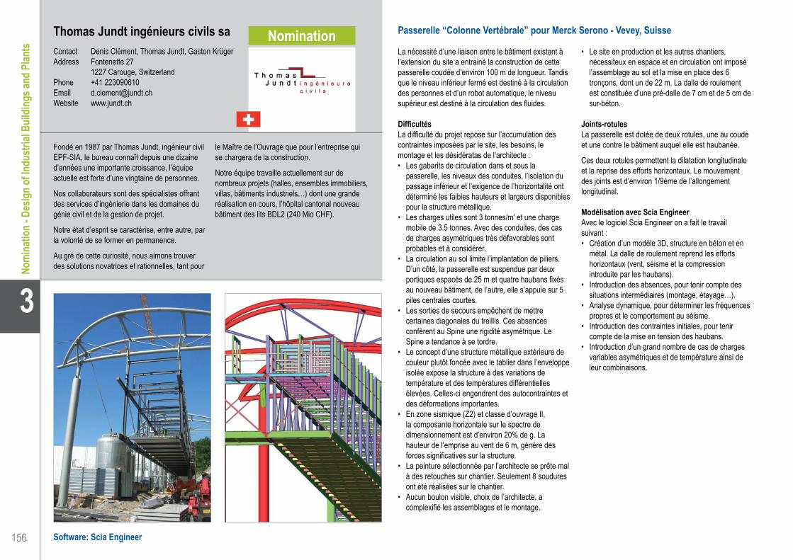
156
3
Thomas Jundt ingénieurs civils saContact Denis Clément, Thomas Jundt, Gaston KrügerAddress Fontenette 27 1227 Carouge, SwitzerlandPhone +41 223090610Email [email protected] www.jundt.ch
Passerelle “Colonne Vertébrale” pour Merck Serono - Vevey, Suisse
La nécessité d’une liaison entre le bâtiment existant à l’extension du site a entrainé la construction de cette passerelle coudée d’environ 100 m de longueur. Tandis que le niveau inférieur fermé est destiné à la circulation des personnes et d’un robot automatique, le niveau supérieur est destiné à la circulation des fluides.
DifficultésLa difficulté du projet repose sur l’accumulation des contraintes imposées par le site, les besoins, le montage et les désidératas de l’architecte :• Les gabarits de circulation dans et sous la
passerelle, les niveaux des conduites, l’isolation du passage inférieur et l’exigence de l’horizontalité ont déterminé les faibles hauteurs et largeurs disponibles pour la structure métallique.
• Les charges utiles sont 3 tonnes/m’ et une charge mobile de 3.5 tonnes. Avec des conduites, des cas de charges asymétriques très défavorables sont probables et à considérer.
• La circulation au sol limite l’implantation de piliers. D’un côté, la passerelle est suspendue par deux portiques espacés de 25 m et quatre haubans fixés au nouveau bâtiment, de l’autre, elle s’appuie sur 5 piles centrales courtes.
• Les sorties de secours empêchent de mettre certaines diagonales du treillis. Ces absences confèrent au Spine une rigidité asymétrique. Le Spine a tendance à se tordre.
• Le concept d’une structure métallique extérieure de couleur plutôt foncée avec le tablier dans l’enveloppe isolée expose la structure à des variations de température et des températures différentielles élevées. Celles-ci engendrent des autocontraintes et des déformations importantes.
• En zone sismique (Z2) et classe d’ouvrage II, la composante horizontale sur le spectre de dimensionnement est d’environ 20% de g. La hauteur de l’emprise au vent de 6 m, génère des forces significatives sur la structure.
• La peinture sélectionnée par l’architecte se prête mal à des retouches sur chantier. Seulement 8 soudures ont été réalisées sur le chantier.
• Aucun boulon visible, choix de l’architecte, a complexifié les assemblages et le montage.
• Le site en production et les autres chantiers, nécessiteux en espace et en circulation ont imposé l’assemblage au sol et la mise en place des 6 tronçons, dont un de 22 m. La dalle de roulement est constituée d’une pré-dalle de 7 cm et de 5 cm de sur-béton.
Joints-rotulesLa passerelle est dotée de deux rotules, une au coude et une contre le bâtiment auquel elle est haubanée.
Ces deux rotules permettent la dilatation longitudinale et la reprise des efforts horizontaux. Le mouvement des joints est d’environ 1/9ème de l’allongement longitudinal.
Modélisation avec Scia EngineerAvec le logiciel Scia Engineer on a fait le travail suivant :• Création d’un modèle 3D, structure en béton et en
métal. La dalle de roulement reprend les efforts horizontaux (vent, séisme et la compression introduite par les haubans).
• Introduction des absences, pour tenir compte des situations intermédiaires (montage, étayage…).
• Analyse dynamique, pour déterminer les fréquences propres et le comportement au séisme.
• Introduction des contraintes initiales, pour tenir compte de la mise en tension des haubans.
• Introduction d’un grand nombre de cas de charges variables asymétriques et de température ainsi de leur combinaisons.
Fondé en 1987 par Thomas Jundt, ingénieur civil EPF-SIA, le bureau connaît depuis une dizaine d’années une importante croissance, l’équipe actuelle est forte d’une vingtaine de personnes.
Nos collaborateurs sont des spécialistes offrant des services d’ingénierie dans les domaines du génie civil et de la gestion de projet.
Notre état d’esprit se caractérise, entre autre, par la volonté de se former en permanence.
Au gré de cette curiosité, nous aimons trouver des solutions novatrices et rationnelles, tant pour
le Maître de l’Ouvrage que pour l’entreprise qui se chargera de la construction.
Notre équipe travaille actuellement sur de nombreux projets (halles, ensembles immobiliers, villas, bâtiments industriels…) dont une grande réalisation en cours, l’hôpital cantonal nouveau bâtiment des lits BDL2 (240 Mio CHF).
Software: Scia Engineer
Thomas Jundt ingénieurs civils sa. . . . . . . . . . . . . . . . . . . . . . . . Spine Bridge at Merck Serono Plant - Vevey, Switzerland
Nomi
natio
n - D
esign
of In
dustr
ial B
uildin
gs an
d Plan
tsNomination

157
Project information
Short project description
Nemetschek Engineering User Contest 2011 - Category 3: Design of Industrial Buildings and Plants
3
Nomi
natio
n - D
esign
of In
dustr
ial B
uildin
gs an
d Plan
ts
Owner Merck Serono SAArchitect HWP Planungsgesellschaft mbH, Stuttgart, GermanyGeneral Contractor HEVRON SA, Courtételle, SwitzerlandEngineering Office Thomas Jundt ingénieurs civils sa, Geneva, SwitzerlandConstruction Period From June 2009 to November 2009Location Corsier-sur-Vevey, Switzerland
This project is about the Spine Bridge at the Merck Serono plant in Vevey, SwitzerlandFor the connection of two buildings, a two-level, 100 m long steel bridge was designed while complying with a large numbers of constraints (e.g. architectural ones, thermal loads, seismic conditions, assembling and erection, etc.). The bridge is hung to a new building by four straight cables, suspended to two very esthetical portal frames and supported by a few short piles. Two hinges situated at the bend and at the extremity (straight cable side) allow longitudinal dilatation whilst withstanding horizontal loads.
Spine Bridge at Merck Serono PlantVevey, Switzerland
Thomas Jundt ingénieurs civils sa. . . . . . . . . . . . . . . . . . . . . . . . Spine Bridge at Merck Serono Plant - Vevey, Switzerland

158
3
Cate
gory
3: D
esig
n of
Indu
stria
l Bui
ldin
gs an
d Pl
ants
Software: ESA-Prima Win, Scia Engineer
ACCESOM SARLContact Pierre ChapeyAddress 6 bis Bd Victor Hugo 78100 Saint Germain en Laye, FrancePhone +33 950559902Email [email protected]
Salle Paul Bocuse - EUREXPO - Lyon, France
La salle Paul Bocuse est un des éléments du nouveau Hall 99 qui vient d’être construit dans le parc des expositions EUREXPO, Lyon-Chassieu, constitué d’une douzaine de halls et de bâtiments annexes représentant environ 150.000 m2.
La salle Paul Bocuse est une salle multi-activités destinée à 3 usages différents :• Hall d’Exposition• Salle pour Conventions d’entreprises• Salle de spectacle (2.500 places sur gradins, en
partie fixes et en partie escamotables
Le Hall 99 dans son ensemble représente 11.000 m2 de surface couverte. La partie constituant la salle Paul Bocuse représente quant à elle 6.800 m2 (87 m * 78 m) sans aucun poteau intermédiaire. La hauteur sous charpente est de 12 m.
L’ossature est constituée d’une Méga-Poutre de 78 m de portée, sur laquelle s’appuient les fermes portant la couverture.
Cette Méga-Poutre a une section transversale trapézoïdale de hauteur variable, les faces étant inclinées de 15° vers l’extérieur. La partie basse est plane et située à 12 m du sol, la partie haute est constituée d’arcs de cercle, situés au dessus de la couverture. La hauteur de cette poutre varie de 4.50 m sur appuis à 11.00 m en partie centrale. Le sommet des arcs se trouve donc à 23 m du sol.
La Méga-Poutre est appuyée à l’une se ses extrémités sur une tour en béton, jouant également un rôle de stabilité horizontale, et à l’autre extrémité sur 2 poteaux chandelles de 12 m de hauteur. La charge sur les appuis est de l’ordre de 400 tonnes.Les membrures sont constitués de profilés HEM 300 en acier E36, avec renforts par plats caissonnant en partie ces HEM.La couverture d’une partie de la salle est traitée de manière à avoir des caractéristiques acoustiques renforcées pour pouvoir accueillir des concerts de musique amplifiée.
Dans la hauteur des treillis de charpente, un ensemble de passerelles et de catwalks permet l’accès en tout point de la structure pour y installer du matériel de scénographie (projecteurs, enceintes sonores)
Cette salle peut être découpée pour l’utilisation en deux salles indépendantes, grâce à un mur mobile implanté dans l’axe de la Méga-Poutre. Ce mur ayant lui même des caractéristiques acoustiques renforcées, son poids est d’environ 600 daN/ml et il impose d’avoir un support subissant une flèche très faible malgré la portée importante (78 m)
Dans un angle du hall, une entrée indépendante est aménagée sous une zone de 150 m2 en porte-à-faux complet.
Le hall complet représente environ 1.000 t de charpente, la partie constituant la salle Paul Bocuse comportant à elle seule environ 700 t, dont 230 t pour la seule Méga-Poutre.
Afin de gagner du temps lors du montage, le chantier complet devant être réalisé en moins d’un an, études d’exécution incluses ainsi que les installations techniques (chauffage, climatisation, électricité, etc.), la charpente devait être livrée très rapidement au couvreur pour pouvoir fournir un hall couvert aux autres corps d’état. La Méga-Poutre a été levée en 5 tronçons, posés sur étais provisoires, de manière à pouvoir installer une partie des fermes reposant sur la Méga-Poutre avant que celle-ci ne soit complètement assemblée.
Toutes les phases intermédiaires ont également été étudiées à partir du même modèle de calcul adapté à chaque fois.
ACCESOM est un cabinet d’Ingénieur-Conseil spécialisé en Structures Métalliques.
Il est basé à Saint-Germain-en-Laye, en banlieue ouest de Paris.
Il intervient à la fois en phase de conception des ouvrages, en tant que maître d’œuvre, en phase d’exécution, ou en expertise de structures existantes, sinistrées ou non.
Une part importante de son activité se situe dans le domaine industriel pour restructurer des unités de productions diverses ou les modifier afin
qu’elles soient adaptées à de nouveaux types de fonctionnement.
Il effectue également des études de chaudronnerie de type silos, cuves, filtres, etc. ainsi que des études de constructions à base de profilés minces.
ACCESOM SARL . . . . . . . . . . . . . . . . . . . . . . . . . . . . . . . . . . . . Paul Bocuse Hall - EUREXPO - Lyon, France

159
Project information
Short project description
Nemetschek Engineering User Contest 2011 - Category 3: Design of Industrial Buildings and Plants
Cate
gory
3: D
esig
n of
Indu
stria
l Bui
ldin
gs an
d Pl
ants
3
Owner COFILArchitect CRB Architectes - Jean-Philippe RicardGeneral Contractor CABROL Frères for Metallic StructureEngineering Office ACCESOM SARL for Metallic StructureConstruction Period From February 2010 to November 2010Location Lyon-Chassieu, France
The Paul Bocuse Hall is a multi-purpose building located in the exhibition centre EUREXPO near Lyon. It is a very versatile building with 3 different application possibilities: Exhibition Hall, Convention Centre or Show Hall. The surface is approximately 6.800 m2 (87 m * 78 m) without any column except in the exterior walls. The metallic structure of the roof is supported by a 78 m long Mega-Beam, which is a truss beam partly located in the hall and partly located above the roof. The weight of the whole structure is 700 tons, including 230 tons for the Mega-Beam itself.
Paul Bocuse Hall - EUREXPOLyon, France
ACCESOM SARL . . . . . . . . . . . . . . . . . . . . . . . . . . . . . . . . . . . . Paul Bocuse Hall - EUREXPO - Lyon, France

160
3
Cate
gory
3: D
esig
n of
Indu
stria
l Bui
ldin
gs an
d Pl
ants
Adem - Bureau d’étudesContact Stéphane Boulanger, François Denegre,
Veronika Balint, Jean-François Boeckmans, Damien Lixon, Martine Joarlette
Address Place de Flandre, 9 7000 Mons, BelgiumPhone +32 65 397260Email [email protected] www.adem.eu
Adem - Bureau d’études . . . . . . . . . . . . . . . . . . . . . . . . . . . . . . . Transit Store House of Limestone Quarry - Gaurain, Belgium
Stock Pile et Remontée Carrière - Gaurain, Belgique
Situé dans la carrière de Gaurain-Ramecroix, le projet concerne l’installation d’un nouveau stock pile couvert d’une longueur de 140 m pour une portée libre de 48 m et une hauteur de tas exploitable de 23 m, ainsi que les ouvrages nécessaires à son exploitation : galeries de reprises, transporteurs de remontée vers l’usine, tours d’angle, tours de concassage secondaires, massifs de support des nouveaux concasseurs, installation de filtres…
Méthode de travail - conception, calcul et dessinVu les impératifs de délai, les études génie civil ont été menées sur base de plans provisoires des installations (et donc de charges provisoires) pour lancer les adjudications des différents lots génie civil du projet et permettre la désignation des entrepreneurs (Jan De Nul pour une partie, Franki pour l’autre). A ce stade, les ouvrages étaient complètement modélisés et calculés avec Scia Engineer, leur coffrage déterminé et la faisabilité du ferraillage vérifiée. Le dessin 3D a été complètement réalisé sous Allplan. L’entrepreneur a pu être désigné sur base de plans de coffrage précis et d’une estimation du ferraillage. Au fur et à mesure de la finalisation des commandes des équipements mécaniques par le client, nous recevions les documents définitifs et pouvions vérifier (voire recalculer) les ouvrages et finaliser le ferraillage, afin de permettre au chantier de suivre son cours. Tout ceci s’est déroulé à flux extrêmement tendu. La conception des fondations a été étudiée au cas par cas pour chaque installation étant donné la particularité du site. D’une part, les assises des nouvelles installations étaient toutes différentes, avec des différences de niveau jusqu’à 50 m de hauteur. Certains ouvrages étaient donc posés à même la roche, d’autres sur des remblais de mauvaise qualité. D’autre part, les anciennes installations du site limitaient parfois l’encombrement disponible nécessaire pour assurer la stabilité de l’ensemble, ce qui a amené pour certains ouvrages à l’étude de solutions spécifiques (ancrages dans la roche, micro pieux, pieux…).
A propos de l’utilisation de la 3DPour le calcul comme pour le dessin, la 3D s’est réalisée extrêmement précieuse d’une part pour la précision qu’elle apporte dans un contexte géométrique aussi difficile et d’autre part pour la rapidité avec
laquelle elle peut être modifiée en gardant la cohérence de l’ensemble des facettes du projet. Au niveau calcul, le fait de disposer de modèles complets 3D nous a permis de répercuter rapidement les modifications de charges et géométrie pour en constater l’impact sur le dimensionnement et adapter coffrage et/ou ferraillage. Au niveau dessin, des ouvrages complexes ont pu être implantés et coffrés en toute cohérence dans un contexte difficile, les interactions des différents ouvrages vérifiées, et ceci sans même parler de la rapidité de modification suite aux évolutions du projet en cours d’exécution…
Le projet en quelques chiffres…12.000 m3 de béton, 847.000 kg de fers à béton, 2.5 km d’ancrages/pieux, 43.000 m3 de remblais/déblais
Un des ouvrages : galeries de reprise sous le stock Deux galeries, dimensions intérieures de 4.6 m x 5 m sur 138 m de long sous un stock de 23 m de haut assurent la reprise du calcaire. Ces galeries comportent des extracteurs sur leur dalle supérieure. Ils soutirent la matière première stockée en cône au dessus des galeries selon les besoin de l’usine, et les transporteurs intégrés dans les galeries les acheminent jusqu’à l’usine située 50 m plus haut.La détermination des efforts agissant sur ces galeries n’est pas triviale, l’ensemble pouvant être assimilé pour certaines sollicitations à un silo horizontal. Ces galeries doivent pouvoir supporter des pressions jusqu’à 37T/m2 (charge non pondérée). Vu leur longueur, ces galeries ont du être scindées en tronçons de 34 m séparés par des joints de dilatation permettant de reprendre les variations saisonnières de température.
L’évacuation des infiltrations éventuelles d’eau dans la galerie est assurée par une double pente de la dalle de fondation dans le sens longitudinal et transversal. Le dessin 3D devient ici un allié précieux pour calculer l’intersection de cette galerie dans le génie-civil d’un autre ouvrage de remontée, ayant lui-même des pentes différentes, ou pour la liaison de la galerie avec un tunnel de sortie de secours…
La définition précise du projet a permis son exécution dans les délais prévus et sans surprise de coffrage ou ferraillage sur chantier.
Adem est un bureau d’études pluridisciplinaire constitué principalement d’Ingénieurs Civils Architectes et Mécaniciens. Ses activités majeures sont la maîtrise d’œuvre de projets de construction au sens large et de conception d’installations industrielles. Les projets peuvent être suivis de l’esquisse de faisabilité jusqu’aux réceptions, avec la palette complète de services nécessaires, architecture, stabilité, techniques spéciales, coordination… Adem intervient ainsi directement pour des maîtres d’ouvrage, en sous-traitance de bureaux d’architecture ou d’ensemblier, ou encore en partenariat sur des
projets « Design & Build » par exemple.Startup issue de la Faculté Polytechnique de Mons. Adem a acquis au fil des années d’expérience une maîtrise très importante des calculs complexes, quels que soient les matériaux utilisés, les sollicitations (vibrations, séismes, fatigue, thermique…) et les codes de référence. Adem compte parmi ses clients autant des grands groupes industriels (CCB, HOLCIM, CARSID, AKZO, SOLVAY, AIR LIQUIDE…) que des PME, des bureaux d’architecture, des institutions publiques.
Software: Allplan Engineering, Scia Engineer
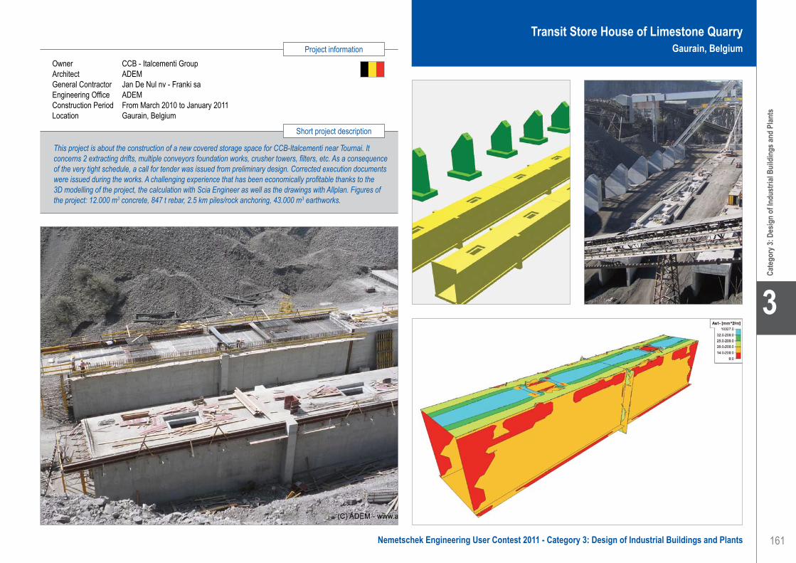
161
Project information
Short project description
Nemetschek Engineering User Contest 2011 - Category 3: Design of Industrial Buildings and Plants
Cate
gory
3: D
esig
n of
Indu
stria
l Bui
ldin
gs an
d Pl
ants
3
Owner CCB - Italcementi GroupArchitect ADEMGeneral Contractor Jan De Nul nv - Franki saEngineering Office ADEMConstruction Period From March 2010 to January 2011Location Gaurain, Belgium
Transit Store House of Limestone Quarry Gaurain, Belgium
Adem - Bureau d’études . . . . . . . . . . . . . . . . . . . . . . . . . . . . . . . Transit Store House of Limestone Quarry - Gaurain, Belgium
This project is about the construction of a new covered storage space for CCB-Italcementi near Tournai. It concerns 2 extracting drifts, multiple conveyors foundation works, crusher towers, filters, etc. As a consequence of the very tight schedule, a call for tender was issued from preliminary design. Corrected execution documents were issued during the works. A challenging experience that has been economically profitable thanks to the 3D modelling of the project, the calculation with Scia Engineer as well as the drawings with Allplan. Figures of the project: 12.000 m3 concrete, 847 t rebar, 2.5 km piles/rock anchoring, 43.000 m3 earthworks.

162
3
Cate
gory
3: D
esig
n of
Indu
stria
l Bui
ldin
gs an
d Pl
ants
Atelier P.H.A. s.r.o.Contact Hana Gattermayerová, Michal Škoch,
Lubica ObročníkováAddress Gabčíkova 15 182 00 Praha 8, Czech RepublicPhone +420 284 685 882Email [email protected] www.p-h-a.cz
Software: Scia Engineer
Atelier P.H.A. s.r.o.. . . . . . . . . . . . . . . . . . . . . . . . . . . . . . . . . . . . Extension of Proctor & Gamble Plant - Cairo, Egypt
Extension of Procter & Gamble Plant - Cairo, Egypt
Building geometry and structural system• Total steel weight: 278 tons• Dimensions: Height: +-16 m• Overall length: 36 m• Overall width: 23 m
The design was based on Eurocode standards. The static system of the structure is in transverse and longitudinal direction stabilized by bracing.
Design softwareThe static analysis was calculated using a 3D model in Scia Engineer software with Linear, Dynamic-seismic and Steel modules.
FoundationsThe structural design of basements was made by a local company based on outputs of our analysis.
Wind loadsThe wind load design was based on Uniform Building Code, vol. 2. and modified to the local Egyptian code• Wind basic speed 145 km/h• Wind pressure 0.996 kN/m2
Technological loadsThe technological load was given by a mechanical part of the project. The weight of the equipment is considered in two cases: a full and an empty one. These loads were combined for adverse effects on the structure. Horizontal forces in the model represented support reactions of piping, bucket elevators and hoists.
Seismic loadsThe seismic design was based on Eurocode EN1998The parametres: • Subsoil type - D• Direction - Horizontal• Coeff. accel. ag - 0.4• ag - design acceleration - 3.92266• q - behaviour factor - 4• S soil factor - 1.35
The mass participated values were more than 90% so we could assume that the calculation included higher significant modes. The seismic load was input by the
elastic response spectrum using 121 eigenmodes until frequency value 30 Hz.
Structural 3D modellingThe design process has been worked out in Scia Engineer. The structure has been completely modelled with 26.606 1D beam elements in 3D. Technology, live, dead and seismic loads have been applied to the load-bearing structure.
Calculation included several steps:1. A linear calculation using a 3D frame model for
the gravity loads (self weight, dead load, live load, technological load).
2. A dynamic-seismic analysis using a CQC type of the evaluation with a 5% damping.
3. A check of steel elements using a steel module for gravity load. The check of steel elements for seismic loads was calculated separately according to EC8.
Parameters of the structure were modified step by step according to the technological demands. The static system of the building is formed by frames with concentric diagonal bracing (dissipative zones in tension diagonals only) in transverse and longitudinal direction.
The systems of bracing were active tension diagonal bracings, in which the horizontal forces can be resisted by the tension diagonals only, neglecting the compression ones.
ConclusionIt was necessary to check a lot of different possibilities to find an optimised and economical solution. The project has been successfully completed and has become operational.
Atelier P.H.A. was founded in 1990. The structural engineering group has been a part of Atelier P.H.A. since 1994. P.H.A. deals with design tasks, preparation and implementation of investment projects, engineering activities and is an expert in the field of construction and real estate investments.They prepare expert opinions and participate in the exploration of load-bearing structures in existing constructions. Participation in opinions carried out on structures after the 2002 flood, opinion on the condition and measures taken on load-bearing structures in industrial,
high-rise apartment buildings, apartment building regeneration, opinions on the impact of emergency situations - fires, flooding - on load-bearing structures, building passports during reconstruction etc.P.H.A. can take part in cross-border projects in accordance with most standards: Eurocode, Fema-350, UBC97, СНИП and other specific national codes.P.H.A. regularly participates in professional seminars, as well as structural engineer meetings and conferences, lectures and publications in professional newspapers.

163
Project information
Short project description
Nemetschek Engineering User Contest 2011 - Category 3: Design of Industrial Buildings and Plants
Cate
gory
3: D
esig
n of
Indu
stria
l Bui
ldin
gs an
d Pl
ants
3
Owner Procter & GambleArchitect Chemoprag 3DEngineering Office Atelier P.H.A. s.r.o.Construction Period From January 2009 to March 2010Location Cairo, Egypt
Extension of Procter & Gamble PlantCairo, Egypt
Atelier P.H.A. s.r.o.. . . . . . . . . . . . . . . . . . . . . . . . . . . . . . . . . . . . Extension of Proctor & Gamble Plant - Cairo, Egypt
This project relates to the extension of the P&G plant of Cairo, Egypt. The building is designed to produce industrial agglomerates. The dimensions of this structure are 36 m x 23 m and it is 3 storeys high. The main challenge of the project was the coordination of the technology and the seismic stress check according to the Eurocode adapted to the local Egyptian code. The static system of the building is formed by frames with concentric diagonal bracing in transverse and longitudinal direction. The static analysis was performed using a 3D model in Scia Engineer to optimize the weight of the load-bearing steel structure.

164
3
Cate
gory
3: D
esig
n of
Indu
stria
l Bui
ldin
gs an
d Pl
ants
Software: Scia Engineer
Atelier P.H.A. s.r.o.Contact Hana Gattermayerová, Michal Škoch,
Lubica ObročníkováAddress Gabčíkova 15 182 00 Praha 8, Czech RepublicPhone +420 284 685 882Email [email protected] www.p-h-a.cz
Atelier P.H.A. s.r.o.. . . . . . . . . . . . . . . . . . . . . . . . . . . . . . . . . . . . Extension of Procter & Gamble Plant - Dammam, Saudi Arabia
Extension of Procter & Gamble Plant - Dammam, Saudi Arabia
Building geometry and structural systemTotal steel weight: 151 tonsDimensions height: +-16 mOverall length: 26 mOverall width: 10 m
The design was based on Eurocode standards. The structure is built inside the existing building and is prepared to support the structure for technological processes.
The static system of the structure is in transverse and longitudinal direction stabilized by bracings.
Design softwareThe static analysis was calculated using a 3D model in Scia Engineer with the Linear, Dynamic-seismic and Steel modules.
FoundationsThe structural design of the basements was made by a local company based on the outputs of our analyses.
Wind loadsWind load design was applied to the external surface of the building. There was no wind impact on the interior structure.
Technological loadsTechnological loads were given by a mechanical part of the project. Weights of equipments were considered in two cases: a full and an empty one. These loads were combined for adverse effects on the structure. Horizontal forces in the model represented support-reactions of piping, bucket elevators and hoists.
Seismic loadsSeismic design was based on Eurocode EN1998Parametres: Subsoil type - D• Direction - horizontal• Coeff accel. ag - 0.4• ag - design acceleration - 3.92266• q - behaviour factor - 4• S soil factor - 1.35
Mass participated values were more than 90% so we could assume that the calculation included significant higher modes. Seismic load was input by elastic response spectrum using 121 eigenmodes until frequency 30 Hz.
Structural 3D modellingThe design process has been worked out in Scia Engineer. The structure has been completely modelled by 14.633 1D beam elements in 3D. Technology, live, dead and seismic loads have been applied to the load-bearing structure.
The calculation included several steps:1. A linear calculation using a 3D frame model for
the gravity loads (self weight, dead load, live load, technological load).
2. A dynamic-seismic analysis using a CQC type of the evaluation with a 5% damping.
3. A check of steel elements using a steel module for gravity load. The check of steel elements for seismic loads was calculated separately according to EC8.
Parameters of the structure were modified step by step according to the technological demand. The static system of the building is formed by frames with concentric diagonal bracings (dissipative zones in tension diagonals only) in transverse and longitudinal direction.
The system of bracing was an active tension diagonal bracing, in which the horizontal forces can be resisted by the tension diagonals only, neglecting the compression ones.
ConclusionIt was necessary to check a lot of different possibilities to find an optimised and economical solution. The project has been successfully completed and has become operational.
Atelier P.H.A. was founded in 1990. The structural engineering group has been a part of Atelier P.H.A. since 1994. P.H.A. deals with design tasks, preparation and implementation of investment projects, engineering activities and is an expert in the field of construction and real estate investments.They prepare expert opinions and participate in the exploration of load-bearing structures in existing constructions. Participation in opinions carried out on structures after the 2002 flood, opinion on the condition and measures taken on load-bearing structures in industrial,
high-rise apartment buildings, apartment building regeneration, opinions on the impact of emergency situations - fires, flooding - on load-bearing structures, building passports during reconstruction etc.P.H.A. can take part in cross-border projects in accordance with most standards: Eurocode, Fema-350, UBC97, СНИП and other specific national codes.P.H.A. regularly participates in professional seminars, as well as structural engineer meetings and conferences, lectures and publications in professional newspapers.

165
Project information
Short project description
Nemetschek Engineering User Contest 2011 - Category 3: Design of Industrial Buildings and Plants
Cate
gory
3: D
esig
n of
Indu
stria
l Bui
ldin
gs an
d Pl
ants
3
Owner Procter & GambleArchitect Chemoprag 3DEngineering Office Atelier P.H.A. s.r.o.Construction Period From January 2009 to February 2010Location Dammam, Saudi Arabia
Extension of Procter & Gamble PlantDammam, Saudi Arabia
Atelier P.H.A. s.r.o.. . . . . . . . . . . . . . . . . . . . . . . . . . . . . . . . . . . . Extension of Procter & Gamble Plant - Dammam, Saudi Arabia
This project represents an extension of the P&G plant of Dammam, Saudi Arabia. The building is designed to produce industrial agglomerates. The dimensions are 26 m x 10 m and the building is 3 storeys high. The main challenge of the project was the coordination of technology and seismic dimensioning according to the Eurocode and the local Saudi Arabia code. The static system of the building is formed by frames with concentric diagonal bracings in transverse and longitudinal direction. The static analysis was performed using a 3D model realized in Scia Engineer to optimize the weight of the load-bearing steel structure.

166
3
Cate
gory
3: D
esig
n of
Indu
stria
l Bui
ldin
gs an
d Pl
ants
Software: Scia Engineer
Dipl.-Ing. S. Ryklin STATIK . . . . . . . . . . . . . . . . . . . . . . . . . . . . . Fire Protection Ceiling for Storage Hall - Hamburg, Germany
Fire Protection Ceiling for Storage Hall - Hamburg, Germany
CustomerHHLA - Hamburger Hafen und Logistik AG has decisively shaped Hamburg’s rise to become one of the world economy’s most important hubs. With innovative terminals, an ecologically exemplary transport network and comprehensive logistic services, today it stands for the intermeshing of global goods streams between Europe and overseas.
HHLA was founded as HFLG in 1885 to develop and run Speicherstadt (Warehouse District) of Hamburg. This was designed as the largest, most modern logistic centre in the world, and even at that time it was optimally intermeshed with networks of different carriers (sea, rail, and road). HHLA offers its clients an immense range of services along the entire logistics chain, from the quay wall in the overseas port to its customers in the hinterland.
The orderA big existing storage hall from the middle 80’s was indicated as a temporary storage place for the oncoming parts for the production of the Airbus. Due to the modern rules for fire protection the inner space of the hall has to be reduced to ensure the functionality of the sprinklers.
Because the statics of the hall did not consider the possibility of the additional load (about 30 kg/m2 required for the conventional solution with fire resistant plates), the client was looking for alternatives.A membrane ceiling with a fire resistance glass fabric spanned over the prestressed cable network was suggested. The additional load was assumed to be 1.0 kg/m2.
Technical dataThe existing hall consists of a filigree crossed steel framework beam roof with paired girder elements. The roof bases on the inner and outer facade steel columns net. The roof and side wall bracing stabilized the structure. The existing dimensions of the inner storage space were about 90.0 x 117.0 x 18.0 m. Due to the fire resistance rules, the required height of the storage hall has to be lower than 15.0 m.About 12.000 m2 fabric material and 6.000 m cables were needed. The biggest challenge was to consider
the existing roof geometry with all structural and additional elements such as 5 bands of light across the whole roof, existing old sprinklers and ventilation tubes, differently placed bracing, stability cables and truss elements. The new ceiling was not allowed to have more than 3% openings!
Software and modelScia Engineer was used for the processing of the whole project. The original execution plans were not found, but after very detailed surveying of all main parts of the structure the hall was completely build up as a 3D Model and the required geometry of the ceiling was settled. To optimize the fabrication and montage the ceiling was divided on the strips with two different widths due to the fabric production geometry. According to the settled strips the cable net with required additional facade beams, anchors and intermediate connections were planned.
Calculation and productionThe calculation, design and optimisation of the cable structure with the required additional facade beams was made according to the IIIrd order theory. The deflection of the ceiling has to be limited to 20 cm. Verification of the existing facade columns with additional load from the ceiling was done too. The next steps were the design of the connections for the new structure. At least design and confectioning of the fabric strips with connections to the cable net and to the existing structure was processed.
ExecutionThe structure was completely planned und produced in 3 months. The General Constructor was Planex Technik in Textil GmbH. Nevertheless the optimisation, about 280 different types of fabric stripes were derived from the 3D model due to geometrical demands. The total project cost amounted to approximately 370.000 Euros.
Sergej Ryklin - Born in 1963 in Moscow• 1981-1985: Civil Engineering; “Bridges/
Tunnels”• Since 1993: Structural designer and verifier by
“Römhild & Hecker” Consulting Engineers in Landau, Germany
• Since 1997: Structural designer• 2008-2009: Master Study on the Institute for
Membrane and Shell Technologies, Anhalt University of Applied Sciences, Germany
Range of Capacity: Planning and optimization of Steel, Aluminium, Solid, Composite, Timber
and Membrane Structures, Project consultancy, Building physics calculations, Dynamics calculations, Project verification.
Philosophy: Flexibility in planning due to integral 3D Design with the ability to find feasible and low-cost solutions already in draft stage.
Experience: Residential and industrial buildings, parking spaces, pedestrian bridges, swimming pools, silos, membranes, etc.
References: Daimler, John Deere, SAP, DB, etc.
Dipl.-Ing. S. Ryklin STATIKContact Sergej RyklinAddress Liselottestrasse 17 69123 Heidelberg, GermanyPhone +49 6221830673Email [email protected] www.ryklin.eu

167
Project information
Short project description
Nemetschek Engineering User Contest 2011 - Category 3: Design of Industrial Buildings and Plants
Cate
gory
3: D
esig
n of
Indu
stria
l Bui
ldin
gs an
d Pl
ants
3
Fire Protection Ceiling for Storage HallHamburg, Germany
Dipl.-Ing. S. Ryklin STATIK . . . . . . . . . . . . . . . . . . . . . . . . . . . . . Fire Protection Ceiling for Storage Hall - Hamburg, Germany
Owner HHLA HamburgArchitect Dipl.-Ing. T. Beyer / Dipl.-Ing. S.Ryklin General Contractor Fa. Planex Technik in Textil GmbHEngineering Office Dipl.-Ing. S.Ryklin STATIKConstruction Period From April 2009 to July 2009Location Hamburg, Germany
The presented project is about the ceiling renovation of a storage hall for Airbus parts of the 80’s in accordance with the modern rules for fire protection. The inner space of the hall is reduced, the membrane ceiling is provided with a fire resistant glass fabric spanned over a prestressed cable network and the height had to be lower than 15 m. About 12.000 m2 of fabric material and 6.000 m of cables were needed. The biggest challenge was to consider the existing roof geometry with all elements such as 5 bands of light across the whole roof, sprinklers and ventilation tubes, differently placed bracing, stability cables and truss elements.

168
3
Cate
gory
3: D
esig
n of
Indu
stria
l Bui
ldin
gs an
d Pl
ants
Edibo nv. . . . . . . . . . . . . . . . . . . . . . . . . . . . . . . . . . . . . . . . . . . . Showroom and Workshop Merinsky - Sint-Truiden, Belgium
Edibo nvContact Jan Caelen, Jens CannaertsAddress Maatheide 1302 3920 Lommel, BelgiumPhone +32 11541159Email [email protected] www.edibo.be
Showroom en Werkplaats Merinsky - Sint-Truiden, België
Edibo zorgde voor de structurele berekening van het gebouw.
FunderingHet volledige gebouw staat op sokkels die op hun beurt de krachten afdragen naar de grindkernen. Voor het dimensioneren van de grindkernen zijn de reactiekrachten aan de voet van de kolommen gebruikt. Deze reactiekrachten hebben bepaald hoeveel grindkernen onder elke sokkel moesten worden geplaatst.
OntwerpeisenVoor de staalberekening moest er rekening gehouden worden met een aantal factoren:• Zo weinig mogelijk windverbanden achter het glas• De showrooms moesten ontworpen worden naar de
brandeisen zoals beschreven in het KB 19/12/1997 (bijlage 2: lage gebouwen)
• De toren moest op zo’n slank mogelijke manier worden uitgevoerd
Structurele berekeningHet glas in het project zorgde ervoor dat de structuur niet veel mocht vervormen. Dit om te voorkomen dat de vitrines zouden gaan barsten en vervolgens breken. Daarom moet de vervorming van het gebouw tot een absoluut minimum worden beperkt. De uitwijking wordt verhinderd door de aanwezigheid van windverbanden. De windverbanden situeren zich in het dak en worden via het dak afgeleid naar de achtergevel en de toren die zich in het midden van het project bevindt. Op deze manier werd ervoor gezorgd dat er achter het glas geen windverbanden moesten worden geplaatst.
Voor het berekenen van de brandeisen werd er geopteerd om de module Scia Engineer te gebruiken. Dit om er zeker van te zijn dat de structuur een halfuur brandwerend zou zijn. Van de delen waarbij er een tussenvloer is voorzien, moet men de onderste delen brandwerend schilderen.
De verbindingen tussen de liggers en kolommen werden allemaal in Scia Engineer ontworpen. Op deze manier kunnen al de verbindingen de nodige krachten opnemen.
De brandmuur tussen de werkplaats en de showroom zorgt voor een ontdubbelde structuur. Hierdoor vallen de brandeisen van de werkplaats onder bijlage 6.
Technische gegevens van het project• Fundering: grindkernen• Maximale overspanning: 20 m• Maximale hoogte: 14 m• Vide: 12 m hoogte• Showrooms: 2• Werkplaats: 1
BesluitDe toren in het midden van het gebouw is de eye-catcher van het project en zorgt tevens ook voor stabiliteit.
Door de flexibiliteit van Scia Engineer kon er snel informatie worden uitgewisseld met de klant. Hierdoor konden aanpassingen op een efficiënte manier worden uitgevoerd.
De firma Edibo (Lommel) is gespecialiseerd in het bouwen van bedrijfsgebouwen en kantoren. Edibo bouwt zowel nieuwbouw-, uitbreidings- als renovatieprojecten “sleutel-op-de-deur” en dit zowel in staal, beton als hout. Reeds meer dan 25 jaar bouwt Edibo schitterende referentie-projecten in diverse sectoren: multifunctionele distributiecentra voor de logistieke sector, productie- en bedrijfsruimten voor industrie (oa voedingsindustrie), KMO en multinationals, kantoorcomplexen en showrooms voor handel en dienstverlening. Edibo onderscheidt zich door zijn toegevoegde waarde. Vanaf de ontwerp-
en studiefase wordt er meegedacht met de bouwheer. De interne studiedienst staat garant voor stabiliteitsstudies, fire safety engineering en bouwtechnische optimalisatie. Een oordeelkundige projectuitvoering en kwalitatieve afwerking wordt ondersteund door het ISO 9001 kwaliteitslabel en de OHSAS 18001 veiligheidscertificering.Edibo tracht steeds bedrijfsgebouwen met “onderscheidend karakter en uitstraling” af te leveren. Het realiseren van een stimulerende werkomgeving binnen het programma en het budget van de bouwheer ligt vervat in het motto “Building dreams on facts”.
Software: Scia Engineer

169
Project information
Short project description
Nemetschek Engineering User Contest 2011 - Category 3: Design of Industrial Buildings and Plants
Cate
gory
3: D
esig
n of
Indu
stria
l Bui
ldin
gs an
d Pl
ants
3
Showroom and Workshop MerinskySint-Truiden, Belgium
Edibo nv. . . . . . . . . . . . . . . . . . . . . . . . . . . . . . . . . . . . . . . . . . . . Showroom and Workshop Merinsky - Sint-Truiden, Belgium
Owner Merinsky AlbertinoArchitect Alex SomersGeneral Contractor Edibo nvEngineering Office Edibo nvConstruction Period From September 2010 to 2011Location Sint-Truiden, Belgium
This project is about the new showroom annex workshop of Garage Merinsky, Sint-Truiden.One of the complex aspects of the design was the horizontal deformation of the building, because of the presence of large glass show windows.A special challenge was the construction in the middle of the building where we needed to make a slender tower. The structure is executed as a 3D model in Scia Engineer. Thanks to this model it was possible to create a flexible and easy building structure.

170
3
Cate
gory
3: D
esig
n of
Indu
stria
l Bui
ldin
gs an
d Pl
ants
Software: Scia Engineer
Biomass Installation Electrabel - Nijmegen, The Netherlands
IntroductionTwo years ago, Geldof Metaalconstructie started the engineering and construction of the largest and greenest project in its history: a biomass processing unit for the Electrabel, GDF SUEZ Group, power station in Nijmegen, the Netherlands. Geldof is supplying a total solution for this to Electrabel. Because of the extent of the project and the time pressure Geldof has subcontracted engineering office Establis for the study of the civil works.
About the projectThanks to the biomass processing unit, the power station in Nijmegen can increase the percentage of biomass burned to 25%, with the emphasis on a greater use of sustainable energy sources. Each year the installation processes 500.000 tonnes of wood dust, as a result of which Electrabel can supply some 200.000 people with green power.
With this project Geldof has demonstrated that it is a prominent player in the field of biomass installations. Thus it provides a total solution in which the energy efficiency of each component is important: from the mechanical transport system to the implementation of the new installation in the already existing power station, from the crushing of the biomass to the carrying out of all safety and operational studies.
The project was massive both from the construction and the engineering point of view. Geldof and Establis opted to execute the stability calculations for the civil part and steel structure in Scia Engineer, considering the complexity of the installation. Geldof built, placed and supervised the placing of more than 500 pile foundations, the construction of the mechanical transport system with a capacity of 600 tonnes per hour, 2 large storage silos each with a capacity of 5.000 m³, the crushing of the biomass into wood dust, the dust removal installation, the pneumatic transport to the 24 burners, all civil engineering work and all electrical aspects. In addition to the mechanical and electrical components, safety was a particular challenge. After all, it’s wood dust that is injected into the burners.
One of the greatest challenges of the project was the fact that the existing piles of an older, torn down plant
on the construction site, never were removed. There was no information about the bearing capacity of these piles so the decision was made to use new piles for the foundations.
Use of Scia EngineerEstablis used Scia Engineer to make a complete 3D model of the basement under the silos and the foundation of the silos. The load of the biomass on the foundation of the silos is 170 tonnes per m² and the dead load of the silos is 36.2 tonnes per meter. Thanks to the use of Scia Engineer it was possible to try out several different grids for the piles to come to the most economic solution. Every pile has a bearing capacity of 160 tonnes and is used optimal. In total there were 235 piles used for the foundation of the silos.
During the execution of the new piles it became clear that the pile plans of the old piles weren’t completely correct and various piles had to be replaced. Once all the piles were executed and measured by a surveyor the 3D model could be finalized and the reinforcement could easily be calculated.
It is common knowledge that dust can be an explosion risk and for this reason special safety measures were studied and developed: from extra compartmentalisation and pressure relief systems through a spark detection system with water nebulisation to the more everyday fire alarm system and fire extinguishing installation.
With this project Geldof and Establis have proven that they are fully committed to a sustainable, ecological and more environmentally aware society and that they have a far-reaching know-how in the field of green energy solutions.
Establis . . . . . . . . . . . . . . . . . . . . . . . . . . . . . . . . . . . . . . . . . . . . Biomass Installation Electrabel - Nijmegen, The Netherlands
Establis Group is an engineering company, specialized in creative design and calculation of building structures, with a good sense of reality. Geldof has subcontracted Establis for the study of the civil works.
Geldof is a worldwide supplier of industrial components and turnkey projects for the storage, handling and processing of solids, liquids and gases. Furthermore, Geldof is also specialised in the construction of storage tanks and pressure vessels. Geldof helps its customers to achieve their strategies in Europe or elsewhere in the
world by providing total solutions. Steel is the basis of every device made by Geldof. Supported by integrated project management, business development and an efficient production unit, the company is able on this basis to continually provide top-quality and durable projects.
Geldof serves a wide range of sectors: the oil, gas and energy industries, chemicals, biochemicals and petrochemicals, metal working, mining, the bulk food sector, etc. In this respect, Geldof operates both directly with final customers and via agencies.
EstablisContact Bart MaertenAddress Beversesteenweg 612 8800 Roeselare, BelgiumPhone +32 51 43 12 00Email [email protected] www.establis.eu
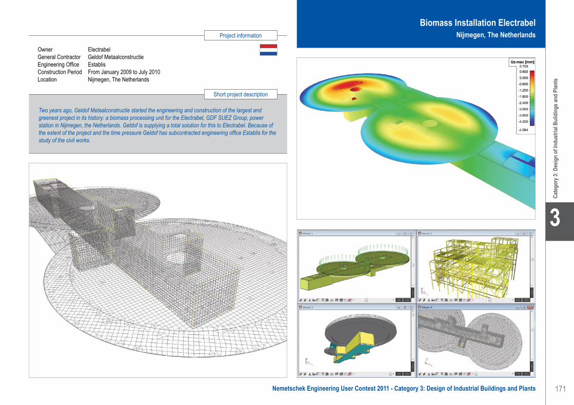
171
Project information
Short project description
Nemetschek Engineering User Contest 2011 - Category 3: Design of Industrial Buildings and Plants
Cate
gory
3: D
esig
n of
Indu
stria
l Bui
ldin
gs an
d Pl
ants
3
Owner ElectrabelGeneral Contractor Geldof MetaalconstructieEngineering Office EstablisConstruction Period From January 2009 to July 2010Location Nijmegen, The Netherlands
Two years ago, Geldof Metaalconstructie started the engineering and construction of the largest and greenest project in its history: a biomass processing unit for the Electrabel, GDF SUEZ Group, power station in Nijmegen, the Netherlands. Geldof is supplying a total solution for this to Electrabel. Because of the extent of the project and the time pressure Geldof has subcontracted engineering office Establis for the study of the civil works.
Biomass Installation ElectrabelNijmegen, The Netherlands
Establis . . . . . . . . . . . . . . . . . . . . . . . . . . . . . . . . . . . . . . . . . . . . Biomass Installation Electrabel - Nijmegen, The Netherlands

172
3
Cate
gory
3: D
esig
n of
Indu
stria
l Bui
ldin
gs an
d Pl
ants
Koffietoren - Zeebrugge, België
ProjectHet betreft de bouw van een nieuwe industriële plant voor het sorteren en opslaan van groene koffiebonen. De opslagruimte is een geconditioneerde ruimte, volledig opgebouwd in beton. Het productiegedeelte is als torengebouw uitgevoerd in staal, met errond een stalen luifel. In het productiegedeelte worden de koffiebonen in bulksilo opgeslagen om daarna via een aantal machines (weegschalen, zeven, optische sorteermachines, etc.) gesorteerd te worden en in zakken verdeeld.
OntwerpBij het ontwerp van de toren moest rekening worden gehouden met enkele uitzonderlijke parameters:1. De windlasten in het kustgebied op 32 m hoogte zijn
niet te verwaarlozen. Ook de opwaartse winddruk op de luifel is belangrijker dan de neerwaartse belasting op de luifel.
2. De toren bestaat enerzijds uit een silogedeelte en anderzijds uit de machines errond en erboven. De silowanden en afdekplaten mochten niet belast
worden. Er moest dus volledig rond de silo’s gebouwd worden: vrije ruimte rondom de silo’s en een onafhankelijke buitenwand, vrije ruimte boven de silo’s en erboven vloeren met grote overspanningen.
3. In de zones van de machines komen lukraak machine-ondersteuningen en openingen in de vloer. Dit, in combinatie met de nodige windverbanden in de vloer, zorgt voor een puzzel van hoofdliggers, secundaire liggers, tertiaire liggers, etc. en diagonalen.
4. Sommige machines, in het bijzonder de zeven, zorgen voor horizontale en vertikale trillingen. Andere machines, zoals de optische sorteerders, zijn zeer gevoelig voor die trillingen. Deze 2 eisen moeten met elkaar verzoend worden. Er werden stukken vloer voorzien als betonvloeren. Dit om massa in de toren te brengen om de trillingen te dempen. De eigenfrequenties van de vloerliggers werden nagekeken om ervoor te zorgen dat ze niet in resonantie gaan met de machines. Waar mogelijk werden machines die veel trillingen geven of zeer trillingsgevoelig zijn rechtstreeks op de funderingsplaat verankerd, los van de structuur van het gebouw.
Naast de toren staat een onafhankelijke stalen trappentoren. Deze trappentoren is autostabiel bij brand. Een tweede vluchtweg zit in de toren zelf via kooiladders.
Scia EngineerDe lastendaling voor de toren is vrij complex omwille van de verschillende vloerniveaus, verschillende lasten en het grote aandeel van de windbelasting in de belasting op de fundering.
Door gebruikt te maken van de 3D-module van Scia Engineer kunnen alle lasten afzonderlijk ingegeven worden en worden alle belastingscombinaties meegerekend. Voor het ontwerp van de funderingsplaat op palen werd het model van de staalstructuur geïmporteerd, zodat ook meteen alle belastingscombinaties op de funderingen nagerekend worden. Voor het verder detailleren van de staalstructuur werd dan de funderingsplaat weggelaten.
Establis Group is een engineeringsbureau, gespecialiseerd in het creatief ontwerpen en berekenen van bouwkundige structuren, met een bewust gevoel voor realiteit. We houden ook van vlotte communicatie. Establis speelt vandaag de hoofdrol in een boeiend en groeiend succesverhaal.
Om de groei van Establis te bestendigen, was een nieuwe structuur nodig. Nu is Establis Group een feit.
Establis Group overkoepelt Establis Roeselare, Establis Antwerpen, Establis Leuven
(het vroegere IKDV) en Asysto. Hierdoor kunnen onze ingenieurs voortaan ook grotere nationale en internationale projecten aan.
Vandaag is Establis Group een stabiliteitsbureau met sterke fundamenten, klaar voor de toekomst.
Wij worden graag uw betrouwbare partner voor slimme en creatieve stabiliteitsoplossingen. Iedereen spreekt dezelfde taal als het over stabiliteit gaat. De taal van Establis.
EstablisContact Bart MaertenAddress Beversesteenweg 612 8800 Roeselare, BelgiumPhone +32 51 43 12 00Email [email protected] www.establis.eu
Establis . . . . . . . . . . . . . . . . . . . . . . . . . . . . . . . . . . . . . . . . . . . . Coffee Sorting Tower - Zeebrugge, Belgium
Software: Scia Engineer

173
Project information
Short project description
Nemetschek Engineering User Contest 2011 - Category 3: Design of Industrial Buildings and Plants
Cate
gory
3: D
esig
n of
Indu
stria
l Bui
ldin
gs an
d Pl
ants
3
The project is about a completely new industrial plant for sorting and warehousing green coffee beans in Zeebrugge. The plant contains an office building, a warehouse and a sorting installation with canopy roof all around. To keep ideal climate conditions, the warehouse is entirely built up with concrete elements (structure, roof and walls). The sorting installation is a steel tower with bulk silos and all sorts of machines (weighers, optical sorters, separators, etc.) where the beans are sorted and bagged.The structure was designed by Establis and built by the company Cordeel.
Coffee Sorting TowerZeebrugge, Belgium
Owner EficoArchitect ArchibetaGeneral Contractor CordeelEngineering Office EstablisConstruction Period From December 2008 to April 2010Location Zeebrugge, Belgium
Establis . . . . . . . . . . . . . . . . . . . . . . . . . . . . . . . . . . . . . . . . . . . . Coffee Sorting Tower - Zeebrugge, Belgium

174
3
Cate
gory
3: D
esig
n of
Indu
stria
l Bui
ldin
gs an
d Pl
ants
FRANCEMETALContact Houzeau Frédéric, Raluca StoïcaAddress ZI RN 10 40530 Labenne, FrancePhone +33 5594515145Email [email protected] www.galco-cm.com
Hangars et bureaux SCI Isehos - La Brillane, France
Le projetLe projet de la SCI Isehos était la réalisation de hangars et de bureaux à La Brillane dans le 04.Malgré sa taille modeste (400 m²), il représentait alors un défit technique dans la mesure où l’ensemble des éléments de la charpente métallique sont des éléments minces d’épaisseur maximum 4 mm (à l’exception des goussets). Par ailleurs, l’ensemble de la justification de ce dossier devait être réalisée suivant les Eurocodes et plus particulièrement la partie 1.3 des Eurocodes 3.
Description des bâtimentsLe projet est constitué de 2 bâtiments de largeur 10 mètres et longueur 20 mètres. Dans le plus grand bâtiment (hauteur 6,5 mètres), une mezzanine est intégrée afin d’aménager un espace bureau. Le second bâtiment comporte une partie atelier et une partie garage pour les véhicules de l’entreprise.
L’ensemble de la structure (portiques, pannes, lisses, et contreventements sont tous en profil pliés de forme Z allant de 2 à 4 mm d’épaisseur. La mezzanine est réalisée en caisson double Cé reconstitué par soudage.
Les bâtiments sont isolés avec des panneaux sandwiches d’épaisseur 40 mm.
ApprocheLes efforts sismiques étaient seulement dimensionnants pour le bâtiment avec mezzanine (surcharge 350 kg/m², zone sismique II, classe B) ; en effet pour le second bâtiment la neige et le vent sont prépondérants.
Une déconnexion de 6 cm a cependant été réalisée entre les deux bâtiments afin de limiter l’impact des vibrations.
La détermination des charges de neige et vent est réalisée suivant les Eurocodes 1, les charges sismiques suivant les PS92.La justification des sections et des assemblages est faite suivant les Eurocodes 3 et 8.La principale difficulté était de trouver un type de section pour les portiques répondant aux exigences des Eurocodes, et ce en restant dans des épaisseurs faibles et sans se tourner vers des portiques traditionnels.
Utilisation de Scia EngineerScia Engineer a dans un premier temps permis de modéliser simplement et rapidement la structure en 3D.Dans un second temps, nous avons réalise uniquement le calcul sismique et nous avons rapidement constaté une insuffisance au niveau du portique en terme de stabilité et de résistance.
Nous avons résolu ce problème en doublant notre profil Z par un autre profil ; ainsi le portique était validé. La souplesse d’utilisation de Scia Engineer nous a permis d’essayer un grand nombre de profils différents, et d’accéder facilement aux résultats à l’aide du module de contrôle acier.
Ensuite nous avons introduit l’ensemble des cas de charges et validé l’ensemble des sections sélectionnées pour ce projet.Enfin, le logiciel nous a également permis de dimensionner nos assemblages et nos pieds de poteaux à l’aide de son module éléments finis.La note de calculs a ensuite été validée par le bureau de contrôle SOCOTEC.
Le groupe FRANCEMETAL regroupe 4 filiales et 110 collaborateurs :• France : FM Sud à Labenne (40) et FM Nord à
Marboué (28). Elles disposent respectivement de sites de production de 2700 m² et 4000 m².
• Portugal : Galcopor à Tabua dispose de 2000 m² de surface de production.
• Roumanie : Galcorom à Bucharest est une agence commerciale.
Notre longueur d’avance, c’est 30 ans de pliage en grande longueur jusqu’à 14 mètres. Sous la marque GALCO, FRANCEMETAL commercialise
des bâtiments modulaires répondant à des besoins très variés: surfaces de stockage, ateliers, bureaux…
Sous la marque KIKAFFICH, nous fabriquons et distribuons une gamme complète de panneaux d’affichage. La satisfaction et la confiance de nos clients font aujourd’hui de la marque Kikaffich le leader national des panneaux d’affichage.De part ses moyens de production et d’approvisionnement, FRANCEMETAL est aussi un sous-traitant d’envergure réalisant tout profil plié, poinçonné, grugé, et soudé selon vos besoins.
FRANCEMETAL . . . . . . . . . . . . . . . . . . . . . . . . . . . . . . . . . . . . . SCI Isehos Buildings - La Brillane, France
Software: Scia Engineer

175
Project information
Short project description
Nemetschek Engineering User Contest 2011 - Category 3: Design of Industrial Buildings and Plants
Cate
gory
3: D
esig
n of
Indu
stria
l Bui
ldin
gs an
d Pl
ants
3
Owner FunexiaArchitect Arditti JumelGeneral Contractor Arditti JumelEngineering Office FRANCEMETALConstruction Period From March 2009 to April 2009Location La Brillane, France
The project of the « SCI Isehos » consisted of realising 2 buildings of which one was divided into two parts; one part was used as a storage room and the other part was used as office buildings.The technical challenge for this project was to realise buildings made of thin steel elements. The maximum thickness used was 4 mm. Moreover, the calculations for this case had to be carried out according to Eurocodes standards, especially Part 1.3 of Eurocode 3.
SCI Isehos BuildingsLa Brillane, France
FRANCEMETAL . . . . . . . . . . . . . . . . . . . . . . . . . . . . . . . . . . . . . SCI Isehos Buildings - La Brillane, France

176
3
Cate
gory
3: D
esig
n of
Indu
stria
l Bui
ldin
gs an
d Pl
ants
Istroenergo group a.s.Contact Jaroslav KonôpkaAddress Rozmarínová 4 P.O.Box 157 934 01 Levice, Slovak RepublicPhone +421 36 6376 111Email [email protected] www.ieg.sk
Heat Recovery Steam Generator - Wilton, United Kingdom
GeneralThe boiler design is based on state of the art technology to deliver high pressure steam (98 bar) for steam consumers in a big refinery plant, in Wilton, Teesside, North-East of England. A boiler with supplementary firing is installed downstream of the industrial heavy duty Gas Turbine Frame 6B (General Electric). The nominal output from the boiler is steam with the parameters: 98 bar, 385° C, 180 t/hr. The final customer and operator of the boiler is SembCorp. The erection started in 2008 and has been finished successfully in 2009.
IEG was the designer and supplier of HRSG, HRSG platforms, staircases, stack and feed water system included feed water tank (FWT) with de-aerator, feed water pumps, exchangers, pipes with valves and a supporting steel structure. The HRSG structure with platforms and staircase has as dimensions 20 x 11.6 m and the top platform is situated 20.6 m aboveground. The FWT structure has as dimensions 12 x 6 m and the top platform is situated 11.6 m aboveground. The total weight of the steel structure is almost 300 tons.
Description of the ConstructionHRSG, FWT and steel structure platforms were interconnected so that they allow relative displacement of each structure part. Except for the boiler, all the structures were designed with bolted interconnections, steel columns and galvanized beams.
Heat Recovery Steam GeneratorThe HRSG consists of two heat exchanger modules and two parts of flue gas ducts. All parts of the HRSG were calculated separately. The main module structure consists of a frame construction with four massive columns. In each module are placed finned tubes which are hung at top of the main frame construction. In the modules are steel plates to guide the finned tubes. The staircase is located on the left side of the HRSG, platforms and ladders are located on the right side. Two platforms are extended around the stack and are joined to the staircase, so it is easy to get from one side of the HRSG to the other. Platforms accessing the boiler drum and steam silencers are situated on the top of HRSG. The stack is equipped with a 360° platform at +40.0 m
above ground, to provide access to different measuring points/nozzles on the flue-gas.
CalculationsVarious loads were determined: self-weight, imposed load, load of finned tubes, water tank at top of module, wind, water in tank and pipes, overpressure, loads from steam pipes, loads from connected structures, insulation weight, etc.
Calculations of various combinations were extended to transport and erection positions. During transport in horizontal position and the erection on site, the HRSG modules were equipped with a special construction which was able to keep each module in a correct position and safe deformation.
Feed Water Tank structureThe FWT construction is a main frame structure for the feed water tank, weighing 60 t with water, placed on a platform 11.6 m above ground. The structure has another platform +6.0 m where heat exchangers and pipes are placed. Pipes which are led at the FWT construction are supported or hung on the main structure.It was requested to keep one axis of columns from the road side without any bracing to ensure easy installation of technology and pipes.
The FWT construction was manufactured in Slovakia and transported to the site in several parts. The erection was swift due to the prefabricated construction and the fact that all connections were bolted.
CalculationsVarious loads, such as self-weight, water tank weight, wind, imposed load, pipes, other technology and trolley cranes, were calculated.
Scia Engineer software, introduced to IEG short time before the beginning of the project, was used for structural calculations. Since then it has become our main CAE software, a powerful tool for calculating all power plant steel constructions. The compatibility with various CAD software, Tecla Structures and other programs makes it a very progressive aid for designing our actual and future projects.
The company IEG was established in 1992. It is aimed at power engineering. Since the very beginning of IEG, the goal was to build up its own know-how, with the capability to provide integrated services up to turn-key deliveries.
Today, IEG is one of the most important Slovak exporters of power generation technology and projects.
IEG is building up this position by developing its own know-how in the areas of engineering, project management and the construction of power generation units.
The main IEG work scope• World class in engineering and complexity of
power plant design and deliveries• Development and design of projects and
equipment• Engineering and technical documentation
preparation, supervision, technical assistance and licences
• Manufacture, purchase, completion of power equipment, delivery of power equipment and turn-key delivery of power plants
• Erection and commissioning• Guarantee and after-guarantee services
Software: Scia Engineer
Istroenergo Group a.s.. . . . . . . . . . . . . . . . . . . . . . . . . . . . . . . . . Heat Recovery Steam Generator - Wilton, United Kingdom

177
Project information
Short project description
Nemetschek Engineering User Contest 2011 - Category 3: Design of Industrial Buildings and Plants
Cate
gory
3: D
esig
n of
Indu
stria
l Bui
ldin
gs an
d Pl
ants
3
Owner SembCorbGeneral Contractor Aker KvaernerEngineering Office Istroenergo Group, Inc.Construction Period From 2008 to 2009Location Wilton, Teesside, United Kingdom
The project is about a heat recovery steam generator and a feed water tank structure. IEG is the engineering company for the platforms, staircases, stack and feed water system including a feed water tank with a de-aerator, feed water pumps, pipes, and supporting steel structures. The boiler design is based on state of the art technology, to deliver high pressure steam (98 bar) in a big refinery plant. A boiler with supplementary firing is installed downstream of an industrial heavy duty Gas Turbine Frame 6B. The nominal output of the boiler is steam with the parameters: 98 bar, 385° C, 180 t/hr.
Heat Recovery Steam GeneratorWilton, United Kingdom
Istroenergo Group a.s.. . . . . . . . . . . . . . . . . . . . . . . . . . . . . . . . . Heat Recovery Steam Generator - Wilton, United Kingdom

178
3
Cate
gory
3: D
esig
n of
Indu
stria
l Bui
ldin
gs an
d Pl
ants
Software: Scia Engineer
Milk Factory - Chania, Greece
Introduction to the projectThis project is about the New Milk Factory of Mr. Sxetakis Nikolaos. The construction will start in the early part of 2011 and is situated on Crete, the largest island of Greece. The factory is composed of three separate buildings. The overall acreage of the construction will be about 1.000 m2.
Description of the projectThe whole structure consists of three separate buildings. The main building (about 800 m2) is designed out of steel and it includes:1. The acceptance room of the milk2. The chemical-checks room3. The production area4. The separate rooms for the storage of the end
products5. Offices
Connected to the main building there will be two more buildings:a. The boiler house (about 120 m2)b. The building that will accommodate the waste water
treatment equipment (about 90 m2)
Main buildingThe distance between the columns of each frame is about 13 m. We designed this building out of steel. The distances between the frames are 5.8 m. At both sides of the building there are two small cantilevers for the cold-air pumps. The dimensions of the building are 13 m x 56 m and the height about 6 m. We used HEA280 for the columns, IPE330 for the beams and SHS cross-sections for the wall and the roof bracing.
Boiler houseThe overall dimensions of this building are 15.5 m x 7.5 m. Due to the Greek Fire Protection Code we designed the boiler house from concrete walls, 25 cm thick and a light steel roof. In case of an explosion all the energy will go up.
Building for the waste water treatment equipment The dimensions of this building are 14 x 6.5 m and the height about 3.5 m. We designed it from steel using
HEA140 for the column, IPE220 for the beams and SHS cross-sections for the wall and the roof bracing.
The use of Scia Engineer for this projectWe designed three separate 3D Models, one for each building, using the Line Grid option. The next step was to make all the load cases, the load groups and the load combinations.
Load groups1. G : permanent 2. S : snow3. W : wind4. E : seismic
Load cases1. LC1 : self weight2. LC2 : panels’ weight3. LC3 : purlins’ weight4. LC4 : snow5. LC4 : seismic Y6. LC5 : seismic X7. LC6 - LC22 : 3D Wind Load Cases
Load Combinations1. EN-ULS2. EN-SLS3. EN-seismic X4. EN-seismic Y
For the wind loads we used the 3D wind option to calculate with accuracy all zones according to EN1991-1-4.
For the permanent loads and the snow we used line forces on beams.
The seismic design followed the EN1998.After the linear and the modal analysis we did section and unity checks for all the members. We also proceeded to serviceability check for the main beams.
TE, Consulting Engineer . . . . . . . . . . . . . . . . . . . . . . . . . . . . . . . Milk Factory - Chania, Greece
TE, Consulting Engineer was founded in 2007 to provide the following Civil Engineer Services:• Technical advice for the development of new
buildings.• Technical advice for the restoration-upgrading
of existing buildings.• Structural design of new buildings (concrete,
steel, composite, timber and masonry structures).
• Structural design and assessment of existing buildings.
• Supervision of civil engineering works.
Due to our experience and our knowledge, we can accomplish even the most exacting projects.
TE, Consulting Engineer has managed over 50 projects in Greece.
TE, Consulting EngineerContact Eleftherios TsolakisAddress Soudas Av. 23, Crete, Chania 73200 Chania, GreecePhone +30 2821081846Email [email protected] www.etsolakis.gr

179
Project information
Short project description
Nemetschek Engineering User Contest 2011 - Category 3: Design of Industrial Buildings and Plants
Cate
gory
3: D
esig
n of
Indu
stria
l Bui
ldin
gs an
d Pl
ants
3
Milk Factory Chania, Greece
Owner Sxetakis NikolaosArchitect Tsolakis EleftheriosGeneral Contractor Tsolakis EleftheriosEngineering Office TE, Consulting Engineer Construction Period From April 2011 to September 2011Location Crete, Greece
This project is about the new Milk Factory of Mr. Sxetakis Nikolaos. The construction will start early 2011 and is situated on Crete, the largest island of Greece. The structure consists of three separate buildings. The overall acreage of the construction will be about 1.000 m2.Because of the complex geometry of the structure, a 3D model was used for specific studies regarding the seismic design of the building. Wind and snow loads have also been calculated using the 3D Wind module.
TE, Consulting Engineer . . . . . . . . . . . . . . . . . . . . . . . . . . . . . . . Milk Factory - Chania, Greece

180
3
Cate
gory
3: D
esig
n of
Indu
stria
l Bui
ldin
gs an
d Pl
ants
Tentech bvContact Erwin van LangeveldAddress Rotsoord 13E 3523 CL Utrecht, The NetherlandsPhone +31 302521869Email [email protected] www.tentech.nl
The Spectrum - Aluminium Space Frame Building - Alkmaar, The Netherlands
In October 2009 De Boer has launched the Spectrum. This is a temporary/semi-permanent space solution for the international rental market. Now, a year later, the first Spectrum features as a Preview Centre for a period of 2 years for the Floriade 2012 in Venlo, the decennial World Horticultural Expo.
The Spectrum is a result of an intensive development period: it is a unique, modular demountable aluminium space frame structure that can be used for a wide range of temporary and semi permanent applications for rental periods from one week up to many years.
The large variable internal height (up to 7 m) and huge variable spans (up to 60 m) and the possibility of an additional floor, make it a quick-to-build, flexible space solution for stores, supermarkets, sports halls, storage halls, theatres and much more. The Spectrum has been developed based on the building regulations in the Netherlands, Belgium, Germany, France and the UK, which represents the quality and safety of this space solution.
Rapid, Flexible and DemountableThe Spectrum is a Rapid-to-Build, Flexible and Demountable building (RFD). It is based upon an aluminium structure made of aluminium extruded columns on top of which an aluminium space frame roof construction rests. The aluminium facades can be fitted with insulating sandwich panels or high efficiency double glazing. Besides sandwich roof panels the roof structure can be fitted with an insulating double layer roof membrane. While maintaining a high insulation value, this roof membrane allows for a quicker erection time for the structure.
Integrated roof lifting systemThe Spectrum has a unique integrated self-lifting system for the roof. This means the roof, with a span up to 60 m, can be lifted without the use of heavy and expensive cranes. This also means that the Spectrum can be built on locations where the available space is too limited for other types of solutions.
The roof can be lifted including the roof panels and all auxiliary systems. This is an important aspect from Health & Safety point of view, since it prevents people
having to work at great heights. The multifunctional aluminium extruded columns made the integration of this lifting system possible.
The use of Scia EngineerScia Engineer was used to design and check various configurations of the Spectrum. The Spectrum is a modular design based on a 5 x 5 m grid. It can be built in a span from 10 m up to 60 m, with lengths of 10 m up to 120 m. Also the Spectrum can be build in three different heights (4 m / 5.6 m / 7.2 m side wall height), with or without an extra floor system at 3.6 m height. This results in many possible configurations. To minimise the number of models, the normative structures are determined by means of a sensitivity analysis on simple models.
To be able to design the extra floor system independent from the main bearing structure, it was decided that the additional floor should have its own bearing system despite the internal columns. The horizontal forces out of the floor system (considerably large due to the event requirements) are introduced into the main bearing structure of the roof. The difference in stiffness between these two systems was determined iteratively.
With the horizontal forces out of the floor system nine models (in the range from 20 m span to 60 m and length in the range from 20 m to 120 m) are built and checked with the required load combinations. These models are used to optimize the structural elements. Several different aluminium extrusion profiles, used in the roof system, are designed in different strengths, which allow for the possibility of extra roof loading, only when required.
Several models (in different span and length sizes) are made to check the lifting system and resulting forces in the roof system and columns. During lifting a maximum free span of 60 m is possible. However, internal columns are needed to carry service load. The play in the connections should level the pretension in the tension cable to minimize deflection during installation.
Tentech BV is a design and engineering company specialized in lightweight structures. The office is established in 1997 and through the years it has gathered an extensive know-how in the appliance of textiles in structures.
Applications of textile structures come in many forms and applications; like pre-stressed membrane roof-structures, second-skin facades, pavilions, moulds for free-form architecture, temporary accommodations, festival tents, artwork etc.
By offering comprehensive services and expertise, Tentech is able to participate, advice and support in the different construction phases:• architectural design• structural design• engineering• architectural implementation• project management• project coordination• research and development
Software: Scia Engineer
Tentech bv . . . . . . . . . . . . . . . . . . . . . . . . . . . . . . . . . . . . . . . . . . The Spectrum - Aluminium Space Frame Building - Alkmaar, The Netherlands

181
Project information
Short project description
Nemetschek Engineering User Contest 2011 - Category 3: Design of Industrial Buildings and Plants
Cate
gory
3: D
esig
n of
Indu
stria
l Bui
ldin
gs an
d Pl
ants
3
Owner De Boer Tenten - Alkmaar, The NetherlandsGeneral Contractor De Boer Tenten - Alkmaar, The NetherlandsEngineering Office Tentech bvConstruction Period November 2010Location Venlo, The Netherlands
The Spectrum is a unique, modular and demountable ‘Aluminium Space Frame Building’ that can be used for a wide range of temporary and semi-permanent applications for renting periods lasting from one week up to many years. Because of its multifunctional nature, large variable internal height (up to more than 7 m) and huge variable span (up to 60 m) it offers a quick-to-build, flexible space solution. Scia Engineer was used to investigate the range of different configurations of The Spectrum to be able to design the optimal cross section for each different element.
The Spectrum - Aluminium Space Frame BuildingAlkmaar, The Netherlands
Tentech bv . . . . . . . . . . . . . . . . . . . . . . . . . . . . . . . . . . . . . . . . . . The Spectrum - Aluminium Space Frame Building - Alkmaar, The Netherlands


183
Projects in which the detailing of reinforced concrete and steel constructions, general arrangement, formwork and reinforcement drawings, including generated bending lists, fabrication drawings
and logistics are realized with Nemetschek Engineering Group software. This also includes projects executed with prefabricated elements, such as system walls and prefab floors.
Category 4: Industrialized Planning
4Nemetschek Engineering User Contest 2011 - Category 4: Industrialized Planning
Cate
gory
4: In
dust
rializ
ed P
lanni
ng
4

184
4
Fly-Over - Kerensheide, The Netherlands
BackgroundBecause of the economical crisis and the expected negative implications for the building industry in the Netherlands the Minister of Transport and Public Works issued a new law called “Spoedwet” (Emergency Act). By means of this Spoedwet an accelerated construction of rush-hour lanes and other road widening solutions at thirty locations is regulated. These thirty locations are well known traffic-jam locations in the Netherlands.The Spoedwet consists of several packages. One of the packages is Spoedwet E (also known as “SUBLIEM”).The contractor, and our principal, for Spoedwet E is Heijmans.
One of the constructions in Spoedwet E is a fly-over at the Kerensheide junction (A2-A76). The fly-over has a length of approximately 590 m and a width of 17 m. There are 11 sections which span up to 57.2 m.Movares and Heijmans both decided to take the use of BIM to a higher level in the fly-over project. The implementation of BIM in this project implies that designer, contractor and rebar company (Van Noordenne) have to be brought together in an early stage of the project. In this way it would be possible to make agreements about the products needed for the building phase, so double work and errors could be minimized.
Approach for BIMThe process for BIM started during the preliminary phase. In multiple meetings the following items were discussed:• Template rebar drawings - How the layout looks like
and what information should be on it• Reinforcement detailing - Normally this is done by
the rebar company, but now it needs to be done by Movares
• BVBS exchange format - These files are needed for the rebar bending machines
All above products are based on one 3D Allplan model that is used during all phases of the project.
Approach for the designA sketch design, provided by the contractor, was used as input for the preliminary design phase. In this phase a drawing based on a 2D design was created. In a parallel
process the creation of a 3D model started as well. In the detailed design phase the 3D model was modified conform the latest demands and enriched with more details.At the moment of writing this, the last phase (building phase) had just started. In this phase the 3D model was enriched with 3D rebars and the form and rebar drawings were created. Part of the modelling and creation of the form and rebar drawings is done by a third party, always based on our 3D model.
The use of Allplan Engineering / Scia EngineerThe fly-over was modelled with Allplan using plain solids for the abutments, foundations and columns. The deck was modelled using a Bridge/Civil Engineering object.For the creation of the template rebar drawings (BIM) the rebars were modelled for one foundation block and pillar.
Because conflicts were foreseen during the building phase between the reinforcement and the prestressing the prestressing was also modelled. With a tool (created by Movares) the export of the prestress software was imported into Allplan. The 3D model, containing the prestress, was exchanged with the third party responsible for the form and rebar drawings. This way the prestress could be taken into account while modelling the reinforcement. This way conflicts were solved during the modelling and not on the building site.
During the detailed design phase Scia Engineering was used for determining:• Force distribution deck construction (vertical,
horizontal) with 3D plate model and 3D beam model (arch)
• Force distribution abutments including piles and walls• Force distribution pillars/foundation blocks/piles
In the building phase Scia Engineer was used for optimizing.
Because of the integrated approach from preliminary design to building design, the integration between Allplan, Scia Engineer and prestressing software as well as close cooperation between engineering consultancy, contractor and reinforcement company, savings in costs and time have been achieved.
Software: Allplan Engineering, Scia Engineer
Movares. . . . . . . . . . . . . . . . . . . . . . . . . . . . . . . . . . . . . . . . . . . . Fly-Over - Kerensheide, The Netherlands
From concept to completionMovares is an engineering consultancy providing solutions in the fields of mobility, infrastructure, building and spatial planning. Usability, future value and sustainability play a major role in the designs we produce and the advice we give. We contribute to accessibility through our unique combination of expertise. With some 1.400 members in their professional staff, Movares operates throughout Europe and has offices in the Netherlands, Germany and Poland.
Giving shape to mobilityInfrastructure is the backbone of development, both for the society and for economy. From the initial studies and the earliest planning phases to the design and execution of projects and on through to management and maintenance. Movares plays an active role throughout the entire consulting and engineering process. Our combination of knowledge, expertise and innovativity is summed up in our motto: ‘Giving shape to mobility’.
MovaresContact Frank BurmAddress Postbus 2855 3500 GW Utrecht, The NetherlandsPhone +31 30 2654189Email [email protected] www.movares.nl
Win
ner -
Indu
stria
lized
Plan
ning
Winner

185
Project information
Short project description
Nemetschek Engineering User Contest 2011 - Category 4: Industrialized Planning
4
Win
ner -
Indu
stria
lized
Plan
ning
Owner RijkswaterstaatArchitect Heusschen * CopierGeneral Contractor HeijmansEngineering Office Movares NederlandConstruction Period From February 2011 to July 2012Location Kerensheide junction (A2/A76), The Netherlands
This project concerns a new fly-over at the ‘Kerensheide’ junction, this within the scope of the Emergency Act, issued by the Minister of Transport and Public Works. During the design process of the fly-over, the BIM concept was applied to gain savings in costs and time in the building phase. This implementation consisted of the engineer, contractor and rebar company coming together and making agreements on what information is needed and how that information can be exchanged. In practice this resulted in reusing design information and speeding up the process.
Fly-OverKerensheide, The Netherlands
Movares. . . . . . . . . . . . . . . . . . . . . . . . . . . . . . . . . . . . . . . . . . . . Fly-Over - Kerensheide, The Netherlands
Quote of the Jury
“All project partners are involved in the project from the beginning to optimize the whole process and get maximum efficiency out of this project. The BIM process was well defined resulting in efficient data integration between the different used software packages. Also the technical and structural aspects are quite interesting. The presentation is on an excellent level. The example to handle complex projects in an integrated way.”

186
4
Báthory Tibor Gábor mérnökirodaContact Tibor Gábor Báthory, Christoph Huber,
Árpád GicziAddress Mikoviny u. 66 9400 Sopron, HungaryPhone +36 99333234Email [email protected] www.bathory-projekt.hu
Harrer Chocolat Factory - Sopron, Hungary
Hintergrund des ProjektsMit der Planung wurde nach einem Briefing mit Herrn Harrer im Sommer 2005 begonnen, auch hier hatte Karl Harrer schon exakte Vorstellungen hinsichtlich der Abläufe.
Sie müssen sich das so vorstellen: Herr Harrer schreibt das Drehbuch, ist der Autor und wir als Architekten und Ingenieuren drehen den Film dazu, setzten seine Worte in Bilder / Bauwerk um.
Ein paar Monate später wurde unsererseits präsentiert und am Entwurf, dem äußeren Erscheinungsbild kaum mehr etwas geändert.
Dann galt es sich mit dem Innenraum auseinander zu setzten, bei dem uns Karl Harrer ebenfalls sein Vertrauen schenkte.
Dies war ein ordentliches Stück Arbeit, denn eines war wichtig: „Form follows Function“ - da die Räumlichkeiten mit all dem Inhalt, in denen die Gäste sich befinden, ja immerhin eine Produktions- und Verkaufsstätte sind.
Unser Ziel war es, ein Gesamtprojekt ohne Ablaufdatum zu realisieren, sich nicht dem momentanen Zeitgeist zu unterwerfen. Die einfachen Formen paaren sich mit den statischen Attraktivitäten, die drei Schachteln schwimmen wie die Schokoladendosen neben- und aufeinander, ohne zentrale Versetzung, die 7 m lange Auskragung springt gewichtslos vor. Der Allplan machte es möglich die komplizierten Rohbaudetails einfach zu lösen.
In der Rohbauplanungsphase mussten wir viele technische Probleme lösen. An der Baustelle stand früher eine Tongrube eines Ziegelwerks. Die Pfahlfundamentierung war wegen der 5-7 m dicken, undichten Aufschüttungsschicht nötig. Man konnte mit der Kombination der Ortbetonbodenplatten und Bohrpfählen ausreichende Tragfähigkeit und Setzungen erreichen.
Wegen den Anforderungen des Bauherrn mussten wir eine schnelle, produktionsfähige Baumethode finden. Die Zeitersparnis stand mit hochgradiger Priorität an der ersten Stelle. Gelöst haben wir dies mit der Einplanung der Hohlwandelementen, Hohldielen und vorgespannten Plattendecken. Die
Firma Franz Oberndorfer GmbH in Österreich stand mit seinen umfassenden Erfahrungen und Traditionen in der Fertigteilproduktion zur unsere Verfügung. Die kurze Lieferzeit von der Niederlassung der Produktionsfirma war ein weiteres Argument für unsere Wahl der Bautechnologie.
Die untere und obere Decke der Auskragung wurde aus Ortbeton gebaut. Wegen den Anforderungen der Architekten mussten wir schlanke Stahlbetondeckenplatten einplanen. Die großen Spannweiten (7 m und 9 m in beiden Hauptrichtungen), die kleinen Plattenstärken (18 cm und 23 cm) und die relativ großen Lasten erforderten eine statische Berechnungsmethode nach zweiter Ordnung. Wir konnten die vorschriftgemäße Durchbiegungen mit einer relativen großen unteren und oberen Bewehrung erreichen. Die Widerstände gegen Durchstanzen wurden mit Dübelleisten von der Firma Schöck gesichert.
Die Lasten der Auskragung tragen zwei Fachwerke im Innenraum. Die 25 cm breiten Ortbetonsäulen bilden sich als vertikale Stäbe, die untere Deckenplatte und ein unsichtbarer Unterzug unter der oberen Deckenlatte bestimmen die horizontalen Stäbe. Die schrägen Zugstäbe in beiden Trägern sind aus BSt550 Baustahl mit dem Durchmesser 120 mm gebaut.
Die tadellose, elegante Ausführung danken wir dem Bauleiter Árpád Giczi.
Ich denke wir konnten hier einen Klassiker errichten, der Fam. Harrer, den Besuchern und Sopron noch viele Jahrzehnte Freude bereiten wird.
Báthory Tibor Gábor mérnökiroda wurde 1993 mit Sitz in Sopron (Ödenburg-Ungarn) eröffnet.Am Anfang meiner selbständigen Tätigkeit beschäftigte ich mich vor allem mit Gebäuderohbauplanung. Ich habe mit Mitarbeitern bekannter Büroingenieure sowie mit Architekten, Installateuren usw. des traditionellen Büros SOPRONTERV kooperiert.Durch diese Zusammenarbeit konnten wir die Vollständigkeit der Produkte sichern. Auf Grund meiner Deutschkenntnisse konnte ich später die Vertretung der, in Ungarn tätigen ausländischen Planungs- und Baufirmen versorgen. 1996 wurde
mein Büro in eine eigene zeitgemäße Immobilie eingezogen.Meine Tätigkeiten wurden mit der Bauüberwachung und der örtlichen Bauleitung von mir geplanter Gebäude ergänzt. Ich nahm an der Entwicklung des Fertighaussystems der österreichischen DECRON GmbH in der Filiale Sopron teil. Ich war als Statiker für die tragenden Kleintafelsysteme exportierter Fertighäuser der soproner TAEG Aktiengesellschaft in die BRD zuständig. Wir verwenden gern die neuesten Technologien und Baumaterialien.
Software: Allplan Engineering, Allplan Precast
Báthory Tibor Gábor mérnökiroda . . . . . . . . . . . . . . . . . . . . . . . . Harrer Chocolate Factory - Sopron, Hungary
Nomi
natio
n - In
dustr
ialize
d Plan
ning
Nomination

187
Project information
Short project description
Nemetschek Engineering User Contest 2011 - Category 4: Industrialized Planning
4
Nomi
natio
n - In
dustr
ialize
d Plan
ning
Owner Karl HarrerArchitect Dipl.-Ing. Arch. Christoph HuberGeneral Contractor Árpád GicziEngineering Office Báthory Tibor GáborConstruction Period From August 2007 to April 2009Location Sopron, Hungary
This project is about the new three-story workshop and office of ‘Harrer Chocolat’ in Sopron, at the Hungarian-Austrian border. The plans for the building were designed by an Austrian architect and processed by Nemetschek Allplan Structural Design Software in Hungary. Simple shapes are coupled with static attractions, it looks as if three boxes of chocolates are floating along and above each other and the 7 m long cantilever seems to jump weightlessly to the front. Allplan made it possible to easily solve the intricate details of the shell.
Harrer Chocolate FactorySopron, Hungary
Báthory Tibor Gábor mérnökiroda . . . . . . . . . . . . . . . . . . . . . . . . Harrer Chocolate Factory - Sopron, Hungary

188
4
Software: Allplan Precast
BubbleDeck Nederland BVContact Robert PlugAddress Admiraal Banckertweg 22 2315 SR Leiden, The NetherlandsPhone +31 71 5210356Email [email protected] www.bubbledeck.nl
The Curve - Amsterdam, Nederland
The Curve, een duurzaam transparant kantoorgebouw van zes bouwlagen, is een hybride van staal, beton en glas en vertoont de contouren van een scheepsschoorsteen. The Curve ligt middenin een gebied volop in ontwikkeling. De realisatie van Kraanspoor en IJ-kantine zijn daar voorbeelden van. De Hema, MTV, Mediawharf en VNU hebben zich al in dit deel van Amsterdam-Noord gevestigd. Dit bijzondere gebied krijgt er een uniek pand bij: The Curve. Een bijzonder gebouw: maximale transparantie door glas, veel glas, beton en staal. De vorm van een ellips maakt The Curve bijzonder en zeer karakteristiek. De vloeiende rondingen worden geaccentueerd door het schuine verloop naar boven van de tapsvormige glazen elementen.OZ+V architecten BV koos voor een ovale footprint en een transparante huid van drielaags, koudgebogen glas. Speciale aandacht voor de schilisolatie zorgt ervoor dat het pand goed in staat is de ingebrachte energie vast te houden. Door de materialisatie en de industriële afwerking, waarbij het beton en staal in het gebouw te zien blijven, is The Curve een gebouw met een eigen identiteit.
De bouw van The Curve kent bijzondere technische uitdagingen en uitvoerbaarheid. In de uitvoering wordt er toegezien op de wijze waarop zowel de ruwbouw als afbouw straks beide als zichtwerk zorgvuldig worden gerealiseerd. Alle installaties blijven in het zicht en de schuin geplaatste kolommen en het drievoudige glas maken iedere m2 uniek.
Men heeft gekozen voor vloeren van BubbleDeck® omdat dit duurzame vloersysteem gewicht bespaart, grote overspanningen mogelijk maakt en tegelijk ruimte biedt aan de installatietechniek die normaliter boven de verlaagde plafonds wordt weggewerkt. Daarbij krijgt het gebouw door toepassing van het bollenplaatvloersysteem van BubbleDeck® een vrije indeelbaarheid waardoor The Curve als gebouw op lange termijn aantrekkelijk blijft en zijn waarde behoudt.
Het kantoorgebouw wordt gekoeld in de zomer door luchtkoeling en verwarmd in de winter door luchtverwarming. In de BubbleDeck® vloeren zijn lokaal fabrieksmatig kunststof leidingen opgenomen ten behoeve van betonkernactivering ter ondersteuning van de benodigde verwarming- en koelcapaciteit.
De bollenplaatvloer is een vlakke vloer, op basis van een betonschil van 70 mm dikte met gewichtsbesparende kunststof bollen in de neutrale zone van de vloer. De vloer kan in alle richtingen overspannen worden, zodat de belasting altijd wordt afgedragen naar de dichtstbijzijnde kolommen. In feite is een bollenplaatvloerelement een stukje van een vrijdragende vlakke plaatvloer. Het vloerelement is daarom voorzien van zowel de constructieve onder- als ook de bovenwapening, waartussen de kunststof bollen zijn geklemd. De vloerelementen worden in het werk tot een constructief samenwerkend geheel gemaakt door middel van koppelstaven en -netten en het opstortbeton.
Voor de uitwerking van al onze projecten maken wij gebruik van Allplan Precast, met de speciaal voor BubbleDeck ontwikkelde module binnen de Allplan Precast. Voor het uitwerken van de aanvullende (bijleg-) wapening, maken wij gebruik van de engineering module.
BubbleDeck® beschikt over hoogopgeleide en ervaren medewerkers die op projectniveau meedenken en creatief adviseren over architectonische, bouwkundige en constructieve aspecten, alsmede over bouw- en uitvoeringstechniek en alle kostenaspecten daarvan. Bovendien kennen onze mensen als geen ander alle mogelijkheden van het bollenplaatvloersysteem en daardoor is BubbleDeck® een gewaardeerd partner in alle fasen van de ontwikkeling en realisatie van bouwprojecten.
BubbleDeck®Bolvormige holle ruimten vormen de basis van het vloerensysteem dat door BubbleDeck Nederland BV op de kaart is gezet.
ToepassingKantoren, bedrijfsgebouwen, parkeergarages, hotels, schoolgebouwen, woningen, ziekenhuizen, appartementengebouwen en civiele werken.
BubbleDeck Nederland bv. . . . . . . . . . . . . . . . . . . . . . . . . . . . . . The Curve - Amsterdam, The Netherlands
Nomi
natio
n - In
dustr
ialize
d Plan
ning
Nomination

189
Project information
Short project description
Nemetschek Engineering User Contest 2011 - Category 4: Industrialized Planning
4
Nomi
natio
n - In
dustr
ialize
d Plan
ning
Owner Kroonenberg GroepArchitect OZ+V Architecten BVGeneral Contractor BAM Utiliteitsbouw bv - Regio AmsterdamEngineering Office Pieters Bouwtechniek Utrecht BVConstruction Period From July 2010 to July 2011Location Amsterdam, The Netherlands
The Curve, a sustainable transparent six-storeyed office building, is a hybrid of steel, concrete and glass with the contours of a ship’s stack. OZ+V architecten BV opted for an oval footprint and a transparent skin of three-layered, cold-bent glass. Special attention to the skin insulation ensures that the building can optimally retain the absorbed energy. Due to the choice of materials and the industrial finish, whereby the concrete and steel in the building remain visible, The Curve is a building with a unique identity.
The CurveAmsterdam, The Netherlands
BubbleDeck Nederland bv. . . . . . . . . . . . . . . . . . . . . . . . . . . . . . The Curve - Amsterdam, The Netherlands

190
4
Geo Alpha Baja California S.A de C.V.Contact Manuel Contreras, Donobhan PresichiAddress Mision de San Javier No.10661,
6to Col. Zona Rio 22320 Tijuana, MexicoPhone +52 664 211 6830Email [email protected] www.casasgeo.com
Urban Development ‘Valle de las Palmas’ - Tijuana, Mexico
The project Valle de las Palmas is committed to the conservation of the environment. It offers ecological, social and economical well-being to its customers, through the development of “Sustainable Communities”, by making available a set of identified wellness-ensuring elements and factors.• We take care of: Building zero net energy values,
where the energy consumed equals the energy produced in each house.
• Constructing houses with eco-technologies, saving energy, water, reducing waste and CO2 emissions.
• Designing communities and common areas focused on pedestrians giving priority to non-motorized vehicles, reducing CO2 emissions.
• Preserving existing vegetation and including an ecological public park, respecting endemic vegetation.
• Utilizing pollution-free materials and reusing construction materials such as transportation containers, for specific-purpose buildings.
Location: Tijuana, Baja California, México.Scale of operation: 37.320 houses:• 2010-2011: 5.212 houses• 2011-2012: 12.200 houses• 2012-2013: 5.953 houses• 2013-2014: 8.904 houses
ALPHA Precast ElementsAs our main goal is to produce 45 houses per day, it is of great importance to have control of all the information created in Allplan Precast. The shuttering forms which are mounted by special robots, the mesh created in the automatic welding machine and the amount of concrete that will be delivered automatically to the elements, all of this information has to be perfect.
One of the biggest challenges is to keep up with the production speed as well as creating the most efficient information for all those involved in the process.
The prototype SuperEconomic37 based on modules of 2 (Duplex), 3 (Triplex) and 4 (Quadruple) houses, each one with identical precast elements in different positions. One of the benefits that Allplan Precast provides is creating a unique name and file for each element helping us to identify each one in the
production, stock yard and on the construction site, giving the ability to build each module on its respective position in the Valle de las Palmas.
Geo Alpha: Allplan Precast The Allplan Precast software by Nemetschek Engineering GmbH suites our project ALPHA in various important working methods. We have the ability to create our prototype from 2D design to 3D modeling as well as precast element files for production. With its architectural tools of design it enables us to build prototypes for our clients, giving us a lot of advantages - e.g. creating sections, layouts, quantifying materials and quotes for production and contract specifications.
Allplan Precast provides us with a variety of tools for designing reinforcement in our precast elements for production in automatic welding machines in coordination with solid walls and slabs, giving a precise mesh in every element of each pallet.
The architectural design is delivered by the client, ALPHA imports the drawings into Allplan Precast, creating each drawing file into a complete model of each prototype. One of the enormous benefits offered by Allplan Precast is the capability of creating personalized catalogues for fixtures in each precast element. The generated Unitechnik files precisely provide all necessary data for the production involved, including shuttering, mesh production and concrete spreader. The result is a unique precast element ready for delivery to the construction site.
ALPHA is known to be the first precast company in Latin America and the biggest of its kind in the world; it’s a member of Casas GEO Group developer of houses in Mexico. Established in Tijuana Baja California, ALPHA provides precast elements for housing projects in the northwest region of Mexico. Starting operations in 2010 with one of the most ambitious projects “Valle de las Palmas” winner of the 2010 EME International architecture prize in Barcelona, ALPHA has started to fabricate precast elements for sustainable communities in Mexico.
ALPHA has the capacity of producing more than 5.400 square meters of solid walls which is equivalent to 45 houses of 40 square meters in a time span of 12 hours, giving a total of 12.000 houses per year. The benefits that we provide our clients is the guarantee of a 100% industrialized precast element which avoids high construction costs and brings good quality to each house. ALPHA also won the prize for the best house on the market in Mexico ‘Prize of Quality 2010’; ALPHA provides a low cost house giving clients the satisfaction of owning a Casas GEO.
Software: Allplan Precast
Geo Alpha Baja California S.A de C.V. . . . . . . . . . . . . . . . . . . . . Urban Development ‘Valle de las Palmas’ - Tijuana, Mexico
Nomi
natio
n - In
dustr
ialize
d Plan
ning
Nomination

191
Project information
Short project description
Nemetschek Engineering User Contest 2011 - Category 4: Industrialized Planning
4
Nomi
natio
n - In
dustr
ialize
d Plan
ning
Owner Casas GEOArchitect AlphaGeneral Contractor AlphaEngineering Office AlphaConstruction Period From December 2010 to December 2015Location Valle de las Palmas, Tijuana, Mexico
The project is about the urban development ‘Valle de las Palmas’, which is located in Mexico. It is the site of a long-term planned urban development which would take advantage of proximity to the existing cities of Tijuana to the north west and Mexicali to the north east to create a similar sized city of one million people by the year 2030, on the Mexican Federal Highway 3 around an existing industrial park and university campus Unidad Valle De Las Palmas. It has been certified as the first Integral Sustainable Urban Development or DUIS in Mexico. Casas GEO will develop 8.000 hectares in which ALPHA will produce a total of 37.320 houses.
Urban Development ‘Valle de las Palmas’Tijuana, Mexico
Geo Alpha Baja California S.A de C.V. . . . . . . . . . . . . . . . . . . . . Urban Development ‘Valle de las Palmas’ - Tijuana, Mexico

192
4
Cate
gory
4: In
dust
rializ
ed P
lanni
ng
Hoco-Beton b.v. . . . . . . . . . . . . . . . . . . . . . . . . . . . . . . . . . . . . . . Rabobank Advice Centre - Sint-Oedenrode, The Netherlands
Software: Allplan Engineering
Hoco-Beton b.v.Contact John Stals, Ruud SmeetsAddress Trancheeweg 16-18 6002 ST Weert, The NetherlandsPhone +31 495 579679Email [email protected] www.hoco-beton.nl
Adviescentrum Rabobank - Sint-Oedenrode, Nederland
Na de fusie tussen Rabobank Sint-Oedenrode en Rabobank Schijndel in 2007 zaten verschillende afdelingen verspreid over twee kantoren. Hierdoor zijn de plannen voor het bouwen van een nieuw kantoor in Sint-Oedenrode ontstaan. Door het samenvoegen van een groot deel van de afdelingen in het nieuwe adviescentrum kunnen de klanten nog beter bediend worden, omdat ze zaken efficiënter kunnen afstemmen en de communicatielijnen kleiner worden.
De nieuwbouw staat voor duurzaamheid met innovatieve technieken zoals Warmte Koude Opslag in de bodem, geringe CO2-uitstoot en het gebruik van duurzame materialen. Het wordt hiermee een van de meest duurzame gebouwen van de omgeving.
Op de begane grond zijn de hoge centrale hal, het auditorium, het bedrijfsrestaurant en de spreekkamers. Deze ruimtes zijn bedoeld voor ontmoetingen met klanten, leden en andere relaties van de bank. Hier worden bijvoorbeeld ledenpanels, seminars, of andere bijeenkomsten georganiseerd. Op de verdiepingen worden vervolgens geheel vrij indeelbare
kantoorvloeren gerealiseerd. Deze ruimtes worden deels ingericht als kantoortuin.
Het gebouw is grotendeels opgebouwd uit prefab beton in combinatie met een vloerdragende staalconstructie. Het enige in het werk gestorte beton is de fundering en de druklagen op de kanaalplaten.
De engineering voor Hoco-Beton omvatte niet alleen het uitwerken van de prefab elementen tot een productietekening, maar ook het uitwerken van alle montagedetails en montagevoorzieningen. De prefab elementen zijn samen met alle montagevoorzieningen en bijbehorende tekeningen geleverd als een soort bouwpakket. Vermits Allplan Engineering het toelaat om het gebouw visueel tot in detail te bekijken is het mogelijk om eventuele fouten in een vroeg stadium te ontdekken en op te lossen. Dit heeft geleid tot een foutloze montage van het casco in 5 weken.
Toepassingen Allplan EngineeringBij het modeleren van de prefab elementen is voornamelijk gebruik gemaakt van de 3D modeller en de bijbehorende bewerkingsfuncties. De combinatie van deze twee laat toe alle mogelijke vormen in Allplan te creëren.
Het toevoegen van instortvoorzieningen en symbolen maakt het prefab element compleet, waarna het element als X-ref geplaatst kan worden in een overzicht.
Het inrichten van een gebruiksvriendelijke bouwwerkstructuur en het toepassen van de vlakkentechniek is noodzakelijk voor het goed plaatsen van x-ref’s en alzo te komen tot een complete opbouw van het casco.
De complete staalconstructie is geïmporteerd als ifc-bestand, hierdoor is het makkelijk om de constructieve koppelingen tussen de prefab elementen, staalconstructie en kanaalplaatvloeren op elkaar af te stemmen. Problemen met het niet passen van de elementen behoren hierdoor definitief tot het verleden.
Hoco-Beton, Weert, is sedert 1965 een leverancier van betonwaren en aanverwante producten en sinds 1973 actief in de specialistische toelevering van prefab bouwelementen. Er werken ruim 165 mensen die voortdurend bezig zijn met advisering, ontwikkeling, tekenen, productie en montage. Deze korte lijnen zorgen ervoor dat Hoco-Beton de wensen van de klant op flexibele wijze kan vertalen naar de diverse productieafdelingen.Hoco-Beton beschikt over een zeer moderne afdeling engineering die rechtstreeks gekoppeld is aan een vergaand geautomatiseerde
betonstaal verwerking en mallenfabriek. Samen met het vakmanschap van de werknemers zijn de moderne machines een belangrijke waarborg voor de kwaliteit van de producten, waardoor hoogwaardige producten gegarandeerd zijn, wat vertrouwen en continuïteit schept.
Hoco-Beton voert een uitgebreid assortiment producten, van betonbandjes tot zware constructieve liggers, balkons, trappen, wanden voor woningbouw, sierbetongevels en draagstructuren met of zonder voorspanning.

193
Project information
Short project description
Nemetschek Engineering User Contest 2011 - Category 4: Industrialized Planning
Cate
gory
4: In
dust
rializ
ed P
lanni
ng
4
Hoco-Beton b.v. . . . . . . . . . . . . . . . . . . . . . . . . . . . . . . . . . . . . . . Rabobank Advice Centre - Sint-Oedenrode, The Netherlands
Owner RabobankArchitect Architektenburo Roos en Ros BNI BNAGeneral Contractor Bouwbedrijf Gebr. van Stiphout b.v.Engineering Office Advies- en Ingenieursbureau voor Bouwconstructies Van de LaarConstruction Period From February 2010 to April 2011Location Sint-Oedenrode, The Netherlands
This project concerns the engineering and fabrication of the prefabricated reinforced concrete structure for a new Rabobank Group office building in Sint-Oedenrode. The engineering included not only the making of the drawings of the elements, but also those for the detailing regarding the assembly of the elements. The fact that the assembly of the prefabricated concrete construction was possible in just 5 weeks was also the result of using Allplan Engineering. By visualizing the construction, including the steel construction, any possible problems were discovered in an early stadium.
Rabobank Advice Centre Sint-Oedenrode, The Netherlands

194
4
Cate
gory
4: In
dust
rializ
ed P
lanni
ng Kantoor van den Berg Beton bv - Raalte, Nederland
In opdracht van Radix Exploitatiemaatschappij bv is in 2008 een ontwerp gemaakt voor de bouw van een nieuw kantoor voor van den Berg Beton bv.
Het bestaande kantoor dateerde uit de jaren ’60-’70. Dit was te klein voor het aantal medewerkers en voldeed klimatologisch niet meer aan de eisen van de tijd. Tevens was de plaats van het kantoor op het terrein niet meer handig ten opzichte van de logistieke routing van de steeds groter wordende elementen.
Het ontwerpOpdracht was een klimaatvriendelijk ontwerp, dat als prefab betonskelet door van den Berg Beton bv vervaardigd kon worden. In de toekomst was er dan altijd een referentiewerk beschikbaar voor potentiele opdrachtgevers.
De constructieDe constructie is opgebouwd uit prefab spouwbladen en binnenwanden waarop een balkenraster met een breedplaatvloer is aangebracht.
De twee verdiepingen zijn geplaatst op een in het werk gestort souterrain, zodat de begane grond op 1.2 m boven het maaiveld komt te liggen. De constructie is uitgevoerd als zichtbeton en blijft naturel in het zichtDe voorgevel is opgetrokken uit een gladde witte betonschil. Deze is opgehangen met een Halfen ophangsysteem. Op een van de binnenwanden is een grove structuur toegepast waarin het logo en de bedrijfsnaam is uitgespaard.De borstweringen rondom het trappenhuis en tegen de trappen zijn vervaardigd van antraciet beton. Het vluchttrappenhuis is samengesteld uit prefab betonnen U-elementen waarin een betonnen spiltrap in antraciet beton is geplaatst.Door van den Berg Beton bv zijn in totaal 203 elementen gemaakt in wit en antraciet beton.
Gebruikte Scia SoftwareHet ontwikkelen en tekenen van de prefab betonelementen is gebeurd met Allplan Engineering. Met dit programma is het mogelijk om alle elementen exact passend op elkaar afgestemd te krijgen. De wapening is tevens 3D toegevoegd in de elementen.
De blikvanger in de ontvangstruimte is een prefab muur met het logo en de bedrijfsnaam van Van den Berg beton. Om dit te realiseren werd digitale 3D-informatie uit Allplan Engineering overgenomen.
Duurzaam ondernemenOm een goed klimaat In het pand te verkrijgen wordt er 2.500 m3 lucht per uur ververst, waarbij 90% warmte terug wordt gewonnen uit de vervuilde retourlucht. Door dit systeem, samen met de zeer goede isolatie van het gebouw, hoeft er in de winter dus maar weinig energie voor warmte te worden voorzien en in de zomer aan warmte worden afgevoerd. Om in hetzelfde pand de verschillende ruimten zowel te kunnen verwarmen als te kunnen koelen is er gekozen voor een door gas aangedreven warmtepomp, die een daadwerkelijk rendement van 140% heeft.
Dit levert jaarlijkse besparingen op van tenminste 60% energiereductie t.o.v. traditionele installaties, waardoor van de Berg Beton haar steentje ruimschoots bijdraagt in het kader van CO2-besparing.
Van den Berg Beton bv bestaat sinds 1933. In de beginjaren werden er hoofdzakelijk producten gemaakt voor de agrarische sector.In de jaren ‘70 werd de productie omgevormd naar elementen voor de woning- en utiliteitsbouw.Wij zijn nu al weer vele tientallen jaren een volwaardige fabrikant van constructieve prefab betonelementen (kelders en bouwelementen).Met 60 medewerkers, een eigen modelmakerij voor hout en staal, eigen wapeningscentrale en eigen betonmortelproductie (geheel Zelf Verdichtend Beton) zijn wij een serieuze partij in de prefab betonwereld. We kunnen elementen tot
50 ton maken in onze fabriek.Alle producten worden onder KOMO/KIWA certificaat vervaardigd en geleverd. Met alle kennis in huis kennen we korte lijnen, snelle afstemming en zekere kwaliteit. De producten variëren van prefab kelders onder woningen, prefab voor gestapelde woningbouw (balkon- en galerijplaten, trappen, etc.) tot de complete betonconstructie voor utiliteitsgebouwen (wanden, kolommen, balken). Op het gebied van kelders kunnen we elke gewenste afmeting leveren, mits vervoerbaar over de weg.
van den Berg Beton bvContact Jan MulderAddress Postbus 81 8100 AB Raalte, The NetherlandsPhone +31 572346777Email [email protected] www.vandenbergbeton.nl
Software: Allplan Engineering
Van den Bergbeton bv . . . . . . . . . . . . . . . . . . . . . . . . . . . . . . . . Office van den Berg Beton bv - Raalte, The Netherlands

195
Project information
Short project description
Nemetschek Engineering User Contest 2011 - Category 4: Industrialized Planning
Cate
gory
4: In
dust
rializ
ed P
lanni
ng
4
In 2008 we started to design our new office building. For the engineering of the prefabricated concrete frame Allplan Engineering was applied. Using the 3D program we created an optimal fit of the elements and the prefabricated concrete frame could be created in a short span of time. One of the prefabricated concrete walls in the entrance area shows the companies name and logo. The form used for making this special eye catching wall is produced by a company which used the 3D digital information from Allplan Engineering.
Owner Radix Exploitatiemaatschappij BVArchitect Archicomfort ontwerp en bouwbegeleidingGeneral Contractor Bouwbedrijf Gebr. Meijer bvEngineering Office Ing bureau Alferink-van Schieveen bvConstruction Period From November 2009 to June 2010Location Raalte, The Netherlands
Office van den Berg Beton bvRaalte, The Netherlands
Van den Bergbeton bv . . . . . . . . . . . . . . . . . . . . . . . . . . . . . . . . Office van den Berg Beton bv - Raalte, The Netherlands
Friedrich + Lochner GmbHStuttgarter Straße 36D-70469 StuttgartTel: +49 711 81 00 20 Fax: +49 711 85 80 20E-mail: [email protected]
With 30 years experience developing software; With intuitive interface, fast results and up to date standards that are crucial for your success. We provide. System and Service.www.frilo.com
Software for structural analysis

197
Sustainable, ecological and green structures, scaffolding, works of art, mechanical equipment, projects such as storage tanks, conveyer belts, cold store installations, supporting structures, playground
equipment, cranes, tubular connections… for which Nemetschek Engineering Group analysis or design software has been used. To this category also belong stages, stadiums and spectacular roofs.
Category 5: Special Projects
5Nemetschek Engineering User Contest 2011 - Category 5: Special Projects
Cate
gory
5: S
pecia
l Pro
jects
5
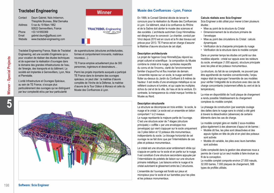
198
5
Musée des Confluences - Lyon, France
En 1999, le Conseil Général décide de lancer le concours pour la réalisation du Musée des Confluences à Lyon. Ce bâtiment, situé à la confluence du Rhône et de la Saône doit abriter le musée des sciences et des sociétés. L’architecte autrichien Coop Himmelblau est désigné pour le concevoir. Le chantier, conduit par Vinci depuis 2010 est en cours et la fin des travaux est prévue pour 2013. TE France est en charge d’assurer la Maitrise d’œuvre structure de cet objet.
Description architecturaleLe projet de l’agence Coop Himmelb(l)au répond au projet culturel et scientifique : la composition du Musée combine le cristal et le nuage, symboles respectifs du connu et de l’inconnu, clarté de l’environnement familier d’aujourd’hui et flou incertain de demain. L’ensemble repose sur un socle, le nuage semblant flotter au-dessus du Jardin du Confluent à 8 mètres de hauteur. Il est revêtu d’une enveloppe métallique où se reflètent couleurs et lumière, et qui capte les multiples échos du ciel et de la ville, de l’eau et de la verdure. En contraste, la transparence du cristal marque l’entrée du Musée au Nord.
Description structurelleLa structure se décompose en trois entités : le socle, le nuage et le cristal. Le socle est un ensemble en béton comportant 1 à 2 niveaux.Le nuage représente la majeure partie de l’ouvrage. C’est une structure acier de 7 étages (structure principale) « coiffée » par une enveloppe inox (enveloppe) qui vient s’appuyer sur le socle uniquement via 3 piles béton et 12 poteaux dits monumentaux, indépendants du socle. Le blocage horizontal de cet ouvrage ne se fait donc que par l’intermédiaire de ces piles et poteaux monumentaux.
Le cristal est une structure acier entièrement vitrée qui s’appuie en partie sur le socle et en partie sur le nuage. Il est constitué d’une structure secondaire appuyée par l’intermédiaire de potelets de liaison sur une structure primaire métallique. Les liaisons entre le nuage et le cristal autorisent le glissement entre les 2 structures.
L’ensemble de l’ouvrage est fondé sur pieux et micropieux pour le socle et sur barrettes pour les piles et les poteaux monumentaux.
Calculs réalisés avec Scia EngineerScia Engineer a été utilisé pour mener à bien plusieurs études :• Mise au point de la structure du Cristal • Dimensionnement de la structure primaire de
l’enveloppe • Mise au point des circulations du Cristal : calculs
dynamiques• Vérification de la charpente principale du nuage• Vérification de la structure dans le modèle complet
Dans un premier temps les études ont porté sur des modèles séparés : cristal sur appuis avec les raideurs du socle, enveloppe (1.000 appuis), structure principale avec les piles et les poteaux monumentaux.
La structure, du fait de sa complexité, ne pouvant pas être appréhendé de manière conventionnelle, l’enjeu majeur était de regrouper l’ensemble de ces modèles pour vérifier l’intégralité de la structure avec des cas de charge concomitants (notamment effets du vent et de la température).
La mise en disponibilité de l’outil plaque de chargement a rendu possible l’établissement du chargement complexe du modèle complet.
Le phasage de construction (par exemple coulage des dalles dans le nuage sans le cristal) a été géré à travers la désactivation (absences) de certains éléments dans les cas de charge.
Le modèle complet gère en réalité 2 sous-modèles grâce également à des absences d’appui et de barres :• Modèle dit fixe, les piles sont désactivées et des
appuis rigides en tête de pile et en pied des poteaux sont activés
• Modèle dit variable, les piles avec leurs barrettes sont activées
Cette complexité dans la gestion des absences nous a permis de n’avoir qu’un seul modèle à faire évoluer au fil de la conception.Le modèle complet comporte environ 27.000 nœuds, 32.000 barres, 7.000 plaques de chargement, 588 types de profilés utilisés.
Tractebel Engineering France, filiale de Tractebel Engineering, est une société d’ingénierie qui a pour vocation de réaliser des études techniques et de superviser la réalisation d’ouvrages dans le domaine des grandes infrastructures de l’eau, de l’énergie, des transports et du bâtiment. La société est implantée à Gennevilliers, Lyon, Nice et Pierrelatte.
L’unité Infrastructure et Ouvrages Spéciaux, au sein de TE France, s’occupe plus particulièrement des ouvrages qui se distinguent par leur complexité et/ou par leur particularité
de superstructures (structures architecturales, formes et comportement innovants, matériaux nouveaux…).
TE France emploie actuellement plus de 300 personnes, ingénieurs et dessinateurs…
Parmi les projets importants auxquels a participé TE France dans le domaine des ouvrages spéciaux, on peut citer : la maitrise d’œuvre complète de l’Arche de la Défense, la maitrise d’œuvre de la Tour Odéon à Monaco et celle du Musée des Confluences à Lyon.
Tractebel EngineeringContact Daum Gabriel, Naïs Imbernon,
Théophile Bruneau, Bilal DernaikaAddress 5 rue du 19 Mars 1962 92622 Gennevilliers, FrancePhone +33 141850369Email [email protected] www.tractebel-engineering.com
Software: Scia Engineer
Tractebel Engineering . . . . . . . . . . . . . . . . . . . . . . . . . . . . . . . . . The Confluences Museum - Lyon, France
Win
ner -
Spe
cial P
rojec
tsWinner

199
Project information
Short project description
Nemetschek Engineering User Contest 2011 - Category 5: Special Projects
5
Win
ner -
Spe
cial P
rojec
ts
The Confluences Museum is located on an exceptional site at the junction of 2 rivers. From this particular scenery, architects have imagined two complexly connected architectural units. The first one, the crystal, is a steel and glass entrance structure. This rising crystal connects to the second unit, the cloud. The cloud is also a steel structure, which leans only on three major concrete supports, named “piles” and 12 concrete columns. Moreover, in contrast with the crystal, the cloud is covered by a stainless metal cladding. These two units are positioned on a structurally independent, two-storeyed building in reinforced concrete.
Owner Département du RhôneArchitect Coop HimmelblauGeneral Contractor VinciEngineering Office Tractebel Engineering FranceConstruction Period From July 2010 to July 2013Location Lyon, France
The Confluences MuseumLyon, France
Tractebel Engineering . . . . . . . . . . . . . . . . . . . . . . . . . . . . . . . . . The Confluences Museum - Lyon, France
Quote of the Jury
“This very original structure with an extreme complicated shape is technically very challenging as no element has the same geometry: a concrete foundation with huge columns support the steel cloud and the crystal structure. Different materials, with dynamic calculations and difficult foundation conditions, make this project very demanding. A perfect presentation gave the finishing touch.”
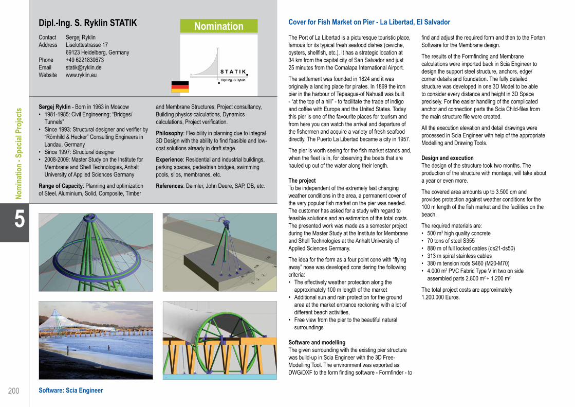
200
5
Dipl.-Ing. S. Ryklin STATIK . . . . . . . . . . . . . . . . . . . . . . . . . . . . . Cover for Fish Market on Pier - La Libertad, El Salvador
Dipl.-Ing. S. Ryklin STATIKContact Sergej RyklinAddress Liselottestrasse 17 69123 Heidelberg, GermanyPhone +49 6221830673Email [email protected] www.ryklin.eu
Cover for Fish Market on Pier - La Libertad, El Salvador
The Port of La Libertad is a picturesque touristic place, famous for its typical fresh seafood dishes (ceviche, oysters, shellfish, etc.). It has a strategic location at 34 km from the capital city of San Salvador and just 25 minutes from the Comalapa International Airport.
The settlement was founded in 1824 and it was originally a landing place for pirates. In 1869 the iron pier in the harbour of Tepeagua-of Nahuatl was built - “at the top of a hill” - to facilitate the trade of indigo and coffee with Europe and the United States. Today this pier is one of the favourite places for tourism and from here you can watch the arrival and departure of the fishermen and acquire a variety of fresh seafood directly. The Puerto La Libertad became a city in 1957.
The pier is worth seeing for the fish market stands and, when the fleet is in, for observing the boats that are hauled up out of the water along their length.
The projectTo be independent of the extremely fast changing weather conditions in the area, a permanent cover of the very popular fish market on the pier was needed. The customer has asked for a study with regard to feasible solutions and an estimation of the total costs. The presented work was made as a semester project during the Master Study at the Institute for Membrane and Shell Technologies at the Anhalt University of Applied Sciences Germany.
The idea for the form as a four point cone with “flying away” nose was developed considering the following criteria:• The effectively weather protection along the
approximately 100 m length of the market • Additional sun and rain protection for the ground
area at the market entrance reckoning with a lot of different beach activities,
• Free view from the pier to the beautiful natural surroundings
Software and modellingThe given surrounding with the existing pier structure was build-up in Scia Engineer with the 3D Free-Modelling Tool. The environment was exported as DWG/DXF to the form finding software - Formfinder - to
find and adjust the required form and then to the Forten Software for the Membrane design.
The results of the Formfinding and Membrane calculations were imported back in Scia Engineer to design the support steel structure, anchors, edge/corner details and foundation. The fully detailed structure was developed in one 3D Model to be able to consider every distance and height in 3D Space precisely. For the easier handling of the complicated anchor and connection parts the Scia Child-files from the main structure file were created.
All the execution elevation and detail drawings were processed in Scia Engineer with help of the appropriate Modelling and Drawing Tools.
Design and executionThe design of the structure took two months. The production of the structure with montage, will take about a year or even more.
The covered area amounts up to 3.500 qm and provides protection against weather conditions for the 100 m length of the fish market and the facilities on the beach.
The required materials are: • 500 m3 high quality concrete• 70 tons of steel S355• 880 m of full locked cables (ds21-ds50)• 313 m spiral stainless cables• 380 m tension rods S460 (M20-M70)• 4.000 m2 PVC Fabric Type V in two on side
assembled parts 2.800 m2 + 1.200 m2
The total project costs are approximately 1.200.000 Euros.
Sergej Ryklin - Born in 1963 in Moscow• 1981-1985: Civil Engineering; “Bridges/
Tunnels”• Since 1993: Structural designer and verifier by
“Römhild & Hecker” Consulting Engineers in Landau, Germany
• Since 1997: Structural designer• 2008-2009: Master Study on the Institute for
Membrane and Shell Technologies, Anhalt University of Applied Sciences Germany
Range of Capacity: Planning and optimization of Steel, Aluminium, Solid, Composite, Timber
and Membrane Structures, Project consultancy, Building physics calculations, Dynamics calculations, Project verification.
Philosophy: Flexibility in planning due to integral 3D Design with the ability to find feasible and low-cost solutions already in draft stage.
Experience: Residential and industrial buildings, parking spaces, pedestrian bridges, swimming pools, silos, membranes, etc.
References: Daimler, John Deere, SAP, DB, etc.
Software: Scia Engineer
Nomi
natio
n - S
pecia
l Pro
jects
Nomination

201
Project information
Short project description
Nemetschek Engineering User Contest 2011 - Category 5: Special Projects
5
Nomi
natio
n - S
pecia
l Pro
jects
Dipl.-Ing. S. Ryklin STATIK . . . . . . . . . . . . . . . . . . . . . . . . . . . . . Cover for Fish Market on Pier - La Libertad, El Salvador
Cover for Fish Market on PierLa Libertad, El Salvador
Owner Departament La Libertad, El SalvadorArchitect Dipl.-Ing. S. Ryklin, Master Membrane Structures, Archineer M.St.General Contractor Design StageEngineering Office Dipl.-Ing. S. Ryklin STATIKConstruction Period From January 2009 to ...Location Port La Libertad, El Salvador
This project is about the cover of the popular fish market on the Pier in La Libertad in El Salvador. A permanent roof was necessary because of the extremely fast changing weather conditions in that area.The idea for the form as a four point cone with a “flying away” nose was developed considering the following criteria: the effectively weather protection along the approximately 100m length of the market, additional sun and rain protection for the ground area at the market entrance reckoning with a lot of different beach activities and the free view from the pier to the beautiful natural surroundings had to be kept.

202
5
Software: Scia Engineer
Setec BâtimentContact Victoire Saby, Carlos NoumedemAddress Tour Gamma D 58 quai de la Rapée 75583 Paris, FrancePhone +33 1 40 04 63 04Email [email protected] www.batiment.setec.fr
Canopée du Centre Culturel - Mascate, Oman
Présentation du projetLe ministère de l’héritage et de la culture avait pour ambition de construire à Mascate un grand centre culturel, véritable pôle urbain pour la ville. Architecture Studio a ainsi proposé un projet composé de plusieurs grands ensembles de bâtiments regroupés sous une fine couverture perforée : la canopée.
Une spécificité et un grand challenge du projet est cette immense canopée perforée de 40.000 m² qui se courbe, se déforme, en fonction de la géométrie et de la hauteur des bâtiments qu’elle abrite.
La mission de Setec Bâtiment a consisté, dans un premier temps, à la conception de la canopée en équipe avec les architectes. De nombreuses solutions technologiques ont ainsi été proposées, puis étudiées à l’aide de Scia Engineer : panneaux en ductal, coque en béton, structure métallique avec parements GRC. Une fois les grands principes de construction adoptés, Setec Bâtiment a étudié finement l’ensemble de la structure et dimensionné les différents éléments.
Les bâtiments sur lequel reposent la canopée et notamment le théâtre ont aussi fait l’objet de calculs détaillés.
Une géométrie complexe facilement modéliséeLa canopée présente une géométrie très irrégulière : son altimétrie varie ainsi entre 13 m en périphérie et 35 m en haut du théâtre. Elle repose sur une trame de poteaux de 5 m x 5 m. La couverture présente ainsi une grande partie de zones courbes, en simple ou double courbures. Le choix d’une grille de poutres acier courbes ou droite selon les endroits a finalement été adopté pour la structure primaire. La géométrie initiale a été rationalisée en utilisant le plugin de Rhinocéros : Grasshopper de façon à faciliter la fabrication des poutres et en réduire ainsi le coût. La charpente métallique est ensuite recouverte d’un complexe bac acier, béton, étanchéité qui assure le contreventement de la canopée dans son plan. Celle-ci est régulièrement traversée par des lanterneaux assurant ainsi l’arrivée de lumière naturelle sous la canopée.
Les différents modèles 3D ont été réalisés en important dans Scia Engineer les différents calques du fichier 3D. Les éléments de structure : barres, lignes ou macro2d
sont alors générés. Il est ensuite extrêmement aisé d’appliquer sections, matériaux ou charges à chacun des éléments.
Une analyse dynamique/sismiqueLe comportement dynamique de la canopée à été étudié. Le modèle 3D complet ‘canopée et bâtiment’ a permis de mettre en exergue le phénomène dit ‘coup de fouet’ subi par la canopée. En effet, la différence de rigidité entre les bâtiments en béton et la canopée en charpente métallique crée en phénomène d’amplification des efforts sismiques. L’analyse dynamique a également permis de se confronter au contreventement de la canopée. En plus de l’irrégularité verticale observée, il y a une irrégularité horizontale due à la position des contreventements sous la canopée. La canopée repose sur des poteaux très élancées allant jusqu’à 25 m de haut pour 30 cm de diamètre, et se comporte donc par endroit comme un ensemble relativement souple dont les déplacements sont difficiles à limiter.
La flexibilité de Scia EngineerScia Engineer constitue une interface flexible qui a facilité notre modélisation sur différents points. En effet il nous a été possible de travailler à plusieurs ingénieurs sur le projet et de regrouper ensuite nos modèles dans le même fichier Scia Engineer (un modélisant les bâtiments, l’autre la canopée).
D’autre part, l’importation depuis des fichiers dwg de la géométrie complète en tant que barre ou coque nous a permis de gagner énormément en temps et en précision.
Enfin, pour nous adapter aux normes utilisées par les entreprises réalisant in fine le projet à Oman, nous avons du travailler avec la norme américaine AISC LRFD pour la charpente métallique, le British Standard pour le béton et l’UBC pour le séisme. Scia Engineer nous as permis de passer rapidement et facilement d’une norme à l’autre.
Le groupe SETEC : l’assurance d’un grand groupe - Setec Bâtiment est la filiale du groupe SETEC spécialisée dans l’Ingénierie du bâtiment. Créé en 1957, le groupe SETEC représente aujourd’hui l’une des toutes premières sociétés d’Ingénierie françaises d’envergure internationale, avec plus de 1.700 collaborateurs répartis au sein de 25 filiales, pour un chiffre d’affaire de plus de 188 millions d’Euros.
Setec Bâtiment : multidisciplinaire et innovant - Setec Bâtiment, qui compte environ 230 collaborateurs, dispose de compétences
techniques fortes dans tous les domaines du bâtiment : de la structure, à la conception environnementale. Une intense collaboration dès le début des projets entre les différents services techniques en interne et aussi avec les acteurs extérieurs permettent la naissance de solutions intégrées et innovantes.
Setec Bâtiment a récemment crée Praxice qui regroupe dans un pôle unique les équipes de conceptions environnementales et celles de l’ingénierie de la maintenance et de l’exploitation.
Setec Bâtiment . . . . . . . . . . . . . . . . . . . . . . . . . . . . . . . . . . . . . . Canopy of Cultural Complex - Mascate, Oman
Nomi
natio
n - S
pecia
l Pro
jects
Nomination

203
Project information
Short project description
Nemetschek Engineering User Contest 2011 - Category 5: Special Projects
5
Nomi
natio
n - S
pecia
l Pro
jects
Owner Ministère de la Culture du Sultanat d’OmanArchitect Architecture StudioEngineering Office Setec BâtimentConstruction Period From January 2012 to January 2014Location Mascate, Oman
The project is composed of 15 independent buildings, among them: the national theatre, the national library, the national archives, and other facilities. Everything is gathered under a slender perforated shell: the canopy. The main characteristic of this project is the huge perforated canopy of 40 000 m² which curves and deforms depending on the geometry and the height of the building it covers. The main challenges were the design and the calculation of the canopy in a seismic zone as well as the theatre with its free form and heavy technical equipment, all according to a variety of national standards.
Canopy of Cultural ComplexMascate, Oman
Setec Bâtiment . . . . . . . . . . . . . . . . . . . . . . . . . . . . . . . . . . . . . . Canopy of Cultural Complex - Mascate, Oman

204
5
U2 Stage - 360° Tour - Around the World
Project data• Height main structure: +/- 28 m• Height pylon: +/- 51 m• Width: +/- 60 m• Depth: +/- 44 m• Global capacity stage: 175 ton of sound, light and
video equipment• Mass: +/- 310 ton, 38 trailers / set (3 complete
identical sets are built)• Name of Project: U2 - 360°• Production Manager: Jake Berry• Architect: Mark Fisher• Technical coordinator: Jeremy Lloyd• Project manager: Dirk Dedecker (Stageco)• Production manager fabrication: Bert Kustermans
(Stageco)• Engineer steel structure: Tom Frederickx (Stageco)• Design steel structure: Koen Peeters en Gert
Hulsmans (Stageco)• Set production: TAIT (US)• LED video system: Barco and XL video (Belgium)• Location: mobile structure; trucked, shipped and
flown around the World (90 cities in 2 years)• Building sequence: 4 days building up, 1 production
day, 1 show day, 2 days taking down and loading, 1 or 2 travel days
DescriptionThe story of how the stage made its journey from concept to completion is remarkable. It required the vision of the artists themselves, the inspiration of renowned stage and set designer Mark Fisher and his team at Stufish, the logistical and touring expertise of the show’s internationally respected production manager Jake Berry and the innovativeness of Stageco, who adapted heavy civil engineering techniques to the entertainment world in a way that has never been achieved before.
The design all started life as a simple crayon and paper sketch by Mark Fisher inspired by the iconic design of the famous Theme Building restaurant at Los Angeles International Airport (LAX). The concept evolved through discussions between Fisher and Stageco, reflecting the aspirations of U2, who wanted the show to be as inclusive as possible for fans.
In October 2008 U2 “pressed go” on the 360º tour project and Stageco was asked to start work on detailed structural calculations, including a practical modular design which would allow the system to be toured.
Stageco appointed a skilled in-house team with the experience and expertise required to deliver the project, that worked with outside agencies where necessary.
Stageco devised a way of constructing the structure on site which allowed the production to access many more stadia than would have been possible through traditional methods. In the initial phase of the build, the central 80 ton octagon structure which carries the lighting, sound and screens needed to be lifted using three 60 ton cranes. It was suspended on a standard Stageco truss while the four main lifting portals - twin towers positioned either side of each leg - were installed. The use of these portals (made up of the company’s existing tower system and often used as stages in their own right) allowed Stageco to bypass two particular issues associated with a more traditional technique. The giant cranes they would otherwise have had to use could not have fitted into most stadia. More seriously, they would not have been able to lift the stage with the precision required as any unexpected shift in the balance of this huge weight would have potentially drastic consequences. The “twin tower” portal system allowed Stageco to gradually raise the Octagon to full height, connecting additional segments of the leg as it lifted.One vital extra element was required to make the system feasible. To ensure the portals lifted the structure with the exact precision necessary, Stageco engaged a new partner, Madrid-based hydraulics specialists Enerpac, to develop specialist software-driven hydraulics which would allow the lift to be correctly synchronised.
Once the structure was fully in place and secured, the “twin towers” were dismantled and removed leaving in place the 100% bespoke structure which is all the public will ever see. At the end of every show on the U2 tour, Stageco’s logistical ingenuity will come back into play for the de-rig, when the towers are re-installed, the legs dismantled and the “octagon” lowered slowly back to the ground in a perfectly synchronised manner.
Stageco is a widely acclaimed international staging, event engineering and structures innovator. During recent years Stageco has been best known for supplying stunning stages for international tours including The Rolling Stones, U2, etc. and festival stages including V Festival, Rock Werchter Festival (in Stageco’s hometown), etc.Stageco also provides a wide range of innovative indoor and outdoor staging solutions to corporate, sporting and broadcast events, capitalizing on over two decades of expertise gained in the entertainment sector.
We love to be challenged to create powerful event engineering, which is the case when working with the leading event designers. Our application of best practice when it comes to health and safety is pivotal to the success of any event. That is why Stageco designs and fabricates stages that exceed international licensing standards and supplies trained crew to ensure that the best working practices are employed on our structures.
StagecoContact Tom FrederickxAddress Kapelleweg 6 3150 Tildonk, BelgiumPhone +32 16 608471Email [email protected] www.stageco.com
Software: Scia Engineer
Stageco . . . . . . . . . . . . . . . . . . . . . . . . . . . . . . . . . . . . . . . . . . . . U2 Stage - 360° Tour - Around the World
Nomi
natio
n - S
pecia
l Pro
jects
Nomination

205
Project information
Short project description
Nemetschek Engineering User Contest 2011 - Category 5: Special Projects
5
Nomi
natio
n - S
pecia
l Pro
jectsThis project is about one of the largest stages ever toured in any field of entertainment. The structure’s
central grid is raised 28 metres high, with legs traversing the width of a soccer pitch and a central antenna reaching as high as 51 metres. The steel structure weighs 220 tons, excluding both the 90 tons of steel ballast that travels with each system and the rigging loads. Stageco has produced three identical systems for the band’s world tour, each one taking a specialist Stageco team five days to erect and another two days to dismantle, before being packed onto 38 trucks for transportation to the next venue.
Owner Live NationArchitect Mark FisherGeneral Contractor Live NationEngineering Office Stageco BelgiumConstruction Period Touring from June 2009 to July 2011Location All over the world
U2 Stage - 360° Tour Around the World
Stageco . . . . . . . . . . . . . . . . . . . . . . . . . . . . . . . . . . . . . . . . . . . . U2 Stage - 360° Tour - Around the World

206
5
Cate
gory
5: S
pecia
l Pro
jects
AECOM . . . . . . . . . . . . . . . . . . . . . . . . . . . . . . . . . . . . . . . . . . . . Spartak Moscow Stadium - Moscow, Russian Federation
AECOMContact Thomas Webster, Andy CowardAddress 63-77 Victoria Street AL1 3ER St Albans, United KingdomPhone +44 1727535000Email [email protected] www.aecom.com
Spartak Moscow Stadium - Moscow, Russian Federation
Spartak Moscow is one of the most high profile clubs in the Russian Federation and they regularly qualify for the UEFA Champions League. However, Spartak Moscow Football Club has never owned their own stadium and has always shared facilities with other teams. AECOM has been appointed to design and manage the delivery of a brand-new 45.000 seat stadium to provide a state of the art venue for Spartak Moscow that meets FIFA World Cup stadium standards, forming part of the Russian 2018 World Cup bid. A pan-European AECOM team, comprising stadium design specialists in the UK and local Russian engineers and architects, has been collaborating to provide a fantastic new home for the team.
Key structural design features• Uninterrupted spectator views with seating in close
proximity to the pitch• High Snow and Ice Loading• Designed for a temperature range of -40ºC to +40ºC • Vibration analysis for Human Structure Interaction• Design to allow for multiple support removal
FoundationsRotary bored piled foundations are necessary to suit the ground conditions. A range of diameters have been adopted to provide the most economical solution. These will be drilled to a depth of between 33 m and 43 m below existing site level.
Concrete grandstandsThe stadium grandstands have been designed using insitu reinforced concrete frames with precast concrete seating units. The structural frames are on a consistent 7.6 m grid which allows for maximum repetition of the concrete frame and precast. The insitu frames provide a robust solution with continuous ties between structural members. Scia Engineer non-linear analysis was used to investigate the effects of sudden column removal, satisfying a key counter-terrorism requirement.
The concrete structure is divided into 12 segments, each separated by a movement joint. Thermal effects were modelled in Scia Engineer to predict the change in geometry and minimise the build up of thermal stress. Each of the 12 segments has its own stability system
allowing them to act independently.The human structure interaction was assessed by extracting the mode shapes and modal masses from Scia Engineer using Total Commander. The results of these elements where then analysed using guidance produced by the Institute of Structural Engineers (IStructE) joint working group entitled, “Dynamic performance requirements for permanent grandstands subject to crowd action”.
Steel roofThe primary roof structure consists of an arrangement of four trusses, with two sets of parallel steel trusses intersecting above the corners of the pitch. This allows the very high design snow load on the roof to be taken to eight points of support and prevents collapse by the redistribution of the load if a support is ever removed. The longer trusses span 217 m along the length of the pitch and the shorter perpendicular trusses span approximately 180 m. A secondary roof structure then spans from the concrete columns at the back of the grandstands to the primary trusses spanning across the stadium. The complete roof structure was modelled in Scia Engineer to minimise structure self-weight and analyse the complicated geometry.
For stability, the roof must act as a continuous diaphragm. Thermal stresses are dissipated by allowing the roof to ‘breath’ which has been achieved by having one restrained bearing on each side of the stadium to take horizontal forces and bi-directional bearings on all other supports. The anticipated movement have been calculated and assessed using Scia. The anticipated movement is 150 mm at each support.
The natural frequency of the stadium roof was assessed using Scia Engineer, with the conclusion that there is little risk of dynamic roof excitation from wind load.
The complex geometry of the roof was translated into Autodesk REVIT from Scia Engineer using the REVIT- Scia Engineer Link.
AECOM is a global provider of professional, technical and management support services to a broad range of construction and infrastructure markets.
With approximately 51.000 employees around the world, AECOM is a leader in all of the key markets that it serves, providing a blend of global reach, local knowledge, innovation and technical excellence in delivering solutions that enhance and sustain the world’s built, natural, and social environments.
From major road and rail projects to energy generation, water management systems and creating beautiful and successful buildings and places, AECOM in Europe works closely with clients across all areas of the built and natural environment.
Our teams of award-winning engineers, designers, planners and project managers ensure that our solutions outperform convention. Combining global resources with local expertise provides exceptional, high-quality, cost-effective professional and technical solutions.
Software: Scia Engineer

207
Project information
Short project description
Nemetschek Engineering User Contest 2011 - Category 5: Special Projects
Cate
gory
5: S
pecia
l Pro
jects
5
AECOM . . . . . . . . . . . . . . . . . . . . . . . . . . . . . . . . . . . . . . . . . . . . Spartak Moscow Stadium - Moscow, Russian Federation
Spartak Moscow StadiumMoscow, Russian Federation
Owner Spartak Moscow Football ClubArchitect AECOM MoscowEngineering Office AECOM LondonConstruction Period From September 2010 to December 2013Location Moscow, Russian Federation
This project is about the design and construction of a new stadium for the Spartak Moscow Football Club. Up to now, Spartak Moscow Football Club has never owned their own stadium and has always shared facilities with other teams. AECOM has been appointed to design and manage the delivery of a brand-new 45.000 seat stadium to provide a state of the art venue for Spartak Moscow that meets FIFA World Cup stadium standards and that is intended for the Russian 2018 World Cup. The stadium has been designed to overcome large temperature variations and very high snow and ice loads.

208
5
Cate
gory
5: S
pecia
l Pro
jects
Software: Scia Engineer
AE&E Austria Gmbh&Co KG . . . . . . . . . . . . . . . . . . . . . . . . . . . . Renovation of a Steel Silo - Austria
AE&E Austria Gmbh&Co KGContact Siegfried WallnerAddress Waagner-Biro-Platz 1 8074 Raaba, AustriaPhone +43 316 501 2796Email [email protected] www.aee.co.at
Renovierung eines Stahlsilos, Österreich
Für die Berechnung und Ausführung von Stahlsilokonstruktionen sind seit 2007 bzw. 2008 neue europäische Normen gültig:• EN 1991-4 (2007) Einwirkungen auf Tragwerke. Teil
4 - Einwirkungen auf Silos und Flüssigkeitsbehälter.• EN 1993-4-1 (2008). Bemessung und Konstruktion
von Stahlbauten. Teil 4-1: Silos.• EN 1993-1-6 (2007): Bemessung und Konstruktion
von Stahlbauten. Teil 1-6: Festigkeit und Stabilität von Schalen.
Neu bei diesen Normen ist nun die Berücksichtigung der Silogröße und besonderer Randbedingungen wie Auflagerung auf Einzelstützen oder exzentrische Entleerung hinsichtlich der Tiefe der Belastungsannahmen bzw. des Mindestberechnungsaufwandes. Dies hat zur Folge, daß nun eine zeitgemäße numerische Berechnung (Finite-Elemente-Methode) außer bei kleineren Silos normativ verpflichtend ist.
Gegenüber ihrer Vorgängernorm (z.B. DIN 1055 Teil 6 (1987)) zeigt die Lastnorm EN 1991-4 einige doch gravierende Änderungen bzw. Ergänzungen. Wesentlich geändert sind nun die Lastansätze für Silos mit großen Entleer- aber auch Füllexzentrizitäten. Die Erhöhung der rotationssymmetrischen Silolasten basierend auf der Silotheorie nach Janssen ist nicht mehr ausreichend. Es sind nun bei Silos mit kreisförmigem Querschnitt ungleichförmige also nicht rotationssymmetrische Radialdrücke bzw. Wandreibungslasten in der Berechnung zu berücksichtigen. Dieser Belastungstyp wird als Fließkanalbelastung bezeichnet. Es sind dabei 3 unterschiedliche Belastungskonfigurationen die im Wesentlichen durch den Fließkanalradius gesteuert werden zu untersuchen. Grundlegenden Arbeiten dazu stammen von Prof. Rotter aus Edinburgh (UK).
Die Relevanz der neuen Regelungen wird anhand eines Schadensfalles an einem diskret gelagerten Schraubsilo mit großer Entleerexzentrizität dargestellt.Dabei wurden zur Begutachtung und zur Festlegung der Reparaturmaßnahmen Berechnungen mittels Scia Engineer Release 2008 durchgeführt.
Der Silo mit einem Nutzvolumen von 620 m3 hat einen Radius von 3.50 m, eine Höhe des zylindrischen
Schaftes von 16.10 m und eine Trichterhöhe von 5.00 m. Das Silofüllgut ist Wettersteinkalk mit rechnerischer Wichte von 18 kN/m3.
Als Besonderheit ist hier zu erwähnen, daß der Silo neben dem zentrischen Auslauftrichter noch eine exzentrische Zusatzentleerung aufweist. Diese wurde aus betrieblichen Gründen planmäßig genutzt.
Das Schadensbild zeigte eine globale Verformung des Silomantels mit einer lokalen Beule im oberen Siloschaftdrittel.
Die Berechnungen mittels Scia Engineer belegten eindeutig den vermuteten Zusammenhang von exzentrischer Entleerung mit der Ausbildung eines Fließkanals im Siloschüttgut. Das vorhandenen Verformungsbild bzw. der eingetretene Beulschaden konnten rechnerisch eindeutig belegt werden.
Es zeigte sich überdies, daß der Silo auch hinsichtlich der „alten“ Belastungsvorschriften nach DIN 1055 Teil 6 (1987) nicht ausreichend dimensioniert war. Die Originalstatik des Silolieferanten basierte auf unzureichenden einfachen Berechnungsmodellen, welche die Lastabtragung der Vertikallasten über den Einzelstützen nicht wiedergeben konnten.
Die Sanierung des Silos erfolgte einerseits durch Erhöhung der Silowandstärken im Schaftbereich und andererseits durch Anordnung von Ringsteifen.
Die Erhöhung der Wanddicken erfolgte durch den Austausch der unteren beiden Schaftschüsse gegen dickwandigere (12 mm statt 10 mm), der mittlere Schaft wurde weiter verwendet (10 bis 6 mm Wandstärke), der obere Schaft (6 und 5 mm Wanddicke) wurde nicht weiter verwendet. Der verbleibende oberste Schaftschuß (5 mm), welcher mit dem Silodach verschweißt ist, wurde lokal versteift.
Für die Abtragung der Fließkanalbelastung wurden 4 Ringe angeschweißt (U200).
Für die Durchführung der Sanierung war die geschraubte Ausführung des Silos von Vorteil.
AE&E Austria Gmbh & Co KG ist ein österreichisches Unternehmen mit Standort Raaba bei Graz. Die Firma geht auf eine Vereinigung der traditionsreichen Anlagenbaufirmen Waagner-Biro und Simmering-Graz-Pauker im Jahr 1992 zurück. Die Gründung der Vorgängerfirmen datiert mit dem Jahr 1854.
Die Hauptunternehmensfelder liegen im Bereich der Heizkraftwerke mit Biomasse, Laugen-, Gichtgas- oder Reststofffeuerung aber auch konventionell mit Kohlefeuerung und der Rauchgasreinigung.
Der folgende Projektbeitrag stammt aus der Tätigkeit des Autors beim Ingenieurbüro DI Woflgang PLATZER (A-8010 Graz, C.v.Hötzendorfstraße 68).
Dieses Projekt wurde beim “BIBERACHER STAHLBAUSEMINAR 2010” in Neu-Ulm vor 110 Zuhörern und in Wien vor 75 Zuhörern im Februar 2010 mit dem Vortragstitel “Neue Regelungen gemäß Eurocode (EN 1991-4 und EN 1993-4-1) zur Berechnung von Stahlsilos - Darstellung anhand eines Schadensfalles an einem diskret gelagerten Schraubsilo” präsentiert.

209
Project information
Short project description
Nemetschek Engineering User Contest 2011 - Category 5: Special Projects
Cate
gory
5: S
pecia
l Pro
jects
5
Renovation of a Steel SiloAustria
AE&E Austria Gmbh&Co KG . . . . . . . . . . . . . . . . . . . . . . . . . . . . Renovation of a Steel Silo - Austria
Engineering Office DI Wolfgang PLATZERConstruction Period From August 2008 to March 2009Location Austria
The project is about the renovation of a steel silo. The goods for this silo are granular and fibrous cements with a computational density of 18 kN/m3. As a special feature it has to be mentioned that the silo, besides the central discharge hopper also has an additional eccentric emptying installation. The new principles as provide by the Eurocode (EN 1991-4 and EN 1993-4-1) were used; more specifically for the structural design of steel silos.

210
5
Cate
gory
5: S
pecia
l Pro
jects
ARCADIS Nederland BVContact Meint Smith, Tom Borst (Arcadis),
Gijs Joossen (ONL), Pieter Schreurs (ONL)Address Lichtenauerlaan 100 3006AE Rotterdam, The NetherlandsPhone +31 646158726Email [email protected] www.arcadis.nl
Geluidswering Haarrijn A2 - Utrecht, Nederland
OntwerpHet ontwerp van deze 1.8 km lange en 12 m hoge geluidswering langs de A2 bij Haarrijn-Utrecht is van ONL [Oosterhuis_Lénárd]. De geluidswering beschermt de te ontwikkelen nieuwbouwwijk ‘Haarrijnseplas’ en zal samenvloeien met de bedrijven op het erachter gelegen bedrijventerrein.
Het architectonische concept bestaat uit lange elastische ‘Powerlines’ en een vlakverdeling in de boven-, midden- en onderzijde. Aan de A2-zijde wordt de constructie afgewerkt met een gevlochten RVS en aan de Haarrijn-zijde met aluminium beplating. De draagconstructie bestaat uit een ruimtelijk vakwerk van stalen buizen.
Het scherm wordt in het midden doorsneden door de Maarsenseweg. Hierdoor ontstaan twee afzonderlijke constructies van respectievelijk ca. 1.100 en 700 meter lang. In totaal zal in het scherm zo’n 760 ton staal en 21.600 m2 aluminium beplating en gevlochten RVS verwerkt worden.
BIMHet ontwerp is volledig volgens het BIM-concept opgezet. Het digitale draadmodel van de architect wordt vertaald naar XML-bestanden met staven, vlakken, knopen, scharnieren en steunpunten welke worden ingelezen in Scia Engineer.
Met behulp van het Scia Engineer model worden de profielen geoptimaliseerd en deze gegevens worden weer digitaal teruggekoppeld naar het architectonische model.
Met de roundtrip module wordt het rekenmodel geëxporteerd naar Revit Structure om hiermee de constructieve tekeningen te maken.
In de werkfase zullen ook alle benodigde gegevens uit de modellen digitaal aan de staalleverancier worden aangeleverd in het format dat benodigd is voor de machines (file to factory - CNC-productie). Hierdoor is er geen repetitie nodig en ontstaat maximale vrijheid voor de ontwerpers om de geometrie aan te passen en de constructie te optimaliseren, terwijl de faalkosten geminimaliseerd worden.
ModellenHet model van het zuidelijke deel van het scherm (1.100 meter lang) is het grootst met ca. 6.000 knopen, bijna 25.000 staven en iets meer dan 10.000 platen. Het andere deelmodel is van dezelfde ordegrootte. De platen werken constructief niet mee, maar dienen als belastingspanelen. Omdat elk paneel van het scherm net een andere oriëntatie heeft wordt de lastengenerator gebruikt om de windbelasting op de draagconstructie te genereren.
OptimalisatieIn eerste instantie is een variantenstudie uitgevoerd met een deelmodel van een representatief segment van ca. 100 strekkende meter scherm. Hiermee is de geometrie geoptimaliseerd voor materiaalgebruik en bouwkosten. Enerzijds is de optimale gridmaat en profielkeuze van het ruimtelijk vakwerk bepaald en anderzijds is de optimale funderingbreedte en het optimale funderingssysteem bepaald.Daarna zijn de complete modellen gebruikt om de profielen te optimaliseren, de paalkrachten te bepalen en de uitbuiging te controleren.
Overhangende puntenEen van de uitdagingen zijn de overhangende punten van het scherm ter plaatse van het kruisende viaduct van de Maarsenseweg. Deze punten volgen het talud van het viaduct en kragen ca. 36 meter uit ten opzichte van de fundering. Hier worden een relatief stijve fundering, relatief zware profielen en aangepaste knoopverbindingen toegepast om de constructie voldoende stijfheid te geven.
ConclusieMet behulp van Scia Engineer was ARCADIS in staat om in zeer nauwe samenwerking met architect ONL binnen gestelde randvoorwaarden een uitdagende, maar optimale constructie te ontwerpen, waarbij beide partijen kunnen profiteren van een maximale vrijheid in het ontwerpproces en de opdrachtgever de bouwkosten geminimaliseerd weet.
ARCADIS is een toonaangevende, wereldwijd actieve, kennisgedreven onderneming. Wij leveren design-, advies- en ingenieursdiensten aan bedrijven in binnen- en buitenland. Het succes van de klant staat voorop in onze aanpak. We realiseren projecten en programma’s vanaf het concept en ontwerp tot de oplevering en het beheer. ARCADIS is actief op de gebieden van Gebouwen, Milieu & Ruimte, Mobiliteit, Water
Het is onze ambitie om aansprekende bouwwerken te ontwerpen waarbij de draagconstructies tevens een wezenlijke bijdrage
leveren aan het architectonische beeld.
Wij ondersteunen het creatieve proces van de architect vanaf de start van het project met haalbare technische oplossingen.
Mede ondersteund door een vergaand gebruik van BIM-modellen realiseren wij integrale ontwerpen die tot stand komen door intensieve samenwerking en een open communicatie tussen verschillende adviseurs.
ARCADIS Nederland BV . . . . . . . . . . . . . . . . . . . . . . . . . . . . . . . Sound Barrier Haarrijn A2 - Utrecht, The Netherlands
Software: Scia Engineer

211
Project information
Short project description
Nemetschek Engineering User Contest 2011 - Category 5: Special Projects
Cate
gory
5: S
pecia
l Pro
jects
5
Owner Gemeente UtrechtArchitect ONL [Oosterhuis_Lénárd]Engineering Office ARCADIS Nederland BVConstruction Period From 2011 to ...Location A2 Haarrijn, Utrecht, The Netherlands
This project is about the structural design of a sound barrier along highway A2 near Utrecht. The 1.8 km long and 12 m high structure consists of a space frame of steel tubes. Because the BIM concept was adopted from architectural design via structural design to steel production (file to factory) repetition of elements is not necessary which gives maximum freedom of design and optimisation. The entire structure was imported in Scia Engineer using XML. The geometry was optimized for construction costs and designed for strength, stability and stiffness. This provides our client as well as the public with an exciting structure at minimum costs.
Sound Barrier Haarrijn A2Utrecht, The Netherlands
ARCADIS Nederland BV . . . . . . . . . . . . . . . . . . . . . . . . . . . . . . . Sound Barrier Haarrijn A2 - Utrecht, The Netherlands

212
5
Cate
gory
5: S
pecia
l Pro
jects
Software: Scia Engineer
Multifunctional Offshore Crane - Vlissingen, The Netherlands
The project regards a multifunctional offshore crane which loads up to 1.500 metric tons in combination with the 63 meter double main boom.
IntroductionB.V. Ingenieursbureau M.U.C., situated in Terheijden, received from contractor Zwagerman International B.V. the order to calculate different structures for a multifunctional offshore crane.
The project concerns a base structure on which the components of the crane are fitted and the upper structure such as the A-frame, boom, and hoisting hooks. The crane can be set-up in many different boom configurations. This gives the crane an advantage because it is able to carry out different tasks. The whole machine is made of standard S355J2+N steel, except the main boom which is made of steel grade X70. The crane can be placed on a barge or work ship.
There are three different possibilities to make the base setup for the crane, these are:• The crane is equipped with 450 metric tons
counterweight which can revolve 360º
• It can be equipped with a ringer to increase the working range of the machine
• The crane can be fixed to the barge or work ship with shoring, in these situations the crane acts as a pontoon derrick
CalculationsThe calculations which are made are: the main frame, the A-frame, the main boom, the hoisting hooks.
Overall descriptionIn the figures the model is shown, you see the complete structure assembly of the mainframe, boom and hoisting hook. The main structure consists of steel plates welded together; because the plates have great thickness special weld procedure must be applied.
The main boom is made from steel tubes with a maximum diameter of 406.4 mm; the tubes are joint together by welding. Every section of the boom has couplings on the outer ends so sections can be joint together with special M52 blots. With this system, various configurations can be reached.
There are two types of hoisting hooks, a 1.500 metric tons and a 800 metric ton hook. Both hooks are made out of steel plates and are welded together to form a rigid body. For the slewing of the hooks, slewing rings are used to give the hooks the ability to revolve 360º.
The crane is controlled with a high end electrical installation that monitors every process in the machine.
Every structure is calculated according to the NEN-EN 13.000 standard for mobile cranes. And the complete process is controlled and approved by T.Ü.V. as well.
B.V. Ingenieursbureau M.U.C. (Meeuwsen-Udink-Consult) has been established in 1981 and is as a complete independent advisory engineering company active in design and execution works for all infrastructural works: tunnels, ports, high speed and cargo railways, motorways, bridges, fly-overs, noise reducing structures, housing, warehouses, high rise buildings, car park sub-ground facilities, jetties, quay walls, industrial plants (oil, food, petrochemical), etc. Specialism for all fields mentioned often is foundation techniques.
The office staff finds her background in the Dutch Civil Engineering and in the Geotechnical as well as environmental consultancy practice.
M.U.C. works as a design and engineering company for amongst others building contractors, architects, the government, other engineering offices, private companies. The operations are executed for about 500 different clients, companies and institutes at home and abroad.
The current organisation of M.U.C. comprises 22 employees (a.o. 5 MSc and 4 BSc).
B.V. Ingenieursbureau M.U.C.Contact Christian de Heus, Merijn CuberAddress Bredaseweg 43 4844 CK Terheijden, The NetherlandsPhone +31 765933450Email [email protected] www.bv-muc.com
B.V. Ingenieursbureau M.U.C. . . . . . . . . . . . . . . . . . . . . . . . . . . . Multifunctional Offshore Crane - Vlissingen, The Netherlands

213
Project information
Short project description
Nemetschek Engineering User Contest 2011 - Category 5: Special Projects
Cate
gory
5: S
pecia
l Pro
jects
5
The project regards a multifunctional offshore crane that can be composed to be used in many configurations. The main boom of the crane can be set up in several lengths to give the crane maximal flexibility. It consists of two identical boom sections which can be placed one upon each other or next to each other. To increase the boom length, boom sections can be added. The boom can be used as a single or double boom depending on the configuration needed. The machine can revolve 360º to give it a wide working range. The machine can lift loads up to 1.500 metric tons in combination with the 63 meter double main boom.
Owner Zwagerman International B.V.Engineering Office B.V. Ingenieursbureau M.U.C.Construction Period 2010Location Vlissingen, The Netherlands
Multifunctional Offshore CraneVlissingen, The Netherlands
B.V. Ingenieursbureau M.U.C. . . . . . . . . . . . . . . . . . . . . . . . . . . . Multifunctional Offshore Crane - Vlissingen, The Netherlands

214
5
Cate
gory
5: S
pecia
l Pro
jects
B.V. Ingenieursbureau M.U.C.Contact Daphne de GrooteAddress Bredaseweg 43 4844 CK Terheijden, The NetherlandsPhone +31 765933450Email [email protected] www.bv-muc.com
Work of Art Moerenburg Country House - Tilburg, The Netherlands
In the 13th century there was a huge country house in the middle of a nature reserve in the city of Tilburg, named Huize Moerenburg.
Today, the country house is completely destroyed, including the surrounding area. Only an old painting reminds us of the old times.
But with a new project the past will revive, a construction will occupy its ancient position. The government of Tilburg gave the order to rebuild Huize Moerenburg and the area of the formal construction will be an important portal and will form the background for different activities.
One part of this project is the construction of the ancient building. For this, the contours of the country house will be made visible by, on the one side, shaping the contours of the house by a steel construction, on the other side, by creating the original moat around the country house.
Re-creating Huize Moerenburg was only possible with the help of an old painting, as there were no building plans available.
This resulted in an open suggestive steel structure, which has to give the impression of re-living the old times. To give more the impression of re-living the ancient days, also the perspective of the house, that also was visible in the painting, will be taken over into the design of the structure.
The steel structure will be executed in weather proofed steel; the scrap iron refers to the past.
Initially the structure is created as a work of art, standing independently.
But there are no exclusions that the house will be a place for temporary expositions, e.g. by using the frame itself as an exposition space, by using the frame as a structure for hanging a projection screen, and of course, it is an attractive construction to use as a climbing frame.
The structure refers as much as possible to the old construction: the windows, doors, the roof are taken over from the painting that is the only reference. Also the perspective is taken over in the construction.
The surface of the structure is 16.0 x 40.0 m and has a height of 8.0 m.
The mean structure is made of rectangular profiles, for the windows and other impressions, steel plates are welded to the construction which gives the impression of the frames; horizontally positioned profiles create the window-sills.
With the choice of weather proofed steel extra attention to the construction of the structure has to be paid: e.g. preventing water infiltration.
Therefore the construction will be welded all around.
Extra attention has to be paid to the influence of the temperature load, especially at the base of the construction.
Where the construction has no limitations to move freely, the horizontal bracing at the bottom will not have the space to set, and is developed as a free moving bracing, with also here, extra attention for the prohibition of water infiltration into the profile.
The project is calculated in Scia Engineer according to the NEN-code and made in a 3D environment. Steel grade S235j2w is used. All cross-sections are hollow steel sections, except for the ridge, which is made of a rectangular cross-section.
B.V. Ingenieursbureau M.U.C. (Meeuwsen-Udink-Consult) has been established in 1981 and is as a complete independent advisory engineering company active in design and execution works for all infrastructural works: tunnels, ports, high speed and cargo railways, motorways, bridges, fly-overs, noise reducing structures, housing, warehouses, high rise buildings, car park sub-ground facilities, jetties, quay walls, industrial plants (oil, food, petrochemical), etc. Specialism for all fields mentioned often is foundation techniques.
The office staff finds her background in the Dutch Civil Engineering and in the Geotechnical as well as environmental consultancy practice.
M.U.C. works as a design and engineering company for amongst others building contractors, architects, the government, other engineering offices, private companies. The operations are executed for about 500 different clients, companies and institutes at home and abroad.
The current organisation of M.U.C. comprises 22 employees (a.o. 5 MSc and 4 BSc).
Software: Scia Engineer
B.V. Ingenieursbureau M.U.C. . . . . . . . . . . . . . . . . . . . . . . . . . . . Work of Art Moerenburg Country House - Tilburg, The Netherlands
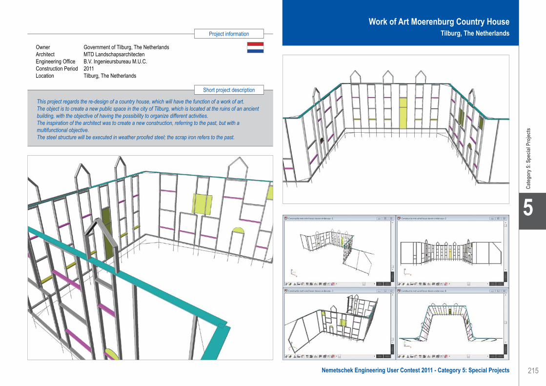
215
Project information
Short project description
Nemetschek Engineering User Contest 2011 - Category 5: Special Projects
Cate
gory
5: S
pecia
l Pro
jects
5
Owner Government of Tilburg, The NetherlandsArchitect MTD LandschapsarchitectenEngineering Office B.V. Ingenieursbureau M.U.C.Construction Period 2011Location Tilburg, The Netherlands
This project regards the re-design of a country house, which will have the function of a work of art.The object is to create a new public space in the city of Tilburg, which is located at the ruins of an ancient building, with the objective of having the possibility to organize different activities.The inspiration of the architect was to create a new construction, referring to the past, but with a multifunctional objective. The steel structure will be executed in weather proofed steel; the scrap iron refers to the past.
Work of Art Moerenburg Country HouseTilburg, The Netherlands
B.V. Ingenieursbureau M.U.C. . . . . . . . . . . . . . . . . . . . . . . . . . . . Work of Art Moerenburg Country House - Tilburg, The Netherlands

216
5
Cate
gory
5: S
pecia
l Pro
jects
Establis . . . . . . . . . . . . . . . . . . . . . . . . . . . . . . . . . . . . . . . . . . . . Roof Structure Housing Project ‘Gouden Boom’ - Bruges, Belgium
EstablisContact Bart MaertenAddress Beversesteenweg 612 8800 Roeselare, BelgiumPhone +32 51 43 12 00Email [email protected] www.establis.eu
Dakstructuur Woonproject ‘Gouden Boom’ - Brugge, België
InleidingHedendaagse architecturale vormgeving in een authentieke en historische stad als Brugge. Dat is ‘Gouden Boom’: thuiskomen in een omgeving waar het goed is om te wonen.
Een uniek woonproject met een ‘ingetogen’ architectuur. Met respect voor haar rijke verleden werd de voormalige brouwerij ‘De Gouden Boom’ getransformeerd tot een project van een absolute topklasse.
Via een hedendaagse architectuur werden appartementen, winkels en de museumbrasserie harmonieus verweven met de Brugse stadskern. Het beschermde Mouterijgebouw en de gerestaureerde woning met trapgevel werden stijlvol geïntegreerd.
‘Gouden Boom’ vertelt ons een boeiend verhaal van mensen die komen en gaan. Van wisselende activiteiten. Van ondernemingsgeest die hand in hand gaat met comfortabel wonen. Een verhaal van leven en beleven. Een intiem micro-sociaal wereldje in Brugge.
OntwerpOp de site van ‘Gouden Boom’ worden 5 individuele stadswoningen gecombineerd met appartementen en handelsruimtes. Tussen de verschillende gebouwen bevindt zich een zonovergoten binnenhof. Samen met de groendaken, daktuinen en dakterrassen vormt de binnenhof een prachtig groene intermezzo. Dankzij de ondergrondse parking worden alle gebouwen onderling met elkaar verbonden.
Op de illustraties is duidelijk te zien dat de dakvlakken over meerdere bouwlagen doorlopen. Dit resulteert in atypische vormen die de beleving van bewoners en bezoekers verhogen. In combinatie met de groendaken, daktuinen en dakterrassen leidt dit tot een uitermate complexe hoofdstructuur van het dak. Het dak wordt opgebouwd met stalen spanten en gordingen. De inplanting van de spanten dient rekening te houden met de locatie van de dakterrassen en de draagstructuur van de onderliggende verdiepingen. Het zal dus niet verbazen dat het ontwerp van de hoofdstructuur van het dak een complexe opdracht was. In de aanbestedingsfase van het project werd de structuur globaal gedimensioneerd met behulp
van 2D-modellen in Scia Engineer. Eén maal in uitvoering was het uiteraard vereist te staalstructuur te optimaliseren en de reacties van de dakstructuur op de onderliggende structuur exact te bepalen. Daarom werd er geopteerd om een volledig 3D-model te maken van de hoofdstructuur van het dak.
Scia SoftwareDe 3D-Autocad tekening van de architecten werd gebruikt als basis voor de opbouw van het rekenmodel. Met de diverse tekentools was het relatief eenvoudig om de dakstructuur in te geven in Scia Engineer. De belastingen werden op de structuur geplaatst met behulp van belastingspanelen, één van de nieuwste functionaliteiten van Scia Engineer. De belastingspanelen zorgen voor een correcte overdracht van de lasten naar de stalen hoofdstructuur en het is niet meer nodig om per dakligger de lasten eerst te gaan bepalen om die dan te kunnen ingeven in het rekenmodel.
Aangezien de dakspanten doorlopen over meerdere verdieping was het mogelijk om de horizontale trekkers ook te laten functioneren als opvangligger voor de verdiepingsvloeren. De horizontale windkrachten worden via de vloeren afgeleidt naar de trap- en liftkokers in de gebouwen. Dankzij het 3D-model en de optimalisatietools van de rekensoftware kon de hoeveelheid staal voor de dakstructuur gevoelig gereduceerd worden. Eens de dakstructuur was geoptimaliseerd konden de horizontale en verticale reacties van de dakstructuur op de onderbouw uit het model gehaald worden om deze dan te gebruiken voor de globale lastendaling.
In uitvoering zal het rekenmodel doorgegeven worden aan de staalconstructeur van het dak. Deze kan op zijn beurt de verbindingen in detail gaan ontwerpen op basis van de interne krachten die uit het model kunnen gehaald worden. Op deze wijze zal het 3D-rekenmodel optimaal benut worden wat resulteert in een verkorte studietijd voor de verschillende partijen.
Establis Group is een engineeringsbureau, gespecialiseerd in het creatief ontwerpen en berekenen van bouwkundige structuren, met een bewust gevoel voor realiteit. We houden ook van vlotte communicatie. Establis speelt vandaag de hoofdrol in een boeiend en groeiend succesverhaal.
Om de groei van Establis te bestendigen, was een nieuwe structuur nodig. Nu is Establis Group een feit.
Establis Group overkoepelt Establis Roeselare, Establis Antwerpen, Establis Leuven
(het vroegere IKDV) en Asysto. Hierdoor kunnen onze ingenieurs voortaan ook grotere nationale en internationale projecten aan.
Vandaag is Establis Group een stabiliteitsbureau met sterke fundamenten, klaar voor de toekomst.
Wij worden graag uw betrouwbare partner voor slimme en creatieve stabiliteitsoplossingen. Iedereen spreekt dezelfde taal als het over stabiliteit gaat. De taal van Establis.
Software: Scia Engineer

217
Project information
Short project description
Nemetschek Engineering User Contest 2011 - Category 5: Special Projects
Cate
gory
5: S
pecia
l Pro
jects
5
Roof Structure Housing Project ‘Gouden Boom’Bruges, Belgium
Establis . . . . . . . . . . . . . . . . . . . . . . . . . . . . . . . . . . . . . . . . . . . . Roof Structure Housing Project ‘Gouden Boom’ - Bruges, Belgium
Owner BPIArchitect 3architectenGeneral Contractor MBGEngineering Office EstablisConstruction Period From January 2010 to ...Location Bruges, Belgium
This project is about the roof structure of ‘Gouden Boom’. The ‘Gouden Boom’ is a unique housing project in the authentic and historical centre of Bruges. With respect for the past, the old brewery ‘De Gouden Boom’ was transformed to a top-class living project. Apartments, stores and city houses are combined in harmony with the city centre of Bruges. The project was developed by BPI, designed by 3architecten and calculated by Establis.

218
5
Cate
gory
5: S
pecia
l Pro
jects
Expo EngineeringContact Michael Lück, Andreas FritzAddress Suerkamp 14 59302 Oelde, GermanyPhone +49 2520-9129211Email [email protected]
Moving Arches - Muscat, Oman
‘Moving Arches’ at ‘The Royal Equestrian and Camel Festival 2011’
BackgroundEvery 5 years the Sultan of Oman organizes the Royal Equestrian and Camel Show. In this show 1.000 horses, 500 camels and about 1.500 musicians perform in a 2 hours show on January 1st. Via P.S.I. Performance Sales International GmbH, Paul Schockemöhle, Hank van Campen and Bert Okker have been involved in the organization of the show.
In a first concept drawing the designer team planned the 250 m wide stage assembly in the stadium with two movable, hovering arches flanking the central portal. The function of the arches is to narrow the visual field of the audience and focus the view on solo artists or smaller groups. The operating company PRG GmbH mandated Expo Engineering with the complete technical planning of the arch-structures and the drive mechanism of the arches.
The arches are equipped with show lighting, water fountains, pyrotechnics and decorations. The design of the arches had to be fragile and modern. The movement of the arches should work smooth and with a tangential speed of 50 m/min.
Starting the projectThe results of the feasibility study showed that there was no possibility for a hovering arch at one end. It was the demand of the client to use standard scaffolding for building the towers of the arches. The big overturning moment of the 40 m long arch was not to handle with scaffolding parts and led to a ground supported wheel solution. For this approach Expo Engineering made a first draft. The new static system allowed a 60 m long arch. Expo Engineering chose an attractive elliptical shape with a light framework solution. The cross section is tapered with a thin tip for the drive mechanics.
The calculation of the framework was done with Scia Engineer. It was essential to determine the steel profiles and the reactions to develop the drive mechanics and the bearings on top of the scaffold tower. Later, some flanges have been designed with Frilo.
Used modules in Scia Engineer:• The Import module was used to read a DXF directly
from the centre line of the 3D CAD.• Both ground supports (wheels of the drive
mechanics) have been set to “only compression” with a non-linear calculation.
• Wind loads have been generated directly by Scia Engineer Surface-Load-Generator.
• The steel profiles have been checked with the DIN 18800 module in Scia Engineer.
• The resonance frequency had to be checked, because the ground might be not even and bumpy. For this reason the Dynamic module was used.
Detailed DesignOn the top of the arch, the width was enhanced to 6 m to decrease the stress in the members caused by torsion as a reaction of wind and one lift-off support (wheel).
The whole steel structure was manufactured in Aurich, Germany and shipped to Muscat, Oman. This fact required a demountable construction with flanges in mainchords and braces for the transportation by truck. Also the rotating centre and the drive mechanism were designed demountable with bolted connections.
The bracing on top and bottom of the arch was carried out with half-round plate connections to realize a simple geometry of the tubes. The plates are notched and the tubes are placed in the slots to be connected with a fillet weld. So no different angles had to be cut.
For the calculation of shafts, gear boxes and shaft to collar connections programs for mechanical engineering have been used. Some parts have been calculated according to the Palmgren-Miner rules for fatigue analysis.
Founded in 1995, the engineering office Expo Engineering has emerged to an international specialist for engineering services in the event industry.
The core competences are:• Design and development• Construction• Static analysis
With at the time 9 engineers from the fields of mechanical engineering, structural engineering and event engineering, Expo Engineering is highly skilled in its genre.
This bundling of competences enables the realisation of complex requests with a new approach and an extended view for technical solutions.
The variety of services reaches from the static analysis of open-air-stages and grandstands up to complete development of fun rides.
Also temporary structures as tents or exhibition stands are subjects of Expo Engineering´s work.
Software: Scia Engineer
Expo Engineering . . . . . . . . . . . . . . . . . . . . . . . . . . . . . . . . . . . . Moving Arches - Muscat, Oman

219
Project information
Short project description
Nemetschek Engineering User Contest 2011 - Category 5: Special Projects
Cate
gory
5: S
pecia
l Pro
jects
5
Moving ArchesMuscat, Oman
Owner Sultan Quaboos Bin Said - Sultan of OmanArchitect Expo Engineering, Dipl.-Ing. Michael LückGeneral Contractor PRG GmbHEngineering Office Expo Engineering, Dipl.-Ing. Michael LückConstruction Start From March 2010 to December 2010Location Muscat, Oman
A spectacular event needs (e)motion. Every 5 years the Sultan of Oman organizes the Royal Equestrian and Camel Show. For the show 2011 two 60 m long elliptical shaped steel arches with an electric drive mechanism have been built. The arches, equipped with show lighting and pyrotechnics are movable to focus the audience´s view on solo artists in the centre of the stadium. The tapered cross section of the framework and the graceful design are impressive. The draft design, the implementation planning, the statics and the planning of the drive mechanism have been made by Expo Engineering.
Expo Engineering . . . . . . . . . . . . . . . . . . . . . . . . . . . . . . . . . . . . Moving Arches - Muscat, Oman

220
5
Cate
gory
5: S
pecia
l Pro
jects
grbv Ingenieure im Bauwesen GmbH & Co KGContact Björn HelfersAddress Expo Plaza 10 30539 Hannover, GermanyPhone +49 511984940Email [email protected] Website www.grbv.de
Yukon Bay im Zoo - Hannover, Deutschland
ProjektbeschreibungDer Erlebnis-Zoo der niedersächsischen Landeshauptstadt Hannover ist seit dem 22. Mai 2010 um eine Attraktion reicher. Nach 30 Monaten Bauzeit öffnete mit der Yukon Bay eine nach kanadischem Vorbild gestaltete neue Erlebniswelt ihre Pforten. Auf rund 22.000 m2 leben hier zukünftig über 100 Tiere in einer atemberaubenden Kulisse. Die Yukon Bay besitzt eine Hafenstadt mit Hafenbecken und dem gestrandetem Schiff „Yukon Queen“, 13.000 m² handmodellierte Bergflächen, einen Flusslauf sowie 18.000 Bäume und Sträucher. Zusätzlich wurden rund 200 Tonnen Natursteine verbaut.Generalplanung und Gesamtidee für die Themen- und Erlebniswelt Yukon Bay lagen in der Verantwortung von dan pearlman. Das Büro grbv Ingenieure im Bauwesen Gmbh & Co. KG erhielt den Auftrag für die Objekt- und Tragwerksplanung.
Von der Idee zur RealitätUm den ausgeklügelten Geometrien und Gelände-sprüngen der Yukon Bay gerecht zu werden, wurden diverse Spundwandbauwerke entwickelt. Da die Sohle der Baugrube bis zu 8 m unterhalb des Grundwasser-spiegels lag, musste die Baugrube trockengelegt werden. Damit kein Salzwasser aus den Becken in das Grundwasser gelangen kann, wurden besondere Anforderungen an das verwendete Spundwandsystem und die Bauausführung gestellt. Durch die Ingenieure von grbv wurden unter anderem die Ramm- und Verankerungspläne für das Projekt erstellt. Eine enorme Aufgabe, immerhin wurden für die Yukon Bay rund 730 Tonnen Spundwand verbaut. Damit die Geländeformationen wie geplant eingehalten werden konnten, war ein baubegleitendes Aufmaß nötig. Aus den Maßen wurden für fast jede der ca. 130 Ecken maßgenaue Passbohlen vor Ort gefertigt. Dazu waren etwa 3.000 m Trennschnitte und 5.000 m Schweißnähte erforderlich. Die Rückverankerung erfolgte mit Ischebeck-Titan-Mikroverpresspfählen und Kugelkopf-Anschlüssen.Da die Spundwandarbeiten den kritischen Pfad im Bauzeitenplan darstellten, wurden parametrisierte Typdetails für die Spundwände und Ankerpunkte entwickelt. So konnte wertvolle Zeit bei der Ausführung gespart werden.
Nach dem Voraushub erfolgte der Einbau von Gurtung und Verankerung. Nachfolgend wurde die Baugrube im Saugverfahren bis zur Unterkante der Unterwasser-betonsohlen ausgehoben. Der gesamte Erdaushub betrug ca. 11.500 m3.
Um später Zonen mit unterschiedlichen Wassertiefen zu erhalten, wurden die Sohlhöhen mit Trennwänden abgetreppt. Die stahlfaserbewehrten Sohlen selbst wurden im Kontraktorverfahren in verschiedenen Stärken hergestellt. In den verankerten Bereichen wurden 193 Bohrverpresspfähle mit Längen zwischen 15 und 18 m zur Auftriebssicherung eingesetzt. Die unverankerten Schwergewichtssohlen sind bis zu 1.90 m stark. Insgesamt wurden etwa 3.600 m3 UW-Beton eingebracht. Nach Herstellung der Auftriebspfähle wurde die Baugrube schließlich endgültig trockengelegt und die im Becken befindlichen Gebäude sowie die „Yukon Queen“ als Stahlbau in Schiffbauweise errichtet.
Weitere PlanungsinhalteNeben der Objekt- und Tragwerksplanung für die Ingenieurbauwerke wurde von grbv die Tragwerks-planung sämtlicher Hochbauten im Projekt Yukon Bay erbracht.
FazitNeben den allgemeinen Planungsanforderungen galt es insbesondere interdisziplinäre Faktoren wie z. B. Tiersicherheit, „Tieranprall“ oder Sprungweiten zu berücksichtigen und in die Planung zu integrieren.Somit wird klar, dass das Projekt Yukon Bay ein ganz besonderes Projekt darstellt. Es belegt, dass sich auch komplexe Aufgabenstellungen und Geometrien mit bewährten Bauverfahren und zur Verfügung stehenden ingenieurtechnischen Mittel kostensparend verwirklichen lassen.
Nicht zuletzt ist die Yukon Bay für den Erlebnis-Zoo Hannover ein überwältigender Erfolg, wodurch der Zoo die unangefochtene Tourismusdestination Nr. 1 der Region Hannover ist.Die Erstellung sämtlicher Zeichnungen für den Ingenieur- und Hochbau erfolgte mit dem Programm GLASER -isb cad-.
1926 gegründet, besteht grbv seit über 75 Jahren. Damit ist grbv eines der ältesten freischaffenden Ingenieurbüros Deutschlands und heute eine Büropartnerschaft von fünf beratenden Diplom-Ingenieuren.
Außerdem sind ca. 60 Mitarbeiter für Sie da: darunter 35 Ingenieure und 15 Konstrukteure. Erfahren, professionell und kompetent.
Eine solide Basis, Beständigkeit im Anspruch und Kontinuität in der Führung kennzeichnen grbv. Wir stellen hohe Anforderungen an uns und unsere Mitarbeiter, in deren Weiterbildung wir
kontinuierlich investieren. Die offene Einstellung zu unseren jungen Mitarbeitern bereichert uns im aktuellen und dynamischen Denken.
Das Verbinden von technischem Anspruch mit umweltfreundlichen Lösungen, das Entwickeln von außergewöhnlichen Ideen für unsere Auftraggeber, sind unsere Maßstäbe und der Anspruch, den wir an uns stellen. Der Auftraggeber steht im Mittelpunkt unserer Arbeit.
Neben unserem Hauptsitz in Hannover unter-halten wir Standorte in Berlin und Oschersleben.
Software: GLASER -isb cad-
grbv Ingenieure im Bauwesen GmbH & Co KG . . . . . . . . . . . . . Yukon Bay - Zoo - Hannover, Germany

221
Project information
Short project description
Nemetschek Engineering User Contest 2011 - Category 5: Special Projects
Cate
gory
5: S
pecia
l Pro
jects
5
Owner Zoo Hannover GmbHArchitect Dan Pearlman Erlebnisarchitektur GmbHGeneral Contractor Dan Pearlman Erlebnisarchitektur GmbHEngineering Office grbv Ingenieure im Bauwesen GmbH & Co KGConstruction Period From January 2008 to May 2010Location Hannover, Germany
In May 2010 the Hannover Zoo in Germany opened its theme world ‘Yukon Bay’, a replica of the Canadian adventure landscape. The 22.000 m² theme world, one of Europe’s largest construction projects, provides a new home for over 100 animals of 15 species. This scenery includes two big basins filled with saltwater for polar bears and sea bears. Also a stranded vessel was designed by the engineers of grbv, responsible for the structural planning. For the basins with the buildings and vessel inside, a waterproof sheet pile wall including an underwater concrete sealing blanket with grouted anchors was constructed.
Yukon Bay in ZooHannover, Germany
grbv Ingenieure im Bauwesen GmbH & Co KG . . . . . . . . . . . . . Yukon Bay - Zoo - Hannover, Germany

222
5
Cate
gory
5: S
pecia
l Pro
jects
IGUBA, s.r.o. . . . . . . . . . . . . . . . . . . . . . . . . . . . . . . . . . . . . . . . . Hockey Hall - Senec, Slovak Republic
Hockey Hall - Senec, Slovak Republic
Description of the steel structureThe steel structure of the hall has 8 modules A-H of transversally stiffened frames made of rolled profiles with an axial distance of 6.50 m. An extra 19.95 m module is inserted between the first and last module, which means that the overall length of the hall is 7 x 6.50 + 2 x 19.95 = 85.40 m. The overall width of the hall is 2 x (7.70 + 19.95) = 55.30 m. The axial distance of the transversal joints is 33.80 m. The main columns support stiffened beams with their lower edges at the height of 12.50 m.
The supporting structure of the hall is made of steel and consists of vertical rolled columns HEA 600, stiffened cross beams and longitudinal rolled beams HEA 200 and HEA 300 with transversal as well as longitudinal stiffening in horizontal and vertical planes. On the supporting steel elements there are externally affixed sandwich panels (30 kg/m²) protecting the hall against wind and rain. Illuminators of a maximum weight of 5 kg/m² will be hung on the lower flange of the stiffened beam.
Description of the steel structure partsThe primary supporting system of the building was considered in the static calculation as one special unit. The steel columns consisting of profiles HEA 600 have a height of 12.500 mm in the highest point of the countertype roof. On the columns there are inserted beams - lattice girders, verticals and diagonals which have been designed using double angle profiles of various dimensions. Longitudinal beams made of profiles HEA 200 and HEA 300 are welded to the upper chord. Statically they are considered as simple beams, on which sandwich panels of the roof are inserted.
The connection to columns and beams is made through steel sheet flanges and bolts. Floor beams are made of open-section rolled steel beams. The parts are connected with bolts during the erection phase.
FoundationsThe steel columns are supported by reinforced concrete foundation pads made of concrete of class C16/20. The dimensions of the reinforced concrete foundation pads in the ground plan are 2.200 x 2.200 mm and they reach to the depth of 2.000 mm. The foundation pads
are located on concrete piles (each one with a bearing capacity of 500 kN). The foundation of the building was quite a challenge. The seismicity is of 7o MSK-64, category “A”.
Material and loading dataThe foundation and load-bearing elements were designed according to ENV 1993-1-1:1992 Eurocode 3. The design of the building consists of the calculation and evaluation of a number of load cases and their complex combination effects: in addition to the dead load (self weight) also the live load was considered - in this case only the illuminators. No service platforms, which would increase the load of the supporting steel structure, were designed.
The snow loading (area II.) was equal to 0.70 kN/m2 and the wind loading was wo = 0.55 kN/m2 (during the erection phase and on the final building). Moreover, seismicity 7o MSK-64, category “A” was considered as well as temperature loading (during the operation the shell structure has a higher temperature than the column support).
Description of the static calculation methodThe static calculation was prepared with the software NEXIS (ESA Prima Win) rel. 3.100. 24. The most critical combinations were calculated according to ENV 1993-1-1:1992 Eurocode 3 with the coefficient set to 1.35 in two basic combinations (load-bearing capacity and deformations).
The model contains 291 nodes, 514 bars and 100 1D macros. The model has 5 different profile sections made of both basic materials, i.e. steel and concrete. The basic linear calculation module (3D frame) has solved over 10.000 equations.
Software: Nexis
The company IGUBA was established in 1997. The owner, Ivan Guba, is a static engineer who works on his own. The annual turnover amounts from 60.000 to 75.000 Euros.
Structural engineering• Civil engineering: all about static and
construction• Design of the static of residences and
commercial buildings.• Diagnostics of bearing constructions.• Technical consulting.
Some projects since 1990:• Secondary Combustion Chamber & Steam
Boiler and Flue Gas Cleaning (DK)• Object of Furniture ATRIUM Bratislava (SK)• Steel Structures of many Tank- and Oil-
Stations „AVANTI“ (now SHELL) (SK, CZ, HU, AU, RO, etc.)
• Commercial building „Swietelsky“ (SK)• Technological Center E.O.S. Žilina (SK)• Hockeyball Hall Macharova Bratislava (SK)• Shopping-storing project Vajnorska (SK)• Emporia Towers Buildings in Bratislava (SK)
IGUBA, s.r.o.Contact Ivan GubaAddress Miletičova 70 82109 Bratislava, Slovak RepublicPhone +421 253416692Email [email protected]

223
Project information
Short project description
Nemetschek Engineering User Contest 2011 - Category 5: Special Projects
Cate
gory
5: S
pecia
l Pro
jects
5
Owner City SenecArchitect Pavel KosnáčGeneral Contractor City SenecEngineering Office IGUBA, s.r.o.Construction Period From January 2011 to October 2011Location Senec, Slovak Republic
Hockey HallSenec, Slovak Republic
IGUBA, s.r.o. . . . . . . . . . . . . . . . . . . . . . . . . . . . . . . . . . . . . . . . . Hockey Hall - Senec, Slovak Republic
This project presents the static calculation of a 283 ton heavy steel structure (S235) for the hockey hall in the town of Senec - Slovak Republic. The steel structure was mounted from January to September 2010. The total length of this construction is 85.6 m; it has a width of 55.3 m, a total area of 4.600 m² and a volume of more than 40.000 m³. The building costs are 5.000.000 Euro. The hall can be used by approximately 2.500 visitors. Hockey halls are rather rarely realized in the Slovak Republic which makes the realization of this type of building all the more interesting.

224
5
Cate
gory
5: S
pecia
l Pro
jects
Ingenieurbüro für Bauwesen Dipl.-Ing. (TU) Johann SchlattnerContact Cornelius Schlattner, Adrian VolmerAddress Weißenburger Str. 9 49076 Osnabrück, GermanyPhone +49 541 46007Email [email protected] www.schlattner.de
Renovierung Millerntor Stadion - Hamburg, Deutschland
Um das Stadion am Millerntor den heutigen Anforderungen von Zuschauern und Veranstaltern anzupassen, entschied sich die Vereinsführung des FC St. Pauli im Jahr 2006 zum schrittweisen Umbau seiner Heimspielstätte. Zunächst wurde die Südkurve seit Dezember 2006 neu gebaut, in der neben den gewünschten Logen nun auch Umkleidekabinen und Geschäftsstelle untergebracht sind. Die konkreten Planungen des 2. Bauabschnittes des neuen Stadionteilstücks der Westtribüne begannen bereits 2009, die ersten Bagger zum Umbau der neuen Haupttribüne rollten im Januar 2010.
Die Tragwerksplanung und Planung des vorbeugenden Brandschutzes des 17 Mio. Euro Projekts unterliegt der ARGE Ingenieurbüro Adrian Volmer & Ingenieurbüro Johann Schlattner. Beide Büros setzen seit vielen Jahren auf die CAD-Lösungen von GLASER -isb cad-.
Die neue Westtribüne des Stadions umfasst 4.800 Sitzplätze, davon 1.800 Business-Seats sowie 28 Separees. 8.000 m2 Nutzfläche auf drei Ebenen bieten Platz für Verkaufsstände, Eventräumlichkeiten und Stadiontechnik. Die Konstruktion besteht aus Stahlbetondecken mit Halbfertigteilunterzügen und Stahlbeton-Fertigteilstützen. Zwischen Haupt- und Südtribüne entsteht zudem eine neue Eckbebauung. Zwei Ebenen des Gebäudes beherbergen ab Herbst 2010 die weltweit erste Kindertagesstätte in einem Fußballstadion. Ca. 100 Kinder bis zum Alter von
6 Jahren können in der 1385 Quadratmeter großen Einrichtung betreut werden. Die beiden Dachspielplätze des „Piraten-Nests“ laden auf 350 m2 zum Spielen ein. Bei der Konstruktion der Eckbebauung kommen Flachdecken mit Stahlbetonstützen und Stahlbetonwandscheiben zum Einsatz. Die filigrane Dachkonstruktion besteht aus Stahl-Fachwerkbindern, die als Kragarme die Tribünen überspannen. Im Endausbau verfügt das Stadion, dessen Umbau mit geschätzten Kosten von 32 Millionen Euro veranschlagt wurde über 27.500 Zuschauerplätze, darunter 15.000 Stehplätze. Damit würde das Stadion am Millerntor den Anforderungen des DFB und der DFL hinsichtlich Stadionkomfort, -größe und -sicherheit sowie hinsichtlich technischer und infrastruktureller Ausstattung genügen. Die Fertigstellung ist für 2014 geplant.
Ingenieurbüro SchlattnerDas Ingenieurbüro Schlattner, 1986 vom Inhaber Dipl.-Ing. (TU) Johann Schlattner in Osnabrück gegründet, erarbeitet in enger Zusammenarbeit mit Bauherren, Architekten und ausführenden Unternehmen eine optimale Gesamtkonzeption für Projekte aus allen Bereichen des Hoch- und Ingenieurbaus. Es folgt dabei stets der Philosophie die Wünsche des Bauherrn, die architektonischen Vorgaben sowie die konstruktiven Erfordernisse und Notwendigkeiten aus der Gebäude-technik in einer wirtschaftlichen und funktionalen Bauweise zu vereinen. Der Tätigkeitsbereich des Ingenieurbüro Schlattner erstreckt sich dabei auf alle Ingenieurleistungen im Bauwesen, wobei das Hauptaufgabengebiet in der Erstellung von statischen Berechnungen einschließlich der dazugehörigen Ausführungsplanung im Bereich Stahl-, Stahlbeton, Massiv- und Holzbau, der Sachverständigentätigkeit in den Bereichen des vorbeugenden Brandschutzes und der Bauphysik für Projekte im europäischen Umland liegt.
Ingenieurbüro VolmerAls Fachplaner für Tragwerksplanung versteht sich das Ingenieurbüro Volmer als unabhängiger Treuhänder des Auftraggebers und wichtiger Partner eines Bauteams. Der Inhaber des Ingenieurbüros, Dipl.-Ing. Adrian Volmer, Jahrgang 1967, ist Beratender Ingenieur und staatlich anerkannter Sachverständiger für Schall- und Wärmeschutz. Das Leistungsspektrum des Ingenieu-rbüro Volmers erstreckt sich von der Tragwerksplanung, der Bauphysik, Abwicklung und Ausschreibung von Projekten, bis hin zur Baukostenoptimierung und Bausstoffberatung. Es verfolgt dabei stets das Ziel Bau-konstruktionen so zu optimieren, dass wirtschaftliche und praktikable Lösungen entstehen und eine termin-gerechte Fertigstellung aller Aufträge zu gewährleisten.
Daten und Fakten zum Stadion am MillerntorFC St. Pauli von 1910 e.V.Stadionbau: • Beginn der Bauarbeiten für das Stadion, 1961 • Ausbau Südtribüne, 2007 • Ausbau Haupttribüne, 2010
Zuschauerkapazität: 24.850; 11.792 Sitzplätze (überdacht),12.695 Stehplätze (unüberdacht).
Die ARGE Ingenieurbüro Volmer und Ingenieurbüro Schlattner realisieren seit einigen Jahren gemeinsam Projekte im Bereich des Hoch- und Ingenieurbaus. Durch die Zusammenarbeit konnten bereits mehrere Projekte wie die hier vorgestellte Rekonstruktion des Stadions am Millerntor erfolgreich umgesetzt werden. In ihrer Arbeitsgemeinschaft verfolgen die beiden Büroinhaber Dipl.-Ing. Adrian Volmer und Dipl.-Ing. (TU) Johann Schlattner stets das Ziel durch Kompetenz, Kreativität und Termintreue, unterstützt durch engagierte Mitarbeiter, eine hohe Qualität in
ihren Leistungen zu erreichen. Nur so ist nach ihrer Auffassung die optimale Gesamtkonzeption eines Projekts zu finden und lassen sich die Wünsche des Bauherrn, die architektonischen Vorgaben und konstruktiven Erfordernisse in einer wirtschaftlichen und funktionalen Bauweise vereinen.
Software: GLASER -isb cad-
Ingenieurbüro für Bauwesen Dipl.-Ing. (TU) Johann Schlattner . . . . . . . . . . . . . . . . . . . . . . . . . . . . . . . . . Millerntor Stadium Renovation - Hamburg, Germany
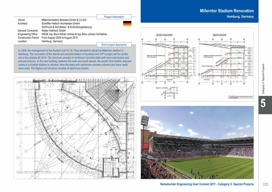
225
Project information
Short project description
Nemetschek Engineering User Contest 2011 - Category 5: Special Projects
Cate
gory
5: S
pecia
l Pro
jects
5
Owner Millerntorstadion Betriebs-GmbH & Co.KGArchitect Scheffler Helbich Architekten GmbH Dortmund & Architektur- & Einrichtungsplanung General Contractor Walter Hellmich GmbHEngineering Office ARGE Ing.-Büro Adrian Volmer & Ing.-Büro Johann SchlattnerConstruction Period From August 2009 to August 2010Location Hamburg, Germany
In 2006, the management of the football club FC St. Pauli decided to rebuild its Millerntor stadium in Hamburg. The renovation of the stands and accommodation of business and VIP lounges will be carried out in four phases till 2014. The structure consists of reinforced concrete slabs with semi-cast beams and precast columns. In the new building, between the main and south stands, the world’s first children daycare centre in a football stadium is situated. Here flat slabs with reinforced concrete columns and shear walls were used. The filigree roof structure consists of steel truss beams.
Millerntor Stadium RenovationHamburg, Germany
Ingenieurbüro für Bauwesen Dipl.-Ing. (TU) Johann Schlattner . . . . . . . . . . . . . . . . . . . . . . . . . . . . . . . . . Millerntor Stadium Renovation - Hamburg, Germany

226
5
Cate
gory
5: S
pecia
l Pro
jects
Oostdijckbank Radar Post Helicopter Platform - Nieuwpoort, Belgium
IntroductionThe SRK (Scheldt Radar Chain) manager plans to discontinue the use of the helicopter type currently used to transport maintenance staff to and from the Oostdijckbank Radar Post. It would like to make the radar post accessible for Belgian naval helicopters. The new helicopter type (NH-90) is considerably heavier, which results in significantly higher static and dynamic loads on the steel platform structure of the helicopter tower. On behalf of SRK, Soresma NV asked Oranjewoud to perform a structural analysis of the existing helicopter tower and to draw up specifications for the necessary structural alterations.
Description of the radar postThe Oostdijckbank Radar Post consists of a radar tower and a helicopter tower connected by a footbridge. The radar tower houses technical systems while the helicopter tower is made up of a helicopter platform with a workshop underneath. Fuel and water tanks are accommodated within the actual tower.
The main structure/foundation of the helicopter tower consists of a single tubular pile with a diameter of 3.0 m. The foundation depth of the tubular pile is -25.000 m MLLWS. The top of the tubular pile is at +17.500 m MLLWS. The elevation of the helicopter platform itself is + 21.000 m MLLWS. There are two more platforms at + 17.500 m MLLWS and + 15.000 MLLWS, respectively. The helicopter platform and the lower platforms are made up of a girder structure, topped with steel plate in case of the helicopter platform and workshop, and with a steel grating in case of the lower platform. The girder structure of the helicopter platform and the middle platform are supported by columns on the bottom platform, which in turn is supported by shoring on the tubular pile.
Main characteristics:• Monopile dimensions: Ø 3.000 x 30 mm, L = 42.5 m,
S355J2G3 grade steel• Helicopter platform deck: sheet steel thickness 20 mm,
orthogonal grid of HEA280 on HEA500 beams• S235JO grade steel• Platforms at + 17.500 m and + 15.000 m MLLWS in
a design with tangentially positioned IPE200 beams
between 8 radially positioned IPE360 beams of S235JO grade steel
• Total weight of helicopter tower (steel): 212 metric tons.
Use of Scia EngineerAccording to the existing calculations the capacity reserve of the helicopter platform is limited. For this reason, it was decided to model the entire steel structure in Scia Engineer, 3D FEM software. The monopile and the beams were modeled with beam elements and the cover plates of the platforms at + 21.000 m and + 17.500 m were modeled with plate elements. The staircases connecting the three platforms and the hoisting beam for the rescue boat are also included in the model. The connecting bridge between the radar tower and the helicopter tower, the grating elements and the wall elements were not modeled in Scia Engineer. The effects of the distribution of horizontal load of the wall elements are handled by adding shoring between the columns.
A total of four computational models were created.These computational models all have the same structure, with the exception of the horizontal spring constants that support the monopile and the load combinations that were calculated.
The following computational models were created:1. Extreme situation according to BS6349 2. Normal-1 situation according to BS63493. Normal-2 situation according to BS63494. Combinations according to EN-1990
Models 1 to 3 are used to check the strength and stability of the monopile according to BS6349. For these models, the wave and current loads (according to the Shore Protection Manual) and the wind loads (according to EN-1990) were applied. Model 4 is used to calculate and check the steel structure of the platforms according to NEN6770 and NEN6771. With model 4 the normative helicopter landing conditions according to the Heliport Manual (ICAO) are calculated.The 3D-FEM modeling, in Scia Engineer, of the helicopter tower ensured that the load distribution was optimized, while the necessary structural alterations were kept to a minimum.
Software: Scia Engineer
Oranjewoud: A world of opportunity!Comfortable living, work, travel and recreation are only possible with a proper understanding of space. Oranjewoud’s fields of activity consequently range from urban development, mobility, construction and property to rural development, water, the environment, safety, sport and recreation. We operate in the Netherlands and on an international scale too. Oranjewoud was a major force in land management under Frisian management some 60 years ago. Our organisation has developed into an all-
round partner and is much more than just an engineering consultancy.
MissionOranjewoud aims to be a leading partner in the development and application of sustainable and integral solutions relating to all aspects of our living environment, such as home, work, recreation, mobility and the environment.
Core valuesEnterprising, People-oriented, Development, and Character.
Ingenieursbureau Oranjewoud B.V.Contact Vincent DolsAddress Postbus 40 4900 AA Oosterhout, The NetherlandsPhone +31 162 487114Email [email protected] www.oranjewoud.nl
Ingenieursbureau Oranjewoud B.V.. . . . . . . . . . . . . . . . . . . . . . . Oostdijckbank Radar Post Helicopter Platform - Nieuwpoort, Belgium

227
Project information
Short project description
Nemetschek Engineering User Contest 2011 - Category 5: Special Projects
Cate
gory
5: S
pecia
l Pro
jects
5
Owner Schelde Radar KetenGeneral Contractor Iemants NVEngineering Office Ingenieursbureau Oranjewoud BV (original design Haecon & Iemants)Construction Period From 2000 to 2002Location Nieuwpoort, Belgium
The project is about alterations to the helicopter platform of the Oostdijckbank Radar Post in the Western Scheldt estuary. The radar post consists of a radar tower plus a helicopter tower. As in the future considerably heavier helicopters will be used, Oranjewoud was asked to perform a recalculation of the existing helicopter tower construction to determine if it would be possible to use the NH90 helicopter without extensive alterations to the tower. The results of the recalculation indicated that only a few components would be inadequate and Oranjewoud was asked to work out and draw up the specifications for the required alterations.
Oostdijckbank Radar Post Helicopter PlatformNieuwpoort, Belgium
Ingenieursbureau Oranjewoud B.V.. . . . . . . . . . . . . . . . . . . . . . . Oostdijckbank Radar Post Helicopter Platform - Nieuwpoort, Belgium

228
5
Cate
gory
5: S
pecia
l Pro
jects
Iv-ConsultContact Haowen ShiAddress Postbus 1155 3350CD Papendrecht, The NetherlandsPhone +31 786448555Email [email protected] www.iv-consult.nl
Park your Bike in an Apple - Alphen aan den Rijn, The Netherlands
As the bicycle is a popular means of transport in the Netherlands, it is not uncommon to encounter literally hundreds of bikes at or near major train stations. A unique bicycle parking facility in the shape of an apple, large enough for 1.000 bicycles, aptly named the ‘FietsAppel’ now takes centre stage at the new station boulevard.
Description of the structureTwo parallel upward spiralling curves constitute the basic geometry of the structure. The spirals ascend from the ground to a height of 16 m, moving gradually outwards. The two spiral beams, which are approximately 6 m apart, support a lightweight steel floor which has sufficient space to accommodate two rows of bicycle racks and a walkway in between. The outer spiral beam is supported by the ‘apple peel’, a triangulated space frame shell constructed of CHS struts and ties, while the inner spiral beam is carried by 9 CHS columns, inclined outwards at 15 degrees. At the tops of the columns there is a horizontal ring which ties the column tops together visually. This is the ‘core’. Near the top, the outer spiral beam moves back towards the inside, until the spiral blends into the top ring. In this way, a complete structural load bearing system is formed. Just above the centre of the top ring, a leaf shaped wind vane is positioned which has both a functional and aesthetic purpose. It consists of an aluminium leaf, a bearing mounted stalk and a cable staying suspension system. The cables are pre-stressed and are connected to the stalk housing in staggered fashion similar to the spokes in a bicycle wheel. This provides both translational and rotational stiffness.
Analysis approachApart from the complicated spatial geometry, figuring out how this unique structure behaves under the various loading conditions was also a challenge for the structural engineer. Horizontal stability under wind loading is not provided by the central core as would be the case in other conventional structural arrangements. This is due mainly to the architectural requirement that no bracing should be added to achieve stability. The stability is inherent in the framework thereby achieving the desired ‘transparent’ look. The central core which is
formed by the columns and top ring does not contribute at all to the structural stability. The structure receives its stability entirely from the triangulated outer peel which functions as a dome and can resist wind loads from any direction. Another interesting phenomenon is the effects of temperature change. Due to variations in the temperature of the steel members in direct sunlight and those in shaded areas, expansion and contraction of particular elements are not synchronized which results in the creation of additional internal member forces.
Use of Scia EngineerModelling a geometrically complex structure like the FietsAppel would be a challenge for any structural analysis program available today. The XML coding component of Scia Engineer makes this process not only possible but also surprisingly simple. The entire geometry of the apple was based on the two spiral curves, which were described mathematically and controlled by variables. MS Excel was used to calculate the spatial coordinates of the key nodes on the spiral beams and to generate the corresponding XML scripts for Scia Engineer. Thereafter a very simple parabolic arc beam was created in Scia and copied repeatedly until all of the previously defined key nodes were duplicated. In the tools category of Scia Engineer, an XML file consisting of the nodal data was generated. Then by simply updating the scripts in the XML file with those in the spreadsheet, the complete inner and outer spiral beams were generated automatically and precisely. In this way it was relatively easy to connect all the key nodes diagonally with the tubular members completing the model in a very short time. As with all projects of this nature, the geometry often requires some adjustment after the initial generation. Being able to modify the parameters in the mathematical formula and repeating the above process instead of redoing the entire model saved valuable time. A robust design has been achieved by eliminating certain members and analyzing the structural integrity for the remaining parts, for instance there is a possibility that a vehicle could collide into the structure and cause local failure or total collapse. In addition, a separate model for the ‘wind vaan’ was made in Scia Engineer to verify the correct behaviour of the pre-stressed cable-staying top structure.
Iv-Consult is a division of Iv-Groep, a group of professional engineering companies with approximately 800 employees. Iv-Groep was founded in 1949 as a design and drawing office for steel structures. Through the years the company has developed itself into a sparring partner for clients who need independent advice or a constructive solution.
Services are provided from preliminary design up to detail design. Iv-Consult is a market leader especially in detail design of steel structures. Besides the main office in Papendrecht, the
Netherlands, Iv-Consult also has offices in Almere, the Netherlands and Kuala Lumpur, Malaysia.
As an engineering company Iv-Consult focuses on the challenging design and engineering of complex structural and mechanical projects. The company has the know-how and experience to also realise larger scale projects like power plants and harbours. For clients varying from end-users to developers, architects to contractors, we provide engineering services with a creative mind setting and a high focus on cost effective design. Quality is our selling point.
Software: Scia Engineer
Iv-Consult . . . . . . . . . . . . . . . . . . . . . . . . . . . . . . . . . . . . . . . . . . Park your Bike in an Apple - Alphen aan den Rijn, The Netherlands

229
Project information
Short project description
Nemetschek Engineering User Contest 2011 - Category 5: Special Projects
Cate
gory
5: S
pecia
l Pro
jects
5
Owner Municipality of Alphen aan den RijnArchitect KuipersCompagnonsGeneral Contractor Jos van den Bersselaar ConstructieEngineering Office Iv-ConsultConstruction Period From April 2010 to October 2010Location Alphen aan den Rijn, The Netherlands
A unique bicycle parking facility in the shape of an apple, large enough for 1.000 bicycles, aptly named the ‘FietsAppel’ now takes centre stage at the new station boulevard in Alphen aan den Rijn, the Netherlands. Two parallel upward spiralling curves constitute the basic geometry of the structure. The structure consists of a triangulated space frame shell (‘apple peel’), 9 CHS columns with spiral beams (‘apple core’) and bearing mounted stalk with a cable staying suspension system (‘apple stalk’ and ‘apple leaf’). By implementing XML scripts coding in Scia Engineer, a parametric model is achieved which saves lots of modelling time.
Park your Bike in an AppleAlphen aan den Rijn, The Netherlands
Iv-Consult . . . . . . . . . . . . . . . . . . . . . . . . . . . . . . . . . . . . . . . . . . Park your Bike in an Apple - Alphen aan den Rijn, The Netherlands

230
5
Cate
gory
5: S
pecia
l Pro
jects
Stellingbouw in Atrium van Shopping Centrum - Kortrijk, België
Eind 2008 kreeg KAEFER België van hun opdrachtgever THV Wijngaard (Tijdelijke Handelsvereniging Van Roey NV en Van Laere NV) de complexe opdracht om stellingen te bouwen in het atrium van het winkelcentrum Sint-Janspoort te Kortrijk (K in Kortrijk).
De opdracht bestond, naast het monteren, verhuren en demonteren van de stellingen, in eerste instantie uit het ontwerpen van:• Enerzijds een gigantische ruimtestelling met één
werkvloer bovenaan t.b.v. de bereikbaarheid van de glazen koepel in combinatie met werkvloeren om de 2 m aan de wanden t.b.v. metselwerken.
• Anderzijds de ondersteuningsconstructies voor de te monteren delen van de zware stalen spanten van de glazen koepel.
Bij het ontwerp van de ruimtestelling werd gebruik gemaakt van de software Scia Engineer o.m. ter bepaling van de optredende reactiekrachten onderaan in de spindels. De ondergrond (betonnen plaat niveau +1) die als aanvangsniveau voor de stelling fungeerde, kon slechts een beperkte belasting dragen (maximale
puntlasten van 4 ton). Bijkomende vereiste van de opdrachtgever: zo weinig mogelijk steunpunten.Na een eerste onderzoek bleek dat de combinatie van beide beperkingen niet zomaar haalbaar was.Pas na een intensieve periode van ‘trial and error’ heeft KAEFER een voor de opdrachtgever ideale constructie ontworpen. Om de belasting van de zwaarst belaste steunpunten op de betonplaat maximaal te spreiden, werd gekozen voor een speciale stellingbouwtechniek om de krachten naar de onderliggende betonplaten af te leiden.
De ondersteuningstorens voor de enorme stalen spanten werden in combinatie met de ruimtestelling opgebouwd, doch onafhankelijk belast. De op te nemen verticale kracht per ondersteuningspunt van deze stalen spanten bedroeg 19 ton. Gezien de beperkte afmetingen van de ondersteuningstorens (1.57 m x 1.57 m) werden speciale stellingconstructies ontwikkeld om dit te verwezenlijken. In totaal werden 27 torens opgebouwd met een hoogte van 23 m.
Afmetingen ruimtestelling:• Lengte: 112 m• Breedte: 27.50 m• Hoogte: 17.00 m• Totale stellingvloeroppervlakte:
5.000 m² (= 1 voetbalveld)• Standtijd stellingen: april 2009 tot eind 2009
Het project in cijfers:• Aantal m³ stelling: 54.000 m³• Aantal kg materiaal: 450.000 kg = 450 ton
(= 200 zeecontainers 20 ft)• Aantal lopende meter buis/vlonder = 88.000 m
= 88 km
KAEFER Benelux is gespecialiseerd in het ontwerpen, monteren en demonteren van specifieke ‘op maat’ gemaakte stellingconstructies (zware ondersteuningsconstructies, grote volumestellingen, hangstellingen, laadplatformen, etc.) en beschikt dan ook over een eigen Studiedienst Stellingbouw, die o.a. gebruik maakt van Scia Engineer voor het berekenen en dimensioneren van stellingconstructies.
KAEFER België NVContact Veerle SchelfhoutAddress Europark Noord 20B 9100 Sint-Niklaas, BelgiumPhone +32 3 7891588Email [email protected] www.kaefer.be
KAEFER is actief in: warmte- en koude-isolatie, stellingbouw, geluidswering en brandbeveiliging, in de industrie, offshore, scheepsbouw, constructie en ruimtevaart.Wereldwijd heeft KAEFER vestigingen in meer dan 40 landen, met een personeelsbestand van meer dan 15.000 werknemers.KAEFER België N.V. en KAEFER Nederland B.V. zijn vooral actief op het gebied van stellingbouw, isolatie, leidingverwarming en asbestverwijdering, voornamelijk in de industrie. Beide ondernemingen voeren regelmatig grote projecten en shutdowns uit op nucleaire,
chemische en petrochemische bedrijven.Daarnaast zijn zij ook actief in de bouwsector op het gebied van renovatie en utiliteitsbouw.KAEFER Benelux beschikt in volledige eigendom over een zeer grote hoeveelheid originele Layher materialen (Allround en Blitz) en beschikt over voldoende resources om grote projecten te kunnen realiseren. De laatste jaren specialiseert de afdeling stellingbouw zich in het ontwerpen, monteren en demonteren van specifieke ‘op maat’ gemaakte stellingconstructies.
Software: Scia Engineer
KAEFER België NV . . . . . . . . . . . . . . . . . . . . . . . . . . . . . . . . . . . Scaffolding in Shopping Centre Atrium - Kortrijk, Belgium

231
Project information
Short project description
Nemetschek Engineering User Contest 2011 - Category 5: Special Projects
Cate
gory
5: S
pecia
l Pro
jects
5
Owner Foruminvest Group / Union Investment Real EstateArchitect Robbrecht en Daem architecten General Contractor THV Wijngaard (Tijdelijke Handelsvereniging Van Roey NV - Van Laere NV)Engineering Office TechnumConstruction Period From 2005 to 2009Location Kortrijk, Belgium
KAEFER Belgium built a complex assembly of scaffolds in the atrium of the mall ‘Sint-Janspoort’ in Kortrijk. Besides the hiring out, the assembly and disassembly of the scaffolds, the assignment consisted in the design of a gigantic floored scaffold for works on the enormous glass dome, this combined with lateral scaffolds, each of 2 m of height, for the masonry work at the sidewalls as well as in delivering the support structures for the heavy steel frames of the glass dome. To shorten the execution time was chosen to use the stross’ method, which is building in two directions at the same time, both upwards and downwards.
Scaffolding in Shopping Centre AtriumKortrijk, Belgium
KAEFER België NV . . . . . . . . . . . . . . . . . . . . . . . . . . . . . . . . . . . Scaffolding in Shopping Centre Atrium - Kortrijk, Belgium

232
5
Cate
gory
5: S
pecia
l Pro
jects
Software: Scia Engineer
Kiosk ‘de Plaatse’ - Veldhoven, Nederland
InleidingDorpsplein ‘De Plaatse’, het hart van Veldhoven-Dorp, heeft een ware metamorfose ondergaan.
En dat was ook hard nodig, want jarenlang lag het plein en de oude kiosk er slecht bij, met vandalisme en drugsgebruik als ongewenste bijverschijnselen.
Aanvankelijk kreeg architect ir. Frank Beek de opdracht van de gemeente Veldhoven om de renovatiemogelijkheden van de bestaande kiosk te onderzoeken.
Behalve het feit dat de bestaande kiosk bijna geheel opnieuw gebouwd diende te worden, waren er voor de architect een aantal belangrijke situatieve argumenten om een alternatief ontwerp te maken voor een nieuwe kiosk.
Uitgangspunten1. De kiosk zou zich moeten oriënteren op het, nieuw in
te richten plein, en dienen als podium voor het plein.2. De kiosk zou integraal ontworpen moeten worden
met het plan om het sterk vervuilde beekje ‘de Gender’, dat aan de rand van het plein stroomt, in een ecologische zone te veranderen.
3. Door de kiosk ook tevens te oriënteren op die nieuwe natuur krijgt hij, naast zijn podiumfunctie, ook de kwaliteit van verblijfs- en ontmoetingsgebied.
Daarnaast zou de nieuwe kiosk geen gesloten achterwanden moeten krijgen, zoals dat bij de oude kiosk het geval was. Door deze transparantie kunnen, voor de omgeving onzichtbare activiteiten, zoveel mogelijk worden voorkomen.
De natuur van de nieuwe Gender en de cultuur van de nieuwe kiosk ontmoeten elkaar op een kruispunt van wandelroutes langs de Gender en de route naar de Kromstraat voor het winkelend publiek.
De kiosk staat met de achterzijde in het water van de Gender en kraagt vanuit het podium uit over het water, het laatste deel met open vloerroosters.
De architectuur van de kiosk is mede bepaald door de ambitie een eigentijds en herkenbaar object te ontwerpen.
In nauw overleg met constructie adviesbureau Krekon BV is het ontwerp van maquette naar 3D-model doorontwikkeld.
Hierbij is beton als materiaal gekozen vanwege de esthetiek en de voordelen t.a.v. onderhoud en vandaalbestendigheid.
Ook roestvast staal als materiaal voor de hekken is om deze redenen gekozen.
OntwerpHet in wit beton uitgevoerde cirkelvormige dak (geïnspireerd door het dak van de oude kiosk) met een diameter van ruim 10 meter en een dikte van slechts 150 mm is zo licht en zwevend mogelijk gedetailleerd.
De aan de rand ingebouwde LED-verlichting accentueert in het donker de cirkelvorm, de LED-verlichting in de vloer van het podium accentueert het ‘zwevende‘ vlak door de onderzijde van het dak te verlichten.
De enige ondersteuningen van het dak zijn twee schijven, met een dikte van 300 mm, uitgevoerd in antracietkleurig beton, waarvan de vorm totaal bepaald werd door de ideale constructieve lijn.
Het podium, de trappen en de overige betonconstructies (waterkeringen, uitkragingen en funderingen) zijn uitgevoerd in grijs beton.
Vanwege het gevaar voor graffiti zijn alle zichtbare betonoppervlakken gepolijst. De wandschijven zijn tevens geïmpregneerd met een anti-graffitti middel.
Krekon BV bestaat 20 jaar (opgericht in 1991) en heeft nationaal en internationaal ervaring in het uitbrengen van constructief advies op bouwkundig en civieltechnisch gebied.
Binnen het bureau horen de meest gangbare normen tot de gereedschapskist en daardoor kan over praktisch heel de wereld advies worden gegeven. Ondanks de relatief kleine omvang van het bureau heeft Krekon BV inmiddels al zo’n 1.600 gerealiseerde projecten over de hele wereld van constructief advies voorzien.
Het streven naar creatieve en efficiënte oplossingen en ontwerpen in zowel de eigen discipline als in het totale traject, maakt Krekon BV tot een interessante partner in ontwikkelingen. De kiosk in Veldhoven is een sprekend voorbeeld van hoe Krekon BV zich graag in het ontwerptraject begeeft; architect en constructeur komen samen tot een ontwerp waarbij de constructie optimaal benut wordt in het beeld dat de architect schetst.
Krekon Konstruktie-Adviesburo BVContact Freek op ‘t Root, Roland Verbrugge,
Maurice van LeeuwenAddress Julianalaan 1a 5591 GA Heeze, The NetherlandsPhone +31 40 2240222Email [email protected] www.krekon.nl
Krekon Konstruktie-Adviesburo BV . . . . . . . . . . . . . . . . . . . . . . . Open-Air Stage ‘De Plaatse’ - Veldhoven, The Netherlands

233
Project information
Short project description
Nemetschek Engineering User Contest 2011 - Category 5: Special Projects
Cate
gory
5: S
pecia
l Pro
jects
5
Open-Air Stage ‘De Plaatse’Veldhoven, The Netherlands
Owner Gemeente VeldhovenArchitect Buro Beek (ir. Frank Beek)General Contractor Heijmans NV and Nieuwenhuizen Daandels Bouw BVEngineering Office Krekon Konstruktie-Adviesburo BVConstruction Period From September 2009 to June 2010Location Veldhoven, The Netherlands
Nature and culture were the most important starting points for Architect Frank Beek in the new design of the open-air stage “De Plaatse” in Veldhoven. Concrete has been chosen as material for the aesthetical aspects and the advantages concrete has regarding maintenance and its resistance against vandalism. The roof with a diameter of 10 m and a thickness of only 150 mm, built in white concrete, has been designed as ‘floating’ as possible. The only supports of the roof are two disc-shaped walls, with a thickness of 300 mm, made of anthracite concrete. The other concrete constructions are made of grey coloured concrete.
Krekon Konstruktie-Adviesburo BV . . . . . . . . . . . . . . . . . . . . . . . Open-Air Stage ‘De Plaatse’ - Veldhoven, The Netherlands

234
5
Cate
gory
5: S
pecia
l Pro
jects
Software: Scia Engineer
LoGing, d.o.o., Novo mesto. . . . . . . . . . . . . . . . . . . . . . . . . . . . . Velodrome Roof, Multifunctional Sports Arena - Novo mesto, Slovenia
LoGing, d.o.o., Novo mestoContact Matjaž Žabkar, Jože Lisjak, Stanislav UdovčAddress Livada 2A 8000 Novo mesto, SloveniaPhone +386 059 059 020Email [email protected] www.loging.si
Personal informationMatjaž Žabkar, Born in 1979 Novo mesto, Slovenia.• 1997-2002 Diploma of Civil Engineering at
the University of Ljubljana; Speciality “Steel structures”
• 2002-2007: working on Architectural and Civil Structure projects.
• 2008: certified engineer at the Slovenian Chamber of Engineers IZS.
• Since 2007: working on planning and optimisation of steel and membrane structures, foundation and other concrete structures.
Company informationThe company is developing, manufacturing and erecting: business and manufacturing facilities, storage halls, functional constructions, sports facilities and mobile halls.
The company cooperates with many Slovenian and foreign partners for developing new products and improving existing programmes and services.
Velodrome Roof, Multifunctional Sports Arena - Novo mesto, Slovenia
The purpose of the project is modernisation of a velodrome and expanding the functionality of the existing structure of only one sports event to several types of sports.
The HistoryThe existing structure was built in 1996 for the purpose of the Junior World Championship Cycling. After the championship the structure was more or less unusable and was left to decay. To preserve the refurbished track it is necessary to build a roof cover over the facility.
Architectural designThe oval shape of the track dictates the shape of the structure and allows the architect to use a natural saddle form for the roof. The outer form also allows the usage of a pressurized membrane cover.
Technical dataThe structure consists of twenty-one cross frames as planar truss girders with spatial truss columns on both ends. The span of the cross frames varies from 49.7 m to 88.2 m. The main truss girders are 3.2 m high and curved just as the shape of the roof. On each end the truss girder passes into a spatial column which measures 1.6 m at the top and 1.2 m at the base. The cross width of the columns measures 2.4 m.In the longitudinal direction there are three main planar truss frames with a span of 116.6 m. On each side of the main frames there are also two rows of stability girders and stability beams in between. Both primary frames and secondary longitudinal girders consist of segments placed between cross frames to form the spatial structure.
On the front and back side there are three additional planar truss columns which are also curved in both directions at the top to form the complete outer form of the building.
For the stability of the structure there are some beams around the whole circumference forming some kind of ring and diagonal bracings in eight fields between cross frames and in two fields at each front end.The whole structure will be fabricated with the use of rectangular hollow sections except the diagonal bracings, which are of solid round bars. The steel grade
used for the manufacturing of the structure sections is S275 according to EN standards. The same grade of steel will also be used for all the joints where each of the joints will be specially designed to fulfil the erecting at the construction site.
A block of concrete foundation is used under all the columns of the structure. All the foundations will be connected with concrete beams around the whole perimeter of the building. Normal grade concrete is expected to be used for concrete casting.
Software and modelScia Engineer 2010 was chosen for 3D Modelling and also for the calculation. The whole steel structure was designed with the modeller after the general idea of the architectural design. All the main frames are designed as trusses and all other elements as beams or bracings. Some hinges and nonlinearities are also used to assure correct results as in natural behaviour.
The new feature for block foundation modelling was also used with the application of elastic soil underneath.The Wind and Snow generator was used on cross frames to accommodate exact loading. Some additional distributed loads were also used to represent all other load influences. Temperature load was also applied.
Calculation stepsThe design and optimisation of the steel structure was done according to the second order theory and the EC3 standard. The block foundations were designed automatically with consideration of the built in EC7 standard. Earthquake calculation was also done with consideration of the built-in EC8 standard and use of modified design spectrums. Both linear and nonlinear stability calculation was done according to the Newton-Raphson theory to assure sufficient stability of the structure.
PresentationThe Scia document reporting tool was used for the presentation. Each frame was presented separately with all important results. All other results were also exported for revision.
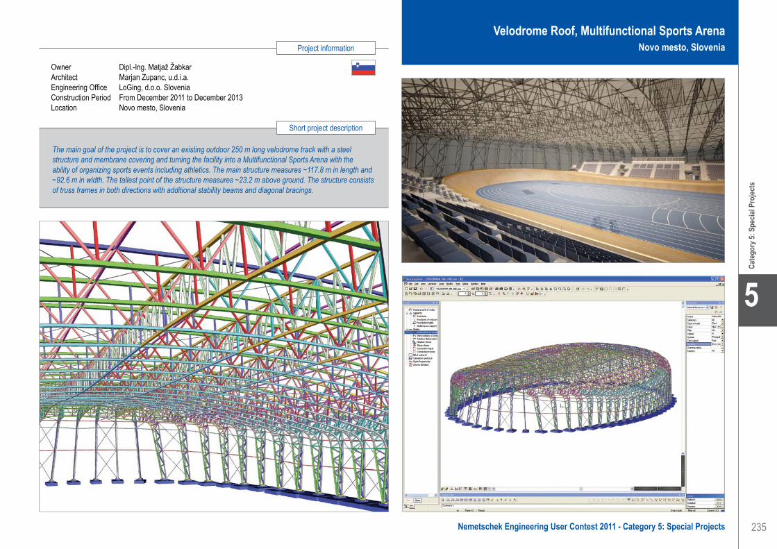
235
Project information
Short project description
Nemetschek Engineering User Contest 2011 - Category 5: Special Projects
Cate
gory
5: S
pecia
l Pro
jects
5
LoGing, d.o.o., Novo mesto. . . . . . . . . . . . . . . . . . . . . . . . . . . . . Velodrome Roof, Multifunctional Sports Arena - Novo mesto, Slovenia
Velodrome Roof, Multifunctional Sports ArenaNovo mesto, Slovenia
The main goal of the project is to cover an existing outdoor 250 m long velodrome track with a steel structure and membrane covering and turning the facility into a Multifunctional Sports Arena with the ability of organizing sports events including athletics. The main structure measures ~117.8 m in length and ~92.6 m in width. The tallest point of the structure measures ~23.2 m above ground. The structure consists of truss frames in both directions with additional stability beams and diagonal bracings.
Owner Dipl.-Ing. Matjaž ŽabkarArchitect Marjan Zupanc, u.d.i.a.Engineering Office LoGing, d.o.o. SloveniaConstruction Period From December 2011 to December 2013Location Novo mesto, Slovenia

236
5
Cate
gory
5: S
pecia
l Pro
jects
Software: Scia Engineer
MovaresContact Hans van LintAddress Postbus 2855 3500 GW Utrecht, The NetherlandsPhone +31 30 2655298Email [email protected] www.movares.nl
Platform Roofs and Footbridge in Central Station - Arnhem, The Netherlands
The station area in Arnhem will go through a drastic metamorphosis in the coming years.A new railway station will be built and also the track layout will be radically renewed.
To increase the capacity and reliability, the station will be extended; an extra platform and dive-under will be constructed.The new situation will be advantageous for the trains from the directions Utrecht and Nijmegen which are simultaneously entering the Arnhem station.Beside these radical changes in the station area there is also foreseen a complete renewal of the platform covering as well as a skywalk across the railway tracks. The current platform covering structure dates from the 50’s and no longer meets the present requirements.
UNStudioThe internationally operating architects of UNStudio designed a futuristic structure supported by an inclined column structure.The platform covering and footbridge shape a fluid intermingling entity.
Oval skylights in the roof made of Freeformglass® are designed to maximize daylight on the platform; the remaining part of the roof is lined with aluminium composite panels.
Movares developed, in close collaboration with the architect, the challenging design into an economical and reliable structure without compromising the core values of the architectural design.
Platform coveringThe most notable construction elements of the platform covering structure are the inclined columns. These columns join at platform level in such way that they can be used as a seat.
As the columns are box sections, composed of welded cut sheet, an installation shaft to keep the drainage pipes and lines out of sight could easily be provided.
The platform covering is carried by two main girders with a span of twenty meters.These beams are concealed in the lining of the hood and are made of standard rolled sections.
The large span is possible because the beam is supported against lateral torsional buckling by a link to the roof girders.These roof girders consist of straight IPE sections and curved box girders, where the latter, relatively expensive, are required only at the skylight locations.
The location of the skylight is chosen to increase transparency in the covering; the girders implemented alternating high and low tube sections (180 x 80 and 80 x 80, respectively). The weak low section is then determined by means of a constructive channel supported by a high section.
SkywalkThe inclined columns are the most remarkable elements in the structural design of the skywalk.The columns are clamped at roof level in heavy HEA sections (HEA500 and above).
In this way rigid table-shaped portals are established, strengthening the structure and providing adequate stability.
The heavy gantry beams are arranged at roof level, resulting into a slender floor structure.
Using Scia EngineerThe design of the steel structure with its inclined columns and curved beams is geometrically complex. A 3D analysis was necessary to get a clear picture of the structural behaviour of the buildings. The architect supplied the building layout and its dimensions. Consequently this design was digitally scanned straight into Scia Engineer.
The structure is divided into more or less independent parts. Of these components, several computational models were created. Models ranging from designs made only for the main structure to detailed models which were also used for designing secondary steelwork. The models of the main support structure are used to get insight into the overall load transfer and deformations, the more elaborate models are used as input for the detailed engineering.
(Copyright visuals: UNStudio)
From concept to completionMovares is an engineering consultancy providing solutions in the fields of mobility, infrastructure, building and spatial planning. Usability, future value and sustainability play a major role in the designs we produce and the advice we give. We contribute to accessibility through our unique combination of expertise. With some 1.400 members in their professional staff, Movares operates throughout Europe and has offices in the Netherlands, Germany and Poland.
Giving shape to mobilityInfrastructure is the backbone of development, both for the society and for economy. From the initial studies and the earliest planning phases to the design and execution of projects and on through to management and maintenance. Movares plays an active role throughout the entire consulting and engineering process. Our combination of knowledge, expertise and innovativity is summed up in our motto: ‘Giving shape to mobility’.
Movares. . . . . . . . . . . . . . . . . . . . . . . . . . . . . . . . . . . . . . . . . . . . Platform Roofs and Footbridge in Central Station - Arnhem, The Netherlands

237
Project information
Short project description
Nemetschek Engineering User Contest 2011 - Category 5: Special Projects
Cate
gory
5: S
pecia
l Pro
jects
5
Owner ProRailArchitect UNStudioGeneral Contractor BAM/DURA and Buiting StaalbouwEngineering Office Movares Nederland B.V.Construction Period From July 2010 to September 2011Location Arnhem, The Netherlands
The station area in the city of Arnhem will be transformed dramatically during the next few years. As passenger numbers will continue to grow, the railway infrastructure is being substantially revitalized. On the train station a new 4th platform will be added and all current platform roofs and the footbridge will be replaced. UNStudio made a futuristic design for new platform roofs and a fully integrated footbridge. In cooperation with UNStudio, Movares elaborated the design into an economic and solid steel structure.
Platform Roofs and Footbridge in Central StationArnhem, The Netherlands
Movares. . . . . . . . . . . . . . . . . . . . . . . . . . . . . . . . . . . . . . . . . . . . Platform Roofs and Footbridge in Central Station - Arnhem, The Netherlands

238
5
Cate
gory
5: S
pecia
l Pro
jects
Nuvia Travaux SpéciauxContact Antoine Piroux, Micaël ConnessonAddress 92 Cours Vitton 69006 Lyon, FrancePhone +33 4 72144490Email [email protected]
Cable Cutting Tool in a Nuclear Environment - Creys-Malville, France
Superphénix or SPX was a nuclear power station on the Rhône River in the village of Creys-Malville in France, close to the border with Switzerland. It was a fast neutron reactor, it halted electricity production in 1996 and was closed as a commercial plant in 1997.
Nuvia Travaux Spéciaux, in the framework of the decommissioning of Superphénix, is in charge of the decommissioning of the halls between the reactor building and the steam generators.
Nuvia Travaux Spéciaux has its own in-house design office and thus develops special equipment dedicated to its sites.
Design of the cutting toolsOne of the biggest operations in the decommissioning of these halls is the cutting of large steel pipes with the dimensions: diameter 700 and 1.000.
The problems are various.As the pipes were used to carry sodium, it is forbidden to cut them with tools like plasma (high temperature) as it can lead to a sodium fire. Moreover, water cooling is
prohibited: sodium explodes when it comes in contact with water. The technology chosen was the diamond cable cutting method.
Another constraint is to adapt to the highly congested environment of the halls in order to perform vertical, horizontal and even slanted cuts. The design is thus centred on the cylindrical form of the pipes. Moreover, the equipment must be transportable by hand as no handling tool is available in the cutting area.
Cutting frameThe frame dimensions are 2.2 x 1.3 x 0.65 meter. It is made of independent hollow beams which are prestrend around the pipe by means of two tie rods. A double ring is then set up on the frame.
The cutting process is run by a set of movable pulley blocks which enable to set up the diamond cable in the proper direction, according to the cutting configuration.
The tie rods are tightened up to 2.200 daN tension. The cable tension is about 180 daN, meaning a maximum force per pulley of 360 daN.
Scia EngineerScia Engineer allowed very accurate modelling of the frame thanks to beam and shell elements.
In this way it was possible to analyse the behaviour of the double ring and the interactions between the beam elements and the shell elements.
It helped us to design the structure submitted to the different external forces (maximum displacement, displacement area, most loaded elements).
It also enabled us to check that there wasn’t any slippage of the frame on the pipe.
Thanks to Scia Engineer, different cutting configurations could be tested easily and rapidly and the influence of the position of pulleys on the structures could be observed.
Initially the nuclear division of Freyssinet, Nuvia Travaux Spéciaux became an entity within Nuvia in 2008 (Nuvia is the brand name for Soletanche Freyssinet’s nuclear division). It is specialized in construction, maintenance, decommissioning and management of complex projects on nuclear sites.NTS is the heiress of all the know-how and experience acquired over 50 years on construction projects of French EDF reactor buildings. Today NTS responds to all types of problems on the civil and military nuclear facility in design, engineering and structural works.
Nuvia Travaux Spéciaux has developed expertise in:• Structural engineering and design.• Structural accessories and Interfaces Civil /
Mechanical engineering (earthquake resistant devices, prestressing devices, active or passive anchors, etc.)
• Structural repair and reinforcement (treatment of cracks, use of the Foreva® TFC, etc.)
• Structural cutting and decommissioning (cable saws, remotely-operated tools, etc.)
Software: Scia Engineer
Nuvia Travaux Spéciaux . . . . . . . . . . . . . . . . . . . . . . . . . . . . . . . Cable Cutting Tool in a Nuclear Environment - Creys-Malville, France

239
Project information
Short project description
Nemetschek Engineering User Contest 2011 - Category 5: Special Projects
Cate
gory
5: S
pecia
l Pro
jects
5
Owner EDF / CIDENArchitect Nuvia Travaux SpéciauxGeneral Contractor Nuvia (Nuvia Travaux Spéciaux / Essor)Engineering Office Nuvia Travaux SpéciauxConstruction Period From January 2010 to January 2013Location Creys-Malville, France
This project is a part of the decommissioning of Superphénix, a nuclear power station in Creys-Malville, France. It was closed as a commercial plant in 1997. Nuvia Travaux Spéciaux is in charge of the dismantling of the halls. One of the biggest operations in the decommissioning of these halls is the cutting of large steel pipes (diameter 700 and 1.000). The problems are various and the cutting is dangerous due to the congested environment (e.g. the pipes were used to carry sodium). The chosen technology is the diamond cable cutting method.
Cable Cutting Tool in a Nuclear EnvironmentCreys-Malville, France
Nuvia Travaux Spéciaux . . . . . . . . . . . . . . . . . . . . . . . . . . . . . . . Cable Cutting Tool in a Nuclear Environment - Creys-Malville, France

240
5
Cate
gory
5: S
pecia
l Pro
jects
Software: Allplan Engineering
Infoturm - Flughafen Berlin Brandenburg International - Schönefeld, Germany
TurmDen zentral angeordneten tragenden Kern des 32 m hohen Aussichtsturms bildet im Inneren ein Stahlbeton-hohlschaft mit 3 m Kreisdurchmesser. Dieser ist in ein 8 x 8 m großes Einzelfundament eingespannt, für dessen Abmessung der Kippnachweis und die hier geforderte maximale Exzentrizität von b/3 maßgebend wurde. Es wurden Berechnungen für Grundbruch sowie Setzungen durchgeführt.
Der Stahlbetonschaft dient mit dem innen liegenden Aufzug und der außen umlaufenden Stahlwendeltreppe der Erschließung der beiden Aussichtsplattformen. Als Teil des Gesamttragwerks übernimmt er die Funktion des im Wesentlichen auf Druck und Biegung beanspruchten Pfostens, von dem die auf Zug beanspruchte Gebäudehülle über die Plattformringe abgehängt wird. Die Zugkräfte, insbesondere aus der Vorspannung der Membranfassade, mit denen die wind-induzierten Verformungen klein gehalten werden sollten, waren dabei so groß, dass mehrere Abstützungen über die Turmhöhe an den Stahlbetonschaft notwendig wurden. Bei der Bemessung war auch die Schwingungsanfälligkeit entsprechend der Vorgaben eines Windgutachtens zu berücksichtigen.
Die Fassade ist so um den Turm angeordnet, dass sich im Grundriss Dreiecke ergeben, die von einem Geschoss zum nächsten fortlaufend zueinander verdreht sind. In jeder Ebene laufen außen dreiseitig Stahlprofile entlang, an denen geschossweise die Fassadenfolie geklemmt und gespannt wird. Die Kantenlängen werden in den Ebenen von unten nach oben von ca. 11 bis ca. 16 m kontinuierlich länger, mit der eine „rockartige“ Aufweitung der Hülle erzielt wird.
Es sind insgesamt zehn Ebenen über dem Boden vorhanden, deren vertikaler Abstand ca. 3 m, beträgt.
Die obersten beiden der insgesamt zehn Ebenen dienen als Aussichtsplattformen. Sie sind untereinander durch am Rand angeordnete Pfosten und Diagonalen in der gedachten Wandfläche der zueinander verdrehten Ebene verbunden. Über die an die Pfosten anschließenden Abstrebungen erfolgt die Ableitung der vertikalen und die Umlenkung der horizontalen Kräfte. Zur Stabilisierung der Fassadenunterkonstruktion in
den einzelnen Ebenen werden die außen liegenden Profile, die im Grundriss die Kanten eines Dreiecks bilden, etwa in den Drittelspunkten hin zum Betonschaft abgestützt. Vereinzelt waren die horizontal liegenden Abstützungen räumlich auszuwechseln, um den Freiraum für die Treppen nicht zu behindern.
Der Boden der beiden oberen Aussichtsplattformen besteht aus Furnierschichtholzplatten, die auf einem Rost aus Stahlträgern liegen, der am oberen Ende des Schaftes über Stahlabstrebungen abgehängt ist.
Die äußere Hülle des Turmes wird durch eine Folien-Membran-Fassade gebildet, die von den oberen Plattformen abgehängt und über horizontale Stäbe auf Abstand zum Kern gehalten werden. Im Grundriss wird diese Membranhülle je Ebene von den im Dreieck angeordneten Stahlrahmen aufgespannt. Ihre jeweils um 6° gedrehte Anordnung bewirkt die so charakteristische „verdrillte“ äußere Form des Turmes.
PavillonNeben dem Turm wird zusätzlich ein eingeschossiger Pavillon als Besucherzentrum errichtet. Der Pavillon wird als Stahlbau über einer nicht-tragenden Bodenplatte mit in Streifenfundamente eingespannten Stahlstützen und darüber verlaufenden Haupt- und Nebenträgern errichtet. Das Dach wird durch eine Furnierschichtholz-Platte gebildet und ist nur zu Wartungszwecken betretbar. Die 1.8 t Gesamtgewicht des ebenfalls auf dem Dach des Besucherpavillons stehenden Klimagerätes werden von den Stahlträgern abgetragen. Die Aussteifung des Pavillons erfolgt über die Einspannung der Stahlstützen. Im Dach ist zur Kopplung der Nebenträger ein Aussteifungsverband angeordnet.
Einige ZiffernBaukosten: ca. 1.6 Mio €Größe Infoturm: 2.720 m³ BRI, 343 m² BGF
Sailer Stepan und Partner GmbH . . . . . . . . . . . . . . . . . . . . . . . . Berlin-Brandenburg Airport InfoTower - Schönefeld, Germany
Das Ingenieurbüro Sailer Stepan und Partner GmbH wurde 1954 gegründet. Seither erbringen wir vielfältige und anspruchsvolle Planungsleistungen auf höchstem Niveau.
Unsere Tätigkeit deckt alle Grundleistungen der HOAI und nahezu alle besonderen Leistungen ab. Sie erstreckt sich auf die Planung von Neubauten, Umbauten und denkmalgeschützter Bauwerke, sowie auf Gutachten und Machbarkeitsstudien.
Die Bearbeitung eines Wanddurchbruches ist ebenso Bestandteil unseres Leistungsspektrums
wie die der Tragkonstruktion eines Groß-Bauvorhabens.
Unsere Zielsetzung ist die Entwicklung, Planung und Berechnung optimierter Tragwerke durch frühzeitige und umfassende Beratung in Abstimmung mit den Planungsbeteiligten. Architektonischer Anspruch, Wirtschaftlichkeit, Funktionalität und Innovation sind wesentliche Kriterien unserer Planung.
Sailer Stepan und Partner GmbHContact Dr. Kurt StepanAddress Ingolstädter Straße 20 80807 München, GermanyPhone +49 893509040Email [email protected] www.ssp-muc.com

241
Project information
Short project description
Nemetschek Engineering User Contest 2011 - Category 5: Special Projects
Cate
gory
5: S
pecia
l Pro
jects
5
Owner Flughafen Berlin-Schönefeld GmbHArchitect Kusus + Kusus ArchitektenGeneral Contractor Kusus + Kusus ArchitektenEngineering Office Sailer Stepan und Partner GmbHConstruction Period From September 2006 to November 2007Location Berlin, Germany
This project is about the new Info Tower of Berlin-Brandenburg International Airport (BBI-Infotower).The 32 m tall viewing tower has a 3 m diameter reinforced concrete core around a lift shaft. An external spiral staircase leads to two cantilevering viewing platforms. The core is clad in a fabric membrane which is tensioned over a series of steel frames and is hung from the viewing platforms. The steel frames are a series of equilateral triangles, each rotated 6° from its neighbor, producing the characteristic shape of the tower. The adjacent visiting center has a steel frame and is also clad with a fabric.
Berlin-Brandenburg Airport Info TowerSchönefeld, Germany
Sailer Stepan und Partner GmbH . . . . . . . . . . . . . . . . . . . . . . . . Berlin-Brandenburg Airport InfoTower - Schönefeld, Germany

242
5
Cate
gory
5: S
pecia
l Pro
jects
Haltestellenüberdachung Münchner Freiheit - München, Deutschland
Darstellung des ProjektesFür die Überdachung der Bus- und Straßenbahn-haltestelle an der Münchner Freiheit wurde aufbauend auf den architektonischen und geometrischen Vorgaben aus dem Entwurf von OX2 Architekten sowie der Entscheidung des Bauherrn, die Dachkonstruktion weder in Kunststoff noch in Leichtbeton umzusetzen, das gesamte Dach als geschweißte Stahlkonstruktion geplant.
Der Grundriss des Daches besteht aus einem Dreieck mit ausgerundeten Ecken und den Hauptabmessungen von ca. 73 x 31.5 m. Es ist auf insgesamt 18 Stützen-gruppen zu je drei Stützen auf der darunterliegenden U-Bahnstation aufgeständert. Der direkte Anschluss der Stützengruppen erfolgt über ein Stahlbetonfundament, das auf der U-Bahndecke verankert wird.
Die Dachfläche wird durch ein räumlich konvex und konkav gekrümmtes Flächentragwerk gebildet, das in den inneren frei spannenden Bereichen vorwiegend über günstige Gewölbewirkungen, d.h. Druckkräfte in der Dachfläche, abträgt. Aufgrund der unsymmetrischen Anordnung und wechselnden Höhenlage der Auflager, ergeben sich jedoch Gewölbe verschiedenster Höhen, die sich teilweise überlagern und ineinander verschneiden. Die Dachfläche ruht auf insgesamt 18 Stützengruppen. Jede der Gruppen besteht aus drei sehr schlanken Stielen, die sich nach oben kelchförmig aufweiten. Am Dachansatz vereinen sie sich zu einem geschlossenen Ring und tauchen fließend in die Dachfläche ein. Die Auflösung der 18 Auflagerpunkte in jeweils 3 Stützensegmente bewirkt, dass sobald sich die Dachfläche in die drei Stützensegmente aufteilt, der horizontale Lasttransport ausschließlich über die Biegetragfähigkeit der Stützenkelche erfolgt und Gewölbewirkungen nicht mehr zum Tragen kommen. Am direkten Übergang der Stützenkelche wird ein umlaufender torsionssteifer Kastenquerschnitt angeordnet, der Einspannungen aus der Dachfläche sammelt, über die Ringwirkung glättet und den Eintrag von Biegemomenten in die dünnen Stützenstiele verringert.
An den Rändern, insbesondere auf der der Leopoldstrasse zugewandten Seite, kragt die Dachfläche weit aus. Hier erfolgt die Lastabtragung
nahezu ausschließlich über die Biegetragfähigkeit der Konstruktion.
Die gesamte Tragkonstruktion baut auf dünnen, der Dachkontur folgend in wechselnden Radien gebogenen Blechen auf. Die Blechstärke beträgt t = 10 mm. In Bereichen, in denen die Lastabtragung über Gewölbe-wirkungen erfolgt, werden diese lediglich mit flachen Rippen ausgesteift. Diese verhindern ein lokales Ausweichen (Beulen) der dünnen Blechschale. In Bereichen mit Biegebeanspruchungen wird das Blech durch aufgesetzte Tragrippen verstärkt. In Einzelfällen laufen die Rippen bis zum Dachrand bzw. bis zu ~ 7 m in die Dachfläche.
Die Berechnung der Tragkonstruktion erfolgt nach der Finiten-Element-Methode.Im Gegensatz zu einer Stahlbetonkonstruktion ist zur Berechnung der Stahlkonstruktion ein sehr engmaschiges Knotennetz erforderlich. Für die Anordnung von gradlinigen Rippen muss die Knotenstruktur möglichst den Tragrippen folgen.
Die gesamte Netzstruktur wurde so aufgebaut, dass die statisch erforderlichen Haupttragrippen geradlinig berücksichtigt werden können. D.h. in der Berechnung werden die für Standsicherheit der Gesamtstruktur erforderlichen Tragrippen abgebildet. Zusätzliche konstruktive Rippen oder für das örtliche Tragverhalten notwendige Rippen werden nur berücksichtigt, sofern es aufgrund der Nutzstruktur sinnvoll erscheint. Für nicht berücksichtigte Rippen wird im Lastfall “Dachaufbau” ein entsprechender Lastanteil berücksichtigt.
Einige ZiffernGesamtbaukosten: ca. 3.7 Mio. €Deckenspannweiten: bis 15 m
Software: Allplan Engineering
Sailer Stepan und Partner GmbH . . . . . . . . . . . . . . . . . . . . . . . . Canopy for Tram-terminus Münchner Freiheit - Munich, Germany
Das Ingenieurbüro Sailer Stepan und Partner GmbH wurde 1954 gegründet. Seither erbringen wir vielfältige und anspruchsvolle Planungsleistungen auf höchstem Niveau.
Unsere Tätigkeit deckt alle Grundleistungen der HOAI und nahezu alle besonderen Leistungen ab. Sie erstreckt sich auf die Planung von Neubauten, Umbauten und denkmalgeschützter Bauwerke, sowie auf Gutachten und Machbarkeitsstudien.
Die Bearbeitung eines Wanddurchbruches ist ebenso Bestandteil unseres Leistungsspektrums
wie die der Tragkonstruktion eines Groß-Bauvorhabens.
Unsere Zielsetzung ist die Entwicklung, Planung und Berechnung optimierter Tragwerke durch frühzeitige und umfassende Beratung in Abstimmung mit den Planungsbeteiligten. Architektonischer Anspruch, Wirtschaftlichkeit, Funktionalität und Innovation sind wesentliche Kriterien unserer Planung.
Sailer Stepan und Partner GmbHContact Thomas WinklerAddress Ingolstädter Straße 20 80807 München, GermanyPhone +49 893509040Email [email protected] www.ssp-muc.com

243
Short project description
Nemetschek Engineering User Contest 2011 - Category 5: Special Projects
Cate
gory
5: S
pecia
l Pro
jects
5
Project informationOwner Stadtwerke München GmbHArchitect Reichert Pranschke Maluche Architekten GmbHGeneral Contractor SWM Services GmbHEngineering Office Sailer Stepan und Partner GmbHConstruction Period From August 2009 to December 2009Location Munich, Germany
The new canopy roof of the tram terminus at Münchner Freiheit forms a new architectural highlight along the 3 km route from Münchner Freiheit to Parkstadt Schwabing. Structural engineers Sailer Stepan and Partners designed the 1.500 m² canopy as a steel double curved grid shell with 18 freestanding columns. An intense design process has determined the choice of materials, the optimized shape of the roof and the restricted load transfer to the existing underlying structure of the subway station.
Canopy for Tram Terminus Münchner FreiheitMunich, Germany
Sailer Stepan und Partner GmbH . . . . . . . . . . . . . . . . . . . . . . . . Canopy for Tram-terminus Münchner Freiheit - Munich, Germany

244
5
Cate
gory
5: S
pecia
l Pro
jects
Openbaar Vervoer Terminal - Rotterdam, Nederland
Het project Openbaar Vervoer Terminal Rotterdam Centraal maakt onderdeel uit van het Nieuwe Sleutelproject (NSP) Rotterdam Centraal en wordt gerealiseerd ter plaatse van het bestaande station Rotterdam Centraal. De sporen en bijhorende railgerelateerde voorzieningen worden aangepast. Er wordt een nieuwe passage als loopverbinding tussen de sporen, de hallen en het maaiveld, samen met twee nieuwe stationshallen en een nieuwe sporenkap gerealiseerd.
Geometrie van de sporenkapDe perronoverkapping van Rotterdam Centraal heeft een lengte van ca. 250 m, een breedte van ca.155 m en een maximale hoogte van 17 m. Het betreft een vrijwel volledig transparante overkapping, gedragen door een staalconstructie in combinatie met een houtconstructie. De hoofdconstructie van de Sporenkap bestaat uit de volgende onderdelen:• Y vormige stalen spantkolommen op de perrons,
bestaande uit samengelaste kokerprofielen met variabele hoogte en breedte.
• Twee stalen spagaatkolommen (omgekeerde Y) onder de Y kolommen ter plaatse van de vides in de perrons, bestaande uit samengelaste kokerprofielen met variabele hoogte en breedte.
• Rechthoekige stalen spantliggers met een variabele breedte en verspringende onder-en bovenflens.
StabiliteitIn de lengterichting (O-W) van de overkapping wordt de stabiliteit verkregen door het toepassen van 6 stuks langspanten. Deze worden” semi-scharnierend” (rotatieveer) verbonden met de fundering. In de dwarsrichting (N-Z) van de overkapping wordt de stabiliteit verkregen door ingeklemde kolomvoeten van de langspanten.
Uitdagingen in de berekening• Opsporen en berekenen van de meest nadelige
sectie in de Y kolommen met een variabele breedte en hoogte, rekening houdende met globaal en locaal plooien (kokerprofielen klasse 4) van de plaatelementen.
• Bepalen van de correcte kniklengte van de Y kolommen (stabiliteit en 2de orde berekening).
• Bepalen van de correcte veerstijfheid van de combinatie fundering en kolomvoetverbinding.
Aanpak voor de berekening van deze uitdagingenIn een 3D-stavenmodel zijn aan de hand van de profielcontrole NEN6770 en NEN6771 in EPW de meest nadelige posities, meest nadelige fase (situatie tijdens de oplevering van de overkapping, de toekomstige situatie of de verschillende bouwfasen) en meest nadelige belastingscombinatie opgespoord. De plooigevoelige profielsecties (klasse 4) zijn eveneens in een 3D-platenmodel gecontroleerd dat geïntegreerd is in het 3D-stavenmodel om de correcte krachtsinleiding te bekomen.
De staaf- en 3D-plaatmodellen zijn niet-lineair doorgerekend met effecten van “enkel trek staven” en “2de orde berekening” zonder het invoeren van geometrische imperfecties (scheefstand of vooruitbuiging). Deze geometrische imperfecties zijn in rekening gebracht bij de bepaling van de juiste kniklengtes en zijn verwerkt in de staalcontrole volgens NEN6770/6771. In feite is een 2de orde berekening niet vereist aangezien de kritische last groter is dan 10 (stabiliteitscontrole). De juiste kniklengte is bepaald aan de hand van de stabiliteitsberekening in Esa-Prima Win en de bepaling van de correcte kleinste kritische last. Hiervoor zijn enkel de relevante onderdelen in het model behouden.
In alle modellen zijn rotatieveren ingegeven voor de Y kolommen in de O-W richting en een inklemming in de N-Z richting. De rotatieveerstijfheid is bepaald aan de hand van een 3D-platenmodel van de kolomvoet, waarbij een verende bedding is ingegeven onder de voetplaat die enkel druk kan opnemen en bouten gemodelleerd zijn door ronde staven die enkel trek kunnen opnemen. Als eindcontrole is er nagekeken of de vervormingen in het staven- en platenmodel overeenkomen.
SBE nv is een vitaal en dynamisch studie-, teken- en ingenieursbureau, gevestigd te Sint-Niklaas nabij de Antwerpse haven.
Het bureau heeft zich gedurende de laatste 30 jaar geprofileerd als een studie- en adviesbureau gespecialiseerd in havenconstructies, burgerlijk bouwkunde, geotechnische problemen, staalstructuren en funderingstechnieken
Met meer dan 30 jaar ervaring in de verschillende domeinen van de bouwkunde, en vooral dan op het gebied van grote infrastructurele projecten,
zijn de projectingenieurs de leidende kracht voor een jong en dynamisch team dat met een grote gedrevenheid de meest uiteenlopende opdrachten aanpakt.
De studieopdrachten worden uitgewerkt met de nadruk op kwaliteit en uitvoerbaarheid, doch steeds rekening houdend met de financiële en economische haalbaarheid, met referenties in Europa, Oekraïne, Korea, Nigeria, Panama, etc.
SBE nvContact Sven Barrez, Guy Van Nuffel, Wim De Nutte,
Lucrèse VermaereAddress Slachthuisstraat 71 9100 Sint-Niklaas, BelgiumPhone +32 3 777 95 19Email [email protected] www.sbe.be
Software: ESA-Prima Win, Scia Engineer
SBE nv. . . . . . . . . . . . . . . . . . . . . . . . . . . . . . . . . . . . . . . . . . . . . Public Transport Terminal - Rotterdam, The Netherlands

245
Project information
Short project description
Nemetschek Engineering User Contest 2011 - Category 5: Special Projects
Cate
gory
5: S
pecia
l Pro
jects
5
This project is about the public transportation terminal of the Rotterdam Central Station. This building has a length of 250 m, a width of 155 m and a maximum height of 17 m. It is a transparent construction with a glass roof, supported on wooden beams and a steel mainframe of Y columns and beams. The legs of the column have a rectangular variable cross section. The difficulties of this project were: the determination of the most critical section in the structure, taken into account the local buckling of the welded plates, the correct buckling length of the Y columns with variable cross-section and the correct rotation stiffness of the column base.
Owner NS Nederlandse SpoorwegenArchitect Jan BenthemGeneral Contractor Mobilis B.V. TBI InfraEngineering Office SBE nvConstruction Period From September 2009 to December 2012Location Rotterdam, The Netherlands
Public Transport TerminalRotterdam, The Netherlands
SBE nv. . . . . . . . . . . . . . . . . . . . . . . . . . . . . . . . . . . . . . . . . . . . . Public Transport Terminal - Rotterdam, The Netherlands

246
5
Cate
gory
5: S
pecia
l Pro
jects
Software: Scia Engineer
Skála & Vít s.r.o.Contact Vladimír Ferkl, Zdeněk DoležalAddress Opletalova 328 50003 Hradec Králové, Czech RepublicPhone +420 604230286Email [email protected] www.skala-vit.cz
Zlín Congress Centre - Zlín, Czech Republic
Construction descriptionThe steel construction of the Zlín Congress Centre consists of two steel arches, leaning out from each other and strained in the direction of the longer axis of the building’s oval and is made of seamless steel tubes Ø 610 mm. The main arches are supported by sleeve bearings on the perimeter attic. The main supports (space diagonals) are set on the perimeter walls of the hall. The arches are tied by lattice pipe braces. The arches support space triangle ribs serving as space piping lattice with bent bottom passes and the top pass overlapping the building’s horizontal projection. Prestressed ties are dropped down to the ground surface. Slant surfaces of the ribs, whose horizontal projections are triangular but making up distorted surfaces, are covered with expanded aluminum sheets. The triangular faces of the overhanging elements are covered in the same way.
The steel construction of the restaurant consists of 24 seamless piping half-arch ribs, where the guiding curve is made up of four arches composed into a single unit. On one end, the ribs are set on a concrete sill bearing. On the other end, they are mounted to a central ring set on the inner support and, at the same time, serve as support for the non-transparent part of the roof. The ribs are strutted by pipes mounted at two levels. Three fields of the steel constructions are wind-protected using a system of ties. The supporting structure elements have been designed and evaluated for ‘15 minute’ resistance to fire.
The steel construction of the hanging lighted façade consists of seamless pipes connected to one unit. Between the façade columns, panels made of glass block panels with steel rims are inserted. The panels are mounted on short brackets welded to columns and screwed to the bushes fitted on the rims. Horizontally, the façade is divided into sections, each containing two fields with three columns composed to the V-shape. On the floor level, the façade leans against the perimeter concrete wall, always at the column location. The supports are fitted with gangways, made of square rods and grates, located on three levels corresponding to the building’s floors. The gangways serve for façade maintenance or repairs.
Construction solutionDue to spatial complexity of the constructional steelwork during the first phase we decided to create a spatial structural model with exact geometry projection. The structural model was created in Scia Engineer, using the comfortable import of the 3D geometry from DWG. The ease of the import became evident mainly during a change to geometry, which was done four times just during the creation of the project. The export allows using various filters, e.g. it is possible to import just some of the levels or entities and the current import immediately displays in the preview window. Thus, it was possible to add partial changes in one geometry to a new level and enter them into the structural system also into a special level as lines or arches. The created geometry was then adjusted just by relocating the perimeter element nodes. Here, the advantage of relative nodes showed - they retain their relative position on the element. Another aspect improving effectiveness is arch elements, which are defined by three nodes and are distributed to straight sections only when creating the grid for calculation. Due to the aesthetic function of the construction without continual solid surfaces the temperature load was a decisive factor. We designed the most of support points as sliding to prevent too large powers affecting the concrete structure finished with a 250 mm thick attic.
We designed the restaurant and façade structures in independent computational models. The main curve of the restaurant’s cross-link was again created from a DWG file and imported to the Scia Engineer system. The original elliptical shape was replaced by composing two arches into one curve.
Regarding the façade, we dealt just with the largest typical fields.
The Skála & Vít, s.r.o. design and construction office was registered in 1998. The company specializes in building constructional steelwork and shelling.Our steelwork projects comprise mainly public buildings, logistics and warehouse centres, large retail stores, industrial and agricultural premises including technological constructions.
We prepare and process projects for all project stages, e.g. building permission projects, implementation projects including workshop or production documentation using latest software.
At present we focus on projecting and proving resistance to fire via static calculation of the constructional steelwork, where we emphasize the right construction design methodology and cooperation between all involved professionals. We try to share our approach with the expert public at various seminars which we hold all across the Czech Republic.
In 2002, the company was certified according to the ČSN EN ISO 9001:2001 standard, or ČSN EN ISO 9001:2009 and is member of the Czech Constructional Steelwork Association.
Skála & Vít s.r.o. . . . . . . . . . . . . . . . . . . . . . . . . . . . . . . . . . . . . . Zlín Congress Centre - Zlín, Czech Republic

247
Project information
Short project description
Nemetschek Engineering User Contest 2011 - Category 5: Special Projects
Cate
gory
5: S
pecia
l Pro
jects
5
Owner Zlín CityArchitect Prof.Ing.Arch. Eva JiřičnáGeneral Contractor PSG international and Metrostav, a.s.Engineering Office Skála & Vít, s.r.o.Construction Period From June 2009 to October 2010Location Zlín, Czech Republic
The Zlín Congress Centre is a steel construction divided into several units. The main part is the roofing, which has both an aesthetic and covering function. The horizontal projection is an oval shape. The primary and secondary axes of the oval are 70.5 m and 42.3 m long. The roof construction camber is 7.5 m. This spanning is overcome using arches and prestressed ribs made of circular cross-section pipes. The ribs are anchored using ties attached to the building foundations. Other parts were the roofing of the steel structure of the restaurant and the hanging façade. The restaurant has a circular platform of 16 m Ø and 4 m height.
Zlín Congress CentreZlín, Czech Republic
Skála & Vít s.r.o. . . . . . . . . . . . . . . . . . . . . . . . . . . . . . . . . . . . . . Zlín Congress Centre - Zlín, Czech Republic
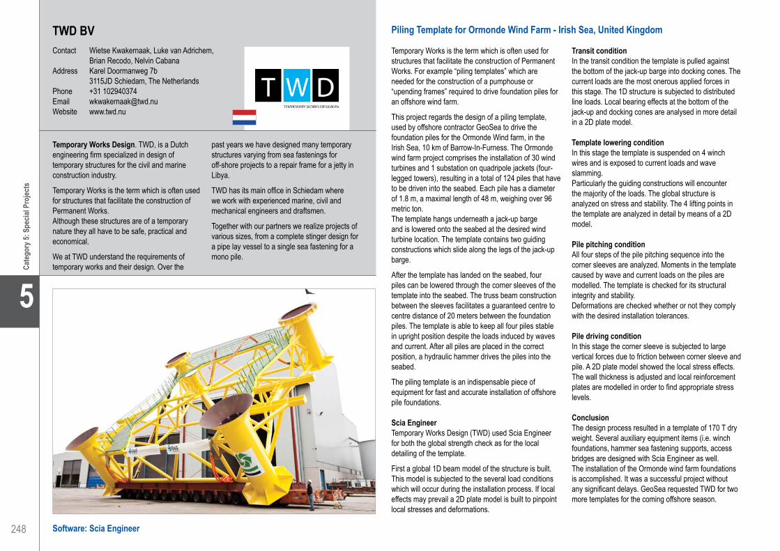
248
5
Cate
gory
5: S
pecia
l Pro
jects
TWD BVContact Wietse Kwakernaak, Luke van Adrichem,
Brian Recodo, Nelvin CabanaAddress Karel Doormanweg 7b 3115JD Schiedam, The NetherlandsPhone +31 102940374Email [email protected] www.twd.nu
Piling Template for Ormonde Wind Farm - Irish Sea, United Kingdom
Temporary Works is the term which is often used for structures that facilitate the construction of Permanent Works. For example “piling templates” which are needed for the construction of a pumphouse or “upending frames” required to drive foundation piles for an offshore wind farm.
This project regards the design of a piling template, used by offshore contractor GeoSea to drive the foundation piles for the Ormonde Wind farm, in the Irish Sea, 10 km of Barrow-In-Furness. The Ormonde wind farm project comprises the installation of 30 wind turbines and 1 substation on quadripole jackets (four-legged towers), resulting in a total of 124 piles that have to be driven into the seabed. Each pile has a diameter of 1.8 m, a maximal length of 48 m, weighing over 96 metric ton. The template hangs underneath a jack-up barge and is lowered onto the seabed at the desired wind turbine location. The template contains two guiding constructions which slide along the legs of the jack-up barge.
After the template has landed on the seabed, four piles can be lowered through the corner sleeves of the template into the seabed. The truss beam construction between the sleeves facilitates a guaranteed centre to centre distance of 20 meters between the foundation piles. The template is able to keep all four piles stable in upright position despite the loads induced by waves and current. After all piles are placed in the correct position, a hydraulic hammer drives the piles into the seabed.
The piling template is an indispensable piece of equipment for fast and accurate installation of offshore pile foundations.
Scia EngineerTemporary Works Design (TWD) used Scia Engineer for both the global strength check as for the local detailing of the template.
First a global 1D beam model of the structure is built. This model is subjected to the several load conditions which will occur during the installation process. If local effects may prevail a 2D plate model is built to pinpoint local stresses and deformations.
Transit conditionIn the transit condition the template is pulled against the bottom of the jack-up barge into docking cones. The current loads are the most onerous applied forces in this stage. The 1D structure is subjected to distributed line loads. Local bearing effects at the bottom of the jack-up and docking cones are analysed in more detail in a 2D plate model.
Template lowering conditionIn this stage the template is suspended on 4 winch wires and is exposed to current loads and wave slamming.Particularly the guiding constructions will encounter the majority of the loads. The global structure is analyzed on stress and stability. The 4 lifting points in the template are analyzed in detail by means of a 2D model.
Pile pitching conditionAll four steps of the pile pitching sequence into the corner sleeves are analyzed. Moments in the template caused by wave and current loads on the piles are modelled. The template is checked for its structural integrity and stability.Deformations are checked whether or not they comply with the desired installation tolerances.
Pile driving conditionIn this stage the corner sleeve is subjected to large vertical forces due to friction between corner sleeve and pile. A 2D plate model showed the local stress effects. The wall thickness is adjusted and local reinforcement plates are modelled in order to find appropriate stress levels.
ConclusionThe design process resulted in a template of 170 T dry weight. Several auxiliary equipment items (i.e. winch foundations, hammer sea fastening supports, access bridges are designed with Scia Engineer as well.The installation of the Ormonde wind farm foundations is accomplished. It was a successful project without any significant delays. GeoSea requested TWD for two more templates for the coming offshore season.
Temporary Works Design. TWD, is a Dutch engineering firm specialized in design of temporary structures for the civil and marine construction industry.
Temporary Works is the term which is often used for structures that facilitate the construction of Permanent Works. Although these structures are of a temporary nature they all have to be safe, practical and economical.
We at TWD understand the requirements of temporary works and their design. Over the
past years we have designed many temporary structures varying from sea fastenings for off-shore projects to a repair frame for a jetty in Libya.
TWD has its main office in Schiedam where we work with experienced marine, civil and mechanical engineers and draftsmen.
Together with our partners we realize projects of various sizes, from a complete stinger design for a pipe lay vessel to a single sea fastening for a mono pile.
Software: Scia Engineer
TWD BV. . . . . . . . . . . . . . . . . . . . . . . . . . . . . . . . . . . . . . . . . . . . Piling Frame for Ormonde Wind Farm - Irish Sea, United Kingdom

249
Project information
Short project description
Nemetschek Engineering User Contest 2011 - Category 5: Special Projects
Cate
gory
5: S
pecia
l Pro
jects
5
Owner Geosea (Belgium)General Contractor G&G International (Belgium)Engineering Office Temporary Work Design BVConstruction Period From November 2009 to April 2010Location Irish Sea, United Kingdom
The project concerns the design of a piling template for the Ormonde wind farm in the Irish Sea (UK), built by offshore contractor GeoSea. For fast and accurate installation of the foundation piles a ‘piling template’ is used. GeoSea requested Temporary Works Design to make a design for this template, from concept to detailed drawings. The strength of both the global design and local details are checked with1D and 2D models built in Scia Engineer. Several auxiliary equipment items (such as winch foundations, hammer sea fastening supports and access bridges) are designed with Scia Engineer as well.
Piling Frame for Ormonde Wind FarmIrish Sea, United Kingdom
TWD BV. . . . . . . . . . . . . . . . . . . . . . . . . . . . . . . . . . . . . . . . . . . . Piling Frame for Ormonde Wind Farm - Irish Sea, United Kingdom

250
5
Cate
gory
5: S
pecia
l Pro
jects
Software: Scia Engineer
University of Patras, Faculty of Civil EngineeringContact Marios Filippoupolitis, Fillitsa V. KarantoniAddress Dep. of Civil Engineering University of Patras 26500 Patras, GreecePhone +30 2610 997778Email [email protected] www.civil.upatras.gr
University of Patras, Faculty of Civil Engineering . . . . . . . . . . . . Monastery of Fragavilla - Amalias, Greece
Monastery of Fragavilla - Amalias, Greece
Seismic analysis of a byzantine church using pressure only finite elements and its retrofitting by steel tendons
Marios K. FilippoupolitisMSc Civil Engineer, University of Patras
Fillitsa V. KarantoniDr Civil Engineer, Department of Civil Engineering, University of Patras
Description of the structureThe byzantine church under consideration, which is called Monastery of Fragavilla, is located 2 km south-east from Amalias, in the Elis prefecture of western-Greece, one of the most seismic prone areas of Europe. It is built during the first half of the 12th century and because of its form the building is classified as a church of the type “enrolled cross with dome”.
The temple is formed by two orthogonal barrel vaults at the intersection of which is situated the cylindrical drum that supports the dome. The width of the stone masonry walls varies from 0.90 m to 0.70 m. The dome as well as the vaults are mainly made of solid bricks and have a thickness of 0.26 m.
Aim of the projectThe aim of this project is to study the application of the pressure only elements on the seismic analysis of a masonry church with complex geometry and its retrofitting by steel tendons.
Pressure only elementsPressure only elements were developed for the analysis of masonry walls, as this is a typical case of an element that can sustain only compression forces.
The calculation is based on an iterative process. In every finite element where tension is found, an orthotropy will be given in such a way that the stiffness in the direction of tension is lower, which causes that the force will find its way through the elements in the direction of pressure lines in which the element is given a higher stiffness. This iterative process continues until equilibrium is found, but never stiffness less than 5% will be given in a direction.
Seismic analysisFrom the modal analysis we obtain the first two natural periods (T1 = T2 = 0.07 sec). The design spectral acceleration Sa(T) was calculated from the Greek Seismic Code equal to 0.41g. An equivalent static analysis for eight load combinations (G±Ex ±0.30Ey and G±0.3Ex ±Ey) was performed.
Steel tendonsA pair of steel tendons of 25 mm diameter was inserted into the masonry walls at the level of the springs of the secondary vaults. The steel tendons were simulated as 1D members that can sustain only axial forces.
ResultsThe non-linear analysis depicts that the developing tensile stresses at the critical parts of the church (vaults, drum and pendentives) are higher than the tensile strength of the masonry. After the insertion of the steel tendons, confinement of the structure was achieved and the developing tensile stresses at the critical parts of the church were slightly decreased.
The role of Scia Engineer Scia Engineer proved to be a valuable partner for the simulation and analysis of the Monastery of Fragavilla.
Specifically:• The general cross section module gave us the
capability to simulate the complex geometry of the four masonry piers of the church
• The mesh generator was able to create with a great speed an excellent finite element mesh despite the complexity of the structure
• The 2D member components module of Scia Engineer made it possible to simulate the behaviour of the steel tendons inside the masonry walls
• Scia Engineer’s support team was always available when any problem occurred during this project
The Department of Civil Engineering of University of Patras was founded in 1972, consists of 35 fulltime faculty members and has an undergraduate student body of about 1.200 persons. It operates under the 5 years study program and offers the degree of Civil Engineering. It consists of three Divisions which cover the areas of Structural Engineering, Geotechnical Engineering and Hydraulic Engineering and Environmental Engineering, Transportation Engineering and Building Technology/City Planning.
The Department operates 8 Laboratories for teaching and research purposes. In addition, the Department has a Computer Centre with a large number of personal computers, which provides adequate computing facilities.
The Department is also responsible for graduate education leading to the degrees of Master of Civil Engineering and Doctor of Civil Engineering through a comprehensive graduate studies program involving graduate level courses.

251
Project information
Short project description
Nemetschek Engineering User Contest 2011 - Category 5: Special Projects
Cate
gory
5: S
pecia
l Pro
jects
5
Owner Holy Metropolis of Eleia and OleniConstruction Period First half 12th centuryLocation Amalias, Greece
Monastery of FragavillaAmalias, Greece
University of Patras, Faculty of Civil Engineering . . . . . . . . . . . . Monastery of Fragavilla - Amalias, Greece
The byzantine Monastery of Fragavilla was built during the first half of the 12th century and is classified as a church of the type “enrolled cross with dome”. The temple has survived almost undamaged over 900 years until the March 1993 Pyrgos (Greece) earthquake sequence, when it suffered severe damage to the extent that scaffolding had to be installed to prevent collapse. This project’s aim is to study the application of pressure only elements on the seismic analysis of this masonry church with complex geometry and its retrofitting by steel tendons.

252
5
Cate
gory
5: S
pecia
l Pro
jects
Baltic Arena - Danzig, Polen
Zur Fußball Europameisterschaft 2012 entsteht in Danzig die Baltic Arena. Das neue Stadion fasst 44.000 Zuschauer und wird dank seiner außergewöhnlichen Formgebung und aufwändigen Konstruktion ein neues Wahrzeichen der einstigen Hansestadt an der polnischen Ostseeküste werden.
Die Anlage erstreckt sich über eine Gesamtfläche von fast 40 Hektar. Nach der Fertigstellung wird die Arena nicht nur einen idealen Rahmen für die EM 2012 darstellen, sondern auch als Heimstadion des Fußball-Erstligisten Lechia Gdansk fungieren. In der transluzenten Fassade und der wellenförmigen Linienführung der Zuschauertribünen greift die Baltic Arena Danziger Traditionen wie den Bernsteinhandel oder den Schiffbau auf.
Das Büro Vogel Ingenieure im Bauwesen GmbH aus Hannover wirkt als hauptverantwortlicher Tragwerksplaner an zentraler Stelle bei der Umsetzung des Großprojekts mit. Bei Ihrer Arbeit vertrauen die Vogel Ingenieure seit 20 Jahren auf die Leistungsfähigkeit von GLASER -isb cad-.
StadionkonstruktionDas Stadion ist 227 m lang, 197 m breit, 45 m hoch und hat 44.000 Besucherplätze. Die Baltic-Arena ist in neun Ebenen aufgeteilt:• Ebene 00: Technik• Ebene 01: Commercial Area, Marathontunnel,
Teamebene• Ebene 02: Promenade 1, Businessebene• Ebene 03: Loge 1• Ebene 04: Promenade 2, Loge 2• Ebene 05: Tribünenzugang, Presse• Ebene 06: Technik 2• Ebene 07: Presseplattform• Ebene 08: Sky Box
Die Stadionkonstruktion besteht aus Stahlbeton-Bindern in Fertigteilbauweise mit einem Stützenraster von max. 8.0 x 8.0 m. Auf den Bindern sind die Tribünenfertigteilelemente aufgelagert. Die Verteilerebenen werden als Ortbetonplatten erstellt. Um die Schwindeinflüsse zu minimieren, wurden in der Plattenkonstruktion Fugen im Abstand maximal 72 bis 80 m eingeplant. Die Aussteifung erfolgt über Stahlbeton-Wände bzw. horizontale Verbände und umlaufende Stahlrohre.
Die Stadiontribünen sind vollständig überdacht. Die Dachkonstruktion besteht aus 82 räumlichen spantenförmigen Stahlfachwerkbindern, die nicht horizontal mit den Betontribünen verbunden sind. Das Stadiondach stellt ein eigenständiges unabhängiges Tragwerk dar. Die Hauptbinder sind miteinander durch umlaufende Querelemente, die einen geschlossenen Ring bilden, verbunden. Die Fachwerkbinder haben einen Abstand von zirka 8.00 m. Die Höhe von der Fußebene bis zur Dachfläche beträgt ca. 45 m. Die Dachhaut besteht aus Polycarbonatplatten mit einer Aluminiumkonstruktion als Sekundärtragwerk. Das Dachtragwerk hat ein Gesamtstahlgewicht von ca. 7.000 t. Die statische Berechnung erfolgte an einem dreidimensionalen Gesamtsystem.
30 Jahre Erfahrung setzen Maßstäbe.Basierend auf unserer langjährigen Arbeit mit bewährten und innovativen Bau- und Konstruktionsarten planen und entwickeln wir wirtschaftlich und termingerecht Bauprojekte verschiedenster Art.Konstruktiv die Zukunft gestalten.Wir entwickeln, planen, berechnen und überwachen Hochbauten, Sportstätten, Industrieanlagen, Büro- und Wohnbauten, Parkhäuser usw.Unsere Neugier kennt keine Grenzen!Die Grundlage unserer täglichen Arbeit bildet die
Tragwerksplanung über alle Leistungsphasen der HOAI, bauphysikalische Nachweise in Verbindung mit kostensenkenden ökologischen Bauweisen, Baugrunduntersuchungen sowie Gründungsberatungen und Baugrundgutachten.Planen und Bauen sehen wir als Teamarbeit.Die kontinuierliche Zusammenarbeit mit Bauherrn, Architekt und Fachingenieuren ist ausschlaggebend für einen nachhaltigen Erfolg.Unser Anspruch ist, innovativ gestaltete, umweltgerechte und wirtschaftliche Baukonstruktionen zu entwickeln sowie eine terminbewusste Abwicklung zu gewährleisten.
Vogel Ingenieure im Bauwesen GmbHContact Hans-Jürgen VogelAddress Sutelstr. 23 30659 Hannover, GermanyPhone +49 511 438236-0Email [email protected] www.vogel-ing.de
Software: GLASER -isb cad-
Vogel Ingenieure im Bauwesen GmbH . . . . . . . . . . . . . . . . . . . . Baltic Arena - Gdansk, Poland

253
Project information
Short project description
Nemetschek Engineering User Contest 2011 - Category 5: Special Projects
Cate
gory
5: S
pecia
l Pro
jects
5
The Baltic Arena in Gdansk is being built for the 2012 European football championship. The stadium will be able to receive 44.000 spectators and thanks to its unique shape and sophisticated design it will become a new landmark of the city on the Polish Baltic coast.The stadium structure consists of precast reinforced concrete beams which support the precast tribune members. The distribution levels will be made up of in-situ slabs. 82 steel trusses and a ring of cross members form a unique roof structure weighing about 7.000 tons.
Owner Stadt DanzigArchitect RKW Rhode Kellermann Wawrowsky GmbH & Co. KGGeneral Contractor Alpine BauEngineering Office Vogel Ingenieure im Bauwesen GmbHConstruction Period From December 2008 to May 2011Location Gdansk, Poland
Baltic ArenaGdansk, Poland
Vogel Ingenieure im Bauwesen GmbH . . . . . . . . . . . . . . . . . . . . Baltic Arena - Gdansk, Poland

254
5
Cate
gory
5: S
pecia
l Pro
jects
Universal Scissor Component - Brussels, Belgium
Information on the projectDeployable scissor structures consist of beam elements connected by hinges, allowing them to be folded into a compact bundle for storage or transport. Subsequently, they are deployed, demonstrating a huge volume expansion. This process can be reversed, allowing re-use.
The purpose of the research aimed at designing and analyzing a new multi-configurational Universal Scissor Component. While current designs of scissor systems give an ‘ad hoc’ solution, this research provides a methodology for designing a scissor component resulting in generic structures: different geometrical domes and barrel vaults with varying spans. The Universal Scissor Component is a single and unique element in all the proposed configurations, the only difference is the position of the pivot hinge. This concept makes re-use and adaptability possible: it is well equipped to meet changing requirements.
A structural study is conducted to investigate the feasibility of the new concept.
Project approachDuring deployment no additional stresses are induced in the proposed foldable structures and the imposed loads and span are usually less than those for the fully deployed state. Therefore, the structural study concentrated on the analysis in the fully deployed configuration. In a larger construction the loads increase and the global instability becomes significant due to the scale-effect. Hence, a total detailed calculation of the largest barrel vault structure is assumed to result in a scissor component that satisfies the structural requirements in all system configurations.The study includes the geometric modelling of the structure, the determination of the symmetrical and asymmetrical load cases and the dimensioning of the Universal Scissor Component.
Structural conceptThe semi-cylindrical shape of the barrel vault consists of 11 arches formed by the USC composed in a polar configuration, which are linked together with translation USC’s creating a deployable structure.
The geometry is based on a semicircle with a radius of 8.6 m. It has a span of approximate 17 m and the structural thickness is less than 1 m. The barrel vault is an open structure in steel with neither back nor front and encloses a quite large architectural area of 308 m2.
Generally, mobile deployable structures consist of a weather protecting membrane. This dissertation however focused on the feasibility of the designed steel scissor structure, without details regarding a more accurate load transfer with a pre-tensioned membrane. Therefore 2D plate elements are introduced in the structure to form a 3D shell. The 2D elements are modelled as thin aluminium plates with an adjusted self weight to approach the self weight of a membrane in case of mobile structures.
Loading schemeEurocode 1 determines the permanent loads:• Self weight of the steel scissor structure• Self weight of the membrane (plates)
Eurocode 1 was used to determine the variable loads:• Snow• Transverse wind• Longitudinal wind
The complete analysis is carried out according to the actual European standards: Eurocodes EN1990, EN1991 and EN1993.
The Vrije Universiteit Brussel is a dynamic and modern university with two parkland campuses in the Brussels Capital Region.We offer a quality education to more than 9.000 students. Brussels Faculty of Engineering (in short “Bruface”) is an initiative of the two universities in the centre of Brussels. Starting from the academic year 2011-2012, the ‘Université Libre de Bruxelles’ and the ‘Vrije Universiteit Brussel’ jointly organise English taught ‘Master of Science (MSc)’ programmes, among which Civil Engineering and Architectural Engineering.
In the Department of Architectural Engineering (ARCH), the research is focused on “the use of engineering tools to create architecture”. This approach is applied on three topics that ask for interdisciplinary studies: the design of lightweight structures, the issue of re-use, and the incorporation of 4D design.
Vrije Universiteit BrusselContact Johan Blom, Lara Alegria Mira,
Niels De TemmermanAddress Pleinlaan 2 1050 Brussel, BelgiumPhone +32 26292955Email [email protected] www.vub.ac.be
Software: Scia Engineer
Vrije Universiteit Brussel . . . . . . . . . . . . . . . . . . . . . . . . . . . . . . . Universal Scissor Component - Brussels, Belgium

255
Project information
Short project description
Nemetschek Engineering User Contest 2011 - Category 5: Special Projects
Cate
gory
5: S
pecia
l Pro
jects
5
This project is about a student dissertation, more specifically a three dimensional computational structural analysis is carried out on a deployable barrel scissor structure. The study includes the geometric modelling of the structure, the determination of the symmetrical and asymmetrical load cases and the dimensioning of the Universal Scissor Component. The complete analysis is carried out according to the actual European standards: Eurocodes EN1990, EN1991 and EN1993. This structural calculation is executed to investigate the feasibility of the designed innovative scissor concept.
Owner Master Thesis of Lara Alegria MiraArchitect Promotor: Prof. dr. ir. arch. Niels De Temmerman (Dept. ARCH)Construction Period From 2010 to 2011Location Brussels, Belgium
Universal Scissor ComponentBrussels, Belgium
Vrije Universiteit Brussel . . . . . . . . . . . . . . . . . . . . . . . . . . . . . . . Universal Scissor Component - Brussels, Belgium

We like to thank and congratulate each participant for making this 7th edition of the Nemetschek Engineering User Contest a big success. Being present in this impressive book is certainly a considerable and worthwhile achievement, offering a unique opportunity to present the engineering skills and know-how to an international public.
The Nemetschek Engineering Marketing Team
Copyright © 2011 - Nemetschek Engineering Group. All materials in this book are protected by copyright. You may not copy, reproduce, distribute, publish, display, perform, modify, create derivative works, transmit, or in any way exploit any content. For permission to reprint texts, photographs, illustrations, or graphics please ask the [email protected].


Engineering Freedom.
Nemetschek Engineering User Contest 2011
Nemetschek Engineering User Contest 2011
Nemetschek Allplan Konrad-Zuse-Platz 1 - D-81829 München Tel: +49 89 92793-0 - Fax: +49 89 92793-5200 [email protected]
Nemetschek Engineering (Allplan Precast) Stadionstrasse 6 - A-5071 Wals-Siezenheim Tel: +43 662 854111 - Fax: +43 662 854111610 [email protected]
Nemetschek Scia Industrieweg 1007 - B-3540 Herk-de-Stad Tel: +32 13 55 17 75 - Fax: +32 13 55 41 75 [email protected]
Nemetschek Frilo Stuttgarter Straße 36 - D-70469 Stuttgart Tel: +49 711 81002-0 - Fax: +49 711 858020 [email protected]
GLASER -isb cad- Am Waldwinkel 21 - D-30974 Wennigsen Tel: +49 5105 5892-0 - Fax: +49 5105 82943 [email protected]