Embed Size (px)
Citation preview
Prepared for: Prepared by: The BNSF Railway Company AECOM Seattle, WA 66060 60241075.0610 June 22, 2012
Environment Environment
2011 Remediation – As-Built Completion Report BNSF Former Maintenance and Fueling Facility Skykomish, Washington


AECOM Environment
June 2012
i
Contents
1.0 Introduction ...................................................................................................................... 1-1
1.1 Report Organization ............................................................................................................. 1-4
2.0 Project Management and Organization ........................................................................ 2-1
2.1 Primary General Contractor................................................................................................. 2-1 2.1.1 Subcontractors to Strider ...................................................................................... 2-1
2.2 Consultants and Contractors to AECOM ............................................................................ 2-1
2.3 Consultants to the Town ...................................................................................................... 2-2
2.4 Consultants and Contractors to BNSF ................................................................................ 2-2
3.0 Permitting ......................................................................................................................... 3-1
3.1 NPDES Permit ..................................................................................................................... 3-1
4.0 Site Preparation ............................................................................................................... 4-1
4.1 Pre-Construction Meeting, Weekly Construction Meetings and Stakeholder Meetings .... 4-1
4.2 Monitoring Well Decommissioning, Installation and Modification ...................................... 4-1 4.2.1 Decommissioning of Existing Monitoring Wells ................................................... 4-1 4.2.2 Installation of New Monitoring Well ...................................................................... 4-2 4.2.3 Monitoring Well Modifications ............................................................................... 4-2
4.3 Temporary Facilities and Controls ...................................................................................... 4-2 4.3.1 Construction Trailers ............................................................................................. 4-2 4.3.2 Soil Handling Facility (SHF) .................................................................................. 4-2 4.3.3 Temporary Traffic Control ..................................................................................... 4-3 4.3.4 Temporary Erosion and Sediment Controls (TESCs) ......................................... 4-3 4.3.5 Biological Opinion Compliance and Turbidity Monitoring and Mitigation
Planning ................................................................................................................ 4-3 4.3.6 Construction Water Treatment System (CWTS) Facility ..................................... 4-3 4.3.7 Clearing and Grubbing.......................................................................................... 4-4
4.4 Surveying ............................................................................................................................. 4-4
4.5 Structure Relocation ............................................................................................................ 4-4 4.5.1 Pre-Move Inspection ............................................................................................. 4-4 4.5.2 Depot Relocation .................................................................................................. 4-4
4.6 Archeological Monitoring ..................................................................................................... 4-5
5.0 Construction Activities ................................................................................................... 5-1
5.1 Soil Sample Overview .......................................................................................................... 5-2 5.1.1 Soil Characterization ............................................................................................. 5-2
AECOM Environment
June 2012
ii
5.2 Excavation Overview ........................................................................................................... 5-3 5.2.1 Backfill Materials ................................................................................................... 5-3
5.3 Remediation Areas .............................................................................................................. 5-3 5.3.1 Levee West End .................................................................................................... 5-3 5.3.2 Schoolyard ............................................................................................................ 5-5 5.3.3 Bridge Area ........................................................................................................... 5-6 5.3.4 Railyard Zone Excavation ..................................................................................... 5-7 5.3.5 Austin, Robinson and Scisco Properties .............................................................. 5-9
5.4 HCC Operation .................................................................................................................. 5-10
5.5 Air Sparging System Operation ......................................................................................... 5-10
5.6 Site Restoration ................................................................................................................. 5-10 5.6.1 General Site Restoration .................................................................................... 5-10 5.6.2 Underground Utilities .......................................................................................... 5-11 5.6.3 Depot Relocation ................................................................................................ 5-11 5.6.4 Stormwater Pond Perimeter Fence Installation ................................................. 5-11
5.7 Laboratory Analysis, Reporting and Data Validation ........................................................ 5-11
5.8 Overburden and Impacted Materials Stockpiling .............................................................. 5-11 5.8.1 Clean Overburden Material Stockpile ................................................................ 5-11 5.8.2 Impacted Material Stockpile ............................................................................... 5-12
5.9 Stockpiled Impacted Soils Handling and Disposal ........................................................... 5-12
5.10 Oil Recovery ....................................................................................................................... 5-13
5.11 Bird Control ........................................................................................................................ 5-13
5.12 Biological Opinion Compliance .......................................................................................... 5-13
5.13 Surface Water and Turbidity Monitoring and Mitigation ................................................... 5-13 5.13.1 RYZ, West Schoolyard, Austin and Scisco Property Excavations .................... 5-14 5.13.2 Levee West End Remediation ............................................................................ 5-14 5.13.3 Bridge Area Remediation ................................................................................... 5-14
5.14 Archaeological Monitoring, Protection and Documentation ............................................. 5-14
5.15 Field Compaction Testing .................................................................................................. 5-14
5.16 Protection Monitoring ......................................................................................................... 5-15 5.16.1 Air Monitoring ...................................................................................................... 5-15 5.16.2 Noise Monitoring ................................................................................................. 5-15 5.16.3 Weather Monitoring ............................................................................................ 5-15
6.0 Work to Be Completed After 2011 ................................................................................. 6-1
6.1 HCC Operation .................................................................................................................... 6-1
6.2 Air Sparging System Operation ........................................................................................... 6-1
6.3 RYZ Metals-Impacted Soil Excavation ................................................................................ 6-1
6.4 School Remediation ............................................................................................................. 6-1
AECOM Environment
June 2012
iii
6.5 Utility and Town Restoration ................................................................................................ 6-1
7.0 Summary and Conclusions ............................................................................................ 7-1
8.0 References ....................................................................................................................... 8-1
List of Figures
Figure 1 Site Location Map
Figure 2 Wells Decommissioned/Installed/Modified in 2011
Figure 3 Temporary Features
Figure 4 Levee West End Final vs. Planned Excavation Contours
Figure 5 Bridge and In-Water Final vs. Planned Excavation Contours
Figure 6 RYZ Metals – Impacted and Opportunistic Dig Excavation Contours 1 of 3
Figure 7 RYZ Metals – Impacted and Opportunistic Dig Excavation Contours 2 of 3
Figure 8 RYZ Metals – Impacted and Opportunistic Dig Excavation Contours 3 of 3
Figure 9 Work To Be Completed After 2011
Figure 10 Opportunistic Dig
List of Tables
Table 1-1 2011 Remediation Activity Summary
Table 5-1 Soil and Sediment Remediation and Cleanup Level Concentrations
Table 5-2 2011 Overburden Soil Sample Results
Table 5-3 2011 Excavation Performance Soil Sample Results
Table 5-4 2011 Metals Performance Soil Sample Results
Table 5-5 2011 Skykomish River Turbidity Readings
Table 5-6 In-River Construction Activities Turbidity Readings
Table 6-1 Schedule of Future Work
AECOM Environment
June 2012
iv
List of Appendices Appendix A Permits and Inspection Records
Appendix B Well Decommissioning and Construction Reports
Appendix C TESC Reports
Appendix D CWTS Operations Reports
Appendix E Daily Construction Reports
Appendix F Project Photographs
Appendix G Contractor Submittals
Appendix H As-Built Construction Drawings
Appendix I Data Validation Report
Appendix J Analytical Reports
Appendix K Biological Opinion Letter
Appendix L Compaction Testing Results
Appendix M Air and Noise Reports
Appendix N Weather Data
AECOM Environment
June 2012
1-1
1.0 Introduction
This 2011 As-Built Completion Report (As-Built Report) was prepared pursuant to WAC 173-340-400 requirements, and describes 2011 remediation construction activities completed for the BNSF Railway Company (BNSF) Former Maintenance and Fueling Facility located in Skykomish, Washington (site). Figure 1 shows the site location. Site remediation activities are being completed in accordance with the Cleanup Action Plan (CAP; Ecology; 2007a). BNSF entered into a Consent Decree (CD; Ecology 2007b; State of WA v. BNSF Railway Company, King County Case No. 07-2-33672-9SEA) with Washington State Department of Ecology (Ecology) to implement the CAP. The overall cleanup approach is described in the Master Engineering Design Report (RETEC 2008).
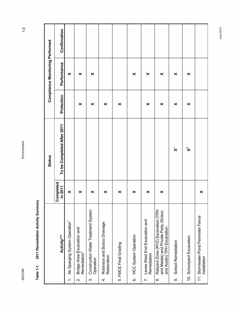
The remediation activities described in this As-Built Report were performed from January 1, 2011 through December 31, 2011. Table 1-1 summarizes the activities that were planned for 2011, as originally described in the 2010 Engineering Design Report (EDR; AECOM 2010a) and 2010 Compliance Monitoring Plan Update (CMP; AECOM 2010b). The table summarizes the status of each activity including: 1) work completed in 2011, and 2) work initiated in 2011 and scheduled to be completed after 2011. The table also summarizes the types of compliance monitoring that were completed for each activity, as well as other relevant construction activities that were not described in the 2010 EDR, but were completed during 2011 consistent with the CAP and Master EDR.
AE
CO
M
E
nviro
nmen
t
Ju
ne 2
012
1-2
Tabl
e 1-
1 20
11 R
emed
iatio
n Ac
tivity
Sum
mar
y
Act
ivity
***
Stat
us
Com
plia
nce
Mon
itorin
g Pe
rfor
med
Com
plet
ed
in 2
011
To
be
Com
plet
ed A
fter 2
011
Prot
ectio
n Pe
rfor
man
ce
Con
firm
atio
n
1.
Air S
parg
ing
Syst
em O
pera
tion1
X
X
2.
Brid
ge A
rea
Exca
vatio
n an
d R
emed
iatio
n2 X
X
X
3.
Con
stru
ctio
n W
ater
Tre
atm
ent S
yste
m
Ope
ratio
n X
X
X
4.
Rob
inso
n an
d Sc
isco
Dra
inag
e R
esto
ratio
n X
X
5. F
MC
E Fi
nal G
radi
ng
X
X
6.
HC
C S
yste
m O
pera
tion
X
X
7.
Leve
e W
est E
nd E
xcav
atio
n an
d R
emed
iatio
n X
X
X
8.
Rai
lyar
d Zo
ne (R
YZ) E
xcav
atio
n (T
PH
and
Met
als)
and
Priv
ate
Party
(Sci
sco
and
Aust
in) T
PH E
xcav
atio
n X
X
X
9.
Scho
ol R
emed
iatio
n
X3 X
X
10. S
choo
lyar
d Ex
cava
tion
X3
X X
11. S
torm
wat
er P
ond
Perim
eter
Fen
ce
Inst
alla
tion
X
AE
CO
M
E
nviro
nmen
t
Ju
ne 2
012
1-3
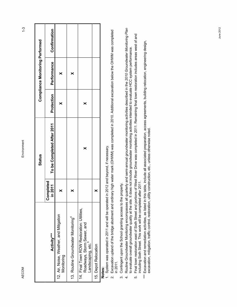
Act
ivity
***
Stat
us
Com
plia
nce
Mon
itorin
g Pe
rfor
med
Com
plet
ed
in 2
011
To
be
Com
plet
ed A
fter 2
011
Prot
ectio
n Pe
rfor
man
ce
Con
firm
atio
n 12
. Air,
Noi
se, W
eath
er, a
nd M
itiga
tion
Mon
itorin
g X
X
X
13. R
outin
e G
roun
dwat
er M
onito
ring4
X
X
14. F
inal
Tow
n R
OW
Res
tora
tion:
Util
ities
, R
oadw
ays,
Sto
rm S
ewer
, and
La
ndsc
apin
g, e
tc.5
X
X
15. D
epot
Rel
ocat
ion
X
Not
es:
1.
Syst
em w
as o
pera
ted
in 2
011
and
will
be o
pera
ted
in 2
012
and
beyo
nd, i
f nec
essa
ry.
2.
Exca
vatio
n up
land
of t
he b
ridge
abu
tmen
t and
ord
inar
y hi
gh w
ater
mar
k (O
HW
M) w
as c
ompl
eted
in 2
010.
Add
ition
al e
xcav
atio
n be
low
the
OH
WM
was
com
plet
ed
in 2
011.
3.
C
ontin
gent
upo
n th
e Sc
hool
gra
ntin
g ac
cess
to th
e pr
oper
ty.
4.
Rou
tine
Gro
undw
ater
Mon
itorin
g en
com
pass
es a
ll qu
arte
rly a
nd s
emi-a
nnua
l gro
undw
ater
mon
itorin
g ac
tiviti
es d
escr
ibed
in th
e 20
10 G
roun
dwat
er M
onito
ring
Plan
to
eva
luat
e ov
eral
l gro
undw
ater
qua
lity
at th
e si
te. I
t doe
s no
t inc
lude
gro
undw
ater
mon
itorin
g ac
tiviti
es in
tend
ed to
eva
luat
e H
CC
sys
tem
per
form
ance
. 5.
Fi
nal t
own
rest
orat
ion
east
of S
ixth
Stre
et a
nd p
ortio
ns o
f Wes
t Riv
er D
rive
was
com
plet
ed in
201
1. R
emai
ning
fina
l tow
n re
stor
atio
n in
clud
es a
reas
wes
t of a
nd
incl
udin
g Si
xth
Stre
et. T
his
wor
k w
ill be
com
plet
ed a
fter 2
011.
**
* Ex
cava
tion
and
rem
edia
tion
activ
ities
, as
liste
d in
this
tabl
e, in
clud
e al
l ass
ocia
ted
prep
arat
ion,
acc
ess
agre
emen
ts, b
uild
ing
relo
catio
n, e
ngin
eerin
g de
sign
, ex
cava
tion,
miti
gatio
n, tr
affic
con
trol,
rest
orat
ion,
util
ity c
onst
ruct
ion,
etc
., un
less
oth
erw
ise
note
d.
AECOM Environment
June 2012
1-4
1.1 Report Organization This As-Built report is organized into the following sections:
• Section 1.0 – Introduction
• Section 2.0 – Project Management and Organization. This section describes the roles and responsibilities of BNSF, AECOM, the general contractor and their consultants and subcontractors in the completion of the 2011 remediation activities.
• Section 3.0 – Permitting. This section describes the permitting activities that were conducted for the 2011 remediation.
• Section 4.0 – Site Preparation. This section describes the general site preparation activities that were completed prior to the start of construction.
• Section 5.0 – Construction Activities. This section describes the 2011 remediation construction activities, including: 1) activities described in the 2010 EDR, 2010 Construction Plans and Specifications (CPS; AECOM 2010c) and FMCE SDR that were completed in 2011; 2) additional activities that were completed, but not described in these documents; 3) related compliance monitoring activities.
• Section 6.0 – Work to be Completed After 2011. This section describes the remaining remediation activities described in the CPS that will begin or will be completed after 2011.
• Section 7.0 – Summary and Conclusions
• Section 8.0 – References
AECOM Environment
June 2012
2-1
2.0 Project Management and Organization
AECOM was retained by BNSF as the Engineer for the project. AECOM prepared the CPS, oversaw the remediation activities, and served as a liaison for BNSF with contractors, the Town of Skykomish (Town) and local stakeholders. Ecology provided regulatory oversight of the project. Brief descriptions of the roles of each contractor, subcontractor, consultant, and company in the 2011 remediation are provided below.
2.1 Primary General Contractor • Strider Construction Company (Strider) was responsible for implementation of the CPS,
execution of the project contract documents and requirements, and development and implementation of the 2011 Technical Execution Plan (TEP; Strider 2011). Strider provided a Construction Manager and Superintendent who were responsible for on-site management and coordination for the duration of the project. Strider generally performed excavation, backfilling and grading of remediation areas, loading of excavated materials for disposal, restoration, and infrastructure reconstruction.
2.1.1 Subcontractors to Strider • Clear Water Compliance Services, Inc. (CWCS) – Temporary construction water treatment
system (CWTS) installation and operation
• Economy Fencing – Stormwater Pond perimeter fence installation
• Fremont Analytical – Chemical analyses of discharge water from the temporary construction water treatment system
• GeoTest Services, Inc. – Soil compaction testing
• Inca Engineers (Inca) – Land surveying
• Lakeside Industries, Monroe Division – Street paving
• Marine Vacuum Service, Inc. (MARVAC) – Oil recovery
• McCandlish Electric, Inc. – HCC system maintenance and site-wide electrical work
• National Construction Rentals – Temporary site security fencing
• Nickel Bros. House Moving, Ltd. – Structure moving
• P&G – Depot Park, Bridge Area, Levee West End landscaping and irrigation installation
• S&S Concrete Construction Inc. – Concrete curb, gutter and sidewalk construction
2.2 Consultants and Contractors to AECOM • Cascade Drilling – Well modifications
• Frontier Communications (Frontier; formerly Verizon Communications) – Communications utilities design and construction
• Major Drilling – Well installation and decommissioning
• SWCA Consultants (SWCA; formerly Northwest Archeological Associates Inc. ) – Archeological Monitoring and Discovery Plan development and implementation
AECOM Environment
June 2012
2-2
• Puget Sound Energy (PSE) – Electrical utilities infrastructure design and construction
• True North Land Survey, Inc. – Piezometer and monitoring well surveying
2.3 Consultants to the Town • Gray and Osborne, Inc. (G&O) – Town sanitary sewer system design
• KPG – Review of Town right-of-way restoration plans
2.4 Consultants and Contractors to BNSF • AECOM – Engineer of Record; CPS development; remediation oversight; compliance
monitoring; and BNSF liaison with contractors, Town, and local stakeholders
• Farallon Consulting – Design Engineer for Skykomish School work.
• EnviroIssues – Public outreach
• TestAmerica – Chemical analysis of soil samples and National Pollutant Discharge Elimination System (NPDES) permit water samples
• Pace Analytical Services, Inc. (Pace) – Chemical analyses of routine groundwater monitoring samples
• Rabanco/Allied Waste – Impacted soil disposal facility
AECOM Environment
June 2012
3-1
3.0 Permitting
The following permits (issued by the listed agencies) were obtained by BNSF prior to the commencement of the 2011 remediation work:
• NPDES permit – Ecology
• Clearing and grading permit – Town
• Nationwide 38 permit – USACE (lead agency). This permit was required for Bridge Area and Levee West End excavation below the Ordinary High Water Mark (OHWM). It was applied for via the Joint Aquatic Resources Permit Application (JARPA), which was submitted to USACE, Ecology, Washington State Department of Natural Resources, U.S. Fish and Wildlife Service (USFWS) and WDFW
• Clean Water Act Section 404 Permits to Discharge Dredged or Fill Material (in-water excavation permit) – U.S. Army Corps of Engineers (USACE)
• Bridge permit – Washington State Department of Transportation (WSDOT). This permit was issued for construction activities around the bridge abutment, levee and bridge pier. Prior to the Bridge Area remediation, AECOM submitted a technical memorandum to WSDOT describing the proposed excavation and restoration of the Bridge Area, and a traffic control strategy. Impacts to bridge traffic, and mitigation methods were described in the permit.
Copies of all the above-listed permits are included in Appendix A.
3.1 NPDES Permit CWTS system discharges during the 2011 remediation were performed in accordance with the project NPDES permit (Permit No. WA-003212-3; Ecology 2011).
The NPDES permit was originally issued on May 4, 2006 and authorized discharge of excavation dewatering water and industrial stormwater resulting from levee remediation activities to Outfall 1. Four modifications to the NPDES permit have been authorized since the issuance of the permit.
• Modification 1 (issued August 15, 2006) increased the stringency of some of the permit conditions and set the criteria that allowed flexibility to BNSF in choosing between two approved chitosan products for water treatment.
• Modification 2 (issued June 30, 2008) authorized CWTS discharge at Outfall 2 (Sixth Street outfall), HCC system discharge at Outfall 3 (3rd Street outfall), and HCC system effluent injection to groundwater wells IW-1 and IW-2.
• Modification 3 (issued June 23, 2010) increased the allowable summer seasonal CWTS Outfall 2 discharge flow rate.
• Modification 4 (issued June 21, 2011) renewed the existing permit.
Per the NPDES permit requirements, BNSF prepared and implemented the updated 2011 Stormwater Pollution and Prevention Plan (SWPPP; AECOM 2011).
BNSF submitted monthly discharge monitoring reports to Ecology. CWTS operation is described in Section 4.0. HCC system operation, including railyard subsurface injection to support hydraulic containment at the east side of the HCC barrier wall and to flush free product toward the recovery wells between the central and west gates is described in Section 5.0.
AECOM Environment
June 2012
4-1
4.0 Site Preparation
4.1 Pre-Construction Meeting, Weekly Construction Meetings and Stakeholder Meetings
A pre-construction meeting was held in Skykomish on June 15, 2011. Meeting attendees included representatives of Strider, AECOM, and BNSF. The key items discussed in the meeting were:
• Roles and responsibilities
• Communication protocol
• Site health and safety
• Weekly construction meetings
• Project contacts
• Submittal procedure
• Anticipated construction schedule
Weekly on-site construction meetings were held to review construction activity status and to address any construction issues related to the CPS and the project contract. Meeting attendees included representatives of BNSF, AECOM, EnviroIssues, Strider, and select subcontractors. The meeting agenda generally included the following:
• Health and safety concerns
• Construction status
• Discussion of construction issues
• Review of three-week look ahead project schedule
• Submittal status and delivery schedule
• Review of contract modifications
• Project financial performance
• Public outreach concerns
Bi-weekly on-site stakeholder meetings and conference calls were also held during the construction season following the weekly construction meetings. The attendees included representatives of AECOM, Ecology, EnviroIssues, and the Town. At the stakeholder meetings, AECOM provided updates on the project schedule and planned construction activities, and responded to any Ecology and/or Town construction-related questions.
4.2 Monitoring Well Decommissioning, Installation and Modification 4.2.1 Decommissioning of Existing Monitoring Wells In support of 2011 construction, three monitoring wells located within the excavation area, MW-28, 5-W-20, and 5-W-42 were decommissioned by Major Drilling (a Washington State licensed well driller). The wells were decommissioned in accordance with WAC 173-160-381, using either chipping-in-place or over-drilling methods. It is planned that MW-28 will be replaced, but as wells 5-W-20 and 5-W-42 were right next to one another, only one replacement well is necessary. The anticipated
AECOM Environment
June 2012
4-2
replacement schedule is June or July of 2012. The monitoring well 1C-W-2 was damaged when the Town installed a sanitary sewer line. Since the well’s installation in 2001, no detected concentrations of standard NWTPH-Dx have been reported. This includes 13 rounds of groundwater sampling events. Based on the repeated non-detects and the placement of the end well, EW-2A, located approximately 450 feet east of Third Street along the Railroad Avenue corridor, it is not planned to reinstall 1C-W-2.This well is currently buried and AECOM is awaiting a variance from Ecology to work around the sewer line and perform final decommissioning.
Well locations are shown on Figure 2. Copies of the well decommissioning reports are included in Appendix B.
4.2.2 Installation of New Monitoring Well Monitoring well EW-2A was installed at the east of the HCC barrier wall in 2011 by Major Drilling. The well location is shown on Figure 2. A copy of the well installation report is included in Appendix B. Further detail of this activity is explained in Section 5.4.
4.2.3 Monitoring Well Modifications In addition to well decommissioning and installations, eleven active monitoring wells were modified. Each well riser was raised to match final restoration grades. Wells GW-1, GW-2, GW-3, and 1A-W-4 are located in roadways where permanent paving occurred. Wells EW-1, 2A-W-41, 2A-W-42, and GW-4 are located in landscaping areas south of Railroad Avenue. Wells 2A-W-40, 1B-W-23, and 1C-W-7 are located in sidewalks where permanent sidewalks were installed. At each well, the monument was chipped out and removed, an extension was added to the well casing, and a new monument installed and set to final grade. The wells were then re-surveyed. Cascade Drilling performed the modifications with AECOM oversight. The well locations are shown in Figure 2.
4.3 Temporary Facilities and Controls Strider and their subcontractors provided the following 2011 remediation temporary facilities and controls. The locations of these facilities, where appropriate, are shown on Figure 3.
4.3.1 Construction Trailers Strider provided jobsite trailers with electricity, HVAC, first aid kits, fire extinguishers, eyewash kits, printer, scanner, fax machines, and telephone lines with high-speed internet access. The trailers were used by Strider, AECOM, and McCandlish Electric as field offices. Strider also provided a number of portable restrooms for on-site personnel and visitors.
4.3.2 Soil Handling Facility (SHF) Prior to stockpiling impacted material in 2011, Strider repaired portions of the Soil Handling Facility (SHF) asphalt surface and high density polyethylene (HDPE) liner beneath the asphalt surface that were damaged during 2010 construction and the 2010-2011 winter off-season. In areas where the HDPE liner was damaged, a new piece of HDPE liner was installed directly over the damaged liner with at least 12 inches additional length in all directions. After the new liner was installed, a compacted asphalt layer was constructed on top of the repaired liner. All directions detailing the repair of the SHF are shown on Detail Number 3/C-102 on Drawing C-107 of the 2009 CPS and written in the 2009 specifications (Section 01500 – 1.12).
AECOM Environment
June 2012
4-3
4.3.3 Temporary Traffic Control
4.3.3.1 Railroad Crossing
The Fifth Street public crossing was used by Strider as the sole access to the SHF during construction. When necessary, a railroad flagger provided by BNSF was stationed at the Fifth Street public crossing to alert construction personnel of train traffic. BNSF railroad protocol required this railroad flagger whenever construction activities would encroach upon the railroad tracks with the potential of fouling the track. Construction activities would stop during train traffic, as directed by the BNSF flagger, and would then commence only when given permission to do so by the flagger.
4.3.3.2 Temporary Roads and Detours
Strider developed a temporary traffic control plan (TCP), as part of the 2011 TEP. The TCP described temporary road lane adjustments, detours, and road closures designed to maximize pedestrian and driver safety, while minimizing delays during construction.
Temporary detours were made during construction to accommodate different construction activities and were updated when field conditions changed or required modifications.
Temporary traffic signage was placed strategically to alert and warn drivers and pedestrians. Information concerning temporary roads, closures, and detours was communicated to the Town and Ecology through the bi-weekly stakeholder meetings prior to the closures and detours.
4.3.4 Temporary Erosion and Sediment Controls (TESCs) Silt fencing was installed in applicable areas at the excavation boundaries to control sediment and silt runoff. Sediment filter socks/inserts were installed in catch basins located in areas that were affected by the remediation activities. A certified TESC inspector from Strider inspected these measures in accordance with the SWPPP. Repair and replacement of these controls was made if it was determined that the control was not functioning as planned as determined by the TESC inspection. The TESC inspection reports are included in Appendix C.
4.3.5 Biological Opinion Compliance and Turbidity Monitoring and Mitigation Planning
The 2011 remediation activities were completed in accordance with the special conditions described in the Biological Opinions (BO) prepared by the National Marine Fisheries Services (NMFS; Reference #: 2010/ 01872, October 7, 2010), and the U.S. Fish and Wildlife Service (USFWS; Reference #:13410-2010-F-0362, March 15, 2011) as part of the Nationwide 38 permit. These conditions included project timing and scope, fish exclusion measures, and water quality monitoring and reporting. Turbidity monitoring and mitigation was completed by AECOM and Strider in accordance with the Turbidity Monitoring and Mitigation Plan (TMMP). The TMMP incorporated information described in the 2010 CMP and the Nationwide 38 permit requirements. The TMMP was included in Section F of the TEP, which was submitted to Ecology for review and comment prior to construction. Biological Opinion compliance is described in Section 5.12. TMMP implementation is described in Section 5.13.
4.3.6 Construction Water Treatment System (CWTS) Facility The CWTS was installed by CWCS on the railyard west of the SHF prior to the commencement of construction activities. The approximate location of the CWTS is shown on Figure 3. The CWTS was operated from June 27, 2011 to September 22, 2011. The CWTS treated water removed from the active excavation areas and stormwater runoff collected within the SHF. The CWTS was operated
AECOM Environment
June 2012
4-4
and maintained in accordance with the Operations and Maintenance Manual for Water Treatment System (AECOM 2010d) and monitored in accordance with the NPDES permit requirements.
A total of 783,150 gallons of water was treated and discharged from the CWTS between June 30, 2011 and September 21, 2011. NPDES permit-required CWTS monitoring was performed by CWCS and NPDES samples were analyzed by Fremont Analytical in Seattle, Washington. CWCS prepared weekly water treatment system operations reports, which are included in Appendix D. Data from these reports were included in the BNSF monthly discharge monitoring reports (DMRs) which were submitted to Ecology. All CWTS discharges in the 2011 remediation were in compliance with the NPDES permit requirements.
The CWCS began the CWTS demobilization on September 23, 2011. A temporary storage system consisting of three 20,000-gallon Baker tanks was used to handle SHF runoff during and after the CWTS demobilization. MARVAC assembled the Baker tanks on the RYZ service road and Strider reassembled the SHF sump pump to transfer impacted water into the tanks. MARVAC pumped out the tanks on an as-needed basis and disposed of the impacted water off-site at its licensed wastewater treatment facility. A total of 290,800 gallons of water/oil mix was pumped and removed by MARVAC from the tanks and disposed of off-site.
4.3.7 Clearing and Grubbing A designated clean overburden storage area was prepared in 2008 by clearing, grubbing, and rough-grading a section of the railyard as shown on Figure 3. In 2011, all clean overburden from the Levee West End, Bridge Area and Schoolyard were temporarily stored in this designated area. Additionally, all foliage, trees, shrubs, and organic debris removed from these areas were stockpiled in the clean overburden storage area for eventual chipping and onsite or offsite recycling/reuse.
4.4 Surveying True North conducted an initial land survey of the site in November 2007. The 2007 survey covered most of the remediation areas planned for 2008 and beyond. Additional surveying data was appended to the initial survey during the 2011 period, as requested by AECOM. The survey control points established by True North were used by Strider’s surveyor, Inca, for locating the construction areas and site features. Strider utilized the survey-grade global positioning system (known as a Total Station) to locate site features in the field.
Further surveying will be performed, as needed, when the school remediation and final restoration is completed west of Sixth Street.
4.5 Structure Relocation 4.5.1 Pre-Move Inspection The only building that was moved and placed at its permanent location during the 2011 construction activities was the Depot. Nickel Brothers completed a pre-move inspection to evaluate the rigging that was kept under the structure since its initial move during the 2008 construction season. As required in the CPS, Strider performed a pre-move video survey in 2008 to document the pre-existing interior and exterior conditions of the building.
4.5.2 Depot Relocation The Depot was moved by Nickel Brothers on November 4, 2011 from its temporary location on East Railroad Avenue to its permanent location on the railyard west of the SHF. The structure relocation
AECOM Environment
June 2012
4-5
work was completed in accordance with the requirements described in the Master EDR, TEP, and CPS. See Section 5.5.3 for further details. The design and construction of the new foundation for the Depot was not part of the 2011 scope of work. Per agreement with BNSF, the Town of Skykomish will construct a foundation for the Depot; consequently no building permits were sought by BNSF or obtained through the Town.
4.6 Archeological Monitoring Archaeological monitoring was conducted during the remediation work at the Levee West End and Schoolyard in accordance with the Archaeological Resources Monitoring and Discovery Plan (ARMDP; NWAA 2010). Archaeological monitoring was performed prior to any excavation activities. Monitoring results will be provided in a forthcoming SWCA report, which is scheduled to be finalized in mid-2012. Artifacts recovered from private properties will be returned to their respective property owners. Artifacts recovered from BNSF and public properties (e.g. Town right-of-way [ROW]) will be curated at the Burke Museum or Town of Skykomish Historical Society.
AECOM Environment
June 2012
5-1
5.0 Construction Activities
The 2011 remediation scope of work included the following activities described in the 2010 EDR and/or CPS:
1. Operation of HCC treatment systems installed in 2008/2009 and ancillary activities such as maintenance and routine sampling
2. Levee West End remediation
3. Partial Schoolyard remediation
4. Bridge Area remediation
5. RYZ remediation
6. Final infrastructure restoration at the following areas:
− Levee West End and West River Drive
− East side of Sixth street
− All of Railroad Avenue from the east side of Sixth Street to the extents of 2008 remediation construction.
− Fifth Street south of the bridge to the railroad crossing
− All of East River Drive
− All of Fourth Street
− South end of Third Street adjacent to the Verizon building.
Final infrastructure restoration included landscaping of public and private properties, utilities installation (electrical power, telecommunications, street lights, stormwater sewers, and portable water), construction of concrete sidewalks, curbs & gutters, and final asphalt paving.
BNSF conducted performance, protection, and mitigation monitoring to confirm that human health and the environment were adequately protected during construction. This section describes each of these activities in detail. Each remediation area (i.e. Levee West End, Bridge Area, RYZ, etc.) is described separately. Monitoring activities are described by area, where appropriate, and separately where they are not area-specific.
BNSF submitted weekly progress reports to Ecology as required by the CD. AECOM documented activities in daily construction reports, which are included in Appendix E. Photographs showing the construction activities are included in Appendix F and are identified by the following construction phases:
• Phase 1 – Levee West End remediation
• Phase 2 – West End of Schoolyard excavation
• Phase 3 – Bridge Area remediation
• Phase 4 – RYZ TPH excavation
• Phase 5 – RYZ metals excavations
AECOM Environment
June 2012
5-2
The following subsections describe the 2011 construction activities summarized above.
5.1 Soil Sample Overview The 2011 soil sampling included: 1) soil sampling to characterize overburden in areas not sampled in previous construction seasons; 2) below vertical delineation limit (VDL) sampling to support excavation; and 3) excavation performance sampling to determine whether the remediation level (RL) and/or cleanup level (CUL) had been achieved.
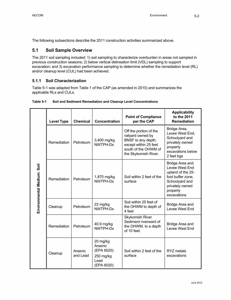
5.1.1 Soil Characterization Table 5-1 was adapted from Table 1 of the CAP (as amended in 2010) and summarizes the applicable RLs and CULs.
Table 5-1 Soil and Sediment Remediation and Cleanup Level Concentrations
Envi
ronm
enta
l Med
ium
: Soi
l
Level Type Chemical Concentration Point of Compliance
per the CAP
Applicability to the 2011
Remediation
Remediation Petroleum 3,400 mg/kg NWTPH-Dx
Off the portion of the railyard owned by BNSF to any depth, except within 25 feet south of the OHWM of the Skykomish River.
Bridge Area, Levee West End, Schoolyard and privately owned property excavations below 2 feet bgs
Remediation Petroleum 1,870 mg/kg NWTPH-Dx
Soil within 2 feet of the surface
Bridge Area and Levee West End upland of the 25-foot buffer zone, Schoolyard and privately owned property excavations
Cleanup Petroleum 22 mg/kg NWTPH-Dx
Soil within 25 feet of the OHWM to depth of 4 feet
Bridge Area and Levee West End
Remediation Petroleum 40.9 mg/kg NWTPH-Dx
Skykomish River Sediment riverward of the OHWM, to a depth of 10 feet.
Bridge Area and Levee West End
Cleanup Arsenic and Lead
20 mg/kg Arsenic (EPA 6020) 250 mg/kg Lead (EPA 6020)
Soil within 2 feet of the surface
RYZ metals excavations
AECOM Environment
June 2012
5-3
5.2 Excavation Overview Excavations were completed in several phases to facilitate soil handling, temporary storage, soil load-out and Nationwide 38 permit conditions. Excavation performance sampling and backfilling was typically completed for each phase before proceeding to the next phase.
The excavations were performed in the following sequence:
• Phase 1: Levee West End
• Phase 2: West end of schoolyard
• Phase 3: Bridge Area, including in-water excavation and cofferdam construction.
• Phase 4: RYZ TPH excavations
• Phase 5: RYZ metals excavations
5.2.1 Backfill Materials Backfill materials used in the excavation areas were specified in the CPS. The contractor submitted the testing results for each borrow source material for review and approval prior to importing the materials to the site to demonstrate that the proposed material met the project specifications. The contractor submittals and AECOM responses to these submittals are included in Appendix G.
5.3 Remediation Areas 5.3.1 Levee West End The Levee West End remediation is described in the 2010 CPS. The excavation extents (both planned and actual) of the Levee West End remediation are shown on Figure 4. All excavation was completed upland of the buffer zone boundary.
5.3.1.1 Overburden Pre-Characterization
The Levee West End excavation and pre-characterization of overburden was conducted in accordance with the procedures described in the 2010 Sampling and Analysis Plan (SAP)which is 2010 CMP Appendix D. The clean overburden soil was removed from within the excavation area, transported to and temporarily stockpiled in the designated clean soil storage area and later reused on-site where possible. The impacted overburden soil was excavated and transported to the SHF for off-site disposal. A sampling grid plan shown in Figure 4 was developed for the excavation and pre-characterization of overburden. Analytical results are summarized in Table 5-2.
5.3.1.2 Below VDL Excavation
After the overburden was removed and temporarily stockpiled in the designated storage area, the impacted soils below the VDL within the excavation area were excavated and transported to the SHF for off-site disposal. Performance sampling was completed as described in the SAP using the sampling grid shown in Figure 4. Analytical results are summarized in Table 5-3.
5.3.1.3 Petroleum Hydrocarbon-Impacted Soil Excavation beyond Planned Excavation Limits
Two additional excavations were conducted beyond the planned Levee West End excavation limits at grid cells B1 and B2 to remove impacted soils.
Grid Cell B1
AECOM Environment
June 2012
5-4
Only a small part of grid cell B1 upland of the buffer zone boundary was excavated. Performance sampling (sample EXV11-WL-B1-WW) results indicated that grid cell B1 west wall NWTPH-Dx concentrations exceeded the 3,400 mg/kg RL. Additional soil was removed from the B1 west excavation sidewall. This excavation increased the sidewall slope, but did not expand the excavation footprint or encroach on the adjacent private property. Performance sampling (sample EXV11-WL-B1-WW’) confirmed that the NWTPH-Dx concentration at the expanded excavation sidewall was below the RL.
Grid Cell B2
Performance sampling (sample EXV11-WL-B2-NW) results indicated that grid cell B2 north wall NWTPH-Dx concentrations exceeded the 3,400 mg/kg RL. The excavation was extended north to near the buffer zone boundary. Additional soil was removed from the B2 north excavation sidewall without expanding the excavation into the buffer zone. Performance sampling (sample EXV11-WL-B2-NW’), completed several feet south of the buffer zone, confirmed that the NWTPH-Dx concentrations fell below the RL.
5.3.1.4 Grid Cells Not Sampled
Grid Cell E3
Overburden sampling, as well as sidewall and bottom performance sampling were not completed for grid cell E3. As shown on Figure 4, this cell is located at the Levee West End excavation south boundary. This cell was not excavated because a guy wire from a nearby telephone/power pole was embedded into the ground within the grid cell. With consultation from PSE, it was determined that excavating grid cell E3 would de-stabilize the pole and compromise active overhead wires being held by that pole. Sidewall samples from adjacent grid cells, such as EXV11-WL-E4-WW (a sample into the east sidewall of cell E3) and EXV11-WL-D3-SW (a sample into the north sidewall of cell E3), determined that grid cell E3 did not contain NWTPH-Dx concentrations above the 3,400 mg/kg RL. Both sidewall samples were non-detect for NWTPH-Dx (<27 mg/kg diesel and <54 mg/kg oil for EXV11-WL-D3-SW and <32 mg/kg diesel and <64 mg/kg oil for EXV11-WL-E4-WW).
Grid Cell C1
This cell was effectively combined with cell B1. The B1 sidewall sampling results are therefore representative of soil quality in C1.
Grid Cells B6 and C6
These cells consisted entirely of clean backfill that was placed during the 2006-2007 levee remediation, and were therefore not sampled.
Grid Cells F5, F6, F7, and F8
Only partial side-slope excavations were completed in these cells. The side-slopes extended into cells E5, E6, E7, and E8. Sidewall samples were collected from these E-row cells.
5.3.1.5 Archaeological Monitoring, Protection and Documentation
Archaeological monitoring, protection, and documentation were performed in this excavation area in accordance with the ARMDP. Findings in this area will be included in the SWCA report.
AECOM Environment
June 2012
5-5
5.3.1.6 Backfilling and Grading
The Levee West End excavation was backfilled to the final grade in accordance with the CPS and private property access agreements. Representative project photos for the Levee West End excavation are in Appendix F under Phase 1 (Levee West End).
5.3.2 Schoolyard The Schoolyard is described in the 2010 CPS. The excavation extents (both planned and actual) of the Schoolyard remediation are shown on Figure 4. Excavation was completed in Schoolyard grid cells in columns 7 and 8 only. The remainder of the planned Schoolyard excavation area could not be completed in 2011 because access could not be obtained. In order to adequately excavate the planned area, a large wood fence located along the eastern boundary of the Schoolyard was dismantled and removed. This fence was re-constructed using new materials after the excavation was complete.
5.3.2.1 Overburden Pre-Characterization
The Schoolyard overburden pre-characterization and below VDL excavation were performed in accordance with the procedures described in the SAP. The sampling grid shown in Figure 4 was developed for the overburden pre-characterization and below VDL excavation. Analytical results are summarized in Table 5-2.
5.3.2.2 Below VDL Excavation
After the overburden was removed and temporarily stockpiled in the designated area, the impacted soils below the VDL within the excavation area were excavated and transported to the SHF for off-site disposal. Performance sampling was completed as described in the SAP using the sampling grid. Analytical results are summarized in Table 5-3.
5.3.2.3 Petroleum Hydrocarbon-Impacted Soil Excavation beyond the Planned Excavation Limits
Performance sampling (samples EXV11-WL-D8-EW and EXV11-WL-E8-EW) results indicated that grid cell D8 and E8 east wall NWTPH-Dx concentrations exceeded the 3,400 mg/kg RL. Additional excavation could not be completed due to the lack of an access agreement. The excavation sidewall was lined with a plastic liner before the excavation was backfilled.
5.3.2.4 Grid Cells Not Sampled
Grid Cell C7
These cells consisted entirely of clean backfill that was placed during the 2006-2007 levee remediation, and was therefore not sampled.
Grid Cells C9, D9, E9, and F9
These cells will be sampled after they are excavated in entirety.
5.3.2.5 Archaeological Monitoring, Protection and Documentation
Archaeological monitoring, protection, and documentation were performed in this excavation area in accordance with the ARMDP. The findings will be described in the SWCA report.
AECOM Environment
June 2012
5-6
5.3.2.6 Backfilling and Grading
The Schoolyard excavation was backfilled to the final grade in accordance with the CPS.
Representative project photos for the west Schoolyard excavation are in Appendix F under Phase 2 (Schoolyard).
5.3.3 Bridge Area The Bridge Area included the buffer zone (within 25 feet of the OHWM) and in-water (below the OHWM) excavation areas in the vicinity of the bridge pier and abutment by the Skykomish River.
The excavation limits (both planned and actual) are shown in Figure 5.
The following activities were performed in accordance with the TEP and Nationwide 38 permit prior to in-water excavation:
• Replacement of petroleum-based hydraulic fluids with non-petroleum hydraulic fluids for in-river construction equipment
• Installation of a triple redundant emergency oil recovery system to mitigate any accidental oil releases. The first level was a collection point approximately 160 feet downstream of the cofferdams and consisted of containment booms that were placed to channel, capture and recover any floating oil and prevent it from moving farther downstream. The second level was another deployment of containment booms located approximately 600 feet downstream of the cofferdams and organized in the same manner as the level one system. The third level was a collection point of containment booms located approximately one-half mile downstream of the cofferdams. This third and final level of containment booms were not deployed, but were on-standby at the riverbank. In the event of a major oil release these booms would be deployed with a boat that was stationed on-site.
• Completion of a drill to verify the efficacy of the recovery system.
• Installation of a current deflection structure (rock barb). This feature was placed in the Skykomish River to divert river current and energy away from the work area. The structure consisted of large boulders placed upstream of the work area and angled in such a way so as to create a static or minimal flow condition in the excavation area. This feature aided construction of the cofferdams and minimized turbidity during construction.
• Construction of inner and outer cofferdams. The locations and orientations of the cofferdams are depicted in Figure 5. Each cofferdam was constructed of three vertical layers of Flexible Intermediate Bulk Containers (FIBC) bags filled with aggregates specified to match pre-existing river gravels as close as possible. The bottom layer held three rows of FIBC bags, the middle layer contained two rows of FIBC bags, and the top layer held one row of FIBC bags. After the bags were placed, a layer of plastic was placed over the cofferdams to prevent water from running between the sacks and act as a current inhibitor. Finally, a turbidity curtain and oil boom was placed in-between the two cofferdams to act as an additional safeguard to mitigate potential oil and turbidity releases.
• Mitigation activities required by the BOs, and as described in Section 5.12.
Representative project photos for the in-river work are in Appendix F under Phase 3 (Bridge Area).
AECOM Environment
June 2012
5-7
Overburden sampling in Bridge Area upland and buffer zone excavation areas was completed during the 2010 construction season; therefore, no overburden sampling was performed in 2011. The sampling results are described in the 2010 Remediation As-Built Completion Report (AECOM 2011).
5.3.3.1 Below VDL Excavation
Below VDL excavation performance sampling was completed using the grid shown in Figure 5 and as described in the SAP. Analytical results are summarized in Table 5-3.
5.3.3.2 Additional Excavation beyond the Planned Limits
Grid cells S10 and V11 are located, in part, in the buffer zone. Performance sampling (samples EXV11-Bridge-S10-B and EXV13-Bridge-V13-EW) results indicated that S10 bottom and V13 sidewall NWTPH-Dx concentrations were above the 22 mg/kg CUL. The excavations were extended accordingly. Performance sampling (samples EXV11-Bridge-S10-B’ and EXV11-Bridge-V13-EW’) confirmed that the NWTPH-Dx concentrations at the expanded excavation bottoms and sidewall, as appropriate, were below the 22 mg/kg CUL.
Grid cell V11 is located in the waterward of the OHWM. Performance sampling (sample EXV11-Bridge-V11-B) results indicated that V11 bottom NWTPH-Dx concentrations were above the 40.9 mg/kg RL. Additional sediment was removed from the excavation bottom. Performance sampling (sample EXV11-Bridge- V11-B’) confirmed that the NWTPH-Dx concentrations at the expanded excavation bottoms and sidewall, as appropriate, were below the 40.9 mg/kg RL.
5.3.3.3 Grid Cells Not Sampled
Grid Cells R9, R10, R11, S11, S12, S13, S14, T13, T14, U14, and V14
These cells consisted entirely of clean backfill that was placed during the 2010 bridge area excavation, and were therefore not sampled.
Grid Cells T8, U8, and V8
Only partial side-slope excavations were completed in these cells. The side-slopes extended into cells T9, U9, and V9. Samples were collected from these column 9 cells.
5.3.3.4 Archaeological Monitoring, Protection and Documentation
Archeological monitoring was not required for this excavation area.
5.3.3.5 Backfilling and Grading
The Bridge Area excavation was backfilled to the final grade in accordance with the CPS.
Representative project photos for the Bridge Area and in-water backfilling and grading are in Appendix F under Phase 3 (Bridge Area).
5.3.4 Railyard Zone Excavation The RYZ remediation consisted of excavating three metals-impacted areas (designated M1 , M2 and M3 on Figures 6 through 8) to a depth of 2 feet below ground surface (bgs), and three TPH-impacted soil areas (designated T1, T2 and T3 on Figures 6 through 8). The RYZ metals-impacted areas were located in: 1) the gravel parking area by the construction trailers (M1); 2) an area stretching from the gravel parking area eastward through the SHF, south of the train-tracks (M2); and 3) in two areas in-between the train-tracks along haul roads (M3).
AECOM Environment
June 2012
5-8
The RYZ TPH-impacted excavation areas included: 1) an opportunistic dig area (T1); 2) the free product area located at the east end of the RYZ (T2); and 3) the free product area located at the RYZ-FMCE boundary along the “truck haul” route (T3). The excavation limits (both planned and actual) for all RYZ excavations and the associated sampling gridlines are shown in Figures 6 through 8.
The SHF was reconfigured in order to excavate some of the impacted soils. The perimeter ecology blocks were moved to a new perimeter and the SHF sump pump was moved to a new location. The reconfigured SHF is depicted in Figure 3.
5.3.4.1 Metals Excavation Performance Monitoring
Metals excavation performance sampling was completed using the sampling grid shown in Figures 6 through 8, and as described in the SAP. Where necessary, grid cells were over-excavated to remove additional soil with lead and/or arsenic concentrations exceeding CULs where no obstructions were present (e.g., railroad tracks, buildings). Over-excavation was not completed in areas where obstructions occurred and advancement became impossible. Excavated areas were backfilled to final grade. Analytical results are summarized in Table 5-4.
Representative project photos for the RYZ metals excavation are in Appendix F under Phase 5 (RYZ Metals).
5.3.4.2 Metals Grids Not Excavated and/or Sampled
The excavated RYZ metals-impacted soil was stockpiled in the area of grid cells G31, G32, H31, H32, and I31 (M1 area) during the 2011 construction. The soil stockpile currently remains on site and is covered with polyethylene sheeting. The grid cells underneath the stockpile were not excavated in 2011, but are anticipated to be excavated during the summer of 2012, after the soil stockpile has been removed from the area.
The BNSF operations trailer is located in grid cells F8, F9 and F10, as shown in Figure 6. These cells have not been excavated in 2011, but are anticipated to be excavated during the summer of 2012, after the trailer has been removed from the area.
5.3.4.3 TPH Excavation Performance Monitoring
Opportunistic Dig (T1)
The CD and CAP require an “opportunistic dig” that would remove a minimum of 7,500 cubic yards of TPH-impacted soil from the RYZ. Approximately 1,840 cubic yards of this opportunistic dig soil was excavated in 2007 and 2008 as documented in the 2008 Skykomish Remediation – As-Built Completion Report (AECOM 2009). An additional 6,245 cubic yards of opportunistic TPH-impacted soil was removed from the RYZ in 2011 as described in Figure 10. The total quantity removed is 585 cubic yards more than the 7,500 cubic yards required by the CD and CAP. Since this was a bulk soil removal based on cubic yards removed and not an RL, no soil samples were collected. Excavation limits were instead determined based on visual impacts, property boundaries, physical structures, and train tracks. The opportunistic dig excavation and its associated contour lines are shown in Figures 6 and 7.
Free Product Areas (T2)
In addition to the opportunistic dig, an additional 1,100 cubic yards of LNAPL-impacted soil was scheduled to be excavated from an area in the eastern portion of the SHF. This excavation was a bulk soil removal where the boundaries were based on cubic yards removed and not laboratory analyses. Therefore, no soil samples were collected. This was a scheduled excavation and was not part of the
AECOM Environment
June 2012
5-9
opportunistic dig. In total, 1,635 cubic yards of soil was excavated; this is 535 cubic yards more than planned. The excavation and its associated contour lines are shown in Figure 7.
Representative project photos for the RYZ TPH excavations are in Appendix F under Phase 4 (RYZ TPH).
5.3.4.4 Archaeological Monitoring, Protection and Documentation
Archeological monitoring was not required in this excavation area.
5.3.4.5 Backfilling and Grading
BNSF property excavation within the RYZ was backfilled in accordance with the CPS.
5.3.5 Austin, Robinson and Scisco Properties
5.3.5.1 Free Product Removal (T3)
As described in the 2010 Skykomish Remediation As-Built Completion Report Section 5.2.5.2, the free product area located at the RYZ-FMCE boundary was excavated during the 2010 construction season. In 2011, additional excavation was performed to remove the remaining TPH-impacted soil in this area. The 2011 excavation was completed on parts of the Austin and Scisco properties located within the RYZ and FMCE, as shown on Figures 6 and 7.
Performance sampling (samples EXV11-RYZE-J16-B’, EXV11-RYZE-J16-WW’, EXV11-RYZE-J16-SW’, EXV11-RYZE-J17-B’, EXV11-RYZE-J17-SW’, EXV11-RYZE-J18-B’, EXV11-RYZE-J18-EW and EXV11-RYZE-J18-SW’) confirmed that the NWTPH-Dx concentrations at the excavation bottoms and sidewalls were all below the 3,400 mg/kg RL. Analytical results are summarized in Table 5-3.
After the performance sampling, the excavation on the Austin and Scisco properties was backfilled in accordance with the CPS and all access agreement requirements.
5.3.5.2 Scisco and Robinson Properties Drainage Restoration
During the winter of 2010-2011, the owners of Scisco and Robinson properties reported water ponding in their backyards. Upon inspection by AECOM and Strider, it was determined that the ponding occurred in the portions of the properties that were not part of the 2010 FMCE remediation area.
To enhance surface drainage, the FMCE backfill on the Scisco property was reshaped on May 27, 2011 by pulling back the backfill towards the west to widen the drainage path, and the grate of Catch Basin #7 (CB #7) was adjusted and lowered by approximately 2 inches (storm pipe invert elevations remain the same).
An active drainage system was constructed to enhance stormwater drainage on the Robinson property. Three yard drains were installed in the southwest corner of the parcel and the drains were piped to CB #7. A swale was constructed near the north property line to promote active surface drainage to CB #7 on December 2, 2011. Hydroseeding was reapplied to the Austin property on November 29, 2011 to complete the final grading restoration work activities.
Representative project photos for the Scisco and Austin TPH excavation and the Scisco, Robinson and Austin drainage modifications are in Appendix F under Robinson Drainage Revision and Phase 4 (RYZ TPH).
AECOM Environment
June 2012
5-10
5.3.5.3 Archaeological Monitoring, Protection and Documentation
Archeological monitoring was not required in this excavation area.
5.4 HCC Operation The HCC system construction was largely completed in 2008 and is described in the 2008 Skykomish Remediation – As-Built Completion Report (AECOM 2009). End well EW-1, four gate wells (GW-1 through GW-4), two recovery wells (RW-7 and RW-8), and related appurtenances were installed and the system went on line in 2009.The east end of the HCC barrier wall was extended in 2010. In order to properly evaluate groundwater conditions around the east end extension, an end well EW-2A was installed by Major Drilling east of the HCC barrier wall on May 26, 2011. The well location is shown on Figure 2. A copy of the well log is included in Appendix B. The HCC system operated from January 1 to December 31, 2011, as described in the Draft 2011 Annual Hydraulic Control and Containment System Operations Report (AECOM 2012a).
5.5 Air Sparging System Operation The air sparging system has been in operation since 2009 and operated from January 1 to December 31, 2011, as described in the Draft 2011 Annual Air Sparging System Report (AECOM 2012b).
5.6 Site Restoration 5.6.1 General Site Restoration Site restoration was completed in accordance with the CPS, the WSDOT Bridge permit and the Nationwide 38 permit. All private properties that were impacted in the 2011 remediation area were fully restored and returned to the property owners in accordance with the access agreement conditions. Within the Town ROW property, public utilities (i.e., potable water, electrical, telecommunications, storm and sanitary sewer) were fully restored as described in section 5.0. All general site restoration activities are depicted in the as-built drawings included in Appendix H. The scope of the 2011 site restoration included the following:
• Backfilling and grading of the excavated areas
• Constructing part of a stormwater sewer system
• Installing water main components
• Constructing new septic holding tanks and related appurtenances for the Sky River Inn properties
• Moving the Depot to its new location in the RYZ
• Restoring Depot Park and Railroad Avenue ROW landscaping
• Restoring electrical and telecommunications utilities services
• Paving roads east of Sixth Street with full curb, gutter, and sidewalks as described in Section 5.0
Representative project photos for final town restoration are in Appendix F under Site Surface Restoration, Site Utility Restoration, and Depot Park.
AECOM Environment
June 2012
5-11
5.6.2 Underground Utilities As there were no buildings moving back to the Sky River Inn properties, the utilities restoration for the Sky River Inn property essentially involved converting the pre-existing above-ground overhead electrical power and phone lines to underground utilities on East River Drive. The underground utilities restoration involved construction of the joint utility trench (JUT) in the public ROW, installation of conduit from the JUT to the graded and restored property as required in the access agreement. Inspections were performed and approved by the Washington Department of Labor and Industries. Water and Town sewer were installed per CPS and access agreement requirements. Frontier Communications installed conduit from the JUT to the property boundary and restored the telecommunications connection to pre-existing conditions as required in the access agreement.
5.6.3 Depot Relocation The Depot was the only building moved during the 2011 construction season. Since the Town of Skykomish will construct the foundation of the Depot, no building permits were sought by BNSF or obtained through the Town.
5.6.4 Stormwater Pond Perimeter Fence Installation BNSF constructed a 4-foot high chain-link fence around the perimeter of the FMCE stormwater pond, which was constructed in 2010. The proposed fence specifications and location (revised CPS drawings C-269 ALT and C-304) were submitted to and approved by the Town prior to construction. No-trespassing warning signs were installed at several locations on the fence. Representative project photos for the stormwater pond fence construction are in Appendix F under Stormwater Pond Fence.
5.7 Laboratory Analysis, Reporting and Data Validation Overburden pre-characterization samples, the NWTPH-Dx excavation performance samples and metals excavation performance samples were analyzed by the TestAmerica laboratory in Tacoma, Washington. Preliminary (unvalidated) laboratory reports were posted on the virtual project manager (VPM) website within 24 hours of receipt. The VPM website is a comprehensive web portal where all pertinent data are placed for Ecology review.
Excavation backfilling was completed based, in part, on unvalidated data. After backfilling was complete, AECOM reviewed all preliminary data to ensure that the QA/QC criteria established in the 2010 SAP were satisfied, and completed a Level III data evaluation of all preliminary laboratory results using standard EPA-approved procedures. Copies of the data validation reports are included in Appendix I. The laboratory reports for the overburden and performance samples are included in Appendix J.
5.8 Overburden and Impacted Materials Stockpiling The soils that were temporarily stockpiled on-site during the construction season included the pre-characterized clean overburden and the excavated TPH and metals impacted soils. The pre-characterized clean overburden was stockpiled in the designated “clean stockpile area” adjacent to the HCC remediation building; the TPH and metals impacted soils were stockpiled in the SHF.
5.8.1 Clean Overburden Material Stockpile As described in sections 5.1 and 5.3, some of the overburden in the remediation areas was pre-characterized prior to the excavation of impacted materials. The clean overburden was hauled to the clean stockpile area in off-road trucks. The trucks were decontaminated at the on-site decontamination area prior to hauling any clean material. As part of the site SWPPP, silt fence was
AECOM Environment
June 2012
5-12
installed around the stockpile area and weekly TESC inspections were conducted to ensure the stockpiled material was fully contained within the designated area. Clean overburden was re-used as backfill material only in publically-owned areas upland of the buffer zone. Clean overburden was not used for backfill in the schoolyard or private properties
5.8.2 Impacted Material Stockpile All the following impacted soils excavated during the 2011 construction season were transported to the SHF using off-road dump trucks and temporarily stockpiled in the SHF in anticipation of off-site disposal.
• Overburden with NWTPH-Dx concentrations at or above 1,870 mg/kg, and/or the overburden containing visible staining, burn-zone material or other debris unsuitable as backfill
• Upland soils from the Levee West End and Bridge Area excavated below the VDL
• Soil and sediment excavated from the in-river and buffer zones
• TPH-impacted and shallow metals-impacted soils excavated from the RYZ.
• TPH-impacted soils excavated from the School property and private properties.
At the end of the 2011 construction season after termination of off-site disposal rail transportation, two separate soil stockpiles remained on site in the SHF area (i.e., TPH-impacted soil stockpile and metals-impacted soil stockpile). These stockpiles will be disposed of in future arrangements. Both stockpiles have been covered with polyethylene sheeting and held down by sand bags since December 1, 2011. The approximate locations of the stockpiles are shown on Figures 3 (TPH) and 9 (metals). The TPH-impacted soil stockpile is located within the boundaries of the SHF, while the metals-impacted soil stockpile is located immediately east of the SHF. Note that the metals-impacted soil has been stockpiled directly on top of the remaining planned metals-impacted zone. The underlying metals-impacted soil is expected to be excavated during the off-site disposal of the stockpile.
Representative project photos for the soil stockpiles are in Appendix F under SHF Photos.
5.9 Stockpiled Impacted Soils Handling and Disposal The impacted soils in the SHF were loaded directly onto railcars and transported off-site to the Rabanco subtitle D waste disposal facility in Roosevelt, Washington. When the stockpiled soils contained free liquid water in excess of that allowed for railcars, the soils were gravity drained to facilitate drying. In the event that the soils could not be drained in a timely manner, the contractor installed liners in the railcars prior to loading the soils. Any water drained from the stockpile was collected and pumped to the on-site CWTS for treatment.
The impacted soils were loaded onto the railcars using a front end loader with an on-board scale. Prior to use at the site, the on-board scale was calibrated with an Ecology block whose weight was determined by a certified scale in Gold Bar, Washington. The scale provided soil load-out weight and assisted Strider in meeting weight limitations of the railcars. Railcar loading activities were typically performed two days per week. An average of 2,271 tons per week of impacted soils was transported offsite to the Rabanco disposal facility over the 2011 construction period. The total quantity of impacted soil removed from the site for the 2011 construction season was 43,144 tons. This quantity does not reflect the remaining stockpiled soils to be removed.
AECOM Environment
June 2012
5-13
Due to the lack of available railcars, inclement weather and subsequent extension of the construction schedule beyond the anticipated construction season, hauling of impacted material using railcars was suspended on November 27, 2011. As of December 31, 2011, approximately 2,000 tons of TPH-impacted soil and 3,000 tons of metals-impacted soil currently remain on-site. The stockpiles have been covered with polyethylene sheeting to avoid stormwater comes in contact with the stockpiled material. Off-site rail transportation disposal of these stockpiled soils is anticipated to occur in the summer of 2012.
5.10 Oil Recovery The free product oil encountered during excavation was recovered by MARVAC. MARVAC also provided oil control during excavation and backfill to prevent re-contamination of clean soils. Containment booms and water hoses were used to direct, isolate, and control oil subsequently preventing the floating oil from re-contaminating clean soils and backfill. Floating oil was collected from the excavation area using a Vactor truck. The floating free product mixture collected in the Vactor truck was pumped into an on-site Baker tanks. An oil/water separator installed in the Baker tank separated the floating oil and water in the tank. The collected oil was transported to MARVAC’s oil recycling facility in South Seattle for reprocessing. The remaining water in the tanks was delivered to the on-site CWTS for treatment, and discharged per the NPDES permit. Approximately 9,900 gallons of oil were recovered and sent to their recycling facility. Disposal records were provided in Strider’s daily construction reports.
5.11 Bird Control Mylar tape was installed on the temporary perimeter construction fencing to keep waterfowl and other birds from flying into the open excavations and coming in contact with floating Bunker C or diesel. The Mylar tape provided a visible and audible deterrent to the birds. In addition to the Mylar tape, several 18-inch owl predator decoys were placed and moved throughout the excavation during times when open water was present.
5.12 Biological Opinion Compliance The Endangered Species Act (ESA) compliance requires that special conditions, including project timing and scope, fish exclusion measures and water quality monitoring and reporting, be implemented as outlined in the BO prepared by the National Marine Fisheries Services (NMFS; Reference #: 2010/ 01872, October 7, 2010), and the U.S. Fish and Wildlife Service (USFWS; Reference #:13410-2010-F-0362, March 15, 2011).
The special conditions in the BO are described in the November 8, 2011 AECOM letter to USACE (Appendix K). This letter further describes specific compliance activities that were performed in order meet these special conditions when construction work was performed below the OHWM in the Skykomish River. The compliance activities included fish exclusion measures, best management practices and water quality monitoring. The letter states that all work was completed in compliance with Nationwide 38 permit and BO requirements.
5.13 Surface Water and Turbidity Monitoring and Mitigation Surface water and turbidity were monitoring to demonstrate that any excavation activities did not result in an exceedance of applicable water quality standards. Surface water and turbidity monitoring were performed in accordance with the TMMP during the 2011 construction season. As described in Section 4.3.5, the TMMP incorporated information described in the 2010 CMP and the Nationwide 38 permit requirements. Monitoring activities for different remediation areas are described below.
AECOM Environment
June 2012
5-14
5.13.1 RYZ, West Schoolyard, Austin and Scisco Property Excavations The monitoring activities performed during the excavations of the RYZ, west end of Schoolyard, Austin, and Scisco properties were daily visual observations of the Skykomish River for any turbidity impacts related to the excavations. Weekly turbidity sampling was also performed as part of the monitoring. More specifically, the visual monitoring was performed by inspecting the riverbank from the 3rd Street outfall westward to the Sixth Street stormwater outfall located north of the Shawver residence. Weekly turbidity sampling was performed at locations adjacent to and downstream of the Fifth Street Bridge.
Monitoring data for these excavations are summarized in Table 5-5. As shown, no turbidity exceedances occurred and no mitigation was necessary during these excavation activities.
5.13.2 Levee West End Remediation The monitoring activities performed during the West Levee excavation included daily visual observations of the river and daily turbidity sampling 300 feet upstream and 300 feet downstream of the construction area. Since no turbidity exceedances occurred during the entire daily monitoring period, the additional permit-specified conditional sampling at 600 feet downstream of the construction area described in the Nationwide 38 permit was not performed. After the completion of the Levee West End remediation, AECOM submitted a letter documenting the monitoring activities and results to USACE on November 8, 2011 (Appendix K).
5.13.3 Bridge Area Remediation The monitoring activities performed during the Bridge Area remediation included visual observations and background turbidity sampling each day (300 feet upstream and 300 feet downstream of the construction area); and conditional sampling 600 feet downstream of the construction area on an as-needed basis. During the in-river excavation, when measured turbidity reached the permit threshold level, turbidity sampling at 600 feet downstream was also performed. As shown in the turbidity monitoring readings in Table 5-6, none of the turbidity readings at the 600 feet downstream exceeded the maximum allowable level. When the elevated turbidity conditions occurred in the work zone, mitigations included temporarily stopping work and or performing alternate tasks until the conditions improved. Bridge Area monitoring activities are further described and data are summarized in the November 8, 2011 AECOM letter to USACE on (Appendix K).
5.14 Archaeological Monitoring, Protection and Documentation Archeological monitoring was performed by SWCA from June 22, 2011 to June 29, 2011, in accordance with the ARMDP. Artifacts will be handled and reporting will be completed as described in Section 4.6.
5.15 Field Compaction Testing Field density testing of the backfill materials was conducted by Geo Test Services, Inc. of Bellingham, Washington. A representative of Geo Test Services was on site to observe the backfilling operation and field verify the densities of the compacted backfill materials. A copy of the compaction reports is included in Appendix L. As shown, all the compaction achieved greater than or equal to 95% maximum dry density (ASTM D-1557), as specified in the CPS.
AECOM Environment
June 2012
5-15
5.16 Protection Monitoring 5.16.1 Air Monitoring Air monitoring was performed by AECOM in accordance with the Air and Noise Monitoring Plan (AMP), which is Appendix C of the 2010 CMP, and documented in weekly Air and Noise Monitoring reports. These reports were posted on the VPM website for Ecology and BNSF to view. During the 2011 construction season, no exceedances were observed, and therefore, no mitigation efforts were necessary. To insure dust control during construction, Strider provided a water truck and routinely watered all roadways used by their construction vehicles as a proactive measure to reduce airborne dust. Copies of the air monitoring reports are included in Appendix M.
5.16.2 Noise Monitoring Noise monitoring was performed by AECOM in accordance with the AMP. Noise monitoring data were posted to the VPM. Copies of these data are included in Appendix M. There were no Action Level exceedances during the 2011 construction season, and therefore, no mitigation efforts were necessary.
5.16.3 Weather Monitoring Weather monitoring was performed in accordance with the AMP and the NPDES permit. A weather station was set up on the roof of the HCC treatment building and a data logger was set up in the AECOM trailer. Weather data, including temperature, wind direction and speed, and precipitation were collected continuously and downloaded periodically from the station wirelessly to the data logger. These data are included in Appendix N.

AECOM Environment
June 2012
6-1
6.0 Work to Be Completed After 2011
This section describes remediation activities which were described in the NWDZ and 2010 CPS, but were either not completed during the 2011 construction season or were re-scheduled for future years. Table 6-1 summarizes these activities and indicates the construction year during which they are likely to be completed. As-built report addenda will describe completion of these activities.
6.1 HCC Operation The HCC system is operated on a 24-hour basis, 7 days a week. At this time, there are no anticipated completion and shutdown dates for HCC activities. The 2012 annual HCC system operations will cover the period from January 1 to December 31, 2012 and its report is scheduled to be submitted in draft form in 2013.
6.2 Air Sparging System Operation The air sparging system is operated on a 24-hour basis, 7 days a week. At this time, there are no anticipated completion or shutdown dates. The annual air sparging system operations will cover the period from January 1, 2011 to December 31, 2012 and its report is scheduled to be submitted in draft form in 2013.
6.3 RYZ Metals-Impacted Soil Excavation The majority of the RYZ metals-impacted areas have been completed in 2010 and 2011. Due to access, the remaining areas to be excavated include:
• In the west end of the RYZ where excavations were performed in 2010, as shown in Figure 13 of the 2010 As-Built Completion Report.
• Under the BNSF operations trailer (location shown on Figure 6) in the RYZ.
• Under the current location of the metals soil stockpile adjacent to the SHF.
Each of the above areas is shown on Figure 9.
6.4 School Remediation During the 2011 construction season, the west end of the schoolyard was excavated in conjunction with the Levee West End upland area, as shown in Figure 4. Grid cells located in columns 9 through 15 were not excavated because there was not an executed access agreement for this part of the schoolyard property. This remaining un-excavated area is shown on Figure 9.
Remediation alternatives submitted by BNSF for impacts underneath the school are currently being evaluated by the Skykomish School District. Access agreement negotiations for the School Property are ongoing and the remediation schedule has not yet been determined.
6.5 Utility and Town Restoration Final Town ROW restoration was completed east of the east side of Sixth Street during the 2011 construction season. Permanent storm sewer, water, electrical utilities, permanent roadways, sidewalks, and landscaping were installed east of Sixth Street. Final restoration from Sixth Street westward is anticipated to be completed after the school remediation.
Remaining areas for final restoration are shown on Figure 9.
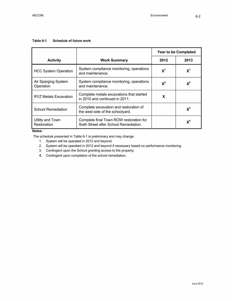
AECOM Environment
June 2012
6-2
Table 6-1 Schedule of future work
Activity Work Summary
Year to be Completed
2012 2013
HCC System Operation System compliance monitoring, operations and maintenance. X1 X1
Air Sparging System Operation
System compliance monitoring, operations and maintenance. X2 X2
RYZ Metals Excavation Complete metals excavations that started in 2010 and continued in 2011. X
School Remediation Complete excavation and restoration of the west side of the schoolyard. X3
Utility and Town Restoration
Complete final Town ROW restoration for Sixth Street after School Remediation. X4
Notes: The schedule presented in Table 6-1 is preliminary and may change.
1. System will be operated in 2012 and beyond. 2. System will be operated in 2012 and beyond if necessary based on performance monitoring. 3. Contingent upon the School granting access to the property. 4. Contingent upon completion of the school remediation.
AECOM Environment
June 2012
7-1
7.0 Summary and Conclusions
During the period starting January 1, 2011 and ending December 31, 2011, personnel from AECOM oversaw the remediation activities at the Former BNSF Maintenance and Fueling Facility in Skykomish, Washington on behalf of BNSF.
Some of the approximate quantities pertinent to 2011 Skykomish remediation activities include the following:
• 9,900 gallons of oil was recovered during excavation activities and delivered to a recycling facility.
• 43,144 tons of impacted soil was excavated and transported to the Rabanco Subtitle D landfill in Roosevelt, Washington for disposal. Approximately 5,000 tons remain on-site for transportation and off-site disposal which is anticipated to occur after 2011.
• 783,150 gallons of construction water were treated at the on-site CWTS and discharged per the NPDES permit.
• 290,800 gallons of SHF stormwater run-off was collected and transported off-site for treatment.
The Levee West End and Bridge Area in-water remediation was completed in 2011. A kayak ramp was installed immediately west of the bridge.
Soil remediation was completed on the west end of the playground at the School Property in 2011; however, much of the playground property remains unremediated. BNSF is in active negotiations with the Skykomish School District to obtain access for the remaining School Property Remediation (i.e., schoolyard and School Building). Consequently the construction schedule is undetermined at this time.
Metals-impacted soils were excavated from most of the areas in the RYZ. The remaining remediation areas are expected to be completed in a future construction season.
TPH-impacted soils were excavated from several areas in the RYZ. TPH-impacted excavations were completed and those areas were backfilled and restored.
Residual TPH-impacted soil on the Scisco and Austin properties was removed.
The public ROW and private properties within the NWDZ (Robinson, Scisco, Austin, Sky River Inn and Shawver) were restored and returned to the property owners in accordance with their respective access agreements.
Final remaining underground utilities were installed per the CPS, including the Town sanitary sewer system consisting of new septic tanks and piping, a JUT that undergrounded consolidated electrical, cable and telephone services. The as-built drawings are provided in Appendix H.
The planned 2011 work was substantially completed with the exception of the School and some RYZ shallow metals excavations on the rail yard as noted earlier in this report. Work completed in 2012 or later will be described in addenda to this report.
8-1
8.0 References
AECOM 2012a, Draft 2011 Annual Hydraulic Control and Containment System Operations Report. Prepared for the BNSF Railway Company by AECOM Environment. Seattle, Washington. February 17, 2012.
AECOM 2012b, Draft 2011 Annual Air Sparging System Report. Prepared for the BNSF Railway Company by AECOM Environment. Seattle, Washington. February 3, 2012.
AECOM 2011. 2011 Stormwater Pollution Prevention Plan . Prepared for the BNSF Railway Company by ENSR Corporation, Seattle, WA. May 10, 2011.
AECOM 2010a, 2010 Engineering Design Report, Prepared for AECOM Environment by Northwest Archaeological Associates, Inc. Seattle, Washington. May 3, 2010.
AECOM 2010b, 2010 Compliance Monitoring Plan Update, Prepared for the BNSF Railway Company by AECOM Environment. Seattle, Washington. June 28, 2010.
AECOM 2010c, 2010 Construction Plans and Specifications, Prepared for the BNSF Railway Company by AECOM Environment. Seattle, Washington. March 29, 2010.
AECOM 2010d. Operations and Maintenance Manual for Water Treatment System. Prepared for the BNSF Railway Company by ENSR Corporation, Seattle, WA. April 2010.
AECOM 2009. 2008 Skykomish Remediation As-Built Completion Report. Skykomish, Washington. Prepared for the BNSF Railway Company by AECOM Environment. Seattle, Washington. August 2009.
Ecology 2011, NPDES permit (Permit No. WA-003212-3), Prepared for BNSF Railway Company by the Washington State Department of Ecology, Bellevue, Washington. June 21, 2011.
Ecology 2007a, Cleanup Action Plan for BNSF Former Maintenance and Fueling Facility, Skykomish, Washington. Prepared for BNSF Railway Company by Washington State Department of Ecology. October 2007.
Ecology 2007b, Consent Decree, BNSF Former Maintenance and Fueling Facility, State of Washington King County Superior Court. Skykomish, Washington. October, 2007.
NWAA 2010. Archaeological Resources Monitoring and Discovery Plan. Prepared for AECOM Environment by Northwest Archaeological Associates, Inc. Seattle, Washington. February 2010.
RETEC 2008, Master Engineering Design Report; BNSF Former Maintenance and Fueling Facility, Skykomish, Washington. Prepared for the BNSF Railway Company by the RETEC Group, Inc, Seattle, Washington. January 2008.
Strider 2011, 2011 Technical Execution Plan, Prepared for BNSF Railway Company by Strider Construction Co, Inc, Bellingham, Washington. June 17, 2011.


Tables

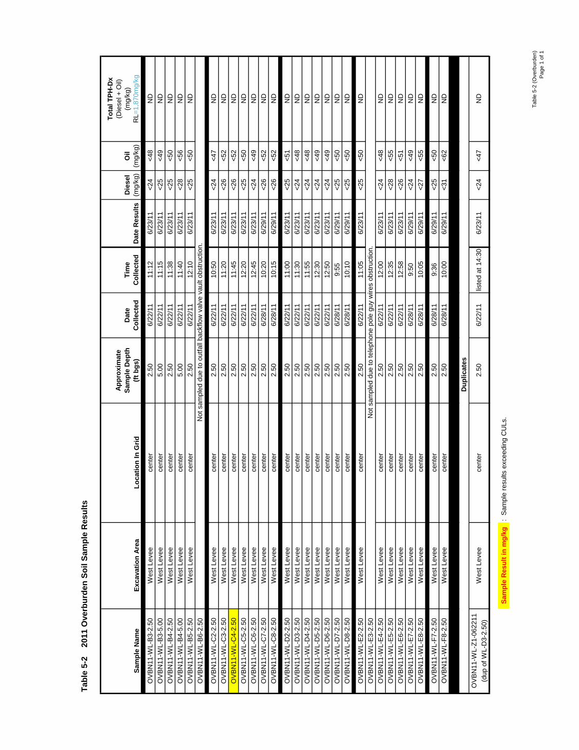
Tabl
e 5-
2 (O
verb
urde
n)P
age
1 of
1
Sam
ple
Nam
eEx
cava
tion
Area
Loca
tion
In G
rid
Appr
oxim
ate
Sam
ple
Dep
th
(ft b
gs)
Dat
e C
olle
cted
Tim
e C
olle
cted
Dat
e R
esul
tsD
iese
l
(m
g/kg
)O
il
(mg/
kg)
Tota
l TPH
-Dx
(Die
sel +
Oil)
(mg/
kg)
R
L=1,
870m
g/kg
OV
BN
11-W
L-B
3-2.
50W
est L
evee
cent
er2.
506/
22/1
111
:12
6/23
/11
<24
<48
ND
OV
BN
11-W
L-B
3-5.
00W
est L
evee
cent
er5.
006/
22/1
111
:15
6/23
/11
<25
<49
ND
OV
BN
11-W
L-B
4-2.
50W
est L
evee
cent
er2.
506/
22/1
111
:38
6/23
/11
<25
<50
ND
OV
BN
11-W
L-B
4-5.
00W
est L
evee
cent
er5.
006/
22/1
111
:40
6/23
/11
<28
<56
ND
OV
BN
11-W
L-B
5-2.
50W
est L
evee
cent
er2.
506/
22/1
112
:10
6/23
/11
<25
<50
ND
OV
BN
11-W
L-B
6-2.
50
OV
BN
11-W
L-C
2-2.
50W
est L
evee
cent
er2.
506/
22/1
110
:50
6/23
/11
<24
<47
ND
OV
BN
11-W
L-C
3-2.
50W
est L
evee
cent
er2.
506/
22/1
111
:20
6/23
/11
<26
<52
ND
OV
BN
11-W
L-C
4-2.
50W
est L
evee
cent
er2.
506/
22/1
111
:45
6/23
/11
<26
<52
ND
OV
BN
11-W
L-C
5-2.
50W
est L
evee
cent
er2.
506/
22/1
112
:20
6/23
/11
<25
<50
ND
OV
BN
11-W
L-C
6-2.
50W
est L
evee
cent
er2.
506/
22/1
112
:45
6/23
/11
<24
<49
ND
OV
BN
11-W
L-C
7-2.
50W
est L
evee
cent
er2.
506/
28/1
110
:20
6/29
/11
<26
<52
ND
OV
BN
11-W
L-C
8-2.
50W
est L
evee
cent
er2.
506/
28/1
110
:15
6/29
/11
<26
<52
ND
OV
BN
11-W
L-D
2-2.
50W
est L
evee
cent
er2.
506/
22/1
111
:00
6/23
/11
<25
<51
ND
OV
BN
11-W
L-D
3-2.
50W
est L
evee
cent
er2.
506/
22/1
111
:30
6/23
/11
<24
<48
ND
OV
BN
11-W
L-D
4-2.
50W
est L
evee
cent
er2.
506/
22/1
111
:55
6/23
/11
<24
<48
ND
OV
BN
11-W
L-D
5-2.
50W
est L
evee
cent
er2.
506/
22/1
112
:30
6/23
/11
<24
<49
ND
OV
BN
11-W
L-D
6-2.
50W
est L
evee
cent
er2.
506/
22/1
112
:50
6/23
/11
<24
<49
ND
OV
BN
11-W
L-D
7-2.
50W
est L
evee
cent
er2.
506/
28/1
19:
556/
29/1
1<2
5<5
0N
DO
VB
N11
-WL-
D8-
2.50
Wes
t Lev
eece
nter
2.50
6/28
/11
10:1
06/
29/1
1<2
5<5
0N
D
OV
BN
11-W
L-E
2-2.
50W
est L
evee
cent
er2.
506/
22/1
111
:05
6/23
/11
<25
<50
ND
OV
BN
11-W
L-E
3-2.
50O
VB
N11
-WL-
E4-
2.50
Wes
t Lev
eece
nter
2.50
6/22
/11
12:0
06/
23/1
1<2
4<4
8N
DO
VB
N11
-WL-
E5-
2.50
Wes
t Lev
eece
nter
2.50
6/22
/11
12:3
56/
23/1
1<2
8<5
5N
DO
VB
N11
-WL-
E6-
2.50
Wes
t Lev
eece
nter
2.50
6/22
/11
12:5
86/
23/1
1<2
6<5
1N
DO
VB
N11
-WL-
E7-
2.50
Wes
t Lev
eece
nter
2.50
6/28
/11
9:50
6/29
/11
<24
<49
ND
OV
BN
11-W
L-E
8-2.
50W
est L
evee
cent
er2.
506/
28/1
110
:05
6/29
/11
<27
<55
ND
OV
BN
11-W
L-F7
-2.5
0W
est L
evee
cent
er2.
506/
28/1
19:
366/
29/1
1<2
5<5
0N
DO
VB
N11
-WL-
F8-2
.50
Wes
t Lev
eece
nter
2.50
6/28
/11
10:0
06/
29/1
1<3
1<6
2N
D
OV
BN
11-W
L-Z1
-062
211
(dup
of W
L-D
3-2.
50)
Sam
ple
Res
ult i
n m
g/kg
: S
ampl
e re
sults
exc
eedi
ng C
ULs
.
Tabl
e 5-
2
2011
Ove
rbur
den
Soil
Sam
ple
Res
ults
Dup
licat
es
Wes
t Lev
eece
nter
2.50
6/22
/11
liste
d at
14:
306/
23/1
1<2
4<4
7N
D
Not
sam
pled
due
to te
leph
one
pole
guy
wire
s ob
stru
ctio
n.
Not
sam
pled
due
to o
utfa
ll ba
ckflo
w v
alve
vau
lt ob
stru
ctio
n.
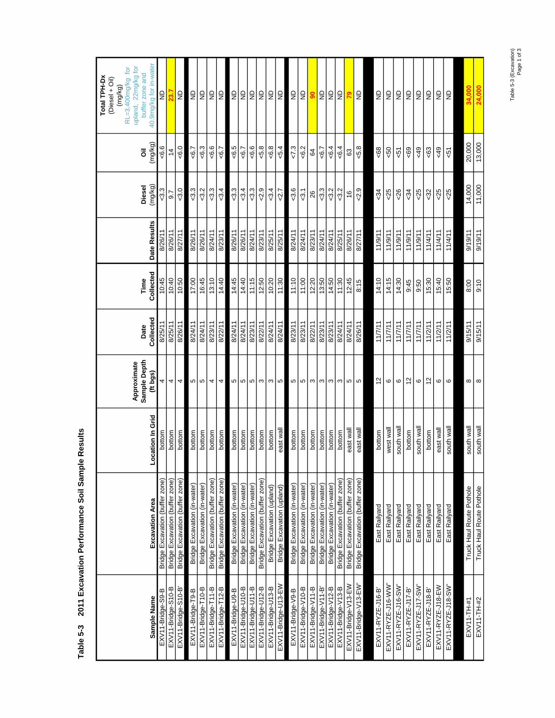
Tabl
e 5-
3 (E
xcav
atio
n)P
age
1 of
3
Sam
ple
Nam
eEx
cava
tion
Area
Loca
tion
In G
rid
Appr
oxim
ate
Sam
ple
Dep
th
(ft b
gs)
Dat
e C
olle
cted
Tim
e C
olle
cted
Dat
e R
esul
tsD
iese
l
(m
g/kg
)O
il
(mg/
kg)
Tota
l TPH
-Dx
(Die
sel +
Oil)
(mg/
kg)
RL=
3,40
0mg/
kg f
or
upla
nd,
22m
g/kg
for
buffe
r zon
e an
d 40
.9m
g/kg
for i
n-w
ater
EXV
11-B
ridge
-S9-
BB
ridge
Exc
avat
ion
(buf
fer z
one)
botto
m4
8/25
/11
10:4
58/
26/1
1<3
.3<6
.6N
DE
XV11
-Brid
ge-S
10-B
Brid
ge E
xcav
atio
n (b
uffe
r zon
e)bo
ttom
48/
25/1
110
:40
8/26
/11
9.7
1423
.7E
XV11
-Brid
ge-S
10-B
'B
ridge
Exc
avat
ion
(buf
fer z
one)
botto
m4
8/26
/11
10:5
08/
27/1
1<3
.0<6
.0N
D
EXV
11-B
ridge
-T9-
BB
ridge
Exc
avat
ion
(in-w
ater
)bo
ttom
58/
24/1
117
:00
8/26
/11
<3.3
<6.7
ND
EXV
11-B
ridge
-T10
-BB
ridge
Exc
avat
ion
(in-w
ater
)bo
ttom
58/
24/1
116
:45
8/26
/11
<3.2
<6.3
ND
EXV
11-B
ridge
-T11
-BB
ridge
Exc
avat
ion
(buf
fer z
one)
botto
m4
8/23
/11
13:1
08/
24/1
1<3
.3<6
.6N
DE
XV11
-Brid
ge-T
12-B
Brid
ge E
xcav
atio
n (b
uffe
r zon
e)bo
ttom
48/
22/1
114
:40
8/23
/11
<3.4
<6.7
ND
EXV
11-B
ridge
-U9-
BB
ridge
Exc
avat
ion
(in-w
ater
)bo
ttom
58/
24/1
114
:45
8/26
/11
<3.3
<6.5
ND
EXV
11-B
ridge
-U10
-BB
ridge
Exc
avat
ion
(in-w
ater
)bo
ttom
58/
24/1
114
:40
8/26
/11
<3.4
<6.7
ND
EXV
11-B
ridge
-U11
-BB
ridge
Exc
avat
ion
(in-w
ater
)bo
ttom
58/
23/1
111
:15
8/24
/11
<3.3
<6.6
ND
EXV
11-B
ridge
-U12
-BB
ridge
Exc
avat
ion
(buf
fer z
one)
botto
m3
8/22
/11
12:5
08/
23/1
1<2
.9<5
.8N
DE
XV11
-Brid
ge-U
13-B
Brid
ge E
xcav
atio
n (u
plan
d)bo
ttom
38/
24/1
110
:20
8/25
/11
<3.4
<6.8
ND
EXV
11-B
ridge
-U13
-EW
Brid
ge E
xcav
atio
n (u
plan
d)ea
st w
all
58/
24/1
111
:30
8/25
/11
<2.7
<5.4
ND
EXV
11-B
ridge
-V9-
BB
ridge
Exc
avat
ion
(in-w
ater
)bo
ttom
58/
23/1
111
:10
8/24
/11
<3.6
<7.3
ND
EXV
11-B
ridge
-V10
-BB
ridge
Exc
avat
ion
(in-w
ater
)bo
ttom
58/
23/1
111
:00
8/24
/11
<3.1
<6.2
ND
EXV
11-B
ridge
-V11
-BB
ridge
Exc
avat
ion
(in-w
ater
)bo
ttom
38/
22/1
112
:20
8/23
/11
2664
90E
XV11
-Brid
ge-V
11-B
'B
ridge
Exc
avat
ion
(in-w
ater
)bo
ttom
38/
23/1
113
:50
8/24
/11
<3.3
<6.7
ND
EXV
11-B
ridge
-V12
-BB
ridge
Exc
avat
ion
(in-w
ater
)bo
ttom
38/
23/1
114
:50
8/24
/11
<3.2
<6.4
ND
EXV
11-B
ridge
-V13
-BB
ridge
Exc
avat
ion
(buf
fer z
one)
botto
m3
8/24
/11
11:3
08/
25/1
1<3
.2<6
.4N
DE
XV11
-Brid
ge-V
13-E
WB
ridge
Exc
avat
ion
(buf
fer z
one)
east
wal
l5
8/24
/11
12:4
58/
26/1
116
6379
EXV
11-B
ridge
-V13
-EW
'B
ridge
Exc
avat
ion
(buf
fer z
one)
east
wal
l5
8/26
/11
8:15
8/27
/11
<2.9
<5.8
ND
EXV
11-R
YZE
-J16
-B'
Eas
t Rai
lyar
dbo
ttom
1211
/7/1
114
:10
11/9
/11
<34
<68
ND
EXV
11-R
YZE
-J16
-WW
'E
ast R
aily
ard
wes
t wal
l6
11/7
/11
14:1
511
/9/1
1<2
5<5
0N
DE
XV11
-RY
ZE-J
16-S
W'
Eas
t Rai
lyar
dso
uth
wal
l6
11/7
/11
14:3
011
/9/1
1<2
6<5
1N
DE
XV11
-RY
ZE-J
17-B
'E
ast R
aily
ard
botto
m12
11/7
/11
9:45
11/9
/11
<34
<69
ND
EXV
11-R
YZE
-J17
-SW
'E
ast R
aily
ard
sout
h w
all
611
/7/1
19:
5011
/9/1
1<2
5<4
9N
DE
XV11
-RY
ZE-J
18-B
'E
ast R
aily
ard
botto
m12
11/2
/11
15:3
011
/4/1
1<3
2<6
3N
DE
XV11
-RY
ZE-J
18-E
WE
ast R
aily
ard
east
wal
l6
11/2
/11
15:4
011
/4/1
1<2
5<4
9N
DE
XV11
-RY
ZE-J
18-S
W'
Eas
t Rai
lyar
dso
uth
wal
l6
11/2
/11
15:5
011
/4/1
1<2
5<5
1N
D
EXV
11-T
H-#
1Tr
uck
Hau
l Rou
te P
otho
leso
uth
wal
l8
9/15
/11
8:00
9/19
/11
14,0
0020
,000
34,0
00E
XV11
-TH
-#2
Truc
k H
aul R
oute
Pot
hole
sout
h w
all
89/
15/1
19:
109/
19/1
111
,000
13,0
0024
,000
Tabl
e 5-
3
2011
Exc
avat
ion
Perf
orm
ance
Soi
l Sam
ple
Res
ults
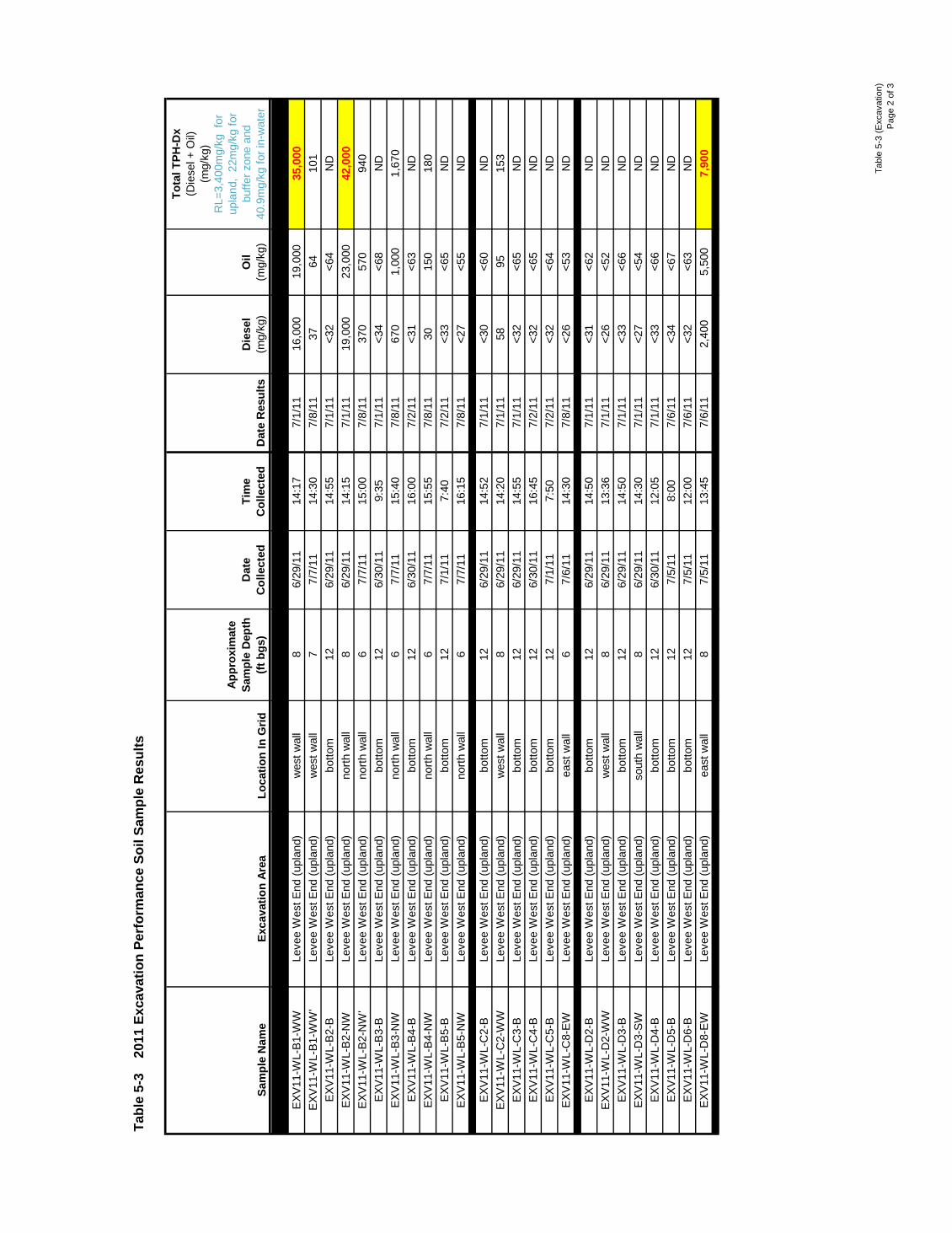
Tabl
e 5-
3 (E
xcav
atio
n)P
age
2 of
3
Sam
ple
Nam
eEx
cava
tion
Area
Loca
tion
In G
rid
Appr
oxim
ate
Sam
ple
Dep
th
(ft b
gs)
Dat
e C
olle
cted
Tim
e C
olle
cted
Dat
e R
esul
tsD
iese
l
(m
g/kg
)O
il
(mg/
kg)
Tota
l TPH
-Dx
(Die
sel +
Oil)
(mg/
kg)
RL=
3,40
0mg/
kg f
or
upla
nd,
22m
g/kg
for
buffe
r zon
e an
d 40
.9m
g/kg
for i
n-w
ater
Tabl
e 5-
3
2011
Exc
avat
ion
Perf
orm
ance
Soi
l Sam
ple
Res
ults
EXV
11-W
L-B
1-W
WLe
vee
Wes
t End
(upl
and)
wes
t wal
l8
6/29
/11
14:1
77/
1/11
16,0
0019
,000
35,0
00E
XV11
-WL-
B1-
WW
'Le
vee
Wes
t End
(upl
and)
wes
t wal
l7
7/7/
1114
:30
7/8/
1137
6410
1E
XV11
-WL-
B2-
BLe
vee
Wes
t End
(upl
and)
botto
m12
6/29
/11
14:5
57/
1/11
<32
<64
ND
EXV
11-W
L-B
2-N
WLe
vee
Wes
t End
(upl
and)
north
wal
l8
6/29
/11
14:1
57/
1/11
19,0
0023
,000
42,0
00E
XV11
-WL-
B2-
NW
'Le
vee
Wes
t End
(upl
and)
north
wal
l6
7/7/
1115
:00
7/8/
1137
057
094
0E
XV11
-WL-
B3-
BLe
vee
Wes
t End
(upl
and)
botto
m12
6/30
/11
9:35
7/1/
11<3
4<6
8N
DE
XV11
-WL-
B3-
NW
Leve
e W
est E
nd (u
plan
d)no
rth w
all
67/
7/11
15:4
07/
8/11
670
1,00
01,
670
EXV
11-W
L-B
4-B
Leve
e W
est E
nd (u
plan
d)bo
ttom
126/
30/1
116
:00
7/2/
11<3
1<6
3N
DE
XV11
-WL-
B4-
NW
Leve
e W
est E
nd (u
plan
d)no
rth w
all
67/
7/11
15:5
57/
8/11
3015
018
0E
XV11
-WL-
B5-
BLe
vee
Wes
t End
(upl
and)
botto
m12
7/1/
117:
407/
2/11
<33
<65
ND
EXV
11-W
L-B
5-N
WLe
vee
Wes
t End
(upl
and)
north
wal
l6
7/7/
1116
:15
7/8/
11<2
7<5
5N
D
EXV
11-W
L-C
2-B
Leve
e W
est E
nd (u
plan
d)bo
ttom
126/
29/1
114
:52
7/1/
11<3
0<6
0N
DE
XV11
-WL-
C2-
WW
Leve
e W
est E
nd (u
plan
d)w
est w
all
86/
29/1
114
:20
7/1/
1158
9515
3E
XV11
-WL-
C3-
BLe
vee
Wes
t End
(upl
and)
botto
m12
6/29
/11
14:5
57/
1/11
<32
<65
ND
EXV
11-W
L-C
4-B
Leve
e W
est E
nd (u
plan
d)bo
ttom
126/
30/1
116
:45
7/2/
11<3
2<6
5N
DE
XV11
-WL-
C5-
BLe
vee
Wes
t End
(upl
and)
botto
m12
7/1/
117:
507/
2/11
<32
<64
ND
EXV
11-W
L-C
8-E
WLe
vee
Wes
t End
(upl
and)
east
wal
l6
7/6/
1114
:30
7/8/
11<2
6<5
3N
DLe
vee
Wes
t End
(upl
and)
EXV
11-W
L-D
2-B
Leve
e W
est E
nd (u
plan
d)bo
ttom
126/
29/1
114
:50
7/1/
11<3
1<6
2N
DE
XV11
-WL-
D2-
WW
Leve
e W
est E
nd (u
plan
d)w
est w
all
86/
29/1
113
:36
7/1/
11<2
6<5
2N
DE
XV11
-WL-
D3-
BLe
vee
Wes
t End
(upl
and)
botto
m12
6/29
/11
14:5
07/
1/11
<33
<66
ND
EXV
11-W
L-D
3-S
WLe
vee
Wes
t End
(upl
and)
sout
h w
all
86/
29/1
114
:30
7/1/
11<2
7<5
4N
DE
XV11
-WL-
D4-
BLe
vee
Wes
t End
(upl
and)
botto
m12
6/30
/11
12:0
57/
1/11
<33
<66
ND
EXV
11-W
L-D
5-B
Leve
e W
est E
nd (u
plan
d)bo
ttom
127/
5/11
8:00
7/6/
11<3
4<6
7N
DE
XV11
-WL-
D6-
BLe
vee
Wes
t End
(upl
and)
botto
m12
7/5/
1112
:00
7/6/
11<3
2<6
3N
DE
XV11
-WL-
D8-
EW
Leve
e W
est E
nd (u
plan
d)ea
st w
all
87/
5/11
13:4
57/
6/11
2,40
05,
500
7,90
0
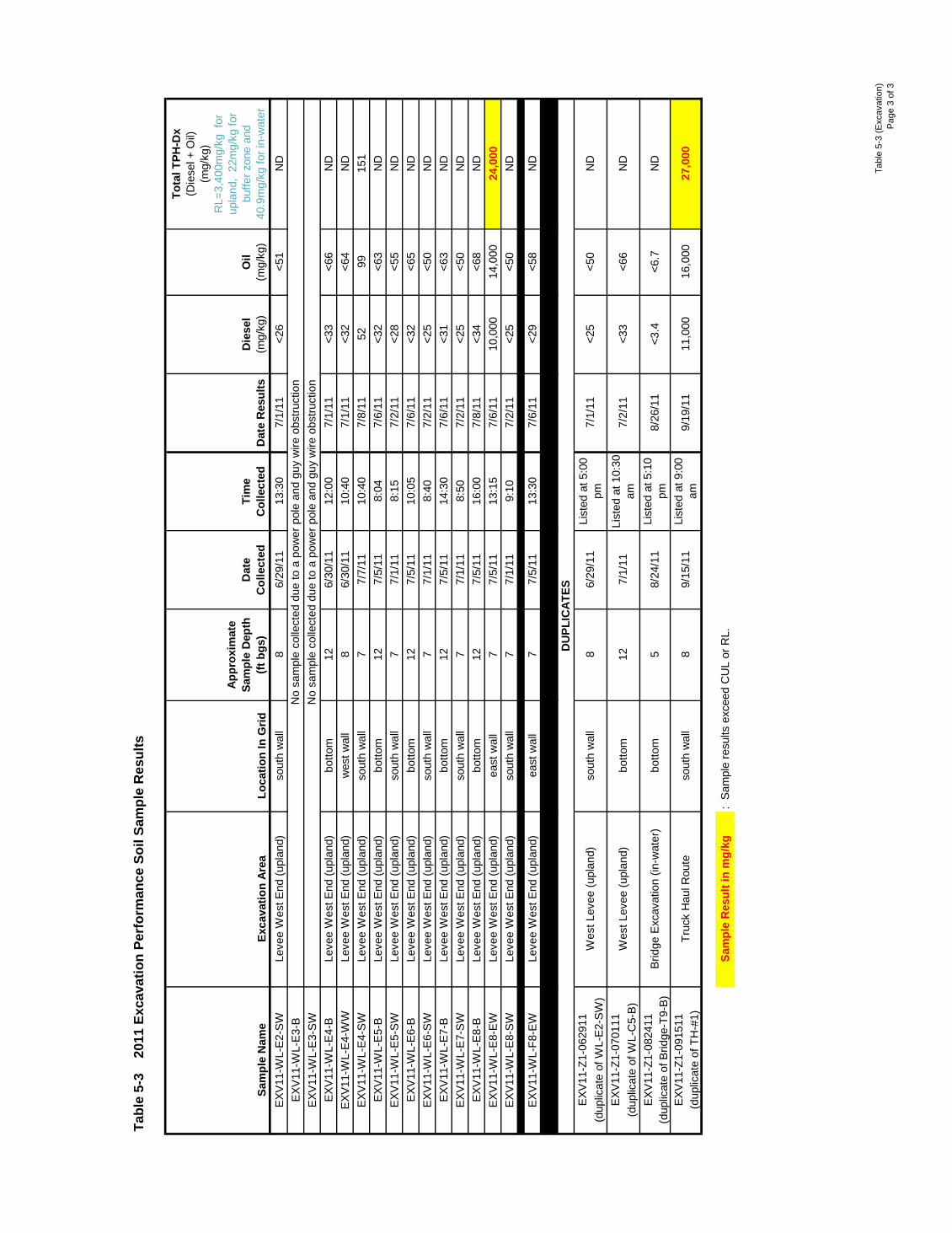
Tabl
e 5-
3 (E
xcav
atio
n)P
age
3 of
3
Sam
ple
Nam
eEx
cava
tion
Area
Loca
tion
In G
rid
Appr
oxim
ate
Sam
ple
Dep
th
(ft b
gs)
Dat
e C
olle
cted
Tim
e C
olle
cted
Dat
e R
esul
tsD
iese
l
(m
g/kg
)O
il
(mg/
kg)
Tota
l TPH
-Dx
(Die
sel +
Oil)
(mg/
kg)
RL=
3,40
0mg/
kg f
or
upla
nd,
22m
g/kg
for
buffe
r zon
e an
d 40
.9m
g/kg
for i
n-w
ater
Tabl
e 5-
3
2011
Exc
avat
ion
Perf
orm
ance
Soi
l Sam
ple
Res
ults
EXV
11-W
L-E
2-S
WLe
vee
Wes
t End
(upl
and)
sout
h w
all
86/
29/1
113
:30
7/1/
11<2
6<5
1N
DE
XV11
-WL-
E3-
BE
XV11
-WL-
E3-
SW
EXV
11-W
L-E
4-B
Leve
e W
est E
nd (u
plan
d)bo
ttom
126/
30/1
112
:00
7/1/
11<3
3<6
6N
DE
XV11
-WL-
E4-
WW
Leve
e W
est E
nd (u
plan
d)w
est w
all
86/
30/1
110
:40
7/1/
11<3
2<6
4N
DE
XV11
-WL-
E4-
SW
Leve
e W
est E
nd (u
plan
d)so
uth
wal
l7
7/7/
1110
:40
7/8/
1152
9915
1E
XV11
-WL-
E5-
BLe
vee
Wes
t End
(upl
and)
botto
m12
7/5/
118:
047/
6/11
<32
<63
ND
EXV
11-W
L-E
5-S
WLe
vee
Wes
t End
(upl
and)
sout
h w
all
77/
1/11
8:15
7/2/
11<2
8<5
5N
DE
XV11
-WL-
E6-
BLe
vee
Wes
t End
(upl
and)
botto
m12
7/5/
1110
:05
7/6/
11<3
2<6
5N
DE
XV11
-WL-
E6-
SW
Leve
e W
est E
nd (u
plan
d)so
uth
wal
l7
7/1/
118:
407/
2/11
<25
<50
ND
EXV
11-W
L-E
7-B
Leve
e W
est E
nd (u
plan
d)bo
ttom
127/
5/11
14:3
07/
6/11
<31
<63
ND
EXV
11-W
L-E
7-S
WLe
vee
Wes
t End
(upl
and)
sout
h w
all
77/
1/11
8:50
7/2/
11<2
5<5
0N
DE
XV11
-WL-
E8-
BLe
vee
Wes
t End
(upl
and)
botto
m12
7/5/
1116
:00
7/8/
11<3
4<6
8N
DE
XV11
-WL-
E8-
EW
Leve
e W
est E
nd (u
plan
d)ea
st w
all
77/
5/11
13:1
57/
6/11
10,0
0014
,000
24,0
00E
XV11
-WL-
E8-
SW
Leve
e W
est E
nd (u
plan
d)so
uth
wal
l7
7/1/
119:
107/
2/11
<25
<50
ND
EXV
11-W
L-F8
-EW
Leve
e W
est E
nd (u
plan
d)ea
st w
all
77/
5/11
13:3
07/
6/11
<29
<58
ND
EXV
11-Z
1-06
2911
(dup
licat
e of
WL-
E2-
SW
)E
XV11
-Z1-
0701
11(d
uplic
ate
of W
L-C
5-B
)E
XV11
-Z1-
0824
11(d
uplic
ate
of B
ridge
-T9-
B)
EXV
11-Z
1-09
1511
(dup
licat
e of
TH
-#1)
Sam
ple
Res
ult i
n m
g/kg
: S
ampl
e re
sults
exc
eed
CU
L or
RL.
27,0
00
<33
<66
ND
8/26
/11
ND
<3.4
<6.7
7/2/
11
9/19
/11
11,0
0016
,000
Wes
t Lev
ee (u
plan
d)so
uth
wal
l6/
29/1
1Li
sted
at 5
:00
pm7/
1/11
<25
<50
ND
8
No
sam
ple
colle
cted
due
to a
pow
er p
ole
and
guy
wire
obs
truct
ion
No
sam
ple
colle
cted
due
to a
pow
er p
ole
and
guy
wire
obs
truct
ion
DU
PLIC
ATES
Wes
t Lev
ee (u
plan
d)bo
ttom
List
ed a
t 5:1
0 pm
12
Brid
ge E
xcav
atio
n (in
-wat
er)
botto
m5
7/1/
11Li
sted
at 1
0:30
am
8/24
/11
Truc
k H
aul R
oute
sout
h w
all
89/
15/1
1Li
sted
at 9
:00
am
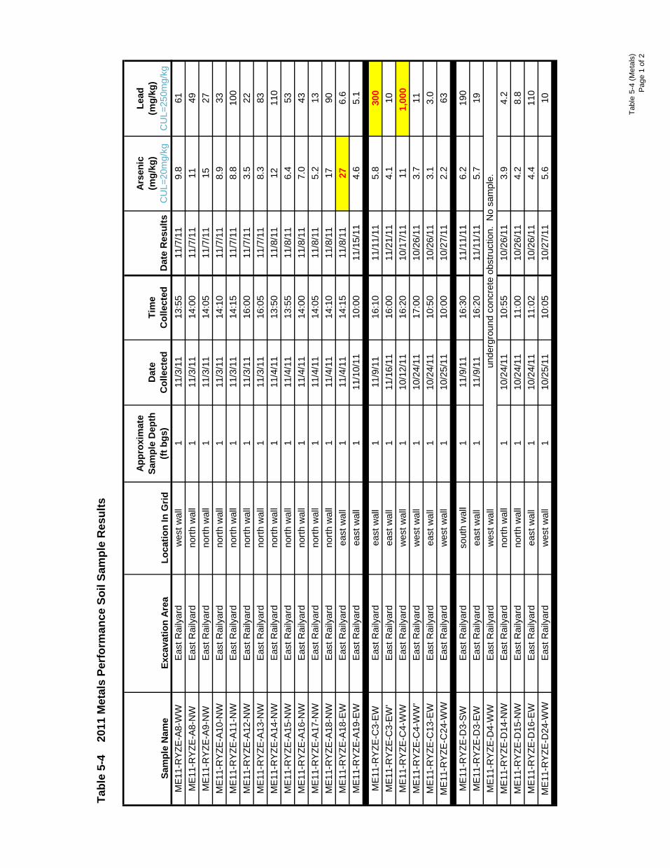
Tabl
e 5-
4 (M
etal
s)P
age
1 of
2
Sam
ple
Nam
eEx
cava
tion
Area
Loca
tion
In G
rid
Appr
oxim
ate
Sam
ple
Dep
th
(ft b
gs)
Dat
e C
olle
cted
Tim
e C
olle
cted
Dat
e R
esul
ts
Arse
nic
(m
g/kg
) C
UL=
20m
g/kg
Lead
(mg/
kg)
CU
L=25
0mg/
kgM
E11-
RYZ
E-A8
-WW
East
Rai
lyar
dw
est w
all
111
/3/1
113
:55
11/7
/11
9.8
61M
E11-
RYZ
E-A8
-NW
East
Rai
lyar
dno
rth w
all
111
/3/1
114
:00
11/7
/11
1149
ME1
1-R
YZE-
A9-N
WEa
st R
aily
ard
north
wal
l1
11/3
/11
14:0
511
/7/1
115
27M
E11-
RYZ
E-A1
0-N
WEa
st R
aily
ard
north
wal
l1
11/3
/11
14:1
011
/7/1
18.
933
ME1
1-R
YZE-
A11-
NW
East
Rai
lyar
dno
rth w
all
111
/3/1
114
:15
11/7
/11
8.8
100
ME1
1-R
YZE-
A12-
NW
East
Rai
lyar
dno
rth w
all
111
/3/1
116
:00
11/7
/11
3.5
22M
E11-
RYZ
E-A1
3-N
WEa
st R
aily
ard
north
wal
l1
11/3
/11
16:0
511
/7/1
18.
383
ME1
1-R
YZE-
A14-
NW
East
Rai
lyar
dno
rth w
all
111
/4/1
113
:50
11/8
/11
1211
0M
E11-
RYZ
E-A1
5-N
WEa
st R
aily
ard
north
wal
l1
11/4
/11
13:5
511
/8/1
16.
453
ME1
1-R
YZE-
A16-
NW
East
Rai
lyar
dno
rth w
all
111
/4/1
114
:00
11/8
/11
7.0
43M
E11-
RYZ
E-A1
7-N
WEa
st R
aily
ard
north
wal
l1
11/4
/11
14:0
511
/8/1
15.
213
ME1
1-R
YZE-
A18-
NW
East
Rai
lyar
dno
rth w
all
111
/4/1
114
:10
11/8
/11
1790
ME1
1-R
YZE-
A18-
EWEa
st R
aily
ard
east
wal
l1
11/4
/11
14:1
511
/8/1
127
6.6
ME1
1-R
YZE-
A19-
EWEa
st R
aily
ard
east
wal
l1
11/1
0/11
10:0
011
/15/
114.
65.
1
ME1
1-R
YZE-
C3-
EWEa
st R
aily
ard
east
wal
l1
11/9
/11
16:1
011
/11/
115.
830
0M
E11-
RYZ
E-C
3-EW
'Ea
st R
aily
ard
east
wal
l1
11/1
6/11
16:0
011
/21/
114.
110
ME1
1-R
YZE-
C4-
WW
East
Rai
lyar
dw
est w
all
110
/12/
1116
:20
10/1
7/11
111,
000
ME1
1-R
YZE-
C4-
WW
'Ea
st R
aily
ard
wes
t wal
l1
10/2
4/11
17:0
010
/26/
113.
711
ME1
1-R
YZE-
C13
-EW
East
Rai
lyar
dea
st w
all
110
/24/
1110
:50
10/2
6/11
3.1
3.0
ME1
1-R
YZE-
C24
-WW
East
Rai
lyar
dw
est w
all
110
/25/
1110
:00
10/2
7/11
2.2
63
ME1
1-R
YZE-
D3-
SWEa
st R
aily
ard
sout
h w
all
111
/9/1
116
:30
11/1
1/11
6.2
190
ME1
1-R
YZE-
D3-
EWEa
st R
aily
ard
east
wal
l1
11/9
/11
16:2
011
/11/
115.
719
ME1
1-R
YZE-
D4-
WW
East
Rai
lyar
dw
est w
all
ME1
1-R
YZE-
D14
-NW
East
Rai
lyar
dno
rth w
all
110
/24/
1110
:55
10/2
6/11
3.9
4.2
ME1
1-R
YZE-
D15
-NW
East
Rai
lyar
dno
rth w
all
110
/24/
1111
:00
10/2
6/11
4.2
8.8
ME1
1-R
YZE-
D16
-EW
East
Rai
lyar
dea
st w
all
110
/24/
1111
:02
10/2
6/11
4.4
110
ME1
1-R
YZE-
D24
-WW
East
Rai
lyar
dw
est w
all
110
/25/
1110
:05
10/2
7/11
5.6
10
Tabl
e 5-
4
2011
Met
als
Perf
orm
ance
Soi
l Sam
ple
Res
ults
unde
rgro
und
conc
rete
obs
truct
ion.
No
sam
ple.
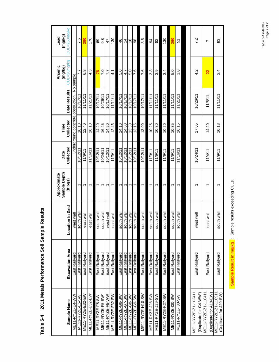
Tabl
e 5-
4 (M
etal
s)P
age
2 of
2
Sam
ple
Nam
eEx
cava
tion
Area
Loca
tion
In G
rid
Appr
oxim
ate
Sam
ple
Dep
th
(ft b
gs)
Dat
e C
olle
cted
Tim
e C
olle
cted
Dat
e R
esul
ts
Arse
nic
(m
g/kg
) C
UL=
20m
g/kg
Lead
(mg/
kg)
CU
L=25
0mg/
kg
Tabl
e 5-
4
2011
Met
als
Perf
orm
ance
Soi
l Sam
ple
Res
ults
ME1
1-R
YZE-
E4-W
WEa
st R
aily
ard
wes
t wal
lM
E11-
RYZ
E-E5
-SW
East
Rai
lyar
dso
uth
wal
l1
10/1
2/11
16:1
010
/17/
117.
77.
6M
E11-
RYZ
E-E3
2-EW
East
Rai
lyar
dea
st w
all
111
/9/1
112
:40
11/1
1/11
6.8
290
ME1
1-R
YZE-
E32-
EW'
East
Rai
lyar
dea
st w
all
111
/16/
1116
:10
11/2
1/11
4.3
170
ME1
1-R
YZE-
F5-S
WEa
st R
aily
ard
sout
h w
all
110
/12/
1114
:20
10/1
7/11
7869
ME1
1-R
YZE-
F5-S
W'
East
Rai
lyar
dso
uth
wal
l1
10/2
4/11
16:4
510
/26/
117.
09.
8M
E11-
RYZ
E-F5
-WW
East
Rai
lyar
dw
est w
all
110
/12/
1114
:50
10/1
7/11
7.7
47M
E11-
RYZ
E-F3
2-EW
East
Rai
lyar
dea
st w
all
111
/9/1
112
:45
11/1
1/11
4.1
130
ME1
1-R
YZE-
G6-
SWEa
st R
aily
ard
sout
h w
all
110
/12/
1114
:10
10/1
7/11
5.0
46M
E11-
RYZ
E-G
7-SW
East
Rai
lyar
dso
uth
wal
l1
10/1
2/11
14:0
010
/17/
114.
714
ME1
1-R
YZE-
G8-
SWEa
st R
aily
ard
sout
h w
all
110
/12/
1113
:30
10/1
7/11
5.0
18M
E11-
RYZ
E-G
9-SW
East
Rai
lyar
dso
uth
wal
l1
10/1
2/11
13:1
510
/17/
117.
698
ME1
1-R
YZE-
H10
-SW
East
Rai
lyar
dso
uth
wal
l1
10/1
2/11
13:0
010
/17/
117.
63.
5
ME1
1-R
YZE-
J28-
SWEa
st R
aily
ard
sout
h w
all
111
/9/1
110
:25
11/1
1/11
3.3
94M
E11-
RYZ
E-J2
9-SW
East
Rai
lyar
dso
uth
wal
l1
11/9
/11
10:3
011
/11/
112.
982
M
E11-
RYZ
E-K2
7-SW
East
Rai
lyar
dso
uth
wal
l1
11/9
/11
10:2
011
/11/
113.
413
0
ME1
1-R
YZE-
I30-
SWEa
st R
aily
ard
sout
h w
all
111
/9/1
110
:35
11/1
1/11
5.0
260
ME1
1-R
YZE-
I30-
SW'
East
Rai
lyar
dso
uth
wal
l1
11/1
6/11
16:1
511
/21/
111.
851
ME1
1-R
YZE-
Z1-1
0241
1(D
uplic
ate
for C
4-W
W')
ME1
1-R
YZE-
Z1-1
1041
1(D
uplic
ate
for A
18-E
W)
ME1
1-R
YZE-
Z1-1
1091
1(D
uplic
ate
for J
29-S
W)
Sam
ple
Res
ult i
n m
g/kg
: Sa
mpl
e re
sults
exc
eedi
ng C
ULs
.
11/1
1/11
2.4
83Ea
st R
aily
ard
sout
h w
all
111
/9/1
110
:18
East
Rai
lyar
dw
est w
all
110
/24/
1117
:05
10/2
6/11
4.2
7.2
unde
rgro
und
conc
rete
obs
truct
ion.
No
sam
ple.
14:2
011
/8/1
122
7Ea
st R
aily
ard
east
wal
l1
11/4
/11
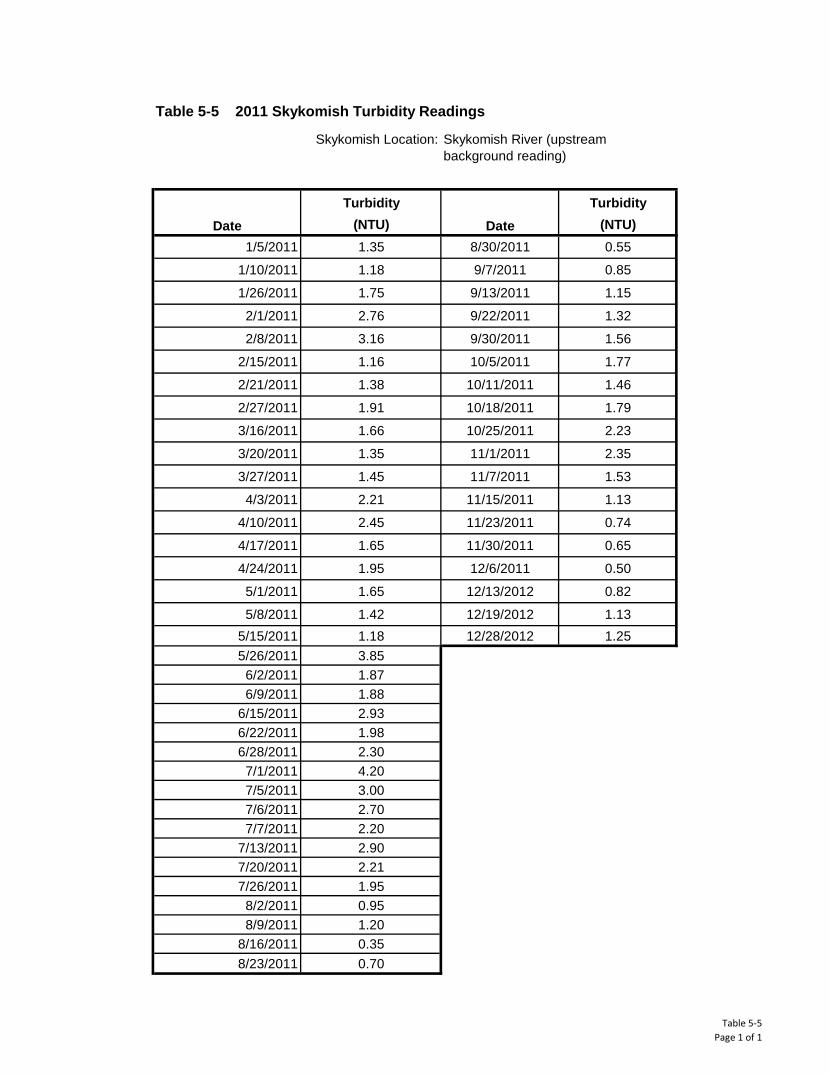
Table 5-5Page 1 of 1
Turbidity Turbidity(NTU) (NTU)
1/5/2011 1.35 8/30/2011 0.55
1/10/2011 1.18 9/7/2011 0.85
1/26/2011 1.75 9/13/2011 1.15
2/1/2011 2.76 9/22/2011 1.32
2/8/2011 3.16 9/30/2011 1.56
2/15/2011 1.16 10/5/2011 1.77
2/21/2011 1.38 10/11/2011 1.46
2/27/2011 1.91 10/18/2011 1.79
3/16/2011 1.66 10/25/2011 2.23
3/20/2011 1.35 11/1/2011 2.35
3/27/2011 1.45 11/7/2011 1.53
4/3/2011 2.21 11/15/2011 1.13
4/10/2011 2.45 11/23/2011 0.74
4/17/2011 1.65 11/30/2011 0.65
4/24/2011 1.95 12/6/2011 0.50
5/1/2011 1.65 12/13/2012 0.82
5/8/2011 1.42 12/19/2012 1.135/15/2011 1.18 12/28/2012 1.255/26/2011 3.85
6/2/2011 1.876/9/2011 1.88
6/15/2011 2.936/22/2011 1.986/28/2011 2.30
7/1/2011 4.207/5/2011 3.007/6/2011 2.707/7/2011 2.20
7/13/2011 2.907/20/2011 2.217/26/2011 1.95
8/2/2011 0.958/9/2011 1.20
8/16/2011 0.358/23/2011 0.70
Table 5-5 2011 Skykomish Turbidity Readings
Date Date
Skykomish Location:
Skykomish River (upstream background reading)
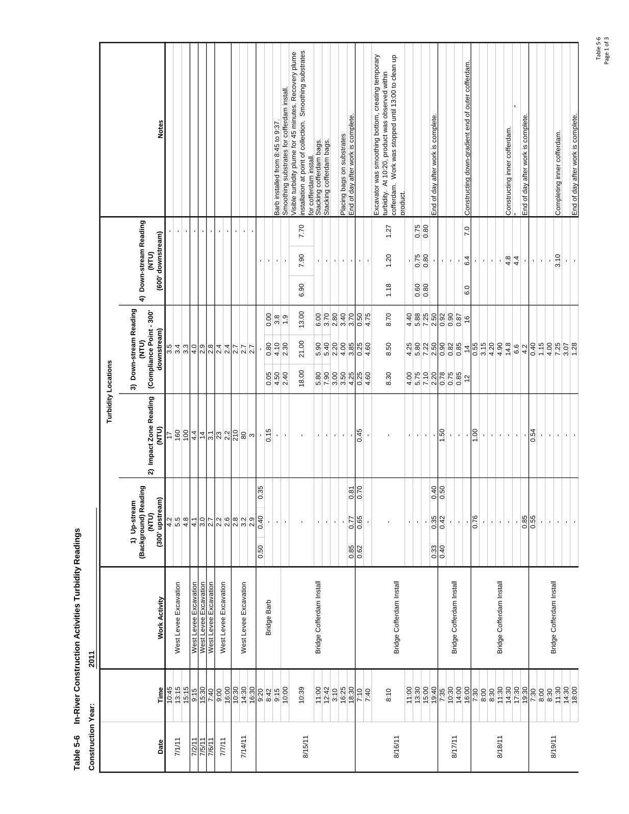
Tabl
e 5-
6Pa
ge 1
of 3
10:4
5-
13:1
5-
15:1
5-
7/2/
119:
15W
est L
evee
Exc
avat
ion
-7/
5/11
15:3
0W
est L
evee
Exc
avat
ion
-7/
6/11
7:40
Wes
t Lev
ee E
xcav
atio
n-
9:00
-16
:00
-10
:30
-14
:30
-16
:30
-9:
200.
500.
400.
358:
420.
050.
800.
009:
154.
504.
103.
8B
arb
inst
alle
d fro
m 8
:45
to 9
:37.
10:0
02.
402.
301.
9S
moo
thin
g su
bstra
tes
for c
offe
rdam
inst
all.
11:0
05.
805.
906.
00S
tack
ing
coffe
rdam
bag
s.12
:42
7.90
5.40
3.70
Sta
ckin
g co
fferd
am b
ags.
3:10
3.00
2.20
2.80
16:2
53.
504.
003.
40P
laci
ng b
ags
on s
ubst
rate
s18
:30
0.85
0.77
0.81
4.25
3.85
3.70
End
of d
ay a
fter w
ork
is c
ompl
ete.
7:10
0.62
0.65
0.70
0.25
0.25
0.50
7:40
4.60
4.60
4.75
8:10
8.30
8.50
8.70
1.18
1.20
1.27
Exc
avat
or w
as s
moo
thin
g bo
ttom
, cre
atin
g te
mpo
rary
tu
rbid
ity.
At 1
0:20
, pro
duct
was
obs
erve
d w
ithin
co
fferd
am.
Wor
k w
as s
topp
ed u
ntil
13:0
0 to
cle
an u
p pr
oduc
t.11
:00
4.00
4.25
4.40
13:3
05.
755.
805.
880.
600.
750.
7515
:00
7.10
7.22
7.25
0.80
0.80
0.80
19:4
00.
330.
350.
402.
202.
502.
50E
nd o
f day
afte
r wor
k is
com
plet
e.7:
350.
400.
420.
500.
780.
900.
9210
:30
0.75
0.82
0.90
14:0
00.
850.
850.
8716
:00
1214
166.
06.
47.
0C
onst
ruct
ing
dow
n-gr
adie
nt e
nd o
f out
er c
offe
rdam
.7:
308:
008:
3011
:30
14:3
0C
onst
ruct
ing
inne
r cof
ferd
am.
17:3
0"
"19
:30
End
of d
ay a
fter w
ork
is c
ompl
ete.
7:30
8:00
8:30
11:3
0C
ompl
etin
g in
ner c
offe
rdam
.14
:30
18:0
0E
nd o
f day
afte
r wor
k is
com
plet
e.
13.0
021
.00
--
Vis
ible
turb
idity
plu
me
for 4
5 m
inut
es. R
ecov
ery
plum
e in
stal
latio
n at
poi
nt o
f col
lect
ion.
Sm
ooth
ing
subs
trate
s fo
r cof
ferd
am in
stal
l.
-
7.70
7.90
6.90
- - -
- - -
- -
-
--
210
2.7
802.
73
Wes
t Lev
ee E
xcav
atio
n16
010
04.
4 - - - -
14.8
-3.
07
-0.
15 -
Tabl
e 5-
6
In-R
iver
Con
stru
ctio
n Ac
tiviti
es T
urbi
dity
Rea
ding
s
18.0
0-
-2.7
2.2
2.4
2.6
3.1
23 2.2 -
3.2
2.9
2.7
10:3
9
7/14
/11
Wes
t Lev
ee E
xcav
atio
n2.
8
Not
es
- - -
2.8
2.4
1) U
p-st
ream
(B
ackg
roun
d) R
eadi
ng
(NTU
)
(3
00' u
pstr
eam
)
Con
stru
ctio
n Ye
ar:
3) D
own-
stre
am R
eadi
ng
(NTU
) (C
ompl
ianc
e Po
int -
300
' do
wns
trea
m)
2011
Dat
eTi
me
Wor
k Ac
tivity
Turb
idity
Loc
atio
ns
2) I
mpa
ct Z
one
Rea
ding
(N
TU)
4) D
own-
stre
am R
eadi
ng
(NTU
)
(600
' dow
nstr
eam
)
5.5
4.0
4.1
3.0
142.
9
7/1/
113.
34.
8
173.
53.
44.
2
Brid
ge C
offe
rdam
Inst
all
Brid
ge B
arb
Brid
ge C
offe
rdam
Inst
all
Wes
t Lev
ee E
xcav
atio
n
8/16
/11
--
-
- --
-
- -
8/15
/11
7/7/
11
--
- --
0.45 - -
8/17
/11
Brid
ge C
offe
rdam
Inst
all
1.50
--
--
--
--
-
8/18
/11
Brid
ge C
offe
rdam
Inst
all
1.00
--
--
--
--
--
--
- --
0.55
0.76
3.15
4.20
-4.
90
8/19
/11
Brid
ge C
offe
rdam
Inst
all
0.55
0.54
0.40
--
-1.
15-
--
4.00
--
-7.
253.
10-
4.8
6.6
4.4
0.85
4.2
--
-1.
28-
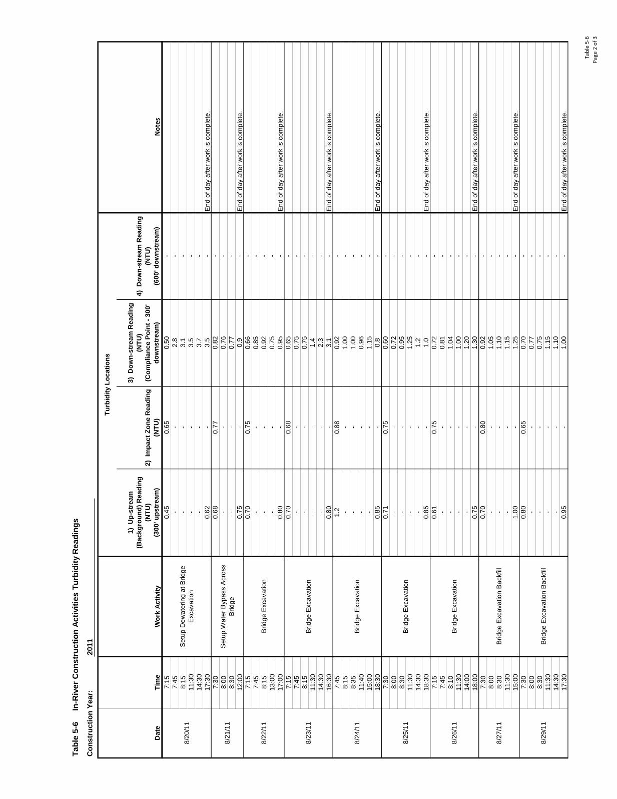
Tabl
e 5-
6Pa
ge 2
of 3
Tabl
e 5-
6
In-R
iver
Con
stru
ctio
n Ac
tiviti
es T
urbi
dity
Rea
ding
s
Not
es
1) U
p-st
ream
(B
ackg
roun
d) R
eadi
ng
(NTU
)
(3
00' u
pstr
eam
)
Con
stru
ctio
n Ye
ar:
3) D
own-
stre
am R
eadi
ng
(NTU
) (C
ompl
ianc
e Po
int -
300
' do
wns
trea
m)
2011
Dat
eTi
me
Wor
k Ac
tivity
Turb
idity
Loc
atio
ns
2) I
mpa
ct Z
one
Rea
ding
(N
TU)
4) D
own-
stre
am R
eadi
ng
(NTU
)
(600
' dow
nstr
eam
)7:
157:
458:
1511
:30
14:3
0
17:3
0E
nd o
f day
afte
r wor
k is
com
plet
e.7:
308:
008:
3012
:00
End
of d
ay a
fter w
ork
is c
ompl
ete.
7:15
7:45
8:15
13:0
017
:00
End
of d
ay a
fter w
ork
is c
ompl
ete.
7:15
7:45
8:15
11:3
014
:30
16
:30
End
of d
ay a
fter w
ork
is c
ompl
ete.
7:45
8:15
8:35
11:4
015
:00
18
:30
End
of d
ay a
fter w
ork
is c
ompl
ete.
7:30
8:00
8:30
11:3
014
:30
18
:30
End
of d
ay a
fter w
ork
is c
ompl
ete.
7:15
7:45
8:10
11:3
014
:00
18
:00
End
of d
ay a
fter w
ork
is c
ompl
ete.
7:30
8:00
8:30
11:3
015
:00
End
of d
ay a
fter w
ork
is c
ompl
ete.
7:30
8:00
8:30
11:3
014
:30
17
:30
End
of d
ay a
fter w
ork
is c
ompl
ete.
0.75
0.66 3.1
--
2.8
--
-3.
1
0.45
0.65
0.50
- -
0.75
-0.
9-
0.62
-3.
5-
--
3.5
--
-3.
7-
0.68
0.77
0.82
--
-0.
76-
--
0.77
-
8/20
/11
Set
up D
ewat
erin
g at
Brid
ge
Exc
avat
ion
8/22
/11
Brid
ge E
xcav
atio
n-
-0.
92-
--
0.75
-0.
80-
0.95
---
-0.
85-
0.70
8/21
/11
Set
up W
ater
Byp
ass
Acr
oss
Brid
ge
8/23
/11
Brid
ge E
xcav
atio
n
0.70
0.68
0.65
--
-0.
75-
--
0.75
--
-1.
4-
--
2.3
-0.
80-
-
8/24
/11
Brid
ge E
xcav
atio
n
1.2
0.88
0.92
--
-1.
00-
--
1.00
--
-0.
96-
--
1.15
-0.
85-
0.8
-
8/25
/11
Brid
ge E
xcav
atio
n
0.71
0.75
0.60
--
-0.
72-
--
0.95
--
-1.
25-
--
1.2
-0.
85-
1.0
-
8/26
/11
Brid
ge E
xcav
atio
n
0.61
0.75
0.72
--
-0.
81-
--
1.04
--
-1.
00-
--
1.20
-0.
75-
8/27
/11
Brid
ge E
xcav
atio
n B
ackf
ill
0.70
0.80
0.92
--
-1.
05-
--
1.10
--
-1.
15-
1.00
-1.
25-
1.30
-
--
1.15
--
-1.
10-
0.95
-
0.70
--
-0.
77-
--
0.75
- -
8/29
/11
Brid
ge E
xcav
atio
n B
ackf
ill
0.80
0.65
1.00
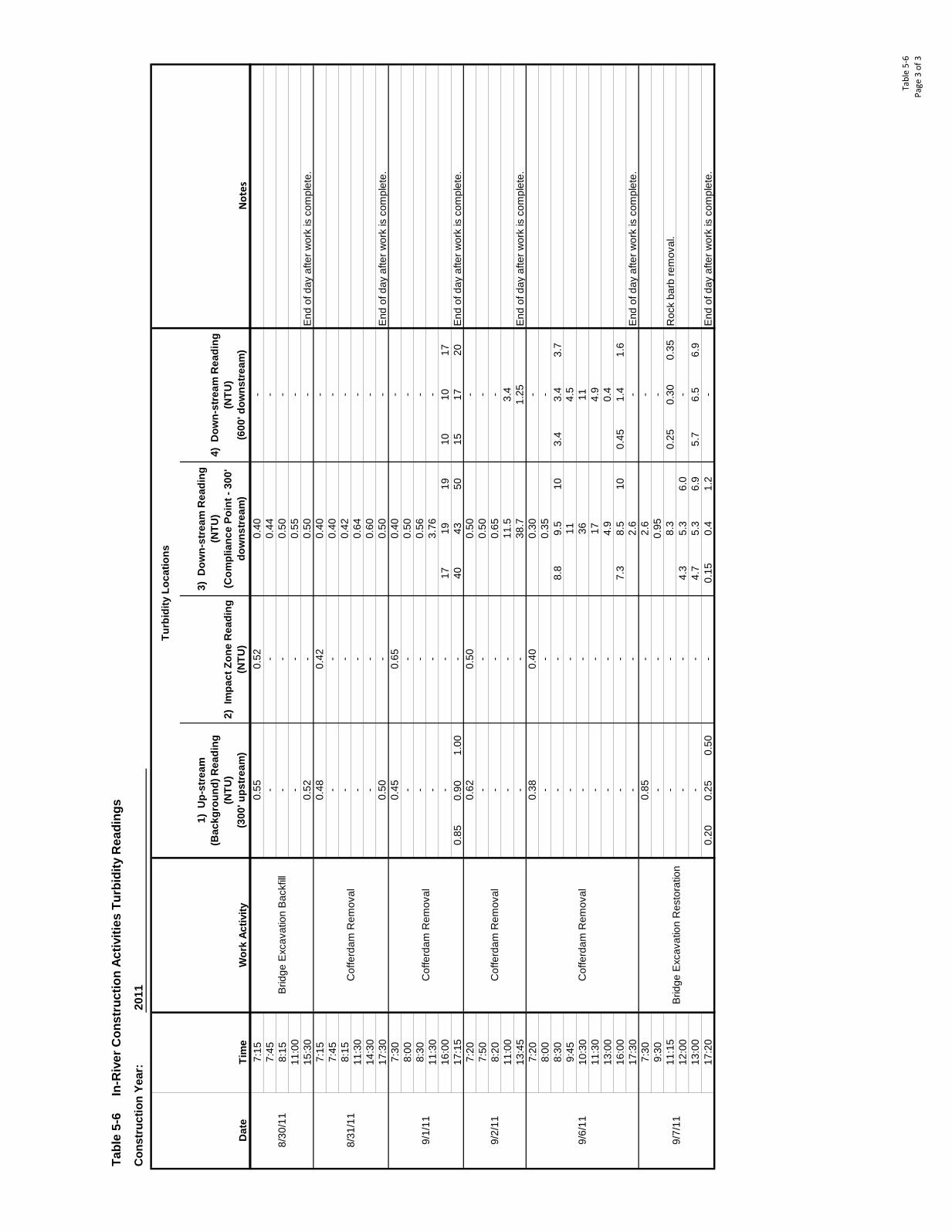
Tabl
e 5-
6Pa
ge 3
of 3
Tabl
e 5-
6
In-R
iver
Con
stru
ctio
n Ac
tiviti
es T
urbi
dity
Rea
ding
s
Not
es
1) U
p-st
ream
(B
ackg
roun
d) R
eadi
ng
(NTU
)
(3
00' u
pstr
eam
)
Con
stru
ctio
n Ye
ar:
3) D
own-
stre
am R
eadi
ng
(NTU
) (C
ompl
ianc
e Po
int -
300
' do
wns
trea
m)
2011
Dat
eTi
me
Wor
k Ac
tivity
Turb
idity
Loc
atio
ns
2) I
mpa
ct Z
one
Rea
ding
(N
TU)
4) D
own-
stre
am R
eadi
ng
(NTU
)
(600
' dow
nstr
eam
)7:
157:
458:
1511
:00
15:3
0E
nd o
f day
afte
r wor
k is
com
plet
e.7:
157:
458:
1511
:30
14:3
0
17:3
0E
nd o
f day
afte
r wor
k is
com
plet
e.7:
308:
008:
3011
:30
16:0
017
1919
1010
17
17:1
50.
850.
901.
0040
4350
1517
20E
nd o
f day
afte
r wor
k is
com
plet
e.7:
207:
508:
2011
:00
13:4
5E
nd o
f day
afte
r wor
k is
com
plet
e.7:
208:
008:
308.
89.
510
3.4
3.4
3.7
9:45
10:3
0
11:3
0
13:0
0
16:0
07.
38.
510
0.45
1.4
1.6
17
:30
End
of d
ay a
fter w
ork
is c
ompl
ete.
7:30
9:30
11:1
50.
250.
300.
35R
ock
barb
rem
oval
.12
:00
4.3
5.3
6.0
13:0
04.
75.
36.
95.
76.
56.
9
17:2
00.
200.
250.
500.
150.
41.
2E
nd o
f day
afte
r wor
k is
com
plet
e.
9/7/
11B
ridge
Exc
avat
ion
Res
tora
tion
0.85
-2.
6-
--
0.95
--
-8.
3-
--
-- -
-
4.9
0.4
--
3611
--
174.
9
0.38
0.40
0.30
-
9/6/
11C
offe
rdam
Rem
oval
--
0.35
--
--
-11
4.5
--
--
2.6
-
--
9/2/
11C
offe
rdam
Rem
oval
0.62
0.50
0.50
--
-0.
50-
--
0.65
--
-11
.53.
4-
-38
.71.
25
9/1/
11C
offe
rdam
Rem
oval
0.45
0.65
0.40
--
-0.
50-
--
0.56
--
-3.
76-
-- -
- ---
-0.
44-
--
0.50
-
8/31
/11
Cof
ferd
am R
emov
al
0.48
0.42
0.40
--
0.64
0.52
-0.
50
8/30
/11
Brid
ge E
xcav
atio
n B
ackf
ill
0.55
0.52
0.40
--
0.55
--
-0.
40-
--
0.42
- --
-0.
60-
0.50
-0.
50-

Figures

Appendices A – N (Note: All appendices are provided on the attached CD.) Appendix A Permits and Inspection Records Appendix B Well Decommissioning and
Construction Reports Appendix C TESC Reports Appendix D CWTS Operations Reports Appendix E Daily Construction Reports Appendix F Project Photographs Appendix G Contractor Submittals Appendix H As-Built Construction Drawings Appendix I Data Validation Reports Appendix J Analytical Reports Appendix K Biological Opinion Letter Appendix L Compaction Testing Results Appendix M Air and Noise Reports Appendix N Weather Data

Appendix A Permits and Inspection Records

Appendix B Well Decommissioning and Construction Reports


Appendix C TESC Reports

Appendix D CWTS Operations Reports


Appendix E Daily Construction Reports


Appendix F Project Photographs


Appendix G Contractor Submittals


Appendix H As-Built Construction Drawings

Appendix I Data Validation Report


Appendix J Analytical Reports


Appendix K Biological Opinion Letter


Appendix L Compaction Testing Results

Appendix M Air and Noise Reports

Appendix N Weather Data