Embed Size (px)
Citation preview

Transformer ProtectionMike KockottMarch, 2014
2014 Relay School
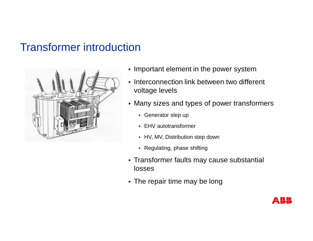
Transformer introduction
§ Important element in the power system
§ Interconnection link between two differentvoltage levels
§ Many sizes and types of power transformers§ Generator step up
§ EHV autotransformer
§ HV, MV, Distribution step down
§ Regulating, phase shifting
§ Transformer faults may cause substantiallosses
§ The repair time may be long
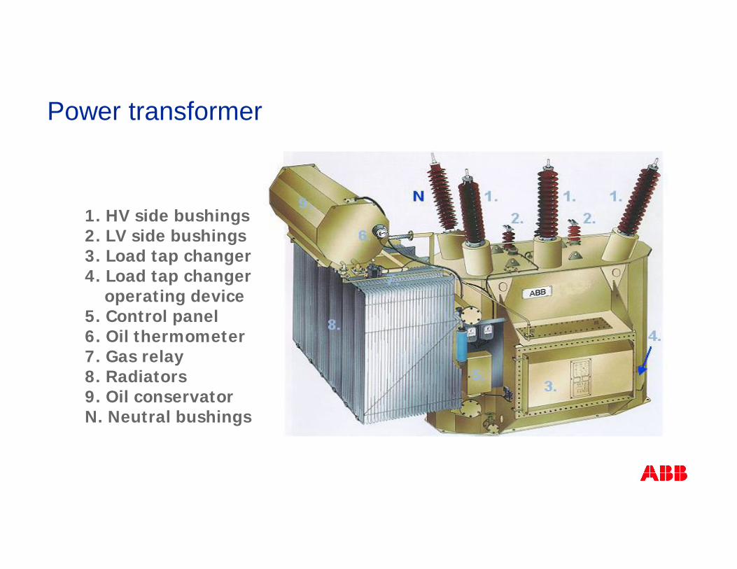
1. HV side bushings2. LV side bushings3. Load tap changer4. Load tap changer
operating device5. Control panel6. Oil thermometer7. Gas relay8. Radiators9. Oil conservatorN. Neutral bushings
Power transformer
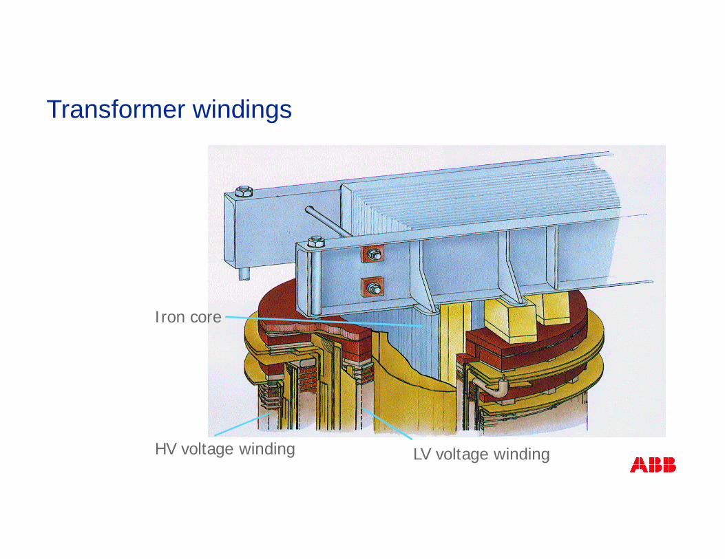
Iron core
HV voltage winding LV voltage winding
Transformer windings

Typical transformer protection application
§ 87T
§ 87N
§ 49
§ 24
§ 50/51/67
§ 51N/67N/51G
§ 59/59N/27
§ 50BF
§ 60F
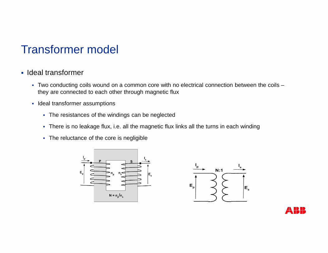
§ Ideal transformer§ Two conducting coils wound on a common core with no electrical connection between the coils –
they are connected to each other through magnetic flux
§ Ideal transformer assumptions
§ The resistances of the windings can be neglected
§ There is no leakage flux, i.e. all the magnetic flux links all the turns in each winding
§ The reluctance of the core is negligible
Transformer model
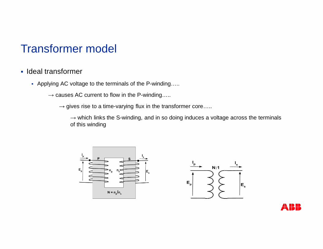
§ Ideal transformer§ Applying AC voltage to the terminals of the P-winding…..
→ causes AC current to flow in the P-winding…..
→ gives rise to a time-varying flux in the transformer core…..
→ which links the S-winding, and in so doing induces a voltage across the terminalsof this winding
Transformer model
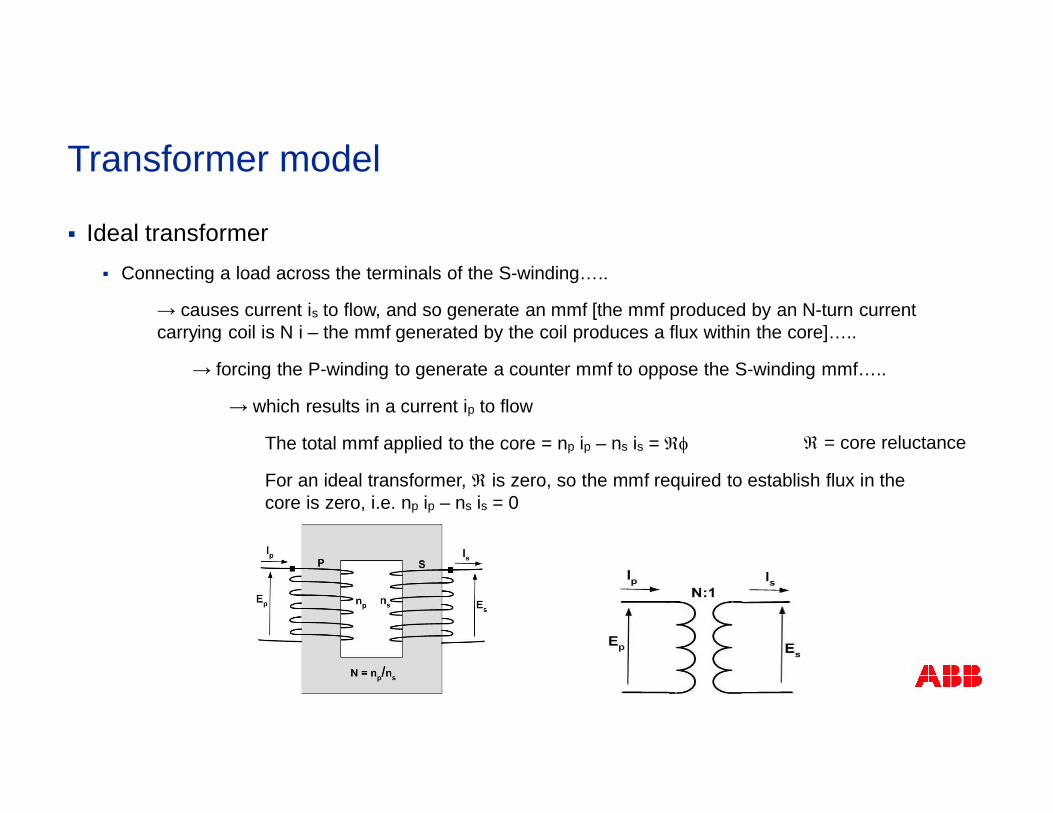
§ Ideal transformer§ Connecting a load across the terminals of the S-winding…..
→ causes current is to flow, and so generate an mmf [the mmf produced by an N-turn currentcarrying coil is N i – the mmf generated by the coil produces a flux within the core]…..
→ forcing the P-winding to generate a counter mmf to oppose the S-winding mmf…..
→ which results in a current ip to flow
The total mmf applied to the core = np ip – ns is = Âf
For an ideal transformer, Â is zero, so the mmf required to establish flux in thecore is zero, i.e. np ip – ns is = 0
Transformer model
 = core reluctance
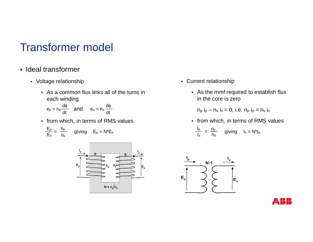
§ Current relationship
§ As the mmf required to establish fluxin the core is zero
np ip – ns is = 0, i.e. np ip = ns is
§ from which, in terms of RMS values
§ Ideal transformer§ Voltage relationship
§ As a common flux links all of the turns ineach winding
§ from which, in terms of RMS values
Transformer model
ep = npdfdt
es = nsdfdt
Ep
Es
np
ns=
and
IpIs
ns
np=giving Ep = N*Es giving Is = N*Ip
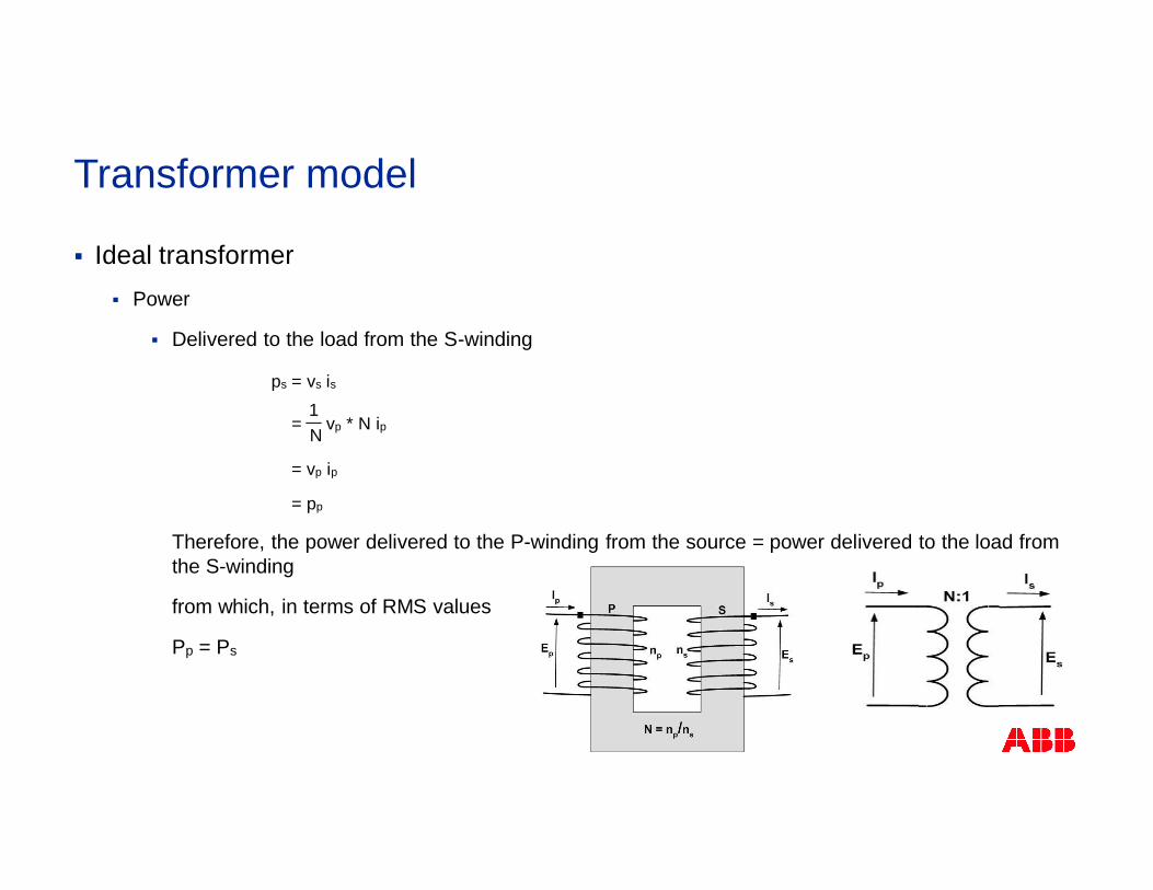
§ Ideal transformer§ Power
§ Delivered to the load from the S-winding
Therefore, the power delivered to the P-winding from the source = power delivered to the load fromthe S-winding
from which, in terms of RMS values
Pp = Ps
Transformer model
= vp * N ip1N
ps = vs is
= vp ip
= pp
§ Actual (non-ideal) transformer§ Resistive (I2R) losses (copper losses) occur in the P- and S-windings
§ Some leakage of flux occurs, i.e. not all the flux produced by the P-winding links the S-winding, andvice versa.
§ The core requires a finite amount of mmf for its magnetization
§ Hysteresis and eddy current losses cause power loss in transformer core
Transformer model
Transformer model
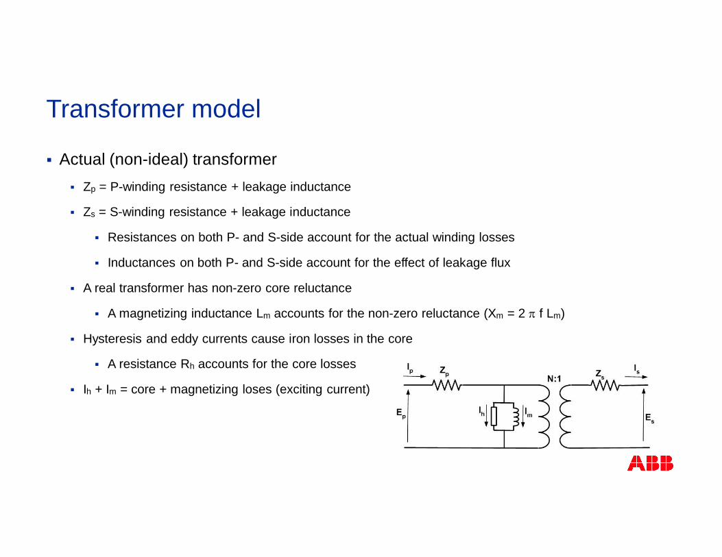
§ Actual (non-ideal) transformer§ Zp = P-winding resistance + leakage inductance
§ Zs = S-winding resistance + leakage inductance
§ Resistances on both P- and S-side account for the actual winding losses
§ Inductances on both P- and S-side account for the effect of leakage flux
§ A real transformer has non-zero core reluctance
§ A magnetizing inductance Lm accounts for the non-zero reluctance (Xm = 2 p f Lm)
§ Hysteresis and eddy currents cause iron losses in the core
§ A resistance Rh accounts for the core losses
§ Ih + Im = core + magnetizing loses (exciting current)
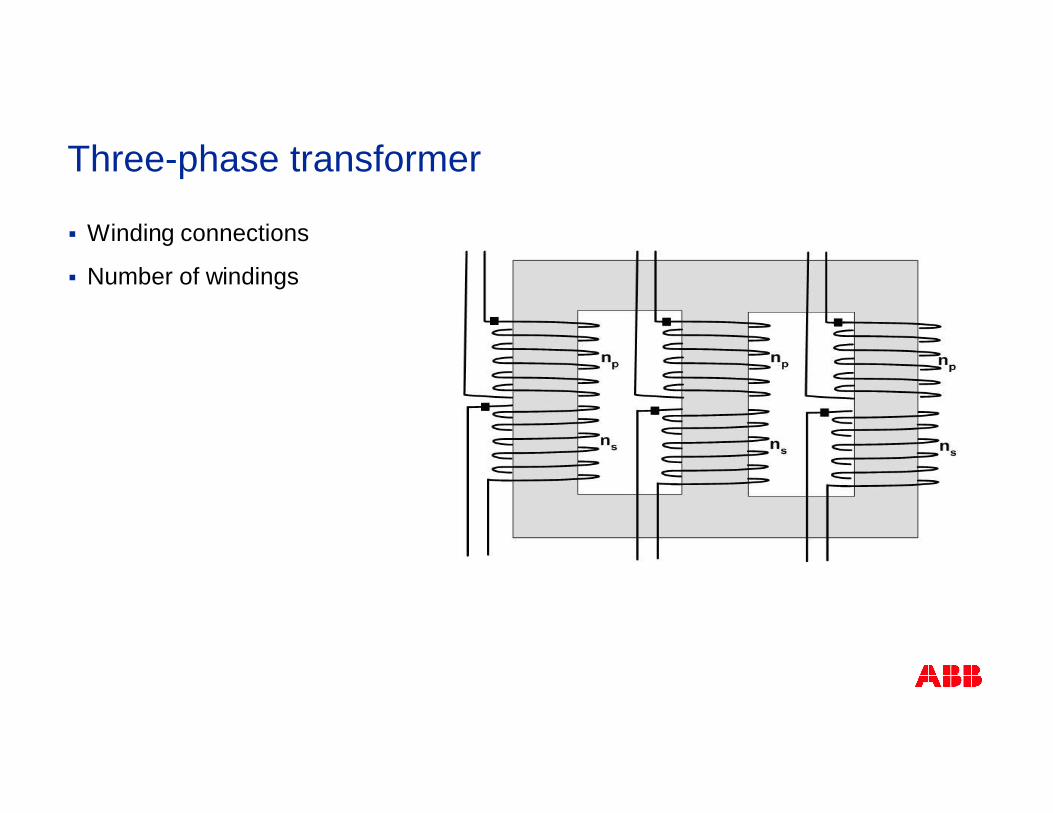
Three-phase transformer
§ Winding connections
§ Number of windings
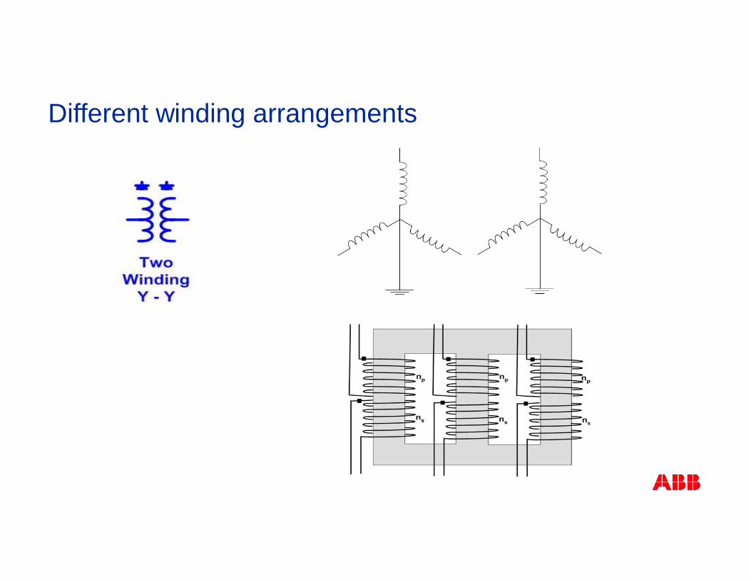
Different winding arrangements
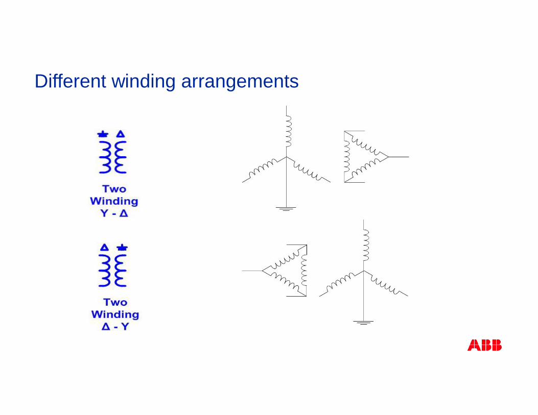
Different winding arrangements
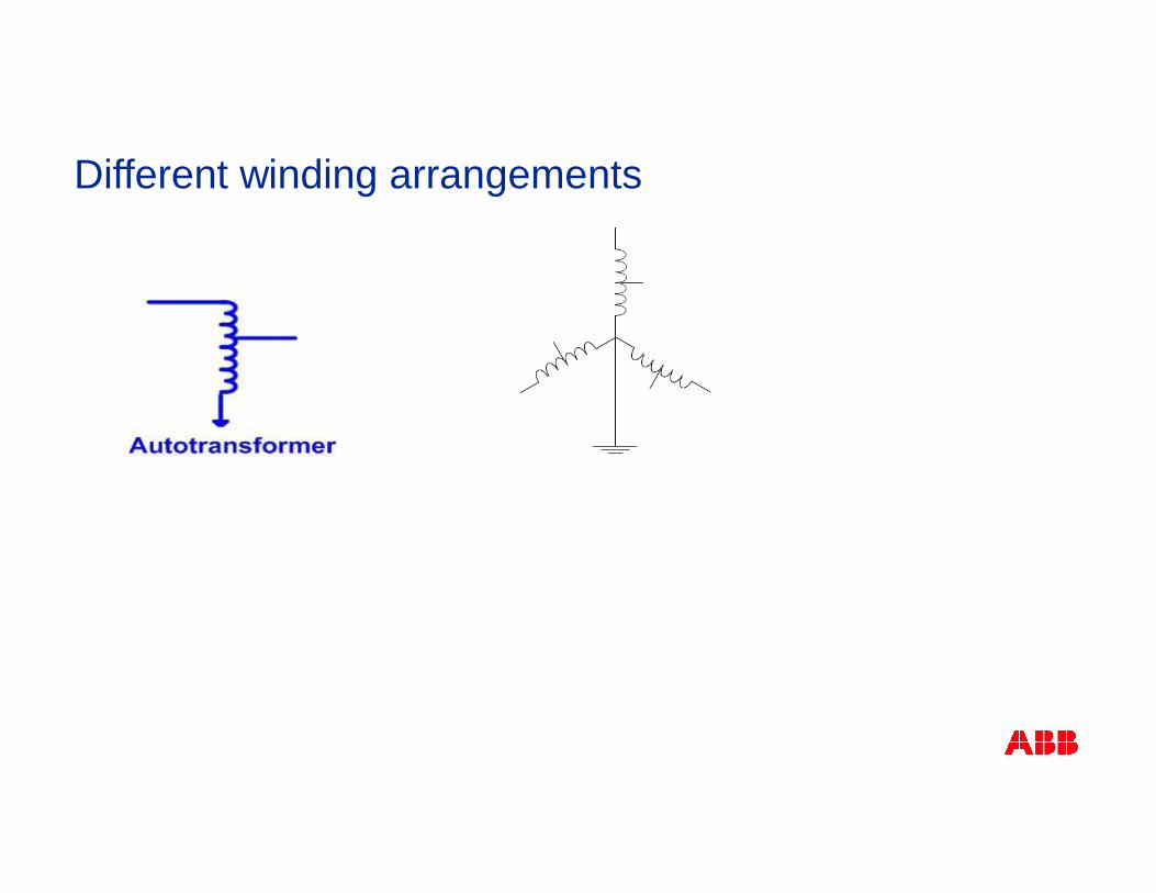
Different winding arrangements
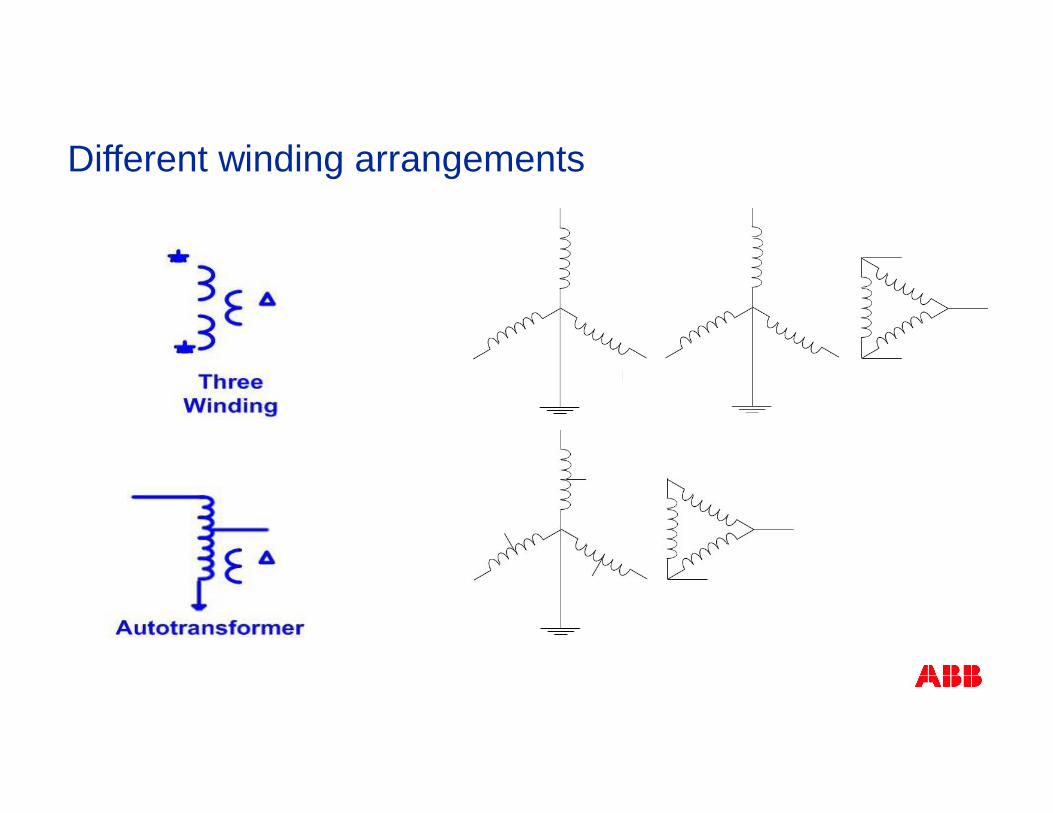
Different winding arrangements
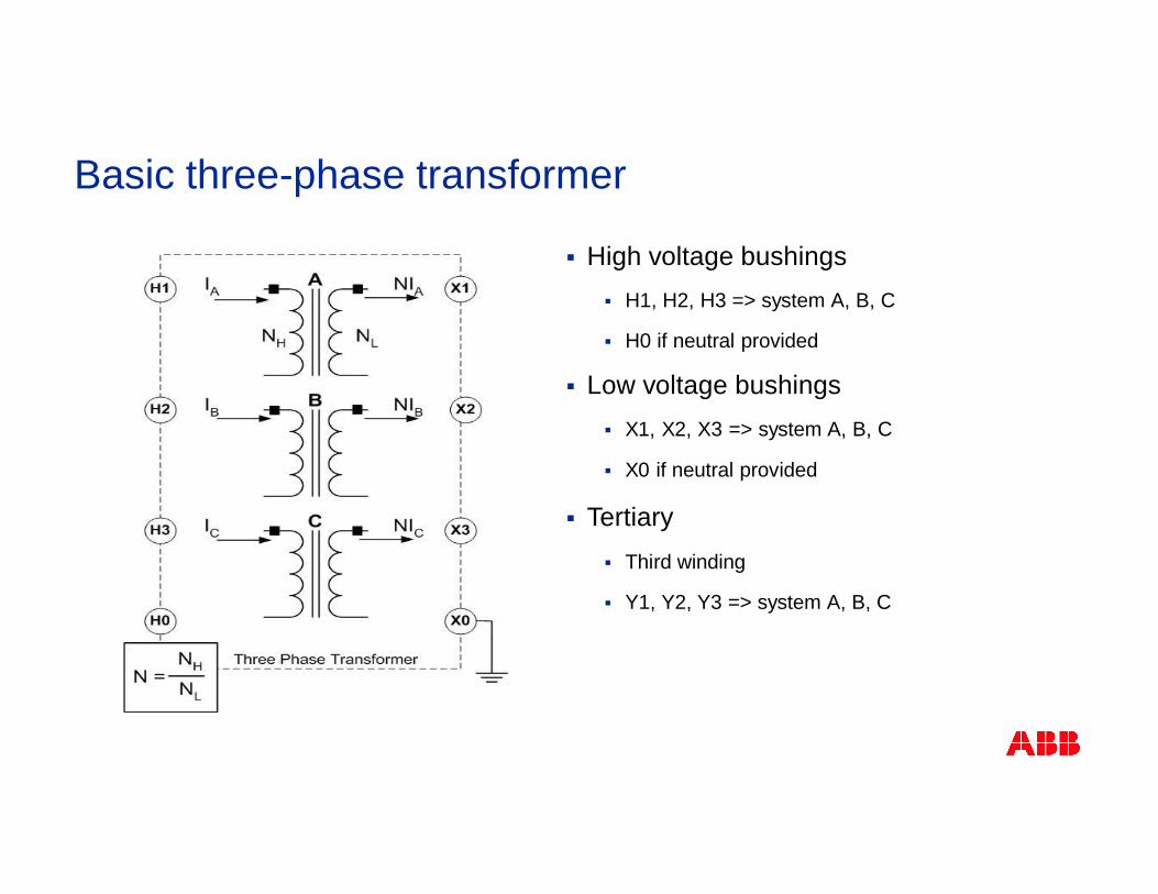
Basic three-phase transformer
§ High voltage bushings§ H1, H2, H3 => system A, B, C
§ H0 if neutral provided
§ Low voltage bushings§ X1, X2, X3 => system A, B, C
§ X0 if neutral provided
§ Tertiary§ Third winding
§ Y1, Y2, Y3 => system A, B, C
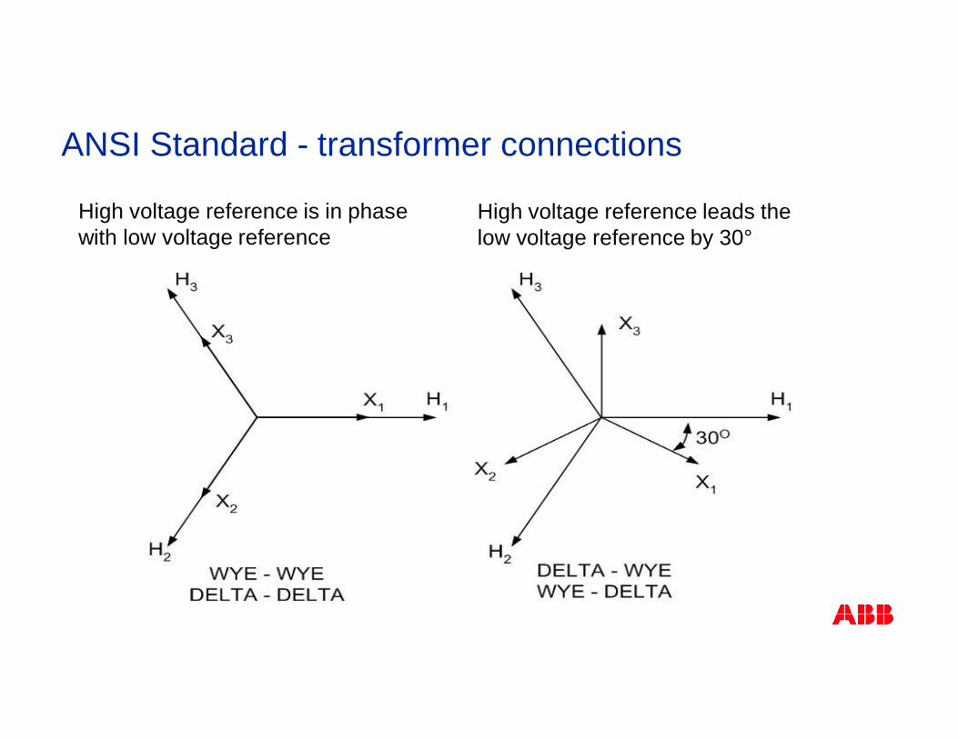
High voltage reference leads thelow voltage reference by 30°
High voltage reference is in phasewith low voltage reference
ANSI Standard - transformer connections
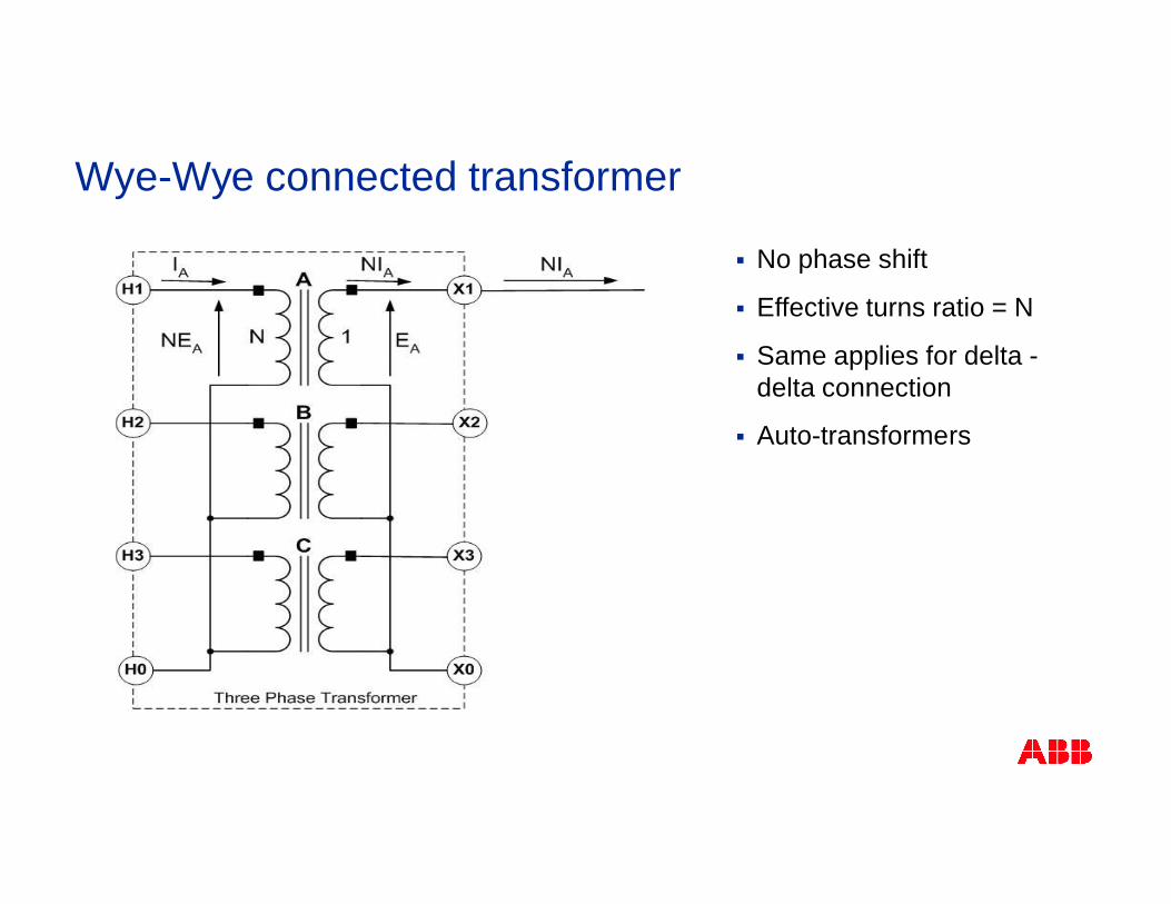
Wye-Wye connected transformer
§ No phase shift
§ Effective turns ratio = N
§ Same applies for delta -delta connection
§ Auto-transformers
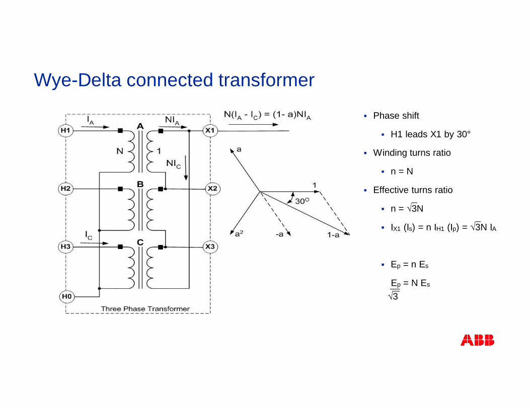
Wye-Delta connected transformer
§ Phase shift
§ H1 leads X1 by 30°
§ Winding turns ratio
§ n = N
§ Effective turns ratio
§ n = √3N
§ IX1 (Is) = n IH1 (Ip) = √3N IA
§ Ep = n Es
Ep = N Es
√3
= N √3 IA = N IA
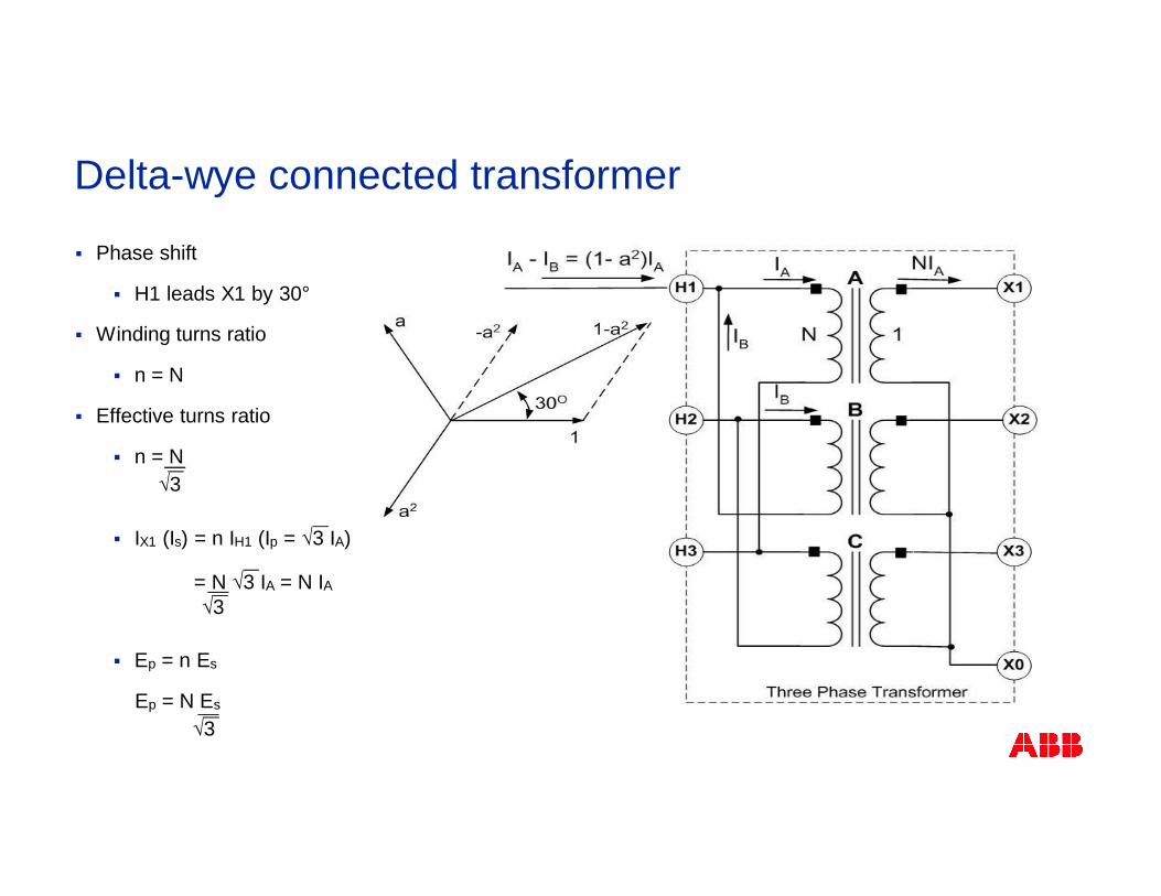
§ Phase shift
§ H1 leads X1 by 30°
§ Winding turns ratio
§ n = N
§ Effective turns ratio
§ n = N
§ IX1 (Is) = n IH1 (Ip = √3 IA)
§ Ep = n Es
Ep = N Es
Delta-wye connected transformer
√3
√3
√3
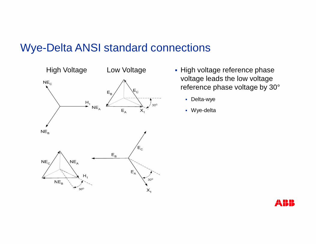
High Voltage Low Voltage § High voltage reference phasevoltage leads the low voltagereference phase voltage by 30°§ Delta-wye
§ Wye-delta
Wye-Delta ANSI standard connections
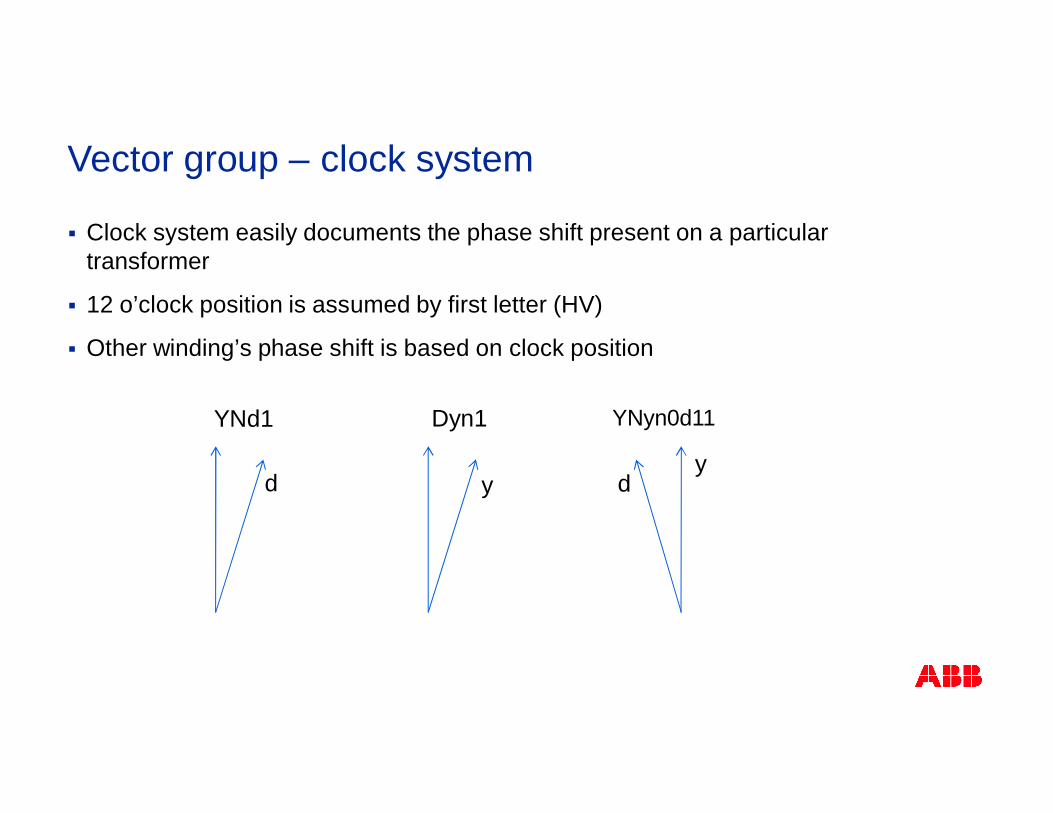
Vector group – clock system
§ Clock system easily documents the phase shift present on a particulartransformer
§ 12 o’clock position is assumed by first letter (HV)
§ Other winding’s phase shift is based on clock position
YNd1
d
Dyn1
y
YNyn0d11
dy
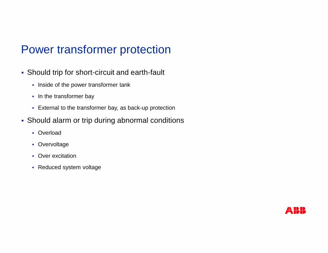
Power transformer protection
§ Should trip for short-circuit and earth-fault§ Inside of the power transformer tank
§ In the transformer bay
§ External to the transformer bay, as back-up protection
§ Should alarm or trip during abnormal conditions§ Overload
§ Overvoltage
§ Over excitation
§ Reduced system voltage
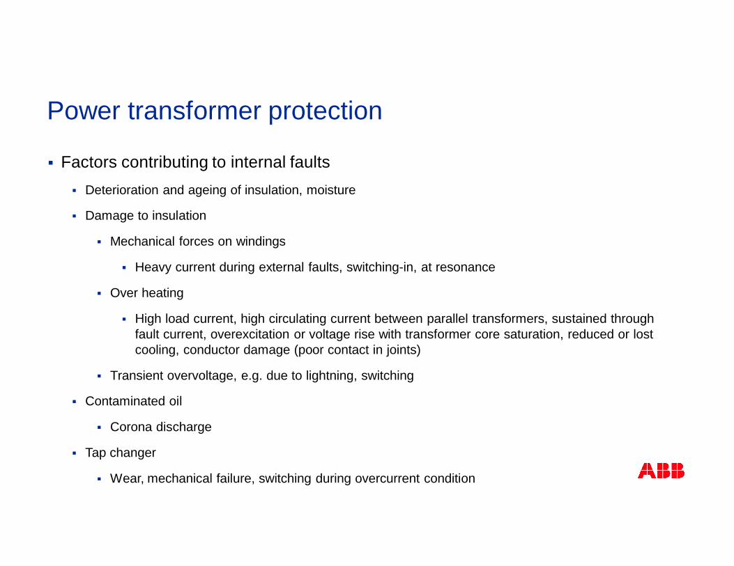
Power transformer protection
§ Factors contributing to internal faults§ Deterioration and ageing of insulation, moisture
§ Damage to insulation
§ Mechanical forces on windings
§ Heavy current during external faults, switching-in, at resonance
§ Over heating
§ High load current, high circulating current between parallel transformers, sustained throughfault current, overexcitation or voltage rise with transformer core saturation, reduced or lostcooling, conductor damage (poor contact in joints)
§ Transient overvoltage, e.g. due to lightning, switching
§ Contaminated oil
§ Corona discharge
§ Tap changer
§ Wear, mechanical failure, switching during overcurrent condition
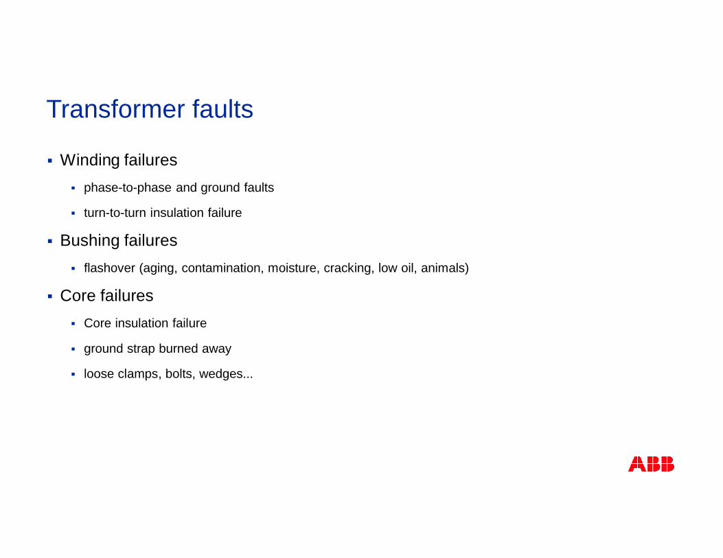
Transformer faults
§ Winding failures§ phase-to-phase and ground faults
§ turn-to-turn insulation failure
§ Bushing failures§ flashover (aging, contamination, moisture, cracking, low oil, animals)
§ Core failures§ Core insulation failure
§ ground strap burned away
§ loose clamps, bolts, wedges...
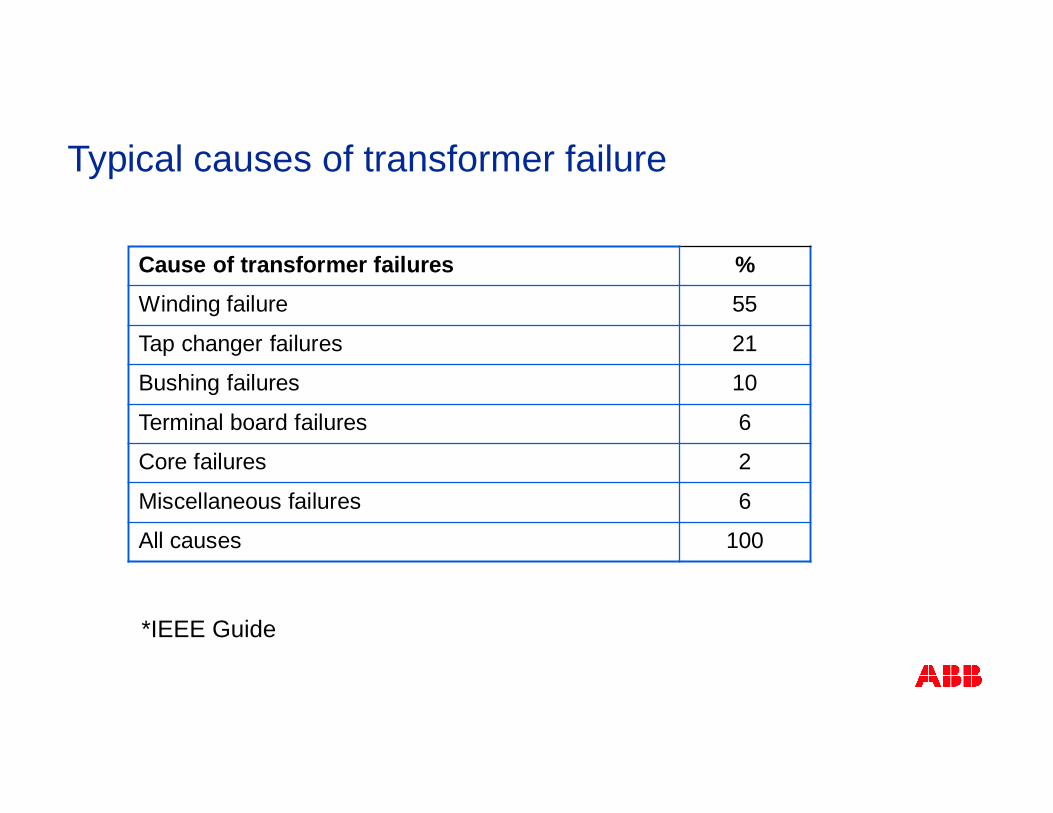
Typical causes of transformer failure
Cause of transformer failures %Winding failure 55
Tap changer failures 21
Bushing failures 10
Terminal board failures 6
Core failures 2
Miscellaneous failures 6
All causes 100
*IEEE Guide
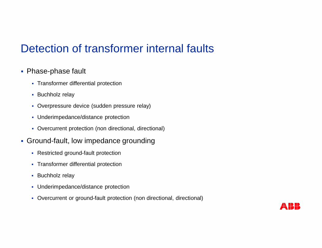
Detection of transformer internal faults
§ Phase-phase fault§ Transformer differential protection
§ Buchholz relay
§ Overpressure device (sudden pressure relay)
§ Underimpedance/distance protection
§ Overcurrent protection (non directional, directional)
§ Ground-fault, low impedance grounding§ Restricted ground-fault protection
§ Transformer differential protection
§ Buchholz relay
§ Underimpedance/distance protection
§ Overcurrent or ground-fault protection (non directional, directional)
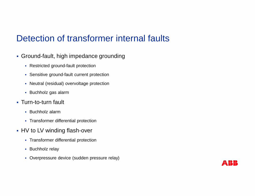
Detection of transformer internal faults
§ Ground-fault, high impedance grounding§ Restricted ground-fault protection
§ Sensitive ground-fault current protection
§ Neutral (residual) overvoltage protection
§ Buchholz gas alarm
§ Turn-to-turn fault§ Buchholz alarm
§ Transformer differential protection
§ HV to LV winding flash-over§ Transformer differential protection
§ Buchholz relay
§ Overpressure device (sudden pressure relay)
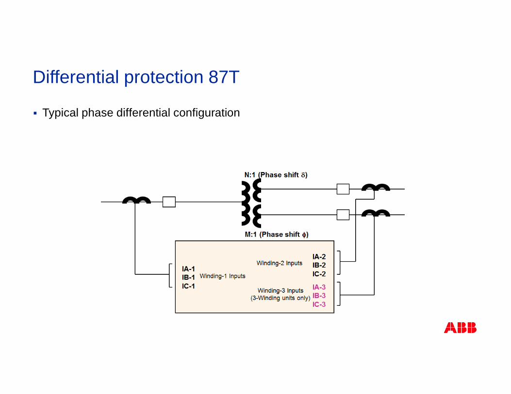
Differential protection 87T
§ Typical phase differential configuration
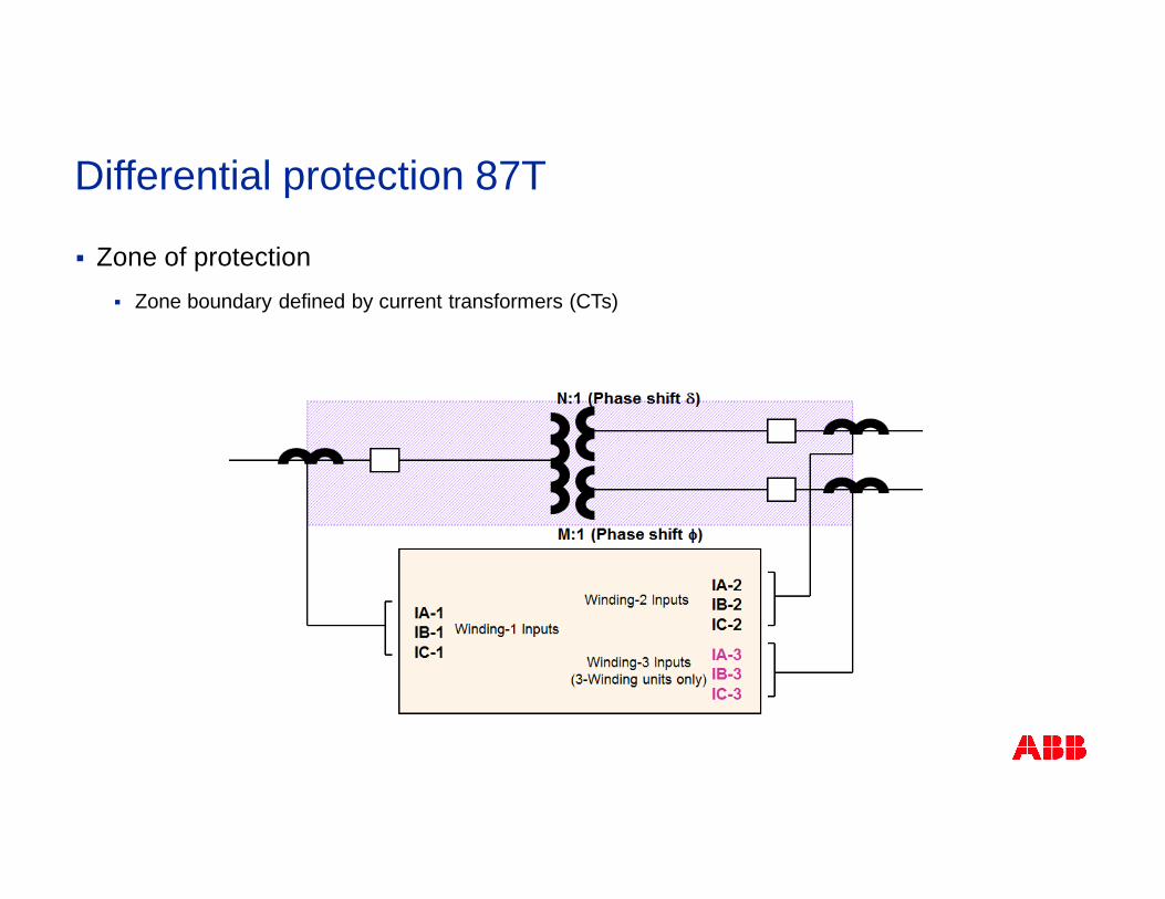
Differential protection 87T
§ Zone of protection§ Zone boundary defined by current transformers (CTs)
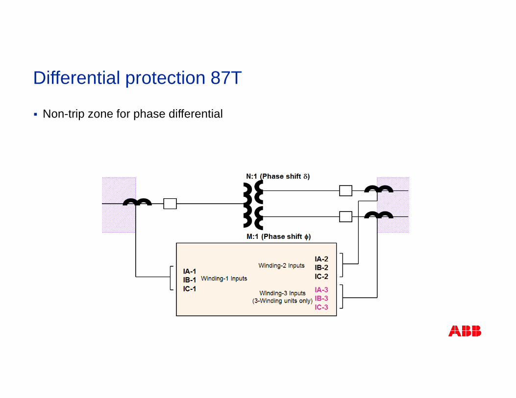
Differential protection 87T
§ Non-trip zone for phase differential
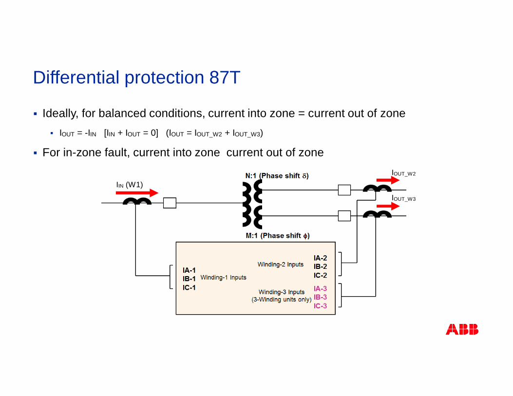
Differential protection 87T
§ Ideally, for balanced conditions, current into zone = current out of zone§ IOUT = -IIN [IIN + IOUT = 0] (IOUT = IOUT_W2 + IOUT_W3)
§ For in-zone fault, current into zone current out of zone
IIN (W1)IOUT_W2
IOUT_W3
I_W1
I_W3
I_W2
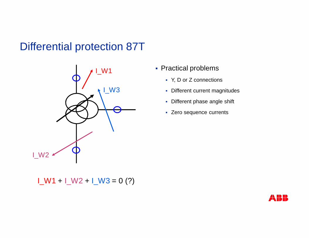
I_W1 + I_W2 + I_W3 = 0 (?)
§ Practical problems§ Y, D or Z connections
§ Different current magnitudes
§ Different phase angle shift
§ Zero sequence currents
Differential protection 87T
§ Unbalance currents due to factors other than faults§ Currents that flow on only one side of the power transformer
§ Magnetizing currents that flow on only the power source side
§ Normal magnetizing currents
§ Inrush magnetizing currents
§ Overexcitation magnetizing currents
§ Currents that cannot be transformed to the other windings
§ Zero sequence currents
§ Error in the power transformer turns ratio due to OLTC
§ Inequality of the instrument current transformers
§ Different ratings of current transformers
§ Different types of current transformers
Differential protection 87T
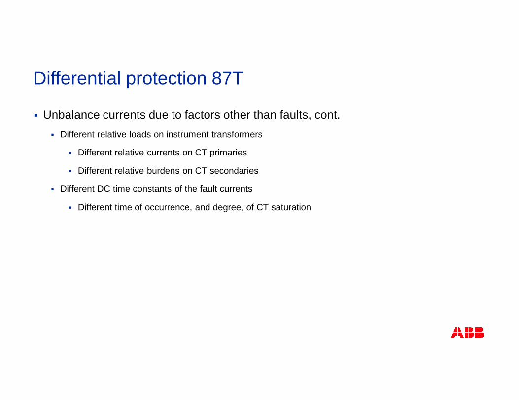
§ Unbalance currents due to factors other than faults, cont.§ Different relative loads on instrument transformers
§ Different relative currents on CT primaries
§ Different relative burdens on CT secondaries
§ Different DC time constants of the fault currents
§ Different time of occurrence, and degree, of CT saturation
Differential protection 87T
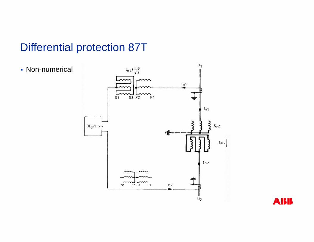
§ Non-numerical
Differential protection 87T
§ Typically, all CTs are directly star-connected to the IED
§ The conversion of all current contributions is performed mathematically§ Magnitude conversion of all current contributions to the magnitude reference side (normally the
HV-side (W1-side))
§ Phase angle conversion of all current contributions to the phase reference side (using pre-programmed matrices). ABB: Phase reference is the first star-connected winding (W1®W2®W3), otherwise if no star winding, first delta-connected winding (W1 ® W2 ®W3)
§ The power transformer connection type, the vector group and the subtraction of zero sequencecurrents (On/Off) are setting parameters – from these the differential protection calculates off-line the matrix coefficients, which are then used in the on-line calculations
§ If the subtraction of the zero sequence currents from the current contribution from any winding isrequired (set On), a matrix with different coefficients will be used (does both the phase angleconversion and zero sequence current subtraction)
Numerical differential protection 87T
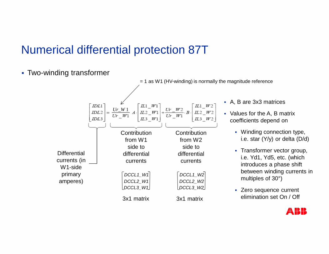
§ Two-winding transformer
Differentialcurrents (in
W1-sideprimary
amperes)
Contributionfrom W1side to
differentialcurrents
Contributionfrom W2side to
differentialcurrents
DCCL2_W1DCCL3_W1
DCCL1_W1DCCL2_W2DCCL3_W2
DCCL1_W2
Ur_W 1
= 1 as W1 (HV-winding) is normally the magnitude reference
§ A, B are 3x3 matrices
§ Values for the A, B matrixcoefficients depend on
§ Winding connection type,i.e. star (Y/y) or delta (D/d)
§ Transformer vector group,i.e. Yd1, Yd5, etc. (whichintroduces a phase shiftbetween winding currents inmultiples of 30°)
§ Zero sequence currentelimination set On / Off3x1 matrix 3x1 matrix
Numerical differential protection 87T
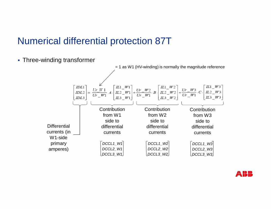
§ Three-winding transformer
Differentialcurrents (in
W1-sideprimary
amperes)
Contributionfrom W1side to
differentialcurrents
Contributionfrom W2side to
differentialcurrents
DCCL2_W1DCCL3_W1
DCCL1_W1DCCL2_W2DCCL3_W2
DCCL1_W2
Ur_W 1
Contributionfrom W3side to
differentialcurrents
DCCL2_W3DCCL3_W3
DCCL1_W3
= 1 as W1 (HV-winding) is normally the magnitude reference
Numerical differential protection 87T
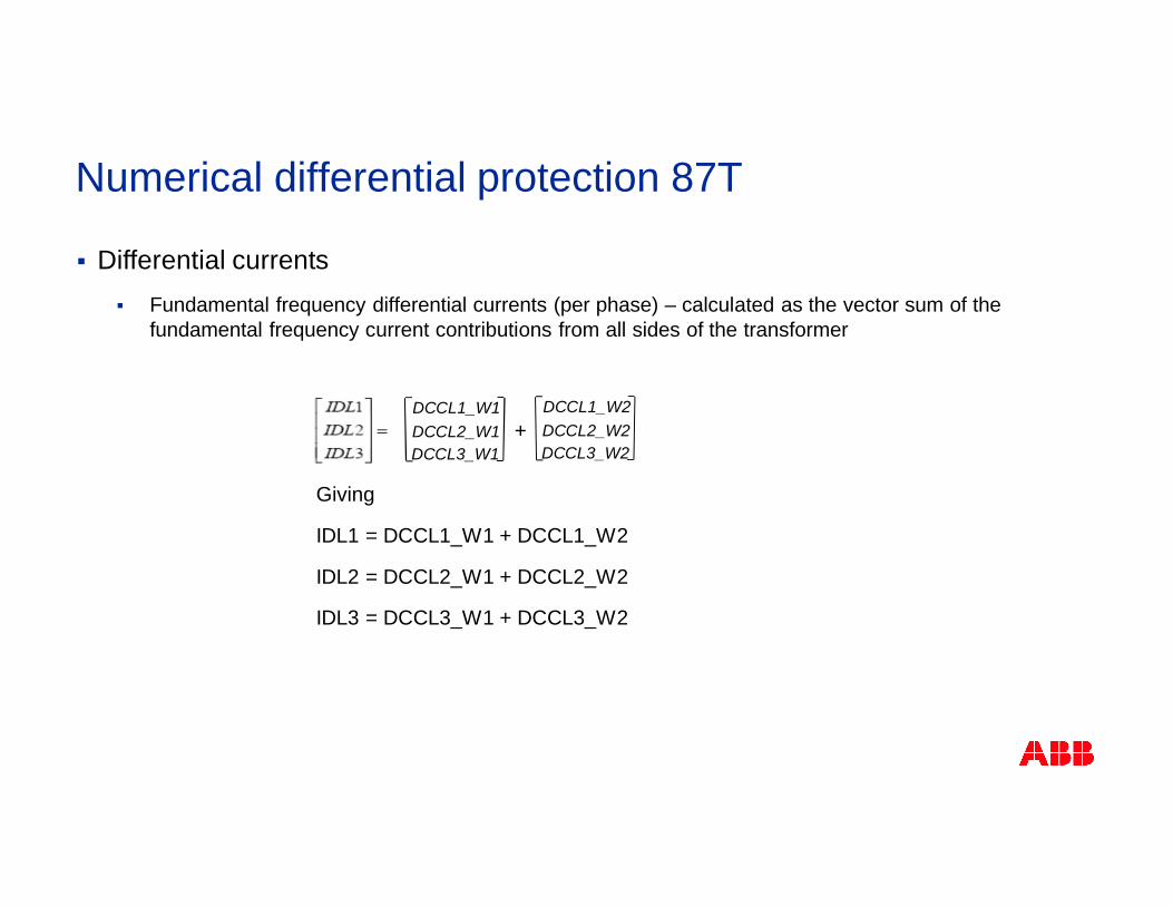
§ Differential currents§ Fundamental frequency differential currents (per phase) – calculated as the vector sum of the
fundamental frequency current contributions from all sides of the transformer
Giving
IDL1 = DCCL1_W1 + DCCL1_W2
IDL2 = DCCL2_W1 + DCCL2_W2
IDL3 = DCCL3_W1 + DCCL3_W2
DCCL2_W1DCCL3_W1
DCCL1_W1DCCL2_W2DCCL3_W2
DCCL1_W2+
Numerical differential protection 87T
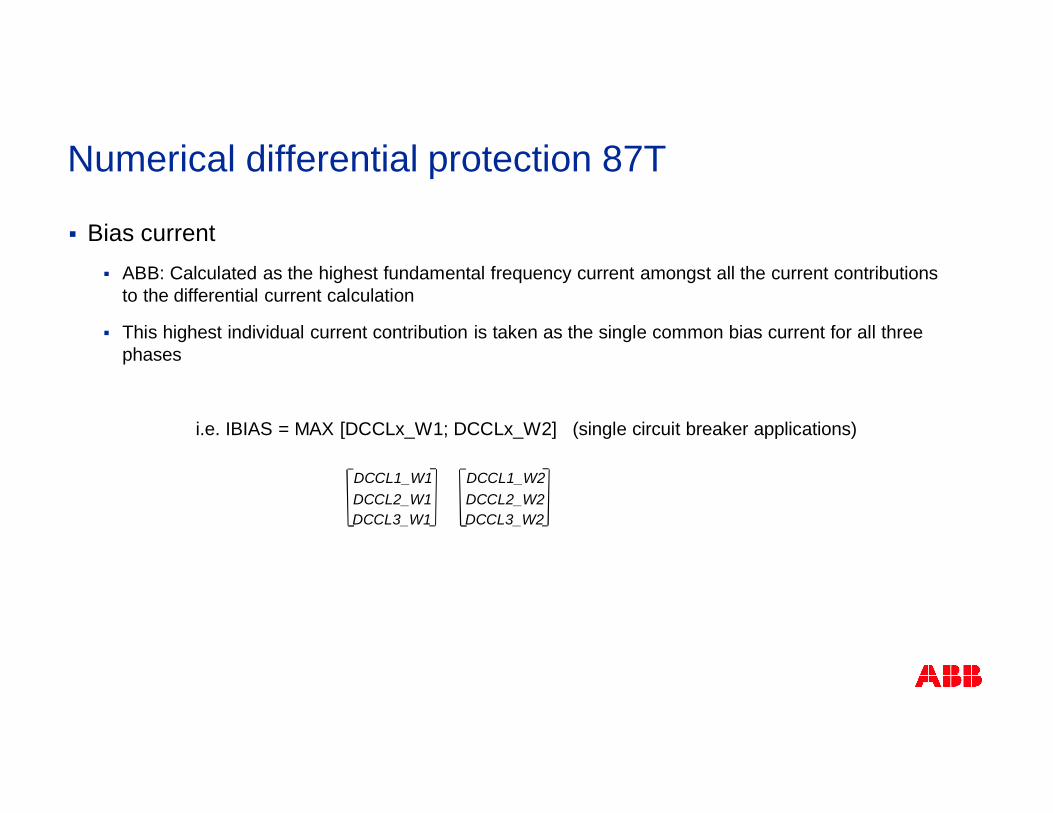
§ Bias current§ ABB: Calculated as the highest fundamental frequency current amongst all the current contributions
to the differential current calculation
§ This highest individual current contribution is taken as the single common bias current for all threephases
i.e. IBIAS = MAX [DCCLx_W1; DCCLx_W2] (single circuit breaker applications)
Numerical differential protection 87T
DCCL2_W2DCCL3_W2
DCCL1_W2DCCL2_W1DCCL3_W1
DCCL1_W1
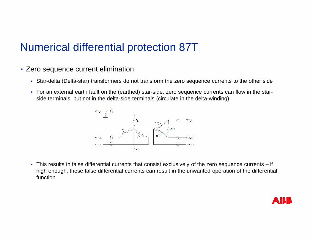
§ Zero sequence current elimination§ Star-delta (Delta-star) transformers do not transform the zero sequence currents to the other side
§ For an external earth fault on the (earthed) star-side, zero sequence currents can flow in the star-side terminals, but not in the delta-side terminals (circulate in the delta-winding)
§ This results in false differential currents that consist exclusively of the zero sequence currents – ifhigh enough, these false differential currents can result in the unwanted operation of the differentialfunction
Numerical differential protection 87T
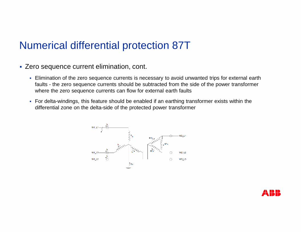
§ Zero sequence current elimination, cont.§ Elimination of the zero sequence currents is necessary to avoid unwanted trips for external earth
faults - the zero sequence currents should be subtracted from the side of the power transformerwhere the zero sequence currents can flow for external earth faults
§ For delta-windings, this feature should be enabled if an earthing transformer exists within thedifferential zone on the delta-side of the protected power transformer
Numerical differential protection 87T
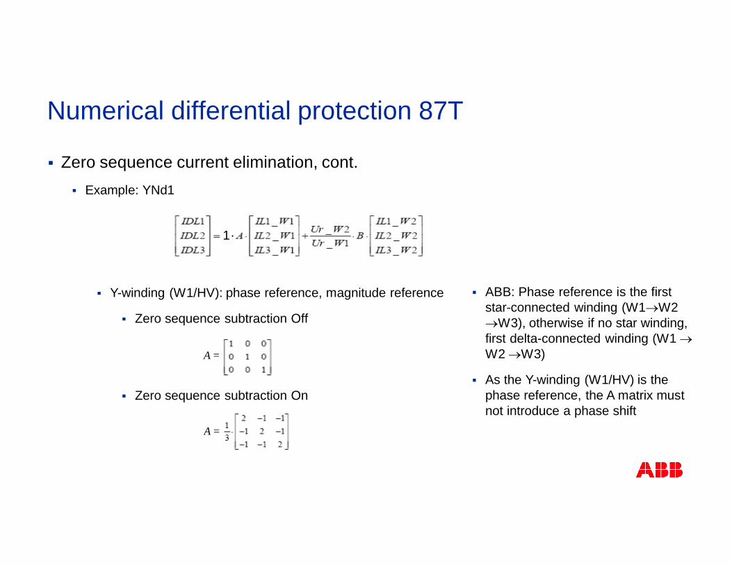
§ Zero sequence current elimination, cont.§ Example: YNd1
§ Y-winding (W1/HV): phase reference, magnitude reference
§ Zero sequence subtraction Off
§ Zero sequence subtraction On
A =
1.
A =
§ ABB: Phase reference is the firststar-connected winding (W1®W2®W3), otherwise if no star winding,first delta-connected winding (W1 ®W2 ®W3)
§ As the Y-winding (W1/HV) is thephase reference, the A matrix mustnot introduce a phase shift
Numerical differential protection 87T
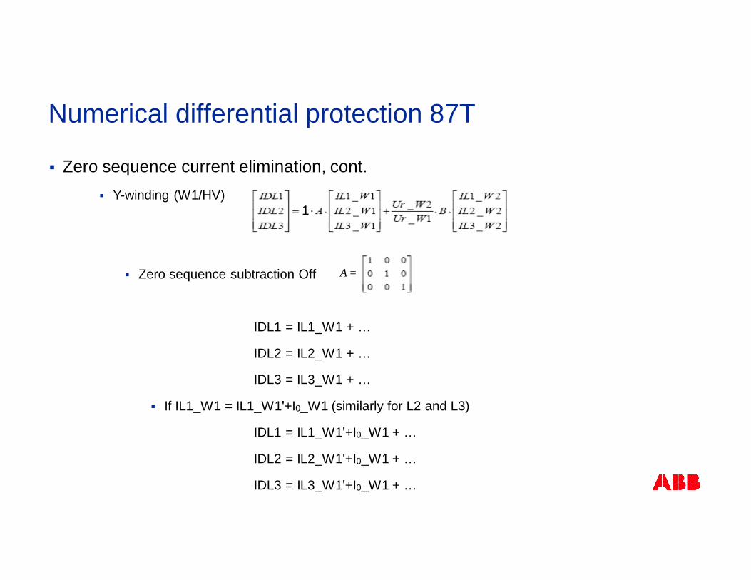
§ Zero sequence current elimination, cont.§ Y-winding (W1/HV)
§ Zero sequence subtraction Off
IDL1 = IL1_W1 + …
IDL2 = IL2_W1 + …
IDL3 = IL3_W1 + …
§ If IL1_W1 = IL1_W1ʹ+I0_W1 (similarly for L2 and L3)
IDL1 = IL1_W1ʹ+I0_W1 + …
IDL2 = IL2_W1ʹ+I0_W1 + …
IDL3 = IL3_W1ʹ+I0_W1 + …
A =
1.
Numerical differential protection 87T
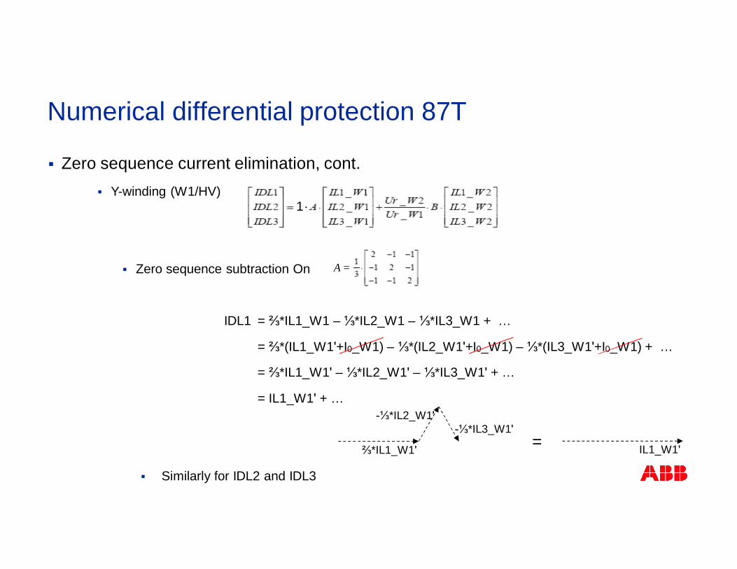
§ Zero sequence current elimination, cont.§ Y-winding (W1/HV)
§ Zero sequence subtraction On
IDL1 = ⅔*IL1_W1 – ⅓*IL2_W1 – ⅓*IL3_W1 + …
= ⅔*(IL1_W1ʹ+I0_W1) – ⅓*(IL2_W1ʹ+I0_W1) – ⅓*(IL3_W1ʹ+I0_W1) + …
= ⅔*IL1_W1ʹ – ⅓*IL2_W1ʹ – ⅓*IL3_W1ʹ + …
= IL1_W1ʹ + …
§ Similarly for IDL2 and IDL3
⅔*IL1_W1ʹ
-⅓*IL2_W1ʹ-⅓*IL3_W1ʹ
IL1_W1ʹ=
Numerical differential protection 87T
1.
A =
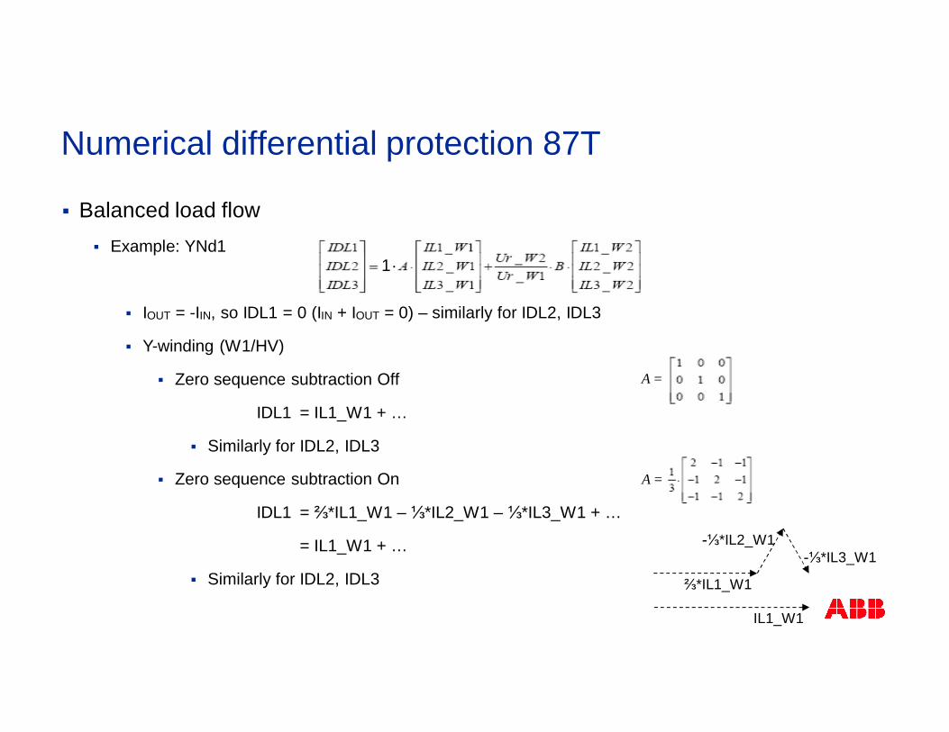
§ Balanced load flow§ Example: YNd1
§ IOUT = -IIN, so IDL1 = 0 (IIN + IOUT = 0) – similarly for IDL2, IDL3
§ Y-winding (W1/HV)
§ Zero sequence subtraction Off
IDL1 = IL1_W1 + …
§ Similarly for IDL2, IDL3
§ Zero sequence subtraction On
IDL1 = ⅔*IL1_W1 – ⅓*IL2_W1 – ⅓*IL3_W1 + …
= IL1_W1 + …
§ Similarly for IDL2, IDL3
A =
A =
Numerical differential protection 87T
1.
⅔*IL1_W1
-⅓*IL2_W1-⅓*IL3_W1
IL1_W1
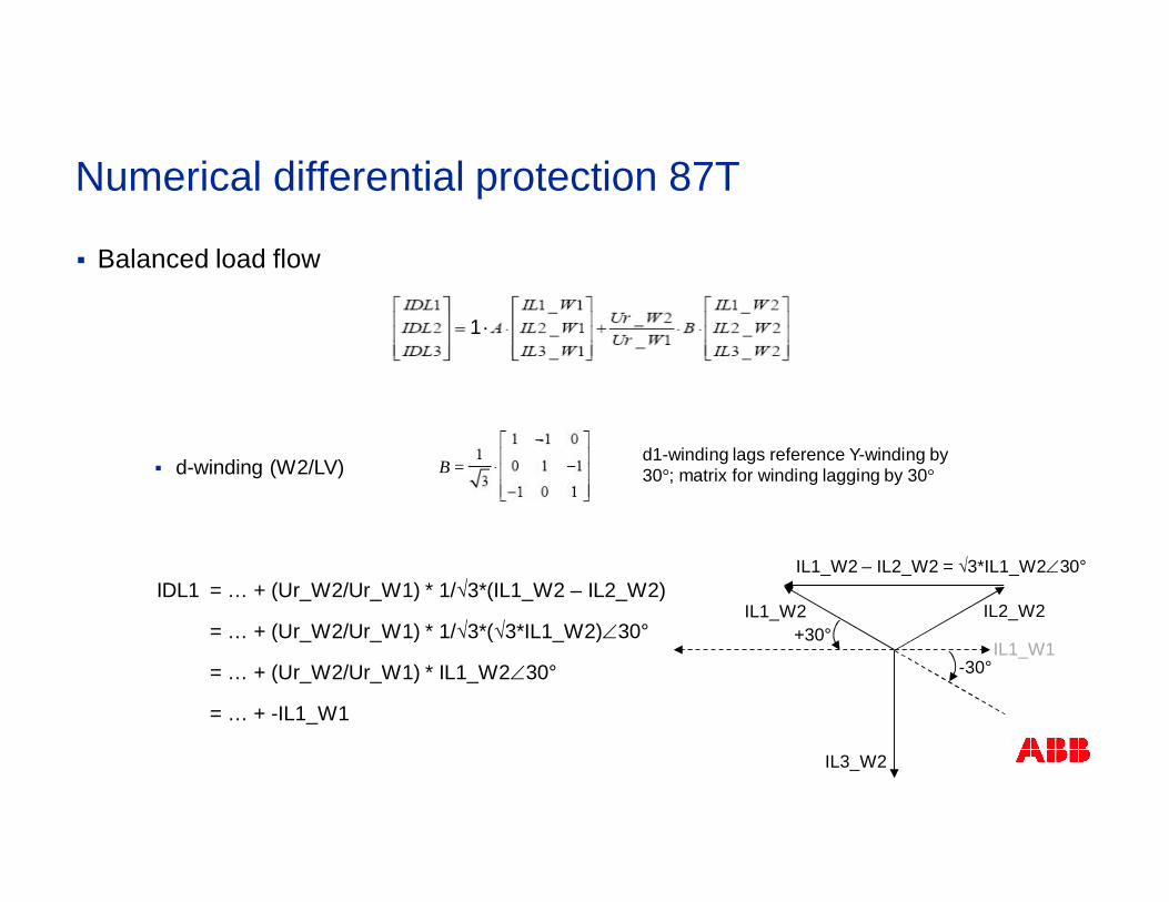
§ Balanced load flow
§ d-winding (W2/LV)
IDL1 = … + (Ur_W2/Ur_W1) * 1/√3*(IL1_W2 – IL2_W2)
= … + (Ur_W2/Ur_W1) * 1/√3*(√3*IL1_W2)Ð30°
= … + (Ur_W2/Ur_W1) * IL1_W2Ð30°
= … + -IL1_W1
B =
IL1_W2 IL2_W2
IL3_W2
IL1_W1
IL1_W2 – IL2_W2 = √3*IL1_W2Ð30°
-30°
+30°
d1-winding lags reference Y-winding by30°; matrix for winding lagging by 30°
Numerical differential protection 87T
1.
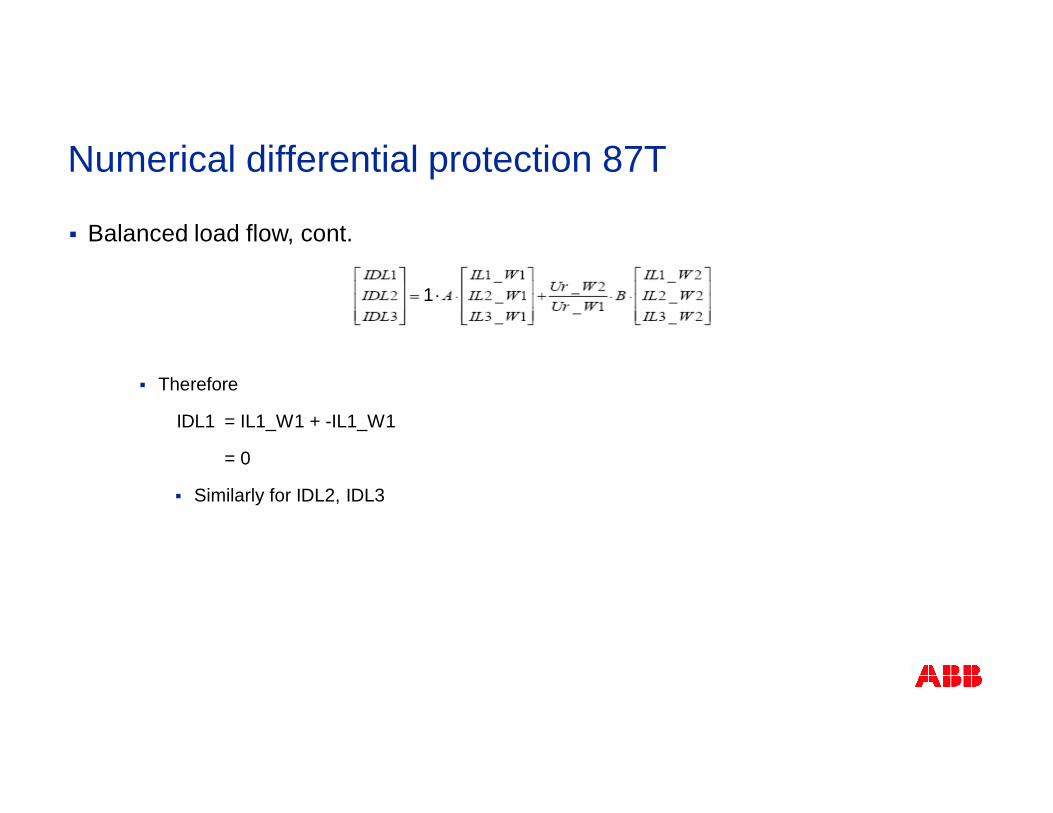
§ Balanced load flow, cont.
§ Therefore
IDL1 = IL1_W1 + -IL1_W1
= 0
§ Similarly for IDL2, IDL3
Numerical differential protection 87T
1.
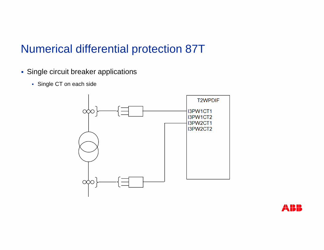
§ Single circuit breaker applications§ Single CT on each side
Numerical differential protection 87T
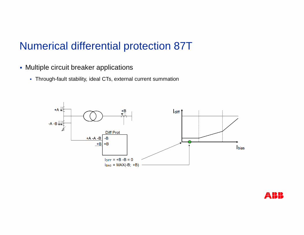
§ Multiple circuit breaker applications§ Through-fault stability, ideal CTs, external current summation
Numerical differential protection 87T
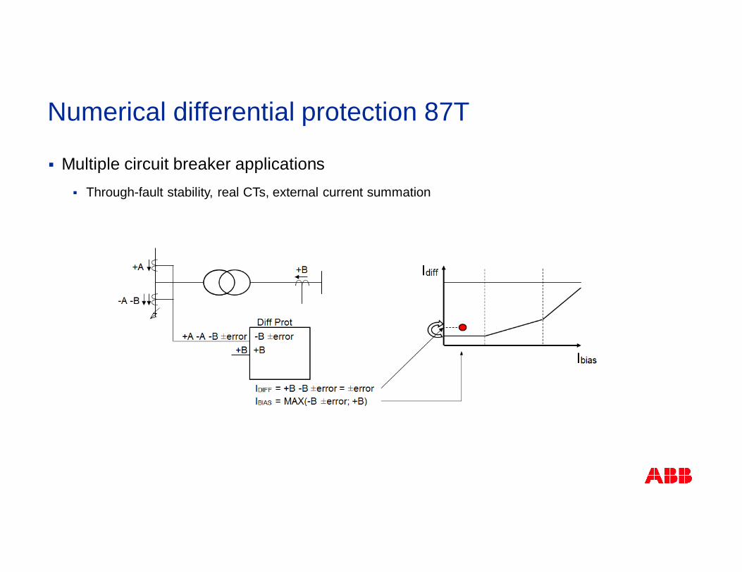
§ Multiple circuit breaker applications§ Through-fault stability, real CTs, external current summation
Numerical differential protection 87T
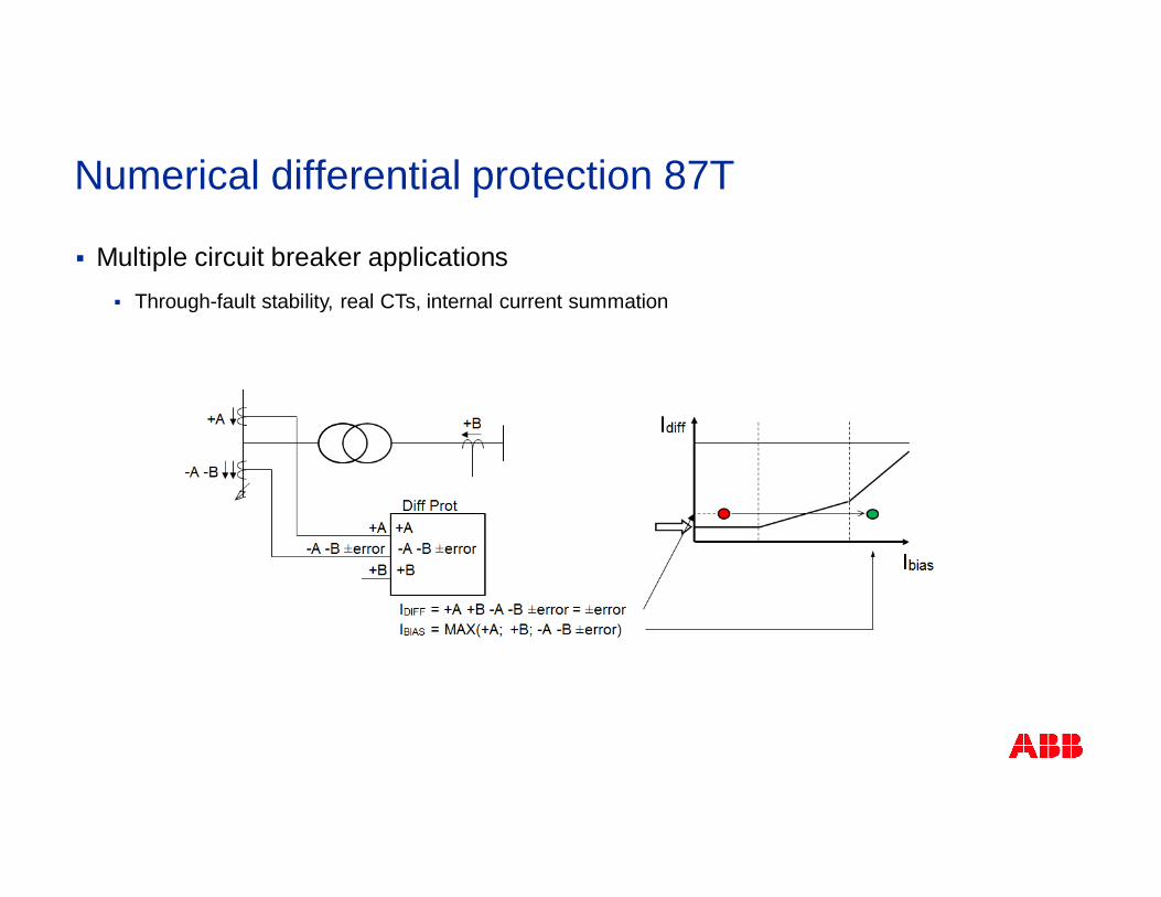
§ Multiple circuit breaker applications§ Through-fault stability, real CTs, internal current summation
Numerical differential protection 87T
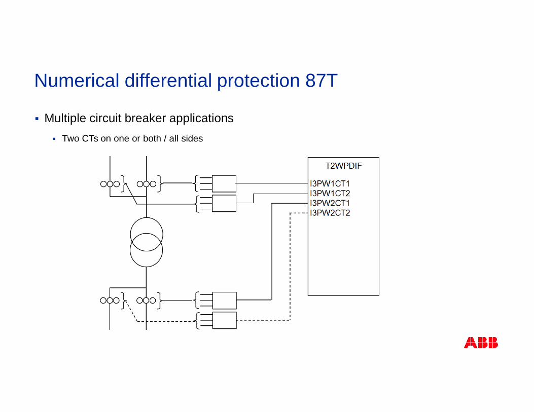
§ Multiple circuit breaker applications§ Two CTs on one or both / all sides
Numerical differential protection 87T
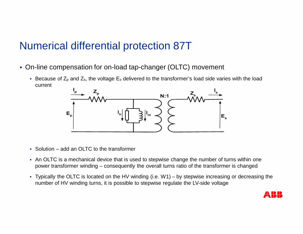
§ On-line compensation for on-load tap-changer (OLTC) movement§ Because of Zp and Zs, the voltage Es delivered to the transformer’s load side varies with the load
current
§ Solution – add an OLTC to the transformer
§ An OLTC is a mechanical device that is used to stepwise change the number of turns within onepower transformer winding – consequently the overall turns ratio of the transformer is changed
§ Typically the OLTC is located on the HV winding (i.e. W1) – by stepwise increasing or decreasing thenumber of HV winding turns, it is possible to stepwise regulate the LV-side voltage
Numerical differential protection 87T
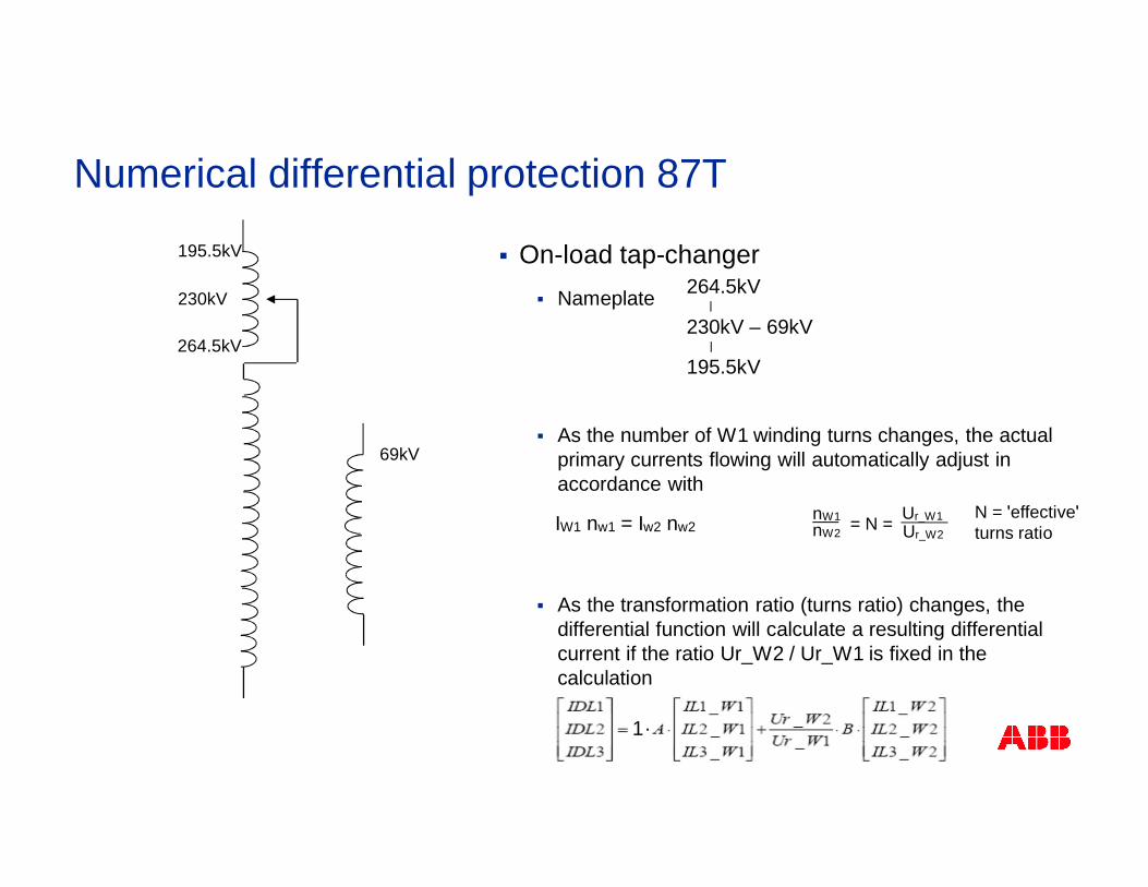
§ On-load tap-changer§ Nameplate
§ As the number of W1 winding turns changes, the actualprimary currents flowing will automatically adjust inaccordance with
§ As the transformation ratio (turns ratio) changes, thedifferential function will calculate a resulting differentialcurrent if the ratio Ur_W2 / Ur_W1 is fixed in thecalculation
Ur_W1Ur_W2nW2
nW1
230kV
195.5kV
264.5kV
69kV
264.5kV
230kV – 69kV
195.5kV
Numerical differential protection 87T
IW1 nw1 = Iw2 nw2 = N =N = ʹeffectiveʹturns ratio
1.
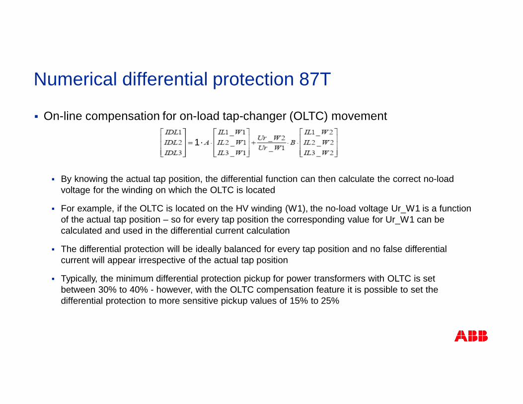
§ On-line compensation for on-load tap-changer (OLTC) movement
§ By knowing the actual tap position, the differential function can then calculate the correct no-loadvoltage for the winding on which the OLTC is located
§ For example, if the OLTC is located on the HV winding (W1), the no-load voltage Ur_W1 is a functionof the actual tap position – so for every tap position the corresponding value for Ur_W1 can becalculated and used in the differential current calculation
§ The differential protection will be ideally balanced for every tap position and no false differentialcurrent will appear irrespective of the actual tap position
§ Typically, the minimum differential protection pickup for power transformers with OLTC is setbetween 30% to 40% - however, with the OLTC compensation feature it is possible to set thedifferential protection to more sensitive pickup values of 15% to 25%
1.
Numerical differential protection 87T
%100×DD
=RES
DIFF
IIm
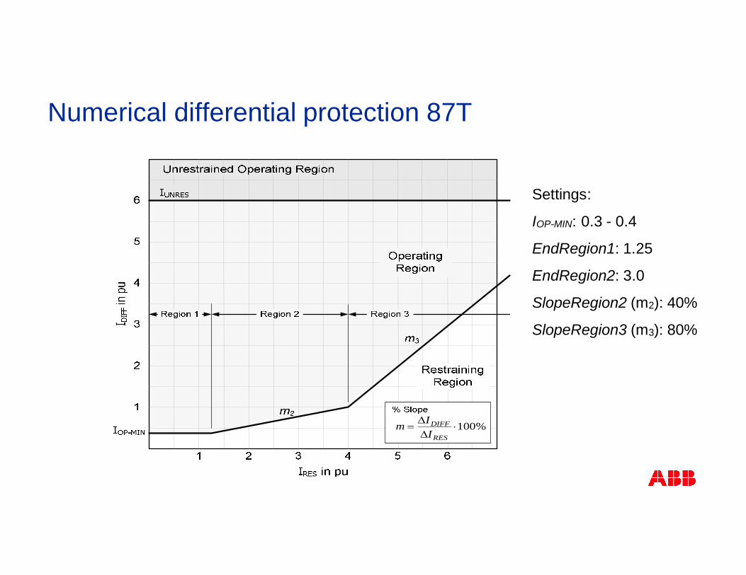
Settings:
IOP-MIN: 0.3 - 0.4
EndRegion1: 1.25
EndRegion2: 3.0
SlopeRegion2 (m2): 40%
SlopeRegion3 (m3): 80%
Numerical differential protection 87T

§ Restrained (i.e. stabilized) characteristic§ Region 1
§ Most sensitive part
§ Characteristic a straight line
§ Current flow normal load current
§ Typical reason for existence of false differential currents in this section is non compensation fortap position
§ Region 2
§ First slope (low percentage)
§ Caters for false differential currents when higher than normal currents flow through the currenttransformers
%100×DD
=RES
DIFF
IIm
Numerical differential protection 87T

§ Restrained (i.e. stabilized) characteristic§ Region 3
§ Second slope (higher percentage)
§ Provides higher tolerance to substantial current transformer saturation for high through faultcurrents, which can be expected in this section
%100×DD
=RES
DIFF
IIm
Numerical differential protection 87T
§ Blocking criteria (phase segregated)§ Have the power to block a trip – prevents unwanted tripping due to CT saturation, magnetizing inrush
currents, or due to magnetizing currents caused by overvoltages
§ Magnetizing currents (inrush / overvoltage) flow only on one side of a power transformer, and aretherefore always a cause of false differential currents
Numerical differential protection 87T
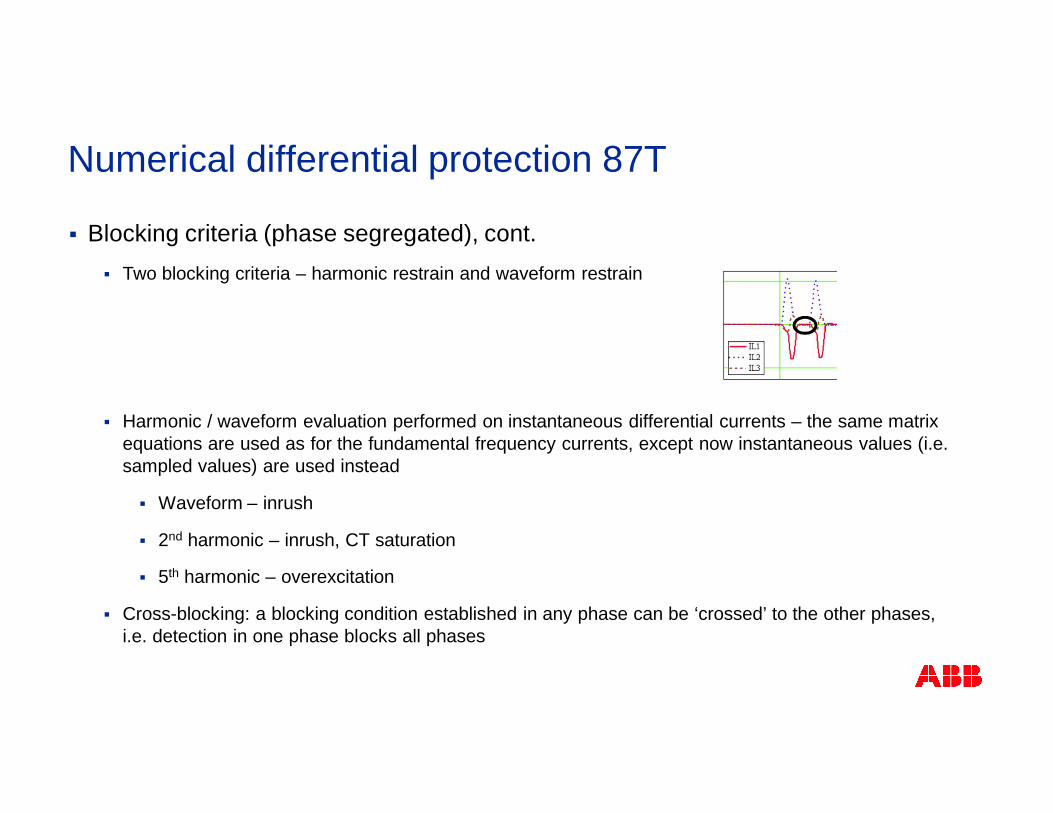
§ Blocking criteria (phase segregated), cont.§ Two blocking criteria – harmonic restrain and waveform restrain
§ Harmonic / waveform evaluation performed on instantaneous differential currents – the same matrixequations are used as for the fundamental frequency currents, except now instantaneous values (i.e.sampled values) are used instead
§ Waveform – inrush
§ 2nd harmonic – inrush, CT saturation
§ 5th harmonic – overexcitation
§ Cross-blocking: a blocking condition established in any phase can be ‘crossed’ to the other phases,i.e. detection in one phase blocks all phases
Numerical differential protection 87T
§ Factors that affect the inrush current
§ The size of the transformer
§ The peak value of the magnetizing inrush current is generally higher for smaller transformers
§ Duration of the inrush current is longer for the larger transformers
§ The location of energized winding (inner, outer)
§ Low Voltage winding that is wound closer to the magnetic core has less impedance than theouter winding – consequently energizing the transformer from the LV winding will cause moreinrush than energizing from the HV winding
§ Typical values:
§ LV side: magnitude (peak) of inrush current may be 10-20 times the rated current
§ HV side: magnitude (peak) of inrush current may be 5-10 times the rated current
§ The connection of the windings
Numerical differential protection 87T
§ Factors that affect the inrush current, cont.
§ The point of wave when the switch closes – switching instant
§ The maximum inrush current will happen when the transformer is switched at voltage zero
§ Statistical data indicates every 5th or 6th transformer energization will result in high values ofinrush
§ The magnetic properties of the core
§ Amount / direction of remanent (residual) flux in the core
§ The higher the remanent flux, the higher the inrush
§ Worst case: switching-in occurs at voltage zero, with the direction of the remanent flux suchthat the flux increases from the remanent flux level
§ The source impedance and transformer air-core reactance
§ EG. lower source impedance results in the higher inrush
Numerical differential protection 87T
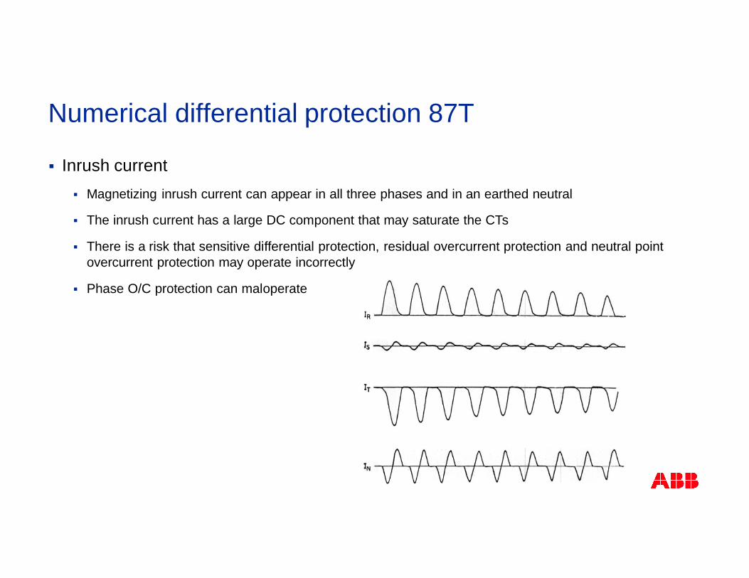
§ Inrush current§ Magnetizing inrush current can appear in all three phases and in an earthed neutral
§ The inrush current has a large DC component that may saturate the CTs
§ There is a risk that sensitive differential protection, residual overcurrent protection and neutral pointovercurrent protection may operate incorrectly
§ Phase O/C protection can maloperate
Numerical differential protection 87T
§ Inrush current§ Differential protection commonly uses 2nd harmonic value to distinguish between inrush current
and short circuit current – 2nd harmonic > threshold used to block differential operation
§ Normal operation / internal short circuits have only small 2nd harmonic in current
§ Inrush current has significant 2nd harmonic
§ 2nd harmonic in currents small during overvoltages
Numerical differential protection 87T
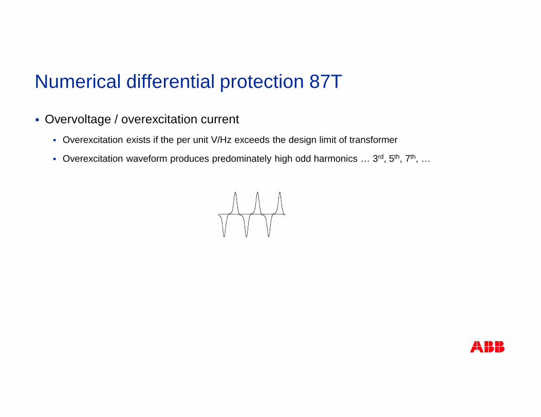
§ Overvoltage / overexcitation current§ Overexcitation exists if the per unit V/Hz exceeds the design limit of transformer
§ Overexcitation waveform produces predominately high odd harmonics … 3rd, 5th, 7th, …
Numerical differential protection 87T
§ Overvoltage / overexcitation current, cont.§ Differential protection commonly uses 5th harmonic value to distinguish overexcitation current –
5th harmonic > threshold used to block differential operation
§ 3rd harmonic not used as it is a prevalent quantity on the power system produced from manysources
§ Separate V/Hz function normally used to provide tripping for overexcitation
Numerical differential protection 87T
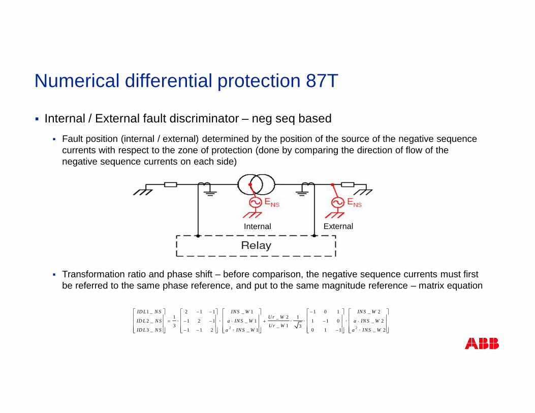
§ Internal / External fault discriminator – neg seq based§ Fault position (internal / external) determined by the position of the source of the negative sequence
currents with respect to the zone of protection (done by comparing the direction of flow of thenegative sequence currents on each side)
§ Transformation ratio and phase shift – before comparison, the negative sequence currents must firstbe referred to the same phase reference, and put to the same magnitude reference – matrix equation
2 2
1 _ 2 1 1 _ 1 1 0 1 _ 21 _ 2 1
2 _ 1 2 1 _ 1 1 1 0 _ 23 _ 1 3
3 _ 1 1 2 _ 1 0 1 1 _ 2
ID L N S IN S W IN S WU r W
ID L N S a IN S W a IN S WUr W
ID L N S a IN S W a INS W
- - -
= - - × + - ×
- - -
é ù é ù é ù é ù é ùê ú ê ú ê ú ê ú ê ú× × × × ×ê ú ê ú ê ú ê ú ê ú
× ×ê ú ê ú ê ú ê ú ê úë û ë û ë û ë û ë û
Internal External
Numerical differential protection 87T
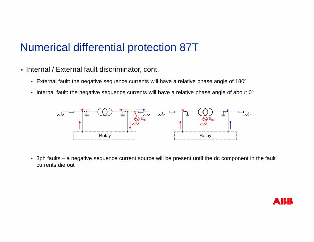
§ Internal / External fault discriminator, cont.§ External fault: the negative sequence currents will have a relative phase angle of 180°
§ Internal fault: the negative sequence currents will have a relative phase angle of about 0°
§ 3ph faults – a negative sequence current source will be present until the dc component in the faultcurrents die out
Numerical differential protection 87T
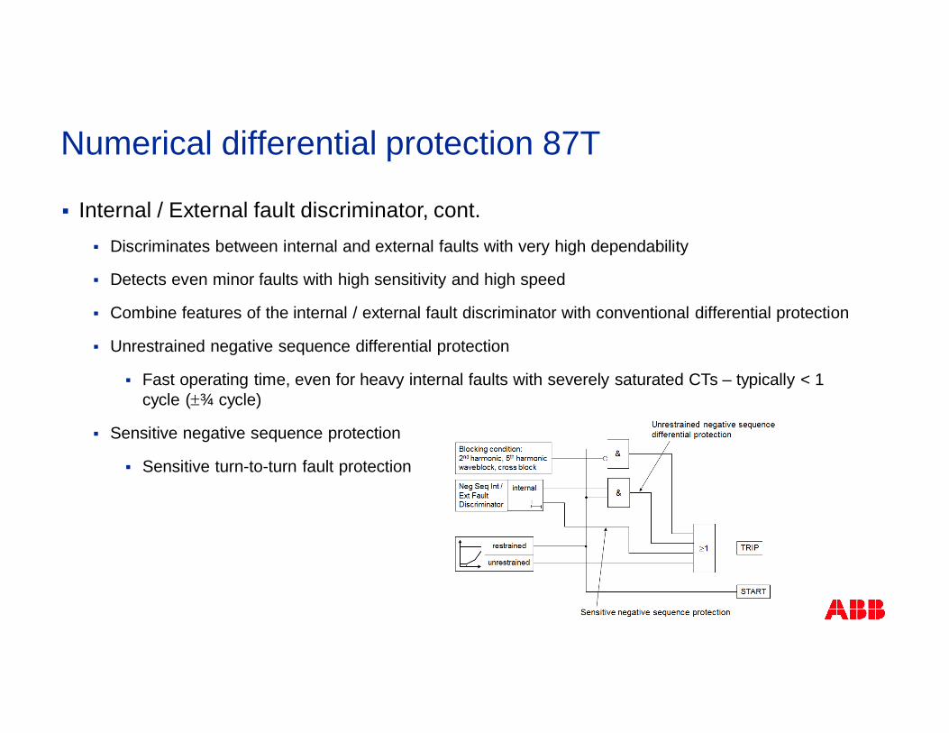
§ Internal / External fault discriminator, cont.§ Discriminates between internal and external faults with very high dependability
§ Detects even minor faults with high sensitivity and high speed
§ Combine features of the internal / external fault discriminator with conventional differential protection
§ Unrestrained negative sequence differential protection
§ Fast operating time, even for heavy internal faults with severely saturated CTs – typically < 1cycle (±¾ cycle)
§ Sensitive negative sequence protection
§ Sensitive turn-to-turn fault protection
Numerical differential protection 87T
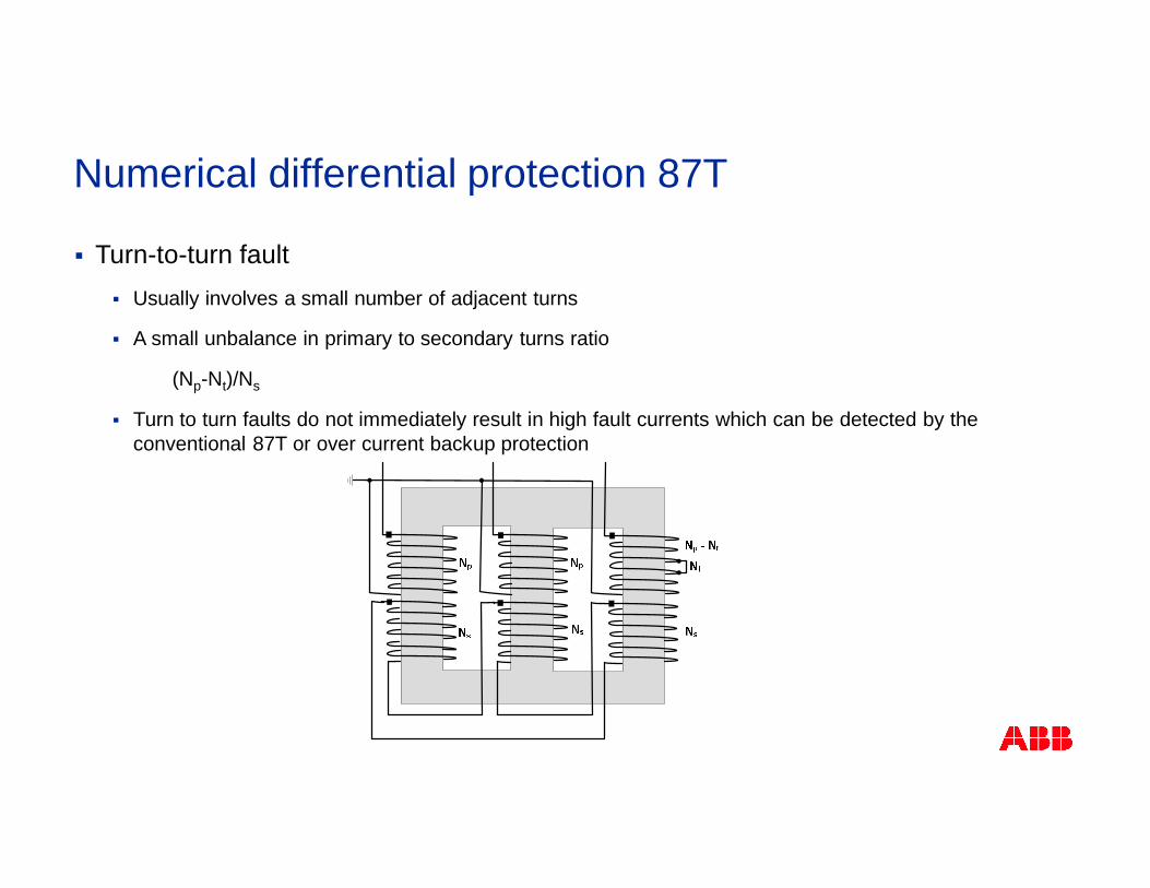
§ Turn-to-turn fault§ Usually involves a small number of adjacent turns
§ A small unbalance in primary to secondary turns ratio
(Np-Nt)/Ns
§ Turn to turn faults do not immediately result in high fault currents which can be detected by theconventional 87T or over current backup protection
Numerical differential protection 87T
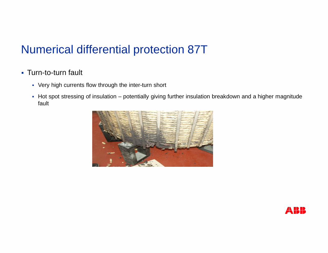
§ Turn-to-turn fault§ Very high currents flow through the inter-turn short
§ Hot spot stressing of insulation – potentially giving further insulation breakdown and a higher magnitudefault
Numerical differential protection 87T
§ Turn-to-turn fault
§ Sudden Pressure Relay (SPR)
§ Slow
§ Negative sequence differential
§ Turn to turn faults result in a source of negative sequence current due to asymmetry in the numberof turns across the phases of the faulted winding
§ Turn to turn faults can be detected based on the direction of flow of the negative sequence currents
Numerical differential protection 87T
§ Other features
§ Open CT detection§ To prevent a maloperation of the transformer differential function if a loaded main CT connected to
the differential protection is by mistake open-circuited on the secondary side
§ For an interruption in one phase, the current in that phase will suddenly drop to zero, while thecurrents in the other two phases will continue as before
§ An open CT must be detected quickly (within 10ms), to ensure in-time blocking of the differentialfunction
Numerical differential protection 87T
§ Other features, cont.
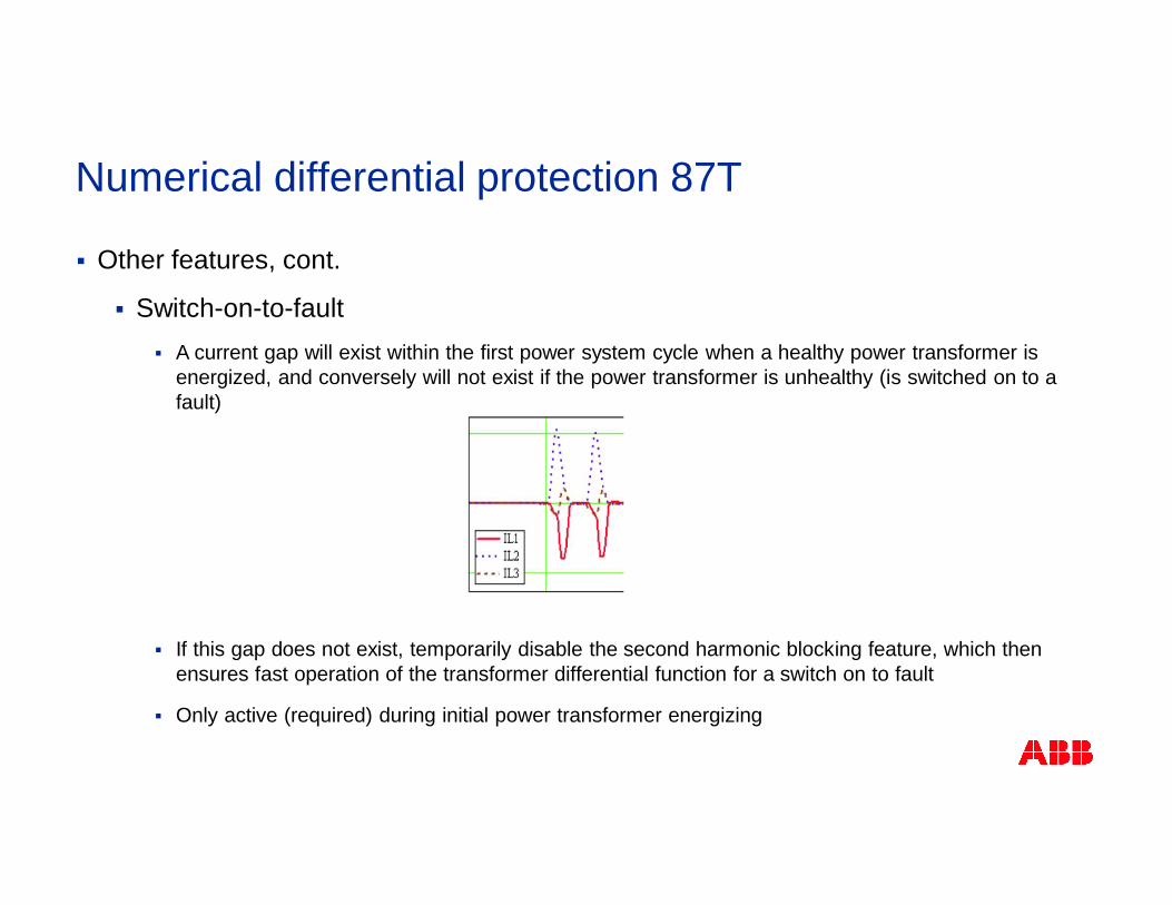
§ Switch-on-to-fault§ A current gap will exist within the first power system cycle when a healthy power transformer is
energized, and conversely will not exist if the power transformer is unhealthy (is switched on to afault)
§ If this gap does not exist, temporarily disable the second harmonic blocking feature, which thenensures fast operation of the transformer differential function for a switch on to fault
§ Only active (required) during initial power transformer energizing
Numerical differential protection 87T
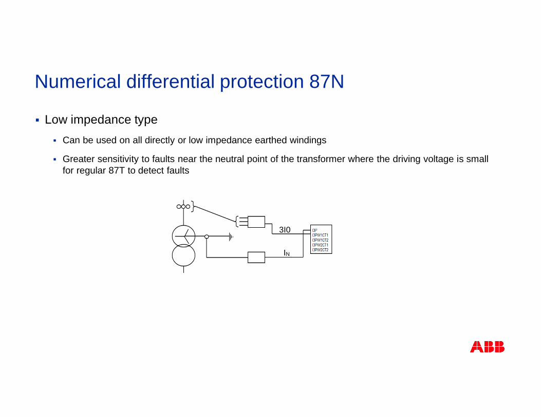
§ Low impedance type§ Can be used on all directly or low impedance earthed windings
§ Greater sensitivity to faults near the neutral point of the transformer where the driving voltage is smallfor regular 87T to detect faults
3I0
IN
Numerical differential protection 87N
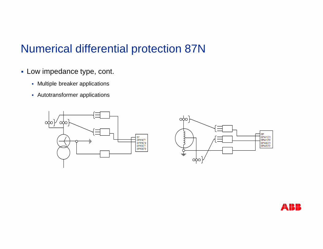
§ Low impedance type, cont.§ Multiple breaker applications
§ Autotransformer applications
Numerical differential protection 87N
§ Low impedance type, cont.§ Zero sequence differential
§ Differential current
§ Vector sum of the fundamental frequency neutral current and the fundamental frequencyresidual current (calculated from the three line-side fundamental frequency phase currents)
§ Bias current
§ ABB: Calculated as the highest fundamental frequency current amongst all the currentcontributions to the differential current calculation
IBIAS = MAX [Wx_L1; Wx_L2; Wx_L3; IN] (single circuit breaker applications)
IDIFF = IN + 3I0
Numerical differential protection 87N
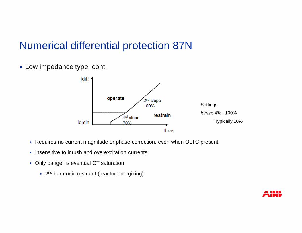
§ Low impedance type, cont.
§ Requires no current magnitude or phase correction, even when OLTC present
§ Insensitive to inrush and overexcitation currents
§ Only danger is eventual CT saturation
§ 2nd harmonic restraint (reactor energizing)
Settings
Idmin: 4% - 100%
Typically 10%
Numerical differential protection 87N
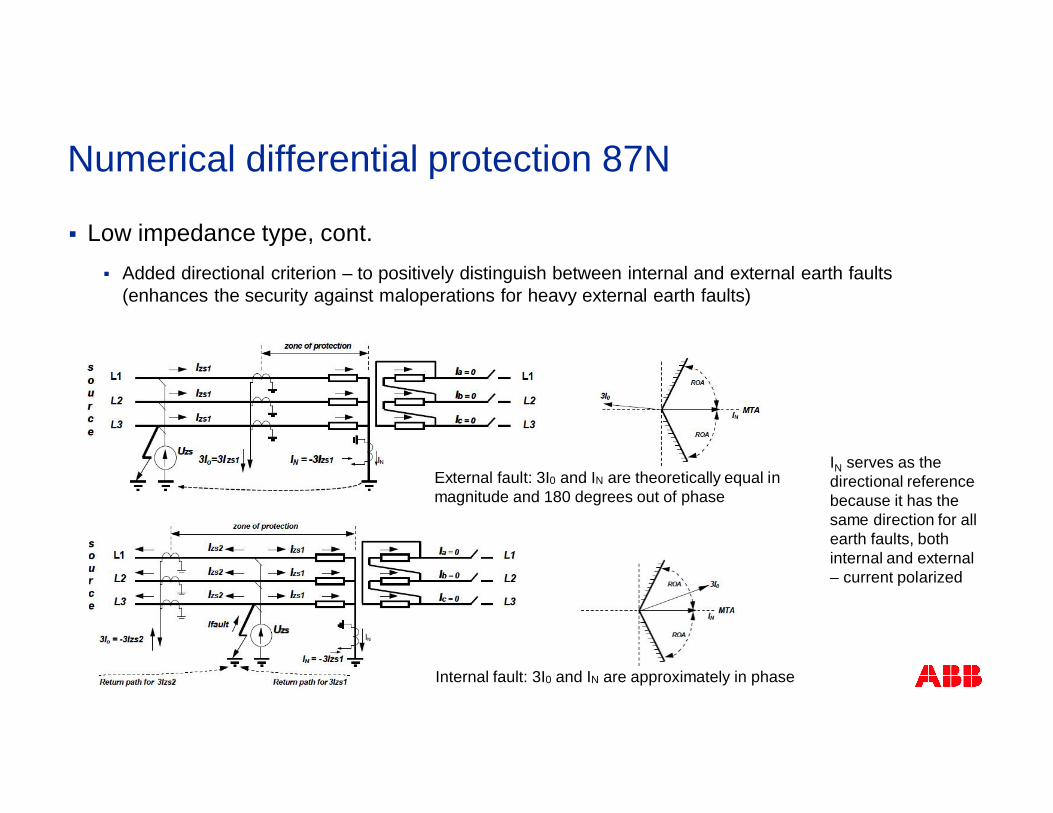
§ Low impedance type, cont.§ Added directional criterion – to positively distinguish between internal and external earth faults
(enhances the security against maloperations for heavy external earth faults)
IN serves as thedirectional referencebecause it has thesame direction for allearth faults, bothinternal and external– current polarized
External fault: 3I0 and IN are theoretically equal inmagnitude and 180 degrees out of phase
Internal fault: 3I0 and IN are approximately in phase
Numerical differential protection 87N
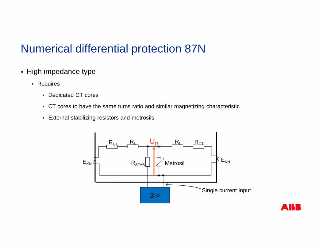
§ High impedance type§ Requires
§ Dedicated CT cores
§ CT cores to have the same turns ratio and similar magnetizing characteristic
§ External stabilizing resistors and metrosils
RCT RCTRLRL
EKNEKN RSTAB Metrosil
UR
3I>Single current input
Numerical differential protection 87N
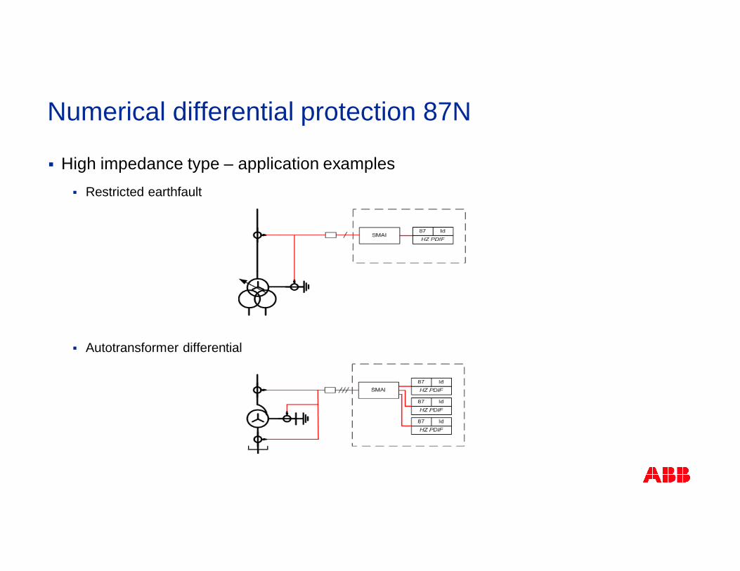
§ High impedance type – application examples§ Restricted earthfault
§ Autotransformer differential
Numerical differential protection 87N
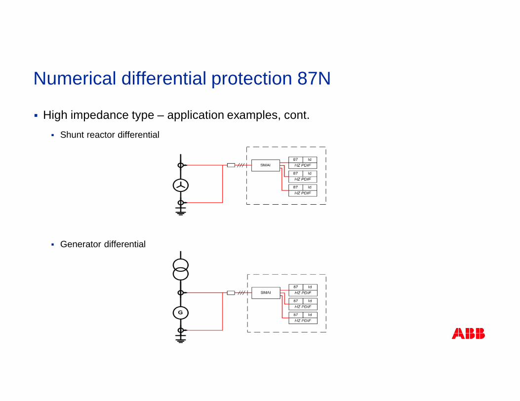
§ High impedance type – application examples, cont.§ Shunt reactor differential
§ Generator differential
Numerical differential protection 87N
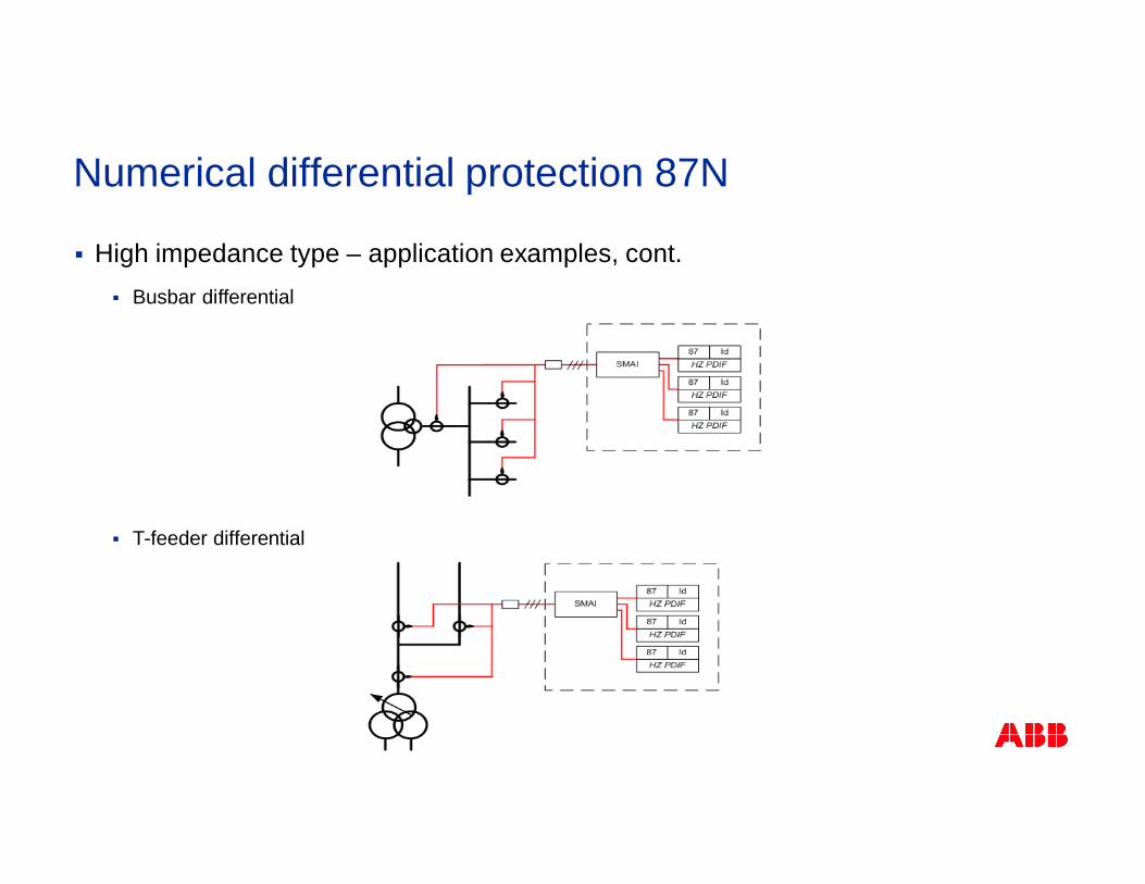
§ High impedance type – application examples, cont.§ Busbar differential
§ T-feeder differential
Numerical differential protection 87N
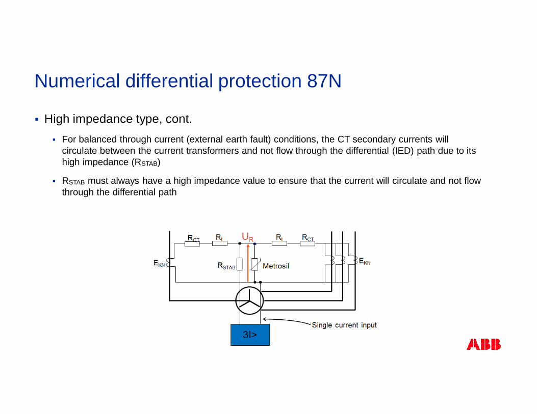
§ High impedance type, cont.§ For balanced through current (external earth fault) conditions, the CT secondary currents will
circulate between the current transformers and not flow through the differential (IED) path due to itshigh impedance (RSTAB)
§ RSTAB must always have a high impedance value to ensure that the current will circulate and not flowthrough the differential path
Numerical differential protection 87N
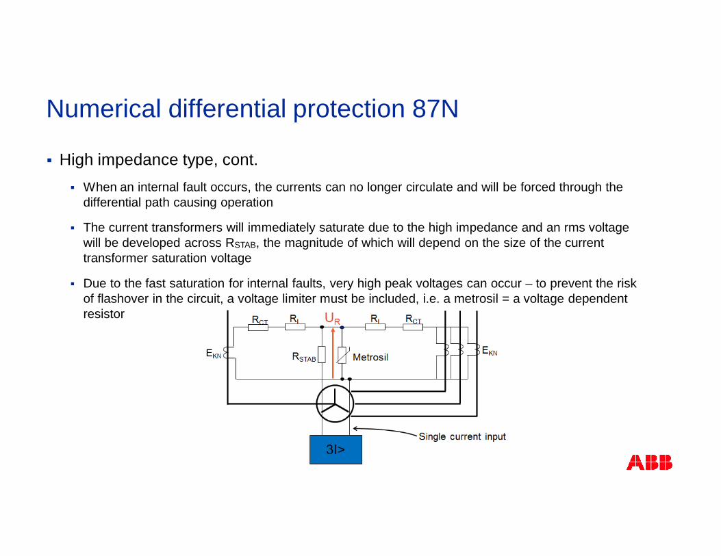
§ High impedance type, cont.§ When an internal fault occurs, the currents can no longer circulate and will be forced through the
differential path causing operation
§ The current transformers will immediately saturate due to the high impedance and an rms voltagewill be developed across RSTAB, the magnitude of which will depend on the size of the currenttransformer saturation voltage
§ Due to the fast saturation for internal faults, very high peak voltages can occur – to prevent the riskof flashover in the circuit, a voltage limiter must be included, i.e. a metrosil = a voltage dependentresistor
Numerical differential protection 87N
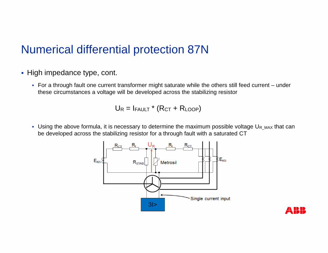
§ High impedance type, cont.§ For a through fault one current transformer might saturate while the others still feed current – under
these circumstances a voltage will be developed across the stabilizing resistor
§ Using the above formula, it is necessary to determine the maximum possible voltage UR_MAX that canbe developed across the stabilizing resistor for a through fault with a saturated CT
UR = IFAULT * (RCT + RLOOP)
Numerical differential protection 87N
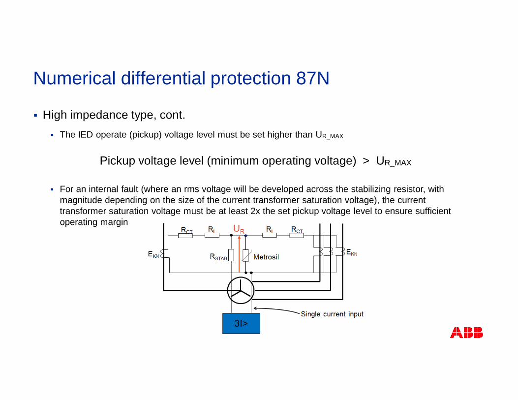
§ High impedance type, cont.§ The IED operate (pickup) voltage level must be set higher than UR_MAX
§ For an internal fault (where an rms voltage will be developed across the stabilizing resistor, withmagnitude depending on the size of the current transformer saturation voltage), the currenttransformer saturation voltage must be at least 2x the set pickup voltage level to ensure sufficientoperating margin
Pickup voltage level (minimum operating voltage) > UR_MAX
Numerical differential protection 87N
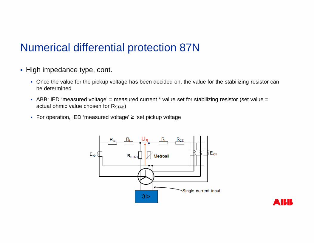
§ High impedance type, cont.§ Once the value for the pickup voltage has been decided on, the value for the stabilizing resistor can
be determined
§ ABB: IED ‘measured voltage’ = measured current * value set for stabilizing resistor (set value =actual ohmic value chosen for RSTAB)
§ For operation, IED ‘measured voltage’ ≥ set pickup voltage
Numerical differential protection 87N
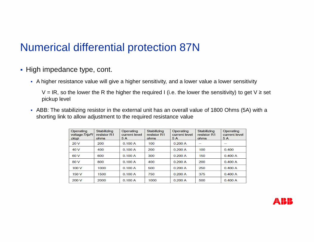
§ High impedance type, cont.§ A higher resistance value will give a higher sensitivity, and a lower value a lower sensitivity
V = IR, so the lower the R the higher the required I (i.e. the lower the sensitivity) to get V ≥ setpickup level
§ ABB: The stabilizing resistor in the external unit has an overall value of 1800 Ohms (5A) with ashorting link to allow adjustment to the required resistance value
Numerical differential protection 87N
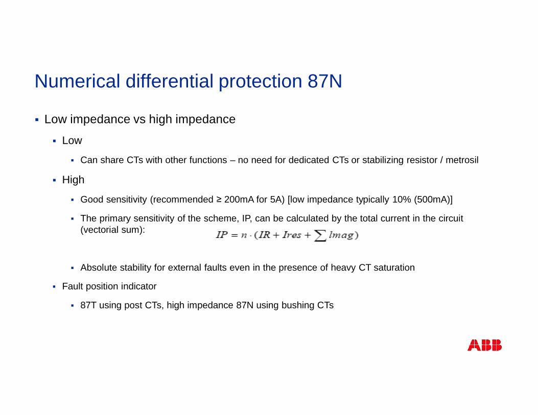
§ Low impedance vs high impedance
§ Low
§ Can share CTs with other functions – no need for dedicated CTs or stabilizing resistor / metrosil
§ High
§ Good sensitivity (recommended ≥ 200mA for 5A) [low impedance typically 10% (500mA)]
§ The primary sensitivity of the scheme, IP, can be calculated by the total current in the circuit(vectorial sum):
§ Absolute stability for external faults even in the presence of heavy CT saturation
§ Fault position indicator
§ 87T using post CTs, high impedance 87N using bushing CTs
Numerical differential protection 87N
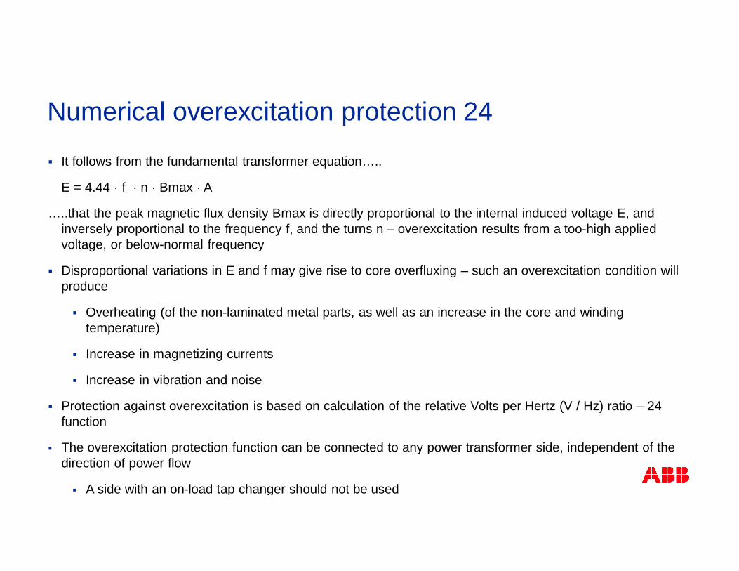
§ It follows from the fundamental transformer equation…..
E = 4.44 · f · n · Bmax · A
…..that the peak magnetic flux density Bmax is directly proportional to the internal induced voltage E, andinversely proportional to the frequency f, and the turns n – overexcitation results from a too-high appliedvoltage, or below-normal frequency
§ Disproportional variations in E and f may give rise to core overfluxing – such an overexcitation condition willproduce
§ Overheating (of the non-laminated metal parts, as well as an increase in the core and windingtemperature)
§ Increase in magnetizing currents
§ Increase in vibration and noise
§ Protection against overexcitation is based on calculation of the relative Volts per Hertz (V / Hz) ratio – 24function
§ The overexcitation protection function can be connected to any power transformer side, independent of thedirection of power flow
§ A side with an on-load tap changer should not be used
Numerical overexcitation protection 24
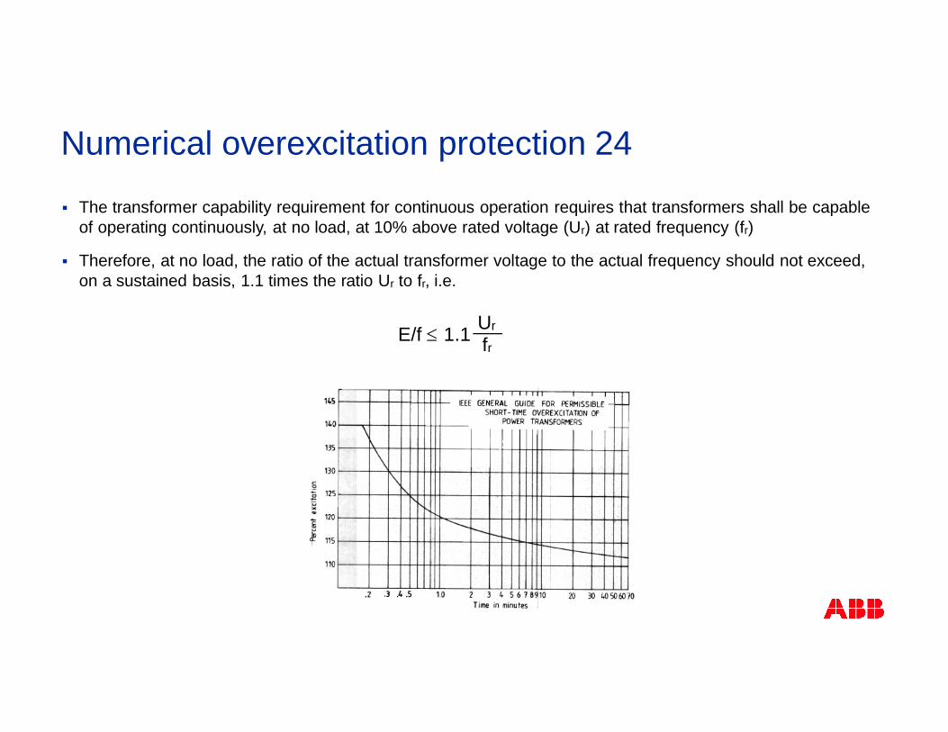
§ The transformer capability requirement for continuous operation requires that transformers shall be capableof operating continuously, at no load, at 10% above rated voltage (Ur) at rated frequency (fr)
§ Therefore, at no load, the ratio of the actual transformer voltage to the actual frequency should not exceed,on a sustained basis, 1.1 times the ratio Ur to fr, i.e.
frE/f £ Ur1.1
Numerical overexcitation protection 24
§ Relative excitation M
§ A power transformer is not overexcited as long as
1.1 (ABB = setting) is the maximum continuously allowed no-load voltage at rated frequency
§ Relative overexcitation is thus defined as
M =E/f
Ur/fr
M £ 1.1
overexcitation = M – 1.1
Numerical overexcitation protection 24
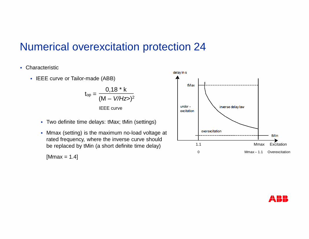
§ Characteristic
§ IEEE curve or Tailor-made (ABB)
§ Two definite time delays: tMax; tMin (settings)
§ Mmax (setting) is the maximum no-load voltage atrated frequency, where the inverse curve shouldbe replaced by tMin (a short definite time delay)
[Mmax = 1.4]
top =0,18 * k
(M – V/Hz>)2
IEEE curve
1.1 Mmax Excitation
0 Mmax – 1.1 Overexcitation
Numerical overexcitation protection 24
§ Overexcitation causes overheating, so cooling must be allowed for
(ABB: an exponential cooling feature has been implemented with setting for transformer magnetic corecooling time constant)
§ If an overexcitation condition should return before normal operating temperature is reached, the time to tripwould be shorter than for an overexcitation condition starting from a transformer at normal operatingtemperature
Numerical overexcitation protection 24
§ Temporary overloading necessary in stressed situations§ Not possible to design the system to manage all situations
§ Temporary overload not harmful
§ Hard decision for operator to disconnect the transformer
§ Consequences of overload§ Degrading in the quality of the transformer oil
§ Forced aging of insulation
§ Increase risk of internal faults
§ Hot spots within the transformer
§ Degrade paper insulation
Numerical thermal protection 49
§ Continuously estimate the internal heat content of the transformer
[ABB: estimation based on current measurement (true RMS) using a transformer thermal model withsettable time constant]
§ Two time constants / power ratings to handle operation with / without cooling
§ Features
§ Alarm (1 or more): given when the heat content ≥ (set) alarm level
§ Trip: given when the heat content ≥ (set) trip level
§ Lockout release: given after trip when the heat content ≤ (set) lockout release level
§ After tripping, the transformer will cool, taking some time before the heat content (temperature)reaches a level that the transformer can be put into service again – energizing the transformercan be blocked until the heat content has reached a set level
§ Provided information
§ Time to trip, time to lockout reset, warning at chosen time before trip
Numerical thermal protection 49
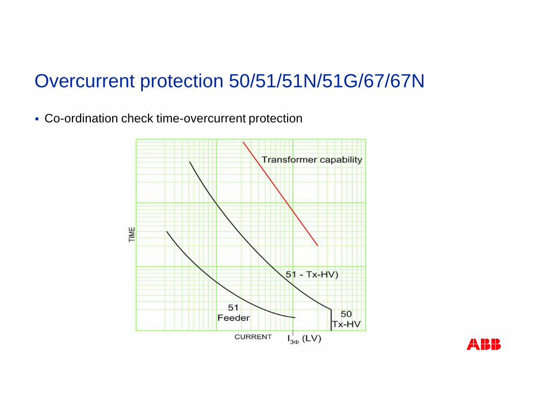
§ Instantaneous protection 50§ Fast operation on heavy internal faults
§ Pickup setting 125% of the maximum through fault (low side 3-phase fault)
§ Settings should be above the inrush current
§ Time-overcurrent protection 51/51N/51G§ Inverse time characteristic provides the best coordination
§ Pickup setting 200 to 300% of the transformer’s self-cooled rating
§ Fast operation is not possible (coordination with other relays)
Overcurrent protection 50/51/51N/51G/67/67N
Overcurrent protection 50/51/51N/51G/67/67N
§ Co-ordination check time-overcurrent protection
§ Designed to automatically maintain the voltage at the LV-side side of a powertransformer to within given limits around a set target voltage
§ A raise or lower command is generated whenever the measured voltage, for agiven period of time, deviates from the set target value by more than the presetdeadband value (i.e. degree of insensitivity)
§ A time delay (inverse or definite time) is set to avoid unnecessary operationduring shorter voltage deviations from the target value, and to coordinate withother automatic voltage controllers in the system
Voltage control function
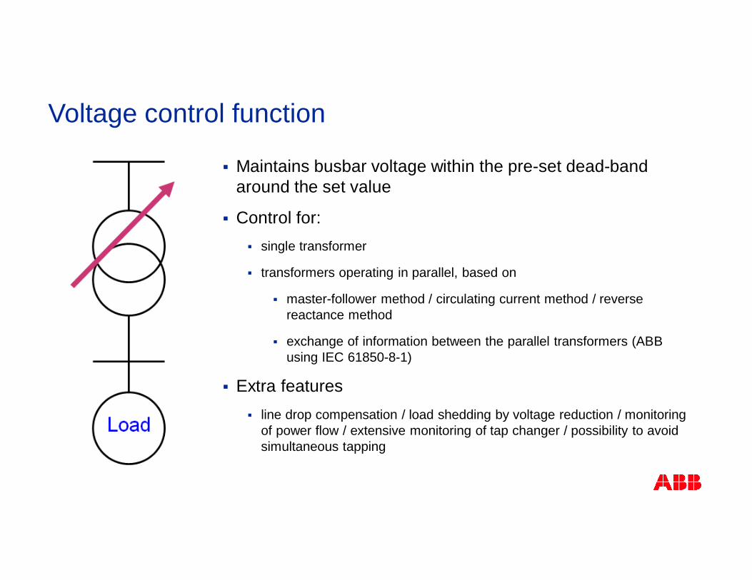
§ Maintains busbar voltage within the pre-set dead-bandaround the set value
§ Control for:§ single transformer
§ transformers operating in parallel, based on
§ master-follower method / circulating current method / reversereactance method
§ exchange of information between the parallel transformers (ABBusing IEC 61850-8-1)
§ Extra features§ line drop compensation / load shedding by voltage reduction / monitoring
of power flow / extensive monitoring of tap changer / possibility to avoidsimultaneous tapping
Voltage control function
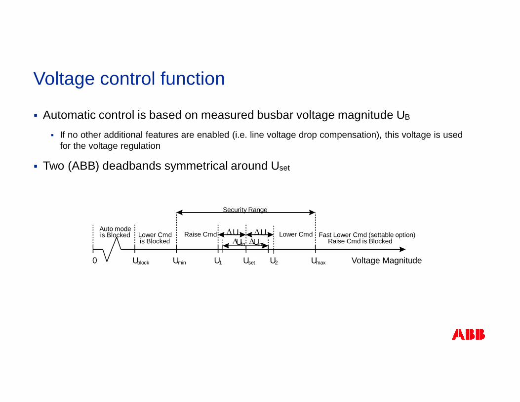
§ Automatic control is based on measured busbar voltage magnitude UB
§ If no other additional features are enabled (i.e. line voltage drop compensation), this voltage is usedfor the voltage regulation
§ Two (ABB) deadbands symmetrical around Uset
Voltage control function
Voltage MagnitudeUmaxUsetU1UminUblock0
Raise CmdLower Cmdis Blocked
Auto modeis Blocked
Security Range
Lower Cmd Fast Lower Cmd (settable option)Raise Cmd is Blocked
DDU UDUin DUin
U2
§ Measured voltage within the (outer) deadband, no action
§ Measured voltage outside the (outer) deadband, start the timer to initiate a tapcommand§ The timer will run as long as the measured voltage stays outside the (outer) deadband – if this
condition persists longer than the preset time delay, the appropriate tap command will be initiated
§ If necessary, the procedure will be repeated until the magnitude of the measuredvoltage is once again back inside the (inner) deadband
Voltage control function
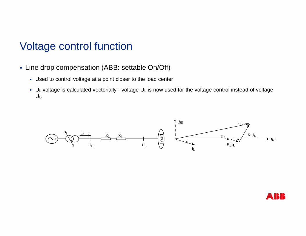
§ Line drop compensation (ABB: settable On/Off)§ Used to control voltage at a point closer to the load center
§ UL voltage is calculated vectorially - voltage UL is now used for the voltage control instead of voltageUB
UB
RL XL
UL
IL
Load
UB
UL
IL
j
jXLIL
RLILRe
Im
Voltage control function
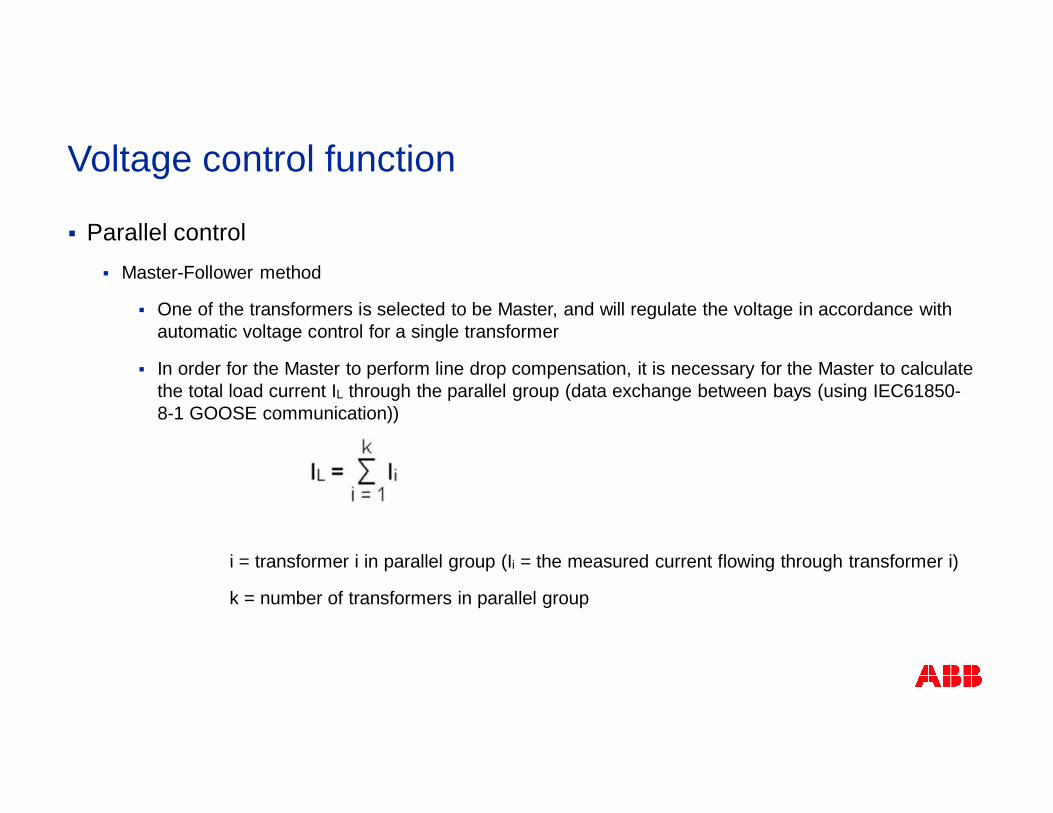
§ Parallel control§ Master-Follower method
§ One of the transformers is selected to be Master, and will regulate the voltage in accordance withautomatic voltage control for a single transformer
§ In order for the Master to perform line drop compensation, it is necessary for the Master to calculatethe total load current IL through the parallel group (data exchange between bays (using IEC61850-8-1 GOOSE communication))
i = transformer i in parallel group (Ii = the measured current flowing through transformer i)
k = number of transformers in parallel group
Voltage control function
§ Parallel control§ Circulating current method
§ Voltage control of parallel transformers using this method aims to minimize the circulatingcurrent at the given target value, thereby regulating the busbar, or load, voltage to the presettarget value
§ Requires extensive exchange of data between bays (using IEC61850-8-1 GOOSEcommunication)
Voltage control function
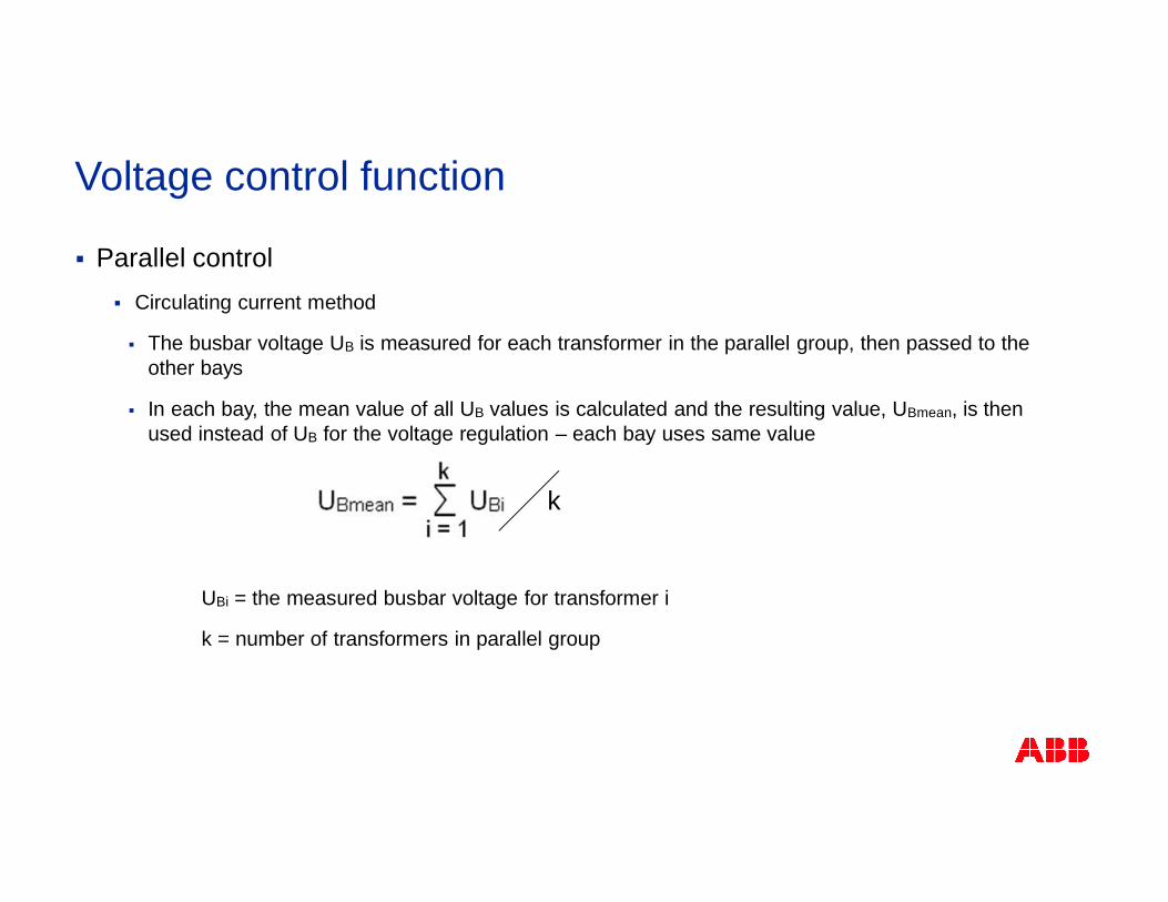
§ Parallel control§ Circulating current method
§ The busbar voltage UB is measured for each transformer in the parallel group, then passed to theother bays
§ In each bay, the mean value of all UB values is calculated and the resulting value, UBmean, is thenused instead of UB for the voltage regulation – each bay uses same value
UBi = the measured busbar voltage for transformer i
k = number of transformers in parallel group
k
Voltage control function
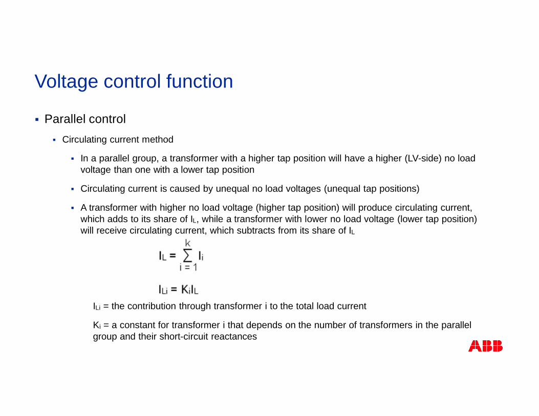
§ Parallel control§ Circulating current method
§ In a parallel group, a transformer with a higher tap position will have a higher (LV-side) no loadvoltage than one with a lower tap position
§ Circulating current is caused by unequal no load voltages (unequal tap positions)
§ A transformer with higher no load voltage (higher tap position) will produce circulating current,which adds to its share of IL, while a transformer with lower no load voltage (lower tap position)will receive circulating current, which subtracts from its share of IL
ILi = the contribution through transformer i to the total load current
Ki = a constant for transformer i that depends on the number of transformers in the parallelgroup and their short-circuit reactances
Voltage control function
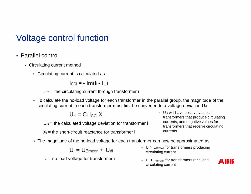
§ Parallel control§ Circulating current method
§ Circulating current is calculated as
ICCi = the circulating current through transformer i
§ To calculate the no-load voltage for each transformer in the parallel group, the magnitude of thecirculating current in each transformer must first be converted to a voltage deviation Udi
Udi = the calculated voltage deviation for transformer i
Xi = the short-circuit reactance for transformer i
§ The magnitude of the no-load voltage for each transformer can now be approximated as
Ui = no-load voltage for transformer i
§ Ui > UBmean for transformers producingcirculating current
§ Ui < UBmean for transformers receivingcirculating current
§ Udi will have positive values fortransformers that produce circulatingcurrents, and negative values fortransformers that receive circulatingcurrents
Voltage control function
§ Parallel control§ Circulating current method
§ The value for the no-load voltage is then simply put into the voltage control function, where it istreated as the measured busbar voltage, and further control actions are taken in accordancewith automatic voltage control for a single transformer
§ The calculated no-load voltage is compared with the set voltage Uset
§ A steady deviation outside the (outer) deadband will result in raise or lower commandsbeing given
§ In this way the overall control action is always correct as the tap changer position is directlyproportional to the transformer no-load voltage
§ Different Uset values for individual transformers can cause the voltage regulation to be unstable
§ For this reason, a mean value of Uset for the parallel operating transformers can be automaticallycalculated and used for the voltage regulation (ABB settable)
Voltage control function