Embed Size (px)
Citation preview
2015 IECC Commercial: Overview of the Envelope Requirements
Howard Wiig, Hawaii State Energy OfficeEric Makela, Cadmus

INTRODUCTIONSection I
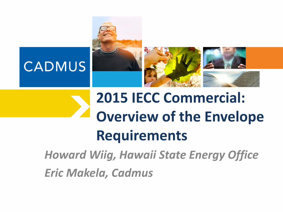
Structure of the 2015 IECC
– Structure of the code – need a slide that shows the different chapters of the code for residential and commercial
4
Table of ContentsResidential Provisions
Chapter 1 – Scope and Administration
Chapter 2 – Definitions
Chapter 3 – General Requirements
Chapter 4 – Residential Energy Efficiency
Chapter 5 – Existing Buildings
Chapter 6 – References Standards
Commercial ProvisionsChapter 1 – Scope and Administration
Chapter 2 – Definitions
Chapter 3 – General Requirements
Chapter 4 – Commercial Energy Efficiency
Chapter 5 – Existing Buildings
Chapter 6 – References Standards
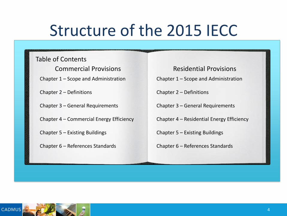
Energy Savings Potential for Adoption of the 2015 IECC
5
Cumulative Residential energy savings compared to
the 2006 IECC
• 2 GWh/yr in 2016• 369 GWh/yr in 2026• 687 GWh/yr in 2030• 1,317 GWh/yr in 2036
Cumulative Commercial energy savings compared to ASHRAE Standard 90.1-2004
• 11 GWh/yr in 2016 • 715 GWh/yr in 2026• 1,304 GWh/yr in 2030• 3,386 GWh/yr in 2036
Cumulative Net Savings
• 13 GWh/yr in 2016• 1,084 GWh/yr in 2026• 1,991 GWh/yr 2030• 4,703 GWh/yr in 2036
How Much is a Gigawatt:Power for approximately 200,000 homes for one year

GeneralSection R401
COMMERCIAL PROVISIONS: AN OVERVIEW
Section III
GeneralSection C401
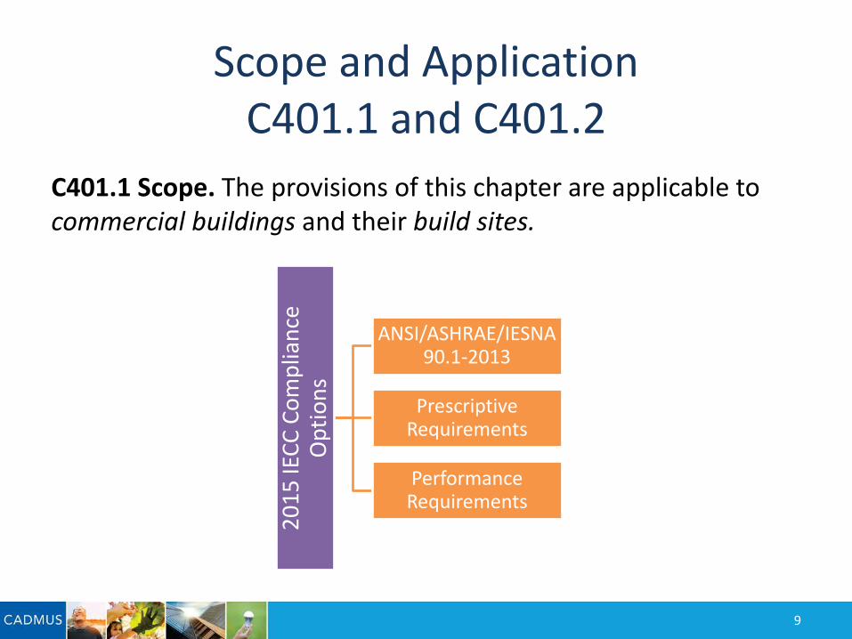
Scope and ApplicationC401.1 and C401.2
C401.1 Scope. The provisions of this chapter are applicable to commercial buildings and their build sites.
9
2015
IECC
Com
plia
nce
Opt
ions
ANSI/ASHRAE/IESNA 90.1-2013
Prescriptive Requirements
Performance Requirements
Building EnvelopeSection C402
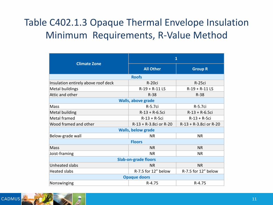
Table C402.1.3 Opaque Thermal Envelope Insulation Minimum Requirements, R-Value Method
Climate Zone1
All Other Group R
RoofsInsulation entirely above roof deck R-20ci R-25ciMetal buildings R-19 + R-11 LS R-19 + R-11 LSAttic and other R-38 R-38
Walls, above gradeMass R-5.7ci R-5.7ciMetal building R-13 + R-6.5ci R-13 + R-6.5ciMetal framed R-13 + R-5ci R-13 + R-5ciWood framed and other R-13 + R-3.8ci or R-20 R-13 + R-3.8ci or R-20
Walls, below gradeBelow-grade wall NR NR
FloorsMass NR NRJoist-framing NR NR
Slab-on-grade floorsUnheated slabs NR NRHeated slabs R-7.5 for 12” below R-7.5 for 12” below
Opaque doorsNonswinging R-4.75 R-4.75
11

Thermal Resistance of Above-Grade WallsC402.2.3 Hawaii Specific
C402.2.3 Thermal resistance of above-grade walls. The minimum thermal resistance (R-value) of materials installed in the wall cavity between framing members and continuously on the walls shall be as specific in Table C401.3, based on framing type and construction materials used in the wall assembly.Exceptions:Continuous insulation for wood and metal framed walls are not required when one of the following conditions are met:
– Walls have a covering with a reflectance of ≥ 0.64– Walls have overhangs with a projection factor equal to or greater than 0.3. The projection factor is
the horizontal distance from the surface of the wall to the farthest most point of the overhang divided by the vertical distance from the first floor level to the bottom most point of the overhang.
The R-value of integral insulation installed in concrete masonry units shall not be used in determining compliance with Table C402.1.3. Mass walls shall include walls:1. Weighing not less than 35 psf (170 kg/m2) of wall surface area.2. Weighing not less than 25 psf (120 kg/m2) of wall surface area where the material weight is not more
than 120 pcf (1900 kg/m3).3. Having a heat capacity exceeding 7 Btu/ft2·°F (144 cage/m2·K).4. Having a heat capacity exceeding 5 Btu/ft2·°F (103 kJ/m2·K), where the material weight is not more than
120 pcf (1900 kg/m3).
12
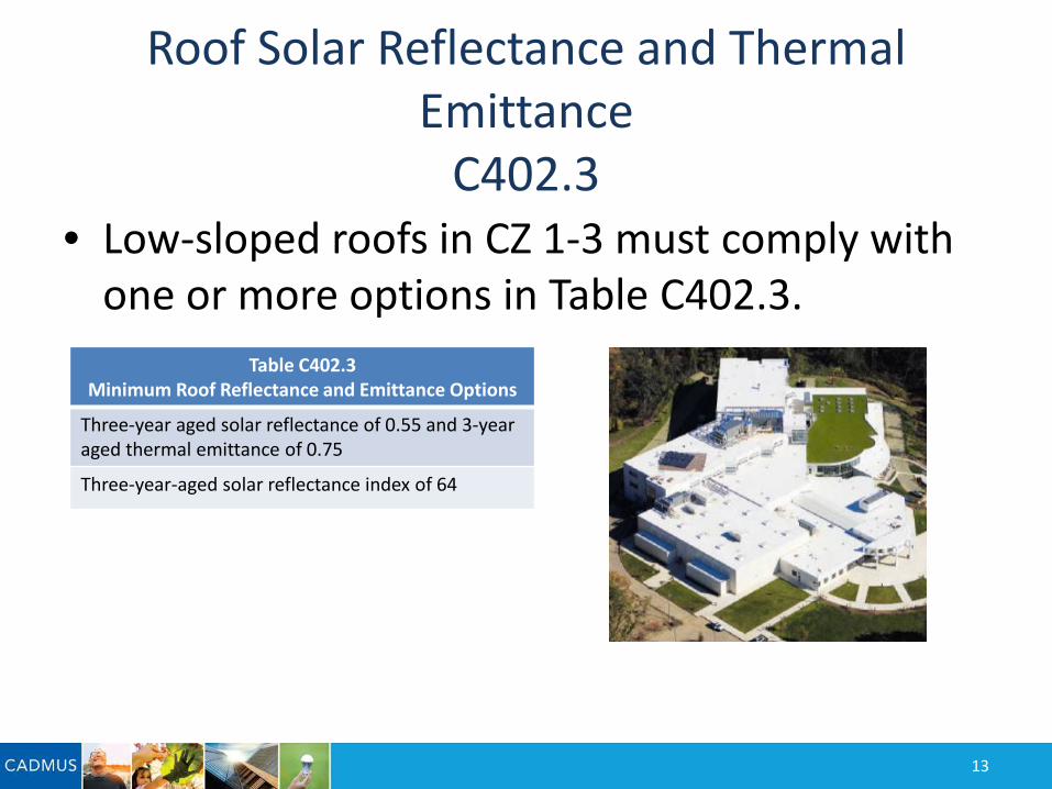
Roof Solar Reflectance and Thermal Emittance
C402.3• Low-sloped roofs in CZ 1-3 must comply with
one or more options in Table C402.3.
13
Table C402.3Minimum Roof Reflectance and Emittance Options
Three-year aged solar reflectance of 0.55 and 3-yearaged thermal emittance of 0.75
Three-year-aged solar reflectance index of 64
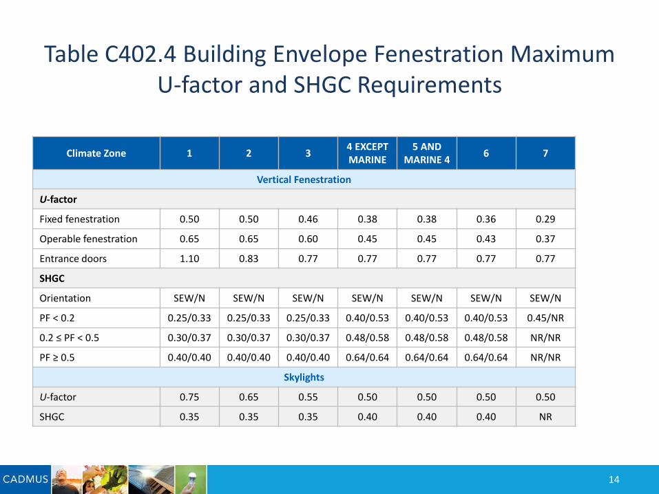
Table C402.4 Building Envelope Fenestration Maximum U-factor and SHGC Requirements
Climate Zone 1 2 3 4 EXCEPTMARINE
5 ANDMARINE 4 6 7
Vertical Fenestration
U-factor
Fixed fenestration 0.50 0.50 0.46 0.38 0.38 0.36 0.29
Operable fenestration 0.65 0.65 0.60 0.45 0.45 0.43 0.37
Entrance doors 1.10 0.83 0.77 0.77 0.77 0.77 0.77
SHGC
Orientation SEW/N SEW/N SEW/N SEW/N SEW/N SEW/N SEW/N
PF < 0.2 0.25/0.33 0.25/0.33 0.25/0.33 0.40/0.53 0.40/0.53 0.40/0.53 0.45/NR
0.2 ≤ PF < 0.5 0.30/0.37 0.30/0.37 0.30/0.37 0.48/0.58 0.48/0.58 0.48/0.58 NR/NR
PF ≥ 0.5 0.40/0.40 0.40/0.40 0.40/0.40 0.64/0.64 0.64/0.64 0.64/0.64 NR/NR
Skylights
U-factor 0.75 0.65 0.55 0.50 0.50 0.50 0.50
SHGC 0.35 0.35 0.35 0.40 0.40 0.40 NR
14
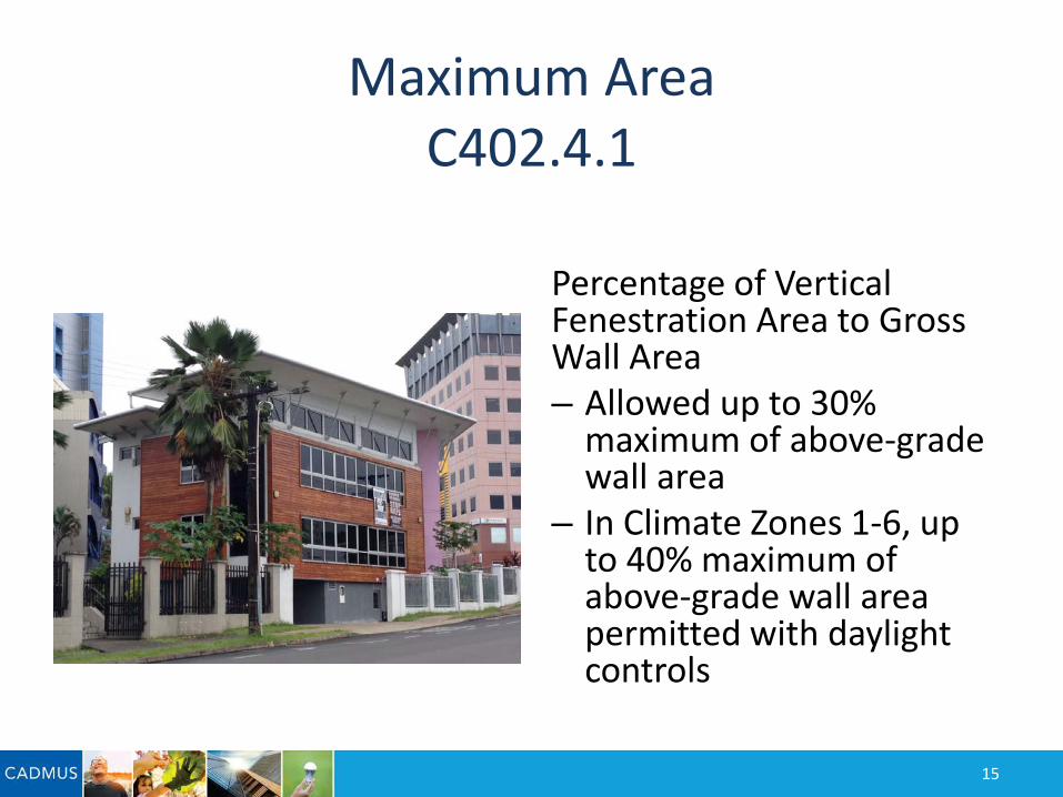
Maximum AreaC402.4.1
Percentage of Vertical Fenestration Area to Gross Wall Area– Allowed up to 30%
maximum of above-grade wall area
– In Climate Zones 1-6, up to 40% maximum of above-grade wall area permitted with daylight controls
15
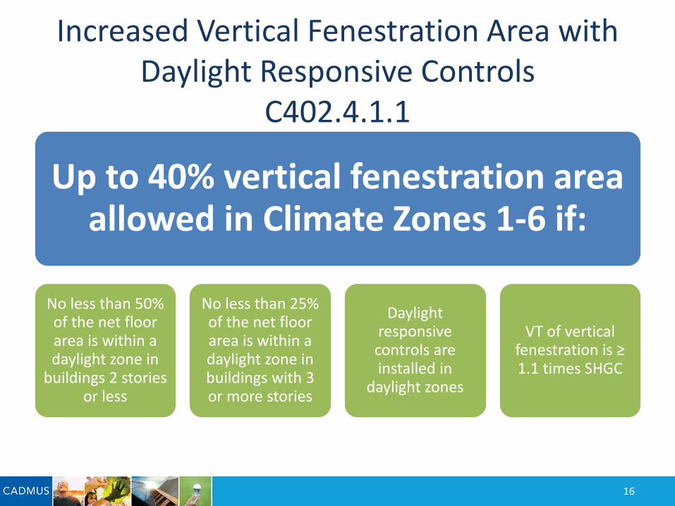
Increased Vertical Fenestration Area with Daylight Responsive Controls
C402.4.1.1
Up to 40% vertical fenestration area allowed in Climate Zones 1-6 if:
No less than 50% of the net floor area is within a daylight zone in
buildings 2 stories or less
No less than 25% of the net floor area is within a daylight zone in buildings with 3 or more stories
Daylight responsive controls are installed in
daylight zones
VT of vertical fenestration is ≥ 1.1 times SHGC
16
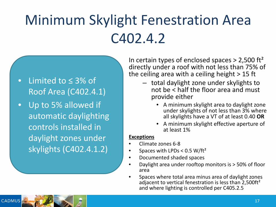
Minimum Skylight Fenestration AreaC402.4.2
17
In certain types of enclosed spaces > 2,500 ft² directly under a roof with not less than 75% of the ceiling area with a ceiling height > 15 ft
– total daylight zone under skylights to not be < half the floor area and must provide either
• A minimum skylight area to daylight zone under skylights of not less than 3% where all skylights have a VT of at least 0.40 OR
• A minimum skylight effective aperture of at least 1%
Exceptions • Climate zones 6-8 • Spaces with LPDs < 0.5 W/ft²• Documented shaded spaces • Daylight area under rooftop monitors is > 50% of floor
area• Spaces where total area minus area of daylight zones
adjacent to vertical fenestration is less than 2,500ft² and where lighting is controlled per C405.2.5
• Limited to ≤ 3% of Roof Area (C402.4.1)
• Up to 5% allowed if automatic daylighting controls installed in daylight zones under skylights (C402.4.1.2)
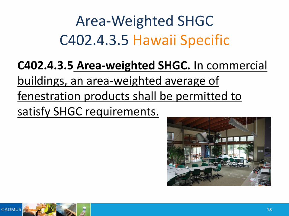
Area-Weighted SHGCC402.4.3.5 Hawaii Specific
C402.4.3.5 Area-weighted SHGC. In commercial buildings, an area-weighted average of fenestration products shall be permitted to satisfy SHGC requirements.
18
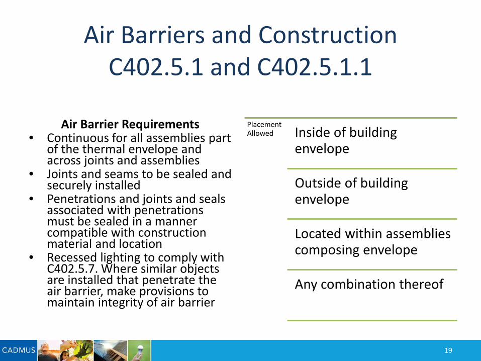
Air Barriers and ConstructionC402.5.1 and C402.5.1.1
Placement Allowed Inside of building
envelope
Outside of building envelope
Located within assemblies composing envelope
Any combination thereof
Air Barrier Requirements • Continuous for all assemblies part
of the thermal envelope and across joints and assemblies
• Joints and seams to be sealed and securely installed
• Penetrations and joints and seals associated with penetrations must be sealed in a manner compatible with construction material and location
• Recessed lighting to comply with C402.5.7. Where similar objects are installed that penetrate the air barrier, make provisions to maintain integrity of air barrier
19
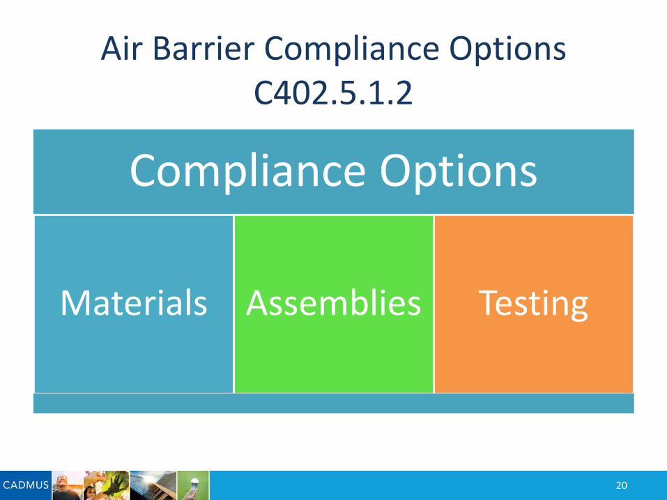
Air Barrier Compliance OptionsC402.5.1.2
Compliance Options
Materials Assemblies Testing
20
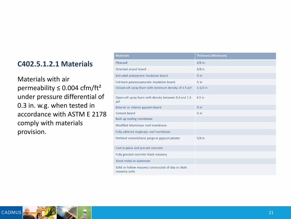
C402.5.1.2.1 Materials
Materials with air permeability ≤ 0.004 cfm/ft² under pressure differential of 0.3 in. w.g. when tested in accordance with ASTM E 2178 comply with materials provision.
21
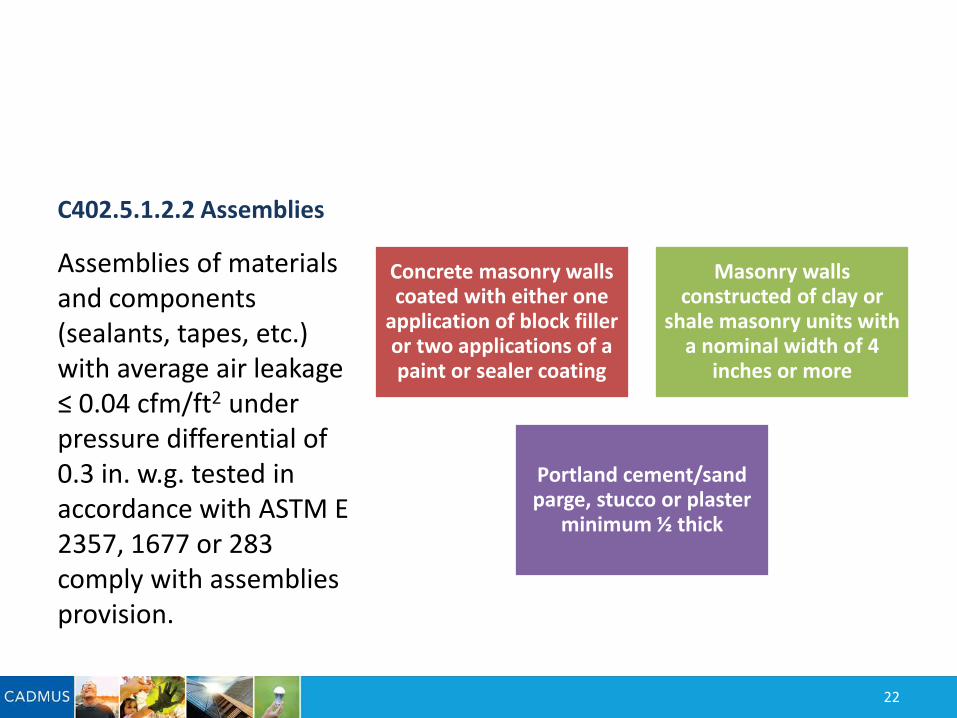
C402.5.1.2.2 Assemblies
Concrete masonry walls coated with either one
application of block filler or two applications of a paint or sealer coating
Masonry walls constructed of clay or
shale masonry units with a nominal width of 4
inches or more
Portland cement/sand parge, stucco or plaster
minimum ½ thick
Assemblies of materials and components (sealants, tapes, etc.) with average air leakage ≤ 0.04 cfm/ft2 under pressure differential of 0.3 in. w.g. tested in accordance with ASTM E 2357, 1677 or 283 comply with assemblies provision.
22
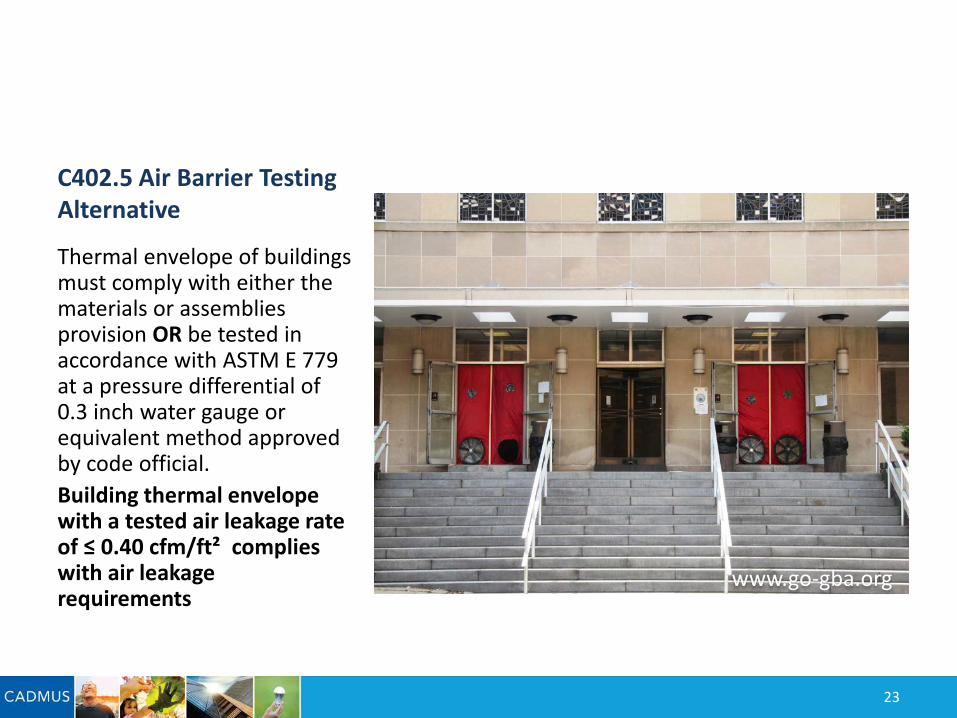
C402.5 Air Barrier Testing Alternative
Thermal envelope of buildings must comply with either the materials or assemblies provision OR be tested in accordance with ASTM E 779 at a pressure differential of 0.3 inch water gauge or equivalent method approved by code official.Building thermal envelope with a tested air leakage rate of ≤ 0.40 cfm/ft² complies with air leakage requirements
23
www.go-gba.org
Additional Efficiency Package Options
Section C406
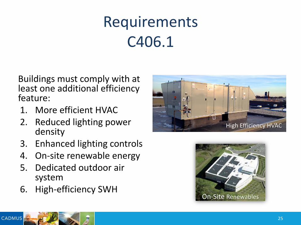
Requirements C406.1
Buildings must comply with at least one additional efficiency feature:1. More efficient HVAC2. Reduced lighting power
density3. Enhanced lighting controls4. On-site renewable energy5. Dedicated outdoor air
system6. High-efficiency SWH
25
On-Site Renewables
High Efficiency HVAC