Embed Size (px)
Citation preview
PNNL-20263
Prepared for the U.S. Department of Energy under Contract DE-AC05-76RL01830
Comparison of 2006 IECC and 2009 IECC Commercial Energy Code Requirements for Kansas City, MO Y Huang K Gowri March 2011
PNNL-20263 Comparison of 2006 IECC and 2009 IECC Commercial Energy Code Requirements for Kansas City, MO Y Huang K Gowri March 2011 Prepared for U.S. Department of Energy under Contract DE-AC05-76RL01830 Pacific Northwest National Laboratory Richland, Washington 99352

Executive Summary
This report summarizes code requirements and energy savings of commercial buildings in Climate Zone 4 built to the 2009 IECC when compared to the 2006 IECC. In general, the 2009 IECC has higher insulation requirements for exterior walls, roof, and windows and has higher efficiency requirements for heating, ventilation and air-conditioning (HVAC) equipment. HVAC equipment efficiency requirements are governed by the National Appliance Energy Conservation Act of 1987 (NAECA), and are applicable irrespective of the IECC version adopted. The energy analysis results show that residential and nonresidential commercial buildings meeting the 2009 IECC requirements save 9.0% and 6.1% site energy, and 7.7% and 6.4% energy cost when compared to the 2006 IECC. Analysis also shows that semiheated buildings have energy and cost savings of 3.9% and 2.5%.
iii

iv
Table of Contents Executive Summary ....................................................................................................................... iii 1. Background and Scope ............................................................................................................ 1 2. Comparison of Code Requirements ......................................................................................... 3 3. Energy Analysis ....................................................................................................................... 7 4. Conclusions ........................................................................................................................... 11 Appendix A – Detailed Comparison of Code Requirements ...................................................... A.1 Appendix B – Prototype Building Descriptions .......................................................................... B.1
v
vi
Tables Table 1: Comparison of Envelope Requirements ........................................................................... 5 Table 2: Comparison of Mechanical and Lighting Requirements .................................................. 6 Table 3: Utility Tariffs used for Kansas City (2010-2011) ............................................................. 8 Table 4: Energy Impact Summary .................................................................................................. 9 Table 5: Utility Cost and Environmental Impact Summary ........................................................... 9 Table 6: Energy, Utility Cost and Environmental Reduction (percentage) .................................. 11 Table A.1: Comparison of Code Requirements .......................................................................... A.1 Table B.1: Residential Prototype Building Characteristics ......................................................... B.1 Table B.2: Non-residential Prototype Building Characteristics .................................................. B.3 Table B.3: Semi-heated Prototype Building Characteristics ....................................................... B.5
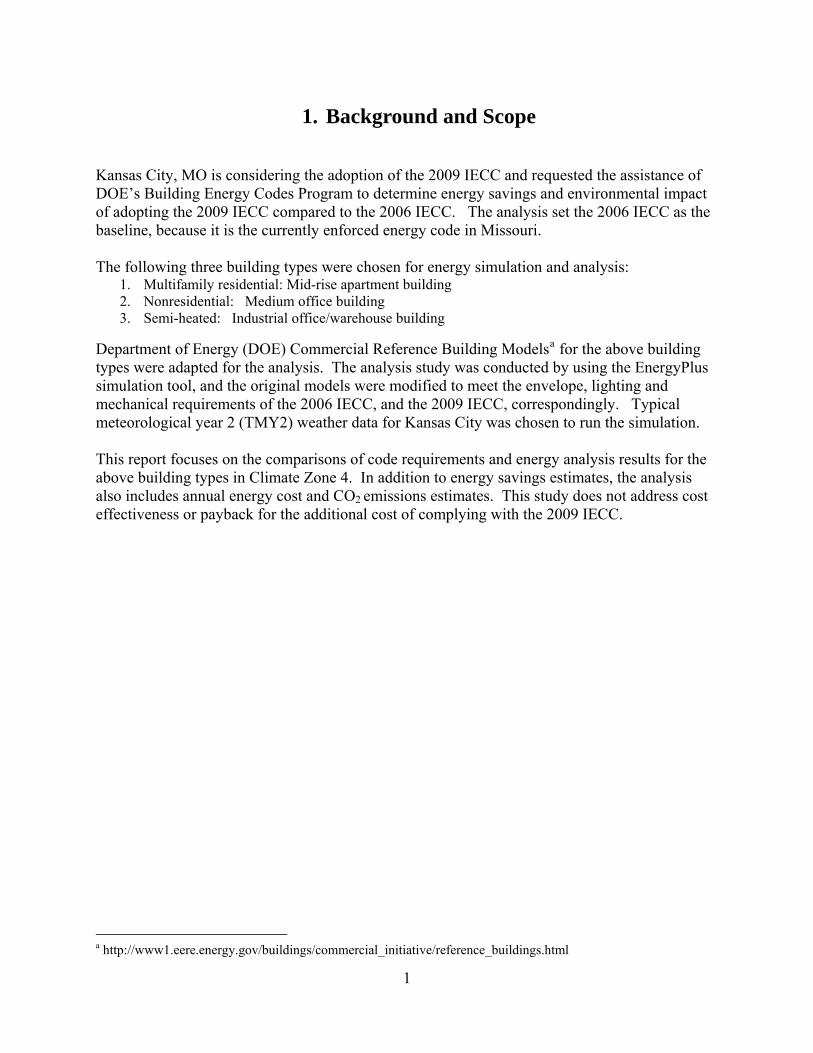
1. Background and Scope Kansas City, MO is considering the adoption of the 2009 IECC and requested the assistance of DOE’s Building Energy Codes Program to determine energy savings and environmental impact of adopting the 2009 IECC compared to the 2006 IECC. The analysis set the 2006 IECC as the baseline, because it is the currently enforced energy code in Missouri. The following three building types were chosen for energy simulation and analysis:
1. Multifamily residential: Mid-rise apartment building 2. Nonresidential: Medium office building 3. Semi-heated: Industrial office/warehouse building
Department of Energy (DOE) Commercial Reference Building Modelsa for the above building types were adapted for the analysis. The analysis study was conducted by using the EnergyPlus simulation tool, and the original models were modified to meet the envelope, lighting and mechanical requirements of the 2006 IECC, and the 2009 IECC, correspondingly. Typical meteorological year 2 (TMY2) weather data for Kansas City was chosen to run the simulation. This report focuses on the comparisons of code requirements and energy analysis results for the above building types in Climate Zone 4. In addition to energy savings estimates, the analysis also includes annual energy cost and CO2 emissions estimates. This study does not address cost effectiveness or payback for the additional cost of complying with the 2009 IECC.
a http://www1.eere.energy.gov/buildings/commercial_initiative/reference_buildings.html
1

2
2. Comparison of Code Requirements The commercial code requirements in the 2006 IECC and the 2009 IECC for envelope, mechanical and lighting systems are listed in Tables 1 and 2. The envelope insulation and fenestration requirements for Kansas City, MO are specified in the 2009 IECC Tables 502.1.2, 502.2 and 502.3 for Climate Zone 4 (except Marine), representing the requirements for Jackson County (Climate Zone 4A). The scope of comparison is limited to building characteristics that can be modeled for detailed energy simulation and analysis. The 2009 IECC includes a number of significant changes to commercial building requirements in Chapter 5. The most important changes include the introduction of the envelope U‐factor table, Group R specific envelope requirements, HVAC minimum efficiency requirements, economizer requirements, pipe insulation requirements and exterior lighting requirements. Appendix‐A provides a detailed comparison of all the changes between the 2006 IECC and 2009 IECC Chapter 5.
A qualitative summary of the 2009 IECC changes are listed below:
• Alternative compliance using ASHRAE/IESNA 90.1 requires the use of 90.1‐2007 (instead of 90.1‐2004).
• More stringent envelope requirements are included for “Group R” buildings, in addition to more stringent opaque envelope requirements for all commercial buildings in all climate zones.
• The opaque requirements for roof, above-grade walls and floors are more stringent in the 2009 IECC, but the below grade wall assemblies and fenestration requirements remain the same as 2006 IECC.
• Metal building insulation requirements have been revised to be more stringent and require mandatory continuous insulation sheathing on metal building walls.
• Plastic skylights requirements are removed and all skylights are required to meet more stringent U‐factor and solar heat gain coefficient (SHGC) requirements.
• All recessed lighting is required to be IC‐rated and sealed.
• HVAC equipment efficiency requirements for unitary air conditioners, chilled water systems and boilers have been revised to be more stringent. The minimum efficiency requirements for unitary air‐conditioners is seasonal energy efficiency rating (SEER) 13.0 for the 2009 IECC compared to SEER 10.0 in the 2006 IECC. (These are based on NAECA requirements and are applicable irrespective of the version of IECC adopted.)
• Piping insulation requirements have been revised and 1 ½ inch insulation is required for all pipes with nominal pipe diameter less than or equal to 1 ½ inch.
• A new fan power requirements section has been added and fan power limitations are included.
• Economizer requirements have been revised to require economizers when cooling capacity exceeds 54 kBtu/h in all climate zones except 1, 2A, 7 and 8.
3
• Heat rejection equipment requirements have been revised based on climate zone, and a new exception is provided if a heat pump is used to reject heat throughout the year.
• A new requirement has been added for supply‐air temperature reset controls to reset the supply air temperature based on building loads or outdoor air temperature.
• Lighting exemption for dwelling units is provided if high‐efficacy lamps are used in at least 50% of all the permanent fixtures.
• A new section has been added requiring manual daylight zone controls in zones adjacent to vertical fenestration and zones with skylights.
• The interior lighting power requirements exemption list has been revised and expanded to specify more detailed functions such as photographic process, lighting in refrigerator/ freezer cases, and furniture-mounted task lighting that is controlled by automatic shut off.
• Interior lighting power allowance adjustments have been revised for retail display based on the type of products on display.
• Lighting-zone-based power allowance requirements are specified for exterior lighting.
4
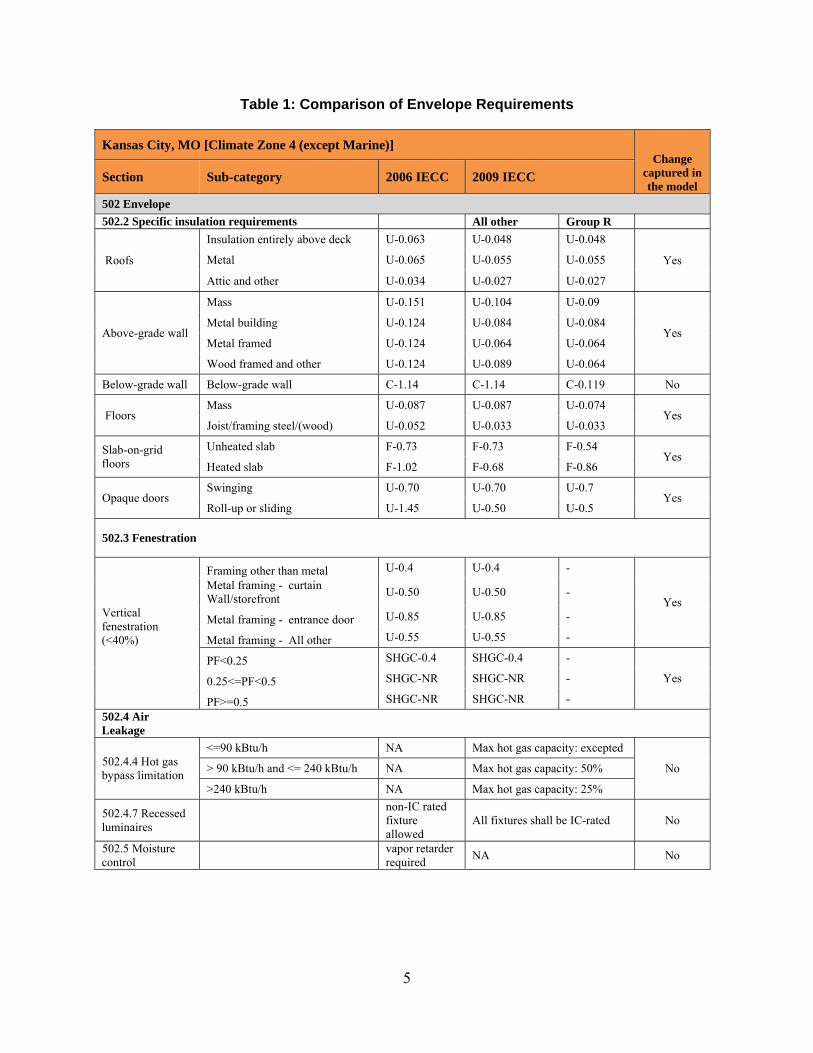
Table 1: Comparison of Envelope Requirements
Kansas City, MO [Climate Zone 4 (except Marine)] Change
captured in the model
Section Sub-category 2006 IECC 2009 IECC
502 Envelope 502.2 Specific insulation requirements All other Group R
Roofs
Insulation entirely above deck U-0.063 U-0.048 U-0.048
Yes Metal U-0.065 U-0.055 U-0.055
Attic and other U-0.034 U-0.027 U-0.027
Above-grade wall
Mass U-0.151 U-0.104 U-0.09
Yes Metal building U-0.124 U-0.084 U-0.084
Metal framed U-0.124 U-0.064 U-0.064
Wood framed and other U-0.124 U-0.089 U-0.064
Below-grade wall Below-grade wall C-1.14 C-1.14 C-0.119 No
Floors Mass U-0.087 U-0.087 U-0.074
Yes Joist/framing steel/(wood) U-0.052 U-0.033 U-0.033
Slab-on-grid floors
Unheated slab F-0.73 F-0.73 F-0.54 Yes
Heated slab F-1.02 F-0.68 F-0.86
Opaque doors Swinging U-0.70 U-0.70 U-0.7
Yes Roll-up or sliding U-1.45 U-0.50 U-0.5
502.3 Fenestration
Vertical fenestration (<40%)
Framing other than metal U-0.4 U-0.4 -
Yes Metal framing - curtain Wall/storefront U-0.50 U-0.50 -
Metal framing - entrance door U-0.85 U-0.85 -
Metal framing - All other U-0.55 U-0.55 -
PF<0.25 SHGC-0.4 SHGC-0.4 -
Yes 0.25<=PF<0.5 SHGC-NR SHGC-NR -
PF>=0.5 SHGC-NR SHGC-NR - 502.4 Air Leakage
502.4.4 Hot gas bypass limitation
<=90 kBtu/h NA Max hot gas capacity: excepted
No > 90 kBtu/h and <= 240 kBtu/h NA Max hot gas capacity: 50%
>240 kBtu/h NA Max hot gas capacity: 25%
502.4.7 Recessed luminaires
non-IC rated fixture allowed
All fixtures shall be IC-rated No
502.5 Moisture control
vapor retarder required NA No
5
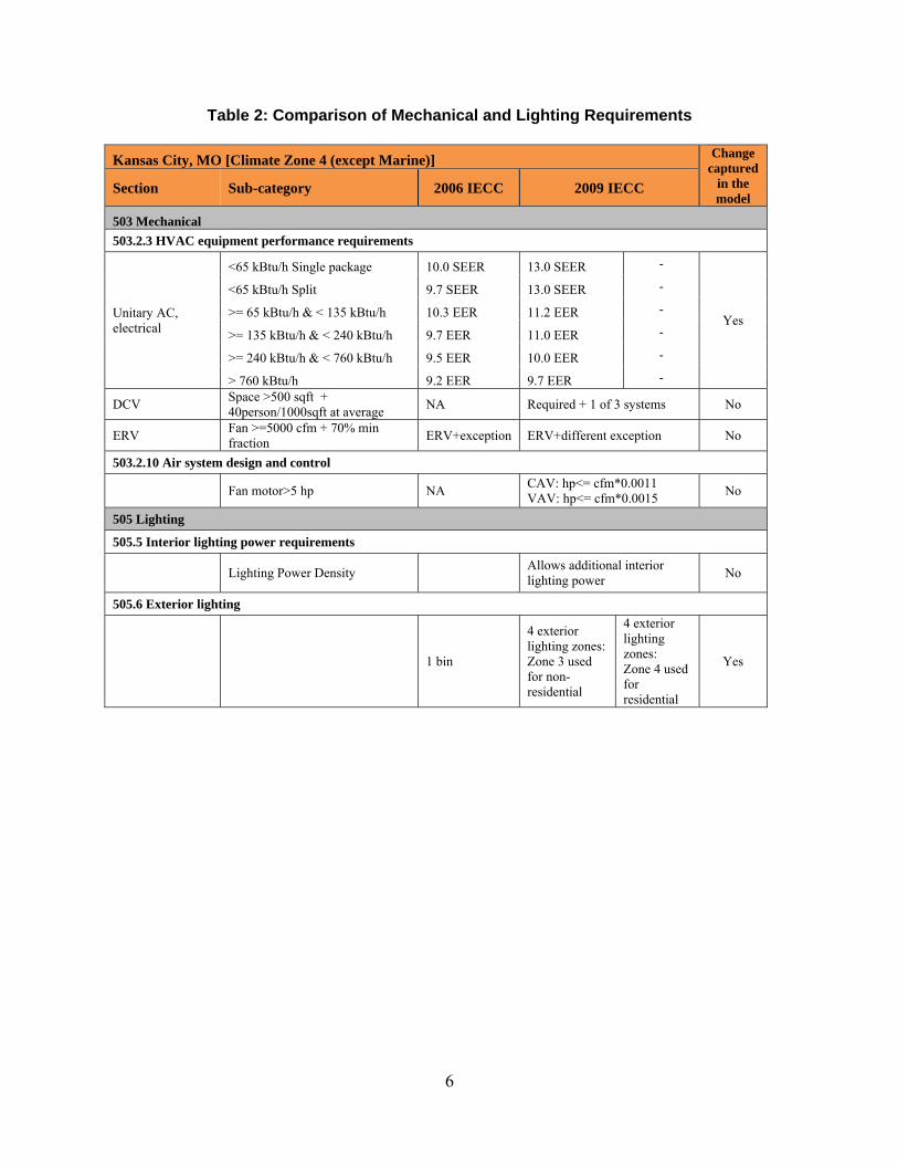
Table 2: Comparison of Mechanical and Lighting Requirements Kansas City, MO [Climate Zone 4 (except Marine)] Change
captured in the model
Section Sub-category 2006 IECC 2009 IECC
503 Mechanical 503.2.3 HVAC equipment performance requirements
Unitary AC, electrical
<65 kBtu/h Single package 10.0 SEER 13.0 SEER -
Yes
<65 kBtu/h Split 9.7 SEER 13.0 SEER -
>= 65 kBtu/h & < 135 kBtu/h 10.3 EER 11.2 EER -
>= 135 kBtu/h & < 240 kBtu/h 9.7 EER 11.0 EER -
>= 240 kBtu/h & < 760 kBtu/h 9.5 EER 10.0 EER -
> 760 kBtu/h 9.2 EER 9.7 EER -
DCV Space >500 sqft + 40person/1000sqft at average NA Required + 1 of 3 systems No
ERV Fan >=5000 cfm + 70% min fraction ERV+exception ERV+different exception No
503.2.10 Air system design and control
Fan motor>5 hp NA CAV: hp<= cfm*0.0011 VAV: hp<= cfm*0.0015 No
505 Lighting
505.5 Interior lighting power requirements
Lighting Power Density
Allows additional interior lighting power No
505.6 Exterior lighting
1 bin
4 exterior lighting zones:Zone 3 used for non-residential
4 exterior lighting zones: Zone 4 used for residential
Yes
6
3. Energy Analysis The impact of code requirements is quantified by analyzing building models representing the envelope, lighting and mechanical requirements identified in the comparison Tables 1 and 2. DOE Reference Building models for four representative building types were used for the analysis. A brief description of each of the building type is below:
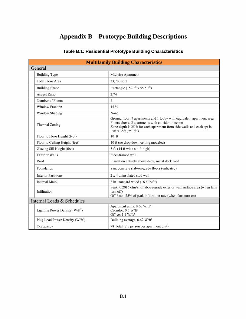
1. Residential – Multifamily/Midrise apartment building (33,700 sf): This is a four-story building with 15% window-wall ratio. This building is assumed to have steel frame walls, metal deck rook with insulation above deck and a slab-on-grade floor. Each apartment unit is assumed to have a packaged air-conditioning unit with a gas furnace and a 20-gallon electric service water heating system. More details of the thermal model with the baseline properties are listed in Appendix-A, Table A-1.
2. Nonresidential – Medium office building (53,600 sf): This is a three-story building with 33% window-wall ratio. This building is assumed to have steel frame walls, metal deck rook with insulation above deck and a slab-on-grade floor. The HVAC system is a multi-zone VAV system with electric reheat, and packaged air-conditioner with gas furnace. Service water heating is assumed to be 260-gallon gas water heating. Further details on the energy model are provided in Appendix-A, Table A-2.
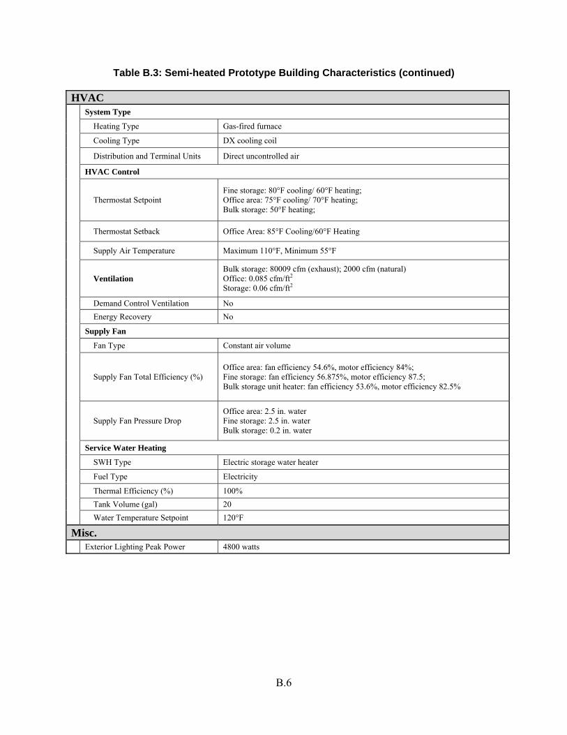
3. Semiheated – Large warehouse building (52,045 sf): This is a non-refrigerated warehouse building with an office area, fine storage and bulk storage areas. This building is assumed to have metal building walls, metal deck rook with insulation above deck and a slab-on-grade floor. The office area is conditioned by a packaged air-conditioning unit with a gas furnace, and the storage areas are heated with a natural gas unit heater. Service water heating is assumed to be a 20-gallon electric storage water heater.
Hourly energy simulation of the building model was performed for each of codes: the 2006 IECC and the 2009 IECC. EnergyPlus simulation software was used for the analysis. A typical design day simulation was done to determine the HVAC equipment size and then the annual simulation was run to determine the building energy use. The total building site energy is extracted from the simulation results for code comparisons. To assess the economic impacts of the code requirements, current utility tariffs for Kansas Cityb are used to calculate the total annual energy cost. Table 3 shows the fuel prices, demand charges and rate structure used, assuming a basic rate plan.
b http://www.ameren.com/sites/aue/MyHome/ResidentialRates/Pages/default.aspx http://www.ameren.com/sites/aue/MyBusiness/BusinessRates/Pages/Businessrates.aspx
7
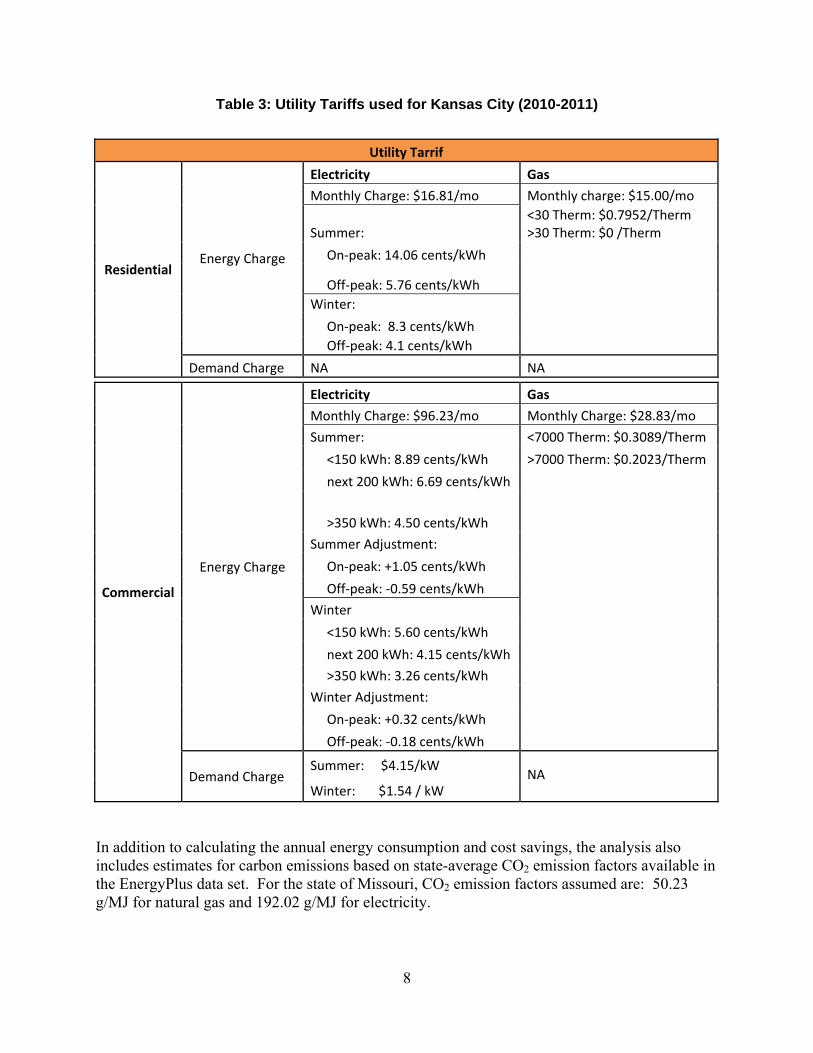
Table 3: Utility Tariffs used for Kansas City (2010-2011)
Utility Tarrif
Residential Energy Charge
Electricity Gas
Monthly Charge: $16.81/mo Monthly charge: $15.00/mo
Summer: <30 Therm: $0.7952/Therm >30 Therm: $0 /Therm
On‐peak: 14.06 cents/kWh
Off‐peak: 5.76 cents/kWh Winter:
On‐peak: 8.3 cents/kWh Off‐peak: 4.1 cents/kWh
Demand Charge NA NA
Commercial
Energy Charge
Electricity Gas
Monthly Charge: $96.23/mo Monthly Charge: $28.83/mo
Summer: <7000 Therm: $0.3089/Therm
<150 kWh: 8.89 cents/kWh >7000 Therm: $0.2023/Therm
next 200 kWh: 6.69 cents/kWh
>350 kWh: 4.50 cents/kWh
Summer Adjustment:
On‐peak: +1.05 cents/kWh
Off‐peak: ‐0.59 cents/kWh
Winter
<150 kWh: 5.60 cents/kWh
next 200 kWh: 4.15 cents/kWh
>350 kWh: 3.26 cents/kWh
Winter Adjustment:
On‐peak: +0.32 cents/kWh
Off‐peak: ‐0.18 cents/kWh
Demand Charge Summer: $4.15/kW
NA Winter: $1.54 / kW
In addition to calculating the annual energy consumption and cost savings, the analysis also includes estimates for carbon emissions based on state-average CO2 emission factors available in the EnergyPlus data set. For the state of Missouri, CO2 emission factors assumed are: 50.23 g/MJ for natural gas and 192.02 g/MJ for electricity.
8
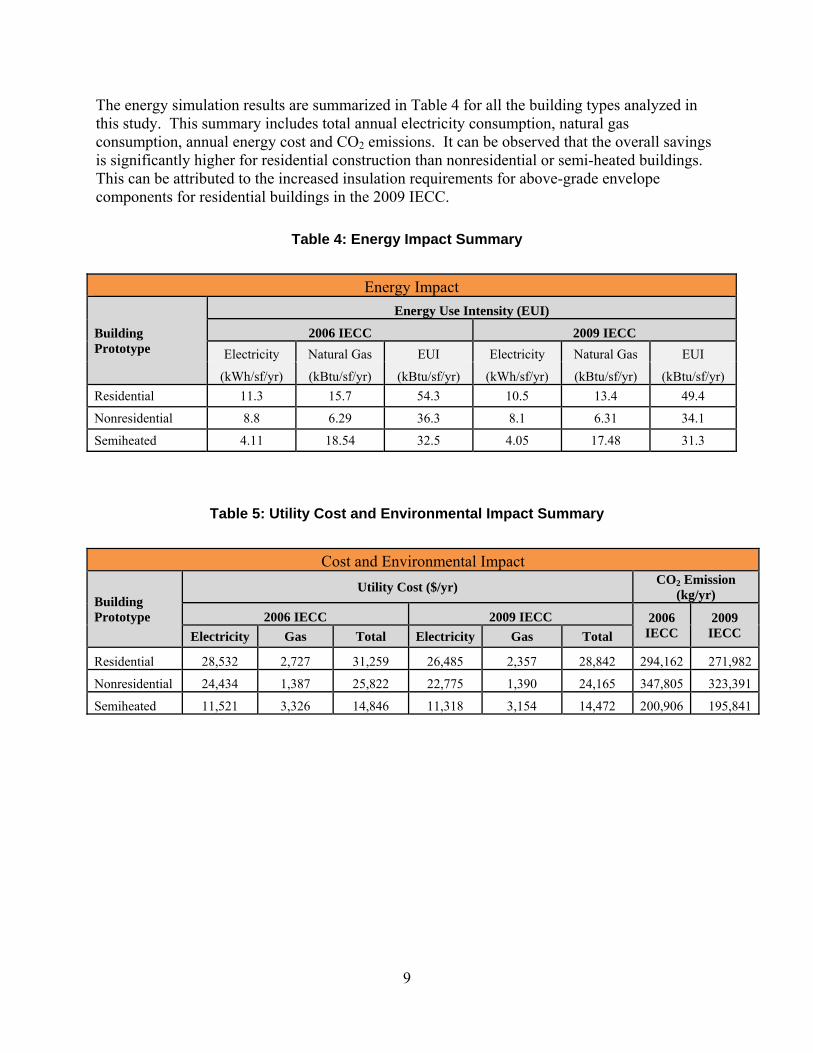
The energy simulation results are summarized in Table 4 for all the building types analyzed in this study. This summary includes total annual electricity consumption, natural gas consumption, annual energy cost and CO2 emissions. It can be observed that the overall savings is significantly higher for residential construction than nonresidential or semi-heated buildings. This can be attributed to the increased insulation requirements for above-grade envelope components for residential buildings in the 2009 IECC.
Table 4: Energy Impact Summary
Energy Impact
Building Prototype
Energy Use Intensity (EUI)
2006 IECC 2009 IECC Electricity Natural Gas EUI Electricity Natural Gas EUI
(kWh/sf/yr) (kBtu/sf/yr) (kBtu/sf/yr) (kWh/sf/yr) (kBtu/sf/yr) (kBtu/sf/yr) Residential 11.3 15.7 54.3 10.5 13.4 49.4
Nonresidential 8.8 6.29 36.3 8.1 6.31 34.1
Semiheated 4.11 18.54 32.5 4.05 17.48 31.3
Table 5: Utility Cost and Environmental Impact Summary
Cost and Environmental Impact
Building Prototype
Utility Cost ($/yr) CO2 Emission (kg/yr)
2006 IECC 2009 IECC 2006 IECC
2009 IECC Electricity Gas Total Electricity Gas Total
Residential 28,532 2,727 31,259 26,485 2,357 28,842 294,162 271,982
Nonresidential 24,434 1,387 25,822 22,775 1,390 24,165 347,805 323,391
Semiheated 11,521 3,326 14,846 11,318 3,154 14,472 200,906 195,841
9

10
4. Conclusions
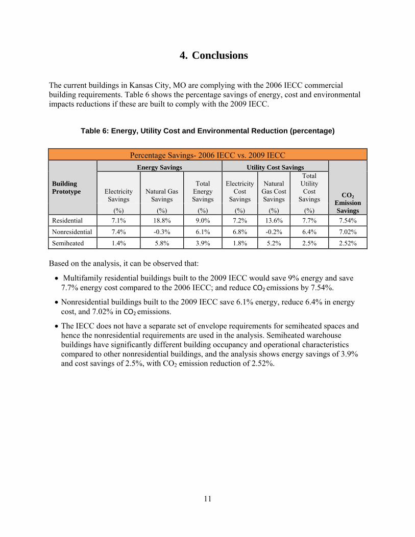
The current buildings in Kansas City, MO are complying with the 2006 IECC commercial building requirements. Table 6 shows the percentage savings of energy, cost and environmental impacts reductions if these are built to comply with the 2009 IECC.
Table 6: Energy, Utility Cost and Environmental Reduction (percentage)
Percentage Savings- 2006 IECC vs. 2009 IECC
Building Prototype
Energy Savings Utility Cost Savings
CO2 Emission Savings
Electricity Savings
Natural Gas Savings
Total Energy Savings
Electricity Cost
Savings
Natural Gas Cost Savings
Total Utility Cost
Savings
(%) (%) (%) (%) (%) (%) Residential 7.1% 18.8% 9.0% 7.2% 13.6% 7.7% 7.54%
Nonresidential 7.4% -0.3% 6.1% 6.8% -0.2% 6.4% 7.02%
Semiheated 1.4% 5.8% 3.9% 1.8% 5.2% 2.5% 2.52%
Based on the analysis, it can be observed that:
• Multifamily residential buildings built to the 2009 IECC would save 9% energy and save 7.7% energy cost compared to the 2006 IECC; and reduce CO2 emissions by 7.54%.
• Nonresidential buildings built to the 2009 IECC save 6.1% energy, reduce 6.4% in energy cost, and 7.02% in CO2 emissions.
• The IECC does not have a separate set of envelope requirements for semiheated spaces and hence the nonresidential requirements are used in the analysis. Semiheated warehouse buildings have significantly different building occupancy and operational characteristics compared to other nonresidential buildings, and the analysis shows energy savings of 3.9% and cost savings of 2.5%, with CO2 emission reduction of 2.52%.
11

12
Appendix A Detailed Comparison of Code Requirements

Appendix A – Detailed Comparison of Code Requirements
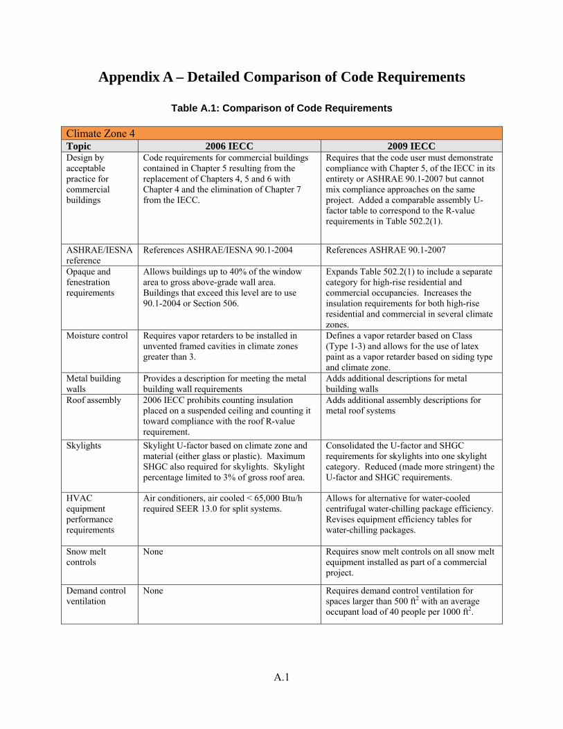
Table A.1: Comparison of Code Requirements Climate Zone 4 Topic 2006 IECC 2009 IECC Design by acceptable practice for commercial buildings
Code requirements for commercial buildings contained in Chapter 5 resulting from the replacement of Chapters 4, 5 and 6 with Chapter 4 and the elimination of Chapter 7 from the IECC.
Requires that the code user must demonstrate compliance with Chapter 5, of the IECC in its entirety or ASHRAE 90.1-2007 but cannot mix compliance approaches on the same project. Added a comparable assembly U-factor table to correspond to the R-value requirements in Table 502.2(1).
ASHRAE/IESNA reference
References ASHRAE/IESNA 90.1-2004 References ASHRAE 90.1-2007
Opaque and fenestration requirements
Allows buildings up to 40% of the window area to gross above-grade wall area. Buildings that exceed this level are to use 90.1-2004 or Section 506.
Expands Table 502.2(1) to include a separate category for high-rise residential and commercial occupancies. Increases the insulation requirements for both high-rise residential and commercial in several climate zones.
Moisture control
Requires vapor retarders to be installed in unvented framed cavities in climate zones greater than 3.
Defines a vapor retarder based on Class (Type 1-3) and allows for the use of latex paint as a vapor retarder based on siding type and climate zone.
Metal building walls
Provides a description for meeting the metal building wall requirements
Adds additional descriptions for metal building walls
Roof assembly 2006 IECC prohibits counting insulation placed on a suspended ceiling and counting it toward compliance with the roof R-value requirement.
Adds additional assembly descriptions for metal roof systems
Skylights
Skylight U-factor based on climate zone and material (either glass or plastic). Maximum SHGC also required for skylights. Skylight percentage limited to 3% of gross roof area.
Consolidated the U-factor and SHGC requirements for skylights into one skylight category. Reduced (made more stringent) the U-factor and SHGC requirements.
HVAC equipment performance requirements
Air conditioners, air cooled < 65,000 Btu/h required SEER 13.0 for split systems.
Allows for alternative for water-cooled centrifugal water-chilling package efficiency. Revises equipment efficiency tables for water-chilling packages.
Snow melt controls
None Requires snow melt controls on all snow melt equipment installed as part of a commercial project.
Demand control ventilation
None Requires demand control ventilation for spaces larger than 500 ft2 with an average occupant load of 40 people per 1000 ft2.
A.1
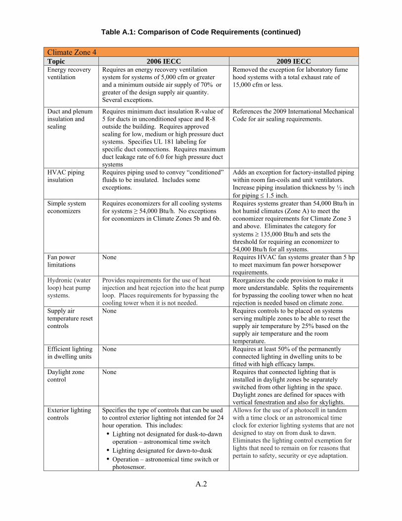
Climate Zone 4 Topic 2006 IECC 2009 IECC Energy recovery ventilation
Requires an energy recovery ventilation system for systems of 5,000 cfm or greater and a minimum outside air supply of 70% or greater of the design supply air quantity. Several exceptions.
Removed the exception for laboratory fume hood systems with a total exhaust rate of 15,000 cfm or less.
Duct and plenum insulation and sealing
Requires minimum duct insulation R-value of 5 for ducts in unconditioned space and R-8 outside the building. Requires approved sealing for low, medium or high pressure duct systems. Specifies UL 181 labeling for specific duct connections. Requires maximum duct leakage rate of 6.0 for high pressure duct systems
References the 2009 International Mechanical Code for air sealing requirements.
HVAC piping insulation
Requires piping used to convey “conditioned” fluids to be insulated. Includes some exceptions.
Adds an exception for factory-installed piping within room fan-coils and unit ventilators. Increase piping insulation thickness by ½ inch for piping ≤ 1.5 inch.
Simple system economizers
Requires economizers for all cooling systems for systems ≥ 54,000 Btu/h. No exceptions for economizers in Climate Zones 5b and 6b.
Requires systems greater than 54,000 Btu/h in hot humid climates (Zone A) to meet the economizer requirements for Climate Zone 3 and above. Eliminates the category for systems ≥ 135,000 Btu/h and sets the threshold for requiring an economizer to 54,000 Btu/h for all systems.
Fan power limitations
None Requires HVAC fan systems greater than 5 hp to meet maximum fan power horsepower requirements.
Hydronic (water loop) heat pump systems.
Provides requirements for the use of heat injection and heat rejection into the heat pump loop. Places requirements for bypassing the cooling tower when it is not needed.
Reorganizes the code provision to make it more understandable. Splits the requirements for bypassing the cooling tower when no heat rejection is needed based on climate zone.
Supply air temperature reset controls
None Requires controls to be placed on systems serving multiple zones to be able to reset the supply air temperature by 25% based on the supply air temperature and the room temperature.
Efficient lighting in dwelling units
None Requires at least 50% of the permanently connected lighting in dwelling units to be fitted with high efficacy lamps.
Daylight zone control
None Requires that connected lighting that is installed in daylight zones be separately switched from other lighting in the space. Daylight zones are defined for spaces with vertical fenestration and also for skylights.
Exterior lighting controls
Specifies the type of controls that can be used to control exterior lighting not intended for 24 hour operation. This includes: • Lighting not designated for dusk-to-dawn
operation – astronomical time switch • Lighting designated for dawn-to-dusk • Operation – astronomical time switch or
photosensor.
Allows for the use of a photocell in tandem with a time clock or an astronomical time clock for exterior lighting systems that are not designed to stay on from dusk to dawn. Eliminates the lighting control exemption for lights that need to remain on for reasons that pertain to safety, security or eye adaptation.
Table A.1: Comparison of Code Requirements (continued)
A.2
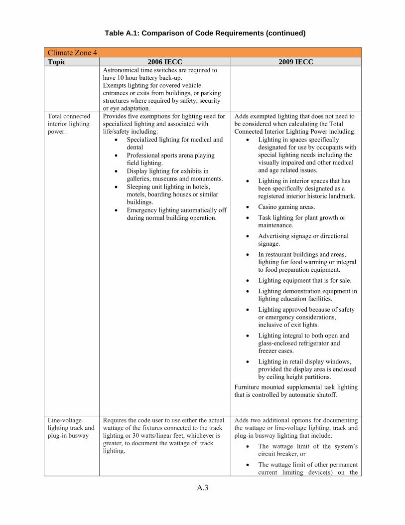
Climate Zone 4 Topic 2006 IECC 2009 IECC
Astronomical time switches are required to have 10 hour battery back-up. Exempts lighting for covered vehicle entrances or exits from buildings, or parking structures where required by safety, security or eye adaptation.
Total connected interior lighting power.
Provides five exemptions for lighting used for specialized lighting and associated with life/safety including:
• Specialized lighting for medical and dental
• Professional sports arena playing field lighting.
• Display lighting for exhibits in galleries, museums and monuments.
• Sleeping unit lighting in hotels, motels, boarding houses or similar buildings.
• Emergency lighting automatically off during normal building operation.
Adds exempted lighting that does not need to be considered when calculating the Total Connected Interior Lighting Power including:
• Lighting in spaces specifically designated for use by occupants with special lighting needs including the visually impaired and other medical and age related issues.
• Lighting in interior spaces that has been specifically designated as a registered interior historic landmark.
• Casino gaming areas. • Task lighting for plant growth or
maintenance. • Advertising signage or directional
signage. • In restaurant buildings and areas,
lighting for food warming or integral to food preparation equipment.
• Lighting equipment that is for sale. • Lighting demonstration equipment in
lighting education facilities. • Lighting approved because of safety
or emergency considerations, inclusive of exit lights.
• Lighting integral to both open and glass-enclosed refrigerator and freezer cases.
• Lighting in retail display windows, provided the display area is enclosed by ceiling height partitions.
Furniture mounted supplemental task lighting that is controlled by automatic shutoff.
Line-voltage lighting track and plug-in busway
Requires the code user to use either the actual wattage of the fixtures connected to the track lighting or 30 watts/linear feet, whichever is greater, to document the wattage of track lighting.
Adds two additional options for documenting the wattage or line-voltage lighting, track and plug-in busway lighting that include:
• The wattage limit of the system’s circuit breaker, or
• The wattage limit of other permanent current limiting device(s) on the
Table A.1: Comparison of Code Requirements (continued)
A.3
A.4
Table A.1: Comparison of Code Requirements (continued)
Climate Zone 4 Topic 2006 IECC 2009 IECC
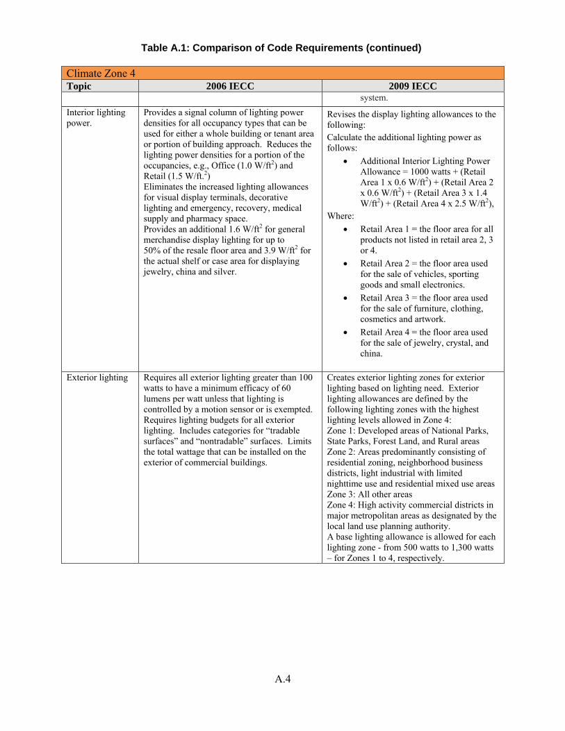
system. Interior lighting power.
Provides a signal column of lighting power densities for all occupancy types that can be used for either a whole building or tenant area or portion of building approach. Reduces the lighting power densities for a portion of the occupancies, e.g., Office (1.0 W/ft2) and Retail (1.5 W/ft.2) Eliminates the increased lighting allowances for visual display terminals, decorative lighting and emergency, recovery, medical supply and pharmacy space. Provides an additional 1.6 W/ft2 for general merchandise display lighting for up to 50% of the resale floor area and 3.9 W/ft2 for the actual shelf or case area for displaying jewelry, china and silver.
Revises the display lighting allowances to the following: Calculate the additional lighting power as follows:
• Additional Interior Lighting Power Allowance = 1000 watts + (Retail Area 1 x 0.6 W/ft2) + (Retail Area 2 x 0.6 W/ft2) + (Retail Area 3 x 1.4 W/ft2) + (Retail Area 4 x 2.5 W/ft2),
Where: • Retail Area 1 = the floor area for all
products not listed in retail area 2, 3 or 4.
• Retail Area 2 = the floor area used for the sale of vehicles, sporting goods and small electronics.
• Retail Area 3 = the floor area used for the sale of furniture, clothing, cosmetics and artwork.
• Retail Area 4 = the floor area used for the sale of jewelry, crystal, and china.
Exterior lighting Requires all exterior lighting greater than 100 watts to have a minimum efficacy of 60 lumens per watt unless that lighting is controlled by a motion sensor or is exempted. Requires lighting budgets for all exterior lighting. Includes categories for “tradable surfaces” and “nontradable” surfaces. Limits the total wattage that can be installed on the exterior of commercial buildings.
Creates exterior lighting zones for exterior lighting based on lighting need. Exterior lighting allowances are defined by the following lighting zones with the highest lighting levels allowed in Zone 4: Zone 1: Developed areas of National Parks, State Parks, Forest Land, and Rural areas Zone 2: Areas predominantly consisting of residential zoning, neighborhood business districts, light industrial with limited nighttime use and residential mixed use areas Zone 3: All other areas Zone 4: High activity commercial districts in major metropolitan areas as designated by the local land use planning authority. A base lighting allowance is allowed for each lighting zone - from 500 watts to 1,300 watts – for Zones 1 to 4, respectively.
Appendix B
Prototype Building Descriptions

Appendix B – Prototype Building Descriptions
Table B.1: Residential Prototype Building Characteristics
Multifamily Building Characteristics General
Building Type Mid-rise Apartment
Total Floor Area 33,700 sqft
Building Shape Rectangle (152 ft x 55.5 ft) Aspect Ratio 2.74 Number of Floors 4 Window Fraction 15 % Window Shading None
Thermal Zoning
Ground floor: 7 apartments and 1 lobby with equivalent apartment area Floors above: 8 apartments with corridor in center Zone depth is 25 ft for each apartment from side walls and each apt is 25ft x 38ft (950 ft²).
Floor to Floor Height (feet) 10 ft Floor to Ceiling Height (feet) 10 ft (no drop down ceiling modeled) Glazing Sill Height (feet) 3 ft. (14 ft wide x 4 ft high) Exterior Walls Steel-framed wall Roof Insulation entirely above deck, metal deck roof Foundation 8 in. concrete slab-on-grade floors (unheated)
Interior Partitions 2 x 4 uninsulated stud wall Internal Mass 6 in. standard wood (16.6 lb/ft²)
Infiltration Peak: 0.2016 cfm/sf of above-grade exterior wall surface area (when fans turn off) Off Peak: 25% of peak infiltration rate (when fans turn on)
Internal Loads & Schedules
Lighting Power Density (W/ft2) Apartment units: 0.36 W/ft² Corridor: 0.5 W/ft² Office: 1.1 W/ft²
Plug Load Power Density (W/ft2) Building average, 0.62 W/ft² Occupancy 78 Total (2.5 person per apartment unit)
B.1
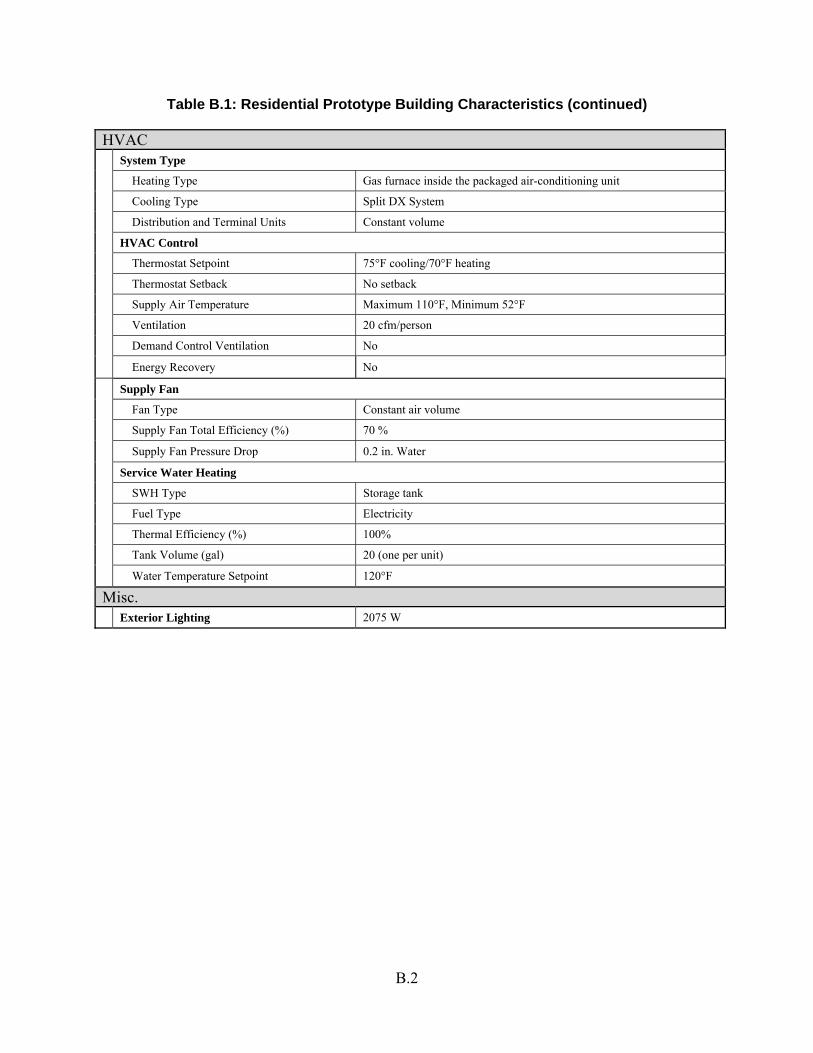
Table B.1: Residential Prototype Building Characteristics (continued)
HVAC System Type Heating Type Gas furnace inside the packaged air-conditioning unit Cooling Type Split DX System Distribution and Terminal Units Constant volume HVAC Control Thermostat Setpoint 75°F cooling/70°F heating
Thermostat Setback No setback
Supply Air Temperature Maximum 110°F, Minimum 52°F Ventilation 20 cfm/person
Demand Control Ventilation No
Energy Recovery No
Supply Fan Fan Type Constant air volume Supply Fan Total Efficiency (%) 70 % Supply Fan Pressure Drop 0.2 in. Water Service Water Heating SWH Type Storage tank Fuel Type Electricity Thermal Efficiency (%) 100% Tank Volume (gal) 20 (one per unit) Water Temperature Setpoint 120°F
Misc. Exterior Lighting 2075 W
B.2
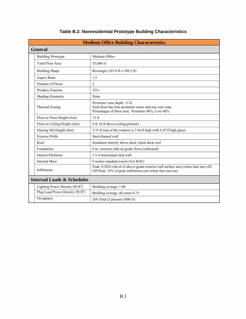
Table B.2: Nonresidential Prototype Building Characteristics
Medium Office Building Characteristics
General Building Prototype Medium Office
Total Floor Area 53,600 sf
Building Shape Rectangle (163.8 ft x 109.2 ft)
Aspect Ratio 1.5 Number of Floors 3 Window Fraction 33% Shading Geometry None
Thermal Zoning Perimeter zone depth: 15 ft. Each floor has four perimeter zones and one core zone. Percentages of floor area: Perimeter 40%, Core 60%
Floor to Floor Height (feet) 13 ft Floor to Ceiling Height (feet) 9 ft, (4 ft above-ceiling plenum) Glazing Sill Height (feet) 3.35 ft (top of the window is 7.64 ft high with 4.29 ft high glass) Exterior Walls Steel-framed wall Roof Insulation entirely above deck, metal deck roof Foundation 8 in. concrete slab-on-grade floors (unheated) Interior Partitions 2 x 4 uninsulated stud wall Internal Mass 6 inches standard wood (16.6 lb/ft²)
Infiltration Peak: 0.2016 cfm/sf of above-grade exterior wall surface area (when fans turn off) Off Peak: 25% of peak infiltration rate (when fans turn on)
Internal Loads & Schedules Lighting Power Density (W/ft2) Building average, 1.00 Plug Load Power Density (W/ft2) Building average, all zones 0.75 Occupancy 268 Total (5 persons/1000 sf)
B.3
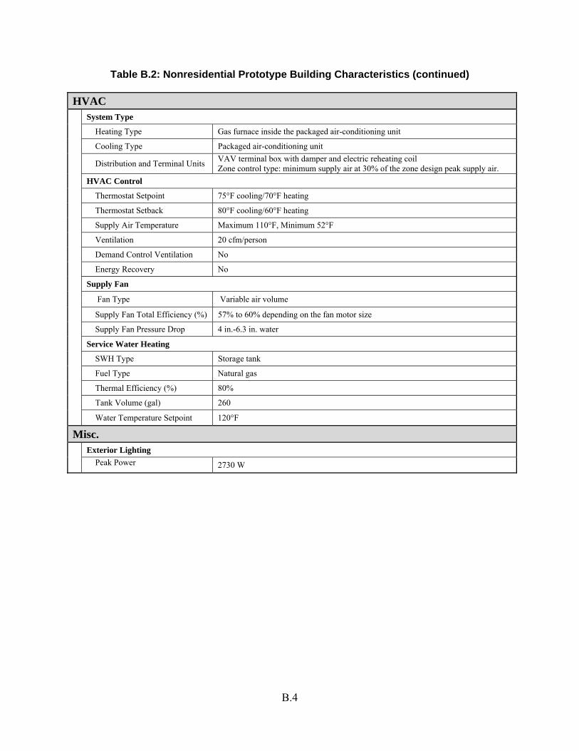
Table B.2: Nonresidential Prototype Building Characteristics (continued)
HVAC System Type Heating Type Gas furnace inside the packaged air-conditioning unit Cooling Type Packaged air-conditioning unit Distribution and Terminal Units VAV terminal box with damper and electric reheating coil
Zone control type: minimum supply air at 30% of the zone design peak supply air. HVAC Control Thermostat Setpoint 75°F cooling/70°F heating Thermostat Setback 80°F cooling/60°F heating Supply Air Temperature Maximum 110°F, Minimum 52°F Ventilation 20 cfm/person Demand Control Ventilation No Energy Recovery No Supply Fan
Fan Type Variable air volume
Supply Fan Total Efficiency (%) 57% to 60% depending on the fan motor size Supply Fan Pressure Drop 4 in.-6.3 in. water Service Water Heating SWH Type Storage tank Fuel Type Natural gas Thermal Efficiency (%) 80% Tank Volume (gal) 260 Water Temperature Setpoint 120°F
Misc. Exterior Lighting Peak Power 2730 W
B.4
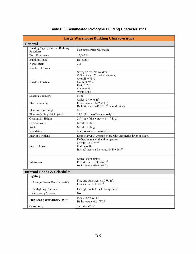
Table B.3: Semiheated Prototype Building Characteristics
Large Warehouse Building Characteristics
General Building Type (Principal Building
Function) Non-refrigerated warehouse
Total Floor Area 52,045 ft2 Building Shape Rectangle Aspect Ratio 2.2 Number of Floors 1
Window Fraction
Storage Area: No windows; Office Area: 12% veiw windows; Overall: 0.71%; North: 0.76%; East: 0.0%; South: 0.0%; West: 2.86%
Shading Geometry None
Thermal Zoning Office: 2549.76 ft2 Fine Storage: 14,998.54 ft2 Bulk Storage: 34496.61 ft2 (semi-heated)
Floor to Floor Height 28 ft Floor to Ceiling Height (feet) 14 ft (for the office area only) Glazing Sill Height 3 ft (top of the window is 8-ft high) Exterior Walls Metal Building Roof Metal Building Foundation 6 in. concrete slab-on-grade Interior Partitions Double layer of gypsum board with an exterior layer of stucco
Internal Mass
Defined as material with properties: density: 12.5 lb/ ft2 thickness: 8 ft Internal mass surface area: 64889.66 ft2
Infiltration Office: 0.078cfm/ft2 Fine storage: 0.080 cfm/ft2 Bulk storage: 4793.56 cfm
Internal Loads & Schedules Lighting
Average Power Density (W/ft2) Fine and bulk area: 0.80 W/ ft2; Office area: 1.00 W/ ft2
Daylighting Controls Daylight control: bulk storage area Occupancy Sensors No
Plug Load power density (W/ft2) Office: 0.75 W/ ft2 Bulk storage: 0.24 W/ ft2
Occupancy 5 (in the office)
B.5
B.6
Table B.3: Semi-heated Prototype Building Characteristics (continued)
HVAC System Type Heating Type Gas-fired furnace Cooling Type DX cooling coil Distribution and Terminal Units Direct uncontrolled air HVAC Control
Thermostat Setpoint Fine storage: 80°F cooling/ 60°F heating; Office area: 75°F cooling/ 70°F heating; Bulk storage: 50°F heating;
Thermostat Setback Office Area: 85°F Cooling/60°F Heating
Supply Air Temperature Maximum 110°F, Minimum 55°F
Ventilation Bulk storage: 80009 cfm (exhaust); 2000 cfm (natural) Office: 0.085 cfm/ft2 Storage: 0.06 cfm/ft2
Demand Control Ventilation No Energy Recovery No Supply Fan Fan Type Constant air volume
Supply Fan Total Efficiency (%) Office area: fan efficiency 54.6%, motor efficiency 84%; Fine storage: fan efficiency 56.875%, motor efficiency 87.5; Bulk storage unit heater: fan efficiency 53.6%, motor efficiency 82.5%
Supply Fan Pressure Drop Office area: 2.5 in. water Fine storage: 2.5 in. water Bulk storage: 0.2 in. water
Service Water Heating SWH Type Electric storage water heater Fuel Type Electricity Thermal Efficiency (%) 100% Tank Volume (gal) 20 Water Temperature Setpoint 120°F
Misc. Exterior Lighting Peak Power 4800 watts