Embed Size (px)
Citation preview
Foxconn Interconnect Technology Proprietary & Confidential 1
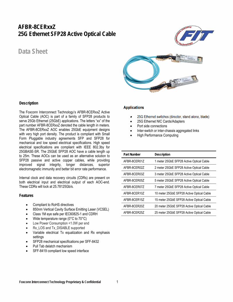
Description The Foxconn Interconnect Technology’s AFBR-8CERxxZ Active Optical Cable (AOC) is part of a family of SFP28 products to serve 25Gb Ethernet (25GbE) applications. The letters “xx” of the part number AFBR-8CERxxZ denoted the cable length in meters. The AFBR-8CERxxZ AOC enables 25GbE equipment designs with very high port density. The product is compliant with Small Form Pluggable industry agreements SFP and SFP28 for mechanical and low speed electrical specifications. High speed electrical specifications are compliant with IEEE 802.3by for 25GBASE-SR. The 25GbE SFP28 AOC have a cable length up to 25m. These AOCs can be used as an alternative solution to SFP28 passive and active copper cables, while providing improved signal integrity, longer distances, superior electromagnetic immunity and better bit error rate performance. Internal clock and data recovery circuits (CDRs) are present on both electrical input and electrical output of each AOC-end. These CDRs will lock at 25.78125Gb/s. Features
Compliant to RoHS directives 850nm Vertical Cavity Surface Emitting Laser (VCSEL) Class 1M eye safe per IEC60825-1 and CDRH Wide temperature range (0°C to 70°C) Low Power Consumption <1.0W per end Rx_LOS and Tx_DISABLE supported Variable electrical Tx equalization and Rx emphasis
settings SFP28 mechanical specifications per SFF-8432 Pull Tab delatch mechanism SFF-8419 compliant low speed interface
Applications
25G Ethernet switches (director, stand alone, blade) 25G Ethernet NIC Cards/Adapters Port side connections Inter-switch or inter-chassis aggregated links High Performance Computing
Part Number Description
AFBR-8CER01Z 1 meter 25GbE SFP28 Active Optical Cable
AFBR-8CER02Z 2 meter 25GbE SFP28 Active Optical Cable
AFBR-8CER03Z 3 meter 25GbE SFP28 Active Optical Cable
AFBR-8CER05Z 5 meter 25GbE SFP28 Active Optical Cable
AFBR-8CER07Z 7 meter 25GbE SFP28 Active Optical Cable
AFBR-8CER10Z 10 meter 25GbE SFP28 Active Optical Cable
AFBR-8CER15Z 15 meter 25GbE SFP28 Active Optical Cable
AFBR-8CER20Z 20 meter 25GbE SFP28 Active Optical Cable
AFBR-8CER25Z 25 meter 25GbE SFP28 Active Optical Cable
AFBR-8CERxxZ 25G Ethernet SFP28 Active Optical Cable
Data Sheet
Foxconn Interconnect Technology Proprietary & Confidential 2
Installation The AFBR-8CERxxZ Active Optical Cable package is com-pliant with the SFF-8432 Improved Pluggable Form factor housing specification for the SFP28. The AFBR-8CERxxZ is hot-pluggable, allowing both active cable ends to be installed while the host system is operating and on-line. Upon insertion, the housing makes initial contact with the host board SFP cage, mitigating potential damage due to Electro-Static Discharge (ESD).
Digital Interface and Serial Identification The two-wire interface protocol and signalling detail are based on SFF-8419. Conventional EEPROM memory, bytes 0-255 at 2 wire serial interface (I2C) 8 bit address 1010000X (A0h), is organized in compliance with SFF-8472.
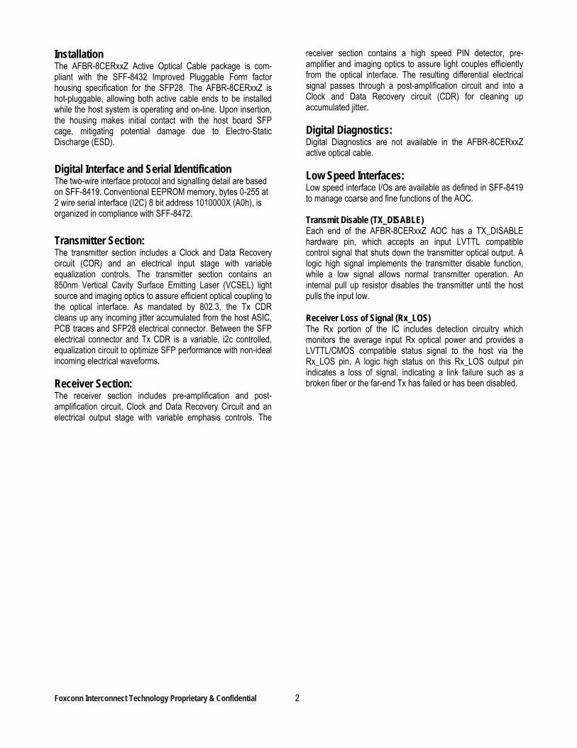
Transmitter Section: The transmitter section includes a Clock and Data Recovery circuit (CDR) and an electrical input stage with variable equalization controls. The transmitter section contains an 850nm Vertical Cavity Surface Emitting Laser (VCSEL) light source and imaging optics to assure efficient optical coupling to the optical interface. As mandated by 802.3, the Tx CDR cleans up any incoming jitter accumulated from the host ASIC, PCB traces and SFP28 electrical connector. Between the SFP electrical connector and Tx CDR is a variable, i2c controlled, equalization circuit to optimize SFP performance with non-ideal incoming electrical waveforms. Receiver Section: The receiver section includes pre-amplification and post-amplification circuit, Clock and Data Recovery Circuit and an electrical output stage with variable emphasis controls. The
receiver section contains a high speed PIN detector, pre-amplifier and imaging optics to assure light couples efficiently from the optical interface. The resulting differential electrical signal passes through a post-amplification circuit and into a Clock and Data Recovery circuit (CDR) for cleaning up accumulated jitter. Digital Diagnostics: Digital Diagnostics are not available in the AFBR-8CERxxZ active optical cable. Low Speed Interfaces: Low speed interface I/Os are available as defined in SFF-8419 to manage coarse and fine functions of the AOC. Transmit Disable (TX_DISABLE) Each end of the AFBR-8CERxxZ AOC has a TX_DISABLE hardware pin, which accepts an input LVTTL compatible control signal that shuts down the transmitter optical output. A logic high signal implements the transmitter disable function, while a low signal allows normal transmitter operation. An internal pull up resistor disables the transmitter until the host pulls the input low. Receiver Loss of Signal (Rx_LOS) The Rx portion of the IC includes detection circuitry which monitors the average input Rx optical power and provides a LVTTL/CMOS compatible status signal to the host via the Rx_LOS pin. A logic high status on this Rx_LOS output pin indicates a loss of signal, indicating a link failure such as a broken fiber or the far-end Tx has failed or has been disabled.
Foxconn Interconnect Technology Proprietary & Confidential 3
Figure 1: Block Diagram
Foxconn Interconnect Technology Proprietary & Confidential 4
Application Support An Evaluation Kit and Reference Designs are available to assist in evaluation of the AFBR-8CERxxZ. Please contact your local Field Sales representative for availability and ordering details. Ordering Information Please contact your local field sales engineer or Foxconn Interconnect Technology’s distributors for ordering information. Caution There are no user serviceable parts or maintenance requirements for the AFBR-8CERxxZ. All mechanical adjustments are made at the factory prior to shipment. Tampering with, modifying, misusing or improperly handling the AFBR-8CERxxZ will void the product warranty. It may also result in improper operation and possibly overstress the device. Performance degradation or device failure may result. Operating above maximum operating conditions or in a manner inconsistent with its design and function may result in exposure to hazardous light radiation and may constitute an act of modifying or manufacturing a laser product. Persons performing such an act are required by law to recertify and re-identify the laser product under the provisions of U.S. 21 CFR (Subchapter J) and TUV. Customer Manufacturing Processes This AOC is pluggable and is not designed for aqueous wash, IR reflow, or wave soldering processes. Regulatory Compliance The AFBR-8CERxxZ complies with all applicable laws and regulations as detailed in Table 1. Certification level is dependent on the overall configuration of the host equipment. Electrostatic Discharge (ESD) The AFBR-8CERxxZ is compatible with ESD levels found in typical manufacturing and operating environments as described in Table 1. In the normal handling and operation of optical cables, ESD is of concern in two circumstances. The first case is during handling of the AOC prior to insertion
into an SFP28 compliant cage. To protect the device, it is important to use normal ESD handling pre-cautions. These include use of grounded wrist straps, work-benches and floor wherever an optical cable is handled. The second case to consider is static discharges to the exterior of the host equipment chassis after installation. If the optical interface is exposed to the exterior of host equipment cabinet, the optical cable may be subject to system level ESD requirements. Electromagnetic Interference (EMI) Equipment incorporating 25 gigabit transceivers or active optical cables is typically subject to regulation by the FCC in the United States, CENELEC EN55022 (CISPR 22) in Europe and VCCI in Japan. The AFBR-8CERxxZ enables equipment compliance to these standards detailed in Table 1. The metal housing and shielded design of the AFBR-8CERxxZ minimizes the EMI challenge facing the equipment designer. For superior EMI performance it is recommended that equipment designs utilize SFP+ cages per SFF 8432. RF Immunity (Susceptibility) The EMI immunity of the AFBR-8CERxxZ exceeds typical industry standards. Eye Safety The AFBR-8CERxxZ provides Class 1M (single fault tolerant) eye safety by design and has been tested for compliance with the requirements listed in Table 1. The eye safety circuit continuously monitors the optical output power level and will disable the transmitter upon detecting a condition beyond the scope of Class 1M certification. Such conditions can be due to inputs from the host board (Vcc fluctuation, unbalanced code) or a fault within the AOC. US CDRH and EU TUV certificates are listed in table 1. Flammability The AFBR-8CERxxZ optical cable is made of metal and high strength, heat resistant, chemical resistant and UL 94V-0 flame retardant plastic.
Foxconn Interconnect Technology Proprietary & Confidential 5
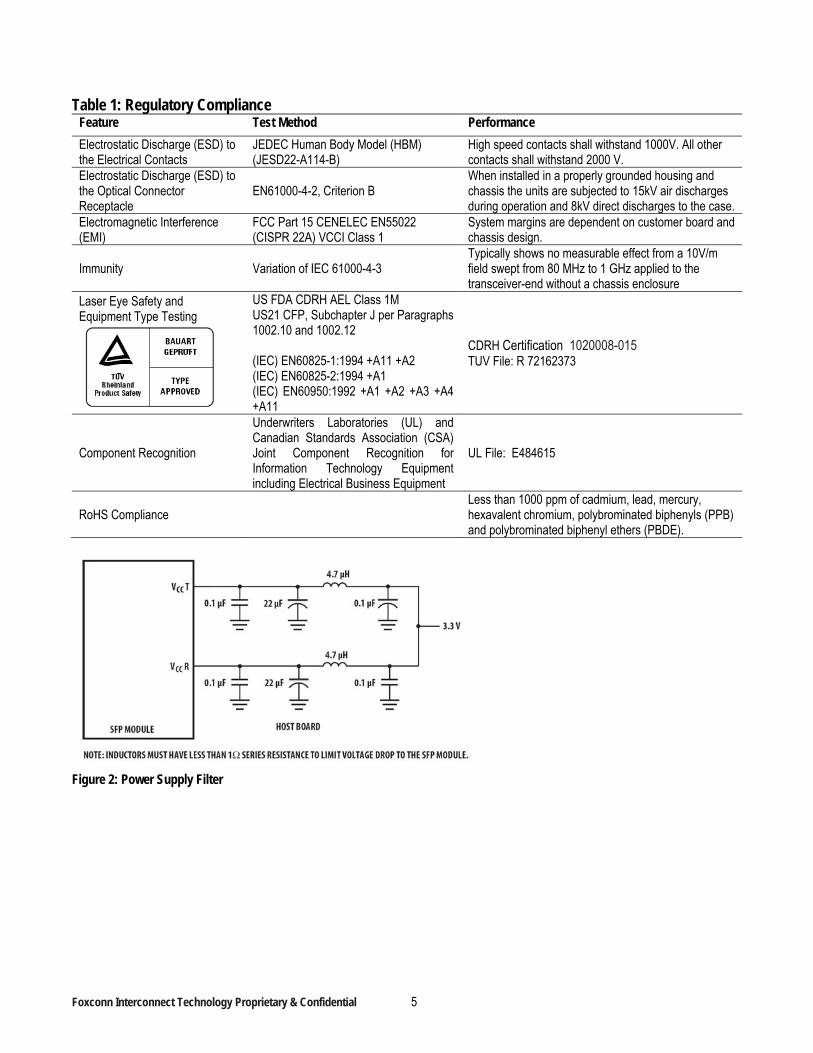
Table 1: Regulatory Compliance Feature Test Method Performance
Electrostatic Discharge (ESD) to the Electrical Contacts
JEDEC Human Body Model (HBM) (JESD22-A114-B)
High speed contacts shall withstand 1000V. All other contacts shall withstand 2000 V.
Electrostatic Discharge (ESD) to the Optical Connector Receptacle
EN61000-4-2, Criterion B When installed in a properly grounded housing and chassis the units are subjected to 15kV air discharges during operation and 8kV direct discharges to the case.
Electromagnetic Interference (EMI)
FCC Part 15 CENELEC EN55022 (CISPR 22A) VCCI Class 1
System margins are dependent on customer board and chassis design.
Immunity Variation of IEC 61000-4-3 Typically shows no measurable effect from a 10V/m field swept from 80 MHz to 1 GHz applied to the transceiver-end without a chassis enclosure
Laser Eye Safety and Equipment Type Testing
US FDA CDRH AEL Class 1M US21 CFP, Subchapter J per Paragraphs 1002.10 and 1002.12 (IEC) EN60825-1:1994 +A11 +A2 (IEC) EN60825-2:1994 +A1 (IEC) EN60950:1992 +A1 +A2 +A3 +A4 +A11
CDRH Certification 1020008-015 TUV File: R 72162373
Component Recognition
Underwriters Laboratories (UL) and Canadian Standards Association (CSA) Joint Component Recognition for Information Technology Equipment including Electrical Business Equipment
UL File: E484615
RoHS Compliance Less than 1000 ppm of cadmium, lead, mercury, hexavalent chromium, polybrominated biphenyls (PPB) and polybrominated biphenyl ethers (PBDE).
Figure 2: Power Supply Filter
Foxconn Interconnect Technology Proprietary & Confidential 6
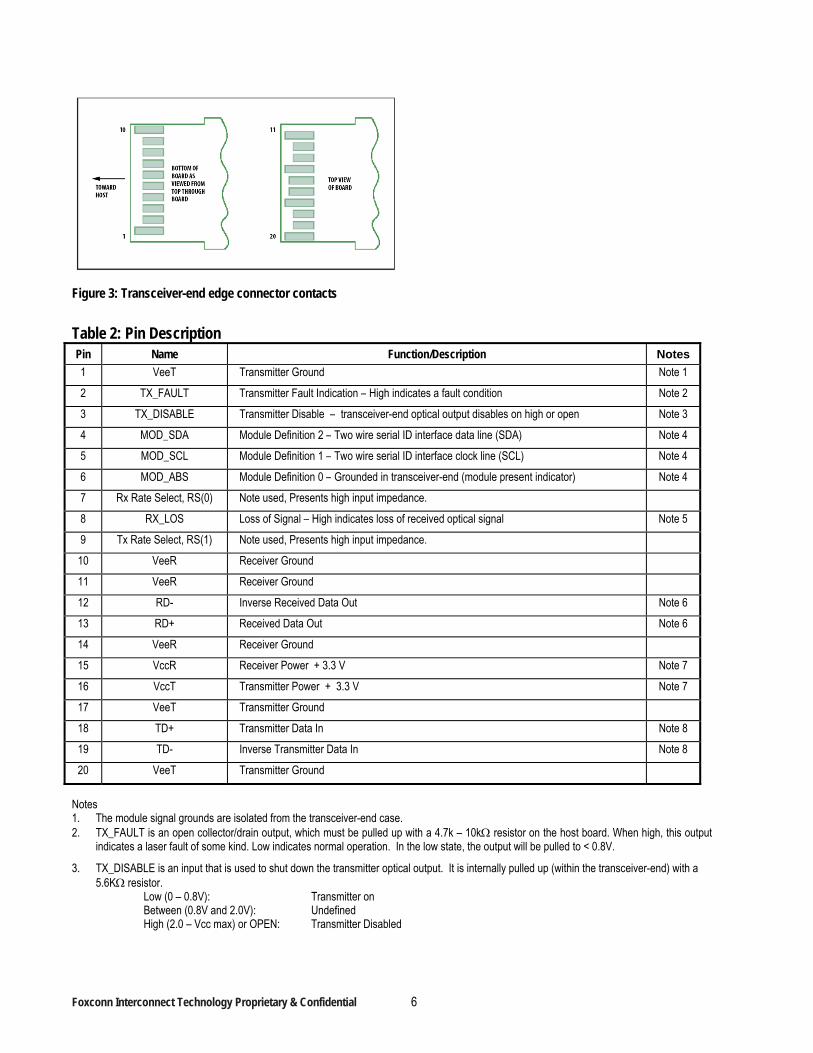
Figure 3: Transceiver-end edge connector contacts
Table 2: Pin Description Pin Name Function/Description Notes
1 VeeT Transmitter Ground Note 1
2 TX_FAULT Transmitter Fault Indication – High indicates a fault condition Note 2
3 TX_DISABLE Transmitter Disable – transceiver-end optical output disables on high or open Note 3
4 MOD_SDA Module Definition 2 – Two wire serial ID interface data line (SDA) Note 4
5 MOD_SCL Module Definition 1 – Two wire serial ID interface clock line (SCL) Note 4
6 MOD_ABS Module Definition 0 – Grounded in transceiver-end (module present indicator) Note 4
7 Rx Rate Select, RS(0) Note used, Presents high input impedance.
8 RX_LOS Loss of Signal – High indicates loss of received optical signal Note 5
9 Tx Rate Select, RS(1) Note used, Presents high input impedance.
10 VeeR Receiver Ground
11 VeeR Receiver Ground
12 RD- Inverse Received Data Out Note 6
13 RD+ Received Data Out Note 6
14 VeeR Receiver Ground
15 VccR Receiver Power + 3.3 V Note 7
16 VccT Transmitter Power + 3.3 V Note 7
17 VeeT Transmitter Ground
18 TD+ Transmitter Data In Note 8
19 TD- Inverse Transmitter Data In Note 8
20 VeeT Transmitter Ground
Notes 1. The module signal grounds are isolated from the transceiver-end case. 2. TX_FAULT is an open collector/drain output, which must be pulled up with a 4.7k – 10k resistor on the host board. When high, this output
indicates a laser fault of some kind. Low indicates normal operation. In the low state, the output will be pulled to < 0.8V.
3. TX_DISABLE is an input that is used to shut down the transmitter optical output. It is internally pulled up (within the transceiver-end) with a 5.6K resistor.
Low (0 – 0.8V): Transmitter on Between (0.8V and 2.0V): Undefined High (2.0 – Vcc max) or OPEN: Transmitter Disabled
Foxconn Interconnect Technology Proprietary & Confidential 7
4. The signals Mod-Def 0, 1, 2 designate the two wire serial interface pins. They must be pulled up with a 4.7k – 10k resistor on the host board.
Mod_ABS is grounded by the module to indicate the module is present Mod_SCL is serial clock line (SCL) of two wire serial interface Mod_SDA is serial data line (SDA) of two wire serial interface
5. RX_LOS (Rx Loss of Signal) is an open collector/drain output that must be pulled up with a 4.7k – 10k resistor on the host board. When high, this output indicates the received optical power is below the worst case receiver sensitivity (as defined by the standard in use). Low indicates normal operation. In the low state, the output will be pulled to < 0.8V.
6. RD-/+ designate the differential receiver outputs. They are AC coupled 100 differential lines which should be terminated with 100 differential at the host SERDES input. AC coupling is done inside the transceiver-end and is not required on the host board. The voltage swing on these lines will be between 50 and 900 mV differential (25 – 450 mV single ended) when properly terminated.
7. VccR and VccT are the receiver and transmitter power supplies. They are defined at the SFP28 connector pin.
8. TD-/+ designate the differential transmitter inputs. They are AC coupled differential lines with 100 differential termination inside the transceiver-end. The AC coupling is done inside the transceiver-end and is not required on the host board. The inputs will accept differential swings up to 900 mV differential with at least 95mV inner eye height after reference CTLE.
Foxconn Interconnect Technology Proprietary & Confidential 8
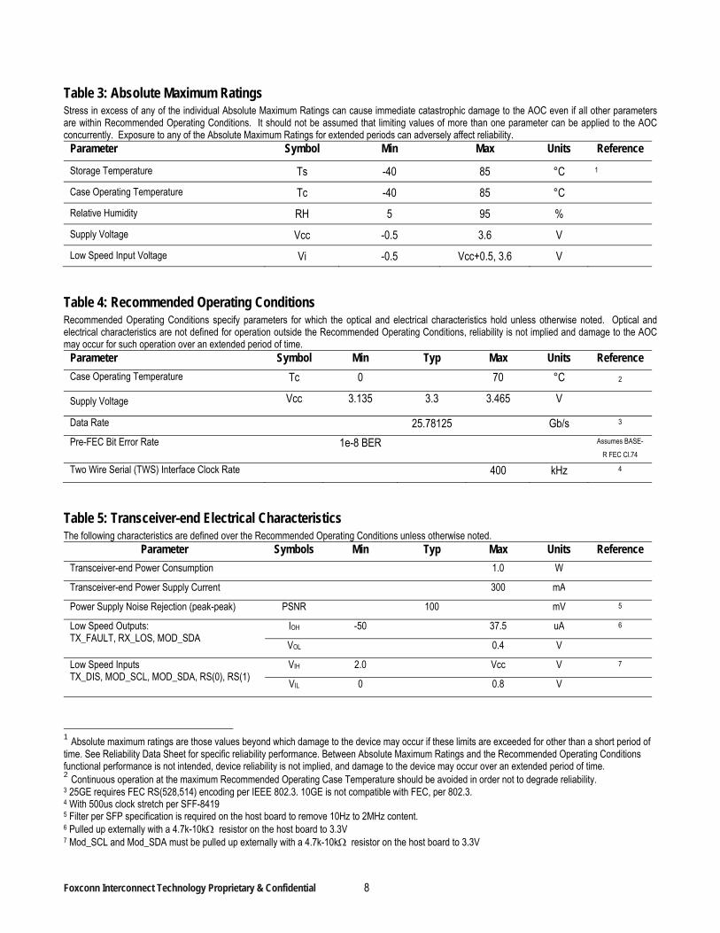
Table 3: Absolute Maximum Ratings Stress in excess of any of the individual Absolute Maximum Ratings can cause immediate catastrophic damage to the AOC even if all other parameters are within Recommended Operating Conditions. It should not be assumed that limiting values of more than one parameter can be applied to the AOC concurrently. Exposure to any of the Absolute Maximum Ratings for extended periods can adversely affect reliability.
Parameter Symbol Min Max Units Reference
Storage Temperature Ts -40 85 °C 1
Case Operating Temperature Tc -40 85 °C
Relative Humidity RH 5 95 %
Supply Voltage Vcc -0.5 3.6 V
Low Speed Input Voltage Vi -0.5 Vcc+0.5, 3.6 V
Table 4: Recommended Operating Conditions Recommended Operating Conditions specify parameters for which the optical and electrical characteristics hold unless otherwise noted. Optical and electrical characteristics are not defined for operation outside the Recommended Operating Conditions, reliability is not implied and damage to the AOC may occur for such operation over an extended period of time.
Parameter Symbol Min Typ Max Units Reference
Case Operating Temperature Tc 0 70 °C 2
Supply Voltage Vcc 3.135 3.3 3.465 V
Data Rate 25.78125 Gb/s 3
Pre-FEC Bit Error Rate 1e-8 BER Assumes BASE-
R FEC Cl.74
Two Wire Serial (TWS) Interface Clock Rate 400 kHz 4
Table 5: Transceiver-end Electrical Characteristics The following characteristics are defined over the Recommended Operating Conditions unless otherwise noted.
Parameter Symbols Min Typ Max Units Reference
Transceiver-end Power Consumption 1.0 W
Transceiver-end Power Supply Current 300 mA
Power Supply Noise Rejection (peak-peak) PSNR 100 mV 5
Low Speed Outputs: TX_FAULT, RX_LOS, MOD_SDA
IOH -50 37.5 uA 6
VOL 0.4 V
Low Speed Inputs TX_DIS, MOD_SCL, MOD_SDA, RS(0), RS(1)
VIH 2.0 Vcc V 7
VIL 0 0.8 V
1 Absolute maximum ratings are those values beyond which damage to the device may occur if these limits are exceeded for other than a short period of time. See Reliability Data Sheet for specific reliability performance. Between Absolute Maximum Ratings and the Recommended Operating Conditions functional performance is not intended, device reliability is not implied, and damage to the device may occur over an extended period of time. 2 Continuous operation at the maximum Recommended Operating Case Temperature should be avoided in order not to degrade reliability. 3 25GE requires FEC RS(528,514) encoding per IEEE 802.3. 10GE is not compatible with FEC, per 802.3. 4 With 500us clock stretch per SFF-8419 5 Filter per SFP specification is required on the host board to remove 10Hz to 2MHz content. 6 Pulled up externally with a 4.7k-10k resistor on the host board to 3.3V 7 Mod_SCL and Mod_SDA must be pulled up externally with a 4.7k-10k resistor on the host board to 3.3V
Foxconn Interconnect Technology Proprietary & Confidential 9
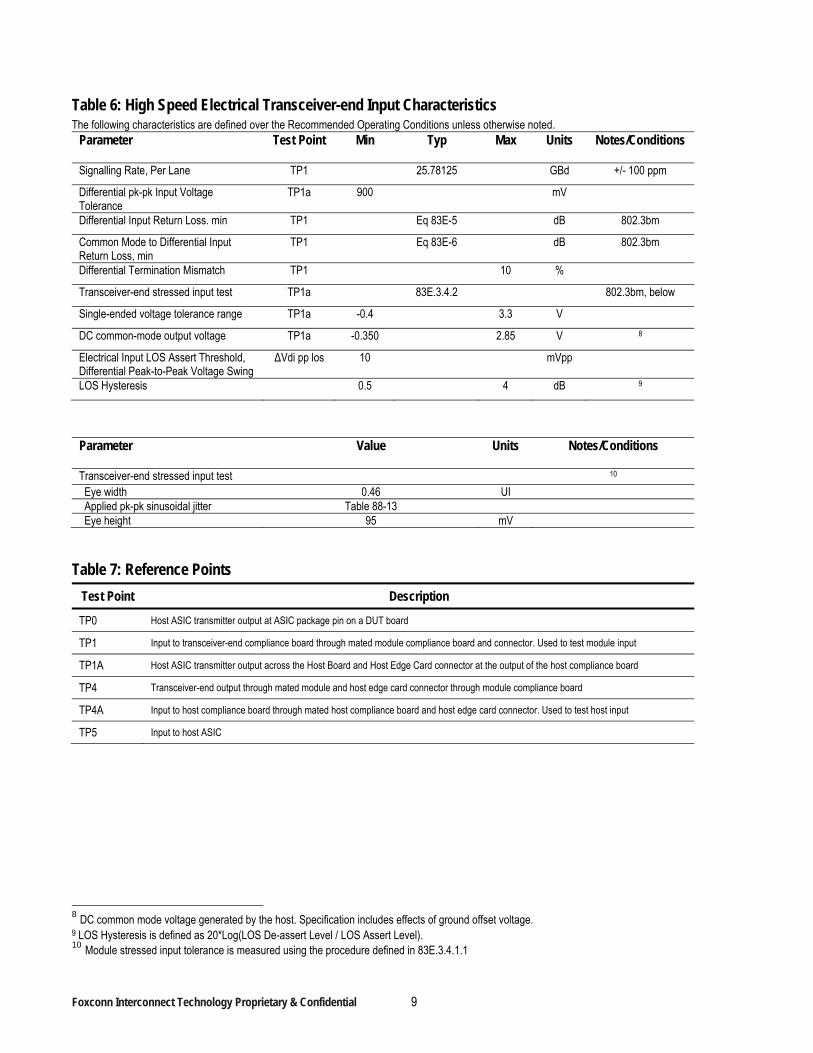
Table 6: High Speed Electrical Transceiver-end Input Characteristics The following characteristics are defined over the Recommended Operating Conditions unless otherwise noted.
Parameter
Test Point Min Typ Max Units Notes/Conditions
Signalling Rate, Per Lane TP1 25.78125 GBd +/- 100 ppm
Differential pk-pk Input Voltage Tolerance
TP1a 900 mV
Differential Input Return Loss. min TP1 Eq 83E-5 dB 802.3bm
Common Mode to Differential Input Return Loss, min
TP1 Eq 83E-6 dB 802.3bm
Differential Termination Mismatch TP1 10 %
Transceiver-end stressed input test TP1a 83E.3.4.2 802.3bm, below
Single-ended voltage tolerance range TP1a -0.4 3.3 V
DC common-mode output voltage TP1a -0.350 2.85 V 8
Electrical Input LOS Assert Threshold, Differential Peak-to-Peak Voltage Swing
ΔVdi pp los 10 mVpp
LOS Hysteresis 0.5 4 dB 9
Parameter
Value Units Notes/Conditions
Transceiver-end stressed input test 10 Eye width 0.46 UI Applied pk-pk sinusoidal jitter Table 88-13 Eye height 95 mV
Table 7: Reference Points
Test Point Description
TP0 Host ASIC transmitter output at ASIC package pin on a DUT board
TP1 Input to transceiver-end compliance board through mated module compliance board and connector. Used to test module input
TP1A Host ASIC transmitter output across the Host Board and Host Edge Card connector at the output of the host compliance board
TP4 Transceiver-end output through mated module and host edge card connector through module compliance board
TP4A Input to host compliance board through mated host compliance board and host edge card connector. Used to test host input
TP5 Input to host ASIC
8 DC common mode voltage generated by the host. Specification includes effects of ground offset voltage. 9 LOS Hysteresis is defined as 20*Log(LOS De-assert Level / LOS Assert Level). 10 Module stressed input tolerance is measured using the procedure defined in 83E.3.4.1.1
Foxconn Interconnect Technology Proprietary & Confidential 10
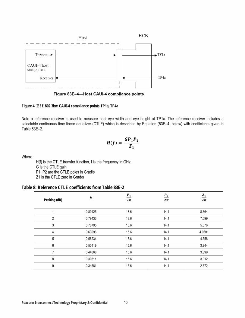
Figure 4: IEEE 802.3bm CAUI-4 compliance points TP1a, TP4a
Note a reference receiver is used to measure host eye width and eye height at TP1a. The reference receiver includes a selectable continuous time linear equalizer (CTLE) which is described by Equation (83E–4, below) with coefficients given in Table 83E–2.
Where
H(f) is the CTLE transfer function, f is the frequency in GHz G is the CTLE gain P1, P2 are the CTLE poles in Grad/s Z1 is the CTLE zero in Grad/s
Table 8: Reference CTLE coefficients from Table 83E-2
Peaking (dB)
1 0.89125 18.6 14.1 8.364
2 0.79433 18.6 14.1 7.099
3 0.70795 15.6 14.1 5.676
4 0.63096 15.6 14.1 4.9601
5 0.56234 15.6 14.1 4.358
6 0.50119 15.6 14.1 3.844
7 0.44668 15.6 14.1 3.399
8 0.39811 15.6 14.1 3.012
9 0.34581 15.6 14.1 2.672
Foxconn Interconnect Technology Proprietary & Confidential 11
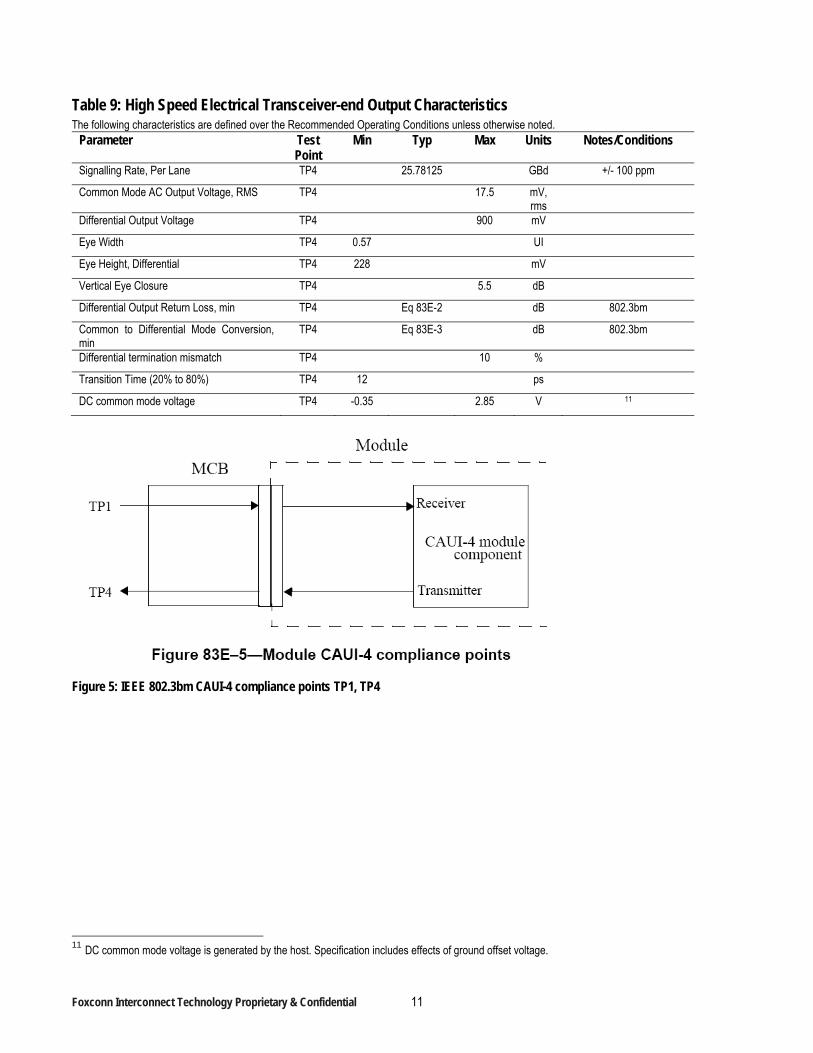
Table 9: High Speed Electrical Transceiver-end Output Characteristics The following characteristics are defined over the Recommended Operating Conditions unless otherwise noted.
Parameter
Test Point
Min Typ Max Units Notes/Conditions
Signalling Rate, Per Lane TP4 25.78125 GBd +/- 100 ppm
Common Mode AC Output Voltage, RMS TP4 17.5 mV, rms
Differential Output Voltage TP4 900 mV
Eye Width TP4 0.57 UI
Eye Height, Differential TP4 228 mV
Vertical Eye Closure TP4 5.5 dB
Differential Output Return Loss, min TP4 Eq 83E-2 dB 802.3bm
Common to Differential Mode Conversion, min
TP4 Eq 83E-3 dB 802.3bm
Differential termination mismatch TP4 10 %
Transition Time (20% to 80%) TP4 12 ps
DC common mode voltage TP4 -0.35 2.85 V 11
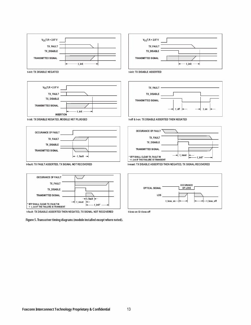
Figure 5: IEEE 802.3bm CAUI-4 compliance points TP1, TP4
11 DC common mode voltage is generated by the host. Specification includes effects of ground offset voltage.
Foxconn Interconnect Technology Proprietary & Confidential 12
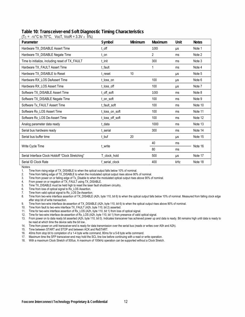
Table 10: Transceiver-end Soft Diagnostic Timing Characteristics (TC = -10°C to 70°C, VccT, VccR = 3.3V 5%) Parameter Symbol Minimum Maximum Unit Notes
Hardware TX_DISABLE Assert Time t_off 100 µs Note 1
Hardware TX_DISABLE Negate Time t_on 2 ms Note 2
Time to initialize, including reset of TX_FAULT t_init 300 ms Note 3
Hardware TX_FAULT Assert Time t_fault 1 ms Note 4
Hardware TX_DISABLE to Reset t_reset 10 µs Note 5
Hardware RX_LOS DeAssert Time t_loss_on 100 µs Note 6
Hardware RX_LOS Assert Time t_loss_off 100 µs Note 7
Software TX_DISABLE Assert Time t_off_soft 100 ms Note 8
Software TX_DISABLE Negate Time t_on_soft 100 ms Note 9
Software Tx_FAULT Assert Time t_fault_soft 100 ms Note 10
Software Rx_LOS Assert Time t_loss_on_soft 100 ms Note 11
Software Rx_LOS De-Assert Time t_loss_off_soft 100 ms Note 12
Analog parameter data ready t_data 1000 ms Note 13
Serial bus hardware ready t_serial 300 ms Note 14
Serial bus buffer time t_buf 20 µs Note 15
Write Cycle Time t_write 40 ms
Note 16 80 ms
Serial Interface Clock Holdoff “Clock Stretching” T_clock_hold 500 µs Note 17
Serial ID Clock Rate f_serial_clock 400 kHz Note 18 Notes 1. Time from rising edge of TX_DISABLE to when the optical output falls below 10% of nominal. 2. Time from falling edge of TX_DISABLE to when the modulated optical output rises above 90% of nominal. 3. Time from power on or falling edge of Tx_Disable to when the modulated optical output rises above 90% of nominal. 4. From power on or negation of TX_FAULT using TX_DISABLE. 5. Time TX_DISABLE must be held high to reset the laser fault shutdown circuitry. 6. Time from loss of optical signal to Rx_LOS Assertion. 7. Time from valid optical signal to Rx_LOS De-Assertion. 8. Time from two-wire interface assertion of TX_DISABLE (A2h, byte 110, bit 6) to when the optical output falls below 10% of nominal. Measured from falling clock edge
after stop bit of write transaction. 9. Time from two-wire interface de-assertion of TX_DISABLE (A2h, byte 110, bit 6) to when the optical output rises above 90% of nominal. 10. Time from fault to two-wire interface TX_FAULT (A2h, byte 110, bit 2) asserted. 11. Time for two-wire interface assertion of Rx_LOS (A2h, byte 110, bit 1) from loss of optical signal. 12. Time for two-wire interface de-assertion of Rx_LOS (A2h, byte 110, bit 1) from presence of valid optical signal. 13. From power on to data ready bit asserted (A2h, byte 110, bit 0). Indicates transceiver has achieved power up and data is ready. Bit remains high until data is ready to
be read at which time the device sets the bit low.. 14. Time from power on until transceiver-end is ready for data transmission over the serial bus (reads or writes over A0h and A2h). 15. Time between START and STOP and between ACK and ReSTART. 16. 40ms from stop bit to completion of a 1-4 byte write command, 80ms for a 5-8 byte write command. 17. Maximum time the SFP transceiver-end may hold the SCL line low before continuing with a read or write operation. 18. With a maximum Clock Stretch of 500us. A maximum of 100kHz operation can be supported without a Clock Stretch.
Foxconn Interconnect Technology Proprietary & Confidential 13
Foxconn Interconnect Technology Proprietary & Confidential 14
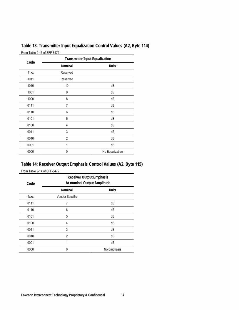
Table 13: Transmitter Input Equalization Control Values (A2, Byte 114) From Table 9-13 of SFF-8472
Code Transmitter Input Equalization
Nominal Units
11xx Reserved
1011 Reserved
1010 10 dB
1001 9 dB
1000 8 dB
0111 7 dB
0110 6 dB
0101 5 dB
0100 4 dB
0011 3 dB
0010 2 dB
0001 1 dB
0000 0 No Equalization
Table 14: Receiver Output Emphasis Control Values (A2, Byte 115) From Table 9-14 of SFF-8472
Code
Receiver Output Emphasis
At nominal Output Amplitude
Nominal Units
1xxx Vendor Specific
0111 7 dB
0110 6 dB
0101 5 dB
0100 4 dB
0011 3 dB
0010 2 dB
0001 1 dB
0000 0 No Emphasis
Foxconn Interconnect Technology Proprietary & Confidential 15
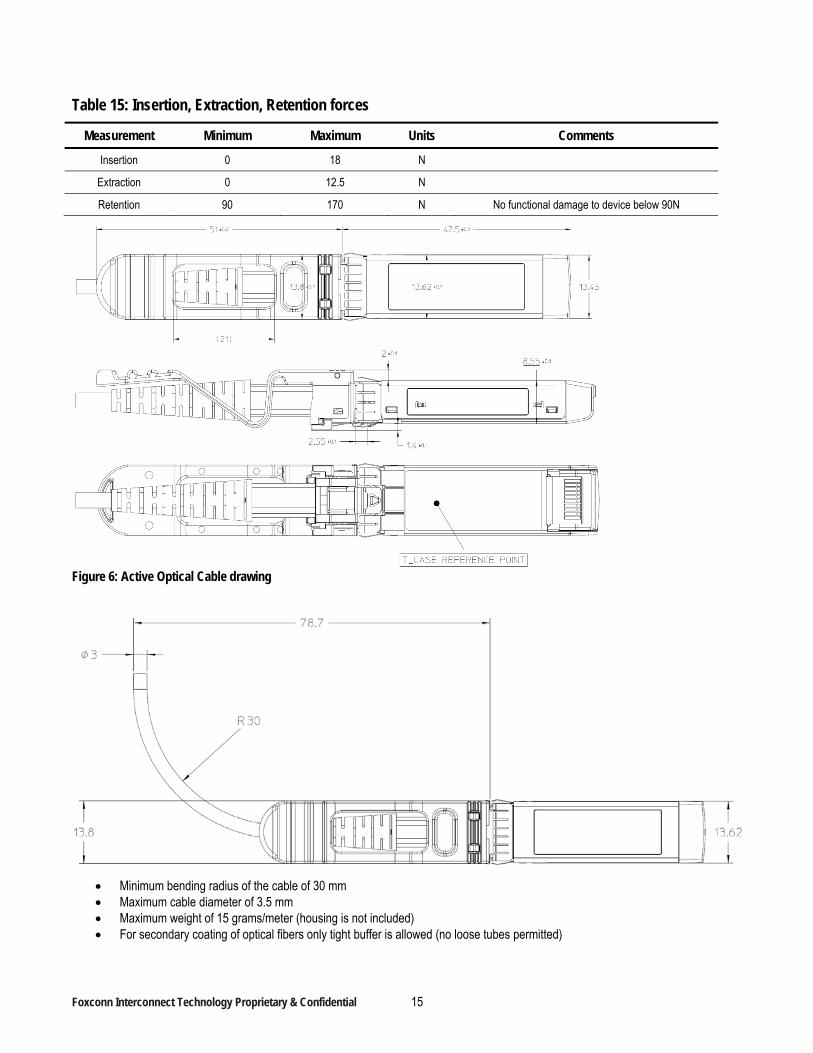
Table 15: Insertion, Extraction, Retention forces
Measurement Minimum Maximum Units Comments
Insertion 0 18 N
Extraction 0 12.5 N
Retention 90 170 N No functional damage to device below 90N
Figure 6: Active Optical Cable drawing
Minimum bending radius of the cable of 30 mm Maximum cable diameter of 3.5 mm Maximum weight of 15 grams/meter (housing is not included) For secondary coating of optical fibers only tight buffer is allowed (no loose tubes permitted)
Foxconn Interconnect Technology Proprietary & Confidential 16
The Direct Attach AOC assembly shall be rated by Underwriters Laboratories as VW-1
Figure 7: Bend Radius Definition
Foxconn Interconnect Technology Proprietary & Confidential 17
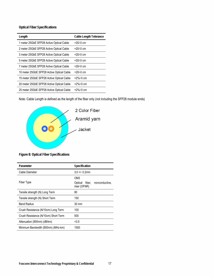
Optical Fiber Specifications
Length Cable Length Tolerance
1 meter 25GbE SFP28 Active Optical Cable +20/-0 cm
2 meter 25GbE SFP28 Active Optical Cable +20/-0 cm
3 meter 25GbE SFP28 Active Optical Cable +20/-0 cm
5 meter 25GbE SFP28 Active Optical Cable +20/-0 cm
7 meter 25GbE SFP28 Active Optical Cable +20/-0 cm
10 meter 25GbE SFP28 Active Optical Cable +20/-0 cm
15 meter 25GbE SFP28 Active Optical Cable +2%/-0 cm
20 meter 25GbE SFP28 Active Optical Cable +2%/-0 cm
25 meter 25GbE SFP28 Active Optical Cable +2%/-0 cm
Note: Cable Length is defined as the length of the fiber only (not including the SFP28 module ends)
Figure 8: Optical Fiber Specifications
Parameter Specification
Cable Diameter 3.0 +/- 0.2mm
Fiber Type OM3
Optical fiber, nonconductive, riser (OFNR)
Tensile strength (N) Long Term 80
Tensile strength (N) Short Term 150
Bend Radius 30 mm
Crush Resistance (N/10cm) Long Term 100
Crush Resistance (N/10cm) Short Term 500
Attenuation (850nm) (dB/km) <3.5
Minimum Bandwidth (850nm) (MHz-km) 1500