Embed Size (px)
Citation preview

2017ACIFRPCompositesCompetition
ReinforcementIdentificationGuideandProductDatasheets
HughesBrothersAslan100#3barhttp://www.aslanfrp.comPultrallV•RodStandard#3barhttp://www.vrod.caTUF-BAR40GPa#3barhttp://tuf-bar.comMarshallCompositeTechnologiesC-Bar#3barhttp://www.marshallcomposite.comFiberlineComBAR8mmbarhttps://fiberline.com/structural-profiles/combar-fiberline
Hughes Brothers, Inc. 210 N. 13th Street Seward NE 68434 www.aslanfrp.com Ph:800-869-0359 [email protected] ©2011
Asla
n 10
0 Fi
berg
lass
Reb
ar
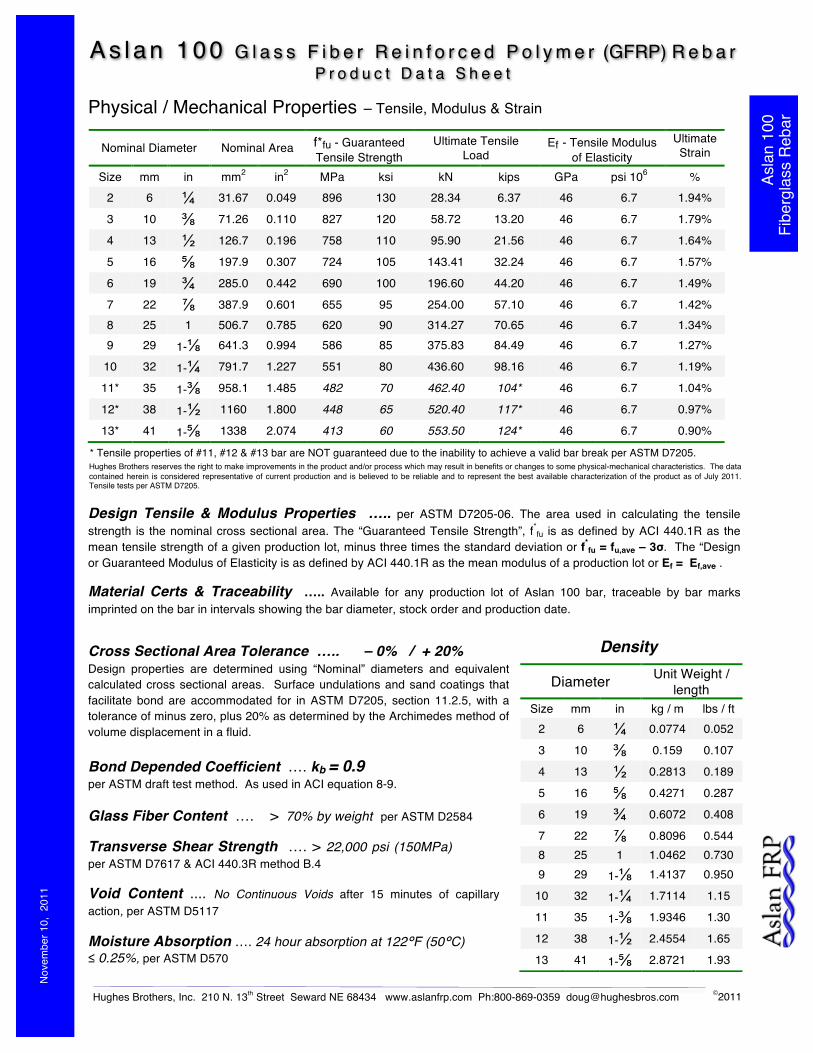
A s l an 100 G l a s s F i b e r R e i n f o r c e d P o l y m e r (GFRP) R e b a r P r o d u c t D a t a S h e e t
Physical / Mechanical Properties – Tensile, Modulus & Strain
Design Tensile & Modulus Properties ….. per ASTM D7205-06. The area used in calculating the tensile strength is the nominal cross sectional area. The “Guaranteed Tensile Strength”, f*fu is as defined by ACI 440.1R as the mean tensile strength of a given production lot, minus three times the standard deviation or f*
fu = fu,ave – 3σ. The “Design or Guaranteed Modulus of Elasticity is as defined by ACI 440.1R as the mean modulus of a production lot or Ef = Ef,ave .
Material Certs & Traceability ….. Available for any production lot of Aslan 100 bar, traceable by bar marks imprinted on the bar in intervals showing the bar diameter, stock order and production date.
Hughes Brothers reserves the right to make improvements in the product and/or process which may result in benefits or changes to some physical-mechanical characteristics. The data contained herein is considered representative of current production and is believed to be reliable and to represent the best available characterization of the product as of July 2011. Tensile tests per ASTM D7205.
Nominal Diameter Nominal Area f*fu - Guaranteed Tensile Strength
Ultimate Tensile Load
Ef - Tensile Modulus of Elasticity
Ultimate Strain
Size mm in mm2 in2 MPa ksi kN kips GPa psi 106 % 2 6 ¼ 31.67 0.049 896 130 28.34 6.37 46 6.7 1.94%
3 10 ⅜ 71.26 0.110 827 120 58.72 13.20 46 6.7 1.79%
4 13 ½ 126.7 0.196 758 110 95.90 21.56 46 6.7 1.64%
5 16 ⅝ 197.9 0.307 724 105 143.41 32.24 46 6.7 1.57%
6 19 ¾ 285.0 0.442 690 100 196.60 44.20 46 6.7 1.49%
7 22 ⅞ 387.9 0.601 655 95 254.00 57.10 46 6.7 1.42% 8 25 1 506.7 0.785 620 90 314.27 70.65 46 6.7 1.34% 9 29 1-⅛ 641.3 0.994 586 85 375.83 84.49 46 6.7 1.27%
10 32 1-¼ 791.7 1.227 551 80 436.60 98.16 46 6.7 1.19%
11* 35 1-⅜ 958.1 1.485 482 70 462.40 104* 46 6.7 1.04%
12* 38 1-½ 1160 1.800 448 65 520.40 117* 46 6.7 0.97%
13* 41 1-⅝ 1338 2.074 413 60 553.50 124* 46 6.7 0.90%
Cross Sectional Area Tolerance ….. – 0% / + 20% Design properties are determined using “Nominal” diameters and equivalent calculated cross sectional areas. Surface undulations and sand coatings that facilitate bond are accommodated for in ASTM D7205, section 11.2.5, with a tolerance of minus zero, plus 20% as determined by the Archimedes method of volume displacement in a fluid.
Density
Diameter Unit Weight / length
Size mm in kg / m lbs / ft 2 6 ¼ 0.0774 0.052
3 10 ⅜ 0.159 0.107
4 13 ½ 0.2813 0.189
5 16 ⅝ 0.4271 0.287
6 19 ¾ 0.6072 0.408
7 22 ⅞ 0.8096 0.544 8 25 1 1.0462 0.730 9 29 1-⅛ 1.4137 0.950
10 32 1-¼ 1.7114 1.15
11 35 1-⅜ 1.9346 1.30
12 38 1-½ 2.4554 1.65
13 41 1-⅝ 2.8721 1.93
* Tensile properties of #11, #12 & #13 bar are NOT guaranteed due to the inability to achieve a valid bar break per ASTM D7205.
Transverse Shear Strength …. > 22,000 psi (150MPa) per ASTM D7617 & ACI 440.3R method B.4
Glass Fiber Content …. > 70% by weight per ASTM D2584
Void Content .... No Continuous Voids after 15 minutes of capillary action, per ASTM D5117
Moisture Absorption …. 24 hour absorption at 122°F (50°C) ≤ 0.25%, per ASTM D570
Nov
embe
r 10,
201
1
Bond Depended Coefficient …. kb = 0.9 per ASTM draft test method. As used in ACI equation 8-9.

2 Hughes Brothers, Inc. 210 N. 13th Street Seward NE 68434 www.aslanfrp.com Ph:800-869-0359 [email protected] ©2011
Asla
n 10
0 Fi
berg
lass
Reb
ar
Characteristic Properties - Characteristic Properties are those that are inherent to the FRP bar and not necessarily measured or quantified from production lot to production lot.
Bent Bars & Stirrups - Must be made at the factory, field bending not permitted. - Industry standard bent shapes are available, standard shape codes are used. Some limitations include:
- Max leg length of a stirrup is 60” (152cm) - Redirection of bends, such as Z-shapes or gull-wings types are not very
economical. Bent shapes should continue in the same circular direction.
- Closed square shapes are best furnished as pairs of U-bars or continuous spirals.
- A 90-degree bend with 12db, bar diameter, pigtail used to shorten development length is equally as effective as a J-shape as per ACI 440.1R.
- The radius on all bends is fixed as per the table shown. Some U-shaped stirrups fall in between the range of these two bend radiuses and are not possible.
We advise that you work closely with the factory to implement the most economical detailing of bent bars and stirrups.
Diameter Inside Bend Radius
Size mm in mm in 2 6 ¼ 38 1.5 3 10 ⅜ 54 2.125 4 13 ½ 54 2.125 5 16 ⅝ 57 2.25 6 19 ¾ 57 2.25
7 22 ⅞ 76 3.0 8 25 1 76 3.0
Field Forming of Large Radius Curves Permitted when the radius is larger than in the following table. The table gives the minimum allowable radius for induced bending stresses without any consideration for additional sustained structural loads.
Bend Radius
Strength of the Bent Portion of the Bar …. > 50% strength of the straight length of the bar , per ACI 440.3R method B.5
Tensile Strength at Cold Temperature …. < 5% strength reduction from ambient at -40°F (-40°C), per ASTM D7205.
Durability – Alkali Resistance ~ without load …. > 80% strength retention, when exposed to 12.8pH solution for 90 days at 140°F (60°C)
Transition Temperature of Resin - Tg .... > 230°F (110°C) per DSC method
Handling and Placement - Follow guidelines in ACI440.5-08 “Specification for Construction with FRP Bars”. - In general, field handling and placement is the same as for epoxy or galvanized steel bars. - Do NOT shear FRP bars. When field cutting of FRP bars is necessary, use a fine blade saw, grinder, carborundum or diamond blade.
- Sealing the ends of FRP bars is not necessary. - Support chairs are required at two-thirds the spacing of steel rebar. - Plastic coated tie wire is the preferred option for most projects. When completely non-ferrous reinforcing, i.e., no steel is required in the concrete, nylon zip ties (available from local building materials centers) or plastic bar clips are recommended. (Don’t forget to use non-metallic form ties in formwork.)
- It is possible, especially in precast applications, for GFRP bars to “float” during vibrating. Care should be exercised to adequately secure GFRP in the formwork.
Diameter Interior Use
Ce = 0.8 Min Radius
Exterior Use Ce = 0.7
Min Radius Size mm in cm in cm in
2 6 ¼ 107 42 122 48
3 10 ⅜ 170 67 196 77
4 13 ½ 246 97 282 111
5 16 ⅝ 323 127 368 145
6 19 ¾ 404 159 462 182
7 22 ⅞ 495 195 566 223 8 25 1 597 235 678 267 9 29 1-⅛ 711 280 813 320
10 32 1-¼ 871 343 996 392
11 35 1-⅜ 1052 414 1204 474
12 38 1-½ 1237 487 1412 556
13 41 1-⅝ 1448 570 1656 652

Revision: July 2013
V-Rod standard straight bars only, does not apply to bent bars #2 GFRP #3 GFRP #4 GFRP #5 GFRP #6 GFRP #7 GFRP #8 GFRP
V•ROD V•ROD V•ROD V•ROD V•ROD V•ROD V•ROD
MPa 990 1100 1140 1130 1110 1100 800
ksi 143 159 165 164 161 159 116
GPa
ksi
Tensile strain % 1,89 2,10 2,17 2,15 2,11 2,10 1,52
Poisson's ratio (-) 0,25 0,21 0,26 0,25 0,25 0,25 0,28
MPa 1200 1161 1005 930 882 811 776
ksi 174 168 146 135 128 117 112
GPa 48,8 46,1 46,8 46,8 45,1 44,6 45,1
ksi 7071 6685 6787 6786 6533 6466 6539
Flexural strain % 2,46 2,52 2,15 1,99 1,96 1,82 1,72
MPa
psi
Bond dependent coefficient (-)
xE-6/°C
xE-6/°F
52,5 ±2,5
7609 ±363
0,8
Longitudinal coefficient of thermal expansion6,2
3,5
STANDARD
Minimum guaranteed tensile strength *
Nominal tensile modulus
Nominal Flexural strength
Nominal Flexural modulus
Nominal Bond strength14
2029
xE-6/°F
xE-6/°C
xE-6/°F
Moisture absorption % 0,65 0,47 0,38 0,25 0,21 0,36 0,17
% vol
% weight
g/m 95 181 298 488 659 887 1132
lb/ft 0,064 0,122 0,200 0,328 0,443 0,596 0,761
mm2
47,0 95,0 149,0 234,0 302,0 396,0 546,0
inch2
0,0729 0,1473 0,2310 0,3627 0,4681 0,6138 0,8463
mm2
31,7 71,3 126,7 197,9 285,0 387,9 506,7
inch2
0,0491 0,1104 0,1963 0,3068 0,4418 0,6013 0,7854
** Please contact the manufacturer for dowelling applications.
Please refer to the bent bar data sheet for designs using bent V-Rod bars.
* the minimum guaranteed tensile strength must not be used to calculate the strength of the bent portion of a bent bar. Instead use the minimum guaranteed tensile strength found in the
technical data sheet of bent V-Rod bars.
Development and splice lengths are available upon request but should be properly calculated by a design engineer.
It is the responsibility of the design engineers to contact the bar manufacturer to get the latest updates of this technical data sheet (also available at
www.pultrall.com).
Glass content 65
83
Weight
Effective cross-sectional area (including sand coating) **
Nominal cross-sectional area
3,5
Transverse coefficient of thermal expansion23,8
13,2
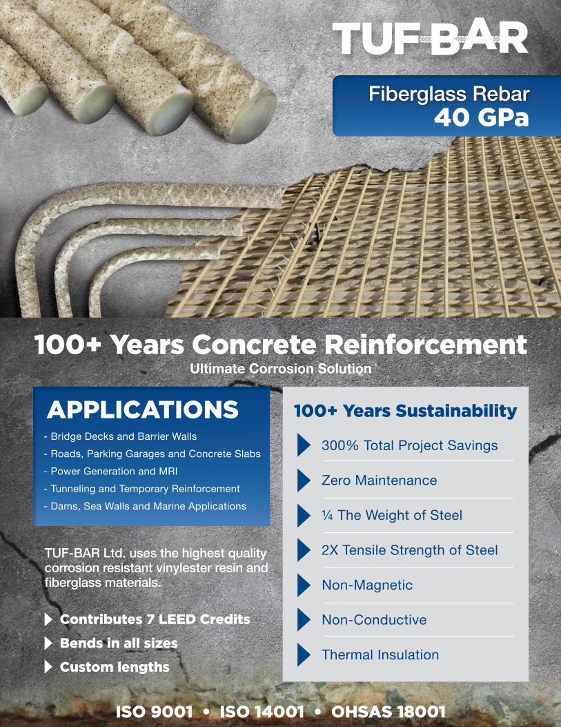
100+ Years Concrete Reinforcement Ultimate Corrosion Solution
40 GPa
APPLICATIONS- Bridge Decks and Barrier Walls- Roads, Parking Garages and Concrete Slabs- Power Generation and MRI- Tunneling and Temporary Reinforcement- Dams, Sea Walls and Marine Applications
100+ Years Sustainability
300% Total Project Savings
Zero Maintenance
¼ The Weight of Steel
2X Tensile Strength of Steel
Non-Magnetic
Non-Conductive
Thermal Insulation
Contributes 7 LEED Credits
Bends in all sizes
Custom lengths
TUF-BAR Ltd. uses the highest quality corrosion resistant vinylester resin and fiberglass materials.
ISO 9001 • ISO 14001 • OHSAS 18001
Fiberglass Rebar

TUF-BAR® 40 GPa Straight Bars
Average Ultimate Tensile Strength(ASTM D7205 / CAN/CSA-S806)
Mpa 1124.0 948.6 1017.2 997.7 947.3 921.8ksi 163.0 137.6 147.5 144.7 137.4 133.7
Minimum Guaranteed Ultimate Tensile Strength(ASTM D7205 / CAN/CSA-S806)
MPa 983.8 845.4 921.0 884.3 878.4 818.6ksi 142.7 122.6 133.6 128.3 127.4 118.7
Minimum Guaranteed Ultimate Tensile Capacity(ASTM D7205 / CAN/CSA-S806)
kN 69.8 109.1 183.3 251.1 339.9 417.5lbf 15702 24517 41202 56457 76420 93849
Minimum Modulus of Elasticity(ASTM D7205 / CAN/CSA-S806)
Gpa 49.1 45.6 48.8 51.0 49.6 52.0ksi 7115 6608 7079 7395 7195 7547
Ultimate Elongation % 2.3 2.1 2.1 2.0 1.9 1.8
Average Bond Strength(ACI 440.3R B3)
MPa 17.4 12.7 15.1 14.4 13.6 13.5ksi 2.5 1.8 2.2 2.1 2.0 2.0
Transverse Shear Strength(ACI 440.3R B4)
Mpa 219.3 209.7 202.7 190.3 199.2 183.5ksi 31.8 30.4 29.4 27.6 28.9 26.6
Transverse Shear Capacity(ACI 440.3R B4)
kN 31.1 54.1 80.7 108.1 154.2 187.2lbf 7001 12165 18136 24296 34658 42079
Longditudinal Thermal Expansion Coefficient(ASTM E831)
10-6/°C 7.9 8.6 6.7 7.3 8.9 8.710-6/°F 4.4 4.8 3.7 4.0 5.0 4.8
Transverse Thermal Expansion Coefficient(ASTM E831)
10-6/°C 21.7 24.2 25.4 23.6 24.5 25.210-6/°F 12.1 13.4 14.1 13.1 13.6 14.0
Water Absorption (ASTM D570) % 0.5 0.5 0.5 0.4 0.4 0.3
Linear Weight g/m 150 259 433 611 816 1105lb/ft 0.10 0.17 0.29 0.41 0.55 0.74
Effective Cross Sectional Area (including coating)(CSA S807 Annex A)
mm² 72 123 203 290 399 530inch² 0.111 0.190 0.315 0.450 0.618 0.821
Nominal Cross Sectional Area(CSA S807)
mm² 71 129 199 284 387 510inch² 0.110 0.200 0.308 0.440 0.600 0.791
Effective Diameter (including coating)(CSA S807 Annex A)
mm 9.6 12.5 16.1 19.2 22.5 26.0inch 0.377 0.492 0.633 0.757 0.887 1.022
Nominal Diameter(CSA S807)
mm 10 13 15 20 22 25inch 3/8 1/2 5/8 3/4 7/8 1
Units #3-40 #4-40 #5-40 #6-40 #7-40 #8-40
1887
AMERICAN COMPOSITES MANUFACTURERS ASSOCIATION
Meets Current Design Codes and Standards
Bridge: AASHTO GFRP-1Design: ACI 440-1R-15Material Specification: ACI 440.6-08
Bridge Code: CSA-S6-14Design Standard: CSA-S806-12Material Specification: CSA-S807-10
ISO 9001 LEED Credits
1.888.99.REBAR1.888.997.3227 [email protected]
CANADA5522-36 Street NWEdmonton, AB, T6B 3P3
USA111 2nd Avenue NE, #900 St Petersburg, FL, 33701WWW.TUF-BAR.COM

Product Guide Specification
A. Marshall Composite Technologies, LLC, 2873 22nd
St. NE, Salem, OR 97302. Phone (503)726-0526. Web Site http://www.marshallcomposite.com.
F. Dimensions: Nominal Diameter and Sectional Area:
US Size Nominal Diameter,
inches
Area, in
2
Weight, lb/ft Soft Metric Size
Nominal Diameter,
mm
Area, mm
2
Weight, Kg/m
#3 0.375 0.110 0.10 #10 9.5 71 0.046
#4 0.500 0.196 0.17 #13 12.7 126 0.077
#5 0.625 0.307 0.28 #16 15.9 198 0.127
#6 0.750 0.442 0.41 #19 19.0 285 0.186
G. Tensile Properties:
Bar Size Designation
Tensile Modulus of Elasticity
Ultimate Tensile Strength
Guaranteed Design Tensile Strength
Allowable Tensile Stress (Working Stress Limit)
Ultimate Strain in Tension
Poisson’s Ratio
Eτ Fu ffu ff,a εfu μ
mm in Gpa Msi MPa Ksi MPa Ksi MPa Ksi %
#10 #3 42 6 840 121 780 113 195 28 2.00 0.27
#13 #4 42 6 800 116 725 105 181 26 1.90 0.27
#16 #5 40 5.8 780 113 655 95 164 24 1.95 0.27
#19 #6 40 5.8 720 104 630 91 158 23 1.80 0.27
I. Coefficient of Thermal Expansion (C.T.E.):
1. Longitudinal Direction: 8 x 10⁻⁶ per degree C (4.5 x 10⁻⁶ per degree F). 2. Transverse Direction: 32 x 10-6 per degree C (18 x 10-6 per degree F).

Published on Fiberline Composites (https://fiberline.com)
Home > Straight bars
Straight bars
Bar sizes, dimensions, weights, ultimate tensile strength
ComBAR®
bardesignated diam.(ACI/CSA)
core diam.(mm)
exterior diam.(mm)
specific weight(kg/m)
ø 8 M8 8 9 0.13ø 13 M13 13 13.5 0.30ø 16 M15 16 18 0.53ø 20 M20 20 22 0.80ø 25 M25 25 27 1.22ø 32 M32 32 34 1.93
Material properties of straight bars
properties values comments

ultimate tensile strength > 1,000 MPa all bar diameters
1,000 hour tensile strength1) 950 MPa 5th percentile
logarithmic temporal slope1) < 15 % 5th percentile
modulus of elasticity > 63.5 GPa 8, 12, 16, 25 mm 2)
ultimate elongation 1.67% ø 16mm bar 2)
bond strength 12.2 MPa ø 16mm bar
bar surface profile factor(bond) ≤ 1.0 (CSA S806 9.3)
bond coefficient 0.6 3) (CHBDC 16.8.2.3)
bar surface factor ≤ 0.8 (CHBDC 16.8.4.1)
transverse shear strength4) ≥ 150 MPa acc. CSA / ACI
min. concrete cover d + 10 mm/d + 5 mm (pre-cast)
min. cover for loadtransfer
fibre content > 75 % (vol) no secondary fibres orfillers
void ratio < 1%–

1) values for determination of design value of tensile strength according to durability concept offib defining time-to-failure lines2) values for 16mm ComBAR® bars (certification of compliance with ISIS specifications/CSAS807, University of Toronto); certifications for 8, 12, 16, 25 mm bars completed3) value determined for ComBAR® bars of all diameters4) values in tests according to CSA / ACI not for design of dowels. Ongoing test series shownsubstantially higher values.
The Quality of all components of the ComBAR® reinforcement system is continuously tested aspart of the Quality Control program of Fiberline Composites,
[1]
Source URL: https://fiberline.com/straight-bars
Links[1] https://www.addtoany.com/share_save#url=https%3A%2F%2Ffiberline.com%2Fstraight-bars&title=Straight%20bars