Embed Size (px)
Citation preview

4
2017AwardNominationTitleofInnovation:UltrasoundCathodicProtectionTestStationNominee(s)Eugene(Gene)B.SilvermanPhD,BerkeleySpringsInstrumentsLLCCategory:CathodicProtectionCoatingsandLinings InstrumentationCathodicProtection TestingMaterialsDesign IntegrityAssessmentChemicalTreatment Other—fillinDatesofInnovationDevelopment:January,2014toJuly2015Website:www.bsisentry.comSummaryDescription:
For years, metal coupons have been used for measuring the level of cathodic protection (CP) of buried or submerged structures such as pipelines, steel pylons, jetties, etc. CP coupons are typically installed near the structure that is being protected and their leads terminated at an aboveground access point often referred to as a “test station.” In theory, by connecting the coupon to the CP system via the structure, the coupon mimics an exposed area of the structure such as a surface defect or coating holiday. To one extent or another coupons are designed to (1) determine the ability of the local CP system to provide adequate structural protection and, (2) to determine, through inference, the mechanical integrity of the underground structure. CP system performance effectiveness is achieved if the industry-accepted level of protection available to the structure is measured at or below -850 mV DC. This value often changes due to factors that are related to CP system performance, ground moisture concentration, soil resistance, the presence of stray current, the existence of extraneous AC and DC electromagnetic fields and other factors. As a result, traditional coupon potential measurements are not always consistent or representative of what the structure is actually experiencing and the reliability of coupon test stations and the data they acquire are often in question. Consequently, proper maintenance planning and risk mitigation objectives are difficult to achieve. It would be of great benefit if a more direct measurement of the structures integrity was available. The UT CP Test Station solves this problem by directly measuring the amount of coupon metal loss through the use of ultrasound transducers, imbedded inside of metal coupons. The innovation of

5
imbedded thickness measurement transducers augments traditional coupons by providing an increased level of measurement precision while maintaining the ability to provide traditional test station information. A coupon’s thickness is anticipated to change as the thickness of the underground structure changes. Consequently, a direct measure rather than an inferred measured of rate of material loss is provided. Both potential measurements and metal thickness measurements are acquired by the UT CP Test Station. As a result, the UT CP Test Station data are easily incorporated into existing corrosion prevention and control activities. The thickness of the coupon can be measured at any time with a suitable ultrasound pulser/receiver instrument at the test station. There are a number of significant cost and operational advantages inherent in the use of an UT CP Test Station in addition to the significance of data accuracy and measurement precision – all factors that provide significant industry benefits. The recently developed UT CP Test Station is now commercially available.

6
FullDescription:
1.Whatistheinnovation?
One of the primary objectives of a cathodic protection (CP) test stations is to determine the level of protection for a buried or submerged structure by a local cathodic protection system. Commonly used CP coupons are installed adjacent to the structure being monitored and typically connected to an above grade test station. As noted in NACE ANSI/NACE Standard RP0104-2004, “this allows the CP coupon to be connected to the CP system on the structure, thus simulating a similar-sized bare area of the structure’s surface, such as a holiday in the coating.” , a second “native” coupon (a coupon which is located outside of the CP system impressed current or passive anode field) is installed to measure the free-corrosion potential of the structure under open-circuit conditions.
There are a number of industry guidance documents that provide criteria for determining the CP status of underground or submerged structures. These include recording voltage and current density information, and related test methods for evaluating the CP system’s compliance with industry standards. They can be used where there is a direct connect to galvanic anodes which can not be interrupted. CP coupons are also very useful for measuring the structure-to-earth potentials without interrupting multiple CP sources. Additionally, measurements can be made without de-energizing the CP system. Finally, the impact of stray currents on structures can be determined by measuring their impact on structure-to-electrolyte potentials.
There are disadvantages and technical shortcomings associated with the use of coupons. These include:
a. Performance variability due to environmental conditions
b. Cost of access (excavation removal) and analysis
c. Underground stray current interference
d. HVAC interference
e. Lack of precise correlation of coupon-measured CP protection and actual structure metal loss.
As a result, and in some instances, operators are reluctant to use coupon data for determining corrosion rates. Consequently, there is a critical need for more direct and precise method for determining underground and submerged structure external material loss rates.
Ultrasound technology is a well-known measurement technique that has deep roots within the non-destructive testing community. The technique is well understood and a wide range of instrumentation exists for the interpretation of ultrasound data. Indeed, there are a host of standards and a number of academic and industry training and certification resources provided by the American Society of Non-Destructive Testing (ASNT). If the use of ultrasound could be used to evaluate metal loss of a sacrificial coupon and if this loss could be associated with an underground or submerged structures, then (1) a major advancement for the industry could be achieved for evaluating the effectiveness of cathodic protection systems and (2) precise external corrosion rates of structures can be determined. The use of ultrasound technology for precisely evaluating corrosion coupon integrity and integrating this capability into traditional CP potential measurements, within the same test station, is the primary achievement of the UT CP Test Station.
Precise and repeatable pipeline mechanical health data upon which to make integrity assessments as well forecasting future loss can now be made with a higher degree of confidence. The innovations inherent

7
within the UT CP Test Station design are associated with the use of precise ultrasound and its integration into currently used conventional voltage and current density measurements (AC and DC).
2. How does the innovation work?
The UT CP Test Station uses two independent circular metal coupons, each imbedded with 2 to 3 ultrasonic transducers that can be pulsed and interrogated by an operator through a conventional test station. Packaged in the shape of a “hockey puck” the transducer-coupon assemblies are waterproof and are installed in any configuration on or near the underground structure that it is monitored. Ten (10) square centimeters of exposed coupon surface is used to monitor and track metal loss within a DC field and a one (1) square centimeter of exposed coupon metal is used to monitor and track metal loss within an AC field. The coupon metal loss data is acquired during typical “walk-up” test station interrogations or the data can be transmitted wirelessly with a properly configured wireless communication system.
The UT CP Test Station has two simultaneous modes of operation: The acquisition of DC/AC conventional current density measurements and coupon metal thickness measurement using ultrasound transducers. The first mode provides some degree of evaluation of external corrosion using polarization resistance within different soil environments. The second, more precise mode, yields actual corrosion rates based on the material properties of the structure being monitored. How each mode works is described below. Mode 1: Polarization potential measurement
With a cathodic protection system, industry accepted criteria involve the measurement of the electrochemical potential of the structure to establish the level of cathodic protection sufficient to mitigate corrosion of the buried metal structure. The ordinary practice to determine the necessary level of cathodic protection is to measure the potential difference between the buried structure, which is an electrode, and a reference electrode placed, at grade, in contact with the soil, which is an electrolyte. However, when this measurement is taken while the cathodic protection system is operating, a voltage drop through the soil due to the cathodic protection current, referred to as the IR (voltage) drop, causes an error in the potential measurement.
In order to measure a potential that is free of IR drop, it is common to measure the potential immediately following interruption of the cathodic protection current. The instantaneous voltage drop that occurs immediately after the cathodic protection is turned off is equal to the IR drop caused by the interrupted cathodic protection current. Because the electrochemical interface of the protected structure has a capacitive component, the potential of that interface does not change immediately following interruption as does the IR drop. Therefore, the potential measured immediately following interruption of the cathodic protection current, when current, I, is zero, is the potential of the protected structure free of IR drop. This potential is referred to as off-potential.
Problems arise in interrupting the cathodic protection. Extremely long buried pipelines have multiple cathodic protection stations, all of which must be interrupted simultaneously, or interrupted using a non-synchronous method in which all of the IR drops are summed. Galvanic cathodic protection systems are not designed to be interrupted because the anodes are typically directly connected to the protected structure. Additionally, second-party cathodic protection systems that are either unknown or cannot be interrupted may be present in the area. Other problems exist, also, such as stray current effects, e.g., from power distribution systems, DC transit systems, etc., that are not interruptible, and rapid IR transients. For instance, AC current magnetic fields created in the vicinity of high voltage power lines can propagate into the earth and induce corrosion. This is known as AC-induced corrosion. Such corrosion on cathodically protected underground pipelines is commonly the result of a combined action of the induced AC voltage,

8
the cathodic protection conditions, a piping coating defect and the chemical and physical conditions of the soil. As a result, both DC and AC current fields can influence corrosion of underground structures.
In order to avoid the problems associated with interruption of the entire cathodic protection system, “coupons” are used to monitor the level of cathodic protection on buried metal structures. The coupon is a bare metal sample having substantially the same metallurgical attributes as the pipe or other structure being monitored. The coupon is placed in the soil near the pipe and connected to the pipe. Therefore, the coupon is exposed to the same cathodic protection current source as the pipe. The connection between the pipe and the coupon is interrupted for a time period, during which time the potential difference between the coupon and a reference electrode is measured. The pipe's cathodic protection is never interrupted, since only the pipe-to-coupon connection is interrupted. The coupon's potential simulates the potential of a pipe coating defect of a similar surface area as the coupon. The coupon's potential can be measured without interrupting the cathodic protection to the pipe, and therefore without some of the problems inherent in interrupting the entire cathodic protection system. In addition, once the coupon is interrupted, it is an isolated, small piece of metal in the soil and stray currents are eliminated from its surface. In contrast, stray currents are generally not eliminated from a pipeline upon interruption of the entire cathodic protection system.
Mode 2: Augmentation with the use of ultrasound
The UT CP Test Station solves many of the indirect measurement challenges of conventional coupons by providing a coupon imbedded with one or more ultrasonic transducers that can determine the thickness of the coupon and can be energized and read from the surface by an operator with a suitable ultrasound pulse/receiver instrument. The piezoelectric ultrasound transducer converts the pulse of electrical energy into an acoustic pressure wave (sound). The pressure wave is coupled to the surface of a plate via an innovative silicon-based couplant. The transducers are positioned directly underneath the coupon’s surface and can, on operator demand at the test station, measure the thickness of the coupon. The coupon’s thickness changes as the metallurgy of the underground structure changes. This information provides a direct rather than an inferred measure of rate of material loss due to any corrosion activity that may be occurring with the underground structure under protection.
This 2-mode measurement capability now provides the operator with all the functionality associated with traditional cathodic protection test stations. However, the addition of the ultrasonic coupons located within each probe provides the operator with the added ability to directly monitor metal loss, a more accurate assessment of underground structural integrity.
3. Describe the corrosion problem or technological gap that sparked the development of theinnovation?Howdoes the innovation improve upon existingmethods/technologies to address thiscorrosionproblemorprovideanewsolutiontobridgethetechnologygap?
3.1Describethecorrosionproblemortechnologicalgapthatsparkedthedevelopmentoftheinnovation?
For years, metal coupons have been used for measuring the level of cathodic protection (CP) of buried or submerged structures such as pipelines. CP coupons are typically installed near the structure that is being protected and their leads terminated at an aboveground test station. In theory, by connecting the coupon to the CP system via the structure, it mimics an exposed surface of the structure such as a surface defect or coating holiday. The use of coupons and the associated measures to determine the effectiveness of CP systems is geared, to one extent or another, to (1) determine the effective contribution of the local CP system to provide adequate structural protection and, (2) to determine, through inference, the mechanical integrity of the underground structure.

9
The effectiveness of CP system performance is achieved when the level of protection available to the structure is measured at or below -850 mV DC. This industry-accepted criterion is widely used; however, this value changes due to factors that are more related to the characteristics of the ground such as moisture content, the resistance of the soil to current transmission, the presence of stray current, the existence of AC and DC overhead power and a host of other factors.
As a result, traditional coupon potential measurements are not always consistent or representative of what the structure is actually experiencing. Consequently, the reliability of coupon test stations and the data they acquire are often in question and proper maintenance planning and risk mitigation can be difficult to achieve. Additionally, oftentimes, the operator will have to dig-up the coupon, clean, ship and wait for laboratory analysis results in order to measure corrosion rates. It would be of great benefit if a more direct measurement of the structures integrity was available, especially without the complexity associated with digging up the coupon and incurring all of the associated analysis costs.
3.2 How does the innovation improve upon existingmethods/technologies to address thiscorrosionproblemorprovideanewsolutiontobridgethetechnologygap?
The UT CP Test Station solves this problem by directly measuring the amount of coupon metal loss through the use of ultrasound transducers, imbedded inside of metal coupons. The innovation of imbedded thickness measurement transducers serves to augment traditional coupons by providing an additional level of measurement while maintaining the ability to provide traditional test station information. The coupon’s thickness changes as the metallurgy of the underground structure changes and provides a direct rather than an inferred measure of rate of material loss. As long as the metal coupon is exposed to the same conditions as the monitored structure, the coupon rate of metal loss can be used to directly monitor both the effectiveness of a local CP system as well as the mechanical integrity of the structure. Both potential measurements and metal thickness measurements are acquired by The UT CP Test Station. As a result, the UT CP Test Station data can be easily incorporated into existing corrosion prevention and control activities. The thickness of the coupon can be measure at any time with a suitable ultrasound pulser/receiver instrument at the test station. There are a number of significant advantages inherent in the use of an UT CP Test Station including data accuracy and measurement precision, ease of use by any commercially-available ultrasound flaw detector, improvements in operations planning and significant reduction in monitoring costs – all factors that provide significant industry benefits. Additionally, there is no need to dig up the coupon for laboratory analysis.
Finally, as cited in NACE SP0502-2008, Appendix D 1.2, “When possible corrosion rates should be determined by directly comparing measured wall thickness changes that are detected after a known time interval……” And in Section D 1.3.1, “Consideration of the external corrosion history on the pipe or segment being evaluated or in “like/similar” areas that contain the same pipe materials and similar environments.”

10
Coupon3Thickness
4.Hastheinnovationbeentestedinthelaboratoryorinthefield?Ifso,pleasedescribeanytestsorfielddemonstrationsandtheresultsthatsupportthecapabilityandfeasibilityoftheinnovation.
The UT CP Test Station has undergone extensive laboratory and field testing. Additionally, a number of on-going, long term laboratory tests are being conducted by the original equipment manufacturer and two industry users. Results from a recent customer/OEM study are presented in Figure 4-1 and Figure 4-2.
To date, there have been over 80 installations in a wide variety of electrolyte environments. Additionally, a number of UT CP Test Stations have been configured for wireless operations. An example of the user interface associated with a typical wireless UT CP Test Station is shown in Figure 4-3.
Figure 4-1. Example of constant and instant off coupon readings from the UT CP Test Station for “protected” coupon #2.
Figure 4-3. UT CP Test Station data posted to an Internet-based corrosion rate and potentiometer summary user interface.
a b
Figure 4-2. Example of minimal thickness change with (a) “protected” coupon #2 and (b) native (“unprotected”) coupon #3. Note the change in thickness over time. Corrosion rates for “protected” coupons were calculated to be 0-1 mils per year. The corrosion rates for coupons in the unprotected area were 3 – 6 mils per year.
CouponThickness(inches)
CouponThickness(inches)
Coupon2Thickness
Time8-2-16 10-2-16
11
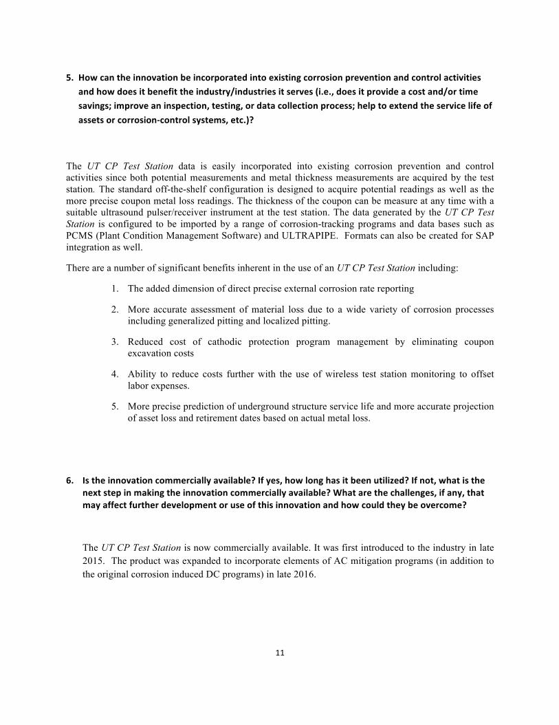
5. Howcantheinnovationbeincorporatedintoexistingcorrosionpreventionandcontrolactivitiesandhowdoesitbenefittheindustry/industriesitserves(i.e.,doesitprovideacostand/ortimesavings;improveaninspection,testing,ordatacollectionprocess;helptoextendtheservicelifeofassetsorcorrosion-controlsystems,etc.)?
The UT CP Test Station data is easily incorporated into existing corrosion prevention and control activities since both potential measurements and metal thickness measurements are acquired by the test station. The standard off-the-shelf configuration is designed to acquire potential readings as well as the more precise coupon metal loss readings. The thickness of the coupon can be measure at any time with a suitable ultrasound pulser/receiver instrument at the test station. The data generated by the UT CP Test Station is configured to be imported by a range of corrosion-tracking programs and data bases such as PCMS (Plant Condition Management Software) and ULTRAPIPE. Formats can also be created for SAP integration as well.
There are a number of significant benefits inherent in the use of an UT CP Test Station including:
1. The added dimension of direct precise external corrosion rate reporting
2. More accurate assessment of material loss due to a wide variety of corrosion processes including generalized pitting and localized pitting.
3. Reduced cost of cathodic protection program management by eliminating coupon excavation costs
4. Ability to reduce costs further with the use of wireless test station monitoring to offset labor expenses.
5. More precise prediction of underground structure service life and more accurate projection of asset loss and retirement dates based on actual metal loss.
6. Istheinnovationcommerciallyavailable?Ifyes,howlonghasitbeenutilized?Ifnot,whatisthenextstepinmakingtheinnovationcommerciallyavailable?Whatarethechallenges,ifany,thatmayaffectfurtherdevelopmentoruseofthisinnovationandhowcouldtheybeovercome?
The UT CP Test Station is now commercially available. It was first introduced to the industry in late 2015. The product was expanded to incorporate elements of AC mitigation programs (in addition to the original corrosion induced DC programs) in late 2016.

12
7.Arethereanypatentsrelatedtothiswork?Ifyes,pleaseprovidethepatenttitle,number,andinventor.
Patent Title: Ultrasonic Cathodic Protection Test Station
Patent Number:
Patent Pending: US Patent Number: 62/213,813
Foreign (PCT) Patent Number: PCT/US2016/050117
Inventor: Eugene B. Silverman, Ph.D.