Embed Size (px)
Citation preview
2019 ALTIMA SEDANOWNER’S MANUAL
and MAINTENANCE INFORMATION
For your safety, read carefully and keep in this vehicle.
Owner’s Manual Supplement
The information contained within this supplement updates the following informa-tion in the 2019 NISSAN Altima Owner’s Manual:
∙ “VEHICLE INFORMATION DISPLAY” in the “Instruments and controls” section of theOwner’s Manual
∙ “LANE DEPARTURE WARNING (LDW)” in the “Starting and driving” section of theOwner’s Manual
∙ “INTELLIGENT LANE INTERVENTION” in the “Starting and driving” section of theOwner’s manual
Read carefully and keep in vehicle.
Printing: October 2018Publication No. SU19EA 0L34G0
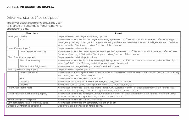
Driver Assistance (if so equipped)The driver assistance menu allows the userto change the settings for driving, parking,and braking aids.
Menu item ResultEmergency Brake Displays available emergency braking options.
Front Allows user to turn the front emergency braking system on or off. For additional information, refer to “IntelligentEmergency Braking” , “Intelligent Emergency Braking with Pedestrian Detection” and “Intelligent Forward CollisionWarning” in the “Starting and driving” section of this manual.
Lane (if so equipped) Displays available lane options.Lane Departure Warning Allows user to turn the Lane Departure Warning (LDW) system on or off. For additional information, refer to “Lane
Departure Warning (LDW)” in the “Starting and driving” section of this manual.Blind Spot (if so equipped) Displays available blind spot options.
Blind Spot Warning Allows user to turn the Blind Spot Warning (BSW) system on or off. For additional information, refer to “Blind SpotWarning (BSW)” in the “Starting and driving” section of this manual.
Side Indicator Brightness Allows user to change the brightness of the side indicator.Parking Aids (if so equipped) Displays available parking aids.
Auto Show Sonar Allows user to auto display the sonar. For additional information, refer to “Rear Sonar System (RSS)” in the “Startingand driving” section of this manual.
Rear Allows user to turn the rear sonar on or off.Distance Allows user to set the distance sensor range to Long/Medium/Short.Volume Allows the user to set the parking sensor volume to High/Medium/Low.
Rear Cross Traffic Alert Allows user to turn the Rear Cross Traffic Alert (RCTA) system on or off. For additional information, refer to “RearCross Traffic Alert (RCTA)” in the “Starting and driving” section of this manual.
Driver Attention Alert (if so equipped) Allows user to turn the Intelligent Driver Alertness on or off. For additional information, refer to “Intelligent DriverAlertness” in the “Starting and driving” section of this manual.
Timer Alert (if so equipped) Allows user to turn the set the timer alert.Low Temperature Alert (if so equipped) Allows user to turn the low temperature alert on or off.Chassis Control (if so equipped) Displays available chassis control options.
VEHICLE INFORMATION DISPLAY
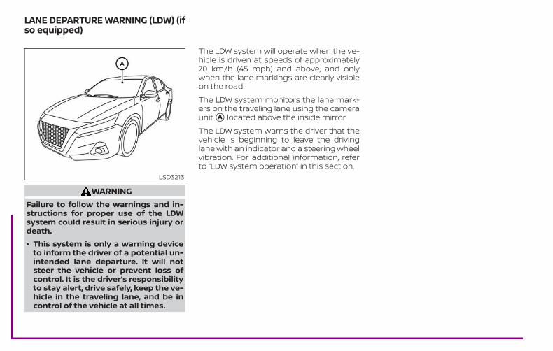
WARNINGFailure to follow the warnings and in-structions for proper use of the LDWsystem could result in serious injury ordeath.
∙ This system is only a warning deviceto inform the driver of a potential un-intended lane departure. It will notsteer the vehicle or prevent loss ofcontrol. It is the driver’s responsibilityto stay alert, drive safely, keep the ve-hicle in the traveling lane, and be incontrol of the vehicle at all times.
The LDW system will operate when the ve-hicle is driven at speeds of approximately70 km/h (45 mph) and above, and onlywhen the lane markings are clearly visibleon the road.
The LDW system monitors the lane mark-ers on the traveling lane using the cameraunit �A located above the inside mirror.
The LDW system warns the driver that thevehicle is beginning to leave the drivinglane with an indicator and a steering wheelvibration. For additional information, referto “LDW system operation” in this section.
LSD3213
LANE DEPARTURE WARNING (LDW) (ifso equipped)
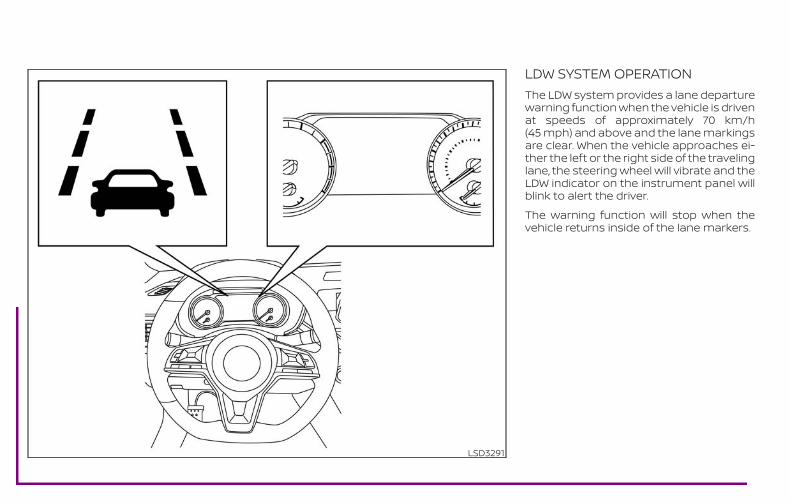
LDW SYSTEM OPERATIONThe LDW system provides a lane departurewarning function when the vehicle is drivenat speeds of approximately 70 km/h(45 mph) and above and the lane markingsare clear. When the vehicle approaches ei-ther the left or the right side of the travelinglane, the steering wheel will vibrate and theLDW indicator on the instrument panel willblink to alert the driver.
The warning function will stop when thevehicle returns inside of the lane markers.
LSD3291
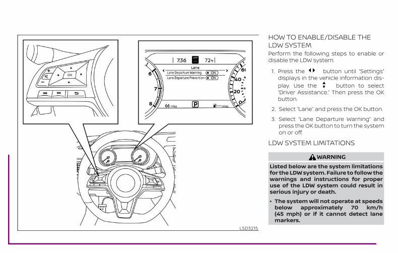
HOW TO ENABLE/DISABLE THELDW SYSTEMPerform the following steps to enable ordisable the LDW system.
1. Press the button until “Settings”displays in the vehicle information dis-play. Use the button to select“Driver Assistance.” Then press the OKbutton.
2. Select “Lane” and press the OK button.
3. Select “Lane Departure Warning” andpress the OK button to turn the systemon or off.
LDW SYSTEM LIMITATIONS
WARNINGListed below are the system limitationsfor the LDW system. Failure to follow thewarnings and instructions for properuse of the LDW system could result inserious injury or death.
∙ The system will not operate at speedsbelow approximately 70 km/h(45 mph) or if it cannot detect lanemarkers.
LSD3215
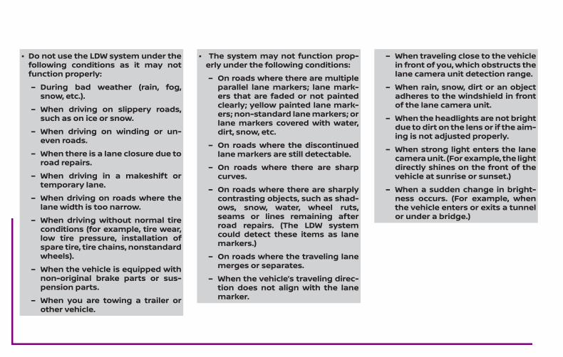
∙ Do not use the LDW system under thefollowing conditions as it may notfunction properly:
– During bad weather (rain, fog,snow, etc.).
– When driving on slippery roads,such as on ice or snow.
– When driving on winding or un-even roads.
– When there is a lane closure due toroad repairs.
– When driving in a makeshift ortemporary lane.
– When driving on roads where thelane width is too narrow.
– When driving without normal tireconditions (for example, tire wear,low tire pressure, installation ofspare tire, tire chains, nonstandardwheels).
– When the vehicle is equipped withnon-original brake parts or sus-pension parts.
– When you are towing a trailer orother vehicle.
∙ The system may not function prop-erly under the following conditions:
– On roads where there are multipleparallel lane markers; lane mark-ers that are faded or not paintedclearly; yellow painted lane mark-ers; non-standard lane markers; orlane markers covered with water,dirt, snow, etc.
– On roads where the discontinuedlane markers are still detectable.
– On roads where there are sharpcurves.
– On roads where there are sharplycontrasting objects, such as shad-ows, snow, water, wheel ruts,seams or lines remaining afterroad repairs. (The LDW systemcould detect these items as lanemarkers.)
– On roads where the traveling lanemerges or separates.
– When the vehicle’s traveling direc-tion does not align with the lanemarker.
– When traveling close to the vehiclein front of you, which obstructs thelane camera unit detection range.
– When rain, snow, dirt or an objectadheres to the windshield in frontof the lane camera unit.
– When the headlights are not brightdue to dirt on the lens or if the aim-ing is not adjusted properly.
– When strong light enters the lanecamera unit. (For example, the lightdirectly shines on the front of thevehicle at sunrise or sunset.)
– When a sudden change in bright-ness occurs. (For example, whenthe vehicle enters or exits a tunnelor under a bridge.)
SYSTEM TEMPORARILYUNAVAILABLEIf the vehicle is parked in direct sunlightunder high temperature conditions (overapproximately 40°C [104°F]) and thenstarted, the LDW system may be deacti-vated automatically and the followingmessage will appear in the vehicle infor-mation display: “Unavailable: High CabinTemperature.”
When the interior temperature is reduced,the LDW system will resume operating au-tomatically.
The LDW system is not designed to warnunder the following conditions:
∙ When you operate the lane change sig-nal and change traveling lanes in thedirection of the signal. (The LDW systemwill become operable again approxi-mately 2 seconds after the lane changesignal is turned off.)
∙ When the vehicle speed lowers to lessthan approximately 70 km/h (45 mph).
After the above conditions have finishedand the necessary operating conditionsare satisfied, the LDW functions will resume.
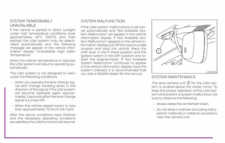
SYSTEM MALFUNCTIONIf the LDW system malfunctions, it will can-cel automatically and “Not Available Sys-tem Malfunction” will appear in the vehicleinformation display. If “Not Available Sys-tem Malfunction” appears in the vehicle in-formation display, pull off the road to a safelocation and stop the vehicle. Place theshift lever in the P (Park) position and theignition switch in the OFF position and re-start the engine/motor. If “Not AvailableSystem Malfunction” continues to appearin the vehicle information display, have thesystem checked. It is recommended thatyou visit a NISSAN dealer for this service.
SYSTEM MAINTENANCEThe lane camera unit �1 for the LDW sys-tem is located above the inside mirror. Tokeep the proper operation of the LDW sys-tem and prevent a system malfunction, besure to observe the following:
∙ Always keep the windshield clean.
∙ Do not attach a sticker (including trans-parent material) or install an accessorynear the camera unit.
LSD3216
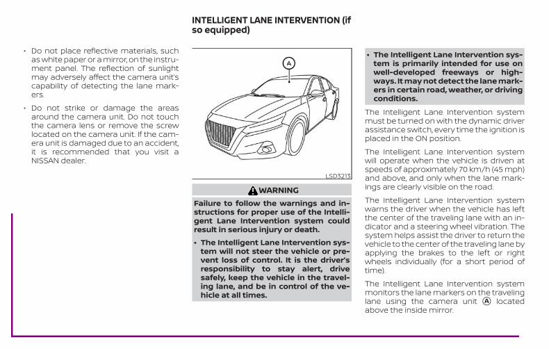
∙ Do not place reflective materials, suchas white paper or a mirror, on the instru-ment panel. The reflection of sunlightmay adversely affect the camera unit’scapability of detecting the lane mark-ers.
∙ Do not strike or damage the areasaround the camera unit. Do not touchthe camera lens or remove the screwlocated on the camera unit. If the cam-era unit is damaged due to an accident,it is recommended that you visit aNISSAN dealer.
WARNINGFailure to follow the warnings and in-structions for proper use of the Intelli-gent Lane Intervention system couldresult in serious injury or death.
∙ The Intelligent Lane Intervention sys-tem will not steer the vehicle or pre-vent loss of control. It is the driver’sresponsibility to stay alert, drivesafely, keep the vehicle in the travel-ing lane, and be in control of the ve-hicle at all times.
∙ The Intelligent Lane Intervention sys-tem is primarily intended for use onwell-developed freeways or high-ways. It may not detect the lane mark-ers in certain road, weather, or drivingconditions.
The Intelligent Lane Intervention systemmust be turned on with the dynamic driverassistance switch, every time the ignition isplaced in the ON position.
The Intelligent Lane Intervention systemwill operate when the vehicle is driven atspeeds of approximately 70 km/h (45 mph)and above, and only when the lane mark-ings are clearly visible on the road.
The Intelligent Lane Intervention systemwarns the driver when the vehicle has leftthe center of the traveling lane with an in-dicator and a steering wheel vibration. Thesystem helps assist the driver to return thevehicle to the center of the traveling lane byapplying the brakes to the left or rightwheels individually (for a short period oftime).
The Intelligent Lane Intervention systemmonitors the lane markers on the travelinglane using the camera unit �A locatedabove the inside mirror.
LSD3213
INTELLIGENT LANE INTERVENTION (ifso equipped)
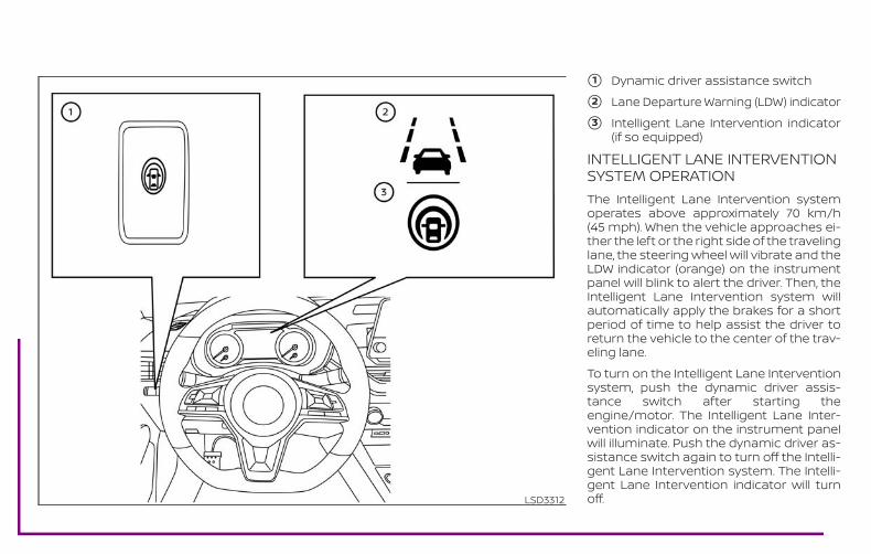
�1 Dynamic driver assistance switch
�2 Lane Departure Warning (LDW) indicator
�3 Intelligent Lane Intervention indicator(if so equipped)
INTELLIGENT LANE INTERVENTIONSYSTEM OPERATIONThe Intelligent Lane Intervention systemoperates above approximately 70 km/h(45 mph). When the vehicle approaches ei-ther the left or the right side of the travelinglane, the steering wheel will vibrate and theLDW indicator (orange) on the instrumentpanel will blink to alert the driver. Then, theIntelligent Lane Intervention system willautomatically apply the brakes for a shortperiod of time to help assist the driver toreturn the vehicle to the center of the trav-eling lane.
To turn on the Intelligent Lane Interventionsystem, push the dynamic driver assis-tance switch after starting theengine/motor. The Intelligent Lane Inter-vention indicator on the instrument panelwill illuminate. Push the dynamic driver as-sistance switch again to turn off the Intelli-gent Lane Intervention system. The Intelli-gent Lane Intervention indicator will turnoff.LSD3312
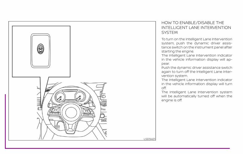
HOW TO ENABLE/DISABLE THEINTELLIGENT LANE INTERVENTIONSYSTEMTo turn on the Intelligent Lane Interventionsystem, push the dynamic driver assis-tance switch on the instrument panel afterstarting the engine.The Intelligent Lane Intervention indicatorin the vehicle information display will ap-pear.Push the dynamic driver assistance switchagain to turn off the Intelligent Lane Inter-vention system.The Intelligent Lane Intervention indicatorin the vehicle information display will turnoff.The Intelligent Lane Intervention systemwill be automatically turned off when theengine is off.
LSD3401
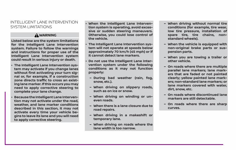
INTELLIGENT LANE INTERVENTIONSYSTEM LIMITATIONS
WARNINGListed below are the system limitationsfor the Intelligent Lane Interventionsystem. Failure to follow the warningsand instructions for proper use of theIntelligent Lane Intervention systemcould result in serious injury or death.
∙ The Intelligent Lane Intervention sys-tem may activate if you change laneswithout first activating your turn sig-nal or, for example, if a constructionzone directs traffic to cross an exist-ing lane marker. If this occurs you mayneed to apply corrective steering tocomplete your lane change.
∙ Because the Intelligent Lane Interven-tion may not activate under the road,weather, and lane marker conditionsdescribed in this section, it may notactivate every time your vehicle be-gins to leave its lane and you will needto apply corrective steering.
∙ When the Intelligent Lane Interven-tion system is operating, avoid exces-sive or sudden steering maneuvers.Otherwise, you could lose control ofthe vehicle.
∙ The Intelligent Lane Intervention sys-tem will not operate at speeds belowapproximately 70 km/h (45 mph) or ifit cannot detect lane markers.
∙ Do not use the Intelligent Lane Inter-vention system under the followingconditions as it may not functionproperly:
– During bad weather (rain, fog,snow, etc.).
– When driving on slippery roads,such as on ice or snow.
– When driving on winding or un-even roads.
– When there is a lane closure due toroad repairs.
– When driving in a makeshift ortemporary lane.
– When driving on roads where thelane width is too narrow.
– When driving without normal tireconditions (for example, tire wear,low tire pressure, installation ofspare tire, tire chains, non-standard wheels).
– When the vehicle is equipped withnon-original brake parts or sus-pension parts.
– When you are towing a trailer orother vehicle.
– On roads where there are multipleparallel lane markers; lane mark-ers that are faded or not paintedclearly; yellow painted lane mark-ers; non-standard lane markers; orlane markers covered with water,dirt, snow, etc.
– On roads where discontinued lanemarkers are still detectable.
– On roads where there are sharpcurves.
– On roads where there are sharplycontrasting objects, such as shad-ows, snow, water, wheel ruts,seams or lines remaining afterroad repairs. (The Intelligent LaneIntervention system could detectthese items as lane markers.)
– On roads where the traveling lanemerges or separates.
– When the vehicle’s traveling direc-tion does not align with the lanemarker.
– When traveling close to the vehiclein front of you, which obstructs thelane camera unit detection range.
– When rain, snow or dirt adheres tothe windshield in front of the lanecamera unit.
– When the headlights are not brightdue to dirt on the lens or if the aim-ing is not adjusted properly.
– When strong light enters the lanecamera unit. (For example, the lightdirectly shines on the front of thevehicle at sunrise or sunset.)
– When a sudden change in bright-ness occurs. (For example, whenthe vehicle enters or exits a tunnelor under a bridge.)
While the Intelligent Lane Intervention sys-tem is operating, you may hear a sound ofbrake operation. This is normal and indi-cates that the Intelligent Lane Interventionsystem is operating properly.
SYSTEM TEMPORARILYUNAVAILABLECondition A:
The warning and assist functions of theIntelligent Lane Intervention system arenot designed to work under the followingconditions:
∙ When you operate the lane change sig-nal and change the traveling lanes inthe direction of the signal. (The Intelli-gent Lane Intervention system will bedeactivated for approximately 2 sec-onds after the lane change signal isturned off.)
∙ When the vehicle speed lowers to lessthan approximately 70 km/h (45 mph).
After the above conditions have finishedand the necessary operating conditionsare satisfied, the warning and assist func-tions will resume.
Condition B:
The assist function of the Intelligent LaneIntervention system is not designed towork under the following conditions (warn-ing is still functional):
∙ When the brake pedal is depressed.
∙ When the steering wheel is turned as faras necessary for the vehicle to changelanes.
∙ When the vehicle is accelerated duringIntelligent Lane Intervention systemoperation.
∙ When the Intelligent Cruise Control (ICC)approach warning occurs.
∙ When the hazard warning flashers areoperated.
∙ When driving on a curve at high speed.
After the above conditions have finishedand the necessary operating conditionsare satisfied, the Intelligent Lane Interven-tion system application of the brakes willresume.
Condition C:
If the following messages appear in thevehicle information display, the IntelligentLane Intervention system will be turned offautomatically.
∙ “Not Available Poor Road Conditions”:When the VDC system (except TractionControl System [TCS] function) or ABSoperates.
∙ “Currently unavailable”:When the VDC system (except TractionControl System [TCS] function) or ABSoperates.
∙ “Currently not available”:When the VDC system is turned off.
Action to take:
When the above conditions no longer exist,turn off the Intelligent Lane Interventionsystem. Push the dynamic driver assis-tance switch again to turn the IntelligentLane Intervention system back on.
Temporary disabled status at high tem-perature:
If the vehicle is parked in direct sunlightunder high temperature conditions (overapproximately 40°C [104°F]) and then theIntelligent Lane Intervention system isturned on, the Intelligent Lane Interventionsystem may be deactivated automaticallyand the following message will appear onthe vehicle information display: “Unavail-able: High Cabin Temperature.” When theinterior temperature is reduced, the sys-tem will resume operating automatically.
SYSTEM MALFUNCTIONIf the Intelligent Lane Intervention systemmalfunctions, it will cancel automatically.The LDW indicator (orange) will illuminate inthe display.
If the LDW indicator (orange) illuminates inthe display, pull off the road to a safe loca-tion and stop the vehicle. Turn theengine/motor off and restart theengine/motor. If the LDW indicator (orange)continues to illuminate, have the IntelligentLane Intervention system checked. It is rec-ommended that you visit a NISSAN dealerfor this service.
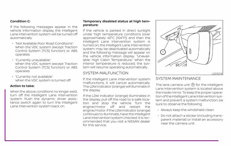
SYSTEM MAINTENANCEThe lane camera unit �1 for the IntelligentLane Intervention system is located abovethe inside mirror. To keep the proper opera-tion of the Intelligent Lane Intervention sys-tem and prevent a system malfunction, besure to observe the following:
∙ Always keep the windshield clean.
∙ Do not attach a sticker (including trans-parent material) or install an accessorynear the camera unit.
LSD3216

∙ Do not place reflective materials, suchas white paper or a mirror, on the instru-ment panel. The reflection of sunlightmay adversely affect the camera unit’scapability of detecting the lane mark-ers.
∙ Do not strike or damage the areasaround the camera unit. Do not touchthe camera lens or remove the screwlocated on the camera unit. If the cam-era unit is damaged due to an accident,it is recommended that you visit aNISSAN dealer.
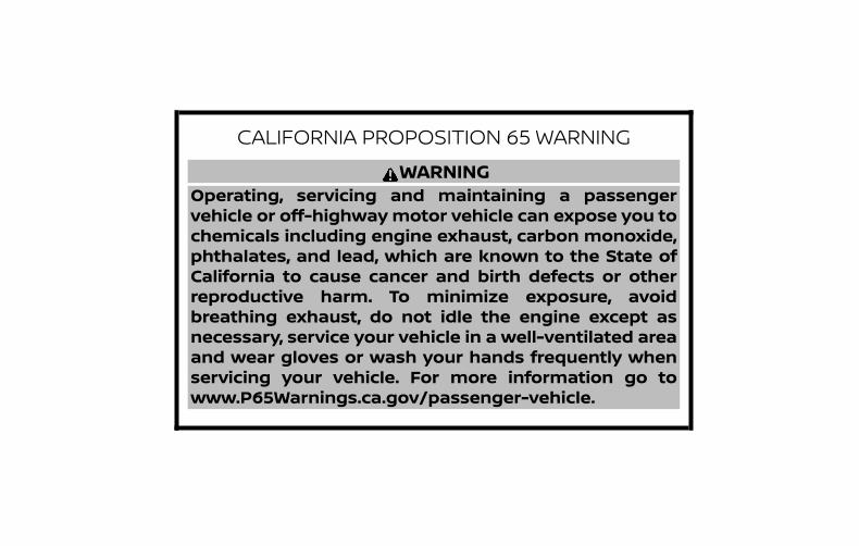
CALIFORNIA PROPOSITION 65 WARNINGWARNING
Operating, servicing and maintaining a passengervehicle or off-highwaymotor vehicle can expose you tochemicals including engine exhaust, carbon monoxide,phthalates, and lead, which are known to the State ofCalifornia to cause cancer and birth defects or otherreproductive harm. To minimize exposure, avoidbreathing exhaust, do not idle the engine except asnecessary, service your vehicle in a well-ventilated areaand wear gloves or wash your hands frequently whenservicing your vehicle. For more information go towww.P65Warnings.ca.gov/passenger-vehicle.
This manual was prepared to help you un-derstand the operation and maintenanceof your vehicle so that you may enjoy manymiles (kilometers) of driving pleasure.Please read through this manual beforeoperating your vehicle.
A separate Warranty Information Book-let explains details about the warrantiescovering your vehicle. The “Maintenanceand schedules” section of this manualexplains details about maintaining andservicing your vehicle. Additionally, aseparate Customer Care/Lemon LawBooklet (U.S. only) will explain how to re-solve any concerns you may have withyour vehicle, and clarify your rights un-der your state’s lemon law.
When you require any service or have anyquestions, a NISSAN dealer will be glad toassist you with the extensive resourcesavailable to them.
In addition to factory-installed options,your vehicle may also be equipped withadditional accessories installed prior to de-livery. It is recommended that you visit aNISSAN dealer for details concerning theparticular accessories with which your ve-hicle is equipped. It is important that youfamiliarize yourself with all disclosures,
warnings, cautions and instructions con-cerning proper use of such accessoriesprior to operating the vehicle and/or ac-cessory. It is recommended that you visit aNISSAN dealer for details concerning theparticular accessories with which your ve-hicle is equipped.
Before driving your vehicle, please read thisOwner’s Manual carefully. This will ensurefamiliarity with controls and maintenancerequirements assisting you in the safe op-eration of your vehicle.
WARNINGIMPORTANT SAFETY INFORMATIONREMINDERS!
Follow these important driving rules tohelp ensure a safe and comfortable tripfor you and your passengers!
∙ NEVER drive under the influence ofalcohol or drugs.
∙ ALWAYS observe posted speed limitsand never drive too fast forconditions.
∙ ALWAYS give your full attention todriving and avoid using vehicle fea-tures or taking other actions thatcould distract you.
∙ ALWAYS use your seat belts andappropriate child restraint systems.Preteen children should be seated inthe rear seat.
FOREWORD READ FIRST—THEN DRIVE SAFELY
∙ ALWAYS provide information aboutthe proper use of vehicle safety fea-tures to all occupants of the vehicle.
∙ ALWAYS review this Owner’s Manualfor important safety information.
MODIFICATION OF YOUR VEHICLEThis vehicle should not be modified.Modification could affect itsperformance, safety, emissions or du-rability and may even violate govern-mental regulations. In addition, dam-age or performance problemsresulting from modifications may notbe covered under NISSAN warranties.
WARNINGInstalling an aftermarket On-Board Di-agnostic (OBD) plug-in device that usesthe port during normal driving, for ex-ample remote insurance companymonitoring, remote vehicle diagnostics,telematics or engine reprogramming,may cause interference or damage tovehicle systems. We do not recommendor endorse the use of any aftermarketOBD plug-in devices, unless specificallyapproved by NISSAN. The vehicle war-ranty may not cover damage caused byany aftermarket plug-in device.
This manual includes information for all fea-tures and equipment available on this model.Features and equipment in your vehicle mayvary depending on model, trim level, optionsselected, order, date of production, region oravailability. Therefore, you may find informa-tion about features or equipment that arenot included or installed on your vehicle.
All information, specifications and illustra-tions in this manual are those in effect at thetime of printing. NISSAN reserves the right tochange specifications, performance, designor component suppliers without notice andwithout obligation. From time to time,NISSAN may update or revise this manual toprovide Owners with the most accurate in-formation currently available. Please care-fully read and retain with this manual all re-vision updates sent to you by NISSAN toensure you have access to accurate and up-to-date information regarding your vehicle.Current versions of vehicle Owner’s Manualsand any updates can also be found in theOwner section of the NISSAN website athttps://owners.nissanusa.com/nowners/navigation/manualsGuide. If you havequestions concerning any information inyour Owner’s Manual, contact NISSAN Con-sumer Affairs. For contact information, re-fer to the NISSAN CUSTOMER CARE PRO-GRAM page in this Owner’s Manual.
WHEN READING THE MANUAL
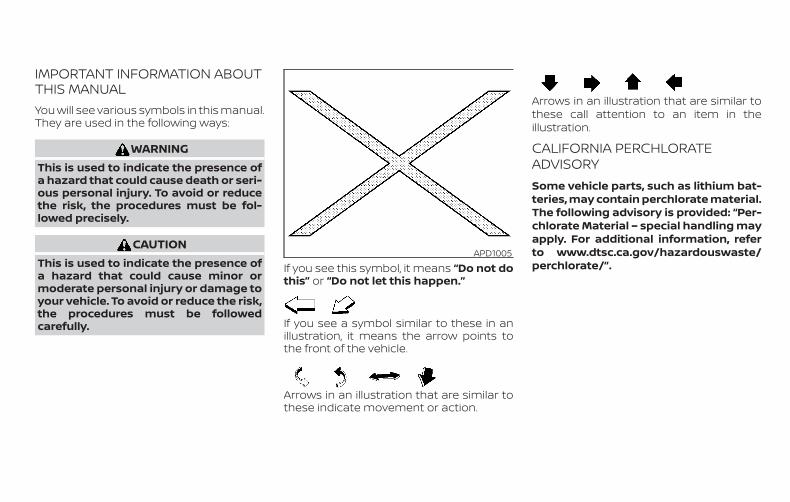
IMPORTANT INFORMATION ABOUTTHIS MANUALYou will see various symbols in this manual.They are used in the following ways:
WARNINGThis is used to indicate the presence ofa hazard that could cause death or seri-ous personal injury. To avoid or reducethe risk, the procedures must be fol-lowed precisely.
CAUTIONThis is used to indicate the presence ofa hazard that could cause minor ormoderate personal injury or damage toyour vehicle. To avoid or reduce the risk,the procedures must be followedcarefully.
If you see this symbol, it means “Do not dothis” or “Do not let this happen.”
If you see a symbol similar to these in anillustration, it means the arrow points tothe front of the vehicle.
Arrows in an illustration that are similar tothese indicate movement or action.
Arrows in an illustration that are similar tothese call attention to an item in theillustration.
CALIFORNIA PERCHLORATEADVISORYSome vehicle parts, such as lithium bat-teries, may contain perchlorate material.The following advisory is provided: “Per-chlorate Material – special handling mayapply. For additional information, referto www.dtsc.ca.gov/hazardouswaste/perchlorate/”.
APD1005

SiriusXM® servicesrequire a subscrip-tion after trialperiod and aresold separately oras a package.The satellite ser-vice is availableonly in the 48 con-tiguous USA andDC. SiriusXM®satellite service isalso available inCanada; seewww.siriusxm.ca.
© 2019 NISSAN NORTH AMERICA, INC.
All rights reserved. No part of this Owner’sManual may be reproduced or stored ina retrieval system, or transmitted inany form, or by any means, electronic,mechanical, photocopying, recording orotherwise, without the prior written per-mission of Nissan North America, Inc.
NISSAN CARES . . .
Both NISSAN and your NISSAN dealer are dedicated to serving all your automotive needs. Your satisfaction with your vehicle and yourNISSAN dealer are our primary concerns. Your NISSAN dealer is always available to assist you with all your automobile sales and serviceneeds.However, if there is something that yourNISSAN dealer cannot assist you with oryou would like to provide NISSAN directlywith comments or questions, please con-tact the NISSAN Consumer Affairs Depart-ment using our toll-free number:
For U.S. customers1-800-NISSAN-1(1-800-647-7261)
For Canadian customers1-800-387-0122
The Consumer Affairs Department will askfor the following information:
– Your name, address, and telephonenumber
– Vehicle identification number (attachedto the top of the instrument panel on thedriver’s side)
– Date of purchase
– Current odometer reading
– Your NISSAN dealer’s name
– Your comments or questions
OR
You can write to NISSAN with the informa-tion at:
For U.S. customersNissan North America, Inc.Consumer Affairs DepartmentP.O. Box 685003Franklin, TN 37068-5003or via e-mail at:[email protected]
For Canadian customersNissan Canada Inc.5290 Orbitor DriveMississauga, Ontario L4W 4Z5or via e-mail at:[email protected]
If you prefer, visit us at:www.nissanusa.com (for U.S. customers)orwww.nissan.ca (for Canadian customers)
We appreciate your interest in NISSAN and thank you for buying a quality NISSAN vehicle.
NISSAN CUSTOMER CARE PROGRAM

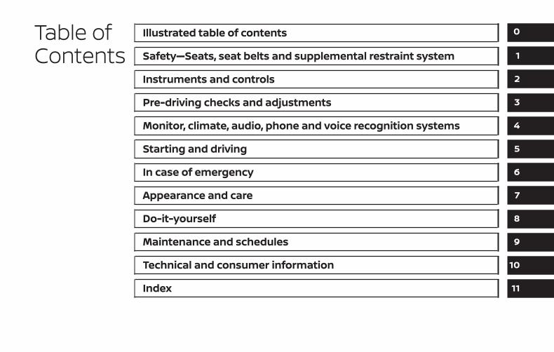
Table ofContents
Illustrated table of contents
Safety—Seats, seat belts and supplemental restraint system
Instruments and controls
Pre-driving checks and adjustments
Monitor, climate, audio, phone and voice recognition systems
Starting and driving
In case of emergency
Appearance and care
Do-it-yourself
Maintenance and schedules
Technical and consumer information
Index
0
1
2
3
4
5
6
7
8
9
10
11

0 Illustrated table of contents
Air bags, seat belts and child restraints . . . . . . . . . . 0-2Exterior front . . . . . . . . . . . . . . . . . . . . . . . . . . . . . . . . . . . . 0-3Exterior rear . . . . . . . . . . . . . . . . . . . . . . . . . . . . . . . . . . . . . 0-4Passenger compartment. . . . . . . . . . . . . . . . . . . . . . . . 0-5
Instrument panel . . . . . . . . . . . . . . . . . . . . . . . . . . . . . . . . 0-6Engine compartment check locations . . . . . . . . . . . 0-8Warning and indicator lights . . . . . . . . . . . . . . . . . . . . 0-10
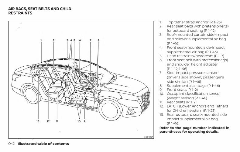
1. Top tether strap anchor (P. 1-23)2. Rear seat belts with pretensioner(s)
for outboard seating (P. 1-12)3. Roof-mounted curtain side-impact
and rollover supplemental air bag(P. 1-46)
4. Front seat-mounted side-impactsupplemental air bag (P. 1-46)
5. Head restraints/headrests (P. 1-7)6. Front seat belt with pretensioner(s)
and shoulder height adjuster(P. 1-12, 1-46)
7. Side-impact pressure sensor(driver’s side shown; passenger’sside similar) (P. 1-46)
8. Supplemental air bags (P. 1-46)9. Front seats (P. 1-2)10. Occupant classification sensor
(weight sensor) (P. 1-46)11. Rear seats (P. 1-2)12. LATCH (Lower Anchors and Tethers
for CHildren) system (P. 1-23)13. Rear outboard seat-mounted side
impact supplemental air bag(P. 1-46)
Refer to the page number indicated inparentheses for operating details.
LII2583
AIR BAGS, SEAT BELTS AND CHILDRESTRAINTS
0-2 Illustrated table of contents
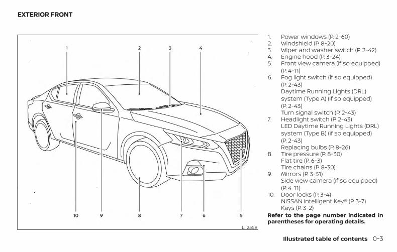
1. Power windows (P. 2-60)2. Windshield (P. 8-20)3. Wiper and washer switch (P. 2-42)4. Engine hood (P. 3-24)5. Front view camera (if so equipped)
(P. 4-11)6. Fog light switch (if so equipped)
(P. 2-43)Daytime Running Lights (DRL)system (Type A) (if so equipped)(P. 2-43)Turn signal switch (P. 2-43)
7. Headlight switch (P. 2-43)LED Daytime Running Lights (DRL)system (Type B) (if so equipped)(P. 2-43)Replacing bulbs (P. 8-26)
8. Tire pressure (P. 8-30)Flat tire (P. 6-3)Tire chains (P. 8-30)
9. Mirrors (P. 3-31)Side view camera (if so equipped)(P. 4-11)
10. Door locks (P. 3-4)NISSAN Intelligent Key® (P. 3-7)Keys (P. 3-2)
Refer to the page number indicated inparentheses for operating details.
LII2559
EXTERIOR FRONT
Illustrated table of contents 0-3
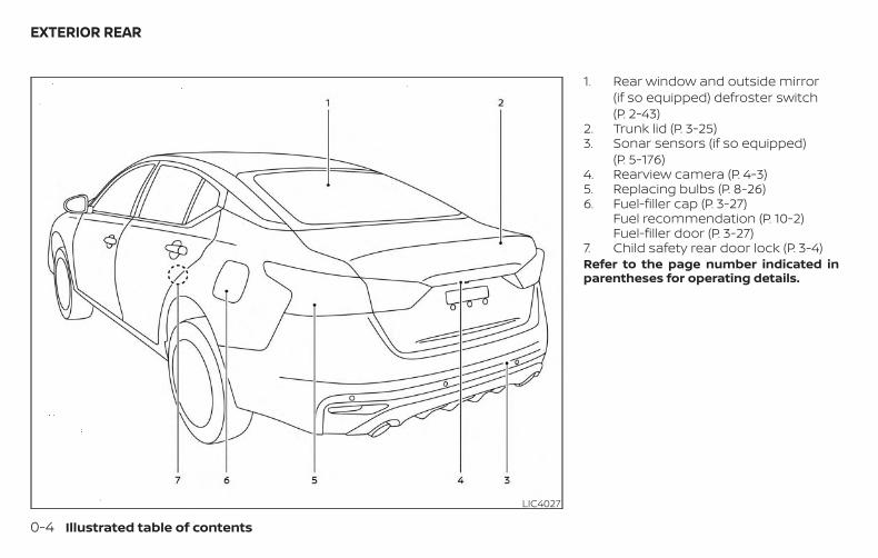
1. Rear window and outside mirror(if so equipped) defroster switch(P. 2-43)
2. Trunk lid (P. 3-25)3. Sonar sensors (if so equipped)
(P. 5-176)4. Rearview camera (P. 4-3)5. Replacing bulbs (P. 8-26)6. Fuel-filler cap (P. 3-27)
Fuel recommendation (P. 10-2)Fuel-filler door (P. 3-27)
7. Child safety rear door lock (P. 3-4)Refer to the page number indicated inparentheses for operating details.
LIC4027
EXTERIOR REAR
0-4 Illustrated table of contents
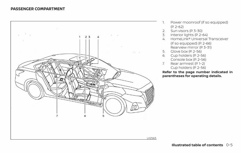
1. Power moonroof (if so equipped)(P. 2-62)
2. Sun visors (P. 3-30)3. Interior lights (P. 2-64)4. HomeLink® Universal Transceiver
(if so equipped) (P. 2-66)Rearview mirror (P. 3-31)
5. Glove box (P. 2-56)6. Cup holders (P. 2-56)
Console box (P. 2-56)7. Rear armrest (P. 1-2)
Cup holders (P. 2-56)Refer to the page number indicated inparentheses for operating details.
LII2563
PASSENGER COMPARTMENT
Illustrated table of contents 0-5
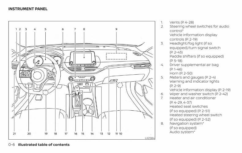
1. Vents (P. 4-28)2. Steering wheel switches for audio
control*Vehicle information displaycontrols (P. 2-19)
3. Headlight/fog light (if soequipped)/turn signal switch(P. 2-43)Paddle shifters (if so equipped)(P. 5-18)
4. Driver supplemental air bag(P. 1-46)Horn (P. 2-50)
5. Meters and gauges (P. 2-4)Warning and indicator lights(P. 2-9)Vehicle information display (P. 2-19)
6. Wiper and washer switch (P. 2-42)7. Heater and air conditioner
(P. 4-29, 4-37)Heated seat switches(if so equipped) (P. 2-51)Heated steering wheel switch(if so equipped) (P. 2-52)
8. Navigation system*(if so equipped)Audio system*
LII2584
INSTRUMENT PANEL
0-6 Illustrated table of contents
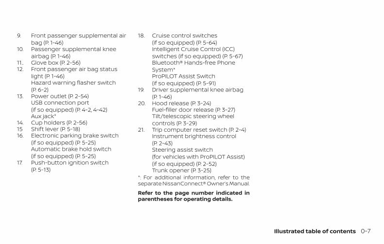
9. Front passenger supplemental airbag (P. 1-46)
10. Passenger supplemental kneeairbag (P. 1-46)
11.. Glove box (P. 2-56)12. Front passenger air bag status
light (P. 1-46)Hazard warning flasher switch(P. 6-2)
13. Power outlet (P. 2-54)USB connection port(if so equipped) (P. 4-2, 4-42)Aux jack*
14. Cup holders (P. 2-56)15 Shift lever (P. 5-18)16. Electronic parking brake switch
(if so equipped) (P. 5-25)Automatic brake hold switch(if so equipped) (P. 5-25)
17. Push-button ignition switch(P. 5-13)
18. Cruise control switches(if so equipped) (P. 5-64)Intelligent Cruise Control (ICC)switches (if so equipped) (P. 5-67)Bluetooth® Hands-free PhoneSystem*ProPILOT Assist Switch(if so equipped) (P. 5-91)
19. Driver supplemental knee airbag(P. 1-46)
20. Hood release (P. 3-24)Fuel-filler door release (P. 3-27)Tilt/telescopic steering wheelcontrols (P. 3-29)
21. Trip computer reset switch (P. 2-4)Instrument brightness control(P. 2-43)Steering assist switch(for vehicles with ProPILOT Assist)(if so equipped) (P. 2-52)Trunk opener (P. 3-25)
*: For additional information, refer to theseparate NissanConnect® Owner’s Manual.
Refer to the page number indicated inparentheses for operating details.
Illustrated table of contents 0-7
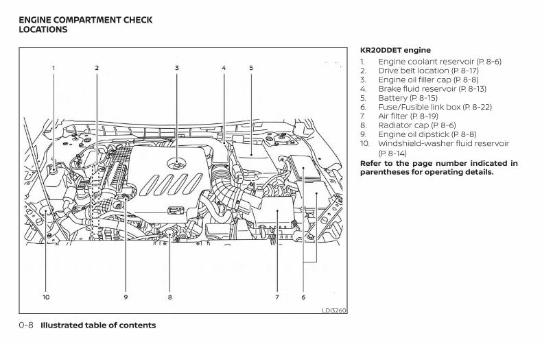
KR20DDET engine1. Engine coolant reservoir (P. 8-6)2. Drive belt location (P. 8-17)3. Engine oil filler cap (P. 8-8)4. Brake fluid reservoir (P. 8-13)5. Battery (P. 8-15)6. Fuse/Fusible link box (P. 8-22)7. Air filter (P. 8-19)8. Radiator cap (P. 8-6)9. Engine oil dipstick (P. 8-8)10. Windshield-washer fluid reservoir
(P. 8-14)Refer to the page number indicated inparentheses for operating details.
LDI3260
ENGINE COMPARTMENT CHECKLOCATIONS
0-8 Illustrated table of contents
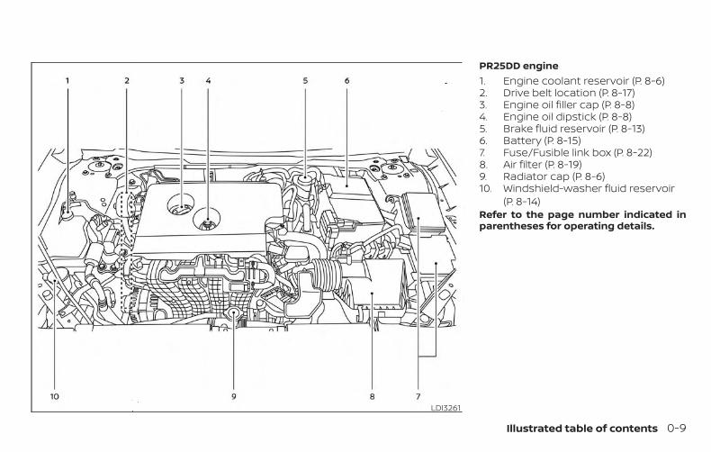
PR25DD engine1. Engine coolant reservoir (P. 8-6)2. Drive belt location (P. 8-17)3. Engine oil filler cap (P. 8-8)4. Engine oil dipstick (P. 8-8)5. Brake fluid reservoir (P. 8-13)6. Battery (P. 8-15)7. Fuse/Fusible link box (P. 8-22)8. Air filter (P. 8-19)9. Radiator cap (P. 8-6)10. Windshield-washer fluid reservoir
(P. 8-14)Refer to the page number indicated inparentheses for operating details.
LDI3261
Illustrated table of contents 0-9
Warninglight
Name Page
or
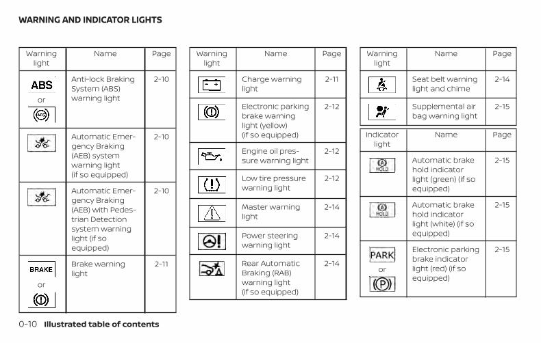
Anti-lock BrakingSystem (ABS)warning light
2-10
Automatic Emer-gency Braking(AEB) systemwarning light(if so equipped)
2-10
Automatic Emer-gency Braking(AEB) with Pedes-trian Detectionsystem warninglight (if soequipped)
2-10
or
Brake warninglight
2-11
Warninglight
Name Page
Charge warninglight
2-11
Electronic parkingbrake warninglight (yellow)(if so equipped)
2-12
Engine oil pres-sure warning light
2-12
Low tire pressurewarning light
2-12
Master warninglight
2-14
Power steeringwarning light
2-14
Rear AutomaticBraking (RAB)warning light(if so equipped)
2-14
Warninglight
Name Page
Seat belt warninglight and chime
2-14
Supplemental airbag warning light
2-15
Indicatorlight
Name Page
Automatic brakehold indicatorlight (green) (if soequipped)
2-15
Automatic brakehold indicatorlight (white) (if soequipped)
2-15
or
Electronic parkingbrake indicatorlight (red) (if soequipped)
2-15
WARNING AND INDICATOR LIGHTS
0-10 Illustrated table of contents
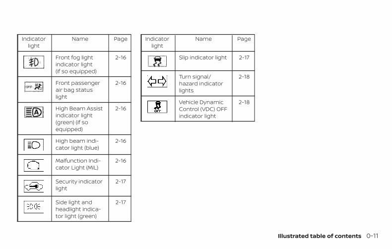
Indicatorlight
Name Page
Front fog lightindicator light(if so equipped)
2-16
Front passengerair bag statuslight
2-16
High Beam Assistindicator light(green) (if soequipped)
2-16
High beam indi-cator light (blue)
2-16
Malfunction Indi-cator Light (MIL)
2-16
Security indicatorlight
2-17
Side light andheadlight indica-tor light (green)
2-17
Indicatorlight
Name Page
Slip indicator light 2-17
Turn signal/hazard indicatorlights
2-18
Vehicle DynamicControl (VDC) OFFindicator light
2-18
Illustrated table of contents 0-11

MEMO
0-12 Illustrated table of contents
1 Safety—Seats, seat belts andsupplemental restraint system
Seats . . . . . . . . . . . . . . . . . . . . . . . . . . . . . . . . . . . . . . . . . . . . 1-2Front manual seat adjustment(if so equipped for passenger’s seat). . . . . . . . . . .1-3Front power seat adjustment(for driver’s seat and if so equipped forpassenger’s seat). . . . . . . . . . . . . . . . . . . . . . . . . . . . . 1-4Folding rear seat . . . . . . . . . . . . . . . . . . . . . . . . . . . . . 1-5Center armrest . . . . . . . . . . . . . . . . . . . . . . . . . . . . . . . .1-7
Head restraints/headrests . . . . . . . . . . . . . . . . . . . . . . .1-7Adjustable head restraint/headrestcomponents . . . . . . . . . . . . . . . . . . . . . . . . . . . . . . . . . 1-8Non-adjustable head restraint/headrest components. . . . . . . . . . . . . . . . . . . . . . . . 1-9Remove . . . . . . . . . . . . . . . . . . . . . . . . . . . . . . . . . . . . . . 1-9Install. . . . . . . . . . . . . . . . . . . . . . . . . . . . . . . . . . . . . . . . .1-10Adjust . . . . . . . . . . . . . . . . . . . . . . . . . . . . . . . . . . . . . . . .1-10
Seat belts . . . . . . . . . . . . . . . . . . . . . . . . . . . . . . . . . . . . . . .1-12Precautions on seat belt usage. . . . . . . . . . . . . . .1-12Seat belt warning light and chime . . . . . . . . . . . .1-14Pregnant women. . . . . . . . . . . . . . . . . . . . . . . . . . . . .1-15Injured persons. . . . . . . . . . . . . . . . . . . . . . . . . . . . . . .1-15Three-point type seat belt withretractor . . . . . . . . . . . . . . . . . . . . . . . . . . . . . . . . . . . . .1-15
Seat belt extenders. . . . . . . . . . . . . . . . . . . . . . . . . . 1-20Seat belt maintenance . . . . . . . . . . . . . . . . . . . . . . 1-20
Child safety. . . . . . . . . . . . . . . . . . . . . . . . . . . . . . . . . . . . . .1-21Infants . . . . . . . . . . . . . . . . . . . . . . . . . . . . . . . . . . . . . . 1-22Small children . . . . . . . . . . . . . . . . . . . . . . . . . . . . . . . 1-22Larger children . . . . . . . . . . . . . . . . . . . . . . . . . . . . . . 1-22
Child restraints . . . . . . . . . . . . . . . . . . . . . . . . . . . . . . . . . 1-23Precautions on child restraints . . . . . . . . . . . . . . 1-23LATCH (Lower Anchors and Tethers forCHildren) system . . . . . . . . . . . . . . . . . . . . . . . . . . . . 1-26Rear-facing child restraint installationusing LATCH. . . . . . . . . . . . . . . . . . . . . . . . . . . . . . . . . 1-28Rear-facing child restraint installationusing the seat belts . . . . . . . . . . . . . . . . . . . . . . . . . .1-31Forward-facing child restraintinstallation using LATCH . . . . . . . . . . . . . . . . . . . . . 1-34Forward-facing child restraintinstallation using the seat belts. . . . . . . . . . . . . . 1-38Booster seats . . . . . . . . . . . . . . . . . . . . . . . . . . . . . . . 1-42
Supplemental Restraint System (SRS). . . . . . . . . . . 1-46Precautions on SRS. . . . . . . . . . . . . . . . . . . . . . . . . . 1-46Supplemental air bag warning labels . . . . . . . . 1-66Supplemental air bag warning light. . . . . . . . . . 1-66
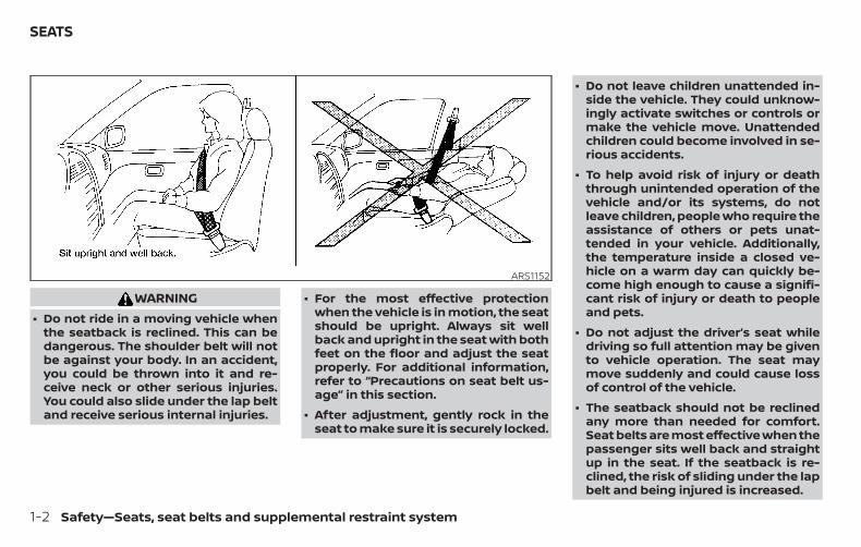
WARNING∙ Do not ride in a moving vehicle when
the seatback is reclined. This can bedangerous. The shoulder belt will notbe against your body. In an accident,you could be thrown into it and re-ceive neck or other serious injuries.You could also slide under the lap beltand receive serious internal injuries.
∙ For the most effective protectionwhen the vehicle is in motion, the seatshould be upright. Always sit wellback and upright in the seat with bothfeet on the floor and adjust the seatproperly. For additional information,refer to “Precautions on seat belt us-age” in this section.
∙ After adjustment, gently rock in theseat to make sure it is securely locked.
∙ Do not leave children unattended in-side the vehicle. They could unknow-ingly activate switches or controls ormake the vehicle move. Unattendedchildren could become involved in se-rious accidents.
∙ To help avoid risk of injury or deaththrough unintended operation of thevehicle and/or its systems, do notleave children, people who require theassistance of others or pets unat-tended in your vehicle. Additionally,the temperature inside a closed ve-hicle on a warm day can quickly be-come high enough to cause a signifi-cant risk of injury or death to peopleand pets.
∙ Do not adjust the driver’s seat whiledriving so full attention may be givento vehicle operation. The seat maymove suddenly and could cause lossof control of the vehicle.
∙ The seatback should not be reclinedany more than needed for comfort.Seat belts are most effective when thepassenger sits well back and straightup in the seat. If the seatback is re-clined, the risk of sliding under the lapbelt and being injured is increased.
ARS1152
SEATS
1-2 Safety—Seats, seat belts and supplemental restraint system
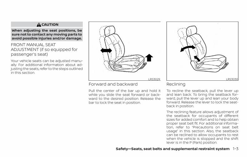
CAUTIONWhen adjusting the seat positions, besure not to contact any moving parts toavoid possible injuries and/or damage.
FRONT MANUAL SEATADJUSTMENT (if so equipped forpassenger’s seat)Your vehicle seats can be adjusted manu-ally. For additional information about ad-justing the seats, refer to the steps outlinedin this section.
Forward and backwardPull the center of the bar up and hold itwhile you slide the seat forward or back-ward to the desired position. Release thebar to lock the seat in position.
RecliningTo recline the seatback, pull the lever upand lean back. To bring the seatback for-ward, pull the lever up and lean your bodyforward. Release the lever to lock the seat-back in position.
The reclining feature allows adjustment ofthe seatback for occupants of differentsizes for added comfort and to help obtainproper seat belt fit. For additional informa-tion, refer to “Precautions on seat beltusage” in this section. Also, the seatbackcan be reclined to allow occupants to restwhen the vehicle is stopped and the shiftlever is in the P (Park) position.
LRS3029 LRS3030
Safety—Seats, seat belts and supplemental restraint system 1-3
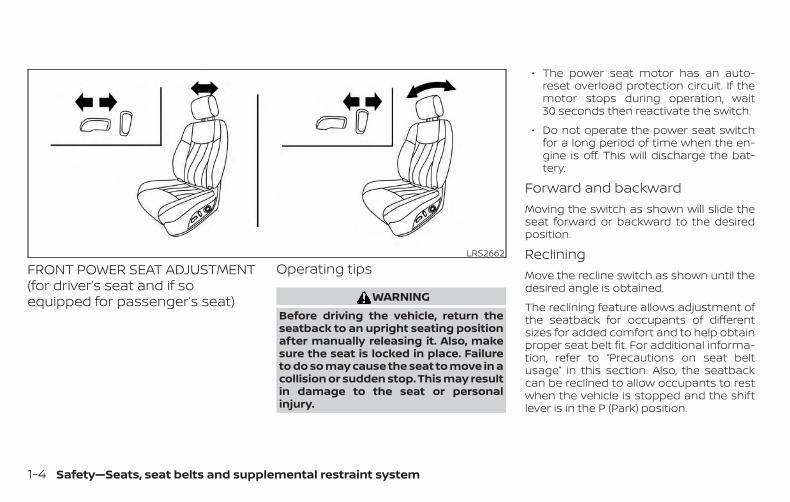
FRONT POWER SEAT ADJUSTMENT(for driver’s seat and if soequipped for passenger’s seat)
Operating tips
WARNINGBefore driving the vehicle, return theseatback to an upright seating positionafter manually releasing it. Also, makesure the seat is locked in place. Failureto do so may cause the seat to move in acollision or sudden stop. This may resultin damage to the seat or personalinjury.
∙ The power seat motor has an auto-reset overload protection circuit. If themotor stops during operation, wait30 seconds then reactivate the switch.
∙ Do not operate the power seat switchfor a long period of time when the en-gine is off. This will discharge the bat-tery.
Forward and backwardMoving the switch as shown will slide theseat forward or backward to the desiredposition.
RecliningMove the recline switch as shown until thedesired angle is obtained.
The reclining feature allows adjustment ofthe seatback for occupants of differentsizes for added comfort and to help obtainproper seat belt fit. For additional informa-tion, refer to “Precautions on seat beltusage” in this section. Also, the seatbackcan be reclined to allow occupants to restwhen the vehicle is stopped and the shiftlever is in the P (Park) position.
LRS2662
1-4 Safety—Seats, seat belts and supplemental restraint system
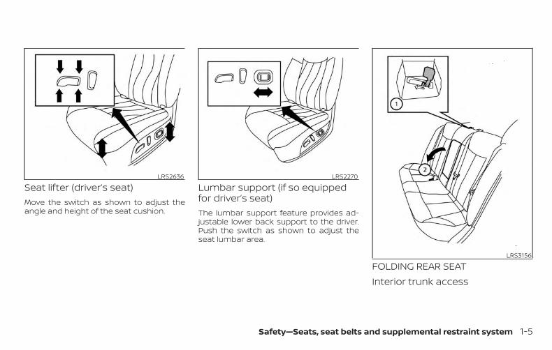
Seat lifter (driver’s seat)Move the switch as shown to adjust theangle and height of the seat cushion.
Lumbar support (if so equippedfor driver’s seat)The lumbar support feature provides ad-justable lower back support to the driver.Push the switch as shown to adjust theseat lumbar area.
FOLDING REAR SEATInterior trunk access
LRS2636 LRS2270
LRS3156
Safety—Seats, seat belts and supplemental restraint system 1-5
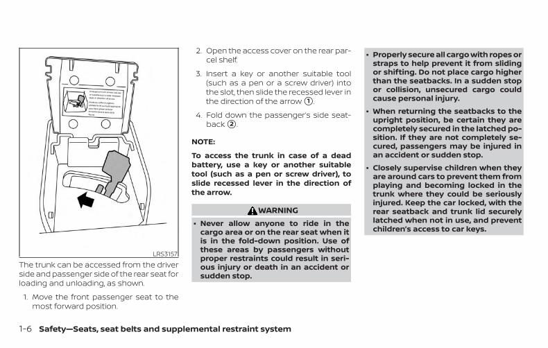
The trunk can be accessed from the driverside and passenger side of the rear seat forloading and unloading, as shown.
1. Move the front passenger seat to themost forward position.
2. Open the access cover on the rear par-cel shelf.
3. Insert a key or another suitable tool(such as a pen or a screw driver) intothe slot, then slide the recessed lever inthe direction of the arrow �1 .
4. Fold down the passenger’s side seat-back �2 .
NOTE:
To access the trunk in case of a deadbattery, use a key or another suitabletool (such as a pen or screw driver), toslide recessed lever in the direction ofthe arrow.
WARNING∙ Never allow anyone to ride in the
cargo area or on the rear seat when itis in the fold-down position. Use ofthese areas by passengers withoutproper restraints could result in seri-ous injury or death in an accident orsudden stop.
∙ Properly secure all cargo with ropes orstraps to help prevent it from slidingor shifting. Do not place cargo higherthan the seatbacks. In a sudden stopor collision, unsecured cargo couldcause personal injury.
∙ When returning the seatbacks to theupright position, be certain they arecompletely secured in the latched po-sition. If they are not completely se-cured, passengers may be injured inan accident or sudden stop.
∙ Closely supervise children when theyare around cars to prevent them fromplaying and becoming locked in thetrunk where they could be seriouslyinjured. Keep the car locked, with therear seatback and trunk lid securelylatched when not in use, and preventchildren’s access to car keys.
LRS3157
1-6 Safety—Seats, seat belts and supplemental restraint system
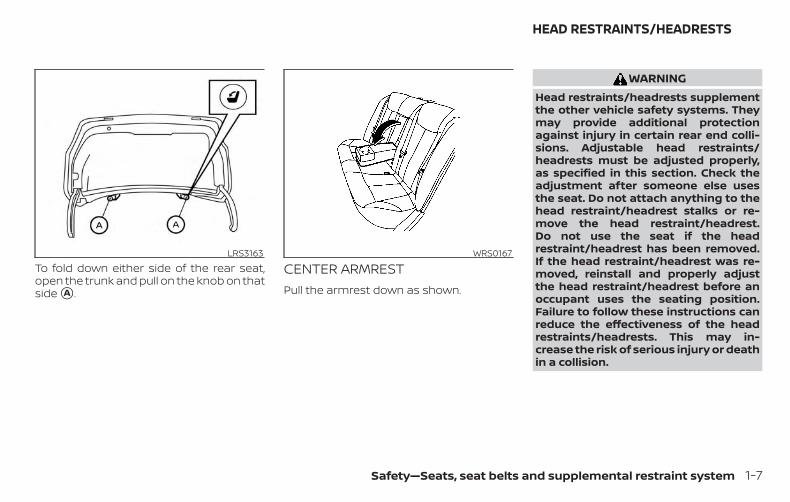
To fold down either side of the rear seat,open the trunk and pull on the knob on thatside �A .
CENTER ARMRESTPull the armrest down as shown.
WARNINGHead restraints/headrests supplementthe other vehicle safety systems. Theymay provide additional protectionagainst injury in certain rear end colli-sions. Adjustable head restraints/headrests must be adjusted properly,as specified in this section. Check theadjustment after someone else usesthe seat. Do not attach anything to thehead restraint/headrest stalks or re-move the head restraint/headrest.Do not use the seat if the headrestraint/headrest has been removed.If the head restraint/headrest was re-moved, reinstall and properly adjustthe head restraint/headrest before anoccupant uses the seating position.Failure to follow these instructions canreduce the effectiveness of the headrestraints/headrests. This may in-crease the risk of serious injury or deathin a collision.
LRS3163 WRS0167
HEAD RESTRAINTS/HEADRESTS
Safety—Seats, seat belts and supplemental restraint system 1-7
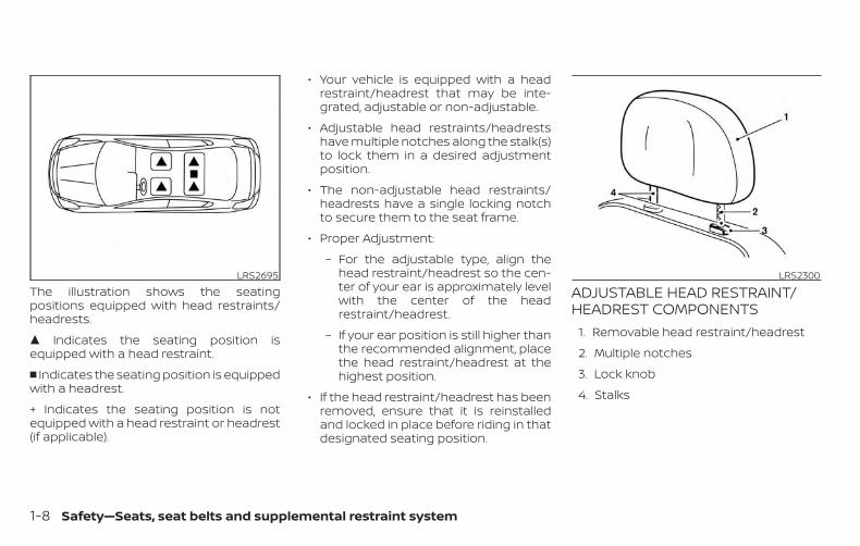
The illustration shows the seatingpositions equipped with head restraints/headrests.
� Indicates the seating position isequipped with a head restraint.
� Indicates the seating position is equippedwith a headrest.
+ Indicates the seating position is notequipped with a head restraint or headrest(if applicable).
∙ Your vehicle is equipped with a headrestraint/headrest that may be inte-grated, adjustable or non-adjustable.
∙ Adjustable head restraints/headrestshave multiple notches along the stalk(s)to lock them in a desired adjustmentposition.
∙ The non-adjustable head restraints/headrests have a single locking notchto secure them to the seat frame.
∙ Proper Adjustment:
– For the adjustable type, align thehead restraint/headrest so the cen-ter of your ear is approximately levelwith the center of the headrestraint/headrest.
– If your ear position is still higher thanthe recommended alignment, placethe head restraint/headrest at thehighest position.
∙ If the head restraint/headrest has beenremoved, ensure that it is reinstalledand locked in place before riding in thatdesignated seating position.
ADJUSTABLE HEAD RESTRAINT/HEADREST COMPONENTS
1. Removable head restraint/headrest
2. Multiple notches
3. Lock knob
4. Stalks
LRS2695 LRS2300
1-8 Safety—Seats, seat belts and supplemental restraint system
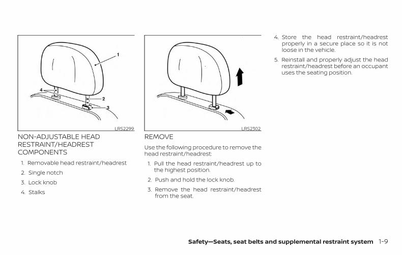
NON-ADJUSTABLE HEADRESTRAINT/HEADRESTCOMPONENTS
1. Removable head restraint/headrest
2. Single notch
3. Lock knob
4. Stalks
REMOVEUse the following procedure to remove thehead restraint/headrest:
1. Pull the head restraint/headrest up tothe highest position.
2. Push and hold the lock knob.
3. Remove the head restraint/headrestfrom the seat.
4. Store the head restraint/headrestproperly in a secure place so it is notloose in the vehicle.
5. Reinstall and properly adjust the headrestraint/headrest before an occupantuses the seating position.
LRS2299 LRS2302
Safety—Seats, seat belts and supplemental restraint system 1-9
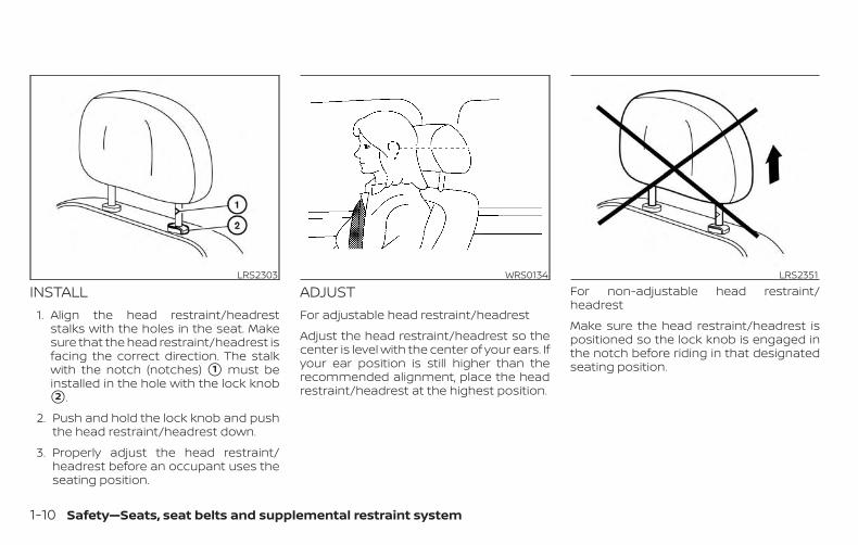
INSTALL1. Align the head restraint/headrest
stalks with the holes in the seat. Makesure that the head restraint/headrest isfacing the correct direction. The stalkwith the notch (notches) �1 must beinstalled in the hole with the lock knob�2 .
2. Push and hold the lock knob and pushthe head restraint/headrest down.
3. Properly adjust the head restraint/headrest before an occupant uses theseating position.
ADJUSTFor adjustable head restraint/headrest
Adjust the head restraint/headrest so thecenter is level with the center of your ears. Ifyour ear position is still higher than therecommended alignment, place the headrestraint/headrest at the highest position.
For non-adjustable head restraint/headrest
Make sure the head restraint/headrest ispositioned so the lock knob is engaged inthe notch before riding in that designatedseating position.
LRS2303 WRS0134 LRS2351
1-10 Safety—Seats, seat belts and supplemental restraint system
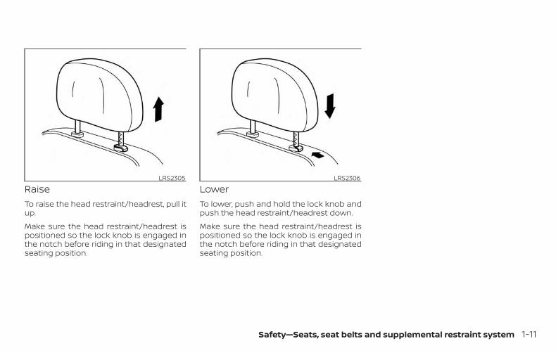
RaiseTo raise the head restraint/headrest, pull itup.
Make sure the head restraint/headrest ispositioned so the lock knob is engaged inthe notch before riding in that designatedseating position.
LowerTo lower, push and hold the lock knob andpush the head restraint/headrest down.
Make sure the head restraint/headrest ispositioned so the lock knob is engaged inthe notch before riding in that designatedseating position.
LRS2305 LRS2306
Safety—Seats, seat belts and supplemental restraint system 1-11
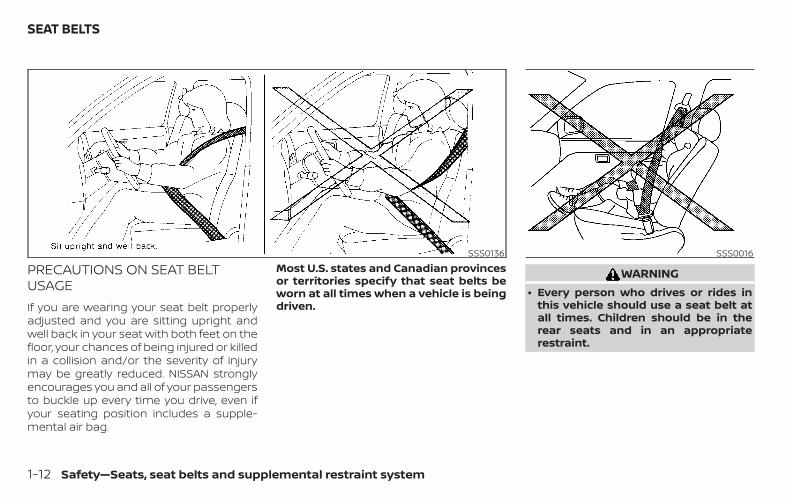
PRECAUTIONS ON SEAT BELTUSAGEIf you are wearing your seat belt properlyadjusted and you are sitting upright andwell back in your seat with both feet on thefloor, your chances of being injured or killedin a collision and/or the severity of injurymay be greatly reduced. NISSAN stronglyencourages you and all of your passengersto buckle up every time you drive, even ifyour seating position includes a supple-mental air bag.
Most U.S. states and Canadian provincesor territories specify that seat belts beworn at all times when a vehicle is beingdriven.
WARNING∙ Every person who drives or rides in
this vehicle should use a seat belt atall times. Children should be in therear seats and in an appropriaterestraint.
SSS0136 SSS0016
SEAT BELTS
1-12 Safety—Seats, seat belts and supplemental restraint system
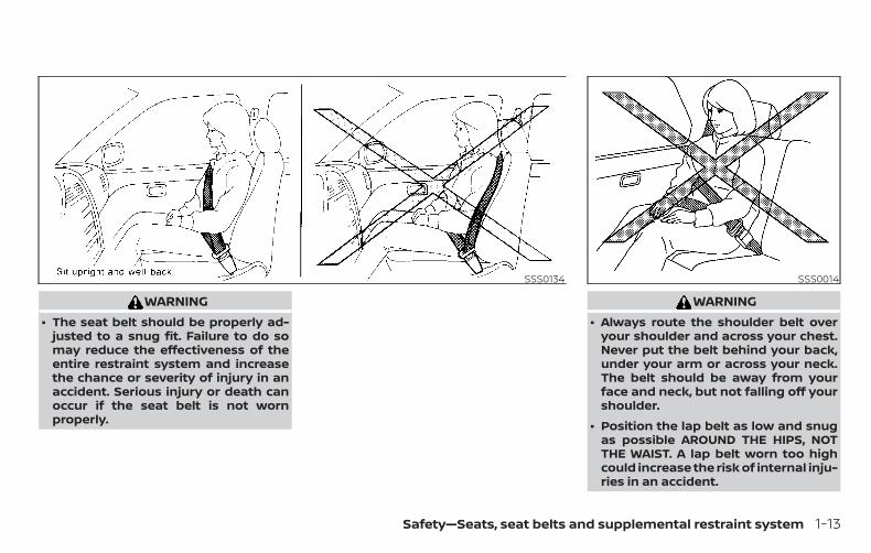
WARNING∙ The seat belt should be properly ad-
justed to a snug fit. Failure to do somay reduce the effectiveness of theentire restraint system and increasethe chance or severity of injury in anaccident. Serious injury or death canoccur if the seat belt is not wornproperly.
WARNING∙ Always route the shoulder belt over
your shoulder and across your chest.Never put the belt behind your back,under your arm or across your neck.The belt should be away from yourface and neck, but not falling off yourshoulder.
∙ Position the lap belt as low and snugas possible AROUND THE HIPS, NOTTHE WAIST. A lap belt worn too highcould increase the risk of internal inju-ries in an accident.
SSS0134 SSS0014
Safety—Seats, seat belts and supplemental restraint system 1-13
∙ Be sure the seat belt tongue is se-curely fastened to the proper buckle.
∙ Do not wear the seat belt inside out ortwisted. Doing so may reduce itseffectiveness.
∙ Do not allow more than one person touse the same seat belt.
∙ Never carry more people in the vehiclethan there are seat belts.
∙ If the seat belt warning light glowscontinuously while the ignition isturned ON with all doors closed and allseat belts fastened, it may indicate amalfunction in the system. Have thesystem checked. It is recommendedthat you visit a NISSAN dealer for thisservice.
∙ No changes should be made to theseat belt system. For example, do notmodify the seat belt, add material, orinstall devices that may change theseat belt routing or tension. Doing somay affect the operation of the seatbelt system. Modifying or tamperingwith the seat belt system may resultin serious personal injury.
∙ Once seat belt pretensioner(s) haveactivated, they cannot be reused andmust be replaced together with theretractor. It is recommended that youvisit a NISSAN dealer for this service.
∙ All seat belt assemblies, includingretractors and attaching hardware,should be inspected after any colli-sion. It is recommended that you visita NISSAN dealer for this service.NISSAN recommends that all seat beltassemblies in use during a collision bereplaced unless the collision was mi-nor and the belts show no damageand continue to operate properly.Seat belt assemblies not in use duringa collision should also be inspectedand replaced if either damage or im-proper operation is noted.
∙ All child restraints and attachinghardware should be inspected afterany collision. Always follow the re-straint manufacturer’s inspectioninstructions and replacement recom-mendations. The child restraintsshould be replaced if they aredamaged.
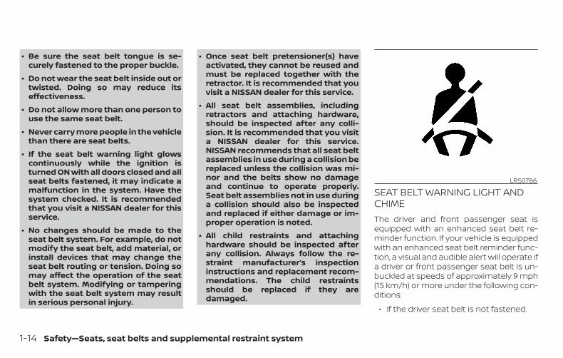
SEAT BELT WARNING LIGHT ANDCHIMEThe driver and front passenger seat isequipped with an enhanced seat belt re-minder function. If your vehicle is equippedwith an enhanced seat belt reminder func-tion, a visual and audible alert will operate ifa driver or front passenger seat belt is un-buckled at speeds of approximately 9 mph(15 km/h) or more under the following con-ditions:
∙ If the driver seat belt is not fastened.
LRS0786
1-14 Safety—Seats, seat belts and supplemental restraint system
∙ The front passenger’s seat belt is notfastened and the seat is occupied by apassenger for 7 seconds after the igni-tion switch is placed in the ON position.
∙ The front passenger’s seat belt is notfastened and objects or external forceon the passenger seat change the seatbelt reminder classification to Occu-pied.
The seat belt warning light will flash underthe conditions shown above until the nec-essary seat belt is securely fastened.
A warning chime will sound for approxi-mately 90 seconds or until one of the fol-lowing conditions is met:
∙ The unbuckled front occupant’s seatbelt is securely fastened.
∙ The seat belt reminder function in thefront passenger seat no longer detectsthat the front passenger seat is occu-pied.
∙ The ignition is turned off.
The below situations could result in theseat belt reminder light being illuminatedand the chime sounding, even with no oc-cupant present in the passenger seat:
∙ Heavy objects placed on the seat.
∙ Someone pushing or pulling on thefront passenger seat.
∙ An object placed under the front pas-senger seat.
∙ An object placed between the seatcushion and center console or betweenthe seat cushion and the door.
∙ An object hanging on the seat or placedin the seatback pocket.
∙ A child restraint or other object pressingagainst the rear of the seatback.
PREGNANT WOMENNISSAN recommends that pregnantwomen use seat belts. The seat belt shouldbe worn snug and always position the lapbelt as low as possible around the hips, notthe waist. Place the shoulder belt over yourshoulder and across your chest. Never runthe lap/shoulder belt over your abdominalarea. Contact your doctor for specific rec-ommendations.
INJURED PERSONSNISSAN recommends that injured personsuse seat belts. Check with your doctor forspecific recommendations.
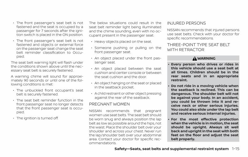
THREE-POINT TYPE SEAT BELTWITH RETRACTOR
WARNING∙ Every person who drives or rides in
this vehicle should use a seat belt atall times. Children should be in therear seats and in an appropriaterestraint.
∙ Do not ride in a moving vehicle whenthe seatback is reclined. This can bedangerous. The shoulder belt will notbe against your body. In an accident,you could be thrown into it and re-ceive neck or other serious injuries.You could also slide under the lap beltand receive serious internal injuries.
∙ For the most effective protectionwhen the vehicle is in motion, the seatshould be upright. Always sit wellback and upright in the seat with bothfeet on the floor and adjust the seatbelt properly.
Safety—Seats, seat belts and supplemental restraint system 1-15
∙ Do not allow children to play with theseat belts. Most seating positions areequipped with Automatic Locking Re-tractor (ALR) mode seat belts. If theseat belt becomes wrapped around achild’s neck with the ALR mode acti-vated, the child can be seriously in-jured or killed if the seat belt retractsand becomes tight. This can occureven if the vehicle is parked. Unbucklethe seat belt to release the child. If theseat belt cannot be unbuckled or isalready unbuckled, release the childby cutting the seat belt with a suitabletool (such as a knife or scissors) torelease the seat belt.
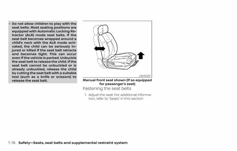
Fastening the seat belts1. Adjust the seat. For additional informa-
tion, refer to “Seats” in this section.
Manual front seat shown (if so equippedfor passenger’s seat)
LRS3029
1-16 Safety—Seats, seat belts and supplemental restraint system
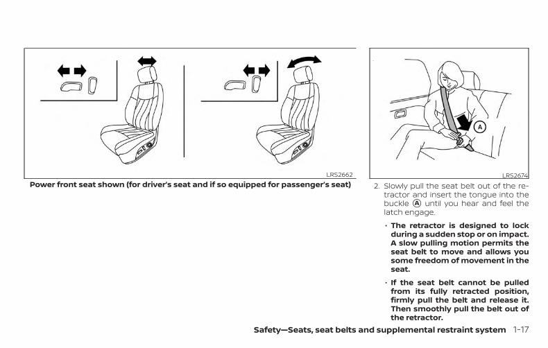
2. Slowly pull the seat belt out of the re-tractor and insert the tongue into thebuckle �A until you hear and feel thelatch engage.
∙ The retractor is designed to lockduring a sudden stop or on impact.A slow pulling motion permits theseat belt to move and allows yousome freedom of movement in theseat.
∙ If the seat belt cannot be pulledfrom its fully retracted position,firmly pull the belt and release it.Then smoothly pull the belt out ofthe retractor.
Power front seat shown (for driver’s seat and if so equipped for passenger’s seat)LRS2662 LRS2674
Safety—Seats, seat belts and supplemental restraint system 1-17
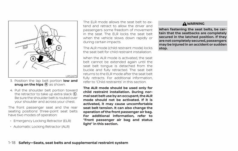
3. Position the lap belt portion low andsnug on the hips �B as shown.
4. Pull the shoulder belt portion towardthe retractor to take up extra slack �C .Be sure the shoulder belt is routed overyour shoulder and across your chest.
The front passenger seat and the rearseating positions’ three-point seat beltshave two modes of operation:
∙ Emergency Locking Retractor (ELR)
∙ Automatic Locking Retractor (ALR)
The ELR mode allows the seat belt to ex-tend and retract to allow the driver andpassengers some freedom of movementin the seat. The ELR locks the seat beltwhen the vehicle slows down rapidly orduring certain impacts.
The ALR mode (child restraint mode) locksthe seat belt for child restraint installation.
When the ALR mode is activated, the seatbelt cannot be extended again until theseat belt tongue is detached from thebuckle and fully retracted. The seat beltreturns to the ELR mode after the seat beltfully retracts. For additional information,refer to “Child restraints” in this section.
The ALR mode should be used only forchild restraint installation. During nor-mal seat belt use by an occupant, the ALRmode should not be activated. If it isactivated, it may cause uncomfortableseat belt tension. It can also change theoperation of the front passenger air bag.For additional information, refer to“Front passenger air bag and statuslight” in this section.
WARNINGWhen fastening the seat belts, be cer-tain that the seatbacks are completelysecured in the latched position. If theyare not completely secured, passengersmay be injured in an accident or suddenstop.
LRS2675
1-18 Safety—Seats, seat belts and supplemental restraint system
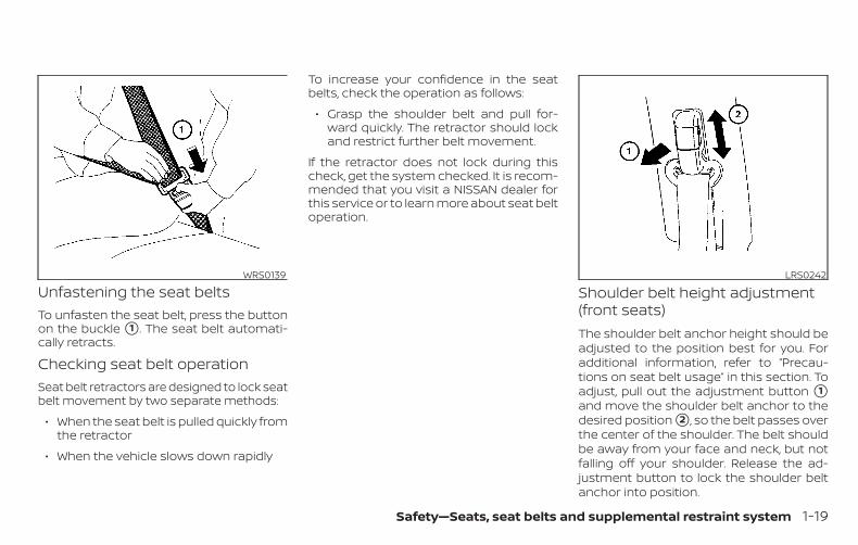
Unfastening the seat beltsTo unfasten the seat belt, press the buttonon the buckle �1 . The seat belt automati-cally retracts.
Checking seat belt operationSeat belt retractors are designed to lock seatbelt movement by two separate methods:
∙ When the seat belt is pulled quickly fromthe retractor
∙ When the vehicle slows down rapidly
To increase your confidence in the seatbelts, check the operation as follows:
∙ Grasp the shoulder belt and pull for-ward quickly. The retractor should lockand restrict further belt movement.
If the retractor does not lock during thischeck, get the system checked. It is recom-mended that you visit a NISSAN dealer forthis service or to learn more about seat beltoperation.
Shoulder belt height adjustment(front seats)The shoulder belt anchor height should beadjusted to the position best for you. Foradditional information, refer to “Precau-tions on seat belt usage” in this section. Toadjust, pull out the adjustment button �1and move the shoulder belt anchor to thedesired position �2 , so the belt passes overthe center of the shoulder. The belt shouldbe away from your face and neck, but notfalling off your shoulder. Release the ad-justment button to lock the shoulder beltanchor into position.
WRS0139 LRS0242
Safety—Seats, seat belts and supplemental restraint system 1-19
WARNING∙ After adjustment, release the adjust-
ment button and try to move theshoulder belt anchor up and down tomake sure it is securely fixed inposition.
∙ The shoulder belt anchor heightshould be adjusted to the positionbest for you. Failure to do so may re-duce the effectiveness of the entirerestraint system and increase thechance or severity of injury in anaccident.
SEAT BELT EXTENDERSIf, because of body size or driving position, itis not possible to properly fit thelap/shoulder belt and fasten it, an extenderthat is compatible with the installed seatbelts is available for purchase. The ex-tender adds approximately 8 in (200 mm)of length and may be used for either thedriver or front passenger seating position.It is recommended that you visit a NISSANdealer for assistance with purchasing anextender if an extender is required.
WARNING∙ Only NISSAN seat belt extenders,
made by the same company whichmade the original equipment seatbelts, should be used with NISSANseat belts.
∙ Adults and children who can use thestandard seat belt should not use anextender. Such unnecessary usecould result in serious personal injuryin the event of an accident.
∙ Never use seat belt extenders to in-stall child restraints. If the child re-straint is not secured properly, thechild could be seriously injured orkilled in a collision or a sudden stop.
SEAT BELT MAINTENANCE∙ To clean the seat belt webbing, apply
a mild soap solution or any solution rec-ommended for cleaning upholstery orcarpet. Then wipe with a cloth and allowthe seat belts to dry in the shade. Do notallow the seat belts to retract until theyare completely dry.
∙ If dirt builds up in the shoulder beltguide of the seat belt anchors, theseat belts may retract slowly. Wipe theshoulder belt guide with a clean, drycloth.
∙ Periodically check to see that the seatbelt and the metal components, suchas buckles, tongues, retractors, flexiblewires and anchors, work properly. Ifloose parts, deterioration, cuts or otherdamage on the webbing is found, theentire seat belt assembly should be re-placed.
1-20 Safety—Seats, seat belts and supplemental restraint system
WARNINGDo not allow children to play with theseat belts. Most seating positions areequipped with Automatic Locking Re-tractor (ALR) mode seat belts. If the seatbelt becomes wrapped around a child’sneck with the ALR mode activated, thechild can be seriously injured or killed ifthe seat belt retracts and becomestight. This can occur even if the vehicleis parked. Unbuckle the seat belt to re-lease the child. If the seat belt cannot beunbuckled or is already unbuckled, re-lease the child by cutting the seat beltwith a suitable tool (such as a knife orscissors) to release the seat belt.
Children need adults to help protect them.They need to be properly restrained.
In addition to the general information inthis manual, child safety information isavailable from many other sources, includ-ing doctors, teachers, government trafficsafety offices, and community organiza-tions. Every child is different, so be sure tolearn the best way to transport your child.
There are three basic types of child re-straint systems:
∙ Rear-facing child restraints
∙ Forward-facing child restraints
∙ Booster seats
The proper restraint depends on the child’ssize. Generally, infants up to about 1 yearand less than 20 lbs. (9 kg) should be placedin rear-facing child restraints. Forward-facing child restraints are available for chil-dren who outgrow rear-facing child re-straints and are at least 1 year old. Boosterseats are used to help position a vehiclelap/shoulder belt on a child who can nolonger use a forward-facing child restraint.
WARNINGInfants and children need special pro-tection. The vehicle’s seat belts may notfit them properly. The shoulder belt maycome too close to the face or neck.The lap belt may not fit over their smallhip bones. In an accident, an improperlyfitting seat belt could cause serious orfatal injury. Always use appropriatechild restraints.
All U.S. states and Canadian provinces orterritories require the use of approved childrestraints for infants and small children.For additional information, refer to “Childrestraints” in this section.
A child restraint may be secured in the ve-hicle by using either the LATCH (LowerAnchors and Tethers for CHildren) systemor with the vehicle seat belt. For additionalinformation, refer to “Child restraints” in thissection.
NISSAN recommends that all pre-teensand children be restrained in the rearseat. Studies show that children aresafer when properly restrained in therear seat than in the front seat.
This is especially important becauseyour vehicle has a supplemental re-straint system (air bag system) for thefront passenger. For additional informa-tion, refer to “Supplemental RestraintSystem (SRS)” in this section.
CHILD SAFETY
Safety—Seats, seat belts and supplemental restraint system 1-21
INFANTSInfants up to at least 1 year old should beplaced in a rear-facing child restraint. NISSANrecommends that infants be placed in childrestraints that comply with Federal MotorVehicle Safety Standards or Canadian MotorVehicle Safety Standards. You should choosea child restraint that fits your vehicle andalways follow the manufacturer’s instruc-tions for installation and use.
SMALL CHILDRENChildren that are over 1 year old and weighat least 20 lbs. (9 kg) should remain in arear-facing child restraint as long as pos-sible up to the height or weight limit of thechild restraint. Children who outgrow theheight or weight limit of the rear-facingchild restraint and are at least 1 year oldshould be secured in a forward-facing childrestraint with a harness. Refer to the manu-facturer’s instructions for minimum andmaximum weight and height recommen-dations. NISSAN recommends that smallchildren be placed in child restraints thatcomply with Federal Motor Vehicle SafetyStandards or Canadian Motor VehicleSafety Standards. You should choose a
child restraint that fits your vehicle andalways follow the manufacturer’s instruc-tions for installation and use.
LARGER CHILDRENChildren should remain in a forward-facingchild restraint with a harness until they reachthe maximum height or weight limit allowedby the child restraint manufacturer.
Once a child outgrows the height or weightlimit of the harness-equipped forward-facing child restraint, NISSAN recommendsthat the child be placed in a commerciallyavailable booster seat to obtain properseat belt fit. For a seat belt to fit properly, thebooster seat should raise the child so thatthe shoulder belt is properly positionedacross the chest and the top, middle por-tion of the shoulder. The shoulder beltshould not cross the neck or face andshould not fall off the shoulder. The lap beltshould lie snugly across the lower hips orupper thighs, not the abdomen. A boosterseat can only be used in seating positionsthat have a three-point type seat belt. Thebooster seat should fit the vehicle seat andhave a label certifying that it complies withFederal Motor Vehicle Safety Standards orCanadian Motor Vehicle Safety Standards.
A booster seat should be used until thechild can pass the seat belt fit test below:
∙ Are the child’s back and hips against thevehicle seatback?
∙ Is the child able to sit without slouch-ing?
∙ Do the child’s knees bend easily overthe front edge of the seat with feet flaton the floor?
∙ Can the child safely wear the seat belt(lap belt low and snug across the hipsand shoulder belt across mid-chestand shoulder)?
∙ Is the child able to use the properly ad-justed head restraint/headrest?
∙ Will the child be able to stay in positionfor the entire ride?
1-22 Safety—Seats, seat belts and supplemental restraint system
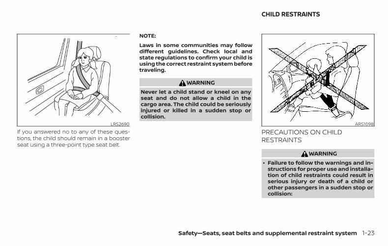
If you answered no to any of these ques-tions, the child should remain in a boosterseat using a three-point type seat belt.
NOTE:
Laws in some communities may followdifferent guidelines. Check local andstate regulations to confirm your child isusing the correct restraint system beforetraveling.
WARNINGNever let a child stand or kneel on anyseat and do not allow a child in thecargo area. The child could be seriouslyinjured or killed in a sudden stop orcollision.
PRECAUTIONS ON CHILDRESTRAINTS
WARNING∙ Failure to follow the warnings and in-
structions for proper use and installa-tion of child restraints could result inserious injury or death of a child orother passengers in a sudden stop orcollision:
LRS2690 ARS1098
CHILD RESTRAINTS
Safety—Seats, seat belts and supplemental restraint system 1-23
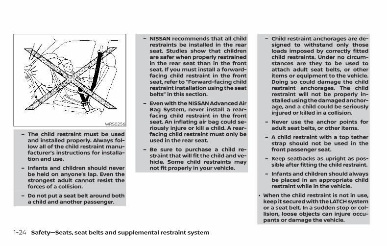
– The child restraint must be usedand installed properly. Always fol-low all of the child restraint manu-facturer’s instructions for installa-tion and use.
– Infants and children should neverbe held on anyone’s lap. Even thestrongest adult cannot resist theforces of a collision.
– Do not put a seat belt around botha child and another passenger.
– NISSAN recommends that all childrestraints be installed in the rearseat. Studies show that childrenare safer when properly restrainedin the rear seat than in the frontseat. If you must install a forward-facing child restraint in the frontseat, refer to “Forward-facing childrestraint installation using the seatbelts” in this section.
– Even with the NISSAN Advanced AirBag System, never install a rear-facing child restraint in the frontseat. An inflating air bag could se-riously injure or kill a child. A rear-facing child restraint must only beused in the rear seat.
– Be sure to purchase a child re-straint that will fit the child and ve-hicle. Some child restraints maynot fit properly in your vehicle.
– Child restraint anchorages are de-signed to withstand only thoseloads imposed by correctly fittedchild restraints. Under no circum-stances are they to be used toattach adult seat belts, or otheritems or equipment to the vehicle.Doing so could damage the childrestraint anchorages. The childrestraint will not be properly in-stalled using the damaged anchor-age, and a child could be seriouslyinjured or killed in a collision.
– Never use the anchor points foradult seat belts, or other items.
– A child restraint with a top tetherstrap should not be used in thefront passenger seat.
– Keep seatbacks as upright as pos-sible after fitting the child restraint.
– Infants and children should alwaysbe placed in an appropriate childrestraint while in the vehicle.
∙ When the child restraint is not in use,keep it secured with the LATCH systemor a seat belt. In a sudden stop or col-lision, loose objects can injure occu-pants or damage the vehicle.
WRS0256
1-24 Safety—Seats, seat belts and supplemental restraint system
CAUTIONA child restraint in a closed vehicle canbecome very hot. Check the seatingsurface and buckles before placing achild in the child restraint.
This vehicle is equipped with a universalchild restraint anchor system, referred toas the LATCH (Lower Anchors and Tethersfor CHildren) system. Some child restraintsinclude rigid or webbing-mounted attach-ments that can be connected to these an-chors. For additional information, refer to“LATCH (Lower Anchors and Tethers forCHildren) system” in this section.
If you do not have a LATCH compatiblechild restraint, the vehicle seat belts can beused.
Several manufacturers offer child re-straints for infants and children of varioussizes. When selecting any child restraint,keep the following points in mind:
∙ Choose only a restraint with a label cer-tifying that it complies with Federal Mo-tor Vehicle Safety Standard 213 or Cana-dian Motor Vehicle Safety Standard 213.
∙ Check the child restraint in your vehicleto be sure it is compatible with the vehi-cle’s seat and seat belt system.
∙ If the child restraint is compatible withyour vehicle, place your child in the childrestraint and check the various adjust-ments to be sure the child restraint iscompatible with your child. Choose achild restraint that is designed for yourchild’s height and weight. Always followall recommended procedures.
∙ If the combined weight of the child andchild restraint is less than 65 lbs. (29.5 kg),you may use either the LATCH anchors orthe seat belt to install the child restraint(not both at the same time).
∙ If the combined weight of the child andchild restraint is greater than 65 lbs.(29.5 kg), use the vehicle’s seat belt (notthe lower anchors) to install the childrestraint.
∙ Be sure to follow the child restraintmanufacturer’s instructions for installa-tion.
All U.S. states and Canadian provinces orterritories require that infants and smallchildren be restrained in an approvedchild restraint at all times while the ve-hicle is being operated. Canadian law re-quires the top tether strap on forward-facing child restraints be secured to thedesignated anchor point on the vehicle.
Safety—Seats, seat belts and supplemental restraint system 1-25
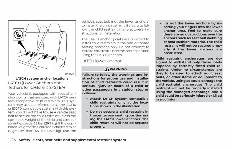
LATCH (Lower Anchors andTethers for CHildren) SYSTEMYour vehicle is equipped with special an-chor points that are used with LATCH sys-tem compatible child restraints. This sys-tem may also be referred to as the ISOFIXor ISOFIX compatible system. With this sys-tem, you do not have to use a vehicle seatbelt to secure the child restraint unless thecombined weight of the child and child re-straint exceeds 65 lbs. (29.5 kg). If the com-bined weight of the child and child restraintis greater than 65 lbs. (29.5 kg), use the
vehicle’s seat belt (not the lower anchors)to install the child restraint. Be sure to fol-low the child restraint manufacturer’s in-structions for installation.
The LATCH anchor points are provided toinstall child restraints in the rear outboardseating positions only. Do not attempt toinstall a child restraint in the center positionusing the LATCH anchors.
LATCH lower anchor
WARNINGFailure to follow the warnings and in-structions for proper use and installa-tion of child restraints could result inserious injury or death of a child orother passengers in a sudden stop orcollision:
– Attach LATCH system compatiblechild restraints only at the loca-tions shown in the illustration.
– Do not secure a child restraint inthe center rear seating position us-ing the LATCH lower anchors. Thechild restraint will not be securedproperly.
– Inspect the lower anchors by in-serting your fingers into the loweranchor area. Feel to make surethere are no obstructions over theanchors such as seat belt webbingor seat cushion material. The childrestraint will not be secured prop-erly if the lower anchors areobstructed.
Child restraint anchorages are de-signed to withstand only those loadsimposed by correctly fitted child re-straints. Under no circumstances arethey to be used to attach adult seatbelts, or other items or equipment tothe vehicle. Doing so could damage thechild restraint anchorages. The childrestraint will not be properly installedusing the damaged anchorage, and achild could be seriously injured or killedin a collision.
LATCH system anchor locationsLRS2165
1-26 Safety—Seats, seat belts and supplemental restraint system
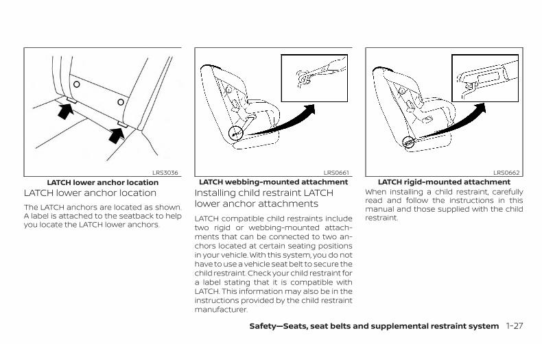
LATCH lower anchor locationThe LATCH anchors are located as shown.A label is attached to the seatback to helpyou locate the LATCH lower anchors.
Installing child restraint LATCHlower anchor attachmentsLATCH compatible child restraints includetwo rigid or webbing-mounted attach-ments that can be connected to two an-chors located at certain seating positionsin your vehicle. With this system, you do nothave to use a vehicle seat belt to secure thechild restraint. Check your child restraint fora label stating that it is compatible withLATCH. This information may also be in theinstructions provided by the child restraintmanufacturer.
When installing a child restraint, carefullyread and follow the instructions in thismanual and those supplied with the childrestraint.
LATCH lower anchor locationLRS3036
LATCH webbing-mounted attachmentLRS0661
LATCH rigid-mounted attachmentLRS0662
Safety—Seats, seat belts and supplemental restraint system 1-27
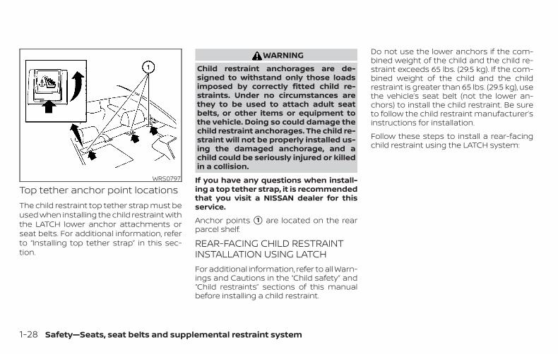
Top tether anchor point locationsThe child restraint top tether strap must beused when installing the child restraint withthe LATCH lower anchor attachments orseat belts. For additional information, referto “Installing top tether strap” in this sec-tion.
WARNINGChild restraint anchorages are de-signed to withstand only those loadsimposed by correctly fitted child re-straints. Under no circumstances arethey to be used to attach adult seatbelts, or other items or equipment tothe vehicle. Doing so could damage thechild restraint anchorages. The child re-straint will not be properly installed us-ing the damaged anchorage, and achild could be seriously injured or killedin a collision.
If you have any questions when install-ing a top tether strap, it is recommendedthat you visit a NISSAN dealer for thisservice.
Anchor points �1 are located on the rearparcel shelf.
REAR-FACING CHILD RESTRAINTINSTALLATION USING LATCHFor additional information, refer to all Warn-ings and Cautions in the “Child safety” and“Child restraints” sections of this manualbefore installing a child restraint.
Do not use the lower anchors if the com-bined weight of the child and the child re-straint exceeds 65 lbs. (29.5 kg). If the com-bined weight of the child and the childrestraint is greater than 65 lbs. (29.5 kg), usethe vehicle’s seat belt (not the lower an-chors) to install the child restraint. Be sureto follow the child restraint manufacturer’sinstructions for installation.
Follow these steps to install a rear-facingchild restraint using the LATCH system:
WRS0797
1-28 Safety—Seats, seat belts and supplemental restraint system
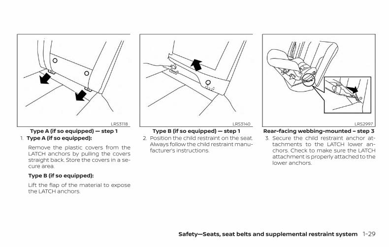
1. Type A (if so equipped):
Remove the plastic covers from theLATCH anchors by pulling the coversstraight back. Store the covers in a se-cure area.
Type B (if so equipped):
Lift the flap of the material to exposethe LATCH anchors.
2. Position the child restraint on the seat.Always follow the child restraint manu-facturer’s instructions.
3. Secure the child restraint anchor at-tachments to the LATCH lower an-chors. Check to make sure the LATCHattachment is properly attached to thelower anchors.
Type A (if so equipped) — step 1LRS3118
Type B (if so equipped) — step 1LRS3140
Rear-facing webbing-mounted – step 3LRS2997
Safety—Seats, seat belts and supplemental restraint system 1-29
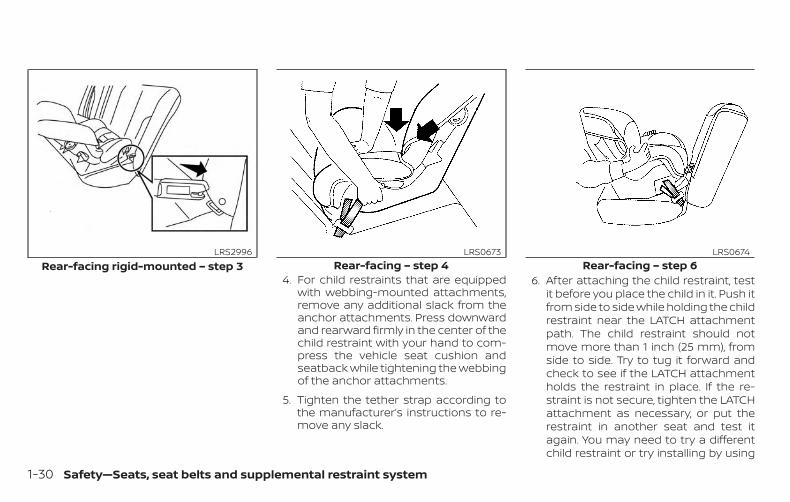
4. For child restraints that are equippedwith webbing-mounted attachments,remove any additional slack from theanchor attachments. Press downwardand rearward firmly in the center of thechild restraint with your hand to com-press the vehicle seat cushion andseatback while tightening the webbingof the anchor attachments.
5. Tighten the tether strap according tothe manufacturer’s instructions to re-move any slack.
6. After attaching the child restraint, testit before you place the child in it. Push itfrom side to side while holding the childrestraint near the LATCH attachmentpath. The child restraint should notmove more than 1 inch (25 mm), fromside to side. Try to tug it forward andcheck to see if the LATCH attachmentholds the restraint in place. If the re-straint is not secure, tighten the LATCHattachment as necessary, or put therestraint in another seat and test itagain. You may need to try a differentchild restraint or try installing by using
Rear-facing rigid-mounted – step 3LRS2996
Rear-facing – step 4LRS0673
Rear-facing – step 6LRS0674
1-30 Safety—Seats, seat belts and supplemental restraint system
the vehicle seat belt (if applicable). Notall child restraints fit in all types of ve-hicles.
7. Check to make sure the child restraintis properly secured prior to each use. Ifthe child restraint is loose, repeatsteps 2 through 6.
8. Type A (if so equipped):
If you remove the child restraint, rein-stall the plastic LATCH anchor coversafter use by pushing the coversstraight onto the LATCH anchors.
Type B (if so equipped):
If you remove the child restraint, se-curely replace the flap by pressing thematerial firmly against the seat.
REAR-FACING CHILD RESTRAINTINSTALLATION USING THE SEATBELTS
WARNINGThe three-point seat belt with Auto-matic Locking Retractor (ALR) must beused when installing a child restraint.Failure to use the ALR mode will result inthe child restraint not being properlysecured. The restraint could tip over orbe loose and cause injury to a child in asudden stop or collision.
For additional information, refer to all Warn-ings and Cautions in the “Child safety” and“Child restraints” sections of this manualbefore installing a child restraint.
Do not use the lower anchors if the com-bined weight of the child and the child re-straint exceeds 65 lbs. (29.5 kg). If the com-bined weight of the child and the childrestraint is greater than 65 lbs. (29.5 kg),use the vehicle’s seat belt (not the loweranchors) to install the child restraint. Besure to follow the child restraint manufac-turer’s instructions for installation.
Follow these steps to install a rear-facingchild restraint using the vehicle seat belts inthe rear seats:
Safety—Seats, seat belts and supplemental restraint system 1-31
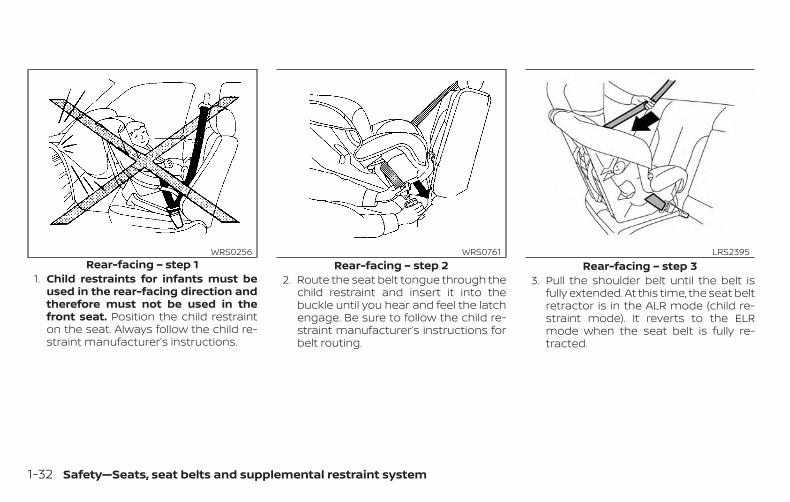
1. Child restraints for infants must beused in the rear-facing direction andtherefore must not be used in thefront seat. Position the child restrainton the seat. Always follow the child re-straint manufacturer’s instructions.
2. Route the seat belt tongue through thechild restraint and insert it into thebuckle until you hear and feel the latchengage. Be sure to follow the child re-straint manufacturer’s instructions forbelt routing.
3. Pull the shoulder belt until the belt isfully extended. At this time, the seat beltretractor is in the ALR mode (child re-straint mode). It reverts to the ELRmode when the seat belt is fully re-tracted.
Rear-facing – step 1WRS0256
Rear-facing – step 2WRS0761
Rear-facing – step 3LRS2395
1-32 Safety—Seats, seat belts and supplemental restraint system
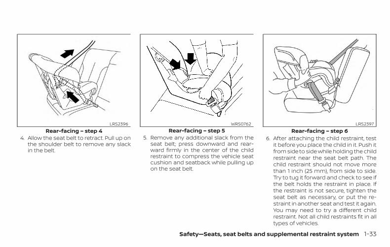
4. Allow the seat belt to retract. Pull up onthe shoulder belt to remove any slackin the belt.
5. Remove any additional slack from theseat belt; press downward and rear-ward firmly in the center of the childrestraint to compress the vehicle seatcushion and seatback while pulling upon the seat belt.
6. After attaching the child restraint, testit before you place the child in it. Push itfrom side to side while holding the childrestraint near the seat belt path. Thechild restraint should not move morethan 1 inch (25 mm), from side to side.Try to tug it forward and check to see ifthe belt holds the restraint in place. Ifthe restraint is not secure, tighten theseat belt as necessary, or put the re-straint in another seat and test it again.You may need to try a different childrestraint. Not all child restraints fit in alltypes of vehicles.
Rear-facing – step 4LRS2396
Rear-facing – step 5WRS0762
Rear-facing – step 6LRS2397
Safety—Seats, seat belts and supplemental restraint system 1-33
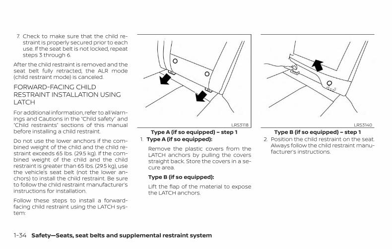
7. Check to make sure that the child re-straint is properly secured prior to eachuse. If the seat belt is not locked, repeatsteps 3 through 6.
After the child restraint is removed and theseat belt fully retracted, the ALR mode(child restraint mode) is canceled.
FORWARD-FACING CHILDRESTRAINT INSTALLATION USINGLATCHFor additional information, refer to all Warn-ings and Cautions in the “Child safety” and“Child restraints” sections of this manualbefore installing a child restraint.
Do not use the lower anchors if the com-bined weight of the child and the child re-straint exceeds 65 lbs. (29.5 kg). If the com-bined weight of the child and the childrestraint is greater than 65 lbs. (29.5 kg), usethe vehicle’s seat belt (not the lower an-chors) to install the child restraint. Be sureto follow the child restraint manufacturer’sinstructions for installation.
Follow these steps to install a forward-facing child restraint using the LATCH sys-tem:
1. Type A (if so equipped):
Remove the plastic covers from theLATCH anchors by pulling the coversstraight back. Store the covers in a se-cure area.
Type B (if so equipped):
Lift the flap of the material to exposethe LATCH anchors.
2. Position the child restraint on the seat.Always follow the child restraint manu-facturer’s instructions.
Type A (if so equipped) – step 1LRS3118
Type B (if so equipped) – step 1LRS3140
1-34 Safety—Seats, seat belts and supplemental restraint system
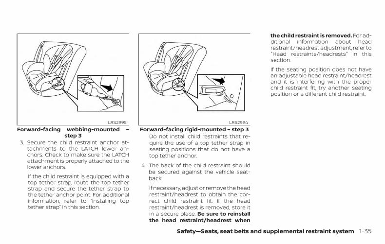
3. Secure the child restraint anchor at-tachments to the LATCH lower an-chors. Check to make sure the LATCHattachment is properly attached to thelower anchors.
If the child restraint is equipped with atop tether strap, route the top tetherstrap and secure the tether strap tothe tether anchor point. For additionalinformation, refer to “Installing toptether strap” in this section.
Do not install child restraints that re-quire the use of a top tether strap inseating positions that do not have atop tether anchor.
4. The back of the child restraint shouldbe secured against the vehicle seat-back.
If necessary, adjust or remove the headrestraint/headrest to obtain the cor-rect child restraint fit. If the headrestraint/headrest is removed, store itin a secure place. Be sure to reinstallthe head restraint/headrest when
the child restraint is removed. For ad-ditional information about headrestraint/headrest adjustment, refer to"Head restraints/headrests" in thissection.
If the seating position does not havean adjustable head restraint/headrestand it is interfering with the properchild restraint fit, try another seatingposition or a different child restraint.
Forward-facing webbing-mounted –step 3
LRS2995Forward-facing rigid-mounted – step 3
LRS2994
Safety—Seats, seat belts and supplemental restraint system 1-35
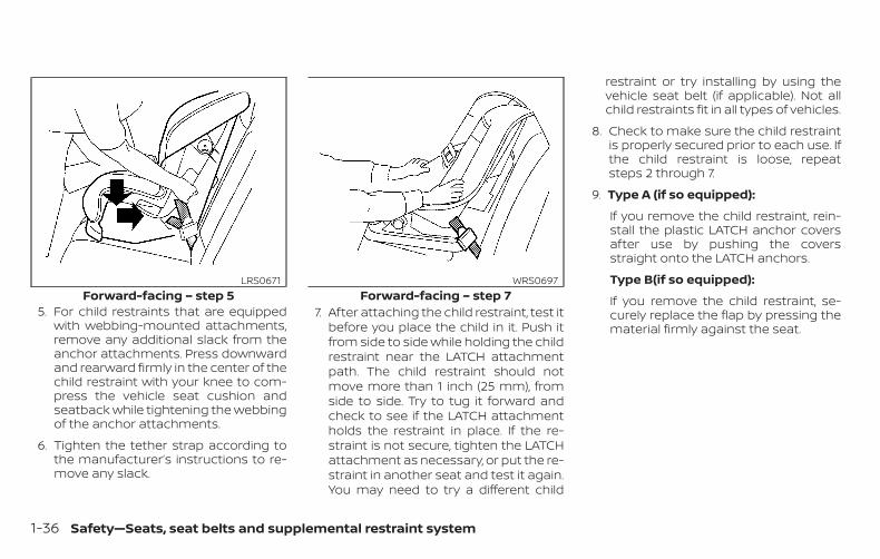
5. For child restraints that are equippedwith webbing-mounted attachments,remove any additional slack from theanchor attachments. Press downwardand rearward firmly in the center of thechild restraint with your knee to com-press the vehicle seat cushion andseatback while tightening the webbingof the anchor attachments.
6. Tighten the tether strap according tothe manufacturer’s instructions to re-move any slack.
7. After attaching the child restraint, test itbefore you place the child in it. Push itfrom side to side while holding the childrestraint near the LATCH attachmentpath. The child restraint should notmove more than 1 inch (25 mm), fromside to side. Try to tug it forward andcheck to see if the LATCH attachmentholds the restraint in place. If the re-straint is not secure, tighten the LATCHattachment as necessary, or put the re-straint in another seat and test it again.You may need to try a different child
restraint or try installing by using thevehicle seat belt (if applicable). Not allchild restraints fit in all types of vehicles.
8. Check to make sure the child restraintis properly secured prior to each use. Ifthe child restraint is loose, repeatsteps 2 through 7.
9. Type A (if so equipped):
If you remove the child restraint, rein-stall the plastic LATCH anchor coversafter use by pushing the coversstraight onto the LATCH anchors.
Type B(if so equipped):
If you remove the child restraint, se-curely replace the flap by pressing thematerial firmly against the seat.
Forward-facing – step 5LRS0671
Forward-facing – step 7WRS0697
1-36 Safety—Seats, seat belts and supplemental restraint system
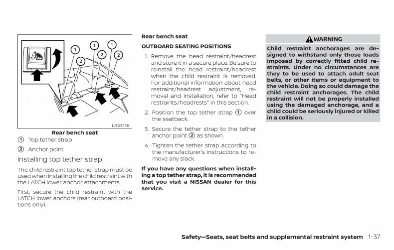
�1 Top tether strap
�2 Anchor point
Installing top tether strapThe child restraint top tether strap must beused when installing the child restraint withthe LATCH lower anchor attachments.
First, secure the child restraint with theLATCH lower anchors (rear outboard posi-tions only).
Rear bench seat
OUTBOARD SEATING POSITIONS
1. Remove the head restraint/headrestand store it in a secure place. Be sure toreinstall the head restraint/headrestwhen the child restraint is removed.For additional information about headrestraint/headrest adjustment, re-moval and installation, refer to "Headrestraints/headrests" in this section.
2. Position the top tether strap �1 overthe seatback.
3. Secure the tether strap to the tetheranchor point �2 as shown.
4. Tighten the tether strap according tothe manufacturer’s instructions to re-move any slack.
If you have any questions when install-ing a top tether strap, it is recommendedthat you visit a NISSAN dealer for thisservice.
WARNINGChild restraint anchorages are de-signed to withstand only those loadsimposed by correctly fitted child re-straints. Under no circumstances arethey to be used to attach adult seatbelts, or other items or equipment tothe vehicle. Doing so could damage thechild restraint anchorages. The childrestraint will not be properly installedusing the damaged anchorage, and achild could be seriously injured or killedin a collision.
Rear bench seatLRS3176
Safety—Seats, seat belts and supplemental restraint system 1-37
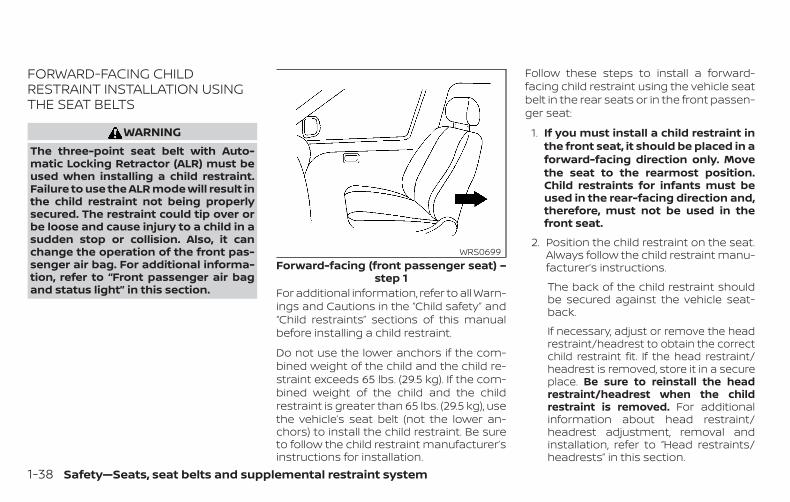
FORWARD-FACING CHILDRESTRAINT INSTALLATION USINGTHE SEAT BELTS
WARNINGThe three-point seat belt with Auto-matic Locking Retractor (ALR) must beused when installing a child restraint.Failure to use the ALR mode will result inthe child restraint not being properlysecured. The restraint could tip over orbe loose and cause injury to a child in asudden stop or collision. Also, it canchange the operation of the front pas-senger air bag. For additional informa-tion, refer to “Front passenger air bagand status light” in this section. For additional information, refer to all Warn-
ings and Cautions in the “Child safety” and“Child restraints” sections of this manualbefore installing a child restraint.
Do not use the lower anchors if the com-bined weight of the child and the child re-straint exceeds 65 lbs. (29.5 kg). If the com-bined weight of the child and the childrestraint is greater than 65 lbs. (29.5 kg), usethe vehicle’s seat belt (not the lower an-chors) to install the child restraint. Be sureto follow the child restraint manufacturer’sinstructions for installation.
Follow these steps to install a forward-facing child restraint using the vehicle seatbelt in the rear seats or in the front passen-ger seat:
1. If you must install a child restraint inthe front seat, it should be placed in aforward-facing direction only. Movethe seat to the rearmost position.Child restraints for infants must beused in the rear-facing direction and,therefore, must not be used in thefront seat.
2. Position the child restraint on the seat.Always follow the child restraint manu-facturer’s instructions.
The back of the child restraint shouldbe secured against the vehicle seat-back.
If necessary, adjust or remove the headrestraint/headrest to obtain the correctchild restraint fit. If the head restraint/headrest is removed, store it in a secureplace. Be sure to reinstall the headrestraint/headrest when the childrestraint is removed. For additionalinformation about head restraint/headrest adjustment, removal andinstallation, refer to “Head restraints/headrests” in this section.
Forward-facing (front passenger seat) –step 1
WRS0699
1-38 Safety—Seats, seat belts and supplemental restraint system
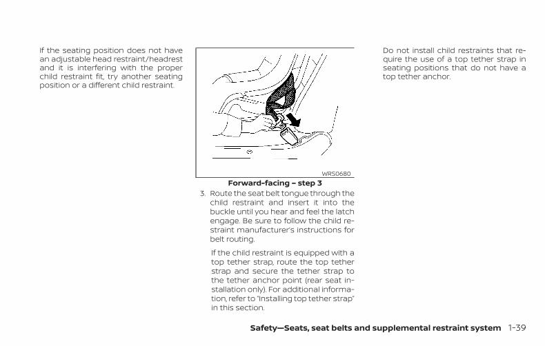
If the seating position does not havean adjustable head restraint/headrestand it is interfering with the properchild restraint fit, try another seatingposition or a different child restraint.
3. Route the seat belt tongue through thechild restraint and insert it into thebuckle until you hear and feel the latchengage. Be sure to follow the child re-straint manufacturer’s instructions forbelt routing.
If the child restraint is equipped with atop tether strap, route the top tetherstrap and secure the tether strap tothe tether anchor point (rear seat in-stallation only). For additional informa-tion, refer to “Installing top tether strap”in this section.
Do not install child restraints that re-quire the use of a top tether strap inseating positions that do not have atop tether anchor.
Forward-facing – step 3WRS0680
Safety—Seats, seat belts and supplemental restraint system 1-39
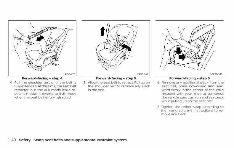
4. Pull the shoulder belt until the belt isfully extended. At this time, the seat beltretractor is in the ALR mode (child re-straint mode). It reverts to ELR modewhen the seat belt is fully retracted.
5. Allow the seat belt to retract. Pull up onthe shoulder belt to remove any slackin the belt.
6. Remove any additional slack from theseat belt; press downward and rear-ward firmly in the center of the childrestraint with your knee to compressthe vehicle seat cushion and seatbackwhile pulling up on the seat belt.
7. Tighten the tether strap according tothe manufacturer’s instructions to re-move any slack.
Forward-facing – step 4LRS0667
Forward-facing – step 5LRS0668
Forward-facing – step 6WRS0681
1-40 Safety—Seats, seat belts and supplemental restraint system
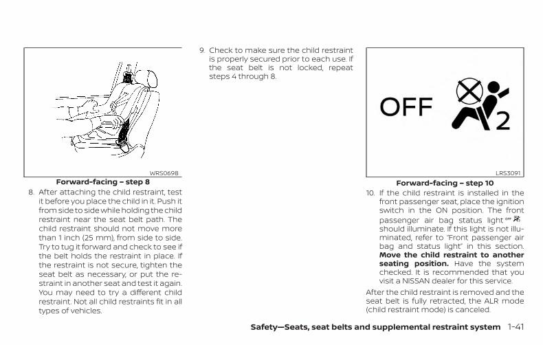
8. After attaching the child restraint, testit before you place the child in it. Push itfrom side to side while holding the childrestraint near the seat belt path. Thechild restraint should not move morethan 1 inch (25 mm), from side to side.Try to tug it forward and check to see ifthe belt holds the restraint in place. Ifthe restraint is not secure, tighten theseat belt as necessary, or put the re-straint in another seat and test it again.You may need to try a different childrestraint. Not all child restraints fit in alltypes of vehicles.
9. Check to make sure the child restraintis properly secured prior to each use. Ifthe seat belt is not locked, repeatsteps 4 through 8.
10. If the child restraint is installed in thefront passenger seat, place the ignitionswitch in the ON position. The frontpassenger air bag status lightshould illuminate. If this light is not illu-minated, refer to “Front passenger airbag and status light” in this section.Move the child restraint to anotherseating position. Have the systemchecked. It is recommended that youvisit a NISSAN dealer for this service.
After the child restraint is removed and theseat belt is fully retracted, the ALR mode(child restraint mode) is canceled.
Forward-facing – step 8WRS0698
Forward-facing – step 10LRS3091
Safety—Seats, seat belts and supplemental restraint system 1-41
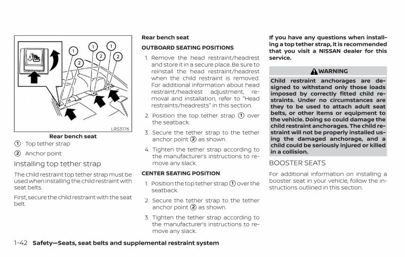
�1 Top tether strap
�2 Anchor point
Installing top tether strapThe child restraint top tether strap must beused when installing the child restraint withseat belts.
First, secure the child restraint with the seatbelt.
Rear bench seat
OUTBOARD SEATING POSITIONS
1. Remove the head restraint/headrestand store it in a secure place. Be sure toreinstall the head restraint/headrestwhen the child restraint is removed.For additional information about headrestraint/headrest adjustment, re-moval and installation, refer to "Headrestraints/headrests" in this section.
2. Position the top tether strap �1 overthe seatback.
3. Secure the tether strap to the tetheranchor point �2 as shown.
4. Tighten the tether strap according tothe manufacturer’s instructions to re-move any slack.
CENTER SEATING POSITION
1. Position the top tether strap �1 over theseatback.
2. Secure the tether strap to the tetheranchor point �2 as shown.
3. Tighten the tether strap according tothe manufacturer’s instructions to re-move any slack.
If you have any questions when install-ing a top tether strap, it is recommendedthat you visit a NISSAN dealer for thisservice.
WARNINGChild restraint anchorages are de-signed to withstand only those loadsimposed by correctly fitted child re-straints. Under no circumstances arethey to be used to attach adult seatbelts, or other items or equipment tothe vehicle. Doing so could damage thechild restraint anchorages. The child re-straint will not be properly installed us-ing the damaged anchorage, and achild could be seriously injured or killedin a collision.
BOOSTER SEATSFor additional information on installing abooster seat in your vehicle, follow the in-structions outlined in this section.
Rear bench seatLRS3176
1-42 Safety—Seats, seat belts and supplemental restraint system
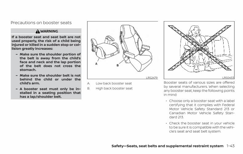
Precautions on booster seats
WARNINGIf a booster seat and seat belt are notused properly, the risk of a child beinginjured or killed in a sudden stop or col-lision greatly increases:
– Make sure the shoulder portion ofthe belt is away from the child’sface and neck and the lap portionof the belt does not cross thestomach.
– Make sure the shoulder belt is notbehind the child or under thechild’s arm.
– A booster seat must only be in-stalled in a seating position thathas a lap/shoulder belt.
A. Low back booster seatB. High back booster seat
Booster seats of various sizes are offeredby several manufacturers. When selectingany booster seat, keep the following pointsin mind:
∙ Choose only a booster seat with a labelcertifying that it complies with FederalMotor Vehicle Safety Standard 213 orCanadian Motor Vehicle Safety Stan-dard 213.
∙ Check the booster seat in your vehicleto be sure it is compatible with the vehi-cle’s seat and seat belt system.
LRS2479 LRS0453
Safety—Seats, seat belts and supplemental restraint system 1-43
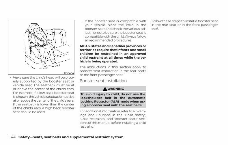
∙ Make sure the child’s head will be prop-erly supported by the booster seat orvehicle seat. The seatback must be ator above the center of the child’s ears.For example, if a low back booster seatis chosen, the vehicle seatback must beat or above the center of the child’s ears.If the seatback is lower than the centerof the child’s ears, a high back boosterseat should be used.
∙ If the booster seat is compatible withyour vehicle, place the child in thebooster seat and check the various ad-justments to be sure the booster seat iscompatible with the child. Always followall recommended procedures.
All U.S. states and Canadian provinces orterritories require that infants and smallchildren be restrained in an approvedchild restraint at all times while the ve-hicle is being operated.
The instructions in this section apply tobooster seat installation in the rear seatsor the front passenger seat.
Booster seat installation
WARNINGTo avoid injury to child, do not use thelap/shoulder belt in the AutomaticLocking Retractor (ALR) mode when us-ing a booster seat with the seat belts.
For additional information, refer to all Warn-ings and Cautions in the “Child safety”,“Child restraints” and “Booster seats” sec-tions of this manual before installing a childrestraint.
Follow these steps to install a booster seatin the rear seat or in the front passengerseat:
LRS0464
1-44 Safety—Seats, seat belts and supplemental restraint system
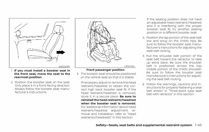
1. If you must install a booster seat inthe front seat, move the seat to therearmost position.
2. Position the booster seat on the seat.Only place it in a front-facing direction.Always follow the booster seat manu-facturer’s instructions.
3. The booster seat should be positionedon the vehicle seat so that it is stable.
If necessary, adjust or remove the headrestraint/headrest to obtain the cor-rect high back booster seat fit. If thehead restraint/headrest is removed,store it in a secure place. Be sure toreinstall the head restraint/headrestwhen the booster seat is removed.For additional information about headrestraint/headrest adjustment, re-moval and installation, refer to "Headrestraints/headrests" in this section.
If the seating position does not havean adjustable head restraint/headrestand it is interfering with the properbooster seat fit, try another seatingposition or a different booster seat.
4. Position the lap portion of the seat beltlow and snug on the child’s hips. Besure to follow the booster seat manu-facturer’s instructions for adjusting theseat belt routing.
5. Pull the shoulder belt portion of theseat belt toward the retractor to takeup extra slack. Be sure the shoulderbelt is positioned across the top,middle portion of the child’s shoulder.Be sure to follow the booster seatmanufacturer’s instructions for adjust-ing the seat belt routing.
6. Follow the warnings, cautions and in-structions for properly fastening a seatbelt shown in “Three-point type seatbelt with retractor” in this section.
WRS0699Front passenger position
LRS0454
Safety—Seats, seat belts and supplemental restraint system 1-45
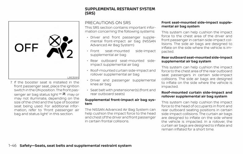
7. If the booster seat is installed in thefront passenger seat, place the ignitionswitch in the ON position. The front pas-senger air bag status light may ormay not illuminate, depending on thesize of the child and the type of boosterseat being used. For additional infor-mation, refer to “Front passenger airbag and status light” in this section.
PRECAUTIONS ON SRSThis SRS section contains important infor-mation concerning the following systems:
∙ Driver and front passenger supple-mental front-impact air bag (NISSANAdvanced Air Bag System)
∙ Front seat-mounted side-impactsupplemental air bag
∙ Rear outboard seat-mounted side-impact supplemental air bag
∙ Roof-mounted curtain side-impact androllover supplemental air bag
∙ Driver and passenger supplementalknee air bag
∙ Seat belt with pretensioner(s) (front andrear outboard seats)
Supplemental front-impact air bag sys-tem
The NISSAN Advanced Air Bag System canhelp cushion the impact force to the headand chest of the driver and front passengerin certain frontal collisions.
Front seat-mounted side-impact supple-mental air bag system
This system can help cushion the impactforce to the chest area of the driver andfront passenger in certain side-impact col-lisions. The side air bags are designed toinflate on the side where the vehicle is im-pacted.
Rear outboard seat-mounted side-impactsupplemental air bag system
This system can help cushion the impactforce to the chest area of the rear outboardseat passengers in certain side-impactcollisions. The side air bags are designedto inflate on the side where the vehicle isimpacted.
Roof-mounted curtain side-impact androllover supplemental air bag system
This system can help cushion the impactforce to the head of occupants in front andrear outboard seating positions in certainside-impact collisions. The curtain air bagsare designed to inflate on the side wherethe vehicle is impacted. In a rollover, thecurtain air bags are designed to inflate andremain inflated for a short time.
LRS3091
SUPPLEMENTAL RESTRAINT SYSTEM(SRS)
1-46 Safety—Seats, seat belts and supplemental restraint system
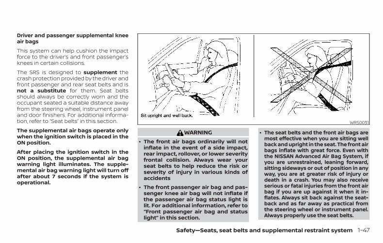
Driver and passenger supplemental kneeair bags
This system can help cushion the impactforce to the driver’s and front passenger’sknees in certain collisions.
The SRS is designed to supplement thecrash protection provided by the driver andfront passenger and rear seat belts and isnot a substitute for them. Seat beltsshould always be correctly worn and theoccupant seated a suitable distance awayfrom the steering wheel, instrument paneland door finishers. For additional informa-tion, refer to “Seat belts” in this section.
The supplemental air bags operate onlywhen the ignition switch is placed in theON position.
After placing the ignition switch in theON position, the supplemental air bagwarning light illuminates. The supple-mental air bag warning light will turn offafter about 7 seconds if the system isoperational.
WARNING∙ The front air bags ordinarily will not
inflate in the event of a side impact,rear impact, rollover, or lower severityfrontal collision. Always wear yourseat belts to help reduce the risk orseverity of injury in various kinds ofaccidents
∙ The front passenger air bag and pas-senger knee air bag will not inflate ifthe passenger air bag status light islit. For additional information, refer to“Front passenger air bag and statuslight” in this section.
∙ The seat belts and the front air bags aremost effective when you are sitting wellback and upright in the seat. The front airbags inflate with great force. Even withthe NISSAN Advanced Air Bag System, ifyou are unrestrained, leaning forward,sitting sideways or out of position in anyway, you are at greater risk of injury ordeath in a crash. You may also receiveserious or fatal injuries from the front airbag if you are up against it when it in-flates. Always sit back against the seat-back and as far away as practical fromthe steering wheel or instrument panel.Always properly use the seat belts.
WRS0031
Safety—Seats, seat belts and supplemental restraint system 1-47
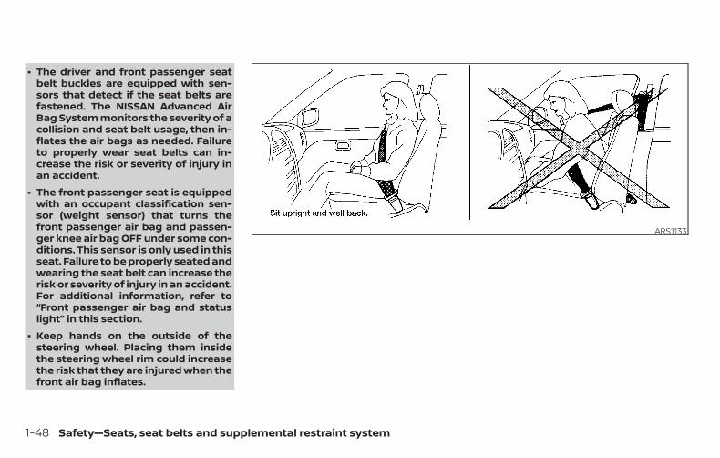
∙ The driver and front passenger seatbelt buckles are equipped with sen-sors that detect if the seat belts arefastened. The NISSAN Advanced AirBag System monitors the severity of acollision and seat belt usage, then in-flates the air bags as needed. Failureto properly wear seat belts can in-crease the risk or severity of injury inan accident.
∙ The front passenger seat is equippedwith an occupant classification sen-sor (weight sensor) that turns thefront passenger air bag and passen-ger knee air bag OFF under some con-ditions. This sensor is only used in thisseat. Failure to be properly seated andwearing the seat belt can increase therisk or severity of injury in an accident.For additional information, refer to“Front passenger air bag and statuslight” in this section.
∙ Keep hands on the outside of thesteering wheel. Placing them insidethe steering wheel rim could increasethe risk that they are injured when thefront air bag inflates.
ARS1133
1-48 Safety—Seats, seat belts and supplemental restraint system
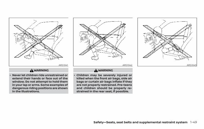
WARNING∙ Never let children ride unrestrained or
extend their hands or face out of thewindow. Do not attempt to hold themin your lap or arms. Some examples ofdangerous riding positions are shownin the illustrations.
WARNING∙ Children may be severely injured or
killed when the front air bags, side airbags or curtain air bags inflate if theyare not properly restrained. Pre-teensand children should be properly re-strained in the rear seat, if possible.
ARS1041 ARS1042 ARS1043
Safety—Seats, seat belts and supplemental restraint system 1-49
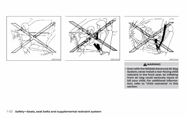
WARNING∙ Even with the NISSAN Advanced Air Bag
System, never install a rear-facing childrestraint in the front seat. An inflatingfront air bag could seriously injure orkill your child. For additional informa-tion, refer to “Child restraints” in thissection.
ARS1044 ARS1045 ARS1046
1-50 Safety—Seats, seat belts and supplemental restraint system
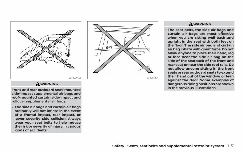
WARNINGFront and rear outboard seat-mountedside-impact supplemental air bags androof-mounted curtain side-impact androllover supplemental air bags:
∙ The side air bags and curtain air bagsordinarily will not inflate in the eventof a frontal impact, rear impact, orlower severity side collision. Alwayswear your seat belts to help reducethe risk or severity of injury in variouskinds of accidents.
WARNING∙ The seat belts, the side air bags and
curtain air bags are most effectivewhen you are sitting well back andupright in the seat with both feet onthe floor. The side air bag and curtainair bag inflate with great force. Do notallow anyone to place their hand, legor face near the side air bag on theside of the seatback of the front andrear seat or near the side roof rails. Donot allow anyone sitting in the frontseats or rear outboard seats to extendtheir hand out of the window or leanagainst the door. Some examples ofdangerous riding positions are shownin the previous illustrations.
WRS0431 LRS3119
Safety—Seats, seat belts and supplemental restraint system 1-51
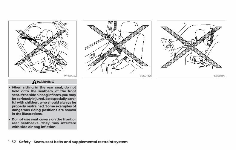
WARNING∙ When sitting in the rear seat, do not
hold onto the seatback of the frontseat. If the side air bag inflates, you maybe seriously injured. Be especially care-ful with children, who should always beproperly restrained. Some examples ofdangerous riding positions are shownin the illustrations.
∙ Do not use seat covers on the front orrear seatbacks. They may interferewith side air bag inflation.
WRS0032 SSS0162 SSS0159
1-52 Safety—Seats, seat belts and supplemental restraint system
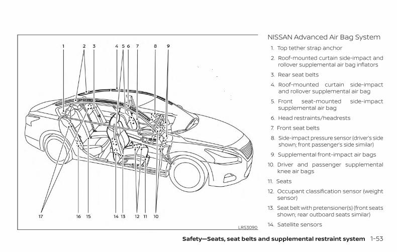
NISSAN Advanced Air Bag System1. Top tether strap anchor
2. Roof-mounted curtain side-impact androllover supplemental air bag inflators
3. Rear seat belts
4. Roof-mounted curtain side-impactand rollover supplemental air bag
5. Front seat-mounted side-impactsupplemental air bag
6. Head restraints/headrests
7. Front seat belts
8. Side-impact pressure sensor (driver’s sideshown; front passenger’s side similar)
9. Supplemental front-impact air bags
10. Driver and passenger supplementalknee air bags
11. Seats
12. Occupant classification sensor (weightsensor)
13. Seat belt with pretensioner(s) (front seatsshown; rear outboard seats similar)
14. Satellite sensorsLRS3090
Safety—Seats, seat belts and supplemental restraint system 1-53
15. LATCH (Lower Anchors and Tethers forCHildren) system
16. Satellite sensors
17. Rear outboard seat-mounted side-impact supplemental air bags
WARNINGTo ensure proper operation of thepassenger’s NISSAN Advanced Air BagSystem, please observe the followingitems.
∙ Do not allow a passenger in the rearseat to push or pull on the seatbackpocket.
∙ Do not place heavy loads heavier than9.1 lbs. (4 kg) on the seatback, headrestraint/headrest or in the seatbackpocket.
∙ Make sure that there is nothing press-ing against the rear of the seatback,such as a child restraint installed inthe rear seat or an object stored onthe floor.
∙ Make sure that there is no objectplaced under the front passengerseat.
∙ Make sure that there is no objectplaced between the seat cushion andcenter console or between the seatcushion and the door.
∙ If a forward facing child restraint isinstalled in the front passenger seat,do not position the front passengerseat so the child restraint contacts theinstrument panel. If the child restraintdoes contact the instrument panel,the system may determine the seat isoccupied and the passenger air bagand passenger knee air bag may de-ploy in a collision. Also the front pas-senger air bag status light may notilluminate. For additional informationabout installing and using child re-straints, refer to "Child restraints" inthis section.
∙ Confirm the operating condition withthe front passenger air bag statuslight.
∙ If you notice that the front passengerair bag status light is not operating asdescribed in this section, get the oc-cupant classification system checked.It is recommended that you visit aNISSAN dealer for this service.
∙ Until you have confirmed with adealer that your passenger seat occu-pant classification system is workingproperly, position the occupants inthe rear seating positions.
∙ Do not position the front passengerseat so it contacts the rear seat. If thefront seat does contact the rear seat,the air bag system may determine asensor malfunction has occurred andthe front passenger air bag statuslight may illuminate and the supple-mental air bag warning light mayflash.
This vehicle is equipped with the NISSANAdvanced Air Bag System for the driver andfront passenger seats. This system is de-signed to meet certification requirementsunder U.S. regulations. It is also permitted inCanada. However, all of the information,cautions and warnings in this manualstill apply and must be followed.
The driver supplemental front-impact airbag is located in the center of the steeringwheel. The front passenger supplementalfront-impact air bag is mounted in thedashboard above the glove box. The frontair bags are designed to inflate in higherseverity frontal collisions, although they
1-54 Safety—Seats, seat belts and supplemental restraint system
may inflate if the forces in another type ofcollision are similar to those of a higherseverity frontal impact. They may not in-flate in certain frontal collisions. Vehicledamage (or lack of it) is not always an indi-cation of proper front air bag system op-eration.
The NISSAN Advanced Air Bag Systemmonitors information from the crash zonesensor, the Air bag Control Unit (ACU), seatbelt buckle sensors and occupant classifi-cation sensor (weight sensor). Inflator op-eration is based on the severity of a colli-sion and seat belt usage for the driver. Forthe front passenger, the occupant classifi-cation sensor is also monitored. Based oninformation from the sensor, only one frontair bag may inflate in a crash, depending onthe crash severity and whether the frontoccupants are belted or unbelted. Addi-tionally, the front passenger air bag andpassenger knee air bag may be automati-cally turned off under some conditions, de-pending on the weight detected on thefront passenger seat and how the seat beltis used. If the front passenger air bag andpassenger knee air bag are OFF, the frontpassenger air bag status light will be illumi-nated. For additional information, refer to“Front passenger air bag and status light” in
this section. One front air bag inflating doesnot indicate improper performance of thesystem.
If you have any questions about your airbag system, it is recommended that youvisit a NISSAN dealer to obtain informationabout the system. If you are consideringmodification of your vehicle due to a dis-ability, you may also contact NISSAN. Con-tact information is contained in the front ofthis Owner’s Manual.
When a front air bag inflates, a fairly loudnoise may be heard, followed by the re-lease of smoke. This smoke is not harmfuland does not indicate a fire. Care should betaken to not inhale it, as it may cause irrita-tion and choking. Those with a history of abreathing condition should get fresh airpromptly.
Front air bags, along with the use of seatbelts, help to cushion the impact force onthe face and chest of the front occupants.They can help save lives and reduce seri-ous injuries. However, an inflating front airbag may cause facial abrasions or otherinjuries. Front air bags do not provide re-straint to the lower body.
Even with NISSAN Advanced Air Bags, seatbelts should be correctly worn and thedriver and front passenger seated uprightas far as practical away from the steeringwheel or instrument panel. The front airbags inflate quickly in order to help protectthe front occupants. Because of this, theforce of the front air bag inflating can in-crease the risk of injury if the occupant istoo close to, or is against, the front air bagmodule during inflation.
The front air bags deflate quickly after acollision.
The front air bags operate only when theignition switch is placed in the ON posi-tion.
After placing the ignition switch in theON position, the supplemental air bagwarning light illuminates. The supple-mental air bag warning light will turn offafter about 7 seconds if the system isoperational.
Safety—Seats, seat belts and supplemental restraint system 1-55
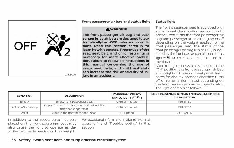
Front passenger air bag and status light
WARNINGThe front passenger air bag and pas-senger knee air bag are designed to au-tomatically turn OFF under some condi-tions. Read this section carefully tolearn how it operates. Proper use of theseat, seat belt, and child restraints isnecessary for most effective protec-tion. Failure to follow all instructions inthis manual concerning the use ofseats, seat belts, and child restraintscan increase the risk or severity of in-jury in an accident.
Status light
The front passenger seat is equipped withan occupant classification sensor (weightsensor) that turns the front passenger airbag and passenger knee air bag on or offdepending on the weight applied to thefront passenger seat. The status of thefront passenger air bag (ON or OFF) is indi-cated by the front passenger air bag statuslight which is located on the instru-ment panel.After the ignition switch is placed in the"ON" position, the front passenger air bagstatus light on the instrument panel illumi-nates for about 7 seconds and then turnsoff or remains illuminated depending onthe front passenger seat occupied status.The light operates as follows:
CONDITION DESCRIPTIONPASSENGER AIR BAG
STATUS LIGHT ( )FRONT PASSENGER AIR BAG AND PASSENGER KNEE
AIR BAG STATUSEmpty Empty front passenger seat ON (illuminated) INHIBITED
Nobody/Somebody Bag or Child or Child Restraint or Small Adult infront passenger seat ON (illuminated) INHIBITED
Adult Adult in the front passenger seat OFF (dark) ACTIVATED
In addition to the above, certain objectsplaced on the front passenger seat mayalso cause the light to operate as de-scribed above depending on their weight.
For additional information, refer to “Normaloperation” and “Troubleshooting” in thissection.
LRS3091
1-56 Safety—Seats, seat belts and supplemental restraint system
Front passenger air bag
The front passenger air bag is designed toautomatically turn OFF when the vehicle isoperated under some conditions as de-scribed below in accordance with U.S. regu-lations. If the front passenger air bag is OFF,it will not inflate in a crash. The driver air bagand other air bags in your vehicle are notpart of this system.
The purpose of the regulation is to helpreduce the risk of injury or death from aninflating air bag to certain front passengerseat occupants, such as children, by requir-ing the air bag to be automatically turnedOFF. Certain sensors are used to meet therequirements.
The occupant classification sensor in thisvehicle is a weight sensor. It is designed todetect an occupant and objects on theseat by weight. For example, if a child is inthe front passenger seat, the NISSAN Ad-vanced Air Bag System is designed to turnthe front passenger air bag OFF in accor-dance with the regulations. Also, if a childrestraint of the type specified in the regula-tions is on the seat, its weight and thechild’s weight can be detected and causethe air bag to turn OFF.
Front passenger seat adult occupants whoare properly seated and using the seat beltas outlined in this manual should notcause the front passenger air bag and pas-senger knee air bag to be automaticallyturned OFF. For small adults it may beturned OFF, however if the occupant takeshis/her weight off the seat cushion (for ex-ample, by not sitting upright, by sitting onan edge of the seat, or by otherwise beingout of position), this could cause the sensorto turn the air bag OFF. Always be sure to beseated and wearing the seat belt properlyfor the most effective protection by theseat belt and supplemental air bag.
NISSAN recommends that pre-teens andchildren be properly restrained in a rearseat. NISSAN also recommends that ap-propriate child restraints and boosterseats be properly installed in a rear seat. Ifthis is not possible, the occupant classifica-tion sensor is designed to operate as de-scribed above to turn the front passengerair bag and passenger knee air bag OFF forspecified child restraints as required by theregulations. Failing to properly secure childrestraints and to use the ALR mode mayallow the restraint to tip or move in a colli-sion or sudden stop. This can also result inthe passenger air bag and passenger kneeair bag inflating in a crash instead of being
OFF. For additional information aboutproper use and installation, refer to “Childrestraints” in this section.
If the front passenger seat is not occupied,the front passenger air bag and passengerknee air bag are designed not to inflate in acrash. However, heavy objects placed onthe seat could result in air bag inflation,because of the object’s weight detected bythe occupant classification sensor. Otherconditions could also result in air bag infla-tion, such as if a child is standing on theseat, or if two children are on the seat, con-trary to the instructions in this manual. Al-ways be sure that you and all vehicle occu-pants are seated and restrained properly.
Using the front passenger air bag statuslight, you can monitor when the front pas-senger air bag and passenger knee air bagare automatically turned OFF.
If an adult occupant is in the seat but thefront passenger air bag status light is illu-minated (indicating that the front passen-ger air bag and passenger knee air bag areOFF), it could be that the person is a smalladult, or is not sitting on the seat properlyor not using the seat belt properly.
If a child restraint must be used in the frontseat, the front passenger air bag status
Safety—Seats, seat belts and supplemental restraint system 1-57
light may or may not be illuminated, de-pending on the size of the child and thetype of child restraint being used. If the airbag status light is not illuminated (indicat-ing that the air bag might inflate in a crash),it could be that the child restraint or seatbelt is not being used properly. Make surethat the child restraint is installed properly,the seat belt is used properly and the occu-pant is positioned properly. If the air bagstatus light is still not illuminated, reposi-tion the occupant or child restraint in a rearseat.
If the front passenger air bag status lightwill not illuminate even though you believethat the child restraint, the seat belts andthe occupant are properly positioned, it isrecommended that you take your vehicleto a NISSAN dealer. A NISSAN dealer cancheck system status by using a specialtool. However, until you have confirmedwith a dealer that your air bag is workingproperly, reposition the occupant or childrestraint in a rear seat.
The NISSAN Advanced Air Bag System andfront passenger air bag status light willtake a few seconds to register a change inthe front passenger seat status. This is nor-mal system operation and does not indi-cate a malfunction.
If a malfunction occurs in the front passen-ger air bag system, the supplemental airbag warning light , located in the me-ter and gauges area of the instrumentpanel, will be illuminated (blinking orsteadily lit). Have the system checked. It isrecommended that you visit a NISSANdealer for this service.
Normal operationIn order for the occupant classificationsensor system to classify the front passen-ger based on weight, please follow the pre-cautions and steps outlined below:
Precautions
∙ Make sure that there are no objectsweighing over 9.1 lbs. (4 kg) hanging onthe seat or placed in the seatbackpocket.
∙ Make sure that a child restraint or otherobject is not pressing against the rearof the seatback.
∙ Make sure that a rear passenger is notpushing or pulling on the back of thefront passenger seat.
∙ Make sure that the front passengerseat or seatback is not forced backagainst an object on the seat or floorbehind it.
∙ Make sure that there is no object placedunder the front passenger seat.
Steps
1. Adjust the seat as outlined in the “Seats”section of this manual. Sit upright, lean-ing against the seatback, and centeredon the seat cushion with your feet com-fortably extended to the floor.
2. Make sure there are no objects on yourlap.
3. Fasten the seat belt as outlined in the“Seat belts” section of this manual.Front passenger seat belt buckle sta-tus is monitored by the occupant clas-sification system, and is used as an in-put to determine occupancy status. So,it is highly recommended that the frontpassenger fasten their seat belt.
4. Remain in this position for 30 secondsallowing the system to classify thefront passenger before the vehicle isput into motion.
5. Ensure proper classification by check-ing the front passenger air bag statuslight.
1-58 Safety—Seats, seat belts and supplemental restraint system
NOTE:
This vehicle’s occupant classificationsensor system generally keeps the clas-sification locked during driving, so it isimportant that you confirm that thefront passenger is properly classifiedprior to driving. However, the occupantclassification sensor may recalculate theweight of the occupant under some con-ditions (both while driving and whenstopped), so front passenger seat occu-pants should continue to remain seatedas outlined above.
Troubleshooting
If you think the front passenger air bagstatus light is incorrect:
1. If the light is ON with an adult occupyingthe front passenger seat:
∙ Occupant is a small adult — the air baglight is functioning as intended. Thefront passenger air bag and passengerknee air bag are suppressed.
However, if the occupant is not a smalladult, then this may be due to the followingconditions that may be interfering with theweight sensors:
∙ Occupant is not sitting upright, leaningagainst the seatback, and centered onthe seat cushion with his/her feet com-fortably extended to the floor.
∙ A child restraint or other object pressingagainst the rear of the seatback.
∙ A rear passenger pushing or pulling onthe back of the front passenger seat.
∙ Forcing the front seat or seatbackagainst an object on the seat or floorbehind it.
∙ An object placed under the front pas-senger seat.
∙ An object placed between the seatcushion and center console or betweenthe seat cushion and the door.
If the vehicle is moving, please come to astop when it is safe to do so. Check andcorrect any of the above conditions. Re-start the vehicle and wait 1 minute.
NOTE:
A system check will be performed duringwhich the front passenger air bag statuslight will remain lit for about 7 secondsinitially.
If the light is still ON after this, the personshould be advised not to ride in the frontpassenger seat and the vehicle should bechecked as soon as possible. It is recom-mended that you visit a NISSAN dealer forthis service.
2. If the light is OFF with a small adult,child or child restraint occupying thefront passenger seat.
This may be due to the following con-ditions that may be interfering with theweight sensors:
∙ Small adult or child is not sitting upright,leaning against the seatback, and cen-tered on the seat cushion with his/herfeet comfortably extended to the floor.
∙ The child restraint is not properly in-stalled, as outlined in the “Child re-straints” section of this manual.
∙ An object weighing over 9.1 lbs. (4 kg)hanging on the seat or placed in theseatback pocket.
Safety—Seats, seat belts and supplemental restraint system 1-59
∙ A child restraint or other object pressingagainst the rear of the seatback.
∙ A rear passenger pushing or pulling onthe back of the front passenger seat.
∙ Forcing the front seat or seatbackagainst an object on the seat or floorbehind it.
∙ An object placed under the front pas-senger seat.
∙ An object placed between the seatcushion and center console.
If the vehicle is moving, please come to astop when it is safe to do so. Check andcorrect any of the above conditions. Re-start the vehicle and wait 1 minute.
NOTE:
A system check will be performed duringwhich the front passenger air bag statuslight will remain lit for about 7 secondsinitially.
If the light is still OFF after this, the smalladult, child or child restraint should be re-positioned in the rear seat and the vehicleshould be checked as soon as possible. It isrecommended that you visit a NISSANdealer for this service.
3. If the light is OFF with no front passen-ger and no objects on the front pas-senger seat, the vehicle should bechecked. It is recommended that youvisit a NISSAN dealer as soon as pos-sible.
Other supplemental front-impact airbag precautions
WARNING∙ Do not place any objects on the steer-
ing wheel pad or on the instrumentpanel. Also, do not place any objectsbetween any occupant and the steer-ing wheel or instrument panel. Suchobjects may become dangerous pro-jectiles and cause injury if the front airbags inflate.
∙ Immediately after inflation, severalfront air bag system components willbe hot. Do not touch them; you mayseverely burn yourself.
∙ No unauthorized changes should bemade to any components or wiring ofthe supplemental air bag system. Thisis to prevent accidental inflation ofthe supplemental air bag or damageto the supplemental air bag system.
∙ Do not make unauthorized changesto your vehicle’s electrical system,suspension system or front end struc-ture. This could affect proper opera-tion of the front air bag system.
∙ Tampering with the front air bag sys-tem may result in serious personal in-jury. Tampering includes changes tothe steering wheel and the instru-ment panel assembly by placing ma-terial over the steering wheel pad andabove the instrument panel or byinstalling additional trim materialaround the air bag system.
∙ Removing or modifying the front pas-senger seat may affect the function ofthe air bag system and result in seri-ous personal injury.
1-60 Safety—Seats, seat belts and supplemental restraint system
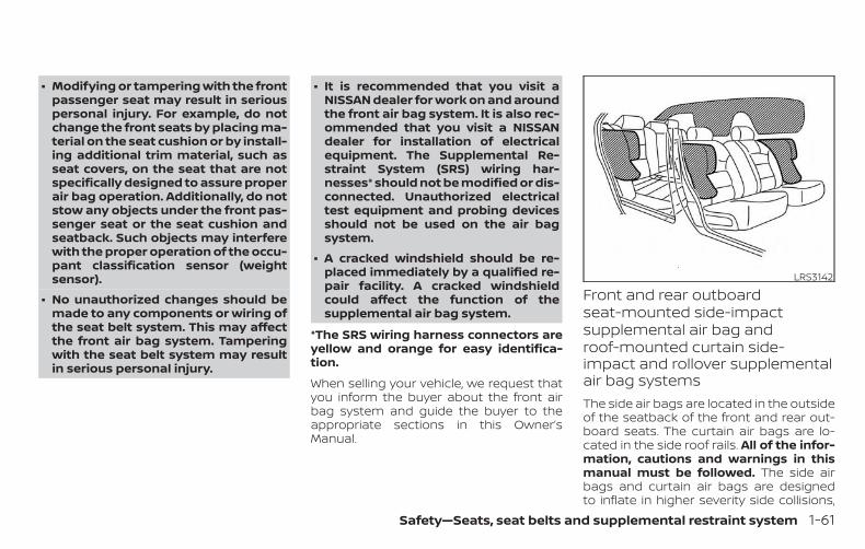
∙ Modifying or tampering with the frontpassenger seat may result in seriouspersonal injury. For example, do notchange the front seats by placing ma-terial on the seat cushion or by install-ing additional trim material, such asseat covers, on the seat that are notspecifically designed to assure properair bag operation. Additionally, do notstow any objects under the front pas-senger seat or the seat cushion andseatback. Such objects may interferewith the proper operation of the occu-pant classification sensor (weightsensor).
∙ No unauthorized changes should bemade to any components or wiring ofthe seat belt system. This may affectthe front air bag system. Tamperingwith the seat belt system may resultin serious personal injury.
∙ It is recommended that you visit aNISSAN dealer for work on and aroundthe front air bag system. It is also rec-ommended that you visit a NISSANdealer for installation of electricalequipment. The Supplemental Re-straint System (SRS) wiring har-nesses* should not be modified or dis-connected. Unauthorized electricaltest equipment and probing devicesshould not be used on the air bagsystem.
∙ A cracked windshield should be re-placed immediately by a qualified re-pair facility. A cracked windshieldcould affect the function of thesupplemental air bag system.
*The SRS wiring harness connectors areyellow and orange for easy identifica-tion.
When selling your vehicle, we request thatyou inform the buyer about the front airbag system and guide the buyer to theappropriate sections in this Owner’sManual.
Front and rear outboardseat-mounted side-impactsupplemental air bag androof-mounted curtain side-impact and rollover supplementalair bag systemsThe side air bags are located in the outsideof the seatback of the front and rear out-board seats. The curtain air bags are lo-cated in the side roof rails. All of the infor-mation, cautions and warnings in thismanual must be followed. The side airbags and curtain air bags are designedto inflate in higher severity side collisions,
LRS3142
Safety—Seats, seat belts and supplemental restraint system 1-61
although they may inflate if the forces inanother type of collision are similar tothose of a higher severity impact. They aredesigned to inflate on the side where thevehicle is impacted. They may not inflate incertain side collisions.
Curtain air bags are also designed to inflatein certain types of rollover collisions or nearrollovers. As a result, certain vehicle move-ments (for example, during severe off-roading) may cause the curtain air bags toinflate.
Vehicle damage (or lack of it) is not alwaysan indication of proper side air bag andcurtain air bag operation.
When the side air bags and curtain air bagsinflate, a fairly loud noise may be heard,followed by the release of smoke. Thissmoke is not harmful and does not indi-cate a fire. Care should be taken not toinhale it, as it may cause irritation andchoking. Those with a history of a breath-ing condition should get fresh air promptly.
Side air bags, along with the use of seatbelts, help to cushion the impact force onthe chest and pelvic area of the front andrear outboard occupants. Curtain air bagshelp to cushion the impact force to thehead of occupants in the front and rear
outboard seating positions. They can helpsave lives and reduce serious injuries. How-ever, an inflating side air bag and curtain airbag may cause abrasions or other injuries.Side air bags and curtain air bags do notprovide restraint to the lower body.
The seat belts should be correctly wornand the driver, front passenger and rearoutboard occupants seated upright as faras practical away from the side air bag.Rear seat passengers should be seated asfar away as practical from the door finish-ers and side roof rails. The side air bags andcurtain air bags inflate quickly in order tohelp protect the occupants. Because ofthis, the force of the side air bag and curtainair bag inflating can increase the risk ofinjury if the occupant is too close to, or isagainst, these air bag modules during in-flation. The side air bag will deflate quicklyafter the collision is over.
The curtain air bag will remain inflated for ashort time.
The side air bags and curtain air bagsoperate only when the ignition switch isplaced in the ON position.
After placing the ignition switch in theON position, the supplemental air bagwarning light illuminates. The supple-
mental air bag warning light will turn offafter about 7 seconds if the system isoperational.
WARNING∙ Do not place any objects near the
seatback of the front and rear seats.Also, do not place any objects (an um-brella, bag, etc.) between the frontand rear door finisher and the frontand rear seat. Such objects may be-come dangerous projectiles andcause injury if a side air bag inflate.
∙ Right after inflation, several side airbag and curtain air bag system com-ponents will be hot. Do not touchthem; you may severely burn yourself.
∙ No unauthorized changes should bemade to any components or wiring ofthe side air bag and curtain air bagsystems. This is to prevent damage toor accidental inflation of the side airbag and curtain air bag or damage tothe side air bag and curtain air bagsystems.
1-62 Safety—Seats, seat belts and supplemental restraint system
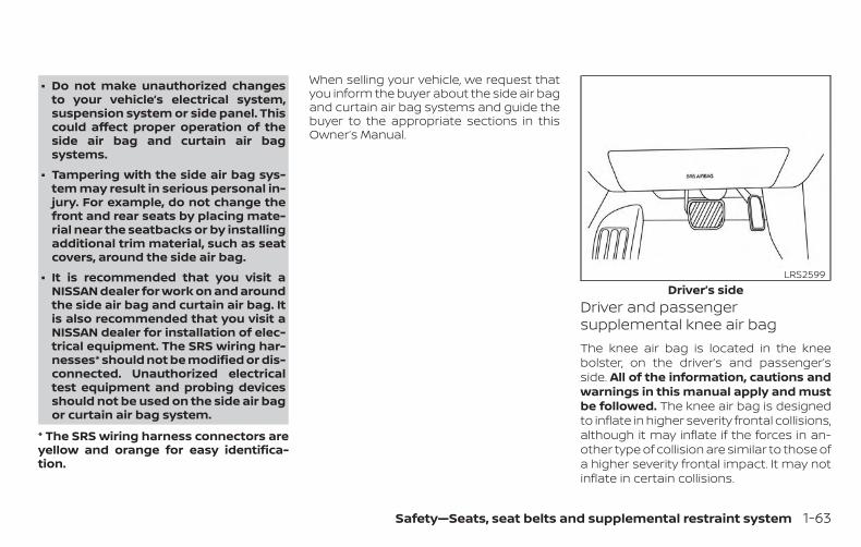
∙ Do not make unauthorized changesto your vehicle’s electrical system,suspension system or side panel. Thiscould affect proper operation of theside air bag and curtain air bagsystems.
∙ Tampering with the side air bag sys-tem may result in serious personal in-jury. For example, do not change thefront and rear seats by placing mate-rial near the seatbacks or by installingadditional trim material, such as seatcovers, around the side air bag.
∙ It is recommended that you visit aNISSAN dealer for work on and aroundthe side air bag and curtain air bag. Itis also recommended that you visit aNISSAN dealer for installation of elec-trical equipment. The SRS wiring har-nesses* should not be modified or dis-connected. Unauthorized electricaltest equipment and probing devicesshould not be used on the side air bagor curtain air bag system.
* The SRS wiring harness connectors areyellow and orange for easy identifica-tion.
When selling your vehicle, we request thatyou inform the buyer about the side air bagand curtain air bag systems and guide thebuyer to the appropriate sections in thisOwner’s Manual.
Driver and passengersupplemental knee air bagThe knee air bag is located in the kneebolster, on the driver’s and passenger’sside. All of the information, cautions andwarnings in this manual apply and mustbe followed. The knee air bag is designedto inflate in higher severity frontal collisions,although it may inflate if the forces in an-other type of collision are similar to those ofa higher severity frontal impact. It may notinflate in certain collisions.
Driver’s sideLRS2599
Safety—Seats, seat belts and supplemental restraint system 1-63
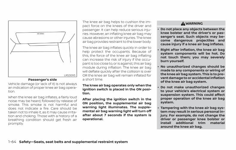
Vehicle damage (or lack of it) is not alwaysan indication of proper knee air bag opera-tion.
When the knee air bag inflates, a fairly loudnoise may be heard, followed by release ofsmoke. This smoke is not harmful anddoes not indicate a fire. Care should betaken not to inhale it, as it may cause irrita-tion and choking. Those with a history of abreathing condition should get fresh airpromptly.
The knee air bag helps to cushion the im-pact force on the knees of the driver andpassenger. It can help reduce serious inju-ries. However, an inflating knee air bag maycause abrasions or other injuries. The kneeair bag provides restraint to the lower body.
The knee air bag inflates quickly in order tohelp protect the occupants. Because ofthis, the force of the knee air bag inflatingcan increase the risk of injury if the occu-pant is too close to, or is against, this air bagmodule during inflation. The knee air bagwill deflate quickly after the collision is overOR the knee air bag will remain inflated fora short time.
The knee air bag operates only when theignition switch is placed in the ON posi-tion.
After placing the ignition switch in theON position, the supplemental air bagwarning light illuminates. The supple-mental air bag warning light will turn offafter about 7 seconds if the system isoperational.
WARNING∙ Do not place any objects between the
knee bolster and the driver’s or pas-senger’s seat. Such objects may be-come dangerous projectiles andcause injury if a knee air bag inflates.
∙ Right after inflation, the knee air bagsystem components will be hot. Donot touch them; you may severelyburn yourself.
∙ No unauthorized changes should bemade to any components or wiring ofthe knee air bag system. This is to pre-vent damage to or accidental inflationof the knee air bag system.
∙ Do not make unauthorized changesto your vehicle’s electrical system orsuspension system. This could affectproper operation of the knee air bagsystem.
∙ Tampering with the knee air bag sys-tem may result in serious personal in-jury. For example, do not change thedriver or passenger knee bolster orinstall additional trim materialaround the knee air bag.
Passenger’s sideLRS3093
1-64 Safety—Seats, seat belts and supplemental restraint system
∙ It is recommended that you visit aNISSAN dealer for work on and aroundthe knee air bag. It is also recom-mended that you visit a NISSAN dealerfor installation of electrical equip-ment. The SRS wiring harnesses*should not be modified or discon-nected. Unauthorized electrical testequipment and probing devicesshould not be used on the knee airbag system.
*The SRS wiring harness or connectorsare yellow or orange for easy identifica-tion.
When selling your vehicle, we request thatyou inform the buyer about the knee airbag system and guide the buyer to theappropriate sections in this manual.
Seat belt with pretensioner(s)(front and rear outboard seats)
WARNING∙ The pretensioner(s) cannot be reused
after activation. They must be re-placed together with the retractorand buckle as a unit.
∙ If the vehicle becomes involved in acollision but pretensioner(s) are notactivated, be sure to have the preten-sioner system checked and, if neces-sary, replaced. It is recommended thatyou visit a NISSAN dealer for thisservice.
∙ No unauthorized changes should bemade to any components or wiring ofthe pretensioner system. This is toprevent damage to or accidental acti-vation of the pretensioner(s). Tamper-ing with the pretensioner system mayresult in serious personal injury.
∙ It is recommended that you visit aNISSAN dealer for work on and aroundthe pretensioner system. It is also rec-ommended that you visit a NISSANdealer for installation of electricalequipment. Unauthorized electricaltest equipment and probing devicesshould not be used on the preten-sioner system.
∙ If you need to dispose of the preten-sioner(s) or scrap the vehicle, it is rec-ommended that you visit a NISSANdealer for this service. Incorrect dis-posal procedures could cause per-sonal injury.
The pretensioner system may activatewith the supplemental air bag system incertain types of collisions. Working with theseat belt retractor, the pretensioner(s) helptighten the seat belt when the vehicle be-comes involved in certain types of colli-sions, helping to restrain front and rear out-board seat occupants.
The pretensioner(s) are encased within theseat belt retractor and to the seat belt an-chor affixed to the floor of the vehicle.These seat belts are used the same way asconventional seat belts.
Safety—Seats, seat belts and supplemental restraint system 1-65
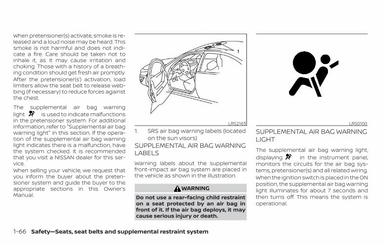
When pretensioner(s) activate, smoke is re-leased and a loud noise may be heard. Thissmoke is not harmful and does not indi-cate a fire. Care should be taken not toinhale it, as it may cause irritation andchoking. Those with a history of a breath-ing condition should get fresh air promptly.After the pretensioner(s’) activation, loadlimiters allow the seat belt to release web-bing (if necessary) to reduce forces againstthe chest.
The supplemental air bag warninglight is used to indicate malfunctionsin the pretensioner system. For additionalinformation, refer to "Supplemental air bagwarning light" in this section. If the opera-tion of the supplemental air bag warninglight indicates there is a malfunction, havethe system checked. It is recommendedthat you visit a NISSAN dealer for this ser-vice.When selling your vehicle, we request thatyou inform the buyer about the preten-sioner system and guide the buyer to theappropriate sections in this Owner’sManual.
1. SRS air bag warning labels (locatedon the sun visors)
SUPPLEMENTAL AIR BAG WARNINGLABELSWarning labels about the supplementalfront-impact air bag system are placed inthe vehicle as shown in the illustration.
WARNINGDo not use a rear-facing child restrainton a seat protected by an air bag infront of it. If the air bag deploys, it maycause serious injury or death.
SUPPLEMENTAL AIR BAG WARNINGLIGHTThe supplemental air bag warning light,displaying in the instrument panel,monitors the circuits for the air bag sys-tems, pretensioner(s) and all related wiring.When the ignition switch is placed in the ONposition, the supplemental air bag warninglight illuminates for about 7 seconds andthen turns off. This means the system isoperational.
LRS2163 LRS0100
1-66 Safety—Seats, seat belts and supplemental restraint system
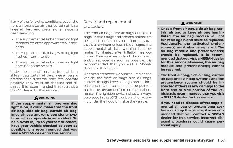
If any of the following conditions occur, thefront air bag, side air bag, curtain air bag,knee air bag and pretensioner systemsneed servicing:
∙ The supplemental air bag warning lightremains on after approximately 7 sec-onds.
∙ The supplemental air bag warning lightflashes intermittently.
∙ The supplemental air bag warning lightdoes not come on at all.
Under these conditions, the front air bag,side air bag, curtain air bag, knee air bag orpretensioner systems may not operateproperly. They must be checked and re-paired. It is recommended that you visit aNISSAN dealer for this service.
WARNINGIf the supplemental air bag warninglight is on, it could mean that the frontair bag, side air bag, curtain air bag,knee air bag and/or pretensioner sys-tems will not operate in an accident. Tohelp avoid injury to yourself or others,have your vehicle checked as soon aspossible. It is recommended that youvisit a NISSAN dealer for this service.
Repair and replacementprocedureThe front air bags, side air bags, curtain airbags, knee air bags and pretensioner(s) aredesigned to inflate on a one-time-only ba-sis. As a reminder, unless it is damaged, thesupplemental air bag warning light re-mains illuminated after inflation has oc-curred. These systems should be repairedand/or replaced as soon as possible. It isrecommended that you visit a NISSANdealer for this service.
When maintenance work is required on thevehicle, the front air bags, side air bags,curtain air bags, knee air bags, pretension-er(s) and related parts should be pointedout to the person performing the mainte-nance. The ignition switch should alwaysbe placed in the LOCK position when work-ing under the hood or inside the vehicle.
WARNING∙ Once a front air bag, side air bag, cur-
tain air bag or knee air bag has in-flated, the air bag module will notfunction again and must be replaced.Additionally, the activated preten-sioner(s) must also be replaced. Theair bag module and pretensioner(s)should be replaced. It is recom-mended that you visit a NISSAN dealerfor this service. However, the air bagmodule and pretensioner(s) cannotbe repaired.
∙ The front air bag, side air bag, curtainair bag, knee air bag systems and thepretensioner system should be in-spected if there is any damage to thefront end or side portion of the ve-hicle. It is recommended that you visita NISSAN dealer for this service.
∙ If you need to dispose of the supple-mental air bag or pretensioner sys-tems or scrap the vehicle, it is recom-mended that you contact a NISSANdealer for this service. Incorrect dis-posal procedures could cause per-sonal injury.
Safety—Seats, seat belts and supplemental restraint system 1-67
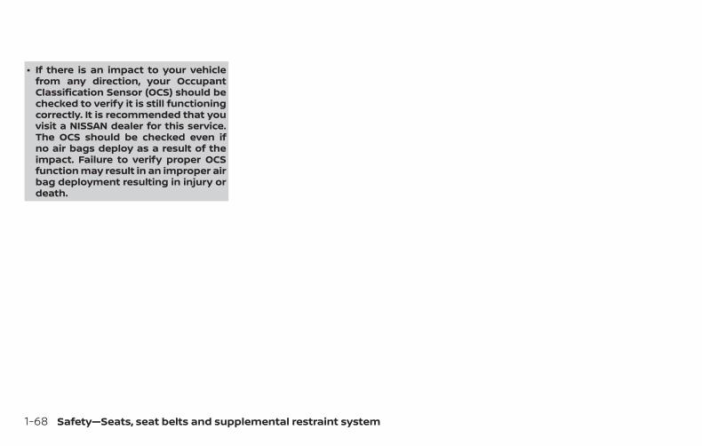
∙ If there is an impact to your vehiclefrom any direction, your OccupantClassification Sensor (OCS) should bechecked to verify it is still functioningcorrectly. It is recommended that youvisit a NISSAN dealer for this service.The OCS should be checked even ifno air bags deploy as a result of theimpact. Failure to verify proper OCSfunction may result in an improper airbag deployment resulting in injury ordeath.
1-68 Safety—Seats, seat belts and supplemental restraint system
MEMO
Safety—Seats, seat belts and supplemental restraint system 1-69
2 Instruments and controls
Instrument panel . . . . . . . . . . . . . . . . . . . . . . . . . . . . . . . . 2-2Meters and gauges. . . . . . . . . . . . . . . . . . . . . . . . . . . . . . 2-4
Speedometer and odometer . . . . . . . . . . . . . . . . . 2-4Tachometer . . . . . . . . . . . . . . . . . . . . . . . . . . . . . . . . . . 2-6Engine coolant temperature gauge . . . . . . . . . . 2-6Fuel gauge . . . . . . . . . . . . . . . . . . . . . . . . . . . . . . . . . . . 2-7Distance To Empty (DTE). . . . . . . . . . . . . . . . . . . . . . 2-7Variable Compression Turbo(if so equipped) . . . . . . . . . . . . . . . . . . . . . . . . . . . . . . . 2-8
Warning lights, indicator lights and audiblereminders . . . . . . . . . . . . . . . . . . . . . . . . . . . . . . . . . . . . . . . 2-9
Checking lights . . . . . . . . . . . . . . . . . . . . . . . . . . . . . . 2-10Warning lights . . . . . . . . . . . . . . . . . . . . . . . . . . . . . . . 2-10Indicator lights . . . . . . . . . . . . . . . . . . . . . . . . . . . . . . 2-15Audible reminders . . . . . . . . . . . . . . . . . . . . . . . . . . . 2-18
Vehicle information display . . . . . . . . . . . . . . . . . . . . . 2-19How to use the vehicle informationdisplay . . . . . . . . . . . . . . . . . . . . . . . . . . . . . . . . . . . . . . 2-19Startup display . . . . . . . . . . . . . . . . . . . . . . . . . . . . . . 2-20Resetting the drive computer. . . . . . . . . . . . . . . . 2-20Oil control system (if so equipped) . . . . . . . . . . . 2-21Settings . . . . . . . . . . . . . . . . . . . . . . . . . . . . . . . . . . . . . 2-21Vehicle information display indicators . . . . . . . 2-29Vehicle information display warnings . . . . . . . . 2-32
Security systems . . . . . . . . . . . . . . . . . . . . . . . . . . . . . . . 2-39Vehicle security system . . . . . . . . . . . . . . . . . . . . . 2-39NISSAN Vehicle Immobilizer System . . . . . . . . . 2-40
Wiper and washer switch . . . . . . . . . . . . . . . . . . . . . . . 2-42Switch operation . . . . . . . . . . . . . . . . . . . . . . . . . . . . 2-42
Rear window and outside mirror(if so equipped) defroster switch. . . . . . . . . . . . . . . . 2-43Headlight and turn signal switch . . . . . . . . . . . . . . . 2-43
Headlight control switch. . . . . . . . . . . . . . . . . . . . . 2-43Daytime Running Lights (DRL) system(Type A) (if so equipped) . . . . . . . . . . . . . . . . . . . . . 2-48LED Daytime Running Lights (DRL)system (Type B) (if so equipped) . . . . . . . . . . . . . 2-48Instrument brightness control. . . . . . . . . . . . . . . 2-49Turn signal switch . . . . . . . . . . . . . . . . . . . . . . . . . . . 2-49Fog light switch (if so equipped) . . . . . . . . . . . . . 2-50
Horn . . . . . . . . . . . . . . . . . . . . . . . . . . . . . . . . . . . . . . . . . . . 2-50Heated seat switches (if so equipped) . . . . . . . . . . 2-51Heated steering wheel switch (if so equipped) . . 2-52Steering Assist switch (for vehicles withProPILOT Assist) (if so equipped) . . . . . . . . . . . . . . . . 2-52E-call (SOS) button (if so equipped) . . . . . . . . . . . . . 2-53Rear Door Alert . . . . . . . . . . . . . . . . . . . . . . . . . . . . . . . . . 2-53Power outlet. . . . . . . . . . . . . . . . . . . . . . . . . . . . . . . . . . . . 2-54
Extended storage switch . . . . . . . . . . . . . . . . . . . . . . . 2-55Storage . . . . . . . . . . . . . . . . . . . . . . . . . . . . . . . . . . . . . . . . 2-56
Front-door pockets. . . . . . . . . . . . . . . . . . . . . . . . . . 2-56Seatback pockets . . . . . . . . . . . . . . . . . . . . . . . . . . . 2-56Glove box. . . . . . . . . . . . . . . . . . . . . . . . . . . . . . . . . . . . 2-57Console box . . . . . . . . . . . . . . . . . . . . . . . . . . . . . . . . . 2-57Overhead sunglasses storage . . . . . . . . . . . . . . . 2-58Cup holders . . . . . . . . . . . . . . . . . . . . . . . . . . . . . . . . . 2-58
Windows . . . . . . . . . . . . . . . . . . . . . . . . . . . . . . . . . . . . . . . 2-60Power windows . . . . . . . . . . . . . . . . . . . . . . . . . . . . . 2-60
Moonroof (if so equipped) . . . . . . . . . . . . . . . . . . . . . . 2-62Power moonroof . . . . . . . . . . . . . . . . . . . . . . . . . . . . 2-62
Interior lights . . . . . . . . . . . . . . . . . . . . . . . . . . . . . . . . . . . 2-64Map lights . . . . . . . . . . . . . . . . . . . . . . . . . . . . . . . . . . . 2-65Personal lights . . . . . . . . . . . . . . . . . . . . . . . . . . . . . . 2-65
Trunk light . . . . . . . . . . . . . . . . . . . . . . . . . . . . . . . . . . . . . . 2-65HomeLink® Universal Transceiver(if so equipped) . . . . . . . . . . . . . . . . . . . . . . . . . . . . . . . . . 2-66
Programming HomeLink® . . . . . . . . . . . . . . . . . . . 2-66Programming HomeLink® for Canadiancustomers and gate openers. . . . . . . . . . . . . . . .2-68Operating the HomeLink® UniversalTransceiver . . . . . . . . . . . . . . . . . . . . . . . . . . . . . . . . . . 2-69Programming trouble-diagnosis . . . . . . . . . . . . 2-69Clearing the programmed information . . . . . . 2-69Reprogramming a single HomeLink®button. . . . . . . . . . . . . . . . . . . . . . . . . . . . . . . . . . . . . . . 2-69If your vehicle is stolen. . . . . . . . . . . . . . . . . . . . . . . 2-70
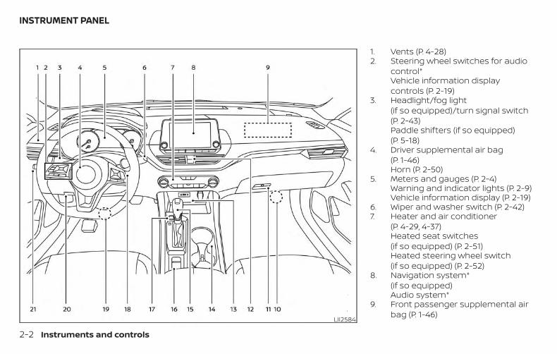
1. Vents (P. 4-28)2. Steering wheel switches for audio
control*Vehicle information displaycontrols (P. 2-19)
3. Headlight/fog light(if so equipped)/turn signal switch(P. 2-43)Paddle shifters (if so equipped)(P. 5-18)
4. Driver supplemental air bag(P. 1-46)Horn (P. 2-50)
5. Meters and gauges (P. 2-4)Warning and indicator lights (P. 2-9)Vehicle information display (P. 2-19)
6. Wiper and washer switch (P. 2-42)7. Heater and air conditioner
(P. 4-29, 4-37)Heated seat switches(if so equipped) (P. 2-51)Heated steering wheel switch(if so equipped) (P. 2-52)
8. Navigation system*(if so equipped)Audio system*
9. Front passenger supplemental airbag (P. 1-46)
LII2584
INSTRUMENT PANEL
2-2 Instruments and controls
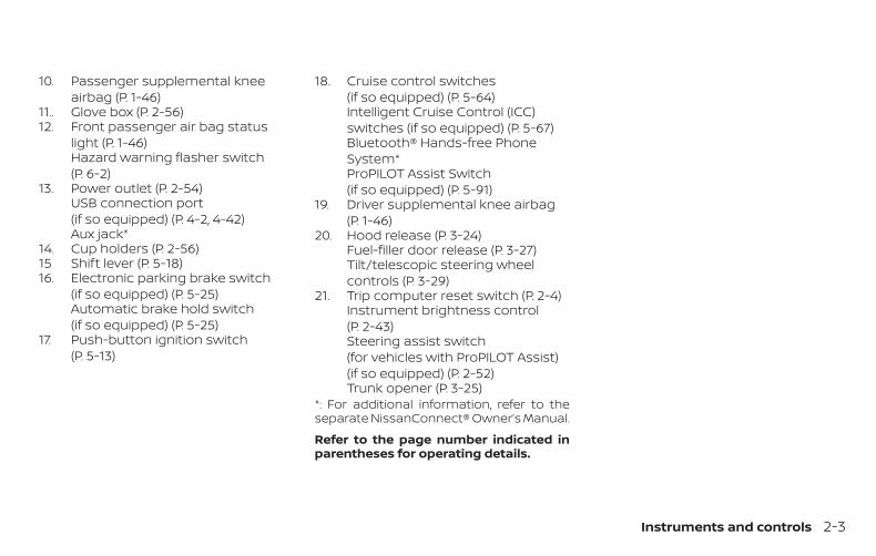
10. Passenger supplemental kneeairbag (P. 1-46)
11.. Glove box (P. 2-56)12. Front passenger air bag status
light (P. 1-46)Hazard warning flasher switch(P. 6-2)
13. Power outlet (P. 2-54)USB connection port(if so equipped) (P. 4-2, 4-42)Aux jack*
14. Cup holders (P. 2-56)15 Shift lever (P. 5-18)16. Electronic parking brake switch
(if so equipped) (P. 5-25)Automatic brake hold switch(if so equipped) (P. 5-25)
17. Push-button ignition switch(P. 5-13)
18. Cruise control switches(if so equipped) (P. 5-64)Intelligent Cruise Control (ICC)switches (if so equipped) (P. 5-67)Bluetooth® Hands-free PhoneSystem*ProPILOT Assist Switch(if so equipped) (P. 5-91)
19. Driver supplemental knee airbag(P. 1-46)
20. Hood release (P. 3-24)Fuel-filler door release (P. 3-27)Tilt/telescopic steering wheelcontrols (P. 3-29)
21. Trip computer reset switch (P. 2-4)Instrument brightness control(P. 2-43)Steering assist switch(for vehicles with ProPILOT Assist)(if so equipped) (P. 2-52)Trunk opener (P. 3-25)
*: For additional information, refer to theseparate NissanConnect® Owner’s Manual.
Refer to the page number indicated inparentheses for operating details.
Instruments and controls 2-3
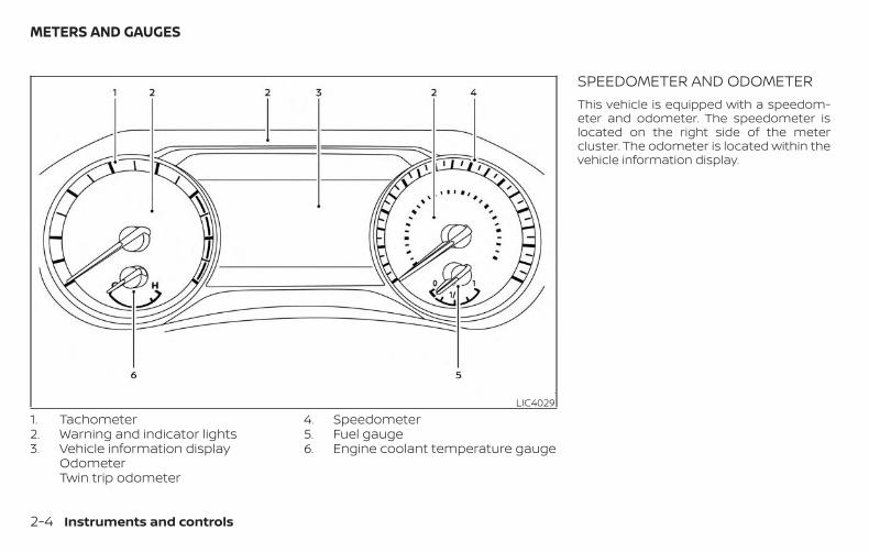
1. Tachometer2. Warning and indicator lights3. Vehicle information display
OdometerTwin trip odometer
4. Speedometer5. Fuel gauge6. Engine coolant temperature gauge
SPEEDOMETER AND ODOMETERThis vehicle is equipped with a speedom-eter and odometer. The speedometer islocated on the right side of the metercluster. The odometer is located within thevehicle information display.
LIC4029
METERS AND GAUGES
2-4 Instruments and controls
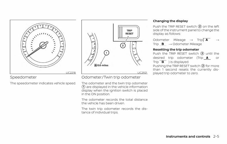
SpeedometerThe speedometer indicates vehicle speed.
Odometer/Twin trip odometerThe odometer and the twin trip odometer�1 are displayed in the vehicle informationdisplay when the ignition switch is placedin the ON position.
The odometer records the total distancethe vehicle has been driven.
The twin trip odometer records the dis-tance of individual trips.
Changing the display
Push the TRIP RESET switch �2 on the leftside of the instrument panel to change thedisplay as follows:
Odometer Mileage → Trip →Trip → Odometer Mileage
Resetting the trip odometerPush the TRIP RESET switch �2 until thedesired trip odometer (Trip orTrip ) is displayed.Pushing the TRIP RESET switch �2 for morethan 1 second resets the currently dis-played trip odometer to zero.LIC2218 LIC2921
Instruments and controls 2-5
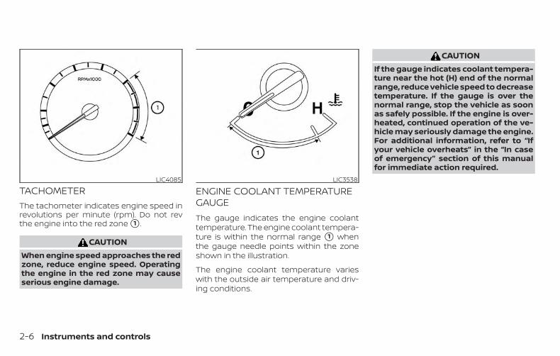
TACHOMETERThe tachometer indicates engine speed inrevolutions per minute (rpm). Do not revthe engine into the red zone �1 .
CAUTIONWhen engine speed approaches the redzone, reduce engine speed. Operatingthe engine in the red zone may causeserious engine damage.
ENGINE COOLANT TEMPERATUREGAUGEThe gauge indicates the engine coolanttemperature. The engine coolant tempera-ture is within the normal range �1 whenthe gauge needle points within the zoneshown in the illustration.
The engine coolant temperature varieswith the outside air temperature and driv-ing conditions.
CAUTIONIf the gauge indicates coolant tempera-ture near the hot (H) end of the normalrange, reduce vehicle speed to decreasetemperature. If the gauge is over thenormal range, stop the vehicle as soonas safely possible. If the engine is over-heated, continued operation of the ve-hicle may seriously damage the engine.For additional information, refer to “Ifyour vehicle overheats” in the “In caseof emergency” section of this manualfor immediate action required.
LIC4085 LIC3538
2-6 Instruments and controls
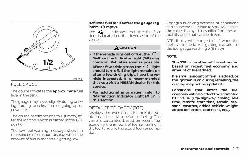
FUEL GAUGEThe gauge indicates the approximate fuellevel in the tank.
The gauge may move slightly during brak-ing, turning, acceleration, or going up ordown hills.
The gauge needle returns to 0 (Empty) af-ter the ignition switch is placed in the OFFposition.
The low fuel warning message shows inthe vehicle information display when theamount of fuel in the tank is getting low.
Refill the fuel tank before the gauge reg-isters 0 (Empty).The indicates that the fuel-fillerdoor is located on the driver’s side of thevehicle.
CAUTION
∙ If the vehicle runs out of fuel, theMalfunction Indicator Light (MIL) maycome on. Refuel as soon as possible.After a few driving trips, the lightshould turn off. If the light remains onafter a few driving trips, have the ve-hicle inspected. It is recommendedthat you visit a NISSAN dealer for thisservice.
∙ For additional information, refer to“Malfunction Indicator Light (MIL)” inthis section.
DISTANCE TO EMPTY (DTE)Displays the estimated distance the ve-hicle can be driven before refueling. Thevalue is calculated based on recent fueleconomy, the amount of fuel remaining inthe fuel tank, and the actual fuel consump-tion.
Changes in driving patterns or conditionscan cause the DTE value to vary. As a result,the value displayed may differ from the ac-tual distance that can be driven.
DTE display will change to “---” when thefuel level in the tank is getting low, prior tothe fuel gauge reaching 0 (Empty).
NOTE:
∙ The DTE value after refill is estimatedbased on recent fuel economy andamount of fuel added.
∙ If a small amount of fuel is added, orthe ignition is on during refueling, thedisplay may not be updated.
∙ Conditions that affect the fueleconomy will also affect the estimatedDTE value (city/highway driving, idletime, remote start time, terrain, sea-sonal weather, added vehicle weight,added deflectors, roof racks, etc.).
LIC2222
Instruments and controls 2-7
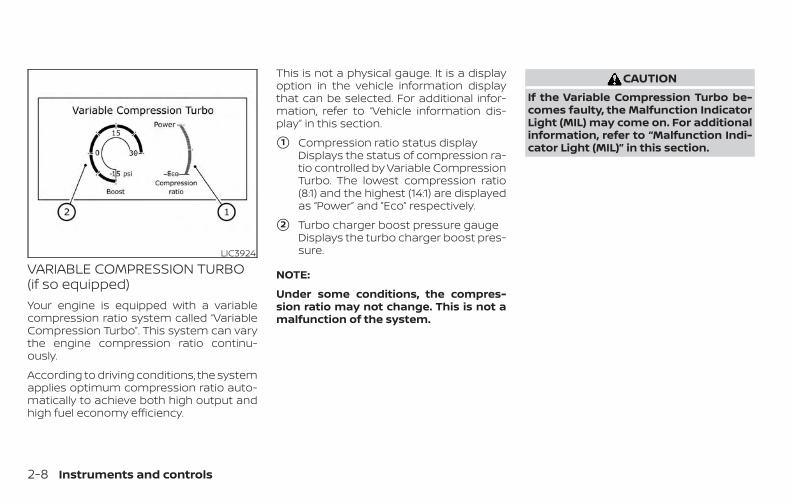
VARIABLE COMPRESSION TURBO(if so equipped)Your engine is equipped with a variablecompression ratio system called “VariableCompression Turbo”. This system can varythe engine compression ratio continu-ously.
According to driving conditions, the systemapplies optimum compression ratio auto-matically to achieve both high output andhigh fuel economy efficiency.
This is not a physical gauge. It is a displayoption in the vehicle information displaythat can be selected. For additional infor-mation, refer to “Vehicle information dis-play” in this section.
�1 Compression ratio status displayDisplays the status of compression ra-tio controlled by Variable CompressionTurbo. The lowest compression ratio(8:1) and the highest (14:1) are displayedas “Power” and ”Eco” respectively.
�2 Turbo charger boost pressure gaugeDisplays the turbo charger boost pres-sure.
NOTE:
Under some conditions, the compres-sion ratio may not change. This is not amalfunction of the system.
CAUTIONIf the Variable Compression Turbo be-comes faulty, the Malfunction IndicatorLight (MIL) may come on. For additionalinformation, refer to “Malfunction Indi-cator Light (MIL)” in this section.
LIC3924
2-8 Instruments and controls
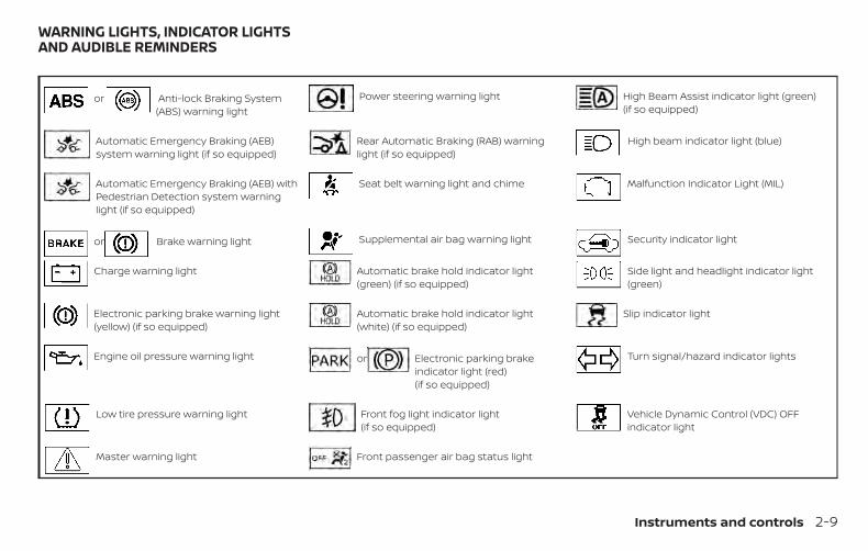
or Anti-lock Braking System(ABS) warning light
Power steering warning light High Beam Assist indicator light (green)(if so equipped)
Automatic Emergency Braking (AEB)system warning light (if so equipped)
Rear Automatic Braking (RAB) warninglight (if so equipped)
High beam indicator light (blue)
Automatic Emergency Braking (AEB) withPedestrian Detection system warninglight (if so equipped)
Seat belt warning light and chime Malfunction Indicator Light (MIL)
or Brake warning light Supplemental air bag warning light Security indicator light
Charge warning light Automatic brake hold indicator light(green) (if so equipped)
Side light and headlight indicator light(green)
Electronic parking brake warning light(yellow) (if so equipped)
Automatic brake hold indicator light(white) (if so equipped)
Slip indicator light
Engine oil pressure warning light or Electronic parking brakeindicator light (red)(if so equipped)
Turn signal/hazard indicator lights
Low tire pressure warning light Front fog light indicator light(if so equipped)
Vehicle Dynamic Control (VDC) OFFindicator light
Master warning light Front passenger air bag status light
WARNING LIGHTS, INDICATOR LIGHTSAND AUDIBLE REMINDERS
Instruments and controls 2-9
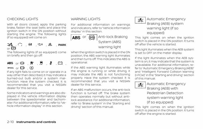
CHECKING LIGHTSWith all doors closed, apply the parkingbrake, fasten the seat belts and place theignition switch in the ON position withoutstarting the engine. The following lights(if so equipped) will come on:
, , , , , PARKorThe following lights (if so equipped) comeon briefly and then go off:
or , , , , ,
or ,If any light fails to come on or operate in away other than described, it may indicate aburned-out bulb and/or a system mal-function. Have the system checked. It isrecommended that you visit a NISSANdealer for this service.
Some indicators and warnings are also dis-played in the vehicle information displaybetween the speedometer and tachom-eter. For additional information, refer to “Ve-hicle information display” in this section.
WARNING LIGHTSFor additional information on warningsand indicators, refer to “Vehicle informationdisplay” in this section.
or Anti-lock BrakingSystem (ABS)warning light
When the ignition switch is placed in the ONposition, the ABS warning light illuminatesand then turns off. This indicates the ABS isoperational.
If the ABS warning light illuminates whilethe engine is running or while driving, itmay indicate the ABS is not functioningproperly. Have the system checked. It isrecommended that you visit a NISSANdealer for this service.
If an ABS malfunction occurs, the anti-lockfunction is turned off. The brake systemthen operates normally but without anti-lock assistance. For additional information,refer to “Brake system” in the “Starting anddriving” section of this manual.
Automatic EmergencyBraking (AEB) systemwarning light (if soequipped)
This light comes on when the ignitionswitch is placed in the ON position. It turnsoff after the vehicle is started.
This light illuminates when the AEB systemis set to OFF on the meter display.
If the light illuminates when the AEB sys-tem is on, it may indicate that the system isunavailable. For additional information, re-fer to “Automatic Emergency Braking (AEB)”and “Intelligent Forward Collision Warning(I-FCW)” in the “Starting and driving” sectionof this manual.
Automatic EmergencyBraking (AEB) withPedestrian Detectionsystem warning light(if so equipped)
This light comes on when the ignitionswitch is placed in the ON position. It turnsoff after the engine is started.
2-10 Instruments and controls
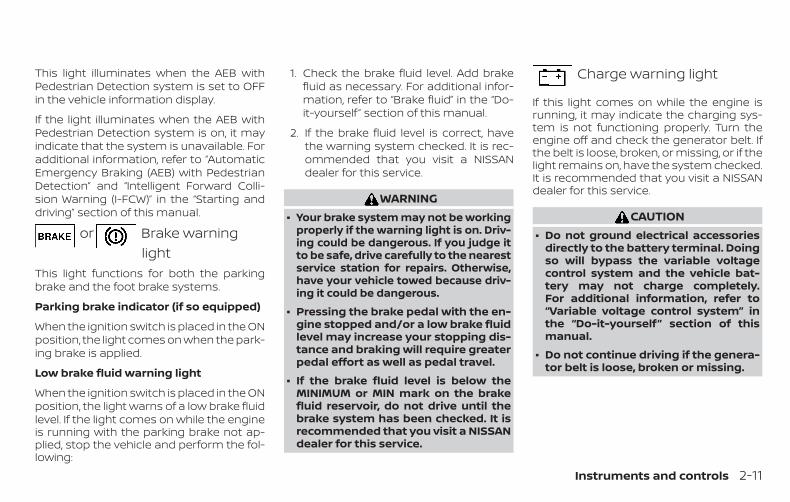
This light illuminates when the AEB withPedestrian Detection system is set to OFFin the vehicle information display.
If the light illuminates when the AEB withPedestrian Detection system is on, it mayindicate that the system is unavailable. Foradditional information, refer to “AutomaticEmergency Braking (AEB) with PedestrianDetection” and “Intelligent Forward Colli-sion Warning (I-FCW)” in the “Starting anddriving” section of this manual.
or Brake warninglight
This light functions for both the parkingbrake and the foot brake systems.
Parking brake indicator (if so equipped)
When the ignition switch is placed in the ONposition, the light comes on when the park-ing brake is applied.
Low brake fluid warning light
When the ignition switch is placed in the ONposition, the light warns of a low brake fluidlevel. If the light comes on while the engineis running with the parking brake not ap-plied, stop the vehicle and perform the fol-lowing:
1. Check the brake fluid level. Add brakefluid as necessary. For additional infor-mation, refer to “Brake fluid” in the “Do-it-yourself ” section of this manual.
2. If the brake fluid level is correct, havethe warning system checked. It is rec-ommended that you visit a NISSANdealer for this service.
WARNING∙ Your brake system may not be working
properly if the warning light is on. Driv-ing could be dangerous. If you judge itto be safe, drive carefully to the nearestservice station for repairs. Otherwise,have your vehicle towed because driv-ing it could be dangerous.
∙ Pressing the brake pedal with the en-gine stopped and/or a low brake fluidlevel may increase your stopping dis-tance and braking will require greaterpedal effort as well as pedal travel.
∙ If the brake fluid level is below theMINIMUM or MIN mark on the brakefluid reservoir, do not drive until thebrake system has been checked. It isrecommended that you visit a NISSANdealer for this service.
Charge warning light
If this light comes on while the engine isrunning, it may indicate the charging sys-tem is not functioning properly. Turn theengine off and check the generator belt. Ifthe belt is loose, broken, or missing, or if thelight remains on, have the system checked.It is recommended that you visit a NISSANdealer for this service.
CAUTION∙ Do not ground electrical accessories
directly to the battery terminal. Doingso will bypass the variable voltagecontrol system and the vehicle bat-tery may not charge completely.For additional information, refer to“Variable voltage control system” inthe “Do-it-yourself” section of thismanual.
∙ Do not continue driving if the genera-tor belt is loose, broken or missing.
Instruments and controls 2-11
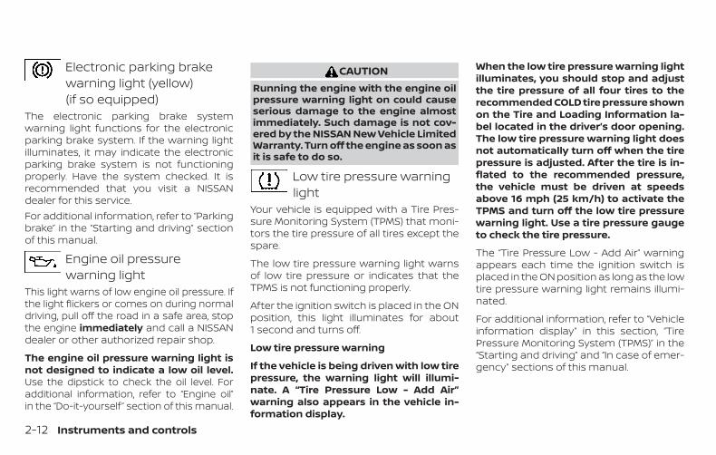
Electronic parking brakewarning light (yellow)(if so equipped)
The electronic parking brake systemwarning light functions for the electronicparking brake system. If the warning lightilluminates, it may indicate the electronicparking brake system is not functioningproperly. Have the system checked. It isrecommended that you visit a NISSANdealer for this service.For additional information, refer to “Parkingbrake” in the “Starting and driving” sectionof this manual.
Engine oil pressurewarning light
This light warns of low engine oil pressure. Ifthe light flickers or comes on during normaldriving, pull off the road in a safe area, stopthe engine immediately and call a NISSANdealer or other authorized repair shop.
The engine oil pressure warning light isnot designed to indicate a low oil level.Use the dipstick to check the oil level. Foradditional information, refer to “Engine oil”in the “Do-it-yourself ” section of this manual.
CAUTIONRunning the engine with the engine oilpressure warning light on could causeserious damage to the engine almostimmediately. Such damage is not cov-ered by the NISSAN New Vehicle LimitedWarranty. Turn off the engine as soon asit is safe to do so.
Low tire pressure warninglight
Your vehicle is equipped with a Tire Pres-sure Monitoring System (TPMS) that moni-tors the tire pressure of all tires except thespare.
The low tire pressure warning light warnsof low tire pressure or indicates that theTPMS is not functioning properly.
After the ignition switch is placed in the ONposition, this light illuminates for about1 second and turns off.
Low tire pressure warning
If the vehicle is being driven with low tirepressure, the warning light will illumi-nate. A “Tire Pressure Low - Add Air”warning also appears in the vehicle in-formation display.
When the low tire pressure warning lightilluminates, you should stop and adjustthe tire pressure of all four tires to therecommended COLD tire pressure shownon the Tire and Loading Information la-bel located in the driver’s door opening.The low tire pressure warning light doesnot automatically turn off when the tirepressure is adjusted. After the tire is in-flated to the recommended pressure,the vehicle must be driven at speedsabove 16 mph (25 km/h) to activate theTPMS and turn off the low tire pressurewarning light. Use a tire pressure gaugeto check the tire pressure.
The “Tire Pressure Low - Add Air” warningappears each time the ignition switch isplaced in the ON position as long as the lowtire pressure warning light remains illumi-nated.
For additional information, refer to “Vehicleinformation display” in this section, “TirePressure Monitoring System (TPMS)” in the“Starting and driving” and “In case of emer-gency” sections of this manual.
2-12 Instruments and controls
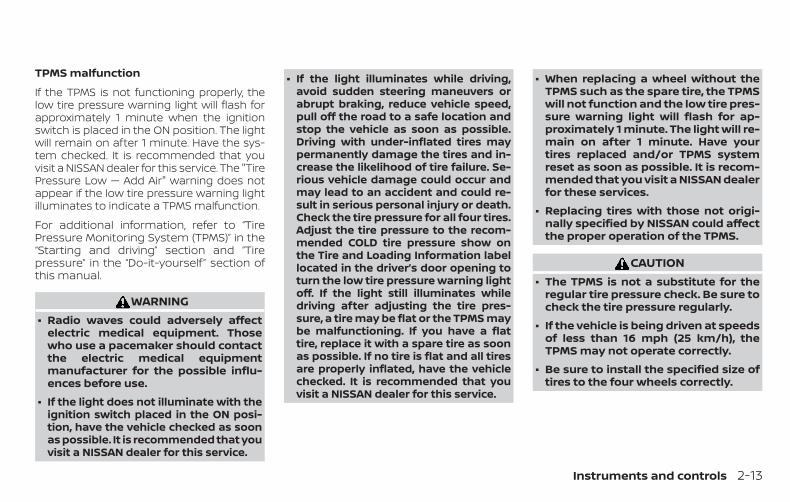
TPMS malfunction
If the TPMS is not functioning properly, thelow tire pressure warning light will flash forapproximately 1 minute when the ignitionswitch is placed in the ON position. The lightwill remain on after 1 minute. Have the sys-tem checked. It is recommended that youvisit a NISSAN dealer for this service. The "TirePressure Low — Add Air" warning does notappear if the low tire pressure warning lightilluminates to indicate a TPMS malfunction.
For additional information, refer to “TirePressure Monitoring System (TPMS)” in the“Starting and driving” section and “Tirepressure” in the “Do-it-yourself ” section ofthis manual.
WARNING∙ Radio waves could adversely affect
electric medical equipment. Thosewho use a pacemaker should contactthe electric medical equipmentmanufacturer for the possible influ-ences before use.
∙ If the light does not illuminate with theignition switch placed in the ON posi-tion, have the vehicle checked as soonas possible. It is recommended that youvisit a NISSAN dealer for this service.
∙ If the light illuminates while driving,avoid sudden steering maneuvers orabrupt braking, reduce vehicle speed,pull off the road to a safe location andstop the vehicle as soon as possible.Driving with under-inflated tires maypermanently damage the tires and in-crease the likelihood of tire failure. Se-rious vehicle damage could occur andmay lead to an accident and could re-sult in serious personal injury or death.Check the tire pressure for all four tires.Adjust the tire pressure to the recom-mended COLD tire pressure show onthe Tire and Loading Information labellocated in the driver’s door opening toturn the low tire pressure warning lightoff. If the light still illuminates whiledriving after adjusting the tire pres-sure, a tire may be flat or the TPMS maybe malfunctioning. If you have a flattire, replace it with a spare tire as soonas possible. If no tire is flat and all tiresare properly inflated, have the vehiclechecked. It is recommended that youvisit a NISSAN dealer for this service.
∙ When replacing a wheel without theTPMS such as the spare tire, the TPMSwill not function and the low tire pres-sure warning light will flash for ap-proximately 1 minute. The light will re-main on after 1 minute. Have yourtires replaced and/or TPMS systemreset as soon as possible. It is recom-mended that you visit a NISSAN dealerfor these services.
∙ Replacing tires with those not origi-nally specified by NISSAN could affectthe proper operation of the TPMS.
CAUTION∙ The TPMS is not a substitute for the
regular tire pressure check. Be sure tocheck the tire pressure regularly.
∙ If the vehicle is being driven at speedsof less than 16 mph (25 km/h), theTPMS may not operate correctly.
∙ Be sure to install the specified size oftires to the four wheels correctly.
Instruments and controls 2-13
Master warning light
When the ignition is in the ON position, themaster warning light illuminates if any ofthe following are displayed on the vehicleinformation display.
∙ No key warning
∙ Low windshield-washer fluid warning
∙ Parking brake release warning
∙ Door/trunk open warning
∙ Loose fuel cap
∙ Low tire pressure warning
Power steering warninglight
WARNING∙ If the engine is not running or is
turned off while driving, the power as-sist for the steering will not work.Steering will be harder to operate.
∙ When the power steering warninglight illuminates with the engine run-ning, there will be no power assist forthe steering. You will still have controlof the vehicle, but the steering will beharder to operate. Have the powersteering system checked. It is recom-mended that you visit a NISSAN dealerfor this service.
When the ignition switch is placed in the ONposition, the power steering warning lightilluminates. After starting the engine, thepower steering warning light turns off. Thisindicates the power steering is operational.
If the power steering warning light illumi-nates while the engine is running, it mayindicate the power steering is not function-ing properly and may need servicing. Havethe power steering checked. It is recom-mended that you visit a NISSAN dealer forthis service.
When the power steering warning light illu-minates with the engine running, there willbe no power assist for the steering, but youwill still have control of the vehicle. At thistime, greater steering effort is required tooperate the steering wheel, especially insharp turns and at low speeds.
For additional information, refer to “Powersteering” in the “Starting and driving” sec-tion of this manual.
Rear Automatic Braking(RAB) warning light (if soequipped)
This light comes on when the ignitionswitch is placed in the ON position. It turnsoff after the engine is started.
This light illuminates when the RAB systemis turned off in the vehicle information dis-play.
If the light illuminates when the RAB sys-tem is on, it may indicate that the system isunavailable. For additional information, re-fer to “Rear Automatic Braking (RAB)” in the“Starting and driving” section of thismanual.
Seat belt warning light andchime
The light and chime remind you to fastenthe driver and front passenger seat belts.
For additional information, refer to “Seatbelts” in the “Safety—Seats, seat belts andsupplemental restraint system” section ofthis manual.
2-14 Instruments and controls
Supplemental air bagwarning light
When the ignition switch is placed in the ONor START position, the supplemental airbag warning light illuminates for about7 seconds and then turns off. This meansthe system is operational.
If any of the following conditions occur, thefront air bag, side air bag, curtain air bag,and pretensioner systems need servicingand your vehicle must be taken to a NISSANdealer:
∙ The supplemental air bag warning lightremains on after approximately 7 sec-onds.
∙ The supplemental air bag warning lightflashes intermittently.
∙ The supplemental air bag warning lightdoes not come on at all.
Unless checked and repaired, the supple-mental restraint system (air bag system)and/or the pretensioners may not functionproperly. For additional details, refer to“Supplemental Restraint System (SRS)” inthe “Safety—Seats, seat belts and supple-mental restraint system” section of thismanual.
WARNINGIf the supplemental air bag warninglight is on, it could mean that the frontair bag, side air bag, curtain air bag sys-tems and/or pretensioner systems willnot operate in an accident. To helpavoid injury to yourself or others, haveyour vehicle checked as soon as pos-sible. It is recommended that you visit aNISSAN dealer for this service.
INDICATOR LIGHTSFor additional information, refer to “Vehicleinformation display” in this section.
Automatic brake holdindicator light (green) (if soequipped)
The automatic brake hold indicator light(green) illuminates while the automaticbrake hold system is operating.
For additional information, refer to “Auto-matic brake hold” in the “Starting and driv-ing” section of the Owner’s Manual.
Automatic brake holdindicator light (white)(if so equipped)
The automatic brake hold indicator (white)illuminates when the automatic brake holdsystem is on standby.
For additional information, refer to “Auto-matic brake hold” in the “Starting and driv-ing” section of the Owner’s Manual.
or Electronic parkingbrake indicatorlight (red) (if soequipped)
This light illuminates when the electronicparking brake system is operating.
When the ignition switch is placed in the ONposition, the electronic parking brakewarning light illuminates. When the engineis started and the parking brake is released,the warning light turns off.
If the parking brake is not released, theelectronic parking brake warning light re-mains illuminated. Ensure the electronicparking brake warning light has turned offbefore driving.
Instruments and controls 2-15
If the electronic parking brake warning lightilluminates or flashes while the electronicparking brake system warning light(yellow) illuminates, it may indicate that theelectronic parking brake system is notfunctioning properly. Have the systemchecked. It is recommended that you visit aNISSAN dealer for this service.For additional information, refer to “Parkingbrake” in the “Starting and driving” sectionof this manual.
Front fog light indicatorlight (if so equipped)
The front fog light indicator light illumi-nates when the front fog lights are on. Foradditional information, refer to “Fog lightswitch” in this section.
Front passenger air bagstatus light
The front passenger air bag status light willbe lit and the passenger front air bag will beoff depending on how the front passengerseat is being used.
For additional information, refer to “Frontpassenger air bag and status light” in the“Safety — Seats, seat belts and supplemen-tal restraint system” section of this manual.
High Beam Assist indicatorlight (green) (if so equipped)
This indicator light illuminates when theheadlights come on while the headlightswitch is in the AUTO position with the highbeams selected. This indicates that thehigh beam assist is operational.
For additional information, refer to “Head-light and turn signal switch” in this section.
High beam indicator light(blue)
This blue light comes on when the head-light high beams are on and goes out whenthe low beams are selected.
The high beam indicator light also comeson when the passing signal is activated.
Malfunction Indicator Light(MIL)
If this indicator light comes on steady orblinks while the engine is running, it mayindicate a potential emission control mal-function.
The MIL may also come on steady if thefuel-filler cap is loose or missing, or if thevehicle runs out of fuel. Check to make surethe fuel-filler cap is installed and closedtightly, and that the vehicle has at least3 gallons (11.4 liters) of fuel in the fuel tank.
After a few driving trips, the lightshould turn off if no other potential emis-sion control system malfunction exists.If this indicator light comes on steady for20 seconds and then blinks for 10 secondswhen the engine is not running, it indicatesthat the vehicle is not ready for an emissioncontrol system inspection/maintenancetest. For additional information, refer to“Readiness for Inspection/Maintenance(I/M) test” in the “Technical and consumerinformation” section of this manual.
2-16 Instruments and controls
Operation
The MIL will come on in one of two ways:
∙ MIL on steady — An emission controlsystem malfunction has been de-tected. Check the fuel-filler cap if theLoose Fuel Cap warning appears in thevehicle information display. If the fuel-filler cap is loose or missing, tighten orinstall the cap and continue to drive thevehicle. The light should turn offafter a few driving trips. If the lightdoes not turn off after a few drivingtrips, have the vehicle inspected. It isrecommended that you visit a NISSANdealer for this service. You do not needto have your vehicle towed to thedealer.
∙ MIL blinking — An engine misfire has beendetected which may damage the emis-sion control system. To reduce or avoidemission control system damage:
– do not drive at speeds above45 mph (72 km/h).
– avoid hard acceleration or decelera-tion.
– avoid steep uphill grades.
– if possible, reduce the amount ofcargo being hauled or towed.
The MIL may stop blinking and come onsteady. Have the vehicle inspected. It is rec-ommended that you visit a NISSAN dealerfor this service. You do not need to haveyour vehicle towed to the dealer.
CAUTIONContinued vehicle operation withouthaving the emission control systemchecked and repaired as necessarycould lead to poor driveability, reducedfuel economy, and possible damage tothe emission control system.
Security indicator light
This light blinks when the ignition switch isplaced in the OFF, LOCK or AUTO ACC posi-tion.
The blinking security indicator light indi-cates that the security systems equippedon the vehicle are operational.
For additional information, refer to “Securitysystems” in this section.
Side light and headlightindicator light (green)
The side light and headlight indicator lightilluminates when the side light or headlightposition is selected. For additional informa-tion, refer to “Headlight and turn signalswitch” in this section.
Slip indicator light
This indicator light will blink when the Ve-hicle Dynamic Control (VDC) system is op-erating, thus alerting the driver to the factthat the road surface is slippery and thevehicle is nearing its traction limits.
You may feel or hear the system working;this is normal.
The light will blink for a few seconds afterthe VDC system stops limiting wheel spin.
The indicator light also comes onwhen you place the ignition switch in theON position. The light will turn off after ap-proximately 2 seconds if the system is op-erational. If the light does not come onhave the system checked. It is recom-mended that you visit a NISSAN dealer forthis service.
Instruments and controls 2-17
Turn signal/hazardindicator lights
The appropriate light flashes when the turnsignal switch is activated.
Both lights flash when the hazard switch isturned on.
Vehicle Dynamic Control(VDC) OFF indicator light
This indicator light comes on when theVDC is turned off in the vehicle informationdisplay. This indicates the VDC has beenturned off.
Turn the VDC on using the vehicle informa-tion display, or by restarting the engine. Foradditional information, refer to “Vehicle Dy-namic Control (VDC) system” in the “Start-ing and driving” section of this manual.
The VDC light also comes on when the igni-tion switch is placed in the ON position. Thelight will turn off after a period of time if thesystem is operational. If the light stays on orcomes on along with the indicator lightwhile you are driving, have the VDC systemchecked. It is recommended that you visit aNISSAN dealer for this service.
WARNINGVDC should remain on unless freeing avehicle from mud or snow.
While the VDC system is operating, youmight feel a slight vibration or hear the sys-tem working when starting the vehicle oraccelerating, but this is normal.
AUDIBLE REMINDERSBrake pad wear warningThe disc brake pads have audible wearwarnings. When a disc brake pad requiresreplacement, it makes a high pitchedscraping sound when the vehicle is in mo-tion, whether or not the brake pedal is de-pressed. Have the brakes checked as soonas possible if the warning sound is heard.
Light reminder chimeWith the ignition switch placed in the OFFposition, a chime sounds when the driver’sdoor is opened if the headlights or parkinglights are on.
Turn the headlight control switch off beforeleaving the vehicle.
NISSAN Intelligent Key® doorbuzzerThe Intelligent Key door buzzer sounds ifthe Intelligent Key is left inside the vehiclewhen locking the doors. When the buzzersounds, be sure to check both the vehicleand the Intelligent Key. For additional infor-mation, refer to “NISSAN Intelligent Key®” inthe “Pre-driving checks and adjustments”section of this manual.
2-18 Instruments and controls
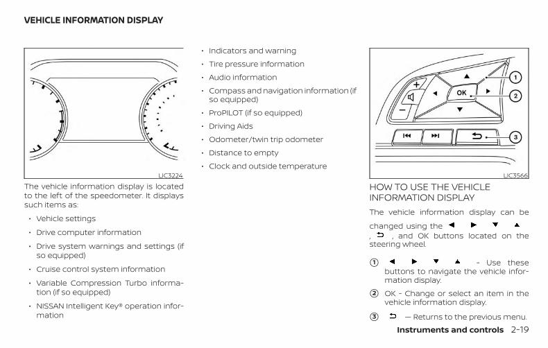
The vehicle information display is locatedto the left of the speedometer. It displayssuch items as:
∙ Vehicle settings
∙ Drive computer information
∙ Drive system warnings and settings (ifso equipped)
∙ Cruise control system information
∙ Variable Compression Turbo informa-tion (if so equipped)
∙ NISSAN Intelligent Key® operation infor-mation
∙ Indicators and warning
∙ Tire pressure information
∙ Audio information
∙ Compass and navigation information (ifso equipped)
∙ ProPILOT (if so equipped)
∙ Driving Aids
∙ Odometer/twin trip odometer
∙ Distance to empty
∙ Clock and outside temperature
HOW TO USE THE VEHICLEINFORMATION DISPLAYThe vehicle information display can be
changed using the, , and OK buttons located on thesteering wheel.
�1 - Use thesebuttons to navigate the vehicle infor-mation display.
�2 OK - Change or select an item in thevehicle information display.
�3 — Returns to the previous menu.
LIC3224 LIC3566
VEHICLE INFORMATION DISPLAY
Instruments and controls 2-19
The OK, and buttons alsocontrol audio and control panel functionsin some conditions. Most screens andmenus offer instruction prompts of thesteering switch buttons to indicate how tocontrol the vehicle information display.Dots on the right side of the vehicle infor-mation display will appear if there is morethan one page of menu items or warningmessages. The OK button changes theaudio source and the buttonsalso control voice recognition manualmode. The OK button can be used tochange the audio source when the audioscreen is displayed. The but-tons can be used when controlling voicerecognition prompts manually. For addi-tional information, refer to the separateNissanConnect® Owner’s Manual.
STARTUP DISPLAYWhen the vehicle in placed in the ON positionthe vehicle information display may displaythe following screens (if so equipped):
∙ Home
∙ Drive Computer — Speed, FuelEconomy, Trip Distance & Time
∙ Convenience
∙ Digital speed and average speed
∙ Instant fuel economy/ average fueleconomy
∙ Traffic Sign Recognition
∙ Tire Pressure
∙ Variable Compression Turbo
∙ Speed Limit Sign
∙ Compass and Navigation
∙ Audio/telephone
∙ Intelligent Cruise Control (ICC)
∙ ProPILOT
∙ Driving Aids
∙ Settings
∙ Warnings*
*Warnings will only display if there are anypresent. For additional information, refer to“Vehicle information display warnings andindicators” in this section.
To control what items display in the vehicleinformation display, refer to “How to use thevehicle information display” in this section.
RESETTING THE DRIVE COMPUTERThe drive computer is divided across threescreens:
∙ Average Speed
∙ Average Fuel Economy
∙ Trip Distance & Time
1. Press the but-tons until you reach the desired drivecomputer mode.
2. Press and hold the OK button for ap-proximately 1 second to reset the infor-mation on the currently displayedscreen.
NOTE:
If you wish to reset all drive computervalues at once, press and hold the OKbutton for approximately 3 seconds untila reset menu appears; and follow theinstructions.
2-20 Instruments and controls
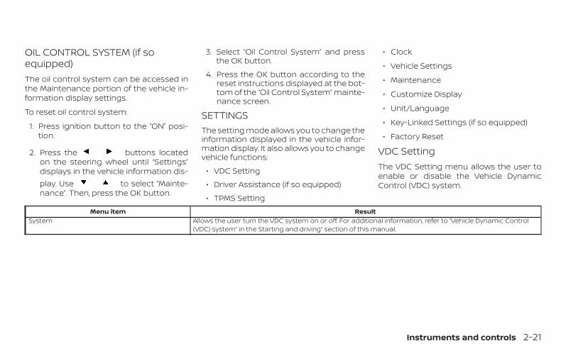
OIL CONTROL SYSTEM (if soequipped)The oil control system can be accessed inthe Maintenance portion of the vehicle in-formation display settings.
To reset oil control system:
1. Press ignition button to the “ON” posi-tion.
2. Press the buttons locatedon the steering wheel until “Settings”displays in the vehicle information dis-play. Use to select “Mainte-nance”. Then, press the OK button.
3. Select “Oil Control System” and pressthe OK button.
4. Press the OK button according to thereset instructions displayed at the bot-tom of the “Oil Control System” mainte-nance screen.
SETTINGSThe setting mode allows you to change theinformation displayed in the vehicle infor-mation display. It also allows you to changevehicle functions:
∙ VDC Setting
∙ Driver Assistance (if so equipped)
∙ TPMS Setting
∙ Clock
∙ Vehicle Settings
∙ Maintenance
∙ Customize Display
∙ Unit/Language
∙ Key-Linked Settings (if so equipped)
∙ Factory Reset
VDC SettingThe VDC Setting menu allows the user toenable or disable the Vehicle DynamicControl (VDC) system.
Menu item ResultSystem Allows the user turn the VDC system on or off. For additional information, refer to “Vehicle Dynamic Control
(VDC) system” in the Starting and driving” section of this manual.
Instruments and controls 2-21
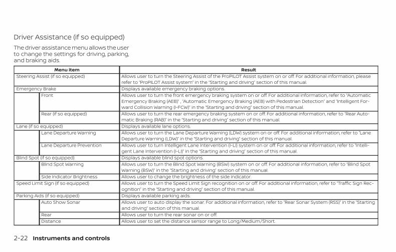
Driver Assistance (if so equipped)The driver assistance menu allows the userto change the settings for driving, parking,and braking aids.
Menu item ResultSteering Assist (if so equipped) Allows user to turn the Steering Assist of the ProPILOT Assist system on or off. For additional information, please
refer to “ProPILOT Assist system” in the “Starting and driving” section of this manual.Emergency Brake Displays available emergency braking options.
Front Allows user to turn the front emergency braking system on or off. For additional information, refer to “AutomaticEmergency Braking (AEB)” , “Automatic Emergency Braking (AEB) with Pedestrian Detection” and “Intelligent For-ward Collision Warning (I-FCW)” in the “Starting and driving” section of this manual.
Rear (if so equipped) Allows user to turn the rear emergency braking system on or off. For additional information, refer to “Rear Auto-matic Braking (RAB)” in the “Starting and driving” section of this manual.
Lane (if so equipped) Displays available lane options.Lane Departure Warning Allows user to turn the Lane Departure Warning (LDW) system on or off. For additional information, refer to “Lane
Departure Warning (LDW)” in the “Starting and driving” section of this manual.Lane Departure Prevention Allows user to turn Intelligent Lane Intervention (I-LI) system on or off. For additional information, refer to “Intelli-
gent Lane Intervention (I-LI)” in the “Starting and driving” section of this manual.Blind Spot (if so equipped) Displays available blind spot options.
Blind Spot Warning Allows user to turn the Blind Spot Warning (BSW) system on or off. For additional information, refer to “Blind SpotWarning (BSW)” in the “Starting and driving” section of this manual.
Side Indicator Brightness Allows user to change the brightness of the side indicator.Speed Limit Sign (if so equipped) Allows user to turn the Speed Limit Sign recognition on or off. For additional information, refer to “Traffic Sign Rec-
ognition” in the “Starting and driving” section of this manual.Parking Aids (if so equipped) Displays available parking aids.
Auto Show Sonar Allows user to auto display the sonar. For additional information, refer to “Rear Sonar System (RSS)” in the “Startingand driving” section of this manual.
Rear Allows user to turn the rear sonar on or off.Distance Allows user to set the distance sensor range to Long/Medium/Short.
2-22 Instruments and controls
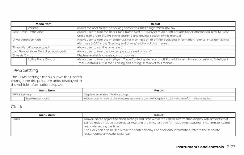
Menu item ResultVolume Allows the user to set the parking sensor volume to High/Medium/Low.
Rear Cross Traffic Alert Allows user to turn the Rear Cross Traffic Alert (RCTA) system on or off. For additional information, refer to “RearCross Traffic Alert (RCTA)” in the “Starting and driving” section of this manual.
Driver Attention Alert Allows user to turn the Intelligent Driver Alertness on or off. For additional information, refer to “Intelligent DriverAlertness (I-DA)” in the “Starting and driving” section of this manual.
Timer Alert (if so equipped) Allows user to set the timer alert.Low Temperature Alert (if so equipped) Allows user to turn the low temperature alert on or off.Chassis Control Displays available chassis control options.
Active Trace Control Allows user to turn the Intelligent Trace Control system on or off. For additional information, refer to “IntelligentTrace Control (I-TC)” in the “Starting and driving” section of this manual.
TPMS SettingThe TPMS settings menu allows the user tochange the tire pressure units displayed inthe vehicle information display.
Menu item ResultTPMS Setting Displays available TPMS settings.
Tire Pressure Unit Allows user to select the tire pressure units that will display in the vehicle information display.
Clock
Menu item ResultClock Allows user to adjust the clock settings and time within the vehicle information display. Adjustments that
can be made include automatically setting the time, 12H/24H format, Daylight Saving Time, time zone, andmanually setting the time.The clock can also be set within the center display. For additional information, refer to the separateNissanConnect® Owner’s Manual.
Instruments and controls 2-23
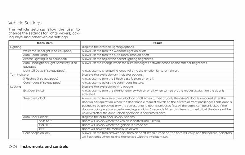
Vehicle SettingsThe vehicle settings allow the user tochange the settings for lights, wipers, lock-ing, keys, and other vehicle settings.
Menu item ResultLighting Displays the available lighting options.
Welcome Headlight (if so equipped) Allows user to turn the welcome light on or off.Auto Room Lamp Allows user to turn the auto room lamp on or off.Accent Lighting (if so equipped) Allows user to adjust the accent lighting brightness.Auto Headlight or Light Sensitivity (if soequipped)
Allows user to change when the auto headlights activate based on the exterior brightness.
Light Off Delay (if so equipped) Allows user to change the length of time the exterior lights remain on.Turn indicator Displays the available turn indicator options.
3 Flashes (if so equipped) Allows user to turn the 3 flash pass feature on or off.Continuous (if so equipped) Allows user to adjust the continuous feature.
Locking Displays the available locking options.Ext Door Switch Allows user to turn the exterior door switch on or off. When turned on, the request switch on the door is
activated.Selective Unlock Allows user to turn selective unlock on or off. When turned on, only the driver’s door is unlocked after the
door unlock operation. When the door handle request switch on the driver’s or front passenger’s side door ispushed to be unlocked, only the corresponding door is unlocked first. All the doors can be unlocked if thedoor unlock operation is performed again within 5 seconds. When this item is turned off, all the doors will beunlocked after the door unlock operation is performed once.
Auto Door Unlock Displays the auto door unlock options.Shift to P Doors will unlock when the vehicle is shifted into P (Park).IGN OFF Doors will unlock when the ignition is turned off.OFF Doors will have to be manually unlocked.
Horn beeps on lock Allows user to turn answer back horn on or off. When turned on, the horn will chirp and the hazard indicatorswill flash once when locking the vehicle with the Intelligent Key.
2-24 Instruments and controls
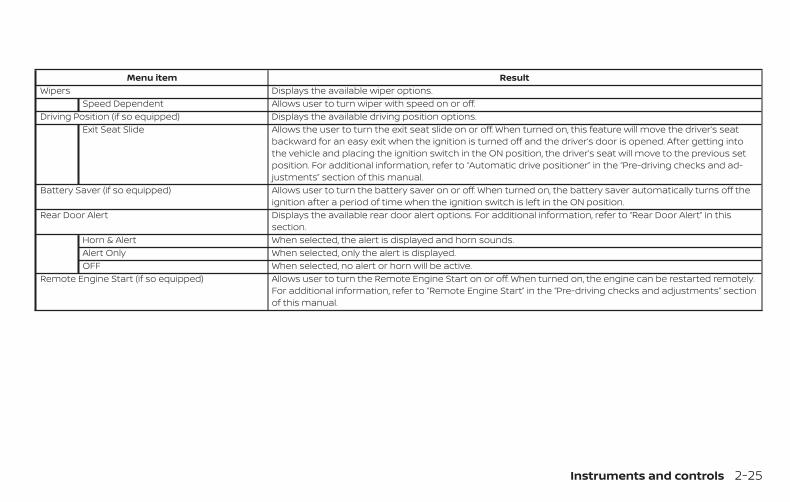
Menu item ResultWipers Displays the available wiper options.
Speed Dependent Allows user to turn wiper with speed on or off.Driving Position (if so equipped) Displays the available driving position options.
Exit Seat Slide Allows the user to turn the exit seat slide on or off. When turned on, this feature will move the driver’s seatbackward for an easy exit when the ignition is turned off and the driver’s door is opened. After getting intothe vehicle and placing the ignition switch in the ON position, the driver’s seat will move to the previous setposition. For additional information, refer to “Automatic drive positioner” in the “Pre-driving checks and ad-justments” section of this manual.
Battery Saver (if so equipped) Allows user to turn the battery saver on or off. When turned on, the battery saver automatically turns off theignition after a period of time when the ignition switch is left in the ON position.
Rear Door Alert Displays the available rear door alert options. For additional information, refer to “Rear Door Alert” in thissection.
Horn & Alert When selected, the alert is displayed and horn sounds.Alert Only When selected, only the alert is displayed.OFF When selected, no alert or horn will be active.
Remote Engine Start (if so equipped) Allows user to turn the Remote Engine Start on or off. When turned on, the engine can be restarted remotely.For additional information, refer to “Remote Engine Start” in the “Pre-driving checks and adjustments” sectionof this manual.
Instruments and controls 2-25
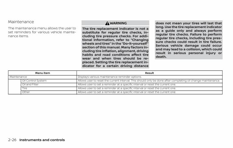
MaintenanceThe maintenance menu allows the user toset reminders for various vehicle mainte-nance items.
WARNINGThe tire replacement indicator is not asubstitute for regular tire checks, in-cluding tire pressure checks. For addi-tional information, refer to “Changingwheels and tires” in the “Do-it-yourself”section of this manual. Many factors in-cluding tire inflation, alignment, drivinghabits and road conditions affect tirewear and when tires should be re-placed. Setting the tire replacement in-dicator for a certain driving distance
does not mean your tires will last thatlong. Use the tire replacement indicatoras a guide only and always performregular tire checks. Failure to performregular tire checks, including tire pres-sure checks could result in tire failure.Serious vehicle damage could occurand may lead to a collision, which couldresult in serious personal injury ordeath.
Menu item ResultMaintenance Displays various maintenance reminder options.
Oil Control System Allows user to reset the current interval. This should only be done after completing oil change maintenance.Oil and Filter Allows user to set a reminder at a specific interval or reset the current one.Tire Allows user to set a reminder at a specific interval or reset the current one.Other Allows user to set a reminder at a specific interval or reset the current one.
2-26 Instruments and controls
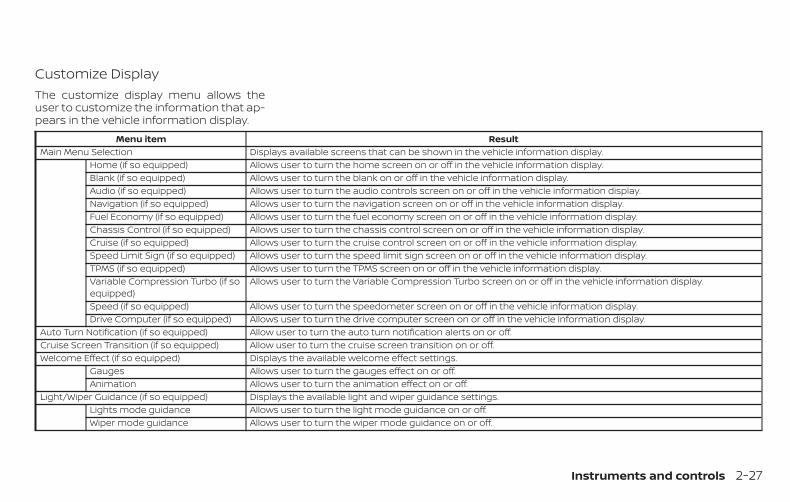
Customize DisplayThe customize display menu allows theuser to customize the information that ap-pears in the vehicle information display.
Menu item ResultMain Menu Selection Displays available screens that can be shown in the vehicle information display.
Home (if so equipped) Allows user to turn the home screen on or off in the vehicle information display.Blank (if so equipped) Allows user to turn the blank on or off in the vehicle information display.Audio (if so equipped) Allows user to turn the audio controls screen on or off in the vehicle information display.Navigation (if so equipped) Allows user to turn the navigation screen on or off in the vehicle information display.Fuel Economy (if so equipped) Allows user to turn the fuel economy screen on or off in the vehicle information display.Chassis Control (if so equipped) Allows user to turn the chassis control screen on or off in the vehicle information display.Cruise (if so equipped) Allows user to turn the cruise control screen on or off in the vehicle information display.Speed Limit Sign (if so equipped) Allows user to turn the speed limit sign screen on or off in the vehicle information display.TPMS (if so equipped) Allows user to turn the TPMS screen on or off in the vehicle information display.Variable Compression Turbo (if soequipped)
Allows user to turn the Variable Compression Turbo screen on or off in the vehicle information display.
Speed (if so equipped) Allows user to turn the speedometer screen on or off in the vehicle information display.Drive Computer (if so equipped) Allows user to turn the drive computer screen on or off in the vehicle information display.
Auto Turn Notification (if so equipped) Allow user to turn the auto turn notification alerts on or off.Cruise Screen Transition (if so equipped) Allow user to turn the cruise screen transition on or off.Welcome Effect (if so equipped) Displays the available welcome effect settings.
Gauges Allows user to turn the gauges effect on or off.Animation Allows user to turn the animation effect on or off.
Light/Wiper Guidance (if so equipped) Displays the available light and wiper guidance settings.Lights mode guidance Allows user to turn the light mode guidance on or off.Wiper mode guidance Allows user to turn the wiper mode guidance on or off.
Instruments and controls 2-27
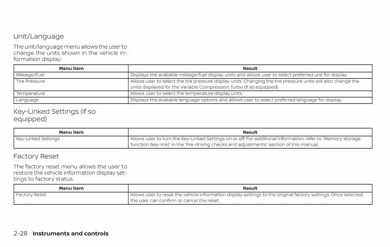
Unit/LanguageThe unit/language menu allows the user tochange the units shown in the vehicle in-formation display.
Menu item ResultMileage/Fuel Displays the available mileage/fuel display units and allows user to select preferred unit for display.Tire Pressure Allows user to select the tire pressure display units. Changing the tire pressure units will also change the
units displayed for the Variable Compression Turbo (if so equipped).Temperature Allows user to select the temperature display units.Language Displays the available language options and allows user to select preferred language for display.
Key-Linked Settings (if soequipped)
Menu item ResultKey-Linked Settings Allows user to turn the Key-Linked Settings on or off. For additional information, refer to “Memory storage
function (key-link)” in the “Pre-driving checks and adjustments” section of this manual.
Factory ResetThe factory reset menu allows the user torestore the vehicle information display set-tings to factory status.
Menu item ResultFactory Reset Allows user to reset the vehicle information display settings to the original factory settings. Once selected,
the user can confirm or cancel the reset.
2-28 Instruments and controls
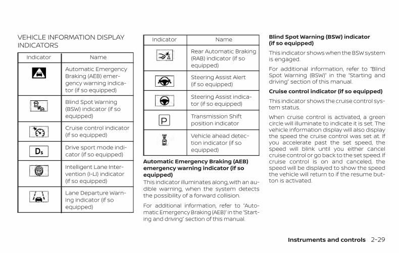
VEHICLE INFORMATION DISPLAYINDICATORS
Indicator Name
Automatic EmergencyBraking (AEB) emer-gency warning indica-tor (if so equipped)
Blind Spot Warning(BSW) indicator (if soequipped)
Cruise control indicator(if so equipped)
Drive sport mode indi-cator (if so equipped)
Intelligent Lane Inter-vention (I-LI) indicator(if so equipped)
Lane Departure Warn-ing indicator (if soequipped)
Indicator Name
Rear Automatic Braking(RAB) indicator (if soequipped)
Steering Assist Alert(if so equipped)
Steering Assist indica-tor (if so equipped)
Transmission Shiftposition indicator
Vehicle ahead detec-tion indicator (if soequipped)
Automatic Emergency Braking (AEB)emergency warning indicator (if soequipped)This indicator illuminates along, with an au-dible warning, when the system detectsthe possibility of a forward collision.
For additional information, refer to “Auto-matic Emergency Braking (AEB)” in the “Start-ing and driving” section of this manual.
Blind Spot Warning (BSW) indicator(if so equipped)
This indicator shows when the BSW systemis engaged.
For additional information, refer to “BlindSpot Warning (BSW)” in the “Starting anddriving” section of this manual.
Cruise control indicator (if so equipped)
This indicator shows the cruise control sys-tem status.
When cruise control is activated, a greencircle will illuminate to indicate it is set. Thevehicle information display will also displaythe speed the cruise control was set at. Ifyou accelerate past the set speed, thespeed will blink until you either cancelcruise control or go back to the set speed. Ifcruise control is on and canceled, thespeed will be displayed to show the speedthe vehicle will return to if the resume but-ton is activated.
Instruments and controls 2-29
Drive sport mode indicator (if soequipped)
A small “S” appears to the right of the Trans-mission Shift Position indicator in the ve-hicle information display when the drivesport mode is engaged.
Activate the drive sport mode by pushingthe switch on the shift lever while the shiftlever is in the D (Drive) position.
For additional information, refer to “Drivingthe vehicle” in the “Starting and driving” sec-tion of this manual.
Intelligent Lane Intervention (I-LI) indi-cator (if so equipped)
This indicator shows when the I-LI systemis engaged.
For additional information, refer to “Intelli-gent Lane Intervention (I-LI)” in the “Startingand driving” section of this manual.
Lane Departure Warning (LDW) indicator(if so equipped)
This indicator shows when the LDW systemis engaged.
For additional information, refer to “LaneDeparture Warning (LDW)” and “IntelligentLane Intervention (I-LI)” in the “Starting anddriving” section of this manual.
Rear Automatic Braking (RAB) indicator(if so equipped)
This indicator illuminates to indicate thestatus of the Rear Automatic Braking (RAB)system. For additional information, refer to“Rear Automatic Braking (RAB)” in the “Start-ing and driving” section of this manual.
Steering Assist Alert (if so equipped)
This message may appear when the Steer-ing Assist system is engaged.
It will be displayed under the following con-dition:
∙ When not holding the steering wheel orwhen there is no steering wheel opera-tion
Please hold on the steering wheel immedi-ately. When the steering operation is de-tected, the warning turns off and the steer-ing assist function is automatically restored.
Steering Assist indicator (if soequipped)
This indicator appears when the SteeringAssist system is engaged.
For additional information, refer to “ProPI-LOT Assist” in the “Starting and driving” sec-tion of this manual.
Transmission Shift Position indicator
This indicator shows the transmission shiftposition.
Vehicle ahead detection indicator (if soequipped)
This indicator shows when the AutomaticEmergency Braking (AEB) system is en-gaged and has detected a vehicle.
For additional information, refer to “Auto-matic Emergency Braking (AEB)” in the “Start-ing and driving” section of this manual.
2-30 Instruments and controls
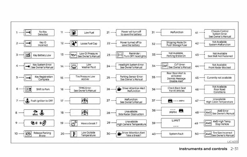
LIC4031
Instruments and controls 2-31
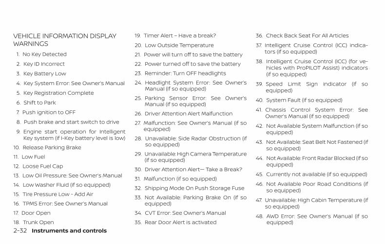
VEHICLE INFORMATION DISPLAYWARNINGS
1. No Key Detected
2. Key ID Incorrect
3. Key Battery Low
4. Key System Error: See Owner’s Manual
5. Key Registration Complete
6. Shift to Park
7. Push ignition to OFF
8. Push brake and start switch to drive
9. Engine start operation for IntelligentKey system (if I-Key battery level is low)
10. Release Parking Brake
11. Low Fuel
12. Loose Fuel Cap
13. Low Oil Pressure: See Owner’s Manual
14. Low Washer Fluid (if so equipped)
15. Tire Pressure Low - Add Air
16. TPMS Error: See Owner’s Manual
17. Door Open
18. Trunk Open
19. Timer Alert – Have a break?
20. Low Outside Temperature
21. Power will turn off to save the battery
22. Power turned off to save the battery
23. Reminder: Turn OFF headlights
24. Headlight System Error: See Owner’sManual (if so equipped)
25. Parking Sensor Error: See Owner’sManual (if so equipped)
26. Driver Attention Alert Malfunction
27. Malfunction: See Owner’s Manual (if soequipped)
28. Unavailable: Side Radar Obstruction (ifso equipped)
29. Unavailable: High Camera Temperature(if so equipped)
30. Driver Attention Alert— Take a Break?
31. Malfunction (if so equipped)
32. Shipping Mode On Push Storage Fuse
33. Not Available: Parking Brake On (if soequipped)
34. CVT Error: See Owner’s Manual
35. Rear Door Alert is activated
36. Check Back Seat For All Articles
37. Intelligent Cruise Control (ICC) indica-tors (if so equipped)
38. Intelligent Cruise Control (ICC) (for ve-hicles with ProPILOT Assist) indicators(if so equipped)
39. Speed Limit Sign indicator (if soequipped)
40. System Fault (if so equipped)
41. Chassis Control System Error: SeeOwner’s Manual (if so equipped)
42. Not Available System Malfunction (if soequipped)
43. Not Available: Seat Belt Not Fastened (ifso equipped)
44. Not Available: Front Radar Blocked (if soequipped)
45. Currently not available (if so equipped)
46. Not Available Poor Road Conditions (ifso equipped)
47. Unavailable: High Cabin Temperature (ifso equipped)
48. AWD Error: See Owner’s Manual (if soequipped)
2-32 Instruments and controls
49. AWD High Temp. Stop vehicle (if soequipped)
50. AWD Tire Size Incorrect: See Owner’sManual (if so equipped)
No Key Detected
This warning appears when the IntelligentKey is left outside the vehicle with the igni-tion switch in the ON position. Make surethe Intelligent Key is inside the vehicle.
For additional information, refer to “NISSANIntelligent Key®” in the “Pre-driving checksand adjustments” section of this manual.
Key ID Incorrect
This warning appears when the ignitionswitch is placed from the OFF position andthe Intelligent Key is not recognized by thesystem. You cannot start the engine withan unregistered key.
For additional information, refer to “NISSANIntelligent Key®” in the “Pre-driving checksand adjustments” section of this manual.
Key Battery Low
This indicator illuminates when the Intelli-gent Key battery is running out of power.
If this indicator illuminates, replace the bat-tery with a new one. For additional infor-
mation, refer to “Battery replacement” inthe “Do-it-yourself ” section of this manual.
Key System Error: See Owner’s Manual
After the ignition switch is pushed to theON position, this light comes on for a periodof time and then turns off.
The Key System Error message warns of amalfunction with the Intelligent Key sys-tem. If the light comes on while the engineis stopped, it may be impossible to startthe engine.
If the light comes on while the engine isrunning, you can drive the vehicle. However,in these cases, have the system checked. Itis recommended that you visit a NISSANdealer for this service.
Key Registration Complete
This appears when a new Intelligent Key isregistered to the vehicle.
Shift to Park
This warning illuminates when the ignitionswitch is in the AUTO ACC or OFF positionand the shift lever is not in the P (Park)position. Also, a chime sounds when theignition switch is in the AUTO ACC or OFFposition.
If this warning illuminates, move the shiftlever to the P (Park) position and start theengine.
Push Ignition to OFF
After the Push Ignition to OFF warning illu-minates, the warning will illuminate if theignition switch is placed in the AUTO ACCposition when the shift lever is moved tothe P (Park) position.
To turn off the Push warning, place the ig-nition switch in the ON position and then inthe LOCK position.
Push brake and start switch to drive
This indicator appears when the shift leveris in the P (Park) position.
This indicator also appears when the ve-hicle has been started using the RemoteEngine Start (if so equipped) function.
This indicator means that the engine willstart by pushing the ignition switch withthe brake pedal depressed. You can startthe engine from any position of the ignitionswitch.
Instruments and controls 2-33
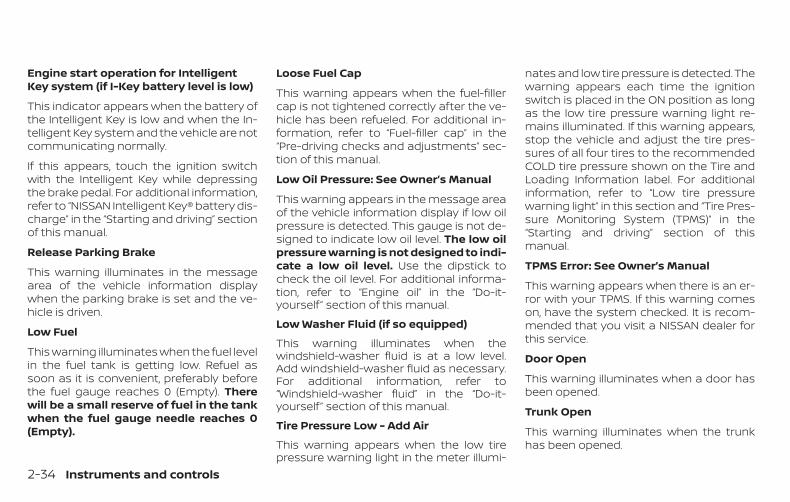
Engine start operation for IntelligentKey system (if I-Key battery level is low)
This indicator appears when the battery ofthe Intelligent Key is low and when the In-telligent Key system and the vehicle are notcommunicating normally.
If this appears, touch the ignition switchwith the Intelligent Key while depressingthe brake pedal. For additional information,refer to “NISSAN Intelligent Key® battery dis-charge” in the “Starting and driving” sectionof this manual.
Release Parking Brake
This warning illuminates in the messagearea of the vehicle information displaywhen the parking brake is set and the ve-hicle is driven.
Low Fuel
This warning illuminates when the fuel levelin the fuel tank is getting low. Refuel assoon as it is convenient, preferably beforethe fuel gauge reaches 0 (Empty). Therewill be a small reserve of fuel in the tankwhen the fuel gauge needle reaches 0(Empty).
Loose Fuel Cap
This warning appears when the fuel-fillercap is not tightened correctly after the ve-hicle has been refueled. For additional in-formation, refer to “Fuel-filler cap” in the“Pre-driving checks and adjustments” sec-tion of this manual.
Low Oil Pressure: See Owner’s Manual
This warning appears in the message areaof the vehicle information display if low oilpressure is detected. This gauge is not de-signed to indicate low oil level. The low oilpressure warning is not designed to indi-cate a low oil level. Use the dipstick tocheck the oil level. For additional informa-tion, refer to “Engine oil” in the “Do-it-yourself ” section of this manual.
Low Washer Fluid (if so equipped)
This warning illuminates when thewindshield-washer fluid is at a low level.Add windshield-washer fluid as necessary.For additional information, refer to“Windshield-washer fluid” in the “Do-it-yourself ” section of this manual.
Tire Pressure Low - Add Air
This warning appears when the low tirepressure warning light in the meter illumi-
nates and low tire pressure is detected. Thewarning appears each time the ignitionswitch is placed in the ON position as longas the low tire pressure warning light re-mains illuminated. If this warning appears,stop the vehicle and adjust the tire pres-sures of all four tires to the recommendedCOLD tire pressure shown on the Tire andLoading Information label. For additionalinformation, refer to “Low tire pressurewarning light” in this section and “Tire Pres-sure Monitoring System (TPMS)” in the“Starting and driving” section of thismanual.
TPMS Error: See Owner’s Manual
This warning appears when there is an er-ror with your TPMS. If this warning comeson, have the system checked. It is recom-mended that you visit a NISSAN dealer forthis service.
Door Open
This warning illuminates when a door hasbeen opened.
Trunk Open
This warning illuminates when the trunkhas been opened.
2-34 Instruments and controls
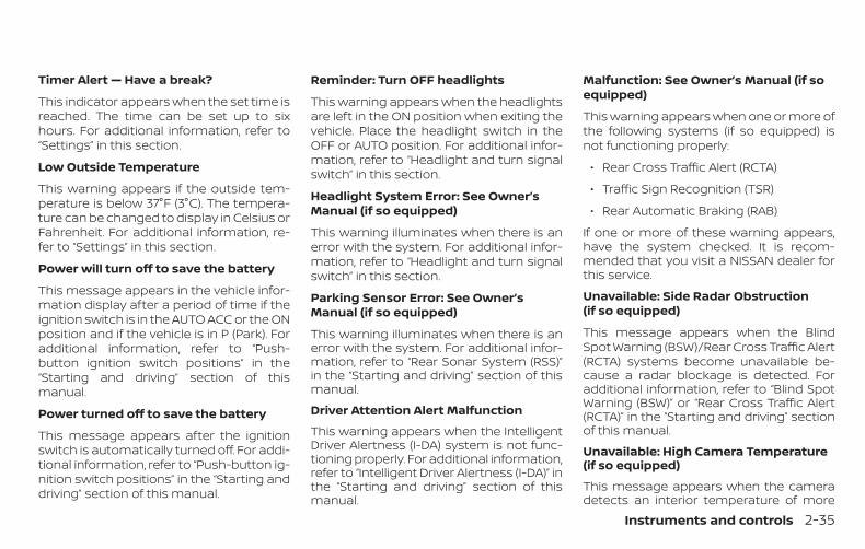
Timer Alert — Have a break?
This indicator appears when the set time isreached. The time can be set up to sixhours. For additional information, refer to“Settings” in this section.
Low Outside Temperature
This warning appears if the outside tem-perature is below 37°F (3°C). The tempera-ture can be changed to display in Celsius orFahrenheit. For additional information, re-fer to “Settings” in this section.
Power will turn off to save the battery
This message appears in the vehicle infor-mation display after a period of time if theignition switch is in the AUTO ACC or the ONposition and if the vehicle is in P (Park). Foradditional information, refer to “Push-button ignition switch positions” in the“Starting and driving” section of thismanual.
Power turned off to save the battery
This message appears after the ignitionswitch is automatically turned off. For addi-tional information, refer to “Push-button ig-nition switch positions” in the “Starting anddriving” section of this manual.
Reminder: Turn OFF headlights
This warning appears when the headlightsare left in the ON position when exiting thevehicle. Place the headlight switch in theOFF or AUTO position. For additional infor-mation, refer to “Headlight and turn signalswitch” in this section.
Headlight System Error: See Owner’sManual (if so equipped)
This warning illuminates when there is anerror with the system. For additional infor-mation, refer to “Headlight and turn signalswitch” in this section.
Parking Sensor Error: See Owner’sManual (if so equipped)
This warning illuminates when there is anerror with the system. For additional infor-mation, refer to “Rear Sonar System (RSS)”in the “Starting and driving” section of thismanual.
Driver Attention Alert Malfunction
This warning appears when the IntelligentDriver Alertness (I-DA) system is not func-tioning properly. For additional information,refer to “Intelligent Driver Alertness (I-DA)” inthe “Starting and driving” section of thismanual.
Malfunction: See Owner’s Manual (if soequipped)
This warning appears when one or more ofthe following systems (if so equipped) isnot functioning properly:
∙ Rear Cross Traffic Alert (RCTA)
∙ Traffic Sign Recognition (TSR)
∙ Rear Automatic Braking (RAB)
If one or more of these warning appears,have the system checked. It is recom-mended that you visit a NISSAN dealer forthis service.
Unavailable: Side Radar Obstruction(if so equipped)
This message appears when the BlindSpot Warning (BSW)/Rear Cross Traffic Alert(RCTA) systems become unavailable be-cause a radar blockage is detected. Foradditional information, refer to “Blind SpotWarning (BSW)” or “Rear Cross Traffic Alert(RCTA)” in the “Starting and driving” sectionof this manual.
Unavailable: High Camera Temperature(if so equipped)
This message appears when the cameradetects an interior temperature of more
Instruments and controls 2-35
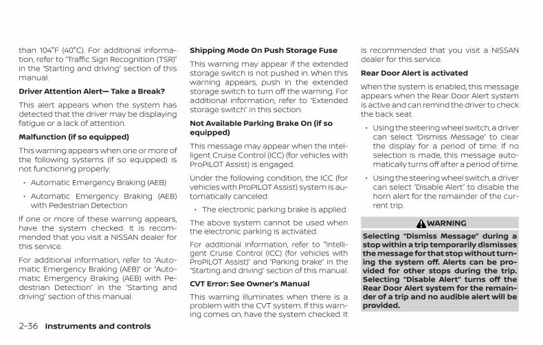
than 104°F (40°C). For additional informa-tion, refer to “Traffic Sign Recognition (TSR)”in the “Starting and driving” section of thismanual.
Driver Attention Alert— Take a Break?
This alert appears when the system hasdetected that the driver may be displayingfatigue or a lack of attention.
Malfunction (if so equipped)
This warning appears when one or more ofthe following systems (if so equipped) isnot functioning properly:
∙ Automatic Emergency Braking (AEB)
∙ Automatic Emergency Braking (AEB)with Pedestrian Detection
If one or more of these warning appears,have the system checked. It is recom-mended that you visit a NISSAN dealer forthis service.
For additional information, refer to “Auto-matic Emergency Braking (AEB)” or “Auto-matic Emergency Braking (AEB) with Pe-destrian Detection” in the “Starting anddriving” section of this manual.
Shipping Mode On Push Storage Fuse
This warning may appear if the extendedstorage switch is not pushed in. When thiswarning appears, push in the extendedstorage switch to turn off the warning. Foradditional information, refer to “Extendedstorage switch” in this section.
Not Available Parking Brake On (if soequipped)
This message may appear when the Intel-ligent Cruise Control (ICC) (for vehicles withProPILOT Assist) is engaged.
Under the following condition, the ICC (forvehicles with ProPILOT Assist) system is au-tomatically canceled:
∙ The electronic parking brake is applied.
The above system cannot be used whenthe electronic parking is activated.
For additional information, refer to "Intelli-gent Cruise Control (ICC) (for vehicles withProPILOT Assist)” and “Parking brake” in the“Starting and driving” section of this manual.
CVT Error: See Owner’s Manual
This warning illuminates when there is aproblem with the CVT system. If this warn-ing comes on, have the system checked. It
is recommended that you visit a NISSANdealer for this service.
Rear Door Alert is activated
When the system is enabled, this messageappears when the Rear Door Alert systemis active and can remind the driver to checkthe back seat.
∙ Using the steering wheel switch, a drivercan select “Dismiss Message” to clearthe display for a period of time. If noselection is made, this message auto-matically turns off after a period of time.
∙ Using the steering wheel switch, a drivercan select “Disable Alert” to disable thehorn alert for the remainder of the cur-rent trip.
WARNINGSelecting “Dismiss Message” during astop within a trip temporarily dismissesthe message for that stop without turn-ing the system off. Alerts can be pro-vided for other stops during the trip.Selecting “Disable Alert” turns off theRear Door Alert system for the remain-der of a trip and no audible alert will beprovided.
2-36 Instruments and controls
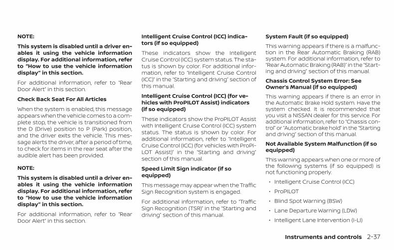
NOTE:
This system is disabled until a driver en-ables it using the vehicle informationdisplay. For additional information, referto “How to use the vehicle informationdisplay” in this section.
For additional information, refer to “RearDoor Alert” in this section.
Check Back Seat For All Articles
When the system is enabled, this messageappears when the vehicle comes to a com-plete stop, the vehicle is transitioned fromthe D (Drive) position to P (Park) position,and the driver exits the vehicle. This mes-sage alerts the driver, after a period of time,to check for items in the rear seat after theaudible alert has been provided.
NOTE:
This system is disabled until a driver en-ables it using the vehicle informationdisplay. For additional information, referto “How to use the vehicle informationdisplay” in this section.
For additional information, refer to “RearDoor Alert” in this section.
Intelligent Cruise Control (ICC) indica-tors (if so equipped)
These indicators show the IntelligentCruise Control (ICC) system status. The sta-tus is shown by color. For additional infor-mation, refer to “Intelligent Cruise Control(ICC)” in the “Starting and driving” section ofthis manual.
Intelligent Cruise Control (ICC) (for ve-hicles with ProPILOT Assist) indicators(if so equipped)
These indicators show the ProPILOT Assistwith Intelligent Cruise Control (ICC) systemstatus. The status is shown by color. Foradditional information, refer to “IntelligentCruise Control (ICC) (for vehicles with ProPI-LOT Assist)” in the “Starting and driving”section of this manual.
Speed Limit Sign indicator (if soequipped)
This message may appear when the TrafficSign Recognition system is engaged.
For additional information, refer to “TrafficSign Recognition (TSR)” in the “Starting anddriving” section of this manual.
System Fault (if so equipped)
This warning appears if there is a malfunc-tion in the Rear Automatic Braking (RAB)system. For additional information, refer to“Rear Automatic Braking (RAB)” in the “Start-ing and driving” section of this manual.
Chassis Control System Error: SeeOwner’s Manual (if so equipped)
This warning appears if there is an error inthe Automatic Brake Hold system. Have thesystem checked. It is recommended thatyou visit a NISSAN dealer for this service. Foradditional information, refer to “Chassis con-trol” or “Automatic brake hold” in the “Startingand driving” section of this manual.
Not Available System Malfunction (if soequipped)
This warning appears when one or more ofthe following systems (if so equipped) isnot functioning properly.
∙ Intelligent Cruise Control (ICC)
∙ ProPILOT
∙ Blind Spot Warning (BSW)
∙ Lane Departure Warning (LDW)
∙ Intelligent Lane Intervention (I-LI)
Instruments and controls 2-37
If one or more of these warnings appear,have the system checked. It is recom-mended that you visit a NISSAN dealer forthis service.
For additional information, refer to "Intelli-gent Cruise Control (ICC)” , “ProPILOT Assist”, “Blind Spot Warning (BSW)” , “Lane Depar-ture Warning (LDW)” or “Intelligent Lane In-tervention (I-LI))” in the “Starting and driving”section of this manual.
Not Available Seat Belt Not Fastened(if so equipped)
This message may appear when the Intel-ligent Cruise Control (ICC) (with ProPILOTAssist) system is engaged.
Under the following condition, the ICC (withProPILOT Assist) system is automaticallycanceled:
∙ When the driver’s seat belt is not fas-tened
The above system cannot be used whenthe driver’s seat belt is not fastened.
Not Available: Front Radar Blocked (if soequipped)
This message appears when the IntelligentCruise Control (ICC) systems, the Auto-matic Emergency Braking (AEB) system,
the Automatic Emergency Braking (AEB)with Pedestrian Detection system, or theIntelligent Forward Collision Warning (I-FCW) system becomes unavailable be-cause the front radar is obstructed. For ad-ditional information, refer to “IntelligentCruise Control (ICC) (for vehicles withoutProPILOT Assist)” , “Intelligent Cruise Control(ICC) (for vehicles with ProPILOT Assist)” ,“Automatic Emergency Braking (AEB)” , “Au-tomatic Emergency Braking (AEB) with Pe-destrian Detection” or “Intelligent ForwardCollision Warning (I-FCW)” in the “Startingand driving” section of this manual.
Currently not available (if so equipped)
This message may appear when the Intel-ligent Cruise Control (ICC) (with ProPILOTAssist) system , the ICC system or the Intel-ligent Lane Intervention (I-LI) system is en-gaged.
Under the following conditions, the ICC(with ProPILOT Assist) , the ICC system orthe Intelligent Lane Intervention (I-LI) sys-tem is automatically canceled:
∙ When the VDC operates
∙ When a wheel slips
∙ When the VDC system is turned off
The above system cannot be used in somesituations (VDC operates, wheel slip andVDC system is off.)
Not Available Poor Road Conditions (ifso equipped)
This message may appear when the Intel-ligent Cruise Control (ICC) (with ProPILOTAssist) system , the ICC system or the Intel-ligent Lane Intervention (I-LI) system is en-gaged.
Under the following conditions, the ICC(with ProPILOT Assist) , the ICC system orthe Intelligent Lane Intervention (I-LI) sys-tem is automatically canceled:
∙ When the VDC operates
∙ When a wheel slips
The above system cannot be used in somesituations (VDC operates and wheel slip.)
Unavailable: High Cabin Temperature (ifso equipped)
This message appears when the cameradetects an interior temperature of morethan approximately 104°F (40°C). For addi-tional information, refer to “Lane DepartureWarning (LDW)” and “Intelligent Lane Inter-vention (I-LI)” in the “Starting and driving”section of this manual.
2-38 Instruments and controls
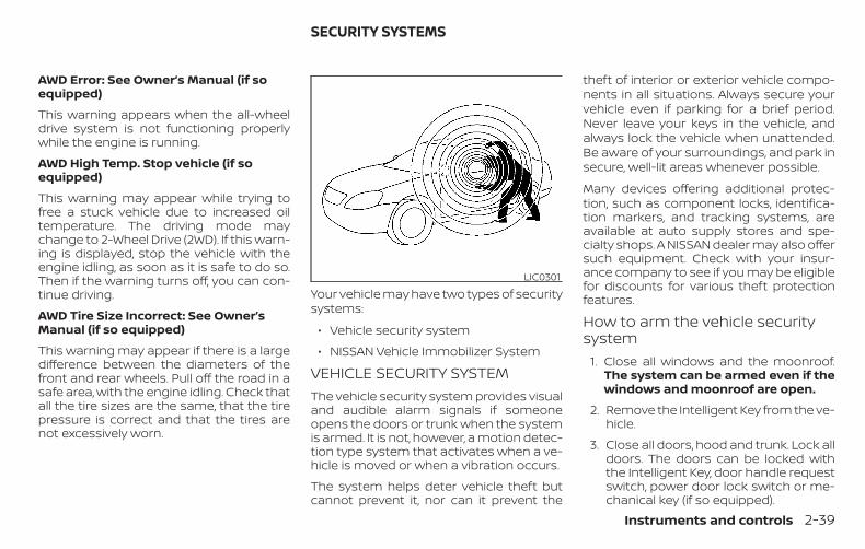
AWD Error: See Owner’s Manual (if soequipped)
This warning appears when the all-wheeldrive system is not functioning properlywhile the engine is running.
AWD High Temp. Stop vehicle (if soequipped)
This warning may appear while trying tofree a stuck vehicle due to increased oiltemperature. The driving mode maychange to 2-Wheel Drive (2WD). If this warn-ing is displayed, stop the vehicle with theengine idling, as soon as it is safe to do so.Then if the warning turns off, you can con-tinue driving.
AWD Tire Size Incorrect: See Owner’sManual (if so equipped)
This warning may appear if there is a largedifference between the diameters of thefront and rear wheels. Pull off the road in asafe area, with the engine idling. Check thatall the tire sizes are the same, that the tirepressure is correct and that the tires arenot excessively worn.
Your vehicle may have two types of securitysystems:
∙ Vehicle security system
∙ NISSAN Vehicle Immobilizer System
VEHICLE SECURITY SYSTEMThe vehicle security system provides visualand audible alarm signals if someoneopens the doors or trunk when the systemis armed. It is not, however, a motion detec-tion type system that activates when a ve-hicle is moved or when a vibration occurs.
The system helps deter vehicle theft butcannot prevent it, nor can it prevent the
theft of interior or exterior vehicle compo-nents in all situations. Always secure yourvehicle even if parking for a brief period.Never leave your keys in the vehicle, andalways lock the vehicle when unattended.Be aware of your surroundings, and park insecure, well-lit areas whenever possible.
Many devices offering additional protec-tion, such as component locks, identifica-tion markers, and tracking systems, areavailable at auto supply stores and spe-cialty shops. A NISSAN dealer may also offersuch equipment. Check with your insur-ance company to see if you may be eligiblefor discounts for various theft protectionfeatures.
How to arm the vehicle securitysystem
1. Close all windows and the moonroof.The system can be armed even if thewindows and moonroof are open.
2. Remove the Intelligent Key from the ve-hicle.
3. Close all doors, hood and trunk. Lock alldoors. The doors can be locked withthe Intelligent Key, door handle requestswitch, power door lock switch or me-chanical key (if so equipped).
LIC0301
SECURITY SYSTEMS
Instruments and controls 2-39
4. Confirm that the indicator lightcomes on. The indicator stays il-luminated for a period of time indicat-ing that the system is in the pre-armedphase.The indicator light will blink every3 seconds once the security system isarmed.If during the pre-armed phase one ofthe following occurs, the system willnot arm:
∙ Any door is unlocked with the me-chanical key (if so equipped), Intelli-gent Key or door request switch.
∙ The ignition switch is placed in theAUTO ACC or ON position.
∙ Even when the driver and/or passen-gers are in the vehicle, the system willactivate when all the doors, hood andtrunk are locked with the ignitionswitch placed in the LOCK position.When placing the ignition switch inthe AUTO new ACC or ON position, thesystem will be released.
Vehicle security system activationThe vehicle security system will give thefollowing alarm:
∙ The headlights blink and the hornsounds intermittently.
∙ The alarm automatically turns off aftera period of time. However, the alarmreactivates if the vehicle is tamperedwith again. The alarm can be shut off byunlocking the driver’s door or trunk lidwith the key, or by pressing thebutton on the Intelligent Key.
The alarm is activated by:
∙ opening the door or trunk lid withoutusing the key or Intelligent Key (even ifthe door is unlocked by releasing thedoor inside lock switch).
How to stop an activated alarmThe alarm stops only by unlocking a dooror the trunk with the mechanical key (if soequipped), pressing the button onthe Intelligent Key, or pushing the requestswitch on the driver’s or passenger’s doorwith the Intelligent Key in range of the doorhandle.
NISSAN VEHICLE IMMOBILIZERSYSTEMThe NISSAN Vehicle Immobilizer Systemwill not allow the engine to start withoutthe use of a registered key.
If the engine fails to start using a registeredkey (for example, when interference iscaused by another registered key, an auto-mated toll road device or automatic pay-ment device on the key ring), restart theengine using the following procedures:
1. Leave the ignition switch placed in theON position for approximately 5 sec-onds.
2. Place the ignition switch in the OFF orLOCK position, and wait approximately10 seconds.
3. Repeat Steps 1 and 2.
4. Restart the engine while holding thedevice (which may have caused the in-terference) separate from the regis-tered key.
If the no start condition re-occurs, NISSANrecommends placing the registered key ona separate key ring to avoid interferencefrom other devices.
2-40 Instruments and controls
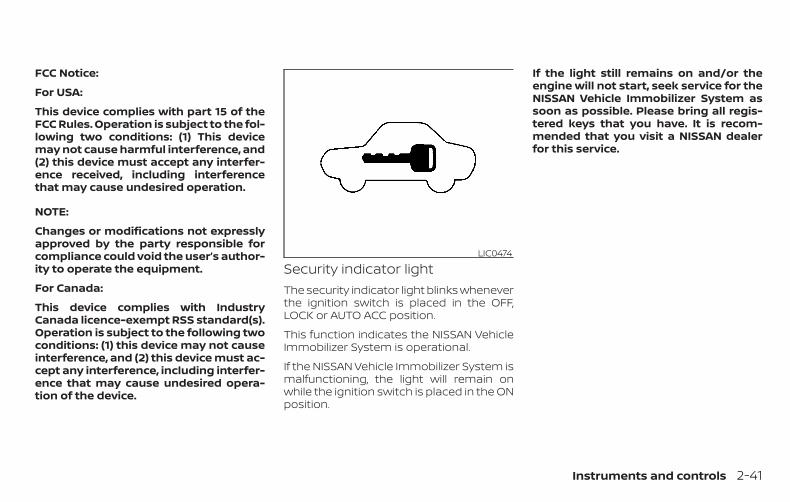
FCC Notice:
For USA:
This device complies with part 15 of theFCC Rules. Operation is subject to the fol-lowing two conditions: (1) This devicemay not cause harmful interference, and(2) this device must accept any interfer-ence received, including interferencethat may cause undesired operation.
NOTE:
Changes or modifications not expresslyapproved by the party responsible forcompliance could void the user’s author-ity to operate the equipment.
For Canada:
This device complies with IndustryCanada licence-exempt RSS standard(s).Operation is subject to the following twoconditions: (1) this device may not causeinterference, and (2) this device must ac-cept any interference, including interfer-ence that may cause undesired opera-tion of the device.
Security indicator lightThe security indicator light blinks wheneverthe ignition switch is placed in the OFF,LOCK or AUTO ACC position.
This function indicates the NISSAN VehicleImmobilizer System is operational.
If the NISSAN Vehicle Immobilizer System ismalfunctioning, the light will remain onwhile the ignition switch is placed in the ONposition.
If the light still remains on and/or theengine will not start, seek service for theNISSAN Vehicle Immobilizer System assoon as possible. Please bring all regis-tered keys that you have. It is recom-mended that you visit a NISSAN dealerfor this service.
LIC0474
Instruments and controls 2-41
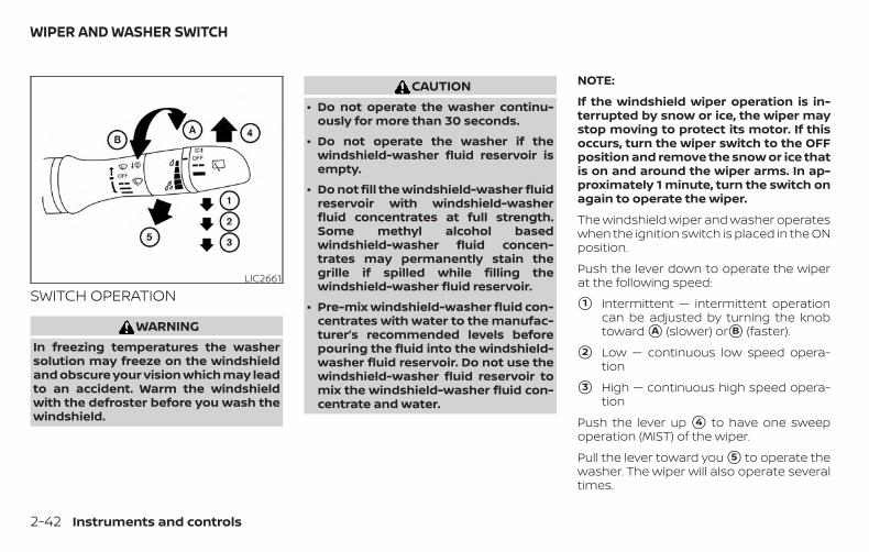
SWITCH OPERATION
WARNINGIn freezing temperatures the washersolution may freeze on the windshieldand obscure your vision which may leadto an accident. Warm the windshieldwith the defroster before you wash thewindshield.
CAUTION∙ Do not operate the washer continu-
ously for more than 30 seconds.
∙ Do not operate the washer if thewindshield-washer fluid reservoir isempty.
∙ Do not fill the windshield-washer fluidreservoir with windshield-washerfluid concentrates at full strength.Some methyl alcohol basedwindshield-washer fluid concen-trates may permanently stain thegrille if spilled while filling thewindshield-washer fluid reservoir.
∙ Pre-mix windshield-washer fluid con-centrates with water to the manufac-turer’s recommended levels beforepouring the fluid into the windshield-washer fluid reservoir. Do not use thewindshield-washer fluid reservoir tomix the windshield-washer fluid con-centrate and water.
NOTE:
If the windshield wiper operation is in-terrupted by snow or ice, the wiper maystop moving to protect its motor. If thisoccurs, turn the wiper switch to the OFFposition and remove the snow or ice thatis on and around the wiper arms. In ap-proximately 1 minute, turn the switch onagain to operate the wiper.
The windshield wiper and washer operateswhen the ignition switch is placed in the ONposition.
Push the lever down to operate the wiperat the following speed:
�1 Intermittent — intermittent operationcan be adjusted by turning the knobtoward �A (slower) or�B (faster).
�2 Low — continuous low speed opera-tion
�3 High — continuous high speed opera-tion
Push the lever up �4 to have one sweepoperation (MIST) of the wiper.
Pull the lever toward you �5 to operate thewasher. The wiper will also operate severaltimes.
LIC2661
WIPER AND WASHER SWITCH
2-42 Instruments and controls
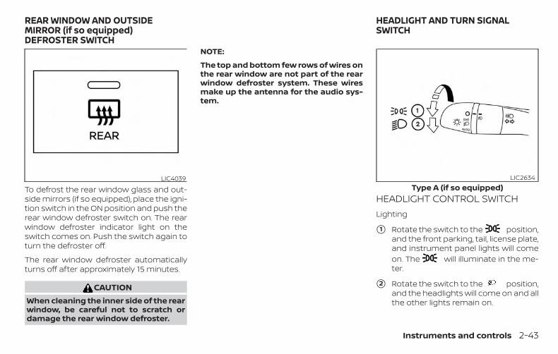
To defrost the rear window glass and out-side mirrors (if so equipped), place the igni-tion switch in the ON position and push therear window defroster switch on. The rearwindow defroster indicator light on theswitch comes on. Push the switch again toturn the defroster off.
The rear window defroster automaticallyturns off after approximately 15 minutes.
CAUTIONWhen cleaning the inner side of the rearwindow, be careful not to scratch ordamage the rear window defroster.
NOTE:
The top and bottom few rows of wires onthe rear window are not part of the rearwindow defroster system. These wiresmake up the antenna for the audio sys-tem.
HEADLIGHT CONTROL SWITCHLighting
�1 Rotate the switch to the position,and the front parking, tail, license plate,and instrument panel lights will comeon. The will illuminate in the me-ter.
�2 Rotate the switch to the position,and the headlights will come on and allthe other lights remain on.
LIC4039Type A (if so equipped)
LIC2634
REAR WINDOW AND OUTSIDEMIRROR (if so equipped)DEFROSTER SWITCH
HEADLIGHT AND TURN SIGNALSWITCH
Instruments and controls 2-43
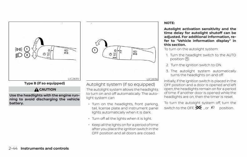
CAUTIONUse the headlights with the engine run-ning to avoid discharging the vehiclebattery.
Autolight system (if so equipped)The autolight system allows the headlightsto turn on and off automatically. The auto-light system can:
∙ Turn on the headlights, front parking,tail, license plate and instrument panellights automatically when it is dark.
∙ Turn off all the lights when it is light.
∙ Keep all the lights on for a period of timeafter you place the ignition switch in theOFF position and all doors are closed.
NOTE:
Autolight activation sensitivity and thetime delay for autolight shutoff can beadjusted. For additional information, re-fer to “Vehicle information display” inthis section.To turn on the autolight system:
1. Turn the headlight switch to the AUTOposition �1 .
2. Turn the ignition switch to ON.
3. The autolight system automaticallyturns the headlights on and off.
Initially, if the ignition switch is placed in theOFF position and a door is opened and leftopen, the headlights remain on for a periodof time. If another door is opened while theheadlights are on, then the timer is reset.
To turn the autolight system off, turn theswitch to the OFF, , or position.
Type B (if so equipped)LIC2635 LIC2636
2-44 Instruments and controls
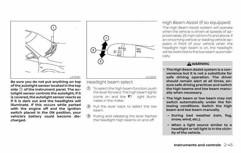
Be sure you do not put anything on topof the autolight sensor located in the topside �1 of the instrument panel. The au-tolight sensor controls the autolight; if itis covered, the autolight sensor reacts asif it is dark out and the headlights willilluminate. If this occurs while parkedwith the engine off and the ignitionswitch placed in the ON position, yourvehicle’s battery could become dis-charged.
Headlight beam select�1 To select the high beam function, push
the lever forward. The high beam lightscome on and the light illumi-nates in the meter.
�2 Pull the lever back to select the lowbeam.
�3 Pulling and releasing the lever flashesthe headlight high beams on and off.
High Beam Assist (if so equipped)The High Beam Assist system will operatewhen the vehicle is driven at speeds of ap-proximately 25 mph (40 km/h) and above. Ifan oncoming vehicle or leading vehicle ap-pears in front of your vehicle when theheadlight high beam is on, the headlightwill be switched to the low beam automati-cally.
WARNING∙ The High Beam Assist system is a con-
venience but it is not a substitute forsafe driving operation. The drivershould remain alert at all times, en-sure safe driving practices and switchthe high beams and low beam manu-ally when necessary.
∙ The high beam or low beam may notswitch automatically under the fol-lowing conditions. Switch the highbeam and low beam manually.
– During bad weather (rain, fog,snow, wind, etc.).
– When a light source similar to aheadlight or tail light is in the vicin-ity of the vehicle.
LIC3051 LIC2637
Instruments and controls 2-45
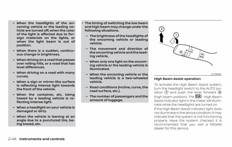
– When the headlights of the on-coming vehicle or the leading ve-hicle are turned off, when the colorof the light is affected due to for-eign materials on the lights, orwhen the light beam is out ofposition.
– When there is a sudden, continu-ous change in brightness.
– When driving on a road that passesover rolling hills, or a road that haslevel differences.
– When driving on a road with manycurves.
– When a sign or mirror-like surfaceis reflecting intense light towardsthe front of the vehicle.
– When the container, etc. beingtowed by a leading vehicle is re-flecting intense light.
– When a headlight on your vehicle isdamaged or dirty.
– When the vehicle is leaning at anangle due to a punctured tire, be-ing towed, etc.
∙ The timing of switching the low beamand high beam may change under thefollowing situations.
– The brightness of the headlights ofthe oncoming vehicle or leadingvehicle.
– The movement and direction ofthe oncoming vehicle and the lead-ing vehicle.
– When only one light on the oncom-ing vehicle or the leading vehicle isilluminated.
– When the oncoming vehicle or theleading vehicle is a two-wheeledvehicle.
– Road conditions (incline, curve, theroad surface, etc.).
– The number of passengers and theamount of luggage.
High Beam Assist operation
To activate the High Beam Assist system,turn the headlight switch to the AUTO po-sition �1 and push the lever forward �2
(high beam position). The High BeamAssist indicator light in the meter will illumi-nate while the headlights are turned on.If the High Beam Assist indicator light doesnot illuminate in the above condition, it mayindicate that the system is not functioningproperly. Have the system checked, it isrecommended that you visit a NISSANdealer for this service.
LIC3696
2-46 Instruments and controls
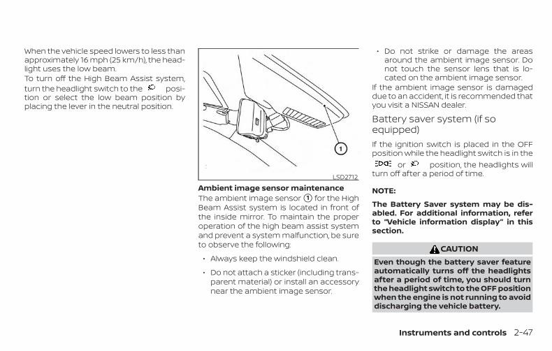
When the vehicle speed lowers to less thanapproximately 16 mph (25 km/h), the head-light uses the low beam.To turn off the High Beam Assist system,turn the headlight switch to the posi-tion or select the low beam position byplacing the lever in the neutral position.
Ambient image sensor maintenanceThe ambient image sensor �1 for the HighBeam Assist system is located in front ofthe inside mirror. To maintain the properoperation of the high beam assist systemand prevent a system malfunction, be sureto observe the following:
∙ Always keep the windshield clean.
∙ Do not attach a sticker (including trans-parent material) or install an accessorynear the ambient image sensor.
∙ Do not strike or damage the areasaround the ambient image sensor. Donot touch the sensor lens that is lo-cated on the ambient image sensor.
If the ambient image sensor is damageddue to an accident, it is recommended thatyou visit a NISSAN dealer.
Battery saver system (if soequipped)If the ignition switch is placed in the OFFposition while the headlight switch is in the
or position, the headlights willturn off after a period of time.
NOTE:
The Battery Saver system may be dis-abled. For additional information, referto “Vehicle information display” in thissection.
CAUTIONEven though the battery saver featureautomatically turns off the headlightsafter a period of time, you should turnthe headlight switch to the OFF positionwhen the engine is not running to avoiddischarging the vehicle battery.
LSD2712
Instruments and controls 2-47
DAYTIME RUNNING LIGHTS (DRL)SYSTEM (Type A) (if so equipped)The Daytime Running Lights (DRL) automati-cally illuminate when the engine is startedwith the parking brake released. The DRLoperate with the headlight switch in theOFF position. Turn the headlight switch tothe position for full illumination whendriving at night. (The DRL will turn off.)If the parking brake is applied before theengine is started, the DRL do not illuminate.The DRL illuminate once the parking brakeis released. The DRL will remain on until theignition switch is placed in the OFF position.
It is necessary at dusk to turn the headlightswitch ON for interior controls andswitches to illuminate, as those remainOFF while the switch is in the OFF position.
WARNINGWhen the DRL system is active, taillights on your vehicle are not on. It isnecessary at dusk to turn on your head-lights. Failure to do so could cause anaccident injuring yourself and others.
LED DAYTIME RUNNING LIGHTS(DRL) SYSTEM (Type B) (if soequipped)The LED DRL automatically illuminate at100% intensity when the engine is startedand the parking brake released. The LEDDaytime Running Lights (DRL) operate withthe headlight switch in the OFF position.When you turn the headlight switch tothe position for full illumination, theLED lights switch from LED DRL to the parkfunction.If the parking brake is applied before theengine is started, the LED DRL do not illumi-nate. The LED DRL illuminate when theparking brake is released. The LED DRL willremain on until the ignition switch is placedin the OFF position.
It is necessary at dusk to turn the headlightswitch ON for interior controls andswitches to illuminate, as those remainOFF while the switch is in the OFF position.
WARNINGWhen the LED DRL system is active, taillights on your vehicle are not on. It isnecessary at dusk to turn on your head-lights. Failure to do so could cause anaccident injuring yourself and others.
2-48 Instruments and controls
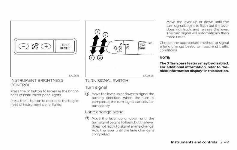
INSTRUMENT BRIGHTNESSCONTROLPress the “+” button to increase the bright-ness of instrument panel lights.
Press the “-” button to decrease the bright-ness of instrument panel lights.
TURN SIGNAL SWITCHTurn signal
�1 Move the lever up or down to signal theturning direction. When the turn iscompleted, the turn signal cancels au-tomatically.
Lane change signal
�2 Move the lever up or down until theturn signal begins to flash, but the leverdoes not latch, to signal a lane change.Hold the lever until the lane change iscompleted.
Move the lever up or down until theturn signal begins to flash, but the leverdoes not latch, and release the lever.The turn signal will automatically flashthree times.
Choose the appropriate method to signala lane change based on road and trafficconditions.
NOTE:
The 3 flash pass feature may be disabled.For additional information, refer to “Ve-hicle information display” in this section.
LIC3176 LIC2638
Instruments and controls 2-49
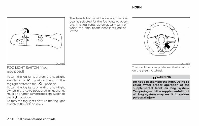
FOG LIGHT SWITCH (if soequipped)To turn the fog lights on, turn the headlightswitch to the position, then turn thefog light switch to the position.To turn the fog lights on with the headlightswitch in the AUTO position, the headlightsmust be on, then turn the fog light switch tothe position.To turn the fog lights off, turn the fog lightswitch to the OFF position.
The headlights must be on and the lowbeams selected for the fog lights to oper-ate. The fog lights automatically turn offwhen the high beam headlights are se-lected.
To sound the horn, push near the horn iconon the steering wheel.
WARNINGDo not disassemble the horn. Doing socould affect proper operation of thesupplemental front air bag system.Tampering with the supplemental frontair bag system may result in seriouspersonal injury.
LIC2639 LIC3568
HORN
2-50 Instruments and controls
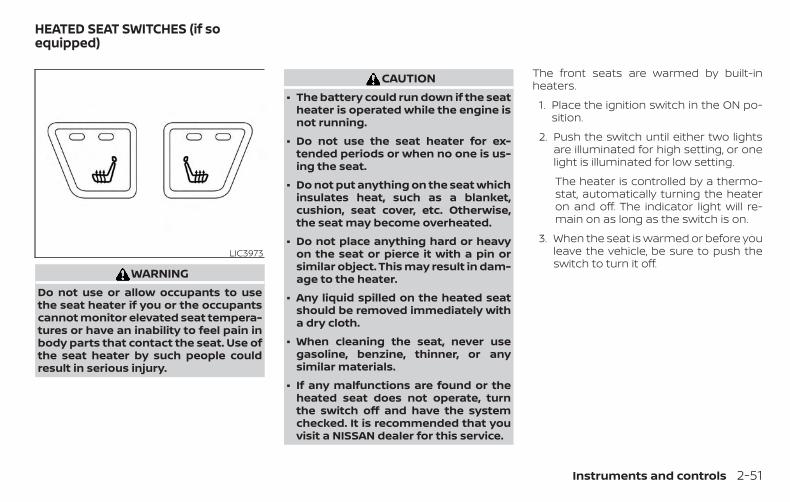
WARNINGDo not use or allow occupants to usethe seat heater if you or the occupantscannot monitor elevated seat tempera-tures or have an inability to feel pain inbody parts that contact the seat. Use ofthe seat heater by such people couldresult in serious injury.
CAUTION∙ The battery could run down if the seat
heater is operated while the engine isnot running.
∙ Do not use the seat heater for ex-tended periods or when no one is us-ing the seat.
∙ Do not put anything on the seat whichinsulates heat, such as a blanket,cushion, seat cover, etc. Otherwise,the seat may become overheated.
∙ Do not place anything hard or heavyon the seat or pierce it with a pin orsimilar object. This may result in dam-age to the heater.
∙ Any liquid spilled on the heated seatshould be removed immediately witha dry cloth.
∙ When cleaning the seat, never usegasoline, benzine, thinner, or anysimilar materials.
∙ If any malfunctions are found or theheated seat does not operate, turnthe switch off and have the systemchecked. It is recommended that youvisit a NISSAN dealer for this service.
The front seats are warmed by built-inheaters.
1. Place the ignition switch in the ON po-sition.
2. Push the switch until either two lightsare illuminated for high setting, or onelight is illuminated for low setting.
The heater is controlled by a thermo-stat, automatically turning the heateron and off. The indicator light will re-main on as long as the switch is on.
3. When the seat is warmed or before youleave the vehicle, be sure to push theswitch to turn it off.
LIC3973
HEATED SEAT SWITCHES (if soequipped)
Instruments and controls 2-51
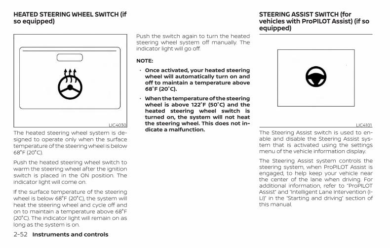
The heated steering wheel system is de-signed to operate only when the surfacetemperature of the steering wheel is below68°F (20°C).
Push the heated steering wheel switch towarm the steering wheel after the ignitionswitch is placed in the ON position. Theindicator light will come on.
If the surface temperature of the steeringwheel is below 68°F (20°C), the system willheat the steering wheel and cycle off andon to maintain a temperature above 68°F(20°C). The indicator light will remain on aslong as the system is on.
Push the switch again to turn the heatedsteering wheel system off manually. Theindicator light will go off.
NOTE:
∙ Once activated, your heated steeringwheel will automatically turn on andoff to maintain a temperature above68°F (20°C).
∙ When the temperature of the steeringwheel is above 122°F (50°C) and theheated steering wheel switch isturned on, the system will not heatthe steering wheel. This does not in-dicate a malfunction. The Steering Assist switch is used to en-
able and disable the Steering Assist sys-tem that is activated using the settingsmenu of the vehicle information display.
The Steering Assist system controls thesteering system, when ProPILOT Assist isengaged, to help keep your vehicle nearthe center of the lane when driving. Foradditional information, refer to ”ProPILOTAssist” and “Intelligent Lane Intervention (I-LI)” in the “Starting and driving” section ofthis manual.
LIC4030 LIC4101
HEATED STEERING WHEEL SWITCH (ifso equipped)
STEERING ASSIST SWITCH (forvehicles with ProPILOT Assist) (if soequipped)
2-52 Instruments and controls
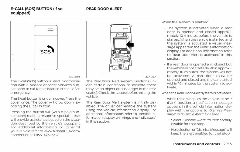
The E-call (SOS) button is used in combina-tion with a NissanConnect® Services sub-scription to call for assistance in case of anemergency.
The E-call button is under a cover. Press thecover once. The cover will drop down, ex-posing the E-call button.
Pressing the button will (with a paid sub-scription) reach a response specialist thatwill provide assistance based on the situa-tion described by the vehicle’s occupant.For additional information, or to enrollyour vehicle, refer to www.NissanUSA.com/connect or call 855–426–6628.
The Rear Door Alert system functions un-der certain conditions to indicate theremay be an object or passenger in the rearseat(s). Check the seat(s) before exiting thevehicle.
The Rear Door Alert system is initially dis-abled. The driver can enable the systemusing the vehicle information display. Foradditional information, refer to “Vehicle in-formation display warnings and indicators”in this section.
When the system is enabled:
∙ The system is activated when a reardoor is opened and closed approxi-mately 10 minutes before the vehicle isstarted. When the vehicle is started andthe system is activated, a visual mes-sage appears in the vehicle informationdisplay. For additional information, referto “Rear Door Alert is activated” in thissection.
∙ If a rear door is opened and closed butthe vehicle is not started within approxi-mately 10 minutes, the system will notbe activated. A rear door must beopened and closed and the car startedwithin 10 minutes for the system to ac-tivate.
When the Rear Door Alert system is activated:
∙ When the driver puts the vehicle in the P(Park) position, a notification messageappears in the vehicle information dis-play with the options to “Dismiss Mes-sage” or “Disable Alert” if desired.
∙ Select “Disable Alert” to temporarilydisable for that stop.
∙ No selection or ‘Dismiss Message” willkeep the alert enabled for that stop.
LIC4036 LIC4069
E-CALL (SOS) BUTTON (if soequipped)
REAR DOOR ALERT
Instruments and controls 2-53
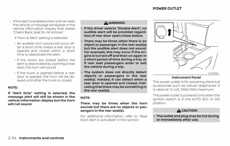
∙ If the alert is enabled when a driver exitsthe vehicle, a message will appear in thevehicle information display that states“Check Back Seat for All Articles.”
If “Horn & Alert” setting is selected:
∙ An audible horn sound will occur af-ter a short time unless a rear door isopened and closed within a shorttime to deactivate the alert.
∙ If the doors are locked before thealert is deactivated by opening a reardoor, the horn will sound.
∙ If the trunk is opened before a reardoor is opened, the horn will be de-layed until after the trunk is closed.
NOTE:
If “Alert Only” setting is selected, themessage alert will still be shown in thevehicle information display but the hornwill not sound.
WARNING∙ If the driver selects “Disable Alert”, no
audible alert will be provided regard-less of rear door open/close status.
∙ There may be times when there is anobject or passenger in the rear seat(s)but the audible alert does not sound.For example, this may occur if the en-gine is turned off and then on again ina short period of time during a trip, orif rear seat passengers enter or exitthe vehicle during a trip.
∙ The system does not directly detectobjects or passengers in the rearseat(s). Instead, it can detect when arear door is opened and closed, indi-cating that there may be something inthe rear seat(s).
NOTE:
There may be times when the hornsounds but there are no objects or pas-sengers in the rear seat(s).
For additional information, refer to “RearDoor Alert is activated” in this section.
The power outlet is for powering electricalaccessories such as cellular telephones. Itis rated at 12 volt, 120W (10A) maximum.
The power outlet is powered only when theignition switch is in the AUTO ACC or ONposition.
CAUTION∙ The outlet and plug may be hot during
or immediately after use.
Instrument PanelLIC3345
POWER OUTLET
2-54 Instruments and controls
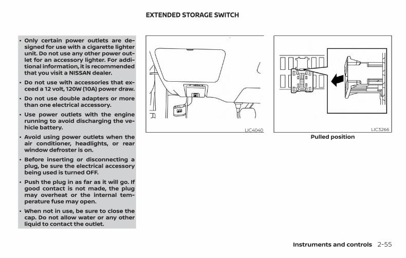
∙ Only certain power outlets are de-signed for use with a cigarette lighterunit. Do not use any other power out-let for an accessory lighter. For addi-tional information, it is recommendedthat you visit a NISSAN dealer.
∙ Do not use with accessories that ex-ceed a 12 volt, 120W (10A) power draw.
∙ Do not use double adapters or morethan one electrical accessory.
∙ Use power outlets with the enginerunning to avoid discharging the ve-hicle battery.
∙ Avoid using power outlets when theair conditioner, headlights, or rearwindow defroster is on.
∙ Before inserting or disconnecting aplug, be sure the electrical accessorybeing used is turned OFF.
∙ Push the plug in as far as it will go. Ifgood contact is not made, the plugmay overheat or the internal tem-perature fuse may open.
∙ When not in use, be sure to close thecap. Do not allow water or any otherliquid to contact the outlet.
LIC4040Pulled position
LIC3266
EXTENDED STORAGE SWITCH
Instruments and controls 2-55
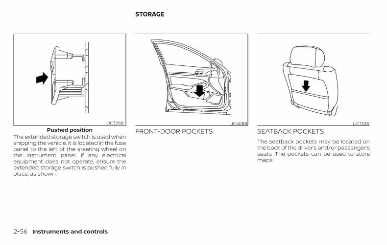
The extended storage switch is used whenshipping the vehicle. It is located in the fusepanel to the left of the steering wheel onthe instrument panel. If any electricalequipment does not operate, ensure theextended storage switch is pushed fully inplace, as shown.
FRONT-DOOR POCKETS SEATBACK POCKETSThe seatback pockets may be located onthe back of the driver’s and/or passenger’sseats. The pockets can be used to storemaps.
Pushed positionLIC3268 LIC4088 LIC1328
STORAGE
2-56 Instruments and controls
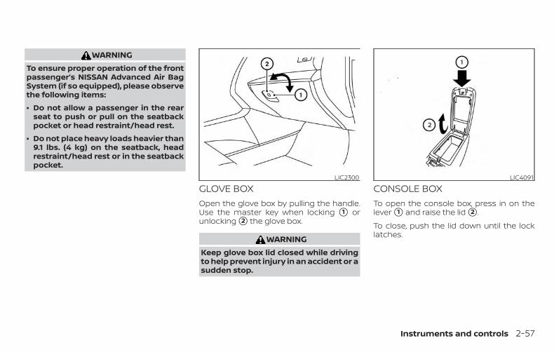
WARNINGTo ensure proper operation of the frontpassenger’s NISSAN Advanced Air BagSystem (if so equipped), please observethe following items:
∙ Do not allow a passenger in the rearseat to push or pull on the seatbackpocket or head restraint/head rest.
∙ Do not place heavy loads heavier than9.1 lbs. (4 kg) on the seatback, headrestraint/head rest or in the seatbackpocket.
GLOVE BOXOpen the glove box by pulling the handle.Use the master key when locking �1 orunlocking �2 the glove box.
WARNINGKeep glove box lid closed while drivingto help prevent injury in an accident or asudden stop.
CONSOLE BOXTo open the console box, press in on thelever �1 and raise the lid �2 .
To close, push the lid down until the locklatches.
LIC2300 LIC4091
Instruments and controls 2-57
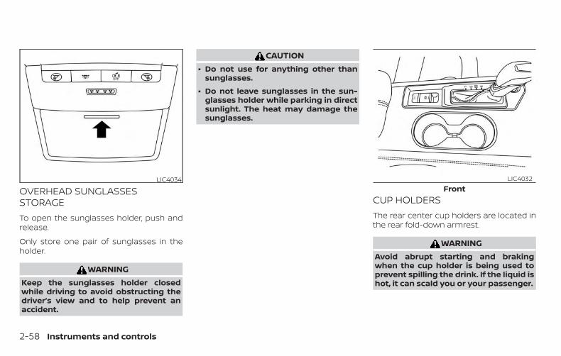
OVERHEAD SUNGLASSESSTORAGETo open the sunglasses holder, push andrelease.
Only store one pair of sunglasses in theholder.
WARNINGKeep the sunglasses holder closedwhile driving to avoid obstructing thedriver’s view and to help prevent anaccident.
CAUTION∙ Do not use for anything other than
sunglasses.
∙ Do not leave sunglasses in the sun-glasses holder while parking in directsunlight. The heat may damage thesunglasses.
CUP HOLDERSThe rear center cup holders are located inthe rear fold-down armrest.
WARNINGAvoid abrupt starting and brakingwhen the cup holder is being used toprevent spilling the drink. If the liquid ishot, it can scald you or your passenger.
LIC4034Front
LIC4032
2-58 Instruments and controls
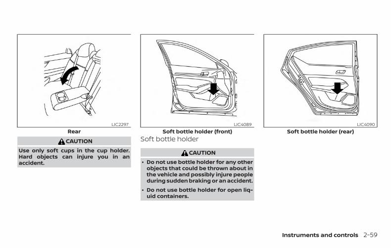
CAUTIONUse only soft cups in the cup holder.Hard objects can injure you in anaccident.
Soft bottle holder
CAUTION∙ Do not use bottle holder for any other
objects that could be thrown about inthe vehicle and possibly injure peopleduring sudden braking or an accident.
∙ Do not use bottle holder for open liq-uid containers.
RearLIC2297
Soft bottle holder (front)LIC4089
Soft bottle holder (rear)LIC4090
Instruments and controls 2-59
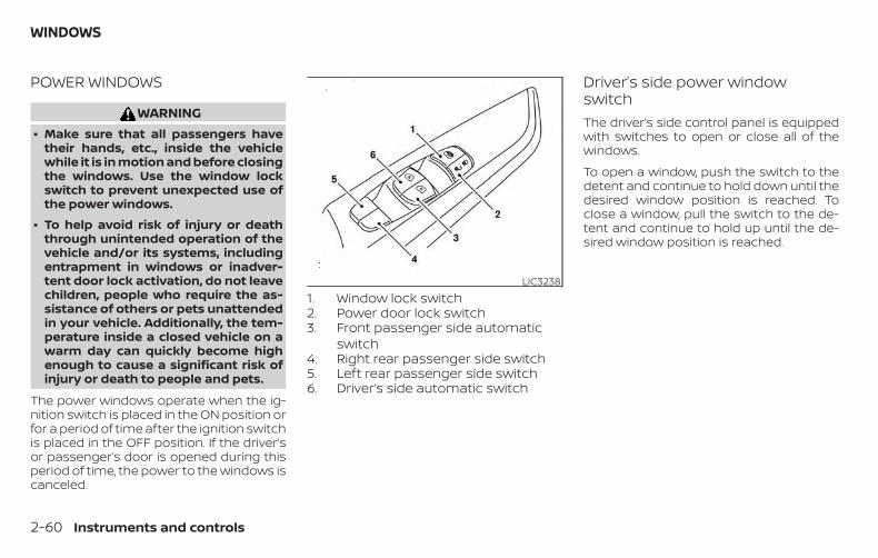
POWER WINDOWS
WARNING∙ Make sure that all passengers have
their hands, etc., inside the vehiclewhile it is in motion and before closingthe windows. Use the window lockswitch to prevent unexpected use ofthe power windows.
∙ To help avoid risk of injury or deaththrough unintended operation of thevehicle and/or its systems, includingentrapment in windows or inadver-tent door lock activation, do not leavechildren, people who require the as-sistance of others or pets unattendedin your vehicle. Additionally, the tem-perature inside a closed vehicle on awarm day can quickly become highenough to cause a significant risk ofinjury or death to people and pets.
The power windows operate when the ig-nition switch is placed in the ON position orfor a period of time after the ignition switchis placed in the OFF position. If the driver’sor passenger’s door is opened during thisperiod of time, the power to the windows iscanceled.
1. Window lock switch2. Power door lock switch3. Front passenger side automatic
switch4. Right rear passenger side switch5. Left rear passenger side switch6. Driver’s side automatic switch
Driver’s side power windowswitchThe driver’s side control panel is equippedwith switches to open or close all of thewindows.
To open a window, push the switch to thedetent and continue to hold down until thedesired window position is reached. Toclose a window, pull the switch to the de-tent and continue to hold up until the de-sired window position is reached.
LIC3238
WINDOWS
2-60 Instruments and controls
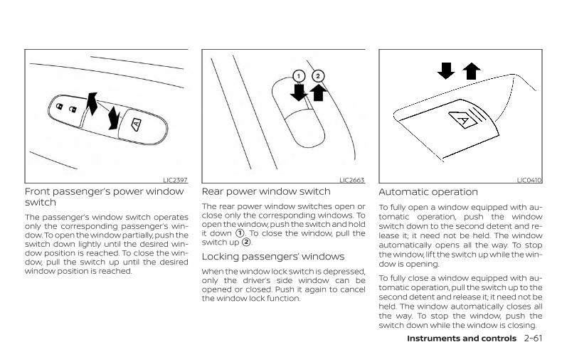
Front passenger’s power windowswitchThe passenger’s window switch operatesonly the corresponding passenger’s win-dow. To open the window partially, push theswitch down lightly until the desired win-dow position is reached. To close the win-dow, pull the switch up until the desiredwindow position is reached.
Rear power window switchThe rear power window switches open orclose only the corresponding windows. Toopen the window, push the switch and holdit down �1 . To close the window, pull theswitch up �2 .
Locking passengers’ windowsWhen the window lock switch is depressed,only the driver’s side window can beopened or closed. Push it again to cancelthe window lock function.
Automatic operationTo fully open a window equipped with au-tomatic operation, push the windowswitch down to the second detent and re-lease it; it need not be held. The windowautomatically opens all the way. To stopthe window, lift the switch up while the win-dow is opening.
To fully close a window equipped with au-tomatic operation, pull the switch up to thesecond detent and release it; it need not beheld. The window automatically closes allthe way. To stop the window, push theswitch down while the window is closing.
LIC2397 LIC2663 LIC0410
Instruments and controls 2-61
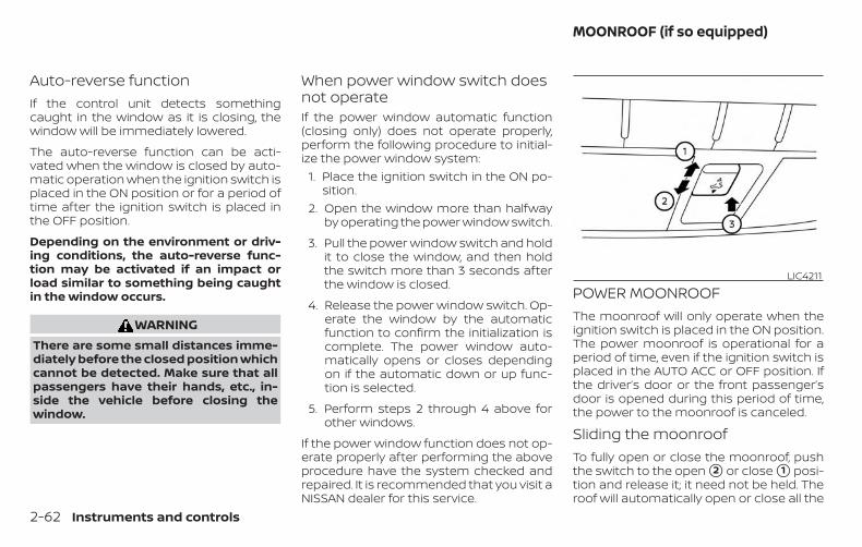
Auto-reverse functionIf the control unit detects somethingcaught in the window as it is closing, thewindow will be immediately lowered.
The auto-reverse function can be acti-vated when the window is closed by auto-matic operation when the ignition switch isplaced in the ON position or for a period oftime after the ignition switch is placed inthe OFF position.
Depending on the environment or driv-ing conditions, the auto-reverse func-tion may be activated if an impact orload similar to something being caughtin the window occurs.
WARNINGThere are some small distances imme-diately before the closed position whichcannot be detected. Make sure that allpassengers have their hands, etc., in-side the vehicle before closing thewindow.
When power window switch doesnot operateIf the power window automatic function(closing only) does not operate properly,perform the following procedure to initial-ize the power window system:
1. Place the ignition switch in the ON po-sition.
2. Open the window more than halfwayby operating the power window switch.
3. Pull the power window switch and holdit to close the window, and then holdthe switch more than 3 seconds afterthe window is closed.
4. Release the power window switch. Op-erate the window by the automaticfunction to confirm the initialization iscomplete. The power window auto-matically opens or closes dependingon if the automatic down or up func-tion is selected.
5. Perform steps 2 through 4 above forother windows.
If the power window function does not op-erate properly after performing the aboveprocedure have the system checked andrepaired. It is recommended that you visit aNISSAN dealer for this service.
POWER MOONROOFThe moonroof will only operate when theignition switch is placed in the ON position.The power moonroof is operational for aperiod of time, even if the ignition switch isplaced in the AUTO ACC or OFF position. Ifthe driver’s door or the front passenger’sdoor is opened during this period of time,the power to the moonroof is canceled.
Sliding the moonroofTo fully open or close the moonroof, pushthe switch to the open �2 or close �1 posi-tion and release it; it need not be held. Theroof will automatically open or close all the
LIC4211
MOONROOF (if so equipped)
2-62 Instruments and controls
way. To stop the roof, push the switch oncemore while it is opening or closing.
Tilting the moonroofTo tilt up, first close the moonroof, thenpush the switch �3 and release it; it neednot be held. To tilt down the moonroof,push the switch to the tilt down position �1 .
Resetting the moonroof switchIf the moonroof does not operate properly,perform the following procedure to initial-ize the moonroof operation system.
1. If the moonroof is open, close it fully byrepeatedly pushing the moonroofswitch to the close position �1 to tilt themoonroof up.
2. Push and hold the switch to the closeposition �1 .
3. Release the moonroof switch after themoonroof moves slightly up and down.
4. Push and hold the switch to the openposition �2 to fully tilt the moonroofdown.
5. Check if the moonroof switch operatesnormally.
If the moonroof does not operate properlyafter performing the procedure above,have your vehicle serviced. It is recom-mended that you visit a NISSAN dealer forthis service.
Auto-reverse function (whenclosing or tilting down themoonroof)The auto-reverse function can be acti-vated when the moonroof is closed ortilted down by automatic operation whenthe ignition switch is placed in the ON po-sition or for a period of time after the igni-tion switch is placed in the OFF position.
Depending on the environment or driv-ing conditions, the auto-reverse func-tion may be activated if an impact orload similar to something being caughtin the moonroof occurs.
WARNINGThere are some small distances imme-diately before the closed position whichcannot be detected. Make sure that allpassengers have their hands, etc., in-side the vehicle before closing themoonroof.
When closing
If the control unit detects somethingcaught in the moonroof as it moves to thefront, the moonroof will immediately openbackward.
When tilting down
If the control unit detects somethingcaught in the moonroof as it tilts down, themoonroof will immediately tilt up.
If the auto-reverse function malfunctionsand repeats opening or tilting up themoonroof, keep pushing the tilt downswitch within 5 seconds after it happens;the moonroof will fully close gradually.Make sure nothing is caught in the moon-roof.
WARNING∙ In an accident you could be thrown
from the vehicle through an openmoonroof. Always use seat belts andchild restraints.
∙ Do not allow anyone to stand up orextend any portion of their body outof the moonroof opening while thevehicle is in motion or while themoonroof is closing.
Instruments and controls 2-63
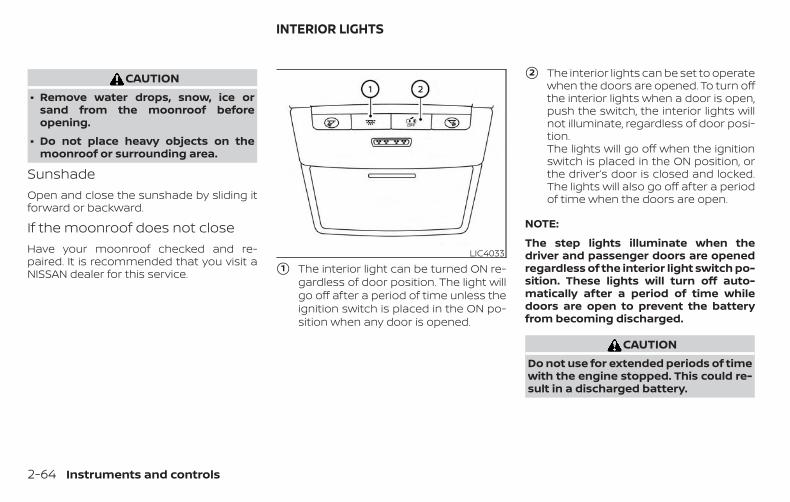
CAUTION∙ Remove water drops, snow, ice or
sand from the moonroof beforeopening.
∙ Do not place heavy objects on themoonroof or surrounding area.
SunshadeOpen and close the sunshade by sliding itforward or backward.
If the moonroof does not closeHave your moonroof checked and re-paired. It is recommended that you visit aNISSAN dealer for this service. �1 The interior light can be turned ON re-
gardless of door position. The light willgo off after a period of time unless theignition switch is placed in the ON po-sition when any door is opened.
�2 The interior lights can be set to operatewhen the doors are opened. To turn offthe interior lights when a door is open,push the switch, the interior lights willnot illuminate, regardless of door posi-tion.The lights will go off when the ignitionswitch is placed in the ON position, orthe driver’s door is closed and locked.The lights will also go off after a periodof time when the doors are open.
NOTE:
The step lights illuminate when thedriver and passenger doors are openedregardless of the interior light switch po-sition. These lights will turn off auto-matically after a period of time whiledoors are open to prevent the batteryfrom becoming discharged.
CAUTIONDo not use for extended periods of timewith the engine stopped. This could re-sult in a discharged battery.
LIC4033
INTERIOR LIGHTS
2-64 Instruments and controls
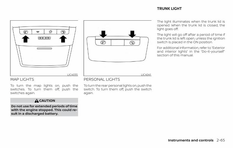
MAP LIGHTSTo turn the map lights on, push theswitches. To turn them off, push theswitches again.
CAUTIONDo not use for extended periods of timewith the engine stopped. This could re-sult in a discharged battery.
PERSONAL LIGHTSTo turn the rear personal lights on, push theswitch. To turn them off, push the switchagain.
The light illuminates when the trunk lid isopened. When the trunk lid is closed, thelight goes off.
The light will go off after a period of time ifthe trunk lid is left open, unless the ignitionswitch is placed in the ON position.
For additional information, refer to “Exteriorand interior lights” in the “Do-it-yourself ”section of this manual.
LIC4035 LIC4041
TRUNK LIGHT
Instruments and controls 2-65
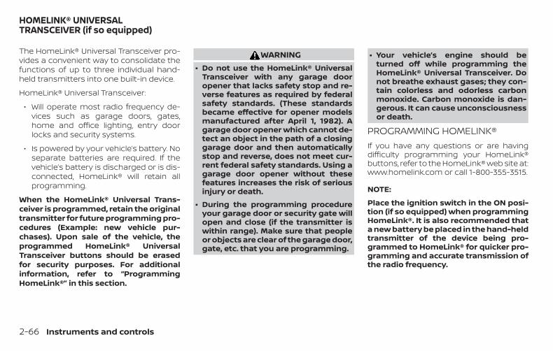
The HomeLink® Universal Transceiver pro-vides a convenient way to consolidate thefunctions of up to three individual hand-held transmitters into one built-in device.
HomeLink® Universal Transceiver:
∙ Will operate most radio frequency de-vices such as garage doors, gates,home and office lighting, entry doorlocks and security systems.
∙ Is powered by your vehicle’s battery. Noseparate batteries are required. If thevehicle’s battery is discharged or is dis-connected, HomeLink® will retain allprogramming.
When the HomeLink® Universal Trans-ceiver is programmed, retain the originaltransmitter for future programming pro-cedures (Example: new vehicle pur-chases). Upon sale of the vehicle, theprogrammed HomeLink® UniversalTransceiver buttons should be erasedfor security purposes. For additionalinformation, refer to “ProgrammingHomeLink®” in this section.
WARNING∙ Do not use the HomeLink® Universal
Transceiver with any garage dooropener that lacks safety stop and re-verse features as required by federalsafety standards. (These standardsbecame effective for opener modelsmanufactured after April 1, 1982). Agarage door opener which cannot de-tect an object in the path of a closinggarage door and then automaticallystop and reverse, does not meet cur-rent federal safety standards. Using agarage door opener without thesefeatures increases the risk of seriousinjury or death.
∙ During the programming procedureyour garage door or security gate willopen and close (if the transmitter iswithin range). Make sure that peopleor objects are clear of the garage door,gate, etc. that you are programming.
∙ Your vehicle’s engine should beturned off while programming theHomeLink® Universal Transceiver. Donot breathe exhaust gases; they con-tain colorless and odorless carbonmonoxide. Carbon monoxide is dan-gerous. It can cause unconsciousnessor death.
PROGRAMMING HOMELINK®If you have any questions or are havingdifficulty programming your HomeLink®buttons, refer to the HomeLink® web site at:www.homelink.com or call 1-800-355-3515.
NOTE:
Place the ignition switch in the ON posi-tion (if so equipped) when programmingHomeLink®. It is also recommended thata new battery be placed in the hand-heldtransmitter of the device being pro-grammed to HomeLink® for quicker pro-gramming and accurate transmission ofthe radio frequency.
HOMELINK® UNIVERSALTRANSCEIVER (if so equipped)
2-66 Instruments and controls
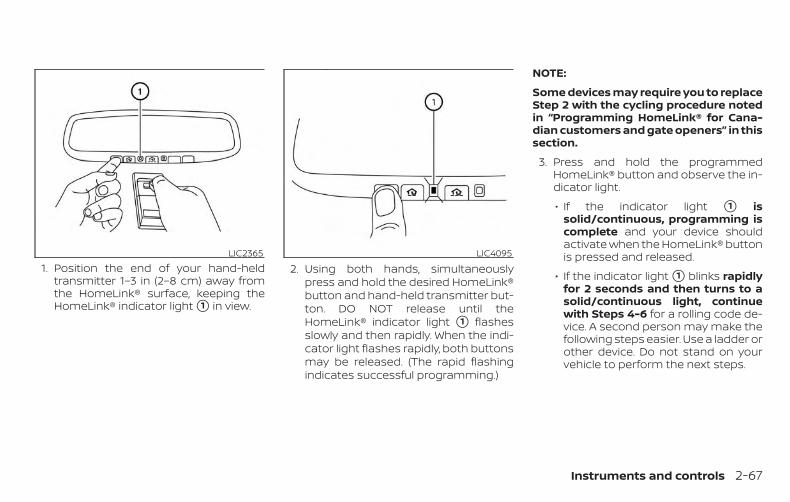
1. Position the end of your hand-heldtransmitter 1–3 in (2–8 cm) away fromthe HomeLink® surface, keeping theHomeLink® indicator light �1 in view.
2. Using both hands, simultaneouslypress and hold the desired HomeLink®button and hand-held transmitter but-ton. DO NOT release until theHomeLink® indicator light �1 flashesslowly and then rapidly. When the indi-cator light flashes rapidly, both buttonsmay be released. (The rapid flashingindicates successful programming.)
NOTE:
Some devices may require you to replaceStep 2 with the cycling procedure notedin “Programming HomeLink® for Cana-dian customers and gate openers” in thissection.
3. Press and hold the programmedHomeLink® button and observe the in-dicator light.
∙ If the indicator light �1 issolid/continuous, programming iscomplete and your device shouldactivate when the HomeLink® buttonis pressed and released.
∙ If the indicator light �1 blinks rapidlyfor 2 seconds and then turns to asolid/continuous light, continuewith Steps 4-6 for a rolling code de-vice. A second person may make thefollowing steps easier. Use a ladder orother device. Do not stand on yourvehicle to perform the next steps.
LIC2365 LIC4095
Instruments and controls 2-67
4. At the receiver located on the garagedoor opener motor in the garage, lo-cate the “learn” or “smart” button (thename and color of the button may varyby manufacturer but it is usually lo-cated near where the hanging an-tenna wire is attached to the unit). Ifthere is difficulty locating the button,reference the garage door opener’smanual.
5. Press and release the “learn” or “smart”button.
6. Return to the vehicle and firmly pressand hold the trained HomeLink® but-ton for 2 seconds and release. Repeatthe “press/hold/release” sequence upto three times to complete the trainingprocess. HomeLink® should now acti-vate your rolling code equipped device.
7. If you have any questions or are havingdifficulty programming your HomeLink®buttons, refer to the HomeLink® web siteat: www.homelink.com or call 1-800-355-3515.
PROGRAMMING HOMELINK® FORCANADIAN CUSTOMERS AND GATEOPENERSCanadian radio-frequency laws requiretransmitter signals to “time-out” (or quit)after several seconds of transmission –which may not be long enough forHomeLink® to pick up the signal duringtraining. Similar to this Canadian law, someU.S. gate operators are designed to “tim-eout” in the same manner.
If you live in Canada or you are having diffi-culties training a gate operator or garagedoor opener by using the “Training” proce-dures, replace “Programming HomeLink®”step 2 with the following:
NOTE:
When programming a garage dooropener, etc., unplug the device duringthe “cycling” process to prevent possibledamage to the garage door opener com-ponents.
1. For additional information, refer to “Pro-gramming HomeLink®” step 1 in thissection.
2. Using both hands, simultaneouslypress and hold the desired HomeLink®button and the hand-held transmitterbutton. During training, your hand-heldtransmitter may automatically stoptransmitting. Continue to press andhold the desired HomeLink® buttonwhile you press and re-press (“cycle”)your hand-held transmitter every2 seconds until the frequency signalhas been learned. The HomeLink® indi-cator light will flash slowly and thenrapidly after several seconds uponsuccessful training. DO NOT release un-til the HomeLink® indicator light flashesslowly and then rapidly. When the indi-cator light flashes rapidly, both buttonsmay be released. The rapid flashing in-dicates successful training.Proceed with “Programming HomeLink®”step 3 to complete.If the device was unplugged during theprogramming procedure, remember toplug it back in when programming iscompleted.
2-68 Instruments and controls
OPERATING THE HOMELINK®UNIVERSAL TRANSCEIVERThe HomeLink® Universal Transceiver, afterit is programmed, can be used to activatethe programmed device. To operate, sim-ply press and release the appropriate pro-grammed HomeLink® Universal Trans-ceiver button. The amber indicator light willilluminate while the signal is being trans-mitted.
For convenience, the hand-held transmit-ter of the device may also be used at anytime.
PROGRAMMING TROUBLE-DIAGNOSISIf the HomeLink® does not quickly learn thehand-held transmitter information:
∙ Replace the hand-held transmitter bat-teries with new batteries.
∙ Position the hand-held transmitter withits battery area facing away from theHomeLink® surface.
∙ Press and hold both the HomeLink®and hand-held transmitter buttonswithout interruption.
∙ Position the hand-held transmitter 1 -3 inches (26 - 76 mm) away from theHomeLink® surface. Hold the transmit-ter in that position for up to 15 seconds.If HomeLink® is not programmed withinthat time, try holding the transmitter inanother position – keeping the indicatorlight in view at all times.
If you have any questions or are havingdifficulty programming your HomeLink®buttons, refer to the HomeLink® web site at:www.homelink.com or call 1-800-355-3515.
CLEARING THE PROGRAMMEDINFORMATIONThe following procedure clears the pro-grammed information from both buttons.Individual buttons cannot be cleared. How-ever, individual buttons can be repro-grammed. For additional information, referto “Reprogramming a single HomeLink®button” in this section.
To clear all programming:
1. Press and hold the two outerHomeLink® buttons until the indicatorlight begins to flash in approximately10 seconds. Do not hold for longer than20 seconds.
2. Release both buttons.
HomeLink® is now in the programmingmode and can be programmed at anytime beginning with “ProgrammingHomeLink®” - Step 1.
REPROGRAMMING A SINGLEHOMELINK® BUTTONTo reprogram a HomeLink® UniversalTransceiver button, complete the following:
1. Press and hold the desired HomeLink®button. DO NOT release the button.
2. The indicator light will begin to flashafter 20 seconds. Without releasing theHomeLink® button, proceed with “Pro-gramming HomeLink®” - Step 1.
For questions or comments, contactHomeLink® at: www.homelink.com or1–800–355–3515 (except Mexico).
The HomeLink® Universal Transceiver but-ton has now been reprogrammed. Thenew device can be activated by pressingthe HomeLink® button that was just pro-grammed. This procedure will not affectany other programmed HomeLink® but-tons.
Instruments and controls 2-69
IF YOUR VEHICLE IS STOLENIf your vehicle is stolen, you should changethe codes of any non-rolling code devicethat has been programmed intoHomeLink®. Consult the Owner’s Manual ofeach device or call the manufacturer ordealer of those devices for additional infor-mation.
When your vehicle is recovered, you willneed to reprogram the HomeLink® Uni-versal Transceiver with your new trans-mitter information.
FCC Notice:
For USA:
This device complies with Part 15 of theFCC Rules. Operation is subject to the fol-lowing two conditions: (1) This devicemay not cause interference, and (2) thisdevice must accept any interference re-ceived, including interference that maycause undesired operation.
NOTE:
Changes or modifications not expresslyapproved by the party responsible forcompliance could void the user’s author-ity to operate the equipment.
For Canada:
This device complies with IndustryCanada licence-exempt RSS standard(s).Operation is subject to the following twoconditions: (1) this device may not causeinterference, and (2) this device must ac-cept any interference, including interfer-ence that may cause undesired opera-tion of the device.
2-70 Instruments and controls

MEMO
Instruments and controls 2-71
3 Pre-driving checks and adjustments
Keys . . . . . . . . . . . . . . . . . . . . . . . . . . . . . . . . . . . . . . . . . . . . . 3-2NISSAN Intelligent Key® . . . . . . . . . . . . . . . . . . . . . . . 3-2NISSAN Vehicle Immobilizer Systemkeys . . . . . . . . . . . . . . . . . . . . . . . . . . . . . . . . . . . . . . . . . . 3-4
Doors . . . . . . . . . . . . . . . . . . . . . . . . . . . . . . . . . . . . . . . . . . . 3-4Locking with key. . . . . . . . . . . . . . . . . . . . . . . . . . . . . . 3-5Locking with inside lock knob. . . . . . . . . . . . . . . . . 3-6Locking with power door lock switch . . . . . . . . . 3-6Automatic door locks (if so equipped) . . . . . . . . 3-7Child safety rear door lock . . . . . . . . . . . . . . . . . . . . 3-7
NISSAN Intelligent Key® . . . . . . . . . . . . . . . . . . . . . . . . . . 3-7Operating range. . . . . . . . . . . . . . . . . . . . . . . . . . . . . . 3-9Door locks/unlocks precaution . . . . . . . . . . . . . . 3-10NISSAN Intelligent Key® operation. . . . . . . . . . . . 3-10How to use the remote keyless entryfunction . . . . . . . . . . . . . . . . . . . . . . . . . . . . . . . . . . . . . 3-14Warning signals . . . . . . . . . . . . . . . . . . . . . . . . . . . . . 3-18Troubleshooting guide . . . . . . . . . . . . . . . . . . . . . . 3-18
Remote Engine Start . . . . . . . . . . . . . . . . . . . . . . . . . . . 3-21Remote Engine Start operating range . . . . . . . 3-21Remote starting the vehicle . . . . . . . . . . . . . . . . . 3-22Extending engine run time . . . . . . . . . . . . . . . . . . 3-22
Canceling a Remote Engine Start . . . . . . . . . . . . 3-22Conditions the Remote Engine Start willnot work . . . . . . . . . . . . . . . . . . . . . . . . . . . . . . . . . . . . 3-23
Hood . . . . . . . . . . . . . . . . . . . . . . . . . . . . . . . . . . . . . . . . . . . 3-24Trunk lid . . . . . . . . . . . . . . . . . . . . . . . . . . . . . . . . . . . . . . . . 3-25
Opener operation . . . . . . . . . . . . . . . . . . . . . . . . . . . 3-25Interior trunk lid release . . . . . . . . . . . . . . . . . . . . . 3-26Interior trunk access . . . . . . . . . . . . . . . . . . . . . . . . 3-26
Fuel-filler door . . . . . . . . . . . . . . . . . . . . . . . . . . . . . . . . . . 3-27Opener operation . . . . . . . . . . . . . . . . . . . . . . . . . . . 3-27Fuel-filler cap . . . . . . . . . . . . . . . . . . . . . . . . . . . . . . . . 3-27
Steering wheel . . . . . . . . . . . . . . . . . . . . . . . . . . . . . . . . . 3-29Tilt operation . . . . . . . . . . . . . . . . . . . . . . . . . . . . . . . . 3-30Telescopic operation . . . . . . . . . . . . . . . . . . . . . . . . 3-30
Sun visors . . . . . . . . . . . . . . . . . . . . . . . . . . . . . . . . . . . . . . 3-30Vanity mirrors . . . . . . . . . . . . . . . . . . . . . . . . . . . . . . . 3-31
Mirrors . . . . . . . . . . . . . . . . . . . . . . . . . . . . . . . . . . . . . . . . . 3-31Manual anti-glare rearview mirror(if so equipped) . . . . . . . . . . . . . . . . . . . . . . . . . . . . . . 3-31Automatic anti-glare rearview mirror(if so equipped) . . . . . . . . . . . . . . . . . . . . . . . . . . . . . . 3-32Outside mirrors . . . . . . . . . . . . . . . . . . . . . . . . . . . . . 3-32
Automatic drive positioner (if so equipped) . . . . . 3-33Memory storage function (key-link) . . . . . . . . . . 3-34Memory storage function (switch) . . . . . . . . . . . 3-34
Entry/exit function . . . . . . . . . . . . . . . . . . . . . . . . . . 3-35System operation . . . . . . . . . . . . . . . . . . . . . . . . . . . 3-35
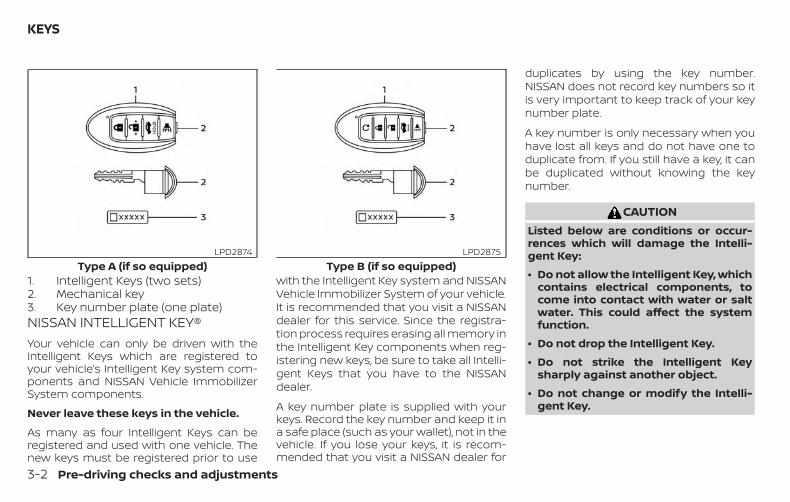
1. Intelligent Keys (two sets)2. Mechanical key3. Key number plate (one plate)NISSAN INTELLIGENT KEY®Your vehicle can only be driven with theIntelligent Keys which are registered toyour vehicle’s Intelligent Key system com-ponents and NISSAN Vehicle ImmobilizerSystem components.
Never leave these keys in the vehicle.
As many as four Intelligent Keys can beregistered and used with one vehicle. Thenew keys must be registered prior to use
with the Intelligent Key system and NISSANVehicle Immobilizer System of your vehicle.It is recommended that you visit a NISSANdealer for this service. Since the registra-tion process requires erasing all memory inthe Intelligent Key components when reg-istering new keys, be sure to take all Intelli-gent Keys that you have to the NISSANdealer.
A key number plate is supplied with yourkeys. Record the key number and keep it ina safe place (such as your wallet), not in thevehicle. If you lose your keys, it is recom-mended that you visit a NISSAN dealer for
duplicates by using the key number.NISSAN does not record key numbers so itis very important to keep track of your keynumber plate.
A key number is only necessary when youhave lost all keys and do not have one toduplicate from. If you still have a key, it canbe duplicated without knowing the keynumber.
CAUTIONListed below are conditions or occur-rences which will damage the Intelli-gent Key:
∙ Do not allow the Intelligent Key, whichcontains electrical components, tocome into contact with water or saltwater. This could affect the systemfunction.
∙ Do not drop the Intelligent Key.
∙ Do not strike the Intelligent Keysharply against another object.
∙ Do not change or modify the Intelli-gent Key.
Type A (if so equipped)LPD2874
Type B (if so equipped)LPD2875
KEYS
3-2 Pre-driving checks and adjustments
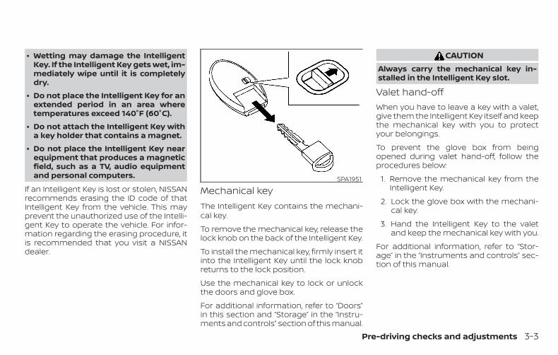
∙ Wetting may damage the IntelligentKey. If the Intelligent Key gets wet, im-mediately wipe until it is completelydry.
∙ Do not place the Intelligent Key for anextended period in an area wheretemperatures exceed 140°F (60°C).
∙ Do not attach the Intelligent Key witha key holder that contains a magnet.
∙ Do not place the Intelligent Key nearequipment that produces a magneticfield, such as a TV, audio equipmentand personal computers.
If an Intelligent Key is lost or stolen, NISSANrecommends erasing the ID code of thatIntelligent Key from the vehicle. This mayprevent the unauthorized use of the Intelli-gent Key to operate the vehicle. For infor-mation regarding the erasing procedure, itis recommended that you visit a NISSANdealer.
Mechanical keyThe Intelligent Key contains the mechani-cal key.
To remove the mechanical key, release thelock knob on the back of the Intelligent Key.
To install the mechanical key, firmly insert itinto the Intelligent Key until the lock knobreturns to the lock position.
Use the mechanical key to lock or unlockthe doors and glove box.
For additional information, refer to “Doors”in this section and “Storage” in the “Instru-ments and controls” section of this manual.
CAUTIONAlways carry the mechanical key in-stalled in the Intelligent Key slot.
Valet hand-offWhen you have to leave a key with a valet,give them the Intelligent Key itself and keepthe mechanical key with you to protectyour belongings.
To prevent the glove box from beingopened during valet hand-off, follow theprocedures below:
1. Remove the mechanical key from theIntelligent Key.
2. Lock the glove box with the mechani-cal key.
3. Hand the Intelligent Key to the valetand keep the mechanical key with you.
For additional information, refer to “Stor-age” in the “Instruments and controls” sec-tion of this manual.
SPA1951
Pre-driving checks and adjustments 3-3
NISSAN VEHICLE IMMOBILIZERSYSTEM KEYSYou can only drive your vehicle using theIntelligent Keys which are registered to theNISSAN Vehicle Immobilizer System com-ponents in your vehicle.
The mechanical key can be used for all thelocks.
Never leave the keys in the vehicle.
Additional or replacement keys:
If you still have a key, the key number is notnecessary when you need extra NISSANVehicle Immobilizer System keys. Your ex-isting key can be duplicated without know-ing the key number. As many as fourNISSAN Vehicle Immobilizer System keyscan be used with one vehicle. You shouldbring all NISSAN Vehicle Immobilizer Sys-tem keys that you have to the NISSANdealer for registration. This is because theregistration process will erase the memoryof all key codes previously registered intothe NISSAN Vehicle Immobilizer System.After the registration process, these com-ponents will only recognize keys coded intothe NISSAN Vehicle Immobilizer System
during registration. Any key that is notgiven to the dealer at the time of registra-tion will no longer be able to start yourvehicle.
CAUTIONDo not allow the immobilizer systemkey, which contains an electrical tran-sponder, to come into contact withwater or salt water. This could affectsystem function.
When the doors are locked using one of thefollowing methods, the doors cannot beopened using the inside or outside doorhandles. The doors must be unlocked toopen the doors.
WARNING∙ Always have the doors locked while
driving. Along with the use of seatbelts, this provides greater safety inthe event of an accident by helping toprevent persons from being thrownfrom the vehicle. This also helps keepchildren and others from unintention-ally opening the doors, and will helpkeep out intruders.
∙ Before opening any door, always lookfor and avoid oncoming traffic.
DOORS
3-4 Pre-driving checks and adjustments
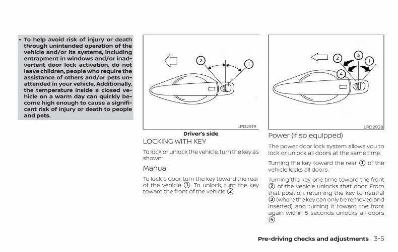
∙ To help avoid risk of injury or deaththrough unintended operation of thevehicle and/or its systems, includingentrapment in windows and/or inad-vertent door lock activation, do notleave children, people who require theassistance of others and/or pets un-attended in your vehicle. Additionally,the temperature inside a closed ve-hicle on a warm day can quickly be-come high enough to cause a signifi-cant risk of injury or death to peopleand pets.
LOCKING WITH KEYTo lock or unlock the vehicle, turn the key asshown.
ManualTo lock a door, turn the key toward the rearof the vehicle �1 . To unlock, turn the keytoward the front of the vehicle �2 .
Power (if so equipped)The power door lock system allows you tolock or unlock all doors at the same time.
Turning the key toward the rear �1 of thevehicle locks all doors.
Turning the key one time toward the front�2 of the vehicle unlocks that door. Fromthat position, returning the key to neutral�3 (where the key can only be removed andinserted) and turning it toward the frontagain within 5 seconds unlocks all doors�4 .
Driver’s sideLPD2919 LPD2928
Pre-driving checks and adjustments 3-5
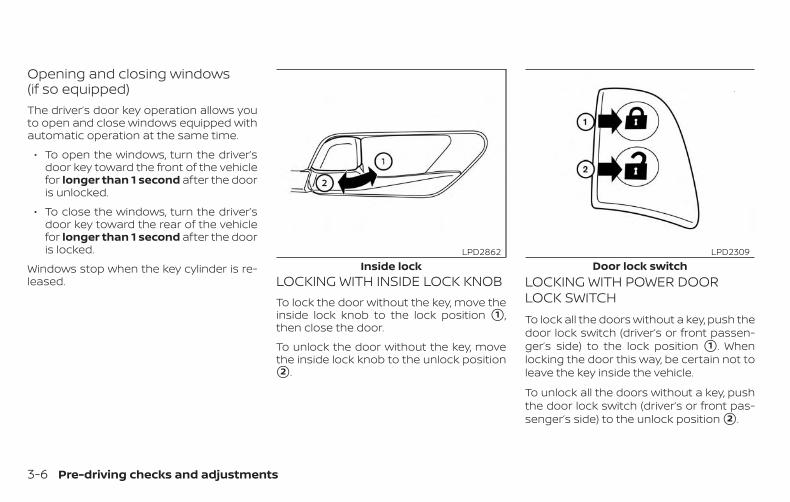
Opening and closing windows(if so equipped)The driver’s door key operation allows youto open and close windows equipped withautomatic operation at the same time.
∙ To open the windows, turn the driver’sdoor key toward the front of the vehiclefor longer than 1 second after the dooris unlocked.
∙ To close the windows, turn the driver’sdoor key toward the rear of the vehiclefor longer than 1 second after the dooris locked.
Windows stop when the key cylinder is re-leased. LOCKING WITH INSIDE LOCK KNOB
To lock the door without the key, move theinside lock knob to the lock position �1 ,then close the door.
To unlock the door without the key, movethe inside lock knob to the unlock position�2 .
LOCKING WITH POWER DOORLOCK SWITCHTo lock all the doors without a key, push thedoor lock switch (driver’s or front passen-ger’s side) to the lock position �1 . Whenlocking the door this way, be certain not toleave the key inside the vehicle.
To unlock all the doors without a key, pushthe door lock switch (driver’s or front pas-senger’s side) to the unlock position �2 .
Inside lockLPD2862
Door lock switchLPD2309
3-6 Pre-driving checks and adjustments
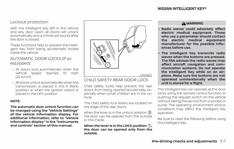
Lockout protectionWith the Intelligent Key left in the vehicleand any door open, all doors will unlockautomatically and a chime will sound afterthe door is closed.
These functions help to prevent the Intelli-gent Key from being accidentally lockedinside the vehicle.
AUTOMATIC DOOR LOCKS (if soequipped)
∙ All doors lock automatically when thevehicle speed reaches 15 mph(24 km/h).
∙ All doors unlock automatically when thetransmission is placed in the P (Park)position or when the ignition switch isplaced in the OFF position.
NOTE:
The automatic door unlock function canbe changed using the “Vehicle Settings”of the vehicle information display. Foradditional information, refer to “Vehicleinformation display” in the “Instrumentsand controls” section of this manual.
CHILD SAFETY REAR DOOR LOCKChild safety locks help prevent the reardoors from being opened accidentally, es-pecially when small children are in the ve-hicle.
The child safety lock levers are located onthe edge of the rear doors.
When the lever is in the unlock position �2 ,the door can be opened from the outsideor the inside.
When the lever is in the LOCK position �1 ,the door can be opened only from theoutside.
WARNING∙ Radio waves could adversely affect
electric medical equipment. Thosewho use a pacemaker should contactthe electric medical equipmentmanufacturer for the possible influ-ences before use.
∙ The Intelligent Key transmits radiowaves when the buttons are pressed.The FAA advises the radio waves mayaffect aircraft navigation and com-munication systems. Do not operatethe Intelligent Key while on an air-plane. Make sure the buttons are notoperated unintentionally when theunit is stored for a flight.
The Intelligent Key can operate all the doorlocks using the remote control function orpushing the request switch on the vehiclewithout taking the key out from a pocket orpurse. The operating environment and/orconditions may affect the Intelligent Keyoperation.
Be sure to read the following before usingthe Intelligent Key.
LPD2863
NISSAN INTELLIGENT KEY®
Pre-driving checks and adjustments 3-7
CAUTION∙ Be sure to carry the Intelligent Key
with you when operating the vehicle.
∙ Never leave the Intelligent Key in thevehicle when you leave the vehicle.
The Intelligent Key is always communicat-ing with the vehicle as it receives radiowaves. The Intelligent Key transmits weakradio waves. Environmental conditionsmay interfere with the operation of the In-telligent Key under the following operatingconditions:
∙ When operating near a location wherestrong radio waves are transmitted,such as a TV tower, power station andbroadcasting station.
∙ When in possession of wireless equip-ment, such as a cellular telephone,transceiver or a CB radio.
∙ When the Intelligent Key is in contactwith or covered by metallic materials.
∙ When any type of radio wave remotecontrol is used nearby.
∙ When the Intelligent Key is placed nearan electric appliance such as a personalcomputer.
∙ When the vehicle is parked near a park-ing meter.
In such cases, correct the operating condi-tions before using the Intelligent Key func-tion or use the mechanical key.
Although the life of the battery varies de-pending on the operating conditions, thebattery’s life is approximately two years. Ifthe battery is discharged, replace it with anew one.
When the Intelligent Key battery is low, anindicator illuminates in the vehicle informa-tion display. For additional information, re-fer to “Vehicle information display” in the“Instruments and controls” section of thismanual.
Since the Intelligent Key is continuously re-ceiving radio waves, if the key is left nearequipment which transmits strong radiowaves, such as signals from a TV and per-sonal computer, the battery life may be-come shorter.
For additional information, refer to “Batteryreplacement” in the “Do-it-yourself ” sectionof this manual.
As many as four Intelligent Keys can beregistered and used with one vehicle. Forinformation about the purchase and use ofadditional Intelligent Keys, it is recom-mended that you visit a NISSAN dealer.
CAUTIONListed below are conditions or occur-rences which will damage the Intelli-gent Key:
∙ Do not allow the Intelligent Key, whichcontains electrical components, tocome into contact with water or saltwater. This could affect the systemfunction.
∙ Do not drop the Intelligent Key.
∙ Do not strike the Intelligent Keysharply against another object.
∙ Do not change or modify the Intelli-gent Key.
∙ Wetting may damage the IntelligentKey. If the Intelligent Key gets wet, im-mediately wipe until it is completelydry.
∙ Do not place the Intelligent Key for anextended period in an area wheretemperatures exceed 140°F (60°C).
3-8 Pre-driving checks and adjustments
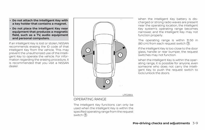
∙ Do not attach the Intelligent Key witha key holder that contains a magnet.
∙ Do not place the Intelligent Key nearequipment that produces a magneticfield, such as a TV, audio equipmentand personal computers.
If an Intelligent Key is lost or stolen, NISSANrecommends erasing the ID code of thatIntelligent Key from the vehicle. This mayprevent the unauthorized use of the Intelli-gent Key to operate the vehicle. For infor-mation regarding the erasing procedure, itis recommended that you visit a NISSANdealer.
OPERATING RANGEThe Intelligent Key functions can only beused when the Intelligent Key is within thespecified operating range from the requestswitch �1 .
When the Intelligent Key battery is dis-charged or strong radio waves are presentnear the operating location, the IntelligentKey system’s operating range becomesnarrower, and the Intelligent Key may notfunction properly.
The operating range is within 31.50 in(80 cm) from each request switch �1 .
If the Intelligent Key is too close to the doorglass, handle or rear bumper, the requestswitches may not function.
When the Intelligent Key is within the oper-ating range, it is possible for anyone, evensomeone who does not carry the Intelli-gent Key, to push the request switch tolock/unlock the doors.
LPD2864
Pre-driving checks and adjustments 3-9
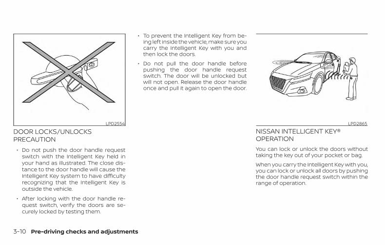
DOOR LOCKS/UNLOCKSPRECAUTION
∙ Do not push the door handle requestswitch with the Intelligent Key held inyour hand as illustrated. The close dis-tance to the door handle will cause theIntelligent Key system to have difficultyrecognizing that the Intelligent Key isoutside the vehicle.
∙ After locking with the door handle re-quest switch, verify the doors are se-curely locked by testing them.
∙ To prevent the Intelligent Key from be-ing left inside the vehicle, make sure youcarry the Intelligent Key with you andthen lock the doors.
∙ Do not pull the door handle beforepushing the door handle requestswitch. The door will be unlocked butwill not open. Release the door handleonce and pull it again to open the door.
NISSAN INTELLIGENT KEY®OPERATIONYou can lock or unlock the doors withouttaking the key out of your pocket or bag.
When you carry the Intelligent Key with you,you can lock or unlock all doors by pushingthe door handle request switch within therange of operation.
LPD2554 LPD2865
3-10 Pre-driving checks and adjustments
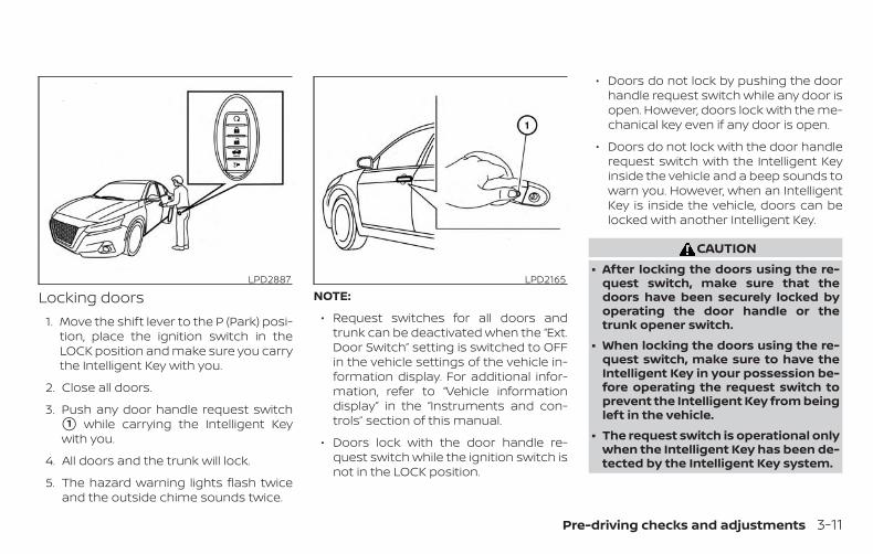
Locking doors1. Move the shift lever to the P (Park) posi-
tion, place the ignition switch in theLOCK position and make sure you carrythe Intelligent Key with you.
2. Close all doors.
3. Push any door handle request switch�1 while carrying the Intelligent Keywith you.
4. All doors and the trunk will lock.
5. The hazard warning lights flash twiceand the outside chime sounds twice.
NOTE:
∙ Request switches for all doors andtrunk can be deactivated when the “Ext.Door Switch” setting is switched to OFFin the vehicle settings of the vehicle in-formation display. For additional infor-mation, refer to “Vehicle informationdisplay” in the “Instruments and con-trols” section of this manual.
∙ Doors lock with the door handle re-quest switch while the ignition switch isnot in the LOCK position.
∙ Doors do not lock by pushing the doorhandle request switch while any door isopen. However, doors lock with the me-chanical key even if any door is open.
∙ Doors do not lock with the door handlerequest switch with the Intelligent Keyinside the vehicle and a beep sounds towarn you. However, when an IntelligentKey is inside the vehicle, doors can belocked with another Intelligent Key.
CAUTION∙ After locking the doors using the re-
quest switch, make sure that thedoors have been securely locked byoperating the door handle or thetrunk opener switch.
∙ When locking the doors using the re-quest switch, make sure to have theIntelligent Key in your possession be-fore operating the request switch toprevent the Intelligent Key from beingleft in the vehicle.
∙ The request switch is operational onlywhen the Intelligent Key has been de-tected by the Intelligent Key system.
LPD2887 LPD2165
Pre-driving checks and adjustments 3-11
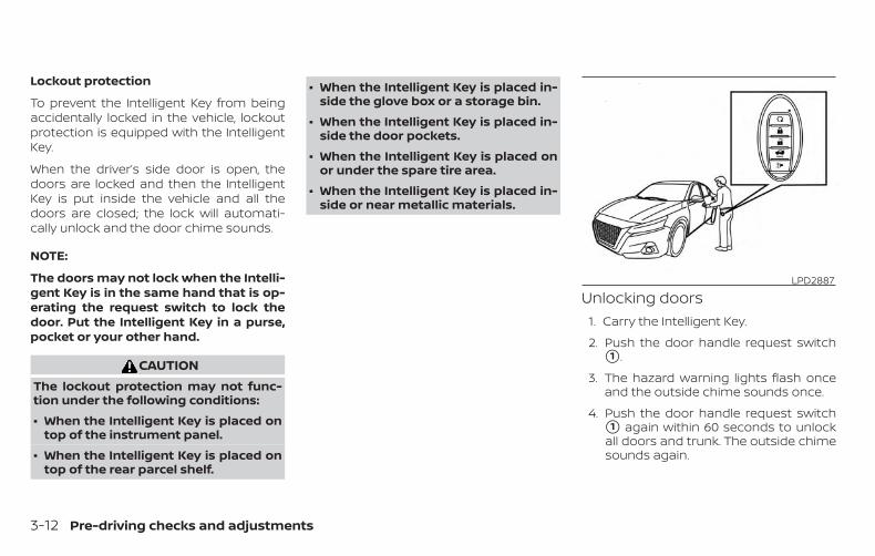
Lockout protection
To prevent the Intelligent Key from beingaccidentally locked in the vehicle, lockoutprotection is equipped with the IntelligentKey.
When the driver’s side door is open, thedoors are locked and then the IntelligentKey is put inside the vehicle and all thedoors are closed; the lock will automati-cally unlock and the door chime sounds.
NOTE:
The doors may not lock when the Intelli-gent Key is in the same hand that is op-erating the request switch to lock thedoor. Put the Intelligent Key in a purse,pocket or your other hand.
CAUTIONThe lockout protection may not func-tion under the following conditions:
∙ When the Intelligent Key is placed ontop of the instrument panel.
∙ When the Intelligent Key is placed ontop of the rear parcel shelf.
∙ When the Intelligent Key is placed in-side the glove box or a storage bin.
∙ When the Intelligent Key is placed in-side the door pockets.
∙ When the Intelligent Key is placed onor under the spare tire area.
∙ When the Intelligent Key is placed in-side or near metallic materials.
Unlocking doors1. Carry the Intelligent Key.
2. Push the door handle request switch�1 .
3. The hazard warning lights flash onceand the outside chime sounds once.
4. Push the door handle request switch�1 again within 60 seconds to unlockall doors and trunk. The outside chimesounds again.
LPD2887
3-12 Pre-driving checks and adjustments
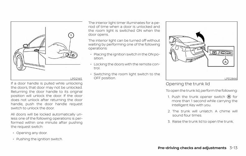
If a door handle is pulled while unlockingthe doors, that door may not be unlocked.Returning the door handle to its originalposition will unlock the door. If the doordoes not unlock after returning the doorhandle, push the door handle requestswitch to unlock the door.
All doors will be locked automatically un-less one of the following operations is per-formed within one minute after pushingthe request switch:
∙ Opening any door.
∙ Pushing the ignition switch.
The interior light timer illuminates for a pe-riod of time when a door is unlocked andthe room light is switched ON when thedoor opens.
The interior light can be turned off withoutwaiting by performing one of the followingoperations:
∙ Placing the ignition switch in the ON po-sition.
∙ Locking the doors with the remote con-trol.
∙ Switching the room light switch to theOFF position.
Opening the trunk lidTo open the trunk lid, perform the following:
1. Push the trunk opener switch �A formore than 1 second while carrying theIntelligent Key with you.
2. The trunk will unlatch. A chime willsound four times.
3. Raise the trunk lid to open the trunk.
LPD2165 LPD2866
Pre-driving checks and adjustments 3-13
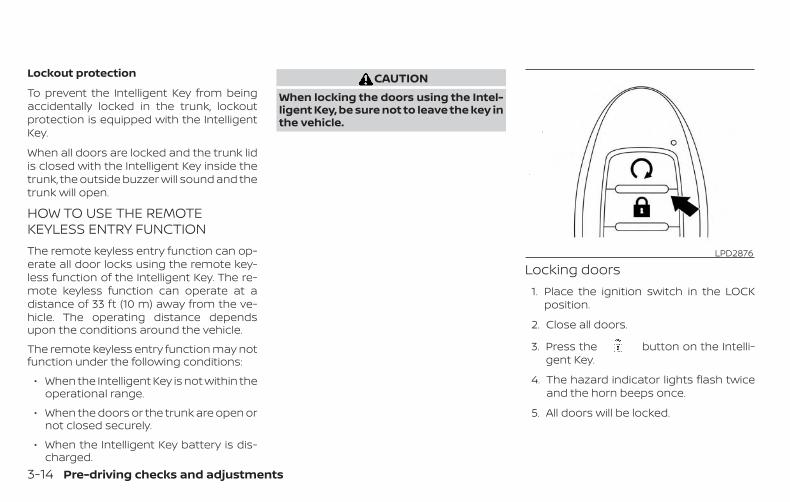
Lockout protection
To prevent the Intelligent Key from beingaccidentally locked in the trunk, lockoutprotection is equipped with the IntelligentKey.
When all doors are locked and the trunk lidis closed with the Intelligent Key inside thetrunk, the outside buzzer will sound and thetrunk will open.
HOW TO USE THE REMOTEKEYLESS ENTRY FUNCTIONThe remote keyless entry function can op-erate all door locks using the remote key-less function of the Intelligent Key. The re-mote keyless function can operate at adistance of 33 ft (10 m) away from the ve-hicle. The operating distance dependsupon the conditions around the vehicle.
The remote keyless entry function may notfunction under the following conditions:
∙ When the Intelligent Key is not within theoperational range.
∙ When the doors or the trunk are open ornot closed securely.
∙ When the Intelligent Key battery is dis-charged.
CAUTIONWhen locking the doors using the Intel-ligent Key, be sure not to leave the key inthe vehicle.
Locking doors1. Place the ignition switch in the LOCK
position.
2. Close all doors.
3. Press the button on the Intelli-gent Key.
4. The hazard indicator lights flash twiceand the horn beeps once.
5. All doors will be locked.
LPD2876
3-14 Pre-driving checks and adjustments
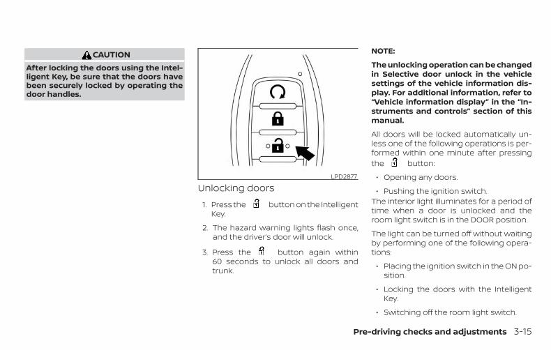
CAUTIONAfter locking the doors using the Intel-ligent Key, be sure that the doors havebeen securely locked by operating thedoor handles.
Unlocking doors
1. Press the button on the IntelligentKey.
2. The hazard warning lights flash once,and the driver’s door will unlock.
3. Press the button again within60 seconds to unlock all doors andtrunk.
NOTE:
The unlocking operation can be changedin Selective door unlock in the vehiclesettings of the vehicle information dis-play. For additional information, refer to“Vehicle information display” in the “In-struments and controls” section of thismanual.
All doors will be locked automatically un-less one of the following operations is per-formed within one minute after pressingthe button:
∙ Opening any doors.
∙ Pushing the ignition switch.The interior light illuminates for a period oftime when a door is unlocked and theroom light switch is in the DOOR position.
The light can be turned off without waitingby performing one of the following opera-tions:
∙ Placing the ignition switch in the ON po-sition.
∙ Locking the doors with the IntelligentKey.
∙ Switching off the room light switch.
LPD2877
Pre-driving checks and adjustments 3-15
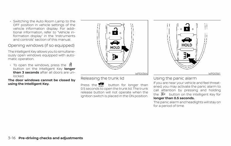
∙ Switching the Auto Room Lamp to theOFF position in vehicle settings of thevehicle information display. For addi-tional information, refer to “Vehicle in-formation display” in the “Instrumentsand controls” section of this manual.
Opening windows (if so equipped)The Intelligent Key allows you to simultane-ously open windows equipped with auto-matic operation.
∙ To open the windows, press thebutton on the Intelligent Key longerthan 3 seconds after all doors are un-locked.
The door windows cannot be closed byusing the Intelligent Key.
Releasing the trunk lidPress the button for longer than0.5 seconds to open the trunk lid. The trunkrelease button will not operate when theignition switch is placed in the ON position.
Using the panic alarmIf you are near your vehicle and feel threat-ened, you may activate the panic alarm tocall attention by pressing and holdingthe button on the Intelligent Key forlonger than 0.5 seconds.The panic alarm and headlights will stay onfor a period of time.
WPD0364 WPD0361
3-16 Pre-driving checks and adjustments
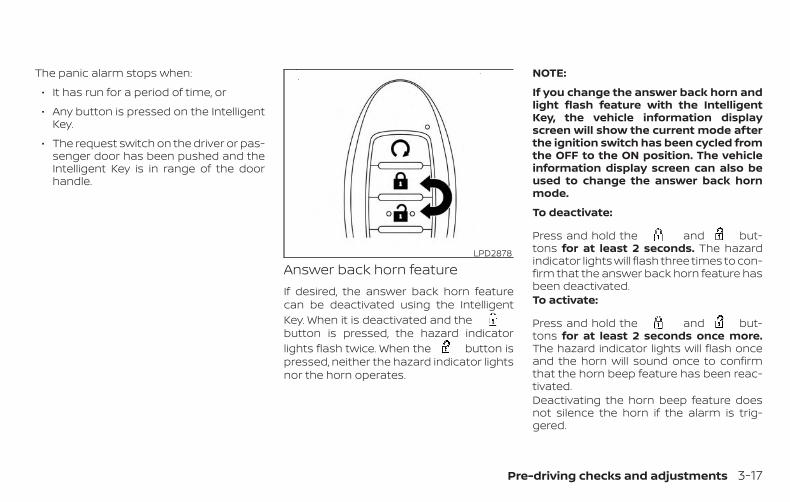
The panic alarm stops when:
∙ It has run for a period of time, or
∙ Any button is pressed on the IntelligentKey.
∙ The request switch on the driver or pas-senger door has been pushed and theIntelligent Key is in range of the doorhandle.
Answer back horn featureIf desired, the answer back horn featurecan be deactivated using the IntelligentKey. When it is deactivated and thebutton is pressed, the hazard indicatorlights flash twice. When the button ispressed, neither the hazard indicator lightsnor the horn operates.
NOTE:
If you change the answer back horn andlight flash feature with the IntelligentKey, the vehicle information displayscreen will show the current mode afterthe ignition switch has been cycled fromthe OFF to the ON position. The vehicleinformation display screen can also beused to change the answer back hornmode.
To deactivate:
Press and hold the and but-tons for at least 2 seconds. The hazardindicator lights will flash three times to con-firm that the answer back horn feature hasbeen deactivated.To activate:
Press and hold the and but-tons for at least 2 seconds once more.The hazard indicator lights will flash onceand the horn will sound once to confirmthat the horn beep feature has been reac-tivated.Deactivating the horn beep feature doesnot silence the horn if the alarm is trig-gered.
LPD2878
Pre-driving checks and adjustments 3-17
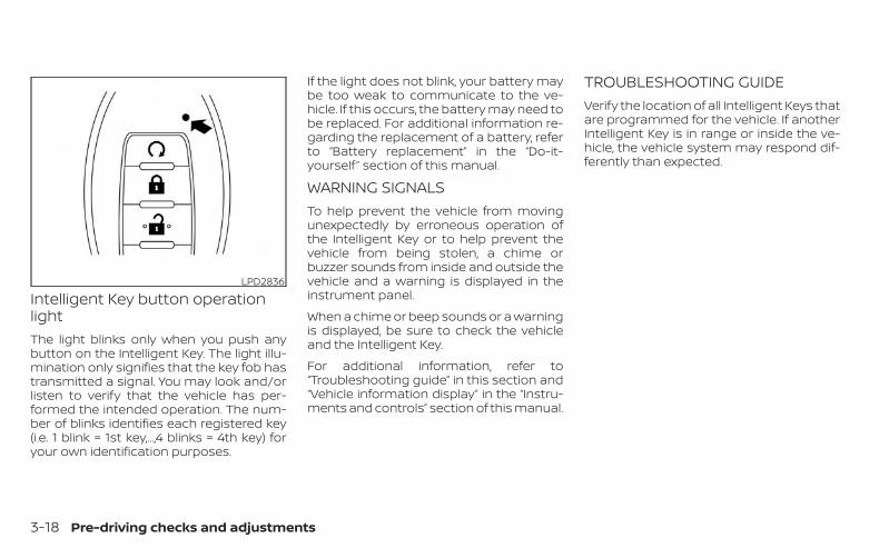
Intelligent Key button operationlightThe light blinks only when you push anybutton on the Intelligent Key. The light illu-mination only signifies that the key fob hastransmitted a signal. You may look and/orlisten to verify that the vehicle has per-formed the intended operation. The num-ber of blinks identifies each registered key(i.e. 1 blink = 1st key,...,4 blinks = 4th key) foryour own identification purposes.
If the light does not blink, your battery maybe too weak to communicate to the ve-hicle. If this occurs, the battery may need tobe replaced. For additional information re-garding the replacement of a battery, referto “Battery replacement” in the “Do-it-yourself ” section of this manual.
WARNING SIGNALSTo help prevent the vehicle from movingunexpectedly by erroneous operation ofthe Intelligent Key or to help prevent thevehicle from being stolen, a chime orbuzzer sounds from inside and outside thevehicle and a warning is displayed in theinstrument panel.
When a chime or beep sounds or a warningis displayed, be sure to check the vehicleand the Intelligent Key.
For additional information, refer to“Troubleshooting guide” in this section and“Vehicle information display” in the “Instru-ments and controls” section of this manual.
TROUBLESHOOTING GUIDEVerify the location of all Intelligent Keys thatare programmed for the vehicle. If anotherIntelligent Key is in range or inside the ve-hicle, the vehicle system may respond dif-ferently than expected.
LPD2836
3-18 Pre-driving checks and adjustments
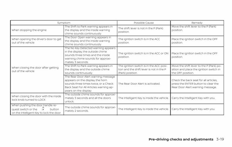
Symptom Possible Cause Remedy
When stopping the engineThe Shift to Park warning appears inthe display and the inside warningchime sounds continuously.
The shift lever is not in the P (Park)position.
Move the shift lever to the P (Park)position.
When opening the driver’s door to getout of the vehicle
The Door Open warning appears inthe display and the inside warningchime sounds continuously.
The ignition switch is in the ACCposition.
Place the ignition switch in the OFFposition.
When closing the door after gettingout of the vehicle
The No Key Detected warning appearsin the display, the outside chimesounds three times and the insidewarning chime sounds for approxi-mately 3 seconds.
The ignition switch is in the ACC or ONposition.
Place the ignition switch in the OFFposition.
The Shift to Park warning appears inthe display and the outside chimesounds continuously.
The ignition switch is in the ACC posi-tion and the shift lever is not in the P(Park) position.
Move the shift lever to the P (Park) po-sition and place the ignition switch inthe OFF position.
The Rear Door Alert warning messageappears on the display, the hornsounds three times twice, or a CheckBack Seat For All Articles warning ap-pears on the display.
The Rear Door Alert is activated.Check the back seat for all articles,press the ENTER button to clear theRear Door Alert warning message.
When closing the door with the insidelock knob turned to LOCK
The outside chime sounds for approxi-mately 3 seconds and all the doorsunlock.
The Intelligent Key is inside the vehicle. Carry the Intelligent Key with you.
When pushing the door handle re-quest switch or the buttonon the Intelligent Key to lock the door
The outside chime sounds for approxi-mately 2 seconds. The Intelligent Key is inside the vehicle. Carry the Intelligent Key with you.
Pre-driving checks and adjustments 3-19
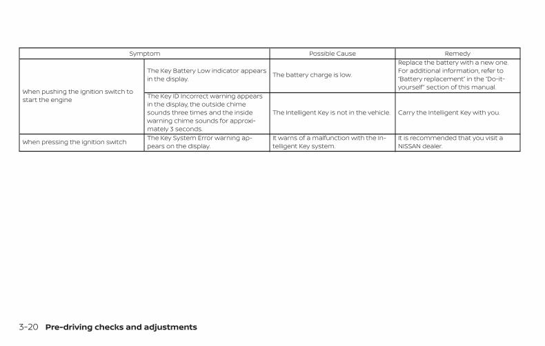
Symptom Possible Cause Remedy
When pushing the ignition switch tostart the engine
The Key Battery Low indicator appearsin the display. The battery charge is low.
Replace the battery with a new one.For additional information, refer to“Battery replacement” in the “Do-it-yourself ” section of this manual.
The Key ID Incorrect warning appearsin the display, the outside chimesounds three times and the insidewarning chime sounds for approxi-mately 3 seconds.
The Intelligent Key is not in the vehicle. Carry the Intelligent Key with you.
When pressing the ignition switch The Key System Error warning ap-pears on the display.
It warns of a malfunction with the In-telligent Key system.
It is recommended that you visit aNISSAN dealer.
3-20 Pre-driving checks and adjustments
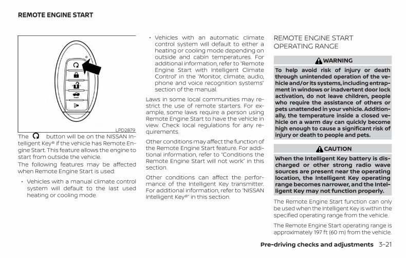
The button will be on the NISSAN In-telligent Key® if the vehicle has Remote En-gine Start. This feature allows the engine tostart from outside the vehicle.The following features may be affectedwhen Remote Engine Start is used:
∙ Vehicles with a manual climate controlsystem will default to the last usedheating or cooling mode.
∙ Vehicles with an automatic climatecontrol system will default to either aheating or cooling mode depending onoutside and cabin temperatures. Foradditional information, refer to “RemoteEngine Start with Intelligent ClimateControl” in the “Monitor, climate, audio,phone and voice recognition systems”section of the manual.
Laws in some local communities may re-strict the use of remote starters. For ex-ample, some laws require a person usingRemote Engine Start to have the vehicle inview. Check local regulations for any re-quirements.
Other conditions may affect the function ofthe Remote Engine Start feature. For addi-tional information, refer to “Conditions theRemote Engine Start will not work” in thissection.
Other conditions can affect the perfor-mance of the Intelligent Key transmitter.For additional information, refer to “NISSANIntelligent Key®” in this section.
REMOTE ENGINE STARTOPERATING RANGE
WARNINGTo help avoid risk of injury or deaththrough unintended operation of the ve-hicle and/or its systems, including entrap-ment in windows or inadvertent door lockactivation, do not leave children, peoplewho require the assistance of others orpets unattended in your vehicle. Addition-ally, the temperature inside a closed ve-hicle on a warm day can quickly becomehigh enough to cause a significant risk ofinjury or death to people and pets.
CAUTIONWhen the Intelligent Key battery is dis-charged or other strong radio wavesources are present near the operatinglocation, the Intelligent Key operatingrange becomes narrower, and the Intel-ligent Key may not function properly.
The Remote Engine Start function can onlybe used when the Intelligent Key is within thespecified operating range from the vehicle.
The Remote Engine Start operating range isapproximately 197 ft (60 m) from the vehicle.
LPD2879
REMOTE ENGINE START
Pre-driving checks and adjustments 3-21
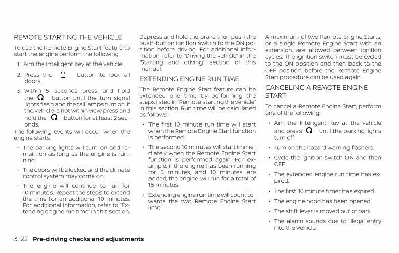
REMOTE STARTING THE VEHICLETo use the Remote Engine Start feature tostart the engine perform the following:
1. Aim the Intelligent Key at the vehicle.
2. Press the button to lock alldoors.
3. Within 5 seconds press and holdthe button until the turn signallights flash and the tail lamps turn on. Ifthe vehicle is not within view press andhold the button for at least 2 sec-onds.
The following events will occur when theengine starts:
∙ The parking lights will turn on and re-main on as long as the engine is run-ning.
∙ The doors will be locked and the climatecontrol system may come on.
∙ The engine will continue to run for10 minutes. Repeat the steps to extendthe time for an additional 10 minutes.For additional information, refer to “Ex-tending engine run time” in this section.
Depress and hold the brake then push thepush-button ignition switch to the ON po-sition before driving. For additional infor-mation, refer to “Driving the vehicle” in the“Starting and driving” section of thismanual.
EXTENDING ENGINE RUN TIMEThe Remote Engine Start feature can beextended one time by performing thesteps listed in “Remote starting the vehicle”in this section. Run time will be calculatedas follows:
∙ The first 10 minute run time will startwhen the Remote Engine Start functionis performed.
∙ The second 10 minutes will start imme-diately when the Remote Engine Startfunction is performed again. For ex-ample, if the engine has been runningfor 5 minutes, and 10 minutes areadded, the engine will run for a total of15 minutes.
∙ Extending engine run time will count to-wards the two Remote Engine Startlimit.
A maximum of two Remote Engine Starts,or a single Remote Engine Start with anextension, are allowed between ignitioncycles. The ignition switch must be cycledto the ON position and then back to theOFF position before the Remote EngineStart procedure can be used again.
CANCELING A REMOTE ENGINESTARTTo cancel a Remote Engine Start, performone of the following:
∙ Aim the Intelligent Key at the vehicleand press until the parking lightsturn off.
∙ Turn on the hazard warning flashers.
∙ Cycle the ignition switch ON and thenOFF.
∙ The extended engine run time has ex-pired.
∙ The first 10 minute timer has expired.
∙ The engine hood has been opened.
∙ The shift lever is moved out of park.
∙ The alarm sounds due to illegal entryinto the vehicle.
3-22 Pre-driving checks and adjustments
∙ The ignition switch is pushed withoutan Intelligent Key in the vehicle.
∙ The ignition switch is pushed with anIntelligent Key in the vehicle but thebrake pedal is not depressed.
CONDITIONS THE REMOTE ENGINESTART WILL NOT WORKThe Remote Engine Start will not operate ifany of the following conditions are present:
∙ The ignition switch is placed in the ONposition.
∙ The hood is not securely closed.
∙ The hazard indicator lights are on.
∙ The engine is still running. The enginemust be completely stopped. Wait atleast 6 seconds if the engine goes fromrunning to off. This is not applicablewhen extending engine run time.
∙ The button is not pressed andheld for at least 2 seconds.
∙ The button is not pressed andheld within 5 seconds of pressing thelock button.
∙ The brake is pressed.
∙ The doors are not closed and locked.
∙ The trunk is open.
∙ The Key System Error remains solid inthe vehicle information display.
∙ The alarm sounds due to illegal entryinto the vehicle.
∙ Two Remote Engine Starts, or a singleRemote Engine Start with an extension,have already been used.
∙ The vehicle is not in P (Park).
∙ There is a detected registered key al-ready inside of the vehicle.
∙ The Remote Engine Start function hasbeen switched to the OFF position inVehicle Settings of the vehicle informa-tion display. For additional information,refer to “Vehicle information display” inthe “Instruments and controls” sectionof this manual.
The Remote Engine Start may display awarning or indicator in the vehicle informa-tion display. For additional information, re-fer to “Vehicle information display” in the“Instruments and controls” section of thismanual.
Pre-driving checks and adjustments 3-23
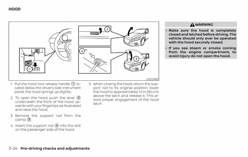
1. Pull the hood lock release handle �1 lo-cated below the driver’s side instrumentpanel; the hood springs up slightly.
2. To open the hood, push the lever �2underneath the front of the hood up-wards with your fingertips as illustratedand raise the hood.
3. Remove the support rod from theclamp �3 .
4. Insert the support rod �4 into the sloton the passenger side of the hood.
5. When closing the hood, return the sup-port rod to its original position, lowerthe hood to approximately 12 in (30 cm)above the latch and release it. This al-lows proper engagement of the hoodlatch.
WARNING∙ Make sure the hood is completely
closed and latched before driving. Thevehicle should only ever be operatedwith the hood securely closed.
∙ If you see steam or smoke comingfrom the engine compartment, toavoid injury do not open the hood.
LPD2983
HOOD
3-24 Pre-driving checks and adjustments
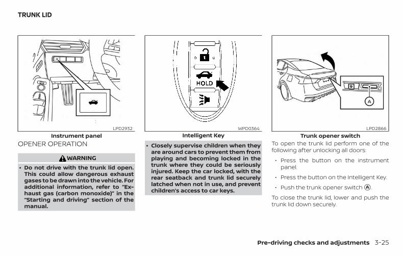
OPENER OPERATION
WARNING∙ Do not drive with the trunk lid open.
This could allow dangerous exhaustgases to be drawn into the vehicle. Foradditional information, refer to “Ex-haust gas (carbon monoxide)” in the“Starting and driving” section of themanual.
∙ Closely supervise children when theyare around cars to prevent them fromplaying and becoming locked in thetrunk where they could be seriouslyinjured. Keep the car locked, with therear seatback and trunk lid securelylatched when not in use, and preventchildren’s access to car keys.
To open the trunk lid perform one of thefollowing after unlocking all doors:
∙ Press the button on the instrumentpanel.
∙ Press the button on the Intelligent Key.
∙ Push the trunk opener switch �A .
To close the trunk lid, lower and push thetrunk lid down securely.
Instrument panelLPD2932
Intelligent KeyWPD0364
Trunk opener switchLPD2866
TRUNK LID
Pre-driving checks and adjustments 3-25
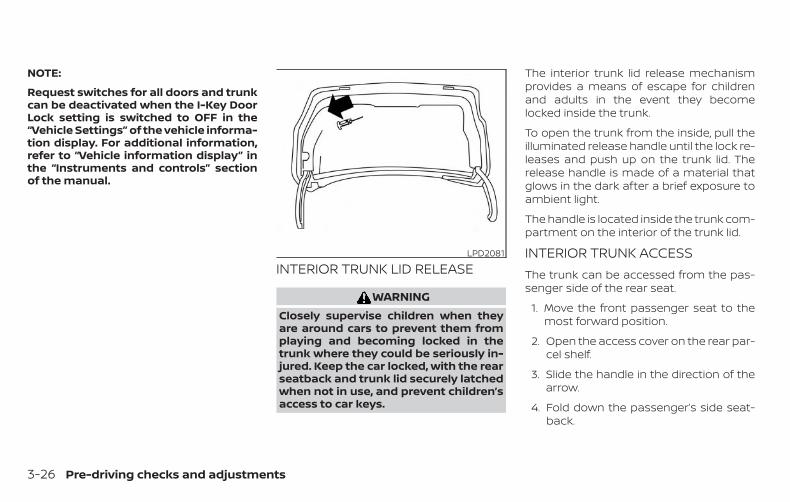
NOTE:
Request switches for all doors and trunkcan be deactivated when the I-Key DoorLock setting is switched to OFF in the“Vehicle Settings” of the vehicle informa-tion display. For additional information,refer to “Vehicle information display” inthe “Instruments and controls” sectionof the manual.
INTERIOR TRUNK LID RELEASE
WARNINGClosely supervise children when theyare around cars to prevent them fromplaying and becoming locked in thetrunk where they could be seriously in-jured. Keep the car locked, with the rearseatback and trunk lid securely latchedwhen not in use, and prevent children’saccess to car keys.
The interior trunk lid release mechanismprovides a means of escape for childrenand adults in the event they becomelocked inside the trunk.
To open the trunk from the inside, pull theilluminated release handle until the lock re-leases and push up on the trunk lid. Therelease handle is made of a material thatglows in the dark after a brief exposure toambient light.
The handle is located inside the trunk com-partment on the interior of the trunk lid.
INTERIOR TRUNK ACCESSThe trunk can be accessed from the pas-senger side of the rear seat.
1. Move the front passenger seat to themost forward position.
2. Open the access cover on the rear par-cel shelf.
3. Slide the handle in the direction of thearrow.
4. Fold down the passenger’s side seat-back.
LPD2081
3-26 Pre-driving checks and adjustments
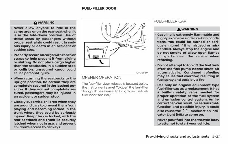
WARNING∙ Never allow anyone to ride in the
cargo area or on the rear seat when itis in the fold-down position. Use ofthese areas by passengers withoutproper restraints could result in seri-ous injury or death in an accident orsudden stop.
∙ Properly secure all cargo with ropes orstraps to help prevent it from slidingor shifting. Do not place cargo higherthan the seatbacks. In a sudden stopor collision, unsecured cargo couldcause personal injury.
∙ When returning the seatbacks to theupright position, be certain they arecompletely secured in the latched po-sition. If they are not completely se-cured, passengers may be injured inan accident or sudden stop.
∙ Closely supervise children when theyare around cars to prevent them fromplaying and becoming locked in thetrunk where they could be seriouslyinjured. Keep the car locked, with therear seatback and trunk lid securelylatched when not in use, and preventchildren’s access to car keys.
OPENER OPERATIONThe fuel-filler door release is located belowthe instrument panel. To open the fuel-fillerdoor, pull the release. To lock, close the fuel-filler door securely.
FUEL-FILLER CAP
WARNING∙ Gasoline is extremely flammable and
highly explosive under certain condi-tions. You could be burned or seri-ously injured if it is misused or mis-handled. Always stop the engine anddo not smoke or allow open flamesor sparks near the vehicle whenrefueling.
∙ Do not attempt to top off the fuel tankafter the fuel pump nozzle shuts offautomatically. Continued refuelingmay cause fuel overflow, resulting infuel spray and possibly a fire.
∙ Use only an original equipment typefuel-filler cap as a replacement. It hasa built-in safety valve needed forproper operation of the fuel systemand emission control system. An in-correct cap can result in a serious mal-function and possible injury. It couldalso cause the Malfunction Indi-cator Light (MIL) to come on.
∙ Never pour fuel into the throttle bodyto attempt to start your vehicle.
LPD2869
FUEL-FILLER DOOR
Pre-driving checks and adjustments 3-27
∙ Do not fill a portable fuel container inthe vehicle or trailer. Static electricitycan cause an explosion of flammableliquid, vapor or gas in any vehicle ortrailer. To reduce the risk of seriousinjury or death when filling portablefuel containers:
– Always place the container on theground when filling.
– Do not use electronic devices whenfilling.
– Keep the pump nozzle in contactwith the container while you arefilling it.
– Use only approved portable fuelcontainers for flammable liquid.
CAUTION∙ Do not use a fuel that contains more
than 15% ethanol in your vehicle. Foradditional information, refer to “Fuelrecommendation” in the “Technicaland consumer information” section ofthis manual.
∙ The Loose Fuel Cap warning messagewill be displayed/warning will appearif the fuel-filler cap is not properlytightened. It may take a few drivingtrips for the message to be displayed.Failure to tighten the fuel-filler capproperly after the Loose Fuel Capwarning message is displayed/warning appears may cause theMalfunction Indicator Light (MIL) toilluminate.
∙ Failure to tighten the fuel-filler capproperly may cause the Mal-function Indicator Light (MIL) to illumi-nate. If the light illuminates be-cause the fuel-filler cap is loose ormissing, tighten or install the cap andcontinue to drive the vehicle.The light should turn off after afew driving trips. If the light doesnot turn off after a few driving trips,have the vehicle inspected. It is rec-ommended that you visit a NISSANdealer for this service.
∙ For additional information, refer to“Malfunction Indicator Light (MIL)” inthe “Instruments and controls” sec-tion of this manual.
∙ If fuel is spilled on the vehicle body,flush it away with water to avoid paintdamage.
NOTE:
Changing ignition switch status duringthe refueling process may cause a delayin fuel gauge response.
3-28 Pre-driving checks and adjustments
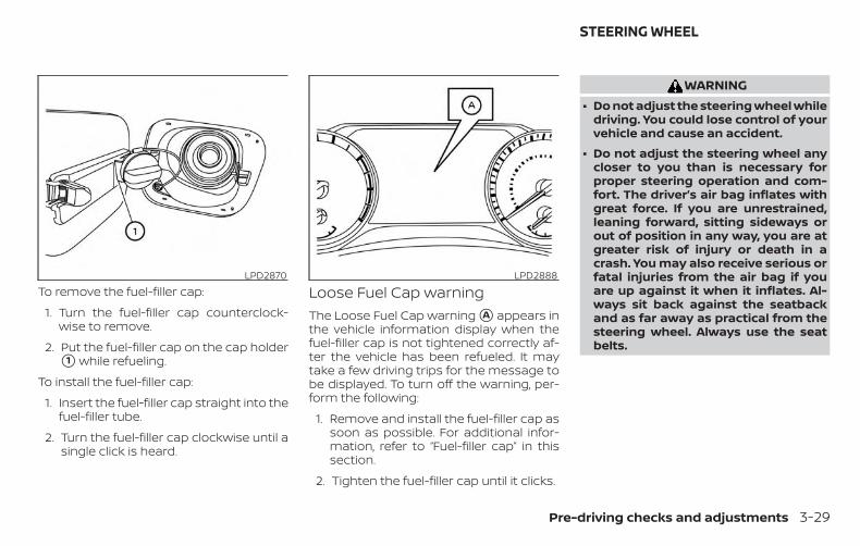
To remove the fuel-filler cap:
1. Turn the fuel-filler cap counterclock-wise to remove.
2. Put the fuel-filler cap on the cap holder�1 while refueling.
To install the fuel-filler cap:
1. Insert the fuel-filler cap straight into thefuel-filler tube.
2. Turn the fuel-filler cap clockwise until asingle click is heard.
Loose Fuel Cap warningThe Loose Fuel Cap warning �A appears inthe vehicle information display when thefuel-filler cap is not tightened correctly af-ter the vehicle has been refueled. It maytake a few driving trips for the message tobe displayed. To turn off the warning, per-form the following:
1. Remove and install the fuel-filler cap assoon as possible. For additional infor-mation, refer to “Fuel-filler cap” in thissection.
2. Tighten the fuel-filler cap until it clicks.
WARNING∙ Do not adjust the steering wheel while
driving. You could lose control of yourvehicle and cause an accident.
∙ Do not adjust the steering wheel anycloser to you than is necessary forproper steering operation and com-fort. The driver’s air bag inflates withgreat force. If you are unrestrained,leaning forward, sitting sideways orout of position in any way, you are atgreater risk of injury or death in acrash. You may also receive serious orfatal injuries from the air bag if youare up against it when it inflates. Al-ways sit back against the seatbackand as far away as practical from thesteering wheel. Always use the seatbelts.
LPD2870 LPD2888
STEERING WHEEL
Pre-driving checks and adjustments 3-29
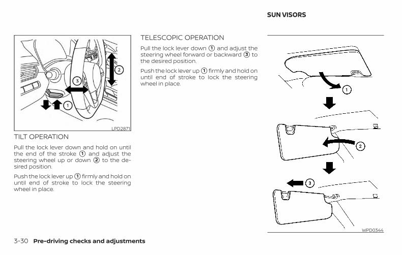
TILT OPERATIONPull the lock lever down and hold on untilthe end of the stroke �1 and adjust thesteering wheel up or down �2 to the de-sired position.
Push the lock lever up �1 firmly and hold onuntil end of stroke to lock the steeringwheel in place.
TELESCOPIC OPERATIONPull the lock lever down �1 and adjust thesteering wheel forward or backward �3 tothe desired position.
Push the lock lever up �1 firmly and hold onuntil end of stroke to lock the steeringwheel in place.
LPD2871
WPD0344
SUN VISORS
3-30 Pre-driving checks and adjustments
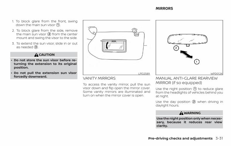
1. To block glare from the front, swingdown the main sun visor �1 .
2. To block glare from the side, removethe main sun visor �2 from the centermount and swing the visor to the side.
3. To extend the sun visor, slide in or outas needed �3 .
CAUTION∙ Do not store the sun visor before re-
turning the extension to its originalposition.
∙ Do not pull the extension sun visorforcedly downward. VANITY MIRRORS
To access the vanity mirror, pull the sunvisor down and flip open the mirror cover.Some vanity mirrors are illuminated andturn on when the mirror cover is open.
MANUAL ANTI-GLARE REARVIEWMIRROR (if so equipped)Use the night position �1 to reduce glarefrom the headlights of vehicles behind youat night.
Use the day position �2 when driving indaylight hours.
WARNINGUse the night position only when neces-sary, because it reduces rear viewclarity.
LPD2589 WPD0126
MIRRORS
Pre-driving checks and adjustments 3-31
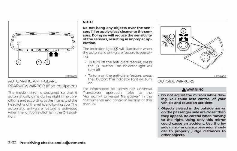
AUTOMATIC ANTI-GLAREREARVIEW MIRROR (if so equipped)The inside mirror is designed so that itautomatically dims during night time con-ditions and according to the intensity of theheadlights of the vehicle following you. Theautomatic anti-glare feature is activatedwhen the ignition switch is in the ON posi-tion.
NOTE:
Do not hang any objects over the sen-sors �1 or apply glass cleaner to the sen-sors. Doing so will reduce the sensitivityof the sensors, resulting in improper op-eration.
The indicator light �2 will illuminate whenthe automatic anti-glare feature is operat-ing.
∙ To turn off the anti-glare feature, pressthe O button. The indicator light willturn off.
∙ To turn on the anti-glare feature, pressthe | button. The indicator light will turnon.
For information on HomeLink® UniversalTransceiver operation, refer to the“HomeLink® Universal Transceiver” in the“Instruments and controls” section of thismanual.
OUTSIDE MIRRORS
WARNING∙ Do not adjust the mirrors while driv-
ing. You could lose control of yourvehicle and cause an accident.
∙ Objects viewed in the outside mirroron the passenger side are closer thanthey appear. Be careful when movingto the right. Using only this mirrorcould cause an accident. Use the in-side mirror or glance over your shoul-der to properly judge distances toother objects.
LPD0469 LPD2452
3-32 Pre-driving checks and adjustments
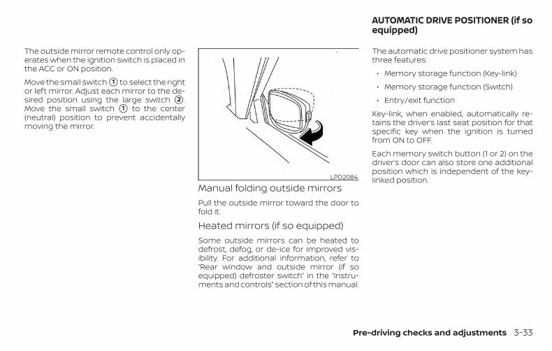
The outside mirror remote control only op-erates when the ignition switch is placed inthe ACC or ON position.
Move the small switch �1 to select the rightor left mirror. Adjust each mirror to the de-sired position using the large switch �2 .Move the small switch �1 to the center(neutral) position to prevent accidentallymoving the mirror.
Manual folding outside mirrorsPull the outside mirror toward the door tofold it.
Heated mirrors (if so equipped)Some outside mirrors can be heated todefrost, defog, or de-ice for improved vis-ibility. For additional information, refer to“Rear window and outside mirror (if soequipped) defroster switch” in the “Instru-ments and controls” section of this manual.
The automatic drive positioner system hasthree features:
∙ Memory storage function (Key-link)
∙ Memory storage function (Switch)
∙ Entry/exit function
Key-link, when enabled, automatically re-tains the driver’s last seat position for thatspecific key when the ignition is turnedfrom ON to OFF.
Each memory switch button (1 or 2) on thedriver’s door can also store one additionalposition which is independent of the key-linked position.LPD2084
AUTOMATIC DRIVE POSITIONER (if soequipped)
Pre-driving checks and adjustments 3-33
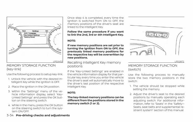
MEMORY STORAGE FUNCTION(key-link)Use the following process to setup key-link:
1. Unlock the vehicle with the desired In-telligent Key while the ignition is OFF.
2. Place the ignition in the ON position.
3. Within the “Settings” menu of the ve-hicle information display, select “Key-Linked Settings” and press the OK but-ton on the steering switch.
4. While in the menu, press the OK buttonon the steering switch to turn the sys-tem ON/OFF.
Once step 4 is completed, every time theignition is switched from ON to OFF, thememory positions of the driver’s seat arelinked to the Intelligent Key.
Follow the same procedure if you wantto link the 2nd, 3rd or 4th Intelligent Key.
NOTE:
If new memory positions are set prior toturning the ignition from ON to OFF, thepreviously linked memory positions forthe respective key will be overwritten bynew positions.
Recalling Intelligent Key memorypositionsIf the “Key-Linked Settings” are enabled inthe vehicle information display for that par-ticular key, every time you enter the vehiclethe driver’s seat will automatically move tothe driver’s last position of the respectiveIntelligent Key.
NOTE:
The key-linked memory positions can bedifferent from the positions stored in thememory switch (1 or 2).
MEMORY STORAGE FUNCTION(switch)Use the following process to manuallystore the two memory positions in theswitch:
1. The vehicle should be stopped whilesetting the memory.
2. Adjust the driver’s seat to the desiredpositions by manually operating eachadjusting switch. For additional infor-mation, refer to “Seats” in the “Safety—Seats, seat belts and supplemental re-straint system” section of this manual.
LPD2432 LPD2872
3-34 Pre-driving checks and adjustments
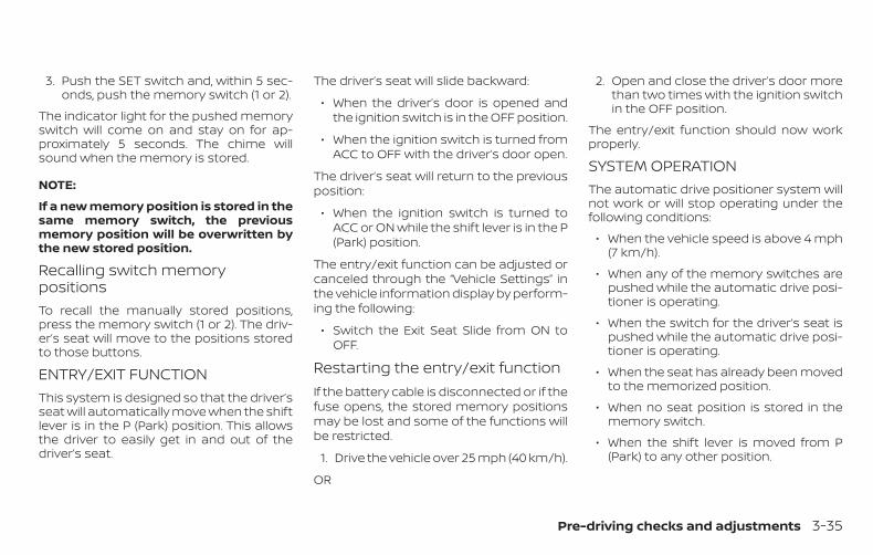
3. Push the SET switch and, within 5 sec-onds, push the memory switch (1 or 2).
The indicator light for the pushed memoryswitch will come on and stay on for ap-proximately 5 seconds. The chime willsound when the memory is stored.
NOTE:
If a new memory position is stored in thesame memory switch, the previousmemory position will be overwritten bythe new stored position.
Recalling switch memorypositionsTo recall the manually stored positions,press the memory switch (1 or 2). The driv-er’s seat will move to the positions storedto those buttons.
ENTRY/EXIT FUNCTIONThis system is designed so that the driver’sseat will automatically move when the shiftlever is in the P (Park) position. This allowsthe driver to easily get in and out of thedriver’s seat.
The driver’s seat will slide backward:
∙ When the driver’s door is opened andthe ignition switch is in the OFF position.
∙ When the ignition switch is turned fromACC to OFF with the driver’s door open.
The driver’s seat will return to the previousposition:
∙ When the ignition switch is turned toACC or ON while the shift lever is in the P(Park) position.
The entry/exit function can be adjusted orcanceled through the “Vehicle Settings” inthe vehicle information display by perform-ing the following:
∙ Switch the Exit Seat Slide from ON toOFF.
Restarting the entry/exit functionIf the battery cable is disconnected or if thefuse opens, the stored memory positionsmay be lost and some of the functions willbe restricted.
1. Drive the vehicle over 25 mph (40 km/h).
OR
2. Open and close the driver’s door morethan two times with the ignition switchin the OFF position.
The entry/exit function should now workproperly.
SYSTEM OPERATIONThe automatic drive positioner system willnot work or will stop operating under thefollowing conditions:
∙ When the vehicle speed is above 4 mph(7 km/h).
∙ When any of the memory switches arepushed while the automatic drive posi-tioner is operating.
∙ When the switch for the driver’s seat ispushed while the automatic drive posi-tioner is operating.
∙ When the seat has already been movedto the memorized position.
∙ When no seat position is stored in thememory switch.
∙ When the shift lever is moved from P(Park) to any other position.
Pre-driving checks and adjustments 3-35
4 Monitor, climate, audio, phone andvoice recognition systems
NissanConnect® Owner’s Manual . . . . . . . . . . . . . . . . 4-2RearView Monitor (if so equipped) . . . . . . . . . . . . . . . 4-3
RearView Monitor system operation . . . . . . . . . . 4-4How to read the displayed lines. . . . . . . . . . . . . . . 4-5Difference between predicted andactual distances. . . . . . . . . . . . . . . . . . . . . . . . . . . . . . 4-5How to park with predicted courselines . . . . . . . . . . . . . . . . . . . . . . . . . . . . . . . . . . . . . . . . . . 4-7Adjusting the screen . . . . . . . . . . . . . . . . . . . . . . . . . 4-8How to turn on and off predictedcourse lines . . . . . . . . . . . . . . . . . . . . . . . . . . . . . . . . . . 4-9RearView Monitor system limitations . . . . . . . . . 4-9System maintenance. . . . . . . . . . . . . . . . . . . . . . . . 4-10
Intelligent Around View Monitor(if so equipped) . . . . . . . . . . . . . . . . . . . . . . . . . . . . . . . . . .4-11
Intelligent Around View Monitor systemoperation. . . . . . . . . . . . . . . . . . . . . . . . . . . . . . . . . . . . 4-12Difference between predicted andactual distances. . . . . . . . . . . . . . . . . . . . . . . . . . . . . 4-16How to park with predicted courselines . . . . . . . . . . . . . . . . . . . . . . . . . . . . . . . . . . . . . . . . . 4-18How to switch the display . . . . . . . . . . . . . . . . . . . 4-19
Adjusting the screen . . . . . . . . . . . . . . . . . . . . . . . . 4-19Intelligent Around View Monitor systemlimitations . . . . . . . . . . . . . . . . . . . . . . . . . . . . . . . . . . . 4-20System maintenance. . . . . . . . . . . . . . . . . . . . . . . . 4-22
Moving Object Detection (MOD)(if so equipped) . . . . . . . . . . . . . . . . . . . . . . . . . . . . . . . . . 4-23
MOD system operation . . . . . . . . . . . . . . . . . . . . . . 4-24Turning MOD on and off (if so equipped) . . . . . 4-26MOD system limitations . . . . . . . . . . . . . . . . . . . . . 4-26System maintenance. . . . . . . . . . . . . . . . . . . . . . . . 4-27
Vents. . . . . . . . . . . . . . . . . . . . . . . . . . . . . . . . . . . . . . . . . . . 4-28Heater and air conditioner (manual)(if so equipped) . . . . . . . . . . . . . . . . . . . . . . . . . . . . . . . . . 4-29
Controls . . . . . . . . . . . . . . . . . . . . . . . . . . . . . . . . . . . . . 4-30Heater operation . . . . . . . . . . . . . . . . . . . . . . . . . . . . 4-30Air conditioner operation . . . . . . . . . . . . . . . . . . . . 4-32Air flow charts . . . . . . . . . . . . . . . . . . . . . . . . . . . . . . . 4-33
Heater and air conditioner (automatic)(if so equipped) . . . . . . . . . . . . . . . . . . . . . . . . . . . . . . . . . 4-37
Automatic operation . . . . . . . . . . . . . . . . . . . . . . . . 4-38Manual operation . . . . . . . . . . . . . . . . . . . . . . . . . . . 4-39Operating tips . . . . . . . . . . . . . . . . . . . . . . . . . . . . . . .4-40
Servicing air conditioner . . . . . . . . . . . . . . . . . . . . . . . . 4-41USB/iPod® charging port . . . . . . . . . . . . . . . . . . . . . . . 4-42
Antenna. . . . . . . . . . . . . . . . . . . . . . . . . . . . . . . . . . . . . . . . 4-42Car phone or CB radio . . . . . . . . . . . . . . . . . . . . . . . . . . 4-42
Refer to the NissanConnect® Owner’sManual that includes the following infor-mation.
∙ NissanConnect® Services
∙ Navigation system (if so equipped)
∙ Audio system
∙ Apple CarPlay®
∙ Android AutoTM
∙ Bluetooth® Hands-Free Phone system
∙ Viewing information
∙ Other settings
∙ Voice recognition
∙ General system information
NISSANCONNECT® OWNER’SMANUAL
4-2 Monitor, climate, audio, phone and voice recognition systems
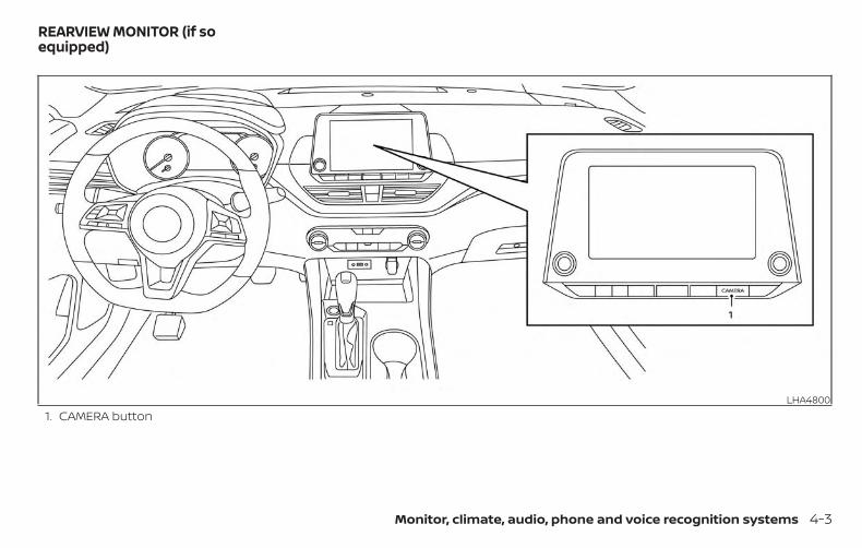
1. CAMERA buttonLHA4800
REARVIEW MONITOR (if soequipped)
Monitor, climate, audio, phone and voice recognition systems 4-3
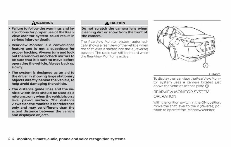
WARNING∙ Failure to follow the warnings and in-
structions for proper use of the Rear-View Monitor system could result inserious injury or death.
∙ RearView Monitor is a conveniencefeature and is not a substitute forproper backing. Always turn and lookout the windows and check mirrors tobe sure that it is safe to move beforeoperating the vehicle. Always back upslowly.
∙ The system is designed as an aid tothe driver in showing large stationaryobjects directly behind the vehicle, tohelp avoid damaging the vehicle.
∙ The distance guide lines and the ve-hicle width lines should be used as areference only when the vehicle is on alevel paved surface. The distanceviewed on the monitor is for referenceonly and may be different than theactual distance between the vehicleand displayed objects.
CAUTIONDo not scratch the camera lens whencleaning dirt or snow from the front ofthe camera.
The RearView Monitor system automati-cally shows a rear view of the vehicle whenthe shift lever is shifted into the R (Reverse)position. The radio can still be heard whilethe RearView Monitor is active.
To display the rear view, the RearView Moni-tor system uses a camera located justabove the vehicle’s license plate �1 .
REARVIEW MONITOR SYSTEMOPERATIONWith the ignition switch in the ON position,move the shift lever to the R (Reverse) po-sition to operate the RearView Monitor.
LHA4801
4-4 Monitor, climate, audio, phone and voice recognition systems
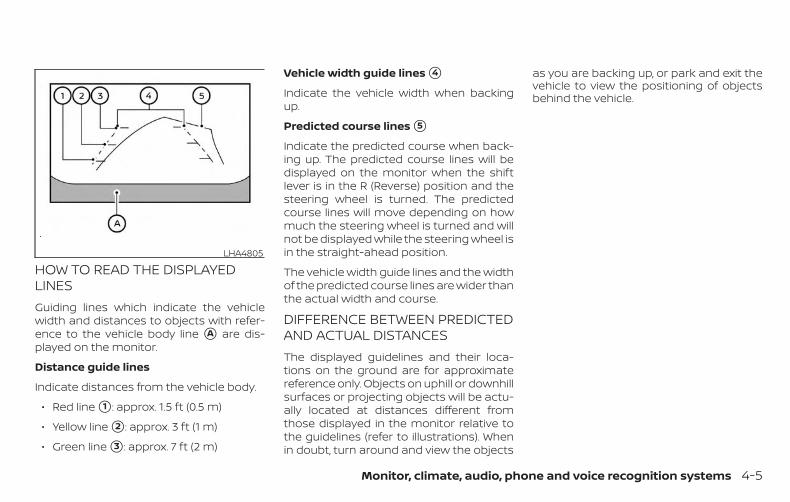
HOW TO READ THE DISPLAYEDLINESGuiding lines which indicate the vehiclewidth and distances to objects with refer-ence to the vehicle body line �A are dis-played on the monitor.
Distance guide lines
Indicate distances from the vehicle body.
∙ Red line �1 : approx. 1.5 ft (0.5 m)
∙ Yellow line �2 : approx. 3 ft (1 m)
∙ Green line �3 : approx. 7 ft (2 m)
Vehicle width guide lines �4
Indicate the vehicle width when backingup.
Predicted course lines �5
Indicate the predicted course when back-ing up. The predicted course lines will bedisplayed on the monitor when the shiftlever is in the R (Reverse) position and thesteering wheel is turned. The predictedcourse lines will move depending on howmuch the steering wheel is turned and willnot be displayed while the steering wheel isin the straight-ahead position.
The vehicle width guide lines and the widthof the predicted course lines are wider thanthe actual width and course.
DIFFERENCE BETWEEN PREDICTEDAND ACTUAL DISTANCESThe displayed guidelines and their loca-tions on the ground are for approximatereference only. Objects on uphill or downhillsurfaces or projecting objects will be actu-ally located at distances different fromthose displayed in the monitor relative tothe guidelines (refer to illustrations). Whenin doubt, turn around and view the objects
as you are backing up, or park and exit thevehicle to view the positioning of objectsbehind the vehicle.
LHA4805
Monitor, climate, audio, phone and voice recognition systems 4-5
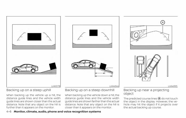
Backing up on a steep uphillWhen backing up the vehicle up a hill, thedistance guide lines and the vehicle widthguide lines are shown closer than the actualdistance. Note that any object on the hill isfurther than it appears on the monitor.
Backing up on a steep downhillWhen backing up the vehicle down a hill, thedistance guide lines and the vehicle widthguide lines are shown farther than the actualdistance. Note that any object on the hill iscloser than it appears on the monitor.
Backing up near a projectingobjectThe predicted course lines �A do not touchthe object in the display. However, the ve-hicle may hit the object if it projects overthe actual backing up course.
LHA5178 LHA4944 LHA4995
4-6 Monitor, climate, audio, phone and voice recognition systems
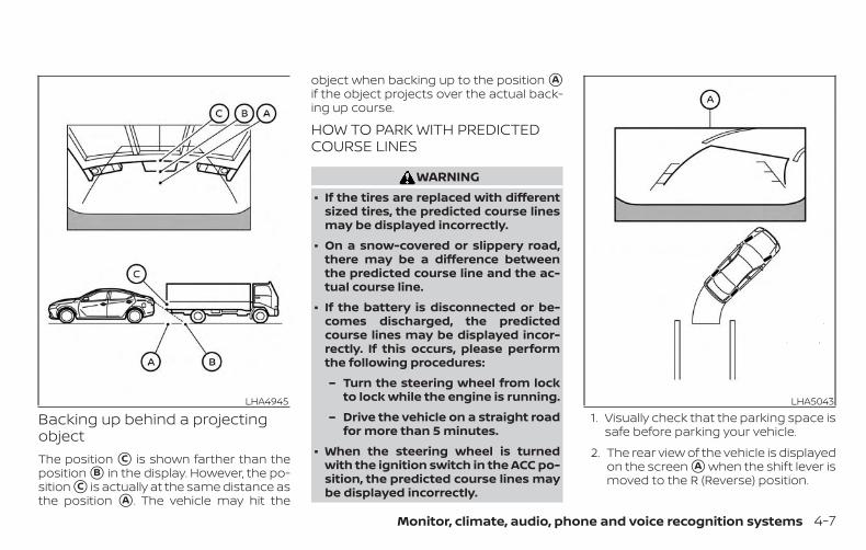
Backing up behind a projectingobjectThe position �C is shown farther than theposition �B in the display. However, the po-sition �C is actually at the same distance asthe position �A . The vehicle may hit the
object when backing up to the position �Aif the object projects over the actual back-ing up course.
HOW TO PARK WITH PREDICTEDCOURSE LINES
WARNING∙ If the tires are replaced with different
sized tires, the predicted course linesmay be displayed incorrectly.
∙ On a snow-covered or slippery road,there may be a difference betweenthe predicted course line and the ac-tual course line.
∙ If the battery is disconnected or be-comes discharged, the predictedcourse lines may be displayed incor-rectly. If this occurs, please performthe following procedures:
– Turn the steering wheel from lockto lock while the engine is running.
– Drive the vehicle on a straight roadfor more than 5 minutes.
∙ When the steering wheel is turnedwith the ignition switch in the ACC po-sition, the predicted course lines maybe displayed incorrectly.
1. Visually check that the parking space issafe before parking your vehicle.
2. The rear view of the vehicle is displayedon the screen �A when the shift lever ismoved to the R (Reverse) position.
LHA4945 LHA5043
Monitor, climate, audio, phone and voice recognition systems 4-7
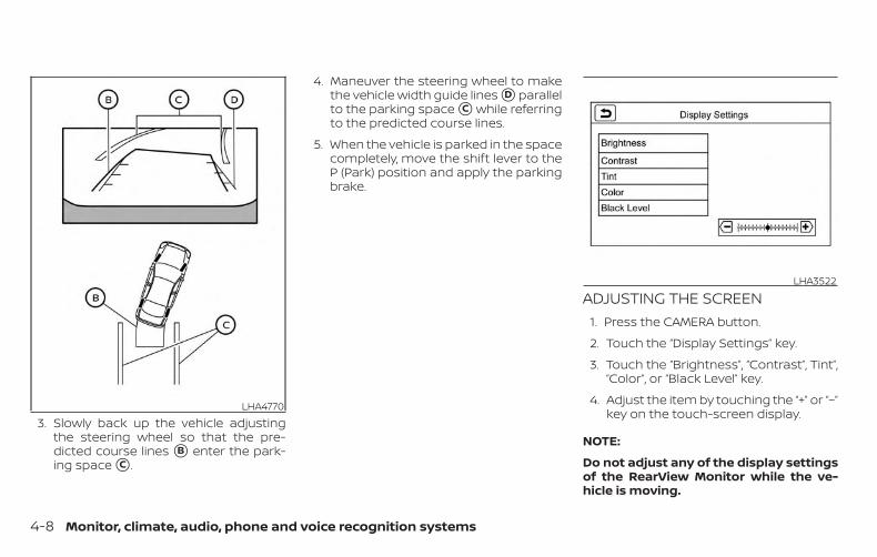
3. Slowly back up the vehicle adjustingthe steering wheel so that the pre-dicted course lines �B enter the park-ing space �C .
4. Maneuver the steering wheel to makethe vehicle width guide lines �D parallelto the parking space �C while referringto the predicted course lines.
5. When the vehicle is parked in the spacecompletely, move the shift lever to theP (Park) position and apply the parkingbrake.
ADJUSTING THE SCREEN1. Press the CAMERA button.
2. Touch the “Display Settings” key.
3. Touch the “Brightness”, “Contrast”, Tint”,“Color”, or “Black Level” key.
4. Adjust the item by touching the “+” or “–”key on the touch-screen display.
NOTE:
Do not adjust any of the display settingsof the RearView Monitor while the ve-hicle is moving.
LHA4770
LHA3522
4-8 Monitor, climate, audio, phone and voice recognition systems
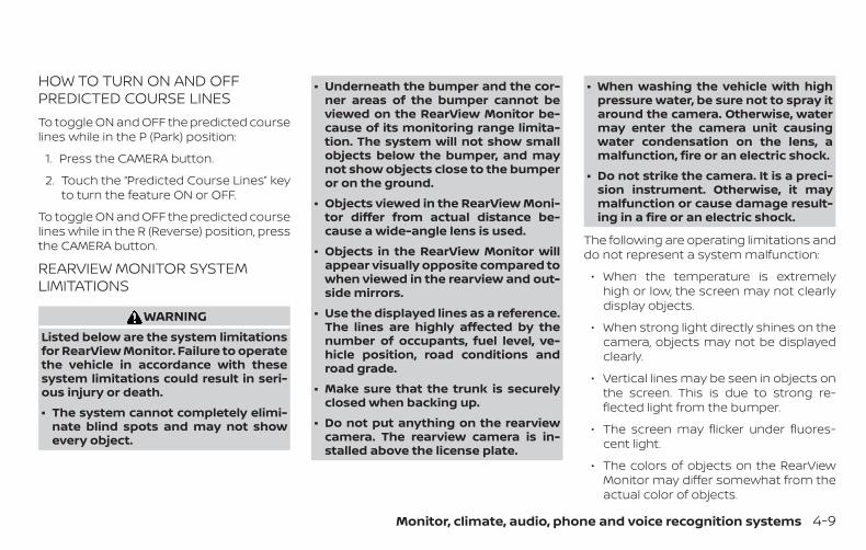
HOW TO TURN ON AND OFFPREDICTED COURSE LINESTo toggle ON and OFF the predicted courselines while in the P (Park) position:
1. Press the CAMERA button.
2. Touch the “Predicted Course Lines” keyto turn the feature ON or OFF.
To toggle ON and OFF the predicted courselines while in the R (Reverse) position, pressthe CAMERA button.
REARVIEW MONITOR SYSTEMLIMITATIONS
WARNINGListed below are the system limitationsfor RearView Monitor. Failure to operatethe vehicle in accordance with thesesystem limitations could result in seri-ous injury or death.
∙ The system cannot completely elimi-nate blind spots and may not showevery object.
∙ Underneath the bumper and the cor-ner areas of the bumper cannot beviewed on the RearView Monitor be-cause of its monitoring range limita-tion. The system will not show smallobjects below the bumper, and maynot show objects close to the bumperor on the ground.
∙ Objects viewed in the RearView Moni-tor differ from actual distance be-cause a wide-angle lens is used.
∙ Objects in the RearView Monitor willappear visually opposite compared towhen viewed in the rearview and out-side mirrors.
∙ Use the displayed lines as a reference.The lines are highly affected by thenumber of occupants, fuel level, ve-hicle position, road conditions androad grade.
∙ Make sure that the trunk is securelyclosed when backing up.
∙ Do not put anything on the rearviewcamera. The rearview camera is in-stalled above the license plate.
∙ When washing the vehicle with highpressure water, be sure not to spray itaround the camera. Otherwise, watermay enter the camera unit causingwater condensation on the lens, amalfunction, fire or an electric shock.
∙ Do not strike the camera. It is a preci-sion instrument. Otherwise, it maymalfunction or cause damage result-ing in a fire or an electric shock.
The following are operating limitations anddo not represent a system malfunction:
∙ When the temperature is extremelyhigh or low, the screen may not clearlydisplay objects.
∙ When strong light directly shines on thecamera, objects may not be displayedclearly.
∙ Vertical lines may be seen in objects onthe screen. This is due to strong re-flected light from the bumper.
∙ The screen may flicker under fluores-cent light.
∙ The colors of objects on the RearViewMonitor may differ somewhat from theactual color of objects.
Monitor, climate, audio, phone and voice recognition systems 4-9
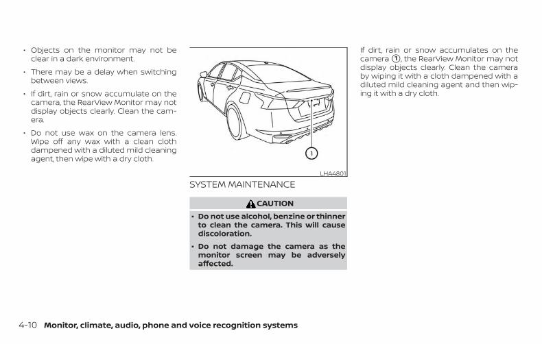
∙ Objects on the monitor may not beclear in a dark environment.
∙ There may be a delay when switchingbetween views.
∙ If dirt, rain or snow accumulate on thecamera, the RearView Monitor may notdisplay objects clearly. Clean the cam-era.
∙ Do not use wax on the camera lens.Wipe off any wax with a clean clothdampened with a diluted mild cleaningagent, then wipe with a dry cloth.
SYSTEM MAINTENANCE
CAUTION∙ Do not use alcohol, benzine or thinner
to clean the camera. This will causediscoloration.
∙ Do not damage the camera as themonitor screen may be adverselyaffected.
If dirt, rain or snow accumulates on thecamera �1 , the RearView Monitor may notdisplay objects clearly. Clean the cameraby wiping it with a cloth dampened with adiluted mild cleaning agent and then wip-ing it with a dry cloth.
LHA4801
4-10 Monitor, climate, audio, phone and voice recognition systems
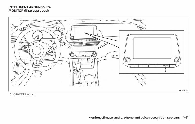
1. CAMERA buttonLHA4800
INTELLIGENT AROUND VIEWMONITOR (if so equipped)
Monitor, climate, audio, phone and voice recognition systems 4-11
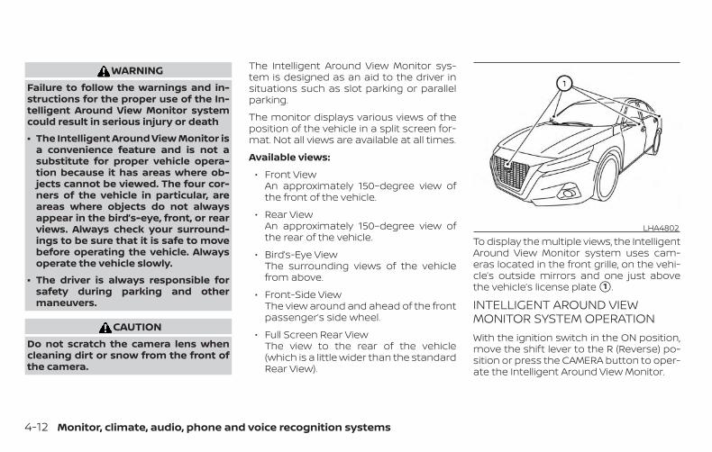
WARNINGFailure to follow the warnings and in-structions for the proper use of the In-telligent Around View Monitor systemcould result in serious injury or death
∙ The Intelligent Around View Monitor isa convenience feature and is not asubstitute for proper vehicle opera-tion because it has areas where ob-jects cannot be viewed. The four cor-ners of the vehicle in particular, areareas where objects do not alwaysappear in the bird’s-eye, front, or rearviews. Always check your surround-ings to be sure that it is safe to movebefore operating the vehicle. Alwaysoperate the vehicle slowly.
∙ The driver is always responsible forsafety during parking and othermaneuvers.
CAUTIONDo not scratch the camera lens whencleaning dirt or snow from the front ofthe camera.
The Intelligent Around View Monitor sys-tem is designed as an aid to the driver insituations such as slot parking or parallelparking.
The monitor displays various views of theposition of the vehicle in a split screen for-mat. Not all views are available at all times.
Available views:
∙ Front ViewAn approximately 150–degree view ofthe front of the vehicle.
∙ Rear ViewAn approximately 150–degree view ofthe rear of the vehicle.
∙ Bird’s-Eye ViewThe surrounding views of the vehiclefrom above.
∙ Front-Side ViewThe view around and ahead of the frontpassenger’s side wheel.
∙ Full Screen Rear ViewThe view to the rear of the vehicle(which is a little wider than the standardRear View).
To display the multiple views, the IntelligentAround View Monitor system uses cam-eras located in the front grille, on the vehi-cle’s outside mirrors and one just abovethe vehicle’s license plate �1 .
INTELLIGENT AROUND VIEWMONITOR SYSTEM OPERATIONWith the ignition switch in the ON position,move the shift lever to the R (Reverse) po-sition or press the CAMERA button to oper-ate the Intelligent Around View Monitor.
LHA4802
4-12 Monitor, climate, audio, phone and voice recognition systems
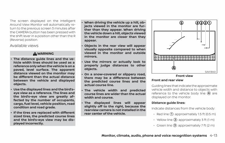
The screen displayed on the IntelligentAround View Monitor will automatically re-turn to the previous screen 3 minutes afterthe CAMERA button has been pressed withthe shift lever in a position other than the R(Reverse) position.
Available views
WARNING∙ The distance guide lines and the ve-
hicle width lines should be used as areference only when the vehicle is on apaved, level surface. The apparentdistance viewed on the monitor maybe different than the actual distancebetween the vehicle and displayedobjects.
∙ Use the displayed lines and the bird’s-eye view as a reference. The lines andthe bird’s-eye view are greatly af-fected by the number of occupants,cargo, fuel level, vehicle position, roadcondition and road grade.
∙ If the tires are replaced with differentsized tires, the predicted course linesand the bird’s-eye view may be dis-played incorrectly.
∙ When driving the vehicle up a hill, ob-jects viewed in the monitor are fur-ther than they appear. When drivingthe vehicle down a hill, objects viewedin the monitor are closer than theyappear.
∙ Objects in the rear view will appearvisually opposite compared to whenviewed in the monitor and outsidemirrors.
∙ Use the mirrors or actually look toproperly judge distances to otherobjects.
∙ On a snow-covered or slippery road,there may be a difference betweenthe predicted course lines and theactual course line.
∙ The vehicle width and predictedcourse lines are wider than the actualwidth and course.
∙ The displayed lines will appearslightly off to the right, because therearview camera is not installed in therear center of the vehicle.
Front and rear view
Guiding lines that indicate the approximatevehicle width and distance to objects withreference to the vehicle body line �A aredisplayed on the monitor.
Distance guide lines:
Indicate distances from the vehicle body:
∙ Red line �1 : approximately 1.5 ft (0.5 m)
∙ Yellow line �2 : approximately 3 ft (1 m)
∙ Green line �3 : approximately 7 ft (2 m)
Front viewSAA1840
Monitor, climate, audio, phone and voice recognition systems 4-13
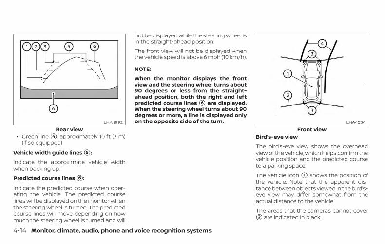
∙ Green line �4 : approximately 10 ft (3 m)(if so equipped)
Vehicle width guide lines �5 :
Indicate the approximate vehicle widthwhen backing up.
Predicted course lines �6 :
Indicate the predicted course when oper-ating the vehicle. The predicted courselines will be displayed on the monitor whenthe steering wheel is turned. The predictedcourse lines will move depending on howmuch the steering wheel is turned and will
not be displayed while the steering wheel isin the straight-ahead position.
The front view will not be displayed whenthe vehicle speed is above 6 mph (10 km/h).
NOTE:
When the monitor displays the frontview and the steering wheel turns about90 degrees or less from the straight-ahead position, both the right and leftpredicted course lines �6 are displayed.When the steering wheel turns about 90degrees or more, a line is displayed onlyon the opposite side of the turn.
Bird’s-eye view
The bird’s-eye view shows the overheadview of the vehicle, which helps confirm thevehicle position and the predicted courseto a parking space.
The vehicle icon �1 shows the position ofthe vehicle. Note that the apparent dis-tance between objects viewed in the bird’s-eye view may differ somewhat from theactual distance to the vehicle.
The areas that the cameras cannot cover�2 are indicated in black.
Rear viewLHA4992
Front viewLHA4534
4-14 Monitor, climate, audio, phone and voice recognition systems
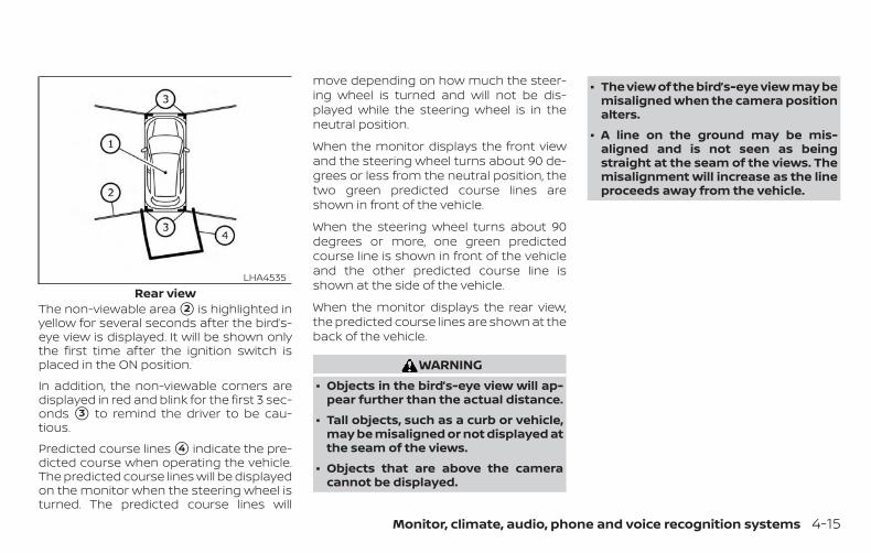
The non-viewable area �2 is highlighted inyellow for several seconds after the bird’s-eye view is displayed. It will be shown onlythe first time after the ignition switch isplaced in the ON position.
In addition, the non-viewable corners aredisplayed in red and blink for the first 3 sec-onds �3 to remind the driver to be cau-tious.
Predicted course lines �4 indicate the pre-dicted course when operating the vehicle.The predicted course lines will be displayedon the monitor when the steering wheel isturned. The predicted course lines will
move depending on how much the steer-ing wheel is turned and will not be dis-played while the steering wheel is in theneutral position.
When the monitor displays the front viewand the steering wheel turns about 90 de-grees or less from the neutral position, thetwo green predicted course lines areshown in front of the vehicle.
When the steering wheel turns about 90degrees or more, one green predictedcourse line is shown in front of the vehicleand the other predicted course line isshown at the side of the vehicle.
When the monitor displays the rear view,the predicted course lines are shown at theback of the vehicle.
WARNING∙ Objects in the bird’s-eye view will ap-
pear further than the actual distance.
∙ Tall objects, such as a curb or vehicle,may be misaligned or not displayed atthe seam of the views.
∙ Objects that are above the cameracannot be displayed.
∙ The view of the bird’s-eye view may bemisaligned when the camera positionalters.
∙ A line on the ground may be mis-aligned and is not seen as beingstraight at the seam of the views. Themisalignment will increase as the lineproceeds away from the vehicle.
Rear viewLHA4535
Monitor, climate, audio, phone and voice recognition systems 4-15
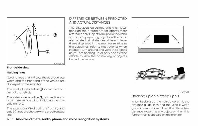
Front-side view
Guiding lines
Guiding lines that indicate the approximatewidth and the front end of the vehicle aredisplayed on the monitor.
The front-of-vehicle line �1 shows the frontpart of the vehicle.
The side-of-vehicle line �2 shows the ap-proximate vehicle width including the out-side mirrors.
The extensions �3 of both the front �1 andside �2 lines are shown with a green dottedline.
DIFFERENCE BETWEEN PREDICTEDAND ACTUAL DISTANCESThe displayed guidelines and their loca-tions on the ground are for approximatereference only. Objects on uphill or downhillsurfaces or projecting objects will be actu-ally located at distances different fromthose displayed in the monitor relative tothe guidelines (refer to illustrations). Whenin doubt, turn around and view the objectsas you are backing up, or park and exit thevehicle to view the positioning of objectsbehind the vehicle.
Backing up on a steep uphillWhen backing up the vehicle up a hill, thedistance guide lines and the vehicle widthguide lines are shown closer than the actualdistance. Note that any object on the hill isfurther than it appears on the monitor.
LHA2652
LHA5178
4-16 Monitor, climate, audio, phone and voice recognition systems
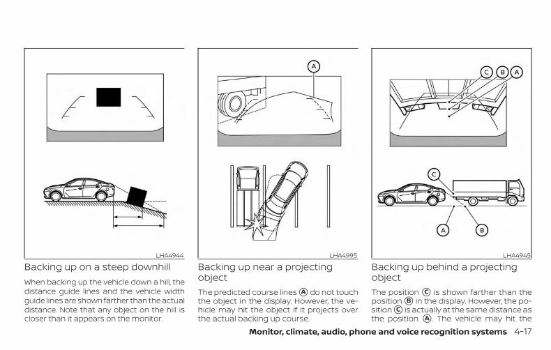
Backing up on a steep downhillWhen backing up the vehicle down a hill, thedistance guide lines and the vehicle widthguide lines are shown farther than the actualdistance. Note that any object on the hill iscloser than it appears on the monitor.
Backing up near a projectingobjectThe predicted course lines �A do not touchthe object in the display. However, the ve-hicle may hit the object if it projects overthe actual backing up course.
Backing up behind a projectingobjectThe position �C is shown farther than theposition �B in the display. However, the po-sition �C is actually at the same distance asthe position �A . The vehicle may hit the
LHA4944 LHA4995 LHA4945
Monitor, climate, audio, phone and voice recognition systems 4-17
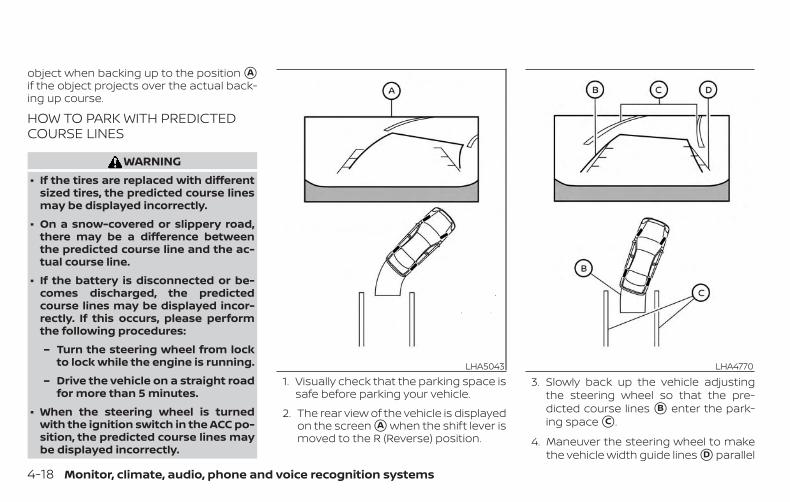
object when backing up to the position �Aif the object projects over the actual back-ing up course.
HOW TO PARK WITH PREDICTEDCOURSE LINES
WARNING∙ If the tires are replaced with different
sized tires, the predicted course linesmay be displayed incorrectly.
∙ On a snow-covered or slippery road,there may be a difference betweenthe predicted course line and the ac-tual course line.
∙ If the battery is disconnected or be-comes discharged, the predictedcourse lines may be displayed incor-rectly. If this occurs, please performthe following procedures:
– Turn the steering wheel from lockto lock while the engine is running.
– Drive the vehicle on a straight roadfor more than 5 minutes.
∙ When the steering wheel is turnedwith the ignition switch in the ACC po-sition, the predicted course lines maybe displayed incorrectly.
1. Visually check that the parking space issafe before parking your vehicle.
2. The rear view of the vehicle is displayedon the screen �A when the shift lever ismoved to the R (Reverse) position.
3. Slowly back up the vehicle adjustingthe steering wheel so that the pre-dicted course lines �B enter the park-ing space �C .
4. Maneuver the steering wheel to makethe vehicle width guide lines �D parallel
LHA5043 LHA4770
4-18 Monitor, climate, audio, phone and voice recognition systems
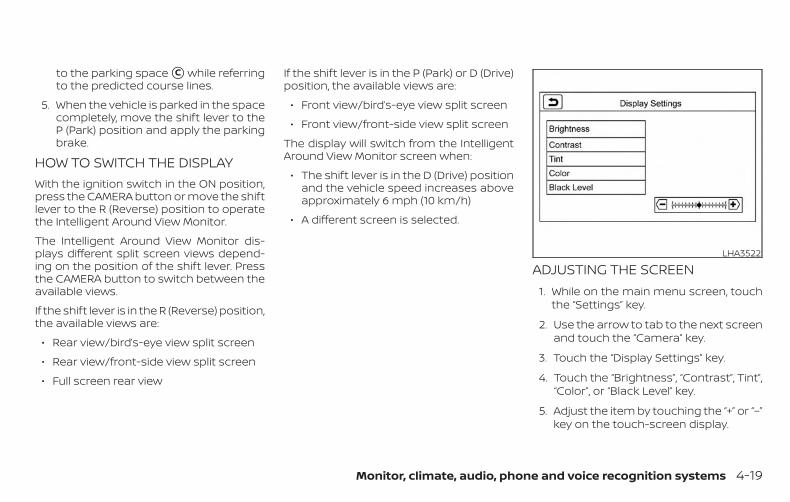
to the parking space �C while referringto the predicted course lines.
5. When the vehicle is parked in the spacecompletely, move the shift lever to theP (Park) position and apply the parkingbrake.
HOW TO SWITCH THE DISPLAYWith the ignition switch in the ON position,press the CAMERA button or move the shiftlever to the R (Reverse) position to operatethe Intelligent Around View Monitor.
The Intelligent Around View Monitor dis-plays different split screen views depend-ing on the position of the shift lever. Pressthe CAMERA button to switch between theavailable views.
If the shift lever is in the R (Reverse) position,the available views are:
∙ Rear view/bird’s-eye view split screen
∙ Rear view/front-side view split screen
∙ Full screen rear view
If the shift lever is in the P (Park) or D (Drive)position, the available views are:
∙ Front view/bird’s-eye view split screen
∙ Front view/front-side view split screen
The display will switch from the IntelligentAround View Monitor screen when:
∙ The shift lever is in the D (Drive) positionand the vehicle speed increases aboveapproximately 6 mph (10 km/h)
∙ A different screen is selected.
ADJUSTING THE SCREEN1. While on the main menu screen, touch
the “Settings” key.
2. Use the arrow to tab to the next screenand touch the “Camera” key.
3. Touch the “Display Settings” key.
4. Touch the “Brightness”, “Contrast”, Tint”,“Color”, or “Black Level” key.
5. Adjust the item by touching the “+” or “–”key on the touch-screen display.
LHA3522
Monitor, climate, audio, phone and voice recognition systems 4-19
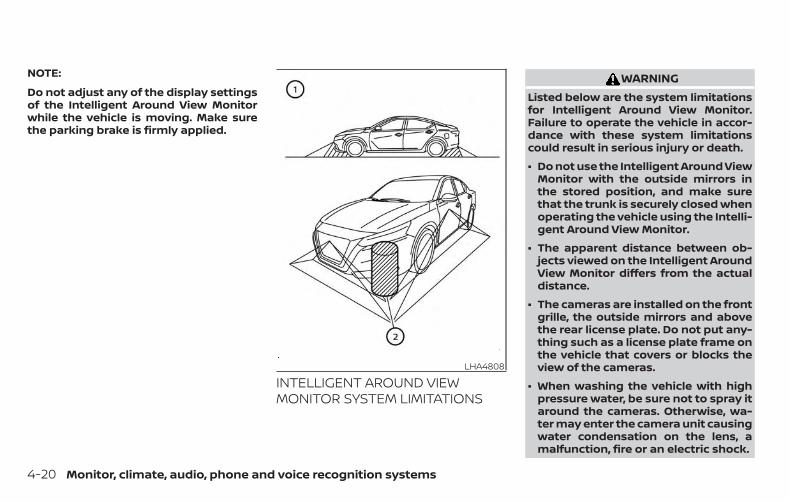
NOTE:
Do not adjust any of the display settingsof the Intelligent Around View Monitorwhile the vehicle is moving. Make surethe parking brake is firmly applied.
INTELLIGENT AROUND VIEWMONITOR SYSTEM LIMITATIONS
WARNINGListed below are the system limitationsfor Intelligent Around View Monitor.Failure to operate the vehicle in accor-dance with these system limitationscould result in serious injury or death.
∙ Do not use the Intelligent Around ViewMonitor with the outside mirrors inthe stored position, and make surethat the trunk is securely closed whenoperating the vehicle using the Intelli-gent Around View Monitor.
∙ The apparent distance between ob-jects viewed on the Intelligent AroundView Monitor differs from the actualdistance.
∙ The cameras are installed on the frontgrille, the outside mirrors and abovethe rear license plate. Do not put any-thing such as a license plate frame onthe vehicle that covers or blocks theview of the cameras.
∙ When washing the vehicle with highpressure water, be sure not to spray itaround the cameras. Otherwise, wa-ter may enter the camera unit causingwater condensation on the lens, amalfunction, fire or an electric shock.
LHA4808
4-20 Monitor, climate, audio, phone and voice recognition systems
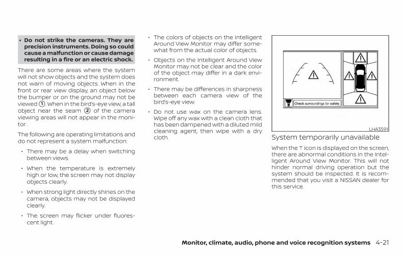
∙ Do not strike the cameras. They areprecision instruments. Doing so couldcause a malfunction or cause damageresulting in a fire or an electric shock.
There are some areas where the systemwill not show objects and the system doesnot warn of moving objects. When in thefront or rear view display, an object belowthe bumper or on the ground may not beviewed �1 . When in the bird’s-eye view, a tallobject near the seam �2 of the cameraviewing areas will not appear in the moni-tor.
The following are operating limitations anddo not represent a system malfunction:
∙ There may be a delay when switchingbetween views.
∙ When the temperature is extremelyhigh or low, the screen may not displayobjects clearly.
∙ When strong light directly shines on thecamera, objects may not be displayedclearly.
∙ The screen may flicker under fluores-cent light.
∙ The colors of objects on the IntelligentAround View Monitor may differ some-what from the actual color of objects.
∙ Objects on the Intelligent Around ViewMonitor may not be clear and the colorof the object may differ in a dark envi-ronment.
∙ There may be differences in sharpnessbetween each camera view of thebird’s-eye view.
∙ Do not use wax on the camera lens.Wipe off any wax with a clean cloth thathas been dampened with a diluted mildcleaning agent, then wipe with a drycloth. System temporarily unavailable
When the “!” icon is displayed on the screen,there are abnormal conditions in the Intel-ligent Around View Monitor. This will nothinder normal driving operation but thesystem should be inspected. It is recom-mended that you visit a NISSAN dealer forthis service.
LHA3591
Monitor, climate, audio, phone and voice recognition systems 4-21
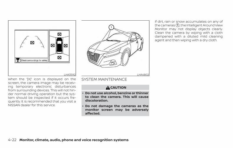
When the “[X]” icon is displayed on thescreen, the camera image may be receiv-ing temporary electronic disturbancesfrom surrounding devices. This will not hin-der normal driving operation but the sys-tem should be inspected if it occurs fre-quently. It is recommended that you visit aNISSAN dealer for this service.
SYSTEM MAINTENANCE
CAUTION∙ Do not use alcohol, benzine or thinner
to clean the camera. This will causediscoloration.
∙ Do not damage the cameras as themonitor screen may be adverselyaffected.
If dirt, rain or snow accumulates on any ofthe cameras �1 , the Intelligent Around ViewMonitor may not display objects clearly.Clean the camera by wiping with a clothdampened with a diluted mild cleaningagent and then wiping with a dry cloth.
LHA3592 LHA4802
4-22 Monitor, climate, audio, phone and voice recognition systems
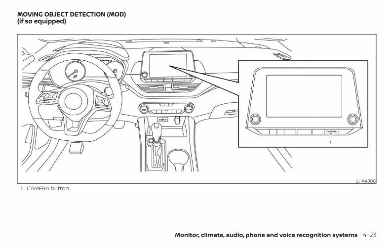
1. CAMERA buttonLHA4800
MOVING OBJECT DETECTION (MOD)(if so equipped)
Monitor, climate, audio, phone and voice recognition systems 4-23
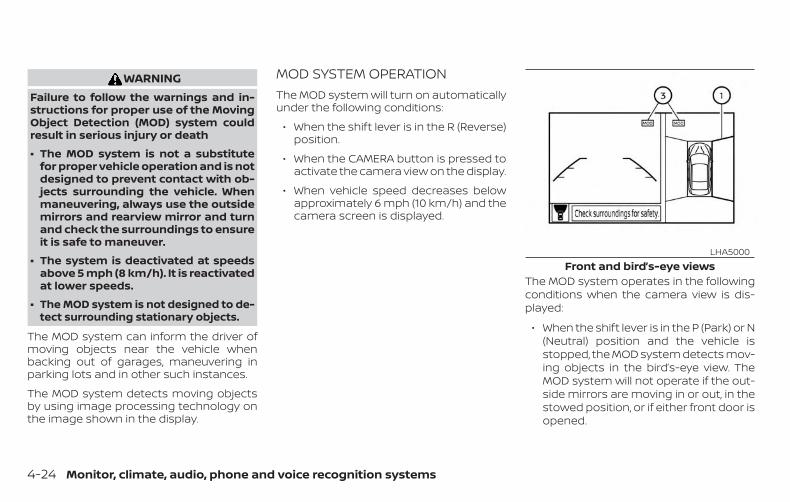
WARNINGFailure to follow the warnings and in-structions for proper use of the MovingObject Detection (MOD) system couldresult in serious injury or death
∙ The MOD system is not a substitutefor proper vehicle operation and is notdesigned to prevent contact with ob-jects surrounding the vehicle. Whenmaneuvering, always use the outsidemirrors and rearview mirror and turnand check the surroundings to ensureit is safe to maneuver.
∙ The system is deactivated at speedsabove 5 mph (8 km/h). It is reactivatedat lower speeds.
∙ The MOD system is not designed to de-tect surrounding stationary objects.
The MOD system can inform the driver ofmoving objects near the vehicle whenbacking out of garages, maneuvering inparking lots and in other such instances.
The MOD system detects moving objectsby using image processing technology onthe image shown in the display.
MOD SYSTEM OPERATIONThe MOD system will turn on automaticallyunder the following conditions:
∙ When the shift lever is in the R (Reverse)position.
∙ When the CAMERA button is pressed toactivate the camera view on the display.
∙ When vehicle speed decreases belowapproximately 6 mph (10 km/h) and thecamera screen is displayed.
The MOD system operates in the followingconditions when the camera view is dis-played:
∙ When the shift lever is in the P (Park) or N(Neutral) position and the vehicle isstopped, the MOD system detects mov-ing objects in the bird’s-eye view. TheMOD system will not operate if the out-side mirrors are moving in or out, in thestowed position, or if either front door isopened.
Front and bird’s-eye viewsLHA5000
4-24 Monitor, climate, audio, phone and voice recognition systems
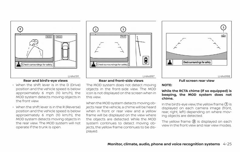
∙ When the shift lever is in the D (Drive)position and the vehicle speed is belowapproximately 6 mph (10 km/h), theMOD system detects moving objects inthe front view.
∙ When the shift lever is in the R (Reverse)position and the vehicle speed is belowapproximately 6 mph (10 km/h), theMOD system detects moving objects inthe rear view. The MOD system will notoperate if the trunk is open.
The MOD system does not detect movingobjects in the front-side view. The MODicon is not displayed on the screen when inthis view.
When the MOD system detects moving ob-jects near the vehicle, a chime will be heardwhen in front or rear view and a yellowframe will be displayed on the view wherethe objects are detected. While the MODsystem continues to detect moving ob-jects, the yellow frame continues to be dis-played.
NOTE:
While the RCTA chime (if so equipped) isbeeping, the MOD system does notchime.
In the bird’s-eye view, the yellow frame �1 isdisplayed on each camera image (front,rear, right, left) depending on where mov-ing objects are detected.
The yellow frame �2 is displayed on eachview in the front view and rear view modes.
Rear and bird’s-eye viewsLHA4191
Rear and front-side viewsLHA4997
Full screen rear viewLHA4998
Monitor, climate, audio, phone and voice recognition systems 4-25
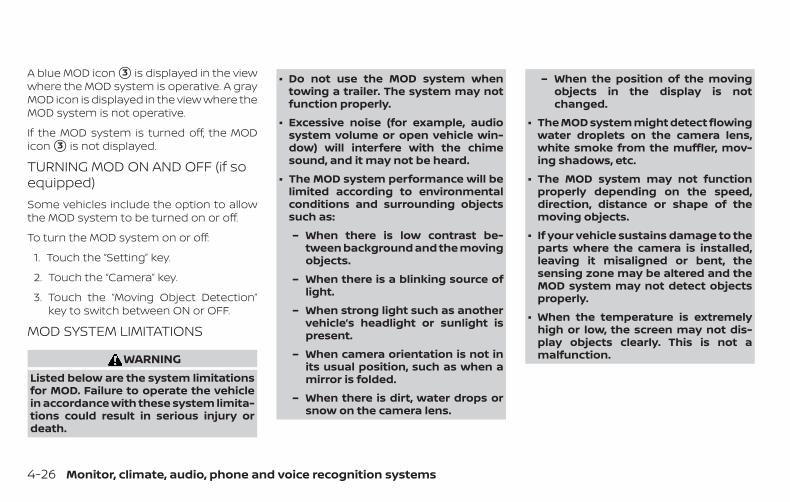
A blue MOD icon �3 is displayed in the viewwhere the MOD system is operative. A grayMOD icon is displayed in the view where theMOD system is not operative.
If the MOD system is turned off, the MODicon �3 is not displayed.
TURNING MOD ON AND OFF (if soequipped)Some vehicles include the option to allowthe MOD system to be turned on or off.
To turn the MOD system on or off:
1. Touch the “Setting” key.
2. Touch the “Camera” key.
3. Touch the “Moving Object Detection”key to switch between ON or OFF.
MOD SYSTEM LIMITATIONS
WARNINGListed below are the system limitationsfor MOD. Failure to operate the vehiclein accordance with these system limita-tions could result in serious injury ordeath.
∙ Do not use the MOD system whentowing a trailer. The system may notfunction properly.
∙ Excessive noise (for example, audiosystem volume or open vehicle win-dow) will interfere with the chimesound, and it may not be heard.
∙ The MOD system performance will belimited according to environmentalconditions and surrounding objectssuch as:
– When there is low contrast be-tween background and the movingobjects.
– When there is a blinking source oflight.
– When strong light such as anothervehicle’s headlight or sunlight ispresent.
– When camera orientation is not inits usual position, such as when amirror is folded.
– When there is dirt, water drops orsnow on the camera lens.
– When the position of the movingobjects in the display is notchanged.
∙ The MOD system might detect flowingwater droplets on the camera lens,white smoke from the muffler, mov-ing shadows, etc.
∙ The MOD system may not functionproperly depending on the speed,direction, distance or shape of themoving objects.
∙ If your vehicle sustains damage to theparts where the camera is installed,leaving it misaligned or bent, thesensing zone may be altered and theMOD system may not detect objectsproperly.
∙ When the temperature is extremelyhigh or low, the screen may not dis-play objects clearly. This is not amalfunction.
4-26 Monitor, climate, audio, phone and voice recognition systems
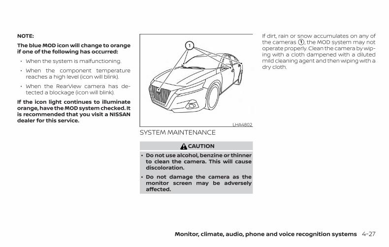
NOTE:
The blue MOD icon will change to orangeif one of the following has occurred:
∙ When the system is malfunctioning.
∙ When the component temperaturereaches a high level (icon will blink).
∙ When the RearView camera has de-tected a blockage (icon will blink).
If the icon light continues to illuminateorange, have the MOD system checked. Itis recommended that you visit a NISSANdealer for this service.
SYSTEM MAINTENANCE
CAUTION∙ Do not use alcohol, benzine or thinner
to clean the camera. This will causediscoloration.
∙ Do not damage the camera as themonitor screen may be adverselyaffected.
If dirt, rain or snow accumulates on any ofthe cameras �1 , the MOD system may notoperate properly. Clean the camera by wip-ing with a cloth dampened with a dilutedmild cleaning agent and then wiping with adry cloth.
LHA4802
Monitor, climate, audio, phone and voice recognition systems 4-27
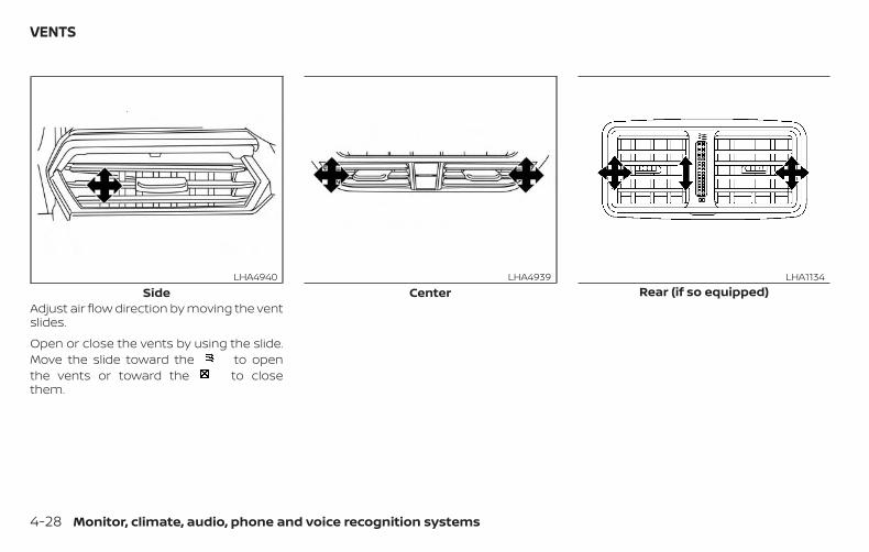
Adjust air flow direction by moving the ventslides.
Open or close the vents by using the slide.Move the slide toward the to openthe vents or toward the to closethem.
SideLHA4940
CenterLHA4939
Rear (if so equipped)LHA1134
VENTS
4-28 Monitor, climate, audio, phone and voice recognition systems
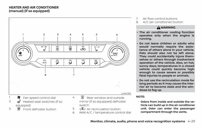
1. Fan speed control dial2. Heated seat switches (if so
equipped)3. Front defroster button
4. Rear window and outsidemirror (if so equipped) defrosterswitch
5. Air recirculation button6. MAX A/C / temperature control dial
7. Air flow control buttons8. A/C (air conditioner) button
WARNING∙ The air conditioner cooling function
operates only when the engine isrunning.
∙ Do not leave children or adults whowould normally require the assis-tance of others alone in your vehicle.Pets should also not be left alone.They could accidentally injure them-selves or others through inadvertentoperation of the vehicle. Also, on hot,sunny days, temperatures in a closedvehicle could quickly become highenough to cause severe or possiblyfatal injuries to people or animals.
∙ Do not use the recirculation mode forlong periods as it may cause the inte-rior air to become stale and the win-dows to fog up.
NOTE:
∙ Odors from inside and outside the ve-hicle can build up in the air conditionerunit. Odor can enter the passengercompartment through the vents.
LHA4783
HEATER AND AIR CONDITIONER(manual) (if so equipped)
Monitor, climate, audio, phone and voice recognition systems 4-29
∙ When parking, set the heater and airconditioner controls to turn off air re-circulation to allow fresh air into thepassenger compartment. This shouldhelp reduce odors inside the vehicle.
CONTROLSFan speed control dialThe fan speed control dial turns thefan on and off, and controls fan speed.
Air flow control buttonsThe air flow control buttons allow you toselect the air flow outlets.
— Air flows from center and sidevents.
— Air flows from center and sidevents and foot outlets.
— Air flows mainly from footoutlets.
— Air flows from defroster outletsand foot outlets.
— Air flows mainly from defrosteroutlets.
Temperature control dialThe temperature control dial allows you toadjust the temperature of the outlet air. Tolower the temperature, turn the dial to theleft. To increase the temperature, turn thedial to the right.
Turn the dial to the MAX A/C position formaximum cooling. Air will flow from centerand side vents.
Air recirculation buttonOn position (Indicator light on):Interior air is recirculated inside the vehicle.
Press the button to the on positionwhen:
∙ driving on a dusty road.
∙ to prevent traffic fumes from enteringpassenger compartment.
∙ for maximum cooling when using theair conditioner.
Off position (Indicator light off):Outside air is drawn into the passengercompartment and distributed through theselected outlet.
Use the off position for normal heater or airconditioner operation.
A/C (air conditioner) button
Start the engine, turn the fan speedcontrol dial to the desired position andpress the button to turn on the airconditioner. To turn off the air conditioner,press the button again.The air conditioner cooling function op-erates only when the engine is running.
Rear window and outside mirror(if so equipped) defroster switchFor additional information, refer to “Rearwindow and outside mirror (if so equipped)defroster switch” in the “Instruments andcontrols” section of this manual.
Heated seat switches (if soequipped)For additional information, refer to “Heatedseat switches” in the “Instruments and con-trols” section of this manual.
HEATER OPERATIONHeatingThis mode is used to direct heated air tothe foot outlets. Some air also flows fromthe defrost outlets and the side vent out-lets.
4-30 Monitor, climate, audio, phone and voice recognition systems
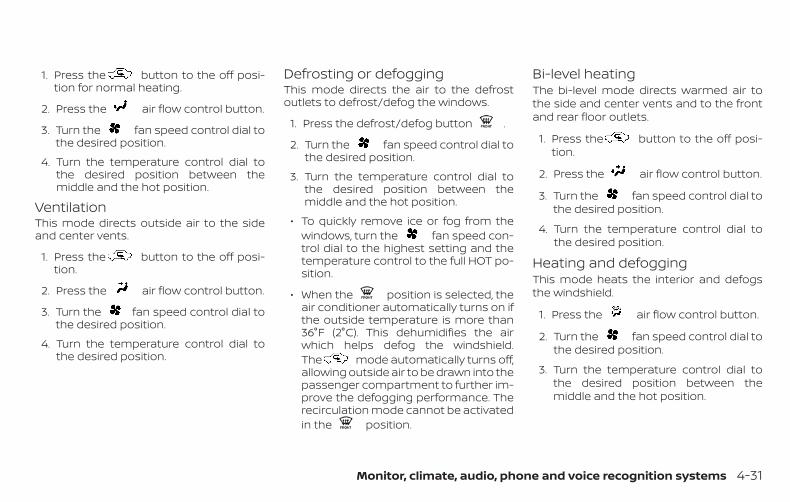
1. Press the button to the off posi-tion for normal heating.
2. Press the air flow control button.
3. Turn the fan speed control dial tothe desired position.
4. Turn the temperature control dial tothe desired position between themiddle and the hot position.
VentilationThis mode directs outside air to the sideand center vents.
1. Press the button to the off posi-tion.
2. Press the air flow control button.
3. Turn the fan speed control dial tothe desired position.
4. Turn the temperature control dial tothe desired position.
Defrosting or defoggingThis mode directs the air to the defrostoutlets to defrost/defog the windows.
1. Press the defrost/defog button .
2. Turn the fan speed control dial tothe desired position.
3. Turn the temperature control dial tothe desired position between themiddle and the hot position.
∙ To quickly remove ice or fog from thewindows, turn the fan speed con-trol dial to the highest setting and thetemperature control to the full HOT po-sition.
∙ When the position is selected, theair conditioner automatically turns on ifthe outside temperature is more than36°F (2°C). This dehumidifies the airwhich helps defog the windshield.The mode automatically turns off,allowing outside air to be drawn into thepassenger compartment to further im-prove the defogging performance. Therecirculation mode cannot be activatedin the position.
Bi-level heatingThe bi-level mode directs warmed air tothe side and center vents and to the frontand rear floor outlets.
1. Press the button to the off posi-tion.
2. Press the air flow control button.
3. Turn the fan speed control dial tothe desired position.
4. Turn the temperature control dial tothe desired position.
Heating and defoggingThis mode heats the interior and defogsthe windshield.
1. Press the air flow control button.
2. Turn the fan speed control dial tothe desired position.
3. Turn the temperature control dial tothe desired position between themiddle and the hot position.
Monitor, climate, audio, phone and voice recognition systems 4-31
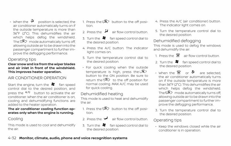
∙ When the position is selected, theair conditioner automatically turns on ifthe outside temperature is more than36°F (2°C). This dehumidifies the airwhich helps defog the windshield.The mode automatically turns off,allowing outside air to be drawn into thepassenger compartment to further im-prove the defogging performance.
Operating tipsClear snow and ice from the wiper bladesand air inlet in front of the windshield.This improves heater operation.
AIR CONDITIONER OPERATION
Start the engine, turn the fan speedcontrol dial to the desired position, andpress the button to activate the airconditioner. When the air conditioner is on,cooling and dehumidifying functions areadded to the heater operation.The air conditioner cooling function op-erates only when the engine is running.
CoolingThis mode is used to cool and dehumidifythe air.
1. Press the button to the off posi-tion.
2. Press the air flow control button.
3. Turn the fan speed control dial tothe desired position.
4. Press the A/C button. The indicatorlight comes on.
5. Turn the temperature control dial tothe desired position.
∙ For quick cooling when the outsidetemperature is high, press thebutton to the ON position. Be sure toreturn the to the off position fornormal cooling. MAX A/C may be usedfor quick cooling.
Dehumidified heatingThis mode is used to heat and dehumidifythe air.
1. Press the button to the off posi-tion.
2. Press the air flow control button.
3. Turn the fan speed control dial tothe desired position.
4. Press the A/C (air conditioner) button.The indicator light comes on.
5. Turn the temperature control dial tothe desired position.
Dehumidified defoggingThis mode is used to defog the windowsand dehumidify the air.
1. Press the air flow control button.
2. Turn the fan speed control dial tothe desired position.
∙ When the or are selected,the air conditioner automatically turnson if the outside temperature is morethan 36°F (2°C). This dehumidifies the airwhich helps defog the windshield.The mode automatically turns off,allowing outside air to be drawn into thepassenger compartment to further im-prove the defogging performance.
3. Turn the temperature control dial tothe desired position.
Operating tips∙ Keep the windows closed while the air
conditioner is in operation.
4-32 Monitor, climate, audio, phone and voice recognition systems
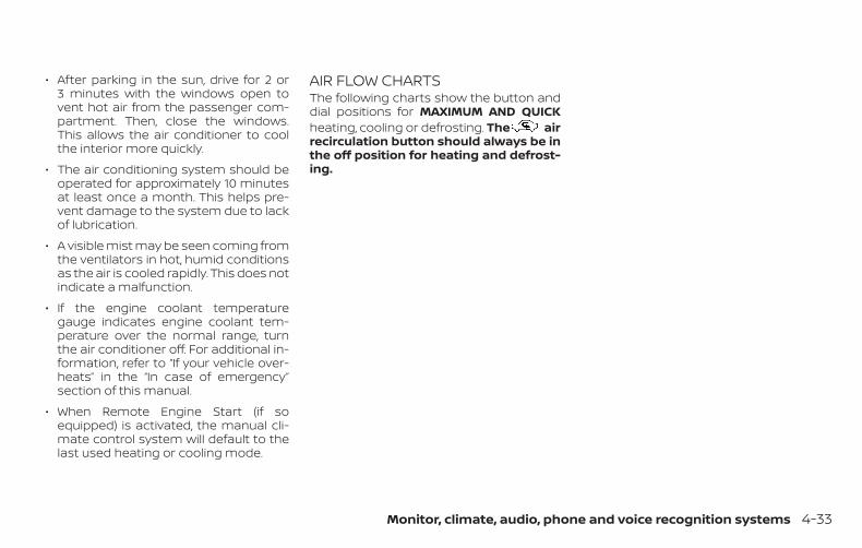
∙ After parking in the sun, drive for 2 or3 minutes with the windows open tovent hot air from the passenger com-partment. Then, close the windows.This allows the air conditioner to coolthe interior more quickly.
∙ The air conditioning system should beoperated for approximately 10 minutesat least once a month. This helps pre-vent damage to the system due to lackof lubrication.
∙ A visible mist may be seen coming fromthe ventilators in hot, humid conditionsas the air is cooled rapidly. This does notindicate a malfunction.
∙ If the engine coolant temperaturegauge indicates engine coolant tem-perature over the normal range, turnthe air conditioner off. For additional in-formation, refer to “If your vehicle over-heats” in the “In case of emergency”section of this manual.
∙ When Remote Engine Start (if soequipped) is activated, the manual cli-mate control system will default to thelast used heating or cooling mode.
AIR FLOW CHARTSThe following charts show the button anddial positions for MAXIMUM AND QUICKheating, cooling or defrosting. The airrecirculation button should always be inthe off position for heating and defrost-ing.
Monitor, climate, audio, phone and voice recognition systems 4-33
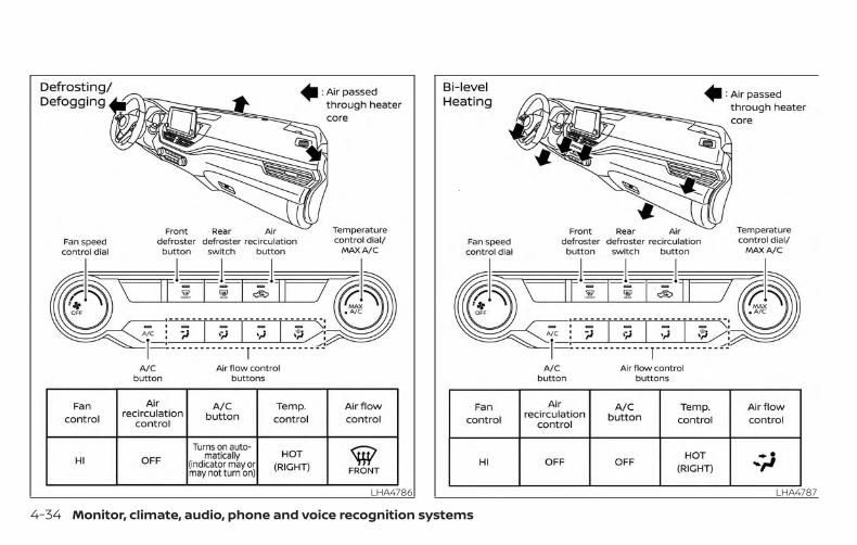
LHA4786 LHA4787
4-34 Monitor, climate, audio, phone and voice recognition systems
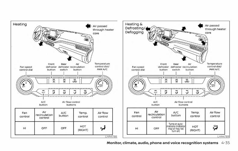
LHA4788 LHA4789
Monitor, climate, audio, phone and voice recognition systems 4-35
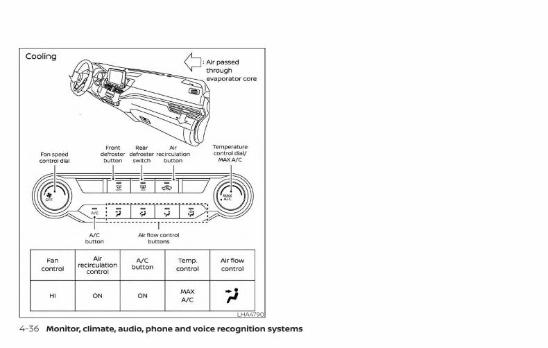
LHA4790
4-36 Monitor, climate, audio, phone and voice recognition systems
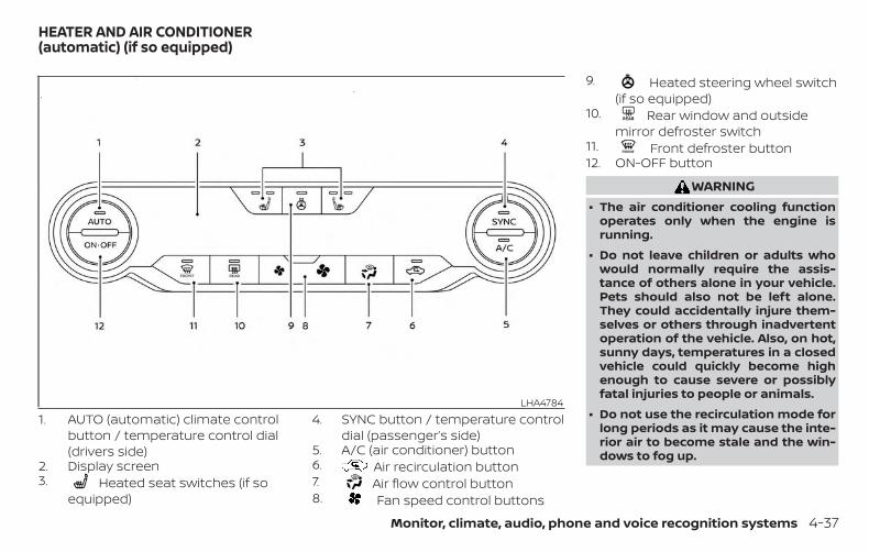
1. AUTO (automatic) climate controlbutton / temperature control dial(drivers side)
2. Display screen3. Heated seat switches (if so
equipped)
4. SYNC button / temperature controldial (passenger’s side)
5. A/C (air conditioner) button6. Air recirculation button7. Air flow control button8. Fan speed control buttons
9. Heated steering wheel switch(if so equipped)
10. Rear window and outsidemirror defroster switch
11. Front defroster button12. ON-OFF button
WARNING∙ The air conditioner cooling function
operates only when the engine isrunning.
∙ Do not leave children or adults whowould normally require the assis-tance of others alone in your vehicle.Pets should also not be left alone.They could accidentally injure them-selves or others through inadvertentoperation of the vehicle. Also, on hot,sunny days, temperatures in a closedvehicle could quickly become highenough to cause severe or possiblyfatal injuries to people or animals.
∙ Do not use the recirculation mode forlong periods as it may cause the inte-rior air to become stale and the win-dows to fog up.
LHA4784
HEATER AND AIR CONDITIONER(automatic) (if so equipped)
Monitor, climate, audio, phone and voice recognition systems 4-37
Start the engine and operate the controlsto activate the air conditioner.
NOTE:
∙ Odors from inside and outside the ve-hicle can build up in the air condi-tioner unit. Odor can enter the pas-senger compartment through thevents.
∙ When parking, set the heater and airconditioner controls to turn off air re-circulation to allow fresh air into thepassenger compartment. This shouldhelp reduce odors inside the vehicle.
AUTOMATIC OPERATIONCooling and/or dehumidifiedheating (AUTO)This mode may be used all year round asthe system automatically works to keep aconstant temperature. Air flow distribution,air intake control, and fan speed are alsocontrolled automatically.
1. Press the AUTO button on.
2. Turn the temperature control dial tothe left or right to set the desired tem-perature.
∙ Adjust the temperature display toabout 75°F (24°C) for normal operation.
∙ The temperature of the passengercompartment will be maintained auto-matically. Air flow distribution, air intakecontrol and fan speed are also con-trolled automatically.
∙ A visible mist may be seen coming fromthe vents in hot, humid conditions asthe air is cooled rapidly. This does notindicate a malfunction.
3. You can individually set driver’s andfront passenger’s side temperature us-ing each temperature control dial. Tosynchronize the driver’s and front pas-senger’s temperature settings, pressthe SYNC button.
Heating (A/C OFF)The air conditioner does not activate. Whenyou need to heat only, use this mode.
1. Press the AUTO button.
2. Turn the temperature control dial to setthe desired temperature.
∙ The temperature of the passengercompartment will be maintained auto-matically. Air flow distribution and fanspeed are also controlled automatically.
∙ Do not set the temperature lower thanthe outside air temperature. Otherwise,the system may not work properly.
∙ Not recommended if windows fog up.
Dehumidified defrosting ordefogging
1. Press the front defroster buttonon.
2. Turn the temperature control dial to setthe desired temperature.
∙ To quickly remove ice from the outsideof the windows, use the fan speedcontrol buttons to set the fan speed tomaximum.
∙ As soon as possible after the wind-shield is clean, press the AUTO button toreturn to the automatic mode.
∙ When the front defroster button ispressed, the air conditioner will auto-matically be turned on at outside tem-peratures above 36°F (2°C). The air recir-culate mode automatically turns off,allowing outside air to be drawn into thepassenger compartment to further im-prove the defogging performance.
4-38 Monitor, climate, audio, phone and voice recognition systems
Remote Engine Start withIntelligent Climate Control (if soequipped)Vehicles equipped with automatic climatecontrols and Remote Engine Start functionmay go into automatic heating or coolingmode when Remote Engine Start is acti-vated depending on outside and cabintemperatures. During this period, the cli-mate control display and buttons will beinoperable until the ignition switch isturned on. In Remote Engine Start defrost-ing mode, the rear window defroster andheated steering wheel (if so equipped) maybe activated automatically.
MANUAL OPERATIONFan speed control buttons
Press the fan speed control buttonsto manually control the fan speed.Press the AUTO button to return to auto-matic control of the fan speed.
Temperature control dialThe temperature control dial allows you toadjust the temperature of the outlet air. Tolower the temperature, turn the dial to theleft. To increase the temperature, turn the
dial to the right. Temperature can be ad-justed on the driver’s and passenger’s side.
Air recirculationPress the air recirculation button torecirculate interior air inside the vehicle.The indicator light on the button willcome on.The air recirculation cannot be activatedwhen the air conditioner is in thefront defrosting mode.When the outside temperature exceeds70°F (21°C), the air conditioning system maydefault to air recirculation mode automati-cally to reduce overall power consumption.To exit air recirculation mode, deselect theair recirculation button (indicator light willturn off) to enter fresh air mode.
Automatic intake air controlIn the AUTO mode, the intake air will becontrolled automatically. To manually con-trol the intake air, press the air recir-culation button. To return to the automaticcontrol mode, press and hold the airrecirculation button for about 2 seconds.The indicator light will flash twice, and thenthe intake air will be controlled automati-cally.
A/C (air conditioner) button
Start the engine, press the fan speedcontrol buttons to the desired position andpress the button to turn on the airconditioner. To turn off the air conditioner,press the button again.The air conditioner cooling function op-erates only when the engine is running.
Air flow control
Pressing the button manually con-trols air flow and selects the air outlet:
— Air flows from center and sidevents.
— Air flows from center and sidevents and foot outlets.
— Air flows mainly from footoutlets.
— Air flows from defroster andfoot outlets.
Synchronize climate settingsPress the SYNC button to synchronize cli-mate settings. The sync indicator will turnon.
Pressing SYNC will synchronize driver’s andfront passenger’s climate settings.
Monitor, climate, audio, phone and voice recognition systems 4-39
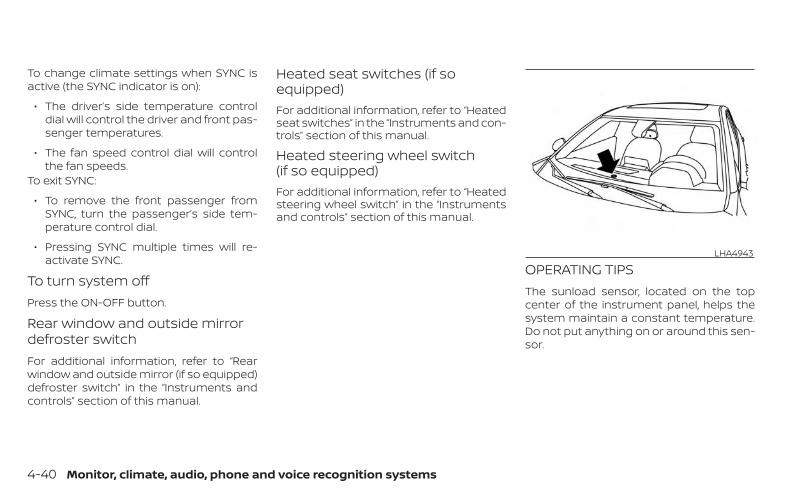
To change climate settings when SYNC isactive (the SYNC indicator is on):
∙ The driver’s side temperature controldial will control the driver and front pas-senger temperatures.
∙ The fan speed control dial will controlthe fan speeds.
To exit SYNC:
∙ To remove the front passenger fromSYNC, turn the passenger’s side tem-perature control dial.
∙ Pressing SYNC multiple times will re-activate SYNC.
To turn system offPress the ON-OFF button.
Rear window and outside mirrordefroster switchFor additional information, refer to “Rearwindow and outside mirror (if so equipped)defroster switch” in the “Instruments andcontrols” section of this manual.
Heated seat switches (if soequipped)For additional information, refer to “Heatedseat switches” in the “Instruments and con-trols” section of this manual.
Heated steering wheel switch(if so equipped)For additional information, refer to “Heatedsteering wheel switch” in the “Instrumentsand controls” section of this manual.
OPERATING TIPSThe sunload sensor, located on the topcenter of the instrument panel, helps thesystem maintain a constant temperature.Do not put anything on or around this sen-sor.
LHA4943
4-40 Monitor, climate, audio, phone and voice recognition systems
∙ When the climate system is in auto-matic operation and the engine coolanttemperature and outside air tempera-ture are low, the air flow outlet may de-fault to defroster mode for a maximumof 2 minutes 30 seconds. This is not amalfunction. After the engine coolanttemperature warms up, the air flow out-let will return to foot mode and opera-tion will continue normally.
∙ When the outside and interior cabintemperatures are moderate to high, theintake setting may default to turn off airrecirculation to allow fresh air into thepassenger compartment. You may no-tice air flow from the foot mode, bi-levelmode, or side demist vent outlets for amaximum of 15 seconds. This may oc-cur when the previous climate settingwas turned off. This is not a malfunction.After the initial warm air is expelled, theintake will return to automatic control,the air flow outlet will return to previoussettings, and operation will continuenormally. To exit, press any climate con-trol button.
∙ Keep the moonroof (if so equipped)closed while the air conditioner is in op-eration.
∙ If you feel that the air flow mode youhave selected and the outlets the air iscoming out do not match, selectthe mode.
∙ When you change the air flow mode,you may feel air flow from the foot out-lets for just a moment. This is not amalfunction.
The air conditioner system in your NISSANvehicle is charged with a refrigerant de-signed with the environment in mind.This refrigerant does not harm theearth’s ozone layer.
Special charging equipment and lubricantis required when servicing your NISSAN airconditioner. Using improper refrigerants orlubricants will cause severe damage toyour air conditioner system. For additionalinformation, refer to “Air conditioner sys-tem refrigerant and oil recommendations”in the “Technical and consumer informa-tion” section of this manual.
It is recommended that you visit a NISSANdealer to service your “environmentallyfriendly” air conditioner system.
WARNINGThe air conditioner system contains re-frigerant under high pressure. To avoidpersonal injury, any air conditioner ser-vice should be done only by an experi-enced technician with proper equipment.
SERVICING AIR CONDITIONER
Monitor, climate, audio, phone and voice recognition systems 4-41
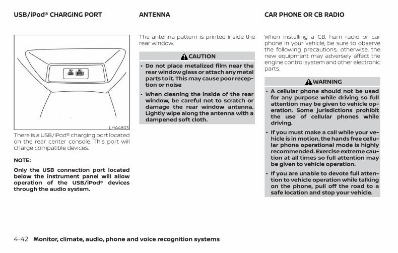
There is a USB/iPod® charging port locatedon the rear center console. This port willcharge compatible devices.
NOTE:
Only the USB connection port locatedbelow the instrument panel will allowoperation of the USB/iPod® devicesthrough the audio system.
The antenna pattern is printed inside therear window.
CAUTION∙ Do not place metalized film near the
rear window glass or attach any metalparts to it. This may cause poor recep-tion or noise
∙ When cleaning the inside of the rearwindow, be careful not to scratch ordamage the rear window antenna.Lightly wipe along the antenna with adampened soft cloth.
When installing a CB, ham radio or carphone in your vehicle, be sure to observethe following precautions; otherwise, thenew equipment may adversely affect theengine control system and other electronicparts.
WARNING∙ A cellular phone should not be used
for any purpose while driving so fullattention may be given to vehicle op-eration. Some jurisdictions prohibitthe use of cellular phones whiledriving.
∙ If you must make a call while your ve-hicle is in motion, the hands free cellu-lar phone operational mode is highlyrecommended. Exercise extreme cau-tion at all times so full attention maybe given to vehicle operation.
∙ If you are unable to devote full atten-tion to vehicle operation while talkingon the phone, pull off the road to asafe location and stop your vehicle.
LHA4803
USB/iPod® CHARGING PORT ANTENNA CAR PHONE OR CB RADIO
4-42 Monitor, climate, audio, phone and voice recognition systems
CAUTION∙ Keep the antenna as far away as pos-
sible from the electronic controlmodules.
∙ Keep the antenna wire more than 8 in(20 cm) away from the electronic con-trol system harnesses. Do not routethe antenna wire next to any harness.
∙ Adjust the antenna standing-waveratio as recommended by themanufacturer.
∙ Connect the ground wire from the CBradio chassis to the body.
∙ For additional information, it is rec-ommended that you visit a NISSANdealer for servicing.
Monitor, climate, audio, phone and voice recognition systems 4-43
5 Starting and driving
Precautions when starting and driving . . . . . . . . . . 5-4Exhaust gas (carbon monoxide) . . . . . . . . . . . . . . 5-4Three-way catalyst . . . . . . . . . . . . . . . . . . . . . . . . . . . 5-4Tire Pressure Monitoring System(TPMS). . . . . . . . . . . . . . . . . . . . . . . . . . . . . . . . . . . . . . . . 5-5Avoiding collision and rollover . . . . . . . . . . . . . . . . 5-9Off-road recovery . . . . . . . . . . . . . . . . . . . . . . . . . . . . 5-9Rapid air pressure loss . . . . . . . . . . . . . . . . . . . . . . . 5-9Drinking alcohol/drugs and driving . . . . . . . . . . 5-10Driving safety precautions . . . . . . . . . . . . . . . . . . . .5-11
Push-button ignition switch . . . . . . . . . . . . . . . . . . . . 5-13Operating range. . . . . . . . . . . . . . . . . . . . . . . . . . . . . 5-14Push-button ignition switch positions . . . . . . . 5-14Emergency engine shut off . . . . . . . . . . . . . . . . . . 5-15NISSAN Intelligent Key® batterydischarge . . . . . . . . . . . . . . . . . . . . . . . . . . . . . . . . . . . 5-15NISSAN Vehicle Immobilizer System . . . . . . . . . 5-16
Before starting the engine. . . . . . . . . . . . . . . . . . . . . . 5-16Starting the engine . . . . . . . . . . . . . . . . . . . . . . . . . . . . . 5-17
Remote Engine Start (if so equipped) . . . . . . . . 5-18Driving the vehicle . . . . . . . . . . . . . . . . . . . . . . . . . . . . . . 5-18
Continuously Variable Transmission(CVT) . . . . . . . . . . . . . . . . . . . . . . . . . . . . . . . . . . . . . . . . 5-18
Parking brake . . . . . . . . . . . . . . . . . . . . . . . . . . . . . . . . . . 5-25Pedal type . . . . . . . . . . . . . . . . . . . . . . . . . . . . . . . . . . . 5-26Switch type (models with electronicparking brake system). . . . . . . . . . . . . . . . . . . . . . . 5-26
Automatic brake hold (if so equipped) . . . . . . . . . . 5-28How to activate/deactivate theautomatic brake hold function . . . . . . . . . . . . . . 5-29How to use the automatic brake holdfunction . . . . . . . . . . . . . . . . . . . . . . . . . . . . . . . . . . . . . 5-30
Traffic Sign Recognition (TSR) (if so equipped) . . . 5-31System operation . . . . . . . . . . . . . . . . . . . . . . . . . . . 5-32Turning the Traffic Sign Recognition(TSR) system on and off . . . . . . . . . . . . . . . . . . . . . 5-33System temporarily unavailable . . . . . . . . . . . . . 5-33System malfunction . . . . . . . . . . . . . . . . . . . . . . . . . 5-33System maintenance. . . . . . . . . . . . . . . . . . . . . . . . 5-34
Lane Departure Warning (LDW)(if so equipped) . . . . . . . . . . . . . . . . . . . . . . . . . . . . . . . . . 5-34
LDW system operation . . . . . . . . . . . . . . . . . . . . . . 5-35How to enable/disable the LDW system . . . . . 5-36LDW system limitations. . . . . . . . . . . . . . . . . . . . . . 5-36System temporarily unavailable . . . . . . . . . . . . . 5-37System malfunction . . . . . . . . . . . . . . . . . . . . . . . . . 5-38
System maintenance. . . . . . . . . . . . . . . . . . . . . . . . 5-38Intelligent Lane Intervention (I-LI)(if so equipped) . . . . . . . . . . . . . . . . . . . . . . . . . . . . . . . . . 5-39
I-LI system operation . . . . . . . . . . . . . . . . . . . . . . . .5-40How to enable/disable the I-LI system. . . . . . . 5-41I-LI system limitations . . . . . . . . . . . . . . . . . . . . . . . 5-42System temporarily unavailable . . . . . . . . . . . . . 5-43System malfunction . . . . . . . . . . . . . . . . . . . . . . . . . 5-44System maintenance. . . . . . . . . . . . . . . . . . . . . . . . 5-44
Blind Spot Warning (BSW) (if so equipped) . . . . . . . 5-45BSW system operation . . . . . . . . . . . . . . . . . . . . . . 5-46How to enable/disable the BSW system . . . . .5-48BSW system limitations. . . . . . . . . . . . . . . . . . . . . .5-48BSW driving situations . . . . . . . . . . . . . . . . . . . . . . . 5-49System temporarily unavailable . . . . . . . . . . . . . 5-53System maintenance. . . . . . . . . . . . . . . . . . . . . . . . 5-54
Rear Cross Traffic Alert (RCTA) (if so equipped) . . 5-55RCTA system operation. . . . . . . . . . . . . . . . . . . . . . 5-56How to enable/disable the RCTAsystem . . . . . . . . . . . . . . . . . . . . . . . . . . . . . . . . . . . . . .5-58RCTA system limitations . . . . . . . . . . . . . . . . . . . . . 5-59System temporarily unavailable . . . . . . . . . . . . . 5-62System maintenance. . . . . . . . . . . . . . . . . . . . . . . . 5-62
Cruise control (if so equipped) . . . . . . . . . . . . . . . . . . 5-64
Precautions on cruise control. . . . . . . . . . . . . . . . 5-64Cruise control operations. . . . . . . . . . . . . . . . . . . . 5-65
Intelligent Cruise Control (ICC) (for vehicleswithout ProPILOT Assist) (if so equipped). . . . . . . . 5-67
How to select the cruise control mode . . . . . . 5-69Vehicle-to-vehicle distance controlmode . . . . . . . . . . . . . . . . . . . . . . . . . . . . . . . . . . . . . . . 5-69Vehicle-to-vehicle distance controlmode operation . . . . . . . . . . . . . . . . . . . . . . . . . . . . . 5-71Vehicle-to-vehicle distance controlmode switches. . . . . . . . . . . . . . . . . . . . . . . . . . . . . . 5-72Vehicle-to-vehicle distance controlmode limitations . . . . . . . . . . . . . . . . . . . . . . . . . . . . 5-79System temporarily unavailable . . . . . . . . . . . . . 5-83System maintenance. . . . . . . . . . . . . . . . . . . . . . . .5-85Conventional (fixed speed) cruisecontrol mode. . . . . . . . . . . . . . . . . . . . . . . . . . . . . . . .5-86
ProPILOT Assist (if so equipped). . . . . . . . . . . . . . . . . 5-91ProPILOT Assist system operation . . . . . . . . . . . 5-93Turning the conventional (fixed speed)cruise control mode on. . . . . . . . . . . . . . . . . . . . . . 5-96Operating ProPILOT Assist . . . . . . . . . . . . . . . . . . . 5-97How to enable/disable the SteeringAssist . . . . . . . . . . . . . . . . . . . . . . . . . . . . . . . . . . . . . . 5-102
Intelligent Cruise Control (ICC)(for vehicles with ProPILOT Assist). . . . . . . . . . . 5-103Steering Assist . . . . . . . . . . . . . . . . . . . . . . . . . . . . . 5-114Conventional (fixed speed) cruisecontrol mode. . . . . . . . . . . . . . . . . . . . . . . . . . . . . . . 5-121
Rear Automatic Braking (RAB)(if so equipped) . . . . . . . . . . . . . . . . . . . . . . . . . . . . . . . . 5-125
RAB system operation . . . . . . . . . . . . . . . . . . . . . . 5-126Turning the RAB system on/off . . . . . . . . . . . . . 5-127RAB system limitations . . . . . . . . . . . . . . . . . . . . . 5-128System malfunction . . . . . . . . . . . . . . . . . . . . . . . . 5-129System maintenance. . . . . . . . . . . . . . . . . . . . . . . 5-130
Automatic Emergency Braking (AEB)(if so equipped) . . . . . . . . . . . . . . . . . . . . . . . . . . . . . . . . 5-130
AEB system operation . . . . . . . . . . . . . . . . . . . . . . 5-132Turning the AEB system on/off . . . . . . . . . . . . . 5-134AEB system limitations . . . . . . . . . . . . . . . . . . . . . 5-135System temporarily unavailable . . . . . . . . . . . . 5-136System malfunction . . . . . . . . . . . . . . . . . . . . . . . . 5-137System maintenance. . . . . . . . . . . . . . . . . . . . . . . 5-137
Automatic Emergency Braking (AEB) withPedestrian Detection (if so equipped) . . . . . . . . . . 5-139
AEB with Pedestrian Detection systemoperation. . . . . . . . . . . . . . . . . . . . . . . . . . . . . . . . . . . 5-140
Turning the AEB with PedestrianDetection system ON/OFF . . . . . . . . . . . . . . . . . 5-142AEB with Pedestrian Detection systemlimitations . . . . . . . . . . . . . . . . . . . . . . . . . . . . . . . . . . 5-143System temporarily unavailable . . . . . . . . . . . . 5-145System malfunction . . . . . . . . . . . . . . . . . . . . . . . . 5-146System maintenance. . . . . . . . . . . . . . . . . . . . . . . 5-147
Intelligent Forward Collision Warning (I-FCW). . . 5-148I-FCW system operation . . . . . . . . . . . . . . . . . . . . 5-151Turning the I-FCW system on/off . . . . . . . . . . . 5-152I-FCW system limitations . . . . . . . . . . . . . . . . . . . 5-153System temporarily unavailable . . . . . . . . . . . . 5-158System malfunction . . . . . . . . . . . . . . . . . . . . . . . . 5-159System maintenance. . . . . . . . . . . . . . . . . . . . . . . 5-159
Intelligent Driver Alertness (I-DA) . . . . . . . . . . . . . . . 5-160Intelligent Driver Alertness systemoperation. . . . . . . . . . . . . . . . . . . . . . . . . . . . . . . . . . . 5-161How to enable/disable the IntelligentDriver Alertness (I-DA) system . . . . . . . . . . . . . . 5-162Intelligent Driver Alertness (I-DA)system limitations. . . . . . . . . . . . . . . . . . . . . . . . . . 5-163
Break-in schedule . . . . . . . . . . . . . . . . . . . . . . . . . . . . . 5-164Fuel efficient driving tips . . . . . . . . . . . . . . . . . . . . . . . 5-164Increasing fuel economy . . . . . . . . . . . . . . . . . . . . . . 5-165
All-Wheel Drive (AWD) (if so equipped) . . . . . . . . . . 5-166Parking/parking on hills . . . . . . . . . . . . . . . . . . . . . . . 5-168Power steering . . . . . . . . . . . . . . . . . . . . . . . . . . . . . . . . 5-169Brake system. . . . . . . . . . . . . . . . . . . . . . . . . . . . . . . . . . 5-170
Brake precautions . . . . . . . . . . . . . . . . . . . . . . . . . . 5-170Anti-lock Braking System (ABS) . . . . . . . . . . . . . .5-171Brake Assist . . . . . . . . . . . . . . . . . . . . . . . . . . . . . . . . 5-172
Vehicle Dynamic Control (VDC) system . . . . . . . . 5-172Brake force distribution. . . . . . . . . . . . . . . . . . . . . 5-174
Chassis Control . . . . . . . . . . . . . . . . . . . . . . . . . . . . . . . 5-175Intelligent Trace Control (I-TC) . . . . . . . . . . . . . . . 5-175Active Ride Control (ARC) . . . . . . . . . . . . . . . . . . . 5-175
Hill start assist system. . . . . . . . . . . . . . . . . . . . . . . . . 5-176Rear Sonar System (RSS) (if so equipped) . . . . . . 5-176
System operation . . . . . . . . . . . . . . . . . . . . . . . . . . 5-177How to enable/disable the sonarsystem . . . . . . . . . . . . . . . . . . . . . . . . . . . . . . . . . . . . . 5-179
Sonar limitations . . . . . . . . . . . . . . . . . . . . . . . . . . . 5-180System temporarily unavailable . . . . . . . . . . . . 5-180System maintenance. . . . . . . . . . . . . . . . . . . . . . . 5-181
Cold weather driving . . . . . . . . . . . . . . . . . . . . . . . . . . 5-181Freeing a frozen door lock . . . . . . . . . . . . . . . . . . 5-181Antifreeze . . . . . . . . . . . . . . . . . . . . . . . . . . . . . . . . . . 5-181Battery . . . . . . . . . . . . . . . . . . . . . . . . . . . . . . . . . . . . . 5-181Draining of coolant water. . . . . . . . . . . . . . . . . . . 5-182Tire equipment . . . . . . . . . . . . . . . . . . . . . . . . . . . . . 5-182Special winter equipment . . . . . . . . . . . . . . . . . . 5-182Driving on snow or ice . . . . . . . . . . . . . . . . . . . . . . 5-182Engine block heater (if so equipped) . . . . . . . . 5-183
Active noise cancellation/Active soundenhancement (if so equipped) . . . . . . . . . . . . . . . . . 5-184
Active noise cancellation . . . . . . . . . . . . . . . . . . . 5-184Active sound enhancement . . . . . . . . . . . . . . . . 5-184
WARNING∙ Do not leave children or adults who
would normally require the assis-tance of others alone in your vehicle.Pets should also not be left alone.They could accidentally injure them-selves or others through inadvertentoperation of the vehicle. Also, on hot,sunny days, temperatures in a closedvehicle could quickly become highenough to cause severe or possiblyfatal injuries to people or animals.
∙ Closely supervise children when theyare around cars to prevent them fromplaying and becoming locked in thetrunk where they could be seriouslyinjured. Keep the car locked, with therear seatback and trunk lid securelylatched when not in use, and preventchildren’s access to car keys.
EXHAUST GAS (carbon monoxide)
WARNING∙ Do not breathe exhaust gases; they
contain colorless and odorless carbonmonoxide. Carbon monoxide is dan-gerous. It can cause unconsciousnessor death.
∙ If you suspect that exhaust fumes areentering the vehicle, drive with allwindows fully open, and have the ve-hicle inspected immediately.
∙ Do not run the engine in closed spacessuch as a garage.
∙ Do not park the vehicle with the en-gine running for any extended lengthof time.
∙ Keep the rear vent windows, liftgates,doors and trunk lids (if so equipped)closed while driving, otherwise ex-haust gases could be drawn into thepassenger compartment. If you mustdrive with one of these open, followthese precautions:
1. Open all the windows.
2. Set the air recirculation but-ton to off and the fan control dial tohigh to circulate the air.
∙ If electrical wiring or other cable con-nections must pass to a trailerthrough the seal on the trunk lid or thebody, follow the manufacturer’s rec-ommendation to prevent carbonmonoxide entry into the vehicle.
∙ The exhaust system and body shouldbe inspected by a qualified mechanicwhenever:
a. The vehicle is raised for service.
b. You suspect that exhaust fumesare entering into the passengercompartment.
c. You notice a change in the sound ofthe exhaust system.
d. You have had an accident involvingdamage to the exhaust system,underbody, or rear of the vehicle.
THREE-WAY CATALYSTThe three-way catalyst is an emission con-trol device installed in the exhaust system.Exhaust gases in the three-way catalystare burned at high temperatures to helpreduce pollutants.
WARNING∙ The exhaust gas and the exhaust sys-
tem are very hot. Keep people, animalsor flammable materials away from theexhaust system components.
PRECAUTIONS WHEN STARTING ANDDRIVING
5-4 Starting and driving
∙ Do not stop or park the vehicle overflammable materials such as drygrass, waste paper or rags. They mayignite and cause a fire.
CAUTION∙ Do not use leaded gasoline. Deposits
from leaded gasoline will seriously re-duce the three-way catalyst’s abilityto help reduce exhaust pollutants.
∙ Keep your engine tuned up. Malfunc-tions in the ignition, fuel injection, orelectrical systems can cause overrichfuel flow into the three-way catalyst,causing it to overheat. Do not keepdriving if the engine misfires, or if no-ticeable loss of performance or otherunusual operating conditions are de-tected. Have the vehicle inspectedpromptly. It is recommended that youvisit a NISSAN dealer for this service.
∙ Avoid driving with an extremely lowfuel level. Running out of fuel couldcause the engine to misfire, damag-ing the three-way catalyst.
∙ Do not race the engine while warmingit up.
∙ Do not push or tow your vehicle tostart the engine.
TIRE PRESSURE MONITORINGSYSTEM (TPMS)Each tire, including the spare (if provided),should be checked monthly when cold andinflated to the inflation pressure recom-mended by the vehicle manufacturer onthe vehicle placard or tire inflation pressurelabel. (If your vehicle has tires of a differentsize than the size indicated on the vehicleplacard or tire inflation pressure label, youshould determine the proper tire inflationpressure for those tires.)
As an added safety feature, your vehiclehas been equipped with a Tire PressureMonitoring System (TPMS) that illuminatesa low tire pressure telltale when one ormore of your tires is significantly under-inflated. Accordingly, when the low tirepressure telltale illuminates, you shouldstop and check your tires as soon as pos-sible, and inflate them to the proper pres-sure. Driving on a significantly under-inflated tire causes the tire to overheat andcan lead to tire failure. Under-inflation alsoreduces fuel efficiency and tire tread life,and may affect the vehicle’s handling andstopping ability.
Please note that the TPMS is not a substi-tute for proper tire maintenance, and it isthe driver’s responsibility to maintain cor-rect tire pressure, even if under-inflationhas not reached the level to trigger illumi-nation of the TPMS low tire pressure telltale.
Your vehicle has also been equipped with aTPMS malfunction indicator to indicatewhen the system is not operating properly.The TPMS malfunction indicator is com-bined with the low tire pressure telltale.When the system detects a malfunction,the telltale will flash for approximately oneminute and then remain continuously illu-minated. This sequence will continue uponsubsequent vehicle start-ups as long asthe malfunction exists. When the malfunc-tion indicator is illuminated, the systemmay not be able to detect or signal low tirepressure as intended. TPMS malfunctionsmay occur for a variety of reasons, includ-ing the installation of replacement or alter-nate tires or wheels on the vehicle thatprevent the TPMS from functioning prop-erly. Always check the TPMS malfunctiontelltale after replacing one or more tires orwheels on your vehicle to ensure that thereplacement or alternate tires and wheelsallow the TPMS to continue to functionproperly.
Starting and driving 5-5
Additional information:
∙ When replacing a wheel without theTPMS such as the spare tire, the TPMSdoes not monitor the tire pressure ofthe spare tire.
∙ The TPMS will activate only when thevehicle is driven at speeds above16 mph (25 km/h). Also, this system maynot detect a sudden drop in tire pres-sure (for example, a flat tire while driv-ing).
∙ The low tire pressure warning light doesnot automatically turn off when the tirepressure is adjusted on all four tires. Af-ter all four tires are inflated to the rec-ommended pressure, the vehicle mustbe driven at speeds above 16 mph(25 km/h) to activate the TPMS and turnoff the low tire pressure warning light.Use a tire pressure gauge to check thetire pressure.
∙ The “Tire Pressure Low - Add Air” warn-ing appears in the vehicle informationdisplay when the low tire pressurewarning light is illuminated and low tirepressure is detected. The “Tire PressureLow - Add Air” warning turns off whenthe low tire pressure warning light turnsoff.
∙ The “Tire Pressure Low - Add Air” warn-ing appears each time the ignitionswitch is placed in the ON position aslong as the low tire pressure warninglight remains illuminated.
∙ The “Tire Pressure Low - Add Air” warn-ing does not appear if the low tire pres-sure warning light illuminates to indi-cate a TPMS malfunction.
∙ Tire pressure rises and falls dependingon the heat caused by the vehicle’s op-eration and the outside temperature.Do not reduce the tire pressure afterdriving because the tire pressure risesafter driving. Low outside temperaturecan lower the temperature of the airinside the tire which can cause a lowertire inflation pressure. This may causethe low tire pressure warning light toilluminate. If the warning light illumi-nates, check the tire pressure for all fourtires.
∙ The Tire and Loading Information labelis located in the driver’s door opening.
∙ You can also check the tire pressure ofall tires (except the spare) on the vehicleinformation display screen. The order ofthe tire pressure figures displayed onthe screen corresponds with the actualorder of the tire position.
For additional information, refer to “Low tirepressure warning light” in the “Instrumentsand controls” section, “Tire Pressure Moni-toring System (TPMS)” in the “In case ofemergency” section and “Tire pressure” inthe “Do-it-yourself ” section of this manual.
WARNING∙ Radio waves could adversely affect
electric medical equipment. Thosewho use a pacemaker should contactthe electric medical equipmentmanufacturer for the possible influ-ences before use.
5-6 Starting and driving
∙ If the low tire pressure warning lightilluminates while driving, avoid sud-den steering maneuvers or abruptbraking, reduce vehicle speed, pull offthe road to a safe location and stopthe vehicle as soon as possible. Driv-ing with underinflated tires may per-manently damage the tires and in-crease the likelihood of tire failure.Serious vehicle damage could occurand may lead to an accident and couldresult in serious personal injury.Check the tire pressure for all fourtires. Adjust the tire pressure to therecommended COLD tire pressureshown on the Tire and Loading Infor-mation label to turn the low tire pres-sure warning light off. If you have a flattire, replace it with a spare tire as soonas possible. (For additional informa-tion, refer to “Flat tire” in the “In case ofemergency” section for changing aflat tire.)
∙ When replacing a wheel without theTPMS such as the spare tire, when aspare tire is mounted or a wheel isreplaced, tire pressure will not be indi-cated, the TPMS will not function andthe low tire pressure warning light willflash for approximately 1 minute. Thelight will remain on after 1 minute. It isrecommended that you visit a NISSANdealer for tire replacement and/orsystem resetting.
∙ Replacing tires with those not origi-nally specified by NISSAN could affectthe proper operation of the TPMS.
∙ Do not inject any tire liquid or aerosoltire sealant into the tires, as this maycause a malfunction of the tire pres-sure sensors.
CAUTIONDo not place metalized film or anymetal parts (antenna, etc.) on the win-dows. This may cause poor reception ofthe signals from the tire pressure sen-sors, and the TPMS will not functionproperly.
Some devices and transmitters may tem-porarily interfere with the operation of theTPMS and cause the low tire pressurewarning light to illuminate.
Some examples are:
∙ Facilities or electric devices using simi-lar radio frequencies are near the ve-hicle.
∙ If a transmitter set to similar frequen-cies is being used in or near the vehicle.
∙ If a computer (or similar equipment) ora DC/AC converter is being used in ornear the vehicle.
The low tire pressure warning light mayilluminate in the following cases:
∙ If the vehicle is equipped with a wheeland tire without TPMS.
∙ If the TPMS has been replaced and theID has not been registered.
∙ If the wheel is not originally specified byNISSAN.
Starting and driving 5-7
FCC Notice:
For USA:This device complies with Part 15 of theFCC Rules. Operation is subject to the fol-lowing two conditions: (1) This devicemay not cause harmful interference, and(2) this device must accept any interfer-ence received, including interferencethat may cause undesired operation.
NOTE:Changes or modifications not expresslyapproved by the party responsible forcompliance could void the user’s author-ity to operate the equipment.
For Canada:This device complies with IndustryCanada licence-exempt RSS standard(s).Operation is subject to the following twoconditions: (1) this device may not causeinterference, and (2) this device must ac-cept any interference, including interfer-ence that may cause undesired opera-tion of the device.
TPMS with Easy-Fill Tire AlertWhen adding air to an under-inflated tire,the TPMS with Easy-Fill Tire Alert provides
visual and audible signals outside the ve-hicle to help you inflate the tires to the rec-ommended COLD tire pressure.
Vehicle set-up
1. Park the vehicle in a safe and level place.
2. Apply the parking brake and place theshift lever in the P (Park) position.
3. Place the ignition switch in the ON po-sition. Do not start the engine.
Operation
1. Add air to the tire.
2. After a few seconds, the hazard indica-tors will start flashing.
3. When the designated pressure isreached, the horn beeps once and thehazard indicators stop flashing.
4. Perform the above steps for each tire.
∙ If the tire is over-inflated more thanapproximately 4 psi (30 kPa), the hornbeeps and the hazard indicatorsflash three times. To correct the pres-sure, push the core of the valve stemon the tire briefly to release pressure.When the pressure reaches the des-ignated pressure, the horn beepsonce.
∙ If the hazard indicator does not flashwithin approximately 15 seconds af-ter starting to inflate the tire, it indi-cates that the Easy-Fill Tire Alert isnot operating.
∙ The TPMS will not activate the Easy-Fill Tire Alert under the following con-ditions:
– If there is interference from an exter-nal device or transmitter.
– The air pressure from the inflationdevice is not sufficient to inflate thetire.
– There is a malfunction in the TPMS.
– There is a malfunction in the horn orhazard indicators.
– The identification code of the tirepressure sensor is not registered tothe system.
– The battery of the tire pressure sen-sor is low.
∙ If the Easy-Fill Tire Alert does not op-erate due to TPMS interference, movethe vehicle about 3 ft (1 m) backwardor forward and try again.
5-8 Starting and driving
If the Easy-Fill Tire Alert is not working, use atire pressure gauge.
AVOIDING COLLISION ANDROLLOVER
WARNINGFailure to operate this vehicle in a safeand prudent manner may result in lossof control or an accident.
Be alert and drive defensively at all times.Obey all traffic regulations. Avoid excessivespeed, high speed cornering, or suddensteering maneuvers, because these drivingpractices could cause you to lose control ofyour vehicle.
As with any vehicle, loss of control couldresult in a collision with other vehicles orobjects or cause the vehicle to roll over,particularly if the loss of control causesthe vehicle to slide sideways.
Be attentive at all times, and avoid drivingwhen tired. Never drive when under the in-fluence of alcohol or drugs (including pre-scription or over-the-counter drugs whichmay cause drowsiness). Always wear yourseat belt as outlined in the “Safety – Seats,seat belts and supplemental restraint sys-
tem” section of this manual, and also in-struct your passengers to do so.
Seat belts help reduce the risk of injury incollisions and rollovers. In a rollover crash,an unbelted or improperly belted personis significantly more likely to be injuredor killed than a person properly wearinga seat belt.
OFF-ROAD RECOVERYWhile driving, the right side or left sidewheels may unintentionally leave the roadsurface. If this occurs, maintain control ofthe vehicle by following the procedure be-low. Please note that this procedure is onlya general guide. The vehicle must be drivenas appropriate based on the conditions ofthe vehicle, road and traffic.
1. Remain calm and do not overreact.
2. Do not apply the brakes.
3. Maintain a firm grip on the steeringwheel with both hands and try to hold astraight course.
4. When appropriate, slowly release theaccelerator pedal to gradually slow thevehicle.
5. If there is nothing in the way, steer thevehicle to follow the road while vehiclespeed is reduced. Do not attempt todrive the vehicle back onto the roadsurface until vehicle speed is reduced.
6. When it is safe to do so, gradually turnthe steering wheel until both tires re-turn to the road surface. When all tiresare on the road surface, steer the ve-hicle to stay in the appropriate drivinglane.
∙ If you decide that it is not safe to re-turn the vehicle to the road surfacebased on vehicle, road or traffic con-ditions, gradually slow the vehicle to astop in a safe place off the road.
RAPID AIR PRESSURE LOSSRapid air pressure loss or a “blow-out” canoccur if the tire is punctured or is damageddue to hitting a curb or pothole. Rapid airpressure loss can also be caused by drivingon under-inflated tires.
Rapid air pressure loss can affect the han-dling and stability of the vehicle, especiallyat highway speeds.
Starting and driving 5-9
Help prevent rapid air pressure loss bymaintaining the correct air pressure andvisually inspecting the tires for wear anddamage. For additional information, referto “Wheels and tires” in the “Do-it-yourself ”section of this manual. If a tire rapidly losesair pressure or “blows-out” while driving,maintain control of the vehicle by followingthe procedure below. Please note that thisprocedure is only a general guide. The ve-hicle must be driven as appropriate basedon the conditions of the vehicle, road andtraffic.
WARNINGThe following actions can increase thechance of losing control of the vehicle ifthere is a sudden loss of tire air pres-sure. Losing control of the vehicle maycause a collision and result in personalinjury.
∙ The vehicle generally moves or pullsin the direction of the flat tire.
∙ Do not rapidly apply the brakes.
∙ Do not rapidly release the acceleratorpedal.
∙ Do not rapidly turn the steering wheel.
1. Remain calm and do not overreact.
2. Maintain a firm grip on the steeringwheel with both hands and try to hold astraight course.
3. When appropriate, slowly release theaccelerator pedal to gradually slow thevehicle.
4. Gradually steer the vehicle to a safelocation off the road and away fromtraffic if possible.
5. Lightly apply the brake pedal to gradu-ally stop the vehicle.
6. Turn on the hazard warning flashersand contact a roadside emergencyservice to change the tire. For addi-tional information, refer to “Changing aflat tire” in the “In case of emergency”section of this manual.
DRINKING ALCOHOL/DRUGS ANDDRIVING
WARNINGNever drive under the influence of alco-hol or drugs. Alcohol in the bloodstreamreduces coordination, delays reactiontime and impairs judgement. Drivingafter drinking alcohol increases thelikelihood of being involved in an acci-dent injuring yourself and others. Addi-tionally, if you are injured in an accident,alcohol can increase the severity of theinjury.
NISSAN is committed to safe driving. How-ever, you must choose not to drive under theinfluence of alcohol. Every year thousands ofpeople are injured or killed in alcohol-relatedcollisions. Although the local laws vary onwhat is considered to be legally intoxicated,the fact is that alcohol affects all people dif-ferently and most people underestimate theeffects of alcohol.
Remember, drinking and driving don’t mix!That is true for drugs (over-the-counter,prescription) and illegal drugs, too. Don’tdrive if your ability to operate your vehicle isimpaired by alcohol, drugs, or some otherphysical condition.
5-10 Starting and driving
DRIVING SAFETY PRECAUTIONSYour NISSAN is designed for both normaland off-road use. However, avoid driving indeep water or mud as your NISSAN ismainly designed for leisure use, unlike aconventional off-road vehicle.
Remember that 2-Wheel Drive (2WD) mod-els are less capable than All-Wheel Drive(AWD) models for rough road driving andextrication when stuck in deep snow ormud, or the like.
Please observe the following precautions:
WARNING∙ Spinning the front wheels on slippery
surfaces may cause the AWD warningmessage to display and the AWD sys-tem to automatically switch from theAWD to the 2WD mode. This could re-duce the traction. Be especially care-ful when towing a trailer (AWDmodels).
∙ Drive carefully when off the road andavoid dangerous areas. Every personwho drives or rides in this vehicleshould be seated with their seat beltfastened. This will keep you and yourpassengers in position when drivingover rough terrain.
∙ Do not drive across steep slopes. In-stead drive either straight up orstraight down the slopes. Off-road ve-hicles can tip over sideways muchmore easily than they can forward orbackward.
∙ Many hills are too steep for any ve-hicle. If you drive up them, you maystall. If you drive down them, you maynot be able to control your speed. Ifyou drive across them, you may rollover.
∙ Do not shift gears while driving ondownhill grades as this could causeloss of control of the vehicle.
∙ Stay alert when driving to the top of ahill. At the top there could be a drop-off or other hazard that could causean accident.
∙ If your engine stalls or you cannotmake it to the top of a steep hill, neverattempt to turn around. Your vehiclecould tip or roll over. Always backstraight down in R (Reverse) gear andapply brakes to control your speed.
∙ Heavy braking going down a hill couldcause your brakes to overheat andfade, resulting in loss of control andan accident. Apply brakes lightly anduse a low gear to control your speed.
∙ Unsecured cargo can be thrownaround when driving over rough ter-rain. Properly secure all cargo so it willnot be thrown forward and cause in-jury to you or your passengers.
∙ Exceeding the roof rack capacity canraise the center of gravity excessivelyand affect the handling and stabilityof the vehicle.
∙ Secure heavy loads in the cargo areaas far forward and as low as possible.Do not equip the vehicle with tireslarger than specified in this manual.This could cause your vehicle to rollover.
Starting and driving 5-11
∙ Do not grip the inside or spokes of thesteering wheel when driving off-road.The steering wheel could move sud-denly and injure your hands. Insteaddrive with your fingers and thumbs onthe outside of the rim.
∙ Before operating the vehicle, ensurethat the driver and all passengershave their seat belts fastened.
∙ Always drive with the floor mats inplace as the floor may become hot.
∙ Lower your speed when encounteringstrong crosswinds. With a higher cen-ter of gravity, your NISSAN is more af-fected by strong side winds. Slowerspeeds ensure better vehicle control.
∙ Do not drive beyond the performancecapability of the tires, even with AWDengaged.
∙ For AWD equipped vehicles, do not at-tempt to raise two wheels off theground and shift the transmission toany drive or reverse position with theengine running. Doing so may resultin drivetrain damage or unexpectedvehicle movement which could resultin serious vehicle damage or personalinjury.
∙ Do not attempt to test an AWDequipped vehicle on a 2-wheel dyna-mometer (such as the dynamometersused by some states for emissionstesting) or similar equipment even ifthe other two wheels are raised off theground. Make sure you inform test fa-cility personnel that your vehicle isequipped with AWD before it is placedon a dynamometer. Using the wrongtest equipment may result in drive-train damage or unexpected vehiclemovement which could result in seri-ous vehicle damage or personalinjury.
∙ When a wheel is off the ground due toan unlevel surface, do not spin thewheel excessively.
∙ Accelerating quickly, sharp steeringmaneuvers or sudden braking maycause loss of control.
∙ If at all possible, avoid sharp turningmaneuvers, particularly at highspeeds. Your NISSAN vehicle has ahigher center of gravity than a pas-senger car. The vehicle is not de-signed for cornering at the samespeeds as passenger cars.
∙ Failure to operate this vehicle cor-rectly could result in loss of controland/or a rollover accident.
∙ Always use tires of the same type,size, brand, construction (bias, bias-belted, or radial), and tread pattern onall four wheels. Install tire chains onthe front wheels when driving on slip-pery roads and drive carefully.
∙ Be sure to check the brakes immedi-ately after driving in mud or water. Foradditional information, refer to “Brakeprecautions” in this section.
∙ Avoid parking your vehicle on steephills. If you get out of the vehicle and itrolls forward, backward or sideways,you could be injured.
∙ Whenever you drive off-road throughsand, mud or water as deep as thewheel hub, more frequent mainte-nance may be required. For additionalinformation, refer to “Maintenanceunder severe operating conditions” inthe “Maintenance and schedules” sec-tion of this manual.
5-12 Starting and driving
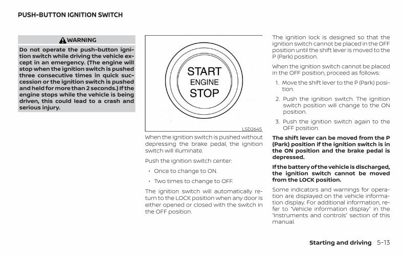
WARNINGDo not operate the push-button igni-tion switch while driving the vehicle ex-cept in an emergency. (The engine willstop when the ignition switch is pushedthree consecutive times in quick suc-cession or the ignition switch is pushedand held for more than 2 seconds.) If theengine stops while the vehicle is beingdriven, this could lead to a crash andserious injury.
When the ignition switch is pushed withoutdepressing the brake pedal, the ignitionswitch will illuminate.
Push the ignition switch center:
∙ Once to change to ON.
∙ Two times to change to OFF.
The ignition switch will automatically re-turn to the LOCK position when any door iseither opened or closed with the switch inthe OFF position.
The ignition lock is designed so that theignition switch cannot be placed in the OFFposition until the shift lever is moved to theP (Park) position.
When the ignition switch cannot be placedin the OFF position, proceed as follows:
1. Move the shift lever to the P (Park) posi-tion.
2. Push the ignition switch. The ignitionswitch position will change to the ONposition.
3. Push the ignition switch again to theOFF position.
The shift lever can be moved from the P(Park) position if the ignition switch is inthe ON position and the brake pedal isdepressed.
If the battery of the vehicle is discharged,the ignition switch cannot be movedfrom the LOCK position.
Some indicators and warnings for opera-tion are displayed on the vehicle informa-tion display. For additional information, re-fer to “Vehicle information display” in the“Instruments and controls” section of thismanual.
LSD2645
PUSH-BUTTON IGNITION SWITCH
Starting and driving 5-13
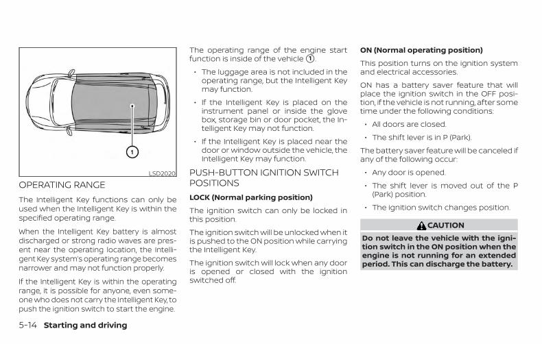
OPERATING RANGEThe Intelligent Key functions can only beused when the Intelligent Key is within thespecified operating range.
When the Intelligent Key battery is almostdischarged or strong radio waves are pres-ent near the operating location, the Intelli-gent Key system’s operating range becomesnarrower and may not function properly.
If the Intelligent Key is within the operatingrange, it is possible for anyone, even some-one who does not carry the Intelligent Key, topush the ignition switch to start the engine.
The operating range of the engine startfunction is inside of the vehicle �1 .
∙ The luggage area is not included in theoperating range, but the Intelligent Keymay function.
∙ If the Intelligent Key is placed on theinstrument panel or inside the glovebox, storage bin or door pocket, the In-telligent Key may not function.
∙ If the Intelligent Key is placed near thedoor or window outside the vehicle, theIntelligent Key may function.
PUSH-BUTTON IGNITION SWITCHPOSITIONSLOCK (Normal parking position)
The ignition switch can only be locked inthis position.
The ignition switch will be unlocked when itis pushed to the ON position while carryingthe Intelligent Key.
The ignition switch will lock when any dooris opened or closed with the ignitionswitched off.
ON (Normal operating position)
This position turns on the ignition systemand electrical accessories.
ON has a battery saver feature that willplace the ignition switch in the OFF posi-tion, if the vehicle is not running, after sometime under the following conditions:
∙ All doors are closed.
∙ The shift lever is in P (Park).
The battery saver feature will be canceled ifany of the following occur:
∙ Any door is opened.
∙ The shift lever is moved out of the P(Park) position.
∙ The ignition switch changes position.
CAUTIONDo not leave the vehicle with the igni-tion switch in the ON position when theengine is not running for an extendedperiod. This can discharge the battery.
LSD2020
5-14 Starting and driving
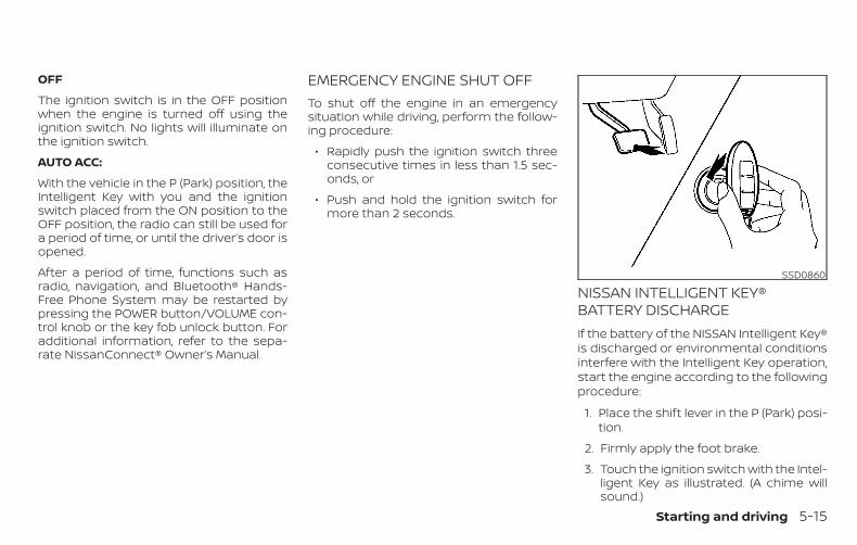
OFF
The ignition switch is in the OFF positionwhen the engine is turned off using theignition switch. No lights will illuminate onthe ignition switch.
AUTO ACC:
With the vehicle in the P (Park) position, theIntelligent Key with you and the ignitionswitch placed from the ON position to theOFF position, the radio can still be used fora period of time, or until the driver’s door isopened.
After a period of time, functions such asradio, navigation, and Bluetooth® Hands-Free Phone System may be restarted bypressing the POWER button/VOLUME con-trol knob or the key fob unlock button. Foradditional information, refer to the sepa-rate NissanConnect® Owner’s Manual.
EMERGENCY ENGINE SHUT OFFTo shut off the engine in an emergencysituation while driving, perform the follow-ing procedure:
∙ Rapidly push the ignition switch threeconsecutive times in less than 1.5 sec-onds, or
∙ Push and hold the ignition switch formore than 2 seconds.
NISSAN INTELLIGENT KEY®BATTERY DISCHARGEIf the battery of the NISSAN Intelligent Key®is discharged or environmental conditionsinterfere with the Intelligent Key operation,start the engine according to the followingprocedure:
1. Place the shift lever in the P (Park) posi-tion.
2. Firmly apply the foot brake.
3. Touch the ignition switch with the Intel-ligent Key as illustrated. (A chime willsound.)
SSD0860
Starting and driving 5-15
After step 3 is performed, when theignition switch is pushed without de-pressing the brake pedal, the ignitionswitch position will change to the ONposition.
4. Push the ignition switch while depress-ing the brake pedal within 10 secondsafter the chime sounds. The engine willstart.
NOTE:
∙ When the ignition switch is pushed tothe ON position or the engine isstarted by the above procedure, theIntelligent Key battery discharge in-dicator appears in the vehicle infor-mation display even when the Intelli-gent Key is inside the vehicle. This isnot a malfunction. To turn off the In-telligent Key battery discharge indi-cator, touch the ignition switch withthe Intelligent Key again.
∙ If the Intelligent Key battery dis-charge indicator appears, replace thebattery as soon as possible. For addi-tional information, refer to “Batteryreplacement” in the “Do-it-yourself”section of this manual.
NISSAN VEHICLE IMMOBILIZERSYSTEMThe NISSAN Vehicle Immobilizer Systemwill not allow the engine to start withoutthe use of the registered key.
If the engine fails to start using a registeredkey (for example, when interference iscaused by another registered key, an auto-mated toll road device or automatic pay-ment device on the key ring), restart theengine using the following procedure:
1. Leave the ignition switch in the ON po-sition for approximately 5 seconds.
2. Place the ignition switch in the OFF orLOCK position, and wait approximately10 seconds.
3. Repeat steps 1 and 2.
4. Restart the engine while holding thedevice (which may have caused the in-terference) separate from the regis-tered key.
If the no start condition re-occurs, NISSANrecommends placing the registered key ona separate key ring to avoid interferencefrom other devices.
∙ Make sure the area around the vehicle isclear.
∙ Check fluid levels such as engine oil,coolant, brake fluid, and windshield-washer fluid as frequently as possible,or at least whenever you refuel.
∙ Check that all windows and lights areclean.
∙ Visually inspect tires for their appear-ance and condition. Also check tires forproper inflation.
∙ Lock all doors.
∙ Position seat and adjust headrests/head restraints.
∙ Adjust inside and outside mirrors.
∙ Fasten seat belts and ask all passen-gers to do likewise.
∙ Check the operation of warning lightswhen the ignition switch is pushed tothe ON position. For additional informa-tion, refer to “Warning lights, indicatorlights and audible reminders” in the “In-struments and controls” section of thismanual.
BEFORE STARTING THE ENGINE
5-16 Starting and driving
1. Apply the parking brake.
2. Move the shift lever to P (Park) or N(Neutral). P (Park) is recommended.
The starter is designed not to oper-ate if the shift lever is in any of thedriving positions.
3. Push the ignition switch to the ON po-sition. Depress the brake pedal andpush the ignition switch to start theengine.
To start the engine immediately, pushand release the ignition switch whiledepressing the brake pedal with theignition switch in any position.
∙ If the engine is very hard to start inextremely cold weather or when re-starting, depress the acceleratorpedal a little (approximately 1/3 to thefloor) and while holding, crank the en-gine. Release the accelerator pedalwhen the engine starts.
∙ If the engine is very hard to start be-cause it is flooded, depress the accel-erator pedal all the way to the floorand hold it. Push the ignition switchto the ON position to start crankingthe engine. After 5 or 6 seconds, stopcranking by pushing the ignition
switch to the LOCK position. Aftercranking the engine, release the ac-celerator pedal. Crank the enginewith your foot off the acceleratorpedal by depressing the brake pedaland pushing the ignition switch tostart the engine. If the engine starts,but fails to run, repeat the above pro-cedure.
CAUTIONDo not operate the starter for morethan 15 seconds at a time. If the enginedoes not start, push the ignition switchto the OFF position and wait 10 secondsbefore cranking again, otherwise thestarter could be damaged.
4. Warm-up:
Allow the engine to idle for at least30 seconds after starting. Do not racethe engine while warming it up. Drive ata moderate speed for a short distancefirst, especially in cold weather. In coldweather, keep the engine running for aminimum of 2 to 3 minutes beforeshutting it off. Starting and stoppingthe engine over a short period of timemay make the vehicle more difficult tostart.
5. To stop the engine, move the shift leverto the P (Park) position and push theignition switch to the OFF position.
NOTE:
Care should be taken to avoid situationsthat can lead to potential battery dis-charge and potential no-start conditionssuch as:
1. Installation or extended use of elec-tronic accessories that consume bat-tery power when the engine is notrunning (phone chargers, GPS, DVDplayers, etc.).
2. The vehicle is not driven regularlyand/or only driven short distances.
In these cases, the battery may need tobe charged to maintain battery health.
STARTING THE ENGINE
Starting and driving 5-17
REMOTE ENGINE START (if soequipped)Vehicles started with the Remote EngineStart require the ignition switch to beplaced in the ON position before the shiftlever can be moved from the P (Park) posi-tion. To place the ignition switch in the ONposition, follow these steps:
1. Make sure that the Intelligent Key is onyou.
2. Apply the brake.
3. Push the ignition switch once to the ONposition.
For additional information, refer to “NISSANIntelligent Key®” in the “Pre-driving checksand adjustments” section of this manual.
CONTINUOUSLY VARIABLETRANSMISSION (CVT)
WARNING∙ Do not depress the accelerator pedal
while shifting from P (Park) or N (Neu-tral) to R (Reverse), D (Drive), L (Low) ormanual shift mode (if so equipped).Always depress the brake pedal untilshifting is completed. Failure to do socould cause you to lose control andhave an accident.
∙ Cold engine idle speed is high, so usecaution when shifting into a forwardor reverse gear before the engine haswarmed up.
∙ Do not downshift abruptly on slipperyroads. This may cause a loss ofcontrol.
∙ Never shift to either the P (Park) or R(Reverse) position while the vehicle ismoving forward and P (Park) or D(Drive) position while the vehicle is re-versing. This could cause an accidentor damage the transmission.
CAUTION∙ Except in an emergency, do not shift
to the N (Neutral) position while driv-ing. Coasting with the transmission inthe N (Neutral) position may cause se-rious damage to the transmission.
∙ To avoid possible damage to your ve-hicle, when stopping the vehicle on anuphill grade, do not hold the vehicle bydepressing the accelerator pedal. Thefoot brake should be used for thispurpose.
The CVT in your vehicle is electronicallycontrolled to produce maximum powerand smooth operation.
Follow these procedures for maximum ve-hicle performance and driving enjoyment.
NOTE:
Engine power may be automatically re-duced to protect the CVT if the enginespeed increases quickly when driving onslippery roads or while being tested onsome dynamometers.
DRIVING THE VEHICLE
5-18 Starting and driving
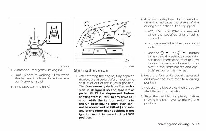
1. Automatic Emergency Braking (AEB)
2. Lane Departure Warning (LDW) whenshaded and Intelligent Lane Interven-tion (I-LI) when solid
3. Blind Spot Warning (BSW)
Starting the vehicle1. After starting the engine, fully depress
the foot brake pedal before moving theshift lever out of the P (Park) position.The Continuously Variable Transmis-sion is designed so the foot brakepedal MUST be depressed beforeshifting from P (Park) to any drive po-sition while the ignition switch is inthe ON position.The shift lever can-not be moved out of P (Park) and intoany of the other gear positions if theignition switch is placed in the LOCKposition.
2. A screen is displayed for a period oftime that indicates the status of thedriving aid functions (if so equipped).
– AEB, LDW, and BSW are enabledwhen the specified driving aid isshaded.
– I-LI is enabled when the driving aid issolid.
– Use the �1 or �2 buttonto navigate the settings screen. Foradditional information, refer to “Howto use the vehicle information dis-play” in the “Instruments and con-trols” section of this manual.
3. Keep the foot brake pedal depressedand move the shift lever to a drivingposition.
4. Release the foot brake, then graduallystart the vehicle in motion.
5. Stop the vehicle completely beforemoving the shift lever to the P (Park)position.
LSD3073 LSD3074
Starting and driving 5-19
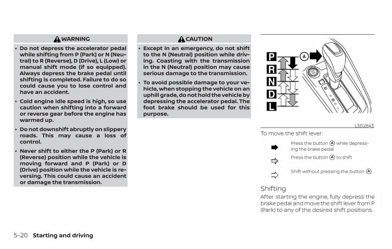
WARNING∙ Do not depress the accelerator pedal
while shifting from P (Park) or N (Neu-tral) to R (Reverse), D (Drive), L (Low) ormanual shift mode (if so equipped).Always depress the brake pedal untilshifting is completed. Failure to do socould cause you to lose control andhave an accident.
∙ Cold engine idle speed is high, so usecaution when shifting into a forwardor reverse gear before the engine haswarmed up.
∙ Do not downshift abruptly on slipperyroads. This may cause a loss ofcontrol.
∙ Never shift to either the P (Park) or R(Reverse) position while the vehicle ismoving forward and P (Park) or D(Drive) position while the vehicle is re-versing. This could cause an accidentor damage the transmission.
CAUTION∙ Except in an emergency, do not shift
to the N (Neutral) position while driv-ing. Coasting with the transmissionin the N (Neutral) position may causeserious damage to the transmission.
∙ To avoid possible damage to your ve-hicle, when stopping the vehicle on anuphill grade, do not hold the vehicle bydepressing the accelerator pedal. Thefoot brake should be used for thispurpose.
To move the shift lever:
Press the button �A while depress-ing the brake pedal
Press the button �A to shift
Shift without pressing the button �A
ShiftingAfter starting the engine, fully depress thebrake pedal and move the shift lever from P(Park) to any of the desired shift positions.
LSD2643
5-20 Starting and driving

WARNINGApply the parking brake if the shift leveris in any position while the engine is notrunning. Failure to do so could causethe vehicle to move unexpectedly or rollaway and result in serious personal in-jury or property damage.
P (Park)
CAUTIONTo prevent transmission damage, usethe P (Park) or R (Reverse) positiononly when the vehicle is completelystopped.
Use the P (Park) shift lever position whenthe vehicle is parked or when starting theengine. Make sure the vehicle is completelystopped. The brake pedal should be de-pressed to move the shift lever from N(Neutral) or any drive position to P (Park).Apply the parking brake. When parking on ahill, apply the parking brake first, then movethe shift lever into the P (Park) position.
R (Reverse)
CAUTIONTo prevent transmission damage, usethe P (Park) or R (Reverse) position onlywhen the vehicle is completelystopped.
Use the R (Reverse) position to back up.Make sure the vehicle is completelystopped before selecting the R (Reverse)position. The brake pedal must be de-pressed to move the shift lever from P(Park), N (Neutral) or any drive position toR (Reverse).
N (Neutral)
Neither forward nor reverse gear is en-gaged. The engine can be started in thisposition. You may shift to N (Neutral) andrestart a stalled engine while the vehicle ismoving.
D (Drive)
Use this position for all normal forwarddriving.
L (Low)
Use this position for engine braking onsteep downhill gradients/climbing steepslopes and whenever approaching sharpbends. Do not use the L (Low) position inany other circumstances.
Starting and driving 5-21
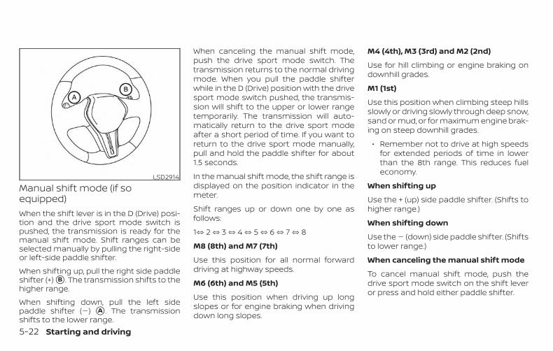
Manual shift mode (if soequipped)When the shift lever is in the D (Drive) posi-tion and the drive sport mode switch ispushed, the transmission is ready for themanual shift mode. Shift ranges can beselected manually by pulling the right-sideor left-side paddle shifter.
When shifting up, pull the right side paddleshifter (+) �B . The transmission shifts to thehigher range.
When shifting down, pull the left sidepaddle shifter (�) �A . The transmissionshifts to the lower range.
When canceling the manual shift mode,push the drive sport mode switch. Thetransmission returns to the normal drivingmode. When you pull the paddle shifterwhile in the D (Drive) position with the drivesport mode switch pushed, the transmis-sion will shift to the upper or lower rangetemporarily. The transmission will auto-matically return to the drive sport modeafter a short period of time. If you want toreturn to the drive sport mode manually,pull and hold the paddle shifter for about1.5 seconds.
In the manual shift mode, the shift range isdisplayed on the position indicator in themeter.
Shift ranges up or down one by one asfollows:
1⇔ 2 ⇔ 3 ⇔ 4 ⇔ 5 ⇔ 6 ⇔ 7 ⇔ 8
M8 (8th) and M7 (7th)
Use this position for all normal forwarddriving at highway speeds.
M6 (6th) and M5 (5th)
Use this position when driving up longslopes or for engine braking when drivingdown long slopes.
M4 (4th), M3 (3rd) and M2 (2nd)
Use for hill climbing or engine braking ondownhill grades.
M1 (1st)
Use this position when climbing steep hillsslowly or driving slowly through deep snow,sand or mud, or for maximum engine brak-ing on steep downhill grades.
∙ Remember not to drive at high speedsfor extended periods of time in lowerthan the 8th range. This reduces fueleconomy.
When shifting up
Use the + (up) side paddle shifter. (Shifts tohigher range.)
When shifting down
Use the � (down) side paddle shifter. (Shiftsto lower range.)
When canceling the manual shift mode
To cancel manual shift mode, push thedrive sport mode switch on the shift leveror press and hold either paddle shifter.
LSD2914
5-22 Starting and driving
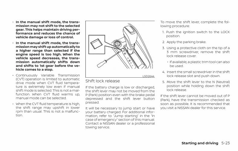
∙ In the manual shift mode, the trans-mission may not shift to the selectedgear. This helps maintain driving per-formance and reduces the chance ofvehicle damage or loss of control.
∙ In the manual shift mode, the trans-mission may shift up automatically toa higher range than selected if theengine speed is too high. When thevehicle speed decreases, the trans-mission automatically shifts downand shifts to 1st gear before the ve-hicle comes to a stop.
∙ Continuously Variable Transmission(CVT) operation is limited to automaticdrive mode when CVT fluid tempera-ture is extremely low even if manualshift mode is selected. This is not a mal-function. When CVT fluid warms up,manual mode can be selected.
∙ When the CVT fluid temperature is high,the shift range may upshift in lowerrpm than usual. This is not a malfunc-tion.
Shift lock releaseIf the battery charge is low or discharged,the shift lever may not be moved from theP (Park) position even with the brake pedaldepressed and the shift lever buttonpressed.
It will be necessary to jump start or haveyour battery charged. For additional infor-mation, refer to “Jump starting” in the “Incase of emergency” section of this manual.Contact a NISSAN dealer or a professionaltowing service.
To move the shift lever, complete the fol-lowing procedure:
1. Push the ignition switch to the LOCKposition.
2. Apply the parking brake.
3. Using a protective cloth on the tip of a3 mm screwdriver, remove the shiftlock release cover.
∙ If available, a plastic trim tool can alsobe used.
4. Insert the small screwdriver in the shiftlock release slot and push down.
5. Move the shift lever to the N (Neutral)position while holding down the shiftlock release.
If the shift lever cannot be moved out of P(Park), have the transmission checked assoon as possible. It is recommended thatyou visit a NISSAN dealer for this service.
LSD2644
Starting and driving 5-23
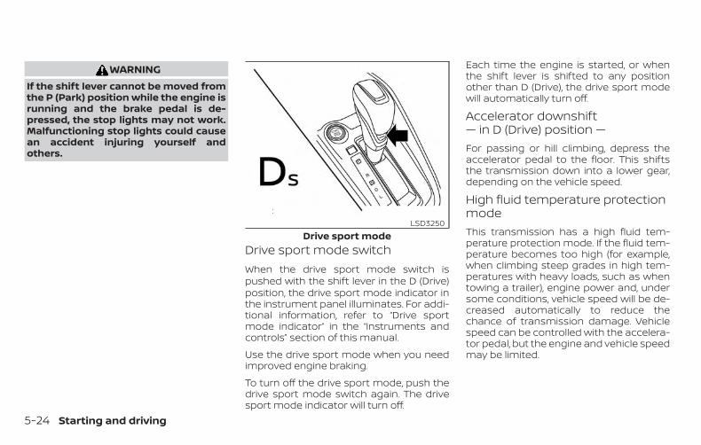
WARNINGIf the shift lever cannot be moved fromthe P (Park) position while the engine isrunning and the brake pedal is de-pressed, the stop lights may not work.Malfunctioning stop lights could causean accident injuring yourself andothers.
Drive sport mode switchWhen the drive sport mode switch ispushed with the shift lever in the D (Drive)position, the drive sport mode indicator inthe instrument panel illuminates. For addi-tional information, refer to “Drive sportmode indicator” in the “Instruments andcontrols” section of this manual.
Use the drive sport mode when you needimproved engine braking.
To turn off the drive sport mode, push thedrive sport mode switch again. The drivesport mode indicator will turn off.
Each time the engine is started, or whenthe shift lever is shifted to any positionother than D (Drive), the drive sport modewill automatically turn off.
Accelerator downshift— in D (Drive) position —For passing or hill climbing, depress theaccelerator pedal to the floor. This shiftsthe transmission down into a lower gear,depending on the vehicle speed.
High fluid temperature protectionmodeThis transmission has a high fluid tem-perature protection mode. If the fluid tem-perature becomes too high (for example,when climbing steep grades in high tem-peratures with heavy loads, such as whentowing a trailer), engine power and, undersome conditions, vehicle speed will be de-creased automatically to reduce thechance of transmission damage. Vehiclespeed can be controlled with the accelera-tor pedal, but the engine and vehicle speedmay be limited.
Drive sport modeLSD3250
5-24 Starting and driving
Fail-safeIf the vehicle is driven under extremeconditions, such as excessive wheelspinning and subsequent hard braking,the fail-safe system may be activated.The Malfunction Indicator Light (MIL)may come on to indicate the fail-safemode is activated. For additional infor-mation, refer to “Malfunction IndicatorLight (MIL)” in the “Instruments and con-trols” section of this manual. This will oc-cur even if all electrical circuits are func-tioning properly. In this case, place theignition switch in the OFF position andwait for 10 seconds. Then push theswitch back to the ON position. The ve-hicle should return to its normal operat-ing condition. If it does not return to itsnormal operating condition, have thetransmission checked. It is recom-mended that you visit a NISSAN dealerfor this service.
WARNINGWhen the high fluid temperature pro-tection mode or fail-safe operation oc-curs, vehicle speed may be gradually re-duced. The reduced speed may be lowerthan other traffic, which could increasethe chance of a collision. Be especiallycareful when driving. If necessary, pullto the side of the road at a safe placeand allow the transmission to return tonormal operation, or have it repaired ifnecessary.
WARNING∙ Be sure the parking brake is fully re-
leased before driving. Failure to do socan cause brake failure and lead to anaccident.
∙ Do not release the parking brake fromoutside the vehicle.
∙ Do not use the shift lever in place ofthe parking brake. When parking, besure the parking brake is fullyengaged.
∙ To help avoid risk of injury or deaththrough unintended operation of thevehicle and/or its systems, do notleave children, people who require theassistance of others or pets unat-tended in your vehicle. Additionally,the temperature inside a closed ve-hicle on a warm day can quickly be-come high enough to cause a signifi-cant risk of injury or death to peopleand pets.
PARKING BRAKE
Starting and driving 5-25
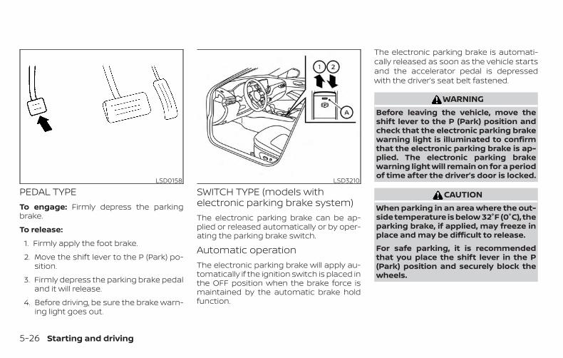
PEDAL TYPETo engage: Firmly depress the parkingbrake.
To release:
1. Firmly apply the foot brake.
2. Move the shift lever to the P (Park) po-sition.
3. Firmly depress the parking brake pedaland it will release.
4. Before driving, be sure the brake warn-ing light goes out.
SWITCH TYPE (models withelectronic parking brake system)The electronic parking brake can be ap-plied or released automatically or by oper-ating the parking brake switch.
Automatic operationThe electronic parking brake will apply au-tomatically if the ignition switch is placed inthe OFF position when the brake force ismaintained by the automatic brake holdfunction.
The electronic parking brake is automati-cally released as soon as the vehicle startsand the accelerator pedal is depressedwith the driver’s seat belt fastened.
WARNINGBefore leaving the vehicle, move theshift lever to the P (Park) position andcheck that the electronic parking brakewarning light is illuminated to confirmthat the electronic parking brake is ap-plied. The electronic parking brakewarning light will remain on for a periodof time after the driver’s door is locked.
CAUTIONWhen parking in an area where the out-side temperature is below 32°F (0°C), theparking brake, if applied, may freeze inplace and may be difficult to release.
For safe parking, it is recommendedthat you place the shift lever in the P(Park) position and securely block thewheels.
LSD0158 LSD3210
5-26 Starting and driving

NOTE:
∙ To keep the electronic parking brakereleased after the engine is turnedoff, place the ignition switch in theOFF position, depress the brake pedaland push down the parking brakeswitch before opening the driver’sdoor.
∙ If a malfunction occurs in the elec-tronic parking brake system (for ex-ample, due to battery discharge), it isrecommended that you visit a NISSANdealer.
∙ If the shift lever is moved to the P(Park) position when the brake forceis maintained by the automatic brakehold function, the electronic parkingbrake will apply automatically.
∙ If the driver’s seat belt is unfastenedwhen the brake force is maintainedby the automatic brake hold function,the electronic parking brake will ap-ply automatically.
∙ If the ignition switch is placed in theOFF position when the brake force ismaintained by the automatic brakehold function, the electronic parkingbrake will apply automatically.
Manual operationThe electronic parking brake will not be au-tomatically applied if the engine is stoppedwithout using the ignition switch (for ex-ample, by engine stalling). In such a case,you have to apply the parking brake manu-ally.
To apply: Pull the switch up �1 . The indica-tor light �A will illuminate.
To release: With the ignition switch in theON position, depress the brake pedal andpush the switch down �2 . The indicatorlight �A will turn off.
Before driving, check that the electronicparking brake indicator light ( or PARK)goes out. For additional information, referto “Warning lights, indicator lights and au-dible reminders” in the “Instruments andcontrols” section of this manual.
NOTE:
∙ A buzzer will sound if the vehicle isdriven without releasing the parkingbrake. For additional information, re-fer to “Warning lights, indicator lightsand audible reminders” in the “Instru-ments and controls” section of thismanual.
∙ While the electronic parking brake isapplied or released, an operatingsound is heard from the lower side ofthe rear seat. This is normal and doesnot indicate a malfunction.
∙ When the electronic parking brake isfrequently applied and released in ashort period of time, the parkingbrake may not operate in order toprevent the parking brake systemfrom overheating. If this occurs, oper-ate the electronic parking brakeswitch again after waiting approxi-mately 1 minute.
∙ If the electronic parking brake mustbe applied while driving in an emer-gency, pull up and hold the parkingbrake switch. When you release theparking brake switch, the parkingbrake will be released.
Starting and driving 5-27
∙ While pulling up the electronic park-ing brake switch during driving, theparking brake is applied and a chimesounds. The electronic parking brakeindicator light in the meter and in theparking brake switch illuminates.This does not indicate a malfunction.The electronic parking brake indica-tor light in the meter and in the park-ing brake switch turns off when theparking brake is released.
∙ When pulling the electronic parkingbrake switch up with the ignitionswitch in the OFF or AUTO ACC posi-tion, the parking brake switch indica-tor light will continue to illuminate fora short period of time.
The automatic brake hold function main-tains the braking force without the driverhaving to depress the brake pedal whenthe vehicle is stopped at a traffic light orintersection. As soon as the driver de-presses the accelerator pedal again, theautomatic brake hold function is deacti-vated and the braking force is released. Theoperating status of the automatic brakehold can be displayed on the vehicle infor-mation display.
WARNING∙ The automatic brake hold function is
not designed to hold the vehicle on asteep hill or slippery road. Never usethe automatic brake hold when thevehicle is stopped on a steep hill orslippery road. Failure to do so maycause the vehicle to move.
∙ When the automatic brake hold func-tion is activated but fails to maintainthe vehicle at a standstill, depress thebrake pedal to stop the vehicle. If thevehicle unexpectedly moves due tooutside conditions, the chime maysound and automatic brake holdwarning may illuminate in the vehicleinformation display.
∙ Be sure to deactivate the automaticbrake hold function when using a carwash or towing your vehicle.
∙ Make sure to place the shift lever inthe P (Park) position and apply theparking brake when parking your ve-hicle or loading luggage. Failure to doso could cause the vehicle to move orroll away unexpectedly and result inserious personal injury or propertydamage.
∙ If any of the following conditions oc-cur, the automatic brake hold functionmay not function. Have the systemchecked promptly. It is recommendedthat you visit a NISSAN dealer for thisservice. Failure to operate the vehiclein accordance with these conditionscould cause the vehicle to move or rollaway unexpectedly and result in seri-ous personal injury or propertydamage.
– A warning message appears in thevehicle information display.
– The indicator light on the auto-matic brake hold switch does notilluminate when the switch ispushed.
AUTOMATIC BRAKE HOLD (if soequipped)
5-28 Starting and driving
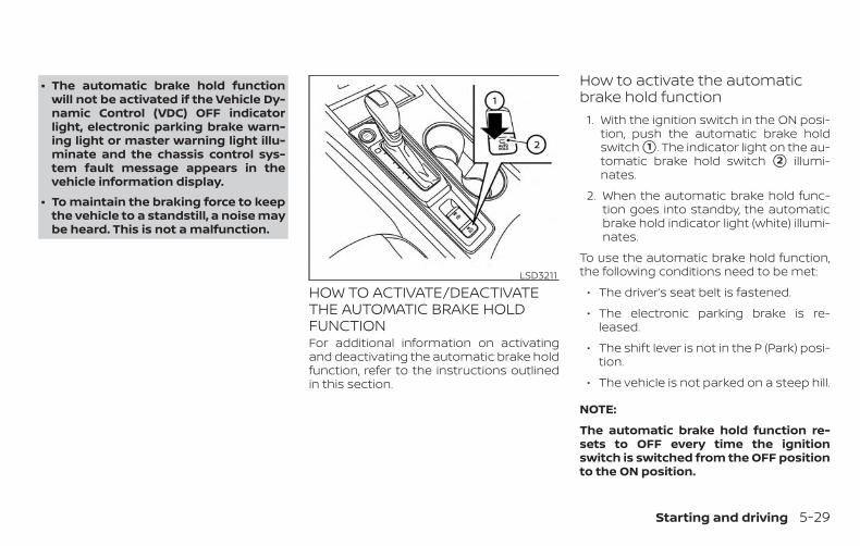
∙ The automatic brake hold functionwill not be activated if the Vehicle Dy-namic Control (VDC) OFF indicatorlight, electronic parking brake warn-ing light or master warning light illu-minate and the chassis control sys-tem fault message appears in thevehicle information display.
∙ To maintain the braking force to keepthe vehicle to a standstill, a noise maybe heard. This is not a malfunction.
HOW TO ACTIVATE/DEACTIVATETHE AUTOMATIC BRAKE HOLDFUNCTIONFor additional information on activatingand deactivating the automatic brake holdfunction, refer to the instructions outlinedin this section.
How to activate the automaticbrake hold function
1. With the ignition switch in the ON posi-tion, push the automatic brake holdswitch �1 . The indicator light on the au-tomatic brake hold switch �2 illumi-nates.
2. When the automatic brake hold func-tion goes into standby, the automaticbrake hold indicator light (white) illumi-nates.
To use the automatic brake hold function,the following conditions need to be met:
∙ The driver’s seat belt is fastened.
∙ The electronic parking brake is re-leased.
∙ The shift lever is not in the P (Park) posi-tion.
∙ The vehicle is not parked on a steep hill.
NOTE:
The automatic brake hold function re-sets to OFF every time the ignitionswitch is switched from the OFF positionto the ON position.
LSD3211
Starting and driving 5-29
How to deactivate the automaticbrake hold functionWhile the automatic brake hold function isactivated, push the automatic brake holdswitch to turn off the automatic brake holdindicator light and deactivate the auto-matic brake hold function. To deactivatethe automatic brake hold function whilethe brake force has been maintained bythe automatic brake hold function, depressthe brake pedal and push the automaticbrake hold switch.
WARNINGMake sure to firmly depress and holdthe brake pedal when turning off theautomatic brake hold function whilethe brake force is applied. When the au-tomatic brake hold function is deacti-vated, the brake force will be released.This could cause the vehicle to move orroll away unexpectedly. Failure to pre-vent the vehicle from rolling may resultin serious personal injury or propertydamage.
HOW TO USE THE AUTOMATICBRAKE HOLD FUNCTIONFor additional information on using the au-tomatic brake hold function, refer to theinstructions outlined in this section.
To maintain braking forceautomaticallyWith the automatic brake hold function ac-tivated and the automatic brake hold indi-cator light (white) illuminated on the meter,depress the braking pedal to stop the ve-hicle. The brake force is automaticallymaintained without your foot depressedon the brake pedal. While the brake hold ismaintained, the automatic brake hold indi-cator light (green) illuminates on the meter.
To start the vehicle from astandstillWith the shift lever not in the P (Park) or N(Neutral) position, depress the acceleratorpedal while the brake force is maintained.The brake force will automatically be re-leased to restart the vehicle.
The automatic brake hold indicator light(white) on the meter illuminates and theautomatic brake hold returns to standby.
ParkingWhen the shift lever is in the P (Park) posi-tion with the brake force maintained by theautomatic brake hold function, the parkingbrake will automatically be applied and thebrake force of the automatic brake hold willbe released. The automatic brake hold in-dicator light turns off. When the parkingbrake is applied with the brake force main-tained by the automatic brake hold func-tion, the brake force of the automatic brakehold will be released. The automatic brakehold indicator light turns off.
NOTE:
∙ Under the following conditions, theparking brake will automatically beapplied and the brake force of the au-tomatic brake hold will be released:
– The braking force is applied by theautomatic brake hold function for3 minutes or longer.
– The driver’s seat belt is unfas-tened.
– The ignition switch is placed in theOFF position.
– If a malfunction occurs in the au-tomatic brake hold function.
5-30 Starting and driving
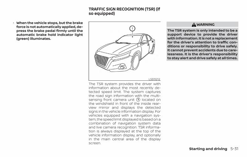
∙ When the vehicle stops, but the brakeforce is not automatically applied, de-press the brake pedal firmly until theautomatic brake hold indicator light(green) illuminates.
The TSR system provides the driver withinformation about the most recently de-tected speed limit. The system capturesthe road sign information with the multi-sensing front camera unit �1 located onthe windshield in front of the inside rear-view mirror and displays the detectedsigns in the vehicle information display. Forvehicles equipped with a navigation sys-tem, the speed limit displayed is based on acombination of navigation system dataand live camera recognition. TSR informa-tion is always displayed at the top of thevehicle information display, and optionallyin the main central area of the displayscreen.
WARNINGThe TSR system is only intended to be asupport device to provide the driverwith information. It is not a replacementfor the driver’s attention to traffic con-ditions or responsibility to drive safely.It cannot prevent accidents due to care-lessness. It is the driver’s responsibilityto stay alert and drive safely at all times.
LSD3212
TRAFFIC SIGN RECOGNITION (TSR) (ifso equipped)
Starting and driving 5-31
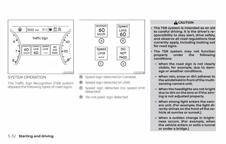
SYSTEM OPERATIONThe Traffic Sign Recognition (TSR) systemdisplays the following types of road signs:
�A Speed sign detected (in Canada)
�B Speed sign detected (in USA)
�C Speed sign detected (no speed limitdetected)
�D “Do not pass” sign detected
CAUTION∙ The TSR system is intended as an aid
to careful driving. It is the driver’s re-sponsibility to stay alert, drive safely,and observe all road regulations thatcurrently apply, including looking outfor road signs.
∙ The TSR system may not functionproperly under the followingconditions:
– When the road sign is not clearlyvisible, for example, due to dam-age or weather conditions.
– When rain, snow or dirt adheres tothe windshield in front of the multi-sensing camera unit.
– When the headlights are not brightdue to dirt on the lens or if the aim-ing is not adjusted properly.
– When strong light enters the cam-era unit. (For example, the light di-rectly shines on the front of the ve-hicle at sunrise or sunset.)
– When a sudden change in bright-ness occurs. (For example, whenthe vehicle enters or exits a tunnelor under a bridge.)
LSD3330 LSD3378
5-32 Starting and driving
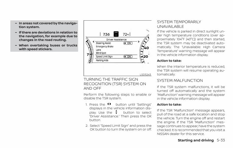
– In areas not covered by the naviga-tion system.
– If there are deviations in relation tothe navigation, for example due tochanges in the road routing.
– When overtaking buses or truckswith speed stickers.
TURNING THE TRAFFIC SIGNRECOGNITION (TSR) SYSTEM ONAND OFFPerform the following steps to enable ordisable the TSR system.
1. Press the button until “Settings”displays in the vehicle information dis-play. Use the button to select“Driver Assistance.” Then press the OKbutton.
2. Select “Speed Limit Sign” and press theOK button to turn the system on or off.
SYSTEM TEMPORARILYUNAVAILABLEIf the vehicle is parked in direct sunlight un-der high temperature conditions (over ap-proximately 104°F [40°C]) and then started,the TSR system may be deactivated auto-matically. The “Unavailable: High CameraTemperature” warning message will appearin the vehicle information display.
Action to take:
When the interior temperature is reduced,the TSR system will resume operating au-tomatically.
SYSTEM MALFUNCTIONIf the TSR system malfunctions, it will beturned off automatically and the system“Malfunction” warning message will appearin the vehicle information display.
Action to take:
If the TSR “Malfunction” message appears,pull of the road at a safe location and stopthe vehicle. Turn the engine off and restartthe engine. If the TSR “Malfunction” mes-sage continues to appear, have the systemchecked. It is recommended that you visit aNISSAN dealer for this service.
LSD3243
Starting and driving 5-33
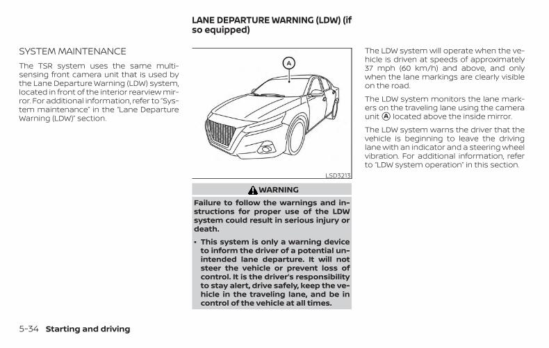
SYSTEM MAINTENANCEThe TSR system uses the same multi-sensing front camera unit that is used bythe Lane Departure Warning (LDW) system,located in front of the interior rearview mir-ror. For additional information, refer to ”Sys-tem maintenance” in the “Lane DepartureWarning (LDW)” section.
WARNINGFailure to follow the warnings and in-structions for proper use of the LDWsystem could result in serious injury ordeath.
∙ This system is only a warning deviceto inform the driver of a potential un-intended lane departure. It will notsteer the vehicle or prevent loss ofcontrol. It is the driver’s responsibilityto stay alert, drive safely, keep the ve-hicle in the traveling lane, and be incontrol of the vehicle at all times.
The LDW system will operate when the ve-hicle is driven at speeds of approximately37 mph (60 km/h) and above, and onlywhen the lane markings are clearly visibleon the road.
The LDW system monitors the lane mark-ers on the traveling lane using the cameraunit �A located above the inside mirror.
The LDW system warns the driver that thevehicle is beginning to leave the drivinglane with an indicator and a steering wheelvibration. For additional information, referto “LDW system operation” in this section.
LSD3213
LANE DEPARTURE WARNING (LDW) (ifso equipped)
5-34 Starting and driving
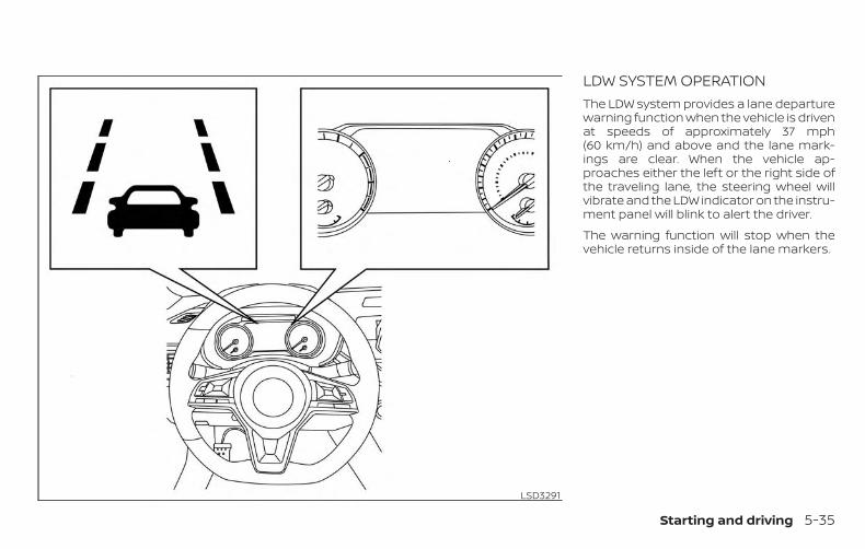
LDW SYSTEM OPERATIONThe LDW system provides a lane departurewarning function when the vehicle is drivenat speeds of approximately 37 mph(60 km/h) and above and the lane mark-ings are clear. When the vehicle ap-proaches either the left or the right side ofthe traveling lane, the steering wheel willvibrate and the LDW indicator on the instru-ment panel will blink to alert the driver.
The warning function will stop when thevehicle returns inside of the lane markers.
LSD3291
Starting and driving 5-35
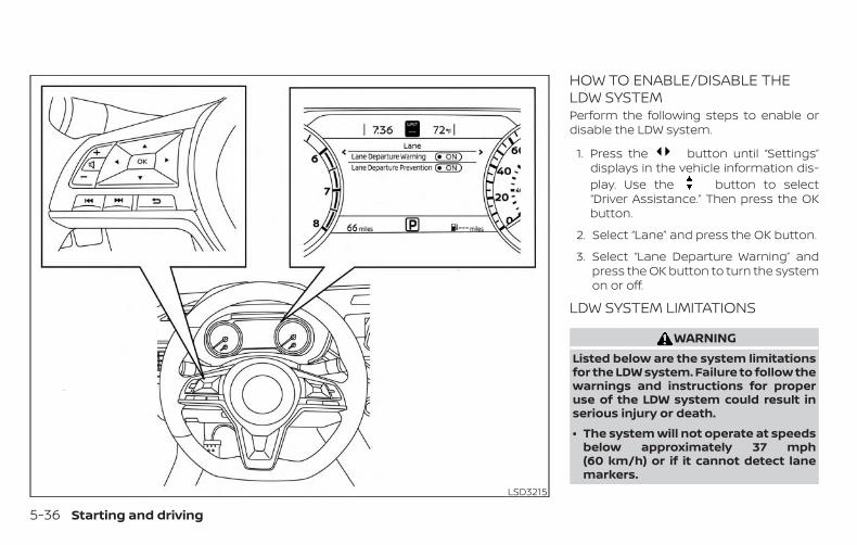
HOW TO ENABLE/DISABLE THELDW SYSTEMPerform the following steps to enable ordisable the LDW system.
1. Press the button until “Settings”displays in the vehicle information dis-play. Use the button to select“Driver Assistance.” Then press the OKbutton.
2. Select “Lane” and press the OK button.
3. Select “Lane Departure Warning” andpress the OK button to turn the systemon or off.
LDW SYSTEM LIMITATIONS
WARNINGListed below are the system limitationsfor the LDW system. Failure to follow thewarnings and instructions for properuse of the LDW system could result inserious injury or death.
∙ The system will not operate at speedsbelow approximately 37 mph(60 km/h) or if it cannot detect lanemarkers.
LSD3215
5-36 Starting and driving
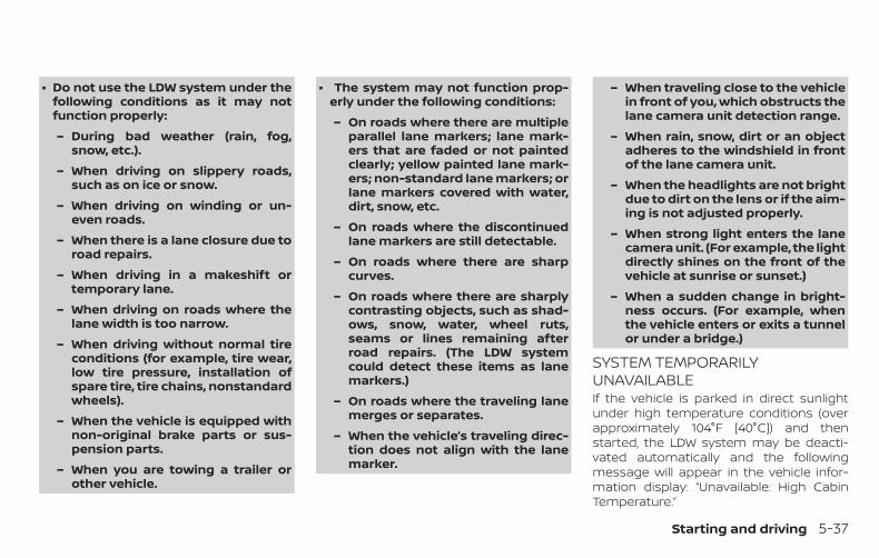
∙ Do not use the LDW system under thefollowing conditions as it may notfunction properly:
– During bad weather (rain, fog,snow, etc.).
– When driving on slippery roads,such as on ice or snow.
– When driving on winding or un-even roads.
– When there is a lane closure due toroad repairs.
– When driving in a makeshift ortemporary lane.
– When driving on roads where thelane width is too narrow.
– When driving without normal tireconditions (for example, tire wear,low tire pressure, installation ofspare tire, tire chains, nonstandardwheels).
– When the vehicle is equipped withnon-original brake parts or sus-pension parts.
– When you are towing a trailer orother vehicle.
∙ The system may not function prop-erly under the following conditions:
– On roads where there are multipleparallel lane markers; lane mark-ers that are faded or not paintedclearly; yellow painted lane mark-ers; non-standard lane markers; orlane markers covered with water,dirt, snow, etc.
– On roads where the discontinuedlane markers are still detectable.
– On roads where there are sharpcurves.
– On roads where there are sharplycontrasting objects, such as shad-ows, snow, water, wheel ruts,seams or lines remaining afterroad repairs. (The LDW systemcould detect these items as lanemarkers.)
– On roads where the traveling lanemerges or separates.
– When the vehicle’s traveling direc-tion does not align with the lanemarker.
– When traveling close to the vehiclein front of you, which obstructs thelane camera unit detection range.
– When rain, snow, dirt or an objectadheres to the windshield in frontof the lane camera unit.
– When the headlights are not brightdue to dirt on the lens or if the aim-ing is not adjusted properly.
– When strong light enters the lanecamera unit. (For example, the lightdirectly shines on the front of thevehicle at sunrise or sunset.)
– When a sudden change in bright-ness occurs. (For example, whenthe vehicle enters or exits a tunnelor under a bridge.)
SYSTEM TEMPORARILYUNAVAILABLEIf the vehicle is parked in direct sunlightunder high temperature conditions (overapproximately 104°F [40°C]) and thenstarted, the LDW system may be deacti-vated automatically and the followingmessage will appear in the vehicle infor-mation display: “Unavailable: High CabinTemperature.”
Starting and driving 5-37
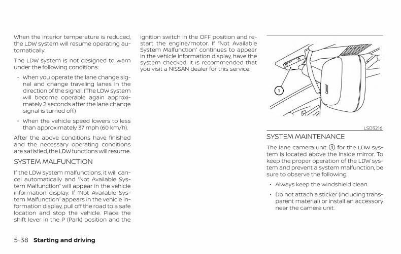
When the interior temperature is reduced,the LDW system will resume operating au-tomatically.
The LDW system is not designed to warnunder the following conditions:
∙ When you operate the lane change sig-nal and change traveling lanes in thedirection of the signal. (The LDW systemwill become operable again approxi-mately 2 seconds after the lane changesignal is turned off.)
∙ When the vehicle speed lowers to lessthan approximately 37 mph (60 km/h).
After the above conditions have finishedand the necessary operating conditionsare satisfied, the LDW functions will resume.
SYSTEM MALFUNCTIONIf the LDW system malfunctions, it will can-cel automatically and “Not Available Sys-tem Malfunction” will appear in the vehicleinformation display. If “Not Available Sys-tem Malfunction” appears in the vehicle in-formation display, pull off the road to a safelocation and stop the vehicle. Place theshift lever in the P (Park) position and the
ignition switch in the OFF position and re-start the engine/motor. If “Not AvailableSystem Malfunction” continues to appearin the vehicle information display, have thesystem checked. It is recommended thatyou visit a NISSAN dealer for this service.
SYSTEM MAINTENANCEThe lane camera unit �1 for the LDW sys-tem is located above the inside mirror. Tokeep the proper operation of the LDW sys-tem and prevent a system malfunction, besure to observe the following:
∙ Always keep the windshield clean.
∙ Do not attach a sticker (including trans-parent material) or install an accessorynear the camera unit.
LSD3216
5-38 Starting and driving
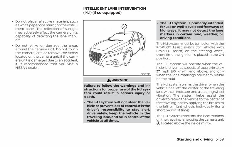
∙ Do not place reflective materials, suchas white paper or a mirror, on the instru-ment panel. The reflection of sunlightmay adversely affect the camera unit’scapability of detecting the lane mark-ers.
∙ Do not strike or damage the areasaround the camera unit. Do not touchthe camera lens or remove the screwlocated on the camera unit. If the cam-era unit is damaged due to an accident,it is recommended that you visit aNISSAN dealer.
WARNINGFailure to follow the warnings and in-structions for proper use of the I-LI sys-tem could result in serious injury ordeath.
∙ The I-LI system will not steer the ve-hicle or prevent loss of control. It is thedriver’s responsibility to stay alert,drive safely, keep the vehicle in thetraveling lane, and be in control of thevehicle at all times.
∙ The I-LI system is primarily intendedfor use on well-developed freeways orhighways. It may not detect the lanemarkers in certain road, weather, ordriving conditions.
The I-LI system must be turned on with theProPILOT Assist switch (for vehicles withProPILOT Assist) on the steering wheel,every time the ignition is placed in the ONposition.
The I-LI system will operate when the ve-hicle is driven at speeds of approximately37 mph (60 km/h) and above, and onlywhen the lane markings are clearly visibleon the road.
The I-LI system warns the driver when thevehicle has left the center of the travelinglane with an indicator and a steering wheelvibration. The system helps assist thedriver to return the vehicle to the center ofthe traveling lane by applying the brakes tothe left or right wheels individually (for ashort period of time).
The I-LI system monitors the lane markerson the traveling lane using the camera unit�A located above the inside mirror.
LSD3213
INTELLIGENT LANE INTERVENTION(I-LI) (if so equipped)
Starting and driving 5-39
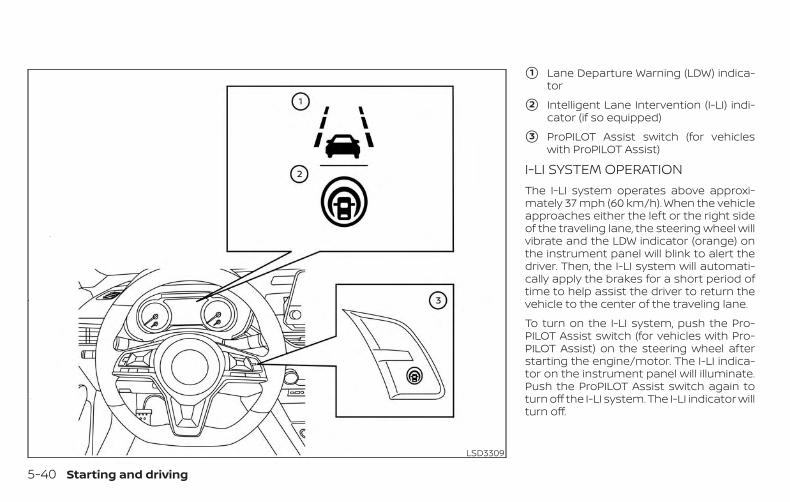
�1 Lane Departure Warning (LDW) indica-tor
�2 Intelligent Lane Intervention (I-LI) indi-cator (if so equipped)
�3 ProPILOT Assist switch (for vehicleswith ProPILOT Assist)
I-LI SYSTEM OPERATIONThe I-LI system operates above approxi-mately 37 mph (60 km/h). When the vehicleapproaches either the left or the right sideof the traveling lane, the steering wheel willvibrate and the LDW indicator (orange) onthe instrument panel will blink to alert thedriver. Then, the I-LI system will automati-cally apply the brakes for a short period oftime to help assist the driver to return thevehicle to the center of the traveling lane.
To turn on the I-LI system, push the Pro-PILOT Assist switch (for vehicles with Pro-PILOT Assist) on the steering wheel afterstarting the engine/motor. The I-LI indica-tor on the instrument panel will illuminate.Push the ProPILOT Assist switch again toturn off the I-LI system. The I-LI indicator willturn off.
LSD3309
5-40 Starting and driving
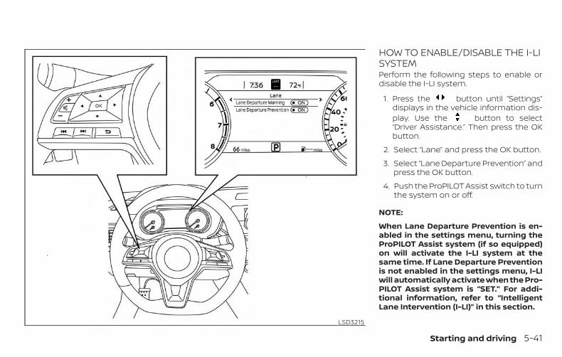
HOW TO ENABLE/DISABLE THE I-LISYSTEMPerform the following steps to enable ordisable the I-LI system.
1. Press the button until “Settings”displays in the vehicle information dis-play. Use the button to select“Driver Assistance.” Then press the OKbutton.
2. Select “Lane” and press the OK button.
3. Select “Lane Departure Prevention” andpress the OK button.
4. Push the ProPILOT Assist switch to turnthe system on or off.
NOTE:
When Lane Departure Prevention is en-abled in the settings menu, turning theProPILOT Assist system (if so equipped)on will activate the I-LI system at thesame time. If Lane Departure Preventionis not enabled in the settings menu, I-LIwill automatically activate when the Pro-PILOT Assist system is “SET.” For addi-tional information, refer to “IntelligentLane Intervention (I-LI)” in this section.
LSD3215
Starting and driving 5-41
I-LI SYSTEM LIMITATIONS
WARNINGListed below are the system limitationsfor the I-LI system. Failure to follow thewarnings and instructions for properuse of the I-LI system could result inserious injury or death.
∙ The I-LI system may activate if youchange lanes without first activatingyour turn signal or, for example, if aconstruction zone directs traffic tocross an existing lane marker. If thisoccurs you may need to apply correc-tive steering to complete your lanechange.
∙ Because the I-LI may not activate un-der the road, weather, and lanemarker conditions described in thissection, it may not activate every timeyour vehicle begins to leave its laneand you will need to apply correctivesteering.
∙ When the I-LI system is operating,avoid excessive or sudden steeringmaneuvers. Otherwise, you could losecontrol of the vehicle.
∙ The I-LI system will not operate atspeeds below approximately 37 mph(60 km/h) or if it cannot detect lanemarkers.
∙ Do not use the I-LI system under thefollowing conditions as it may notfunction properly:
– During bad weather (rain, fog,snow, etc.).
– When driving on slippery roads,such as on ice or snow.
– When driving on winding or un-even roads.
– When there is a lane closure due toroad repairs.
– When driving in a makeshift ortemporary lane.
– When driving on roads where thelane width is too narrow.
– When driving without normal tireconditions (for example, tire wear,low tire pressure, installation ofspare tire, tire chains, non-standard wheels).
– When the vehicle is equipped withnonoriginal brake parts or suspen-sion parts.
– When you are towing a trailer orother vehicle.
– On roads where there are multipleparallel lane markers; lane mark-ers that are faded or not paintedclearly; yellow painted lane mark-ers; non-standard lane markers; orlane markers covered with water,dirt, snow, etc.
– On roads where discontinued lanemarkers are still detectable.
– On roads where there are sharpcurves.
– On roads where there are sharplycontrasting objects, such as shad-ows, snow, water, wheel ruts,seams or lines remaining afterroad repairs. (The I-LI system coulddetect these items as lanemarkers.)
– On roads where the traveling lanemerges or separates.
5-42 Starting and driving
– When the vehicle’s traveling direc-tion does not align with the lanemarker.
– When traveling close to the vehiclein front of you, which obstructs thelane camera unit detection range.
– When rain, snow or dirt adheres tothe windshield in front of the lanecamera unit.
– When the headlights are not brightdue to dirt on the lens or if the aim-ing is not adjusted properly.
– When strong light enters the lanecamera unit. (For example, the lightdirectly shines on the front of thevehicle at sunrise or sunset.)
– When a sudden change in bright-ness occurs. (For example, whenthe vehicle enters or exits a tunnelor under a bridge.)
While the I-LI system is operating, you mayhear a sound of brake operation. This isnormal and indicates that the I-LI system isoperating properly.
SYSTEM TEMPORARILYUNAVAILABLECondition A:
The warning and assist functions of the I-LIsystem are not designed to work under thefollowing conditions:
∙ When you operate the lane change sig-nal and change the traveling lanes inthe direction of the signal. (The I-LI sys-tem will be deactivated for approxi-mately 2 seconds after the lane changesignal is turned off.)
∙ When the vehicle speed lowers to lessthan approximately 37 mph (60 km/h).
After the above conditions have finishedand the necessary operating conditionsare satisfied, the warning and assist func-tions will resume.
Condition B:
The assist function of the I-LI system is notdesigned to work under the following con-ditions (warning is still functional):
∙ When the brake pedal is depressed.
∙ When the steering wheel is turned as faras necessary for the vehicle to changelanes.
∙ When the vehicle is accelerated duringI-LI system operation.
∙ When the Intelligent Cruise Control (ICC)approach warning occurs.
∙ When the hazard warning flashers areoperated.
∙ When driving on a curve at high speed.
After the above conditions have finishedand the necessary operating conditionsare satisfied, the I-LI system application ofthe brakes will resume.
Condition C:
If the following messages appear in thevehicle information display, the I-LI systemwill be turned off automatically.
∙ “Not Available Poor Road Conditions”:When the VDC system (except TractionControl System [TCS] function) or ABSoperates.
∙ “Currently not available”:When the VDC system is turned off.
Action to take:
When the above conditions no longer exist,turn off the I-LI system. Push the ProPILOTAssist switch (for vehicles with ProPILOT
Starting and driving 5-43
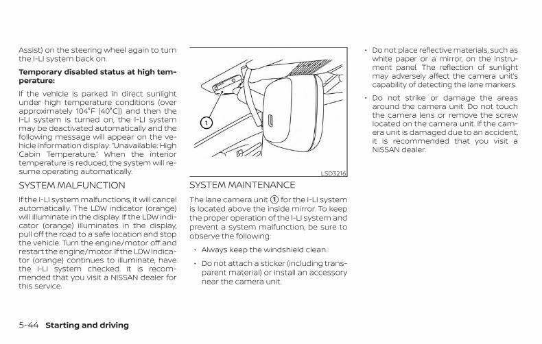
Assist) on the steering wheel again to turnthe I-LI system back on.
Temporary disabled status at high tem-perature:
If the vehicle is parked in direct sunlightunder high temperature conditions (overapproximately 104°F [40°C]) and then theI-LI system is turned on, the I-LI systemmay be deactivated automatically and thefollowing message will appear on the ve-hicle information display: “Unavailable: HighCabin Temperature.” When the interiortemperature is reduced, the system will re-sume operating automatically.
SYSTEM MALFUNCTIONIf the I-LI system malfunctions, it will cancelautomatically. The LDW indicator (orange)will illuminate in the display. If the LDW indi-cator (orange) illuminates in the display,pull off the road to a safe location and stopthe vehicle. Turn the engine/motor off andrestart the engine/motor. If the LDW indica-tor (orange) continues to illuminate, havethe I-LI system checked. It is recom-mended that you visit a NISSAN dealer forthis service.
SYSTEM MAINTENANCEThe lane camera unit �1 for the I-LI systemis located above the inside mirror. To keepthe proper operation of the I-LI system andprevent a system malfunction, be sure toobserve the following:
∙ Always keep the windshield clean.
∙ Do not attach a sticker (including trans-parent material) or install an accessorynear the camera unit.
∙ Do not place reflective materials, such aswhite paper or a mirror, on the instru-ment panel. The reflection of sunlightmay adversely affect the camera unit’scapability of detecting the lane markers.
∙ Do not strike or damage the areasaround the camera unit. Do not touchthe camera lens or remove the screwlocated on the camera unit. If the cam-era unit is damaged due to an accident,it is recommended that you visit aNISSAN dealer.
LSD3216
5-44 Starting and driving
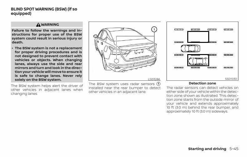
WARNINGFailure to follow the warnings and in-structions for proper use of the BSWsystem could result in serious injury ordeath.
∙ The BSW system is not a replacementfor proper driving procedures and isnot designed to prevent contact withvehicles or objects. When changinglanes, always use the side and rearmirrors and turn and look in the direc-tion your vehicle will move to ensure itis safe to change lanes. Never relysolely on the BSW system.
The BSW system helps alert the driver ofother vehicles in adjacent lanes whenchanging lanes.
The BSW system uses radar sensors �1installed near the rear bumper to detectother vehicles in an adjacent lane.
The radar sensors can detect vehicles oneither side of your vehicle within the detec-tion zone shown as illustrated. This detec-tion zone starts from the outside mirror ofyour vehicle and extends approximately10 ft (3.0 m) behind the rear bumper, andapproximately 10 ft (3.0 m) sideways.
LSD3286Detection zone
SSD1030
BLIND SPOT WARNING (BSW) (if soequipped)
Starting and driving 5-45
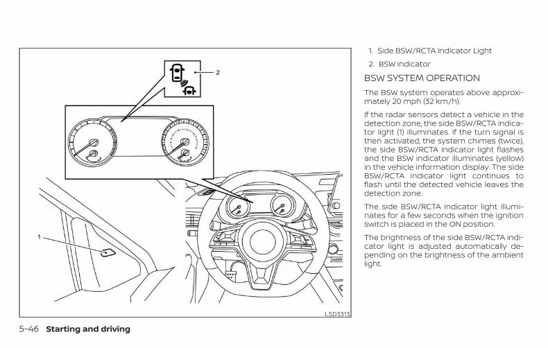
1. Side BSW/RCTA Indicator Light
2. BSW indicator
BSW SYSTEM OPERATIONThe BSW system operates above approxi-mately 20 mph (32 km/h).
If the radar sensors detect a vehicle in thedetection zone, the side BSW/RCTA indica-tor light (1) illuminates. If the turn signal isthen activated, the system chimes (twice),the side BSW/RCTA indicator light flashesand the BSW indicator illuminates (yellow)in the vehicle information display. The sideBSW/RCTA indicator light continues toflash until the detected vehicle leaves thedetection zone.
The side BSW/RCTA indicator light illumi-nates for a few seconds when the ignitionswitch is placed in the ON position.
The brightness of the side BSW/RCTA indi-cator light is adjusted automatically de-pending on the brightness of the ambientlight.
LSD3313
5-46 Starting and driving
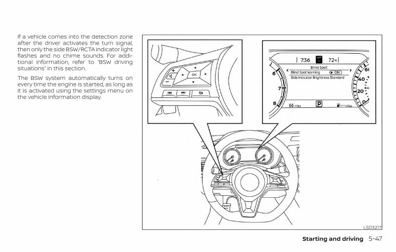
If a vehicle comes into the detection zoneafter the driver activates the turn signal,then only the side BSW/RCTA indicator lightflashes and no chime sounds. For addi-tional information, refer to “BSW drivingsituations” in this section.
The BSW system automatically turns onevery time the engine is started, as long asit is activated using the settings menu onthe vehicle information display.
LSD3217
Starting and driving 5-47
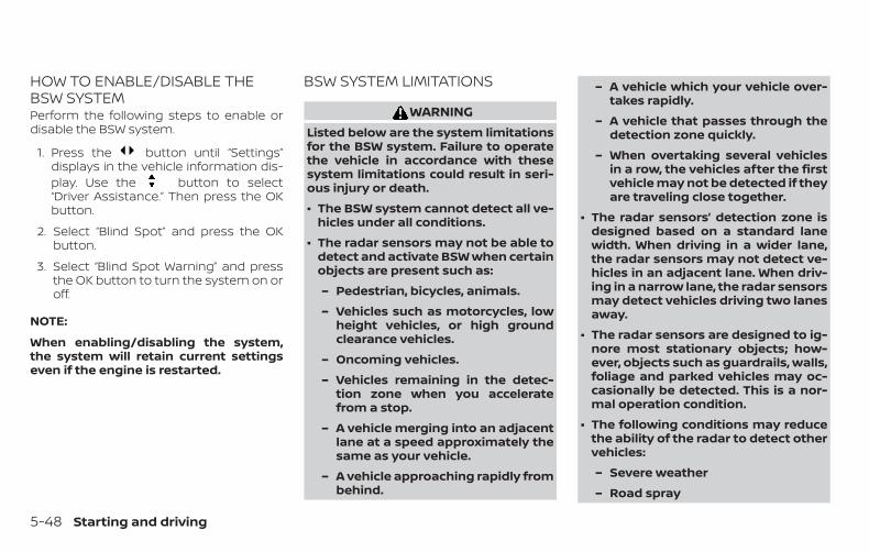
HOW TO ENABLE/DISABLE THEBSW SYSTEMPerform the following steps to enable ordisable the BSW system.
1. Press the button until “Settings”displays in the vehicle information dis-play. Use the button to select“Driver Assistance.” Then press the OKbutton.
2. Select “Blind Spot” and press the OKbutton.
3. Select “Blind Spot Warning” and pressthe OK button to turn the system on oroff.
NOTE:
When enabling/disabling the system,the system will retain current settingseven if the engine is restarted.
BSW SYSTEM LIMITATIONS
WARNINGListed below are the system limitationsfor the BSW system. Failure to operatethe vehicle in accordance with thesesystem limitations could result in seri-ous injury or death.
∙ The BSW system cannot detect all ve-hicles under all conditions.
∙ The radar sensors may not be able todetect and activate BSW when certainobjects are present such as:
– Pedestrian, bicycles, animals.
– Vehicles such as motorcycles, lowheight vehicles, or high groundclearance vehicles.
– Oncoming vehicles.
– Vehicles remaining in the detec-tion zone when you acceleratefrom a stop.
– A vehicle merging into an adjacentlane at a speed approximately thesame as your vehicle.
– A vehicle approaching rapidly frombehind.
– A vehicle which your vehicle over-takes rapidly.
– A vehicle that passes through thedetection zone quickly.
– When overtaking several vehiclesin a row, the vehicles after the firstvehicle may not be detected if theyare traveling close together.
∙ The radar sensors’ detection zone isdesigned based on a standard lanewidth. When driving in a wider lane,the radar sensors may not detect ve-hicles in an adjacent lane. When driv-ing in a narrow lane, the radar sensorsmay detect vehicles driving two lanesaway.
∙ The radar sensors are designed to ig-nore most stationary objects; how-ever, objects such as guardrails, walls,foliage and parked vehicles may oc-casionally be detected. This is a nor-mal operation condition.
∙ The following conditions may reducethe ability of the radar to detect othervehicles:
– Severe weather
– Road spray
5-48 Starting and driving
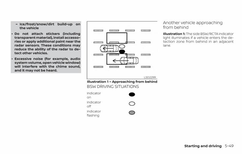
– Ice/frost/snow/dirt build-up onthe vehicle
∙ Do not attach stickers (includingtransparent material), install accesso-ries or apply additional paint near theradar sensors. These conditions mayreduce the ability of the radar to de-tect other vehicles.
∙ Excessive noise (for example, audiosystem volume, open vehicle window)will interfere with the chime sound,and it may not be heard.
BSW DRIVING SITUATIONSIndicatoronIndicatoroffIndicatorflashing
Another vehicle approachingfrom behindIllustration 1: The side BSW/RCTA indicatorlight illuminates if a vehicle enters the de-tection zone from behind in an adjacentlane.
Illustration 1 – Approaching from behindLSD2299
Starting and driving 5-49
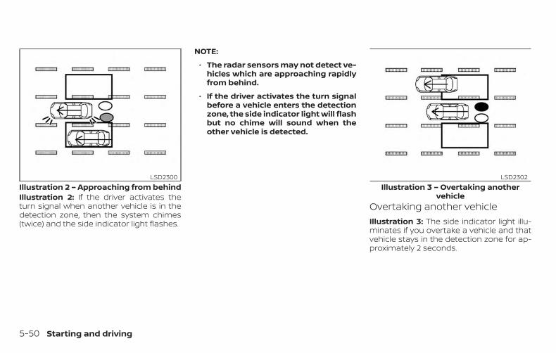
Illustration 2: If the driver activates theturn signal when another vehicle is in thedetection zone, then the system chimes(twice) and the side indicator light flashes.
NOTE:
∙ The radar sensors may not detect ve-hicles which are approaching rapidlyfrom behind.
∙ If the driver activates the turn signalbefore a vehicle enters the detectionzone, the side indicator light will flashbut no chime will sound when theother vehicle is detected.
Overtaking another vehicleIllustration 3: The side indicator light illu-minates if you overtake a vehicle and thatvehicle stays in the detection zone for ap-proximately 2 seconds.
Illustration 2 – Approaching from behindLSD2300
Illustration 3 – Overtaking anothervehicle
LSD2302
5-50 Starting and driving
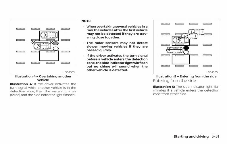
Illustration 4: If the driver activates theturn signal while another vehicle is in thedetection zone, then the system chimes(twice) and the side indicator light flashes.
NOTE:
∙ When overtaking several vehicles in arow, the vehicles after the first vehiclemay not be detected if they are trav-eling close together.
∙ The radar sensors may not detectslower moving vehicles if they arepassed quickly.
∙ If the driver activates the turn signalbefore a vehicle enters the detectionzone, the side indicator light will flashbut no chime will sound when theother vehicle is detected.
Entering from the sideIllustration 5: The side indicator light illu-minates if a vehicle enters the detectionzone from either side.
Illustration 4 – Overtaking anothervehicle
LSD2303Illustration 5 – Entering from the side
LSD2305
Starting and driving 5-51
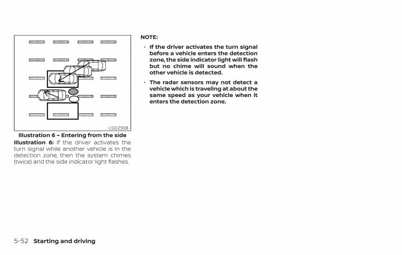
Illustration 6: If the driver activates theturn signal while another vehicle is in thedetection zone, then the system chimes(twice) and the side indicator light flashes.
NOTE:
∙ If the driver activates the turn signalbefore a vehicle enters the detectionzone, the side indicator light will flashbut no chime will sound when theother vehicle is detected.
∙ The radar sensors may not detect avehicle which is traveling at about thesame speed as your vehicle when itenters the detection zone.
Illustration 6 – Entering from the sideLSD2308
5-52 Starting and driving
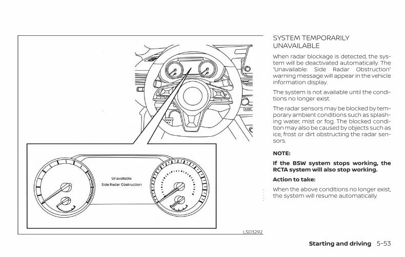
SYSTEM TEMPORARILYUNAVAILABLEWhen radar blockage is detected, the sys-tem will be deactivated automatically. The“Unavailable: Side Radar Obstruction”warning message will appear in the vehicleinformation display.
The system is not available until the condi-tions no longer exist.
The radar sensors may be blocked by tem-porary ambient conditions such as splash-ing water, mist or fog. The blocked condi-tion may also be caused by objects such asice, frost or dirt obstructing the radar sen-sors.
NOTE:
If the BSW system stops working, theRCTA system will also stop working.
Action to take:
When the above conditions no longer exist,the system will resume automatically.
LSD3292
Starting and driving 5-53
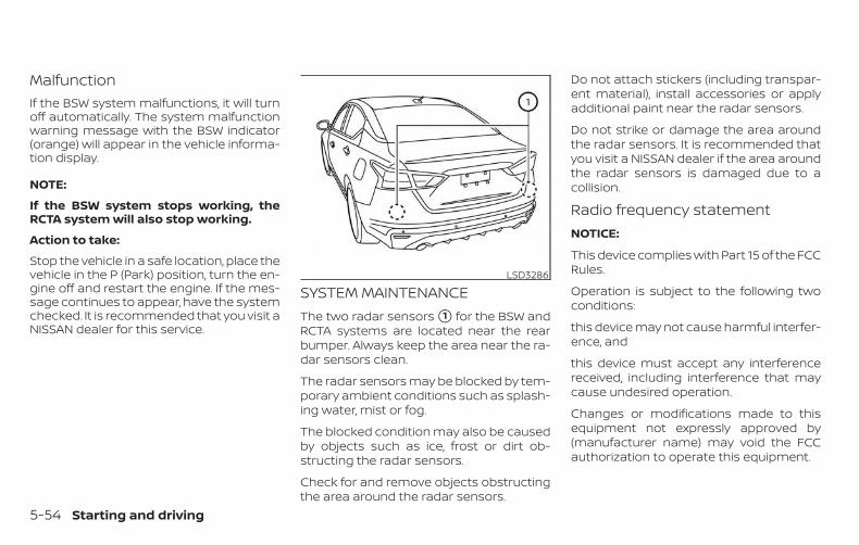
MalfunctionIf the BSW system malfunctions, it will turnoff automatically. The system malfunctionwarning message with the BSW indicator(orange) will appear in the vehicle informa-tion display.
NOTE:
If the BSW system stops working, theRCTA system will also stop working.
Action to take:
Stop the vehicle in a safe location, place thevehicle in the P (Park) position, turn the en-gine off and restart the engine. If the mes-sage continues to appear, have the systemchecked. It is recommended that you visit aNISSAN dealer for this service.
SYSTEM MAINTENANCEThe two radar sensors �1 for the BSW andRCTA systems are located near the rearbumper. Always keep the area near the ra-dar sensors clean.
The radar sensors may be blocked by tem-porary ambient conditions such as splash-ing water, mist or fog.
The blocked condition may also be causedby objects such as ice, frost or dirt ob-structing the radar sensors.
Check for and remove objects obstructingthe area around the radar sensors.
Do not attach stickers (including transpar-ent material), install accessories or applyadditional paint near the radar sensors.
Do not strike or damage the area aroundthe radar sensors. It is recommended thatyou visit a NISSAN dealer if the area aroundthe radar sensors is damaged due to acollision.
Radio frequency statementNOTICE:
This device complies with Part 15 of the FCCRules.
Operation is subject to the following twoconditions:
this device may not cause harmful interfer-ence, and
this device must accept any interferencereceived, including interference that maycause undesired operation.
Changes or modifications made to thisequipment not expressly approved by(manufacturer name) may void the FCCauthorization to operate this equipment.
LSD3286
5-54 Starting and driving
NOTE:
This equipment has been tested andfound to comply with the limits for aClass B digital device, pursuant to Part 15of the FCC Rules. These limits are de-signed to provide reasonable protectionagainst harmful interference in a resi-dential installation. This equipment gen-erates, uses and can radiate radio fre-quency energy and, if not installed andused in accordance with the instruc-tions, may cause harmful interference toradio communications. However, there isno guarantee that interference will notoccur in a particular installation. If thisequipment does cause harmful interfer-ence to radio or television reception,which can be determined by turning theequipment off and on, the user is en-couraged to try to correct the interfer-ence by one or more of the followingmeasures:
Reorient or relocate the receiving an-tenna.
Increase the separation between theequipment and receiver.
Connect the equipment into an outlet ona circuit different from that to which thereceiver is connected.
Consult the dealer or an experiencedradio/TV technician for help.
WARNINGFailure to follow the warnings and in-structions for proper use of the RCTAcould result in serious injury or death.
∙ The RCTA system is not a replacementfor proper driving procedures and isnot designed to prevent contact withvehicles or objects. When backing outof a parking space, always use theside and rear mirrors and turn andlook in the direction your vehicle willmove. Never rely solely on the RCTAsystem.
The RCTA system will assist you whenbacking out from a parking space. Whenthe vehicle is in reverse, the system is de-signed to detect other vehicles approach-ing from the right or left of the vehicle. If thesystem detects cross traffic, it will alert you.
REAR CROSS TRAFFIC ALERT (RCTA)(if so equipped)
Starting and driving 5-55
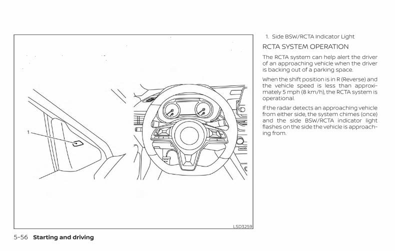
1. Side BSW/RCTA Indicator Light
RCTA SYSTEM OPERATIONThe RCTA system can help alert the driverof an approaching vehicle when the driveris backing out of a parking space.
When the shift position is in R (Reverse) andthe vehicle speed is less than approxi-mately 5 mph (8 km/h), the RCTA system isoperational.
If the radar detects an approaching vehiclefrom either side, the system chimes (once)and the side BSW/RCTA indicator lightflashes on the side the vehicle is approach-ing from.
LSD3259
5-56 Starting and driving
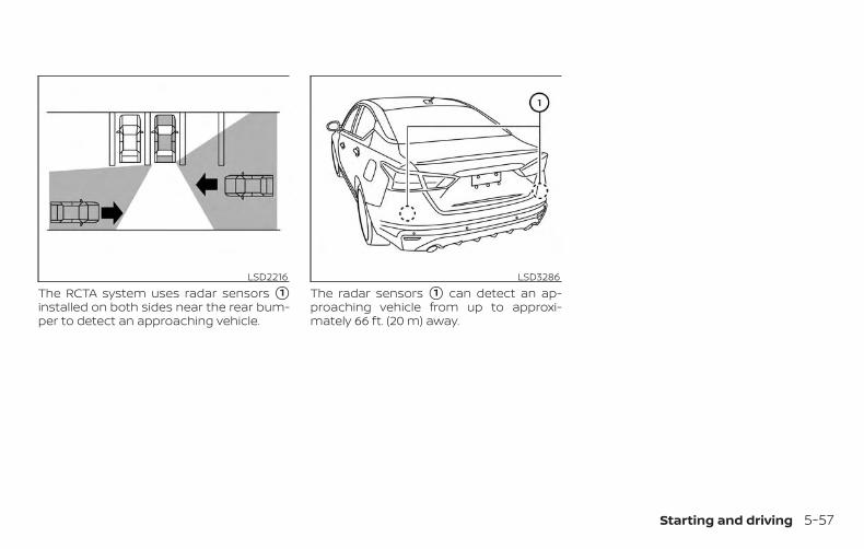
The RCTA system uses radar sensors �1installed on both sides near the rear bum-per to detect an approaching vehicle.
The radar sensors �1 can detect an ap-proaching vehicle from up to approxi-mately 66 ft. (20 m) away.
LSD2216 LSD3286
Starting and driving 5-57
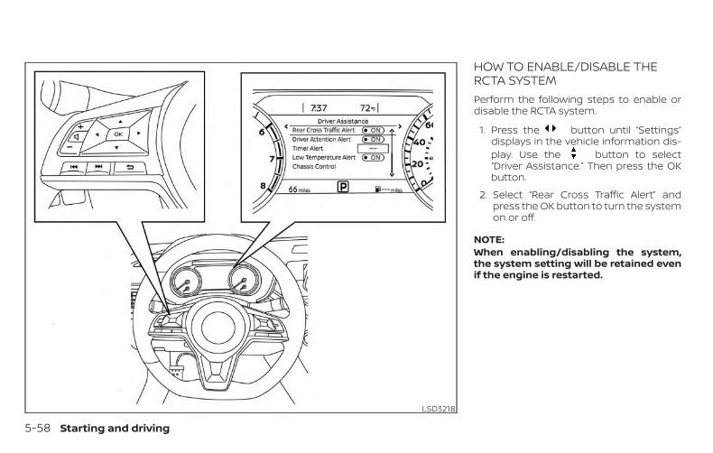
HOW TO ENABLE/DISABLE THERCTA SYSTEMPerform the following steps to enable ordisable the RCTA system.
1. Press the button until “Settings”displays in the vehicle information dis-play. Use the button to select“Driver Assistance.” Then press the OKbutton.
2. Select “Rear Cross Traffic Alert” andpress the OK button to turn the systemon or off.
NOTE:When enabling/disabling the system,the system setting will be retained evenif the engine is restarted.
LSD3218
5-58 Starting and driving
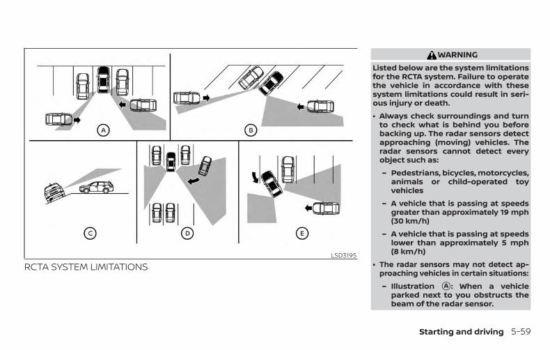
RCTA SYSTEM LIMITATIONS
WARNINGListed below are the system limitationsfor the RCTA system. Failure to operatethe vehicle in accordance with thesesystem limitations could result in seri-ous injury or death.
∙ Always check surroundings and turnto check what is behind you beforebacking up. The radar sensors detectapproaching (moving) vehicles. Theradar sensors cannot detect everyobject such as:
– Pedestrians, bicycles, motorcycles,animals or child-operated toyvehicles
– A vehicle that is passing at speedsgreater than approximately 19 mph(30 km/h)
– A vehicle that is passing at speedslower than approximately 5 mph(8 km/h)
∙ The radar sensors may not detect ap-proaching vehicles in certain situations:
– Illustration �A : When a vehicleparked next to you obstructs thebeam of the radar sensor.
LSD3195
Starting and driving 5-59
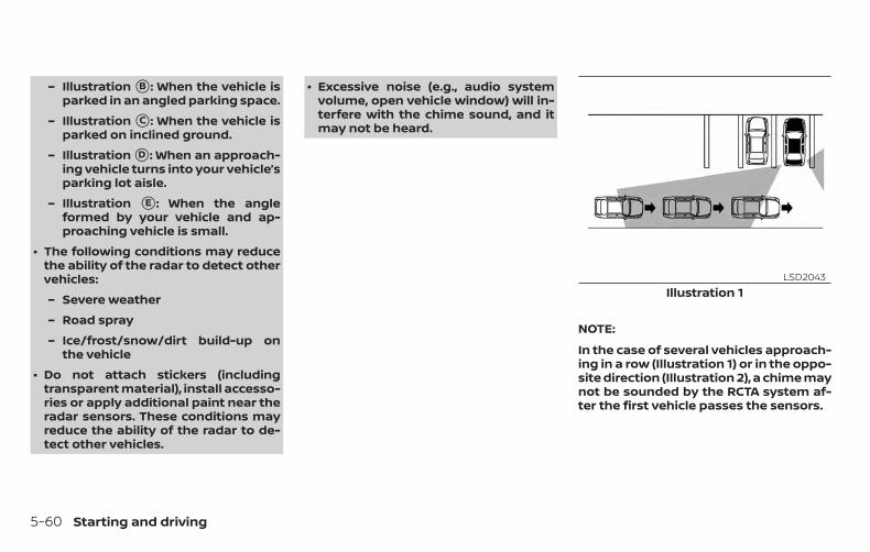
– Illustration �B : When the vehicle isparked in an angled parking space.
– Illustration �C : When the vehicle isparked on inclined ground.
– Illustration �D : When an approach-ing vehicle turns into your vehicle’sparking lot aisle.
– Illustration �E : When the angleformed by your vehicle and ap-proaching vehicle is small.
∙ The following conditions may reducethe ability of the radar to detect othervehicles:
– Severe weather
– Road spray
– Ice/frost/snow/dirt build-up onthe vehicle
∙ Do not attach stickers (includingtransparent material), install accesso-ries or apply additional paint near theradar sensors. These conditions mayreduce the ability of the radar to de-tect other vehicles.
∙ Excessive noise (e.g., audio systemvolume, open vehicle window) will in-terfere with the chime sound, and itmay not be heard.
NOTE:
In the case of several vehicles approach-ing in a row (Illustration 1) or in the oppo-site direction (Illustration 2), a chime maynot be sounded by the RCTA system af-ter the first vehicle passes the sensors.
Illustration 1LSD2043
5-60 Starting and driving
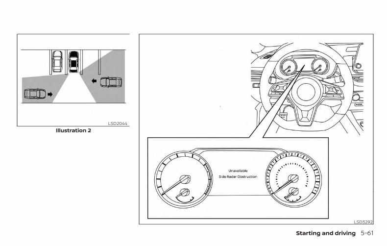
Illustration 2LSD2044
LSD3292
Starting and driving 5-61
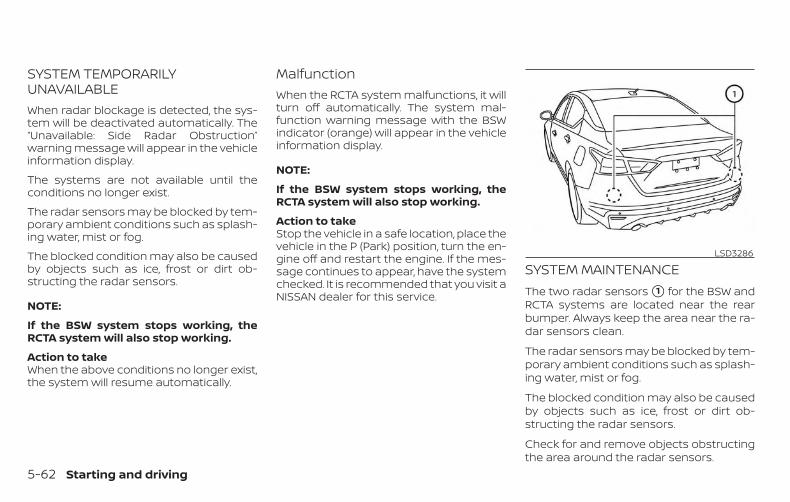
SYSTEM TEMPORARILYUNAVAILABLEWhen radar blockage is detected, the sys-tem will be deactivated automatically. The“Unavailable: Side Radar Obstruction”warning message will appear in the vehicleinformation display.
The systems are not available until theconditions no longer exist.
The radar sensors may be blocked by tem-porary ambient conditions such as splash-ing water, mist or fog.
The blocked condition may also be causedby objects such as ice, frost or dirt ob-structing the radar sensors.
NOTE:
If the BSW system stops working, theRCTA system will also stop working.
Action to takeWhen the above conditions no longer exist,the system will resume automatically.
MalfunctionWhen the RCTA system malfunctions, it willturn off automatically. The system mal-function warning message with the BSWindicator (orange) will appear in the vehicleinformation display.
NOTE:
If the BSW system stops working, theRCTA system will also stop working.
Action to takeStop the vehicle in a safe location, place thevehicle in the P (Park) position, turn the en-gine off and restart the engine. If the mes-sage continues to appear, have the systemchecked. It is recommended that you visit aNISSAN dealer for this service.
SYSTEM MAINTENANCEThe two radar sensors �1 for the BSW andRCTA systems are located near the rearbumper. Always keep the area near the ra-dar sensors clean.
The radar sensors may be blocked by tem-porary ambient conditions such as splash-ing water, mist or fog.
The blocked condition may also be causedby objects such as ice, frost or dirt ob-structing the radar sensors.
Check for and remove objects obstructingthe area around the radar sensors.
LSD3286
5-62 Starting and driving
Do not attach stickers (including transpar-ent material), install accessories or applyadditional paint near the radar sensors.
Do not strike or damage the area aroundthe radar sensors. It is recommended thatyou visit a NISSAN dealer if the area aroundthe radar sensors is damaged due to acollision.
Radio frequency statementNOTICE:
This device complies with Part 15 of the FCCRules.
Operation is subject to the following twoconditions:
this device may not cause harmful interfer-ence, and
this device must accept any interferencereceived, including interference that maycause undesired operation.
Changes or modifications made to thisequipment not expressly approved by(manufacturer name) may void the FCCauthorization to operate this equipment.
NOTE:
This equipment has been tested andfound to comply with the limits for aClass B digital device, pursuant to Part 15of the FCC Rules. These limits are de-signed to provide reasonable protectionagainst harmful interference in a resi-dential installation. This equipment gen-erates, uses and can radiate radio fre-quency energy and, if not installed andused in accordance with the instruc-tions, may cause harmful interference toradio communications. However, there isno guarantee that interference will notoccur in a particular installation. If thisequipment does cause harmful interfer-ence to radio or television reception,which can be determined by turning theequipment off and on, the user is en-couraged to try to correct the interfer-ence by one or more of the followingmeasures:
Reorient or relocate the receiving an-tenna.
Increase the separation between theequipment and receiver.
Connect the equipment into an outlet ona circuit different from that to which thereceiver is connected.
Consult the dealer or an experiencedradio/TV technician for help.
Starting and driving 5-63
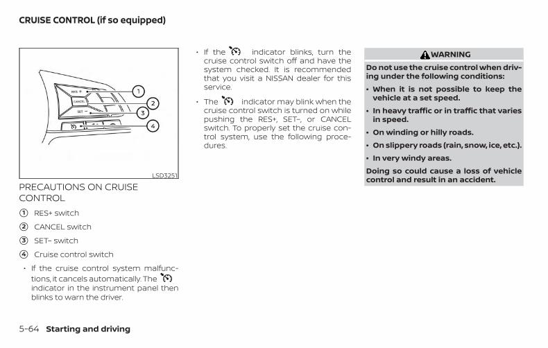
PRECAUTIONS ON CRUISECONTROL
�1 RES+ switch
�2 CANCEL switch
�3 SET– switch
�4 Cruise control switch
∙ If the cruise control system malfunc-tions, it cancels automatically. Theindicator in the instrument panel thenblinks to warn the driver.
∙ If the indicator blinks, turn thecruise control switch off and have thesystem checked. It is recommendedthat you visit a NISSAN dealer for thisservice.
∙ The indicator may blink when thecruise control switch is turned on whilepushing the RES+, SET–, or CANCELswitch. To properly set the cruise con-trol system, use the following proce-dures.
WARNINGDo not use the cruise control when driv-ing under the following conditions:
∙ When it is not possible to keep thevehicle at a set speed.
∙ In heavy traffic or in traffic that variesin speed.
∙ On winding or hilly roads.
∙ On slippery roads (rain, snow, ice, etc.).
∙ In very windy areas.
Doing so could cause a loss of vehiclecontrol and result in an accident.LSD3251
CRUISE CONTROL (if so equipped)
5-64 Starting and driving
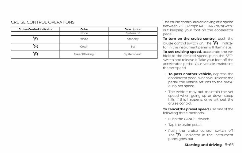
CRUISE CONTROL OPERATIONSCruise Control Indicator Color Description
None System off
White Standby
Green Set
Green(Blinking) System fault
The cruise control allows driving at a speedbetween 25 - 89 mph (40 - 144 km/h) with-out keeping your foot on the acceleratorpedal.To turn on the cruise control, push thecruise control switch on. The indica-tor in the instrument panel will illuminate.To set cruising speed, accelerate the ve-hicle to the desired speed, push the SET–switch and release it. Take your foot off theaccelerator pedal. Your vehicle maintainsthe set speed.
∙ To pass another vehicle, depress theaccelerator pedal. When you release thepedal, the vehicle returns to the previ-ously set speed.
∙ The vehicle may not maintain the setspeed when going up or down steephills. If this happens, drive without thecruise control.
To cancel the preset speed, use one of thefollowing three methods:
∙ Push the CANCEL switch.
∙ Tap the brake pedal.
∙ Push the cruise control switch off.The indicator in the instrumentpanel goes out.
Starting and driving 5-65
The cruise control is automatically can-celed if:
∙ You depress the brake pedal whilepushing the RES+ or SET– switch. Thepreset speed is deleted from memory.
∙ The vehicle slows down more than8 mph (13 km/h) below the set speed.
∙ You move the shift lever to N (Neutral).
To reset at a faster cruising speed, useone of the following three methods:
∙ Depress the accelerator pedal. Whenthe vehicle attains the desired speed,push and release the SET– switch.
∙ Push and hold the RES+ switch. Whenthe vehicle attains the speed you desire,release the switch.
∙ Push and release the RES+ switch. Eachtime you do this, the set speed in-creases by about 1 mph (1.6 km/h).
To reset at a slower cruising speed, useone of the following three methods:
∙ Lightly tap the brake pedal. When thevehicle attains the desired speed, pushthe SET– switch and release it.
∙ Push and hold the SET– switch. Releasethe switch when the vehicle slows tothe desired speed.
∙ Push and release the SET– switch. Eachtime you do this, the set speed de-creases by about 1 mph (1.6 km/h).
To resume the preset speed, push andrelease the RES+ switch. The vehicle re-turns to the last set cruising speed whenthe vehicle speed is over 25 mph (40 km/h).
To turn off the cruise control, use one ofthe following three methods:
∙ Push the CANCEL switch.
∙ Tap the brake pedal.
∙ Push the cruise control switch off.The indicator in the instrumentpanel goes out.
5-66 Starting and driving
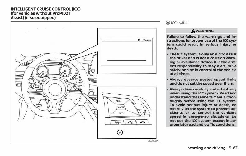
�A ICC switch
WARNINGFailure to follow the warnings and in-structions for proper use of the ICC sys-tem could result in serious injury ordeath.
∙ The ICC system is only an aid to assistthe driver and is not a collision warn-ing or avoidance device. It is the driv-er’s responsibility to stay alert, drivesafely, and be in control of the vehicleat all times.
∙ Always observe posted speed limitsand do not set the speed over them.
∙ Always drive carefully and attentivelywhen using the ICC system. Read andunderstand the Owner’s Manual thor-oughly before using the ICC system.To avoid serious injury or death, donot rely on the system to prevent ac-cidents or to control the vehicle’sspeed in emergency situations. Donot use the ICC system except in ap-propriate road and traffic conditions.
LSD3294
INTELLIGENT CRUISE CONTROL (ICC)(for vehicles without ProPILOTAssist) (if so equipped)
Starting and driving 5-67
∙ In the conventional (fixed speed)cruise control mode, a warning chimewill not sound to warn you if you aretoo close to the vehicle ahead. Payspecial attention to the distance be-tween your vehicle and the vehicleahead of you or a collision could occur.
NOTE:
For vehicles equipped with ProPILOTAssist, refer to “ProPILOT Assist” in thissection.
The ICC system maintains a selected dis-tance from the vehicle in front of you withinthe speed range of 0 to 90 mph (0 to144 km/h) up to the set speed. The setspeed can be selected by the driver be-tween 20 to 90 mph (32 to 144 km/h).
The vehicle travels at a set speed when theroad ahead is clear.
The ICC system can be set to one of twocruise control modes:
∙ Vehicle-to-vehicle distance controlmode: For maintaining a selected dis-tance between your vehicle and the ve-hicle in front of you up to the presetspeed
∙ Conventional (fixed speed) cruisecontrol mode: For cruising at a presetspeed
Push the ICC switch �A to choose thecruise control mode between the vehicle-to-vehicle distance control mode and theconventional (fixed speed) cruise controlmode.
Once a control mode is activated, it cannotbe changed to the other cruise controlmode. To change the mode, push the ICCswitch �A once to turn the system off. Thenpush the ICC switch �A again to turn thesystem back on and select the desiredcruise control mode.
Always confirm the setting in the ICC sys-tem display.
For the vehicle-to-vehicle distance controlmode, refer to “Vehicle-to-vehicle distancecontrol mode” in this section.
For the conventional (fixed speed) cruisecontrol mode, refer to “Conventional (fixedspeed) cruise control mode” in this section.
5-68 Starting and driving
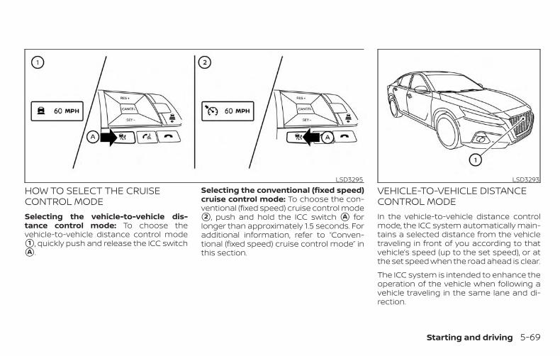
HOW TO SELECT THE CRUISECONTROL MODESelecting the vehicle-to-vehicle dis-tance control mode: To choose thevehicle-to-vehicle distance control mode�1 , quickly push and release the ICC switch�A .
Selecting the conventional (fixed speed)cruise control mode: To choose the con-ventional (fixed speed) cruise control mode�2 , push and hold the ICC switch �A forlonger than approximately 1.5 seconds. Foradditional information, refer to “Conven-tional (fixed speed) cruise control mode” inthis section.
VEHICLE-TO-VEHICLE DISTANCECONTROL MODEIn the vehicle-to-vehicle distance controlmode, the ICC system automatically main-tains a selected distance from the vehicletraveling in front of you according to thatvehicle’s speed (up to the set speed), or atthe set speed when the road ahead is clear.
The ICC system is intended to enhance theoperation of the vehicle when following avehicle traveling in the same lane and di-rection.
LSD3295 LSD3293
Starting and driving 5-69
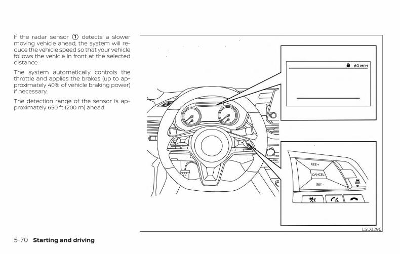
If the radar sensor �1 detects a slowermoving vehicle ahead, the system will re-duce the vehicle speed so that your vehiclefollows the vehicle in front at the selecteddistance.
The system automatically controls thethrottle and applies the brakes (up to ap-proximately 40% of vehicle braking power)if necessary.
The detection range of the sensor is ap-proximately 650 ft (200 m) ahead.
LSD3296
5-70 Starting and driving
VEHICLE-TO-VEHICLE DISTANCECONTROL MODE OPERATIONThe vehicle-to-vehicle distance controlmode is designed to maintain a selecteddistance from the vehicle in front of youand can reduce the speed to match aslower vehicle ahead. The system will de-celerate the vehicle as necessary and if thevehicle ahead comes to a stop, the vehicledecelerates to a standstill. However, the ICCsystem can only apply up to 40% of thevehicle’s total braking power.
This system should only be used when trafficconditions allow vehicle speeds to remainfairly constant or when vehicle speedschange gradually. If a vehicle moves into thetraveling lane ahead or if a vehicle travelingahead rapidly decelerates, the distance be-tween vehicles may become closer becausethe ICC system cannot decelerate the ve-hicle quickly enough. If this occurs, the ICCsystem will sound a warning chime and blinkthe system display to notify the driver to takenecessary action.
The system will cancel and a warningchime will sound if the speed is below ap-proximately 15 mph (24 km/h) and a vehicleis not detected ahead. The system will also
disengage when the vehicle goes abovethe maximum set speed.
For additional information, refer to “Ap-proach warning” in this section.
The following items are controlled in thevehicle-to-vehicle distance control mode:
∙ When there are no vehicles travelingahead, the vehicle-to-vehicle distancecontrol mode maintains the speed setby the driver. The set speed range isbetween approximately 20 and 90 mph(32 and 144 km/h).
∙ When there is a vehicle traveling ahead,the vehicle-to-vehicle distance controlmode adjusts the speed to maintainthe distance, selected by the driver,from the vehicle ahead. If the vehicleahead comes to a stop, the vehicle de-celerates to a standstill within the limi-tations of the system. The system willcancel once it judges a standstill with awarning chime.
∙ When the vehicle traveling ahead hasmoved out from its lane of travel, thevehicle-to-vehicle distance controlmode accelerates and maintains ve-hicle speed up to the set speed.
The ICC system does not control vehiclespeed or warn you when you approachstationary and slow moving vehicles. Youmust pay attention to vehicle operation tomaintain proper distance from vehiclesahead when approaching toll gates or traf-fic congestion.
Starting and driving 5-71
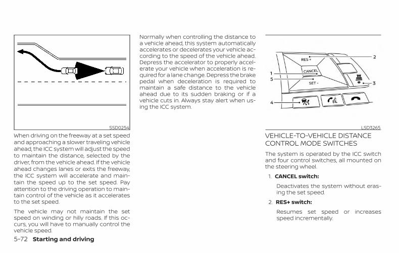
When driving on the freeway at a set speedand approaching a slower traveling vehicleahead, the ICC system will adjust the speedto maintain the distance, selected by thedriver, from the vehicle ahead. If the vehicleahead changes lanes or exits the freeway,the ICC system will accelerate and main-tain the speed up to the set speed. Payattention to the driving operation to main-tain control of the vehicle as it acceleratesto the set speed.
The vehicle may not maintain the setspeed on winding or hilly roads. If this oc-curs, you will have to manually control thevehicle speed.
Normally when controlling the distance toa vehicle ahead, this system automaticallyaccelerates or decelerates your vehicle ac-cording to the speed of the vehicle ahead.Depress the accelerator to properly accel-erate your vehicle when acceleration is re-quired for a lane change. Depress the brakepedal when deceleration is required tomaintain a safe distance to the vehicleahead due to its sudden braking or if avehicle cuts in. Always stay alert when us-ing the ICC system.
VEHICLE-TO-VEHICLE DISTANCECONTROL MODE SWITCHESThe system is operated by the ICC switchand four control switches, all mounted onthe steering wheel.
1. CANCEL switch:
Deactivates the system without eras-ing the set speed.
2. RES+ switch:
Resumes set speed or increasesspeed incrementally.
SSD0254 LSD3265
5-72 Starting and driving
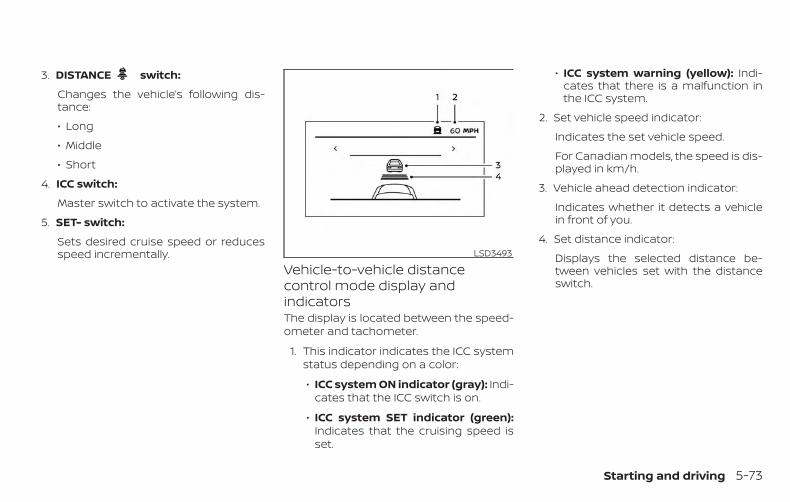
3. DISTANCE switch:
Changes the vehicle’s following dis-tance:
∙ Long
∙ Middle
∙ Short
4. ICC switch:
Master switch to activate the system.
5. SET- switch:
Sets desired cruise speed or reducesspeed incrementally.
Vehicle-to-vehicle distancecontrol mode display andindicatorsThe display is located between the speed-ometer and tachometer.
1. This indicator indicates the ICC systemstatus depending on a color:
∙ ICC system ON indicator (gray): Indi-cates that the ICC switch is on.
∙ ICC system SET indicator (green):Indicates that the cruising speed isset.
∙ ICC system warning (yellow): Indi-cates that there is a malfunction inthe ICC system.
2. Set vehicle speed indicator:
Indicates the set vehicle speed.
For Canadian models, the speed is dis-played in km/h.
3. Vehicle ahead detection indicator:
Indicates whether it detects a vehiclein front of you.
4. Set distance indicator:
Displays the selected distance be-tween vehicles set with the distanceswitch.
LSD3493
Starting and driving 5-73
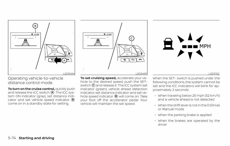
Operating vehicle-to-vehicledistance control modeTo turn on the cruise control, quickly pushand release the ICC switch �A . The ICC sys-tem ON indicator (gray), set distance indi-cator and set vehicle speed indicator �Bcome on in a standby state for setting.
To set cruising speed, accelerate your ve-hicle to the desired speed, push the SET–switch �C and release it. The ICC system setindicator (green), vehicle ahead detectionindicator, set distance indicator and set ve-hicle speed indicator �B will come on. Takeyour foot off the accelerator pedal. Yourvehicle will maintain the set speed.
When the SET– switch is pushed under thefollowing conditions, the system cannot beset and the ICC indicators will blink for ap-proximately 2 seconds:
∙ When traveling below 20 mph (32 km/h)and a vehicle ahead is not detected
∙ When the shift lever is not in the D (Drive)or Manual mode
∙ When the parking brake is applied
∙ When the brakes are operated by thedriver
LSD3494 LSD3495 LSD3102
5-74 Starting and driving
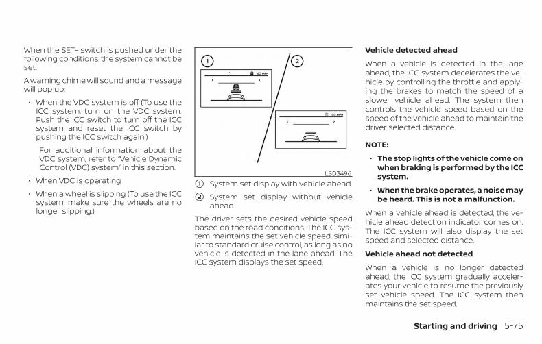
When the SET– switch is pushed under thefollowing conditions, the system cannot beset.
A warning chime will sound and a messagewill pop up:
∙ When the VDC system is off (To use theICC system, turn on the VDC system.Push the ICC switch to turn off the ICCsystem and reset the ICC switch bypushing the ICC switch again.)
For additional information about theVDC system, refer to “Vehicle DynamicControl (VDC) system” in this section.
∙ When VDC is operating
∙ When a wheel is slipping (To use the ICCsystem, make sure the wheels are nolonger slipping.)
�1 System set display with vehicle ahead
�2 System set display without vehicleahead
The driver sets the desired vehicle speedbased on the road conditions. The ICC sys-tem maintains the set vehicle speed, simi-lar to standard cruise control, as long as novehicle is detected in the lane ahead. TheICC system displays the set speed.
Vehicle detected ahead
When a vehicle is detected in the laneahead, the ICC system decelerates the ve-hicle by controlling the throttle and apply-ing the brakes to match the speed of aslower vehicle ahead. The system thencontrols the vehicle speed based on thespeed of the vehicle ahead to maintain thedriver selected distance.
NOTE:
∙ The stop lights of the vehicle come onwhen braking is performed by the ICCsystem.
∙ When the brake operates, a noise maybe heard. This is not a malfunction.
When a vehicle ahead is detected, the ve-hicle ahead detection indicator comes on.The ICC system will also display the setspeed and selected distance.
Vehicle ahead not detected
When a vehicle is no longer detectedahead, the ICC system gradually acceler-ates your vehicle to resume the previouslyset vehicle speed. The ICC system thenmaintains the set speed.
LSD3496
Starting and driving 5-75
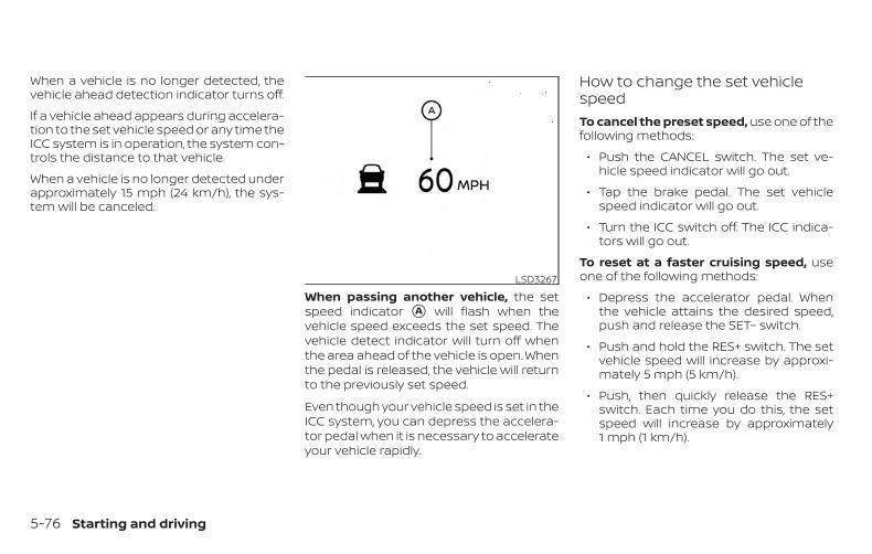
When a vehicle is no longer detected, thevehicle ahead detection indicator turns off.
If a vehicle ahead appears during accelera-tion to the set vehicle speed or any time theICC system is in operation, the system con-trols the distance to that vehicle.
When a vehicle is no longer detected underapproximately 15 mph (24 km/h), the sys-tem will be canceled.
When passing another vehicle, the setspeed indicator �A will flash when thevehicle speed exceeds the set speed. Thevehicle detect indicator will turn off whenthe area ahead of the vehicle is open. Whenthe pedal is released, the vehicle will returnto the previously set speed.
Even though your vehicle speed is set in theICC system, you can depress the accelera-tor pedal when it is necessary to accelerateyour vehicle rapidly.
How to change the set vehiclespeedTo cancel the preset speed, use one of thefollowing methods:
∙ Push the CANCEL switch. The set ve-hicle speed indicator will go out.
∙ Tap the brake pedal. The set vehiclespeed indicator will go out.
∙ Turn the ICC switch off. The ICC indica-tors will go out.
To reset at a faster cruising speed, useone of the following methods:
∙ Depress the accelerator pedal. Whenthe vehicle attains the desired speed,push and release the SET– switch.
∙ Push and hold the RES+ switch. The setvehicle speed will increase by approxi-mately 5 mph (5 km/h).
∙ Push, then quickly release the RES+switch. Each time you do this, the setspeed will increase by approximately1 mph (1 km/h).
LSD3267
5-76 Starting and driving
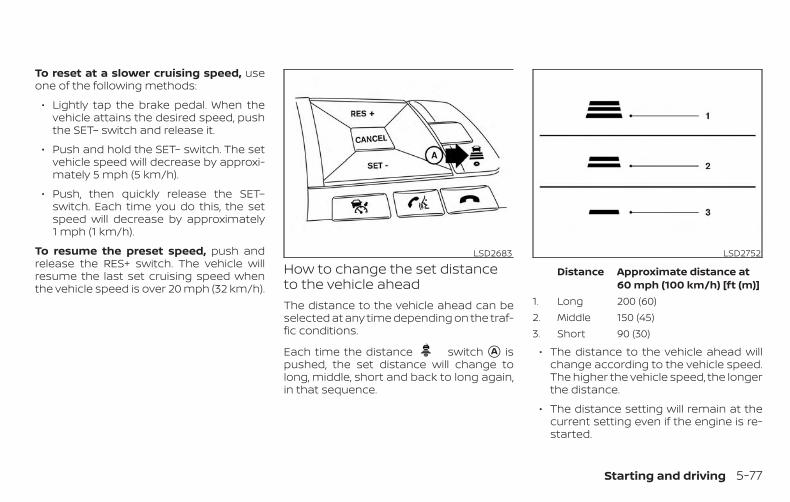
To reset at a slower cruising speed, useone of the following methods:
∙ Lightly tap the brake pedal. When thevehicle attains the desired speed, pushthe SET– switch and release it.
∙ Push and hold the SET– switch. The setvehicle speed will decrease by approxi-mately 5 mph (5 km/h).
∙ Push, then quickly release the SET–switch. Each time you do this, the setspeed will decrease by approximately1 mph (1 km/h).
To resume the preset speed, push andrelease the RES+ switch. The vehicle willresume the last set cruising speed whenthe vehicle speed is over 20 mph (32 km/h).
How to change the set distanceto the vehicle aheadThe distance to the vehicle ahead can beselected at any time depending on the traf-fic conditions.
Each time the distance switch �A ispushed, the set distance will change tolong, middle, short and back to long again,in that sequence.
Distance Approximate distance at60 mph (100 km/h) [ft (m)]
1. Long 200 (60)2. Middle 150 (45)3. Short 90 (30)
∙ The distance to the vehicle ahead willchange according to the vehicle speed.The higher the vehicle speed, the longerthe distance.
∙ The distance setting will remain at thecurrent setting even if the engine is re-started.
LSD2683 LSD2752
Starting and driving 5-77
Approach warningIf your vehicle comes closer to the vehicleahead due to rapid deceleration of thatvehicle or if another vehicle cuts in, the sys-tem warns the driver with the chime andICC system display. Decelerate by depress-ing the brake pedal to maintain a safe ve-hicle distance if:
∙ The chime sounds.
∙ The vehicle ahead detection indicatorblinks.
The warning chime may not sound insome cases when there is a short distancebetween vehicles. Some examples are:
∙ When the vehicles are traveling at thesame speed and the distance betweenvehicles is not changing.
∙ When the vehicle ahead is travelingfaster and the distance between ve-hicles is increasing.
∙ When a vehicle cuts in near your vehicle.
The warning chime will not sound when:
∙ The vehicle approaches other vehiclesthat are parked or moving slowly.
∙ The accelerator pedal is depressed,overriding the system.
NOTE:
The approach warning chime may soundand the system display may blink whenthe ICC sensor detects objects on theside of the vehicle or on the side of theroad. This may cause the ICC system todecelerate or accelerate the vehicle. TheICC sensor may detect these objectswhen the vehicle is driven on windingroads, narrow roads, hilly roads, or whenentering or exiting a curve. In thesecases you will have to manually controlthe proper distance ahead of your ve-hicle.
Also, the sensor sensitivity can be affectedby vehicle operation (steering maneuver ordriving position in the lane) or traffic or ve-hicle condition (for example, if a vehicle isbeing driven with some damage).
Automatic cancellationA chime sounds under the following condi-tions and the control is automatically can-celed:
∙ When the vehicle ahead is not detectedand your vehicle is traveling below thespeed of 15 mph (24 km/h)
∙ When the system judges the vehicle isat a standstill
∙ When the shift lever is not in the D (Drive)position, Manual mode or L (Low) range.
∙ When the parking brake system is ap-plied
∙ When the VDC system is turned off
∙ When VDC operates
∙ When distance measurement becomesimpaired due to adhesion of dirt or ob-struction to the sensor
∙ When a wheel slips
∙ When the radar signal is temporarily in-terrupted
5-78 Starting and driving
VEHICLE-TO-VEHICLE DISTANCECONTROL MODE LIMITATIONS
WARNINGListed below are the system limitationsfor the ICC system. Failure to operatethe vehicle in accordance with thesesystem limitations could result in seri-ous injury or death.
∙ The ICC system is primarily intendedfor use on straight, dry, open roadswith light traffic. It is not advisable touse the ICC system in city traffic orcongested areas.
∙ The ICC system will not adapt auto-matically to road conditions. This sys-tem should be used in evenly flowingtraffic. Do not use the system on roadswith sharp curves, or on icy roads, inheavy rain or in fog.
∙ As there is a performance limit to thedistance control function, never relysolely on the ICC system. This systemdoes not correct careless, inattentiveor absentminded driving, or over-come poor visibility in rain, fog, orother bad weather. Decelerate the ve-hicle speed by depressing the brakepedal, depending on the distance tothe vehicle ahead and the surround-ing circumstances in order to main-tain a safe distance between vehicles.
∙ If the vehicle ahead comes to a stop,the vehicle decelerates to a standstillwithin the limitations of the system.The system will cancel once it judgesthat the vehicle has come to a stand-still and sound a warning chime. Toprevent the vehicle from moving, thedriver must depress the brake pedal.
∙ Always pay attention to the operationof the vehicle and be ready to manu-ally control the proper following dis-tance. The ICC system may not be ableto maintain the selected distance be-tween vehicles (following distance) orselected vehicle speed under somecircumstances.
∙ The system may not detect the ve-hicle in front of you in certain road orweather conditions. To avoid acci-dents, never use the ICC system underthe following conditions:
– On roads where the traffic is heavyor there are sharp curves
– On slippery road surfaces such ason ice or snow, etc.
– During bad weather (rain, fog,snow, etc.)
– When rain, snow or dirt adhere tothe bumper around the distancesensor
– On steep downhill roads (the vehiclemay go beyond the set vehiclespeed and frequent braking may re-sult in overheating the brakes)
– On repeated uphill and downhillroads
– When traffic conditions make it dif-ficult to keep a proper distance be-tween vehicles because of fre-quent acceleration or deceleration
– Interference by other radar sources
Starting and driving 5-79
∙ Do not use the ICC system if you aretowing a trailer. The system may notdetect a vehicle ahead.
∙ In some road or traffic conditions, avehicle or object can unexpectedlycome into the sensor detection zoneand cause automatic braking. Alwaysstay alert and avoid using the ICC sys-tem where not recommended in thiswarning section.
The radar sensor will not detect the follow-ing objects:
∙ Stationary and slow moving vehicles
∙ Pedestrians or objects in the roadway
∙ Oncoming vehicles in the same lane
∙ Motorcycles traveling offset in the travellane
The sensor generally detects the signalsreturned from the vehicle ahead. Therefore,if the sensor cannot detect the reflectionfrom the vehicle ahead, the ICC systemmay not maintain the selected distance.
The following are some conditions in whichthe sensor cannot properly detect a ve-hicle ahead and the system may not oper-ate properly:
∙ When snow or road spray from travelingvehicles reduces the sensor’s detection.
∙ When your vehicle is towing a trailer, etc.
∙ When excessively heavy baggage isloaded in the rear seat or cargo area ofyour vehicle.
The ICC system is designed to automati-cally check the sensor’s operation withinthe limitations of the system.
When the sensor is covered with dirt or isobstructed, the system will automaticallybe canceled. If the sensor is covered withice, a transparent or translucent vinyl bag,etc., the ICC system may not detect them.In these instances, the vehicle-to-vehicledistance control mode may not cancel andmay not be able to maintain the selectedfollowing distance from the vehicle ahead.Be sure to check and clean the sensorregularly.
The detection zone of the radar sensor islimited. A vehicle ahead must be in the de-tection zone for the vehicle-to-vehicle dis-tance detection mode to maintain the se-lected distance from the vehicle ahead.
A vehicle ahead may move outside of thedetection zone due to its position withinthe same lane of travel. Motorcycles maynot be detected in the same lane ahead ifthey are traveling offset from the centerlineof the lane. A vehicle that is entering thelane ahead may not be detected until thevehicle has completely moved into thelane.
If this occurs, the ICC system may warnyou by blinking the system indicator andsounding the chime. The driver mayhave to manually control the proper dis-tance away from vehicle traveling ahead.
5-80 Starting and driving
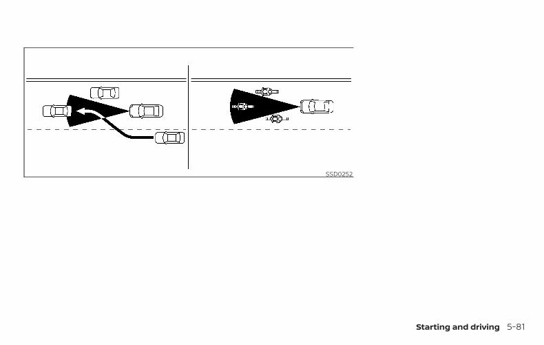
SSD0252
Starting and driving 5-81
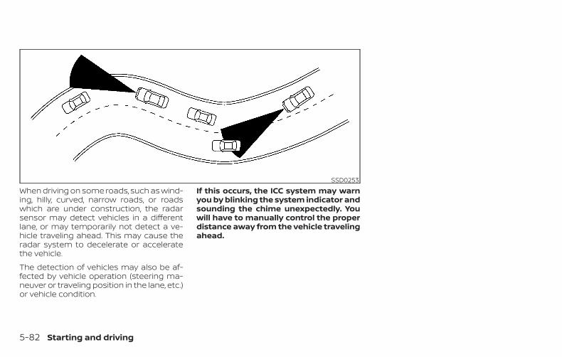
When driving on some roads, such as wind-ing, hilly, curved, narrow roads, or roadswhich are under construction, the radarsensor may detect vehicles in a differentlane, or may temporarily not detect a ve-hicle traveling ahead. This may cause theradar system to decelerate or acceleratethe vehicle.
The detection of vehicles may also be af-fected by vehicle operation (steering ma-neuver or traveling position in the lane, etc.)or vehicle condition.
If this occurs, the ICC system may warnyou by blinking the system indicator andsounding the chime unexpectedly. Youwill have to manually control the properdistance away from the vehicle travelingahead.
SSD0253
5-82 Starting and driving
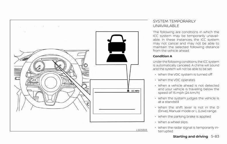
SYSTEM TEMPORARILYUNAVAILABLEThe following are conditions in which theICC system may be temporarily unavail-able. In these instances, the ICC systemmay not cancel and may not be able tomaintain the selected following distancefrom the vehicle ahead.
Condition A
Under the following conditions, the ICC systemis automatically canceled. A chime will soundand the system will not be able to be set:
∙ When the VDC system is turned off
∙ When the VDC operates
∙ When a vehicle ahead is not detectedand your vehicle is traveling below thespeed of 15 mph (24 km/h)
∙ When the system judges the vehicle isat a standstill
∙ When the shift lever is not in the D(Drive), Manual mode or L (Low) range.
∙ When the parking brake is applied
∙ When a wheel slips
∙ When the radar signal is temporarily in-terruptedLSD3303
Starting and driving 5-83
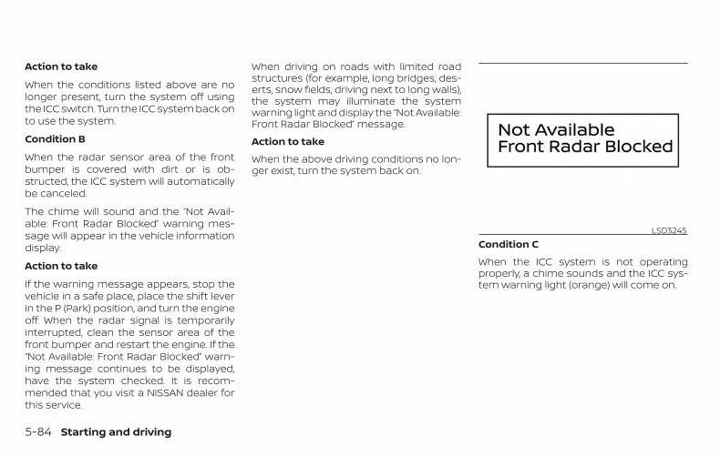
Action to take
When the conditions listed above are nolonger present, turn the system off usingthe ICC switch. Turn the ICC system back onto use the system.
Condition B
When the radar sensor area of the frontbumper is covered with dirt or is ob-structed, the ICC system will automaticallybe canceled.
The chime will sound and the “Not Avail-able: Front Radar Blocked” warning mes-sage will appear in the vehicle informationdisplay.
Action to take
If the warning message appears, stop thevehicle in a safe place, place the shift leverin the P (Park) position, and turn the engineoff. When the radar signal is temporarilyinterrupted, clean the sensor area of thefront bumper and restart the engine. If the“Not Available: Front Radar Blocked” warn-ing message continues to be displayed,have the system checked. It is recom-mended that you visit a NISSAN dealer forthis service.
When driving on roads with limited roadstructures (for example, long bridges, des-erts, snow fields, driving next to long walls),the system may illuminate the systemwarning light and display the “Not Available:Front Radar Blocked” message.
Action to take
When the above driving conditions no lon-ger exist, turn the system back on.
Condition C
When the ICC system is not operatingproperly, a chime sounds and the ICC sys-tem warning light (orange) will come on.
LSD3245
5-84 Starting and driving
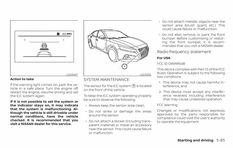
Action to take
If the warning light comes on, park the ve-hicle in a safe place. Turn the engine off,restart the engine, resume driving and setthe ICC system again.
If it is not possible to set the system orthe indicator stays on, it may indicatethat the system is malfunctioning. Al-though the vehicle is still drivable undernormal conditions, have the vehiclechecked. It is recommended that youvisit a NISSAN dealer for this service.
SYSTEM MAINTENANCEThe sensor for the ICC system �1 is locatedon the front of the vehicle.
To keep the ICC system operating properly,be sure to observe the following:
∙ Always keep the sensor area clean.
∙ Do not strike or damage the areasaround the sensor.
∙ Do not attach a sticker (including trans-parent material) or install an accessorynear the sensor. This could cause failureor malfunction.
∙ Do not attach metallic objects near thesensor area (brush guard, etc.). Thiscould cause failure or malfunction.
∙ Do not alter, remove, or paint the frontbumper. Before customizing or restor-ing the front bumper, it is recom-mended that you visit a NISSAN dealer.
Radio frequency statementFor USA
FCC ID OAYARS4B
This device complies with Part 15 of the FCCRules. Operation is subject to the followingtwo conditions:
1. This device may not cause harmful in-terference, and
2. This device must accept any interfer-ence received, including interferencethat may cause undesired operation.
FCC Warning
Changes or modifications not expresslyapproved by the party responsible forcompliance could void the user’s authorityto operate the equipment.
LSD3497 LSD3293
Starting and driving 5-85
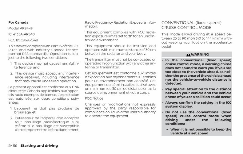
For Canada
Model: ARS4–B
IC: 4135A-ARS4B
FCC ID: OAYARS4B
This device complies with Part 15 of the FCCRules and with Industry Canada licence-exempt RSS standard(s). Operation is sub-ject to the following two conditions:
1. This device may not cause harmful in-terference, and
2. This device must accept any interfer-ence received, including interferencethat may cause undesired operation.
Le présent appareil est conforme aux CNRd’Industrie Canada applicables aux appar-eils radio exempts de licence. L’exploitationest autorisée aux deux conditions suiv-antes:
1. L’appareil ne doit pas produire debrouillage, et
2. L’utilisateur de l’appareil doit acceptertout brouillage radioélectrique subi,même si le brouillage est susceptibled’en compromettre le fonctionnement.
Radio Frequency Radiation Exposure Infor-mation:
This equipment complies with FCC radia-tion exposure limits set forth for an uncon-trolled environment.
This equipment should be installed andoperated with minimum distance of 30 cmbetween the radiator and your body.
The transmitter must not be co-located oroperating in conjunction with any other an-tenna or transmitter.
Cet équipement est conforme aux limitesd’exposition aux rayonnements IC établiespour un environnement non contrôlé. Cetéquipement doit être installé et utilisé avecun minimum de 30 cm de distance entre lasource de rayonnement et votre corps.
FCC Notice
Changes or modifications not expresslyapproved by the party responsible forcompliance could void the user’s authorityto operate the equipment.
CONVENTIONAL (fixed speed)CRUISE CONTROL MODEThis mode allows driving at a speed be-tween 25 to 90 mph (40 to 144 km/h) with-out keeping your foot on the acceleratorpedal.
WARNING∙ In the conventional (fixed speed)
cruise control mode, a warning chimedoes not sound to warn you if you aretoo close to the vehicle ahead, as nei-ther the presence of the vehicle aheadnor the vehicle-to-vehicle distance isdetected.
∙ Pay special attention to the distancebetween your vehicle and the vehicleahead of you or a collision could occur.
∙ Always confirm the setting in the ICCsystem display.
∙ Do not use the conventional (fixedspeed) cruise control mode whendriving under the followingconditions:
– When it is not possible to keep thevehicle at a set speed
5-86 Starting and driving
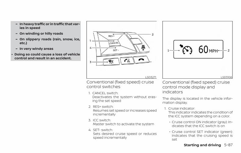
– In heavy traffic or in traffic that var-ies in speed
– On winding or hilly roads
– On slippery roads (rain, snow, ice,etc.)
– In very windy areas
∙ Doing so could cause a loss of vehiclecontrol and result in an accident.
Conventional (fixed speed) cruisecontrol switches
1. CANCEL switch:Deactivates the system without eras-ing the set speed
2. RES+ switch:Resumes set speed or increases speedincrementally
3. ICC switch:Master switch to activate the system
4. SET- switch:Sets desired cruise speed or reducesspeed incrementally
Conventional (fixed speed) cruisecontrol mode display andindicatorsThe display is located in the vehicle infor-mation display.
1. Cruise indicator:This indicator indicates the condition ofthe ICC system depending on a color.
∙ Cruise control ON indicator (gray): In-dicates that the ICC switch is on
∙ Cruise control SET indicator (green):Indicates that the cruising speed isset
LSD3271 LSD3106
Starting and driving 5-87
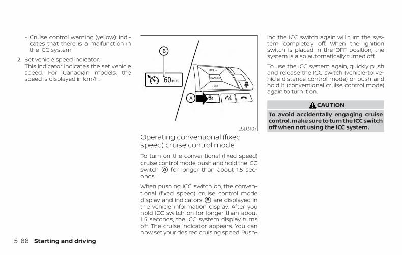
∙ Cruise control warning (yellow): Indi-cates that there is a malfunction inthe ICC system
2. Set vehicle speed indicator:This indicator indicates the set vehiclespeed. For Canadian models, thespeed is displayed in km/h.
Operating conventional (fixedspeed) cruise control modeTo turn on the conventional (fixed speed)cruise control mode, push and hold the ICCswitch �A for longer than about 1.5 sec-onds.
When pushing ICC switch on, the conven-tional (fixed speed) cruise control modedisplay and indicators �B are displayed inthe vehicle information display. After youhold ICC switch on for longer than about1.5 seconds, the ICC system display turnsoff. The cruise indicator appears. You cannow set your desired cruising speed. Push-
ing the ICC switch again will turn the sys-tem completely off. When the ignitionswitch is placed in the OFF position, thesystem is also automatically turned off.
To use the ICC system again, quickly pushand release the ICC switch (vehicle-to ve-hicle distance control mode) or push andhold it (conventional cruise control mode)again to turn it on.
CAUTIONTo avoid accidentally engaging cruisecontrol, make sure to turn the ICC switchoff when not using the ICC system.LSD3107
5-88 Starting and driving
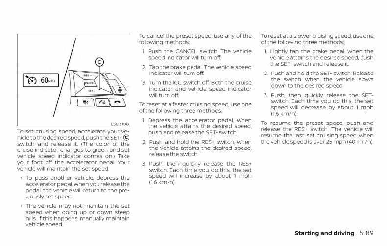
To set cruising speed, accelerate your ve-hicle to the desired speed, push the SET- �Cswitch and release it. (The color of thecruise indicator changes to green and setvehicle speed indicator comes on.) Takeyour foot off the accelerator pedal. Yourvehicle will maintain the set speed.
∙ To pass another vehicle, depress theaccelerator pedal. When you release thepedal, the vehicle will return to the pre-viously set speed.
∙ The vehicle may not maintain the setspeed when going up or down steephills. If this happens, manually maintainvehicle speed.
To cancel the preset speed, use any of thefollowing methods:
1. Push the CANCEL switch. The vehiclespeed indicator will turn off.
2. Tap the brake pedal. The vehicle speedindicator will turn off.
3. Turn the ICC switch off. Both the cruiseindicator and vehicle speed indicatorwill turn off.
To reset at a faster cruising speed, use oneof the following three methods:
1. Depress the accelerator pedal. Whenthe vehicle attains the desired speed,push and release the SET- switch.
2. Push and hold the RES+ switch. Whenthe vehicle attains the desired speed,release the switch.
3. Push, then quickly release the RES+switch. Each time you do this, the setspeed will increase by about 1 mph(1.6 km/h).
To reset at a slower cruising speed, use oneof the following three methods:
1. Lightly tap the brake pedal. When thevehicle attains the desired speed, pushthe SET- switch and release it.
2. Push and hold the SET- switch. Releasethe switch when the vehicle slowsdown to the desired speed.
3. Push, then quickly release the SET-switch. Each time you do this, the setspeed will decrease by about 1 mph(1.6 km/h).
To resume the preset speed, push andrelease the RES+ switch. The vehicle willresume the last set cruising speed whenthe vehicle speed is over 25 mph (40 km/h).
LSD3108
Starting and driving 5-89
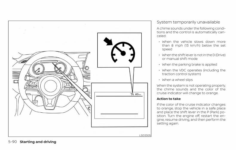
System temporarily unavailableA chime sounds under the following condi-tions and the control is automatically can-celed:
∙ When the vehicle slows down morethan 8 mph (13 km/h) below the setspeed
∙ When the shift lever is not in the D (Drive)or manual shift mode
∙ When the parking brake is applied
∙ When the VDC operates (including thetraction control system)
∙ When a wheel slips
When the system is not operating properly,the chime sounds and the color of thecruise indicator will change to orange.
Action to take
If the color of the cruise indicator changesto orange, stop the vehicle in a safe placeand place the shift lever in the P (Park) po-sition. Turn the engine off, restart the en-gine, resume driving, and then perform thesetting again.
LSD3305
5-90 Starting and driving
If it is not possible to set or the indicatorstays on, it may indicate that the systemis malfunctioning. Although the vehicleis still drivable under normal conditions,have the vehicle checked. It is recom-mended that you visit a NISSAN dealerfor this service.
WARNINGFailure to follow the warnings and in-structions for proper use of the ProPI-LOT Assist system could result in seri-ous injury or death.
∙ ProPILOT Assist is not a self-drivingsystem. Within the limits of its capa-bilities, as described in this manual, ithelps the driver with certain drivingactivities.
∙ The ProPILOT Assist system is not areplacement for proper driving proce-dures and is not designed to correctcareless, inattentive or absent-minded driving. ProPILOT Assist willnot always steer the vehicle to keep itin the lane. The ProPILOT Assist sys-tem is not designed to prevent loss ofcontrol. It is the driver’s responsibilityto stay alert, drive safely, keep the ve-hicle in the traveling lane, and be incontrol of the vehicle at all times.
∙ There are limitations to the ProPILOTAssist system capability. The ProPI-LOT Assist system does not functionin all driving, traffic, weather, and roadconditions. It is the driver’s responsi-bility to stay alert, drive safely, keepthe vehicle in the traveling lane, andbe in control of the vehicle at all times.
∙ The ProPILOT Assist system is only anaid to assist the driver and is not acollision warning or avoidance device.
∙ The ProPILOT Assist system is forhighway use only and is not intendedfor city driving. Failure to apply thebrakes or steer the vehicle when nec-essary may result in a seriousaccident.
∙ Always observe posted speed limitsand do not set the speed over them.
∙ Never take your hands off the steeringwheel when driving. Always keep yourhands on the steering wheel and driveyour vehicle safely.
∙ Never unfasten your safety belt whenusing ProPILOT Assist. Doing so auto-matically cancels the ProPILOT Assistsystem.
PROPILOT ASSIST (if so equipped)
Starting and driving 5-91
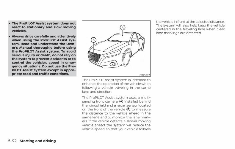
∙ The ProPILOT Assist system does notreact to stationary and slow movingvehicles.
∙ Always drive carefully and attentivelywhen using the ProPILOT Assist sys-tem. Read and understand the Own-er’s Manual thoroughly before usingthe ProPILOT Assist system. To avoidserious injury or death, do not rely onthe system to prevent accidents or tocontrol the vehicle’s speed in emer-gency situations. Do not use the Pro-PILOT Assist system except in appro-priate road and traffic conditions.
The ProPILOT Assist system is intended toenhance the operation of the vehicle whenfollowing a vehicle traveling in the samelane and direction.
The ProPILOT Assist system uses a multi-sensing front camera �A installed behindthe windshield and a radar sensor locatedon the front of the vehicle �B to measurethe distance to the vehicle ahead in thesame lane and to monitor the lane mark-ers. If the vehicle detects a slower movingvehicle ahead, the system will reduce thevehicle speed so that your vehicle follows
the vehicle in front at the selected distance.The system will also help keep the vehiclecentered in the traveling lane when clearlane markings are detected.
LSD3223
5-92 Starting and driving
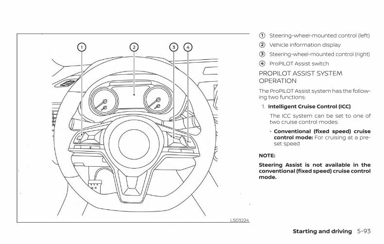
�1 Steering-wheel-mounted control (left)
�2 Vehicle information display
�3 Steering-wheel-mounted control (right)
�4 ProPILOT Assist switch
PROPILOT ASSIST SYSTEMOPERATIONThe ProPILOT Assist system has the follow-ing two functions:
1. Intelligent Cruise Control (ICC)
The ICC system can be set to one oftwo cruise control modes:
∙ Conventional (fixed speed) cruisecontrol mode: For cruising at a pre-set speed
NOTE:
Steering Assist is not available in theconventional (fixed speed) cruise controlmode.
LSD3224
Starting and driving 5-93
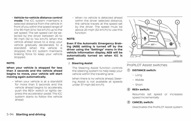
∙ Vehicle-to-vehicle distance controlmode: The ICC system maintains aselected distance from the vehicle infront of you within the speed range of0 to 90 mph (0 to 144 km/h) up to theset speed. The set speed can be se-lected by the driver between 20 to90 mph (32 to 144 km/h). When thevehicle ahead slows to a stop, yourvehicle gradually decelerates to astandstill. When the vehicle isstopped, the ICC system maintainsbraking force to keep your vehiclestopped.
NOTE:
When your vehicle is stopped for lessthan 3 seconds and the vehicle aheadbegins to move, your vehicle will startmoving again automatically.
– When your vehicle is at a standstillfor more than 3 seconds and thevehicle ahead begins to accelerate,push the RES+ switch or lightly de-press the accelerator pedal. The ICCsystem starts to follow the vehicleahead.
– When no vehicle is detected aheadwithin the driver selected distance,the vehicle travels at the speed setby the driver. The speed must beabove 20 mph (32 km/h) to use thisfunction.
NOTE:
Even if the Automatic Emergency Brak-ing (AEB) setting is turned off by thedriver using the “Settings” menu in thevehicle information display, AEB will beautomatically turned on when ICC isused.
2. Steering Assist
The Steering Assist function controlsthe steering system to help keep yourvehicle within the traveling lane.
When there is no vehicle ahead, Steer-ing Assist is not available at speedsunder 37 mph (60 km/h).
ProPILOT Assist switches
�1 DISTANCE switch:
– Long
– Middle
– Short
�2 RES+ switch:
Resumes set speed or increasesspeed incrementally
�3 CANCEL switch:
Deactivates the ProPILOT Assist system
LSD3225
5-94 Starting and driving
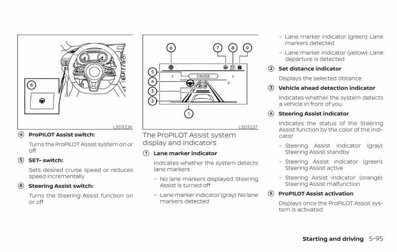
�4 ProPILOT Assist switch:
Turns the ProPILOT Assist system on oroff
�5 SET- switch:
Sets desired cruise speed or reducesspeed incrementally
�6 Steering Assist switch:
Turns the Steering Assist function onor off
The ProPILOT Assist systemdisplay and indicators�1 Lane marker indicator
Indicates whether the system detectslane markers
– No lane markers displayed: SteeringAssist is turned off
– Lane marker indicator (gray): No lanemarkers detected
– Lane marker indicator (green): Lanemarkers detected
– Lane marker indicator (yellow): Lanedeparture is detected
�2 Set distance indicator
Displays the selected distance
�3 Vehicle ahead detection indicator
Indicates whether the system detectsa vehicle in front of you
�4 Steering Assist indicator
Indicates the status of the SteeringAssist function by the color of the indi-cator
– Steering Assist indicator (gray):Steering Assist standby
– Steering Assist indicator (green):Steering Assist active
– Steering Assist indicator (orange):Steering Assist malfunction
�5 ProPILOT Assist activation
Displays once the ProPILOT Assist sys-tem is activated
LSD3226 LSD3227
Starting and driving 5-95
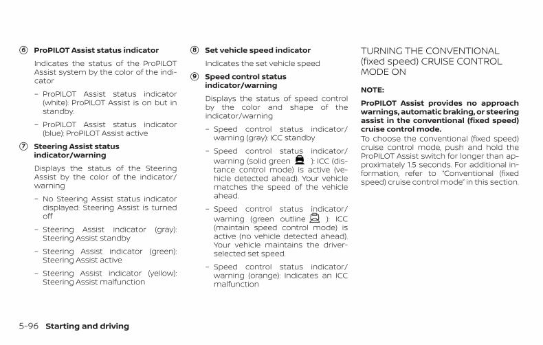
�6 ProPILOT Assist status indicator
Indicates the status of the ProPILOTAssist system by the color of the indi-cator
– ProPILOT Assist status indicator(white): ProPILOT Assist is on but instandby.
– ProPILOT Assist status indicator(blue): ProPILOT Assist active
�7 Steering Assist statusindicator/warning
Displays the status of the SteeringAssist by the color of the indicator/warning
– No Steering Assist status indicatordisplayed: Steering Assist is turnedoff
– Steering Assist indicator (gray):Steering Assist standby
– Steering Assist indicator (green):Steering Assist active
– Steering Assist indicator (yellow):Steering Assist malfunction
�8 Set vehicle speed indicator
Indicates the set vehicle speed
�9 Speed control statusindicator/warning
Displays the status of speed controlby the color and shape of theindicator/warning
– Speed control status indicator/warning (gray): ICC standby
– Speed control status indicator/warning (solid green ): ICC (dis-tance control mode) is active (ve-hicle detected ahead). Your vehiclematches the speed of the vehicleahead.
– Speed control status indicator/warning (green outline ): ICC(maintain speed control mode) isactive (no vehicle detected ahead).Your vehicle maintains the driver-selected set speed.
– Speed control status indicator/warning (orange): Indicates an ICCmalfunction
TURNING THE CONVENTIONAL(fixed speed) CRUISE CONTROLMODE ON
NOTE:
ProPILOT Assist provides no approachwarnings, automatic braking, or steeringassist in the conventional (fixed speed)cruise control mode.To choose the conventional (fixed speed)cruise control mode, push and hold theProPILOT Assist switch for longer than ap-proximately 1.5 seconds. For additional in-formation, refer to “Conventional (fixedspeed) cruise control mode” in this section.
5-96 Starting and driving
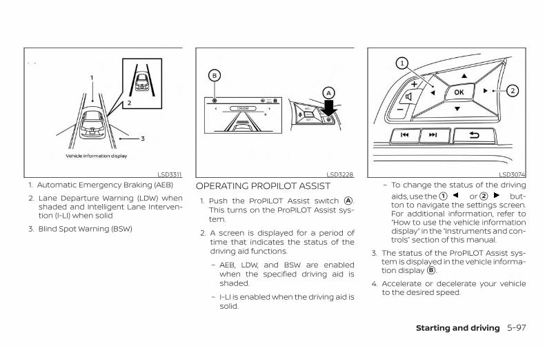
1. Automatic Emergency Braking (AEB)
2. Lane Departure Warning (LDW) whenshaded and Intelligent Lane Interven-tion (I-LI) when solid
3. Blind Spot Warning (BSW)
OPERATING PROPILOT ASSIST1. Push the ProPILOT Assist switch �A .
This turns on the ProPILOT Assist sys-tem.
2. A screen is displayed for a period oftime that indicates the status of thedriving aid functions.
– AEB, LDW, and BSW are enabledwhen the specified driving aid isshaded.
– I-LI is enabled when the driving aid issolid.
– To change the status of the drivingaids, use the �1 or �2 but-ton to navigate the settings screen.For additional information, refer to“How to use the vehicle informationdisplay” in the “Instruments and con-trols” section of this manual.
3. The status of the ProPILOT Assist sys-tem is displayed in the vehicle informa-tion display �B .
4. Accelerate or decelerate your vehicleto the desired speed.
LSD3311 LSD3228 LSD3074
Starting and driving 5-97
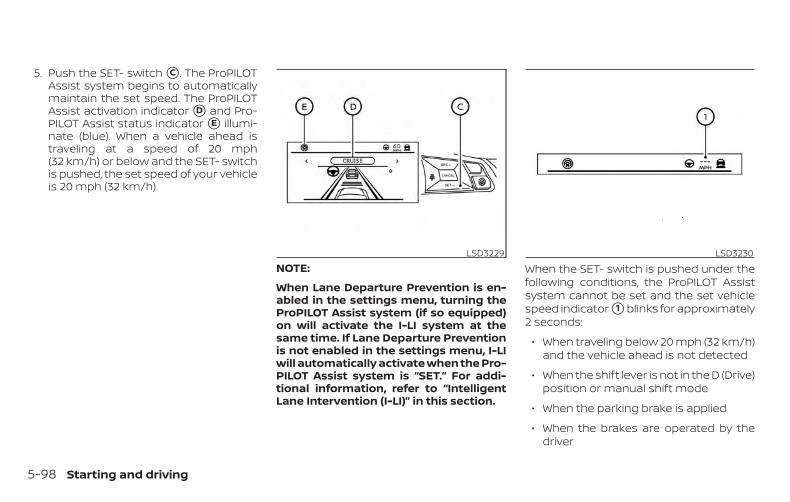
5. Push the SET- switch �C . The ProPILOTAssist system begins to automaticallymaintain the set speed. The ProPILOTAssist activation indicator �D and Pro-PILOT Assist status indicator �E illumi-nate (blue). When a vehicle ahead istraveling at a speed of 20 mph(32 km/h) or below and the SET- switchis pushed, the set speed of your vehicleis 20 mph (32 km/h).
NOTE:
When Lane Departure Prevention is en-abled in the settings menu, turning theProPILOT Assist system (if so equipped)on will activate the I-LI system at thesame time. If Lane Departure Preventionis not enabled in the settings menu, I-LIwill automatically activate when the Pro-PILOT Assist system is “SET.” For addi-tional information, refer to “IntelligentLane Intervention (I-LI)” in this section.
When the SET- switch is pushed under thefollowing conditions, the ProPILOT Assistsystem cannot be set and the set vehiclespeed indicator �1 blinks for approximately2 seconds:
∙ When traveling below 20 mph (32 km/h)and the vehicle ahead is not detected
∙ When the shift lever is not in the D (Drive)position or manual shift mode
∙ When the parking brake is applied
∙ When the brakes are operated by thedriver
LSD3229 LSD3230
5-98 Starting and driving
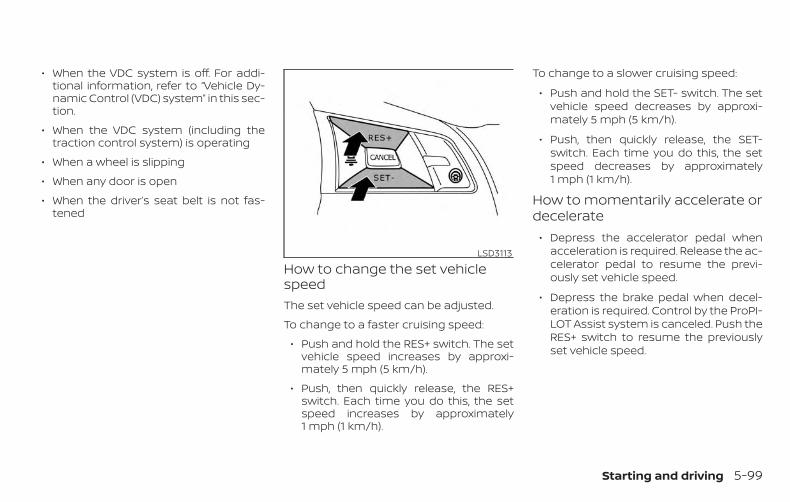
∙ When the VDC system is off. For addi-tional information, refer to “Vehicle Dy-namic Control (VDC) system” in this sec-tion.
∙ When the VDC system (including thetraction control system) is operating
∙ When a wheel is slipping
∙ When any door is open
∙ When the driver’s seat belt is not fas-tened
How to change the set vehiclespeedThe set vehicle speed can be adjusted.
To change to a faster cruising speed:
∙ Push and hold the RES+ switch. The setvehicle speed increases by approxi-mately 5 mph (5 km/h).
∙ Push, then quickly release, the RES+switch. Each time you do this, the setspeed increases by approximately1 mph (1 km/h).
To change to a slower cruising speed:
∙ Push and hold the SET- switch. The setvehicle speed decreases by approxi-mately 5 mph (5 km/h).
∙ Push, then quickly release, the SET-switch. Each time you do this, the setspeed decreases by approximately1 mph (1 km/h).
How to momentarily accelerate ordecelerate
∙ Depress the accelerator pedal whenacceleration is required. Release the ac-celerator pedal to resume the previ-ously set vehicle speed.
∙ Depress the brake pedal when decel-eration is required. Control by the ProPI-LOT Assist system is canceled. Push theRES+ switch to resume the previouslyset vehicle speed.
LSD3113
Starting and driving 5-99
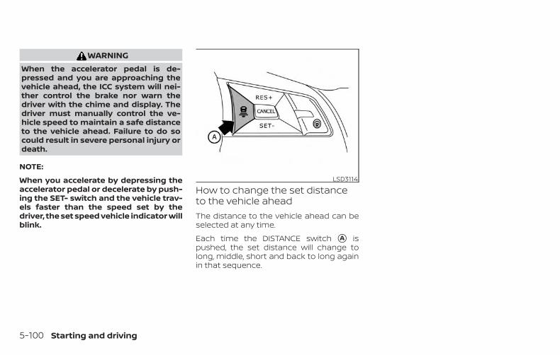
WARNINGWhen the accelerator pedal is de-pressed and you are approaching thevehicle ahead, the ICC system will nei-ther control the brake nor warn thedriver with the chime and display. Thedriver must manually control the ve-hicle speed to maintain a safe distanceto the vehicle ahead. Failure to do socould result in severe personal injury ordeath.
NOTE:
When you accelerate by depressing theaccelerator pedal or decelerate by push-ing the SET- switch and the vehicle trav-els faster than the speed set by thedriver, the set speed vehicle indicator willblink.
How to change the set distanceto the vehicle aheadThe distance to the vehicle ahead can beselected at any time.
Each time the DISTANCE switch �A ispushed, the set distance will change tolong, middle, short and back to long againin that sequence.
LSD3114
5-100 Starting and driving
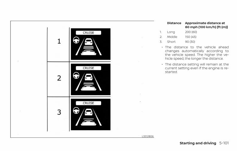
Distance Approximate distance at60 mph (100 km/h) [ft (m)]
1. Long 200 (60)2. Middle 150 (45)3. Short 90 (30)
∙ The distance to the vehicle aheadchanges automatically according tothe vehicle speed. The higher the ve-hicle speed, the longer the distance.
∙ The distance setting will remain at thecurrent setting even if the engine is re-started.
LSD2806
Starting and driving 5-101
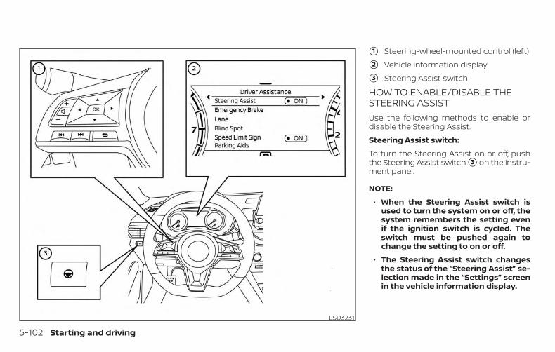
�1 Steering-wheel-mounted control (left)
�2 Vehicle information display
�3 Steering Assist switch
HOW TO ENABLE/DISABLE THESTEERING ASSISTUse the following methods to enable ordisable the Steering Assist.
Steering Assist switch:
To turn the Steering Assist on or off, pushthe Steering Assist switch �3 on the instru-ment panel.
NOTE:
∙ When the Steering Assist switch isused to turn the system on or off, thesystem remembers the setting evenif the ignition switch is cycled. Theswitch must be pushed again tochange the setting to on or off.
∙ The Steering Assist switch changesthe status of the “Steering Assist” se-lection made in the “Settings” screenin the vehicle information display.
LSD3231
5-102 Starting and driving
Setting in the vehicle information dis-play:
1. Press the button on the steeringwheel �1 until “Settings” displays in thevehicle information display �2 .
2. Use the button �1 to select“Driver Assistance.” Then press the OKbutton �1 .
3. Use the button �1 to select“Steering Assist” and then press the OKbutton �1 to turn the system on or off.
NOTE:
∙ When the Cruise screen is displayedon the vehicle information display,press the OK button on the steeringwheel to call up the “Driving Aids” set-ting display.
∙ When enabling/disabling the systemthrough the vehicle information dis-play or when pushing the SteeringAssist switch, the system retains thecurrent settings even if the engine isrestarted.
How to cancel the ProPILOT AssistsystemTo cancel the ProPILOT Assist system, useone of the following methods:
∙ Push the CANCEL switch.
∙ Tap the brake pedal (except at a stand-still).
∙ Push the ProPILOT Assist switch to turnthe system off. The ProPILOT Assist sta-tus indicator will go out.
When the ProPILOT Assist system is can-celed while the vehicle is stopped, the elec-tronic parking brake is automatically acti-vated.
WARNINGTo prevent the vehicle from moving orrolling unexpectedly, which could resultin serious personal injury or propertydamage, before exiting the vehiclemake sure to push the ProPILOT Assistswitch to turn the system off, place theshift lever in the P (Park) position, andturn the engine off.
INTELLIGENT CRUISE CONTROL(ICC) (for vehicles with ProPILOTAssist)
WARNINGFailure to follow the warnings and in-structions for proper use of the ICC sys-tem could result in serious injury ordeath.
∙ The ICC system is only an aid to assistthe driver and is not a collision warn-ing or avoidance device. It is recom-mended for highway use only and it isnot intended for city driving. It is thedriver’s responsibility to stay alert,drive safely, and be in control of thevehicle at all times.
∙ There are limitations to the ICC sys-tem capability. The ICC system doesnot function in all driving, traffic,weather, and road conditions. It is thedriver’s responsibility to stay alert,drive safely, keep the vehicle in thetraveling lane, and be in control of thevehicle at all times.
∙ Always observe posted speed limitsand do not set the speed over them.
Starting and driving 5-103
∙ The ICC system does not react to sta-tionary and slow moving vehicles.
∙ Always drive carefully and attentivelywhen using the ICC system. Read andunderstand the Owner’s Manual thor-oughly before using the ICC system.To avoid serious injury or death, donot rely on the system to prevent ac-cidents or to control the vehicle’sspeed in emergency situations. Donot use the ICC system except in ap-propriate road and traffic conditions.
ICC system operationThe ICC system is designed to maintain aselected distance from the vehicle in frontof you and can reduce the speed to matcha slower vehicle ahead. The system decel-erates the vehicle as necessary and if thevehicle ahead comes to a stop, the vehicledecelerates to a standstill. However, the ICCsystem can only apply up to 40% of thevehicle’s total braking power. This systemshould only be used when traffic condi-tions allow vehicle speeds to remain fairlyconstant or when vehicle speeds changegradually. If a vehicle moves into the travel-ing lane ahead or if a vehicle travelingahead rapidly decelerates, the distance be-tween vehicles may become closer be-
cause the ICC system cannot deceleratethe vehicle quickly enough. If this occurs,the ICC system sounds a warning chimeand blinks the system display to notify thedriver to take necessary action.
The ICC system cancels and a warningchime sounds if the speed is below ap-proximately 15 mph (24 km/h) and a vehicleis not detected ahead.
The ICC system operates as follows:
∙ When there are no vehicles travelingahead, the ICC system maintains thespeed set by the driver. The set speedrange is between approximately 20 and90 mph (32 and 144 km/h).
∙ When there is a vehicle traveling ahead,the ICC system adjusts the speed tomaintain the distance, selected by thedriver, from the vehicle ahead. If the ve-hicle ahead comes to a stop, the vehicledecelerates to a standstill. Once yourvehicle stops, the ICC system keeps thevehicle stopped.
∙ When your vehicle is stopped for lessthan 3 seconds and the vehicle aheadbegins to move, your vehicle will startmoving again automatically.
∙ When your vehicle is at a standstill formore than 3 seconds and the vehicleahead begins to accelerate, push theRES+ switch or lightly depress the accel-erator pedal. The ICC system starts tofollow the vehicle ahead.
∙ When the vehicle traveling aheadmoves to a different traveling lane, theICC system accelerates and maintainsvehicle speed up to the set speed.
The ICC system does not control vehiclespeed or warn you when you approachstationary and slow moving vehicles. Youmust pay attention to vehicle operation tomaintain proper distance from vehiclesahead when approaching toll gates or traf-fic congestion.
5-104 Starting and driving
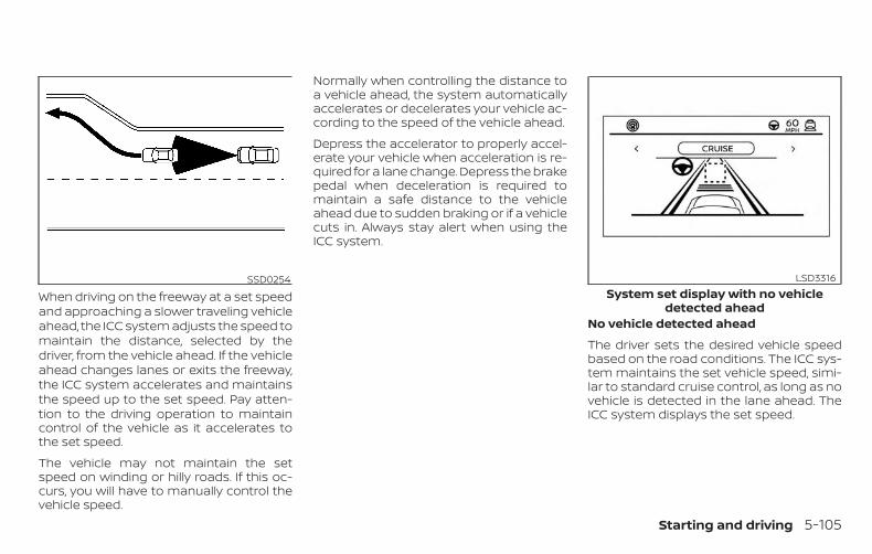
When driving on the freeway at a set speedand approaching a slower traveling vehicleahead, the ICC system adjusts the speed tomaintain the distance, selected by thedriver, from the vehicle ahead. If the vehicleahead changes lanes or exits the freeway,the ICC system accelerates and maintainsthe speed up to the set speed. Pay atten-tion to the driving operation to maintaincontrol of the vehicle as it accelerates tothe set speed.
The vehicle may not maintain the setspeed on winding or hilly roads. If this oc-curs, you will have to manually control thevehicle speed.
Normally when controlling the distance toa vehicle ahead, the system automaticallyaccelerates or decelerates your vehicle ac-cording to the speed of the vehicle ahead.
Depress the accelerator to properly accel-erate your vehicle when acceleration is re-quired for a lane change. Depress the brakepedal when deceleration is required tomaintain a safe distance to the vehicleahead due to sudden braking or if a vehiclecuts in. Always stay alert when using theICC system.
No vehicle detected ahead
The driver sets the desired vehicle speedbased on the road conditions. The ICC sys-tem maintains the set vehicle speed, simi-lar to standard cruise control, as long as novehicle is detected in the lane ahead. TheICC system displays the set speed.
SSD0254System set display with no vehicle
detected ahead
LSD3316
Starting and driving 5-105
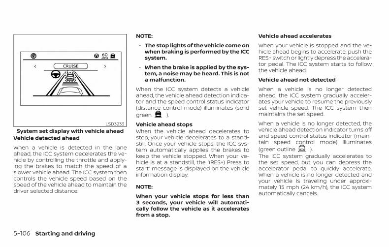
Vehicle detected ahead
When a vehicle is detected in the laneahead, the ICC system decelerates the ve-hicle by controlling the throttle and apply-ing the brakes to match the speed of aslower vehicle ahead. The ICC system thencontrols the vehicle speed based on thespeed of the vehicle ahead to maintain thedriver selected distance.
NOTE:
∙ The stop lights of the vehicle come onwhen braking is performed by the ICCsystem.
∙ When the brake is applied by the sys-tem, a noise may be heard. This is nota malfunction.
When the ICC system detects a vehicleahead, the vehicle ahead detection indica-tor and the speed control status indicator(distance control mode) illuminates (solidgreen ).
Vehicle ahead stopsWhen the vehicle ahead decelerates tostop, your vehicle decelerates to a stand-still. Once your vehicle stops, the ICC sys-tem automatically applies the brakes tokeep the vehicle stopped. When your ve-hicle is at a standstill, the “(RES+) Press tostart” message is displayed on the vehicleinformation display.
NOTE:
When your vehicle stops for less than3 seconds, your vehicle will automati-cally follow the vehicle as it acceleratesfrom a stop.
Vehicle ahead accelerates
When your vehicle is stopped and the ve-hicle ahead begins to accelerate, push theRES+ switch or lightly depress the accelera-tor pedal. The ICC system starts to followthe vehicle ahead.
Vehicle ahead not detected
When a vehicle is no longer detectedahead, the ICC system gradually acceler-ates your vehicle to resume the previouslyset vehicle speed. The ICC system thenmaintains the set speed.
When a vehicle is no longer detected, thevehicle ahead detection indicator turns offand speed control status indicator (main-tain speed control mode) illuminates(green outline ).The ICC system gradually accelerates tothe set speed, but you can depress theaccelerator pedal to quickly accelerate.When a vehicle is no longer detected andyour vehicle is traveling under approxi-mately 15 mph (24 km/h), the ICC systemautomatically cancels.
System set display with vehicle aheadLSD3233
5-106 Starting and driving
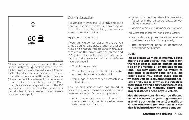
When passing another vehicle, the setspeed indicator �A flashes when the ve-hicle speed exceeds the set speed. The ve-hicle ahead detection indicator turns offwhen the area ahead of the vehicle is open.When the pedal is released, the vehicle re-turns to the previously set speed. Eventhough your vehicle speed is set in the ICCsystem, you can depress the acceleratorpedal when it is necessary to accelerateyour vehicle rapidly.
Cut-in detectionIf a vehicle moves into your traveling lanenear your vehicle, the ICC system may in-form the driver by flashing the vehicleahead detection indicator.
Approach warningIf your vehicle comes closer to the vehicleahead due to rapid deceleration of that ve-hicle or if another vehicle cuts in, the sys-tem warns the driver with the chime andICC system display. Decelerate by depress-ing the brake pedal to maintain a safe ve-hicle distance if:
∙ The chime sounds.
∙ The vehicle ahead detection indicatorand set distance indicator blink.
∙ You judge it necessary to maintain asafe distance.
The warning chime may not sound insome cases when there is a short distancebetween vehicles. Some examples are:
∙ When the vehicles are traveling at thesame speed and the distance betweenvehicles is not changing.
∙ When the vehicle ahead is travelingfaster and the distance between ve-hicles is increasing.
∙ When a vehicle cuts in near your vehicle.
The warning chime will not sound when:
∙ Your vehicle approaches other vehiclesthat are parked or moving slowly.
∙ The accelerator pedal is depressed,overriding the system.
NOTE:The approach warning chime may soundand the system display may flash whenthe radar sensor detects objects on theside of the vehicle or on the side of theroad. This may cause the ICC system todecelerate or accelerate the vehicle. Theradar sensor may detect these objectswhen the vehicle is driven on winding, nar-row, or hilly roads or when the vehicle isentering or exiting a curve. In these cases,you will have to manually control theproper distance ahead of your vehicle.
Also, the sensor sensitivity can be affectedby vehicle operation (steering maneuveror driving position in the lane) or traffic orvehicle conditions (for example, if a ve-hicle is being driven with some damage).
LSD3234
Starting and driving 5-107
Acceleration when passingWhen the ICC system is engaged above37 mph and following a slower vehicle (be-low ICC set speed), and the turn signal isactivated to the left, the ICC system willautomatically start to accelerate the ve-hicle to help initiate passing on the left andwill begin to reduce the distance to vehicledirectly ahead. Only the left side turn signaloperates this feature. As the driver steersthe vehicle and moves into the passinglane, if no vehicle is detected ahead the ICCsystem will continue to accelerate to theICC system set speed. If another vehicle isdetected ahead, then the vehicle will accel-erate up to the following speed of that ve-hicle. If the vehicle is not steered into theleft lane to pass, the acceleration will stopafter a short time and regain the set follow-ing distance. Acceleration can be stoppedat any point by depressing the brake pedalor the CANCEL switch on the steeringwheel.
WARNINGIn order to reduce the risk of a collisionthat may result in serious injury ordeath, please be aware of the following:
∙ This function is only activated withthe left turn signal and will briefly ac-celerate the vehicle even if a lanechange is not initiated. This can in-clude non-passing situations such asleft side exits.
∙ Ensure that when passing another ve-hicle, the adjacent lane is clear beforeinitiating the pass. Sudden changesin traffic may occur while passing -always manually steer or brake asneeded- never solely rely on thesystem.
ICC system limitations
WARNINGListed below are the system limitationsfor the ICC system. Failure to operatethe vehicle in accordance with thesesystem limitations could result in seri-ous injury or death:∙ The ICC system is primarily intended
for use on straight, dry, open roadswith light traffic. It is not advisable touse the ICC system in city traffic orcongested areas.
∙ The ICC system will not adapt auto-matically to road conditions. This sys-tem should be used in evenly flowingtraffic. Do not use the system on roadswith sharp curves or on icy roads, inheavy rain or in fog.
5-108 Starting and driving
∙ As there is a performance limit to thedistance control function, never relysolely on the ICC system. This systemdoes not correct careless, inattentiveor absentminded driving or overcomepoor visibility in rain, fog, or other badweather. Decelerate the vehicle speedby depressing the brake pedal, de-pending on the distance to the vehicleahead and the surrounding circum-stances in order to maintain a safedistance between vehicles.
∙ When the ICC system automaticallybrings the car to a stop, your vehiclecan automatically accelerate if the ve-hicle is stopped for less than approxi-mately 3 seconds. Be prepared to stopyour vehicle if necessary.
∙ Always pay attention to the operationof the vehicle and be ready to manu-ally control the proper following dis-tance. The ICC system may not be ableto maintain the selected distance be-tween vehicles (following distance) orselected vehicle speed under somecircumstances.
∙ The system may not detect the ve-hicle in front of you in certain road orweather conditions. To avoid acci-dents, never use the ICC system underthe following conditions:
– On roads with heavy, high-speedtraffic or sharp curves
– On slippery road surfaces such ason ice or snow, etc.
– During bad weather (rain, fog,snow, etc.)
– When rain, snow or dirt adhere tothe bumper around the distancesensor
– On steep downhill roads (the vehiclemay go beyond the set vehiclespeed and frequent braking may re-sult in overheating the brakes)
– On repeated uphill and downhillroads
– When traffic conditions make it dif-ficult to keep a proper distance be-tween vehicles because of fre-quent acceleration or deceleration
– Interference by other radar sources.
∙ Do not use the ICC system if you aretowing a trailer. The system may notdetect a vehicle ahead.
∙ In some road or traffic conditions, avehicle or object can unexpectedlycome into the sensor detection zoneand cause automatic braking. Alwaysstay alert and avoid using the ICC sys-tem where not recommended in thiswarning section.
The ICC system will not detect the followingobjects:
∙ Stationary or slow moving vehicles
∙ Pedestrians or objects in the roadway
∙ Oncoming vehicles in the same lane
∙ Motorcycles traveling offset in the travellane
Starting and driving 5-109
The following are some conditions in whichthe radar sensor cannot properly detect avehicle ahead and the system may not op-erate properly:
∙ When the sensor detection is reduced(conditions such as rain, snow, fog, duststorms, sandstorms, and road sprayfrom other vehicles)
∙ Driving on a steep downhill slope orroads with sharp curves
∙ Driving on a bumpy road surface, suchas an uneven dirt road
∙ If dirt, ice, snow or other material is cov-ering the radar sensor area
∙ A complicated-shaped vehicle such asa car carrier trailer or flatbed truck/trailer is near the vehicle ahead.
∙ Interference by other radar sources
∙ When your vehicle is towing a trailer, etc.
∙ When excessively heavy baggage isloaded in the rear seat or cargo area ofyour vehicle.
The ICC system is designed to automati-cally check the radar sensor’s operationwithin the limitations of the system.
The detection zone of the radar sensor islimited. A vehicle ahead must be in the de-tection zone for the ICC system to maintainthe selected distance from the vehicleahead. A vehicle ahead may move outsideof the detection zone due to its positionwithin the same lane of travel. Motorcyclesmay not be detected in the same laneahead if they are traveling offset from thecenter line of the lane. A vehicle that is en-tering the lane ahead may not be detecteduntil the vehicle has completely moved intothe lane.
If this occurs, the ICC system may warn youby blinking the system indicator andsounding the chime. The driver may haveto manually control the proper distanceaway from the vehicle traveling ahead.
The ICC system (with ProPILOT Assist) usesa multi-sensing front camera. The follow-ing are some conditions in which the cam-era may not properly detect a vehicle anddetection of a vehicle ahead may be de-layed:
∙ Poor visibility (conditions such as rain,snow, fog, dust storms, sandstorms,and road spray from other vehicles)
∙ The camera area of the windshield isfogged up or covered with dirt, waterdrops, ice, snow, etc.
∙ Strong light (for example, sunlight orhigh beams from oncoming vehicles)enters the front camera
∙ A sudden change in brightness occurs(for example, when the vehicle enters orexits a tunnel or shaded area or light-ning flashes)
5-110 Starting and driving

SSD0252
Starting and driving 5-111
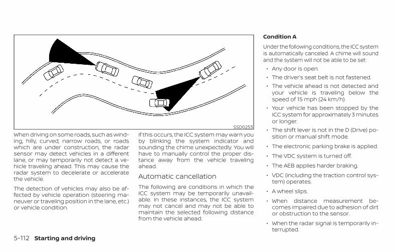
When driving on some roads, such as wind-ing, hilly, curved, narrow roads, or roadswhich are under construction, the radarsensor may detect vehicles in a differentlane, or may temporarily not detect a ve-hicle traveling ahead. This may cause theradar system to decelerate or acceleratethe vehicle.
The detection of vehicles may also be af-fected by vehicle operation (steering ma-neuver or traveling position in the lane, etc.)or vehicle condition.
If this occurs, the ICC system may warn youby blinking the system indicator andsounding the chime unexpectedly. You willhave to manually control the proper dis-tance away from the vehicle travelingahead.
Automatic cancellationThe following are conditions in which theICC system may be temporarily unavail-able. In these instances, the ICC systemmay not cancel and may not be able tomaintain the selected following distancefrom the vehicle ahead.
Condition A
Under the following conditions, the ICC systemis automatically canceled. A chime will soundand the system will not be able to be set:
∙ Any door is open.∙ The driver’s seat belt is not fastened.∙ The vehicle ahead is not detected and
your vehicle is traveling below thespeed of 15 mph (24 km/h).
∙ Your vehicle has been stopped by theICC system for approximately 3 minutesor longer.
∙ The shift lever is not in the D (Drive) po-sition or manual shift mode.
∙ The electronic parking brake is applied.
∙ The VDC system is turned off.
∙ The AEB applies harder braking.
∙ VDC (including the traction control sys-tem) operates.
∙ A wheel slips.
∙ When distance measurement be-comes impaired due to adhesion of dirtor obstruction to the sensor.
∙ When the radar signal is temporarily in-terrupted.
SSD0253
5-112 Starting and driving
Action to take:
When the conditions listed above are nolonger present, turn the system off usingthe ProPILOT Assist switch. Turn the Pro-PILOT Assist system back on to use thesystem.
NOTE:
When the ICC system is canceled underthe following conditions at a standstill,the electronic parking brake is auto-matically activated:
∙ Any door is open.
∙ The driver’s seat belt is not fastened.
∙ Your vehicle has been stopped by theICC system for approximately 3 min-utes or longer.
∙ The shift lever is not in the D (Drive)position or manual shift mode.
∙ The VDC system is turned off.
∙ When distance measurement be-comes impaired due to adhesion ofdirt or obstruction to the sensor.
∙ When the radar signal is temporarilyinterrupted.
Condition B
When the radar sensor of the front bumperis covered with dirt or is obstructed, the ICCsystem will automatically be canceled.
The chime will sound and the “Not Avail-able: Front Radar Blocked” warning mes-sage will appear in the vehicle informationdisplay.
Action to take:
If the warning message appears, stop thevehicle in a safe place, place the shift leverin the P (Park) position, and turn the engineoff. When the radar signal is temporarilyinterrupted, clean the sensor area of thefront bumper and restart the engine. If the“Not Available: Front Radar Blocked” warn-ing message continues to be displayed,have the system checked. It is recom-mended that you visit a NISSAN dealer forthis service.
Condition C
When driving on roads with limited roadstructures or buildings (for example, longbridges, deserts, snow fields, driving next tolong walls), the system may illuminate thesystem warning light and display the “NotAvailable: Front Radar Blocked” message.
Action to take:
When the above driving conditions no lon-ger exist, turn the system back on.
ICC system malfunctionIf the ICC system malfunctions, it will beturned off automatically, a chime willsound, and the speed control status warn-ing (orange) will illuminate.
Action to take:
If the warning light comes on, stop the ve-hicle in a safe place. Turn the engine off,restart the engine and set the ICC systemagain. If it is not possible to set the ICCsystem or the indicator stays on, it may bea malfunction. Although the normal drivingcan be continued, the ICC system shouldbe inspected. It is recommended that youvisit a NISSAN dealer for this service.
ICC sensor maintenanceThe radar sensor is located on the front ofthe vehicle.
Starting and driving 5-113
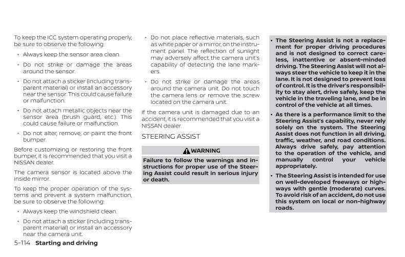
To keep the ICC system operating properly,be sure to observe the following:
∙ Always keep the sensor area clean.
∙ Do not strike or damage the areasaround the sensor.
∙ Do not attach a sticker (including trans-parent material) or install an accessorynear the sensor. This could cause failureor malfunction.
∙ Do not attach metallic objects near thesensor area (brush guard, etc.). Thiscould cause failure or malfunction.
∙ Do not alter, remove, or paint the frontbumper.
Before customizing or restoring the frontbumper, it is recommended that you visit aNISSAN dealer.
The camera sensor is located above theinside mirror.
To keep the proper operation of the sys-tems and prevent a system malfunction,be sure to observe the following:
∙ Always keep the windshield clean.
∙ Do not attach a sticker (including trans-parent material) or install an accessorynear the camera unit.
∙ Do not place reflective materials, suchas white paper or a mirror, on the instru-ment panel. The reflection of sunlightmay adversely affect the camera unit’scapability of detecting the lane mark-ers.
∙ Do not strike or damage the areasaround the camera unit. Do not touchthe camera lens or remove the screwlocated on the camera unit.
If the camera unit is damaged due to anaccident, it is recommended that you visit aNISSAN dealer.
STEERING ASSIST
WARNINGFailure to follow the warnings and in-structions for proper use of the Steer-ing Assist could result in serious injuryor death.
∙ The Steering Assist is not a replace-ment for proper driving proceduresand is not designed to correct care-less, inattentive or absent-mindeddriving. The Steering Assist will not al-ways steer the vehicle to keep it in thelane. It is not designed to prevent lossof control. It is the driver’s responsibil-ity to stay alert, drive safely, keep thevehicle in the traveling lane, and be incontrol of the vehicle at all times.
∙ As there is a performance limit to theSteering Assist’s capability, never relysolely on the system. The SteeringAssist does not function in all driving,traffic, weather, and road conditions.Always drive safely, pay attentionto the operation of the vehicle, andmanually control your vehicleappropriately.
∙ The Steering Assist is intended for useon well-developed freeways or high-ways with gentle (moderate) curves.To avoid risk of an accident, do not usethis system on local or non-highwayroads.
5-114 Starting and driving
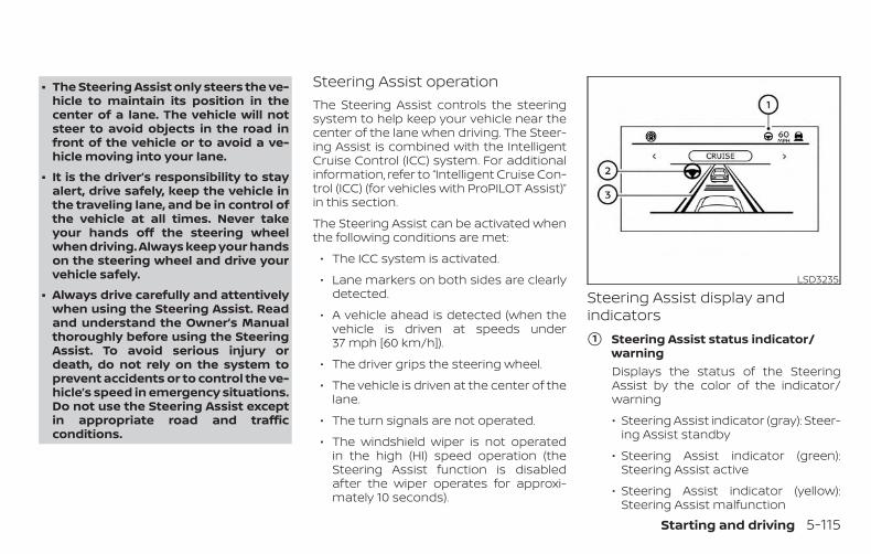
∙ The Steering Assist only steers the ve-hicle to maintain its position in thecenter of a lane. The vehicle will notsteer to avoid objects in the road infront of the vehicle or to avoid a ve-hicle moving into your lane.
∙ It is the driver’s responsibility to stayalert, drive safely, keep the vehicle inthe traveling lane, and be in control ofthe vehicle at all times. Never takeyour hands off the steering wheelwhen driving. Always keep your handson the steering wheel and drive yourvehicle safely.
∙ Always drive carefully and attentivelywhen using the Steering Assist. Readand understand the Owner’s Manualthoroughly before using the SteeringAssist. To avoid serious injury ordeath, do not rely on the system toprevent accidents or to control the ve-hicle’s speed in emergency situations.Do not use the Steering Assist exceptin appropriate road and trafficconditions.
Steering Assist operationThe Steering Assist controls the steeringsystem to help keep your vehicle near thecenter of the lane when driving. The Steer-ing Assist is combined with the IntelligentCruise Control (ICC) system. For additionalinformation, refer to “Intelligent Cruise Con-trol (ICC) (for vehicles with ProPILOT Assist)”in this section.
The Steering Assist can be activated whenthe following conditions are met:
∙ The ICC system is activated.
∙ Lane markers on both sides are clearlydetected.
∙ A vehicle ahead is detected (when thevehicle is driven at speeds under37 mph [60 km/h]).
∙ The driver grips the steering wheel.
∙ The vehicle is driven at the center of thelane.
∙ The turn signals are not operated.
∙ The windshield wiper is not operatedin the high (HI) speed operation (theSteering Assist function is disabledafter the wiper operates for approxi-mately 10 seconds).
Steering Assist display andindicators
�1 Steering Assist status indicator/warningDisplays the status of the SteeringAssist by the color of the indicator/warning
∙ Steering Assist indicator (gray): Steer-ing Assist standby
∙ Steering Assist indicator (green):Steering Assist active
∙ Steering Assist indicator (yellow):Steering Assist malfunction
LSD3235
Starting and driving 5-115
�2 Steering Assist indicator
Indicates the status of the Steering As-sist by the color of the indicator
∙ Steering Assist indicator (gray): Steer-ing Assist standby
∙ Steering Assist indicator (green):Steering Assist active
�3 Lane marker indicator
Indicates whether the system detectsthe lane marker
∙ Lane marker indicator (gray): Lanemarkers not detected
∙ Lane marker indicator (green): Lanemarkers detected
∙ Lane marker indicator (yellow): Lanedeparture is detected
When the Steering Assist is in operation,the Steering Assist status indicator �1 , theSteering Assist indicator �2 , and the lanemarker indicator �3 on the vehicle infor-mation display turn green. A chime soundswhen the Steering Assist initially activates.
When the Steering Assist deactivates, theSteering Assist status indicator �1 , theSteering Assist indicator �2 , and the lanemarker indicator �3 on the vehicle infor-mation display turn gray and a chimesounds twice.
Intelligent Lane Intervention (I-LI)When a curve or strong cross wind exceedsthe capabilities of the Steering Assist andyour vehicle approaches either the left orthe right side of the traveling lane, the I-LIindicator (orange) on the instrument panelflashes to alert the driver. Then, the I-LI sys-tem automatically applies the brakes for ashort period of time to help assist thedriver to return the vehicle to the center ofthe traveling lane. This action is in additionto any Steering Assist actions.
5-116 Starting and driving
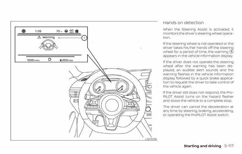
Hands on detectionWhen the Steering Assist is activated, itmonitors the driver’s steering wheel opera-tion.
If the steering wheel is not operated or thedriver takes his/her hands off the steeringwheel for a period of time, the warning �1appears in the vehicle information display.
If the driver does not operate the steeringwheel after the warning has been dis-played, an audible alert sounds and thewarning flashes in the vehicle informationdisplay, followed by a quick brake applica-tion to request the driver to take control ofthe vehicle again.
If the driver still does not respond, the Pro-PILOT Assist turns on the hazard flasherand slows the vehicle to a complete stop.
The driver can cancel the deceleration atany time by steering, braking, accelerating,or operating the ProPILOT Assist switch.
LSD3236
Starting and driving 5-117
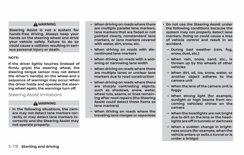
WARNINGSteering Assist is not a system forhands-free driving. Always keep yourhands on the steering wheel and driveyour vehicle safely. Failure to do socould cause a collision resulting in seri-ous personal injury or death.
NOTE:
If the driver lightly touches (instead offirmly grips) the steering wheel, thesteering torque sensor may not detectthe driver’s hand(s) on the wheel and asequence of warnings may occur. Whenthe driver holds and operates the steer-ing wheel again, the warnings turn off.
Steering Assist limitations
WARNING∙ In the following situations, the cam-
era may not detect lane markers cor-rectly or may detect lane markers in-correctly and the Steering Assist maynot operate properly:
– When driving on roads where thereare multiple parallel lane markers,lane markers that are faded or notpainted clearly, nonstandard lanemarkers, or lane markers coveredwith water, dirt, snow, etc.
– When driving on roads with dis-continued lane markers
– When driving on roads with a wid-ening or narrowing lane width
– When driving on roads where thereare multiple lanes or unclear lanemarkers due to road construction
– When driving on roads where thereare sharply contrasting objects,such as shadows, snow, water,wheel ruts, seams, or lines remain-ing after road repairs (the SteeringAssist could detect these items aslane markers)
– When driving on roads where thetraveling lane merges or separates
∙ Do not use the Steering Assist underthe following conditions because thesystem may not properly detect lanemarkers. Doing so could cause a lossof vehicle control and result in anaccident.
– During bad weather (rain, fog,snow, dust, etc.)
– When rain, snow, sand, etc., isthrown up by the wheels of othervehicles
– When dirt, oil, ice, snow, water, oranother object adheres to thecamera unit
– When the lens of the camera unit isfoggy
– When strong light (for example,sunlight or high beams from on-coming vehicles) shines on thecamera
– When the headlights are not brightdue to dirt on the lens or the head-lights are off in tunnels or darkness
– When a sudden change in bright-ness occurs (for example, when thevehicle enters or exits a tunnel or isunder a bridge)
5-118 Starting and driving
– When driving on roads where thetraveling lane merges or separatesor where there are temporary lanemarkers because of roadconstruction
– When there is a lane closure due toroad repairs
– When driving on a bumpy road sur-face, such as an uneven dirt road
– When driving on sharp curves orwinding roads
– When driving on repeated uphilland downhill roads
∙ Do not use the Steering Assist underthe following conditions because thesystem will not operate properly:
– When driving with a tire that is notwithin normal tire conditions (forexample, tire wear, abnormal tirepressure, installation of a sparetire, tire chains, nonstandardwheels)
– When the vehicle is equipped withnon-original brake or suspensionparts
– When an object such as a sticker orcargo obstructs the camera
– When excessively heavy baggageis loaded in the rear seat or lug-gage area of your vehicle
– When the vehicle load capacity isexceeded
– When towing a trailer or othervehicle
∙ Excessive noise will interfere with thewarning chime sound, and the beepmay not be heard.
∙ For the ProPILOT Assist system to op-erate properly, the windshield in frontof the camera must be clean. Replaceworn wiper blades. The correct sizewiper blades must be used to helpmake sure the windshield is keptclean. Only use Genuine NISSAN wiperblades, or equivalent wiper blades,that are specifically designed for useon your vehicle model and modelyear. It is recommended that you visita NISSAN dealer for the correct partsfor your vehicle.
Steering Assist temporarystandbyAutomatic standby due to driving opera-tion:
When the driver activates the turn signal,the Steering Assist is temporarily placed ina standby mode. (The Steering Assist re-starts automatically when the operatingconditions are met again.)
Automatic standby:
In the following cases, a warning messageis displayed along with the chime, and theSteering Assist is placed in a temporarystandby mode. (The Steering Assist re-starts automatically when the operatingconditions are met again.)
∙ When lane markers on both sides areno longer detected
∙ When a vehicle ahead is no longer de-tected under approximately 37 mph(60 km/h)
Starting and driving 5-119
Steering Assist cancelUnder the following conditions, the Steer-ing Assist cancels, and the Steering Assiststatus indicator and the Steering Assist in-dicator turn off:
∙ When unusual lane markers appear inthe traveling lane or when the lanemarker cannot be correctly detectedfor some time due to certain conditions(for example, a snow rut, the reflectionof light on a rainy day, the presence ofseveral unclear lane markers)
∙ When the windshield wiper operates inthe high (HI) speed operation (the Steer-ing Assist is disabled when the wiperoperates for more than approximately10 seconds)
Action to take:
Turn the ICC system off using the CANCELswitch. When the conditions listed aboveare no longer present, turn the ICC systemon again.
Steering Assist malfunctionWhen the system malfunctions, it turns offautomatically. The Steering Assist statuswarning illuminates (orange). A chime maysound depending on the situation.
Action to take:
Stop the vehicle in a safe location, place thevehicle in the P (Park) position, turn the en-gine off, restart the engine, resume driving,and set the Intelligent Cruise Control sys-tem again. If the warning (orange) contin-ues to illuminate, the Steering Assist is mal-functioning. Although the vehicle is stilldrivable under normal conditions, have thesystem checked. It is recommended thatyou visit a NISSAN dealer for this service.
Steering Assist maintenanceThe camera sensor is located above theinside mirror.
To keep the proper operation of the systemand prevent a system malfunction, be sureto observe the following:
∙ Always keep the windshield clean.
∙ Do not attach a sticker (including trans-parent material) or install an accessorynear the camera unit.
∙ Do not place reflective materials, suchas white paper or a mirror, on the instru-ment panel. The reflection of sunlightmay adversely affect the camera unit’scapability of detecting the lane mark-ers.
∙ Do not strike or damage the areasaround the camera unit. Do not touchthe camera lens or remove the screwlocated on the camera unit.
If the camera unit is damaged due to anaccident, it is recommended that you visit aNISSAN dealer.
Radio frequency statement
For USA
FCC ID OAYARS4B
This device complies with Part 15 of the FCCRules. Operation is subject to the followingtwo conditions:
1. This device may not cause harmful in-terference, and
2. This device must accept any interfer-ence received, including interferencethat may cause undesired operation.
FCC Warning
Changes or modifications not expresslyapproved by the party responsible forcompliance could void the user’s authorityto operate the equipment.
5-120 Starting and driving
For Canada
Model: ARS4–B
IC: 4135A-ARS4B
FCC ID: OAYARS4B
This device complies with Part 15 of the FCCRules and with Industry Canada licence-exempt RSS standard(s). Operation is sub-ject to the following two conditions:
1. This device may not cause harmful in-terference, and
2. This device must accept any interfer-ence received, including interferencethat may cause undesired operation.
Le present appareil est conforme aux CNRd’Industrie Canada applicables aux appar-eils radio exempts de licence. L’exploitationest autorisee aux deux conditions suiv-antes:
1. L’appareil ne doit pas produire debrouillage, et
2. L’utilisateur de l’appareil doit acceptertout brouillage radioelectrique subi,meme si le brouillage est susceptibled’en compromettre le fonctionnement.
Radio Frequency Radiation Exposure Infor-mation:
This equipment complies with FCC radia-tion exposure limits set forth for an uncon-trolled environment.
This equipment should be installed andoperated with minimum distance of 30 cmbetween the radiator and your body.
The transmitter must not be co-located oroperating in conjunction with any other an-tenna or transmitter.
Cet equipement est conforme aux limitesd’exposition aux rayonnements IC etabliespour un environnement non controle. Cetequipement doit etre installe et utilise avecun minimum de 30 cm de distance entre lasource de rayonnement et votre corps.
FCC Notice
Changes or modifications not expresslyapproved by the party responsible forcompliance could void the user’s authorityto operate the equipment.
CONVENTIONAL (fixed speed)CRUISE CONTROL MODE
NOTE:
ProPILOT Assist provides no approachwarnings, automatic braking, or steeringassist in the conventional (fixed speed)cruise control mode.
This mode allows driving at a speed be-tween 25 to 90 mph (40 to 144 km/h) with-out keeping your foot on the acceleratorpedal.
WARNING∙ In the conventional (fixed speed)
cruise control mode, a warning chimedoes not sound to warn you if you aretoo close to the vehicle ahead, as nei-ther the presence of the vehicle aheadnor the vehicle-to-vehicle distance isdetected.
∙ Pay special attention to the distancebetween your vehicle and the vehicleahead of you or a collision could occur.
∙ Always confirm the setting in the ICCsystem display.
Starting and driving 5-121
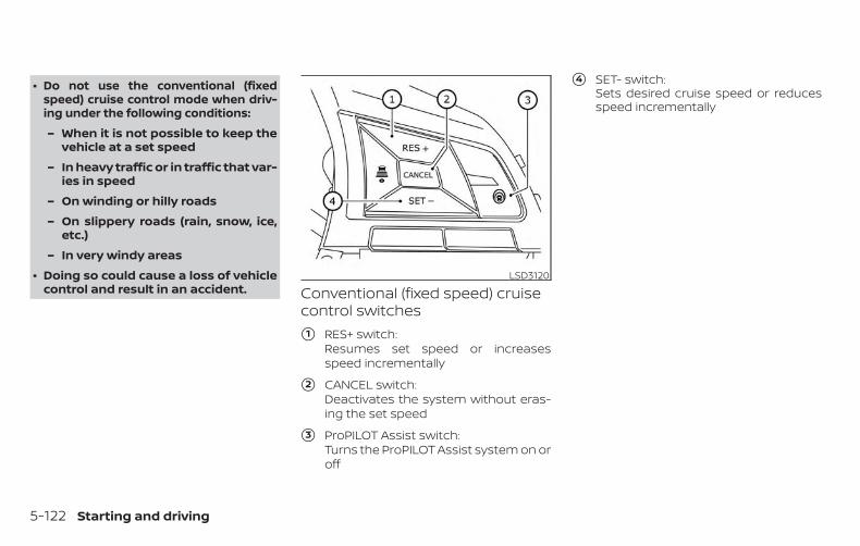
∙ Do not use the conventional (fixedspeed) cruise control mode when driv-ing under the following conditions:
– When it is not possible to keep thevehicle at a set speed
– In heavy traffic or in traffic that var-ies in speed
– On winding or hilly roads
– On slippery roads (rain, snow, ice,etc.)
– In very windy areas
∙ Doing so could cause a loss of vehiclecontrol and result in an accident. Conventional (fixed speed) cruise
control switches
�1 RES+ switch:Resumes set speed or increasesspeed incrementally
�2 CANCEL switch:Deactivates the system without eras-ing the set speed
�3 ProPILOT Assist switch:Turns the ProPILOT Assist system on oroff
�4 SET- switch:Sets desired cruise speed or reducesspeed incrementally
LSD3120
5-122 Starting and driving
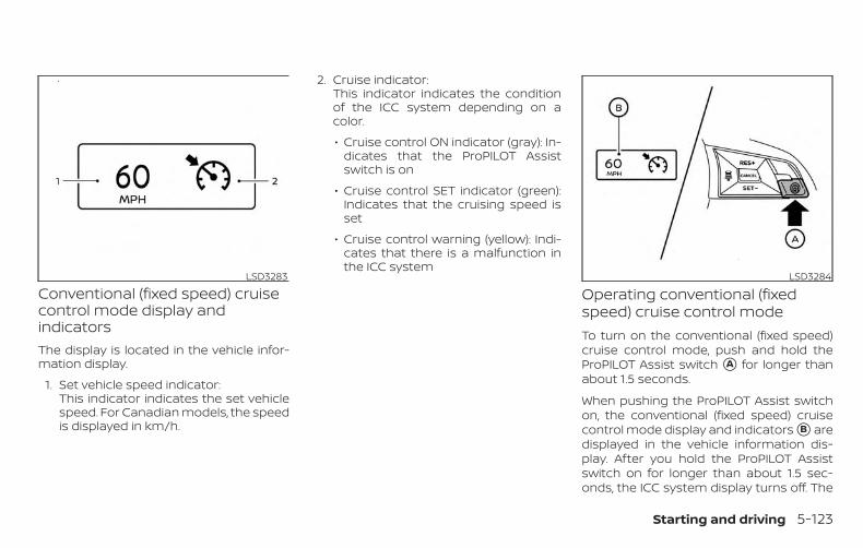
Conventional (fixed speed) cruisecontrol mode display andindicatorsThe display is located in the vehicle infor-mation display.
1. Set vehicle speed indicator:This indicator indicates the set vehiclespeed. For Canadian models, the speedis displayed in km/h.
2. Cruise indicator:This indicator indicates the conditionof the ICC system depending on acolor.
∙ Cruise control ON indicator (gray): In-dicates that the ProPILOT Assistswitch is on
∙ Cruise control SET indicator (green):Indicates that the cruising speed isset
∙ Cruise control warning (yellow): Indi-cates that there is a malfunction inthe ICC system
Operating conventional (fixedspeed) cruise control modeTo turn on the conventional (fixed speed)cruise control mode, push and hold theProPILOT Assist switch �A for longer thanabout 1.5 seconds.
When pushing the ProPILOT Assist switchon, the conventional (fixed speed) cruisecontrol mode display and indicators �B aredisplayed in the vehicle information dis-play. After you hold the ProPILOT Assistswitch on for longer than about 1.5 sec-onds, the ICC system display turns off. The
LSD3283 LSD3284
Starting and driving 5-123
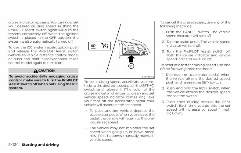
cruise indicator appears. You can now setyour desired cruising speed. Pushing theProPILOT Assist switch again will turn thesystem completely off. When the ignitionswitch is placed in the OFF position, thesystem is also automatically turned off.
To use the ICC system again, quickly pushand release the ProPILOT Assist switch(vehicle-to vehicle distance control mode)or push and hold it (conventional cruisecontrol mode) again to turn it on.
CAUTIONTo avoid accidentally engaging cruisecontrol, make sure to turn the ProPILOTAssist switch off when not using the ICCsystem.
To set cruising speed, accelerate your ve-hicle to the desired speed, push the SET- �Cswitch and release it. (The color of thecruise indicator changes to green and setvehicle speed indicator comes on.) Takeyour foot off the accelerator pedal. Yourvehicle will maintain the set speed.
∙ To pass another vehicle, depress theaccelerator pedal. When you release thepedal, the vehicle will return to the pre-viously set speed.
∙ The vehicle may not maintain the setspeed when going up or down steephills. If this happens, manually maintainvehicle speed.
To cancel the preset speed, use any of thefollowing methods:
1. Push the CANCEL switch. The vehiclespeed indicator will turn off.
2. Tap the brake pedal. The vehicle speedindicator will turn off.
3. Turn the ProPILOT Assist switch off.Both the cruise indicator and vehiclespeed indicator will turn off.
To reset at a faster cruising speed, use oneof the following three methods:
1. Depress the accelerator pedal. Whenthe vehicle attains the desired speed,push and release the SET- switch.
2. Push and hold the RES+ switch. Whenthe vehicle attains the desired speed,release the switch.
3. Push, then quickly release the RES+switch. Each time you do this, the setspeed will increase by about 1 mph(1.6 km/h).
LSD3285
5-124 Starting and driving
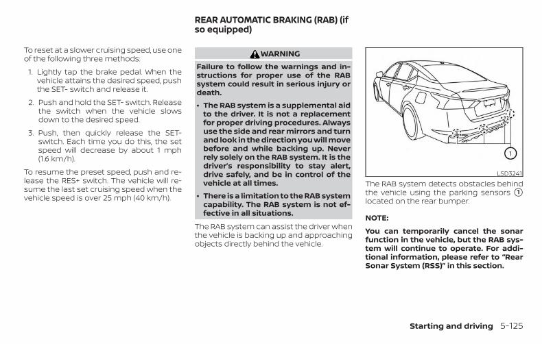
To reset at a slower cruising speed, use oneof the following three methods:
1. Lightly tap the brake pedal. When thevehicle attains the desired speed, pushthe SET- switch and release it.
2. Push and hold the SET- switch. Releasethe switch when the vehicle slowsdown to the desired speed.
3. Push, then quickly release the SET-switch. Each time you do this, the setspeed will decrease by about 1 mph(1.6 km/h).
To resume the preset speed, push and re-lease the RES+ switch. The vehicle will re-sume the last set cruising speed when thevehicle speed is over 25 mph (40 km/h).
WARNINGFailure to follow the warnings and in-structions for proper use of the RABsystem could result in serious injury ordeath.
∙ The RAB system is a supplemental aidto the driver. It is not a replacementfor proper driving procedures. Alwaysuse the side and rear mirrors and turnand look in the direction you will movebefore and while backing up. Neverrely solely on the RAB system. It is thedriver’s responsibility to stay alert,drive safely, and be in control of thevehicle at all times.
∙ There is a limitation to the RAB systemcapability. The RAB system is not ef-fective in all situations.
The RAB system can assist the driver whenthe vehicle is backing up and approachingobjects directly behind the vehicle.
The RAB system detects obstacles behindthe vehicle using the parking sensors �1located on the rear bumper.
NOTE:
You can temporarily cancel the sonarfunction in the vehicle, but the RAB sys-tem will continue to operate. For addi-tional information, please refer to “RearSonar System (RSS)” in this section.
LSD3241
REAR AUTOMATIC BRAKING (RAB) (ifso equipped)
Starting and driving 5-125
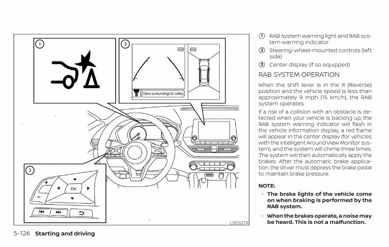
�1 RAB system warning light and RAB sys-tem warning indicator
�2 Steering-wheel-mounted controls (leftside)
�3 Center display (if so equipped)
RAB SYSTEM OPERATIONWhen the shift lever is in the R (Reverse)position and the vehicle speed is less thanapproximately 9 mph (15 km/h), the RABsystem operates.If a risk of a collision with an obstacle is de-tected when your vehicle is backing up, theRAB system warning indicator will flash inthe vehicle information display, a red framewill appear in the center display (for vehicleswith the Intelligent Around View Monitor sys-tem), and the system will chime three times.The system will then automatically apply thebrakes. After the automatic brake applica-tion, the driver must depress the brake pedalto maintain brake pressure.
NOTE:∙ The brake lights of the vehicle come
on when braking is performed by theRAB system.
∙ When the brakes operate, a noise maybe heard. This is not a malfunction.LSD3279
5-126 Starting and driving
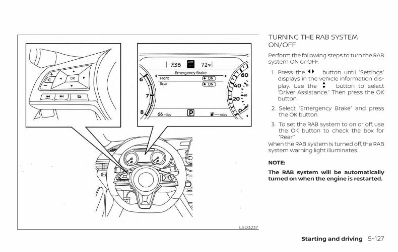
TURNING THE RAB SYSTEMON/OFFPerform the following steps to turn the RABsystem ON or OFF.
1. Press the button until “Settings”displays in the vehicle information dis-play. Use the button to select“Driver Assistance.” Then press the OKbutton.
2. Select “Emergency Brake” and pressthe OK button.
3. To set the RAB system to on or off, usethe OK button to check the box for“Rear.”
When the RAB system is turned off, the RABsystem warning light illuminates.
NOTE:
The RAB system will be automaticallyturned on when the engine is restarted.
LSD3237
Starting and driving 5-127
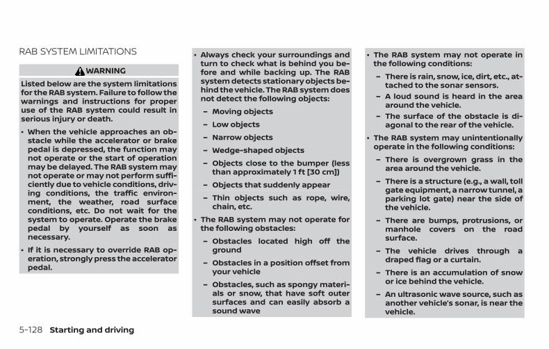
RAB SYSTEM LIMITATIONS
WARNINGListed below are the system limitationsfor the RAB system. Failure to follow thewarnings and instructions for properuse of the RAB system could result inserious injury or death.
∙ When the vehicle approaches an ob-stacle while the accelerator or brakepedal is depressed, the function maynot operate or the start of operationmay be delayed. The RAB system maynot operate or may not perform suffi-ciently due to vehicle conditions, driv-ing conditions, the traffic environ-ment, the weather, road surfaceconditions, etc. Do not wait for thesystem to operate. Operate the brakepedal by yourself as soon asnecessary.
∙ If it is necessary to override RAB op-eration, strongly press the acceleratorpedal.
∙ Always check your surroundings andturn to check what is behind you be-fore and while backing up. The RABsystem detects stationary objects be-hind the vehicle. The RAB system doesnot detect the following objects:
– Moving objects
– Low objects
– Narrow objects
– Wedge-shaped objects
– Objects close to the bumper (lessthan approximately 1 ft [30 cm])
– Objects that suddenly appear
– Thin objects such as rope, wire,chain, etc.
∙ The RAB system may not operate forthe following obstacles:
– Obstacles located high off theground
– Obstacles in a position offset fromyour vehicle
– Obstacles, such as spongy materi-als or snow, that have soft outersurfaces and can easily absorb asound wave
∙ The RAB system may not operate inthe following conditions:
– There is rain, snow, ice, dirt, etc., at-tached to the sonar sensors.
– A loud sound is heard in the areaaround the vehicle.
– The surface of the obstacle is di-agonal to the rear of the vehicle.
∙ The RAB system may unintentionallyoperate in the following conditions:
– There is overgrown grass in thearea around the vehicle.
– There is a structure (e.g., a wall, tollgate equipment, a narrow tunnel, aparking lot gate) near the side ofthe vehicle.
– There are bumps, protrusions, ormanhole covers on the roadsurface.
– The vehicle drives through adraped flag or a curtain.
– There is an accumulation of snowor ice behind the vehicle.
– An ultrasonic wave source, such asanother vehicle’s sonar, is near thevehicle.
5-128 Starting and driving
∙ Once the automatic brake controloperates, it does not operate again ifthe vehicle approaches the sameobstacle.
∙ The automatic brake control can onlyoperate for a short period of time.Therefore, the driver must depressthe brake pedal.
∙ In the following situations, the RABsystem may not operate properly ormay not function sufficiently:
– The vehicle is driven in badweather (rain, fog, snow, etc.).
– The vehicle is driven on a steep hill.
– The vehicle’s posture is changed(e.g., when driving over a bump).
– The vehicle is driven on a slipperyroad.
– The vehicle is turned sharply byturning the steering wheel fully.
– Snow chains are used.
– Wheels or tires other than NISSANrecommended are used.
– The brakes are cold at low ambienttemperatures or immediately afterdriving has started.
– The braking force becomes poordue to wet brakes after drivingthrough a puddle or washing thevehicle.
∙ Turn the RAB system off in the follow-ing conditions to prevent the occur-rence of an unexpected accidentresulting from sudden systemoperation:
– The vehicle is towed.
– The vehicle is carried on a flatbedtruck.
– The vehicle is on the chassisdynamometer.
– The vehicle drives on an unevenroad surface.
– Suspension parts other than thosedesignated as Genuine NISSANparts are used. (If the vehicleheight or the vehicle body inclina-tion is changed, the system maynot detect an obstacle correctly.)
∙ Excessive noise (e.g., audio systemvolume, an open vehicle window) willinterfere with the chime sound, and itmay not be heard.
SYSTEM MALFUNCTIONIf the RAB system malfunctions, it will beturned off automatically, the RAB systemwarning light will illuminate, and the “Sys-tem fault” warning message will appear inthe vehicle information display.
Action to take
If the warning light illuminates, park the ve-hicle in a safe location, turn the engine off,and restart the engine. If the warning lightcontinues to illuminate, have the RAB sys-tem checked. It is recommended that youvisit a NISSAN dealer for this service.
NOTE:
If the RAB system cannot be operatedtemporarily, the RAB system warninglight blinks.
Starting and driving 5-129
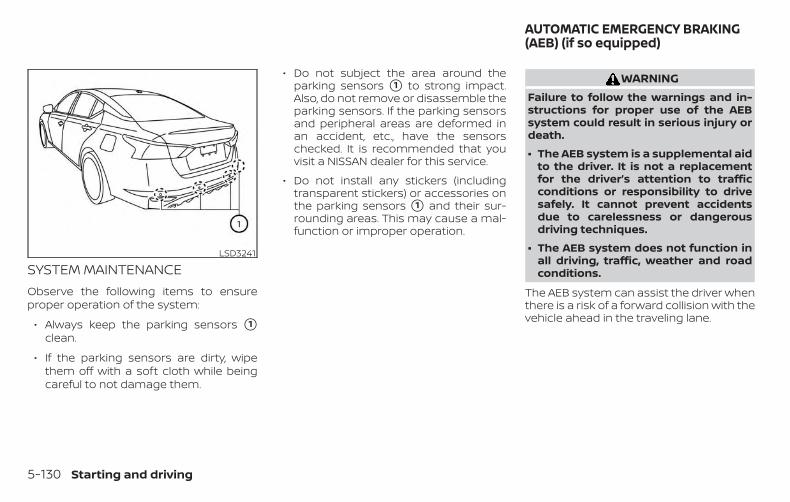
SYSTEM MAINTENANCEObserve the following items to ensureproper operation of the system:
∙ Always keep the parking sensors �1clean.
∙ If the parking sensors are dirty, wipethem off with a soft cloth while beingcareful to not damage them.
∙ Do not subject the area around theparking sensors �1 to strong impact.Also, do not remove or disassemble theparking sensors. If the parking sensorsand peripheral areas are deformed inan accident, etc., have the sensorschecked. It is recommended that youvisit a NISSAN dealer for this service.
∙ Do not install any stickers (includingtransparent stickers) or accessories onthe parking sensors �1 and their sur-rounding areas. This may cause a mal-function or improper operation.
WARNINGFailure to follow the warnings and in-structions for proper use of the AEBsystem could result in serious injury ordeath.
∙ The AEB system is a supplemental aidto the driver. It is not a replacementfor the driver’s attention to trafficconditions or responsibility to drivesafely. It cannot prevent accidentsdue to carelessness or dangerousdriving techniques.
∙ The AEB system does not function inall driving, traffic, weather and roadconditions.
The AEB system can assist the driver whenthere is a risk of a forward collision with thevehicle ahead in the traveling lane.
LSD3241
AUTOMATIC EMERGENCY BRAKING(AEB) (if so equipped)
5-130 Starting and driving
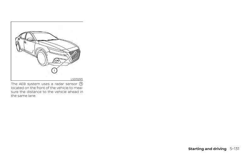
The AEB system uses a radar sensor �1located on the front of the vehicle to mea-sure the distance to the vehicle ahead inthe same lane.
LSD3293
Starting and driving 5-131
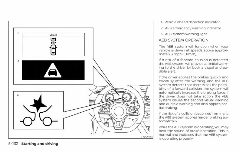
1. Vehicle ahead detection indicator
2. AEB emergency warning indicator
3. AEB system warning light
AEB SYSTEM OPERATIONThe AEB system will function when yourvehicle is driven at speeds above approxi-mately 3 mph (5 km/h).
If a risk of a forward collision is detected,the AEB system will provide an initial warn-ing to the driver by both a visual and au-dible alert.
If the driver applies the brakes quickly andforcefully after the warning, and the AEBsystem detects that there is still the possi-bility of a forward collision, the system willautomatically increase the braking force. Ifthe driver does not take action, the AEBsystem issues the second visual warningand audible warning and also applies par-tial braking.
If the risk of a collision becomes imminent,the AEB system applies harder braking au-tomatically.
While the AEB system is operating, you mayhear the sound of brake operation. This isnormal and indicates that the AEB systemis operating properly.LSD3281
5-132 Starting and driving
NOTE:
The vehicle’s brake lights come on whenbraking is performed by the AEB system.
Depending on vehicle speed and distanceto the vehicle ahead, as well as driving androadway conditions, the system may helpthe driver avoid a forward collision or mayhelp mitigate the consequences of a colli-sion, should one be unavoidable. If thedriver is handling the steering wheel, accel-erating or braking, the AEB system willfunction later or will not function.
The automatic braking will cease under thefollowing conditions:
∙ When the steering wheel is turned as faras necessary to avoid a collision.
∙ When the accelerator pedal is de-pressed.
∙ When there is no longer a vehicle de-tected ahead.
If the AEB system has stopped the vehicle,the vehicle will remain at a standstill forapproximately 2 seconds before thebrakes are released.
Starting and driving 5-133
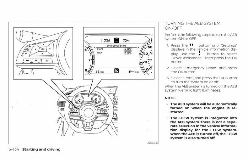
TURNING THE AEB SYSTEMON/OFFPerform the following steps to turn the AEBsystem ON or OFF.
1. Press the button until “Settings”displays in the vehicle information dis-play. Use the button to select“Driver Assistance.” Then press the OKbutton.
2. Select “Emergency Brake” and pressthe OK button.
3. Select “Front” and press the OK buttonto turn the system on or off.
When the AEB system is turned off, the AEBsystem warning light illuminates.
NOTE:
∙ The AEB system will be automaticallyturned on when the engine is re-started.
∙ The I-FCW system is integrated intothe AEB system There is not a sepa-rate selection in the vehicle informa-tion display for the I-FCW system.When the AEB is turned off, the I-FCWsystem is also turned off.
LSD3237
5-134 Starting and driving
AEB SYSTEM LIMITATIONS
WARNINGListed below are the system limitationsfor the AEB system. Failure to operatethe vehicle in accordance with thesesystem limitations could result in seri-ous injury or death.
∙ The AEB system cannot detect all ve-hicles under all conditions.
∙ The radar sensor does not detect thefollowing objects:
– Pedestrians, animals or obstaclesin the roadway.
– Oncoming vehicles.
– Crossing vehicles.
∙ The radar sensor has some perfor-mance limitations. If a stationary ve-hicle is in the vehicles’s path, the AEBsystem will not function when the ve-hicle is driven at speeds over approxi-mately 50 mph (80 km/h).
∙ The radar sensor may not detect avehicle ahead in the followingconditions:
– Dirt, ice, snow or other materialcovering the radar sensor.
– Interference by other radarsources.
– Snow or road spray from travelingvehicles.
– If the vehicle ahead is narrow (e.g.motorcycle).
– When driving on a steep downhillslope or roads with sharp curves.
∙ In some road or traffic conditions, theAEB system may unexpectedly applypartial braking. When acceleration isnecessary, continue to depress theaccelerator pedal to override thesystem.
∙ Braking distances increase on slip-pery surfaces.
∙ The system is designed to automati-cally check the sensor’s functionality,within certain limitations. The systemmay not detect some forms of ob-structions of the sensor area such asice, snow, stickers, etc. In these cases,the system may not be able to wornthe driver properly. Be sure that youcheck, clean and clear the sensor arearegularly.
∙ Excessive noise will interfere with thewarning chime sound, and the chimemay not be heard.
Starting and driving 5-135
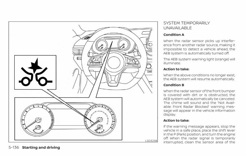
SYSTEM TEMPORARILYUNAVAILABLECondition A
When the radar sensor picks up interfer-ence from another radar source, making itimpossible to detect a vehicle ahead, theAEB system is automatically turned off.
The AEB system warning light (orange) willilluminate.
Action to take:
When the above conditions no longer exist,the AEB system will resume automatically.
Condition B
When the radar sensor of the front bumperis covered with dirt or is obstructed, theAEB system will automatically be canceled.The chime will sound and the “Not Avail-able: Front Radar Blocked” warning mes-sage will appear in the vehicle informationdisplay.
Action to take:
If the warning message appears, stop thevehicle in a safe place, place the shift leverin the P (Park) position, and turn the engineoff. When the radar signal is temporarilyinterrupted, clean the sensor area of theLSD3238
5-136 Starting and driving
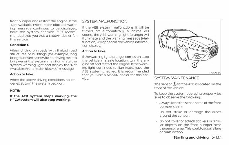
front bumper and restart the engine. If the“Not Available: Front Radar Blocked” warn-ing message continues to be displayed,have the system checked. It is recom-mended that you visit a NISSAN dealer forthis service.
Condition C
When driving on roads with limited roadstructures or buildings (for example, longbridges, deserts, snowfields, driving next tolong walls), the system may illuminate thesystem warning light and display the “NotAvailable: Front Radar Blocked” message.
Action to take:
When the above driving conditions no lon-ger exist, turn the system back on.
NOTE:
If the AEB system stops working, theI-FCW system will also stop working.
SYSTEM MALFUNCTIONIf the AEB system malfunctions, it will beturned off automatically, a chime willsound, the AEB warning light (orange) willilluminate and the warning message [Mal-function] will appear in the vehicle informa-tion display.
Action to take
If the warning light (orange) comes on, stopthe vehicle in a safe location, turn the en-gine off and restart the engine. If the warn-ing light continues to illuminate, have theAEB system checked. It is recommendedthat you visit a NISSAN dealer for this ser-vice. SYSTEM MAINTENANCE
The sensor �1 for the AEB is located on thefront of the vehicle.
To keep the system operating properly, besure to observe the following:
∙ Always keep the sensor area of the frontbumper clean.
∙ Do not strike or damage the areasaround the sensor.
∙ Do not cover or attach stickers or simi-lar objects on the front bumper nearthe sensor area. This could cause failureor malfunction.
LSD3293
Starting and driving 5-137
∙ Do not attach metallic objects near thesensor area (brush guard, etc.). Thiscould cause failure or malfunction.
∙ Do not alter, remove or paint the frontbumper. Before customizing or restor-ing the front bumper, it is recom-mended that you visit a NISSAN dealer.
Radio frequency statement
For USA
FCC ID OAYARS4B
This device complies with Part 15 of the FCCRules.
Operation is subject to the following twoconditions:
1. This device may not cause harmful in-terference, and
2. This device must accept any interfer-ence received, including interferencethat may cause undesired operation.
FCC Warning
Changes or modifications not expresslyapproved by the party responsible forcompliance could void the user’s authorityto operate the equipment.
This equipment has been tested and foundto comply with the limits for a Class A digi-tal device, pursuant to Part 15 of the FCCRules. These limits are designed to providereasonable protection against harmful in-terference when the equipment is oper-ated in a commercial environment. Thisequipment generates, uses, and can radi-ate radio frequency energy and, if not in-stalled and used in accordance with theinstruction manual, may cause harmful in-terference to radio communications. Op-eration of this equipment in a residentialarea is likely to cause harmful interferencein which case the user will be required tocorrect the interference at his own ex-pense.
Radio frequency radiation exposure infor-mation:
This equipment complies with FCC radia-tion exposure limits set forth for an uncon-trolled environment.
This equipment should be installed andoperated with minimum distance of 20 cmbetween the radiator and your body.
The transmitter must not be co-located oroperating in conjunction with any other an-tenna or transmitter.
For Canada
Model: ARS4–B
IC: 4135A-ARS4B
FCC ID: OAYARS4B
This device complies with Industry Canadalicence-exempt RSS standard(s). Operationis subject to the following two conditions:
1. This device may not cause interference,
2. This device must accept any interfer-ence, including interference that maycause undesired operation of the de-vice.
Le présent appareil est conforme aux CNRd’Industrie Canada applicables aux appar-eils radio exempts de licence. L’exploitationest autorisée aux deux conditions suiv-antes:
1. L’appareil ne doit pas produire debrouillage, et
2. L’utilisateur de l’appareil doit acceptertout brouillage radioélectrique subi,même si le brouillage est susceptibled’en compromettre le fonctionnement.
5-138 Starting and driving
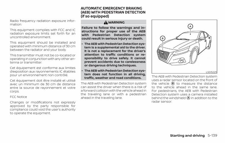
Radio frequency radiation exposure infor-mation:
This equipment complies with FCC and ICradiation exposure limits set forth for anuncontrolled environment.
This equipment should be installed andoperated with minimum distance of 30 cmbetween the radiator and your body.
This transmitter must not be co-located oroperating in conjunction with any other an-tenna or transmitter.
Cet équipement est conforme aux limitesd’exposition aux rayonnements IC établiespour un environnement non contrôlé.
Cet équipement doit être installé et utiliséavec un minimum de 30 cm de distanceentre la source de rayonnement et votrecorps.
FCC Notice
Changes or modifications not expresslyapproved by the party responsible forcompliance could void the user’s authorityto operate the equipment.
WARNINGFailure to follow the warnings and in-structions for proper use of the AEBwith Pedestrian Detection systemcould result in serious injury or death.
∙ The AEB with Pedestrian Detection sys-tem is a supplemental aid to the driver.It is not a replacement for the driver’sattention to traffic conditions or re-sponsibility to drive safely. It cannotprevent accidents due to carelessnessor dangerous driving techniques.
∙ The AEB with Pedestrian Detection sys-tem does not function in all driving,traffic, weather and road conditions.
The AEB with Pedestrian Detection systemcan assist the driver when there is a risk ofa forward collision with the vehicle ahead inthe traveling lane or with a pedestrianahead in the traveling lane.
The AEB with Pedestrian Detection systemuses a radar sensor located on the front ofthe vehicle �B to measure the distanceto the vehicle ahead in the same lane.For pedestrians, the AEB with PedestrianDetection system uses a camera installedbehind the windshield �A in addition to theradar sensor.
LSD3223
AUTOMATIC EMERGENCY BRAKING(AEB) WITH PEDESTRIAN DETECTION(if so equipped)
Starting and driving 5-139
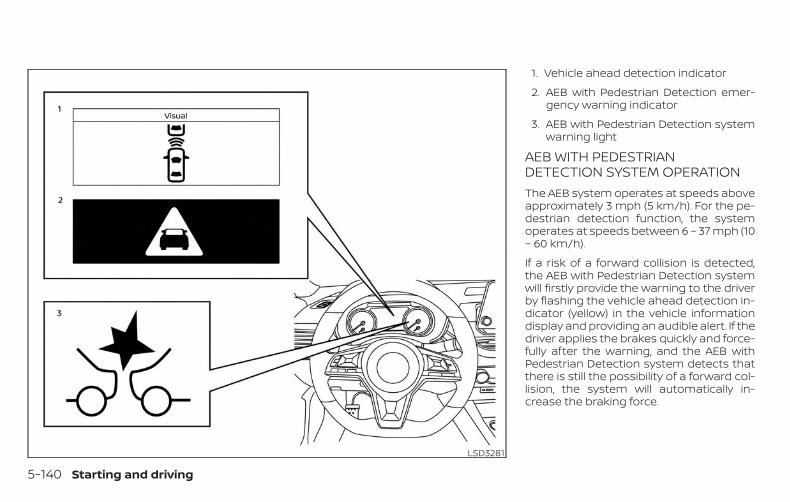
1. Vehicle ahead detection indicator
2. AEB with Pedestrian Detection emer-gency warning indicator
3. AEB with Pedestrian Detection systemwarning light
AEB WITH PEDESTRIANDETECTION SYSTEM OPERATIONThe AEB system operates at speeds aboveapproximately 3 mph (5 km/h). For the pe-destrian detection function, the systemoperates at speeds between 6 – 37 mph (10– 60 km/h).
If a risk of a forward collision is detected,the AEB with Pedestrian Detection systemwill firstly provide the warning to the driverby flashing the vehicle ahead detection in-dicator (yellow) in the vehicle informationdisplay and providing an audible alert. If thedriver applies the brakes quickly and force-fully after the warning, and the AEB withPedestrian Detection system detects thatthere is still the possibility of a forward col-lision, the system will automatically in-crease the braking force.
LSD3281
5-140 Starting and driving
If the driver does not take action, the AEBwith Pedestrian Detection system issuesthe second visual (flashing) (red and white)and audible warning. If the driver releasesthe accelerator pedal, then the system ap-plies partial braking. If the risk of a collisionbecomes imminent, the AEB with Pedes-trian Detection system applies harderbraking automatically.
While the AEB with Pedestrian Detectionsystem is operating, you may hear thesound of brake operation. This is normaland indicates that the AEB with PedestrianDetection system is operating properly.
NOTE:
The vehicle’s brake lights come on whenany braking is performed by the AEBwith Pedestrian Detection system.
Depending on vehicle speed and distanceto the vehicle or pedestrian ahead, as wellas driving and roadway conditions, the sys-tem may help the driver avoid a forwardcollision or may help mitigate the conse-quences if a collision should be unavoid-able. If the driver is handling the steeringwheel, accelerating or braking, the AEB withPedestrian Detection system will functionlater or will not function.
The automatic braking will cease under thefollowing conditions:
∙ When the steering wheel is turned toavoid a collision.
∙ When the accelerator pedal is de-pressed.
∙ When there is no longer a vehicle or apedestrian detected ahead.
If the AEB with Pedestrian Detection sys-tem has stopped the vehicle, the vehiclewill remain at a standstill for approximately2 seconds before the brakes are released.
Starting and driving 5-141
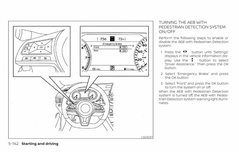
TURNING THE AEB WITHPEDESTRIAN DETECTION SYSTEMON/OFFPerform the following steps to enable ordisable the AEB with Pedestrian Detectionsystem.
1. Press the button until “Settings”displays in the vehicle information dis-play. Use the button to select“Driver Assistance.” Then press the OKbutton.
2. Select “Emergency Brake” and pressthe OK button.
3. Select “Front” and press the OK buttonto turn the system on or off.
When the AEB with Pedestrian Detectionsystem is turned off, the AEB with Pedes-trian Detection system warning light illumi-nates.
LSD3237
5-142 Starting and driving
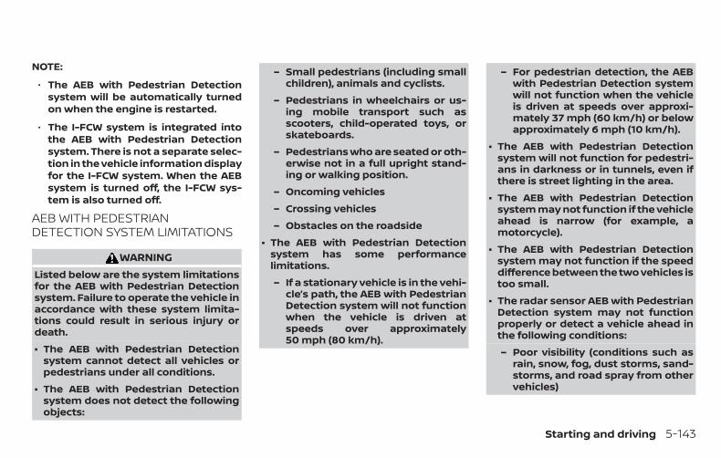
NOTE:
∙ The AEB with Pedestrian Detectionsystem will be automatically turnedon when the engine is restarted.
∙ The I-FCW system is integrated intothe AEB with Pedestrian Detectionsystem. There is not a separate selec-tion in the vehicle information displayfor the I-FCW system. When the AEBsystem is turned off, the I-FCW sys-tem is also turned off.
AEB WITH PEDESTRIANDETECTION SYSTEM LIMITATIONS
WARNINGListed below are the system limitationsfor the AEB with Pedestrian Detectionsystem. Failure to operate the vehicle inaccordance with these system limita-tions could result in serious injury ordeath.
∙ The AEB with Pedestrian Detectionsystem cannot detect all vehicles orpedestrians under all conditions.
∙ The AEB with Pedestrian Detectionsystem does not detect the followingobjects:
– Small pedestrians (including smallchildren), animals and cyclists.
– Pedestrians in wheelchairs or us-ing mobile transport such asscooters, child-operated toys, orskateboards.
– Pedestrians who are seated or oth-erwise not in a full upright stand-ing or walking position.
– Oncoming vehicles
– Crossing vehicles
– Obstacles on the roadside
∙ The AEB with Pedestrian Detectionsystem has some performancelimitations.
– If a stationary vehicle is in the vehi-cle’s path, the AEB with PedestrianDetection system will not functionwhen the vehicle is driven atspeeds over approximately50 mph (80 km/h).
– For pedestrian detection, the AEBwith Pedestrian Detection systemwill not function when the vehicleis driven at speeds over approxi-mately 37 mph (60 km/h) or belowapproximately 6 mph (10 km/h).
∙ The AEB with Pedestrian Detectionsystem will not function for pedestri-ans in darkness or in tunnels, even ifthere is street lighting in the area.
∙ The AEB with Pedestrian Detectionsystem may not function if the vehicleahead is narrow (for example, amotorcycle).
∙ The AEB with Pedestrian Detectionsystem may not function if the speeddifference between the two vehicles istoo small.
∙ The radar sensor AEB with PedestrianDetection system may not functionproperly or detect a vehicle ahead inthe following conditions:
– Poor visibility (conditions such asrain, snow, fog, dust storms, sand-storms, and road spray from othervehicles)
Starting and driving 5-143
– Driving on a steep downhill slopeor roads with sharp curves.
– Driving on a bumpy road surface,such as an uneven dirt road.
– If dirt, ice, snow or other material iscovering the radar sensor area.
– Interference by other radarsources.
– The camera area of the windshieldis fogged up, or covered with dirt,water drops, ice, snow, etc.
– Strong light (for example, sunlightor high beams from oncoming ve-hicles) enters the front camera.Strong light causes the areaaround the pedestrian to be cast ina shadow, making it difficult to see.
– A sudden change in brightness oc-curs. (For example, when the ve-hicle enters or exits a tunnel or ashaded area or lightning flashes.)
– The poor contrast of a person tothe background, such as havingclothing color or pattern which issimilar to the background.
– The pedestrian’s profile is partiallyobscured or unidentifiable due tothe pedestrian transporting lug-gage, wearing bulky or very loose-fitting clothing or accessories.
∙ The system performance may de-grade in the following conditions:
– The vehicle is driven on a slipperyroad.
– The vehicle is driven on a slope.
– Excessively heavy baggage isloaded in the rear seat or the trunkroom of your vehicle.
∙ The system is designed to automati-cally check the sensor’s (radar andcamera) functionality, within certainlimitations. The system may not de-tect blockage of sensor areas coveredby ice, snow or stickers, for example.In these cases, the system may not beable to warn the driver properly. Besure that you check, clean and clearsensor areas regularly.
∙ In some road and traffic conditions,the AEB with Pedestrian Detectionsystem may unexpectedly apply par-tial braking. When acceleration is nec-essary, depress the accelerator pedalto override the system.
∙ Excessive noise will interfere with thewarning chime sound, and the chimemay not be heard.
5-144 Starting and driving
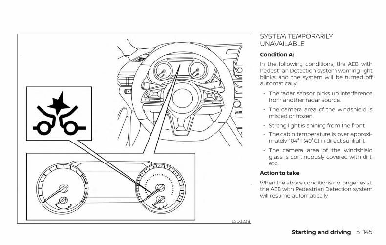
SYSTEM TEMPORARILYUNAVAILABLECondition A:
In the following conditions, the AEB withPedestrian Detection system warning lightblinks and the system will be turned offautomatically:
∙ The radar sensor picks up interferencefrom another radar source.
∙ The camera area of the windshield ismisted or frozen.
∙ Strong light is shining from the front.∙ The cabin temperature is over approxi-
mately 104°F (40°C) in direct sunlight.
∙ The camera area of the windshieldglass is continuously covered with dirt,etc.
Action to take
When the above conditions no longer exist,the AEB with Pedestrian Detection systemwill resume automatically.
LSD3238
Starting and driving 5-145
NOTE:
When the inside of the windshield on thecamera area is misted or frozen, it willtake a period of time to remove it afterthe A/C turns on. If dirt appears on thisarea, it is recommended that you visit aNISSAN dealer.
Condition B:
When the radar sensor of the front bumperis covered with dirt or is obstructed, theAEB with Pedestrian Detection system willautomatically be canceled. The chime willsound and the “Not Available: Front RadarBlocked” warning message will appear inthe vehicle information display.
Action to take:
If the warning message appears, stop thevehicle in a safe place, place the shift leverin the P (Park) position, and turn the engineoff. When the radar signal is temporarilyinterrupted, clean the sensor area of thefront bumper and restart the engine. If the“Not Available: Front Radar Blocked” warn-ing message continues to be displayed,have the system checked. It is recom-mended that you visit a NISSAN dealer forthis service.
Condition C
When driving on roads with limited roadstructures or buildings (for example, longbridges, deserts, snowfields, driving next tolong walls), the system may illuminate thesystem warning light and display the “NotAvailable: Front Radar Blocked” message.
Action to take:
When the above driving conditions no lon-ger exist, turn the system back on.
NOTE:
If the AEB with Pedestrian Detection sys-tem stops working, the I-FCW system willalso stop working.
SYSTEM MALFUNCTIONIf the AEB with Pedestrian Detection sys-tem malfunctions, it will be turned off auto-matically, a chime will sound, the AEB withPedestrian Detection system warning light(orange) will illuminate and the warningmessage [Malfunction] will appear in thevehicle information display.
Action to take
If the warning light (orange) comes on, stopthe vehicle in a safe location, turn the en-gine off and restart the engine. If the warn-ing light continues to illuminate, have theAEB with Pedestrian Detection systemchecked. It is recommended that you visit aNISSAN dealer for this service.
5-146 Starting and driving
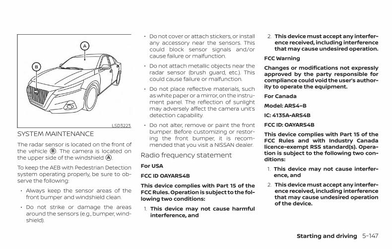
SYSTEM MAINTENANCEThe radar sensor is located on the front ofthe vehicle �B . The camera is located onthe upper side of the windshield �A .
To keep the AEB with Pedestrian Detectionsystem operating properly, be sure to ob-serve the following:
∙ Always keep the sensor areas of thefront bumper and windshield clean.
∙ Do not strike or damage the areasaround the sensors (e.g., bumper, wind-shield).
∙ Do not cover or attach stickers, or installany accessory near the sensors. Thiscould block sensor signals and/orcause failure or malfunction.
∙ Do not attach metallic objects near theradar sensor (brush guard, etc.). Thiscould cause failure or malfunction.
∙ Do not place reflective materials, suchas white paper or a mirror, on the instru-ment panel. The reflection of sunlightmay adversely affect the camera unit’sdetection capability.
∙ Do not alter, remove or paint the frontbumper. Before customizing or restor-ing the front bumper, it is recom-mended that you visit a NISSAN dealer.
Radio frequency statementFor USA
FCC ID OAYARS4B
This device complies with Part 15 of theFCC Rules. Operation is subject to the fol-lowing two conditions:
1. This device may not cause harmfulinterference, and
2. This device must accept any interfer-ence received, including interferencethat may cause undesired operation.
FCC Warning
Changes or modifications not expresslyapproved by the party responsible forcompliance could void the user’s author-ity to operate the equipment.
For Canada
Model: ARS4–B
IC: 4135A-ARS4B
FCC ID: OAYARS4B
This device complies with Part 15 of theFCC Rules and with Industry Canadalicence-exempt RSS standard(s). Opera-tion is subject to the following two con-ditions:
1. This device may not cause interfer-ence, and
2. This device must accept any interfer-ence received, including interferencethat may cause undesired operationof the device.
LSD3223
Starting and driving 5-147
Le présent appareil est conforme auxCNR d’Industrie Canada applicables auxappareils radio exempts de licence.L’exploitation est autorisée aux deuxconditions suivantes:
1. L’appareil ne doit pas produire debrouillage, et
2. L’utilisateur de l’appareil doit ac-cepter tout brouillage radioélec-trique subi, même si le brouillage estsusceptible d’en compromettre lefonctionnement.
Radio frequency radiation exposure in-formation:
This equipment complies with FCC and ICradiation exposure limits set forth for anuncontrolled environment.
This equipment should be installed andoperated with minimum distance of30 cm between the radiator and yourbody.
This transmitter must not be co-locatedor operating in conjunction with anyother antenna or transmitter.
Cet équipement est conforme aux lim-ites d’exposition aux rayonnements ICétablies pour un environnement noncontrôlé.
Cet équipement doit être installé etutilisé avec un minimum de 30 cm dedistance entre la source de rayonnementet votre corps.
FCC Notice
Changes or modifications not expresslyapproved by the party responsible forcompliance could void the user’s author-ity to operate the equipment.
WARNINGFailure to follow the warnings and in-structions for proper use of the I-FCWsystem could result in serious injury ordeath.
∙ The I-FCW system can help warn thedriver before a collision occurs but willnot avoid a collision. It is the driver’sresponsibility to stay alert, drivesafely and be in control of the vehicleat all times.
The I-FCW system can help alert the driverwhen there is a sudden braking of a secondvehicle traveling in front of the vehicleahead in the same lane.
INTELLIGENT FORWARD COLLISIONWARNING (I-FCW)
5-148 Starting and driving

The I-FCW system uses a radar sensor �1located on the front of the vehicle to mea-sure the distance to the vehicle ahead inthe same lane.
LSD3293
Starting and driving 5-149
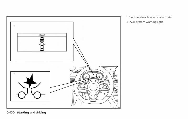
1. Vehicle ahead detection indicator
2. AEB system warning light
LSD3282
5-150 Starting and driving
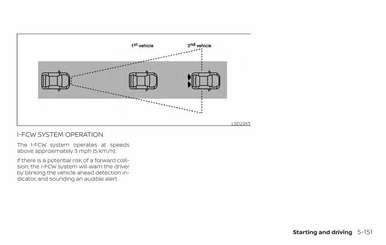
I-FCW SYSTEM OPERATIONThe I-FCW system operates at speedsabove approximately 3 mph (5 km/h).
If there is a potential risk of a forward colli-sion, the I-FCW system will warn the driverby blinking the vehicle ahead detection in-dicator, and sounding an audible alert.
LSD2263
Starting and driving 5-151

TURNING THE I-FCW SYSTEMON/OFFPerform the following steps to turn theI-FCW system ON or OFF.
1. Press the button until “Settings”displays in the vehicle information dis-play. Use the button to select“Driver Assistance.” Then press the OKbutton.
2. Select “Emergency Brake” and pressthe OK button.
3. Select “Front” and press the OK buttonto turn the system on or off.
When the I-FCW system is turned off, theAEB system warning light illuminates.
NOTE:
∙ The I-FCW system will be automati-cally turned on when the engine isrestarted.
∙ The I-FCW system is integrated intothe AEB system. There is not a sepa-rate selection in the vehicle informa-tion display for the I-FCW system.When the AEB is turned off, the I-FCWsystem is also turned off.
LSD3237
5-152 Starting and driving
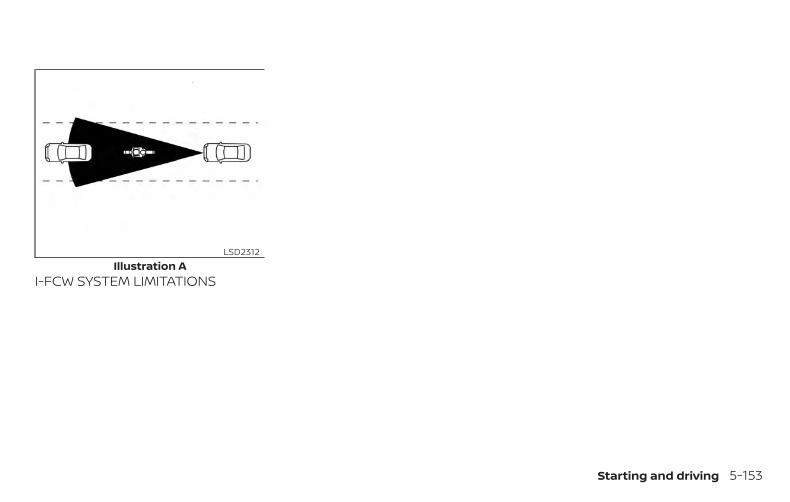
I-FCW SYSTEM LIMITATIONSIllustration A
LSD2312
Starting and driving 5-153
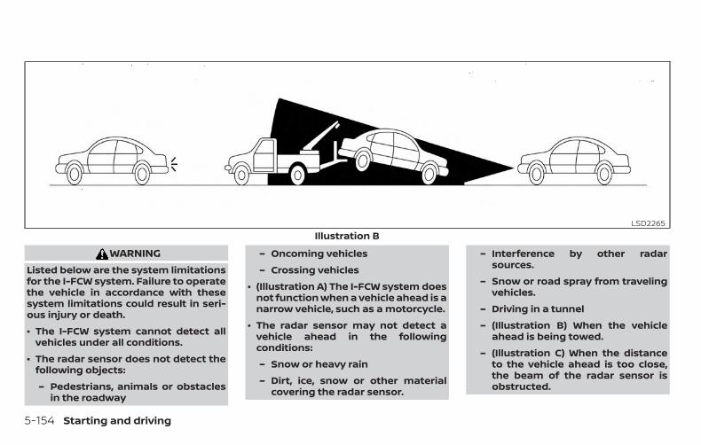
WARNINGListed below are the system limitationsfor the I-FCW system. Failure to operatethe vehicle in accordance with thesesystem limitations could result in seri-ous injury or death.
∙ The I-FCW system cannot detect allvehicles under all conditions.
∙ The radar sensor does not detect thefollowing objects:
– Pedestrians, animals or obstaclesin the roadway
– Oncoming vehicles
– Crossing vehicles
∙ (Illustration A) The I-FCW system doesnot function when a vehicle ahead is anarrow vehicle, such as a motorcycle.
∙ The radar sensor may not detect avehicle ahead in the followingconditions:
– Snow or heavy rain
– Dirt, ice, snow or other materialcovering the radar sensor.
– Interference by other radarsources.
– Snow or road spray from travelingvehicles.
– Driving in a tunnel
– (Illustration B) When the vehicleahead is being towed.
– (Illustration C) When the distanceto the vehicle ahead is too close,the beam of the radar sensor isobstructed.
Illustration BLSD2265
5-154 Starting and driving
– (Illustration D) When driving on asteep downhill slope or roads withsharp curves.
∙ The system is designed to automati-cally check the sensor’s functionality,within certain limitations. The systemmay not detect some forms of ob-struction of the sensor area such asice, snow, stickers, etc. In these cases,the system may not be able to warnthe driver properly. Be sure that youcheck, clean and clear the sensor arearegularly.
∙ Excessive noise will interfere with thewarning chime sound, and the chimemay not be heard.
Starting and driving 5-155
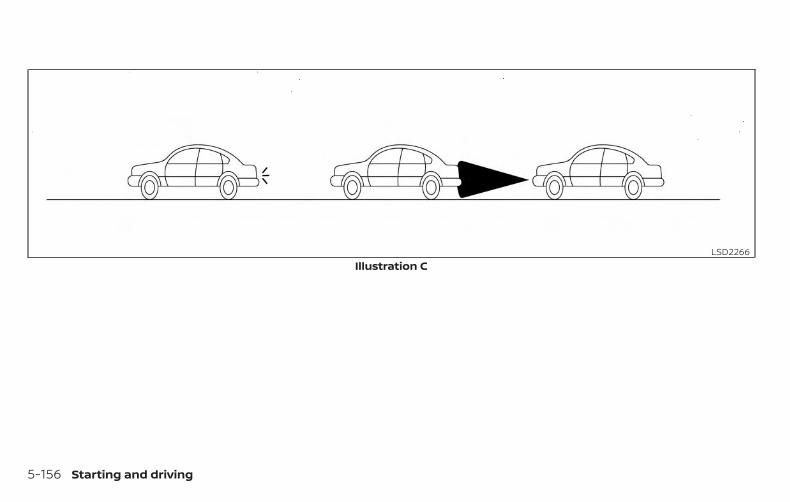
Illustration CLSD2266
5-156 Starting and driving
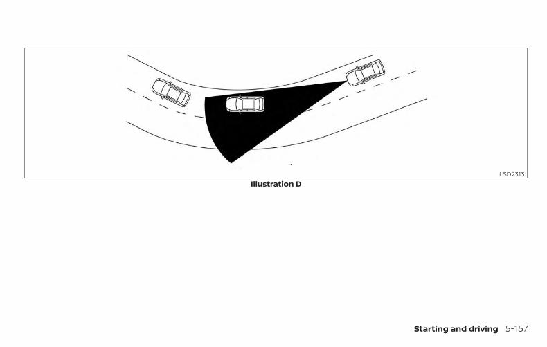
Illustration DLSD2313
Starting and driving 5-157
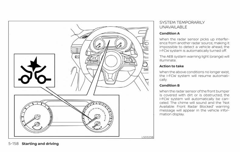
SYSTEM TEMPORARILYUNAVAILABLECondition A
When the radar sensor picks up interfer-ence from another radar source, making itimpossible to detect a vehicle ahead, theI-FCW system is automatically turned off.
The AEB system warning light (orange) willilluminate.
Action to take
When the above conditions no longer exist,the I-FCW system will resume automati-cally.
Condition B
When the radar sensor of the front bumperis covered with dirt or is obstructed, theI-FCW system will automatically be can-celed. The chime will sound and the “NotAvailable: Front Radar Blocked” warningmessage will appear in the vehicle infor-mation display.
LSD3238
5-158 Starting and driving
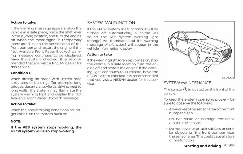
Action to take:
If the warning message appears, stop thevehicle in a safe place, place the shift leverin the P (Park) position, and turn the engineoff. When the radar signal is temporarilyinterrupted, clean the sensor area of thefront bumper and restart the engine. If the“Not Available: Front Radar Blocked” warn-ing message continues to be displayed,have the system checked. It is recom-mended that you visit a NISSAN dealer forthis service.
Condition C
When driving on roads with limited roadstructures or buildings (for example, longbridges, deserts, snowfields, driving next tolong walls), the system may illuminate thesystem warning light and display the “NotAvailable: Front Radar Blocked” message.
Action to take:
When the above driving conditions no lon-ger exist, turn the system back on.
NOTE:
If the AEB system stops working, theI-FCW system will also stop working.
SYSTEM MALFUNCTIONIf the I-FCW system malfunctions, it will beturned off automatically, a chime willsound, the AEB system warning light(orange) will illuminate and the warningmessage [Malfunction] will appear in thevehicle information display.
Action to take
If the warning light (orange) comes on, stopthe vehicle in a safe location, turn the en-gine off and restart the engine. If the warn-ing light continues to illuminate, have theI-FCW system checked. It is recommendedthat you visit a NISSAN dealer for this ser-vice. SYSTEM MAINTENANCE
The sensor �1 is located on the front of thevehicle.
To keep the system operating properly, besure to observe the following:
∙ Always keep the sensor area of the frontbumper clean.
∙ Do not strike or damage the areasaround the sensor.
∙ Do not cover or attach stickers or simi-lar objects on the front bumper nearthe sensor area. This could cause failureor malfunction.
LSD3293
Starting and driving 5-159
∙ Do not attach metallic objects near thesensor area (brush guard, etc.). Thiscould cause failure or malfunction.
∙ Do not alter, remove or paint the frontbumper. Before customizing or restor-ing the front bumper, it is recom-mended that you visit a NISSAN dealer.
FCC Notice
For USA
This device complies with Part 15 of theFCC Rules. Operation is subject to the fol-lowing two conditions:
1. This device may not cause harmfulinterference, and
2. This device must accept any interfer-ence received, including interferencethat may cause undesired operation.
FCC Warning
Changes or modifications not expresslyapproved by the party responsible forcompliance could void the user’s author-ity to operate the equipment.
For Canada
This device complies with IndustryCanada licence-exempt RSS standard(s).Operation is subject to the following twoconditions:
1. This device may not cause interfer-ence,
2. This device must accept any interfer-ence, including interference thatmay cause undesired operation ofthe device.
WARNINGFailure to follow the warnings and in-structions for proper use of the I-DAsystem could result in serious injury ordeath.
∙ The I–DA system is only a warning toinform the driver of a potential lack ofdriver attention or drowsiness. It willnot steer the vehicle or prevent loss ofcontrol.
∙ The I–DA system does not detect andprovide an alert of the driver’s lack ofattention or fatigue in every situation.
∙ It is the driver’s responsibility to:
∙ stay alert,
∙ drive safely,
∙ keep the vehicle in the travelinglane,
∙ be in control of the vehicle at alltimes,
∙ avoid driving when tired,
∙ avoid distractions (texting, etc).
INTELLIGENT DRIVER ALERTNESS(I-DA)
5-160 Starting and driving
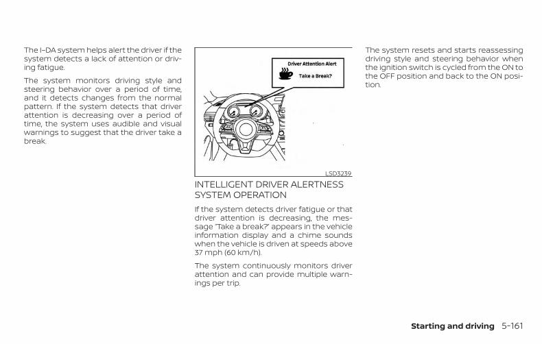
The I–DA system helps alert the driver if thesystem detects a lack of attention or driv-ing fatigue.
The system monitors driving style andsteering behavior over a period of time,and it detects changes from the normalpattern. If the system detects that driverattention is decreasing over a period oftime, the system uses audible and visualwarnings to suggest that the driver take abreak.
INTELLIGENT DRIVER ALERTNESSSYSTEM OPERATIONIf the system detects driver fatigue or thatdriver attention is decreasing, the mes-sage “Take a break?” appears in the vehicleinformation display and a chime soundswhen the vehicle is driven at speeds above37 mph (60 km/h).
The system continuously monitors driverattention and can provide multiple warn-ings per trip.
The system resets and starts reassessingdriving style and steering behavior whenthe ignition switch is cycled from the ON tothe OFF position and back to the ON posi-tion.
LSD3239
Starting and driving 5-161
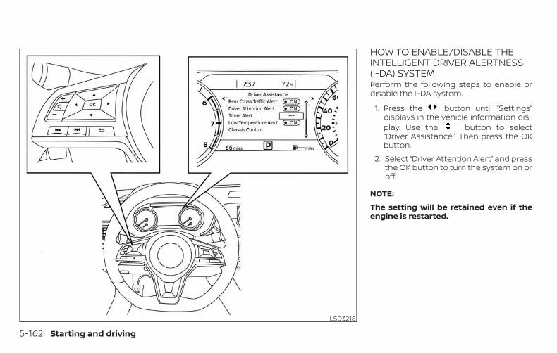
HOW TO ENABLE/DISABLE THEINTELLIGENT DRIVER ALERTNESS(I-DA) SYSTEMPerform the following steps to enable ordisable the I–DA system.
1. Press the button until “Settings”displays in the vehicle information dis-play. Use the button to select“Driver Assistance.” Then press the OKbutton.
2. Select “Driver Attention Alert” and pressthe OK button to turn the system on oroff.
NOTE:
The setting will be retained even if theengine is restarted.
LSD3218
5-162 Starting and driving
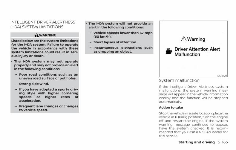
INTELLIGENT DRIVER ALERTNESS(I-DA) SYSTEM LIMITATIONS
WARNINGListed below are the system limitationsfor the I–DA system. Failure to operatethe vehicle in accordance with thesesystem limitations could result in seri-ous injury or death.
∙ The I-DA system may not operateproperly and may not provide an alertin the following conditions:
– Poor road conditions such as anuneven road surface or pot holes.
– Strong side wind.
– If you have adopted a sporty driv-ing style with higher corneringspeeds or higher rates ofacceleration.
– Frequent lane changes or changesto vehicle speed.
∙ The I–DA system will not provide analert in the following conditions:
– Vehicle speeds lower than 37 mph(60 km/h).
– Short lapses of attention.
– Instantaneous distractions suchas dropping an object.
System malfunctionIf the Intelligent Driver Alertness systemmalfunctions, the system warning mes-sage will appear in the vehicle informationdisplay and the function will be stoppedautomatically.
Action to take
Stop the vehicle in a safe location, place thevehicle in P (Park) position, turn the engineoff and restart the engine. If the systemwarning message continues to appear,have the system checked. It is recom-mended that you visit a NISSAN dealer forthis service.
LIC3125
Starting and driving 5-163
CAUTIONDuring the first 1,200 miles (2,000 km),follow these recommendations to ob-tain maximum engine performanceand ensure the future reliability andeconomy of your new vehicle. Failure tofollow these recommendations may re-sult in shortened engine life and re-duced engine performance.
∙ Avoid driving for long periods at con-stant speed, either fast or slow, and donot run the engine over 4,000 rpm.
∙ Do not accelerate at full throttle in anygear.
∙ Avoid quick starts.
∙ Avoid hard braking as much as pos-sible.
Follow these easy-to-use Fuel EfficientDriving Tips to help you achieve the mostfuel economy from your vehicle.
1. Use Smooth Accelerator and BrakePedal Application
∙ Avoid rapid starts and stops.
∙ Use smooth, gentle accelerator andbrake application whenever possible.
∙ Maintain constant speed while com-muting and coast whenever pos-sible.
2. Maintain Constant Speed
∙ Look ahead to try and anticipate andminimize stops.
∙ Synchronizing your speed with trafficlights allows you to reduce your num-ber of stops.
∙ Maintaining a steady speed can mini-mize red light stops and improve fuelefficiency.
3. Use Air Conditioning (A/C) at HigherVehicle Speeds
∙ Below 40 mph (64 km/h), it is moreefficient to open windows to cool thevehicle due to reduced engine load.
∙ Above 40 mph (64 km/h), it is moreefficient to use A/C to cool the vehicledue to increased aerodynamic drag.
∙ Recirculating the cool air in the cabinwhen the A/C is on reduces coolingload.
4. Drive at Economical Speeds andDistances
∙ Observing the speed limit and notexceeding 60 mph (97 km/h) (wherelegally allowed) can improve fuel effi-ciency due to reduced aerodynamicdrag.
∙ Maintaining a safe following distancebehind other vehicles reduces un-necessary braking.
∙ Safely monitoring traffic to anticipatechanges in speed permits reducedbraking and smooth accelerationchanges.
∙ Select a gear range suitable to roadconditions.
BREAK-IN SCHEDULE FUEL EFFICIENT DRIVING TIPS
5-164 Starting and driving
5. Use Cruise Control
∙ Using cruise control during highwaydriving helps maintain a steadyspeed.
∙ Cruise control is particularly effectivein providing fuel savings when drivingon flat terrains.
6. Plan for the Shortest Route
∙ Utilize a map or navigation system todetermine the best route to savetime.
7. Avoid Idling
∙ Shutting off your engine when safefor stops exceeding 30–60 secondssaves fuel and reduces emissions.
8. Buy an Automated Pass for TollRoads
∙ Automated passes permit drivers touse special lanes to maintain cruis-ing speed through the toll and avoidstopping and starting.
9. Winter Warm Up
∙ Limit idling time to minimize impactto fuel economy.
∙ Vehicles typically need no more than30 seconds of idling at start-up toeffectively circulate the engine oil be-fore driving.
∙ Your vehicle will reach its ideal oper-ating temperature more quicklywhile driving versus idling.
10. Keeping your Vehicle Cool
∙ Park your vehicle in a covered parkingarea or in the shade whenever pos-sible.
∙ When entering a hot vehicle, openingthe windows will help to reduce theinside temperature faster, resulting inreduced demand on your A/C sys-tem.
∙ Keep your engine tuned up.
∙ Follow the recommended scheduledmaintenance.
∙ Keep the tires inflated to the correctpressure. Low tire pressure increasestire wear and lowers fuel economy.
∙ Keep the wheels in correct alignment.Improper alignment increases tire wearand lowers fuel economy.
∙ Use the recommended viscosity engineoil. For additional information, refer to“Engine oil and oil filter recommenda-tions” in the “Technical and consumerinformation” section of this manual.
INCREASING FUEL ECONOMY
Starting and driving 5-165
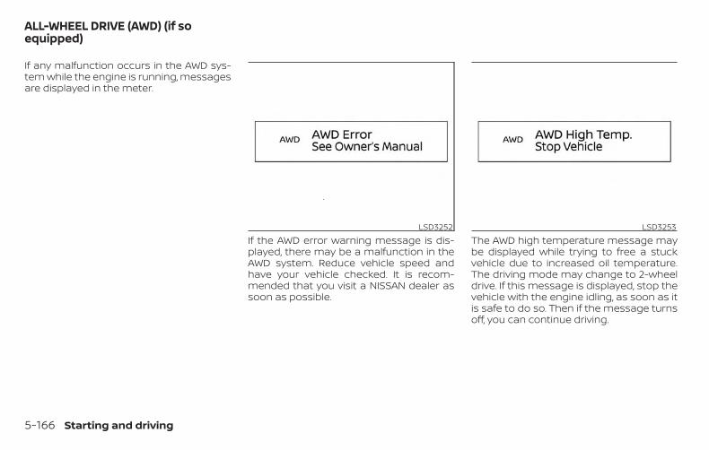
If any malfunction occurs in the AWD sys-tem while the engine is running, messagesare displayed in the meter.
If the AWD error warning message is dis-played, there may be a malfunction in theAWD system. Reduce vehicle speed andhave your vehicle checked. It is recom-mended that you visit a NISSAN dealer assoon as possible.
The AWD high temperature message maybe displayed while trying to free a stuckvehicle due to increased oil temperature.The driving mode may change to 2-wheeldrive. If this message is displayed, stop thevehicle with the engine idling, as soon as itis safe to do so. Then if the message turnsoff, you can continue driving.
LSD3252 LSD3253
ALL-WHEEL DRIVE (AWD) (if soequipped)
5-166 Starting and driving
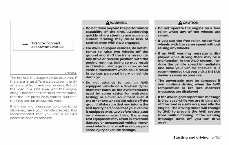
The tire size message may be displayed ifthere is a large difference between the di-ameters of front and rear wheels. Pull offthe road in a safe area, with the engineidling. Check that all tire sizes are the same,that the tire pressure is correct and thatthe tires are not excessively worn.
If any warning messages continue to bedisplayed, have your vehicle checked. It isrecommended that you visit a NISSANdealer as soon as possible.
WARNING∙ Do not drive beyond the performance
capability of the tires. Acceleratingquickly, sharp steering maneuvers orsudden braking may cause loss ofcontrol, even with AWD engaged.
∙ For AWD equipped vehicles, do not at-tempt to raise two wheels off theground and shift the transmission toany drive or reverse position with theengine running. Doing so may resultin drivetrain damage or unexpectedvehicle movement which could resultin serious personal injury or vehicledamage.
∙ Do not attempt to test an AWDequipped vehicle on a 2-wheel dyna-mometer (such as the dynamometersused by some states for emissionstesting) or similar equipment even ifthe other two wheels are raised off theground. Make sure that you inform thetest facility personnel that your vehicleis equipped with AWD before it is placedon a dynamometer. Using the wrongtest equipment may result in drivetraindamage or unexpected vehicle move-ment which could result in serious per-sonal injury or vehicle damage.
CAUTION∙ Do not operate the engine on a free
roller when any of the wheels areraised.
∙ If you use the free roller, rotate fourwheels with the same speed withoutraising any wheels.
∙ If an AWD warning message is dis-played while driving there may be amalfunction in the AWD system. Re-duce the vehicle speed immediatelyand have your vehicle checked. It isrecommended that you visit a NISSANdealer as soon as possible.
∙ The powertrain may be damaged ifyou continue driving when the AWDtemperature or tire size incorrectmessages are displayed
∙ If the AWD high temperature messageis displayed while you are driving, pulloff the road in a safe area, and idle theengine. The driving mode will changeto 2WD to prevent the AWD systemfrom malfunctioning. If the warningmessage turns off, you can driveagain.
LSD3254
Starting and driving 5-167
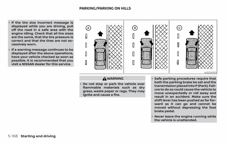
∙ If the tire size incorrect message isdisplayed while you are driving, pulloff the road in a safe area with theengine idling. Check that all tire sizesare the same, that the tire pressure iscorrect and that the tires are not ex-cessively worn.
∙ If a warning message continues to bedisplayed after the above operations,have your vehicle checked as soon aspossible. It is recommended that youvisit a NISSAN dealer for this service.
WARNING∙ Do not stop or park the vehicle over
flammable materials such as drygrass, waste paper or rags. They mayignite and cause a fire.
∙ Safe parking procedures require thatboth the parking brake be set and thetransmission placed into P (Park). Fail-ure to do so could cause the vehicle tomove unexpectedly or roll away andresult in an accident. Make sure theshift lever has been pushed as far for-ward as it can go and cannot bemoved without depressing the footbrake pedal.
∙ Never leave the engine running whilethe vehicle is unattended.
WSD0050
PARKING/PARKING ON HILLS
5-168 Starting and driving
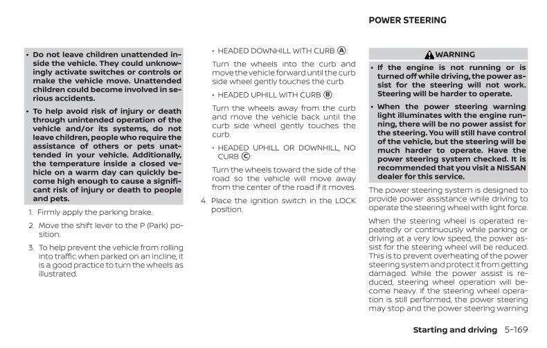
∙ Do not leave children unattended in-side the vehicle. They could unknow-ingly activate switches or controls ormake the vehicle move. Unattendedchildren could become involved in se-rious accidents.
∙ To help avoid risk of injury or deaththrough unintended operation of thevehicle and/or its systems, do notleave children, people who require theassistance of others or pets unat-tended in your vehicle. Additionally,the temperature inside a closed ve-hicle on a warm day can quickly be-come high enough to cause a signifi-cant risk of injury or death to peopleand pets.
1. Firmly apply the parking brake.
2. Move the shift lever to the P (Park) po-sition.
3. To help prevent the vehicle from rollinginto traffic when parked on an incline, itis a good practice to turn the wheels asillustrated.
∙ HEADED DOWNHILL WITH CURB �A :
Turn the wheels into the curb andmove the vehicle forward until the curbside wheel gently touches the curb.
∙ HEADED UPHILL WITH CURB �B :
Turn the wheels away from the curband move the vehicle back until thecurb side wheel gently touches thecurb.
∙ HEADED UPHILL OR DOWNHILL, NOCURB �C :
Turn the wheels toward the side of theroad so the vehicle will move awayfrom the center of the road if it moves.
4. Place the ignition switch in the LOCKposition.
WARNING∙ If the engine is not running or is
turned off while driving, the power as-sist for the steering will not work.Steering will be harder to operate.
∙ When the power steering warninglight illuminates with the engine run-ning, there will be no power assist forthe steering. You will still have controlof the vehicle, but the steering will bemuch harder to operate. Have thepower steering system checked. It isrecommended that you visit a NISSANdealer for this service.
The power steering system is designed toprovide power assistance while driving tooperate the steering wheel with light force.
When the steering wheel is operated re-peatedly or continuously while parking ordriving at a very low speed, the power as-sist for the steering wheel will be reduced.This is to prevent overheating of the powersteering system and protect it from gettingdamaged. While the power assist is re-duced, steering wheel operation will be-come heavy. If the steering wheel opera-tion is still performed, the power steeringmay stop and the power steering warning
POWER STEERING
Starting and driving 5-169
light will illuminate. In a safe location, stopthe engine and place the ignition switch inthe OFF position. The temperature of thepower steering system will go down after aperiod of time and the power assist levelwill return to normal after starting the en-gine. The power steering warning light willgo off. Avoid repeating such steering wheeloperations that could cause the powersteering system to overheat.
You may hear a noise from the front of thevehicle when the steering wheel is oper-ated. This is a normal operational noiseand is not a malfunction.
If the power steering warning light illumi-nates while the engine is running, it mayindicate the power steering system is notfunctioning properly and may need servic-ing. Have the power steering systemchecked. It is recommended that you visit aNISSAN dealer for this service.
When the power steering warning light illu-minates with the engine running, thepower assist for the steering will cease op-eration but you will still have control of thevehicle. At this time, greater steering effortsare required to operate the steering wheel,especially in sharp turns and at low speeds.
The brake system has two separate hy-draulic circuits. If one circuit malfunctions,you will still have braking at two wheels.
BRAKE PRECAUTIONSVacuum assisted brakesThe brake booster aids braking by usingengine vacuum. If the engine stops, youcan stop the vehicle by depressing thebrake pedal. However, greater foot pres-sure on the brake pedal will be required tostop the vehicle and stopping distance willbe longer.
Using the brakesAvoid resting your foot on the brake pedalwhile driving. This will overheat the brakes,wear out the brake pads faster, and reducegas mileage.
To help reduce brake wear and to preventthe brakes from overheating, reduce speedand downshift to a lower gear before goingdown a slope or long grade. Overheatedbrakes may reduce braking performanceand could result in loss of vehicle control.
WARNING∙ While driving on a slippery surface, be
careful when braking, accelerating ordownshifting. Abrupt braking or ac-celerating could cause the wheels toskid and result in an accident.
∙ If the engine is not running or isturned off while driving, the powerassist for the brakes will not work.Braking will be harder.
Wet brakesWhen the vehicle is washed or driventhrough water, the brakes may get wet. Asa result, your braking distance will be lon-ger and the vehicle may pull to one sideduring braking.
To dry the brakes, drive the vehicle at a safespeed while lightly pressing the brakepedal to heat up the brakes. Do this untilthe brakes return to normal. Avoid drivingthe vehicle at high speeds until the brakesfunction correctly.
BRAKE SYSTEM
5-170 Starting and driving
Parking brake break-inBreak in the parking brake shoes wheneverthe stopping effect of the parking brake isweakened or whenever the parking brakeshoes and/or drums/rotors are replaced,in order to assure the best braking perfor-mance.
This procedure is described in the vehicleservice manual. It is recommended thatyou visit a NISSAN dealer for this service.
ANTI-LOCK BRAKING SYSTEM (ABS)
WARNING∙ The ABS is a sophisticated device, but
it cannot prevent accidents resultingfrom careless or dangerous drivingtechniques. It can help maintain ve-hicle control during braking on slip-pery surfaces. Remember that stop-ping distances on slippery surfaceswill be longer than on normal sur-faces even with ABS. Stopping dis-tances may also be longer on rough,gravel or snow covered roads, or if youare using tire chains. Always maintaina safe distance from the vehicle infront of you. Ultimately, the driver isresponsible for safety.
∙ Tire type and condition may also af-fect braking effectiveness.
– When replacing tires, install thespecified size of tires on all fourwheels.
– When installing a spare tire, makesure that it is the proper size andtype as specified on the Tire andLoading Information label. For ad-ditional information, refer to “Tireand Loading Information label” inthe “Technical and consumer infor-mation” section of this manual.
– For additional information, refer to“Wheels and tires” in the “Do-it-yourself” section of this manual.
The ABS controls the brakes so the wheelsdo not lock during hard braking or whenbraking on slippery surfaces. The systemdetects the rotation speed at each wheeland varies the brake fluid pressure to pre-vent each wheel from locking and sliding.By preventing each wheel from locking, thesystem helps the driver maintain steeringcontrol and helps to minimize swervingand spinning on slippery surfaces.
Using the systemDepress the brake pedal and hold it down.Depress the brake pedal with firm steadypressure, but do not pump the brakes. TheAnti-lock Braking System will operate toprevent the wheels from locking up. Steerthe vehicle to avoid obstacles.
WARNINGDo not pump the brake pedal. Doing somay result in increased stoppingdistances.
Self-test featureThe Anti-lock Braking System (ABS) includeselectronic sensors, electric pumps, hydraulicsolenoids and a computer. The computerhas a built-in diagnostic feature that teststhe system each time you start the engineand move the vehicle at a low speed in for-ward or reverse. When the self-test occurs,you may hear a “clunk” noise and/or feel apulsation in the brake pedal. This is normaland does not indicate a malfunction. If thecomputer senses a malfunction, it switchesthe ABS off and illuminates the ABS warninglight on the instrument panel. The brake sys-tem then operates normally but withoutanti-lock assistance.
Starting and driving 5-171
If the ABS warning light illuminates duringthe self-test or while driving, have the ve-hicle checked. It is recommended that youvisit a NISSAN dealer for this service.
Normal operationThe Anti-lock Braking System (ABS) oper-ates at speeds above 3 - 6 mph (5 -10 km/h). The speed varies according toroad conditions.
When the ABS senses that one or morewheels are close to locking up, the actuatorrapidly applies and releases hydraulic pres-sure. This action is similar to pumping thebrakes very quickly. You may feel a pulsa-tion in the brake pedal and hear a noisefrom under the hood or feel a vibrationfrom the actuator when it is operating. Thisis normal and indicates that the ABS is op-erating properly. However, the pulsationmay indicate that road conditions are haz-ardous and extra care is required whiledriving.
BRAKE ASSISTWhen the force applied to the brake pedalexceeds a certain level, the Brake Assist isactivated generating greater braking forcethan a conventional brake booster evenwith light pedal force.
WARNINGThe Brake Assist is only an aid to assistbraking operation and is not a collisionwarning or avoidance device. It is thedriver’s responsibility to stay alert, drivesafely and be in control of the vehicle atall times.
The VDC system uses various sensors tomonitor driver inputs and vehicle motion.Under certain driving conditions, the VDCsystem helps to perform the followingfunctions:
∙ Controls brake pressure to reducewheel slip on one slipping drive wheelso power is transferred to a non-slipping drive wheel on the same axle.
∙ Controls brake pressure and engineoutput to reduce drive wheel slip basedon vehicle speed (traction control func-tion).
∙ Controls brake pressure at individualwheels and engine output to help thedriver maintain control of the vehicle inthe following conditions:
– Understeer (vehicle tends to not fol-low the steered path despite in-creased steering input)
– Oversteer (vehicle tends to spin dueto certain road or driving conditions)
The VDC system can help the driver tomaintain control of the vehicle, but it can-not prevent loss of vehicle control in all driv-ing situations.
VEHICLE DYNAMIC CONTROL (VDC)SYSTEM
5-172 Starting and driving
When the VDC system operates, theindicator light in the instrument panelflashes to note the following:
∙ The road may be slippery or the systemmay determine some action is requiredto help keep the vehicle on the steeredpath.
∙ You may feel a pulsation in the brakepedal and hear a noise or vibration fromunder the hood. This is normal and indi-cates that the VDC system is workingproperly.
∙ Adjust your speed and driving to theroad conditions.
For additional information, refer to “Slip in-dicator light” and “Vehicle Dynamic Control(VDC) OFF indicator light” in the “Instru-ments and controls” section of this manual.
If a malfunction occurs in the system,the indicator light comes on in theinstrument panel. The VDC system auto-matically turns off when the indicator lightis on.The vehicle information display is used toturn off the VDC system. The indica-tor light illuminates to indicate the VDC sys-tem is off.
When the VDC system is turned off in thevehicle information display, the VDC sys-tem still operates to prevent one drivewheel from slipping by transferring powerto a non-slipping drive wheel. The in-dicator light flashes if this occurs. All otherVDC functions are off and the indica-tor light will not flash.The VDC system is automatically reset toON when the ignition switch is placed in theOFF position then back to the ON position.
The computer has a built-in diagnostic fea-ture that tests the system each time youstart the engine and move the vehicle for-ward or in reverse at a slow speed. Whenthe self-test occurs, you may hear a clunknoise and/or feel a pulsation in the brakepedal. This is normal and is not an indica-tion of a malfunction.
WARNING∙ The VDC system is designed to help
the driver maintain stability but doesnot prevent accidents due to abruptsteering operation at high speeds orby careless or dangerous drivingtechniques. Reduce vehicle speed andbe especially careful when driving andcornering on slippery surfaces and al-ways drive carefully.
∙ Do not modify the vehicle’s suspen-sion. If suspension parts such asshock absorbers, struts, springs, sta-bilizer bars, bushings and wheels arenot NISSAN recommended for yourvehicle or are extremely deteriorated,the VDC system may not operateproperly. This could adversely affectvehicle handling performance, andthe indicator light may flash orthe indicator light mayilluminate.
Starting and driving 5-173
∙ If brake related parts such as brakepads, rotors and calipers are notNISSAN recommended or are ex-tremely deteriorated, the VDC systemmay not operate properly and boththe and indicator lightsmay illuminate.
∙ If engine control related parts are notNISSAN recommended or are ex-tremely deteriorated, both theand the indicator lights mayilluminate.
∙ When driving on extremely inclinedsurfaces such as higher banked cor-ners, the VDC system may not operateproperly and the indicator lightmay flash or the indicator lightmay illuminate. Do not drive on thesetypes of roads.
∙ When driving on an unstable surfacesuch as a turntable, ferry, elevator orramp, the indicator light mayflash or the indicator light mayilluminate. This is not a malfunction.Restart the engine after driving ontoa stable surface.
∙ If wheels or tires other than theNISSAN recommended ones areused, the VDC system may not oper-ate properly and the indicatorlight may flash or the indicatorlight may illuminate.
∙ The VDC system is not a substitute forwinter tires or tire chains on a snowcovered road.
BRAKE FORCE DISTRIBUTIONDuring braking while driving through turns,the system optimizes the distribution offorce to each of the front and rear wheelsdepending on the radius of the turn.
WARNING∙ The VDC system is designed to help
the driver maintain stability but doesnot prevent accidents due to abruptsteering operation at high speeds orby careless or dangerous drivingtechniques. Reduce vehicle speed andbe especially careful when driving andcornering on slippery surfaces andalways drive carefully.
∙ Do not modify the vehicle’s suspen-sion. If suspension parts such asshock absorbers, struts, springs, sta-bilizer bars, bushings and wheels arenot NISSAN recommended for yourvehicle or are extremely deteriorated,the VDC system may not operateproperly. This could adversely affectvehicle handling performance, andthe indicator light may flashor the indicator light mayilluminate.
∙ If brake related parts such as brakepads, rotors and calipers are notNISSAN recommended or are ex-tremely deteriorated, the VDC systemmay not operate properly and boththe and indicator light mayilluminate.
∙ If engine control related parts arenot NISSAN recommended or are ex-tremely deteriorated, both theand the indicator light mayilluminate.
5-174 Starting and driving
∙ When driving on extremely inclinedsurfaces such as higher banked cor-ners, the VDC system may not operateproperly and the indicator lightmay flash or the indicator lightmay illuminate. Do not drive on thesetypes of roads.
∙ When driving on an unstable surfacesuch as a turntable, ferry, elevator orramp, the indicator light mayflash or the indicator light mayilluminate. This is not a malfunction.Restart the engine after driving ontoa stable surface.
∙ If wheels or tires other than theNISSAN recommended ones are used,the VDC system may not operateproperly and the indicator lightmay flash or the indicator lightmay illuminate.
∙ The VDC system is not a substitute forwinter tires or tire chains on a snowcovered road.
The chassis control is an electric controlmodule that includes the following func-tions:
∙ Intelligent Trace Control
∙ Active Ride Control
INTELLIGENT TRACE CONTROL(I-TC)This system senses driving based on thedriver’s steering and acceleration/brakingpatterns, and controls brake pressure atindividual wheels to aid tracing at cornersand help smooth vehicle response.
The I-TC can be set to on (enabled) or off(disabled) through the vehicle informationdisplay “Settings” page. For additional infor-mation, refer to “Vehicle information dis-play” in the “Instruments and controls” sec-tion of this manual.
When the VDC system is turned off, the I-TCis also turned off.
WARNINGThe I-TC may not be effective depend-ing on the driving condition. Alwaysdrive carefully and attentively.
When the I-TC is operating, you may feel apulsation in the brake pedal and hear anoise. This is normal and indicates that theI-TC is operating properly.
Even if the I-TC is turned off, some functionswill remain on to assist the driver (for ex-ample, avoidance scenes).
ACTIVE RIDE CONTROL (ARC)This system senses upper body motion(based on wheel speed information) andcontrols engine torque and four wheelbrake pressure. This will enhance ride com-fort in effort to restrain uncomfortable up-per body movement when passing overundulated road surfaces. This systemcomes into effect above 25 mph (40 km/h).
When the VDC system is turned off, the ARCis also turned off.
When the ARC is operating, you may hearnoise and sense slight deceleration. This isnormal and indicates that the ARC is oper-ating properly.
CHASSIS CONTROL
Starting and driving 5-175
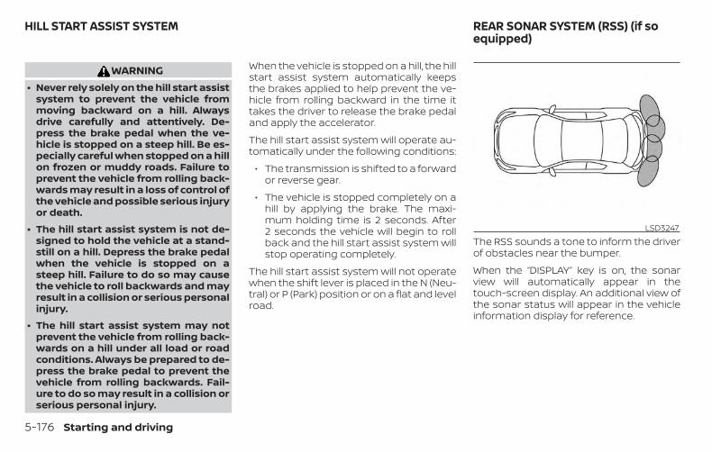
WARNING∙ Never rely solely on the hill start assist
system to prevent the vehicle frommoving backward on a hill. Alwaysdrive carefully and attentively. De-press the brake pedal when the ve-hicle is stopped on a steep hill. Be es-pecially careful when stopped on a hillon frozen or muddy roads. Failure toprevent the vehicle from rolling back-wards may result in a loss of control ofthe vehicle and possible serious injuryor death.
∙ The hill start assist system is not de-signed to hold the vehicle at a stand-still on a hill. Depress the brake pedalwhen the vehicle is stopped on asteep hill. Failure to do so may causethe vehicle to roll backwards and mayresult in a collision or serious personalinjury.
∙ The hill start assist system may notprevent the vehicle from rolling back-wards on a hill under all load or roadconditions. Always be prepared to de-press the brake pedal to prevent thevehicle from rolling backwards. Fail-ure to do so may result in a collision orserious personal injury.
When the vehicle is stopped on a hill, the hillstart assist system automatically keepsthe brakes applied to help prevent the ve-hicle from rolling backward in the time ittakes the driver to release the brake pedaland apply the accelerator.
The hill start assist system will operate au-tomatically under the following conditions:
∙ The transmission is shifted to a forwardor reverse gear.
∙ The vehicle is stopped completely on ahill by applying the brake. The maxi-mum holding time is 2 seconds. After2 seconds the vehicle will begin to rollback and the hill start assist system willstop operating completely.
The hill start assist system will not operatewhen the shift lever is placed in the N (Neu-tral) or P (Park) position or on a flat and levelroad.
The RSS sounds a tone to inform the driverof obstacles near the bumper.
When the “DISPLAY” key is on, the sonarview will automatically appear in thetouch-screen display. An additional view ofthe sonar status will appear in the vehicleinformation display for reference.
LSD3247
HILL START ASSIST SYSTEM REAR SONAR SYSTEM (RSS) (if soequipped)
5-176 Starting and driving
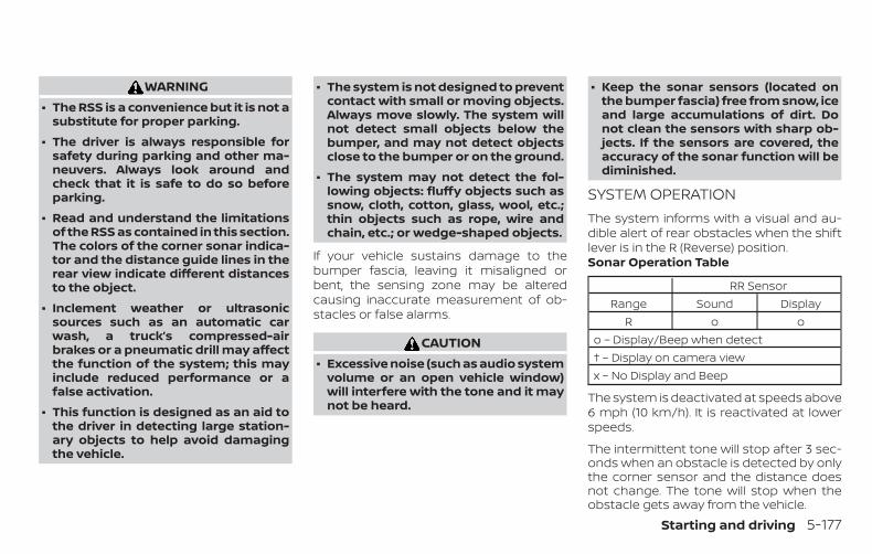
WARNING∙ The RSS is a convenience but it is not a
substitute for proper parking.
∙ The driver is always responsible forsafety during parking and other ma-neuvers. Always look around andcheck that it is safe to do so beforeparking.
∙ Read and understand the limitationsof the RSS as contained in this section.The colors of the corner sonar indica-tor and the distance guide lines in therear view indicate different distancesto the object.
∙ Inclement weather or ultrasonicsources such as an automatic carwash, a truck’s compressed-airbrakes or a pneumatic drill may affectthe function of the system; this mayinclude reduced performance or afalse activation.
∙ This function is designed as an aid tothe driver in detecting large station-ary objects to help avoid damagingthe vehicle.
∙ The system is not designed to preventcontact with small or moving objects.Always move slowly. The system willnot detect small objects below thebumper, and may not detect objectsclose to the bumper or on the ground.
∙ The system may not detect the fol-lowing objects: fluffy objects such assnow, cloth, cotton, glass, wool, etc.;thin objects such as rope, wire andchain, etc.; or wedge-shaped objects.
If your vehicle sustains damage to thebumper fascia, leaving it misaligned orbent, the sensing zone may be alteredcausing inaccurate measurement of ob-stacles or false alarms.
CAUTION∙ Excessive noise (such as audio system
volume or an open vehicle window)will interfere with the tone and it maynot be heard.
∙ Keep the sonar sensors (located onthe bumper fascia) free from snow, iceand large accumulations of dirt. Donot clean the sensors with sharp ob-jects. If the sensors are covered, theaccuracy of the sonar function will bediminished.
SYSTEM OPERATIONThe system informs with a visual and au-dible alert of rear obstacles when the shiftlever is in the R (Reverse) position.Sonar Operation Table
RR SensorRange Sound Display
R o oo – Display/Beep when detect† – Display on camera viewx – No Display and Beep
The system is deactivated at speeds above6 mph (10 km/h). It is reactivated at lowerspeeds.
The intermittent tone will stop after 3 sec-onds when an obstacle is detected by onlythe corner sensor and the distance doesnot change. The tone will stop when theobstacle gets away from the vehicle.
Starting and driving 5-177
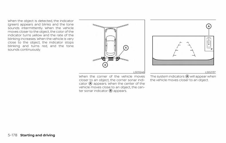
When the object is detected, the indicator(green) appears and blinks and the tonesounds intermittently. When the vehiclemoves closer to the object, the color of theindicator turns yellow and the rate of theblinking increases. When the vehicle is veryclose to the object, the indicator stopsblinking and turns red, and the tonesounds continuously.
When the corner of the vehicle movescloser to an object, the corner sonar indi-cator �A appears. When the center of thevehicle moves close to an object, the cen-ter sonar indicator �B appears.
The system indicators �A will appear whenthe vehicle moves closer to an object.
LSD3246 LSD2137
5-178 Starting and driving
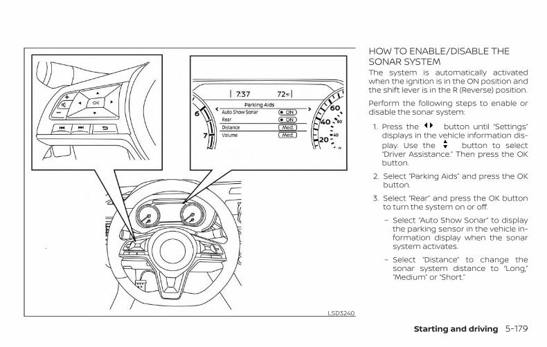
HOW TO ENABLE/DISABLE THESONAR SYSTEMThe system is automatically activatedwhen the ignition is in the ON position andthe shift lever is in the R (Reverse) position.
Perform the following steps to enable ordisable the sonar system:
1. Press the button until “Settings”displays in the vehicle information dis-play. Use the button to select“Driver Assistance.” Then press the OKbutton.
2. Select “Parking Aids” and press the OKbutton.
3. Select “Rear” and press the OK buttonto turn the system on or off.
– Select “Auto Show Sonar” to displaythe parking sensor in the vehicle in-formation display when the sonarsystem activates.
– Select “Distance” to change thesonar system distance to “Long,”“Medium” or “Short.”
LSD3240
Starting and driving 5-179
SONAR LIMITATIONS
WARNINGListed below are the system limitationsfor the sonar system. Failure to operatethe vehicle in accordance with thesesystem limitations could result in seri-ous injury or death.
∙ Read and understand the limitationsof the sonar system as contained inthis section. Inclement weather mayaffect the function of the sonar sys-tem; this may include reduced perfor-mance or a false activation.
∙ The system is deactivated at speedsabove 6 mph (10 km/h). It is reacti-vated at lower speeds.
∙ Inclement weather or ultrasonicsources such as an automatic carwash, a truck’s compressed-airbrakes or a pneumatic drill may affectthe function of the system; this mayinclude reduced performance or afalse activation.
∙ The system is not designed to preventcontact with small or moving objects.Always move slowly. The system willnot detect small objects below thebumper or on the ground.
∙ The system may not detect the fol-lowing objects: fluffy objects such assnow, cloth, cotton, glass-wool, etc.;thin objects such as rope, wire andchain, etc.; or wedge-shaped objects.
∙ The system may not detect objects atspeeds above 3 mph (5 km/h) andmay not detect certain angular ormoving objects.
SYSTEM TEMPORARILYUNAVAILABLEWhen sonar blockage is detected, the sys-tem will be deactivated automatically.
The system is not available until the condi-tions no longer exist.
The sonar sensors may be blocked by tem-porary ambient conditions such as splash-ing water, mist or fog. The blocked condi-tion may also be caused by objects such asice, frost or dirt obstructing the sonar sen-sors.
Action to take:
When the above conditions no longer exist,the system will resume automatically.
5-180 Starting and driving
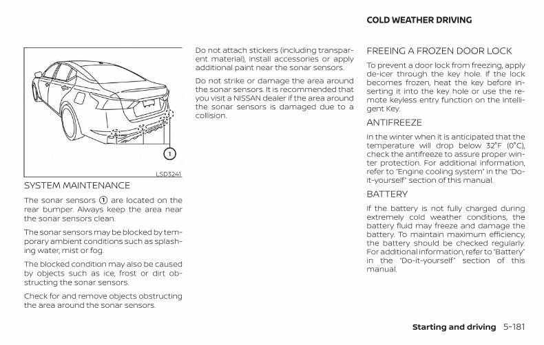
SYSTEM MAINTENANCEThe sonar sensors �1 are located on therear bumper. Always keep the area nearthe sonar sensors clean.
The sonar sensors may be blocked by tem-porary ambient conditions such as splash-ing water, mist or fog.
The blocked condition may also be causedby objects such as ice, frost or dirt ob-structing the sonar sensors.
Check for and remove objects obstructingthe area around the sonar sensors.
Do not attach stickers (including transpar-ent material), install accessories or applyadditional paint near the sonar sensors.
Do not strike or damage the area aroundthe sonar sensors. It is recommended thatyou visit a NISSAN dealer if the area aroundthe sonar sensors is damaged due to acollision.
FREEING A FROZEN DOOR LOCKTo prevent a door lock from freezing, applyde-icer through the key hole. If the lockbecomes frozen, heat the key before in-serting it into the key hole or use the re-mote keyless entry function on the Intelli-gent Key.
ANTIFREEZEIn the winter when it is anticipated that thetemperature will drop below 32°F (0°C),check the antifreeze to assure proper win-ter protection. For additional information,refer to “Engine cooling system” in the “Do-it-yourself ” section of this manual.
BATTERYIf the battery is not fully charged duringextremely cold weather conditions, thebattery fluid may freeze and damage thebattery. To maintain maximum efficiency,the battery should be checked regularly.For additional information, refer to “Battery”in the “Do-it-yourself ” section of thismanual.
LSD3241
COLD WEATHER DRIVING
Starting and driving 5-181
DRAINING OF COOLANT WATERIf the vehicle is to be left outside withoutantifreeze, drain the cooling system, includ-ing the engine block. Refill before operatingthe vehicle. For additional information, referto “Changing engine coolant” in the “Do-it-yourself ” section of this manual.
TIRE EQUIPMENT1. SUMMER tires have a tread designed to
provide superior performance on drypavement. However, the performanceof these tires will be substantially re-duced in snowy and icy conditions. Ifyou operate your vehicle on snowy oricy roads, NISSAN recommends the useof MUD & SNOW or ALL SEASON TIRESon all four wheels. It is recommendedthat you visit a NISSAN dealer for the tiretype, size, speed rating and availabilityinformation.
2. For additional traction on icy roads,studded tires may be used. However,some U.S. states and Canadian prov-inces prohibit their use. Check local,state and provincial laws before install-ing studded tires.
Skid and traction capabilities of studdedsnow tires on wet or dry surfaces may bepoorer than that of non-studded snowtires.
3. Tire chains may be used. For additionalinformation, refer to “Tire chains” in the“Do-it-yourself ” section of this manual.
SPECIAL WINTER EQUIPMENTIt is recommended that the following itemsbe carried in the vehicle during winter:
∙ A scraper and stiff-bristled brush to re-move ice and snow from the windowsand wiper blades.
∙ A sturdy, flat board to be placed underthe jack to give it firm support.
∙ A shovel to dig the vehicle out of snow-drifts.
∙ Extra washer fluid to refill thewindshield-washer fluid reservoir.
DRIVING ON SNOW OR ICE
WARNING∙ Wet ice (32°F, 0°C and freezing rain),
very cold snow or ice can be slick andvery hard to drive on. The vehicle willhave much less traction or “grip” un-der these conditions. Try to avoid driv-ing on wet ice until the road is saltedor sanded.
∙ Whatever the condition, drive withcaution. Accelerate and slow downwith care. If accelerating or down-shifting too fast, the drive wheels willlose even more traction.
∙ Allow more stopping distance underthese conditions. Braking should bestarted sooner than on dry pavement.
∙ Allow greater following distances onslippery roads.
∙ Watch for slippery spots (glare ice).These may appear on an otherwiseclear road in shaded areas. If a patchof ice is seen ahead, brake beforereaching it. Try not to brake while onthe ice, and avoid any sudden steeringmaneuvers.
5-182 Starting and driving
∙ Do not use the cruise control on slip-pery roads.
∙ Snow can trap dangerous exhaustgases under your vehicle. Keep snowclear of the exhaust pipe and fromaround your vehicle.
ENGINE BLOCK HEATER (if soequipped)Engine block heaters are used to assistwith cold temperature starting.
The engine block heater should be usedwhen the outside temperature is 20°F (-7°C)or lower.
WARNING∙ Do not use your engine block heater
with an ungrounded electrical systemor a 2-pronged adapter. You can beseriously injured by an electricalshock if you use an ungroundedconnection.
∙ Disconnect and properly store the en-gine block heater cord before startingthe engine. Damage to the cord couldresult in an electrical shock and cancause serious injury.
∙ Use a heavy-duty 3-wire, 3-prongedextension cord rated for at least 10 A.Plug the extension cord into a GroundFault Interrupt (GFI) protected,grounded 110-VAC outlet. Failure touse the proper extension cord or agrounded outlet can result in a fire orelectrical shock and cause seriouspersonal injury.
To use the engine block heater:
1. Turn the engine off.
2. Open the hood and unwrap the engineblock heater cord.
3. Plug the engine block heater cord intoa grounded 3-wire, 3-pronged exten-sion cord.
4. Plug the extension cord into a GroundFault Interrupt (GFI) protected,grounded 110-volt AC (VAC) outlet.
5. The engine block heater must beplugged in for at least 2–4 hours, de-pending on outside temperatures, toproperly warm the engine coolant. Usean appropriate timer to turn the engineblock heater on.
6. Before starting the engine, unplug andproperly store the cord to keep it awayfrom moving parts.
Starting and driving 5-183
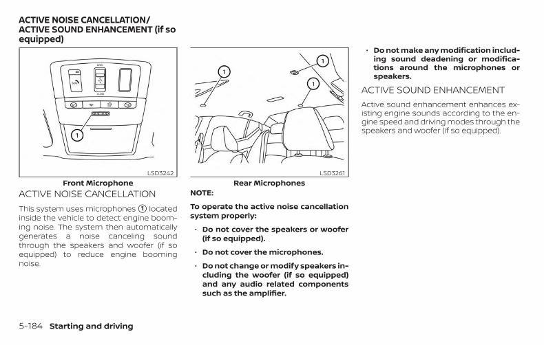
ACTIVE NOISE CANCELLATIONThis system uses microphones �1 locatedinside the vehicle to detect engine boom-ing noise. The system then automaticallygenerates a noise canceling soundthrough the speakers and woofer (if soequipped) to reduce engine boomingnoise.
NOTE:
To operate the active noise cancellationsystem properly:
∙ Do not cover the speakers or woofer(if so equipped).
∙ Do not cover the microphones.
∙ Do not change or modify speakers in-cluding the woofer (if so equipped)and any audio related componentssuch as the amplifier.
∙ Do not make any modification includ-ing sound deadening or modifica-tions around the microphones orspeakers.
ACTIVE SOUND ENHANCEMENTActive sound enhancement enhances ex-isting engine sounds according to the en-gine speed and driving modes through thespeakers and woofer (if so equipped).
Front MicrophoneLSD3242
Rear MicrophonesLSD3261
ACTIVE NOISE CANCELLATION/ACTIVE SOUND ENHANCEMENT (if soequipped)
5-184 Starting and driving
6 In case of emergency
Hazard warning flasher switch . . . . . . . . . . . . . . . . . . 6-2Emergency engine shut off . . . . . . . . . . . . . . . . . . . . . . 6-2Flat tire . . . . . . . . . . . . . . . . . . . . . . . . . . . . . . . . . . . . . . . . . . 6-3
Tire Pressure Monitoring System(TPMS). . . . . . . . . . . . . . . . . . . . . . . . . . . . . . . . . . . . . . . . 6-3Changing a flat tire . . . . . . . . . . . . . . . . . . . . . . . . . . . 6-4
Jump starting . . . . . . . . . . . . . . . . . . . . . . . . . . . . . . . . . . . 6-9
Push starting . . . . . . . . . . . . . . . . . . . . . . . . . . . . . . . . . . . .6-11If your vehicle overheats . . . . . . . . . . . . . . . . . . . . . . . . .6-11Towing your vehicle . . . . . . . . . . . . . . . . . . . . . . . . . . . . 6-12
Towing recommended by NISSAN . . . . . . . . . . . 6-12Vehicle recovery (freeing a stuckvehicle) . . . . . . . . . . . . . . . . . . . . . . . . . . . . . . . . . . . . . . 6-14
Push the switch on to warn other driverswhen you must stop or park under emer-gency conditions. All turn signal lights flash.
WARNING∙ If stopping for an emergency, be sure
to move the vehicle well off the road.
∙ Do not use the hazard warning flash-ers while moving on the highway un-less unusual circumstances force youto drive so slowly that your vehiclemight become a hazard to othertraffic.
∙ Turn signals do not work when thehazard warning flasher lights are on.
The flashers will operate with the ignitionswitch placed in any position.
Some jurisdictions may prohibit the useof the hazard warning flasher switchwhile driving.
To shut off the engine in an emergencysituation while driving, perform the follow-ing procedure:
– Rapidly push the push-button ignitionswitch three consecutive times in lessthan 1.5 seconds, or
– Push and hold the push-button ignitionswitch for more than 2 seconds.
LIC0394
HAZARD WARNING FLASHER SWITCH EMERGENCY ENGINE SHUT OFF
6-2 In case of emergency
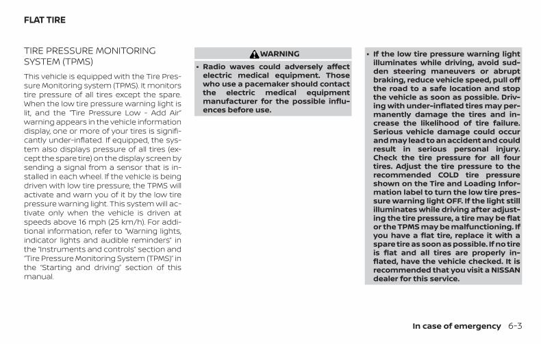
TIRE PRESSURE MONITORINGSYSTEM (TPMS)This vehicle is equipped with the Tire Pres-sure Monitoring system (TPMS). It monitorstire pressure of all tires except the spare.When the low tire pressure warning light islit, and the “Tire Pressure Low - Add Air”warning appears in the vehicle informationdisplay, one or more of your tires is signifi-cantly under-inflated. If equipped, the sys-tem also displays pressure of all tires (ex-cept the spare tire) on the display screen bysending a signal from a sensor that is in-stalled in each wheel. If the vehicle is beingdriven with low tire pressure, the TPMS willactivate and warn you of it by the low tirepressure warning light. This system will ac-tivate only when the vehicle is driven atspeeds above 16 mph (25 km/h). For addi-tional information, refer to “Warning lights,indicator lights and audible reminders” inthe “Instruments and controls” section and“Tire Pressure Monitoring System (TPMS)” inthe “Starting and driving” section of thismanual.
WARNING∙ Radio waves could adversely affect
electric medical equipment. Thosewho use a pacemaker should contactthe electric medical equipmentmanufacturer for the possible influ-ences before use.
∙ If the low tire pressure warning lightilluminates while driving, avoid sud-den steering maneuvers or abruptbraking, reduce vehicle speed, pull offthe road to a safe location and stopthe vehicle as soon as possible. Driv-ing with under-inflated tires may per-manently damage the tires and in-crease the likelihood of tire failure.Serious vehicle damage could occurand may lead to an accident and couldresult in serious personal injury.Check the tire pressure for all fourtires. Adjust the tire pressure to therecommended COLD tire pressureshown on the Tire and Loading Infor-mation label to turn the low tire pres-sure warning light OFF. If the light stillilluminates while driving after adjust-ing the tire pressure, a tire may be flator the TPMS may be malfunctioning. Ifyou have a flat tire, replace it with aspare tire as soon as possible. If no tireis flat and all tires are properly in-flated, have the vehicle checked. It isrecommended that you visit a NISSANdealer for this service.
FLAT TIRE
In case of emergency 6-3
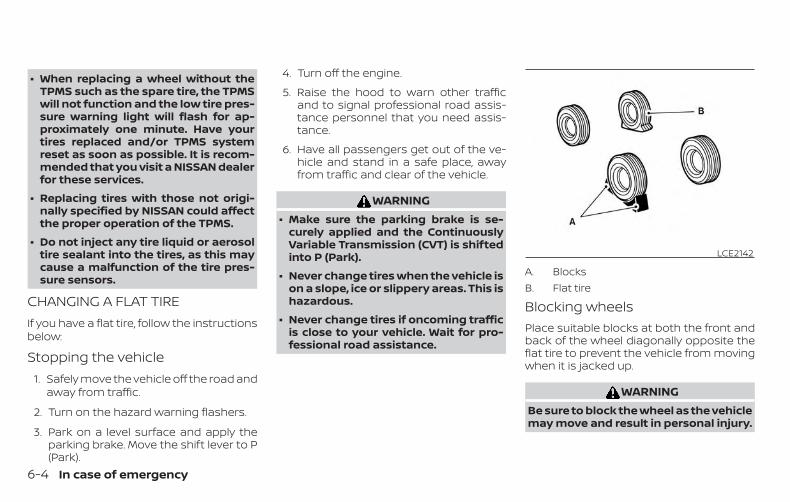
∙ When replacing a wheel without theTPMS such as the spare tire, the TPMSwill not function and the low tire pres-sure warning light will flash for ap-proximately one minute. Have yourtires replaced and/or TPMS systemreset as soon as possible. It is recom-mended that you visit a NISSAN dealerfor these services.
∙ Replacing tires with those not origi-nally specified by NISSAN could affectthe proper operation of the TPMS.
∙ Do not inject any tire liquid or aerosoltire sealant into the tires, as this maycause a malfunction of the tire pres-sure sensors.
CHANGING A FLAT TIREIf you have a flat tire, follow the instructionsbelow:
Stopping the vehicle1. Safely move the vehicle off the road and
away from traffic.
2. Turn on the hazard warning flashers.
3. Park on a level surface and apply theparking brake. Move the shift lever to P(Park).
4. Turn off the engine.
5. Raise the hood to warn other trafficand to signal professional road assis-tance personnel that you need assis-tance.
6. Have all passengers get out of the ve-hicle and stand in a safe place, awayfrom traffic and clear of the vehicle.
WARNING∙ Make sure the parking brake is se-
curely applied and the ContinuouslyVariable Transmission (CVT) is shiftedinto P (Park).
∙ Never change tires when the vehicle ison a slope, ice or slippery areas. This ishazardous.
∙ Never change tires if oncoming trafficis close to your vehicle. Wait for pro-fessional road assistance.
A. BlocksB. Flat tire
Blocking wheelsPlace suitable blocks at both the front andback of the wheel diagonally opposite theflat tire to prevent the vehicle from movingwhen it is jacked up.
WARNINGBe sure to block the wheel as the vehiclemay move and result in personal injury.
LCE2142
6-4 In case of emergency
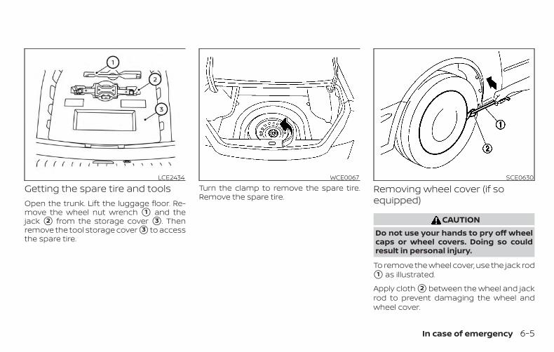
Getting the spare tire and toolsOpen the trunk. Lift the luggage floor. Re-move the wheel nut wrench �1 and thejack �2 from the storage cover �3 . Thenremove the tool storage cover �3 to accessthe spare tire.
Turn the clamp to remove the spare tire.Remove the spare tire.
Removing wheel cover (if soequipped)
CAUTIONDo not use your hands to pry off wheelcaps or wheel covers. Doing so couldresult in personal injury.
To remove the wheel cover, use the jack rod�1 as illustrated.
Apply cloth �2 between the wheel and jackrod to prevent damaging the wheel andwheel cover.
LCE2434 WCE0067 SCE0630
In case of emergency 6-5
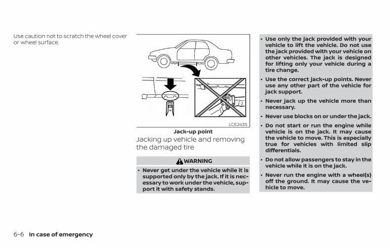
Use caution not to scratch the wheel coveror wheel surface.
Jacking up vehicle and removingthe damaged tire
WARNING∙ Never get under the vehicle while it is
supported only by the jack. If it is nec-essary to work under the vehicle, sup-port it with safety stands.
∙ Use only the jack provided with yourvehicle to lift the vehicle. Do not usethe jack provided with your vehicle onother vehicles. The jack is designedfor lifting only your vehicle during atire change.
∙ Use the correct jack-up points. Neveruse any other part of the vehicle forjack support.
∙ Never jack up the vehicle more thannecessary.
∙ Never use blocks on or under the jack.
∙ Do not start or run the engine whilevehicle is on the jack. It may causethe vehicle to move. This is especiallytrue for vehicles with limited slipdifferentials.
∙ Do not allow passengers to stay in thevehicle while it is on the jack.
∙ Never run the engine with a wheel(s)off the ground. It may cause the ve-hicle to move.
Jack-up pointLCE2435
6-6 In case of emergency
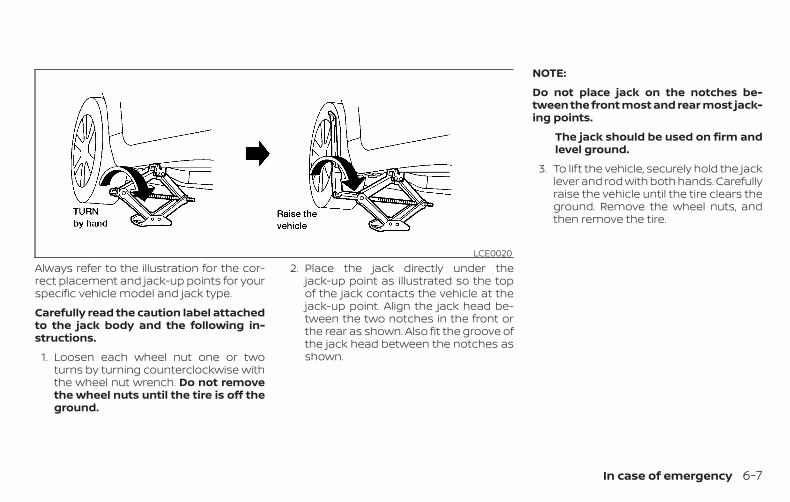
Always refer to the illustration for the cor-rect placement and jack-up points for yourspecific vehicle model and jack type.
Carefully read the caution label attachedto the jack body and the following in-structions.
1. Loosen each wheel nut one or twoturns by turning counterclockwise withthe wheel nut wrench. Do not removethe wheel nuts until the tire is off theground.
2. Place the jack directly under thejack-up point as illustrated so the topof the jack contacts the vehicle at thejack-up point. Align the jack head be-tween the two notches in the front orthe rear as shown. Also fit the groove ofthe jack head between the notches asshown.
NOTE:
Do not place jack on the notches be-tween the front most and rear most jack-ing points.
The jack should be used on firm andlevel ground.
3. To lift the vehicle, securely hold the jacklever and rod with both hands. Carefullyraise the vehicle until the tire clears theground. Remove the wheel nuts, andthen remove the tire.
LCE0020
In case of emergency 6-7
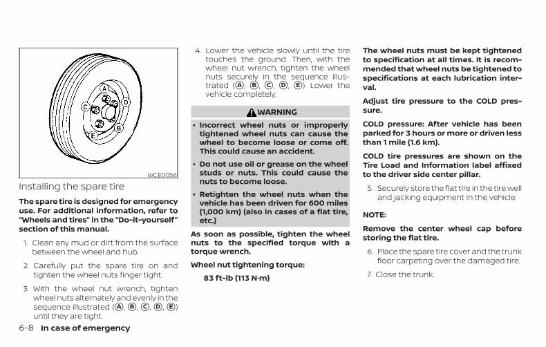
Installing the spare tireThe spare tire is designed for emergencyuse. For additional information, refer to“Wheels and tires” in the “Do-it-yourself”section of this manual.
1. Clean any mud or dirt from the surfacebetween the wheel and hub.
2. Carefully put the spare tire on andtighten the wheel nuts finger tight.
3. With the wheel nut wrench, tightenwheel nuts alternately and evenly in thesequence illustrated (�A , �B , �C , �D , �E )until they are tight.
4. Lower the vehicle slowly until the tiretouches the ground. Then, with thewheel nut wrench, tighten the wheelnuts securely in the sequence illus-trated (�A , �B , �C , �D , �E ). Lower thevehicle completely.
WARNING∙ Incorrect wheel nuts or improperly
tightened wheel nuts can cause thewheel to become loose or come off.This could cause an accident.
∙ Do not use oil or grease on the wheelstuds or nuts. This could cause thenuts to become loose.
∙ Retighten the wheel nuts when thevehicle has been driven for 600 miles(1,000 km) (also in cases of a flat tire,etc.)
As soon as possible, tighten the wheelnuts to the specified torque with atorque wrench.
Wheel nut tightening torque:
83 ft-lb (113 N·m)
The wheel nuts must be kept tightenedto specification at all times. It is recom-mended that wheel nuts be tightened tospecifications at each lubrication inter-val.
Adjust tire pressure to the COLD pres-sure.
COLD pressure: After vehicle has beenparked for 3 hours or more or driven lessthan 1 mile (1.6 km).
COLD tire pressures are shown on theTire Load and Information label affixedto the driver side center pillar.
5. Securely store the flat tire in the tire welland jacking equipment in the vehicle.
NOTE:
Remove the center wheel cap beforestoring the flat tire.
6. Place the spare tire cover and the trunkfloor carpeting over the damaged tire.
7. Close the trunk.
WCE0056
6-8 In case of emergency
WARNING∙ Always make sure that the spare tire
and jacking equipment are properlysecured after use. Such items can be-come dangerous projectiles in an ac-cident or sudden stop.
∙ The spare tire is designed for emer-gency use. For additional information,refer to “Wheels and tires” in the “Do-it-yourself” section of this manual.
To start your engine with a booster battery,the instructions and precautions belowmust be followed.
WARNING∙ If done incorrectly, jump starting can
lead to a battery explosion, resultingin severe injury or death. It could alsodamage your vehicle.
∙ Explosive hydrogen gas is alwayspresent in the vicinity of the battery.Keep all sparks and flames away fromthe battery.
∙ Do not allow battery fluid to come intocontact with eyes, skin, clothing orpainted surfaces. Battery fluid is acorrosive sulfuric acid solution whichcan cause severe burns. If the fluidshould come into contact with any-thing, immediately flush the con-tacted area with water.
∙ Keep battery out of the reach ofchildren.
∙ The booster battery must be rated at12 volts. Use of an improperly ratedbattery can damage your vehicle.
∙ Whenever working on or near a bat-tery, always wear suitable eye protec-tors (for example, goggles or indus-trial safety spectacles) and removerings, metal bands, or any other jew-elry. Do not lean over the batterywhen jump starting.
∙ Do not attempt to jump start a frozenbattery. It could explode and causeserious injury.
∙ Your vehicle has an automatic enginecooling fan. It could come on at anytime. Keep hands and other objectsaway from it.
JUMP STARTING
In case of emergency 6-9
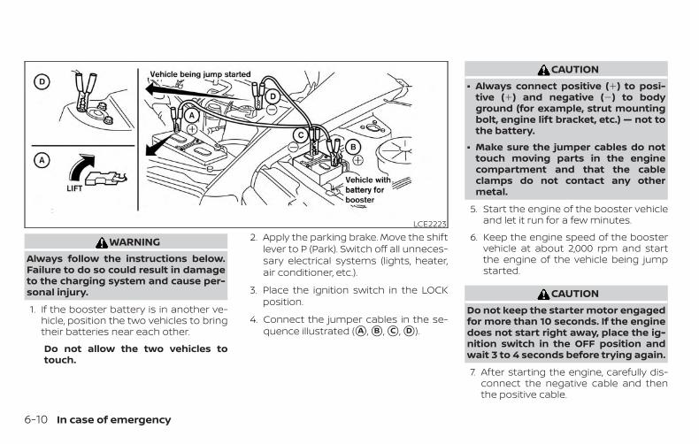
WARNINGAlways follow the instructions below.Failure to do so could result in damageto the charging system and cause per-sonal injury.
1. If the booster battery is in another ve-hicle, position the two vehicles to bringtheir batteries near each other.
Do not allow the two vehicles totouch.
2. Apply the parking brake. Move the shiftlever to P (Park). Switch off all unneces-sary electrical systems (lights, heater,air conditioner, etc.).
3. Place the ignition switch in the LOCKposition.
4. Connect the jumper cables in the se-quence illustrated (�A , �B , �C , �D ).
CAUTION∙ Always connect positive (�) to posi-
tive (�) and negative (�) to bodyground (for example, strut mountingbolt, engine lift bracket, etc.) — not tothe battery.
∙ Make sure the jumper cables do nottouch moving parts in the enginecompartment and that the cableclamps do not contact any othermetal.
5. Start the engine of the booster vehicleand let it run for a few minutes.
6. Keep the engine speed of the boostervehicle at about 2,000 rpm and startthe engine of the vehicle being jumpstarted.
CAUTIONDo not keep the starter motor engagedfor more than 10 seconds. If the enginedoes not start right away, place the ig-nition switch in the OFF position andwait 3 to 4 seconds before trying again.
7. After starting the engine, carefully dis-connect the negative cable and thenthe positive cable.
LCE2223
6-10 In case of emergency
CAUTION∙ Do not push start this vehicle. The
three-way catalyst may be damaged.
∙ Continuously Variable Transmission(CVT) models cannot be push-startedor tow-started. Attempting to do somay cause transmission damage.
If your vehicle is overheating (indicated byan extremely high temperature gaugereading), or if you feel a lack of enginepower, detect abnormal noise, etc. take thefollowing steps.
WARNING∙ Do not continue to drive if your vehicle
overheats. Doing so could cause en-gine damage or a vehicle fire.
∙ To avoid the danger of being scalded,never remove the radiator cap whilethe engine is still hot. When the radia-tor cap is removed, pressurized hotwater will spurt out, possibly causingserious injury.
∙ Do not open the hood if steam is com-ing out.
1. Move the vehicle safely off the road, ap-ply the parking brake and move theshift lever to P (Park).
Do not stop the engine.
2. Turn off the air conditioner. Open all thewindows, move the heater or air condi-tioner temperature control to maximumhot and fan control to high speed.
3. Get out of the vehicle. Look and listenfor steam or coolant escaping from theradiator before opening the hood. (Ifsteam or coolant is escaping, turn offthe engine.) Do not open the hood fur-ther until no steam or coolant can beseen.
4. Open the engine hood.
WARNINGIf steam or water is coming from theengine, stand clear to prevent gettingburned.
5. Visually check drive belts for damageor looseness. Also check if the coolingfan is running. The radiator hoses andradiator should not leak water. If cool-ant is leaking, the water pump belt ismissing or loose, or the cooling fandoes not run, stop the engine.
WARNINGBe careful not to allow your hands, hair,jewelry or clothing to come into contactwith, or get caught in, engine belts orthe engine cooling fan. The engine cool-ing fan can start at any time.
PUSH STARTING IF YOUR VEHICLE OVERHEATS
In case of emergency 6-11
6. After the engine cools down, check thecoolant level in the engine coolant res-ervoir tank with the engine running.Add coolant to the engine coolant res-ervoir tank if necessary. It is recom-mended that you visit a NISSAN dealerfor this service.
When towing your vehicle, all State (Provin-cial in Canada) and local regulations fortowing must be followed. Incorrect towingequipment could damage your vehicle.Towing instructions are available from aNISSAN dealer. Local service operators aregenerally familiar with the applicable lawsand procedures for towing. To assureproper towing and to prevent accidentaldamage to your vehicle, NISSAN recom-mends having a service operator tow yourvehicle. It is advisable to have the serviceoperator carefully read the following pre-cautions:
WARNING∙ Never ride in a vehicle that is being
towed.
∙ Never get under your vehicle after ithas been lifted by a tow truck.
CAUTION∙ When towing, make sure that the
transmission, axles, steering systemand powertrain are in working condi-tion. If any of these conditions apply,dollies or a flatbed tow truck must beused.
∙ Always attach safety chains beforetowing.
For additional information, refer to “Flattowing” in the “Technical and consumer in-formation” section of this manual.
TOWING RECOMMENDED BYNISSANNISSAN recommends towing your vehiclebased upon the type of drivetrain. For addi-tional information, refer to the diagrams inthis section to ensure that your vehicle isproperly towed.
TOWING YOUR VEHICLE
6-12 In case of emergency
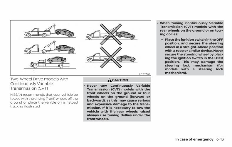
Two-Wheel Drive models withContinuously VariableTransmission (CVT)NISSAN recommends that your vehicle betowed with the driving (front) wheels off theground or place the vehicle on a flatbedtruck as illustrated.
CAUTION∙ Never tow Continuously Variable
Transmission (CVT) models with thefront wheels on the ground or fourwheels on the ground (forward orbackward), as this may cause seriousand expensive damage to the trans-mission. If it is necessary to tow thevehicle with the rear wheels raisedalways use towing dollies under thefront wheels.
∙ When towing Continuously VariableTransmission (CVT) models with therear wheels on the ground or on tow-ing dollies:
– Place the ignition switch in the OFFposition, and secure the steeringwheel in a straight-ahead positionwith a rope or similar device. Neversecure the steering wheel by plac-ing the ignition switch in the LOCKposition. This may damage thesteering lock mechanism (formodels with a steering lockmechanism).LCE2369
In case of emergency 6-13
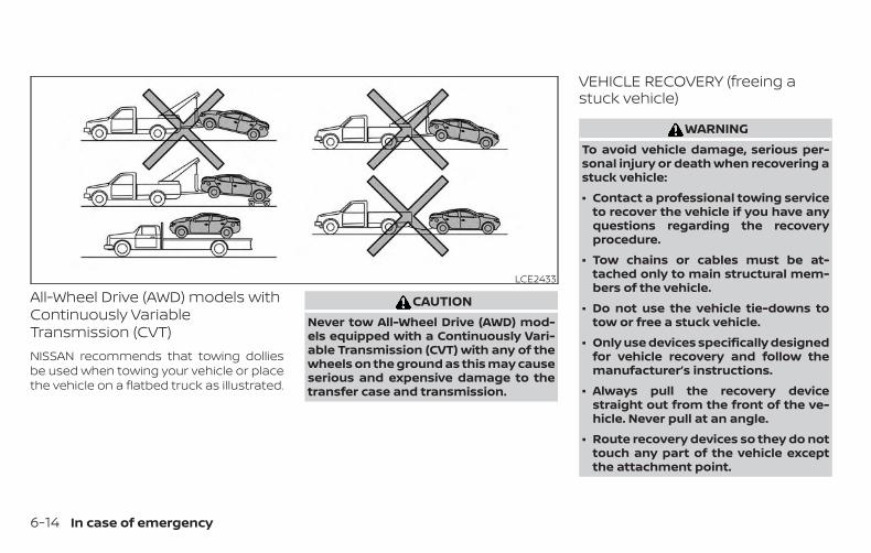
All-Wheel Drive (AWD) models withContinuously VariableTransmission (CVT)NISSAN recommends that towing dolliesbe used when towing your vehicle or placethe vehicle on a flatbed truck as illustrated.
CAUTIONNever tow All-Wheel Drive (AWD) mod-els equipped with a Continuously Vari-able Transmission (CVT) with any of thewheels on the ground as this may causeserious and expensive damage to thetransfer case and transmission.
VEHICLE RECOVERY (freeing astuck vehicle)
WARNINGTo avoid vehicle damage, serious per-sonal injury or death when recovering astuck vehicle:
∙ Contact a professional towing serviceto recover the vehicle if you have anyquestions regarding the recoveryprocedure.
∙ Tow chains or cables must be at-tached only to main structural mem-bers of the vehicle.
∙ Do not use the vehicle tie-downs totow or free a stuck vehicle.
∙ Only use devices specifically designedfor vehicle recovery and follow themanufacturer’s instructions.
∙ Always pull the recovery devicestraight out from the front of the ve-hicle. Never pull at an angle.
∙ Route recovery devices so they do nottouch any part of the vehicle exceptthe attachment point.
LCE2433
6-14 In case of emergency
If your vehicle is stuck in sand, snow, mud,etc., use a tow strap or other device de-signed specifically for vehicle recovery. Al-ways follow the manufacturer’s instruc-tions for the recovery device.
Rocking a stuck vehicle
WARNING∙ Stand clear of a stuck vehicle.
∙ Do not spin your tires at high speed.This could cause them to explode andresult in serious injury. Parts of yourvehicle could also overheat and bedamaged.
If your vehicle is stuck in sand, snow, mud,etc., use the following procedure:
1. Turn off the Vehicle Dynamic Control(VDC) system.
2. Make sure the area in front and behindthe vehicle is clear of obstructions.
3. Turn the steering wheel right and left toclear an area around the front tires.
4. Slowly rock the vehicle forward andbackward.
∙ Shift back and forth between R (Re-verse) and D (Drive).
∙ Apply the accelerator as little as pos-sible to maintain the rocking motion.
∙ Release the accelerator pedal beforeshifting between R (Reverse) and D(Drive).
∙ Do not spin the tires above 35 mph(55 km/h).
5. If the vehicle cannot be freed after afew tries, contact a professional towingservice to remove the vehicle.
In case of emergency 6-15

MEMO
6-16 In case of emergency
7 Appearance and care
Cleaning exterior . . . . . . . . . . . . . . . . . . . . . . . . . . . . . . . . 7-2Washing. . . . . . . . . . . . . . . . . . . . . . . . . . . . . . . . . . . . . . 7-2Waxing . . . . . . . . . . . . . . . . . . . . . . . . . . . . . . . . . . . . . . . 7-2Removing spots . . . . . . . . . . . . . . . . . . . . . . . . . . . . . . 7-3Underbody . . . . . . . . . . . . . . . . . . . . . . . . . . . . . . . . . . . 7-3Glass . . . . . . . . . . . . . . . . . . . . . . . . . . . . . . . . . . . . . . . . . 7-3Aluminum alloy wheels (if so equipped) . . . . . . . 7-4Chrome parts . . . . . . . . . . . . . . . . . . . . . . . . . . . . . . . . 7-4Tire dressings . . . . . . . . . . . . . . . . . . . . . . . . . . . . . . . . 7-4
Cleaning interior. . . . . . . . . . . . . . . . . . . . . . . . . . . . . . . . . 7-4
Air fresheners . . . . . . . . . . . . . . . . . . . . . . . . . . . . . . . . 7-5Power moonroof (if so equipped) . . . . . . . . . . . . . 7-5Floor mats (if so equipped) . . . . . . . . . . . . . . . . . . . 7-6Seat belts . . . . . . . . . . . . . . . . . . . . . . . . . . . . . . . . . . . . 7-7
Corrosion protection . . . . . . . . . . . . . . . . . . . . . . . . . . . . 7-7Most common factors contributing tovehicle corrosion . . . . . . . . . . . . . . . . . . . . . . . . . . . . . 7-7Environmental factors influence therate of corrosion. . . . . . . . . . . . . . . . . . . . . . . . . . . . . . 7-7Protect your vehicle from corrosion . . . . . . . . . . 7-8
In order to maintain the appearance ofyour vehicle, it is important to take propercare of it.
To protect the paint surfaces, wash yourvehicle as soon as you can:
∙ After a rainfall to prevent possible dam-age from acid rain.
∙ After driving on coastal roads.
∙ When contaminants such as soot, birddroppings, tree sap, metal particles orbugs get on the paint surface.
∙ When dust or mud builds up on the sur-face.
Whenever possible, store or park your ve-hicle inside a garage or in a covered area.
When it is necessary to park outside, park ina shady area or protect the vehicle with abody cover.
Be careful not to scratch the paint sur-face when putting on or removing thebody cover.
WASHINGWash dirt off with a wet sponge and plentyof water. Clean the vehicle thoroughly us-ing a mild soap, a special vehicle soap orgeneral purpose dishwashing liquid mixedwith clean, lukewarm (never hot) water.
CAUTION∙ Do not use car washes that use acid in
the detergent. Some car washes, es-pecially brushless ones, use someacid for cleaning. The acid may reactwith some plastic vehicle compo-nents, causing them to crack. Thiscould affect their appearance, andalso could cause them not to functionproperly. Always check with your carwash to confirm that acid is not used.
∙ Do not wash the vehicle with stronghousehold soap, strong chemical de-tergents, gasoline or solvents.
∙ Do not wash the vehicle in direct sun-light or while the vehicle body is hot,as the surface may become water-spotted.
∙ Avoid using tight-napped or roughcloths, such as washing mitts. Caremust be taken when removingcaked-on dirt or other foreign sub-stances so the paint surface is notscratched or damaged.
Rinse the vehicle thoroughly with plenty ofclean water.
Inside edges, seams and folds on thedoors, hatches and hood are particularlyvulnerable to the effects of road salt. There-fore, these areas must be cleaned regularly.Take care that the drain holes in the loweredge of the door are open. Spray waterunder the body and in the wheel wells toloosen the dirt and wash away road salt.
A damp chamois can be used to dry thevehicle to avoid water spots.
WAXINGRegular waxing protects the paint surfaceand helps retain new vehicle appearance.Polishing is recommended to removebuilt-up wax residue and to avoid a weath-ered appearance before re-applying wax.
It is recommended that you visit a NISSANdealer to assist you in choosing the properproduct.
CLEANING EXTERIOR
7-2 Appearance and care
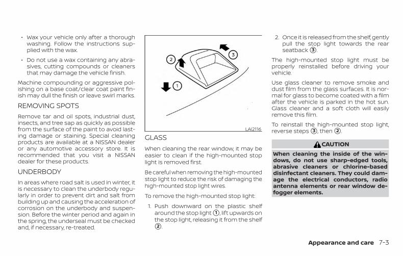
∙ Wax your vehicle only after a thoroughwashing. Follow the instructions sup-plied with the wax.
∙ Do not use a wax containing any abra-sives, cutting compounds or cleanersthat may damage the vehicle finish.
Machine compounding or aggressive pol-ishing on a base coat/clear coat paint fin-ish may dull the finish or leave swirl marks.
REMOVING SPOTSRemove tar and oil spots, industrial dust,insects, and tree sap as quickly as possiblefrom the surface of the paint to avoid last-ing damage or staining. Special cleaningproducts are available at a NISSAN dealeror any automotive accessory store. It isrecommended that you visit a NISSANdealer for these products.
UNDERBODYIn areas where road salt is used in winter, itis necessary to clean the underbody regu-larly in order to prevent dirt and salt frombuilding up and causing the acceleration ofcorrosion on the underbody and suspen-sion. Before the winter period and again inthe spring, the underseal must be checkedand, if necessary, re-treated.
GLASSWhen cleaning the rear window, it may beeasier to clean if the high-mounted stoplight is removed first.
Be careful when removing the high-mountedstop light to reduce the risk of damaging thehigh-mounted stop light wires.
To remove the high-mounted stop light:
1. Push downward on the plastic shelfaround the stop light �1 , lift upwards onthe stop light, releasing it from the shelf�2 .
2. Once it is released from the shelf, gentlypull the stop light towards the rearseatback �3 .
The high-mounted stop light must beproperly reinstalled before driving yourvehicle.
Use glass cleaner to remove smoke anddust film from the glass surfaces. It is nor-mal for glass to become coated with a filmafter the vehicle is parked in the hot sun.Glass cleaner and a soft cloth will easilyremove this film.
To reinstall the high-mounted stop light,reverse steps �3 , then �2 .
CAUTIONWhen cleaning the inside of the win-dows, do not use sharp-edged tools,abrasive cleaners or chlorine-baseddisinfectant cleaners. They could dam-age the electrical conductors, radioantenna elements or rear window de-fogger elements.
LAI2116
Appearance and care 7-3
ALUMINUM ALLOY WHEELS (if soequipped)Wash the wheels regularly with a spongedampened in a mild soap solution, espe-cially during winter months in areas whereroad salt is used. If not removed, road saltcan discolor the wheels.
CAUTIONFollow the directions below to avoidstaining or discoloring the wheels:
∙ Do not use a cleaner that uses strongacid or alkali contents to clean thewheels.
∙ Do not apply wheel cleaners to thewheels when they are hot. The wheeltemperature should be the same asambient temperature.
∙ Rinse the wheel to completely removethe cleaner within 15 minutes afterthe cleaner is applied.
CHROME PARTSClean all chrome parts regularly with anon-abrasive chrome polish to maintainthe finish.
TIRE DRESSINGSNISSAN does not recommend the use oftire dressings. Tire manufacturers apply acoating to the tires to help reduce discolor-ation of the rubber. If a tire dressing is ap-plied to the tires, it may react with the coat-ing and form a compound. This compoundmay come off the tire while driving andstain the vehicle paint.
If you choose to use a tire dressing, take thefollowing precautions:
∙ Use a water-based tire dressing. Thecoating on the tire dissolves more easilythan with an oil-based tire dressing.
∙ Apply a light coat of tire dressing to helpprevent it from entering the tiretread/grooves (where it would be diffi-cult to remove).
∙ Wipe off excess tire dressing using a drytowel. Make sure the tire dressing iscompletely removed from the tiretread/grooves.
∙ Allow the tire dressing to dry as recom-mended by the tire dressing manufac-turer.
Occasionally remove loose dust from theinterior trim, plastic parts and seats using avacuum cleaner or soft bristled brush. Wipethe vinyl and leather (if so equipped) sur-faces with a clean, soft cloth dampened inmild soap solution, then wipe clean with adry, soft cloth.
Regular care and cleaning is required inorder to maintain the appearance of theleather (if so equipped).
Before using any fabric protector, read themanufacturer’s recommendations. Somefabric protectors contain chemicals thatmay stain or bleach the seat material.
Use a cloth dampened only with water toclean the meter and gauge lens.
WARNINGDo not use water or acidic cleaners (hotsteam cleaners) on the seat. This candamage the seat or occupant classifi-cation sensor. This can also affect theoperation of the air bag system and re-sult in serious personal injury.
CLEANING INTERIOR
7-4 Appearance and care
CAUTION∙ Never use benzine, thinner or any
similar material.
∙ Small dirt particles can be abrasiveand damaging to leather surfacesand should be removed promptly. Donot use saddle soap, car waxes, pol-ishes, oils, cleaning fluids, solvents,detergents or ammonia-based clean-ers as they may damage the leather’snatural finish.
∙ Never use fabric protectors unlessrecommended by the manufacturer.
∙ Do not use glass or plastic cleaner onmeter or gauge lens covers. It maydamage the lens cover.
AIR FRESHENERSMost air fresheners use a solvent that couldaffect the vehicle interior. If you use an airfreshener, take the following precautions:
∙ Hanging-type air fresheners can causepermanent discoloration when theycontact vehicle interior surfaces. Placethe air freshener in a location that al-lows it to hang free and not contact aninterior surface.
∙ Liquid-type air fresheners typically clipon the vents. These products can causeimmediate damage and discolorationwhen spilled on interior surfaces.
Carefully read and follow the manufactur-er’s instructions before using the air fresh-eners.
POWER MOONROOF (if soequipped)The sunshade is made from a tricot mate-rial.
CAUTIONTo help prevent damaging the moon-roof while cleaning:
∙ Do not rub the material with a cloth.Doing so can damage the surface ofthe material or cause a stain tospread.
∙ Never use benzine, thinner or anysimilar chemical to clean the sun-shade. This may discolor the moon-roof and damage the surface.
∙ Clean water based stains by pattingthe surface with a clean soft clothdampened in warm water. Press aclean dry cloth onto the surface to re-move as much dampness as possibleand then let air dry.
∙ Clean oil based stains by patting thesurface with a clean soft cloth damp-ened in warm water. Press a clean drycloth onto the surface to remove asmuch dampness as possible and thenlet air dry.
Appearance and care 7-5
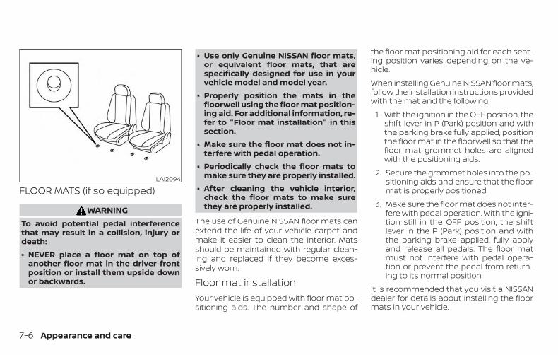
FLOOR MATS (if so equipped)
WARNINGTo avoid potential pedal interferencethat may result in a collision, injury ordeath:
∙ NEVER place a floor mat on top ofanother floor mat in the driver frontposition or install them upside downor backwards.
∙ Use only Genuine NISSAN floor mats,or equivalent floor mats, that arespecifically designed for use in yourvehicle model and model year.
∙ Properly position the mats in thefloorwell using the floor mat position-ing aid. For additional information, re-fer to "Floor mat installation" in thissection.
∙ Make sure the floor mat does not in-terfere with pedal operation.
∙ Periodically check the floor mats tomake sure they are properly installed.
∙ After cleaning the vehicle interior,check the floor mats to make surethey are properly installed.
The use of Genuine NISSAN floor mats canextend the life of your vehicle carpet andmake it easier to clean the interior. Matsshould be maintained with regular clean-ing and replaced if they become exces-sively worn.
Floor mat installationYour vehicle is equipped with floor mat po-sitioning aids. The number and shape of
the floor mat positioning aid for each seat-ing position varies depending on the ve-hicle.
When installing Genuine NISSAN floor mats,follow the installation instructions providedwith the mat and the following:
1. With the ignition in the OFF position, theshift lever in P (Park) position and withthe parking brake fully applied, positionthe floor mat in the floorwell so that thefloor mat grommet holes are alignedwith the positioning aids.
2. Secure the grommet holes into the po-sitioning aids and ensure that the floormat is properly positioned.
3. Make sure the floor mat does not inter-fere with pedal operation. With the igni-tion still in the OFF position, the shiftlever in the P (Park) position and withthe parking brake applied, fully applyand release all pedals. The floor matmust not interfere with pedal opera-tion or prevent the pedal from return-ing to its normal position.
It is recommended that you visit a NISSANdealer for details about installing the floormats in your vehicle.
LAI2094
7-6 Appearance and care
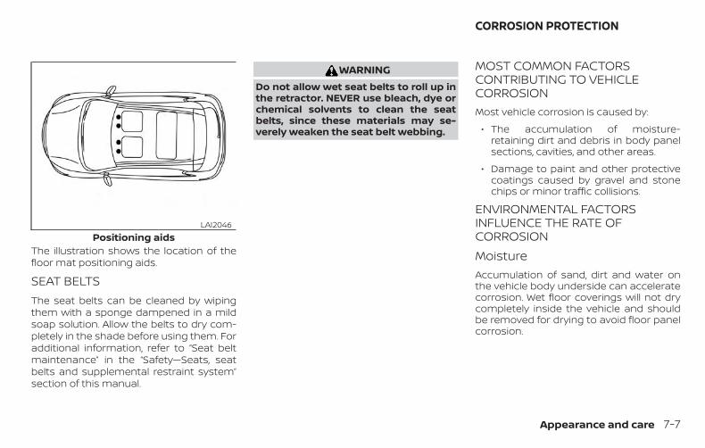
The illustration shows the location of thefloor mat positioning aids.
SEAT BELTSThe seat belts can be cleaned by wipingthem with a sponge dampened in a mildsoap solution. Allow the belts to dry com-pletely in the shade before using them. Foradditional information, refer to “Seat beltmaintenance” in the “Safety—Seats, seatbelts and supplemental restraint system”section of this manual.
WARNINGDo not allow wet seat belts to roll up inthe retractor. NEVER use bleach, dye orchemical solvents to clean the seatbelts, since these materials may se-verely weaken the seat belt webbing.
MOST COMMON FACTORSCONTRIBUTING TO VEHICLECORROSIONMost vehicle corrosion is caused by:
∙ The accumulation of moisture-retaining dirt and debris in body panelsections, cavities, and other areas.
∙ Damage to paint and other protectivecoatings caused by gravel and stonechips or minor traffic collisions.
ENVIRONMENTAL FACTORSINFLUENCE THE RATE OFCORROSIONMoistureAccumulation of sand, dirt and water onthe vehicle body underside can acceleratecorrosion. Wet floor coverings will not drycompletely inside the vehicle and shouldbe removed for drying to avoid floor panelcorrosion.
Positioning aidsLAI2046
CORROSION PROTECTION
Appearance and care 7-7
Relative humidityCorrosion will be accelerated in areas ofhigh relative humidity, especially those ar-eas where the temperatures stay abovefreezing and where atmospheric pollutionexists and road salt is used.
TemperatureHigh temperatures accelerate the rate ofcorrosion to those parts which are not wellventilated.
Air pollutionIndustrial pollution, the presence of salt inthe air in coastal areas, or heavy road saltuse accelerates the corrosion process.Road salt also accelerates the disintegra-tion of paint surfaces.
PROTECT YOUR VEHICLE FROMCORROSION
∙ Wash and wax your vehicle often tokeep the vehicle clean.
∙ Always check for minor damage to thepaint and repair it as soon as possible.
∙ Keep drain holes at the bottom of thedoors open to avoid water accumula-tion.
∙ Check the underbody for accumulationof sand, dirt or salt. If present, wash withwater as soon as possible.
CAUTION∙ NEVER remove dirt, sand or other de-
bris from the passenger compart-ment by washing it out with a hose.Remove dirt with a vacuum cleaner orbroom.
∙ Never allow water or other liquids tocome in contact with electronic com-ponents inside the vehicle as this maydamage them.
Chemicals used for road surface de-icingare extremely corrosive. They acceleratecorrosion and deterioration of underbodycomponents such as the exhaust system,fuel and brake lines, brake cables, floor panand fenders.
In winter, the underbody must be cleanedperiodically.
For additional protection against rust andcorrosion, which may be required in someareas, it is recommended that you visit aNISSAN dealer.
7-8 Appearance and care
8 Do-it-yourself
Maintenance precautions . . . . . . . . . . . . . . . . . . . . . . . 8-2Engine compartment check locations . . . . . . . . . . . 8-4Engine cooling system . . . . . . . . . . . . . . . . . . . . . . . . . . 8-6
Checking engine coolant level . . . . . . . . . . . . . . . . 8-7Changing engine coolant. . . . . . . . . . . . . . . . . . . . . 8-7
Engine oil. . . . . . . . . . . . . . . . . . . . . . . . . . . . . . . . . . . . . . . . 8-8Checking engine oil level . . . . . . . . . . . . . . . . . . . . . 8-8Changing engine oil and oil filter . . . . . . . . . . . . . . 8-9
Continuously Variable Transmission (CVT)fluid . . . . . . . . . . . . . . . . . . . . . . . . . . . . . . . . . . . . . . . . . . . . 8-13Brake fluid . . . . . . . . . . . . . . . . . . . . . . . . . . . . . . . . . . . . . . 8-13Windshield-washer fluid . . . . . . . . . . . . . . . . . . . . . . . . 8-14
Windshield-washer fluid reservoir. . . . . . . . . . . . 8-14Battery . . . . . . . . . . . . . . . . . . . . . . . . . . . . . . . . . . . . . . . . . 8-15
Jump starting . . . . . . . . . . . . . . . . . . . . . . . . . . . . . . . 8-16Variable voltage control system . . . . . . . . . . . . . . . . 8-17Drive belt . . . . . . . . . . . . . . . . . . . . . . . . . . . . . . . . . . . . . . . 8-17Spark plugs . . . . . . . . . . . . . . . . . . . . . . . . . . . . . . . . . . . . 8-18
Replacing spark plugs . . . . . . . . . . . . . . . . . . . . . . . 8-18Air cleaner. . . . . . . . . . . . . . . . . . . . . . . . . . . . . . . . . . . . . . 8-19
In-cabin microfilter . . . . . . . . . . . . . . . . . . . . . . . . . . 8-19Windshield wiper blades . . . . . . . . . . . . . . . . . . . . . . . .8-20
Cleaning . . . . . . . . . . . . . . . . . . . . . . . . . . . . . . . . . . . .8-20Replacing . . . . . . . . . . . . . . . . . . . . . . . . . . . . . . . . . . .8-20
Brakes. . . . . . . . . . . . . . . . . . . . . . . . . . . . . . . . . . . . . . . . . . 8-21Fuses. . . . . . . . . . . . . . . . . . . . . . . . . . . . . . . . . . . . . . . . . . . 8-22
Engine compartment . . . . . . . . . . . . . . . . . . . . . . . 8-22Passenger compartment. . . . . . . . . . . . . . . . . . . . 8-23
Battery replacement . . . . . . . . . . . . . . . . . . . . . . . . . . . 8-24NISSAN Intelligent Key® . . . . . . . . . . . . . . . . . . . . . . 8-25
Lights . . . . . . . . . . . . . . . . . . . . . . . . . . . . . . . . . . . . . . . . . .8-26Headlights. . . . . . . . . . . . . . . . . . . . . . . . . . . . . . . . . . . 8-26Fog lights (if so equipped) . . . . . . . . . . . . . . . . . . . 8-27Exterior and interior lights . . . . . . . . . . . . . . . . . . . 8-27
Wheels and tires. . . . . . . . . . . . . . . . . . . . . . . . . . . . . . . . 8-30Tire pressure . . . . . . . . . . . . . . . . . . . . . . . . . . . . . . . . 8-30Tire labeling . . . . . . . . . . . . . . . . . . . . . . . . . . . . . . . . . 8-34Types of tires . . . . . . . . . . . . . . . . . . . . . . . . . . . . . . . . 8-36Tire chains . . . . . . . . . . . . . . . . . . . . . . . . . . . . . . . . . . 8-37Changing wheels and tires . . . . . . . . . . . . . . . . . . 8-39
When performing any inspection or main-tenance work on your vehicle, always takecare to prevent serious accidental injury toyourself or damage to the vehicle. The fol-lowing are general precautions whichshould be closely observed.
WARNING∙ Park the vehicle on a level surface, ap-
ply the parking brake securely andblock the wheels to prevent the ve-hicle from moving. Move the shift le-ver to P (Park).
∙ Be sure the ignition key is in the OFF orLOCK position when performing anyparts replacement or repairs.
∙ If you must work with the engine run-ning, keep your hands, clothing, hairand tools away from moving fans,belts and any other moving parts.
∙ It is advisable to secure or remove anyloose clothing and remove any jew-elry, such as rings, watches, etc. be-fore working on your vehicle.
∙ Always wear eye protection wheneveryou work on your vehicle.
∙ Your vehicle is equipped with an auto-matic engine cooling fan. It may comeon at any time without warning, evenif the ignition key is in the OFF positionand the engine is not running. Toavoid injury, always disconnect thenegative battery cable before work-ing near the fan.
∙ If you must run the engine in an en-closed space such as a garage, be surethere is proper ventilation for exhaustgases to escape.
∙ Never get under the vehicle while it issupported only by a jack. If it is neces-sary to work under the vehicle, sup-port it with safety stands.
∙ Keep smoking materials, flame andsparks away from the fuel tank andbattery.
∙ On gasoline engine models, the fuelfilter or fuel lines should be serviced. Itis recommended that you visit aNISSAN dealer for this service becausethe fuel lines are under high pressureeven when the engine is off.
CAUTION∙ Do not work under the hood while the
engine is hot. Turn the engine off andwait until it cools down.
∙ Avoid contact with used engine oiland coolant. Improperly disposed en-gine oil, engine coolant and/or othervehicle fluids can damage the envi-ronment. Always conform to localregulations for disposal of vehiclefluid.
∙ Never leave the engine or the trans-mission related component harnessconnector disconnected while the ig-nition switch is in the ON position.
∙ Never connect or disconnect the bat-tery or any transistorized componentwhile the ignition switch is in the ONposition.
MAINTENANCE PRECAUTIONS
8-2 Do-it-yourself
This “Do-it-yourself ” section gives instruc-tions regarding only those items which arerelatively easy for an owner to perform.
A Genuine NISSAN service manual is alsoavailable. For additional information, referto “Owner’s Manual/Service Manual orderinformation” in the “Technical and con-sumer information” section of this manual.
You should be aware that incomplete orimproper servicing may result in operatingdifficulties or excessive emissions, andcould affect warranty coverage. If in doubtabout any servicing, it is recommendedthat you have it done by a NISSAN dealer.
Do-it-yourself 8-3
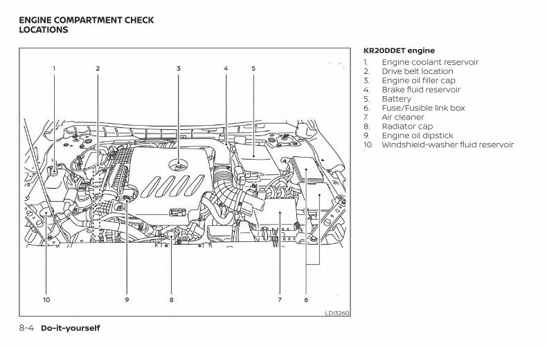
KR20DDET engine1. Engine coolant reservoir2. Drive belt location3. Engine oil filler cap4. Brake fluid reservoir5. Battery6. Fuse/Fusible link box7. Air cleaner8. Radiator cap9. Engine oil dipstick10. Windshield-washer fluid reservoir
LDI3260
ENGINE COMPARTMENT CHECKLOCATIONS
8-4 Do-it-yourself
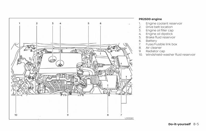
PR25DD engine1. Engine coolant reservoir2. Drive belt location3. Engine oil filler cap4. Engine oil dipstick5. Brake fluid reservoir6. Battery7. Fuse/Fusible link box8. Air cleaner9. Radiator cap10. Windshield-washer fluid reservoir
LDI3261
Do-it-yourself 8-5
The engine cooling system is filled at thefactory with a pre-diluted mixture of50% Genuine NISSAN Long LifeAntifreeze/Coolant (blue) and 50% water toprovide year-round antifreeze and coolantprotection. The antifreeze solution con-tains rust and corrosion inhibitors. Addi-tional engine cooling system additives arenot necessary.
WARNING∙ Never remove the radiator or coolant
reservoir cap when the engine is hot.Wait until the engine and radiator cooldown. Serious burns could be causedby high pressure fluid escaping fromthe radiator. For additional informa-tion on precautions, refer to “If yourvehicle overheats” in the “In case ofemergency” section of this manual.
∙ The radiator is equipped with a pres-sure type radiator cap. To prevent en-gine damage, use only a GenuineNISSAN radiator cap.
CAUTION∙ Never use any cooling system addi-
tives such as radiator sealer. Additivesmay clog the cooling system andcause damage to the engine, trans-mission and/or cooling system.
∙ When adding or replacing coolant, besure to use only Genuine NISSAN LongLife Antifreeze/Coolant (blue) orequivalent. Genuine NISSAN Long LifeAntifreeze/Coolant (blue) is pre-diluted to provide antifreeze protec-tion to -34° F (-37° C). If additionalfreeze protection is needed due toweather where you operate your ve-hicle, add Genuine NISSAN Long LifeAntifreeze/Coolant (blue) concen-trate following the directions on thecontainer. If an equivalent coolantother than Genuine NISSAN Long LifeAntifreeze/Coolant (blue) is used, fol-low the coolant manufacturer’s in-structions to maintain minimum anti-freeze protection to -34° F (-37° C). Theuse of other types of coolant solu-tions other than Genuine NISSAN LongLife Antifreeze/Coolant (blue) orequivalent may damage the enginecooling system.
∙ The life expectancy of the factory-fillcoolant is 105,000 miles (168,000 km)or 7 years. Mixing any other type ofcoolant other than Genuine NISSANLong Life Antifreeze/Coolant (blue),including Genuine NISSAN Long LifeAntifreeze/Coolant (green), or the useof non-distilled water will reduce thelife expectancy of the factory-fill cool-ant. For additional information, referto the "Maintenance and schedules"section of this manual.
ENGINE COOLING SYSTEM
8-6 Do-it-yourself
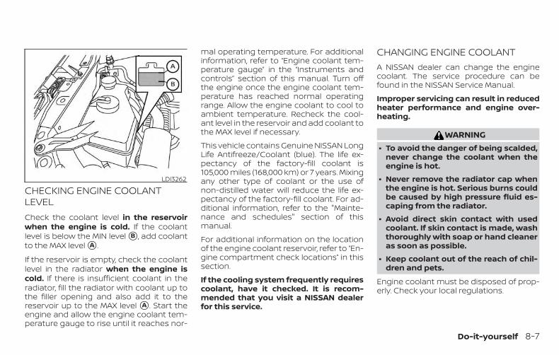
CHECKING ENGINE COOLANTLEVELCheck the coolant level in the reservoirwhen the engine is cold. If the coolantlevel is below the MIN level �B , add coolantto the MAX level �A .
If the reservoir is empty, check the coolantlevel in the radiator when the engine iscold. If there is insufficient coolant in theradiator, fill the radiator with coolant up tothe filler opening and also add it to thereservoir up to the MAX level �A . Start theengine and allow the engine coolant tem-perature gauge to rise until it reaches nor-
mal operating temperature. For additionalinformation, refer to “Engine coolant tem-perature gauge” in the “Instruments andcontrols” section of this manual. Turn offthe engine once the engine coolant tem-perature has reached normal operatingrange. Allow the engine coolant to cool toambient temperature. Recheck the cool-ant level in the reservoir and add coolant tothe MAX level if necessary.
This vehicle contains Genuine NISSAN LongLife Antifreeze/Coolant (blue). The life ex-pectancy of the factory-fill coolant is105,000 miles (168,000 km) or 7 years. Mixingany other type of coolant or the use ofnon-distilled water will reduce the life ex-pectancy of the factory-fill coolant. For ad-ditional information, refer to the "Mainte-nance and schedules" section of thismanual.
For additional information on the locationof the engine coolant reservoir, refer to “En-gine compartment check locations” in thissection.
If the cooling system frequently requirescoolant, have it checked. It is recom-mended that you visit a NISSAN dealerfor this service.
CHANGING ENGINE COOLANTA NISSAN dealer can change the enginecoolant. The service procedure can befound in the NISSAN Service Manual.
Improper servicing can result in reducedheater performance and engine over-heating.
WARNING∙ To avoid the danger of being scalded,
never change the coolant when theengine is hot.
∙ Never remove the radiator cap whenthe engine is hot. Serious burns couldbe caused by high pressure fluid es-caping from the radiator.
∙ Avoid direct skin contact with usedcoolant. If skin contact is made, washthoroughly with soap or hand cleaneras soon as possible.
∙ Keep coolant out of the reach of chil-dren and pets.
Engine coolant must be disposed of prop-erly. Check your local regulations.
LDI3262
Do-it-yourself 8-7
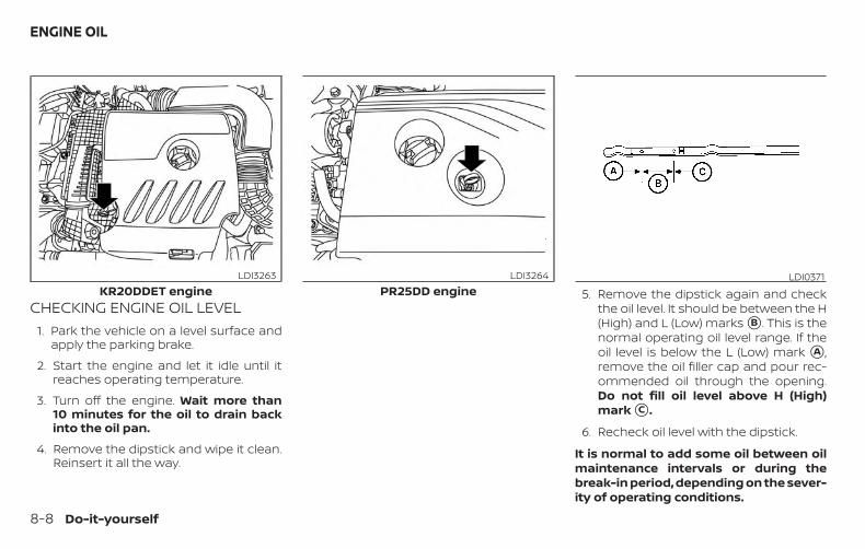
CHECKING ENGINE OIL LEVEL1. Park the vehicle on a level surface and
apply the parking brake.
2. Start the engine and let it idle until itreaches operating temperature.
3. Turn off the engine. Wait more than10 minutes for the oil to drain backinto the oil pan.
4. Remove the dipstick and wipe it clean.Reinsert it all the way.
5. Remove the dipstick again and checkthe oil level. It should be between the H(High) and L (Low) marks �B . This is thenormal operating oil level range. If theoil level is below the L (Low) mark �A ,remove the oil filler cap and pour rec-ommended oil through the opening.Do not fill oil level above H (High)mark �C .
6. Recheck oil level with the dipstick.
It is normal to add some oil between oilmaintenance intervals or during thebreak-in period, depending on the sever-ity of operating conditions.
KR20DDET engineLDI3263
PR25DD engineLDI3264 LDI0371
ENGINE OIL
8-8 Do-it-yourself
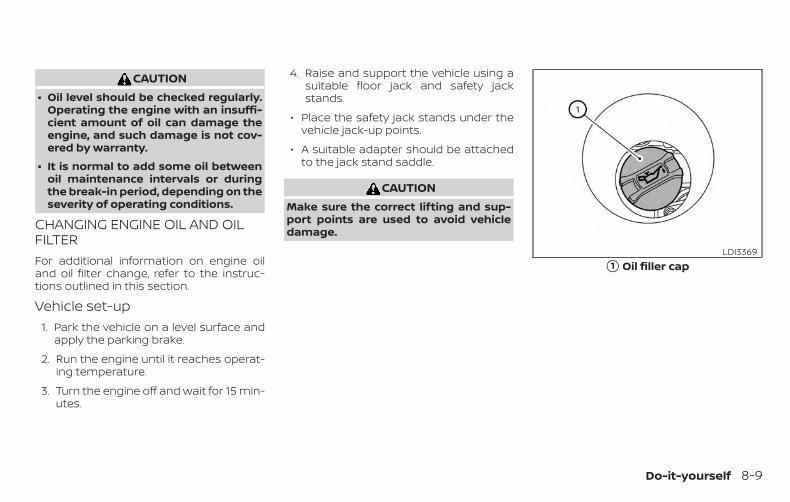
CAUTION∙ Oil level should be checked regularly.
Operating the engine with an insuffi-cient amount of oil can damage theengine, and such damage is not cov-ered by warranty.
∙ It is normal to add some oil betweenoil maintenance intervals or duringthe break-in period, depending on theseverity of operating conditions.
CHANGING ENGINE OIL AND OILFILTERFor additional information on engine oiland oil filter change, refer to the instruc-tions outlined in this section.
Vehicle set-up1. Park the vehicle on a level surface and
apply the parking brake.
2. Run the engine until it reaches operat-ing temperature.
3. Turn the engine off and wait for 15 min-utes.
4. Raise and support the vehicle using asuitable floor jack and safety jackstands.
∙ Place the safety jack stands under thevehicle jack-up points.
∙ A suitable adapter should be attachedto the jack stand saddle.
CAUTIONMake sure the correct lifting and sup-port points are used to avoid vehicledamage.
�1 Oil filler capLDI3369
Do-it-yourself 8-9
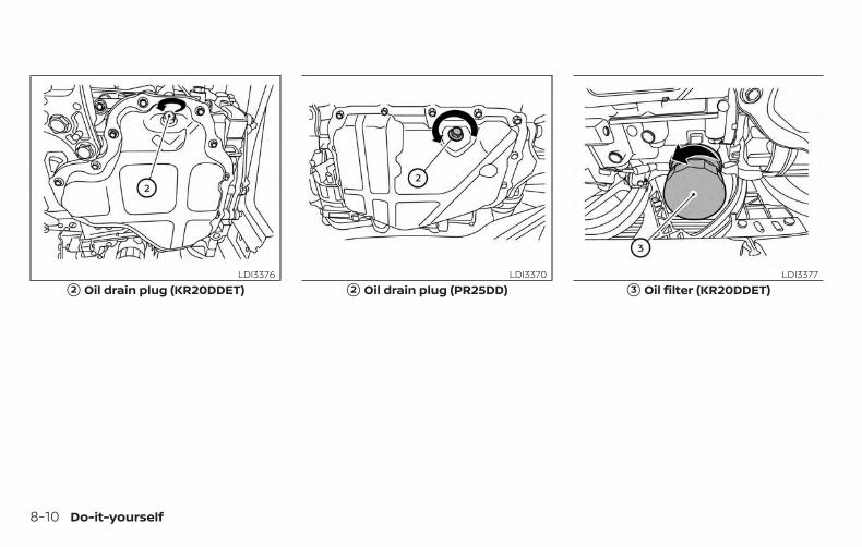
�2 Oil drain plug (KR20DDET)LDI3376
�2 Oil drain plug (PR25DD)LDI3370
�3 Oil filter (KR20DDET)LDI3377
8-10 Do-it-yourself
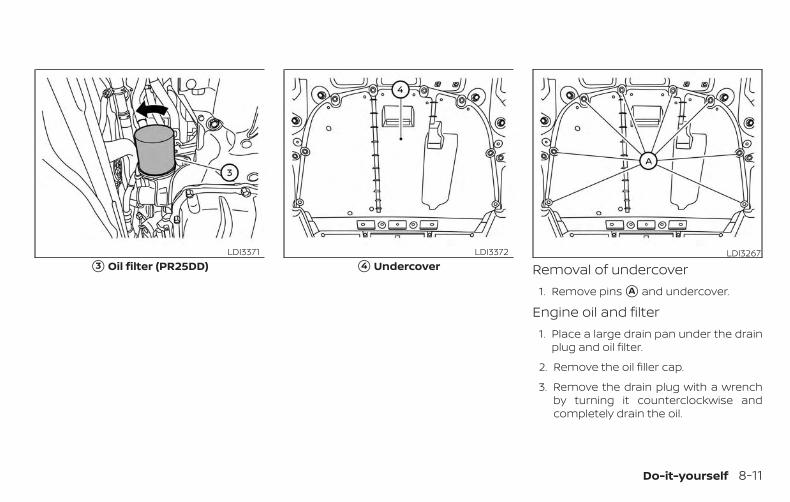
Removal of undercover1. Remove pins �A and undercover.
Engine oil and filter1. Place a large drain pan under the drain
plug and oil filter.
2. Remove the oil filler cap.
3. Remove the drain plug with a wrenchby turning it counterclockwise andcompletely drain the oil.
�3 Oil filter (PR25DD)LDI3371
�4 UndercoverLDI3372 LDI3267
Do-it-yourself 8-11
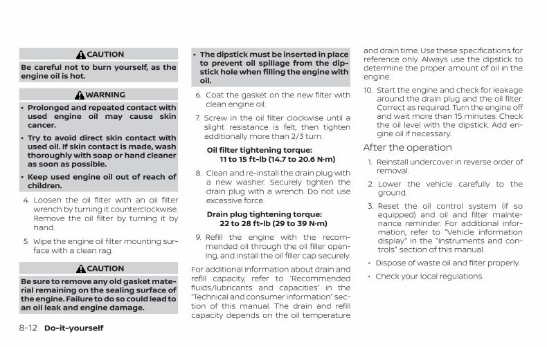
CAUTIONBe careful not to burn yourself, as theengine oil is hot.
WARNING∙ Prolonged and repeated contact with
used engine oil may cause skincancer.
∙ Try to avoid direct skin contact withused oil. If skin contact is made, washthoroughly with soap or hand cleaneras soon as possible.
∙ Keep used engine oil out of reach ofchildren.
4. Loosen the oil filter with an oil filterwrench by turning it counterclockwise.Remove the oil filter by turning it byhand.
5. Wipe the engine oil filter mounting sur-face with a clean rag.
CAUTIONBe sure to remove any old gasket mate-rial remaining on the sealing surface ofthe engine. Failure to do so could lead toan oil leak and engine damage.
∙ The dipstick must be inserted in placeto prevent oil spillage from the dip-stick hole when filling the engine withoil.
6. Coat the gasket on the new filter withclean engine oil.
7. Screw in the oil filter clockwise until aslight resistance is felt, then tightenadditionally more than 2/3 turn.
Oil filter tightening torque:11 to 15 ft-lb (14.7 to 20.6 N·m)
8. Clean and re-install the drain plug witha new washer. Securely tighten thedrain plug with a wrench. Do not useexcessive force.
Drain plug tightening torque:22 to 28 ft-lb (29 to 39 N·m)
9. Refill the engine with the recom-mended oil through the oil filler open-ing, and install the oil filler cap securely.
For additional information about drain andrefill capacity, refer to “Recommendedfluids/lubricants and capacities” in the“Technical and consumer information” sec-tion of this manual. The drain and refillcapacity depends on the oil temperature
and drain time. Use these specifications forreference only. Always use the dipstick todetermine the proper amount of oil in theengine.
10. Start the engine and check for leakagearound the drain plug and the oil filter.Correct as required. Turn the engine offand wait more than 15 minutes. Checkthe oil level with the dipstick. Add en-gine oil if necessary.
After the operation1. Reinstall undercover in reverse order of
removal.
2. Lower the vehicle carefully to theground.
3. Reset the oil control system (if soequipped) and oil and filter mainte-nance reminder. For additional infor-mation, refer to "Vehicle informationdisplay" in the "Instruments and con-trols" section of this manual.
∙ Dispose of waste oil and filter properly.
∙ Check your local regulations.
8-12 Do-it-yourself
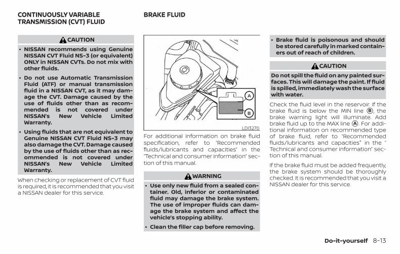
CAUTION∙ NISSAN recommends using Genuine
NISSAN CVT Fluid NS-3 (or equivalent)ONLY in NISSAN CVTs. Do not mix withother fluids.
∙ Do not use Automatic TransmissionFluid (ATF) or manual transmissionfluid in a NISSAN CVT, as it may dam-age the CVT. Damage caused by theuse of fluids other than as recom-mended is not covered underNISSAN’s New Vehicle LimitedWarranty.
∙ Using fluids that are not equivalent toGenuine NISSAN CVT Fluid NS-3 mayalso damage the CVT. Damage causedby the use of fluids other than as rec-ommended is not covered underNISSAN’s New Vehicle LimitedWarranty.
When checking or replacement of CVT fluidis required, it is recommended that you visita NISSAN dealer for this service.
For additional information on brake fluidspecification, refer to “Recommendedfluids/lubricants and capacities” in the“Technical and consumer information” sec-tion of this manual.
WARNING∙ Use only new fluid from a sealed con-
tainer. Old, inferior or contaminatedfluid may damage the brake system.The use of improper fluids can dam-age the brake system and affect thevehicle’s stopping ability.
∙ Clean the filler cap before removing.
∙ Brake fluid is poisonous and shouldbe stored carefully in marked contain-ers out of reach of children.
CAUTIONDo not spill the fluid on any painted sur-faces. This will damage the paint. If fluidis spilled, immediately wash the surfacewith water.
Check the fluid level in the reservoir. If thebrake fluid is below the MIN line �B , thebrake warning light will illuminate. Addbrake fluid up to the MAX line �A . For addi-tional information on recommended typeof brake fluid, refer to “Recommendedfluids/lubricants and capacities" in the “Technical and consumer information” sec-tion of this manual.
If the brake fluid must be added frequently,the brake system should be thoroughlychecked. It is recommended that you visit aNISSAN dealer for this service.
LDI3270
CONTINUOUSLY VARIABLETRANSMISSION (CVT) FLUID
BRAKE FLUID
Do-it-yourself 8-13
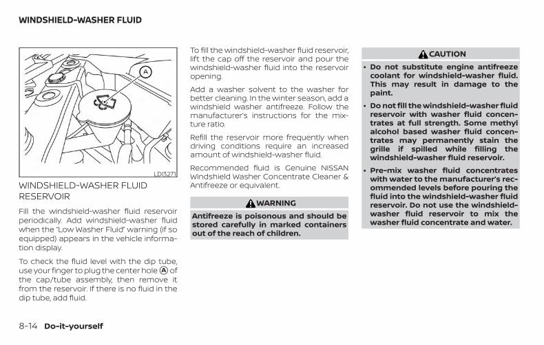
WINDSHIELD-WASHER FLUIDRESERVOIRFill the windshield-washer fluid reservoirperiodically. Add windshield-washer fluidwhen the “Low Washer Fluid” warning (if soequipped) appears in the vehicle informa-tion display.
To check the fluid level with the dip tube,use your finger to plug the center hole �A ofthe cap/tube assembly, then remove itfrom the reservoir. If there is no fluid in thedip tube, add fluid.
To fill the windshield-washer fluid reservoir,lift the cap off the reservoir and pour thewindshield-washer fluid into the reservoiropening.
Add a washer solvent to the washer forbetter cleaning. In the winter season, add awindshield washer antifreeze. Follow themanufacturer’s instructions for the mix-ture ratio.
Refill the reservoir more frequently whendriving conditions require an increasedamount of windshield-washer fluid.
Recommended fluid is Genuine NISSANWindshield Washer Concentrate Cleaner &Antifreeze or equivalent.
WARNINGAntifreeze is poisonous and should bestored carefully in marked containersout of the reach of children.
CAUTION∙ Do not substitute engine antifreeze
coolant for windshield-washer fluid.This may result in damage to thepaint.
∙ Do not fill the windshield-washer fluidreservoir with washer fluid concen-trates at full strength. Some methylalcohol based washer fluid concen-trates may permanently stain thegrille if spilled while filling thewindshield-washer fluid reservoir.
∙ Pre-mix washer fluid concentrateswith water to the manufacturer’s rec-ommended levels before pouring thefluid into the windshield-washer fluidreservoir. Do not use the windshield-washer fluid reservoir to mix thewasher fluid concentrate and water.
LDI3271
WINDSHIELD-WASHER FLUID
8-14 Do-it-yourself
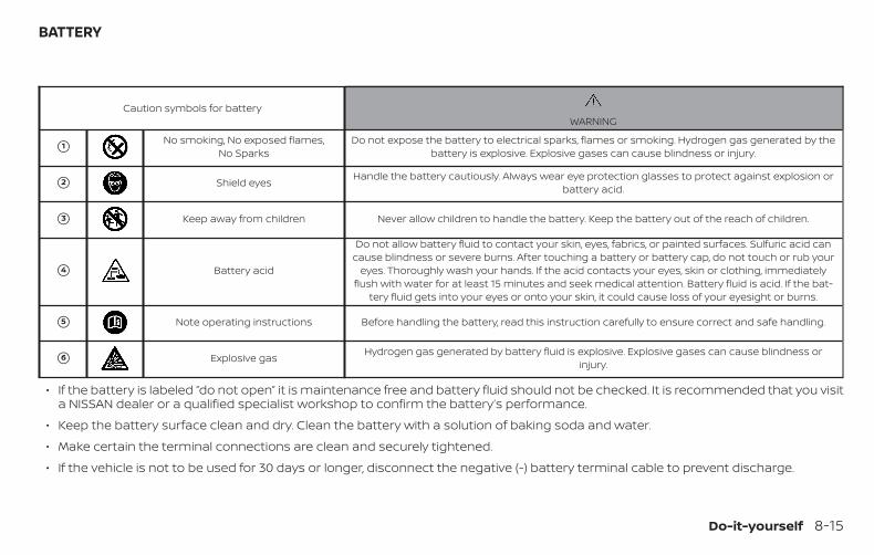
Caution symbols for batteryWARNING
�1 No smoking, No exposed flames,No Sparks
Do not expose the battery to electrical sparks, flames or smoking. Hydrogen gas generated by thebattery is explosive. Explosive gases can cause blindness or injury.
�2 Shield eyes Handle the battery cautiously. Always wear eye protection glasses to protect against explosion orbattery acid.
�3 Keep away from children Never allow children to handle the battery. Keep the battery out of the reach of children.
�4 Battery acid
Do not allow battery fluid to contact your skin, eyes, fabrics, or painted surfaces. Sulfuric acid cancause blindness or severe burns. After touching a battery or battery cap, do not touch or rub your
eyes. Thoroughly wash your hands. If the acid contacts your eyes, skin or clothing, immediatelyflush with water for at least 15 minutes and seek medical attention. Battery fluid is acid. If the bat-
tery fluid gets into your eyes or onto your skin, it could cause loss of your eyesight or burns.
�5 Note operating instructions Before handling the battery, read this instruction carefully to ensure correct and safe handling.
�6 Explosive gas Hydrogen gas generated by battery fluid is explosive. Explosive gases can cause blindness orinjury.
∙ If the battery is labeled “do not open” it is maintenance free and battery fluid should not be checked. It is recommended that you visita NISSAN dealer or a qualified specialist workshop to confirm the battery’s performance.
∙ Keep the battery surface clean and dry. Clean the battery with a solution of baking soda and water.
∙ Make certain the terminal connections are clean and securely tightened.
∙ If the vehicle is not to be used for 30 days or longer, disconnect the negative (-) battery terminal cable to prevent discharge.
BATTERY
Do-it-yourself 8-15
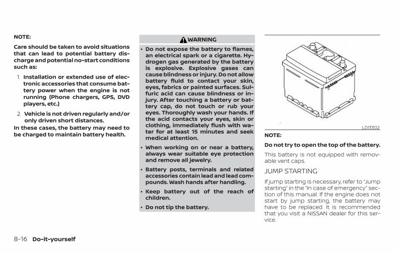
NOTE:
Care should be taken to avoid situationsthat can lead to potential battery dis-charge and potential no-start conditionssuch as:
1. Installation or extended use of elec-tronic accessories that consume bat-tery power when the engine is notrunning (Phone chargers, GPS, DVDplayers, etc.)
2. Vehicle is not driven regularly and/oronly driven short distances.
In these cases, the battery may need tobe charged to maintain battery health.
WARNING∙ Do not expose the battery to flames,
an electrical spark or a cigarette. Hy-drogen gas generated by the batteryis explosive. Explosive gases cancause blindness or injury. Do not allowbattery fluid to contact your skin,eyes, fabrics or painted surfaces. Sul-furic acid can cause blindness or in-jury. After touching a battery or bat-tery cap, do not touch or rub youreyes. Thoroughly wash your hands. Ifthe acid contacts your eyes, skin orclothing, immediately flush with wa-ter for at least 15 minutes and seekmedical attention.
∙ When working on or near a battery,always wear suitable eye protectionand remove all jewelry.
∙ Battery posts, terminals and relatedaccessories contain lead and lead com-pounds. Wash hands after handling.
∙ Keep battery out of the reach ofchildren.
∙ Do not tip the battery.
NOTE:
Do not try to open the top of the battery.
This battery is not equipped with remov-able vent caps.
JUMP STARTINGIf jump starting is necessary, refer to “Jumpstarting” in the “In case of emergency” sec-tion of this manual. If the engine does notstart by jump starting, the battery mayhave to be replaced. It is recommendedthat you visit a NISSAN dealer for this ser-vice.
LDI3302
8-16 Do-it-yourself
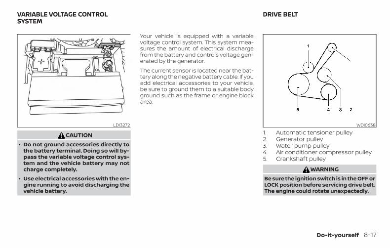
CAUTION∙ Do not ground accessories directly to
the battery terminal. Doing so will by-pass the variable voltage control sys-tem and the vehicle battery may notcharge completely.
∙ Use electrical accessories with the en-gine running to avoid discharging thevehicle battery.
Your vehicle is equipped with a variablevoltage control system. This system mea-sures the amount of electrical dischargefrom the battery and controls voltage gen-erated by the generator.
The current sensor is located near the bat-tery along the negative battery cable. If youadd electrical accessories to your vehicle,be sure to ground them to a suitable bodyground such as the frame or engine blockarea.
1. Automatic tensioner pulley2. Generator pulley3. Water pump pulley4. Air conditioner compressor pulley5. Crankshaft pulley
WARNINGBe sure the ignition switch is in the OFF orLOCK position before servicing drive belt.The engine could rotate unexpectedly.
LDI3272 WDI0638
VARIABLE VOLTAGE CONTROLSYSTEM
DRIVE BELT
Do-it-yourself 8-17
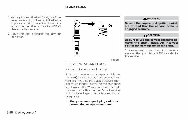
1. Visually inspect the belt for signs of un-usual wear, cuts, or fraying. If the belt isin poor condition, have it replaced. It isrecommended that you visit a NISSANdealer for this service.
2. Have the belt checked regularly forcondition.
REPLACING SPARK PLUGSIridium-tipped spark plugsIt is not necessary to replace iridium-tipped �A spark plugs as frequently as con-ventional type spark plugs because theylast much longer. Follow the maintenancelog shown in the “Maintenance and sched-ules” section of this manual. Do not serviceiridium-tipped spark plugs by cleaning orregapping.
∙ Always replace spark plugs with rec-ommended or equivalent ones.
WARNINGBe sure the engine and ignition switchare off and that the parking brake isengaged securely.
CAUTIONBe sure to use the correct socket to re-move the spark plugs. An incorrectsocket can damage the spark plugs.
If replacement is required, it is recom-mended that you visit a NISSAN dealer forthis service.
SDI1895
SPARK PLUGS
8-18 Do-it-yourself
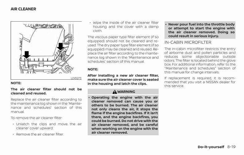
NOTE:
The air cleaner filter should not becleaned and reused.
Replace the air cleaner filter according tothe maintenance log shown in the ”Mainte-nance and schedules” section of thismanual.
To remove the air cleaner filter:
∙ Unlatch the clips and move the aircleaner cover upward.
∙ Remove the air cleaner filter.
∙ Wipe the inside of the air cleaner filterhousing and the cover with a dampcloth.
The viscous paper type filter element (if soequipped) should not be cleaned and re-used. The dry paper type filter element (if soequipped) may be cleaned and reused. Re-place the air filter according to the mainte-nance log shown in the “Maintenance andschedules” section of this manual.
NOTE:
After installing a new air cleaner filter,make sure the air cleaner cover is seatedin the housing and latch the clips.
WARNING∙ Operating the engine with the air
cleaner removed can cause you orothers to be burned. The air cleanernot only cleans the air, it stops theflame if the engine backfires. If it isn’tthere, and the engine backfires, youcould be burned. Do not drive with theair cleaner removed, and be carefulwhen working on the engine with theair cleaner removed.
∙ Never pour fuel into the throttle bodyor attempt to start the engine withthe air cleaner removed. Doing socould result in serious injury.
IN-CABIN MICROFILTERThe in-cabin microfilter restricts the entryof airborne dust and pollen particles andreduces some objectionable outsideodors. The filter is located behind the glovebox. For additional information, refer to the"Maintenance and schedules" section ofthis manual for change intervals.
If replacement is required, it is recom-mended that you visit a NISSAN dealer forthis service.
LDI3273
AIR CLEANER
Do-it-yourself 8-19
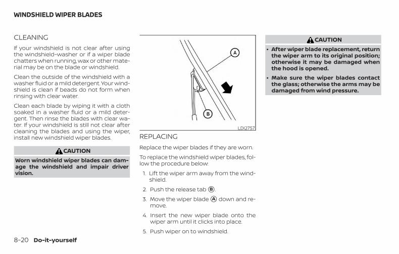
CLEANINGIf your windshield is not clear after usingthe windshield–washer or if a wiper bladechatters when running, wax or other mate-rial may be on the blade or windshield.
Clean the outside of the windshield with awasher fluid or a mild detergent. Your wind-shield is clean if beads do not form whenrinsing with clear water.
Clean each blade by wiping it with a clothsoaked in a washer fluid or a mild deter-gent. Then rinse the blades with clear wa-ter. If your windshield is still not clear aftercleaning the blades and using the wiper,install new windshield wiper blades.
CAUTIONWorn windshield wiper blades can dam-age the windshield and impair drivervision.
REPLACINGReplace the wiper blades if they are worn.
To replace the windshield wiper blades, fol-low the procedure below:
1. Lift the wiper arm away from the wind-shield.
2. Push the release tab �B .
3. Move the wiper blade �A down and re-move.
4. Insert the new wiper blade onto thewiper arm until it clicks into place.
5. Push wiper on to windshield.
CAUTION∙ After wiper blade replacement, return
the wiper arm to its original position;otherwise it may be damaged whenthe hood is opened.
∙ Make sure the wiper blades contactthe glass; otherwise the arms may bedamaged from wind pressure.
LDI2757
WINDSHIELD WIPER BLADES
8-20 Do-it-yourself
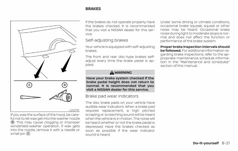
If you wax the surface of the hood, be care-ful not to let wax get into the washer nozzle�D . This may cause clogging or improperwindshield-washer operation. If wax getsinto the nozzle, remove it with a needle orsmall pin �C .
If the brakes do not operate properly, havethe brakes checked. It is recommendedthat you visit a NISSAN dealer for this ser-vice.
Self-adjusting brakesYour vehicle is equipped with self-adjustingbrakes.
The front and rear disc-type brakes self-adjust every time the brake pedal is ap-plied.
WARNINGHave your brake system checked if thebrake pedal height does not return tonormal. It is recommended that youvisit a NISSAN dealer for this service.
Brake pad wear indicatorsThe disc brake pads on your vehicle haveaudible wear indicators. When a brake padrequires replacement, a high pitchedscraping or screeching sound will be heardwhen the vehicle is in motion. The noise willbe heard whether or not the brake pedal isdepressed. Have the brakes checked assoon as possible if the wear indicatorsound is heard.
Under some driving or climate conditions,occasional brake squeak, squeal or othernoise may be heard. Occasional brakenoise during light to moderate stops is nor-mal and does not affect the function orperformance of the brake system.
Proper brake inspection intervals shouldbe followed. For additional information re-garding brake inspections, refer to the ap-propriate maintenance schedule informa-tion in the "Maintenance and schedules"section of this manual.
LDI2731
BRAKES
Do-it-yourself 8-21
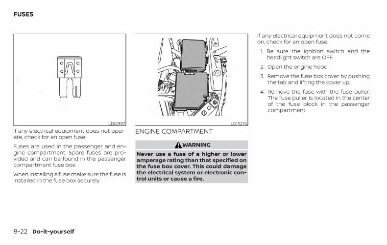
If any electrical equipment does not oper-ate, check for an open fuse.
Fuses are used in the passenger and en-gine compartment. Spare fuses are pro-vided and can be found in the passengercompartment fuse box.
When installing a fuse make sure the fuse isinstalled in the fuse box securely.
ENGINE COMPARTMENT
WARNINGNever use a fuse of a higher or loweramperage rating than that specified onthe fuse box cover. This could damagethe electrical system or electronic con-trol units or cause a fire.
If any electrical equipment does not comeon, check for an open fuse.
1. Be sure the ignition switch and theheadlight switch are OFF.
2. Open the engine hood.
3. Remove the fuse box cover by pushingthe tab and lifting the cover up.
4. Remove the fuse with the fuse puller.The fuse puller is located in the centerof the fuse block in the passengercompartment.
LDI2997 LDI3274
FUSES
8-22 Do-it-yourself
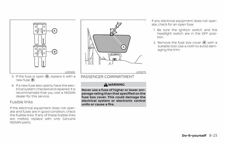
5. If the fuse is open �A , replace it with anew fuse �B .
6. If a new fuse also opens, have the elec-trical system checked and repaired. It isrecommended that you visit a NISSANdealer for this service.
Fusible linksIf the electrical equipment does not oper-ate and fuses are in good condition, checkthe fusible links. If any of these fusible linksare melted, replace with only GenuineNISSAN parts.
PASSENGER COMPARTMENT
WARNINGNever use a fuse of higher or lower am-perage rating than that specified on thefuse box cover. This could damage theelectrical system or electronic controlunits or cause a fire.
If any electrical equipment does not oper-ate, check for an open fuse.
1. Be sure the ignition switch and theheadlight switch are in the OFF posi-tion.
2. Remove the fuse box cover �A with asuitable tool. Use a cloth to avoid dam-aging the trim.
LDI3200 LDI3275
Do-it-yourself 8-23
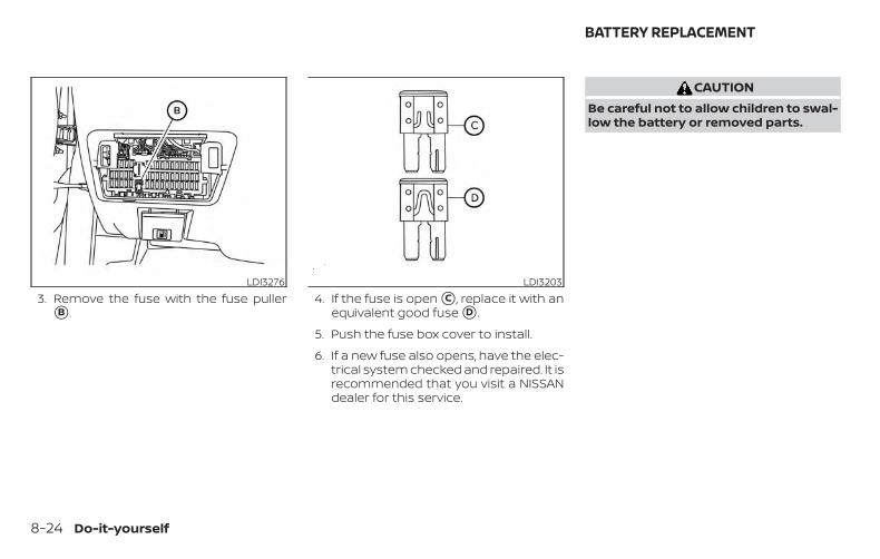
3. Remove the fuse with the fuse puller�B .
4. If the fuse is open �C , replace it with anequivalent good fuse �D .
5. Push the fuse box cover to install.
6. If a new fuse also opens, have the elec-trical system checked and repaired. It isrecommended that you visit a NISSANdealer for this service.
CAUTIONBe careful not to allow children to swal-low the battery or removed parts.
LDI3276 LDI3203
BATTERY REPLACEMENT
8-24 Do-it-yourself
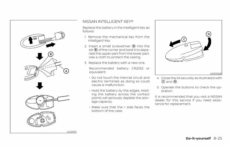
NISSAN INTELLIGENT KEY®Replace the battery in the Intelligent Key asfollows:
1. Remove the mechanical key from theIntelligent Key.
2. Insert a small screwdriver �A into theslit �B of the corner and twist it to sepa-rate the upper part from the lower part.Use a cloth to protect the casing.
3. Replace the battery with a new one.
Recommended battery: CR2032 orequivalent.
∙ Do not touch the internal circuit andelectric terminals as doing so couldcause a malfunction.
∙ Hold the battery by the edges. Hold-ing the battery across the contactpoints will seriously deplete the stor-age capacity.
∙ Make sure that the + side faces thebottom of the case.
4. Close the lid securely as illustrated with�C and �D .
5. Operate the buttons to check the op-eration.
It is recommended that you visit a NISSANdealer for this service if you need assis-tance for replacement.
LDI2001
WDI0568
Do-it-yourself 8-25
FCC Notice:
For USA:This device complies with Part 15 of theFCC Rules. Operation is subject to the fol-lowing two conditions: (1) This devicemay not cause harmful interference, and(2) this device must accept any interfer-ence received, including interferencethat may cause undesired operation.
Note: Changes or modifications not ex-pressly approved by the party respon-sible for compliance could void the user’sauthority to operate the equipment.
For Canada:This device complies with IndustryCanada licence-exempt RSS standard(s).Operation is subject to the following twoconditions: (1) this device may not causeinterference, and (2) this device must ac-cept any interference, including interfer-ence that may cause undesired opera-tion of the device.
HEADLIGHTSFor additional information on headlightbulb replacement, refer to the instructionsoutlined in this section.
Replacing the halogen headlightbulb (if so equipped)The headlight is a semi-sealed beam typewhich uses a replaceable headlight (halo-gen) bulb. They can be replaced from insidethe engine compartment without remov-ing the headlight assembly.
If headlight bulb replacement is required, itis recommended that you visit a NISSANdealer for this service.
CAUTION∙ Aiming is not necessary after replac-
ing the bulb. When aiming adjustmentis necessary, it is recommended thatyou visit a NISSAN dealer for thisservice.
∙ Do not leave the headlight assemblyopen without a bulb installed for along period of time. Dust, moisture,smoke, etc. entering the headlightbody may affect bulb performance.Remove the bulb from the headlightassembly just before a replacementbulb is installed.
∙ Only touch the base when handlingthe bulb. Never touch the glass enve-lope. Touching the glass could signifi-cantly affect bulb life and/or head-light performance.
∙ High pressure halogen gas is sealedinside the halogen bulb. The bulbmay break if the glass envelope isscratched or the bulb is dropped.
∙ Use the same number and wattage asshown in the chart.
Fog may temporarily form inside the lensof the exterior lights in the rain or in a carwash. A temperature difference betweenthe inside and the outside of the lenscauses the fog. This is not a malfunction. Iflarge drops of water collect inside the lens,it is recommended that you visit a NISSANdealer for this service.
LIGHTS
8-26 Do-it-yourself
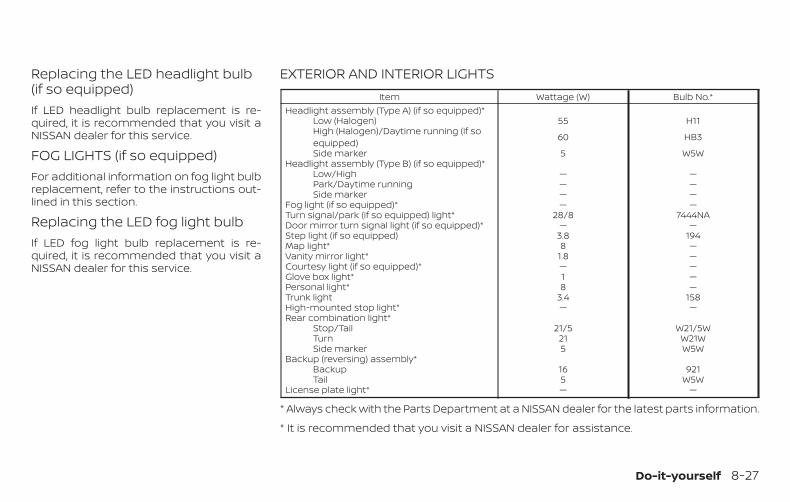
Replacing the LED headlight bulb(if so equipped)If LED headlight bulb replacement is re-quired, it is recommended that you visit aNISSAN dealer for this service.
FOG LIGHTS (if so equipped)For additional information on fog light bulbreplacement, refer to the instructions out-lined in this section.
Replacing the LED fog light bulbIf LED fog light bulb replacement is re-quired, it is recommended that you visit aNISSAN dealer for this service.
EXTERIOR AND INTERIOR LIGHTSItem Wattage (W) Bulb No.*
Headlight assembly (Type A) (if so equipped)*Low (Halogen) 55 H11High (Halogen)/Daytime running (if soequipped) 60 HB3
Side marker 5 W5WHeadlight assembly (Type B) (if so equipped)*
Low/High — —Park/Daytime running — —Side marker — —
Fog light (if so equipped)* — —Turn signal/park (if so equipped) light* 28/8 7444NADoor mirror turn signal light (if so equipped)* — —Step light (if so equipped) 3.8 194Map light* 8 —Vanity mirror light* 1.8 —Courtesy light (if so equipped)* — —Glove box light* 1 —Personal light* 8 —Trunk light 3.4 158High-mounted stop light* — —Rear combination light*
Stop/Tail 21/5 W21/5WTurn 21 W21WSide marker 5 W5W
Backup (reversing) assembly*Backup 16 921Tail 5 W5W
License plate light* — —
* Always check with the Parts Department at a NISSAN dealer for the latest parts information.
* It is recommended that you visit a NISSAN dealer for assistance.
Do-it-yourself 8-27
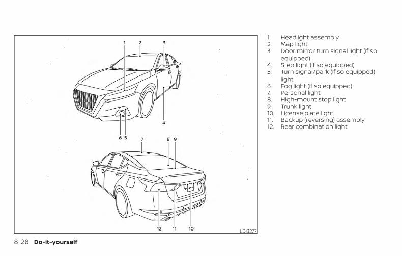
1. Headlight assembly2. Map light3. Door mirror turn signal light (if so
equipped)4. Step light (if so equipped)5. Turn signal/park (if so equipped)
light6. Fog light (if so equipped)7. Personal light8. High-mount stop light9. Trunk light10. License plate light11. Backup (reversing) assembly12. Rear combination light
LDI3277
8-28 Do-it-yourself
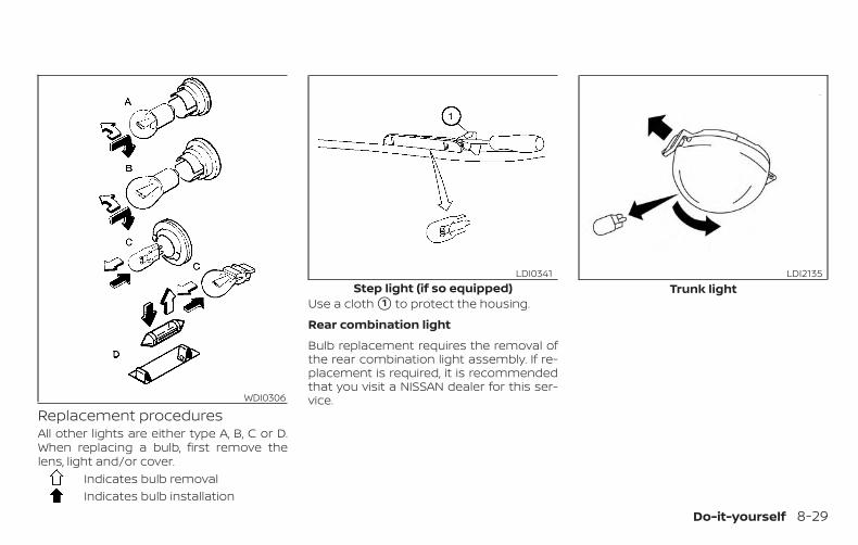
Replacement proceduresAll other lights are either type A, B, C or D.When replacing a bulb, first remove thelens, light and/or cover.
Indicates bulb removalIndicates bulb installation
Use a cloth �1 to protect the housing.
Rear combination light
Bulb replacement requires the removal ofthe rear combination light assembly. If re-placement is required, it is recommendedthat you visit a NISSAN dealer for this ser-vice.WDI0306
Step light (if so equipped)LDI0341
Trunk lightLDI2135
Do-it-yourself 8-29
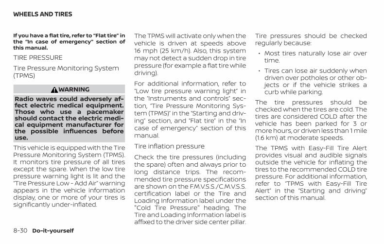
If you have a flat tire, refer to “Flat tire” inthe “In case of emergency” section ofthis manual.
TIRE PRESSURETire Pressure Monitoring System(TPMS)
WARNINGRadio waves could adversely af-fect electric medical equipment.Those who use a pacemakershould contact the electric medi-cal equipment manufacturer forthe possible influences beforeuse.This vehicle is equipped with the TirePressure Monitoring System (TPMS).It monitors tire pressure of all tiresexcept the spare. When the low tirepressure warning light is lit and the“Tire Pressure Low - Add Air” warningappears in the vehicle informationdisplay, one or more of your tires issignificantly under-inflated.
The TPMS will activate only when thevehicle is driven at speeds above16 mph (25 km/h). Also, this systemmay not detect a sudden drop in tirepressure (for example a flat tire whiledriving).
For additional information, refer to“Low tire pressure warning light” inthe “Instruments and controls” sec-tion, “Tire Pressure Monitoring Sys-tem (TPMS)” in the “Starting and driv-ing” section, and “Flat tire” in the “Incase of emergency” section of thismanual.
Tire inflation pressureCheck the tire pressures (includingthe spare) often and always prior tolong distance trips. The recom-mended tire pressure specificationsare shown on the F.M.V.S.S./C.M.V.S.S.certification label or the Tire andLoading Information label under the"Cold Tire Pressure" heading. TheTire and Loading Information label isaffixed to the driver side center pillar.
Tire pressures should be checkedregularly because:∙ Most tires naturally lose air over
time.∙ Tires can lose air suddenly when
driven over potholes or other ob-jects or if the vehicle strikes acurb while parking.
The tire pressures should bechecked when the tires are cold. Thetires are considered COLD after thevehicle has been parked for 3 ormore hours, or driven less than 1 mile(1.6 km) at moderate speeds.The TPMS with Easy-Fill Tire Alertprovides visual and audible signalsoutside the vehicle for inflating thetires to the recommended COLD tirepressure. For additional information,refer to “TPMS with Easy-Fill TireAlert” in the “Starting and driving”section of this manual.
WHEELS AND TIRES
8-30 Do-it-yourself
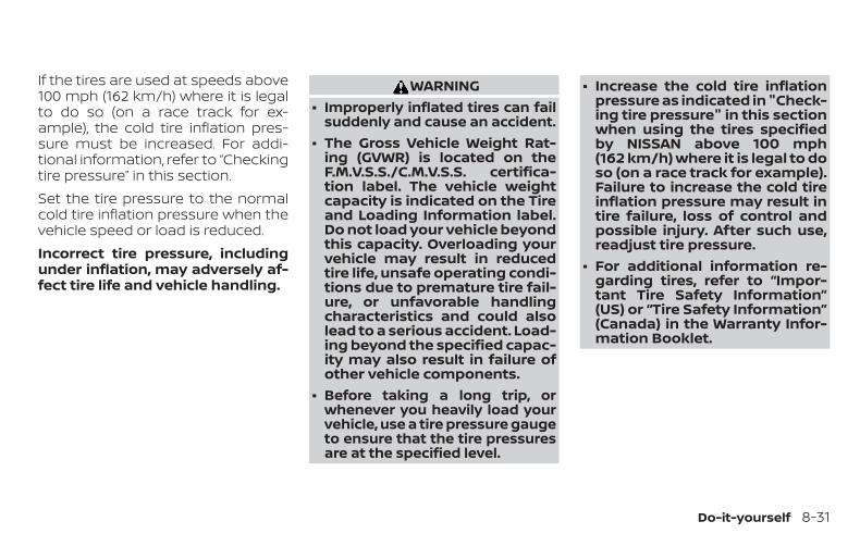
If the tires are used at speeds above100 mph (162 km/h) where it is legalto do so (on a race track for ex-ample), the cold tire inflation pres-sure must be increased. For addi-tional information, refer to “Checkingtire pressure” in this section.Set the tire pressure to the normalcold tire inflation pressure when thevehicle speed or load is reduced.Incorrect tire pressure, includingunder inflation, may adversely af-fect tire life and vehicle handling.
WARNING∙ Improperly inflated tires can fail
suddenly and cause an accident.∙ The Gross Vehicle Weight Rat-
ing (GVWR) is located on theF.M.V.S.S./C.M.V.S.S. certifica-tion label. The vehicle weightcapacity is indicated on the Tireand Loading Information label.Do not load your vehicle beyondthis capacity. Overloading yourvehicle may result in reducedtire life, unsafe operating condi-tions due to premature tire fail-ure, or unfavorable handlingcharacteristics and could alsolead to a serious accident. Load-ing beyond the specified capac-ity may also result in failure ofother vehicle components.
∙ Before taking a long trip, orwhenever you heavily load yourvehicle, use a tire pressure gaugeto ensure that the tire pressuresare at the specified level.
∙ Increase the cold tire inflationpressure as indicated in "Check-ing tire pressure" in this sectionwhen using the tires specifiedby NISSAN above 100 mph(162 km/h) where it is legal to doso (on a race track for example).Failure to increase the cold tireinflation pressure may result intire failure, loss of control andpossible injury. After such use,readjust tire pressure.
∙ For additional information re-garding tires, refer to “Impor-tant Tire Safety Information”(US) or “Tire Safety Information”(Canada) in the Warranty Infor-mation Booklet.
Do-it-yourself 8-31
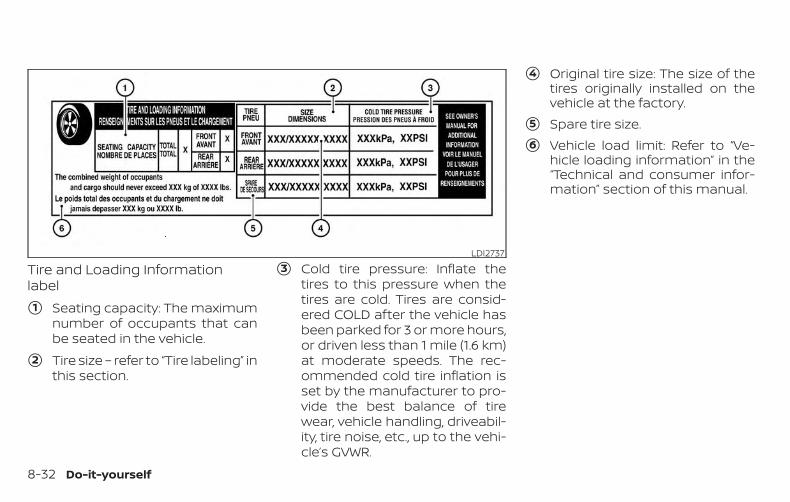
Tire and Loading Informationlabel
�1 Seating capacity: The maximumnumber of occupants that canbe seated in the vehicle.
�2 Tire size – refer to “Tire labeling” inthis section.
�3 Cold tire pressure: Inflate thetires to this pressure when thetires are cold. Tires are consid-ered COLD after the vehicle hasbeen parked for 3 or more hours,or driven less than 1 mile (1.6 km)at moderate speeds. The rec-ommended cold tire inflation isset by the manufacturer to pro-vide the best balance of tirewear, vehicle handling, driveabil-ity, tire noise, etc., up to the vehi-cle’s GVWR.
�4 Original tire size: The size of thetires originally installed on thevehicle at the factory.
�5 Spare tire size.
�6 Vehicle load limit: Refer to “Ve-hicle loading information” in the“Technical and consumer infor-mation” section of this manual.
LDI2737
8-32 Do-it-yourself
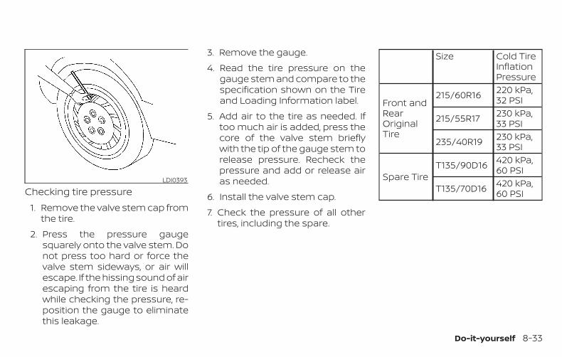
Checking tire pressure1. Remove the valve stem cap from
the tire.
2. Press the pressure gaugesquarely onto the valve stem. Donot press too hard or force thevalve stem sideways, or air willescape. If the hissing sound of airescaping from the tire is heardwhile checking the pressure, re-position the gauge to eliminatethis leakage.
3. Remove the gauge.
4. Read the tire pressure on thegauge stem and compare to thespecification shown on the Tireand Loading Information label.
5. Add air to the tire as needed. Iftoo much air is added, press thecore of the valve stem brieflywith the tip of the gauge stem torelease pressure. Recheck thepressure and add or release airas needed.
6. Install the valve stem cap.
7. Check the pressure of all othertires, including the spare.
Size Cold TireInflationPressure
Front andRearOriginalTire
215/60R16 220 kPa,32 PSI
215/55R17 230 kPa,33 PSI
235/40R19 230 kPa,33 PSI
Spare TireT135/90D16 420 kPa,
60 PSI
T135/70D16 420 kPa,60 PSI
LDI0393
Do-it-yourself 8-33
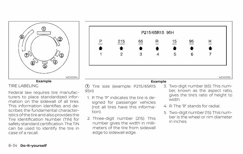
TIRE LABELINGFederal law requires tire manufac-turers to place standardized infor-mation on the sidewall of all tires.This information identifies and de-scribes the fundamental character-istics of the tire and also provides theTire Identification Number (TIN) forsafety standard certification. The TINcan be used to identify the tire incase of a recall.
�1 Tire size (example: P215/65R1595H)
1. P: The “P” indicates the tire is de-signed for passenger vehicles(not all tires have this informa-tion).
2. Three-digit number (215): Thisnumber gives the width in milli-meters of the tire from sidewalledge to sidewall edge.
3. Two-digit number (65): This num-ber, known as the aspect ratio,gives the tire’s ratio of height towidth.
4. R: The “R” stands for radial.5. Two-digit number (15): This num-
ber is the wheel or rim diameterin inches.
ExampleWDI0394
ExampleWDI0395
8-34 Do-it-yourself
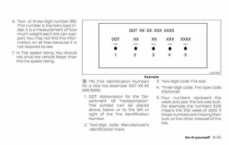
6. Two- or three-digit number (95):This number is the tire’s load in-dex. It is a measurement of howmuch weight each tire can sup-port. You may not find this infor-mation on all tires because it isnot required by law.
7. H: Tire speed rating. You shouldnot drive the vehicle faster thanthe tire speed rating.
�2 TIN (Tire Identification Number)for a new tire (example: DOT XX XXXXX XXXX)
1. DOT: Abbreviation for the “De-partment Of Transportation”.The symbol can be placedabove, below or to the left orright of the Tire IdentificationNumber.
2. Two-digit code: Manufacturer’sidentification mark.
3. Two-digit code: Tire size.4. Three-digit code: Tire type code
(Optional).5. Four numbers represent the
week and year the tire was built.For example, the numbers 3103means the 31st week of 2003. Ifthese numbers are missing thenlook on the other sidewall of thetire.
ExampleLDI2786
Do-it-yourself 8-35
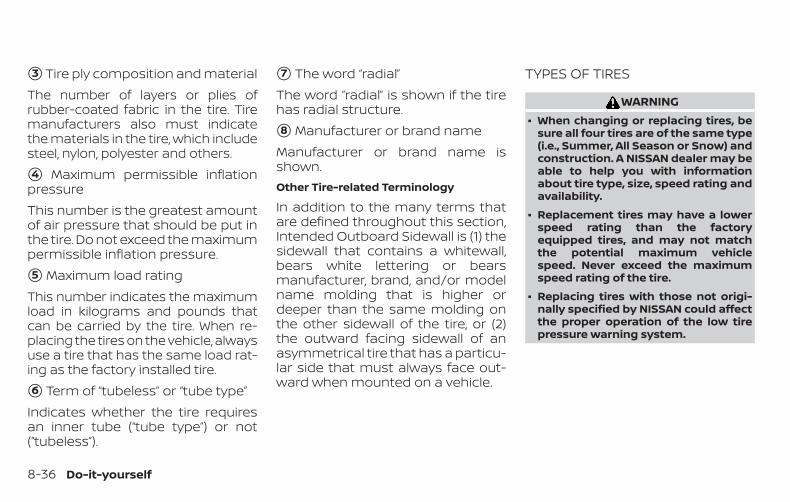
�3 Tire ply composition and materialThe number of layers or plies ofrubber-coated fabric in the tire. Tiremanufacturers also must indicatethe materials in the tire, which includesteel, nylon, polyester and others.
�4 Maximum permissible inflationpressureThis number is the greatest amountof air pressure that should be put inthe tire. Do not exceed the maximumpermissible inflation pressure.
�5 Maximum load ratingThis number indicates the maximumload in kilograms and pounds thatcan be carried by the tire. When re-placing the tires on the vehicle, alwaysuse a tire that has the same load rat-ing as the factory installed tire.
�6 Term of “tubeless” or “tube type”Indicates whether the tire requiresan inner tube (“tube type”) or not(“tubeless”).
�7 The word “radial”The word “radial” is shown if the tirehas radial structure.
�8 Manufacturer or brand nameManufacturer or brand name isshown.Other Tire-related Terminology
In addition to the many terms thatare defined throughout this section,Intended Outboard Sidewall is (1) thesidewall that contains a whitewall,bears white lettering or bearsmanufacturer, brand, and/or modelname molding that is higher ordeeper than the same molding onthe other sidewall of the tire, or (2)the outward facing sidewall of anasymmetrical tire that has a particu-lar side that must always face out-ward when mounted on a vehicle.
TYPES OF TIRES
WARNING∙ When changing or replacing tires, be
sure all four tires are of the same type(i.e., Summer, All Season or Snow) andconstruction. A NISSAN dealer may beable to help you with informationabout tire type, size, speed rating andavailability.
∙ Replacement tires may have a lowerspeed rating than the factoryequipped tires, and may not matchthe potential maximum vehiclespeed. Never exceed the maximumspeed rating of the tire.
∙ Replacing tires with those not origi-nally specified by NISSAN could affectthe proper operation of the low tirepressure warning system.
8-36 Do-it-yourself
∙ Always use tires of the same type,size, brand, construction and treadpattern on all four wheels. Failure todo so may result in a circumferencedifference between tires on the frontand rear axles which can cause theVehicle Dynamic Control (VDC) systemto malfunction resulting in personalinjury or death, excessive tire wearand may damage the transmissionand differential gears.
∙ For additional information regardingtires, refer to “Important Tire SafetyInformation” (US) or “Tire Safety Infor-mation” (Canada) in the Warranty In-formation Booklet.
All-Wheel Drive (AWD) models
CAUTION∙ ONLY use spare tires specified for the
AWD model.
If excessive tire wear is found, it is recom-mended that all four tires be replaced withtires of the same size, brand, constructionand tread pattern. The tire pressure andwheel alignment should also be checked
and corrected as necessary. It is recom-mended that you visit a NISSAN dealer forthis service.
All season tiresNISSAN specifies All Season tires on somemodels to provide good performance allyear, including snowy and icy road condi-tions. All Season tires are identified by ALLSEASON and/or M&S on the tire sidewall.Snow tires have better snow traction thanAll Season tires and may be more appropri-ate in some areas.
Summer tiresNISSAN specifies summer tires on somemodels to provide superior performanceon dry roads. Summer tire performance issubstantially reduced in snow and ice.Summer tires do not have the tire tractionrating “M&S” on the tire sidewall.
If you plan to operate your vehicle in snowyor icy conditions, NISSAN recommends theuse of SNOW tires or ALL SEASON tires on allfour wheels.
Snow tiresIf snow tires are needed, it is necessary toselect tires equivalent in size and load rat-ing to the original equipment tires. If you do
not, it can adversely affect the safety andhandling of your vehicle.
Generally, snow tires have lower speed rat-ings than factory equipped tires and maynot match the potential maximum vehiclespeed. Never exceed the maximum speedrating of the tire.
If you install snow tires, they must be thesame size, brand, construction and treadpattern on all four wheels.
For additional traction on icy roads, stud-ded tires may be used. However, some U.S.states and Canadian provinces prohibittheir use. Check local, state and provinciallaws before installing studded tires. Skidand traction capabilities of studded snowtires on wet or dry surfaces may be poorerthan that of non-studded snow tires.
TIRE CHAINS
CAUTIONOnly certain SAE class “S” tire chains canbe used on this vehicle. Using the wrongClass “S” chains on this vehicle willcause damage to the vehicle. If you planto use tire chains/cables, you shoulduse a tire chain that meets the mini-mum clearances for your vehicle.
Do-it-yourself 8-37
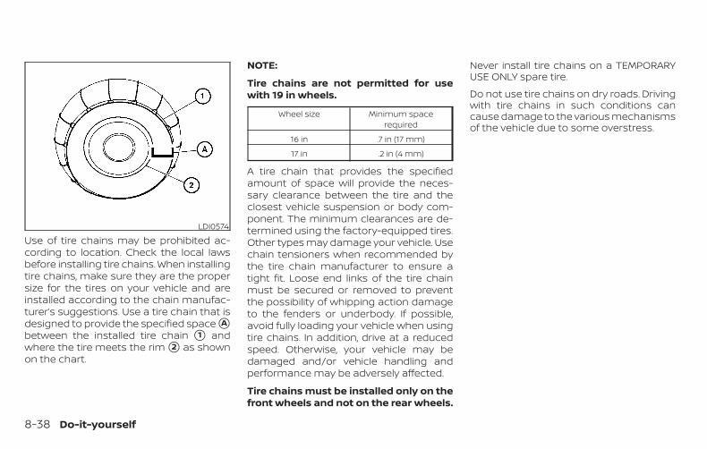
Use of tire chains may be prohibited ac-cording to location. Check the local lawsbefore installing tire chains. When installingtire chains, make sure they are the propersize for the tires on your vehicle and areinstalled according to the chain manufac-turer’s suggestions. Use a tire chain that isdesigned to provide the specified space �Abetween the installed tire chain �1 andwhere the tire meets the rim �2 as shownon the chart.
NOTE:
Tire chains are not permitted for usewith 19 in wheels.
Wheel size Minimum spacerequired
16 in .7 in (17 mm)
17 in .2 in (4 mm)
A tire chain that provides the specifiedamount of space will provide the neces-sary clearance between the tire and theclosest vehicle suspension or body com-ponent. The minimum clearances are de-termined using the factory-equipped tires.Other types may damage your vehicle. Usechain tensioners when recommended bythe tire chain manufacturer to ensure atight fit. Loose end links of the tire chainmust be secured or removed to preventthe possibility of whipping action damageto the fenders or underbody. If possible,avoid fully loading your vehicle when usingtire chains. In addition, drive at a reducedspeed. Otherwise, your vehicle may bedamaged and/or vehicle handling andperformance may be adversely affected.
Tire chains must be installed only on thefront wheels and not on the rear wheels.
Never install tire chains on a TEMPORARYUSE ONLY spare tire.
Do not use tire chains on dry roads. Drivingwith tire chains in such conditions cancause damage to the various mechanismsof the vehicle due to some overstress.
LDI0574
8-38 Do-it-yourself
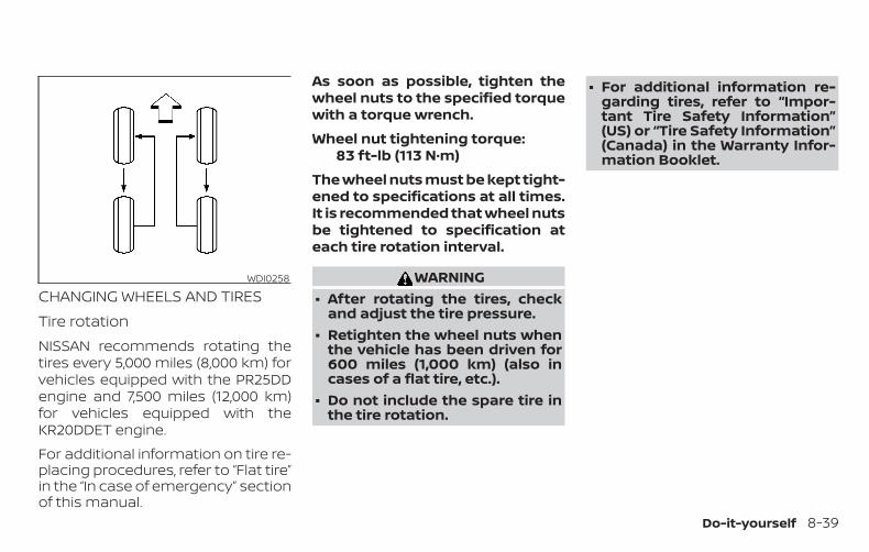
CHANGING WHEELS AND TIRESTire rotationNISSAN recommends rotating thetires every 5,000 miles (8,000 km) forvehicles equipped with the PR25DDengine and 7,500 miles (12,000 km)for vehicles equipped with theKR20DDET engine.
For additional information on tire re-placing procedures, refer to “Flat tire”in the “In case of emergency” sectionof this manual.
As soon as possible, tighten thewheel nuts to the specified torquewith a torque wrench.
Wheel nut tightening torque:83 ft-lb (113 N·m)
The wheel nuts must be kept tight-ened to specifications at all times.It is recommended that wheel nutsbe tightened to specification ateach tire rotation interval.
WARNING∙ After rotating the tires, check
and adjust the tire pressure.∙ Retighten the wheel nuts when
the vehicle has been driven for600 miles (1,000 km) (also incases of a flat tire, etc.).
∙ Do not include the spare tire inthe tire rotation.
∙ For additional information re-garding tires, refer to “Impor-tant Tire Safety Information”(US) or “Tire Safety Information”(Canada) in the Warranty Infor-mation Booklet.
WDI0258
Do-it-yourself 8-39
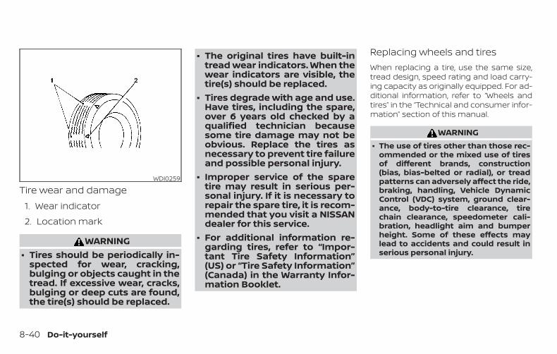
Tire wear and damage1. Wear indicator
2. Location mark
WARNING∙ Tires should be periodically in-
spected for wear, cracking,bulging or objects caught in thetread. If excessive wear, cracks,bulging or deep cuts are found,the tire(s) should be replaced.
∙ The original tires have built-intread wear indicators. When thewear indicators are visible, thetire(s) should be replaced.
∙ Tires degrade with age and use.Have tires, including the spare,over 6 years old checked by aqualified technician becausesome tire damage may not beobvious. Replace the tires asnecessary to prevent tire failureand possible personal injury.
∙ Improper service of the sparetire may result in serious per-sonal injury. If it is necessary torepair the spare tire, it is recom-mended that you visit a NISSANdealer for this service.
∙ For additional information re-garding tires, refer to “Impor-tant Tire Safety Information”(US) or “Tire Safety Information”(Canada) in the Warranty Infor-mation Booklet.
Replacing wheels and tiresWhen replacing a tire, use the same size,tread design, speed rating and load carry-ing capacity as originally equipped. For ad-ditional information, refer to “Wheels andtires” in the “Technical and consumer infor-mation” section of this manual.
WARNING∙ The use of tires other than those rec-
ommended or the mixed use of tiresof different brands, construction(bias, bias-belted or radial), or treadpatterns can adversely affect the ride,braking, handling, Vehicle DynamicControl (VDC) system, ground clear-ance, body-to-tire clearance, tirechain clearance, speedometer cali-bration, headlight aim and bumperheight. Some of these effects maylead to accidents and could result inserious personal injury.
WDI0259
8-40 Do-it-yourself
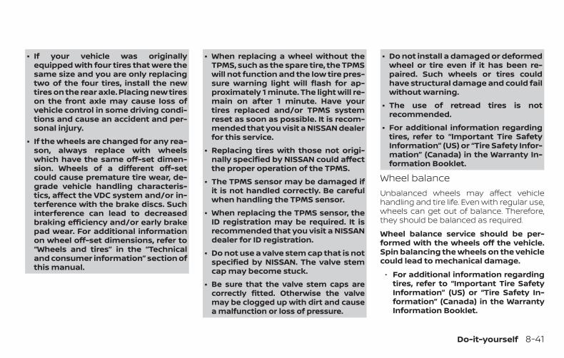
∙ If your vehicle was originallyequipped with four tires that were thesame size and you are only replacingtwo of the four tires, install the newtires on the rear axle. Placing new tireson the front axle may cause loss ofvehicle control in some driving condi-tions and cause an accident and per-sonal injury.
∙ If the wheels are changed for any rea-son, always replace with wheelswhich have the same off-set dimen-sion. Wheels of a different off-setcould cause premature tire wear, de-grade vehicle handling characteris-tics, affect the VDC system and/or in-terference with the brake discs. Suchinterference can lead to decreasedbraking efficiency and/or early brakepad wear. For additional informationon wheel off-set dimensions, refer to“Wheels and tires” in the “Technicaland consumer information” section ofthis manual.
∙ When replacing a wheel without theTPMS, such as the spare tire, the TPMSwill not function and the low tire pres-sure warning light will flash for ap-proximately 1 minute. The light will re-main on after 1 minute. Have yourtires replaced and/or TPMS systemreset as soon as possible. It is recom-mended that you visit a NISSAN dealerfor this service.
∙ Replacing tires with those not origi-nally specified by NISSAN could affectthe proper operation of the TPMS.
∙ The TPMS sensor may be damaged ifit is not handled correctly. Be carefulwhen handling the TPMS sensor.
∙ When replacing the TPMS sensor, theID registration may be required. It isrecommended that you visit a NISSANdealer for ID registration.
∙ Do not use a valve stem cap that is notspecified by NISSAN. The valve stemcap may become stuck.
∙ Be sure that the valve stem caps arecorrectly fitted. Otherwise the valvemay be clogged up with dirt and causea malfunction or loss of pressure.
∙ Do not install a damaged or deformedwheel or tire even if it has been re-paired. Such wheels or tires couldhave structural damage and could failwithout warning.
∙ The use of retread tires is notrecommended.
∙ For additional information regardingtires, refer to “Important Tire SafetyInformation” (US) or “Tire Safety Infor-mation” (Canada) in the Warranty In-formation Booklet.
Wheel balanceUnbalanced wheels may affect vehiclehandling and tire life. Even with regular use,wheels can get out of balance. Therefore,they should be balanced as required.
Wheel balance service should be per-formed with the wheels off the vehicle.Spin balancing the wheels on the vehiclecould lead to mechanical damage.
∙ For additional information regardingtires, refer to “Important Tire SafetyInformation” (US) or “Tire Safety In-formation” (Canada) in the WarrantyInformation Booklet.
Do-it-yourself 8-41
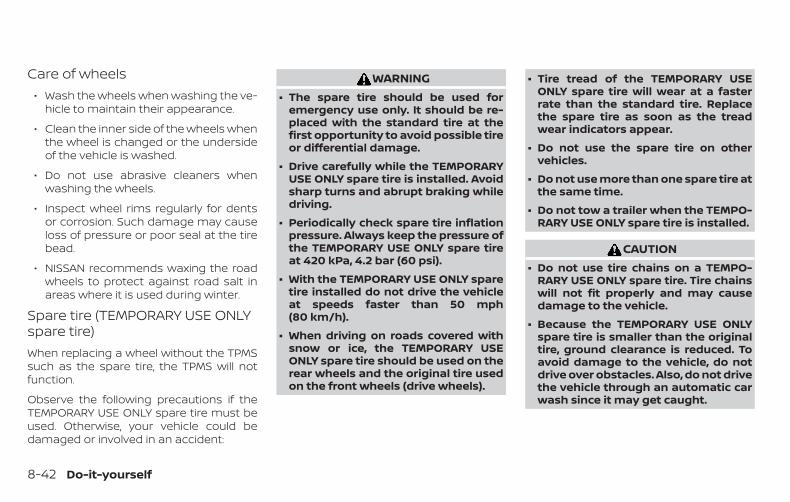
Care of wheels∙ Wash the wheels when washing the ve-
hicle to maintain their appearance.
∙ Clean the inner side of the wheels whenthe wheel is changed or the undersideof the vehicle is washed.
∙ Do not use abrasive cleaners whenwashing the wheels.
∙ Inspect wheel rims regularly for dentsor corrosion. Such damage may causeloss of pressure or poor seal at the tirebead.
∙ NISSAN recommends waxing the roadwheels to protect against road salt inareas where it is used during winter.
Spare tire (TEMPORARY USE ONLYspare tire)When replacing a wheel without the TPMSsuch as the spare tire, the TPMS will notfunction.
Observe the following precautions if theTEMPORARY USE ONLY spare tire must beused. Otherwise, your vehicle could bedamaged or involved in an accident:
WARNING∙ The spare tire should be used for
emergency use only. It should be re-placed with the standard tire at thefirst opportunity to avoid possible tireor differential damage.
∙ Drive carefully while the TEMPORARYUSE ONLY spare tire is installed. Avoidsharp turns and abrupt braking whiledriving.
∙ Periodically check spare tire inflationpressure. Always keep the pressure ofthe TEMPORARY USE ONLY spare tireat 420 kPa, 4.2 bar (60 psi).
∙ With the TEMPORARY USE ONLY sparetire installed do not drive the vehicleat speeds faster than 50 mph(80 km/h).
∙ When driving on roads covered withsnow or ice, the TEMPORARY USEONLY spare tire should be used on therear wheels and the original tire usedon the front wheels (drive wheels).
∙ Tire tread of the TEMPORARY USEONLY spare tire will wear at a fasterrate than the standard tire. Replacethe spare tire as soon as the treadwear indicators appear.
∙ Do not use the spare tire on othervehicles.
∙ Do not use more than one spare tire atthe same time.
∙ Do not tow a trailer when the TEMPO-RARY USE ONLY spare tire is installed.
CAUTION∙ Do not use tire chains on a TEMPO-
RARY USE ONLY spare tire. Tire chainswill not fit properly and may causedamage to the vehicle.
∙ Because the TEMPORARY USE ONLYspare tire is smaller than the originaltire, ground clearance is reduced. Toavoid damage to the vehicle, do notdrive over obstacles. Also, do not drivethe vehicle through an automatic carwash since it may get caught.
8-42 Do-it-yourself
9 Maintenance and schedules
Maintenance requirements. . . . . . . . . . . . . . . . . . . . . . 9-2General maintenance . . . . . . . . . . . . . . . . . . . . . . . . 9-2Scheduled maintenance . . . . . . . . . . . . . . . . . . . . . 9-2Where to go for service . . . . . . . . . . . . . . . . . . . . . . . 9-2
General maintenance . . . . . . . . . . . . . . . . . . . . . . . . . . . 9-3Explanation of general maintenanceitems. . . . . . . . . . . . . . . . . . . . . . . . . . . . . . . . . . . . . . . . . 9-3
Explanation of scheduled maintenance items . . . 9-5Emission control system maintenance:. . . . . . . 9-6Chassis and body maintenance:. . . . . . . . . . . . . . 9-6
Maintenance schedules . . . . . . . . . . . . . . . . . . . . . . . . . 9-7Additional maintenance items forsevere operating conditions . . . . . . . . . . . . . . . . . . 9-7Oil control system . . . . . . . . . . . . . . . . . . . . . . . . . . . . 9-7
Standard maintenance . . . . . . . . . . . . . . . . . . . . . . . . . 9-10PR25DD Engine model . . . . . . . . . . . . . . . . . . . . . . . 9-10
Emission control system maintenance . . . . . . 9-10Chassis & body maintenance. . . . . . . . . . . . . . . . 9-12
Maintenance under severe operatingconditions. . . . . . . . . . . . . . . . . . . . . . . . . . . . . . . . . . . . . . 9-14
Severe driving conditions . . . . . . . . . . . . . . . . . . . . 9-14Standard maintenance . . . . . . . . . . . . . . . . . . . . . . . . . 9-15
KR20DDET Engine model . . . . . . . . . . . . . . . . . . . . 9-15Emission control system maintenance . . . . . . 9-15Chassis & body maintenance. . . . . . . . . . . . . . . . 9-17
Maintenance under severe operatingconditions. . . . . . . . . . . . . . . . . . . . . . . . . . . . . . . . . . . . . . 9-19
Severe driving conditions . . . . . . . . . . . . . . . . . . . . 9-19Maintenance log . . . . . . . . . . . . . . . . . . . . . . . . . . . . . . . 9-20
PR25DD Engine model . . . . . . . . . . . . . . . . . . . . . . . 9-20KR20DDET Engine model . . . . . . . . . . . . . . . . . . . . 9-23
Some day-to-day and regular mainte-nance is essential to maintain your vehiclegood mechanical condition, as well as itsemissions and engine performance.
It is the owner’s responsibility to make surethat the scheduled maintenance, as well asgeneral maintenance, is performed.
As the vehicle owner, you are the only onewho can ensure that your vehicle receivesproper maintenance. You are a vital link inthe maintenance chain.
GENERAL MAINTENANCEGeneral maintenance includes those itemswhich should be checked during normalday-to-day operation. They are essentialfor proper vehicle operation. It is your re-sponsibility to perform these proceduresregularly as prescribed.
Performing general maintenance checksrequires minimal mechanical skill and onlya few general automotive tools.
These checks or inspections can be doneby yourself, a qualified technician or, if youprefer, a NISSAN dealer.
SCHEDULED MAINTENANCEThe maintenance items listed in this sec-tion are required to be serviced at regularintervals. However under severe drivingconditions, additional or more frequentmaintenance will be required.
WHERE TO GO FOR SERVICEIf maintenance service is required or yourvehicle appears to malfunction, have thesystems checked and serviced. It is recom-mended that you visit a NISSAN dealer forthis service.
NISSAN technicians are well-trained spe-cialists and are kept up-to-date with thelatest service information through techni-cal bulletins, service tips and training pro-grams. They are completely qualified towork on NISSAN vehicles before work be-gins.
If your vehicle is involved in a collision, it isrecommended that you ask your NISSANdealer where the nearest NISSAN CertifiedCollision Center is located, or go tohttp://collision.nissanusa.com.
You can be confident that a NISSAN deal-er’s service department can perform theservice needed to meet the maintenancerequirements on your vehicle.
MAINTENANCE REQUIREMENTS
9-2 Maintenance and schedules
During the normal day-to-day operation ofthe vehicle, general maintenance shouldbe performed regularly as prescribed inthis section. If you detect any unusualsounds, vibrations or smells, be sure tocheck for the cause or have it checkedpromptly. In addition, it is recommendedthat you visit a NISSAN dealer if you thinkthat repairs are required.
When performing any checks or mainte-nance work, closely observe the “Mainte-nance precautions” in the “Do-it-yourself ”section of this manual.
EXPLANATION OF GENERALMAINTENANCE ITEMSAdditional information on the followingitems with “ * ” is found in the “Do-it-yourself” section of this manual.
Outside the vehicleThe maintenance items listed here shouldbe performed from time to time, unlessotherwise specified.
Doors and engine hood: Check that thedoors and engine hood operate properly.Also ensure that all latches lock securely. Lu-bricate hinges, latches, latch pins, rollers andlinks if necessary. Make sure that the sec-
ondary latch keeps the hood from openingwhen the primary latch is released.
When driving in areas using road salt orother corrosive materials, check lubrica-tion frequently.
Lights*: Clean the headlights on a regularbasis. Make sure that the headlights, stoplights, tail lights, turn signal lights, and otherlights are all operating properly and in-stalled securely. Also check headlight aim.
Road wheel nuts (lug nuts)*: When check-ing the tires, make sure no wheel nuts aremissing, and check for any loose wheelnuts. Tighten if necessary.
Tire rotation*: PR25DD Engine model; Tiresshould be rotated every 5,000 miles(8,000 km).KR25DDET Engine Model; Tires should berotated every 7,500 miles (12,000 km).
Tires*: Check the pressure with a gaugeoften and always prior to long distancetrips. If necessary, adjust the pressure in alltires, including the spare, to the pressurespecified. Check carefully for damage, cutsor excessive wear.
Tire Pressure Monitoring System (TPMS)transmitter components: Replace the
TPMS transmitter grommet seal, valve coreand cap when the tires are replaced due towear or age.
Wheel alignment and balance: If the ve-hicle should pull to either side while drivingon a straight and level road, or if you detectuneven or abnormal tire wear, there maybe a need for wheel alignment. If the steer-ing wheel or seat vibrates at normal high-way speeds, wheel balancing may beneeded.
For additional information regarding tires,refer to “Important Tire Safety Information”(US) or “Tire Safety Information” (Canada) inthe Warranty Information Booklet.
Windshield: Clean the windshield on aregular basis. Check the windshield at leastevery six months for cracks or other dam-age. Have a damaged windshield repairedby a qualified repair facility. It is recom-mended that you have a damaged wind-shield repaired by a NISSAN dealer, or aNISSAN Certified Collision Center. To locatea collision center in your area, refer tohttp://collision.nissanusa.com.
Windshield wiper blades*: Check forcracks or wear if they do not wipe properly.
GENERAL MAINTENANCE
Maintenance and schedules 9-3
Inside the vehicleThe maintenance items listed here shouldbe checked on a regular basis, such aswhen performing scheduled maintenance,cleaning the vehicle, etc.
Accelerator pedal: Check the pedal forsmooth operation and make sure thepedal does not catch or require uneveneffort. Keep the floor mat away from thepedal.
Brake pedal: Check the pedal for smoothoperation. If the brake pedal suddenly goesdown further than normal, the pedal feelsspongy or the vehicle seems to take longerto stop, have your vehicle checked imme-diately. It is recommended that you visit aNISSAN dealer for this service. Keep thefloor mat away from the pedal.
Brakes: Check that the brakes do not pullthe vehicle to one side when applied.
Continuously Variable Transmission(CVT) P (Park) position mechanism: On afairly steep hill check that the vehicle is heldsecurely with the shift lever in the P (Park)position without applying any brakes.
Parking brake: Check the parking brakeoperation regularly. The vehicle should besecurely held on a fairly steep hill with only
the parking brake applied. If the parkingbrake needs adjustment, it is recom-mended that you visit a NISSAN dealer forthis service.
Seats: Check seat position controls suchas seat adjusters, seatback recliner, etc., toensure they operate smoothly and alllatches lock securely in every position.Check that the head restraints/headrestsmove up and down smoothly and the locks(if so equipped) hold securely in all latchedpositions.
Seat belts: Check that all parts of the seatbelt system (for example, buckles, anchors,adjusters and retractors) operate properlyand smoothly, and are installed securely.Check the belt webbing for cuts, fraying,wear or damage.
Steering wheel: Check for changes in thesteering system, such as excessive freeplay, hard steering or strange noises.
Warning lights and chimes: Make sure allwarning lights and chimes are operatingproperly.
Windshield defroster: Check that the aircomes out of the defroster outlets properlyand in sufficient quantity when operatingthe heater or air conditioner.
Windshield wiper and washer*: Checkthat the wipers and washer operate prop-erly and that the wipers do not streak.
Under the hood and vehicleThe maintenance items listed here shouldbe checked periodically (for example, eachtime you check the engine oil or refuel).
Battery*: This vehicle is equipped with asealed maintenance free battery. It is rec-ommended that you visit a NISSAN dealerfor service.
NOTE:
Care should be taken to avoid situationsthat can lead to potential battery dis-charge and potential no-start conditionssuch as:
1. Installation or extended use of elec-tronic accessories that consume bat-tery power when the engine is notrunning (Phone chargers, GPS, DVDplayers, etc.).
2. Vehicle is not driven regularly and/oronly driven short distances.
In these cases, the battery may need tobe charged to maintain battery health.
9-4 Maintenance and schedules
Brake fluid level*: Make sure that the brakefluid level is between the MAX and MIN lineson the reservoir.
Engine coolant level*: Check the coolantlevel when the engine is cold.
Engine drive belts*: Make sure the drivebelts are not frayed, worn, cracked or oily.
Engine oil level*: Check the level afterparking the vehicle on a level spot andturning off the engine. Wait more than15 minutes for the oil to drain back into theoil pan.
Exhaust system: Make sure there are noloose supports, cracks or holes. If thesound of the exhaust seems unusual orthere is a smell of exhaust fumes, immedi-ately have the exhaust system inspected. Itis recommended that you visit a NISSANdealer for this service. For additional infor-mation, refer to “Exhaust gas (carbon mon-oxide)” in the “Starting and driving” sectionof this manual.
Fluid leaks: Check under the vehicle forfuel, oil, water or other fluid leaks after thevehicle has been parked for a while. Waterdripping from the air conditioner after use
is normal. If you should notice any leaks or iffuel fumes are evident, check for the causeand have it corrected immediately.
Radiator and hoses: Check the front of theradiator and clean off any dirt, insects,leaves, etc., that may have accumulated.Make sure the hoses have no cracks, defor-mation, rot or loose connections.
Underbody: The underbody is frequentlyexposed to corrosive substances such asthose used on icy roads or to control dust. Itis very important to remove these sub-stances, otherwise rust may form on thefloor pan, frame, fuel lines and around theexhaust system. At the end of winter, theunderbody should be thoroughly flushedwith plain water, being careful to cleanthose areas where mud and dirt may accu-mulate. For additional information, refer tothe “Appearance and care” section of thismanual.
Windshield-washer fluid*: Check thatthere is adequate fluid in the reservoir.
The following descriptions are provided togive you a better understanding of thescheduled maintenance items that shouldbe regularly checked or replaced. Themaintenance schedule indicates at whichmileage/time intervals each item requiresservice.
In addition to scheduled maintenance,your vehicle requires that some items bechecked during normal day-to-day opera-tion. For additional information, refer to“General maintenance” in this section.
Items marked with “*” are recommendedby NISSAN for reliable vehicle operation.You are not required to perform mainte-nance on these items in order to maintainthe warranties which come with yourNISSAN. Other maintenance items and in-tervals are required.
When applicable, additional informationcan be found in the “Do-it-yourself ” sectionof this manual.
EXPLANATION OF SCHEDULEDMAINTENANCE ITEMS
Maintenance and schedules 9-5
NOTE:
NISSAN does not advocate the use ofnon-OEM approved aftermarket flush-ing systems and strongly advisesagainst performing these services on aNISSAN product. Many of the aftermar-ket flushing systems use non-OEM ap-proved chemicals or solvents, the use ofwhich has not been validated by NISSAN.
For recommended fuel, lubricants, fluids,grease, and refrigerant, refer to “Recom-mended fluids/lubricants and capaci-ties” in the “Technical and consumer in-formation” section of this manual.
EMISSION CONTROL SYSTEMMAINTENANCE:Drive belts*: Check engine drive belts forwear, fraying or cracking and for propertension. Replace any damaged drive belts.
Engine air filter: Replace at specified inter-vals. When driving for prolonged periods industy conditions, check/replace the filtermore frequently.
Engine coolant*: Replace coolant at thespecified interval. When adding or replac-ing coolant, be sure to use only GenuineNISSAN Long Life Antifreeze/Coolant (blue)
or equivalent with the proper mixture. (Foradditional information on the proper mix-ture for your area, refer to “Engine coolingsystem” in the “Do-it-yourself ” section ofthis manual.)
NOTE: Mixing any other type of coolantor the use of non-distilled water may re-duce the recommended service intervalof the coolant.
Engine oil and oil filter: Replace engine oiland oil filter at the specified intervals. Forrecommended oil grade and viscosity referto “Recommended fluids/lubricants andcapacities” in the “Technical and consumerinformation” section of this manual.
Engine valve clearance*: Inspect only ifvalve noise increases. Adjust valve clear-ance if necessary.
Evaporative emissions control vaporlines*: Check vapor lines for leaks or loose-ness. Tighten connections or replace partsas necessary.
Fuel filter: Periodic maintenance is not re-quired. (in-tank type filter)
Fuel lines*: Check the fuel hoses, pipingand connections for leaks, looseness, ordeterioration. Tighten connections or re-place parts as necessary.
Spark plugs: Replace at specified intervals.Install new plugs of the type as originallyequipped.
CHASSIS AND BODYMAINTENANCE:Brake lines and cables: Visually inspect forproper installation. Check for chafing,cracks, deterioration, and signs of leaking.Replace any deteriorated or damagedparts immediately.
Brake pads and rotors: Check for wear,deterioration and fluid leaks. Replace anydeteriorated or damaged parts immedi-ately.
Exhaust system: Visually inspect the ex-haust pipes, muffler and hangers for leaks,cracks, deterioration, and damage. Tightenconnections or replace parts as necessary.
Propeller shaft(s): Check for damage,looseness, and grease leakage. (AWD)
In-cabin microfilter: Replace at specifiedintervals. When driving for prolonged peri-ods in dusty conditions, replace the filtermore frequently.
9-6 Maintenance and schedules
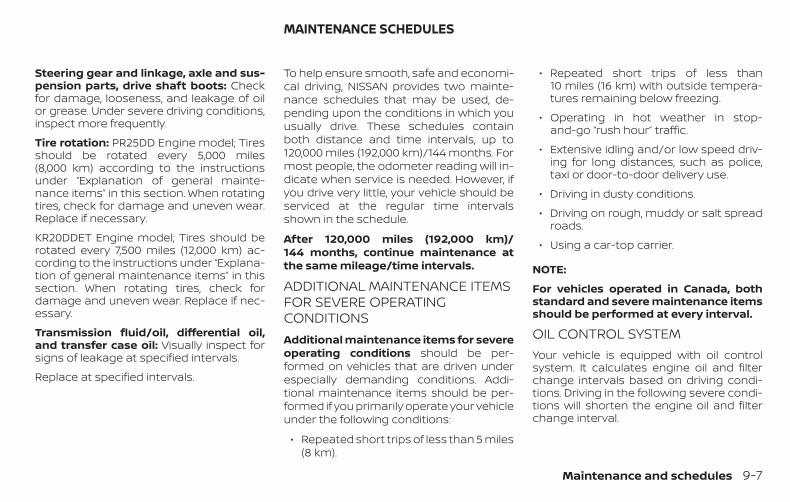
Steering gear and linkage, axle and sus-pension parts, drive shaft boots: Checkfor damage, looseness, and leakage of oilor grease. Under severe driving conditions,inspect more frequently.
Tire rotation: PR25DD Engine model; Tiresshould be rotated every 5,000 miles(8,000 km) according to the instructionsunder “Explanation of general mainte-nance items” in this section. When rotatingtires, check for damage and uneven wear.Replace if necessary.
KR20DDET Engine model; Tires should berotated every 7,500 miles (12,000 km) ac-cording to the instructions under “Explana-tion of general maintenance items” in thissection. When rotating tires, check fordamage and uneven wear. Replace if nec-essary.
Transmission fluid/oil, differential oil,and transfer case oil: Visually inspect forsigns of leakage at specified intervals.
Replace at specified intervals.
To help ensure smooth, safe and economi-cal driving, NISSAN provides two mainte-nance schedules that may be used, de-pending upon the conditions in which youusually drive. These schedules containboth distance and time intervals, up to120,000 miles (192,000 km)/144 months. Formost people, the odometer reading will in-dicate when service is needed. However, ifyou drive very little, your vehicle should beserviced at the regular time intervalsshown in the schedule.
After 120,000 miles (192,000 km)/144 months, continue maintenance atthe same mileage/time intervals.
ADDITIONAL MAINTENANCE ITEMSFOR SEVERE OPERATINGCONDITIONSAdditional maintenance items for severeoperating conditions should be per-formed on vehicles that are driven underespecially demanding conditions. Addi-tional maintenance items should be per-formed if you primarily operate your vehicleunder the following conditions:
∙ Repeated short trips of less than 5 miles(8 km).
∙ Repeated short trips of less than10 miles (16 km) with outside tempera-tures remaining below freezing.
∙ Operating in hot weather in stop-and-go “rush hour” traffic.
∙ Extensive idling and/or low speed driv-ing for long distances, such as police,taxi or door-to-door delivery use.
∙ Driving in dusty conditions.
∙ Driving on rough, muddy or salt spreadroads.
∙ Using a car-top carrier.
NOTE:
For vehicles operated in Canada, bothstandard and severe maintenance itemsshould be performed at every interval.
OIL CONTROL SYSTEMYour vehicle is equipped with oil controlsystem. It calculates engine oil and filterchange intervals based on driving condi-tions. Driving in the following severe condi-tions will shorten the engine oil and filterchange interval.
MAINTENANCE SCHEDULES
Maintenance and schedules 9-7
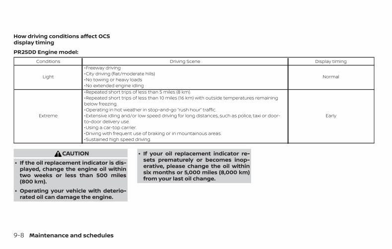
How driving conditions affect OCSdisplay timing
PR25DD Engine model:Conditions Driving Scene Display timing
Light
∙ Freeway driving∙ City driving (flat/moderate hills)∙ No towing or heavy loads∙ No extended engine idling
Normal
Extreme
∙ Repeated short trips of less than 5 miles (8 km).∙ Repeated short trips of less than 10 miles (16 km) with outside temperatures remainingbelow freezing.∙ Operating in hot weather in stop-and-go “rush hour” traffic.∙ Extensive idling and/or low speed driving for long distances, such as police, taxi or door-to-door delivery use.∙ Using a car-top carrier.∙ Driving with frequent use of braking or in mountainous areas.∙ Sustained high speed driving.
Early
CAUTION∙ If the oil replacement indicator is dis-
played, change the engine oil withintwo weeks or less than 500 miles(800 km).
∙ Operating your vehicle with deterio-rated oil can damage the engine.
∙ If your oil replacement indicator re-sets prematurely or becomes inop-erative, please change the oil withinsix months or 5,000 miles (8,000 km)from your last oil change.
9-8 Maintenance and schedules
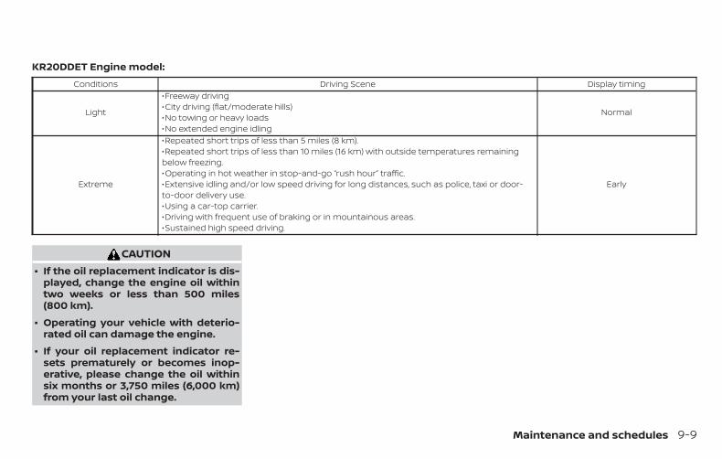
KR20DDET Engine model:Conditions Driving Scene Display timing
Light
∙ Freeway driving∙ City driving (flat/moderate hills)∙ No towing or heavy loads∙ No extended engine idling
Normal
Extreme
∙ Repeated short trips of less than 5 miles (8 km).∙ Repeated short trips of less than 10 miles (16 km) with outside temperatures remainingbelow freezing.∙ Operating in hot weather in stop-and-go “rush hour” traffic.∙ Extensive idling and/or low speed driving for long distances, such as police, taxi or door-to-door delivery use.∙ Using a car-top carrier.∙ Driving with frequent use of braking or in mountainous areas.∙ Sustained high speed driving.
Early
CAUTION∙ If the oil replacement indicator is dis-
played, change the engine oil withintwo weeks or less than 500 miles(800 km).
∙ Operating your vehicle with deterio-rated oil can damage the engine.
∙ If your oil replacement indicator re-sets prematurely or becomes inop-erative, please change the oil withinsix months or 3,750 miles (6,000 km)from your last oil change.
Maintenance and schedules 9-9
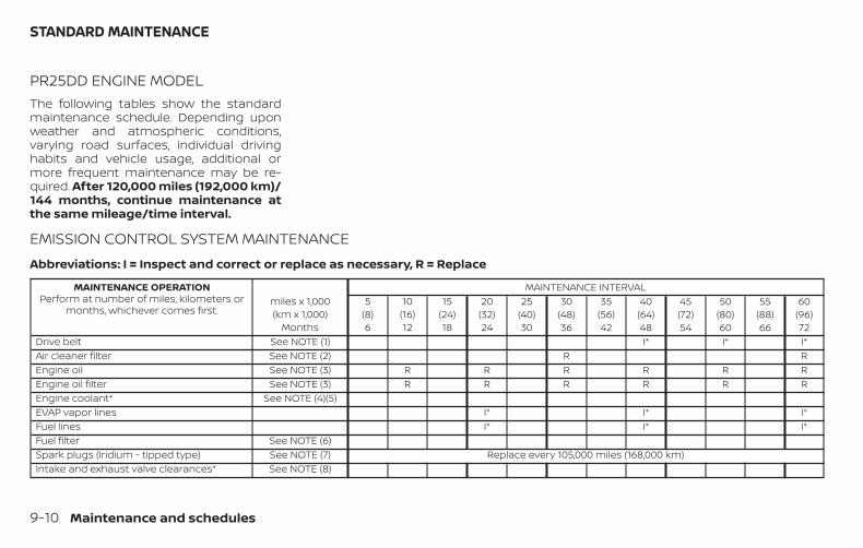
PR25DD ENGINE MODELThe following tables show the standardmaintenance schedule. Depending uponweather and atmospheric conditions,varying road surfaces, individual drivinghabits and vehicle usage, additional ormore frequent maintenance may be re-quired. After 120,000 miles (192,000 km)/144 months, continue maintenance atthe same mileage/time interval.
EMISSION CONTROL SYSTEM MAINTENANCEAbbreviations: I = Inspect and correct or replace as necessary, R = Replace
MAINTENANCE OPERATIONPerform at number of miles, kilometers or
months, whichever comes first.miles x 1,000(km x 1,000)
Months
MAINTENANCE INTERVAL5
(8)6
10(16)12
15(24)18
20(32)24
25(40)30
30(48)36
35(56)42
40(64)48
45(72)54
50(80)60
55(88)66
60(96)72
Drive belt See NOTE (1) I* I* I*Air cleaner filter See NOTE (2) R REngine oil See NOTE (3) R R R R R REngine oil filter See NOTE (3) R R R R R REngine coolant* See NOTE (4)(5)EVAP vapor lines I* I* I*Fuel lines I* I* I*Fuel filter See NOTE (6)Spark plugs (Iridium - tipped type) See NOTE (7) Replace every 105,000 miles (168,000 km)Intake and exhaust valve clearances* See NOTE (8)
STANDARD MAINTENANCE
9-10 Maintenance and schedules
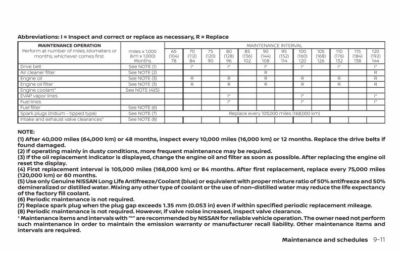
Abbreviations: I = Inspect and correct or replace as necessary, R = ReplaceMAINTENANCE OPERATION
Perform at number of miles, kilometers ormonths, whichever comes first.
miles x 1,000(km x 1,000)
Months
MAINTENANCE INTERVAL65
(104)78
70(112)84
75(120)90
80(128)96
85(136)102
90(144)108
95(152)114
100(160)120
105(168)126
110(176)132
115(184)138
120(192)144
Drive belt See NOTE (1) I* I* I* I* I* I*Air cleaner filter See NOTE (2) R REngine oil See NOTE (3) R R R R R REngine oil filter See NOTE (3) R R R R R REngine coolant* See NOTE (4)(5)EVAP vapor lines I* I* I*Fuel lines I* I* I*Fuel filter See NOTE (6)Spark plugs (Iridium - tipped type) See NOTE (7) Replace every 105,000 miles (168,000 km)Intake and exhaust valve clearances* See NOTE (8)
NOTE:(1) After 40,000 miles (64,000 km) or 48 months, inspect every 10,000 miles (16,000 km) or 12 months. Replace the drive belts iffound damaged.(2) If operating mainly in dusty conditions, more frequent maintenance may be required.(3) If the oil replacement indicator is displayed, change the engine oil and filter as soon as possible. After replacing the engine oilreset the display.(4) First replacement interval is 105,000 miles (168,000 km) or 84 months. After first replacement, replace every 75,000 miles(120,000 km) or 60 months.(5) Use only Genuine NISSAN Long Life Antifreeze/Coolant (blue) or equivalent with proper mixture ratio of 50% antifreeze and 50%demineralized or distilled water. Mixing any other type of coolant or the use of non-distilled water may reduce the life expectancyof the factory fill coolant.(6) Periodic maintenance is not required.(7) Replace spark plug when the plug gap exceeds 1.35 mm (0.053 in) even if within specified periodic replacement mileage.(8) Periodic maintenance is not required. However, if valve noise increased, inspect valve clearance.* Maintenance items and intervals with “*” are recommended by NISSAN for reliable vehicle operation. The owner need not performsuch maintenance in order to maintain the emission warranty or manufacturer recall liability. Other maintenance items andintervals are required.
Maintenance and schedules 9-11
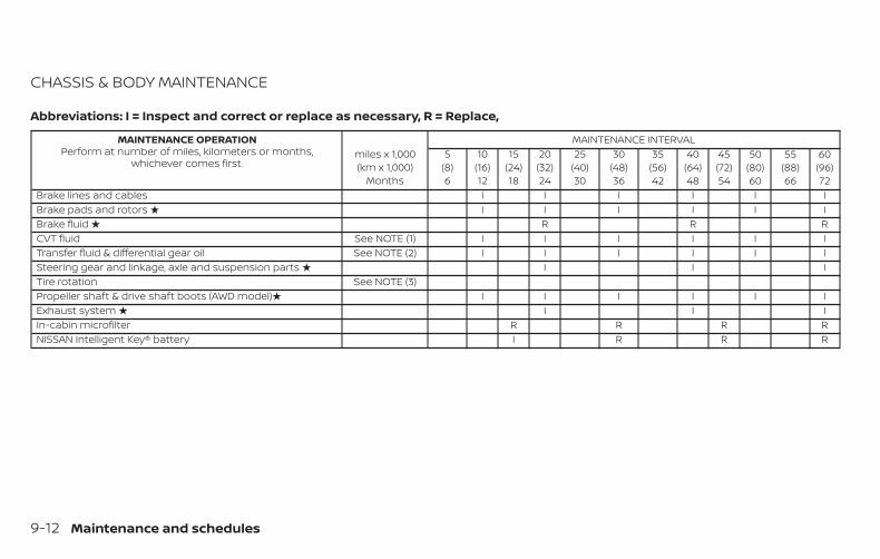
CHASSIS & BODY MAINTENANCE
Abbreviations: I = Inspect and correct or replace as necessary, R = Replace,
MAINTENANCE OPERATIONPerform at number of miles, kilometers or months,
whichever comes first.miles x 1,000(km x 1,000)
Months
MAINTENANCE INTERVAL5
(8)6
10(16)12
15(24)18
20(32)24
25(40)30
30(48)36
35(56)42
40(64)48
45(72)54
50(80)60
55(88)66
60(96)72
Brake lines and cables I I I I I IBrake pads and rotors � I I I I I IBrake fluid � R R RCVT fluid See NOTE (1) I I I I I ITransfer fluid & differential gear oil See NOTE (2) I I I I I ISteering gear and linkage, axle and suspension parts � I I ITire rotation See NOTE (3)Propeller shaft & drive shaft boots (AWD model)� I I I I I IExhaust system � I I IIn-cabin microfilter R R R RNISSAN Intelligent Key® battery I R R R
9-12 Maintenance and schedules
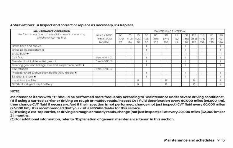
Abbreviations: I = Inspect and correct or replace as necessary, R = Replace,
MAINTENANCE OPERATIONPerform at number of miles, kilometers or months,
whichever comes first.miles x 1,000(km x 1,000)
Months
MAINTENANCE INTERVAL65
(104)78
70(112)84
75(120)90
80(128)96
85(136)102
90(144)108
95(152)114
100(160)120
105(168)126
110(176)132
115(184)138
120(192)144
Brake lines and cables I I I I I IBrake pads and rotors � I I I I I IBrake fluid � R R RCVT fluid See NOTE (1) I I I I I ITransfer fluid & differential gear oil See NOTE (2) I I I I I ISteering gear and linkage, axle and suspension parts � I I ITire rotation See NOTE (3)Propeller shaft & drive shaft boots (AWD model)� I I I I I IExhaust system � I I IIn-cabin microfilter R R R RNISSAN Intelligent Key® battery R R R R
NOTE:
Maintenance items with “�” should be performed more frequently according to “Maintenance under severe driving conditions”.(1) If using a car-top carrier or driving on rough or muddy roads, inspect CVT fluid deterioration every 60,000 miles (96,000 km),then change CVT fluid if necessary. And if the inspection is not performed, change (not just inspect) CVT fluid every 60,000 miles(96,000 km). It is recommended that you visit a NISSAN dealer for this service.(2) If using a car-top carrier, or driving on rough or muddy roads, change (not just inspect) oil at every 20,000 miles (32,000 km) or24 months.(3) For additional information, refer to “Explanation of general maintenance items” in this section.
Maintenance and schedules 9-13
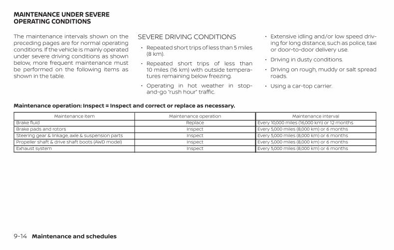
The maintenance intervals shown on thepreceding pages are for normal operatingconditions. If the vehicle is mainly operatedunder severe driving conditions as shownbelow, more frequent maintenance mustbe performed on the following items asshown in the table.
SEVERE DRIVING CONDITIONS∙ Repeated short trips of less than 5 miles
(8 km).
∙ Repeated short trips of less than10 miles (16 km) with outside tempera-tures remaining below freezing.
∙ Operating in hot weather in stop-and-go “rush hour” traffic.
∙ Extensive idling and/or low speed driv-ing for long distance, such as police, taxior door-to-door delivery use.
∙ Driving in dusty conditions.
∙ Driving on rough, muddy or salt spreadroads.
∙ Using a car-top carrier.
Maintenance operation: Inspect = Inspect and correct or replace as necessary.
Maintenance item Maintenance operation Maintenance intervalBrake fluid Replace Every 10,000 miles (16,000 km) or 12 monthsBrake pads and rotors Inspect Every 5,000 miles (8,000 km) or 6 monthsSteering gear & linkage, axle & suspension parts Inspect Every 5,000 miles (8,000 km) or 6 monthsPropeller shaft & drive shaft boots (AWD model) Inspect Every 5,000 miles (8,000 km) or 6 monthsExhaust system Inspect Every 5,000 miles (8,000 km) or 6 months
MAINTENANCE UNDER SEVEREOPERATING CONDITIONS
9-14 Maintenance and schedules
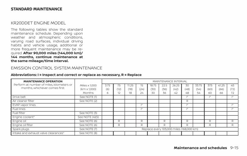
KR20DDET ENGINE MODELThe following tables show the standardmaintenance schedule. Depending uponweather and atmospheric conditions,varying road surfaces, individual drivinghabits and vehicle usage, additional ormore frequent maintenance may be re-quired. After 90,000 miles (144,000 km)/144 months, continue maintenance atthe same mileage/time interval.
EMISSION CONTROL SYSTEM MAINTENANCEAbbreviations: I = Inspect and correct or replace as necessary, R = Replace
MAINTENANCE OPERATIONPerform at number of miles, kilometers or
months, whichever comes first.Miles x 1,000(km x 1,000)
Months
MAINTENANCE INTERVAL3.75(6)6
7.5(12)12
11.25(18)18
15(24)24
18.75(30)30
22.5(36)36
26.25(42)42
30(48)48
33.75(54)54
37.5(60)60
41.25(66)66
45(72)72
Drive belt See NOTE (1) I* I* I*Air cleaner filter See NOTE (2) REVAP vapor lines I* I* I*Fuel lines I* I* I*Fuel filter See NOTE (3)Engine coolant* See NOTE (4)(5)Engine oil See NOTE (6) R R R R R REngine oil filter See NOTE (6) R R R R R RSpark plugs See NOTE (7) Replace every 105,000 miles (168,000 km)Intake and exhaust valve clearances* See NOTE (8)
STANDARD MAINTENANCE
Maintenance and schedules 9-15
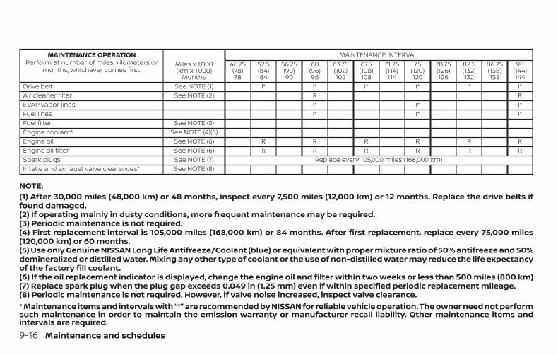
MAINTENANCE OPERATIONPerform at number of miles, kilometers or
months, whichever comes first.Miles x 1,000(km x 1,000)
Months
MAINTENANCE INTERVAL48.75(78)78
52.5(84)84
56.25(90)90
60(96)96
63.75(102)102
67.5(108)108
71.25(114)114
75(120)120
78.75(126)126
82.5(132)132
86.25(138)138
90(144)144
Drive belt See NOTE (1) I* I* I* I* I* I*Air cleaner filter See NOTE (2) R REVAP vapor lines I* I* I*Fuel lines I* I* I*Fuel filter See NOTE (3)Engine coolant* See NOTE (4)(5)Engine oil See NOTE (6) R R R R R REngine oil filter See NOTE (6) R R R R R RSpark plugs See NOTE (7) Replace every 105,000 miles (168,000 km)Intake and exhaust valve clearances* See NOTE (8)
NOTE:(1) After 30,000 miles (48,000 km) or 48 months, inspect every 7,500 miles (12,000 km) or 12 months. Replace the drive belts iffound damaged.(2) If operating mainly in dusty conditions, more frequent maintenance may be required.(3) Periodic maintenance is not required.(4) First replacement interval is 105,000 miles (168,000 km) or 84 months. After first replacement, replace every 75,000 miles(120,000 km) or 60 months.(5) Use only Genuine NISSAN Long Life Antifreeze/Coolant (blue) or equivalent with proper mixture ratio of 50% antifreeze and 50%demineralized or distilled water. Mixing any other type of coolant or the use of non-distilled water may reduce the life expectancyof the factory fill coolant.(6) If the oil replacement indicator is displayed, change the engine oil and filter within two weeks or less than 500 miles (800 km)(7) Replace spark plug when the plug gap exceeds 0.049 in (1.25 mm) even if within specified periodic replacement mileage.(8) Periodic maintenance is not required. However, if valve noise increased, inspect valve clearance.* Maintenance items and intervals with “*” are recommended by NISSAN for reliable vehicle operation. The owner need not performsuch maintenance in order to maintain the emission warranty or manufacturer recall liability. Other maintenance items andintervals are required.
9-16 Maintenance and schedules
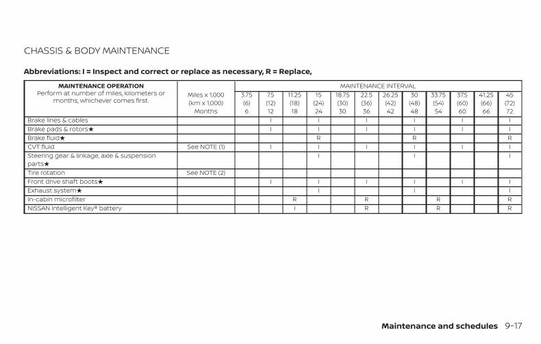
CHASSIS & BODY MAINTENANCE
Abbreviations: I = Inspect and correct or replace as necessary, R = Replace,
MAINTENANCE OPERATIONPerform at number of miles, kilometers or
months, whichever comes first.Miles x 1,000(km x 1,000)
Months
MAINTENANCE INTERVAL3.75(6)6
7.5(12)12
11.25(18)18
15(24)24
18.75(30)30
22.5(36)36
26.25(42)42
30(48)48
33.75(54)54
37.5(60)60
41.25(66)66
45(72)72
Brake lines & cables I I I I I IBrake pads & rotors� I I I I I IBrake fluid� R R RCVT fluid See NOTE (1) I I I I I ISteering gear & linkage, axle & suspensionparts�
I I I
Tire rotation See NOTE (2)Front drive shaft boots� I I I I I IExhaust system� I I IIn-cabin microfilter R R R RNISSAN Intelligent Key® battery I R R R
Maintenance and schedules 9-17
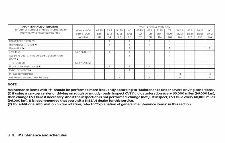
MAINTENANCE OPERATIONPerform at number of miles, kilometers or
months, whichever comes first.Miles x 1,000(km x 1,000)
Months
MAINTENANCE INTERVAL48.75(78)78
52.5(84)84
56.25(90)90
60(96)96
63.75(102)102
67.5(108)108
71.25(114)114
75(120)120
78.75(126)126
82.5(132)132
86.25(138)138
90(144)144
Brake lines & cables I I I I I IBrake pads & rotors� I I I I I IBrake fluid� R R RCVT fluid See NOTE (1) I I I I I ISteering gear & linkage, axle & suspensionparts�
I I I
Tire rotation See NOTE (2)Front drive shaft boots� I I I I I IExhaust system� I I IIn-cabin microfilter R R R RNISSAN Intelligent Key® battery R R R R
NOTE:
Maintenance items with “�” should be performed more frequently according to “Maintenance under severe driving conditions”.(1) If using a car-top carrier or driving on rough or muddy roads, inspect CVT fluid deterioration every 60,000 miles (96,000 km),then change CVT fluid if necessary. And if the inspection is not performed, change (not just inspect) CVT fluid every 60,000 miles(96,000 km). It is recommended that you visit a NISSAN dealer for this service.(2) For additional information on tire rotation, refer to “Explanation of general maintenance items” in this section.
9-18 Maintenance and schedules
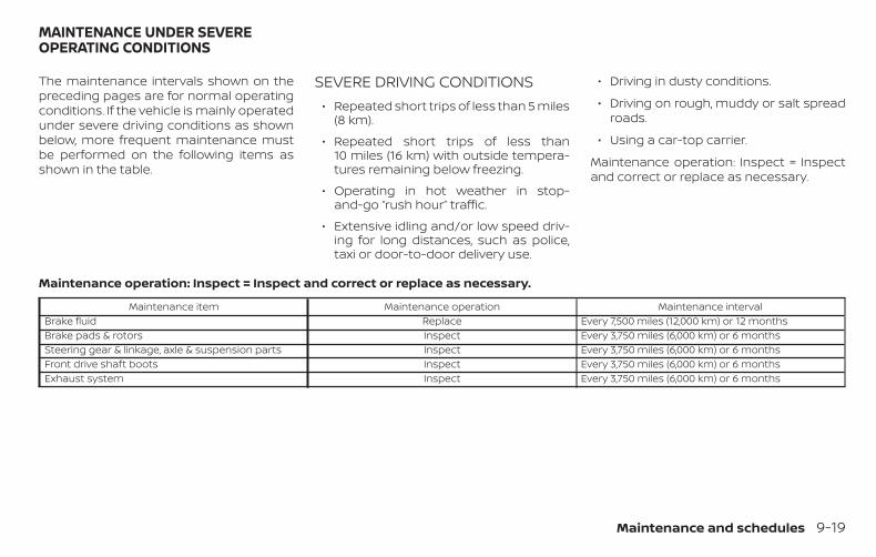
The maintenance intervals shown on thepreceding pages are for normal operatingconditions. If the vehicle is mainly operatedunder severe driving conditions as shownbelow, more frequent maintenance mustbe performed on the following items asshown in the table.
SEVERE DRIVING CONDITIONS∙ Repeated short trips of less than 5 miles
(8 km).
∙ Repeated short trips of less than10 miles (16 km) with outside tempera-tures remaining below freezing.
∙ Operating in hot weather in stop-and-go “rush hour” traffic.
∙ Extensive idling and/or low speed driv-ing for long distances, such as police,taxi or door-to-door delivery use.
∙ Driving in dusty conditions.
∙ Driving on rough, muddy or salt spreadroads.
∙ Using a car-top carrier.
Maintenance operation: Inspect = Inspectand correct or replace as necessary.
Maintenance operation: Inspect = Inspect and correct or replace as necessary.
Maintenance item Maintenance operation Maintenance intervalBrake fluid Replace Every 7,500 miles (12,000 km) or 12 monthsBrake pads & rotors Inspect Every 3,750 miles (6,000 km) or 6 monthsSteering gear & linkage, axle & suspension parts Inspect Every 3,750 miles (6,000 km) or 6 monthsFront drive shaft boots Inspect Every 3,750 miles (6,000 km) or 6 monthsExhaust system Inspect Every 3,750 miles (6,000 km) or 6 months
MAINTENANCE UNDER SEVEREOPERATING CONDITIONS
Maintenance and schedules 9-19
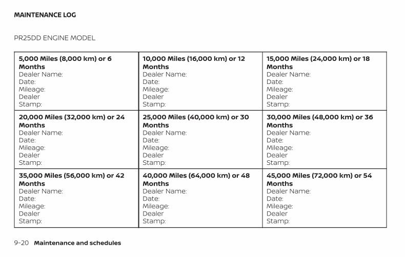
PR25DD ENGINE MODEL
5,000 Miles (8,000 km) or 6MonthsDealer Name:Date:Mileage:DealerStamp:
10,000 Miles (16,000 km) or 12MonthsDealer Name:Date:Mileage:DealerStamp:
15,000 Miles (24,000 km) or 18MonthsDealer Name:Date:Mileage:DealerStamp:
20,000 Miles (32,000 km) or 24MonthsDealer Name:Date:Mileage:DealerStamp:
25,000 Miles (40,000 km) or 30MonthsDealer Name:Date:Mileage:DealerStamp:
30,000 Miles (48,000 km) or 36MonthsDealer Name:Date:Mileage:DealerStamp:
35,000 Miles (56,000 km) or 42MonthsDealer Name:Date:Mileage:DealerStamp:
40,000 Miles (64,000 km) or 48MonthsDealer Name:Date:Mileage:DealerStamp:
45,000 Miles (72,000 km) or 54MonthsDealer Name:Date:Mileage:DealerStamp:
MAINTENANCE LOG
9-20 Maintenance and schedules
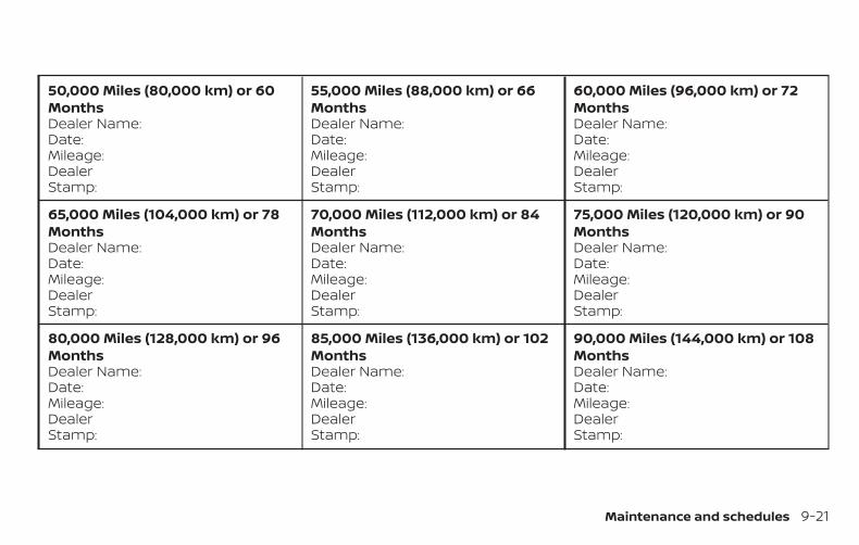
50,000 Miles (80,000 km) or 60MonthsDealer Name:Date:Mileage:DealerStamp:
55,000 Miles (88,000 km) or 66MonthsDealer Name:Date:Mileage:DealerStamp:
60,000 Miles (96,000 km) or 72MonthsDealer Name:Date:Mileage:DealerStamp:
65,000 Miles (104,000 km) or 78MonthsDealer Name:Date:Mileage:DealerStamp:
70,000 Miles (112,000 km) or 84MonthsDealer Name:Date:Mileage:DealerStamp:
75,000 Miles (120,000 km) or 90MonthsDealer Name:Date:Mileage:DealerStamp:
80,000 Miles (128,000 km) or 96MonthsDealer Name:Date:Mileage:DealerStamp:
85,000 Miles (136,000 km) or 102MonthsDealer Name:Date:Mileage:DealerStamp:
90,000 Miles (144,000 km) or 108MonthsDealer Name:Date:Mileage:DealerStamp:
Maintenance and schedules 9-21
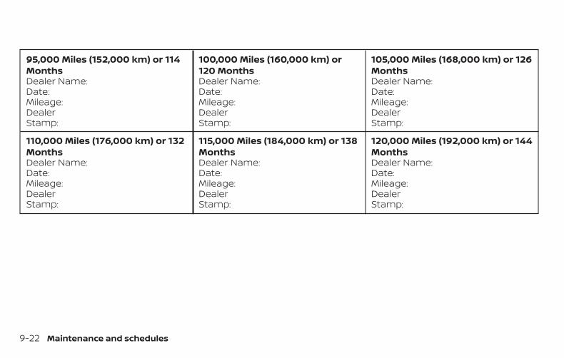
95,000 Miles (152,000 km) or 114MonthsDealer Name:Date:Mileage:DealerStamp:
100,000 Miles (160,000 km) or120 MonthsDealer Name:Date:Mileage:DealerStamp:
105,000 Miles (168,000 km) or 126MonthsDealer Name:Date:Mileage:DealerStamp:
110,000 Miles (176,000 km) or 132MonthsDealer Name:Date:Mileage:DealerStamp:
115,000 Miles (184,000 km) or 138MonthsDealer Name:Date:Mileage:DealerStamp:
120,000 Miles (192,000 km) or 144MonthsDealer Name:Date:Mileage:DealerStamp:
9-22 Maintenance and schedules
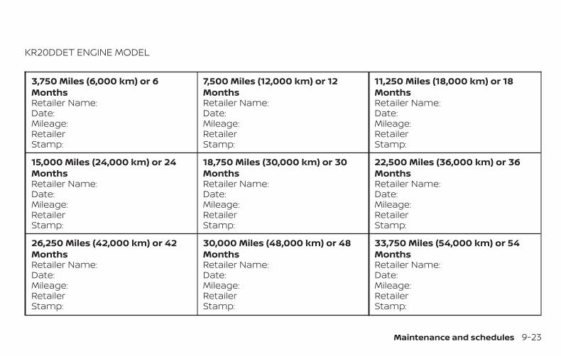
KR20DDET ENGINE MODEL
3,750 Miles (6,000 km) or 6MonthsRetailer Name:Date:Mileage:RetailerStamp:
7,500 Miles (12,000 km) or 12MonthsRetailer Name:Date:Mileage:RetailerStamp:
11,250 Miles (18,000 km) or 18MonthsRetailer Name:Date:Mileage:RetailerStamp:
15,000 Miles (24,000 km) or 24MonthsRetailer Name:Date:Mileage:RetailerStamp:
18,750 Miles (30,000 km) or 30MonthsRetailer Name:Date:Mileage:RetailerStamp:
22,500 Miles (36,000 km) or 36MonthsRetailer Name:Date:Mileage:RetailerStamp:
26,250 Miles (42,000 km) or 42MonthsRetailer Name:Date:Mileage:RetailerStamp:
30,000 Miles (48,000 km) or 48MonthsRetailer Name:Date:Mileage:RetailerStamp:
33,750 Miles (54,000 km) or 54MonthsRetailer Name:Date:Mileage:RetailerStamp:
Maintenance and schedules 9-23
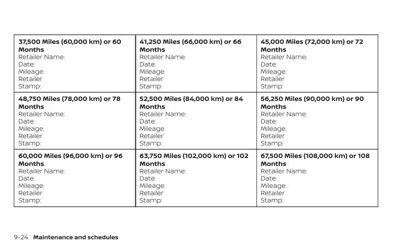
37,500 Miles (60,000 km) or 60MonthsRetailer Name:Date:Mileage:RetailerStamp:
41,250 Miles (66,000 km) or 66MonthsRetailer Name:Date:Mileage:RetailerStamp:
45,000 Miles (72,000 km) or 72MonthsRetailer Name:Date:Mileage:RetailerStamp:
48,750 Miles (78,000 km) or 78MonthsRetailer Name:Date:Mileage:RetailerStamp:
52,500 Miles (84,000 km) or 84MonthsRetailer Name:Date:Mileage:RetailerStamp:
56,250 Miles (90,000 km) or 90MonthsRetailer Name:Date:Mileage:RetailerStamp:
60,000 Miles (96,000 km) or 96MonthsRetailer Name:Date:Mileage:RetailerStamp:
63,750 Miles (102,000 km) or 102MonthsRetailer Name:Date:Mileage:RetailerStamp:
67,500 Miles (108,000 km) or 108MonthsRetailer Name:Date:Mileage:RetailerStamp:
9-24 Maintenance and schedules
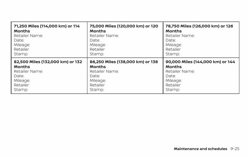
71,250 Miles (114,000 km) or 114MonthsRetailer Name:Date:Mileage:RetailerStamp:
75,000 Miles (120,000 km) or 120MonthsRetailer Name:Date:Mileage:RetailerStamp:
78,750 Miles (126,000 km) or 126MonthsRetailer Name:Date:Mileage:RetailerStamp:
82,500 Miles (132,000 km) or 132MonthsRetailer Name:Date:Mileage:RetailerStamp:
86,250 Miles (138,000 km) or 138MonthsRetailer Name:Date:Mileage:RetailerStamp:
90,000 Miles (144,000 km) or 144MonthsRetailer Name:Date:Mileage:RetailerStamp:
Maintenance and schedules 9-25

MEMO
9-26 Maintenance and schedules
10 Technical and consumer information
Recommended fluids/lubricants andcapacities . . . . . . . . . . . . . . . . . . . . . . . . . . . . . . . . . . . . . . 10-2
Fuel recommendation. . . . . . . . . . . . . . . . . . . . . . . 10-4Engine oil and oil filterrecommendations . . . . . . . . . . . . . . . . . . . . . . . . . . 10-6Air conditioner system refrigerant andoil recommendations . . . . . . . . . . . . . . . . . . . . . . . 10-7
Specifications . . . . . . . . . . . . . . . . . . . . . . . . . . . . . . . . . . 10-8Engine . . . . . . . . . . . . . . . . . . . . . . . . . . . . . . . . . . . . . . 10-8Wheels and tires. . . . . . . . . . . . . . . . . . . . . . . . . . . . . 10-9Dimensions and weights . . . . . . . . . . . . . . . . . . . . 10-9
When traveling or registering in anothercountry. . . . . . . . . . . . . . . . . . . . . . . . . . . . . . . . . . . . . . . . 10-10Vehicle identification . . . . . . . . . . . . . . . . . . . . . . . . . . 10-10
Vehicle Identification Number (VIN)plate . . . . . . . . . . . . . . . . . . . . . . . . . . . . . . . . . . . . . . . 10-10Vehicle identification number(chassis number) . . . . . . . . . . . . . . . . . . . . . . . . . . . 10-10Engine serial number. . . . . . . . . . . . . . . . . . . . . . . . 10-11F.M.V.S.S./C.M.V.S.S. certification label . . . . . . . . . 10-11Emission control information label . . . . . . . . . 10-12
Tire and Loading Information label . . . . . . . . . 10-12Air conditioner specification label. . . . . . . . . . . 10-12
Installing front license plate. . . . . . . . . . . . . . . . . . . . 10-13Vehicle loading information . . . . . . . . . . . . . . . . . . . 10-13
Terms . . . . . . . . . . . . . . . . . . . . . . . . . . . . . . . . . . . . . . 10-13Vehicle load capacity . . . . . . . . . . . . . . . . . . . . . . . 10-14Loading tips . . . . . . . . . . . . . . . . . . . . . . . . . . . . . . . . 10-16Measurement of weights . . . . . . . . . . . . . . . . . . . 10-16
Towing a trailer . . . . . . . . . . . . . . . . . . . . . . . . . . . . . . . . 10-17Flat towing . . . . . . . . . . . . . . . . . . . . . . . . . . . . . . . . . 10-17
Uniform tire quality grading. . . . . . . . . . . . . . . . . . . . 10-17Emission control system warranty. . . . . . . . . . . . . 10-18Reporting safety defects . . . . . . . . . . . . . . . . . . . . . . 10-19Readiness for Inspection/Maintenance (I/M)test. . . . . . . . . . . . . . . . . . . . . . . . . . . . . . . . . . . . . . . . . . . . 10-20Event Data Recorders (EDR). . . . . . . . . . . . . . . . . . . . 10-20
Additional Data Recording (on vehiclesequipped with optional ProPILOTAssist) . . . . . . . . . . . . . . . . . . . . . . . . . . . . . . . . . . . . . . 10-21
Owner’s Manual/Service Manual orderinformation . . . . . . . . . . . . . . . . . . . . . . . . . . . . . . . . . . . 10-22
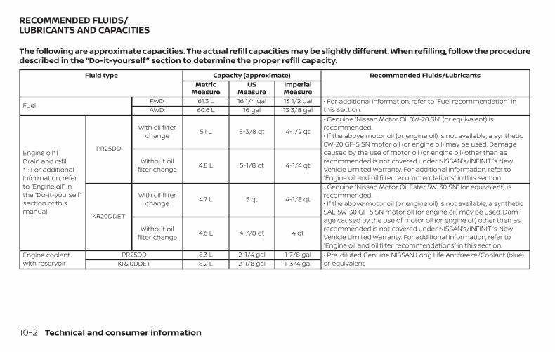
The following are approximate capacities. The actual refill capacities may be slightly different. When refilling, follow the proceduredescribed in the “Do-it-yourself” section to determine the proper refill capacity.
Fluid type Capacity (approximate) Recommended Fluids/LubricantsMetric
MeasureUS
MeasureImperialMeasure
FuelFWD: 61.3 L 16 1/4 gal 13 1/2 gal • For additional information, refer to “Fuel recommendation” in
this section.AWD: 60.6 L 16 gal 13 3/8 gal
Engine oil*1Drain and refill*1: For additionalinformation, referto “Engine oil” inthe “Do-it-yourself ”section of thismanual.
PR25DD
With oil filterchange 5.1 L 5-3/8 qt 4-1/2 qt
• Genuine “Nissan Motor Oil 0W-20 SN” (or equivalent) isrecommended.• If the above motor oil (or engine oil) is not available, a synthetic0W-20 GF-5 SN motor oil (or engine oil) may be used. Damagecaused by the use of motor oil (or engine oil) other than asrecommended is not covered under NISSAN’s/INFINITI’s NewVehicle Limited Warranty. For additional information, refer to“Engine oil and oil filter recommendations” in this section.
Without oilfilter change 4.8 L 5-1/8 qt 4-1/4 qt
KR20DDET
With oil filterchange 4.7 L 5 qt 4-1/8 qt
• Genuine “Nissan Motor Oil Ester 5W-30 SN” (or equivalent) isrecommended.• If the above motor oil (or engine oil) is not available, a syntheticSAE 5W-30 GF-5 SN motor oil (or engine oil) may be used. Dam-age caused by the use of motor oil (or engine oil) other then asrecommended is not covered under NISSAN’s/INFINITI’s NewVehicle Limited Warranty. For additional information, refer to“Engine oil and oil filter recommendations” in this section.
Without oilfilter change 4.6 L 4-7/8 qt 4 qt
Engine coolantwith reservoir
PR25DD 8.3 L 2-1/4 gal 1-7/8 gal • Pre-diluted Genuine NISSAN Long Life Antifreeze/Coolant (blue)or equivalentKR20DDET 8.2 L 2-1/8 gal 1-3/4 gal
RECOMMENDED FLUIDS/LUBRICANTS AND CAPACITIES
10-2 Technical and consumer information
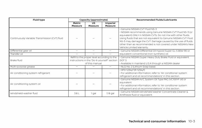
Fluid type Capacity (approximate) Recommended Fluids/LubricantsMetric
MeasureUS
MeasureImperialMeasure
Continuously Variable Transmission (CVT) fluid — — —
• Genuine NISSAN CVT Fluid NS-3• NISSAN recommends using Genuine NISSAN CVT Fluid NS-3 (orequivalent) ONLY in NISSAN CVTs. Do not mix with other fluids.Using fluids that are not equivalent to Genuine NISSAN CVT FluidNS-3 may damage the CVT. Damage caused by the use of fluidsother than as recommended is not covered under NISSAN’s NewVehicle Limited Warranty.
Differential gear oil — — — • Genuine NISSAN Differential Oil Hypoid Super GL-5 80W-90 orequivalent conventional (non-synthetic) oil.Transfer oil — — —
Brake fluidRefill to the proper level according to the
instructions in the “Do-it-yourself ” sectionof this manual.
• Genuine NISSAN Super Heavy Duty Brake Fluid or equivalentDOT 3.• Available in mainland U.S.A through a NISSAN dealer
Multi-purpose grease — — — • NLGI No. 2 (Lithium Soap base)
Air conditioning system refrigerant — — —• HF0-1234yf (R-1234yf)• For additional information, refer to “Air conditioner systemrefrigerant and oil recommendations” in this section.
Air conditioning system oil — — —
• Genuine NISSAN A/C System Oil Type PAG (VC100YF oil) orequivalent• For additional information, refer to “Air conditioner systemrefrigerant and oil recommendations” in this section.
Windshield-washer fluid 3.8 L 1 gal 7/8 gal • Genuine NISSAN Windshield Washer Concentrate Cleaner &Antifreeze fluid or equivalent.
Technical and consumer information 10-3
FUEL RECOMMENDATIONUse unleaded regular gasoline with an oc-tane rating of at least 87 AKI (Anti-Knock In-dex) number (Research octane number 91).
CAUTION∙ Only vehicles with the E-85 filler door
label can operate on E-85. Fuel systemor other damage can occur if E-85 isused in vehicles that are not designedto run on E-85.
∙ Using a fuel other than that specifiedcould adversely affect the emissioncontrol system, and may also affectthe warranty coverage.
∙ Under no circumstances should aleaded gasoline be used, because thiswill damage the three-way catalyst.
∙ Do not use a fuel containing morethan 15% ethanol in your vehicle. Yourvehicle is not designed to run on a fuelcontaining more than 15% ethanol.Using a fuel containing more than 15%ethanol in a vehicle not specificallydesigned for a fuel containing morethan 15% ethanol can adversely affectthe emission control devices and sys-tems of the vehicle. Damage causedby such fuel is not covered by theNISSAN New Vehicle Limited Warranty.
∙ Do not use fuel that contains the oc-tane booster methylcyclopentadienylmanganese tricarbonyl (MMT). Usingfuel containing MMT may adversely af-fect vehicle performance and vehicleemissions. Not all fuel dispensers arelabeled to indicate MMT content, so youmay have to consult your gasoline re-tailer for more details. Note that Fed-eral and California laws prohibit the useof MMT in reformulated gasoline.
∙ U.S. government regulations requireethanol dispensing pumps to be iden-tified by a small, square, orange andblack label with the common abbre-viation or the appropriate percentagefor that region.
Gasoline specificationsNISSAN recommends using gasoline thatmeets the World-Wide Fuel Charter (WWFC)specifications where it is available. Many ofthe automobile manufacturers developedthis specification to improve emission con-trol system and vehicle performance. Askyour service station manager if the gaso-line meets the WWFC specifications.
Reformulated gasolineSome fuel suppliers are now producing re-formulated gasolines. These gasolines arespecially designed to reduce vehicle emis-sions. NISSAN supports efforts towardscleaner air and suggests that you use re-formulated gasoline when available.
Gasoline containing oxygenatesSome fuel suppliers sell gasoline contain-ing oxygenates such as ethanol, MethylTert-butyl Ether (MTBE) and methanol withor without advertising their presence.NISSAN does not recommend the use offuels of which the oxygenate content andthe fuel compatibility for your NISSAN can-not be readily determined. If in doubt, askyour service station manager.
10-4 Technical and consumer information
If you use oxygenate-blend gasoline,please take the following precautions asthe usage of such fuels may cause vehicleperformance problems and/or fuel systemdamage.
∙ The fuel should be unleaded and havean octane rating no lower than thatrecommended for unleaded gasoline.
∙ If an oxygenate-blend other thanmethanol blend is used, it shouldcontain no more than 15% oxygenate.
∙ If a methanol blend is used, it shouldcontain no more than 5% methanol(methyl alcohol, wood alcohol). Itshould also contain a suitableamount of appropriate cosolventsand corrosion inhibitors. If not prop-erly formulated with appropriate co-solvents and corrosion inhibitors,such methanol blends may cause fuelsystem damage and/or vehicle per-formance problems. At this time, suf-ficient data is not available to ensurethat all methanol blends are suitablefor use in NISSAN vehicles.
If any driveability problems such as enginestalling and difficult hot-starting are expe-rienced after using oxygenate-blend fuels,
immediately change to a non-oxygenatefuel or a fuel with a low blend of MTBE.
Take care not to spill gasoline during re-fueling. Gasoline containing oxygenatescan cause paint damage.
E–15 fuelE-15 fuel is a mixture of approximately 15%fuel ethanol and 85% unleaded gasoline.E-15 can only be used in vehicles designedto run on E-15 fuel. U.S. government regula-tions require fuel ethanol dispensingpumps to be identified with small, square,orange and black label with the commonabbreviation or the appropriate percent-age for that region.
E–85 fuelE-85 fuel is a mixture of approximately 85%fuel ethanol and 15% unleaded gasoline.E-85 can only be used in a Flexible FuelVehicle (FFV). Do not use E-85 in your ve-hicle. U.S. government regulations requirefuel ethanol dispensing pumps to be iden-tified by a small, square, orange and blacklabel with the common abbreviation or theappropriate percentage for that region.
Fuel containing MMTMMT, or methylcyclopentadienyl manga-nese tricarbonyl, is an octane boosting ad-ditive. NISSAN does not recommend theuse of fuel containing MMT. Such fuel mayadversely affect vehicle performance, in-cluding the emissions control system. Notethat while some fuel pumps label MMTcontent, not all do, so you may have toconsult your gasoline retailer for more de-tails.
Aftermarket fuel additivesNISSAN does not recommend the use ofany aftermarket fuel additives (for ex-ample, fuel injector cleaner, octanebooster, intake valve deposit removers,etc.) which are sold commercially. Many ofthese additives intended for gum, varnishor deposit removal may contain active sol-vents or similar ingredients that can beharmful to the fuel system and engine.
Technical and consumer information 10-5
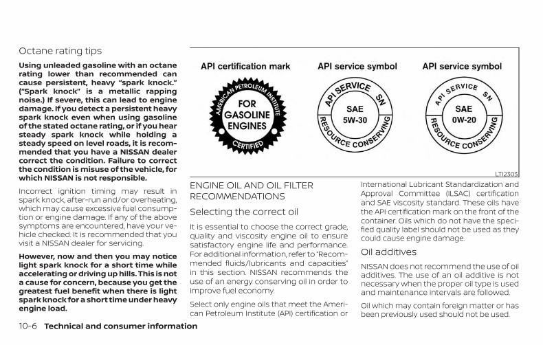
Octane rating tipsUsing unleaded gasoline with an octanerating lower than recommended cancause persistent, heavy “spark knock.”(“Spark knock” is a metallic rappingnoise.) If severe, this can lead to enginedamage. If you detect a persistent heavyspark knock even when using gasolineof the stated octane rating, or if you hearsteady spark knock while holding asteady speed on level roads, it is recom-mended that you have a NISSAN dealercorrect the condition. Failure to correctthe condition is misuse of the vehicle, forwhich NISSAN is not responsible.
Incorrect ignition timing may result inspark knock, after-run and/or overheating,which may cause excessive fuel consump-tion or engine damage. If any of the abovesymptoms are encountered, have your ve-hicle checked. It is recommended that youvisit a NISSAN dealer for servicing.
However, now and then you may noticelight spark knock for a short time whileaccelerating or driving up hills. This is nota cause for concern, because you get thegreatest fuel benefit when there is lightspark knock for a short time under heavyengine load.
ENGINE OIL AND OIL FILTERRECOMMENDATIONSSelecting the correct oilIt is essential to choose the correct grade,quality and viscosity engine oil to ensuresatisfactory engine life and performance.For additional information, refer to “Recom-mended fluids/lubricants and capacities”in this section. NISSAN recommends theuse of an energy conserving oil in order toimprove fuel economy.
Select only engine oils that meet the Ameri-can Petroleum Institute (API) certification or
International Lubricant Standardization andApproval Committee (ILSAC) certificationand SAE viscosity standard. These oils havethe API certification mark on the front of thecontainer. Oils which do not have the speci-fied quality label should not be used as theycould cause engine damage.
Oil additivesNISSAN does not recommend the use of oiladditives. The use of an oil additive is notnecessary when the proper oil type is usedand maintenance intervals are followed.
Oil which may contain foreign matter or hasbeen previously used should not be used.
LTI2303
10-6 Technical and consumer information
Oil viscosityThe engine oil viscosity or thicknesschanges with temperature. Because ofthis, it is important to select the engine oilviscosity based on the temperatures atwhich the vehicle will be operated beforethe next oil change. Choosing an oil viscos-ity other than that recommended couldcause serious engine damage.
Selecting the correct oil filterYour new NISSAN vehicle is equipped with ahigh-quality Genuine NISSAN oil filter. Whenreplacing, use a Genuine NISSAN oil filter orits equivalent for the reason described in“Change intervals.”
Change intervalsThe oil and oil filter change intervals foryour engine are based on the use of thespecified quality oils and filters. Using en-gine oil and filters that are not of the speci-fied quality, or exceeding recommended oiland filter change intervals could reduceengine life. Damage to the engine causedby improper maintenance or use of incor-rect oil and filter quality and/or viscosity isnot covered by the NISSAN New VehicleLimited Warranty.
Your engine was filled with a high-qualityengine oil when it was built. You do not haveto change the oil before the first recom-mended change interval. Oil and filterchange intervals depend upon how youuse your vehicle.
Operation under the following conditionsmay require more frequent oil and filterchanges:
∙ repeated short distance driving at coldoutside temperatures
∙ driving in dusty conditions
∙ extensive idling
∙ stop and go commuting
For additional information, refer to the“Maintenance and schedules” section ofthis manual.
AIR CONDITIONER SYSTEMREFRIGERANT AND OILRECOMMENDATIONSThe air conditioner system in yourNISSAN vehicle must be charged withthe refrigerant HFO-1234yf (R-1234yf)and NISSAN A/C system oil Type PAG(VC100YF oil) or the exact equivalents.
CAUTIONThe use of any other refrigerant or oilwill cause severe damage to the air con-ditioning system and will require the re-placement of all air conditioner systemcomponents.
The refrigerant HFO-1234yf (R-1234yf) in yourNISSAN vehicle does not harm the earth’sozone layer. Although this refrigerant doesnot affect the earth’s atmosphere, certaingovernment regulations require the recoveryand recycling of any refrigerant during auto-motive air conditioner system service. Airconditioner system should only be servicedby trained and certified technicians to ensureproper and safe operation (SAE J2845). ANISSAN dealer has the trained techniciansand equipment needed to recover and re-cycle your air conditioner system refrigerant.Only new and SAEJ2842 certified evapora-tor(s) shall be used as replacement parts.
A damaged or leaking air conditioningevaporator shall never be repaired or re-placed with one removed from a used orsalvaged vehicle. To replace a damaged orleaking evaporator, use only new and SAEJ2842 certified evaporator(s). It is recom-mended that you visit a NISSAN dealer whenservicing your air conditioner system.
Technical and consumer information 10-7
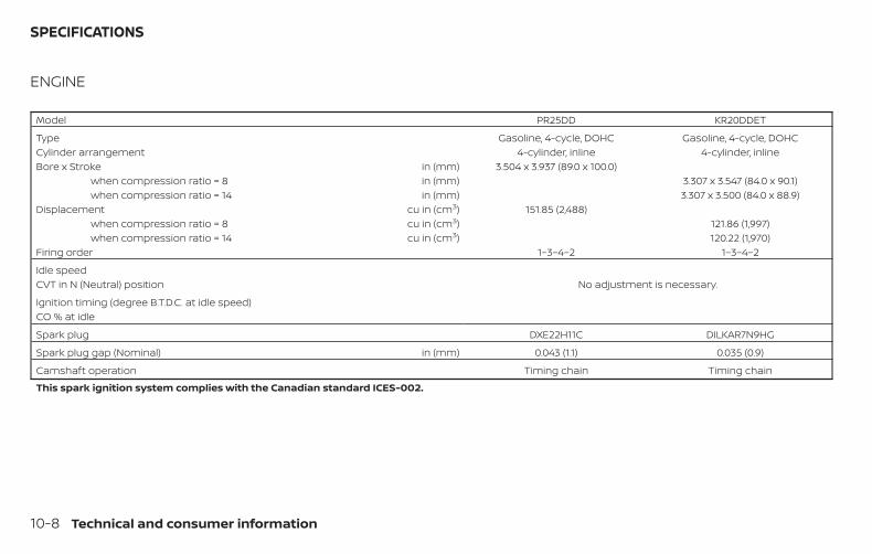
ENGINE
Model PR25DD KR20DDET
Type Gasoline, 4-cycle, DOHC Gasoline, 4-cycle, DOHCCylinder arrangement 4-cylinder, inline 4-cylinder, inlineBore x Stroke in (mm) 3.504 x 3.937 (89.0 x 100.0)
when compression ratio = 8 in (mm) 3.307 x 3.547 (84.0 x 90.1)when compression ratio = 14 in (mm) 3.307 x 3.500 (84.0 x 88.9)
Displacement cu in (cm3) 151.85 (2,488)when compression ratio = 8 cu in (cm3) 121.86 (1,997)when compression ratio = 14 cu in (cm3) 120.22 (1,970)
Firing order 1–3–4–2 1–3–4–2
Idle speedCVT in N (Neutral) position No adjustment is necessary.
Ignition timing (degree B.T.D.C. at idle speed)CO % at idle
Spark plug DXE22H11C DILKAR7N9HG
Spark plug gap (Nominal) in (mm) 0.043 (1.1) 0.035 (0.9)
Camshaft operation Timing chain Timing chain
This spark ignition system complies with the Canadian standard ICES-002.
SPECIFICATIONS
10-8 Technical and consumer information
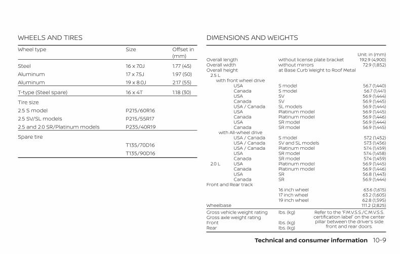
WHEELS AND TIRESWheel type Size Offset in
(mm)
Steel 16 x 7.0J 1.77 (45)Aluminum 17 x 7.5J 1.97 (50)Aluminum 19 x 8.0J 2.17 (55)
T-type (Steel spare) 16 x 4T 1.18 (30)
Tire size2.5 S model P215/60R162.5 SV/SL models P215/55R172.5 and 2.0 SR/Platinum models P235/40R19
Spare tireT135/70D16T135/90D16
DIMENSIONS AND WEIGHTS
Unit: in (mm)Overall length without license plate bracket 192.9 (4,900)Overall width without mirrors 72.9 (1,852)Overall height at Base Curb Weight to Roof Metal
2.5 Lwith front wheel drive
USA S model 56.7 (1,440)Canada S model 56.7 (1,441)USA SV 56.9 (1,444)Canada SV 56.9 (1,445)USA / Canada SL models 56.9 (1,444)USA Platinum model 56.9 (1,445)Canada Platinum model 56.9 (1,446)USA SR model 56.9 (1,444)Canada SR model 56.9 (1,445)
with All-wheel driveUSA / Canada S model 57.2 (1,452)USA / Canada SV and SL models 57.3 (1,456)USA / Canada Platinum model 57.4 (1,459)USA SR model 57.4 (1,458)Canada SR model 57.4 (1,459)
2.0 L USA Platinum model 56.9 (1,445)Canada Platinum model 56.9 (1,446)USA SR 56.8 (1,443)Canada SR 56.9 (1,444)
Front and Rear track16 inch wheel 63.6 (1,615)17 inch wheel 63.2 (1,605)19 inch wheel 62.8 (1,595)
Wheelbase 111.2 (2,825)Gross vehicle weight rating lbs. (kg) Refer to the “F.M.V.S.S./C.M.V.S.S.
certification label” on the centerpillar between the driver’s side
front and rear doors.
Gross axle weight ratingFront lbs. (kg)Rear lbs. (kg)
Technical and consumer information 10-9
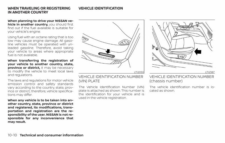
When planning to drive your NISSAN ve-hicle in another country, you should firstfind out if the fuel available is suitable foryour vehicle's engine.
Using fuel with an octane rating that is toolow may cause engine damage. All gaso-line vehicles must be operated with un-leaded gasoline. Therefore, avoid takingyour vehicle to areas where appropriatefuel is not available.
When transferring the registration ofyour vehicle to another country, state,province or district, it may be necessaryto modify the vehicle to meet local lawsand regulations.
The laws and regulations for motor vehicleemission control and safety standardsvary according to the country, state, prov-ince or district; therefore, vehicle specifica-tions may differ.
When any vehicle is to be taken into an-other country, state, province or districtand registered, its modifications, trans-portation and registration are the re-sponsibility of the user. NISSAN is not re-sponsible for any inconvenience thatmay result.
VEHICLE IDENTIFICATION NUMBER(VIN) PLATEThe Vehicle Identification Number (VIN)plate is attached as shown. This number isthe identification for your vehicle and isused in the vehicle registration.
VEHICLE IDENTIFICATION NUMBER(chassis number)The vehicle identification number is lo-cated as shown.
LTI2050 LTI2387
WHEN TRAVELING OR REGISTERINGIN ANOTHER COUNTRY
VEHICLE IDENTIFICATION
10-10 Technical and consumer information
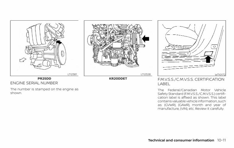
ENGINE SERIAL NUMBERThe number is stamped on the engine asshown.
F.M.V.S.S./C.M.V.S.S. CERTIFICATIONLABELThe Federal/Canadian Motor VehicleSafety Standard (F.M.V.S.S./C.M.V.S.S.) certifi-cation label is affixed as shown. This labelcontains valuable vehicle information, suchas: (GVWR), (GAWR), month and year ofmanufacture, (VIN), etc. Review it carefully.
PR25DDLTI2381
KR20DDETLTI2328 WTI0172
Technical and consumer information 10-11
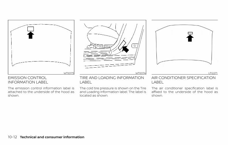
EMISSION CONTROLINFORMATION LABELThe emission control information label isattached to the underside of the hood asshown.
TIRE AND LOADING INFORMATIONLABELThe cold tire pressure is shown on the Tireand Loading Information label. The label islocated as shown.
AIR CONDITIONER SPECIFICATIONLABELThe air conditioner specification label isaffixed to the underside of the hood asshown.
WTI0173 WTI0174 LTI2271
10-12 Technical and consumer information
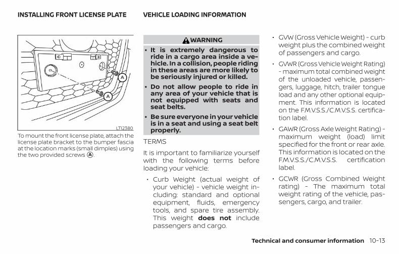
To mount the front license plate, attach thelicense plate bracket to the bumper fasciaat the location marks (small dimples) usingthe two provided screws �A .
WARNING∙ It is extremely dangerous to
ride in a cargo area inside a ve-hicle. In a collision, people ridingin these areas are more likely tobe seriously injured or killed.
∙ Do not allow people to ride inany area of your vehicle that isnot equipped with seats andseat belts.
∙ Be sure everyone in your vehicleis in a seat and using a seat beltproperly.
TERMSIt is important to familiarize yourselfwith the following terms beforeloading your vehicle:
∙ Curb Weight (actual weight ofyour vehicle) - vehicle weight in-cluding: standard and optionalequipment, fluids, emergencytools, and spare tire assembly.This weight does not includepassengers and cargo.
∙ GVW (Gross Vehicle Weight) - curbweight plus the combined weightof passengers and cargo.
∙ GVWR (Gross Vehicle Weight Rating)- maximum total combined weightof the unloaded vehicle, passen-gers, luggage, hitch, trailer tongueload and any other optional equip-ment. This information is locatedon the F.M.V.S.S./C.M.V.S.S. certifica-tion label.
∙ GAWR (Gross Axle Weight Rating) -maximum weight (load) limitspecified for the front or rear axle.This information is located on theF.M.V.S.S./C.M.V.S.S. certificationlabel.
∙ GCWR (Gross Combined Weightrating) - The maximum totalweight rating of the vehicle, pas-sengers, cargo, and trailer.
LTI2380
INSTALLING FRONT LICENSE PLATE VEHICLE LOADING INFORMATION
Technical and consumer information 10-13
∙ Vehicle Capacity Weight, Loadlimit, Total load capacity - maxi-mum total weight limit specifiedof the load (passengers andcargo) for the vehicle. This is themaximum combined weight ofoccupants and cargo that can beloaded into the vehicle. If the ve-hicle is used to tow a trailer, thetrailer tongue weight must beincluded as part of the cargoload. This information is locatedon the Tire and Loading Informa-tion label.
∙ Cargo capacity - permissibleweight of cargo, the subtractedweight of occupants from theload limit.
VEHICLE LOAD CAPACITYDo not exceed the load limit of yourvehicle shown as “The combinedweight of occupants and cargo” onthe Tire and Loading Informationlabel. Do not exceed the numberof occupants shown as “SeatingCapacity” on the Tire and LoadingInformation label.To get “the combined weight ofoccupants and cargo”, add theweight of all occupants, then add thetotal luggage weight. Examples areshown in the following illustration.
10-14 Technical and consumer information
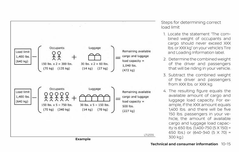
Steps for determining correctload limit
1. Locate the statement “The com-bined weight of occupants andcargo should never exceed XXXlbs. or XXX kg” on your vehicle’s Tireand Loading Information label.
2. Determine the combined weightof the driver and passengersthat will be riding in your vehicle.
3. Subtract the combined weightof the driver and passengersfrom XXX lbs. or XXX kg.
4. The resulting figure equals theavailable amount of cargo andluggage load capacity. For ex-ample, if the XXX amount equals1,400 lbs. and there will be five150 lbs. passengers in your ve-hicle, the amount of availablecargo and luggage load capac-ity is 650 lbs. (1,400-750 (5 X 150) =650 lbs.) or (640-340 (5 X 70) =300 kg.)Example
LTI2335
Technical and consumer information 10-15
5. Determine the combined weightof luggage and cargo beingloaded on the vehicle. Thatweight may not safely exceedthe available cargo and luggageload capacity calculated instep 4.
Before driving a loaded vehicle, con-firm that you do not exceed theGross Vehicle Weight Rating (GVWR)or the Gross Axle Weight Rating(GAWR) for your vehicle. For addi-tional information, refer to “Measure-ment of weights” in this section.Also check tires for proper inflationpressures. For additional informa-tion, refer to “Tire and Loading Infor-mation label” in this section.
LOADING TIPS∙ The GVW must not exceed GVWR or
GAWR as specified on the F.M.V.S.S./C.M.V.S.S. certification label.
∙ Do not load the front and rearaxle to the GAWR. Doing so willexceed the GVWR.
WARNING∙ Properly secure all cargo with
ropes or straps to help preventit from sliding or shifting. Do notplace cargo higher than theseatbacks. In a sudden stop orcollision, unsecured cargo couldcause personal injury.
∙ Do not load your vehicle anyheavier than the GVWR or themaximum front and rearGAWRs. If you do, parts of yourvehicle can break, tire damagecould occur, or it can change theway your vehicle handles. Thiscould result in loss of controland cause personal injury.
∙ Overloading not only canshorten the life of your vehicleand the tire, but can also causeunsafe vehicle handling andlonger braking distances. Thismay cause a premature tirefailure which could result in aserious accident and personalinjury. Failures caused by over-loading are not covered by thevehicle’s warranty.
MEASUREMENT OF WEIGHTSSecure loose items to preventweight shifts that could affect thebalance of your vehicle. When the ve-hicle is loaded, drive to a scale andweigh the front and the rear wheelsseparately to determine axle loads.Individual axle loads should not ex-ceed either of the gross axle weightratings (GAWR). The total of the axleloads should not exceed the grossvehicle weight rating (GVWR). Theseratings are given on the vehicle cer-tification label. If weight ratings areexceeded, move or remove items tobring all weights below the ratings.
10-16 Technical and consumer information
Do not tow a trailer with your vehicle.
FLAT TOWINGTowing your vehicle with all four wheels onthe ground is sometimes called flat towing.This method is sometimes used whentowing a vehicle behind a recreational ve-hicle, such as a motor home.
CAUTION∙ Failure to follow these guidelines can
result in severe transmission damage.
∙ Whenever flat towing your vehicle, al-ways tow forward, never backward.
∙ Never tow your front wheel drive ve-hicle with the front tires on theground. Doing so may cause seriousand expensive damage to thepowertrain.
∙ DO NOT tow any continuously variabletransmission vehicle with all fourwheels on the ground (flat towing).Doing so WILL DAMAGE internal trans-mission parts due to lack of transmis-sion lubrication.
∙ For emergency towing proceduresrefer to “Towing recommended byNISSAN” in the “In case of emergency”section of this manual.
Continuously VariableTransmission (CVT)To tow a vehicle equipped with a CVT, anappropriate vehicle dolly MUST be placedunder the towed vehicle’s drive wheels.Always follow the dolly manufacturer’s rec-ommendations when using their product.
DOT (Department of Transportation) Qual-ity Grades: All passenger car tires mustconform to federal safety requirements inaddition to these grades.
Quality grades can be found where appli-cable on the tire sidewall between treadshoulder and maximum section width. Forexample:
Treadwear 200 Traction AA Temperature A
Treadwear
The treadwear grade is a comparative rat-ing based on the wear rate of the tire whentested under controlled conditions on aspecified government test course. For ex-ample, a tire graded 150 would wear oneand one-half (1 1/2) times as well on thegovernment course as a tire graded 100.The relative performance of tires dependsupon the actual conditions of their use,however, and may depart significantly fromthe norm due to variations in driving habits,service practices and differences in roadcharacteristics and climate.
TOWING A TRAILER UNIFORM TIRE QUALITY GRADING
Technical and consumer information 10-17
Traction AA, A, B and C
The traction grades, from highest to low-est, are AA, A, B, and C. Those grades repre-sent the tire’s ability to stop on wet pave-ment as measured under controlledconditions on specified government testsurfaces of asphalt and concrete. A tiremarked C may have poor traction perfor-mance.
WARNINGThe traction grade assigned to this tireis based on straight-ahead brakingtraction tests, and does not include ac-celeration, cornering, hydroplaning, orpeak traction characteristics.
Temperature A, B and C
The temperature grades are A (the high-est), B, and C, representing the tire’s resis-tance to the generation of heat, and itsability to dissipate heat when tested undercontrolled conditions on a specified indoorlaboratory test wheel. Sustained high tem-perature can cause the material of the tireto degenerate and reduce tire life, and ex-cessive temperature can lead to suddentire failure. The grade C corresponds to a
level of performance which all passengercar tires must meet under the FederalMotor Vehicle Safety Standard No. 109.Grades B and A represent higher levels ofperformance on the laboratory test wheelthan the minimum required by law.
WARNINGThe temperature grade for this tire isestablished for a tire that is properly in-flated and not overloaded. Excessivespeed, under-inflation, or excessiveloading, either separately or in combi-nation, can cause heat build-up andpossible tire failure.
Your NISSAN vehicle is covered by the fol-lowing emission warranties:
For USA
1. Emission Defects Warranty
2. Emissions Performance Warranty
Details of this warranty may be found withother vehicle warranties in your Warranty In-formation Booklet which comes with yourNISSAN vehicle. If you did not receive a War-ranty Information Booklet, or it is lost, youmay obtain a replacement by writing to:
∙ Nissan North America, Inc.Consumer Affairs DepartmentP.O. Box 685003Franklin, TN 37068-5003
For Canada
Emission Control System Warranty
Details of this warranty may be found withother vehicle warranties in your Warranty In-formation Booklet which comes with yourNISSAN vehicle. If you did not receive a War-ranty Information Booklet, or it is lost, youmay obtain a replacement by writing to:
∙ Nissan Canada Inc.5290 Orbitor DriveMississauga, Ontario, L4W 4Z5
EMISSION CONTROL SYSTEMWARRANTY
10-18 Technical and consumer information
For USA
If you believe that your vehicle has adefect which could cause a crash orcould cause injury or death, youshould immediately inform the Na-tional Highway Traffic Safety Admin-istration (NHTSA) in addition to noti-fying NISSAN.
If NHTSA receives similar complaints,it may open an investigation, and if itfinds that a safety defect exists in agroup of vehicles, it may order a re-call and remedy campaign. However,NHTSA cannot become involved inindividual problems between you,your dealer, or NISSAN.
To contact NHTSA, you may call theVehicle Safety Hotline toll-free at1-888-327-4236 (TTY: 1-800-424-9153);go to http://www.safercar.gov; orwrite to: Administrator, NHTSA, 400Seventh Street, SW., Washington, D.C.20590. You can also obtain other in-formation about motor vehicle safetyfrom http://www.safercar.gov.
You may notify NISSAN by contact-ing our Consumer Affairs Depart-ment, toll-free, at 1-800-NISSAN-1.For CanadaIf you believe that your vehicle has adefect which could cause a crash orcould cause injury or death, youshould immediately inform Trans-port Canada in addition to notifyingNISSAN.If Transport Canada receives com-plaints, it may open an investigation,and if it finds that a safety defectexists in a group of vehicles, it mayrequest that NISSAN conduct arecall campaign. However, TransportCanada cannot become involved inindividual problems between you,your dealer, or NISSAN.
You may contact Transport Canada’sDefect Investigations and RecallsDivision toll free at 1-800-333-0510.You may also report safety defectsonline at: https://wwwapps.tc.gc.ca/Saf-Sec-Sur/7/PCDB-BDPP/fc-cp.aspx?lang=eng (English speakers)or https://wwwapps.tc.gc.ca/Saf-Sec-Sur/7/PCDB-BDPP/fc-cp.aspx?lang=fra (French speakers)Additional information concerningmotor vehicle safety may be obtainedfrom Transport Canada’s Road SafetyInformation Centre at 1-800-333-0371or online at www.tc.gc.ca/roadsafety(English speakers) or www.tc.gc.ca/securiteroutiere (French speakers).To notify NISSAN of any safety con-cerns please contact our ConsumerInformation Centre toll free at 1-800-387-0122.
REPORTING SAFETY DEFECTS
Technical and consumer information 10-19
WARNINGA vehicle equipped with All -Wheel Drive(AWD) should never be tested using atwo wheel dynamometer (such as thedynamometers used by some states foremissions testing), or similar equip-ment. Make sure you inform the test fa-cility personnel that your vehicle isequipped with AWD before it is placedon a dynamometer. Using the wrongtest equipment may result in drivetraindamage or unexpected vehicle move-ment which could result in serious ve-hicle damage or personal injury.
Due to legal requirements in some statesand Canadian Provinces, your vehiclemay be required to be in what is calledthe “ready condition” for an Inspection/Maintenance (I/M) test of the emissioncontrol system.
The vehicle is set to the “ready condition”when it is driven through certain drivingpatterns. Usually, the ready condition canbe obtained by ordinary usage of the ve-hicle.
If a powertrain system component is re-paired or the battery is disconnected, thevehicle may be reset to a “not ready” condi-tion. Before taking the I/M test, check thevehicle’s inspection/maintenance testreadiness condition. Place the ignitionswitch in the ON position without startingthe engine. If the Malfunction IndicatorLight (MIL) comes on steady for 20 secondsand then blinks for 10 seconds , the I/M testcondition is “not ready”. If the MIL does notblink after 20 seconds, the I/M test condi-tion is “ready”. It is recommended that youvisit a NISSAN dealer to set the “ready con-dition” or to prepare the vehicle for testing.
This vehicle is equipped with an EDR. Themain purpose of an EDR is to record, incertain collision or near collision-like situa-tions, such as an air bag deployment orhitting a road obstacle, data that will assistin understanding how a vehicle’s systemsperformed. The EDR is designed to recorddata related to vehicle dynamics andsafety systems for a short period of time,typically 30 seconds or less. The EDR in thisvehicle is designed to record such data as:
∙ How various systems in your vehiclewere operating;
∙ Whether or not the driver and passen-ger safety belts were buckled/fastened;
∙ How far (if at all) the driver was depress-ing the accelerator and/or brake pedal;and,
∙ How fast the vehicle was traveling.
∙ Sounds are not recorded.
READINESS FOR INSPECTION/MAINTENANCE (I/M) TEST
EVENT DATA RECORDERS (EDR)
10-20 Technical and consumer information
These data can help provide a better un-derstanding of the circumstances in whichcollisions and injuries occur. NOTE: EDRdata are recorded by your vehicle only if anontrivial collision situation occurs; no dataare recorded by the EDR under normal driv-ing conditions and no personal data (e.g.name, gender, age and collision location)are recorded. However, other parties, suchas law enforcement, could combine theEDR data with the type of personally iden-tifying data routinely acquired during a col-lision investigation.
To read data recorded by an EDR, specialequipment is required and access to thevehicle or the EDR is needed. In addition tothe vehicle manufacturer and NISSANdealer, other parties, such as law enforce-ment, that have the special equipment, canread the information if they have access tothe vehicle or the EDR. EDR data will only beaccessed with the consent of the vehicleowner or lessee or as otherwise required orpermitted by law.
ADDITIONAL DATA RECORDING(on vehicles equipped withoptional ProPILOT Assist)If your vehicle is equipped with the optionalProPILOT Assist, it will also be equippedwith supplemental data recording functionintended to assist in understanding howProPILOT Assist performs in certain non-trivial crash or near-crash scenarios. Spe-cifically, supplemental recording is de-signed to capture the following:
∙ Driver operational status of the accel-erator, brakes, steering, etc.
∙ Detection status of a vehicle ahead andlane markers
∙ Vehicle information including distanceto vehicle ahead and lateral position
∙ Information on the operation of theProPILOT Assist and other crash avoid-ance features
∙ ProPILOT Assist malfunction diagnosisinformation
∙ External images from the multi-sensingfront camera (Available only when theSRS air bag or IEB system is activated)
The ProPILOT Assist does not record con-versations, sounds or images of the insideof the vehicle.
To read this supplemental data, specialequipment is required and access to thevehicle or the recording unit is needed. Thissupplemental data will only be accessedwith the consent of the vehicle owner orlessee or as otherwise required or permit-ted by law. If downloaded, NISSAN and thirdparties entrusted by NISSAN may use thedata recorded for the purpose of improv-ing NISSAN’s vehicle safety performance.
NISSAN and third parties entrusted byNISSAN will not disclose/provide the re-corded data to a third party except:
- With the consent of the vehicle owner orwith the consent of the lessee
- In response to an official request from lawenforcement, court order, governmentalagency, or other legally enforceable re-quest
- For research purposes after the data ismodified such that it is no longer tied to aspecific vehicle or vehicle owner (anony-mized)
Technical and consumer information 10-21
Genuine NISSAN Service Manuals for thismodel year and prior can be purchased. AGenuine NISSAN Service Manual is the bestsource of service and repair information foryour vehicle. This manual is the same oneused by the factory-trained techniciansworking at NISSAN dealerships. GenuineNISSAN Owner’s Manuals can also be pur-chased.
For USA
For current pricing and availability of Genu-ine NISSAN Service Manuals, contact:
www.nissan-techinfo.com
For current pricing and availability of Genu-ine NISSAN Owner’s Manuals, contact:
1-800-247-5321
For Canada
To purchase a copy of a Genuine NISSANService Manual or Owner’s Manual, for thismodel year and prior, please contact yournearest NISSAN dealer. For the phone num-ber and location of a NISSAN dealer in yourarea, call the NISSAN Information Center at1-800-387-0122 and a bilingual NISSAN rep-resentative will assist you.
OWNER’S MANUAL/SERVICEMANUAL ORDER INFORMATION
10-22 Technical and consumer information
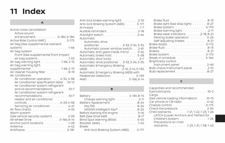
11 IndexA
Active noise cancellationActive soundenhancement . . . . . . . . . .5-184, 5-184
Active Ride Control (ARC). . . . . . . . . .5-175Air bag (See supplemental restraintsystem) . . . . . . . . . . . . . . . . . . . . .1-46Air bag system
Front (See supplemental front impactair bag system) . . . . . . . . . . . . . .1-53
Air bag warning light. . . . . . . . . .1-66, 2-15Air bag warning light,supplemental . . . . . . . . . . . . . .1-66, 2-15Air cleaner housing filter . . . . . . . . . .8-19Air conditioner
Air conditioner operation . . . .4-32, 4-38Air conditioner specification label . .10-12Air conditioner system refrigerantand oil recommendations . . . . . . .10-7Air conditioner system refrigerantrecommendations . . . . . . . . . . . .10-7Heater and air conditionercontrols . . . . . . . . . . . . . . .4-29, 4-38Servicing air conditioner . . . . . . . .4-41
Air flow charts . . . . . . . . . . . . . . . . .4-33Alarm system(See vehicle security system) . . . . . . .2-39All-Wheel Drive. . . . . . . . . . . . .5-166, 6-14Anchor point locations . . . . . . . . . . .1-28Antenna . . . . . . . . . . . . . . . . . . . .4-42Antifreeze . . . . . . . . . . . . . . . . . . .5-181
Anti-lock brake warning light. . . . . . . .2-10Anti-lock Braking System (ABS) . . . . . .5-171Armrests . . . . . . . . . . . . . . . . . . . . .1-7Audible reminders . . . . . . . . . . . . . .2-18Autolight switch . . . . . . . . . . . . . . .2-44Automatic
Automatic drivepositioner . . . . . . . . . . .3-33, 3-34, 3-35Automatic power window switch . . .2-61
Automatic anti-glare inside mirror . . . .3-32Automatic brake hold . . . . . . . . . . . .5-28Automatic door locks . . . . . . . . . . . . .3-7Automatic drive positioner . .3-33, 3-34, 3-35Automatic Emergency Braking(AEB) . . . . . . . . . . . . . . . .2-10, 2-14, 5-130Automatic Emergency Braking (AEB) withPedestrian Detection . . . . . . . . . . . .5-139AWD . . . . . . . . . . . . . . . . . . .5-166, 6-14
B
Battery . . . . . . . . . . . . . . . . .5-181, 8-15Charge warning light . . . . . . . . . . .2-11
Battery replacement . . . . . . . . . . . .8-24Key fob . . . . . . . . . . . . . . . . . . .8-24NISSAN Intelligent Key® . . . . . . . . .8-25
Before starting the engine . . . . . . . . .5-16Belt (See drive belt) . . . . . . . . . . . . . .8-17Blind Spot Warning (BSW) . . . . . . . . . .5-45Booster seats . . . . . . . . . . . . . . . . .1-42Brake
Anti-lock Braking System (ABS) . . . .5-171
Brake fluid . . . . . . . . . . . . . . . . .8-13Brake light (See stop light) . . . . . . .8-27Brake system. . . . . . . . . . . . . . .5-170Brake warning light . . . . . . . . . . . .2-11Brake wear indicators . . . . . . .2-18, 8-21Parking brake operation . . . . . . . .5-25Self-adjusting brakes . . . . . . . . . .8-21
Brake Assist. . . . . . . . . . . . . . . . . .5-172Brake fluid . . . . . . . . . . . . . . . . . . .8-13Brakes. . . . . . . . . . . . . . . . . . . . . .8-21Brake system. . . . . . . . . . . . . . . . .5-170Break-in schedule. . . . . . . . . . . . . .5-164Brightness control
Instrument panel. . . . . . . . . . . . .2-49Bulb check/instrument panel . . . . . . .2-10Bulb replacement . . . . . . . . . . . . . .8-27
C
Capacities and recommendedfuel/lubricants. . . . . . . . . . . . . . . . .10-2Cargo(See vehicle loading information). . . . .10-13Car phone or CB radio . . . . . . . . . . .4-42Chassis control . . . . . . . . . . . . . . .5-175Check tire pressure . . . . . . . . . . . . .2-34Child restraints . . . . . . .1-21, 1-22, 1-23, 1-26
LATCH (Lower Anchors and Tethers forCHildren) System . . . . . . . . . . . . .1-26Precautions on childrestraints . . . . . . . . .1-23, 1-31, 1-38, 1-43
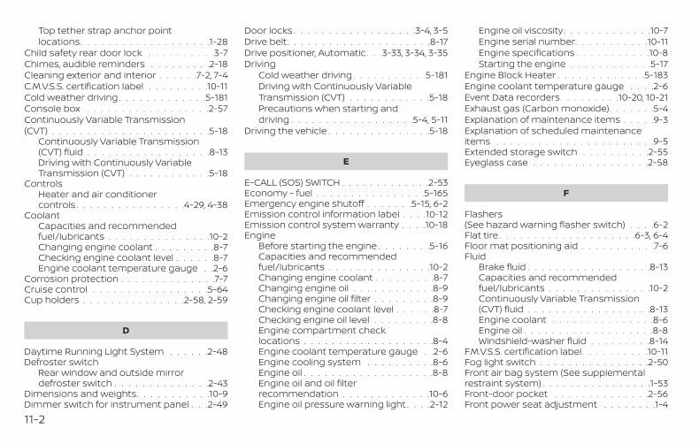
Top tether strap anchor pointlocations. . . . . . . . . . . . . . . . . . .1-28
Child safety rear door lock . . . . . . . . . .3-7Chimes, audible reminders . . . . . . . . .2-18Cleaning exterior and interior . . . . . .7-2, 7-4C.M.V.S.S. certification label . . . . . . . . .10-11Cold weather driving . . . . . . . . . . . . .5-181Console box . . . . . . . . . . . . . . . . . .2-57Continuously Variable Transmission(CVT) . . . . . . . . . . . . . . . . . . . . . . .5-18
Continuously Variable Transmission(CVT) fluid . . . . . . . . . . . . . . . . . .8-13Driving with Continuously VariableTransmission (CVT) . . . . . . . . . . . .5-18
ControlsHeater and air conditionercontrols . . . . . . . . . . . . . . . .4-29, 4-38
CoolantCapacities and recommendedfuel/lubricants . . . . . . . . . . . . . . .10-2Changing engine coolant . . . . . . . . .8-7Checking engine coolant level . . . . . .8-7Engine coolant temperature gauge . .2-6
Corrosion protection . . . . . . . . . . . . . .7-7Cruise control . . . . . . . . . . . . . . . . .5-64Cup holders . . . . . . . . . . . . . . .2-58, 2-59
D
Daytime Running Light System . . . . . .2-48Defroster switch
Rear window and outside mirrordefroster switch . . . . . . . . . . . . . .2-43
Dimensions and weights. . . . . . . . . . .10-9Dimmer switch for instrument panel . . .2-49
Door locks . . . . . . . . . . . . . . . . . .3-4, 3-5Drive belt. . . . . . . . . . . . . . . . . . . . .8-17Drive positioner, Automatic. . .3-33, 3-34, 3-35Driving
Cold weather driving . . . . . . . . . . .5-181Driving with Continuously VariableTransmission (CVT) . . . . . . . . . . . .5-18Precautions when starting anddriving . . . . . . . . . . . . . . . . . .5-4, 5-11
Driving the vehicle . . . . . . . . . . . . . . .5-18
E
E-CALL (SOS) SWITCH . . . . . . . . . . . . .2-53Economy - fuel . . . . . . . . . . . . . . . .5-165Emergency engine shutoff . . . . . . .5-15, 6-2Emission control information label . . . .10-12Emission control system warranty . . . .10-18Engine
Before starting the engine . . . . . . . .5-16Capacities and recommendedfuel/lubricants . . . . . . . . . . . . . . .10-2Changing engine coolant . . . . . . . . .8-7Changing engine oil . . . . . . . . . . . .8-9Changing engine oil filter . . . . . . . . .8-9Checking engine coolant level . . . . . .8-7Checking engine oil level . . . . . . . . .8-8Engine compartment checklocations . . . . . . . . . . . . . . . . . . .8-4Engine coolant temperature gauge . .2-6Engine cooling system . . . . . . . . . .8-6Engine oil . . . . . . . . . . . . . . . . . . .8-8Engine oil and oil filterrecommendation . . . . . . . . . . . . .10-6Engine oil pressure warning light . . . .2-12
Engine oil viscosity. . . . . . . . . . . . .10-7Engine serial number. . . . . . . . . . .10-11Engine specifications . . . . . . . . . . .10-8Starting the engine . . . . . . . . . . . .5-17
Engine Block Heater . . . . . . . . . . . . .5-183Engine coolant temperature gauge . . . .2-6Event Data recorders. . . . . . . . .10-20, 10-21Exhaust gas (Carbon monoxide). . . . . . .5-4Explanation of maintenance items . . . . .9-3Explanation of scheduled maintenanceitems . . . . . . . . . . . . . . . . . . . . . . .9-5Extended storage switch . . . . . . . . . .2-55Eyeglass case . . . . . . . . . . . . . . . . .2-58
F
Flashers(See hazard warning flasher switch) . . . .6-2Flat tire . . . . . . . . . . . . . . . . . . . .6-3, 6-4Floor mat positioning aid . . . . . . . . . . .7-6Fluid
Brake fluid . . . . . . . . . . . . . . . . . .8-13Capacities and recommendedfuel/lubricants . . . . . . . . . . . . . . .10-2Continuously Variable Transmission(CVT) fluid . . . . . . . . . . . . . . . . . .8-13Engine coolant . . . . . . . . . . . . . . .8-6Engine oil . . . . . . . . . . . . . . . . . . .8-8Windshield-washer fluid . . . . . . . . .8-14
F.M.V.S.S. certification label. . . . . . . . . .10-11Fog light switch . . . . . . . . . . . . . . . .2-50Front air bag system (See supplementalrestraint system) . . . . . . . . . . . . . . . .1-53Front-door pocket . . . . . . . . . . . . . .2-56Front power seat adjustment . . . . . . . .1-4
11-2
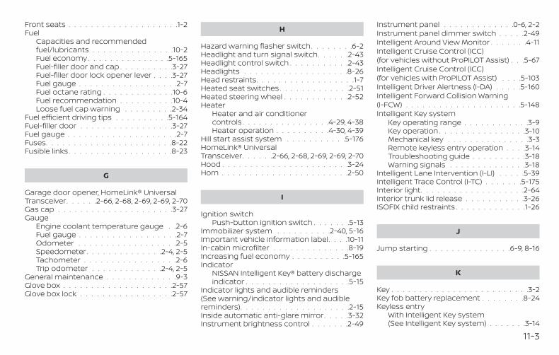
Front seats . . . . . . . . . . . . . . . . . . . .1-2Fuel
Capacities and recommendedfuel/lubricants . . . . . . . . . . . . . . .10-2Fuel economy . . . . . . . . . . . . . . .5-165Fuel-filler door and cap . . . . . . . . . .3-27Fuel-filler door lock opener lever . . . .3-27Fuel gauge . . . . . . . . . . . . . . . . . .2-7Fuel octane rating . . . . . . . . . . . . .10-6Fuel recommendation . . . . . . . . . .10-4Loose fuel cap warning . . . . . . . . .2-34
Fuel efficient driving tips . . . . . . . . . .5-164Fuel-filler door . . . . . . . . . . . . . . . . .3-27Fuel gauge . . . . . . . . . . . . . . . . . . . .2-7Fuses. . . . . . . . . . . . . . . . . . . . . . .8-22Fusible links. . . . . . . . . . . . . . . . . . .8-23
G
Garage door opener, HomeLink® UniversalTransceiver. . . . . .2-66, 2-68, 2-69, 2-69, 2-70Gas cap . . . . . . . . . . . . . . . . . . . . .3-27Gauge
Engine coolant temperature gauge . .2-6Fuel gauge . . . . . . . . . . . . . . . . . .2-7Odometer . . . . . . . . . . . . . . . . . .2-5Speedometer. . . . . . . . . . . . . .2-4, 2-5Tachometer . . . . . . . . . . . . . . . . .2-6Trip odometer . . . . . . . . . . . . .2-4, 2-5
General maintenance . . . . . . . . . . . . .9-3Glove box . . . . . . . . . . . . . . . . . . . .2-57Glove box lock . . . . . . . . . . . . . . . . .2-57
H
Hazard warning flasher switch. . . . . . . .6-2Headlight and turn signal switch. . . . . .2-43Headlight control switch . . . . . . . . . . .2-43Headlights . . . . . . . . . . . . . . . . . . .8-26Head restraints. . . . . . . . . . . . . . . . . .1-7Heated seat switches . . . . . . . . . . . . .2-51Heated steering wheel . . . . . . . . . . . .2-52Heater
Heater and air conditionercontrols . . . . . . . . . . . . . . . .4-29, 4-38Heater operation . . . . . . . . . .4-30, 4-39
Hill start assist system . . . . . . . . . . .5-176HomeLink® UniversalTransceiver. . . . . .2-66, 2-68, 2-69, 2-69, 2-70Hood . . . . . . . . . . . . . . . . . . . . . . .3-24Horn . . . . . . . . . . . . . . . . . . . . . . .2-50
I
Ignition switchPush-button ignition switch . . . . . . .5-13
Immobilizer system . . . . . . . . . .2-40, 5-16Important vehicle information label. . . .10-11In-cabin microfilter . . . . . . . . . . . . . .8-19Increasing fuel economy . . . . . . . . . .5-165Indicator
NISSAN Intelligent Key® battery dischargeindicator . . . . . . . . . . . . . . . . . . .5-15
Indicator lights and audible reminders(See warning/indicator lights and audiblereminders). . . . . . . . . . . . . . . . . . . .2-15Inside automatic anti-glare mirror. . . . .3-32Instrument brightness control . . . . . . .2-49
Instrument panel . . . . . . . . . . . . .0-6, 2-2Instrument panel dimmer switch . . . . .2-49Intelligent Around View Monitor . . . . . . .4-11Intelligent Cruise Control (ICC)(for vehicles without ProPILOT Assist) . . .5-67Intelligent Cruise Control (ICC)(for vehicles with ProPILOT Assist) . . . .5-103Intelligent Driver Alertness (I-DA) . . . . .5-160Intelligent Forward Collision Warning(I-FCW) . . . . . . . . . . . . . . . . . . . . .5-148Intelligent Key system
Key operating range . . . . . . . . . . . .3-9Key operation . . . . . . . . . . . . . . . .3-10Mechanical key . . . . . . . . . . . . . . .3-3Remote keyless entry operation . . . .3-14Troubleshooting guide . . . . . . . . . .3-18Warning signals . . . . . . . . . . . . . .3-18
Intelligent Lane Intervention (I-LI) . . . . .5-39Intelligent Trace Control (I-TC) . . . . . . .5-175Interior light. . . . . . . . . . . . . . . . . . .2-64Interior trunk lid release . . . . . . . . . . .3-26ISOFIX child restraints . . . . . . . . . . . . .1-26
J
Jump starting . . . . . . . . . . . . . . .6-9, 8-16
K
Key . . . . . . . . . . . . . . . . . . . . . . . . .3-2Key fob battery replacement . . . . . . . .8-24Keyless entry
With Intelligent Key system(See Intelligent Key system) . . . . . . .3-14
11-3
KeysNISSAN Intelligent Key® . . . . . . . . . .3-2NISSAN Vehicle Immobilizer Systemkeys . . . . . . . . . . . . . . . . . . . . . .3-4
L
LabelTire and Loading Information label . .10-12
LabelsAir conditioner specification label . . .10-12C.M.V.S.S. certification label . . . . . . .10-11Emission control information label . .10-12Engine serial number. . . . . . . . . . .10-11F.M.V.S.S. certification label. . . . . . . .10-11Tire and Loading Information label . .10-12Vehicle identification number (VIN) . .10-10Vehicle identification number (VIN)plate . . . . . . . . . . . . . . . . . . . . .10-10Warning labels (for SRS) . . . . . . . . .1-66
Lane Departure Warning (LDW) . . . . . . .5-34LATCH (Lower Anchors and Tethers forCHildren) System. . . . . . . . . . . . . . . .1-26License plate
Installing the license plate . . . . . . .10-13Light
Air bag warning light . . . . . . . .1-66, 2-15Brake light (See stop light) . . . . . . . .8-27Bulb check/instrument panel . . . . . .2-10Bulb replacement . . . . . . . . . . . . .8-27Charge warning light . . . . . . . . . . .2-11Exterior and Interior lights . . . . . . . .8-27Fog lights . . . . . . . . . . . . . . . . . .8-27Fog light switch . . . . . . . . . . . . . .2-50Headlight and turn signal switch. . . .2-43
Headlight control switch . . . . . . . . .2-43Headlights . . . . . . . . . . . . . . . . .8-26Interior light. . . . . . . . . . . . . . . . .2-64Light bulbs . . . . . . . . . . . . . . . . .8-26Low tire pressure warning light . . . . .2-12Low windshield-washer fluid warninglight. . . . . . . . . . . . . . . . . . . . . .2-34Personal lights . . . . . . . . . . . . . . .2-65Security indicator light . . . . . . . . . .2-17Spotlights (See map light) . . . . . . . .2-65Trunk light. . . . . . . . . . . . . . . . . .2-65Warning/indicator lights and audiblereminders . . . . . . . . . . . . . . . . . .2-15
Lights . . . . . . . . . . . . . . . . . . . . . .8-26Map lights . . . . . . . . . . . . . . . . . .2-65
LockChild safety rear door lock . . . . . . . .3-7Door locks . . . . . . . . . . . . . . . .3-4, 3-5Fuel-filler door lock opener lever . . . .3-27Glove box lock . . . . . . . . . . . . . . .2-57Power door locks . . . . . . . . . . . . . .3-6Trunk lid lock opener lever. . . . . . . .3-25
Loose fuel cap warning . . . . . . . . . . .2-34Low fuel warning light . . . . . . . . .2-14, 2-34Low tire pressure warning light . . . . . . .2-12Low windshield-washer fluid warninglight. . . . . . . . . . . . . . . . . . . . . . . .2-34Luggage(See vehicle loading information) . . . . .10-13
M
MaintenanceGeneral maintenance . . . . . . . . . . .9-3Inside the vehicle . . . . . . . . . . . . . .9-4
Maintenance precautions. . . . . . . . .8-2Outside the vehicle . . . . . . . . . . . . .9-3Seat belt maintenance . . . . . . . . . .1-20Under the hood and vehicle . . . . . . .9-4
Maintenance log. . . . . . . . . . . . . . . .9-20Maintenance requirements. . . . . . . . . .9-2Maintenance schedules . . . . . . . . .9-7, 9-7Maintenance under severe operationconditions. . . . . . . . . . . . . . . . .9-14, 9-19Malfunction indicator light . . . . . . . . . .2-16Manual front seat adjustment . . . . . . . .1-3Map lights . . . . . . . . . . . . . . . . . . . .2-65Memory Seat . . . . . . . . . . .3-33, 3-34, 3-35Meters and gauges. . . . . . . . . . . . . . .2-4
Instrument brightness control . . . . .2-49Mirror
Automatic anti-glare inside mirror. . .3-32Outside mirrors . . . . . . . . . . . . . .3-32Rearview . . . . . . . . . . . . . . . . . . .3-31Vanity mirror . . . . . . . . . . . . . . . .3-31
Mirrors . . . . . . . . . . . . . . . . . . . . . .3-31Moonroof. . . . . . . . . . . . . . . . . .2-62, 7-5Moving Object Detection (MOD) . . . . . .4-23
N
NissanConnect® Owner's Manual . . . . . .4-2NISSAN Intelligent Key® . . . . . . . . . . . .3-2NISSAN Intelligent Key® battery dischargeindicator . . . . . . . . . . . . . . . . . . . . .5-15NISSAN Vehicle ImmobilizerSystem . . . . . . . . . . . . . . . . . .2-40, 5-16
11-4
O
Octane rating (See fuel octane rating) . .10-6Odometer . . . . . . . . . . . . . . . . . . . .2-5Oil
Capacities and recommendedfuel/lubricants . . . . . . . . . . . . . . .10-2Changing engine oil . . . . . . . . . . . .8-9Changing engine oil filter . . . . . . . . .8-9Checking engine oil level . . . . . . . . .8-8Engine oil . . . . . . . . . . . . . . . . . . .8-8Engine oil and oil filterrecommendation . . . . . . . . . . . . .10-6Engine oil viscosity. . . . . . . . . . . . .10-7
Outside mirrors . . . . . . . . . . . . . . . .3-32Overhead sunglasses holder . . . . . . . .2-58Overheat
If your vehicle overheats . . . . . . . . .6-11Owner's manual order form . . . . . . . .10-22Owner's manual/service manual orderinformation . . . . . . . . . . . . . . . . . .10-22
P
ParkingParking brake operation . . . . . . . . .5-25Parking/parking on hills. . . . . . . . .5-169
Parking brake . . . . . . . . . . .2-12, 2-15, 5-25Personal lights . . . . . . . . . . . . . . . . .2-65Power
Power door locks . . . . . . . . . . . . . .3-6Power outlet . . . . . . . . . . . . . . . .2-54Power rear windows . . . . . . . . . . .2-61Power steering system . . . . . . . . .5-169Power windows . . . . . . . . . . . . . .2-60
Rear power windows . . . . . . . . . . .2-61Power outlet . . . . . . . . . . . . . . . . . .2-54Power steering . . . . . . . . . . . . . . . .5-169Precautions
Maintenance precautions. . . . . . . . .8-2Precautions on boosterseats . . . . . . . . . . . .1-23, 1-31, 1-38, 1-43Precautions on childrestraints . . . . . . . . .1-23, 1-31, 1-38, 1-43Precautions on seat belt usage . . . . .1-12Precautions on supplemental restraintsystem . . . . . . . . . . . . . . . . . . . .1-46Precautions when starting anddriving . . . . . . . . . . . . . . . . . .5-4, 5-11
ProPILOT Assist. . . . . . . . . . . . . . . . .5-91Push starting . . . . . . . . . . . . . . . . . .6-11
R
RadioCar phone or CB radio . . . . . . . . . .4-42
Readiness for inspection maintenance(I/M) test . . . . . . . . . . . . . . . . . . . .10-20Rear Automatic Braking (RAB) . . . . . . .5-125Rear Cross Traffic Alert (RCTA) . . . . . . .5-55Rear Door Alert . . . . . . . . . .2-36, 2-37, 2-53Rear power windows . . . . . . . . . . . . .2-61Rear seat . . . . . . . . . . . . . . . . . . . . .1-5Rear Sonar System (RSS) . . . . . . . . . .5-176Rearview mirror . . . . . . . . . . . . . . . .3-31RearView Monitor . . . . . . . . . . . . . . . .4-3Rear window and outside mirror defrosterswitch . . . . . . . . . . . . . . . . . . . . . .2-43Recommended Fluids . . . . . . . . . . . .10-2
RecordersEvent Data . . . . . . . . . . . . .10-20, 10-21
Refrigerant recommendation . . . . . . . .10-7Registering a vehicle in anothercountry . . . . . . . . . . . . . . . . . . . . .10-10Remote Engine Start . . . . . . . . . .3-21, 5-18Reporting safety defects (US only) . . . .10-19
S
SafetyChild safety rear door lock . . . . . . . .3-7Child seat belts . . . . . .1-23, 1-31, 1-38, 1-43Reporting safety defects (US only) . .10-19
Seat adjustmentFront manual seat adjustment . . . . . .1-3Front power seat adjustment . . . . . .1-4Rear seat adjustment . . . . . . . . . . .1-5
Seatback pockets . . . . . . . . . . . . . . .2-56Seat belt
Child safety . . . . . . . . . . . . . . . . .1-21Infants and small children . . . . . . . .1-22Injured Person. . . . . . . . . . . . . . . .1-15Larger children . . . . . . . . . . . . . . .1-22Precautions on seat belt usage . . . . .1-12Pregnant women. . . . . . . . . . . . . .1-15Seat belt extenders . . . . . . . . . . . .1-20Seat belt maintenance . . . . . . . . . .1-20Seat belts . . . . . . . . . . . . . . . .1-12, 7-7Shoulder belt height adjustment . . . .1-19Three-point type with retractor . . . . .1-15
Seat belt extenders . . . . . . . . . . . . . .1-20Seat belt warning light . . . . . . . . .1-14, 2-14Seats
Adjustment . . . . . . . . . . . . . . . . . .1-2
11-5
Armrests . . . . . . . . . . . . . . . . . . .1-7Automatic drivepositioner . . . . . . . . . . .3-33, 3-34, 3-35Front seats . . . . . . . . . . . . . . . . . .1-2Manual front seat adjustment . . . . . .1-3Rear seat . . . . . . . . . . . . . . . . . . .1-5
Security indicator light . . . . . . . . . . . .2-17Security system (NISSAN Vehicle ImmobilizerSystem), engine start. . . . . . . . . .2-40, 5-16Security systems
Vehicle security system . . . . . . . . .2-39Self-adjusting brakes . . . . . . . . . . . . .8-21Service manual order form. . . . . . . . .10-22Servicing air conditioner . . . . . . . . . . .4-41Shifting
Continuously Variable Transmission(CVT) . . . . . . . . . . . . . . . . . . . . .5-20
Shift lever lock release . . . . . . . . . . . .5-23Shoulder belt height adjustment . . . . . .1-19Sonar
Rear system . . . . . . . . . . . . . . . .5-176Spark plug replacement . . . . . . . . . . .8-18Spark plugs . . . . . . . . . . . . . . . . . . .8-18Specifications . . . . . . . . . . . . . . . . .10-8Speedometer. . . . . . . . . . . . . . . .2-4, 2-5Speedometer and odometer . . . . . . . .2-4Spotlights (See map light) . . . . . . . . . .2-65SRS warning label . . . . . . . . . . . . . . .1-66Stability control . . . . . . . . . . . . . . . .5-172Standard maintenance . . . . . . . .9-10, 9-15Starting
Before starting the engine . . . . . . . .5-16Jump starting . . . . . . . . . . . . .6-9, 8-16Precautions when starting anddriving . . . . . . . . . . . . . . . . . .5-4, 5-11Push starting . . . . . . . . . . . . . . . .6-11
Starting the engine . . . . . . . . . . . .5-17Starting the engine . . . . . . . . . . . . . .5-17Steering
Heated steering wheel . . . . . . . . . .2-52Power steering system . . . . . . . . .5-169
Steering Assist switch(for vehicles with ProPILOT Assist) . . . . .2-52Steering wheel . . . . . . . . . . . . . . . . .3-29Stop light . . . . . . . . . . . . . . . . . . . .8-27Storage . . . . . . . . . . . . . . . . . . . . .2-56Sunglasses case. . . . . . . . . . . . . . . .2-58Sunglasses holder . . . . . . . . . . . . . .2-58Sunroof . . . . . . . . . . . . . . . . . . . . . .7-5Sunroof (see Moonroof) . . . . . . . . . . .2-62Sun visors . . . . . . . . . . . . . . . . . . . .3-30Supplemental air bag warninglight. . . . . . . . . . . . . . . . . . . . .1-66, 2-15Supplemental front impact air bagsystem . . . . . . . . . . . . . . . . . . . . . .1-53Supplemental restraint system
Information and warning labels . . . .1-66Precautions on supplemental restraintsystem . . . . . . . . . . . . . . . . . . . .1-46
Supplemental restraint system(Supplemental air bag system) . . . . . . .1-46Switch
Autolight switch . . . . . . . . . . . . . .2-44Automatic power window switch . . .2-61Fog light switch . . . . . . . . . . . . . .2-50Hazard warning flasher switch. . . . . .6-2Headlight and turn signal switch. . . .2-43Headlight control switch . . . . . . . . .2-43Instrument brightness control . . . . .2-49Power door lock switch . . . . . . . . . .3-6Rear window and outside mirrordefroster switch . . . . . . . . . . . . . .2-43
Turn signal switch . . . . . . . . . . . . .2-49
T
Tachometer . . . . . . . . . . . . . . . . . . .2-6Temperature gauge
Engine coolant temperature gauge . .2-6Theft (NISSAN Vehicle Immobilizer System),engine start . . . . . . . . . . . . . . .2-40, 5-16Three-way catalyst . . . . . . . . . . . . . . .5-4Tilt
Telescopic steering . . . . . . . . . . . .3-30Tire
Flat tire . . . . . . . . . . . . . . . . . .6-3, 6-4Spare tire . . . . . . . . . . . . . . .6-5, 8-42Tire and Loading Information label . .10-12Tire chains . . . . . . . . . . . . . . . . .8-37Tire pressure . . . . . . . . . . . . . . . .8-30Tire rotation . . . . . . . . . . . . . . . .8-39Types of tires . . . . . . . . . . . . . . . .8-36Uniform tire quality grading. . . . . . .10-17Wheels and tires . . . . . . . . . . . . . .8-30Wheel/tire size . . . . . . . . . . . . . . .10-9
Tire pressureLow tire pressure warning light . . . . .2-12
Tire Pressure Monitoring System(TPMS) . . . . . . . . . . . . . . . . . . . .5-5, 6-3Towing
4-wheel drive models . . . . . . . . . . .6-13Flat towing . . . . . . . . . . . . . . . . .10-17Trailer towing . . . . . . . . . . . . . . .10-17
Towing a trailer . . . . . . . . . . . . . . . .10-17Towing your vehicle . . . . . . . . . . . . . .6-12Traffic Sign Recognition (TSR) . . . . . . . .5-31
11-6
TransceiverHomeLink® UniversalTransceiver. . . .2-66, 2-68, 2-69, 2-69, 2-70
TransmissionContinuously Variable Transmission (CVT)fluid . . . . . . . . . . . . . . . . . . . . . .8-13Driving with Continuously VariableTransmission (CVT) . . . . . . . . . . . .5-18
Transmission shift lever lock release . . .5-23Travel (See registering a vehicle in anothercountry). . . . . . . . . . . . . . . . . . . . .10-10Trip odometer . . . . . . . . . . . . . . .2-4, 2-5Trunk access through the rearseat . . . . . . . . . . . . . . . . . . . . .1-5, 3-26Trunk lid . . . . . . . . . . . . . . . . . . . . .3-25Trunk lid lock opener lever. . . . . . . . . .3-25Trunk light. . . . . . . . . . . . . . . . . . . .2-65Turn signal switch . . . . . . . . . . . . . . .2-49
U
Uniform tire quality grading. . . . . . . . .10-17USB/iPod® Charging Ports . . . . . . . . .4-42
V
Vanity mirror . . . . . . . . . . . . . . . . . .3-31Variable voltage control system . . . . . .8-17Vehicle dimensions and weights . . . . . .10-9Vehicle Dynamic Control (VDC)system . . . . . . . . . . . . . . . . . . . . .5-172Vehicle identification . . . . . . . . . . . . .10-10Vehicle identification number (VIN) . . . .10-10
Vehicle identification number (VIN)(Chassis number) . . . . . . . . . . . . . . .10-10Vehicle identification number (VIN)plate . . . . . . . . . . . . . . . . . . . . . . .10-10Vehicle immobilizer system. . . . . .2-40, 5-16Vehicle information display . . . . . . . . .2-19Vehicle loading information . . . . . . . .10-13Vehicle recovery . . . . . . . . . . . . . . . .6-14Vehicle security system . . . . . . . . . . .2-39Vehicle security system (NISSAN VehicleImmobilizer System), engine start . .2-40, 5-16Ventilators . . . . . . . . . . . . . . . . . . .4-28Visors . . . . . . . . . . . . . . . . . . . . . .3-30
W
WarningAir bag warning light . . . . . . . .1-66, 2-15Anti-lock brake warning light . . . . . .2-10Battery charge warning light . . . . . .2-11Brake warning light . . . . . . . . . . . .2-11Engine oil pressure warning light . . . .2-12Hazard warning flasher switch. . . . . .6-2Loose fuel cap warning . . . . . . . . .2-34Low fuel warning light . . . . . . .2-14, 2-34Low tire pressure warning light . . . . .2-12Low windshield-washer fluid warninglight. . . . . . . . . . . . . . . . . . . . . .2-34Seat belt warning light . . . . . . .1-14, 2-14Supplemental air bag warninglight. . . . . . . . . . . . . . . . . . .1-66, 2-15TPMS. . . . . . . . . . . . . . . . . . . . . .2-4Vehicle security system . . . . . . . . .2-39
Warning/indicator lights and audiblereminders . . . . . . . . . . . . . . . . . .2-15Warning labels (for SRS) . . . . . . . . .1-66
Warning/indicator lights and audiblereminders . . . . . . . . . . . . . . . . . . . .2-15
Audible reminders . . . . . . . . . . . . .2-15Indicator lights . . . . . . . . . . . . . . .2-15Warning lights . . . . . . . . . . . . . . .2-15
Warning lights . . . . . . . . . . . . . . . . .2-15Warning lights, indicator lights and audiblereminders . . . . . . . . . . . . . . . . . . . .2-9Weights (See dimensions and weights) . .10-9Wheels and tires . . . . . . . . . . . . . . . .8-30Wheel/tire size . . . . . . . . . . . . . . . . .10-9When traveling or registering in anothercountry . . . . . . . . . . . . . . . . . . . . .10-10Windows . . . . . . . . . . . . . . . . . . . .2-60
Locking passengers' windows . . . . .2-61Power rear windows . . . . . . . . . . .2-61Power windows . . . . . . . . . . . . . .2-60Rear power windows . . . . . . . . . . .2-61
Windshield-washer fluid . . . . . . . . . . .8-14Windshield wiper blades . . . . . . . . . . .8-20Wiper
Wiper blades . . . . . . . . . . . . . . . .8-20Wiper and washer switch . . . . . . . . . .2-42
11-7

MEMO

MEMO

MEMO
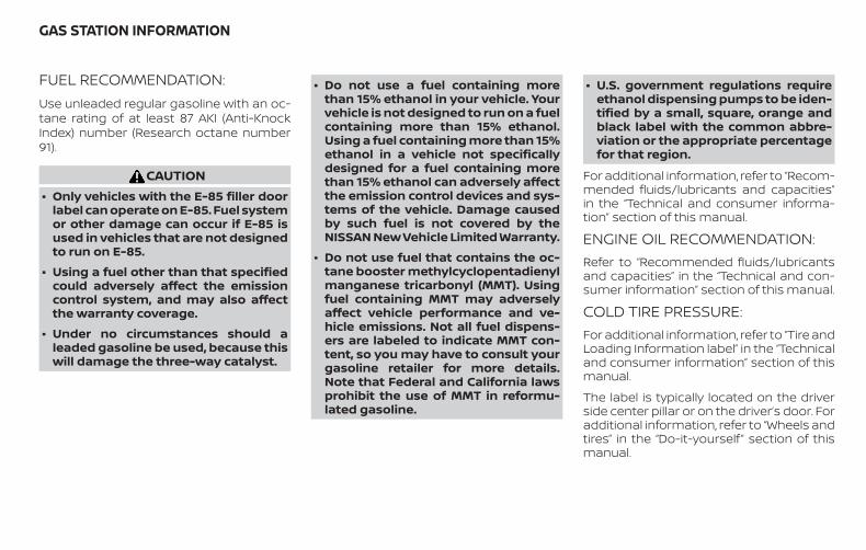
FUEL RECOMMENDATION:Use unleaded regular gasoline with an oc-tane rating of at least 87 AKI (Anti-KnockIndex) number (Research octane number91).
CAUTION∙ Only vehicles with the E-85 filler door
label can operate on E-85. Fuel systemor other damage can occur if E-85 isused in vehicles that are not designedto run on E-85.
∙ Using a fuel other than that specifiedcould adversely affect the emissioncontrol system, and may also affectthe warranty coverage.
∙ Under no circumstances should aleaded gasoline be used, because thiswill damage the three-way catalyst.
∙ Do not use a fuel containing morethan 15% ethanol in your vehicle. Yourvehicle is not designed to run on a fuelcontaining more than 15% ethanol.Using a fuel containing more than 15%ethanol in a vehicle not specificallydesigned for a fuel containing morethan 15% ethanol can adversely affectthe emission control devices and sys-tems of the vehicle. Damage causedby such fuel is not covered by theNISSAN New Vehicle Limited Warranty.
∙ Do not use fuel that contains the oc-tane booster methylcyclopentadienylmanganese tricarbonyl (MMT). Usingfuel containing MMT may adverselyaffect vehicle performance and ve-hicle emissions. Not all fuel dispens-ers are labeled to indicate MMT con-tent, so you may have to consult yourgasoline retailer for more details.Note that Federal and California lawsprohibit the use of MMT in reformu-lated gasoline.
∙ U.S. government regulations requireethanol dispensing pumps to be iden-tified by a small, square, orange andblack label with the common abbre-viation or the appropriate percentagefor that region.
For additional information, refer to “Recom-mended fluids/lubricants and capacities”in the “Technical and consumer informa-tion” section of this manual.
ENGINE OIL RECOMMENDATION:Refer to “Recommended fluids/lubricantsand capacities” in the “Technical and con-sumer information” section of this manual.
COLD TIRE PRESSURE:For additional information, refer to “Tire andLoading Information label” in the “Technicaland consumer information” section of thismanual.
The label is typically located on the driverside center pillar or on the driver’s door. Foradditional information, refer to “Wheels andtires” in the “Do-it-yourself ” section of thismanual.
GAS STATION INFORMATION
RECOMMENDED NEW VEHICLEBREAK-IN PROCEDURE:During the first 1,200 miles (2,000 km) ofvehicle use, follow the break-in procedurerecommendations for the future reliabilityand economy of your new vehicle. For ad-ditional information, refer to “Break-inschedule” in the “Starting and driving” sec-tion of this manual. Failure to follow theserecommendations may result in vehicledamage or shortened engine life.


L34-D
Printing : April 2019Publication No.:
Printed in the U.S.A.OM19EA 0L34U2
Owner’s Manual Supplement
The information contained within this supplement updates the followinginformation in the 2019 NISSAN Altima Owner’s Manual:
∙ “Supplemental Restraint System (SRS)” in the “Safety—Seats, seat beltsand supplemental restraint system” section.
Read carefully and keep in vehicle.
Printing: August 2018Publication No. SU19EA 2L34U0
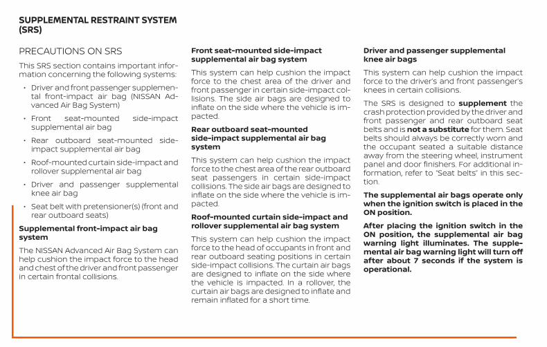
PRECAUTIONS ON SRSThis SRS section contains important infor-mation concerning the following systems:
∙ Driver and front passenger supplemen-tal front-impact air bag (NISSAN Ad-vanced Air Bag System)
∙ Front seat-mounted side-impactsupplemental air bag
∙ Rear outboard seat-mounted side-impact supplemental air bag
∙ Roof-mounted curtain side-impact androllover supplemental air bag
∙ Driver and passenger supplementalknee air bag
∙ Seat belt with pretensioner(s) (front andrear outboard seats)
Supplemental front-impact air bagsystem
The NISSAN Advanced Air Bag System canhelp cushion the impact force to the headand chest of the driver and front passengerin certain frontal collisions.
Front seat-mounted side-impactsupplemental air bag system
This system can help cushion the impactforce to the chest area of the driver andfront passenger in certain side-impact col-lisions. The side air bags are designed toinflate on the side where the vehicle is im-pacted.
Rear outboard seat-mountedside-impact supplemental air bagsystem
This system can help cushion the impactforce to the chest area of the rear outboardseat passengers in certain side-impactcollisions. The side air bags are designed toinflate on the side where the vehicle is im-pacted.
Roof-mounted curtain side-impact androllover supplemental air bag system
This system can help cushion the impactforce to the head of occupants in front andrear outboard seating positions in certainside-impact collisions. The curtain air bagsare designed to inflate on the side wherethe vehicle is impacted. In a rollover, thecurtain air bags are designed to inflate andremain inflated for a short time.
Driver and passenger supplementalknee air bags
This system can help cushion the impactforce to the driver’s and front passenger’sknees in certain collisions.
The SRS is designed to supplement thecrash protection provided by the driver andfront passenger and rear outboard seatbelts and is not a substitute for them. Seatbelts should always be correctly worn andthe occupant seated a suitable distanceaway from the steering wheel, instrumentpanel and door finishers. For additional in-formation, refer to “Seat belts” in this sec-tion.
The supplemental air bags operate onlywhen the ignition switch is placed in theON position.
After placing the ignition switch in theON position, the supplemental air bagwarning light illuminates. The supple-mental air bag warning light will turn offafter about 7 seconds if the system isoperational.
SUPPLEMENTAL RESTRAINT SYSTEM(SRS)
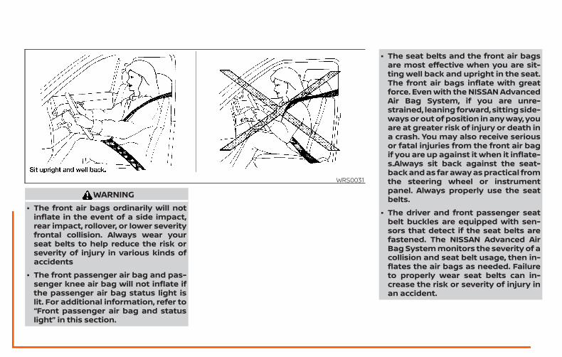
WARNING∙ The front air bags ordinarily will not
inflate in the event of a side impact,rear impact, rollover, or lower severityfrontal collision. Always wear yourseat belts to help reduce the risk orseverity of injury in various kinds ofaccidents
∙ The front passenger air bag and pas-senger knee air bag will not inflate ifthe passenger air bag status light islit. For additional information, refer to“Front passenger air bag and statuslight” in this section.
∙ The seat belts and the front air bagsare most effective when you are sit-ting well back and upright in the seat.The front air bags inflate with greatforce. Even with the NISSAN AdvancedAir Bag System, if you are unre-strained, leaning forward, sitting side-ways or out of position in any way, youare at greater risk of injury or death ina crash. You may also receive seriousor fatal injuries from the front air bagif you are up against it when it inflate-s.Always sit back against the seat-back and as far away as practical fromthe steering wheel or instrumentpanel. Always properly use the seatbelts.
∙ The driver and front passenger seatbelt buckles are equipped with sen-sors that detect if the seat belts arefastened. The NISSAN Advanced AirBag System monitors the severity of acollision and seat belt usage, then in-flates the air bags as needed. Failureto properly wear seat belts can in-crease the risk or severity of injury inan accident.
WRS0031
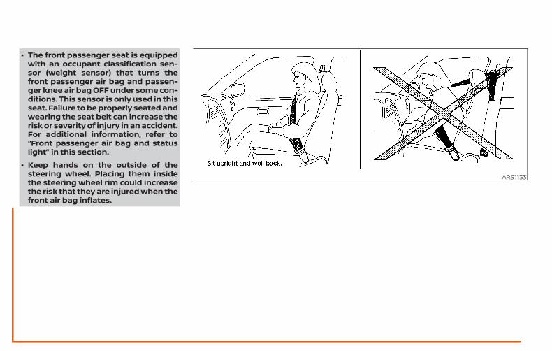
∙ The front passenger seat is equippedwith an occupant classification sen-sor (weight sensor) that turns thefront passenger air bag and passen-ger knee air bag OFF under some con-ditions. This sensor is only used in thisseat. Failure to be properly seated andwearing the seat belt can increase therisk or severity of injury in an accident.For additional information, refer to“Front passenger air bag and statuslight” in this section.
∙ Keep hands on the outside of thesteering wheel. Placing them insidethe steering wheel rim could increasethe risk that they are injured when thefront air bag inflates.
ARS1133
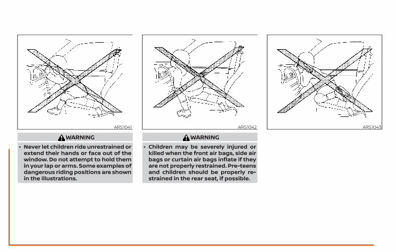
WARNING∙ Never let children ride unrestrained or
extend their hands or face out of thewindow. Do not attempt to hold themin your lap or arms. Some examples ofdangerous riding positions are shownin the illustrations.
WARNING∙ Children may be severely injured or
killed when the front air bags, side airbags or curtain air bags inflate if theyare not properly restrained. Pre-teensand children should be properly re-strained in the rear seat, if possible.
ARS1041 ARS1042 ARS1043
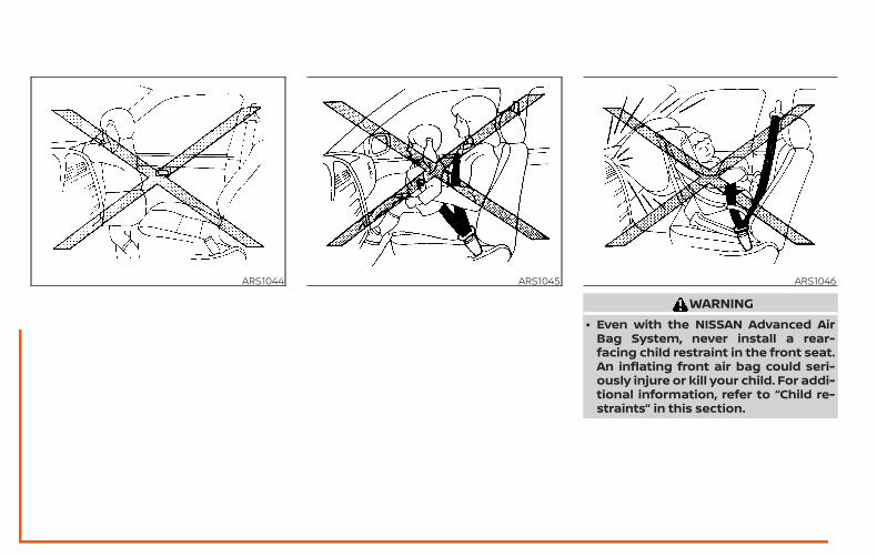
WARNING∙ Even with the NISSAN Advanced Air
Bag System, never install a rear-facing child restraint in the front seat.An inflating front air bag could seri-ously injure or kill your child. For addi-tional information, refer to “Child re-straints” in this section.
ARS1044 ARS1045 ARS1046
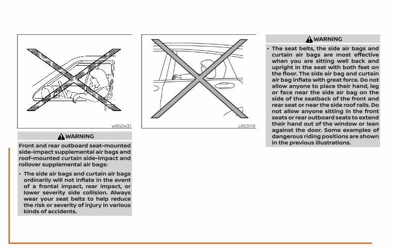
WARNINGFront and rear outboard seat-mountedside-impact supplemental air bags androof-mounted curtain side-impact androllover supplemental air bags:
∙ The side air bags and curtain air bagsordinarily will not inflate in the eventof a frontal impact, rear impact, orlower severity side collision. Alwayswear your seat belts to help reducethe risk or severity of injury in variouskinds of accidents.
WARNING∙ The seat belts, the side air bags and
curtain air bags are most effectivewhen you are sitting well back andupright in the seat with both feet onthe floor. The side air bag and curtainair bag inflate with great force. Do notallow anyone to place their hand, legor face near the side air bag on theside of the seatback of the front andrear seat or near the side roof rails. Donot allow anyone sitting in the frontseats or rear outboard seats to extendtheir hand out of the window or leanagainst the door. Some examples ofdangerous riding positions are shownin the previous illustrations.
WRS0431 LRS3119
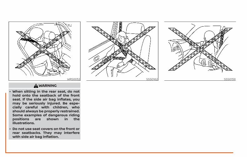
WARNING∙ When sitting in the rear seat, do not
hold onto the seatback of the frontseat. If the side air bag inflates, youmay be seriously injured. Be espe-cially careful with children, whoshould always be properly restrained.Some examples of dangerous ridingpositions are shown in theillustrations.
∙ Do not use seat covers on the front orrear seatbacks. They may interferewith side air bag inflation.
WRS0032 SSS0162 SSS0159
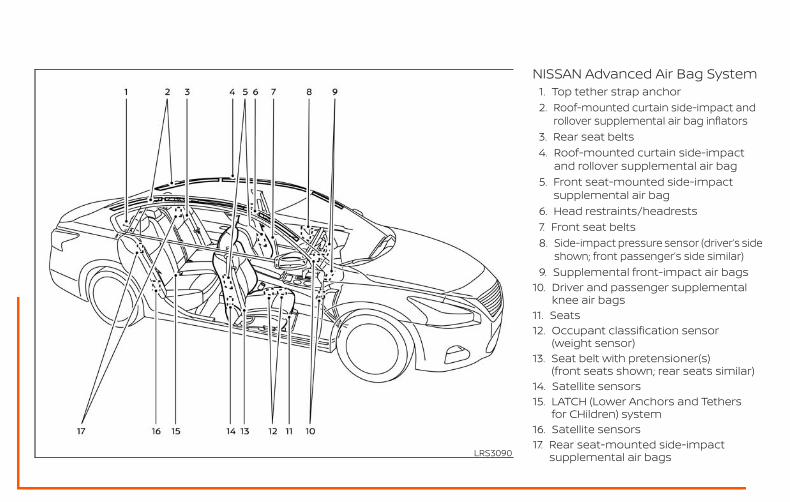
NISSAN Advanced Air Bag System1. Top tether strap anchor2. Roof-mounted curtain side-impact and
rollover supplemental air bag inflators3. Rear seat belts4. Roof-mounted curtain side-impact
and rollover supplemental air bag5. Front seat-mounted side-impact
supplemental air bag6. Head restraints/headrests7. Front seat belts8. Side-impact pressure sensor (driver’s side
shown; front passenger’s side similar)9. Supplemental front-impact air bags
10. Driver and passenger supplementalknee air bags
11. Seats12. Occupant classification sensor
(weight sensor)13. Seat belt with pretensioner(s)
(front seats shown; rear seats similar)14. Satellite sensors15. LATCH (Lower Anchors and Tethers
for CHildren) system16. Satellite sensors17. Rear seat-mounted side-impact
supplemental air bagsLRS3090
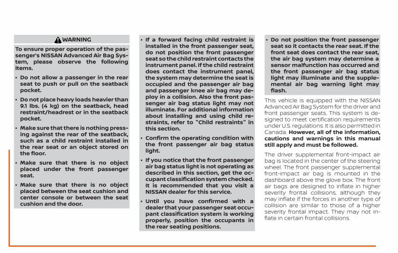
WARNINGTo ensure proper operation of the pas-senger’s NISSAN Advanced Air Bag Sys-tem, please observe the followingitems.
∙ Do not allow a passenger in the rearseat to push or pull on the seatbackpocket.
∙ Do not place heavy loads heavier than9.1 lbs. (4 kg) on the seatback, headrestraint/headrest or in the seatbackpocket.
∙ Make sure that there is nothing press-ing against the rear of the seatback,such as a child restraint installed inthe rear seat or an object stored onthe floor.
∙ Make sure that there is no objectplaced under the front passengerseat.
∙ Make sure that there is no objectplaced between the seat cushion andcenter console or between the seatcushion and the door.
∙ If a forward facing child restraint isinstalled in the front passenger seat,do not position the front passengerseat so the child restraint contacts theinstrument panel. If the child restraintdoes contact the instrument panel,the system may determine the seat isoccupied and the passenger air bagand passenger knee air bag may de-ploy in a collision. Also the front pas-senger air bag status light may notilluminate. For additional informationabout installing and using child re-straints, refer to "Child restraints" inthis section.
∙ Confirm the operating condition withthe front passenger air bag statuslight.
∙ If you notice that the front passengerair bag status light is not operating asdescribed in this section, get the oc-cupant classification system checked.It is recommended that you visit aNISSAN dealer for this service.
∙ Until you have confirmed with adealer that your passenger seat occu-pant classification system is workingproperly, position the occupants inthe rear seating positions.
∙ Do not position the front passengerseat so it contacts the rear seat. If thefront seat does contact the rear seat,the air bag system may determine asensor malfunction has occurred andthe front passenger air bag statuslight may illuminate and the supple-mental air bag warning light mayflash.
This vehicle is equipped with the NISSANAdvanced Air Bag System for the driver andfront passenger seats. This system is de-signed to meet certification requirementsunder U.S. regulations. It is also permitted inCanada. However, all of the information,cautions and warnings in this manualstill apply and must be followed.
The driver supplemental front-impact airbag is located in the center of the steeringwheel. The front passenger supplementalfront-impact air bag is mounted in thedashboard above the glove box. The frontair bags are designed to inflate in higherseverity frontal collisions, although theymay inflate if the forces in another type ofcollision are similar to those of a higherseverity frontal impact. They may not in-flate in certain frontal collisions.
Vehicle damage (or lack of it) is not alwaysan indication of proper front air bag systemoperation.
The NISSAN Advanced Air Bag Systemmonitors information from the crash zonesensor, the Air bag Control Unit (ACU), seatbelt buckle sensors and occupant classifi-cation sensor (weight sensor). Inflator op-eration is based on the severity of a colli-sion and seat belt usage for the driver. Forthe front passenger, the occupant classifi-cation sensor is also monitored. Based oninformation from the sensor, only one frontair bag may inflate in a crash, depending onthe crash severity and whether the frontoccupants are belted or unbelted. Addi-tionally, the front passenger air bag andpassenger knee air bag may be automati-cally turned off under some conditions, de-pending on the weight detected on thefront passenger seat and how the seat beltis used. If the front passenger air bag andpassenger knee air bag are OFF, the frontpassenger air bag status light will be illumi-nated. For additional information, refer to“Front passenger air bag and status light” inthis section. One front air bag inflating doesnot indicate improper performance of thesystem.
If you have any questions about your airbag system, it is recommended that youvisit a NISSAN dealer to obtain informationabout the system. If you are consideringmodification of your vehicle due to a dis-ability, you may also contact NISSAN. Con-tact information is contained in the front ofthis Owner’s Manual.
When a front air bag inflates, a fairly loudnoise may be heard, followed by the re-lease of smoke. This smoke is not harmfuland does not indicate a fire. Care should betaken to not inhale it, as it may cause irrita-tion and choking. Those with a history of abreathing condition should get fresh airpromptly.
Front air bags, along with the use of seatbelts, help to cushion the impact force onthe face and chest of the front occupants.They can help save lives and reduce seri-ous injuries. However, an inflating front airbag may cause facial abrasions or otherinjuries. Front air bags do not provide re-straint to the lower body.
Even with NISSAN Advanced Air Bags, seatbelts should be correctly worn and thedriver and front passenger seated uprightas far as practical away from the steeringwheel or instrument panel. The front airbags inflate quickly in order to help protectthe front occupants. Because of this, theforce of the front air bag inflating can in-crease the risk of injury if the occupant istoo close to, or is against, the front air bagmodule during inflation.
The front air bags deflate quickly after acollision.
The front air bags operate only when theignition switch is placed in the ON posi-tion.
After placing the ignition switch in theON position, the supplemental air bagwarning light illuminates. The supple-mental air bag warning light will turn offafter about 7 seconds if the system isoperational.
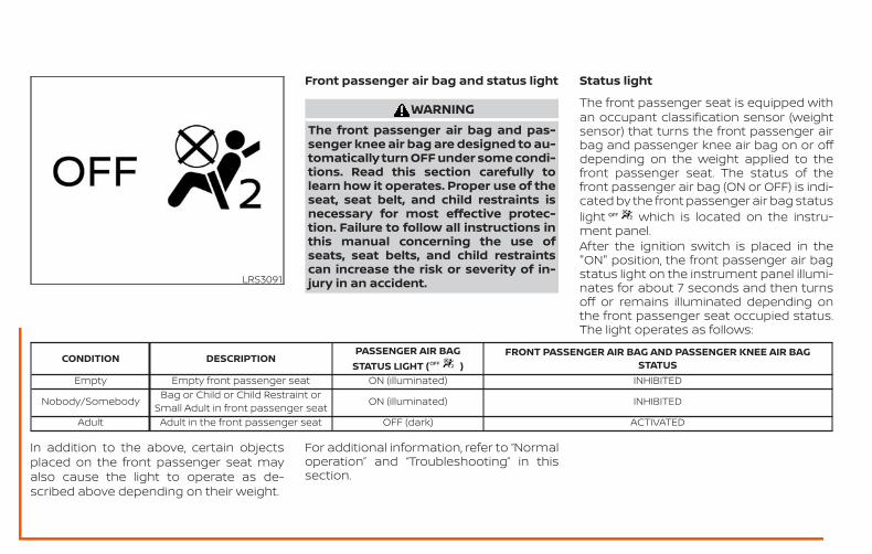
Front passenger air bag and status light
WARNINGThe front passenger air bag and pas-senger knee air bag are designed to au-tomatically turn OFF under some condi-tions. Read this section carefully tolearn how it operates. Proper use of theseat, seat belt, and child restraints isnecessary for most effective protec-tion. Failure to follow all instructions inthis manual concerning the use ofseats, seat belts, and child restraintscan increase the risk or severity of in-jury in an accident.
Status light
The front passenger seat is equipped withan occupant classification sensor (weightsensor) that turns the front passenger airbag and passenger knee air bag on or offdepending on the weight applied to thefront passenger seat. The status of thefront passenger air bag (ON or OFF) is indi-cated by the front passenger air bag statuslight which is located on the instru-ment panel.After the ignition switch is placed in the"ON" position, the front passenger air bagstatus light on the instrument panel illumi-nates for about 7 seconds and then turnsoff or remains illuminated depending onthe front passenger seat occupied status.The light operates as follows:
CONDITION DESCRIPTIONPASSENGER AIR BAG
STATUS LIGHT ( )FRONT PASSENGER AIR BAG AND PASSENGER KNEE AIR BAG
STATUSEmpty Empty front passenger seat ON (illuminated) INHIBITED
Nobody/Somebody Bag or Child or Child Restraint orSmall Adult in front passenger seat ON (illuminated) INHIBITED
Adult Adult in the front passenger seat OFF (dark) ACTIVATED
In addition to the above, certain objectsplaced on the front passenger seat mayalso cause the light to operate as de-scribed above depending on their weight.
For additional information, refer to “Normaloperation” and “Troubleshooting” in thissection.
LRS3091
Front passenger air bag
The front passenger air bag is designed toautomatically turn OFF when the vehicle isoperated under some conditions as de-scribed below in accordance with U.S. regu-lations. If the front passenger air bag is OFF,it will not inflate in a crash. The driver air bagand other air bags in your vehicle are notpart of this system.
The purpose of the regulation is to helpreduce the risk of injury or death from aninflating air bag to certain front passengerseat occupants, such as children, by requir-ing the air bag to be automatically turnedOFF. Certain sensors are used to meet therequirements.
The occupant classification sensor in thisvehicle is a weight sensor. It is designed todetect an occupant and objects on theseat by weight. For example, if a child is inthe front passenger seat, the NISSAN Ad-vanced Air Bag System is designed to turnthe front passenger air bag OFF in accor-dance with the regulations. Also, if a childrestraint of the type specified in the regula-tions is on the seat, its weight and thechild’s weight can be detected and causethe air bag to turn OFF.
Front passenger seat adult occupants whoare properly seated and using the seat beltas outlined in this manual should notcause the front passenger air bag and pas-senger knee air bag to be automaticallyturned OFF. For small adults it may beturned OFF, however if the occupant takeshis/her weight off the seat cushion (for ex-ample, by not sitting upright, by sitting onan edge of the seat, or by otherwise beingout of position), this could cause the sensorto turn the air bag OFF. Always be sure to beseated and wearing the seat belt properlyfor the most effective protection by theseat belt and supplemental air bag.
NISSAN recommends that pre-teens andchildren be properly restrained in a rearseat. NISSAN also recommends that ap-propriate child restraints and boosterseats be properly installed in a rear seat. Ifthis is not possible, the occupant classifica-tion sensor is designed to operate as de-scribed above to turn the front passengerair bag and passenger knee air bag OFF forspecified child restraints as required by theregulations. Failing to properly secure childrestraints and to use the ALR mode mayallow the restraint to tip or move in a colli-sion or sudden stop. This can also result inthe passenger air bag and passenger kneeair bag inflating in a crash instead of being
OFF. For additional information aboutproper use and installation, refer to “Childrestraints” in this section.
If the front passenger seat is not occupied,the front passenger air bag and passengerknee air bag are designed not to inflate in acrash. However, heavy objects placed onthe seat could result in air bag inflation,because of the object’s weight detected bythe occupant classification sensor. Otherconditions could also result in air bag infla-tion, such as if a child is standing on theseat, or if two children are on the seat, con-trary to the instructions in this manual. Al-ways be sure that you and all vehicle occu-pants are seated and restrained properly.
Using the front passenger air bag statuslight, you can monitor when the front pas-senger air bag and passenger knee air bagare automatically turned OFF.
If an adult occupant is in the seat but thefront passenger air bag status light is illu-minated (indicating that the front passen-ger air bag and passenger knee air bag areOFF), it could be that the person is a smalladult, or is not sitting on the seat properlyor not using the seat belt properly.
If a child restraint must be used in the frontseat, the front passenger air bag status
light may or may not be illuminated, de-pending on the size of the child and thetype of child restraint being used. If the airbag status light is not illuminated (indicat-ing that the air bag might inflate in a crash),it could be that the child restraint or seatbelt is not being used properly. Make surethat the child restraint is installed properly,the seat belt is used properly and the occu-pant is positioned properly. If the air bagstatus light is still not illuminated, reposi-tion the occupant or child restraint in a rearseat.
If the front passenger air bag status lightwill not illuminate even though you believethat the child restraint, the seat belts andthe occupant are properly positioned, it isrecommended that you take your vehicleto a NISSAN dealer. A NISSAN dealer cancheck system status by using a specialtool. However, until you have confirmedwith a dealer that your air bag is workingproperly, reposition the occupant or childrestraint in a rear seat.
The NISSAN Advanced Air Bag System andfront passenger air bag status light willtake a few seconds to register a change inthe front passenger seat status. This is nor-mal system operation and does not indi-cate a malfunction.
If a malfunction occurs in the front passen-ger air bag system, the supplemental airbag warning light , located in the me-ter and gauges area of the instrumentpanel, will be illuminated (blinking orsteadily lit). Have the system checked. It isrecommended that you visit a NISSANdealer for this service.
Normal operationIn order for the occupant classificationsensor system to classify the front passen-ger based on weight, please follow the pre-cautions and steps outlined below:
Precautions
∙ Make sure that there are no objectsweighing over 9.1 lbs. (4 kg) hanging onthe seat or placed in the seatbackpocket.
∙ Make sure that a child restraint or otherobject is not pressing against the rearof the seatback.
∙ Make sure that a rear passenger is notpushing or pulling on the back of thefront passenger seat.
∙ Make sure that the front passengerseat or seatback is not forced backagainst an object on the seat or floorbehind it.
∙ Make sure that there is no object placedunder the front passenger seat.
Steps
1. Adjust the seat as outlined in the “Seats”section of this manual. Sit upright, lean-ing against the seatback, and centeredon the seat cushion with your feet com-fortably extended to the floor.
2. Make sure there are no objects on yourlap.
3. Fasten the seat belt as outlined in the“Seat belts” section of this manual.Front passenger seat belt buckle sta-tus is monitored by the occupant clas-sification system, and is used as an in-put to determine occupancy status. So,it is highly recommended that the frontpassenger fasten their seat belt.
4. Remain in this position for 30 secondsallowing the system to classify thefront passenger before the vehicle isput into motion.
5. Ensure proper classification by check-ing the front passenger air bag statuslight.
NOTE:
This vehicle’s occupant classificationsensor system generally keeps the clas-sification locked during driving, so it isimportant that you confirm that thefront passenger is properly classifiedprior to driving. However, the occupantclassification sensor may recalculate theweight of the occupant under some con-ditions (both while driving and whenstopped), so front passenger seat occu-pants should continue to remain seatedas outlined above.
Troubleshooting
If you think the front passenger air bagstatus light is incorrect:
1. If the light is ON with an adult occupyingthe front passenger seat:
∙ Occupant is a small adult — the air baglight is functioning as intended. Thefront passenger air bag and passengerknee air bag is suppressed.
However, if the occupant is not a smalladult, then this may be due to the followingconditions that may be interfering with theweight sensors:
∙ Occupant is not sitting upright, leaningagainst the seatback, and centered onthe seat cushion with his/her feet com-fortably extended to the floor.
∙ A child restraint or other object pressingagainst the rear of the seatback.
∙ A rear passenger pushing or pulling onthe back of the front passenger seat.
∙ Forcing the front seat or seatbackagainst an object on the seat or floorbehind it.
∙ An object placed under the front pas-senger seat.
∙ An object placed between the seatcushion and center console or betweenthe seat cushion and the door.
If the vehicle is moving, please come to astop when it is safe to do so. Check andcorrect any of the above conditions. Re-start the vehicle and wait 1 minute.
NOTE:
A system check will be performed duringwhich the front passenger air bag statuslight will remain lit for about 7 secondsinitially.
If the light is still ON after this, the personshould be advised not to ride in the frontpassenger seat and the vehicle should bechecked as soon as possible. It is recom-mended that you visit a NISSAN dealer forthis service.
2. If the light is OFF with a small adult,child or child restraint occupying thefront passenger seat.
This may be due to the following con-ditions that may be interfering with theweight sensors:
∙ Small adult or child is not sitting upright,leaning against the seatback, and cen-tered on the seat cushion with his/herfeet comfortably extended to the floor.
∙ The child restraint is not properly in-stalled, as outlined in the “Child re-straints” section of this manual.
∙ An object weighing over 9.1 lbs. (4 kg)hanging on the seat or placed in theseatback pocket.
∙ A child restraint or other object pressingagainst the rear of the seatback.
∙ A rear passenger pushing or pulling onthe back of the front passenger seat.
∙ Forcing the front seat or seatbackagainst an object on the seat or floorbehind it.
∙ An object placed under the front pas-senger seat.
∙ An object placed between the seatcushion and center console.
If the vehicle is moving, please come to astop when it is safe to do so. Check andcorrect any of the above conditions. Re-start the vehicle and wait 1 minute.
NOTE:
A system check will be performed duringwhich the front passenger air bag statuslight will remain lit for about 7 secondsinitially.
If the light is still OFF after this, the smalladult, child or child restraint should be re-positioned in the rear seat and the vehicleshould be checked as soon as possible. It isrecommended that you visit a NISSANdealer for this service.
3. If the light is OFF with no front passen-ger and no objects on the front pas-senger seat, the vehicle should bechecked. It is recommended that youvisit a NISSAN dealer as soon as pos-sible.
Other supplemental front-impactair bag precautions
WARNING∙ Do not place any objects on the steer-
ing wheel pad or on the instrumentpanel. Also, do not place any objectsbetween any occupant and the steer-ing wheel or instrument panel. Suchobjects may become dangerous pro-jectiles and cause injury if the front airbags inflate.
∙ Immediately after inflation, severalfront air bag system components willbe hot. Do not touch them; you mayseverely burn yourself.
∙ No unauthorized changes should bemade to any components or wiring ofthe supplemental air bag system. Thisis to prevent accidental inflation ofthe supplemental air bag or damageto the supplemental air bag system.
∙ Do not make unauthorized changesto your vehicle’s electrical system,suspension system or front end struc-ture. This could affect proper opera-tion of the front air bag system.
∙ Tampering with the front air bag sys-tem may result in serious personal in-jury. Tampering includes changes tothe steering wheel and the instru-ment panel assembly by placing ma-terial over the steering wheel pad andabove the instrument panel or by in-stalling additional trim materialaround the air bag system.
∙ Removing or modifying the front pas-senger seat may affect the function ofthe air bag system and result in seri-ous personal injury.
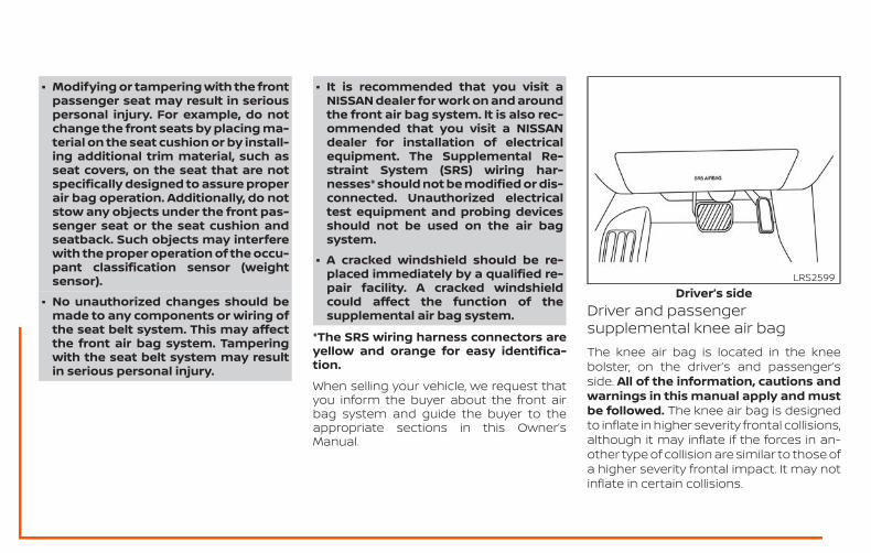
∙ Modifying or tampering with the frontpassenger seat may result in seriouspersonal injury. For example, do notchange the front seats by placing ma-terial on the seat cushion or by install-ing additional trim material, such asseat covers, on the seat that are notspecifically designed to assure properair bag operation. Additionally, do notstow any objects under the front pas-senger seat or the seat cushion andseatback. Such objects may interferewith the proper operation of the occu-pant classification sensor (weightsensor).
∙ No unauthorized changes should bemade to any components or wiring ofthe seat belt system. This may affectthe front air bag system. Tamperingwith the seat belt system may resultin serious personal injury.
∙ It is recommended that you visit aNISSAN dealer for work on and aroundthe front air bag system. It is also rec-ommended that you visit a NISSANdealer for installation of electricalequipment. The Supplemental Re-straint System (SRS) wiring har-nesses* should not be modified or dis-connected. Unauthorized electricaltest equipment and probing devicesshould not be used on the air bagsystem.
∙ A cracked windshield should be re-placed immediately by a qualified re-pair facility. A cracked windshieldcould affect the function of thesupplemental air bag system.
*The SRS wiring harness connectors areyellow and orange for easy identifica-tion.
When selling your vehicle, we request thatyou inform the buyer about the front airbag system and guide the buyer to theappropriate sections in this Owner’sManual.
Driver and passengersupplemental knee air bagThe knee air bag is located in the kneebolster, on the driver’s and passenger’sside. All of the information, cautions andwarnings in this manual apply and mustbe followed. The knee air bag is designedto inflate in higher severity frontal collisions,although it may inflate if the forces in an-other type of collision are similar to those ofa higher severity frontal impact. It may notinflate in certain collisions.
Driver’s sideLRS2599
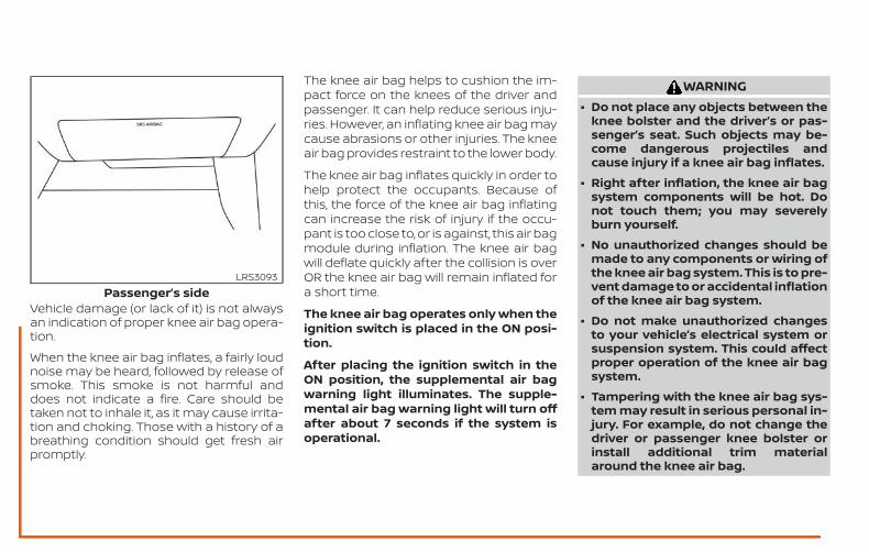
Vehicle damage (or lack of it) is not alwaysan indication of proper knee air bag opera-tion.
When the knee air bag inflates, a fairly loudnoise may be heard, followed by release ofsmoke. This smoke is not harmful anddoes not indicate a fire. Care should betaken not to inhale it, as it may cause irrita-tion and choking. Those with a history of abreathing condition should get fresh airpromptly.
The knee air bag helps to cushion the im-pact force on the knees of the driver andpassenger. It can help reduce serious inju-ries. However, an inflating knee air bag maycause abrasions or other injuries. The kneeair bag provides restraint to the lower body.
The knee air bag inflates quickly in order tohelp protect the occupants. Because ofthis, the force of the knee air bag inflatingcan increase the risk of injury if the occu-pant is too close to, or is against, this air bagmodule during inflation. The knee air bagwill deflate quickly after the collision is overOR the knee air bag will remain inflated fora short time.
The knee air bag operates only when theignition switch is placed in the ON posi-tion.
After placing the ignition switch in theON position, the supplemental air bagwarning light illuminates. The supple-mental air bag warning light will turn offafter about 7 seconds if the system isoperational.
WARNING∙ Do not place any objects between the
knee bolster and the driver’s or pas-senger’s seat. Such objects may be-come dangerous projectiles andcause injury if a knee air bag inflates.
∙ Right after inflation, the knee air bagsystem components will be hot. Donot touch them; you may severelyburn yourself.
∙ No unauthorized changes should bemade to any components or wiring ofthe knee air bag system. This is to pre-vent damage to or accidental inflationof the knee air bag system.
∙ Do not make unauthorized changesto your vehicle’s electrical system orsuspension system. This could affectproper operation of the knee air bagsystem.
∙ Tampering with the knee air bag sys-tem may result in serious personal in-jury. For example, do not change thedriver or passenger knee bolster orinstall additional trim materialaround the knee air bag.
Passenger’s sideLRS3093
∙ It is recommended that you visit aNISSAN dealer for work on and aroundthe knee air bag. It is also recom-mended that you visit a NISSAN dealerfor installation of electrical equip-ment. The SRS wiring harnesses*should not be modified or discon-nected. Unauthorized electrical testequipment and probing devicesshould not be used on the knee airbag system.
*The SRS wiring harness or connectorsare yellow or orange for easy identifica-tion.
When selling your vehicle, we request thatyou inform the buyer about the knee airbag system and guide the buyer to theappropriate sections in this manual.
Seat belt with pretensioner(s)(front and rear outboard seats)
WARNING∙ The pretensioner(s) cannot be reused
after activation. They must be re-placed together with the retractorand buckle as a unit.
∙ If the vehicle becomes involved in acollision but pretensioner(s) are notactivated, be sure to have the preten-sioner system checked and, if neces-sary, replaced. It is recommended thatyou visit a NISSAN dealer for thisservice.
∙ No unauthorized changes should bemade to any components or wiring ofthe pretensioner system. This is toprevent damage to or accidental acti-vation of the pretensioner(s). Tamper-ing with the pretensioner system mayresult in serious personal injury.
∙ It is recommended that you visit aNISSAN dealer for work on and aroundthe pretensioner system. It is also rec-ommended that you visit a NISSANdealer for installation of electricalequipment. Unauthorized electricaltest equipment and probing devicesshould not be used on the preten-sioner system.
∙ If you need to dispose of the preten-sioner(s) or scrap the vehicle, it is rec-ommended that you visit a NISSANdealer for this service. Incorrect dis-posal procedures could cause per-sonal injury.
The pretensioner system may activatewith the supplemental air bag system incertain types of collisions. Working with theseat belt retractor, the pretensioner(s) helptighten the seat belt when the vehicle be-comes involved in certain types of colli-sions, helping to restrain front and rear out-board seat occupants.
The pretensioner(s) are encased within theseat belt retractor and to the seat belt an-chor affixed to the floor of the vehicle.These seat belts are used the same way asconventional seat belts.
When pretensioner(s) activate, smoke is re-leased and a loud noise may be heard. Thissmoke is not harmful and does not indi-cate a fire. Care should be taken not toinhale it, as it may cause irritation andchoking. Those with a history of a breath-ing condition should get fresh air promptly.
After the pretensioner(s’) activation, loadlimiters allow the seat belt to release web-bing (if necessary) to reduce forces againstthe chest.
The supplemental air bag warninglight is used to indicate malfunctionsin the pretensioner system. For additionalinformation, refer to "Supplemental air bagwarning light" in this section. If the opera-
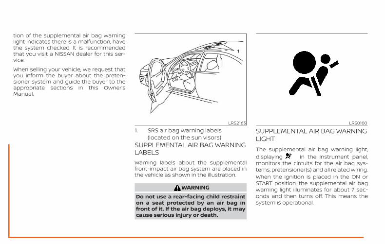
tion of the supplemental air bag warninglight indicates there is a malfunction, havethe system checked. It is recommendedthat you visit a NISSAN dealer for this ser-vice.
When selling your vehicle, we request thatyou inform the buyer about the preten-sioner system and guide the buyer to theappropriate sections in this Owner’sManual.
1. SRS air bag warning labels(located on the sun visors)
SUPPLEMENTAL AIR BAG WARNINGLABELSWarning labels about the supplementalfront-impact air bag system are placed inthe vehicle as shown in the illustration.
WARNINGDo not use a rear-facing child restrainton a seat protected by an air bag infront of it. If the air bag deploys, it maycause serious injury or death.
SUPPLEMENTAL AIR BAG WARNINGLIGHTThe supplemental air bag warning light,displaying in the instrument panel,monitors the circuits for the air bag sys-tems, pretensioner(s) and all related wiring.When the ignition is placed in the ON orSTART position, the supplemental air bagwarning light illuminates for about 7 sec-onds and then turns off. This means thesystem is operational.
LRS2163 LRS0100
If any of the following conditions occur, thefront air bag, side air bag and curtain airbag and pretensioner systems need ser-vicing:
∙ The supplemental air bag warning lightremains on after approximately 7 sec-onds.
∙ The supplemental air bag warning lightflashes intermittently.
∙ The supplemental air bag warning lightdoes not come on at all.
Under these conditions, the front air bag,side air bag and curtain air bag or preten-sioner systems may not operate properly.They must be checked and repaired. It isrecommended that you visit a NISSANdealer for this service.
WARNINGIf the supplemental air bag warninglight is on, it could mean that the frontair bag, side air bag, curtain air bagand/or pretensioner systems will notoperate in an accident. To help avoidinjury to yourself or others, have yourvehicle checked as soon as possible. It isrecommended that you visit a NISSANdealer for this service.
Repair and replacementprocedureThe front air bags, side air bags, curtain airbags and pretensioner(s) are designed toinflate on a one-time-only basis. As a re-minder, unless it is damaged, the supple-mental air bag warning light remains illu-minated after inflation has occurred. Thesesystems should be repaired and/or re-placed as soon as possible. It is recom-mended that you visit a NISSAN dealer forthis service.
When maintenance work is required on thevehicle, the front air bags, side air bags,curtain air bags, pretensioner(s) and re-lated parts should be pointed out to theperson performing the maintenance. Theignition switch should always be placed inthe LOCK position when working under thehood or inside the vehicle.
WARNING∙ Once a front air bag, side air bag, or
curtain air bag has inflated, the airbag module will not function againand must be replaced. Additionally,the activated pretensioner(s) mustalso be replaced. The air bag moduleand pretensioner(s) should be re-placed. It is recommended that youvisit a NISSAN dealer for this service.However, the air bag module and pre-tensioner(s) cannot be repaired.
∙ The front air bag, side air bag, curtainair bag systems and the pretensionersystem should be inspected if there isany damage to the front end or sideportion of the vehicle. It is recom-mended that you visit a NISSAN dealerfor this service.
∙ If you need to dispose of the supple-mental air bag or pretensioner sys-tems or scrap the vehicle, it is recom-mended that you visit a NISSANdealer. Incorrect disposal procedurescould cause personal injury.
∙ If there is an impact to your vehiclefrom any direction, your OccupantClassification Sensor (OCS) should bechecked to verify it is still functioningcorrectly. It is recommended that youvisit a NISSAN dealer for this service.The OCS should be checked even if noair bags deploy as a result of the im-pact. Failure to verify proper OCSfunction may result in an improper airbag deployment resulting in injury ordeath.