Embed Size (px)
Citation preview

Limiter Redesign Process™Bit and BHA Forensics
2021-03-25
Paul PastusekDrilling Mechanics AdvisorUIS - Wells TechnicalExxonMobil Upstream Integrated Solutions
The presentation and audio of this session will be recorded and utilized in future online learning. If you choose to not have your voice recorded, please post any questions or feedback in the Q&A window to be captured and discussed during the session.
Please obtain permission before using any material from this presentation and reference the source.

• Forensics Analysis Learning Objectives• Observations and Documentation• Bit Forensics
• Reading Fracture Initiation and Direction of Loading• Bit Wear Scars – Mechanical and Thermal• Erosion and Corrosion
• BHA Forensics• BHA Wear Scars and Direction of Motion• Torsion and HFTO Loads
• Bit Balling and Ribbon Flow
Outline

Incorporate forensic analysis of bit and BHA wear scars and fractures as a diagnostic tool for identifying key limiters and corrective actions.
Forensic Analysis Learning Objectives

• Foundation for continuous improvement
• Utilize on offsets as well as current well
• Document the bit and the BHA• Photos required• IADC dull grades are insufficient
(that is why we have started to upgrade that system)
Forensic AnalysisDull Grade
1-1-BT-N-X-I-WT-TD

• Bit Photos• Label Blades/Cones 1 to n
• Blade #1 has inner most cutter• Head Shot• 45° Side Shot
• Close up photo per blade• Close up photo per cone
• Gauge Pads, Shank, and API Pin if damaged
• BHA Photos• Label stabilizer blades• Note location of even minor wear patterns• Note direction and depth of wear scars• Document diameter and location of stabilizers
• Close up – fill the screen• In focus / blur free• Utilize light source direction to highlight scars
Observations and Documentation

Observation and Documentation 1 of 9
BHA Documentation from Turekul Zhangbylov Kazakstan 2011

Observation and Documentation 2 of 9
?

Observation and Documentation 3 of 9

Observation and Documentation 4 of 9

Observation and Documentation 5 of 9

Observation and Documentation 6 of 9

Observation and Documentation 7 of 9
Stabilizer blade #3 has incurred some wear. Likely due to forward whirl.BHA Documentation from Turekul Zhangbylov Kazakstan 2011

Observation and Documentation 8 of 9

Observation and Documentation 9 of 9
All sides look fine. In gauge.

• Reading Fracture Initiation and Direction of Loading• Beach marks / spall - cone, nose, shoulder• Plastic hinge• Tangential cutter fracture
• Bit Wear Scars• BHA Wear Scars
• Forward whirl• Reverse whirl• Borehole patterns
Fracture Patterns and Wear Scars

Bit Forensics

20 feet
Understanding Beach Marks

Load is Approximately
Normal to Edge
Beach Marks Due to Edge Load ~Normal to Profile
Video courtesy of Varel International REF: SPE 199598 Rahmani 2020
Axial Load Can be Combined with Thermal Loads
Beach Marks Due to Edge Load ~Normal to Profile

Lateral Vibration / Reverse WhirlMechanical
Shoulder
Damage

Damage During Drillout or Reaming Off Bottom
Gauge trimmer damage -delamination of the diamond tables

Note: gauge trimmer damage - delamination of the diamond tables, from drilling out inside
of casing.
Possible gauge pad rounding due to whirl….hard to
confirm from this angle.

Axial Vibration and Impact
Green cutters surrounding a delaminated cutter, suggests mechanical failure due to overload normal to the profile.

Axial Load Primarily Damages NoseDamage to
nose/inner rows
No uniform wear
on outside
cutters
Right Image Provided by Smith

Torsional Vibration and Stick-slip• This slide is from around 2008
• Cutter spalling in the cone is very rare today even with severe stick slip due to cutter improvements
• I have dropped this slide from ExxonMobil training as cone spalling is no longer a good diagnostic for stick slip

Lateral Vibration / Bit Whirl
Axial Vibration / Bit Bounce
Stick-Slip
• Shoulder – whirl, lateral• Nose – axial, tag bottom• Cone – stick-slip (rare)
Beach Marks Due to Edge Load ~Normal to Profile

Lateral Vibration / Bit Whirl
Axial Vibration / Bit Bounce
• Shoulder – whirl, lateral• Nose – axial, tag bottom
Beach Marks Due to Edge Load ~Normal to Profile

Questions

• What documentation do you need for a case study?• Photos of the bit and all BHA components• BHA Information• Daily Reports• Digitial Surface (1 sample/sec)• Downhole Data (telemetry and memory)• Formation information
• What is the effect of load direction on failure load?• Diamond table is strongest in compression• Failure is more likely if the table is put in tension
Learnings Check

• What indicates the fracture initiation site for beach marks?• Center of the elipse
• What is the general direction of motion for beach marks?• Cutter edge loading• Normal to the profile
• On what area of the bit will I see beech marks for a) whirl, b) stick-slip, c) axial vibration?
shoulder cone nose
Learnings Check

Hands on demonstration
Trial One• Apply 1-2 lbs of compression along the axis• Break chalk in bendingTrial Two• Apply 1-2 lbs of tension• Break chalk in bending
Plastic Hinge
Plastic Hinge in compression
(last material to break)

Load Direction
“Plastic Hinge” – last surface to fail in bending.
Fracture changes direction due to shear failure.
Gauge trimmer damage due to whirl – possibly inside of casing

• When a plastic hinge is present it can be used to indicate the load direction.
• Indicates compression, the last material to break.
Plastic Hinge

Blade Breakage Direction – Where is the Plastic Hinge?

Hands on demonstration
• Trial• Place the cookie on the table• Hold it down in the middle• Apply load to one edge until it
fractures
Oreo Cookie – Cutter Tangential Fracture Toughness
1
23

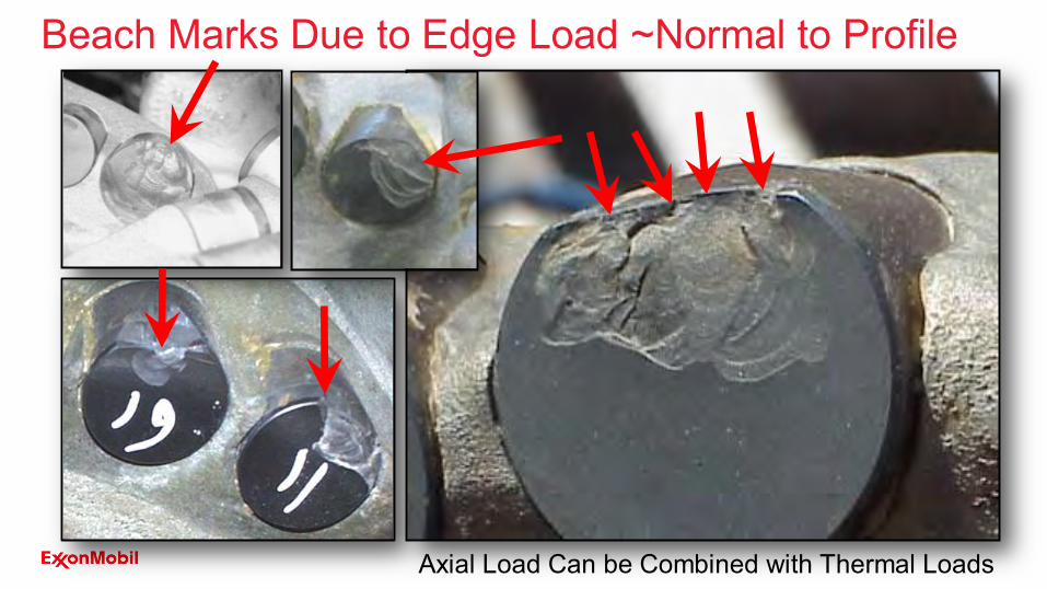
• Over stressed in tangential cutting direction• Fracture is back through diamond and into
carbide substrate• Stiffness Difference - Young’s Modulus
• PDC Diamond 140 x 106 psi• WC Substrate 90 x 106 psi• Steel 30 x 106 psi
Tangential Cutter Fracture
Load Ft Tangential to Edge
Plastic Hinge

Tangential Cutter Fracture

Tangential Cutter Fracture

Structural Limit - Interbedded Formation
Animation courtesy Baker Hughes
Highest load per cutter inside cone until…• Soft to Hard formation transition• Highest load per cutter on the nose

For interbedded formations select cutters for fracture toughness in tangential direction

Structural Limits• Core Out
• Highest load per cutter in the center• Least overlap, yet least wear due to least sliding• In uniform rock – bit will core out due to excess WOB
• Tangential cutter fracture on the nose• Look for interfacial severity• Also look for potential of drill out damage
• What do you do when you reach the Structural Limit?• Redesign the limiter

3 of 5 Short substrate cutters in cone failed

Structural Integrity
7 of 7 small cone cutters failed 8 ½ inch bit at less than 28klb WOB

Core Out – What can we do about it?
Recommended Design Changes1. Put long Substrate cutters in center2. Three-blades-to-center

• Select bits with three blades to center • Avoid short substrate PDC cutters everywhere• Avoid bits with smaller cutters inside the cone• Work with vendors to select cutters based on tangential
fracture toughness (Engage Drilling Technical for help)
• Push for more fracture resistant cutters• Current 8 ½ WOB Limit - 77klb (50klb downhole)
• 3 blades to center, long substrates, 16mm
• Vendor Challenge: Develop models and lab tests to measure and improve structural integrity
Improving Structural Integrity - Recommendations

Load to Failure vs Load Direction
• Concentrated load to edge chamfer only• Compute the stress level in the cutter vs direction• Relate load direction to the load to failure
Ref: SPE 199598-MS

Summary: Tangential Fracture Toughness – Oreo Cookie Break
• Inside Cone – Drill-out damage, Excessive WOB, Stick-Slip
• Trimmers Only - Whirl in casing • On Nose – Hard formation transition, Junk damage• Just Outside Nose – Hard formation transition with
bedding angle• Random - Interfacial Severity
• Chert, Pyrite, Conglomerates, Inclusions, Junk
• First Cutter of Secondary Blades - Substrate erosion

Questions

• What is the general load direction for the Oreo-cookie break?• Tangential – in the cutting direction
• When am I likely to see tangential cutter fracture?• Formations with interfacial severity, junk damage, excess WOB (core out), drill
out damage• On what area of the bit will I see tangential fracture for
a) excess WOB, b) drill out damage, c) interbedded formations? Cone Gauge trimmers Nose
• What design features should be checked if tangential cutter fracture is occurring?• No small cutters, Long substrate cutters, Three blades to center, Cutter
selection
Learnings Check

Hands on demonstration
• Determine• Surfaces in Contact • Direction of Motion• Wear Particle Sizes• Heat Generation vs. Wear
Reading Wear Scars
Fine Grain
Course Grain

With no vibration or overload, cutters will wear smoothlySmooth Wear is function of:• material flow below the cutter (sliding distance)• contact pressure, remember this equals rock strength, it is
independent of depth of cut• abrasiveness (quartz content, size, and shape) – also fixed
Smooth Cutter Wear
Animation courtesy Baker Hughes

Smooth Wear = f (sliding distance, the only thing you can control)Increasing WOB
• increases depth of cut (DOC - in/rev) reduces revolutions required to drill a given distance reduces sliding distance (rev/ft) reduces wear
Example: To drill 100 feet at 120 RPM the outside cutter of an 8-1/2” bit slides:
Smooth Cutter Wear
0.16 inch/rev
0.08 inch/rev
16,000 ft@ 100 fph
32,000 ft @ 50 fph

Smooth Wear = f (sliding distance, the only thing you can control)Increasing WOB
• increases depth of cut (DOC) reduces revolutions required to drill a given distance • reduces sliding distance reduces wear
Example: To drill 100 feet at 120 RPM the outside cutter of an 8-1/2” bit slides:
Smooth Cutter Wear
0.16 inch/rev
0.08 inch/rev
16,000 ft@ 100 fph
32,000 ft @ 50 fph
When do I stop adding WOB?

Without vibration, mechanical or thermal stress overload, cutters will wear smoothlySmooth Wear is function of:• Contact pressure, remember this equals rock
strength, it is independent of depth of cut• Abrasiveness (quartz content, size, and shape)• Material flow below the cutter (sliding distance)• Cutter temperature
Smooth Cutter Wear
Animation courtesy Baker Hughes

Smooth Wear = f (sliding distance, and temperature)Increasing WOB
• increases depth of cut (DOC - in/rev) reduces revolutions required to drill a given distance reduces sliding distance (rev/ft) reduces wear
Example: To drill 100 feet at 120 RPM the outside cutter of an 8-1/2” bit slides:
Smooth Cutter Wear
0.16 inch/rev
0.08 inch/rev
16,000 ft@ 100 fph
32,000 ft @ 50 fph

Smooth Wear = f (sliding distance, and temperature)Cutter temperature is a function of:
• Mud heat capacity, surface film – water is best• Wear flat area – wear can go non-linear• Sliding speed – Radius and RPM• Local mud velocity (CFD, 2nd nozzles)• Rock strength• Abrasiveness (abrasive formations carry heat
away from wear flat, non-abrasive heat cutters)• Depth of cut – temperature increases only
slightly, the ribbon carries away most of the energy & heat
• Cutter thermal stability
Smooth Cutter Wear
Ref: AADE12-FTCE-38 Freeman 2012

Damage vs Temperature
58Graphic courtesy of NOV
Note that damage is a strong function of temperature.
Temperature is affected by RPM and wear flat size.
Below the thermal limit, the wear is linear with sliding distance.

Smooth Wear to Thermal-Mechanical Damage
59Charts courtesy of US Synthetic
The “red” cutter is more thermally stable and therefore has a more linear wear progression than the “blue” cutter. Once the blue cutter starts wearing it heats up and the heat rapidly degrades the cutter.

Spalling Can Be Due to Combined Thermo-Mechanical Effects
60
REF: Classification of Polycrystalline Diamond Compact (PDC) Cutter Damage Witt-Doerring 2021
(a)Micro-spalls along wear flats - thermal; (b) Spalling of thermo-mechanical origin
(a) (b)

• Localized shoulder damage
• Smooth wear should be more uniform
• This suggests fracture, followed by wear, followed by thermal spalls
Mechanical, Then Wear, Then Thermal Damage
61

Heat Checking in Non-abrasive Hard Formations

Smooth Wear = f (sliding distance, and temperature)Increasing WOB
• increases depth of cut (DOC - in/rev) reduces revolutions required to drill a given distance reduces sliding distance (rev/ft) reduces wear
Example: To drill 100 feet at 120 RPM the outside cutter of an 8-1/2” bit slides:
Smooth Cutter Wear
0.16 inch/rev
0.08 inch/rev
16,000 ft@ 100 fph
32,000 ft @ 50 fph
When do I stop adding WOB?
When do I reduce RPM?
Stop adding WOB when cutters fracture in the cutting direction, only until the limiter can be redesigned. Add WOB early, not
after the wear flat forms.
Lower RPM when you see thermal damage, only until the limiter can
be redesigned.

Questions

• We drill into a formation that has 2X compressive strength and we double the WOB, what happens to the ROP? What happens to wear? • ROP is the same. • Wear goes up 2X: same sliding and 2X the strength
• We drill into a formation that has 3X higher compressive strength with the same parameters, what happens to the ROP? What about wear? • ROP drops to one third. Wear goes up 9X
• 3X the sliding distance and 3X the strength• If we drop WOB in half and double the RPM, what will the ROP do?
What will the wear do?• ROP is unchanged. The bit will turn 2X revolutions thus 2X wear…if we don’t
vibrate or thermally overload the cutters.
Learnings Check

Cutter Material Selection and Types• There continue to be major improvements in PDC cutter technology• Work with vendors to pick cutters based on the specific application and damage• Pick a bit service company that has an active well documented lab and field trial
process with low latency• Service companies should provide test data on both tangential and axial fracture
toughness – both are needed• Insure they select cutters based on forensics for: smooth wear resistance tangential fracture toughness axial fracture resistance/toughness thermal stability
Graphics courtesy of US Synthetic
Vendor Design Options• Grain size• Layered material• Treated – leached• Thermal stability• Residual stress• Interface design

Erosion and Wear - markers of time and flow direction

Nozzle Orientation and Erosion
Vel (ft/sec)
Graphics courtesy of Halliburton
BLD 1
BLD 5

Cutter Corrosion
Graphics courtesy of PV Fluids Pitting Corrosion in High Stress Areas
– Diagnostic for other BHA damage

BHA Forensics
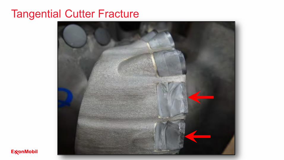
Reverse Bit Whirl
Graphics and Animations used with permission of Baker Hughes
F

Forward Bit Whirl
Video courtesy of Baker Hughes

Forward Bit Whirl – uneven wear per side

• Diagnostics• BHA bending• Eccentric BHA wear scars
Forward BHA Whirl
Photos courtesy of
Baker Hughes
Video courtesy of
Schlumberger

Forward BHA Whirl

Forward BHA Whirl

Forward Whirl – How bad can it get?
Drill Pipe / Tool Joint In Line Stabilizer

Reverse BHA Whirl
Video courtesy of
Schlumberger

Reverse Bit whirl and Reverse BHA whirl
Severe nicks and dents on MWD are due
to embedded broken inserts
Reverse BHA Whirl
Graphics used with permission of Baker Hughes
Mitigation
Increase WOB to suppress bit whirlChange the RPM away from the natural excitation frequency Change the natural frequency away from the required RPM
Change massChange stabilizer spacingImprove damping
Reduce friction forces Improve borehole qualityReplace stabilizers with roller reamersAdd mud lubricantsTrial low friction stabilizers
Reduce WOB if buckling or redesign BHA
79
Bulged pipe from compression fatigue with reverse whirl

Spiral Patterns Induce Stabilizer End Wear
Photos courtesy NOV
Borehole pattern
from Piceance
Creek, CO

Stabilizer End Wear is Diagnostic for PatternsThe formation is abrasive, but this wear is due to the stabilizer drilling on a pattern or multiple ledges.
Sable Island
6 ¾ PD Xceed
Upper Stabilizer
SYU Chert
String Stabilizer
Hibernia

8-1/8” Top Stabilizer 6 ¾ PD Xceed

Graphics courtesy Halliburton Graphics courtesy Halliburton
Spiral Patterns How bad can it get?

Torsional Failure and HFTO Damage – 45 Cracks
84
High Frequency Torsional Oscillation (HFTO) results in X shaped fractures due to stress reversals
Fracture perpendicular to the axis of the tool is due to bending fatigue.Angle of fracture ø = 0This is not due to torsion.
API Pin image courtesy of NOVMWD image courtesy of Baker HughesDC image courtesy of Halliburton
Torsional failure results in 45shear failure

Questions

• If you observe preferential wear on one end of a stabilizer (from the bottom up), what should you suspect? From the top down? How can you be sure?• Borehole patterns. Backreaming with Borehole patterns. • Review ADN and Photo electric Image logs. Look for pattern in near bit
inclination data.• Run a caliper.
• What type of BHA damage should you see with forward whirl?• Smooth wear on one side of the tool. (Jump rope motion)
• You observe rounded gauge pads on a string stabilizer, what do you suspect? • Reverse whirl of the BHA, gearing motion
• When will you likely see heat checking?• High normal load in a formation with low abrasiveness
Learnings Check

• We raise our WOB from 25 to 50 klb and the ROP doubles. What happens to smooth cutter wear?• Sliding distance is cut in half, and wear is cut in half.
• What direction do cracks form for bending fatigue? • Perpendicular to the bending, typically perpendicular to the axis of the tool.
• What directions do cracks form for torsion?• 45 to the axis of torsion
• What cracks can form with high frequency torsional oscillation (HFTO)?• X shaped cracks – forward and reverse torsional loading
Learnings Check

Bit Balling and Ribbon Flow

Bit Balling

Bit Balling
Note cuttings on top of gauge pads. Did this occur on the trip
out or while drilling?
Balling below the pads suggest it occurred while drilling.

Balling – Limestone with 20% clay

Bit Balling – NAF Mud

• Check vendor’s computational fluid dynamics (CFD) results• Review vendor’s cuttings trajectory model (and knowledge)• Increase blade standoff inside cone (2-3 cutter diameters)
• Look for and avoid choke points• Rule of thumb for blade clearance – 3/4 inch width• Deflect cuttings toward the bit OD and junk slots - Avoid convergence
Ribbon Flow Affects Balling
93Pinch Point
SPE 114673
Graphics used with permission Baker Hughes 12 ¼ Hibernia

Balling – Laying Bricks

Where are the ribbons going to flow?First 7 cutters have no clearance.
Ribbon Flow Problems
Cutters are recessed from front of blade, interfere with
ribbon flow.

Ribbon Flow Problems

Ribbon Flow Problems – Body Erosion and Pack Off

Questions

• How much material accumulation is required to call it balling? • Any accumulation of cuttings that affect the bit loads.
• How hard are the ribbons when first formed?• Equal to or above rock strength if fine grained and low permeability• May be zero in high permeability sands
• Can the bit ball up with oil based mud? Can the bit ball in a limestone?Yes No & Yes – make sure it is a limestone and not marl
• How can we detect ribbon flow issues?• Ask vendors to show their ribbon flow model results• Look for insufficient chip flow clearance in front of cutters• Look for particle flow erosion surrounding the cutter
Learnings Check

• Forensics Analysis Learning Objectives• Observations and Documentation• Bit Forensics
• Reading Fracture Initiation and Direction of Loading• Bit Wear Scars – Mechanical and Thermal• Erosion and Corrosion
• BHA Forensics• BHA Wear Scars and Direction of Motion• Torsion and HFTO Loads
• Bit Balling and Ribbon Flow
Summary

• Rahmani, R., Pastusek, P., Yun, G., & Roberts, T. (2020, February 25). Investigation of Geometry and Loading Effects on PDC Cutter Structural Integrity in Hard Rocks. Society of Petroleum Engineers. doi:10.2118/199598-MS
• Dunn, K. J. and Lee, M. (1979). The fracture and fatigue of sintered diamond compact. Journal of Materials Science, 14, 4, 882–890
• Kanyanta, V., Dormer, A., Murphy, N, Ivankovic, A. (2014). Impact fatigue fracture of polycrystalline diamond compact (PDC) cutters and the effect of microstructure. International Journal of Refractory Metals and Hard Materials, 46, 145-151
• Lin, T.-P., Hood, M., Cooper, G.A., and Smith, R.H. (1994). Residual Stresses in Polycrystalline Diamond Compacts. J. Am. Ceram. Soc., 77 (6), 1562-1568
• McNamara D., Alveen P., Carolan D., et al. (2015). Fracture toughness evaluation of polycrystalline diamond as a function of microstructure. Eng Fract Mech., 143, 1–16
• McNamara D., Carolan D., Alveen P., Murphy N., Ivanković A. (2016). Effect of loading rate on the fracture toughness and failure mechanisms of polycrystalline diamond (PCD). Int. Journal of Refractory Metals and Hard Materials, 60, 1–10
• Ersoy A., Waller M.D. (1995, September). Wear characteristics of PDC pin and hybrid core bits in rock drilling. Wear, 188, 1–2, 150-165
• Zhan, G. (David), Patin, A., Pillai, R., Gilleylen, R., & Castagna, M. (2014, March 4). In-Situ Analysis of the Microscopic Thermal Fracture Behavior of PDC Cutters Using Environmental Scanning Electron Microscope. Society of Petroleum Engineers. doi:10.2118/168004-MS
References
101

• Pastusek, P., Sanderson, D., Minkevicius, A., Blakeman, Z., & Bailey, J. (2018, March 6). Drilling Interbedded and Hard Formations with PDC Bits Considering Structural Integrity Limits. Society of Petroleum Engineers. doi:10.2118/189608-MS
• Tze-Pin, Lin, Michael Hood, George A. Cooper, Xiaohong, Li (1992, July 15). Wear and failure mechanisms of polycrystalline diamond compact bits. Wear, 156, 1, 133-150
• Zacny, K. (2012, March 1). Fracture and Fatigue of Polycrystalline-Diamond Compacts. Society of Petroleum Engineers. doi:10.2118/150001-PA
• Moseley, S.G., Bohn, K.P., Goedickemeier, M. (2009). Core Drilling in Reinforced Concrete using Polycrystalline Diamond (PDC) Cutters: Wear and Fracture Mechanisms. Int. Journal of Refractory Metals & Hard Materials, 27, 2, 394‐402
• Zeuch, D. H., & Finger, J. T. (1985, January 1). Rock Breakage Mechanisms With a PDC Cutter. Society of Petroleum Engineers. doi:10.2118/14219-MS
• Defoort, T., Paluszny, A., Zimmerman, R. W., Botton, B., & Ivie, B. (2017, August 28). Numerical Study of the Contact Between a Chamfered Cylindrical PDC Cutter and the Rock. American Rock Mechanics Association.
• Glowka, D.A. 1985. Implications of thermal wear phenomena for PDC bit design and operation. In SPE Annual Technical Conference and Exhibition. Society of Petroleum Engineers. Paper SPE 14222.
• Freeman, M. A., Shen, Y.,Zhang, Y, (April 10-12, 2012) Single PDC Studies of Fluid Transfer and Cutter Mortality in Drilling Fluid, AADE-12-FTCE-38
References
102