Embed Size (px)
Citation preview
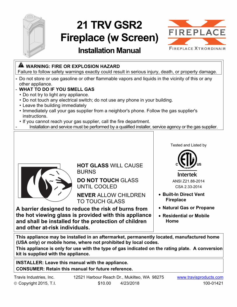
21 TRV GSR2 Fireplace (w Screen)
Installation Manual
WARNING: FIRE OR EXPLOSION HAZARD Failure to follow safety warnings exactly could result in serious injury, death, or property damage.
- Do not store or use gasoline or other flammable vapors and liquids in the vicinity of this or any other appliance.
- WHAT TO DO IF YOU SMELL GAS • Do not try to light any appliance. • Do not touch any electrical switch; do not use any phone in your building. • Leave the building immediately • Immediately call your gas supplier from a neighbor's phone. Follow the gas supplier's
instructions. • If you cannot reach your gas supplier, call the fire department.
- Installation and service must be performed by a qualified installer, service agency or the gas supplier.
HOT GLASS WILL CAUSE BURNS
DO NOT TOUCH GLASS UNTIL COOLED
NEVER ALLOW CHILDREN TO TOUCH GLASS
A barrier designed to reduce the risk of burns from the hot viewing glass is provided with this appliance and shall be installed for the protection of children and other at-risk individuals.
Tested and Listed by
ANSI Z21.88-2014
CSA 2.33-2014
Built-In Direct Vent Fireplace
Natural Gas or Propane
Residential or Mobile Home
This appliance may be installed in an aftermarket, permanently located, manufactured home (USA only) or mobile home, where not prohibited by local codes. This appliance is only for use with the type of gas indicated on the rating plate. A conversion kit is supplied with the appliance.
INSTALLER: Leave this manual with the appliance. CONSUMER: Retain this manual for future reference.
Travis Industries, Inc. 12521 Harbour Reach Dr., Mukilteo, WA 98275 www.travisproducts.com
Copyright 2015, T.I. $10.00 4/23/2018 100-01421

2 Introduction
© Travis Industries 4/12/2018 - 1421 21TRV GSR2
Overview This manual details the installation requirements for the 21 TRV GSR2 fireplace. For operating and maintenance instructions, refer to the 21 TRV GSR2 Owner's Manual (part # 100-01422).
Listing Details This appliance was listed by Intertek Test Labs to ANSI Z21.88. The listing label is attached to the appliance near the gas control valve. A copy is shown to the right.
Massachusetts Approval
This manual has been submitted to the Massachusetts Board of State Examiners of Plumbers and Gas Fitters.
National Fireplace Institute
Repo
rt No
. 101
4232
90PR
T-00
1Co
ntro
l No.
4000
515
Vent
ed G
as F
irepl
ace
Hea
ter
21 T
RV
GSR
2
Test
ed to
: ANS
I Z21
.88-2
014/C
SA 2.
33-2
014 “
Vent
ed G
as F
irepl
ace H
eate
r”, C
GA 2.
17-M
91 (R
2009
) “Ga
s Bur
ning
He
atin
g App
lianc
es fo
r Man
ufac
ture
d Ho
mes
”, an
d CS
A P.4
.1-09
Test
ing
met
hod
for m
easu
ring
annu
al fir
eplac
e ef
ficien
cy.
This
appl
iance
mus
t be
inst
alled
in a
ccor
danc
e wi
th lo
cal c
odes
, if a
ny; i
f non
e, fo
llow
the
Natio
nal F
uel G
as
Code
, ANS
I Z22
3.1/N
FPA
54, o
r Nat
ural
Gas a
nd P
ropa
ne In
stall
atio
n Co
des,
CSA
B149
.1.Th
is ap
plian
ce m
ust b
e in
stall
ed in
acc
orda
nce
with
the
curre
nt S
tand
ard
CAN/
CSA
Z240
MH,
Mob
ile H
ousin
g,
in C
anad
a or
with
the
Manu
fact
ured
Hom
e Co
nstru
ctio
ns a
nd S
afet
y St
anda
rd, T
itle
24 C
FR, P
art 3
280,
in th
e Un
ited S
tate
s, or
whe
n suc
h a st
anda
rd is
not a
pplic
able,
ANS
I/NCS
BCS
A225
.1/NF
PA 50
1A, M
anuf
actu
red H
ome
Inst
allat
ion
Stan
dard
.Th
is ve
nted
gas f
irepl
ace h
eate
r is e
quip
ped a
t the
fact
ory f
or us
e with
natu
ral g
as. If
conv
ersio
n to p
ropa
ne (L
P)
is de
sired
, the
opt
iona
l fac
tory
conv
ersio
n kit
mus
t be u
sed.
Par
t No.
250-
0237
6 (SI
T) o
r 225
-202
31 &
225-
2017
3 (P
SE)r
egist
er ki
t may
be u
sed.
This
appl
iance
is o
nly
for u
se w
ith th
e ty
pe o
f gas
indi
cate
d on
the
ratin
g pl
ate
and
may
be
inst
alled
in a
n af
term
arke
t, per
man
ently
loca
ted,
man
ufac
ture
d hom
e (US
A on
ly) or
mob
ile ho
me,
wher
e not
proh
ibite
d by l
ocal
code
s. Se
e ow
ner’s
man
ual f
or d
etail
s. T
his
appl
iance
is n
ot c
onve
rtibl
e fo
r use
with
oth
er g
ases
, unl
ess
a ce
rtifie
d kit
is u
sed.
This
vent
ed g
as fi
repl
ace h
eate
r is n
ot fo
r use
with
air f
ilter
s.Ke
ep b
urne
r an
d co
ntro
l co
mpa
rtmen
t cle
an.
See
inst
allat
ion
and
oper
atin
g in
stru
ctio
ns a
ccom
pany
ing
appl
iance
.Th
is ap
plian
ce m
ust
be p
rope
rly c
onne
cted
to
a ve
ntin
g sy
stem
in a
ccor
danc
e wi
th t
he m
anuf
actu
rer’s
in
stall
atio
n in
stru
ctio
ns. U
se o
nly a
ppro
ved
coax
ial d
irect
vent
syst
em to
vent
this
appl
iance
to th
e ext
erio
r. Se
e ow
ner’s
man
ual f
or ap
prov
ed b
rand
s of v
entin
g.If
the
vent
-air
inta
ke s
yste
m is
disc
onne
cted
for s
ervic
ing
or a
ny o
ther
reas
on, i
t mus
t be
rese
aled
and
/ or
rein
stall
ed.
WAR
NING
: Im
prop
er in
stall
atio
n, a
djus
tmen
t, alt
erat
ion,
ser
vice
or m
ainte
nanc
e ca
n ca
use
inju
ry o
r pro
perty
da
mag
e. Re
fer t
o th
e ow
ner’s
info
rmat
ion
man
ual p
rovid
ed w
ith th
is ap
plian
ce. F
or a
ssist
ance
or a
dditi
onal
info
rmat
ion
cons
ult a
qua
lified
inst
aller
, ser
vice a
genc
y or t
he g
as su
pplie
r.
VEN
TED
GA
S FI
REP
LAC
E H
EATE
R -
NO
T FO
R U
SE W
ITH
SO
LID
FU
EL
Mini
mum
Clea
ranc
es to
Com
bust
ibles
Fire
plac
e to
Adjac
ent W
allW
ood
Floo
r Ben
eath
Fire
plac
eBa
ck an
d An
gled
Sid
es to
Enc
losu
re
1” (2
6mm
)0”
(0m
m)
0.5” (
13m
m)
Top
and
Side
s to
Enclo
sure
Base
of F
irepl
ace t
o a M
ante
l0”
(0m
m)
See O
wner
’s Ma
nual
FAN
TYPE
VEN
TED
CIRC
ULAT
ORBl
ower
Elec
trica
l Rat
ing:
115V
., 1.5
Amps
, 60 H
zPa
rt No
. 990
0016
3 fan
or b
lowe
r ass
embl
y may
be u
sed
Mini
mum
Inlet
Pre
ssur
e (in
ches
W.C
.)Ma
ximum
Inlet
Pre
ssur
e (in
ches
W.C
.)Ma
nifo
ld P
ress
ure o
n “H
I” (in
ches
W.C
.)
L.P. 11”
13”
10”
N.G.
5.5”
7” 3.5”
Inpu
t Rat
e on
“HI”
(BTU
/Hr)
Inpu
t Rat
e on
“LO”
(BTU
/Hr)
Orifi
ce S
ize -
Fron
t (DM
S)Or
ifice
Size
- Re
ar (D
MS)
L.P.
16,50
05,0
00#6
7#6
6
N.G.
16,50
06,0
00#5
5#5
5
This
appl
iance
is eq
uipp
ed fo
r use
onl
y at a
ltitu
des 0
-2,00
0 fee
t (0-
610m
) in
the U
SA. In
Can
ada,
0-4,5
00 fe
et (0
-137
0m).
For a
ltitu
des a
bove
2,00
0 fee
t, th
e ven
t con
figur
atio
n, o
rifice
, or c
ombi
natio
n of
bot
h m
ay n
eed
to b
e cha
nged
.Se
e own
er’s
man
ual f
or in
form
atio
n on
mak
ing
thes
e cha
nges
.
2015
2016
2014
Feb.
Mar
.
Jan.
May
Jun.
Apr
.A
ug.
Sep.
Jul.
Nov
.D
ec.
Oct
.
MA
NU
FAC
TUR
E D
ATE:
WAR
NING
: Fail
ure
to in
stall
this
appl
iance
per
the
man
ufac
ture
r’s in
stru
ctio
ns o
r fail
ure
to u
se o
nly
parts
sp
ecifi
cally
appr
oved
with
this
appl
iance
may
resu
lt in
pro
perty
dam
age o
r per
sona
l inju
ry.
1252
1 H
arbo
ur R
each
Driv
eM
ukilt
eo, W
A 98
275
Manu
fact
ured
by:
www.
travis
prod
ucts
.com
CAUT
ION:
Do n
ot o
pera
te th
is ap
plian
ce w
ith g
lass
rem
oved
, cra
cked
or b
roke
n. R
eplac
emen
t of t
he p
anel(
s) s
houl
d be
don
e by
a lic
ense
d or
qua
lified
serv
ice p
erso
n.09
29
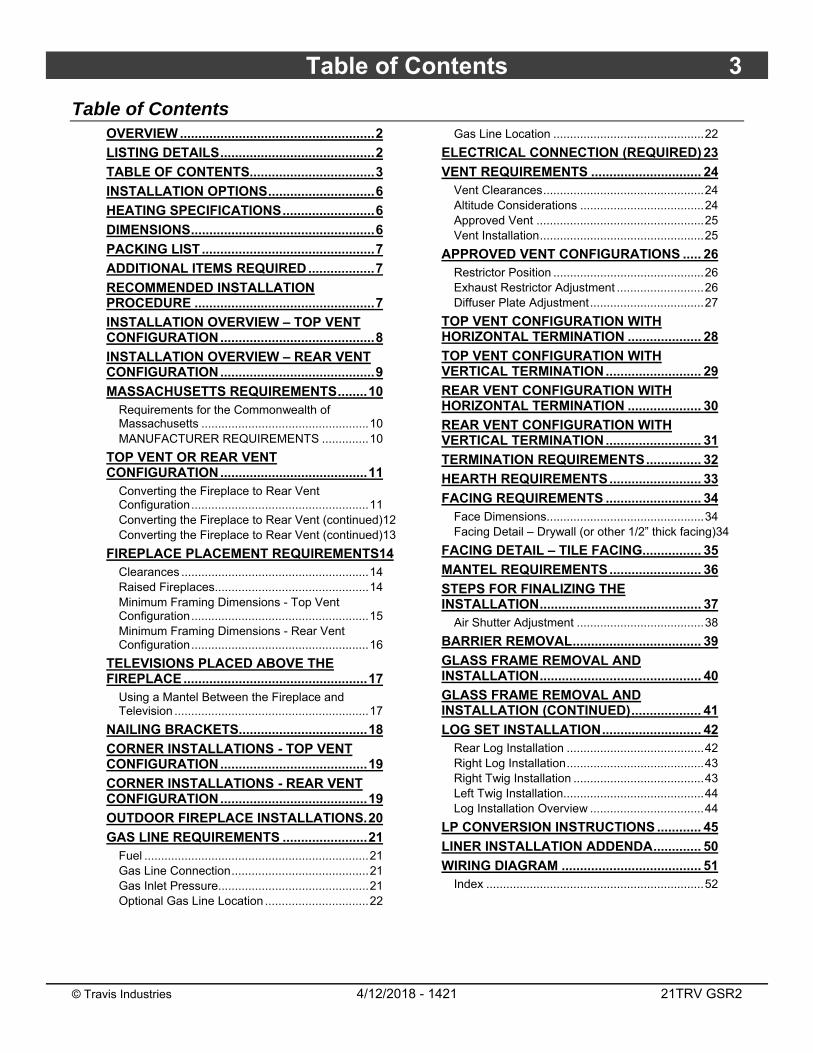
Table of Contents 3
© Travis Industries 4/12/2018 - 1421 21TRV GSR2
Table of Contents OVERVIEW ..................................................... 2
LISTING DETAILS .......................................... 2
TABLE OF CONTENTS.................................. 3
INSTALLATION OPTIONS ............................. 6
HEATING SPECIFICATIONS ......................... 6
DIMENSIONS .................................................. 6
PACKING LIST ............................................... 7
ADDITIONAL ITEMS REQUIRED .................. 7
RECOMMENDED INSTALLATION PROCEDURE ................................................. 7
INSTALLATION OVERVIEW – TOP VENT CONFIGURATION .......................................... 8
INSTALLATION OVERVIEW – REAR VENT CONFIGURATION .......................................... 9
MASSACHUSETTS REQUIREMENTS ........ 10 Requirements for the Commonwealth of Massachusetts .................................................. 10 MANUFACTURER REQUIREMENTS .............. 10
TOP VENT OR REAR VENT CONFIGURATION ........................................ 11
Converting the Fireplace to Rear Vent Configuration ..................................................... 11 Converting the Fireplace to Rear Vent (continued)12 Converting the Fireplace to Rear Vent (continued)13
FIREPLACE PLACEMENT REQUIREMENTS14 Clearances ........................................................ 14 Raised Fireplaces.............................................. 14 Minimum Framing Dimensions - Top Vent Configuration ..................................................... 15 Minimum Framing Dimensions - Rear Vent Configuration ..................................................... 16
TELEVISIONS PLACED ABOVE THE FIREPLACE .................................................. 17
Using a Mantel Between the Fireplace and Television .......................................................... 17
NAILING BRACKETS ................................... 18
CORNER INSTALLATIONS - TOP VENT CONFIGURATION ........................................ 19
CORNER INSTALLATIONS - REAR VENT CONFIGURATION ........................................ 19
OUTDOOR FIREPLACE INSTALLATIONS. 20
GAS LINE REQUIREMENTS ....................... 21 Fuel ................................................................... 21 Gas Line Connection ......................................... 21 Gas Inlet Pressure............................................. 21 Optional Gas Line Location ............................... 22
Gas Line Location ............................................. 22
ELECTRICAL CONNECTION (REQUIRED) 23
VENT REQUIREMENTS .............................. 24 Vent Clearances ................................................ 24 Altitude Considerations ..................................... 24 Approved Vent .................................................. 25 Vent Installation ................................................. 25
APPROVED VENT CONFIGURATIONS ..... 26 Restrictor Position ............................................. 26 Exhaust Restrictor Adjustment .......................... 26 Diffuser Plate Adjustment .................................. 27
TOP VENT CONFIGURATION WITH HORIZONTAL TERMINATION .................... 28
TOP VENT CONFIGURATION WITH VERTICAL TERMINATION .......................... 29
REAR VENT CONFIGURATION WITH HORIZONTAL TERMINATION .................... 30
REAR VENT CONFIGURATION WITH VERTICAL TERMINATION .......................... 31
TERMINATION REQUIREMENTS ............... 32
HEARTH REQUIREMENTS ......................... 33
FACING REQUIREMENTS .......................... 34 Face Dimensions............................................... 34 Facing Detail – Drywall (or other 1/2” thick facing)34
FACING DETAIL – TILE FACING................ 35
MANTEL REQUIREMENTS ......................... 36
STEPS FOR FINALIZING THE INSTALLATION ............................................ 37
Air Shutter Adjustment ...................................... 38
BARRIER REMOVAL ................................... 39
GLASS FRAME REMOVAL AND INSTALLATION ............................................ 40
GLASS FRAME REMOVAL AND INSTALLATION (CONTINUED) ................... 41
LOG SET INSTALLATION ........................... 42 Rear Log Installation ......................................... 42 Right Log Installation ......................................... 43 Right Twig Installation ....................................... 43 Left Twig Installation.......................................... 44 Log Installation Overview .................................. 44
LP CONVERSION INSTRUCTIONS ............ 45
LINER INSTALLATION ADDENDA ............. 50
WIRING DIAGRAM ...................................... 51 Index ................................................................. 52

4 Safety Precautions
© Travis Industries 4/12/2018 - 1421 21TRV GSR2
Safety Warnings
Failure to follow all of the requirements may result in property damage, bodily injury, or even death.
Young children should be carefully supervised when they are in the same room as the appliance. Toddlers, young children and others may be susceptible to accidental contact burns. A physical barrier is recommended if there are at risk individuals in the house. To restrict access to a fireplace or stove, install an adjustable safety gate to keep toddlers, young children and other at risk individuals out of the room and away from hot surfaces.
Children and adults should be alerted to the hazards of high surface temperature and should stay away to avoid burns or clothing ignition. Do not touch the hot surfaces of the heater. Educate all children of the danger of a high-temperature heater.
Due to the high temperature, the heater should be located out of traffic and away from furniture and draperies.
This unit must be installed by a qualified installer to prevent the possibility of an explosion.
This appliance must be installed in accordance with all local codes, if any; if not, in U.S.A. follow ANSI Z223.1 and NFPA 54(88), in Canada follow CSA B149.1. In Australia follow AS/NZS 5601.1.
A manufactured home (USA only) or mobile home OEM installation must conform with the Manufactured Home Construction and Safety Standard, Title 24 CFR, Part 3280, or, when such a standard is not applicable, the Standard for Manufactured Home Installations, ANSI/NCSBCS A225.1, or Standard for Gas Equipped Recreational Vehicles and Mobile Housing, CSA Z240.4. This appliance may be installed in Manufactured Housing only after the home is site located.
All exhaust gases must be vented outside the structure of the living-area. Combustion air is drawn from outside the living-area structure. The venting must not be connected to a chimney flue serving a separate solid-fuel burning appliance.
Notify your insurance company before hooking up this fireplace.
The instructions in this manual must be strictly adhered to. Do not use makeshift methods or compromise in the installation. Improper installation will void the warranty and safety listing.
This heater is approved for use with natural gas (NG) or propane (LP). Burning the incorrect fuel will void the warranty and safety listing and may cause an extreme safety hazard. Direct questions about the type of fuel used to your dealer.
Contact your local building officials to obtain a permit and information on any installation restrictions or inspection requirements in your area.
If the flame becomes sooty, dark orange in color, or extremely tall, do not operate the heater. Call your dealer and arrange for proper servicing.
It is imperative that control compartments, screens, or circulating air passageways of the heater be kept clean and free of obstructions. These areas provide the air necessary for safe operation.
Do not operate the heater if it is not operating properly in any fashion or if you are uncertain. Call your dealer for a full explanation of your heater and what to expect.
Do not store or use gasoline or other flammable liquids in the vicinity of this heater.
Do not operate if any portion of the heater was submerged in water or if any corrosion occurs. Immediately call a qualified service technician to inspect the appliance and to replace any part of the control system and any gas control which has been under water.
Safety Precautions 5
© Travis Industries 4/12/2018 - 1421 21TRV GSR2
Safety Warnings (continued)
Because this heater can be controlled by a thermostat there is a possibility of the heater turning on and igniting any items placed on or near the appliance.
Light the heater using the built-in igniter. Do not use matches or any other external device to light your heater.
Never remove, replace, modify or substitute any part of the heater unless instructions are given in this manual. All other work must be done by a trained technician. Don't modify or replace orifices.
The viewing glass should be opened only for conducting service.
Allow the heater to cool before carrying out any maintenance or cleaning.
Operate the heater according to the instructions included in this manual.
If the main burners do not start correctly turn the gas off and call your dealer for service.
This unit is not for use with solid fuel.
Do not place anything inside the firebox (except the optional artwork).
Warning: Do not operate appliance with the glass front removed, cracked or broken. Replacement of the glass should be done by a licensed or qualified service person.
Do not throw this manual away. This manual has important operating and maintenance instructions that you will need at a later time. Always follow the instructions in this manual.
Instruct everyone in the house how to shut gas off to the appliance and at the gas main shutoff valve. The gas main shutoff valve is usually next to the gas meter or propane tank and requires a wrench to shut off.
A barrier designed to reduce the risk of burns from the hot viewing glass is provided with this appliance and shall be installed for the protection of children and other at-risk individuals.
If the barrier becomes damaged, the barrier shall be replaced with the manufacturer’s barrier for this appliance.
Clothing or other flammable material should not be placed on or near the appliance.
Any safety screen, guard, or barrier removed for servicing an appliance must be replaced prior to operating the appliance.
Installation and repair should be done by a qualified service person. The appliance should be inspected before use and at least annually by a professional service person. More frequent cleaning might be required due to excessive lint from carpeting, bedding material, et cetera. It is imperative that control compartments, burners, and circulating air passageways of the appliance be kept clean.
Travis Industries, Inc. grants no warranty, implied or stated, for the installation or maintenance of your heater, and assumes no responsibility of any consequential damage(s).
Proposition 65 Warning: Fuels used in gas, woodburning or oil fired appliances, and the products of combustion of such fuels, contain chemicals known to the State of California to cause cancer, birth defects and other reproductive harm.
California Health & Safety Code Sec. 25249.6
6 Features and Specifications
© Travis Industries 4/12/2018 - 1421 21TRV GSR2
Installation Options
Residential or Mobile Home
Straight or Corner Placement
Flush or Recessed Face
Raised or Floor Placement
Internal or External Chase
Horizontal or Vertical Vent
Bedroom Approved
Heating Specifications
Natural Gas Propane
Approximate Heating Capacity (in square feet)* Up to 650 Up to 650
Maximum BTU Input Per Hour 16,500 16,500
* Heating capacity will vary with floor plan, insulation, and outside temperature.
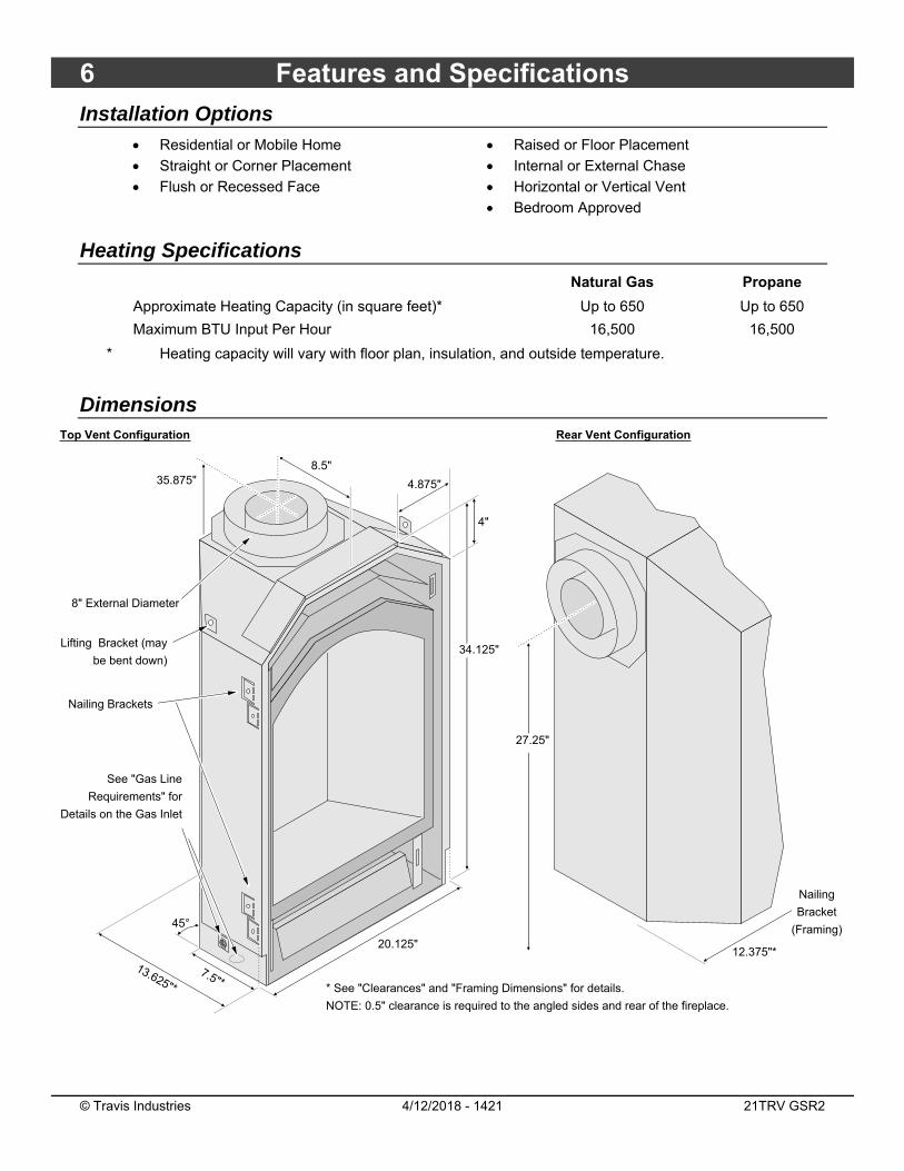
Dimensions
35.875"
8" External Diameter
13.625"*
45°
20.125"
See "Gas Line
Requirements" for
Details on the Gas Inlet
7.5"*
4.875"
Nailing Brackets
4"
Nailing
Bracket
(Framing)
27.25"
Rear Vent Configuration
8.5"
12.375"*
Top Vent Configuration
Lifting Bracket (may
be bent down)34.125"
* See "Clearances" and "Framing Dimensions" for details.
NOTE: 0.5" clearance is required to the angled sides and rear of the fireplace.
Installation (for qualified installers only) 7
© Travis Industries 4/12/2018 - 1421 21TRV GSR2
Packing List Propane Conversion Kit (Orifices, Rivet) Log Set Firestop (sku 93006094)
Rear Vent Configuration Kit (insulation) (4) AA Batteries, (1) 9-Volt Battery Remote Control Felt Tabs (for concealment cover)
Additional Items Required If using LP (propane) a conversion kit is required (sku 94400999 – GSR Stepper Motor Kit).
Direct Vent Gas Line Equipment (shutoff valve, pipe, etc.) Electrical Equipment (min. 14 gauge, grounded line)
Recommended Installation Procedure
HINT: We strongly recommend installing all of the optional equipment before placing the fireplace. Place the fireplace on a suitable work stand to ease installation.
Install the optional equipment (do not install the logs) – we recommend the following order:
a) LP Conversion (if applicable) – NOTE: leave the burner removed until after the liner is installed (if applicable). If using the GreenSmart remote, install the modulating regulator during LP conversion.
b) Liner (if applicable) – NOTE: You will need to loosen the accent light bracket while installing the liner (see page 50).
c) Blower NOTE: Do not install the rheostat if using the GreenSmart remote.
e) Remote
Frame the opening for the fireplace. Make sure to allow for vent installation.
This fireplace is designed to accommodate 1/2" drywall or 1/2” drywall with 3/8” tile (see "Nailing Brackets" on page 17 for details). Secure the fireplace to the framing. NOTE: If the facing is not 1/2" or 7/8" thick, follow the directions below: Place a strip of facing material to both sides of the fireplace opening (NOTE: the strips will be removed after the fireplace is secured). The facing thickness must represent the total thickness of the finished facing (e.g.: If tile is to be used, include the thickness of the backboard, tile, and tile adhesive). Insert the fireplace into the framing. Slide it back until the front edge of the fireplace is flush with the facing material. Secure the fireplace using the plates located along the base of the fireplace.
Complete the gas line installation. Complete the electrical hook-up.
Complete the vent installation.
Install the hearth (if applicable).
Install the drywall and facing (if applicable).
Install the mantel (if applicable).
Finalize the installation (see page 37) and install the grill or face.
8 Installation (for qualified installers only)
© Travis Industries 4/12/2018 - 1421 21TRV GSR2
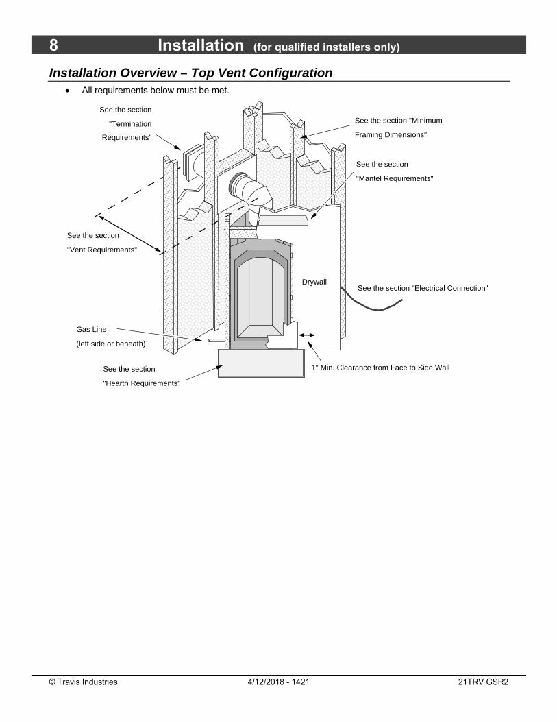
Installation Overview – Top Vent Configuration All requirements below must be met.
See the section
"Termination
Requirements"
�����������
�����������
����������������������
����������������������
����������������������
����������������������
������������������������
������������������������
����������������������
����������������������
���������
������
������������������������
����������������������
����������������������
����������������������
������������������������
������������������������
���������������
��������
Drywall
Gas Line
(left side or beneath)
See the section
"Mantel Requirements"
See the section
"Vent Requirements"
See the section "Minimum
Framing Dimensions"
See the section
"Hearth Requirements"
See the section "Electrical Connection"
1" Min. Clearance from Face to Side Wall
Installation (for qualified installers only) 9
© Travis Industries 4/12/2018 - 1421 21TRV GSR2
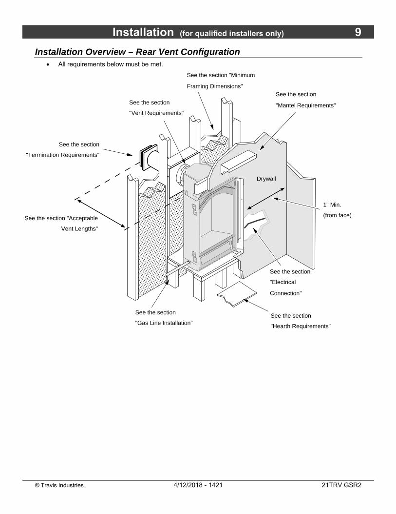
Installation Overview – Rear Vent Configuration All requirements below must be met.
������������������������
������������������������
������������������������
See the section "Acceptable
Vent Lengths"
See the section
"Gas Line Installation"
See the section
"Electrical
Connection"
See the section
"Mantel Requirements"
1" Min.
(from face)
See the section
"Vent Requirements"
See the section "Minimum
Framing Dimensions"
See the section
"Hearth Requirements"
Drywall
See the section
"Termination Requirements"
10 Installation (for qualified installers only)
© Travis Industries 4/12/2018 - 1421 21TRV GSR2
Massachusetts Requirements NOTE: The following requirements reference various Massachusetts and national codes not contained in this document.
Requirements for the Commonwealth of Massachusetts
For all side wall horizontally vented gas fueled equipment installed in every dwelling, building or structure used in whole or in part for residential purposes, including those owned or operated by the Commonwealth and where the side wall exhaust vent termination is less than seven (7) feet above finished grade in the area of the venting, including but not limited to decks and porches, the following requirements shall be satisfied:
Installation of Carbon Monoxide Detectors At the time of installation of the side wall horizontal vented gas fueled equipment, the installing plumber or gasfitter shall observe that a hard wired carbon monoxide detector with an alarm and battery back-up is installed on the floor level where the gas equipment is to be installed. In addition, the installing plumber or gasfitter shall observe that a battery operated or hard wired carbon monoxide detector with an alarm is installed on each additional level of the dwelling, building or structure served by the side wall horizontal vented gas fueled equipment. It shall be the responsibility of the property owner to secure the services of qualified licensed professionals for the installation of hard wired carbon monoxide detectors. In the event that the side wall horizontally vented gas fueled equipment is installed in a crawl space or an attic, the hard wired carbon monoxide detector with alarm and battery back-up may be installed on the next adjacent floor level. In the event that the requirements of this subdivision can not be met at the time of completion of installation, the owner shall have a period of thirty (30) days to comply with the above requirements; provided, however, that during said thirty (30) day period, a battery operated carbon monoxide detector with an alarm shall be installed.
Approved Carbon Monoxide Detectors Each carbon monoxide detector as required in accordance with the above provisions shall comply with NFPA 720 and be ANSI/UL 2034 listed and IAS certified.
Signage A metal or plastic identification plate shall be permanently mounted to the exterior of the building at a minimum height of eight (8) feet above grade directly in line with the exhaust vent terminal for the horizontally vented gas fueled heating appliance or equipment. The sign shall read, in print size no less than one-half (1/2) inch in size, “GAS VENT DIRECTLY BELOW. KEEP CLEAR OF ALL OBSTRUCTIONS”.
Inspection The state or local gas inspector of the side wall horizontally vented gas fueled equipment shall not approve the installation unless, upon inspection, the inspector observes carbon monoxide detectors and signage installed in accordance with the provisions of 248 CMR 5.08(2)(a)1 through 4.
Exemptions The following equipment is exempt from 248 CMR 5.08(2)(a)1 through 4: • The equipment listed in Chapter 10 entitled “Equipment Not Required To Be Vented” in the most current edition of NFPA 54 as adopted by the Board; and • Product Approved side wall horizontally vented gas fueled equipment installed in a room or structure separate from the dwelling, building or structure used in whole or in part for residential purposes.
MANUFACTURER REQUIREMENTS Gas Equipment Venting System Provided
When the manufacturer of Product Approved side wall horizontally vented gas equipment provides a venting system design or venting system components with the equipment, the instructions provided by the manufacturer for installation of the equipment and the venting system shall include: • Detailed instructions for the installation of the venting system design or the venting system components; and • A complete parts list for the venting system design or venting system.
Gas Equipment Venting System NOT Provided When the manufacturer of a Product Approved side wall horizontally vented gas fueled equipment does not provide the parts for venting the flue gases, but identifies “special venting systems”, the following requirements shall be satisfied by the manufacturer: • The referenced “special venting system” instructions shall be included with the appliance or equipment installation instructions; and • The “special venting systems” shall be Product Approved by the Board, and the instructions for that system shall include a parts list and detailed installation instructions. A copy of all installation instructions for all Product Approved side wall horizontally vented gas fueled equipment, all venting instructions, all parts lists for venting instructions, and/or all venting design instructions shall remain with the appliance or equipment at the completion of the installation. See Gas Connection section for additional Commonwealth of Massachusetts requirements.
Installation (for qualified installers only) 11
© Travis Industries 4/12/2018 - 1421 21TRV GSR2
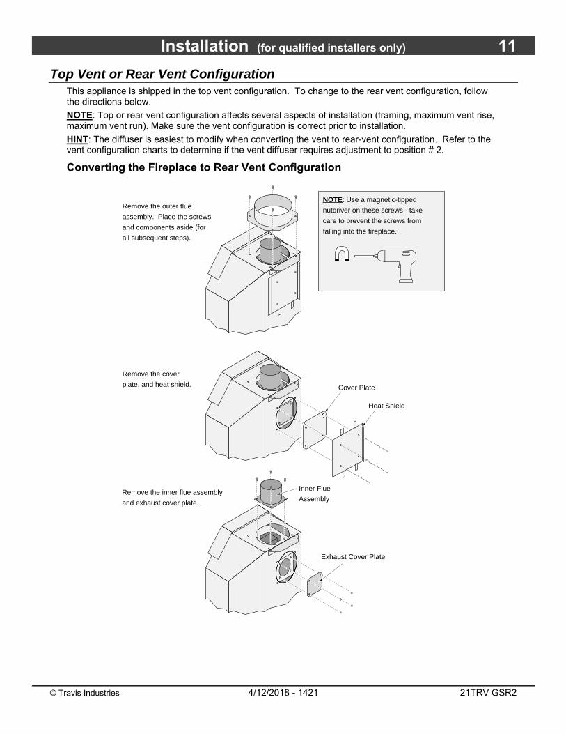
Top Vent or Rear Vent Configuration This appliance is shipped in the top vent configuration. To change to the rear vent configuration, follow the directions below.
NOTE: Top or rear vent configuration affects several aspects of installation (framing, maximum vent rise, maximum vent run). Make sure the vent configuration is correct prior to installation.
HINT: The diffuser is easiest to modify when converting the vent to rear-vent configuration. Refer to the vent configuration charts to determine if the vent diffuser requires adjustment to position # 2.
Converting the Fireplace to Rear Vent Configuration
Remove the cover
plate, and heat shield.
Remove the outer flue
assembly. Place the screws
and components aside (for
all subsequent steps).
NOTE: Use a magnetic-tipped
nutdriver on these screws - take
care to prevent the screws from
falling into the fireplace.
Remove the inner flue assembly
and exhaust cover plate.
Cover Plate
Heat Shield
Exhaust Cover Plate
Inner Flue
Assembly

12 Installation (for qualified installers only)
© Travis Industries 4/12/2018 - 1421 21TRV GSR2
Converting the Fireplace to Rear Vent (continued)
Insert the large piece of insulation into
the intake duct. Note how the wider
portion goes to the sides. Tuck it into
the cavity so it lays flat.
Remove the flue collar suport, rotate it 180°, and re-attach it to the fireplace.
Insert the small piece of insulation into the exhaust
duct. Tuck it into the cavity so it lays flat.
���������������
������������
Attach the exhaust cover
plate, making sure the
attached gasket seals the
exhaust duct.
���������
������
���������������
��������������������
������������
���������������

Installation (for qualified installers only) 13
© Travis Industries 4/12/2018 - 1421 21TRV GSR2
Converting the Fireplace to Rear Vent (continued)
������������
Attach the cover plate to
the top of the fireplace.
NOTE: You will need to
tuck the front edge of the
cover plate under the upper
standoff.
Bend the heat
shield as shown
to the right.
Remove the 4 screws on the angled
top of the fireplace and attach the heat
shield with these screws.
������������
������������
Attach the inner flue
assembly with four
screws (make sure
the gasket is in place
while attaching).
NOTE: Install the flue
assembly with the diffuser
to the bottom.
Attach the outer
flue assembly
with four screws
(make sure the
gasket is in place
while attaching).������������
������������ Bend the exhaust restrictor following
the steps shown below.

14 Installation (for qualified installers only)
© Travis Industries 4/12/2018 - 1421 21TRV GSR2
Fireplace Placement Requirements The fireplace requires a 1/2" clearance from the angled sides and back of the fireplace to the framing
members. No material (insulation, framing, etc.) may be placed into this area.
Fireplace must be installed on a level surface capable of supporting the fireplace and vent.
Fireplace must be placed directly on wood or non-combustible surface (not on linoleum or carpet).
This heater may be placed in a bedroom.
Clearances
When installed, walls in front of the fireplace must be a minimum 1" to the side of the fireplace.
Due to the high temperature, the heater should be located out of traffic and away from furniture and draperies.
Fireplace must be placed so the vents below and above the glass do not become blocked.
Raised Fireplaces
The fireplace (and hearth, if desired) may be placed on a platform designed to support the fireplace (95 Lbs.) and vent.
Make Sure the Fireplace is Raised a Minimum 3/8” (9mm)
! Faces, when installed, extend 3/8” (9mm) below the base of the fireplace. Make sure the fireplace is raised appropriately to allow for face installation.
Raised Platform
Optional Hearth
Minimum
57"
Ceiling
Installation (for qualified installers only) 15
© Travis Industries 4/12/2018 - 1421 21TRV GSR2
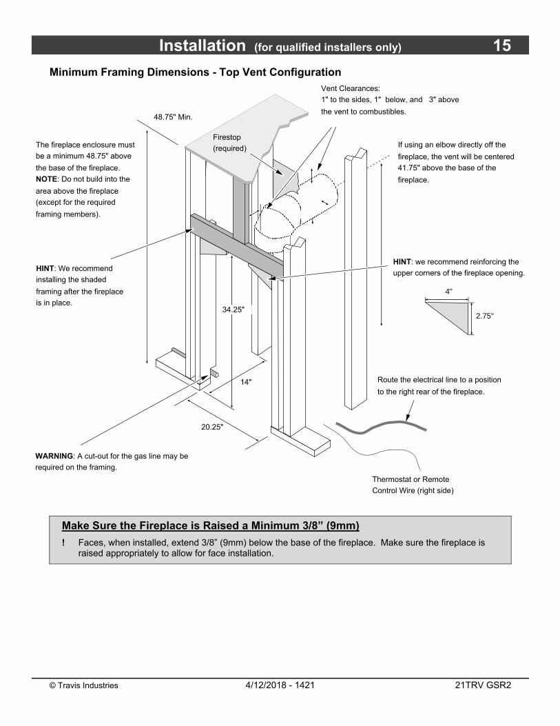
Minimum Framing Dimensions - Top Vent Configuration
Make Sure the Fireplace is Raised a Minimum 3/8” (9mm)
! Faces, when installed, extend 3/8” (9mm) below the base of the fireplace. Make sure the fireplace is raised appropriately to allow for face installation.
���������
��������
��������
�������������
��
��������
����������������
Route the electrical line to a position
to the right rear of the fireplace.
Thermostat or Remote
Control Wire (right side)
If using an elbow directly off the
fireplace, the vent will be centered
41.75" above the base of the
fireplace.
The fireplace enclosure must
be a minimum 48.75" above
the base of the fireplace.
NOTE: Do not build into the
area above the fireplace
(except for the required
framing members).
20.25"
48.75" Min.
14"
Firestop
(required)
HINT: We recommend
installing the shaded
framing after the fireplace
is in place.
WARNING: A cut-out for the gas line may be
required on the framing.
HINT: we recommend reinforcing the
upper corners of the fireplace opening.
4"
2.75"
Vent Clearances:
1" to the sides, 1" below, and 3" above
the vent to combustibles.
34.25"
16 Installation (for qualified installers only)
© Travis Industries 4/12/2018 - 1421 21TRV GSR2
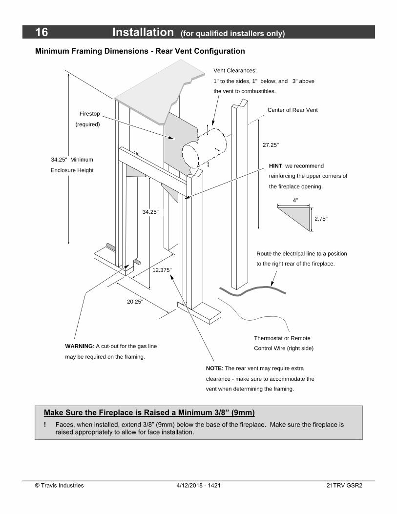
Minimum Framing Dimensions - Rear Vent Configuration
Make Sure the Fireplace is Raised a Minimum 3/8” (9mm)
! Faces, when installed, extend 3/8” (9mm) below the base of the fireplace. Make sure the fireplace is raised appropriately to allow for face installation.
��������
�����
������
���������
Route the electrical line to a position
to the right rear of the fireplace.
27.25"
Vent Clearances:
1" to the sides, 1" below, and 3" above
the vent to combustibles.
20.25"
34.25"
12.375"
Firestop
(required)
HINT: we recommend
reinforcing the upper corners of
the fireplace opening.
NOTE: The rear vent may require extra
clearance - make sure to accommodate the
vent when determining the framing.
Center of Rear Vent
���
�����������������
WARNING: A cut-out for the gas line
may be required on the framing.
Thermostat or Remote
Control Wire (right side)
34.25" Minimum
Enclosure Height
4"
2.75"
Installation (for qualified installers only) 17
© Travis Industries 4/12/2018 - 1421 21TRV GSR2
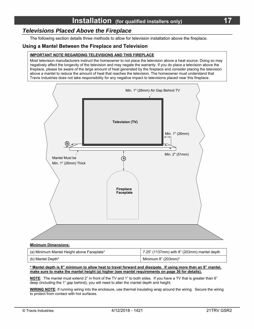
Televisions Placed Above the Fireplace The following section details three methods to allow for television installation above the fireplace.
Using a Mantel Between the Fireplace and Television
IMPORTANT NOTE REGARDING TELEVISIONS AND THIS FIREPLACE
Most television manufacturers instruct the homeowner to not place the television above a heat source. Doing so may negatively affect the longevity of the television and may negate the warranty. If you do place a television above the fireplace, please be aware of the large amount of heat generated by the fireplace and consider placing the television above a mantel to reduce the amount of heat that reaches the television. The homeowner must understand that Travis Industries does not take responsibility for any negative impact to televisions placed near this fireplace.
Minimum Dimensions:
(a) Minimum Mantel Height above Faceplate* 7.25” (1137mm) with 8” (203mm) mantel depth
(b) Mantel Depth* Minimum 8” (203mm)*
* Mantel depth is 8” minimum to allow heat to travel forward and dissipate. If using more than an 8” mantel, make sure to make the mantel height (a) higher (see mantel requirements on page 36 for details).
NOTE: The mantel must extend 2” in front of the TV and 1” to both sides. If you have a TV that is greater than 6” deep (including the 1” gap behind), you will need to alter the mantel depth and height.
WIRING NOTE: If running wiring into the enclosure, use thermal insulating wrap around the wiring. Secure the wiring to protect from contact with hot surfaces.
Min. 1" (26mm) Air Gap Behind TV
b
Min. 1" (26mm)
Television (TV)
Min. 2" (51mm)Mantel Must be
Min. 1" (26mm) Thick
a
Fireplace Faceplate
18 Installation (for qualified installers only)
© Travis Industries 4/12/2018 - 1421 21TRV GSR2
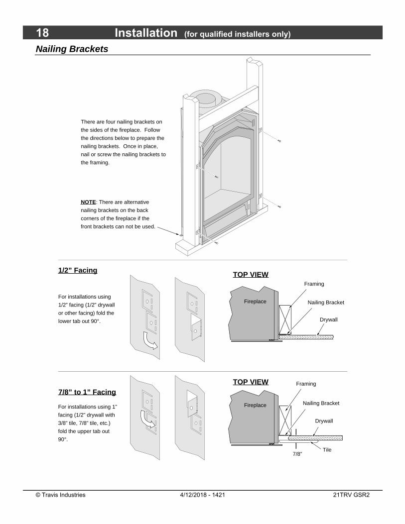
Nailing Brackets
For installations using 1”
facing (1/2” drywall with
3/8” tile, 7/8” tile, etc.)
fold the upper tab out
90°.
For installations using
1/2” facing (1/2” drywall
or other facing) fold the
lower tab out 90°.
�����������
Fireplace
Drywall
Framing
Nailing Bracket
TOP VIEW
Tile����������
Fireplace
Drywall
��������������
Framing
Nailing Bracket
TOP VIEW
1/2” Facing
7/8” to 1” Facing
There are four nailing brackets on
the sides of the fireplace. Follow
the directions below to prepare the
nailing brackets. Once in place,
nail or screw the nailing brackets to
the framing.
NOTE: There are alternative
nailing brackets on the back
corners of the fireplace if the
front brackets can not be used.
7/8”
Installation (for qualified installers only) 19
© Travis Industries 4/12/2018 - 1421 21TRV GSR2
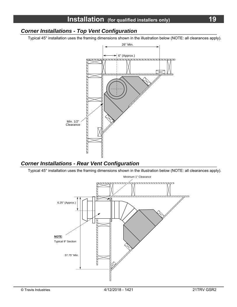
Corner Installations - Top Vent Configuration Typical 45° installation uses the framing dimensions shown in the illustration below (NOTE: all clearances apply).
Corner Installations - Rear Vent Configuration Typical 45° installation uses the framing dimensions shown in the illustration below (NOTE: all clearances apply).
26" Min.
������
�����������
�������������������������� 6" (Approx.)
Min. 1/2" Clearance
����������������������
�����������������������������������
������������
6.25" (Approx.)
������������
�������������������������������������������������������������������������������������������������������������������������
������������������������
37.75" Min.
Minimum 1" Clearance
NOTE:
Typical 9" Section
20 Installation (for qualified installers only)
© Travis Industries 4/12/2018 - 1421 21TRV GSR2
Outdoor Fireplace Installations
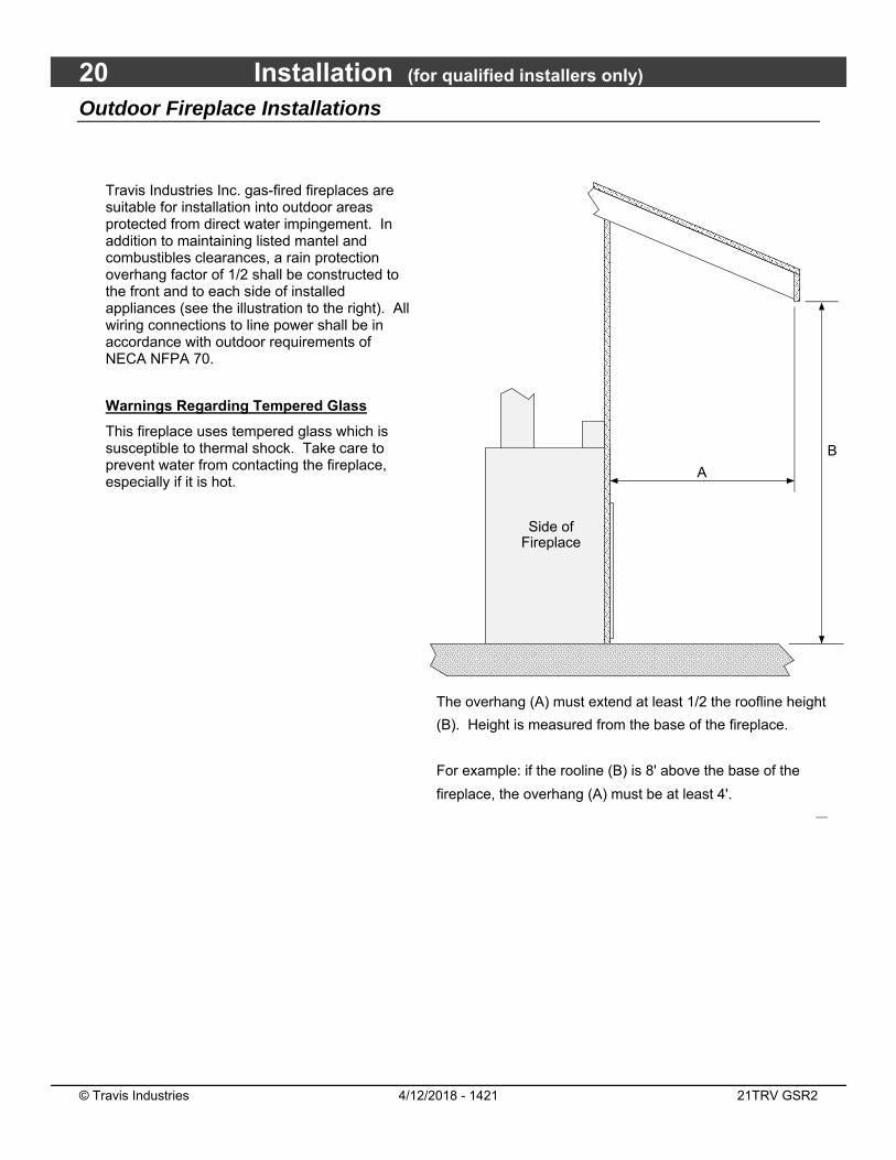
Travis Industries Inc. gas-fired fireplaces are suitable for installation into outdoor areas protected from direct water impingement. In addition to maintaining listed mantel and combustibles clearances, a rain protection overhang factor of 1/2 shall be constructed to the front and to each side of installed appliances (see the illustration to the right). All wiring connections to line power shall be in accordance with outdoor requirements of NECA NFPA 70.
Warnings Regarding Tempered Glass
This fireplace uses tempered glass which is susceptible to thermal shock. Take care to prevent water from contacting the fireplace, especially if it is hot.
��������������������������������������������������������������
��������������������������������������������������������������������������������������������������������
A
B
Side of Fireplace
The overhang (A) must extend at least 1/2 the roofline height
(B). Height is measured from the base of the fireplace.
For example: if the rooline (B) is 8' above the base of the
fireplace, the overhang (A) must be at least 4'.
������������������
������������������������������������������������������������������������������������������
Installation (for qualified installers only) 21
© Travis Industries 4/12/2018 - 1421 21TRV GSR2
Gas Line Requirements MASSACHUSETTS INSTALLATIONS - WARNING:
THIS PRODUCT MUST BE INSTALLED BY A LICENSED PLUMBER OR GAS FITTER WHEN INSTALLED WITHIN THE COMMONWEALTH OF MASSACHUSETTS.
OTHER MASSACHUSETTS CODE REQUIREMENTS:
Flexible connector must not be longer than 36 inches.
Shutoff valve must be a “T” handle gas cock.
Only direct vent sealed combustion products are approved for bedrooms or bathrooms.
Fireplace dampers must be removed or welded in the open position prior to the installation of a fireplace insert or gas log.
A carbon monoxide (CO) detector is required in the same room as the appliance.
The gas line must be installed in accordance with all local codes, if any; if not, follow ANSI 223.1 and the requirements listed below.
The fireplace and gas control valve must be disconnected from the gas supply piping during any pressure testing of that system at test pressures in excess of 1/2 psig. For pressures under 1/2 psig, isolate the gas supply piping by closing the manual shutoff valve.
Leak test all gas line joints and the gas control valve prior to and after starting the fireplace.
Fuel
This fireplace is designed either for natural gas or for propane (but not for both). Check the sticker on the top of the gas control valve to make sure the correct fuel is used.
Gas Line Connection
Installation must be performed by a qualified installer, service agency or the gas supplier (In Massachusetts a licensed plumber/gasfitter).
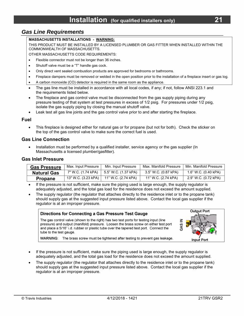
Gas Inlet Pressure
Gas Pressure Max. Input Pressure Min. Input Pressure Max. Manifold Pressure Min. Manifold Pressure
Natural Gas 7" W.C. (1.74 kPA) 5.5” W.C. (1.37 kPA) 3.5” W.C. (0.87 kPA) 1.6” W.C. (0.40 kPA)
Propane 13" W.C. (3.23 kPA) 11” W.C. (2.74 kPA) 11” W.C. (2.74 kPA) 2.9” W.C. (0.72 kPA)
If the pressure is not sufficient, make sure the piping used is large enough, the supply regulator is adequately adjusted, and the total gas load for the residence does not exceed the amount supplied.
The supply regulator (the regulator that attaches directly to the residence inlet or to the propane tank) should supply gas at the suggested input pressure listed above. Contact the local gas supplier if the regulator is at an improper pressure.
22 Installation (for qualified installers only)
© Travis Industries 4/12/2018 - 1421 21TRV GSR2
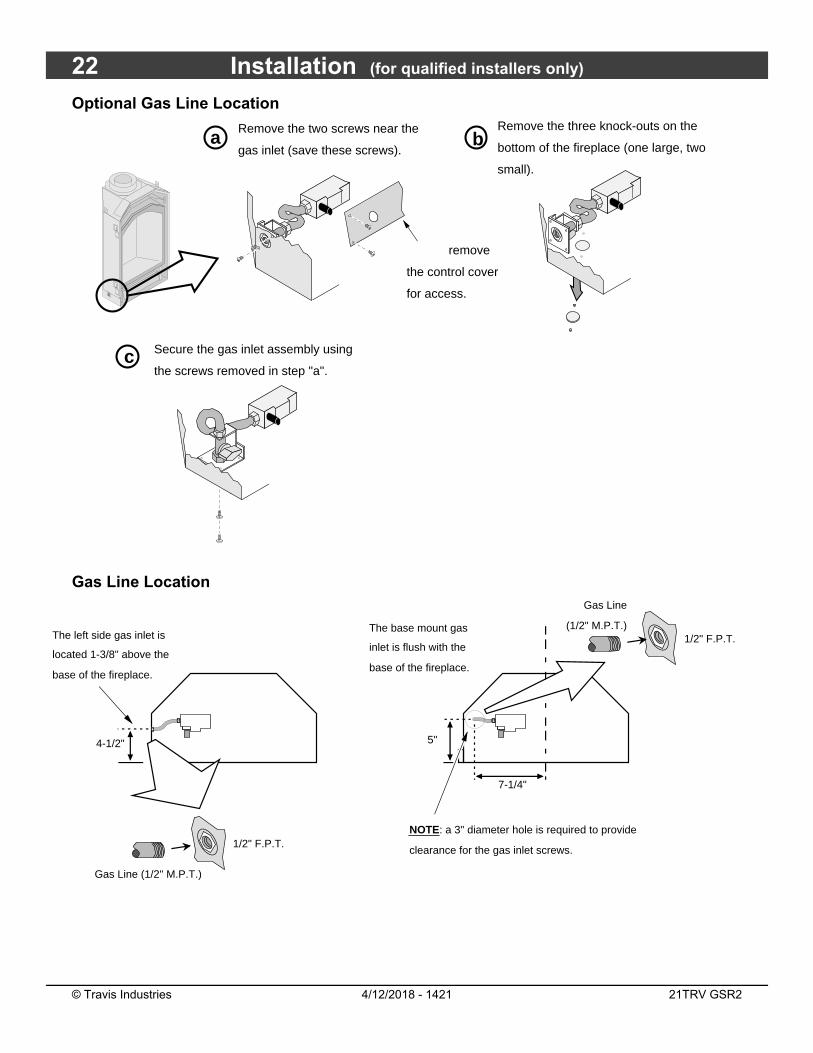
Optional Gas Line Location
Gas Line Location
Remove the three knock-outs on the
bottom of the fireplace (one large, two
small).
Remove the two screws near the
gas inlet (save these screws).
Secure the gas inlet assembly using
the screws removed in step "a".
a b
c
NOTE: remove
the control cover
for access.
The left side gas inlet is
located 1-3/8" above the
base of the fireplace.
1/2" F.P.T.
4-1/2"
Gas Line (1/2" M.P.T.)
The base mount gas
inlet is flush with the
base of the fireplace.
NOTE: a 3" diameter hole is required to provide
clearance for the gas inlet screws.
5"
7-1/4"
1/2" F.P.T.
Gas Line
(1/2" M.P.T.)

Installation (for qualified installers only) 23
© Travis Industries 4/12/2018 - 1421 21TRV GSR2
Electrical Connection (required) The electrical line to the grounded receptacle inside the fireplace must be installed by a qualified
installer and must meet all local codes.
Make sure the household breaker is shut off prior to working on any electrical lines.
The appliance, when installed, must be electrically grounded in accordance with local codes or, in the absence of local codes, with the National Electrical Code, ANSI/NFPA 70, or the Canadian Electrical Code, CSA C22.1.
The electrical line must be a min. 14 gauge, and supply 120 Volts at 60 Hz (2 Amps).
Caution: Label all wires prior to disconnection when servicing controls. Wiring errors can cause improper and dangerous operation.
d
Remove the cover from the
fireplace junction box.
The connection wires and a romex clamp
are inside the junction box.
Remove the knock-out from the cover plate.
NOTE: An alternative knock-out is
provided in the base of the
fireplace if you wish to run the
electrical line from below.
Secure the romex connector to the cover plate. Route
the electrical line through the cover plate and attach the
electrical leads. Replace the cover plate.
a b
c
24 Installation (for qualified installers only)
© Travis Industries 4/12/2018 - 1421 21TRV GSR2
Vent Requirements The gas appliance and vent system must be vented directly to the outside of the building, and never
be attached to a chimney serving a separate solid fuel or gas-burning appliance. Each direct vent gas appliance must use its own separate vent system.
In addition to the requirements listed here, follow the requirements provided with the vent.
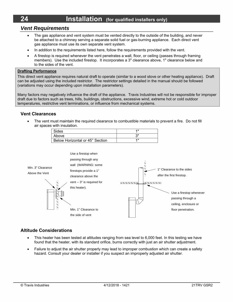
A firestop is required whenever the vent penetrates a wall, floor, or ceiling (passes through framing members). Use the included firestop. It incorporates a 3" clearance above, 1" clearance below and to the sides of the vent.
Drafting Performance
This direct vent appliance requires natural draft to operate (similar to a wood stove or other heating appliance). Draft can be adjusted using the included restrictor. The restrictor settings detailed in the manual should be followed (variations may occur depending upon installation parameters).
Many factors may negatively influence the draft of the appliance. Travis Industries will not be responsible for improper draft due to factors such as trees, hills, buildings, obstructions, excessive wind, extreme hot or cold outdoor temperatures, restrictive vent terminations, or influence from mechanical systems.
Vent Clearances
The vent must maintain the required clearance to combustible materials to prevent a fire. Do not fill air spaces with insulation.
Sides 1" Above 3" Below Horizontal or 45° Section 1"
Altitude Considerations
This heater has been tested at altitudes ranging from sea level to 6,000 feet. In this testing we have found that the heater, with its standard orifice, burns correctly with just an air shutter adjustment.
Failure to adjust the air shutter properly may lead to improper combustion which can create a safety hazard. Consult your dealer or installer if you suspect an improperly adjusted air shutter.
Use a firestop when
passing through any
wall (WARNING: some
firestops provide a 1"
clearance above the
vent -- 3" is required for
this heater).
Min. 3" Clearance
Above the Vent
�����
Min. 1" Clearance to
the side of vent
������������
1" Clearance to the sides
after the first firestop.
���
Use a firestop whenever
passing through a
ceiling, enclosure or
floor penetration.
Installation (for qualified installers only) 25
© Travis Industries 4/12/2018 - 1421 21TRV GSR2
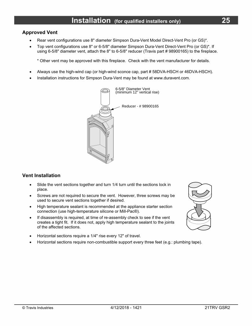
Approved Vent
Rear vent configurations use 8" diameter Simpson Dura-Vent Model Direct-Vent Pro (or GS)*.
Top vent configurations use 8" or 6-5/8" diameter Simpson Dura-Vent Direct-Vent Pro (or GS)*. If using 6-5/8" diameter vent, attach the 8" to 6-5/8" reducer (Travis part # 98900165) to the fireplace. * Other vent may be approved with this fireplace. Check with the vent manufacturer for details.
Always use the high-wind cap (or high-wind sconce cap, part # 58DVA-HSCH or 46DVA-HSCH).
Installation instructions for Simpson Dura-Vent may be found at www.duravent.com.
Vent Installation
Slide the vent sections together and turn 1/4 turn until the sections lock in place.
Screws are not required to secure the vent. However, three screws may be used to secure vent sections together if desired.
High temperature sealant is recommended at the appliance starter section connection (use high-temperature silicone or Mill-Pac®).
If disassembly is required, at time of re-assembly check to see if the vent creates a tight fit. If it does not, apply high temperature sealant to the joints of the affected sections.
Horizontal sections require a 1/4" rise every 12" of travel.
Horizontal sections require non-combustible support every three feet (e.g.: plumbing tape).
6-5/8" Diameter Vent (minimum 12" vertical rise)
Reducer - # 98900165
26 Installation (for qualified installers only)
© Travis Industries 4/12/2018 - 1421 21TRV GSR2
Approved Vent Configurations
Restrictor Position
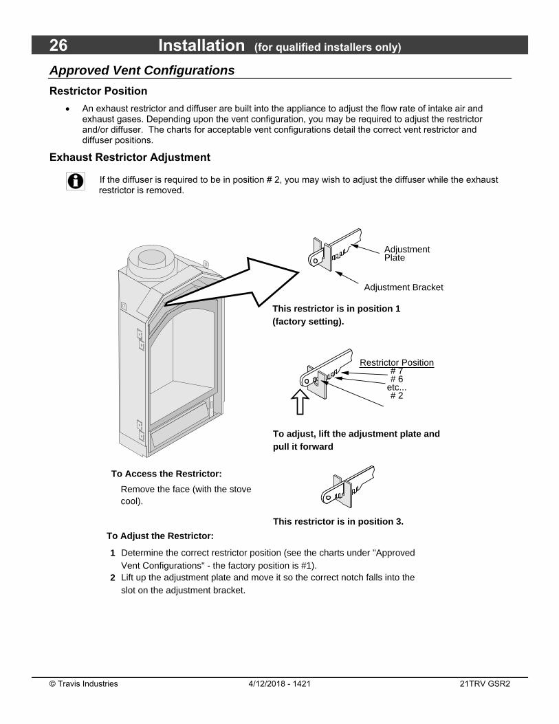
An exhaust restrictor and diffuser are built into the appliance to adjust the flow rate of intake air and exhaust gases. Depending upon the vent configuration, you may be required to adjust the restrictor and/or diffuser. The charts for acceptable vent configurations detail the correct vent restrictor and diffuser positions.
Exhaust Restrictor Adjustment
If the diffuser is required to be in position # 2, you may wish to adjust the diffuser while the exhaust restrictor is removed.
To Access the Restrictor:
Remove the face (with the stove cool).
1
2
Determine the correct restrictor position (see the charts under "Approved Vent Configurations" - the factory position is #1).Lift up the adjustment plate and move it so the correct notch falls into the slot on the adjustment bracket.
This restrictor is in position 1 (factory setting).
Adjustment Bracket
Adjustment Plate
To adjust, lift the adjustment plate and pull it forward
Restrictor Position# 7# 6
etc...# 2
This restrictor is in position 3.
To Adjust the Restrictor:
Installation (for qualified installers only) 27
© Travis Industries 4/12/2018 - 1421 21TRV GSR2
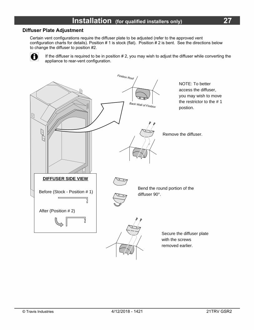
Diffuser Plate Adjustment
Certain vent configurations require the diffuser plate to be adjusted (refer to the approved vent configuration charts for details). Position # 1 is stock (flat). Position # 2 is bent. See the directions below to change the diffuser to position #2.
If the diffuser is required to be in position # 2, you may wish to adjust the diffuser while converting the appliance to rear-vent configuration.
NOTE: To better access the diffuser, you may wish to move the restrictor to the # 1 postion.
Remove the diffuser.
Secure the diffuser plate with the screws removed earlier.
Bend the round portion of the diffuser 90°.
��
Before (Stock - Position # 1)
After (Position # 2)
DIFFUSER SIDE VIEW
��������
Back Wall of Firebox
Firebox Roof
28 Installation (for qualified installers only)
© Travis Industries 4/12/2018 - 1421 21TRV GSR2
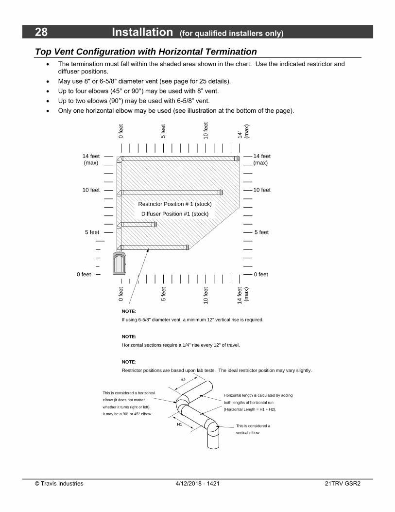
Top Vent Configuration with Horizontal Termination The termination must fall within the shaded area shown in the chart. Use the indicated restrictor and
diffuser positions.
May use 8" or 6-5/8" diameter vent (see page for 25 details).
Up to four elbows (45° or 90°) may be used with 8” vent.
Up to two elbows (90°) may be used with 6-5/8” vent.
Only one horizontal elbow may be used (see illustration at the bottom of the page).
������������������������������������������������������������������������������������������������������������
5 feet
10 feet
0 feet
0 fe
et
5 fe
et
5 feet
0 feet
0 fe
et
10 feet
5 fe
et
10 fe
et
14'
(max
)
10 fe
etRestrictor Position # 1 (stock)
Diffuser Position #1 (stock)
14 fe
et(m
ax)
14 feet(max)
14 feet(max)
NOTE:
If using 6-5/8" diameter vent, a minimum 12" vertical rise is required.
NOTE:
Horizontal sections require a 1/4" rise every 12" of travel.
NOTE:
Restrictor positions are based upon lab tests. The ideal restrictor position may vary slightly.
This is considered a horizontal
elbow (it does not matter
whether it turns right or left).
It may be a 90° or 45° elbow.
This is considered a
vertical elbow
Horizontal length is calculated by adding
both lengths of horizontal run
(Horizontal Length = H1 + H2).
H1
H2
Installation (for qualified installers only) 29
© Travis Industries 4/12/2018 - 1421 21TRV GSR2
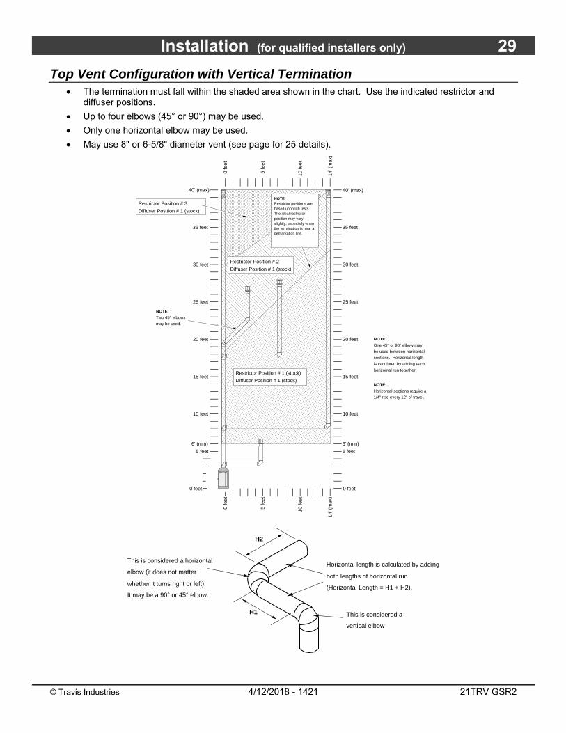
Top Vent Configuration with Vertical Termination The termination must fall within the shaded area shown in the chart. Use the indicated restrictor and
diffuser positions.
Up to four elbows (45° or 90°) may be used.
Only one horizontal elbow may be used.
May use 8" or 6-5/8" diameter vent (see page for 25 details).
Restrictor Position # 3
Diffuser Position # 1 (stock)
�������������������������������������������������������������������������������������������������������������������������������������������������������������������������������������������������������������������������������������������������������������������������������������������������������������������������������������
���������������������������������������������������������������������������������������������������������������������
����������������������������������������������������������������������������������������������������������������������������������������������������������������������������������������������������������������������������������������������������������������������������������������������
5 feet
10 feet
15 feet
20 feet
25 feet
30 feet
0 feet
40' (max)
5 fe
et
10 fe
et
0 fe
et
5 fe
et
10 fe
et
14' (
max
)
15 feet
20 feet
25 feet
30 feet
0 feet
0 fe
et
NOTE:
Horizontal sections require a
1/4" rise every 12" of travel.
10 feet
40' (max)
14' (
max
)
NOTE:Restrictor positions are based upon lab tests. The ideal restrictor position may vary slightly, especially when the termination is near a demarkation line.
5 feet
NOTE:
One 45° or 90° elbow may
be used between horizontal
sections. Horizontal length
is caculated by adding each
horizontal run together.
35 feet35 feet
Restrictor Position # 1 (stock)
Diffuser Position # 1 (stock)
6' (min) 6' (min)
NOTE:
Two 45° elbows
may be used.
Restrictor Position # 2
Diffuser Position # 1 (stock)
This is considered a horizontal
elbow (it does not matter
whether it turns right or left).
It may be a 90° or 45° elbow.
This is considered a
vertical elbow
Horizontal length is calculated by adding
both lengths of horizontal run
(Horizontal Length = H1 + H2).
H1
H2
30 Installation (for qualified installers only)
© Travis Industries 4/12/2018 - 1421 21TRV GSR2
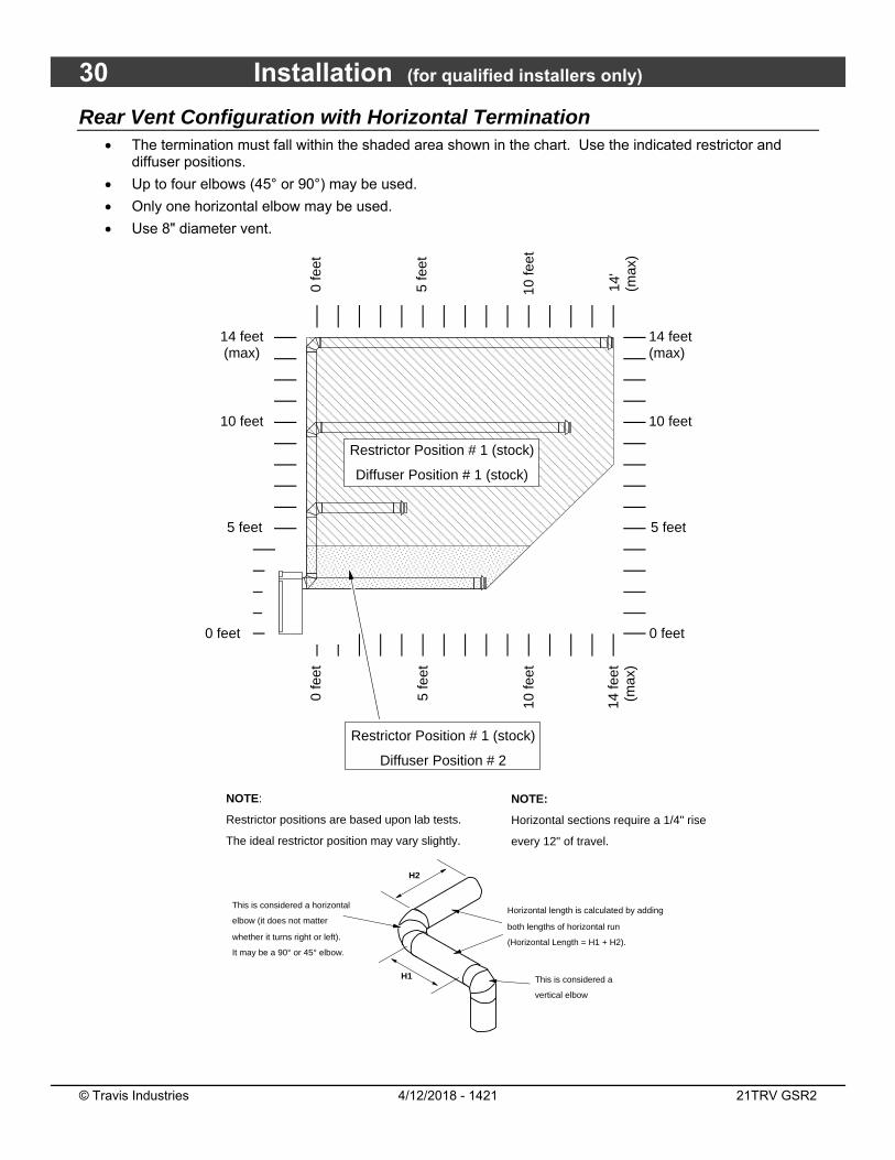
Rear Vent Configuration with Horizontal Termination The termination must fall within the shaded area shown in the chart. Use the indicated restrictor and
diffuser positions.
Up to four elbows (45° or 90°) may be used.
Only one horizontal elbow may be used.
Use 8" diameter vent.
������������������������������������������������������������������������������������������������������������������������
������������������
5 feet
10 feet
0 feet
0 fe
et
5 fe
et
5 feet
0 feet
0 fe
et
10 feet5
feet
10 fe
et
14'
(max
)
10 fe
et
14 fe
et(m
ax)
NOTE:
Horizontal sections require a 1/4" rise
every 12" of travel.
14 feet(max)
14 feet(max)
NOTE:
Restrictor positions are based upon lab tests.
The ideal restrictor position may vary slightly.
Restrictor Position # 1 (stock)
Diffuser Position # 1 (stock)
Restrictor Position # 1 (stock)
Diffuser Position # 2
This is considered a horizontal
elbow (it does not matter
whether it turns right or left).
It may be a 90° or 45° elbow.
This is considered a
vertical elbow
Horizontal length is calculated by adding
both lengths of horizontal run
(Horizontal Length = H1 + H2).
H1
H2

Installation (for qualified installers only) 31
© Travis Industries 4/12/2018 - 1421 21TRV GSR2
Rear Vent Configuration with Vertical Termination The termination must fall within the shaded area shown in the chart. Use the indicated restrictor and
diffuser positions.
Up to four elbows (45° or 90°) may be used.
Use 8" diameter vent.
Only one horizontal elbow may be used.
Restrictor Position # 3Diffuser Position # 1 (stock)
�������������������������������������������������������������������������������������������������������������������������������������������������������������������������������������������������������������������������������������������������������������
���������������������������������������������������������������������������������������������������
������������������������������������������������������������������������������������������������������������������������������������������������������������������������������������������������������
5 feet
10 feet
15 feet
20 feet
25 feet
30 feet
0 feet
40' (max)
5 fe
et
10 fe
et
0 fe
et
5 fe
et
10 fe
et
14' (
max
)
15 feet
20 feet
25 feet
30 feet
0 feet
0 fe
et
NOTE: Horizontal sections require a 1/4" rise every 12" of travel.
10 feet
40' (max)
14' (
max
)
NOTE:Restrictor positions are based upon lab tests. The ideal restrictor position may vary slightly, especially when the termination is near a demarkation line.
5 feet
NOTE: One 45° or 90° elbow may be used between horizontal sections. Horizontal length is caculated by adding each horizontal run together.
35 feet35 feet
6' (min) 6' (min)
NOTE: Two 45° elbows may be used.
Restrictor Position # 1 (stock)Diffuser Position # 1 (stock)
Restrictor Position # 2Diffuser Position # 1 (stock)
This is considered a horizontal
elbow (it does not matter
whether it turns right or left).
It may be a 90° or 45° elbow.
This is considered a
vertical elbow
Horizontal length is calculated by adding
both lengths of horizontal run
(Horizontal Length = H1 + H2).
H1
H2

32 Installation (for qualified installers only)
© Travis Industries 4/12/2018 - 1421 21TRV GSR2
Termination Requirements ! Venting terminals shall not be recessed into a wall or siding.
A Minimum 9" clearance from any door or window
B Minimum 12" above any grade, veranda, porch, deck or balcony
C Minimum 1" from outside corner walls NOTE: Clearance in accordance with local installation codes and the requirements of the gas supplier.
D Minimum 1" from inside corner walls NOTE: Clearance in accordance with local installation codes and the requirements of the gas supplier.
E Minimum 11" clearance below unventilated soffits or roof surfaces
Minimum 18" clearance below ventilated soffits Minimum 6" clearance below roof eaves NOTE: Vinyl surfaces require 24" NOTE: Clearance in accordance with local installation codes and the requirements of the gas supplier.
F Minimum 12" clearance below a veranda, porch, deck or balcony NOTE: Permitted only if veranda, porch, deck, or balcony is fully open on a minumum of two sides beneath the floor. NOTE: Clearance in accordance with local installation codes and the requirements of the gas supplier.
G Minimum 48" clearance from any adjacent building
H Minimum 84" clearance above any grade when adjacent to public walkways or driveways NOTE: may not be used over a walkway or driveway shared by an adjacent building
I Minimum 9" clearance to any nonmechanical air supply inlet to the building or the combustion air inlet to any other appliance.
J Minimum 36" clearance above any mechanical air supply inlet if within 10’ horizontally
K Minimum 36" from the area above the meter/regulator (vent outlet) - this extends 15’ above the regulator NOTE: Clearance in accordance with local installation codes and the requirements of the gas supplier.
L Minimum 36" from the meter/regulator (vent outlet) NOTE: Clearance in accordance with local installation codes and the requirements of the gas supplier.
M Minimum 12” above the roof line (for vertical terminations)
N Minimum 24” horizontal clearance to any surface (such as an exterior wall) – for vertical terminations
• Use the vinyl siding standoff when installing on an exterior with vinyl siding.
• Vent termination must not be located where it will become plugged by snow or other material.
11” Min.
6” Min.
Roof Surface
Roof Eaves
C
B
H
E
G A
DF
L
K J
I
NOTE: Measure clearances to the nearest edge of the exhaust hood.
AE
E
M
N
Installation (for qualified installers only) 33
© Travis Industries 4/12/2018 - 1421 21TRV GSR2
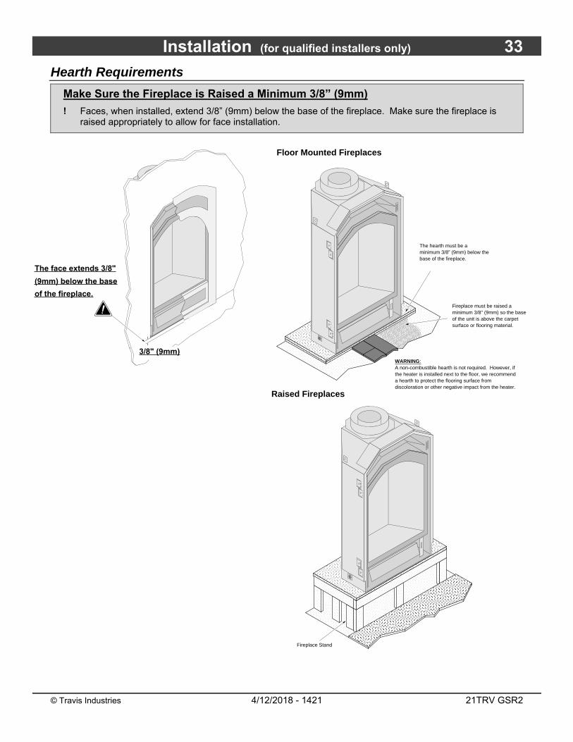
Hearth Requirements
Make Sure the Fireplace is Raised a Minimum 3/8” (9mm)
! Faces, when installed, extend 3/8” (9mm) below the base of the fireplace. Make sure the fireplace is raised appropriately to allow for face installation.
The face extends 3/8"
(9mm) below the base
of the fireplace.
3/8" (9mm)
Floor Mounted Fireplaces
Raised Fireplaces
����������������������������������������������������������������������������������������������������������������������������������������������������������������������������������������������������������������������������������������������������������������������������������������������
��������
���� ��
������
���
��������
����
��������
����
��������
����
���
������������������������������������������������������������������������������������������������������������
����������������������������������������������������������������������������������������������������������������������������������������������������������������
������������������������������������������������������������������������������������
��������������������������������������������������������������������������������������������������������������������������������������������������������������������������
������������������������
������������������������������
Fireplace Stand
��������
����
The hearth must be a minimum 3/8” (9mm) below the base of the fireplace.
Fireplace must be raised a minimum 3/8” (9mm) so the base of the unit is above the carpet surface or flooring material.
��������������������������������������������������������������������������������������������������������������������������������������������������������������������������������������������������������������������������������������������������������������������������������������������������������������������
�������������������������������������������������������������������������������������������
������������������������������������������������������������������������������������������������������������������������������������������������������������������������������������
������������������������
������������������������������������������������������������������������
WARNING:A non-combustible hearth is not required. However, if the heater is installed next to the floor, we recommend a hearth to protect the flooring surface from discoloration or other negative impact from the heater.
��������������������������������������������������������������������������������������������������������
������������������������������������������������������������������������������������������������������������������������������������������������������������������������������������������������������
������������������������
34 Installation (for qualified installers only)
© Travis Industries 4/12/2018 - 1421 21TRV GSR2
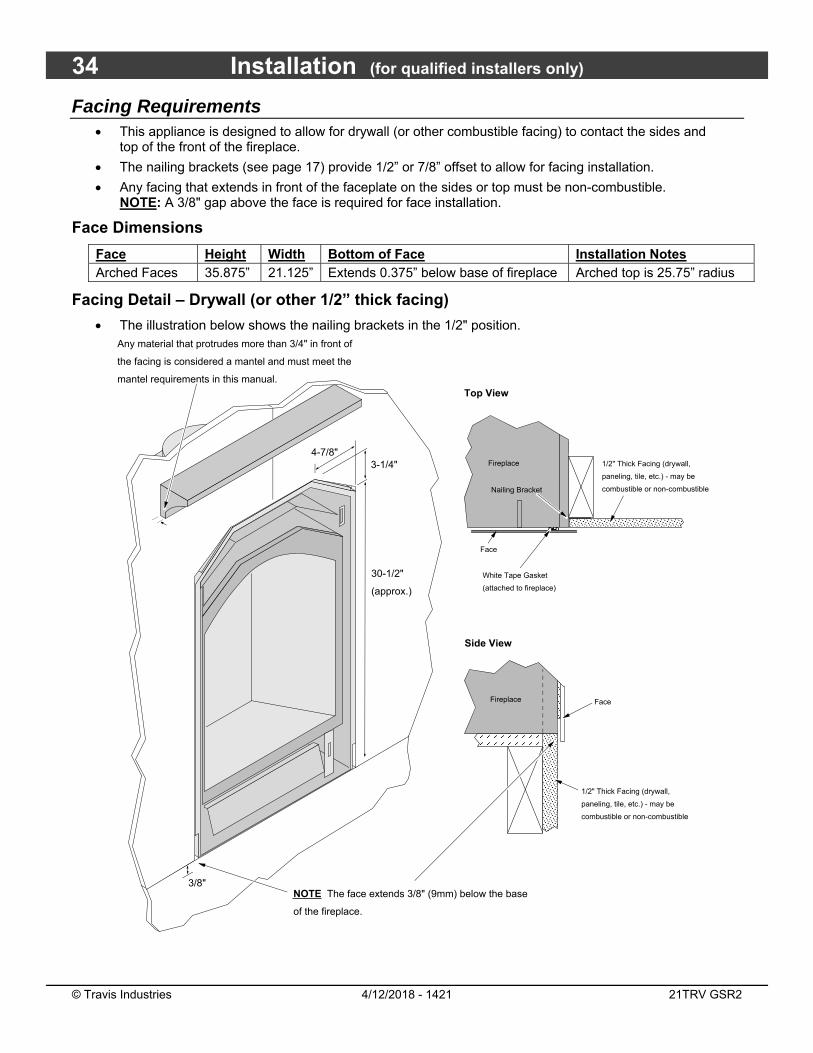
Facing Requirements This appliance is designed to allow for drywall (or other combustible facing) to contact the sides and
top of the front of the fireplace.
The nailing brackets (see page 17) provide 1/2” or 7/8” offset to allow for facing installation.
Any facing that extends in front of the faceplate on the sides or top must be non-combustible. NOTE: A 3/8" gap above the face is required for face installation.
Face Dimensions
Face Height Width Bottom of Face Installation Notes Arched Faces 35.875” 21.125” Extends 0.375” below base of fireplace Arched top is 25.75” radius
Facing Detail – Drywall (or other 1/2” thick facing)
The illustration below shows the nailing brackets in the 1/2" position.
Any material that protrudes more than 3/4" in front of
the facing is considered a mantel and must meet the
mantel requirements in this manual.
4-7/8"
30-1/2"
(approx.)
3-1/4"
NOTE The face extends 3/8" (9mm) below the base
of the fireplace.
3/8"
Top View
Side View
��������
Fireplace
������
Face
1/2" Thick Facing (drywall,
paneling, tile, etc.) - may be
combustible or non-combustible
White Tape Gasket
(attached to fireplace)
�������Face
Fireplace
Nailing Bracket
1/2" Thick Facing (drywall,
paneling, tile, etc.) - may be
combustible or non-combustible
Installation (for qualified installers only) 35
© Travis Industries 4/12/2018 - 1421 21TRV GSR2
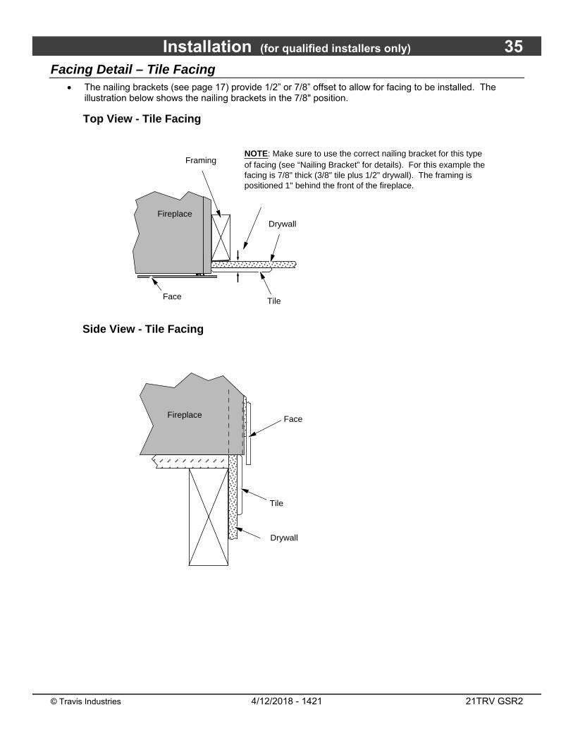
Facing Detail – Tile Facing The nailing brackets (see page 17) provide 1/2” or 7/8” offset to allow for facing to be installed. The
illustration below shows the nailing brackets in the 7/8" position.
Top View - Tile Facing
Side View - Tile Facing
��������
���
Fireplace
����������
����
Tile
Drywall
Face
Tile
NOTE: Make sure to use the correct nailing bracket for this type of facing (see “Nailing Bracket” for details). For this example the facing is 7/8" thick (3/8" tile plus 1/2" drywall). The framing is positioned 1" behind the front of the fireplace.
������
FireplaceDrywall
����
Framing
Face
36 Installation (for qualified installers only)
© Travis Industries 4/12/2018 - 1421 21TRV GSR2
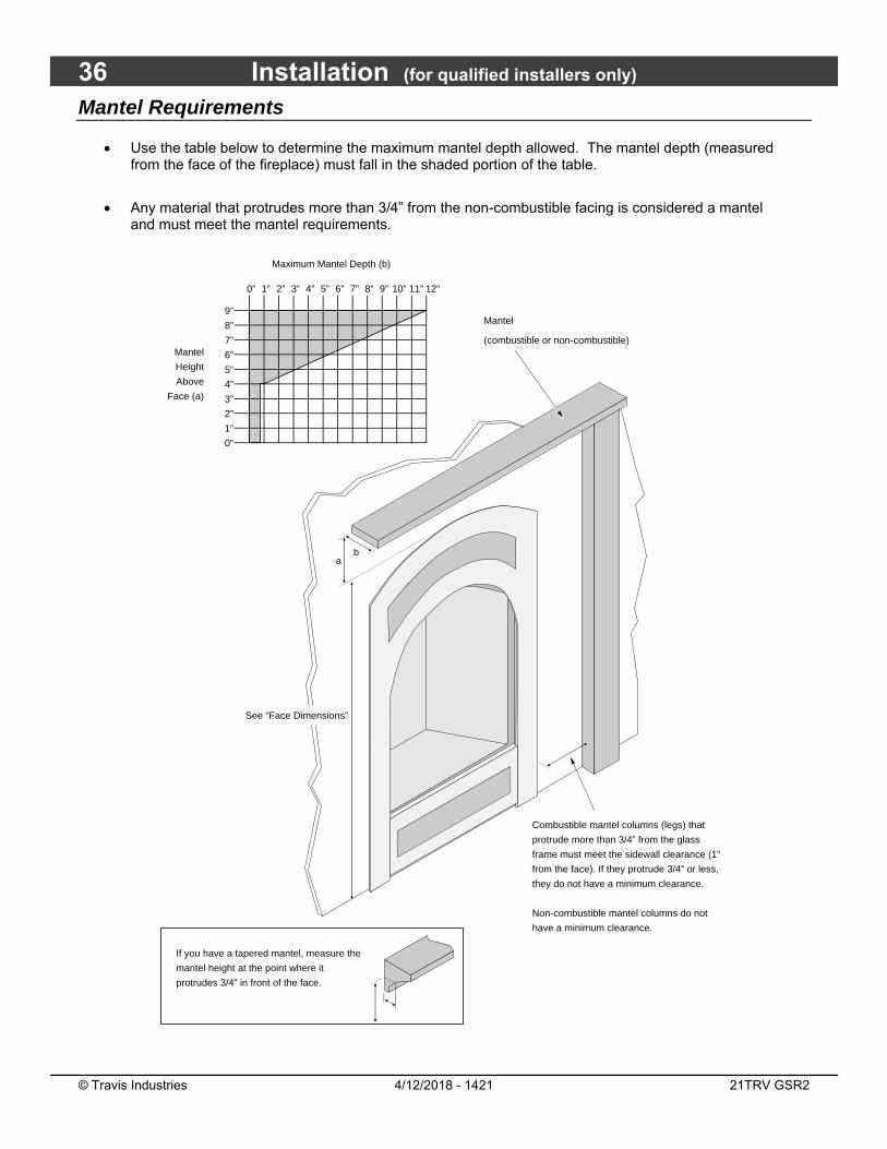
Mantel Requirements
Use the table below to determine the maximum mantel depth allowed. The mantel depth (measured from the face of the fireplace) must fall in the shaded portion of the table.
Any material that protrudes more than 3/4” from the non-combustible facing is considered a mantel and must meet the mantel requirements.
ab
If you have a tapered mantel, measure the
mantel height at the point where it
protrudes 3/4” in front of the face.
Maximum Mantel Depth (b)
Mantel
Height
Above
Face (a)
0”
1”
2”
8”
7”
6”
5”
4”
3”
9”
0” 1” 2” 3” 4” 5” 6” 7” 8” 9” 10” 11” 12”
See “Face Dimensions”
Combustible mantel columns (legs) that
protrude more than 3/4” from the glass
frame must meet the sidewall clearance (1”
from the face). If they protrude 3/4” or less,
they do not have a minimum clearance.
Non-combustible mantel columns do not
have a minimum clearance.
Mantel
(combustible or non-combustible)

Finalizing the Installation (for qualified installers only) 37
© Travis Industries 4/12/2018 - 1421 21TRV GSR2
Steps for Finalizing the Installation 1. Remove the glass (see page 39).
NOTE: If using propane (LP) convert the appliance prior to installing the logs. 2. We recommend you purge the gas line at this time (with the glass removed). This allows gas to be
detected once it enters the firebox, ensuring gas does not build up. 3. Make sure the accent light bulb is in place.
NOTE: Take care to not touch the bulb with your fingers (use a cloth or paper towel).
4. Install the four AA batteries (see illustration below). The AA batteries act as a power backup in case
the household (AC) power goes out and are required for operation. Install three AAA batteries into the remote (see illustration below). Synchronize the transmitter to the IFC (see the Owner’s Manual for details).
AAA Battery
AAA Battery
°F
AAA Battery AA Battery
AA Battery
AA Battery
AA Battery

38 Finalizing the Installation (for qualified installers only)
© Travis Industries 4/12/2018 - 1421 21TRV GSR2
5. Install the logs (see page 42). 6. Replace the glass. 7. Start the heater. 8. Leak test all gas joints. 9. Check the air shutter following the directions below.
Air Shutter Adjustment Let the heater burn for fifteen minutes (make sure the logs and glass are in place). The flames should be yellow with no sooting. Adjust the air shutter, if necessary, to achieve the correct looking flame.
10. Turn the flame adjust knob to its highest position - the flames should not contact the top of the firebox. Check the flame on low position. The flames should burn off of each burner hole. If the heater does not work correctly, contact your Travis dealer for a remedy.
FELT TABS FOR CONCEALMENT COVER
11. Give this manual to the home owner for future reference and fully explain operation of this heater. For comprehensive operating and maintenance instructions, refer to the Owner's Manual (part # 100-01305).
ACID WASH WARNING: Before installing the faceplate, make sure any masonry that has been treated with acid wash has been properly neutralized (this is used primarily with brick faces). Acid wash (muriatic acid) is used to remove excess mortar. If not properly neutralized with an ammonia solution, the plated face may develop a permanent tarnish when the acid evaporates over time. Contact your dealer if uncertain your facing has been properly neutralized.
NOTE: If the air shutter is all the way open, yet the flames remain sooty, shut off gas to the fireplace and contact a qualified gas service technician.
CorrectFlames should be blue at the base, yellow-orange on the top.
If the flames are too tall or sooty on the ends, open the air shutter.
Not Enough AirIf the flames are all blue and short, close the air shutter.
Too Much Air
NOTE: The logs must be installed correctly to monitor the flame while adjusting the air shutter.
Moving the air shutter control to the right gives the flame less air (closed) - making it more orange. Moving it to the left gives the flame more air (open), making it more blue. For fine adjustments use a screwdriver to tap the air shutter.
ADJUSTING THE AIR SHUTTER Less Air
More Air
Phillips Screwdriver
Air Shutter Control
Certain faces may
contact the
concealment cover
when it is open.
Place the two felt
tabs (included in
owner's pack) on the
concealment cover
to prevent
scratching.
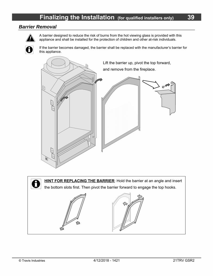
Finalizing the Installation (for qualified installers only) 39
© Travis Industries 4/12/2018 - 1421 21TRV GSR2
Barrier Removal
A barrier designed to reduce the risk of burns from the hot viewing glass is provided with this appliance and shall be installed for the protection of children and other at-risk individuals.
If the barrier becomes damaged, the barrier shall be replaced with the manufacturer’s barrier for this appliance.
HINT FOR REPLACING THE BARRIER: Hold the barrier at an angle and insert
the bottom slots first. Then pivot the barrier forward to engage the top hooks.
Lift the barrier up, pivot the top forward,
and remove from the fireplace.

40 Finalizing the Installation (for qualified installers only)
© Travis Industries 4/12/2018 - 1421 21TRV GSR2
Glass Frame Removal and Installation Warning: The appliance must be completely cool before removing the glass.
Warning: Do not strike or slam the glass.
Note: Remove the barrier before removing the glass (see previous page). Replace barrier after replacing the glass.
Open the two latches holding the glass
frame in place - follow the directions
shown to the right.
a
Glass Frame
Tilt the glass frame forward then lift it up. The tabs
on the glass frame will disengage from the slots on
the glass frame brackets attached to the fireplace.
b
Re-Attaching the Glass Frame:
a) Tilt the glass frame as shown above.
b) Insert the tabs on the glass frame into the slots on the glass frame brackets (attached to the fireplace).
c) Attach the two glass latches.
NOTE: Make sure the glass frame is all the way in place - it should be flush with the front of the fireplace
when installed.
Glass
Top of
Firebox
Latch
Catch
(on glass frame)Glass Frame Brackets
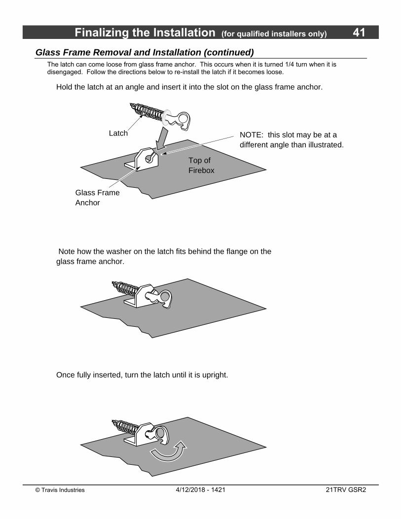
Finalizing the Installation (for qualified installers only) 41
© Travis Industries 4/12/2018 - 1421 21TRV GSR2
Glass Frame Removal and Installation (continued) The latch can come loose from glass frame anchor. This occurs when it is turned 1/4 turn when it is disengaged. Follow the directions below to re-install the latch if it becomes loose.
Top of Firebox
Hold the latch at an angle and insert it into the slot on the glass frame anchor.
NOTE: this slot may be at a different angle than illustrated.
Note how the washer on the latch fits behind the flange on the glass frame anchor.
Glass Frame Anchor
Once fully inserted, turn the latch until it is upright.
Latch
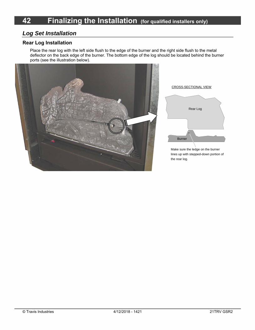
42 Finalizing the Installation (for qualified installers only)
© Travis Industries 4/12/2018 - 1421 21TRV GSR2
Log Set Installation
Rear Log Installation
Place the rear log with the left side flush to the edge of the burner and the right side flush to the metal deflector on the back edge of the burner. The bottom edge of the log should be located behind the burner ports (see the illustration below).
Rear Log
Burner
Make sure the ledge on the burner
lines up with stepped-down portion of
the rear log.
CROSS-SECTIONAL VIEW
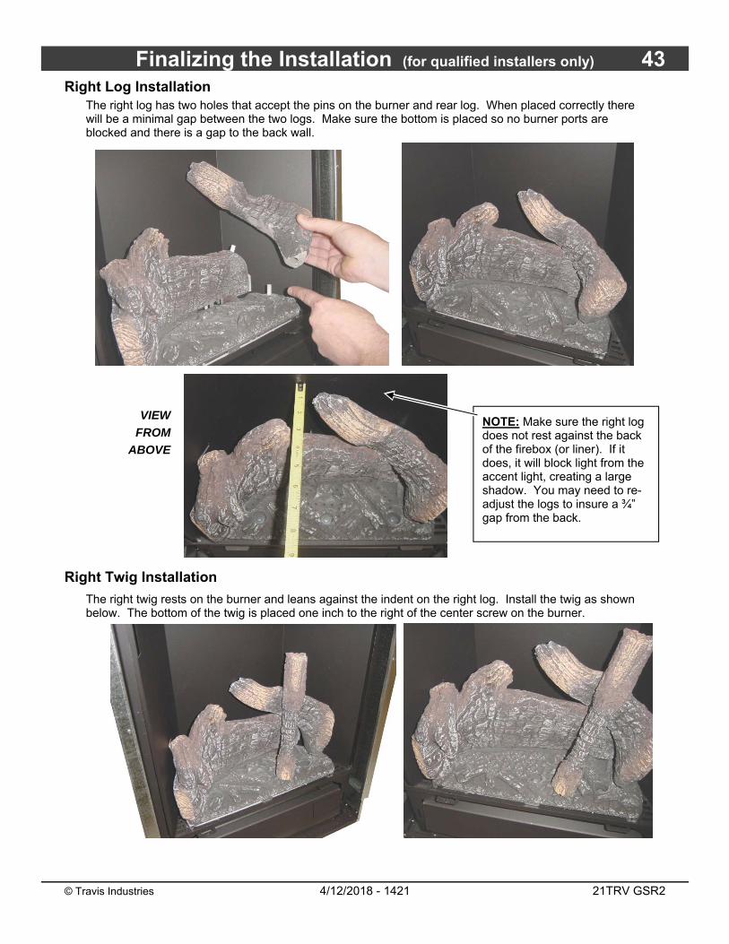
Finalizing the Installation (for qualified installers only) 43
© Travis Industries 4/12/2018 - 1421 21TRV GSR2
Right Log Installation The right log has two holes that accept the pins on the burner and rear log. When placed correctly there will be a minimal gap between the two logs. Make sure the bottom is placed so no burner ports are blocked and there is a gap to the back wall.
VIEW
FROM
ABOVE
Right Twig Installation
The right twig rests on the burner and leans against the indent on the right log. Install the twig as shown below. The bottom of the twig is placed one inch to the right of the center screw on the burner.
NOTE: Make sure the right log does not rest against the back of the firebox (or liner). If it does, it will block light from the accent light, creating a large shadow. You may need to re-adjust the logs to insure a ¾” gap from the back.
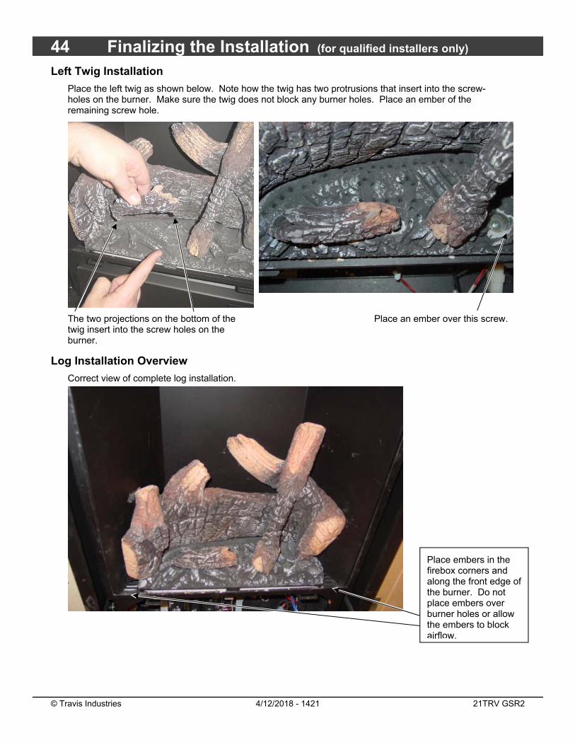
44 Finalizing the Installation (for qualified installers only)
© Travis Industries 4/12/2018 - 1421 21TRV GSR2
Left Twig Installation
Place the left twig as shown below. Note how the twig has two protrusions that insert into the screw-holes on the burner. Make sure the twig does not block any burner holes. Place an ember of the remaining screw hole.
The two projections on the bottom of the twig insert into the screw holes on the burner.
Place an ember over this screw.
Log Installation Overview
Correct view of complete log installation.
Place embers in the firebox corners and along the front edge of the burner. Do not place embers over burner holes or allow the embers to block airflow.

Finalizing the Installation (for qualified installers only) 45
© Travis Industries 4/12/2018 - 1421 21TRV GSR2
LP Conversion Instructions The GSR Stepper Motor Kit (SKU 94400999) is required for converting this appliance to LP. The kit contains the stepper motor (regulator), torx wrench, and pilot orifice.
WARNING
This conversion kit shall be installed by a qualified service agency in accordance with the manufacturer’s instructions and all applicable codes and requirements of the authority having jurisdiction. If the information in these instructions is not followed exactly, a fire, explosion or production of carbon monoxide may result causing property damage, personal injury or loss of life. The qualified service agency is responsible for the proper installation of this kit. The installation is not proper and complete until the operation of the converted appliance is checked as specified in the manufacturer’s instructions supplied with the kit.
CAUTION:
The gas supply shall be shut off prior to disconnecting the electrical power, before proceeding with the conversion.
IMPORTANT:
A converted appliance must have a label attached marked with the following:
“This appliance was converted to _____ gas with Kit No. _____ by _____ (name and address of organization making the conversion), which accepts the responsibility that this conversion has been properly made. This control has been converted for use with gas_____.”
Install the conversion kit prior to installing the gas line to ensure proper gas use.
1 Remove the glass (see page 37). Remove the logs and embers (if installed - page 42)
2 Remove the burner following the directions below.
Lift the burner directly
up to remove.
����
����
Burner Replacement:
Make sure the burner manifold
inserts over the front (left) orifice.
Make sure the burner is fully seated and pilot hood lines up
with the burner holes at the rear edge of the burner.
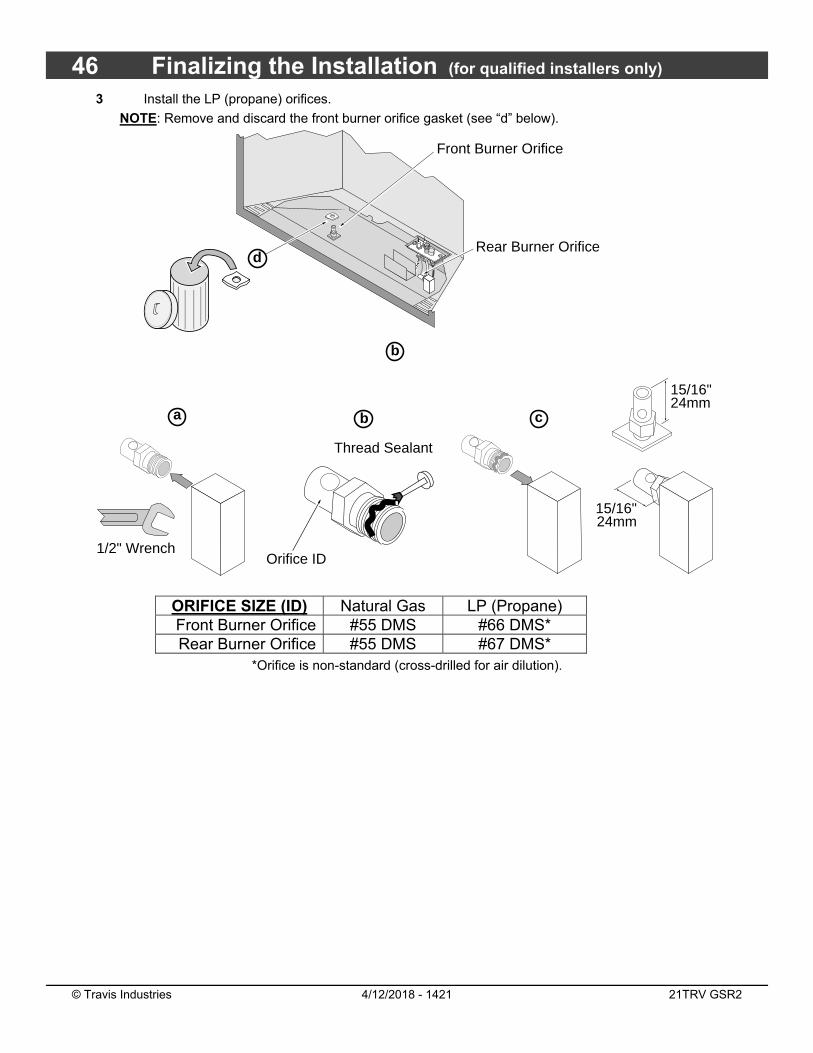
46 Finalizing the Installation (for qualified installers only)
© Travis Industries 4/12/2018 - 1421 21TRV GSR2
3 Install the LP (propane) orifices.
NOTE: Remove and discard the front burner orifice gasket (see “d” below).
ORIFICE SIZE (ID) Natural Gas LP (Propane) Front Burner Orifice #55 DMS #66 DMS* Rear Burner Orifice #55 DMS #67 DMS*
*Orifice is non-standard (cross-drilled for air dilution).
Front Burner Orifice
a
Rear Burner Orifice
b
Orifice ID
Thread Sealant
1/2" Wrench
������
b
15/16"24mm
15/16"24mm
c
d
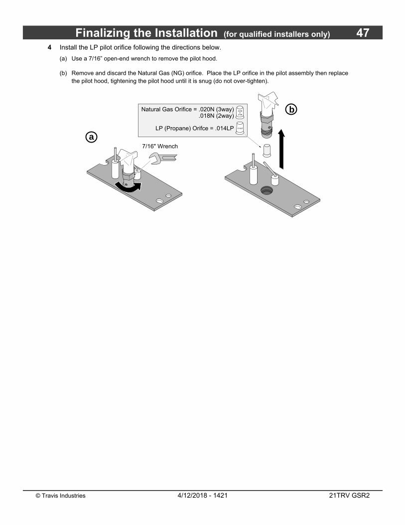
Finalizing the Installation (for qualified installers only) 47
© Travis Industries 4/12/2018 - 1421 21TRV GSR2
4 Install the LP pilot orifice following the directions below.
(a) Use a 7/16” open-end wrench to remove the pilot hood.
(b) Remove and discard the Natural Gas (NG) orifice. Place the LP orifice in the pilot assembly then replace the pilot hood, tightening the pilot hood until it is snug (do not over-tighten).
a
b
7/16" Wrench
Natural Gas Orifice = .020N (3way).018N (2way)
LP (Propane) Orifce = .014LP
.020Nor
.018N
.014LP
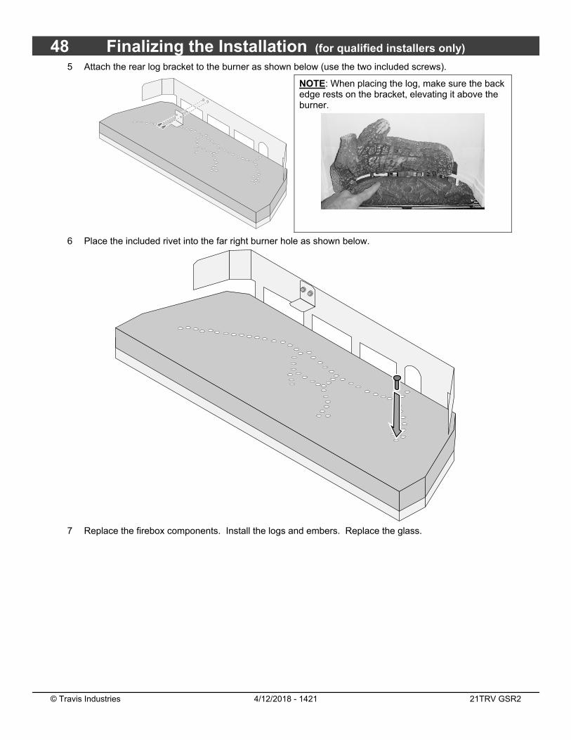
48 Finalizing the Installation (for qualified installers only)
© Travis Industries 4/12/2018 - 1421 21TRV GSR2
5 Attach the rear log bracket to the burner as shown below (use the two included screws).
NOTE: When placing the log, make sure the back edge rests on the bracket, elevating it above the burner.
6 Place the included rivet into the far right burner hole as shown below.
7 Replace the firebox components. Install the logs and embers. Replace the glass.

Finalizing the Installation (for qualified installers only) 49
© Travis Industries 4/12/2018 - 1421 21TRV GSR2
8 Remove the control cover to access the gas control valve. Disconnect the NG stepper motor wire from the IFC.
9 The stepper motor (adjustable regulator) has an installation sheet included with it – make sure to follow all of the directions. Place the stepper motor on the gas control valve– MAKE SURE IT IS CORRECTLY ORIENTED. Secure using the screws included with the motor– tighten to 25 Lb-inches. Leak test this area after installation to verify proper installation.
10 Restore the appliance to the correct configuration. Make the gas line connection, bleed the gas line (if applicable), start the heater and thoroughly leak-test all gas connections and the gas control valve.
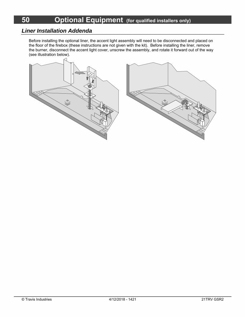
50 Optional Equipment (for qualified installers only)
© Travis Industries 4/12/2018 - 1421 21TRV GSR2
Liner Installation Addenda
Before installing the optional liner, the accent light assembly will need to be disconnected and placed on the floor of the firebox (these instructions are not given with the kit). Before installing the liner, remove the burner, disconnect the accent light cover, unscrew the assembly, and rotate it forward out of the way (see illustration below).
����
��
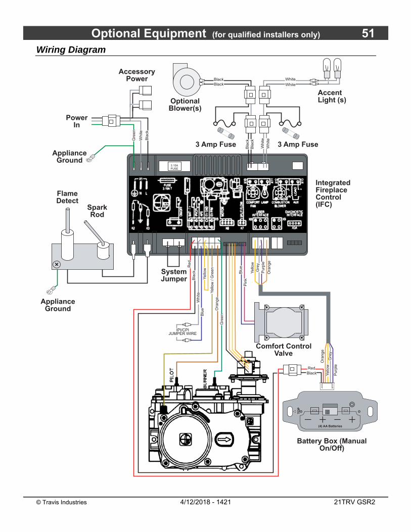
Optional Equipment (for qualified installers only) 51
© Travis Industries 4/12/2018 - 1421 21TRV GSR2
Wiring Diagram
Ora
nge
Yel
low
System Jumper
Pur
ple
Gre
y
Pilot Sensor
Spark Rod
Comfort Control Valve
Battery Box (Manual On/Off)
Accent Light (s)
3 Amp Fuse
Optional Blower(s)
3 Amp FuseAppliance
Ground
Accessory Power
Appliance Ground
Gre
enO
rang
eY
ello
w /
Gre
en
Whi
teB
lue
IPI/CPI JUMPER WIRE
Blu
eP
ink
Power In
TO
P
(4) AA Batteries
Bla
ckR
ed
Yel
low
Ora
nge
Yel
low
Flame Detect
BlackRed
Pur
ple
Gre
y
Bla
ck
Whi
te
Gre
en
Integrated Fireplace Control(IFC)
3.15AFUSE
Whi
te
Bla
ck
Whi
te
Bla
ck
BlackBlack
WhiteWhite
52 Index
© Travis Industries 4/12/2018 - 1421 21TRV GSR2
Index
Additional Items Required .................................. 7 Approved Vent Configurations ......................... 26 Barrier Removal ............................................... 39 Dimensions ........................................................ 6 Electrical Connection ....................................... 23 Facing Detail – Tile Facing ............................... 35 Facing Requirements ....................................... 34 Fireplace Placement Requirements ................. 14 Gas Line Requirements ................................... 21 Glass Frame Removal and Installation ............ 40 Hearth Requirements ....................................... 33 Heating Specifications ........................................ 6 Installation Options ............................................. 6 Installation Overview – Rear Vent Configuration
........................................................................ 9 Installation Overview – Top Vent Configuration . 8 Liner Installation Addenda ................................ 50 Log Set Installation ........................................... 42
LP Conversion Instructions .............................. 45 Mantel Requirements ....................................... 36 Massachusetts Requirements ......................... 10 Rear Vent Configuration with Horizontal
Termination .................................................. 30 Rear Vent Configuration with Vertical
Termination .................................................. 31 Recommended Installation Procedure .............. 7 Safety Warnings ................................................. 4 Steps for Finalizing the Installation .................. 37 Termination Requirements .............................. 32 Top Vent Configuration with Horizontal
Termination .................................................. 28 Top Vent Configuration with Vertical Termination
..................................................................... 29 Top Vent or Rear Vent Configuration .............. 11 Vent Requirements .......................................... 24 Wiring Diagram ................................................ 51