Embed Size (px)
DESCRIPTION
JDSU
Citation preview
HST-3000ADSL2 Testing
User’s Guide

Communications Test and Measurement SolutionsOne Milestone Center CourtGermantown, Maryland 20876-7100 USAToll Free 1-855-ASK-JDSU Tel +1-240-404-2999Fax +1-240-404-2195www.jdsu.com
HST-3000ADSL2 Testing
User’s Guide
ii HST-3000 ADSL2 Testing User’s Guide
Notice Every effort was made to ensure that the information in this document was accurate at the time of printing. However, infor-mation is subject to change without notice, and JDSU reserves the right to provide an addendum to this document with information not available at the time that this document was created.
Copyright © Copyright 2012 JDS Uniphase Corporation. All rights reserved. JDSU, Communications Test and Measurement Solutions, and the JDSU logo are trademarks of JDS Uniphase Corporation (“JDS Uniphase”). All other trade-marks and registered trademarks are the property of their respective owners. No part of this guide may be reproduced or transmitted electronically or otherwise without written per-mission of the publisher.
Copyright release Reproduction and distribution of this guide is authorized for Government purposes only.
Trademarks JDS Uniphase, JDSU, HST-3000, and HST-3000C are trade-marks or registered trademarks of JDS Uniphase Corporation in the United States and/or other countries.
Dr. DSL is either a trademark or registered trademark of Aware, Inc. in the United States and/or other countries.
Infineon is either a trademark or registered trademark of Infi-neon Technologies AG in the United States and/or other coun-tries.
Conexant is either a trademark or registered trademark of Conexant Systems, Inc. in the United States and/or other countries.
Broadcom is either a trademark or registered trademark of Broadcom Corporation in the United States and/or other coun-tries.
HST-3000 ADSL2 Testing User’s Guide iii
Specifications, terms, and conditions are subject to change without notice. All trademarks and registered trademarks are the property of their respective companies.
Orderinginformation
This guide is a product of JDSU’s Technical Information Development Department, issued as part of the HST-3000. The catalog number for a printed guide is ML-059701. The catalog number for a USB stick containing the manual in elec-tronic form is ML-060301.
Terms andConditions
The provision of hardware, services and/or software are sub-ject to JDSU’s standard terms and conditions available at www.jdsu.com.
FederalCommunications
Commission (FCC)Notice
This equipment has been tested and found to comply with the limits for a Class B digital device, pursuant to Part 15 of the FCC Rules. These limits are designed to provide reasonable protection against harmful interference in a residential instal-lation. This equipment generates, uses and can radiate radio frequency energy and, if not installed and used in accordance with the instructions, may cause harmful interference to radio communications. However, there is no guarantee that interfer-ence will not occur in a particular installation.
This device complies with Part 15 of the FCC Rules. Opera-tion is subject to the following two conditions: (1) This device may not cause harmful interference, and (2) This device must accept any interference received, including interference that may cause undesired operation.
If this equipment does cause harmful interference to radio or television reception, which can be determined by turning the equipment off and on, the user is encouraged to try to correct the interference by one or more of the following measures:
– Reorient or relocate the receiving antenna.
– Increase the separation between the equipment and receiver.

iv HST-3000 ADSL2 Testing User’s Guide
– Connect the equipment into an outlet on a circuit different from that to which the receiver is connected.
– Consult the dealer or an experienced radio/TV technician for help.
In order to maintain compliance with the limits of a Class B digital device JDSU requires that quality interface cables be used when connecting to this equipment. Any changes or modifications not expressly approved by JDSU could void the user's authority to operate the equipment.
Industry CanadaRequirements
This Class B digital apparatus complies with Canadian ICES-003.
Cet appareil numérique de la classe B est conforme à la norme NMB-003 du Canada.
WEEE and BatteryDirective
Compliance
JDSU has established processes in compliance with the Waste Electrical and Electronic Equipment (WEEE) Directive, 2002/96/EC, and the Battery Directive, 2006/66/EC.
This product, and the batteries used to power the product, should not be disposed of as unsorted municipal waste and should be collected separately and disposed of according to your national regulations. In the European Union, all equip-ment and batteries purchased from JDSU after 2005-08-13 can be returned for disposal at the end of its useful life. JDSU will ensure that all waste equipment and batteries returned are reused, recycled, or disposed of in an environmentally friendly manner, and in compliance with all applicable national and international waste legislation.
It is the responsibility of the equipment owner to return equip-ment and batteries to JDSU for appropriate disposal. If the equipment or battery was imported by a reseller whose name or logo is marked on the equipment or battery, then the owner should return the equipment or battery directly to the reseller.

HST-3000 ADSL2 Testing User’s Guide v
Instructions for returning waste equipment and batteries to JDSU can be found in the Environmental section of JDSU’s web site at www.jdsu.com. If you have questions concerning disposal of your equipment or batteries, contact JDSU’s WEEE Program Management team at [email protected].

vi HST-3000 ADSL2 Testing User’s Guide
HST-3000 ADSL2 Testing User’s Guide vii
Contents
About This Guide xi
Purpose and scope . . . . . . . . . . . . . . . . . . . . . . . . . . . . . .xiiAssumptions . . . . . . . . . . . . . . . . . . . . . . . . . . . . . . . . . . .xiiTerminology . . . . . . . . . . . . . . . . . . . . . . . . . . . . . . . . . . . .xiiHST-3000 ADSL2 Testing User’s Guide . . . . . . . . . . . . . xiiiHST-3000 Base Unit User’s Guide . . . . . . . . . . . . . . . . . xiiiSafety and compliance information . . . . . . . . . . . . . . . . xiiiTechnical assistance . . . . . . . . . . . . . . . . . . . . . . . . . . . . xivConventions . . . . . . . . . . . . . . . . . . . . . . . . . . . . . . . . . . . .xv
Chapter 1 Getting Started 1
About ADSL2 testing . . . . . . . . . . . . . . . . . . . . . . . . . . . . . 2Quick tour . . . . . . . . . . . . . . . . . . . . . . . . . . . . . . . . . . . . . . 3
Status LEDs . . . . . . . . . . . . . . . . . . . . . . . . . . . . . . . . . 3Connector . . . . . . . . . . . . . . . . . . . . . . . . . . . . . . . . . . . 5User interface navigation . . . . . . . . . . . . . . . . . . . . . . . 6Sealing current terminator. . . . . . . . . . . . . . . . . . . . . . . 6Updating the modem software . . . . . . . . . . . . . . . . . . . 7
Contents
viii HST-3000 ADSL2 Testing User’s Guide
Chapter 2 ADSL2 Testing 9
Accessing the ADSL2 testing feature . . . . . . . . . . . . . . . 10Testing in modem emulate mode . . . . . . . . . . . . . . . . . . 11
Specifying test settings. . . . . . . . . . . . . . . . . . . . . . . . . 12Connecting to the line . . . . . . . . . . . . . . . . . . . . . . . . . 16Testing the physical layer . . . . . . . . . . . . . . . . . . . . . . . 17Testing line quality . . . . . . . . . . . . . . . . . . . . . . . . . . . . 18Running a Dr. DSL test . . . . . . . . . . . . . . . . . . . . . . . . 19
Testing in ADSL ATU-C mode . . . . . . . . . . . . . . . . . . . . . 21Specifying test settings. . . . . . . . . . . . . . . . . . . . . . . . . 21
Specifying general modem settings . . . . . . . . . . . . 21Connecting to the line . . . . . . . . . . . . . . . . . . . . . . . . . 22Testing line quality . . . . . . . . . . . . . . . . . . . . . . . . . . . . 23
Testing Data services . . . . . . . . . . . . . . . . . . . . . . . . . . . . 24Specifying the emulation type . . . . . . . . . . . . . . . . . . . 24Specifying test settings. . . . . . . . . . . . . . . . . . . . . . . . . 25
Specifying data settings . . . . . . . . . . . . . . . . . . . . . 26Specifying LAN settings. . . . . . . . . . . . . . . . . . . . . 28Specifying WAN settings . . . . . . . . . . . . . . . . . . . . 30Specifying 802.1x security settings . . . . . . . . . . . . 32Specifying STUN settings . . . . . . . . . . . . . . . . . . . 33Specifying PPP settings. . . . . . . . . . . . . . . . . . . . . 34Specifying ping settings . . . . . . . . . . . . . . . . . . . . . 35Specifying trace route settings. . . . . . . . . . . . . . . . 36Specifying FTP/HTTP settings. . . . . . . . . . . . . . . . 37Specifying ATM BERT settings . . . . . . . . . . . . . . . 39
Connecting to the line . . . . . . . . . . . . . . . . . . . . . . . . . 40Testing line quality . . . . . . . . . . . . . . . . . . . . . . . . . . . . 41Performing a ping test . . . . . . . . . . . . . . . . . . . . . . . . . 42Releasing IP addresses . . . . . . . . . . . . . . . . . . . . . . . . 43Throughput testing . . . . . . . . . . . . . . . . . . . . . . . . . . . . 44ATM BERT testing . . . . . . . . . . . . . . . . . . . . . . . . . . . . 44Measuring throughput using JDSU QoS . . . . . . . . . . . 45
Step 1: specifying test settings . . . . . . . . . . . . . . . 46Step 2: measuring throughput . . . . . . . . . . . . . . . . 48
Contents
HST-3000 ADSL2 Testing User’s Guide ix
Finding disturbers . . . . . . . . . . . . . . . . . . . . . . . . . . . . . . 49Saving graphical results . . . . . . . . . . . . . . . . . . . . . . . . . 53
Chapter 3 Interpreting Test Results 55
About ADSL results . . . . . . . . . . . . . . . . . . . . . . . . . . . . . 56Modem emulate results . . . . . . . . . . . . . . . . . . . . . . . . . . 56
Summary results . . . . . . . . . . . . . . . . . . . . . . . . . . . . . 57Error results. . . . . . . . . . . . . . . . . . . . . . . . . . . . . . . . . 58Performance results . . . . . . . . . . . . . . . . . . . . . . . . . . 60Signal results. . . . . . . . . . . . . . . . . . . . . . . . . . . . . . . . 61Graphs . . . . . . . . . . . . . . . . . . . . . . . . . . . . . . . . . . . . 63Identity results . . . . . . . . . . . . . . . . . . . . . . . . . . . . . . . 63Event log . . . . . . . . . . . . . . . . . . . . . . . . . . . . . . . . . . . 64Dr. DSL results . . . . . . . . . . . . . . . . . . . . . . . . . . . . . . 64
Background test results . . . . . . . . . . . . . . . . . . . . 64Microfilter test . . . . . . . . . . . . . . . . . . . . . . . . . . . . 6530 MHz Spectral test . . . . . . . . . . . . . . . . . . . . . . 66
Data mode results . . . . . . . . . . . . . . . . . . . . . . . . . . . . . . 66Data summary. . . . . . . . . . . . . . . . . . . . . . . . . . . . . . . 67IP results . . . . . . . . . . . . . . . . . . . . . . . . . . . . . . . . . . . 68Ping results . . . . . . . . . . . . . . . . . . . . . . . . . . . . . . . . . 69Trace route results . . . . . . . . . . . . . . . . . . . . . . . . . . . 71ATM general results . . . . . . . . . . . . . . . . . . . . . . . . . . 71ATM OAM results . . . . . . . . . . . . . . . . . . . . . . . . . . . . 73ATM channel results . . . . . . . . . . . . . . . . . . . . . . . . . . 74FTP/HTTP results . . . . . . . . . . . . . . . . . . . . . . . . . . . . 76ATM BERT results. . . . . . . . . . . . . . . . . . . . . . . . . . . . 77JDSU QoS results . . . . . . . . . . . . . . . . . . . . . . . . . . . . 77
Chapter 4 Troubleshooting 81
Interpreting messages . . . . . . . . . . . . . . . . . . . . . . . . . . 82Resolving problems . . . . . . . . . . . . . . . . . . . . . . . . . . . . 85
Operating the unit . . . . . . . . . . . . . . . . . . . . . . . . . . . . 85Performing tests . . . . . . . . . . . . . . . . . . . . . . . . . . . . . 86
General test problems . . . . . . . . . . . . . . . . . . . . . 86ADSL test problems . . . . . . . . . . . . . . . . . . . . . . . 86
Contents
x HST-3000 ADSL2 Testing User’s Guide
Glossary 93
Index 99
HST-3000 ADSL2 Testing User’s Guide xi
About This Guide
This chapter describes how to use this guide. Topics discussed in this chapter include the following:
– “Purpose and scope” on page xii
– “Assumptions” on page xii
– “Terminology” on page xii
– “HST-3000 ADSL2 Testing User’s Guide” on page xiii
– “HST-3000 Base Unit User’s Guide” on page xiii
– “Safety and compliance information” on page xiii
– “Technical assistance” on page xiv
– “Conventions” on page xv
About This GuidePurpose and scope
xii HST-3000 ADSL2 Testing User’s Guide
Purpose and scopeThe purpose of this guide is to help you successfully use the features and capabilities of the HST-3000.
This guide includes task-based instructions that describe how to configure, use, and troubleshoot the HST-3000’s ADSL testing option.
AssumptionsThis guide is intended for novice, intermediate, and experi-enced users who want to use the HST-3000 effectively and efficiently. We are assuming that you have basic computer experience and are familiar with basic telecommunication concepts, terminology, and safety.
TerminologyThe following terms have a specific meaning when they are used in this guide:
– HST-3000 — The HST-3000 family of products or the combination of a base unit and a SIM.
– SIM — Service Interface Module. Referred to generically as the module.
About This GuideHST-3000 ADSL2 Testing User’s Guide
HST-3000 ADSL2 Testing User’s Guide xiii
HST-3000 ADSL2 Testing User’s GuideThe HST-3000 ADSL2Testing User’s Guide is an application-oriented user’s guide containing information about using the HST-3000 ADSL2 testing option to perform test operations on ADSL2/2+ services. This includes an overview of testing features, instructions for using the HST-3000 in ADSL2 modem emulate mode, ADSL2 through mode, and Ethernet TE mode. This guide also contains test result descriptions and contact information for JDSU’s Technical Assistance Center (TAC).
This user’s guide should be used in conjunction with the HST-3000 Base Unit User’s Guide.
HST-3000 Base Unit User’s GuideThe HST-3000 Base Unit User’s Guide contains overall infor-mation relating to device and general functions such as using the unit with a keyboard, peripheral support, battery charging, saving and printing results, and managing files. This guide also contains technical specifications for the base unit and a description of JDSU’s warranty, services, and repair informa-tion, including terms and conditions of the licensing agree-ment.
Safety and compliance informationSafety and compliance information are contained in a sepa-rate guide and are provided in printed format with the product.
About This GuideTechnical assistance
xiv HST-3000 ADSL2 Testing User’s Guide
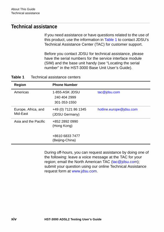
Technical assistanceIf you need assistance or have questions related to the use of this product, use the information in Table 1 to contact JDSU’s Technical Assistance Center (TAC) for customer support.
Before you contact JDSU for technical assistance, please have the serial numbers for the service interface module (SIM) and the base unit handy (see “Locating the serial number” in the HST-3000 Base Unit User’s Guide).
During off-hours, you can request assistance by doing one of the following: leave a voice message at the TAC for your region; email the North American TAC ([email protected]); submit your question using our online Technical Assistance request form at www.jdsu.com.
Table 1 Technical assistance centers
Region Phone Number
Americas 1-855-ASK JDSU
240 404 2999301-353-1550
Europe, Africa, and Mid-East
+49 (0) 7121 86 1345 (JDSU Germany)
Asia and the Pacific +852 2892 0990 (Hong Kong)
+8610 6833 7477 (Beijing-China)
About This GuideConventions
HST-3000 ADSL2 Testing User’s Guide xv
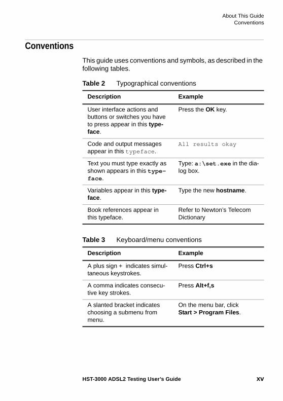
ConventionsThis guide uses conventions and symbols, as described in the following tables.
Table 2 Typographical conventions
Description Example
User interface actions and buttons or switches you have to press appear in this type-face .
Press the OK key.
Code and output messages appear in this typeface.
All results okay
Text you must type exactly as shown appears in this type-face.
Type: a:\set.exe in the dia-log box.
Variables appear in this type-face.
Type the new hostname.
Book references appear in this typeface.
Refer to Newton’s Telecom Dictionary
Table 3 Keyboard/menu conventions
Description Example
A plus sign + indicates simul-taneous keystrokes.
Press Ctrl+s
A comma indicates consecu-tive key strokes.
Press Alt+f,s
A slanted bracket indicates choosing a submenu from menu.
On the menu bar, click Start > Program Files .
About This GuideConventions
xvi HST-3000 ADSL2 Testing User’s Guide
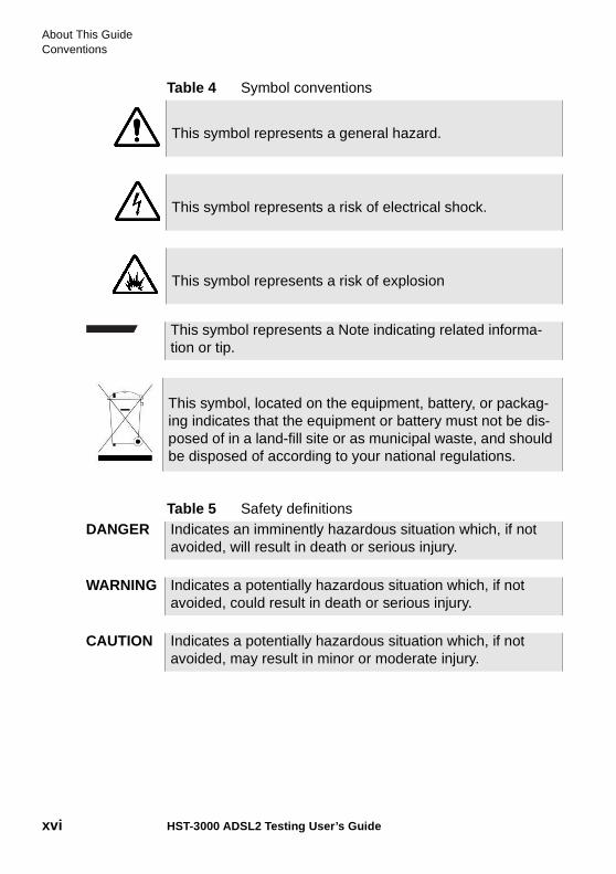
Table 4 Symbol conventions
Table 5 Safety definitions
This symbol represents a general hazard.
This symbol represents a risk of electrical shock.
This symbol represents a risk of explosion
This symbol represents a Note indicating related informa-tion or tip.
This symbol, located on the equipment, battery, or packag-ing indicates that the equipment or battery must not be dis-posed of in a land-fill site or as municipal waste, and should be disposed of according to your national regulations.
DANGER Indicates an imminently hazardous situation which, if not avoided, will result in death or serious injury.
WARNING Indicates a potentially hazardous situation which, if not avoided, could result in death or serious injury.
CAUTION Indicates a potentially hazardous situation which, if not avoided, may result in minor or moderate injury.
1
HST-3000 ADSL2 Testing User’s Guide 1
Chapter 1Getting Started
This chapter provides a general description of the HST-3000’s optional ADSL2 testing features. Topics discussed in this chapter include the following:
– “About ADSL2 testing” on page 2
– “Quick tour” on page 3
Chapter 1 Getting StartedAbout ADSL2 testing
2 HST-3000 ADSL2 Testing User’s Guide
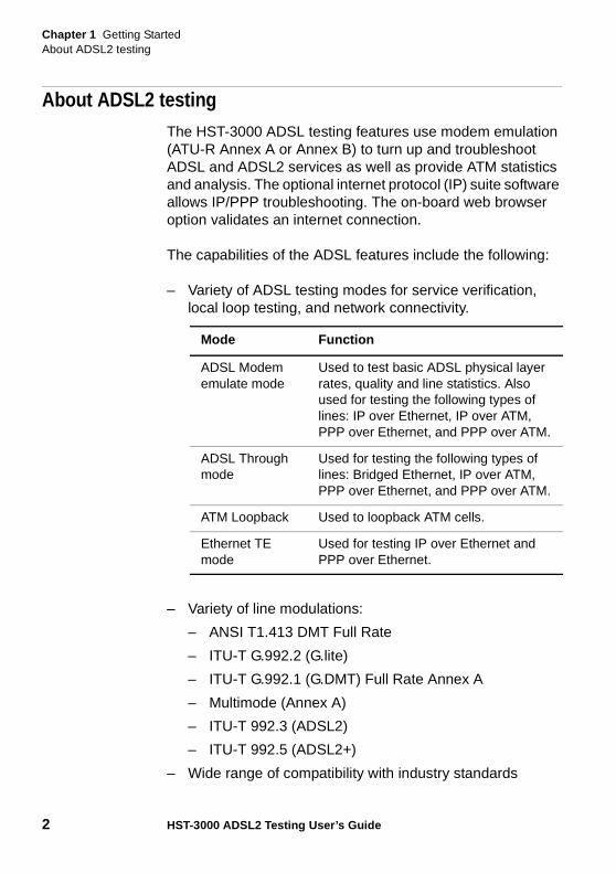
About ADSL2 testingThe HST-3000 ADSL testing features use modem emulation (ATU-R Annex A or Annex B) to turn up and troubleshoot ADSL and ADSL2 services as well as provide ATM statistics and analysis. The optional internet protocol (IP) suite software allows IP/PPP troubleshooting. The on-board web browser option validates an internet connection.
The capabilities of the ADSL features include the following:
– Variety of ADSL testing modes for service verification, local loop testing, and network connectivity.
– Variety of line modulations:
– ANSI T1.413 DMT Full Rate
– ITU-T G.992.2 (G.lite)
– ITU-T G.992.1 (G.DMT) Full Rate Annex A
– Multimode (Annex A)
– ITU-T 992.3 (ADSL2)
– ITU-T 992.5 (ADSL2+)
– Wide range of compatibility with industry standards
Mode Function
ADSL Modem emulate mode
Used to test basic ADSL physical layer rates, quality and line statistics. Also used for testing the following types of lines: IP over Ethernet, IP over ATM, PPP over Ethernet, and PPP over ATM.
ADSL Through mode
Used for testing the following types of lines: Bridged Ethernet, IP over ATM, PPP over Ethernet, and PPP over ATM.
ATM Loopback Used to loopback ATM cells.
Ethernet TE mode
Used for testing IP over Ethernet and PPP over Ethernet.
Chapter 1 Getting StartedQuick tour
HST-3000 ADSL2 Testing User’s Guide 3
– On-board web browser for validating the customer’s internet connection
– Trace route and FTP/HTTP throughput capability
– Customer premise equipment emulation to turn up and troubleshoot ADSL service, including Ethernet terminal equipment (TE)
– ATM F5 loopback capability
– ATM BERT capability
Quick tourThe following sections describe the HST’s LED status indica-tors and connector applicable to ADSL.
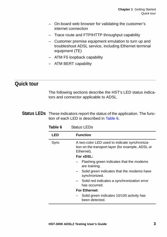
Status LEDs These indicators report the status of the application. The func-tion of each LED is described in Table 6.
Table 6 Status LEDs
LED Function
Sync A two-color LED used to indicate synchroniza-tion on the transport layer (for example, ADSL or Ethernet). For xDSL:– Flashing green indicates that the modems
are training. – Solid green indicates that the modems have
synchronized. – Solid red indicates a synchronization error
has occurred.For Ethernet:– Solid green indicates 10/100 activity has
been detected.
Chapter 1 Getting StartedQuick tour
4 HST-3000 ADSL2 Testing User’s Guide
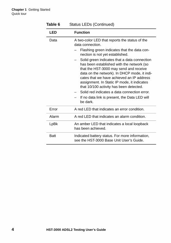
Data A two-color LED that reports the status of the data connection.– Flashing green indicates that the data con-
nection is not yet established. – Solid green indicates that a data connection
has been established with the network (so that the HST-3000 may send and receive data on the network). In DHCP mode, it indi-cates that we have achieved an IP address assignment. In Static IP mode, it indicates that 10/100 activity has been detected.
– Solid red indicates a data connection error.
– If no data link is present, the Data LED will be dark.
Error A red LED that indicates an error condition.
Alarm A red LED that indicates an alarm condition.
LpBk An amber LED that indicates a local loopback has been achieved.
Batt Indicated battery status. For more information, see the HST-3000 Base Unit User’s Guide.
Table 6 Status LEDs (Continued)
LED Function
Chapter 1 Getting StartedQuick tour
HST-3000 ADSL2 Testing User’s Guide 5
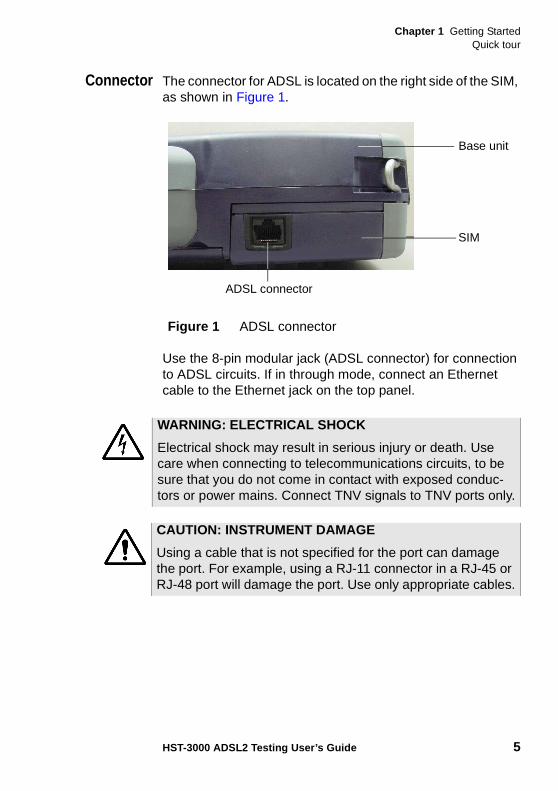
Connector The connector for ADSL is located on the right side of the SIM, as shown in Figure 1.
Use the 8-pin modular jack (ADSL connector) for connection to ADSL circuits. If in through mode, connect an Ethernet cable to the Ethernet jack on the top panel.
Figure 1 ADSL connector
SIM
Base unit
ADSL connector
WARNING: ELECTRICAL SHOCK
Electrical shock may result in serious injury or death. Use care when connecting to telecommunications circuits, to be sure that you do not come in contact with exposed conduc-tors or power mains. Connect TNV signals to TNV ports only.
CAUTION: INSTRUMENT DAMAGE
Using a cable that is not specified for the port can damage the port. For example, using a RJ-11 connector in a RJ-45 or RJ-48 port will damage the port. Use only appropriate cables.
Chapter 1 Getting StartedQuick tour
6 HST-3000 ADSL2 Testing User’s Guide
User interfacenavigation
You can use the Home and Config keys to cycle through the applications. The menus cycle in order, top to bottom as shown on the main application screen.
For example, if you are in the Modem Emulate application, pressing Home will move to the Data application, and then the VoIP application, and then IP Video.
The same methodology applies to the configuration menus. If you are viewing the General modem settings, pressing Config will move to the Data settings, and then VoIP General settings, and then the Video Settings.
Sealing currentterminator
The sealing current terminator, HST3000-SC, is an optional accessory available for DSL service. It is used when sealing current or wetting current must be terminated. Typically this occurs in an all-digital environment, but is not typical in DSL since the equipment (NT1 or telephone) provides termination.
The LED on the module indicates presence of sealing current. Place the module in-line, using the provided test cable.
The module is designed to terminate voltages under 80 volts, anything over 80V may make the module act erratic (LED flicker, go dim, etc.)
NOTE:
It is not recommended leaving the sealing current termina-tor on the line in the presence of a repeater because the module oscillates and could cause signal integrity issues effecting HST test results.
CAUTION: DAMAGE TO MODULE
Placing the sealing current terminator on a line with voltage over 150 volts may damage the unit.
Chapter 1 Getting StartedQuick tour
HST-3000 ADSL2 Testing User’s Guide 7
Updating themodem
software
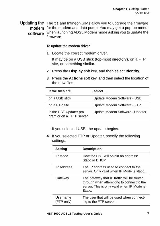
The TI and Infineon SIMs allow you to upgrade the firmware for the modem and data pump. You may get a pop-up menu when launching ADSL Modem mode asking you to update the firmware.
To update the modem driver
1 Locate the correct modem driver.
It may be on a USB stick (top-most directory), on a FTP site, or something similar.
2 Press the Display soft key, and then select Identity .
3 Press the Actions soft key, and then select the location of the new files.
If you selected USB, the update begins.
4 If you selected FTP or Updater, specify the following settings:
If the files are... select...
on a USB stick Update Modem Software - USB
on a FTP site Update Modem Software - FTP
in the HST Updater pro-gram or on a TFTP server
Update Modem Software - Updater
Setting Description
IP Mode How the HST will obtain an address: Static or DHCP
IP Address The IP address used to connect to the server. Only valid when IP Mode is static.
Gateway The gateway that IP traffic will be routed through when attempting to connect to the server. This is only valid when IP Mode is Static.
Username (FTP only)
The user that will be used when connect-ing to the FTP server.
Chapter 1 Getting StartedQuick tour
8 HST-3000 ADSL2 Testing User’s Guide
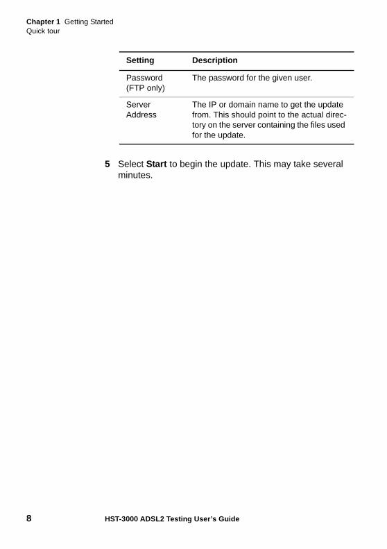
5 Select Start to begin the update. This may take several minutes.
Password (FTP only)
The password for the given user.
Server Address
The IP or domain name to get the update from. This should point to the actual direc-tory on the server containing the files used for the update.
Setting Description
2
HST-3000 ADSL2 Testing User’s Guide 9
Chapter 2ADSL2 Testing
This chapter provides task-based instructions for using the optional HST-3000 ADSL2 testing features. Topics discussed in this chapter include the following:
– “Accessing the ADSL2 testing feature” on page 10
– “Testing in modem emulate mode” on page 11
– “Testing in ADSL ATU-C mode” on page 21
– “Testing Data services” on page 24
– “Finding disturbers” on page 49
– “Saving graphical results” on page 53
Chapter 2 ADSL2 TestingAccessing the ADSL2 testing feature
10 HST-3000 ADSL2 Testing User’s Guide
Accessing the ADSL2 testing featureThe ADSL2 feature provides the following test modes:
– ATU-R Annex A Emulate
– ATU-R Annex A Through
The following procedure describes how to access the ADSL2 testing feature.
You can access Ethernet terminal equipment (TE) mode by pressing the Ethernet soft key (see “Ethernet TE Testing” in the HST-3000 Base Unit User’s Guide).
To access the ADSL testing feature
1 If you haven’t already done so, press the power key to turn on the HST-3000.
If the ADSL summary results screen appears after power up, auto launch is enabled and you are finished with this procedure.
Optional. To disable auto launch, do the following:
a Press the System key.
b Press the Instrument soft key.
c Select the Auto Launch menu item and change the setting to NONE.
The Auto Launch setting lets you specify an application to automatically load when the unit is powered up.
2 Press the Home navigation key.
3 Press the ADSL soft key.
Chapter 2 ADSL2 TestingTesting in modem emulate mode
HST-3000 ADSL2 Testing User’s Guide 11
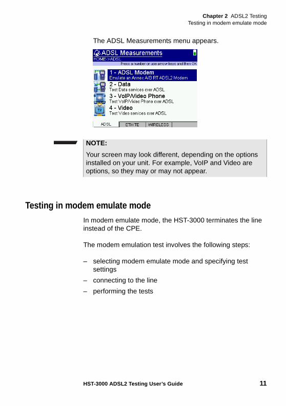
The ADSL Measurements menu appears.
Testing in modem emulate modeIn modem emulate mode, the HST-3000 terminates the line instead of the CPE.
The modem emulation test involves the following steps:
– selecting modem emulate mode and specifying test settings
– connecting to the line
– performing the tests
NOTE:
Your screen may look different, depending on the options installed on your unit. For example, VoIP and Video are options, so they may or may not appear.
Chapter 2 ADSL2 TestingTesting in modem emulate mode
12 HST-3000 ADSL2 Testing User’s Guide
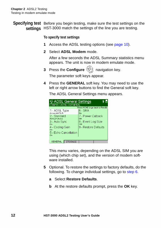
Specifying testsettings
Before you begin testing, make sure the test settings on the HST-3000 match the settings of the line you are testing.
To specify test settings
1 Access the ADSL testing options (see page 10).
2 Select ADSL Modem mode.
After a few seconds the ADSL Summary statistics menu appears. The unit is now in modem emulate mode.
3 Press the Configure navigation key.
The parameter soft keys appear.
4 Press the GENERAL soft key. You may need to use the left or right arrow buttons to find the General soft key.
The ADSL General Settings menu appears.
This menu varies, depending on the ADSL SIM you are using (which chip set), and the version of modem soft-ware installed.
5 Optional. To restore the settings to factory defaults, do the following. To change individual settings, go to step 6.
a Select Restore Defaults .
b At the restore defaults prompt, press the OK key.
Chapter 2 ADSL2 TestingTesting in modem emulate mode
HST-3000 ADSL2 Testing User’s Guide 13
The default modem settings are as follows:
– Standard — T1.413
– Transport — ATM (Infineon only)
– Auto Sync — On
– Coding Gain — On
– Echo Cancellation — Off
– SRA — On
– Power Cutback — Off
– Cable Type — 26 AWG
– Event Log Size — 100
6 Select ADSL Type and specify the type of ADSL line you are going to test.
Your selections may vary depending on the options that are configured on your unit. For example, you may have selections for Annex A and Annex B, or you may have selections for ATU-R and ATU-C, or you may not have an ADSL Type selection at all (if you have only Annex A ATU-R).
7 Select Transport and then specify ATM or PTM.
ADSL, by definition, transports data over Asynchronous Transfer Mode (ATM), while VDSL traditionally uses Packet Transfer Mode (PTM). If you have an Infineon SIM, ATM is the only selection; but if you have a TI SIM with the latest modem software or if you have a Broadcom SIM, which runs both ADSL and VDSL, both selections are available. If you have a Conexant SIM, the selection does not appear.
8 Select Auto Sync , and then select either On or Off .
9 This parameter specifies whether the HST-3000 will auto-matically attempt to re-sync with the DSLAM if the connection drops.
Chapter 2 ADSL2 TestingTesting in modem emulate mode
14 HST-3000 ADSL2 Testing User’s Guide
10 Select Standard , and then specify the ADSL line modula-tion standard in use:
– T1.413
– G.DMT
– G.Lite
– Multimode . Multimode will automatically pick T1.413, G.DMT, or G.Lite.
– ADSL2 (Auto) will revert to G.DMT if the line doesn’t support ADSL2.
– ADSL2+ (Auto) will revert to ADSL2 if the line doesn’t support ADSL2+ or revert to G.DMT if line doesn’t support ADSL2.
– ADSL2+ Auto (T1.413 off) is the same as “ADSL2+ (Auto)” except T1.413 is not available if reverting to ADSL. This selection only appears if using an Infineon SIM.
– ADSL2 forces ADSL2 only (if line doesn’t support ADSL2, the connection fails).
– ADSL2/2+ allows either ADSL2 or ADSL2+ (if line doesn’t support ADSL2/2+, the connection fails)
– ADSL2+ (Auto w/T1.413) is the same as “ADSL2+ (Auto)”, but will try T1.413 also. This selection only appears if using a Conexant SIM.
11 Select Annex and then specify the type of ADSL line you are going to test: Annex A, Annex B, Annex M, and Annex J. This selection is only available on Infineon SIMs with modem software version 5.1.4.0. (To verify your modem software version, go to the Identity results menu.)Select DSL Interface and then specify whether to use the RJ45 connector or Tip/Ring/Ground as the DSL interface.
Chapter 2 ADSL2 TestingTesting in modem emulate mode
HST-3000 ADSL2 Testing User’s Guide 15
This selection is only available on Infineon SIMs. To verify your SIM version, go to the System>Options/Revs/Copy-right menu and then select REVISIONS. Your part number should be one of the following:
21115525-001 SIM ASSY, xDSL/WB2, INFINEON
21115525-002 SIM ASSY, xDSL/DVOM, INFINEON
21115525-003 SIM ASSY, xDSL, INFINEON
12 Select Coding Gain and select either On or Off.
This parameter selects whether Coding Gain is included in the calculation of the Noise Margin result.
13 If the line modulation standard is G.Lite, the Fast Retrain option appears. Select Fast Retrain , and then select either On or Off .
This parameter specifies whether the HST-3000 attempts to reconnect at the same speed (ON) or fully initiate the line and retrain (OFF).
14 Select Echo Cancellation , and then select either On or Off .
Echo cancellation is a special ADSL mode in which UP and DOWN bands overlap to provide higher data rates. Select this only if you know it is required.
15 Select SRA, and then select either On or Off .
Seamless Rate Adaptation changes the data rate while in operation without any interruption to data service.
16 Select Power Cutback , and then select either Off or 1 - 12dB .
Power cutback allows you to reduce the local tx power. This can reduce the level of NEXT (near-end cross talk) as well as lowering the overall power consumption of the HST-3000.
17 Select Cable Type , and then choose either 26 AWG or GPLK 0.5mm as the type of cable.
This setting is used for the estimated loop length calcula-tion.
Chapter 2 ADSL2 TestingTesting in modem emulate mode
16 HST-3000 ADSL2 Testing User’s Guide
It only appears if both of the following conditions exist:
– you are using an ADSL2 SIM that contains the E.67.5.33 driver (found on the Identity results screen).
– you are using one of the following standards: T.413, G.DMT, G.lite, Multimode.
Thus, if you are using an ADSL SIM (not ADSL2), or you are using the ADSL2 or ADSL2+ standard, you will not see this item.
18 If you are using an Infineon SIM, select Max Rate and then specify whether the Downstream Max Rate is calcu-lated with framing overhead or without.
NOTE: Changing this setting will cause the modem to resync to apply the new setting.
19 If you aree using a TI SIM, select Max Rate S=1/2 and specify whether to include the S=1/2 calculation for the Max Rate. If enabled, the max down rate may be increased beyond 10M.
20 Optional. If you are using a TI SIM and wish to configure the modem’s data pump, select Datapump Config , specify Custom , and then enter a hexadecimal number between 0x00000000 and 0xFFFFFFFF. The Default setting sets the data pump value to 0 for all data pumps except the 6.00.06.03 data pump which is set to 0x2000. Select this only if you know it is required.
21 Select Event Log Size , and then specify the size of the event log. The size options are as follows: 100, 200, 300, 400, 500.
22 If you are using a Conexant SIM and wish to change the modem driver, use Select Driver to select a driver.
The general modem settings are specified.
Connecting tothe line
After specifying the test settings, you can connect to the line.
Chapter 2 ADSL2 TestingTesting in modem emulate mode
HST-3000 ADSL2 Testing User’s Guide 17
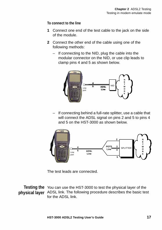
To connect to the line
1 Connect one end of the test cable to the jack on the side of the module.
2 Connect the other end of the cable using one of the following methods:
– If connecting to the NID, plug the cable into the modular connector on the NID, or use clip leads to clamp pins 4 and 5 as shown below.
– If connecting behind a full-rate splitter, use a cable that will connect the ADSL signal on pins 2 and 5 to pins 4 and 5 on the HST-3000 as shown below.
The test leads are connected.
Testing thephysical layer
You can use the HST-3000 to test the physical layer of the ADSL link. The following procedure describes the basic test for the ADSL link.
NETWORK
4
5 ADSLLine
NIDLine port
NETWORK
4
5 ADSLLine
NIDLine port
NETWORK
3
4
2
ADSLLine
POTSLine
4
5Line port
SPLITTER
5
Chapter 2 ADSL2 TestingTesting in modem emulate mode
18 HST-3000 ADSL2 Testing User’s Guide
To perform a basic ADSL link test
– Connect to the line and allow the unit to train on the line.
If the unit achieves sync at the desired data rates, noise margins, and attenuation, the ADSL link is good.
Testing linequality
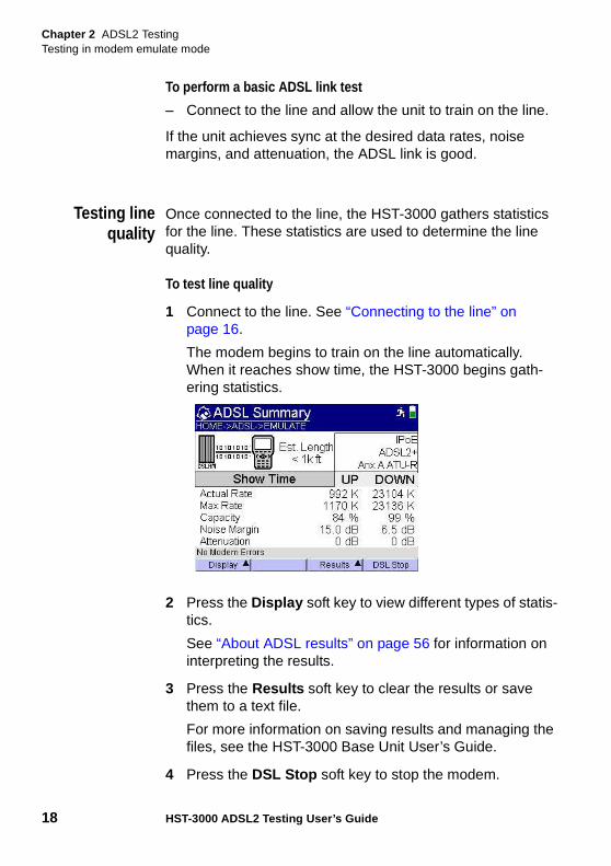
Once connected to the line, the HST-3000 gathers statistics for the line. These statistics are used to determine the line quality.
To test line quality
1 Connect to the line. See “Connecting to the line” on page 16.
The modem begins to train on the line automatically. When it reaches show time, the HST-3000 begins gath-ering statistics.
2 Press the Display soft key to view different types of statis-tics.
See “About ADSL results” on page 56 for information on interpreting the results.
3 Press the Results soft key to clear the results or save them to a text file.
For more information on saving results and managing the files, see the HST-3000 Base Unit User’s Guide.
4 Press the DSL Stop soft key to stop the modem.
Chapter 2 ADSL2 TestingTesting in modem emulate mode
HST-3000 ADSL2 Testing User’s Guide 19
All DSL results will remain in view until the modem is started again or another test is selected.
See “About ADSL results” on page 56 for information on interpreting the results.
Testing line quality is complete.
Running aDr. DSL test
The HST-3000 includes Aware, Inc.’s Dr. DSL diagnostics tool. This is an optional capability available on the Infineon SIMs, in Annex A, Annex B, and Annex M mode.
For additional information about HST-3000 options, SIMs, and services, contact your local JDSU representative for details. The regional sales offices are listed on the back cover of this guide or contact JDSU through the company web site, www.jdsu.com.
The Dr. DSL function includes five parts, and you can order one or all of the parts.
– The core function includes tests for loop length, insertion loss, bridge tap detection, and data rate expert (provide the ideal maximum data rate achievable on a clean line).
– Dr. DSL OSP Expert – In addition to the core features, this function includes bridge tap test (detect and provide length), AM radio test, crosstalk analysis, spectral anal-ysis, noise and attenuation test, and OSP expert (diag-nostic analysis when connected to ADSL2+ CPE).
– Dr. DSL In-home Expert – In addition to the core features, this function includes a micro-filter detection test, which identifies missing micro-filters.
– Dr. DSL Rate Reduction Expert – In addition to the core features, this function identifies and predicts the amount of rate loss that is occurring due to the interference. It analyzes crosstalk, AM interferers, and bridge taps.
– Dr. DSL 30 MHz Spectral – In addition to the core features, this function includes a 30 MHz AM radio test, 30 MHz crosstalk analysis, and 30 MHz spectral analysis.
Chapter 2 ADSL2 TestingTesting in modem emulate mode
20 HST-3000 ADSL2 Testing User’s Guide
To run a Dr. DSL test
1 Connect to the line. See “Connecting to the line” on page 16.
The modem begins to train on the line automatically. When it reaches show time, the HST-3000 begins gath-ering statistics.
2 Press the Display soft key and then select Dr. DSL .
The ADSL Dr. DSL screen appears and the background test begins.
3 To run a different test,, press the Actions soft key and then select one of the following:
– Run Microfilter Test - determines whether a micro-filter is present. (This test is not available in ATU-C mode.)
– Run 30 MHz Spectral - runs only the 30 Mhz Spectral test.
This test can be run in the following ways:. from CPE with the far end CO connected. from CPE with the far end open. from the CO with the CPE openif run in another way, the results may not be as expected.
Your selections may include one or all of these selections, depending on which options are installed in your unit.
The test stops automatically when done.
4 Press the Results soft key to view the graph results or save them to a text file.
For more information on saving results and managing the files, see the HST-3000 Base Unit User’s Guide.
See “Dr. DSL results” on page 64 for information on inter-preting the results.
You have completed the test.
Chapter 2 ADSL2 TestingTesting in ADSL ATU-C mode
HST-3000 ADSL2 Testing User’s Guide 21
Testing in ADSL ATU-C modeIf you have an Infineon SIM, the HST-3000 can emulate an ADSL ATU-C to help sectionalize troubles.
Using this mode involves the following steps:
– selecting ATU-C as the ADSL Type and specifying test settings
– connecting to the line
– performing the tests
Specifying testsettings
Before you begin testing, make sure the test settings on the HST-3000 match the settings of the line you are testing.
Specifying generalmodem settings
The procedure in this section describes how to specify the general modem settings. These settings vary depending on whether you have an Annex A or Annex B modem. You can restore the default settings, or you can specify the individual settings.
The default modem settings for Annex A are as follows:
– DSL Type — ATU-R
– Transport — ATM (Infineon only)
– Auto Sync — On
– Standard — ADSL2+ Auto
– Annex — Annex A
To restore default modem settings
1 Press the Configure navigation key.
NOTE:
Data testing is not available in ATU-C mode.
Chapter 2 ADSL2 TestingTesting in ADSL ATU-C mode
22 HST-3000 ADSL2 Testing User’s Guide
The parameter soft keys appear.
2 Press the GENERAL soft key. You may need to use the left or right arrow buttons to find the General soft key.
The General Settings menu appears
3 Select Restore Defaults .
4 At the restore defaults prompt, press the OK.
The default modem settings are restored.
The following procedure describes how to specify individual modem settings.
To specify general modem settings
1 Press the GENERAL soft key. You may need to use the left or right arrow button to find the General soft key.
The ADSL General Settings menu appears.
2 Select DSL Type , and then select ATU-C.
3 Select Auto Sync , and then select either On or Off .
This parameter specifies whether the HST-3000 will auto-matically attempt to re-sync with the modem if the connection drops.
4 Select Standard , and then specify ADSL2+ or G.DMT.
5 Select Annex , and then specify Annex A, B, or M.(annex J is only available in ATU-R)
6 Select Event Log Size , and then specify the size of the event log. The size options are as follows: 100, 200, 300, 400, 500.
The general modem settings are specified.
Connecting tothe line
After specifying the test settings, you can connect to the line.
Chapter 2 ADSL2 TestingTesting in ADSL ATU-C mode
HST-3000 ADSL2 Testing User’s Guide 23
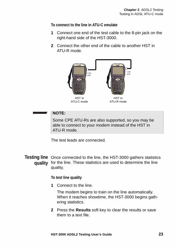
To connect to the line in ATU-C emulate
1 Connect one end of the test cable to the 8-pin jack on the right-hand side of the HST-3000.
2 Connect the other end of the cable to another HST in ATU-R mode.
The test leads are connected.
Testing linequality
Once connected to the line, the HST-3000 gathers statistics for the line. These statistics are used to determine the line quality.
To test line quality
1 Connect to the line.
The modem begins to train on the line automatically. When it reaches showtime, the HST-3000 begins gath-ering statistics.
2 Press the Results soft key to clear the results or save them to a text file.
HST inATU-C mode
HST inATU-R mode
Line port
Line port
NOTE:
Some CPE ATU-Rs are also supported, so you may be able to connect to your modem instead of the HST in ATU-R mode.
Chapter 2 ADSL2 TestingTesting Data services
24 HST-3000 ADSL2 Testing User’s Guide
For more information on saving results and managing the files, see the HST-3000 Base Unit User’s Guide.
3 Press the Display soft key to view different types of statis-tics.
See Chapter 3 “Interpreting Test Results” to learn what your results mean.
Testing line quality is complete.
Testing Data servicesIn through mode, the HST-3000 replaces the customer’s ADSL modem to help sectionalize troubles. Depending on the ADSL test option you purchased, you can perform Annex A and Annex B through mode testing.
The data services test involves the following steps:
– specifying the emulation type
– specifying test settings
– connecting to the line
– performing the tests
Specifying theemulation type
The first step is to specify the emulation type.
To specify the emulation type
1 From the main ADSL Measurements menu (see page 10), select Data.
After a few seconds, the ADSL Summary statistics menu appears.
NOTE:
Data testing is not available in ATU-C mode.
Chapter 2 ADSL2 TestingTesting Data services
HST-3000 ADSL2 Testing User’s Guide 25
2 Press the Configure navigation key.
The parameter soft keys appear.
3 Select the DATA soft key.
4 Select Emulation Type and choose an emulation.
5 This setting specifies the data emulation: whether to Terminate the line to analyze the data or pass the data Through after analyzing it.
Specifying testsettings
Before you begin testing, make sure the settings on the HST-3000 match the settings of the line you are testing. The following settings can be specified on the HST:
– Data settings (see “Specifying data settings” on page 26)
– PPP settings (see “Specifying PPP settings” on page 34)
– LAN settings (see “Specifying LAN settings” on page 28)
– WAN settings (see “Specifying WAN settings” on page 30)
– Ping settings (see “Specifying ping settings” on page 35)
– Trace route settings (see “Specifying trace route settings” on page 36)
– FTP/HTTP settings (see “Specifying FTP/HTTP settings” on page 37)
– ATM BERT settings (see “Specifying ATM BERT settings” on page 39)
CAUTION: FAULTY RESULTS
Changing these settings during a test may cause errors in the test. Only change them before you begin a test.
Chapter 2 ADSL2 TestingTesting Data services
26 HST-3000 ADSL2 Testing User’s Guide
Specifying datasettings
To use ping, trace route, FTP/HTTP, or the web browser, the data configuration must be set correctly. The VPI and VCI settings must match the customer-facing settings for the ADSL ports on the DSLAM.
Be sure to check these settings before you proceed with test-ing. Check the trouble ticket or call your help desk for assis-tance.
The following procedure describes how to specify the data settings.
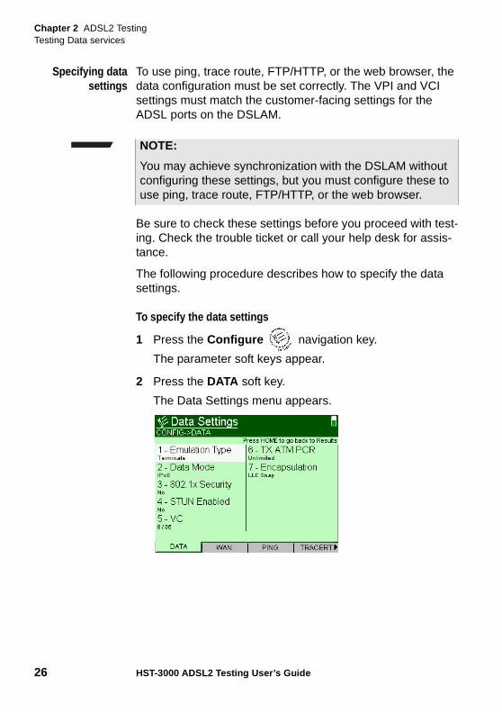
To specify the data settings
1 Press the Configure navigation key.
The parameter soft keys appear.
2 Press the DATA soft key.
The Data Settings menu appears.
NOTE:
You may achieve synchronization with the DSLAM without configuring these settings, but you must configure these to use ping, trace route, FTP/HTTP, or the web browser.
Chapter 2 ADSL2 TestingTesting Data services
HST-3000 ADSL2 Testing User’s Guide 27
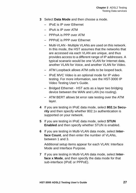
3 Select Data Mode and then choose a mode.
– IPoE is IP over Ethernet
– IPoA is IP over ATM
– PPPoA is PPP over ATM
– PPPoE is PPP over Ethernet
– Multi-VLAN - Multiple VLANs are used on this network. In this mode, the HST assumes that the networks that are accessed via each VLAN are unique, and thus provides access to a different range of IP addresses. A typical scanario would be one VLAN for Internet data, another VLAN for Voice, and another VLAN for Video.
– ATM Loopback allows ATM cells to be looped back.
– IPoE MVC Video is an optional mode for IP video testing. For more information, see the HST-3000 IP Video Testing User’s Guide.
– Bridged Ethernet - HST acts as a layer two bridging device between the WAN and LAN (no routing).
– ATM BERT allows bit error rate testing over the ATM layer.
4 If you are testing in IPoE data mode, select 802.1x Secu-rity and then specify whether 802.1x authentication is supported on your network.
5 If you are testing in IPoE data mode, select STUN Enabled and then specify whether STUN is enabled.
6 If you are testing in Multi-VLAN data mode, select Inter-face Count , and then enter the number of VLANs, between 1 and 3.
Additional setup items appear for each VLAN: Interface Mode and Interface Purpose.
7 If you are testing in Multi-VLAN data mode, select Inter-face x Mode , and then specify the data mode for that sub-interface (IPoE or PPPoE).
Chapter 2 ADSL2 TestingTesting Data services
28 HST-3000 ADSL2 Testing User’s Guide
8 If you are testing in Multi-VLAN data mode, select Inter-face x Purpose , and then specify the purpose for that sub-interface (Internet, Video, or Voice).
9 Repeat steps 7 and 8 for any remaining interfaces.
10 Select VC, and then enter the virtual path indicator (VPI) and virtual channel indicator (VCI) for the virtual channel (VC) under test.
11 If you selected IPoE, IPoA, PPPoA, PPPoE, MVC Video, or Bridged Ethernet Data Mode, select TX ATM PCR and enter the transmit peak cell rate.
– Unlimited transmits the maximum cell rate allowed on the circuit.
– User Specified allows you to enter a value from 2 to 50000 cells per second.
12 If you selected IPoE, IPoA, PPPoA, or PPPoE Data Mode, select Encapsulation , and then specify the appro-priate setting.
13 If you selected ATM Loopback Data Mode, select Loop-back Mode and specify whether to loop ALL cells or only TTC cells.
The data settings are specified.
Specifying LANsettings
The following procedure describes how to specify the LAN settings. The LAN settings are only available in Through mode (when the Data Emulation Type is set to Through).
NOTE:
If the rate entered is not attainable, the HST will round down to the next attainable rate.
NOTE:
Depending on previous settings, you may have to navigate to item 10 on the menu, and then press the down arrow to find this selection.
Chapter 2 ADSL2 TestingTesting Data services
HST-3000 ADSL2 Testing User’s Guide 29
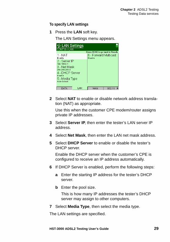
To specify LAN settings
1 Press the LAN soft key.
The LAN Settings menu appears.
2 Select NAT to enable or disable network address transla-tion (NAT) as appropriate.
Use this when the customer CPE modem/router assigns private IP addresses.
3 Select Server IP, then enter the tester’s LAN server IP address.
4 Select Net Mask , then enter the LAN net mask address.
5 Select DHCP Server to enable or disable the tester’s DHCP server.
Enable the DHCP server when the customer’s CPE is configured to receive an IP address automatically.
6 If DHCP Server is enabled, perform the following steps:
a Enter the starting IP address for the tester’s DHCP server.
b Enter the pool size.
This is how many IP addresses the tester’s DHCP server may assign to other computers.
7 Select Media Type , then select the media type.
The LAN settings are specified.
Chapter 2 ADSL2 TestingTesting Data services
30 HST-3000 ADSL2 Testing User’s Guide
Specifying WANsettings
The following procedure describes how to specify the wide area network (WAN) settings. The WAN interface is the DSL connection to tip and ring. The WAN settings are only avail-able when the Emulation Type is set to Through.
The WAN Settings menu appears if you are using IPoE or Multi VLAN data mode. For Multi VLAN data mode, you may have more than one WAN screen (for example, WAN2, WAN3).
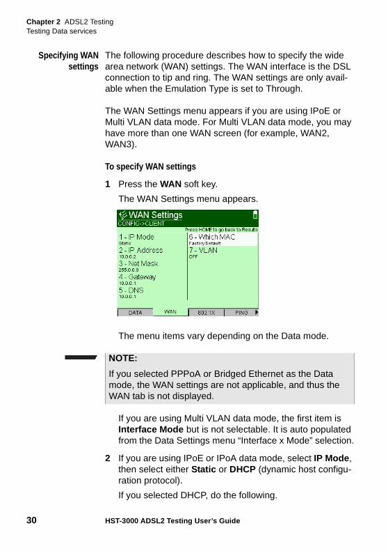
To specify WAN settings
1 Press the WAN soft key.
The WAN Settings menu appears.
The menu items vary depending on the Data mode.
If you are using Multi VLAN data mode, the first item is Interface Mode but is not selectable. It is auto populated from the Data Settings menu “Interface x Mode” selection.
2 If you are using IPoE or IPoA data mode, select IP Mode , then select either Static or DHCP (dynamic host configu-ration protocol).
If you selected DHCP, do the following.
NOTE:
If you selected PPPoA or Bridged Ethernet as the Data mode, the WAN settings are not applicable, and thus the WAN tab is not displayed.
Chapter 2 ADSL2 TestingTesting Data services
HST-3000 ADSL2 Testing User’s Guide 31
a Select Use Vendor ID and specify whether the vendor ID is used.
If you selected Yes, enter the Vendor ID .
b Go to step 3.
If you selected Static, do the following.
a Select IP Address , then enter the IP address.
b Select Net Mask , then enter the net mask address.
c Select Gateway , then enter the gateway address.
d Select DNS, then enter the address of the DNS server.
If you are using IPoA data mode, proceed to step 4.
3 If you are using PPPoE or IPoE data mode, do the following.
a Select Which MAC , then specify either User Defined or Factory Default .
b If the Which MAC parameter is set to User Defined, enter the appropriate address.
c Select VLAN , then set it to On or Off .
The Virtual LAN (VLAN) setting is only necessary if a VLAN is used to segregate video data flows from other data flows.
If VLAN is on, specify the VLAN ID and VLAN Priority .
4 Press the Home navigation key to return to the Data Summary screen.
The WAN settings are specified.
NOTE:
If you are using Multi VLAN data mode and you specify the same settings for different VLANs, a “VLAN CONFLICT” error will be displayed.
Chapter 2 ADSL2 TestingTesting Data services
32 HST-3000 ADSL2 Testing User’s Guide
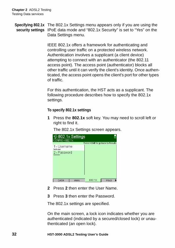
Specifying 802.1xsecurity settings
The 802.1x Settings menu appears only if you are using the IPoE data mode and “802.1x Security” is set to “Yes” on the Data Settings menu.
IEEE 802.1x offers a framework for authenticating and controlling user traffic on a protected wireless network. Authentication involves a supplicant (a client device) attempting to connect with an authenticator (the 802.11 access point). The access point (authenticator) blocks all other traffic until it can verify the client's identity. Once authen-ticated, the access point opens the client's port for other types of traffic.
For this authentication, the HST acts as a supplicant. The following procedure describes how to specify the 802.1x settings.
To specify 802.1x settings
1 Press the 802.1x soft key. You may need to scroll left or right to find it.
The 802.1x Settings screen appears.
2 Press 2 then enter the User Name.
3 Press 3 then enter the Password.
The 802.1x settings are specified.
On the main screen, a lock icon indicates whether you are authenticated (indicated by a secured/closed lock) or unau-thenticated (an open lock).
Chapter 2 ADSL2 TestingTesting Data services
HST-3000 ADSL2 Testing User’s Guide 33
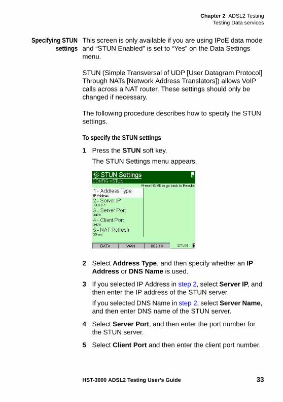
Specifying STUNsettings
This screen is only available if you are using IPoE data mode and “STUN Enabled” is set to “Yes” on the Data Settings menu.
STUN (Simple Transversal of UDP [User Datagram Protocol] Through NATs [Network Address Translators]) allows VoIP calls across a NAT router. These settings should only be changed if necessary.
The following procedure describes how to specify the STUN settings.
To specify the STUN settings
1 Press the STUN soft key.
The STUN Settings menu appears.
2 Select Address Type , and then specify whether an IP Address or DNS Name is used.
3 If you selected IP Address in step 2, select Server IP, and then enter the IP address of the STUN server.
If you selected DNS Name in step 2, select Server Name , and then enter DNS name of the STUN server.
4 Select Server Port , and then enter the port number for the STUN server.
5 Select Client Port and then enter the client port number.
Chapter 2 ADSL2 TestingTesting Data services
34 HST-3000 ADSL2 Testing User’s Guide
6 Select NAT Refresh and then specify the NAT refresh rate. This is the number of seconds between messages to the STUN server to keep the NAT mapping alive.
The STUN settings are specified.
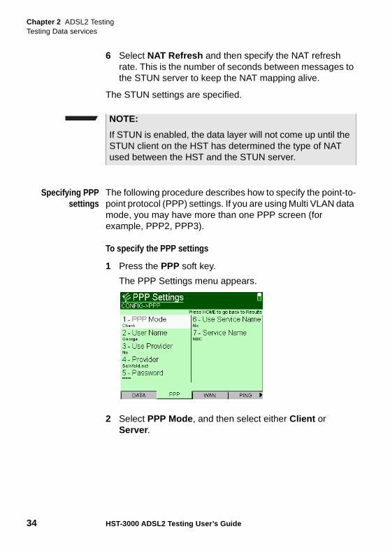
Specifying PPPsettings
The following procedure describes how to specify the point-to-point protocol (PPP) settings. If you are using Multi VLAN data mode, you may have more than one PPP screen (for example, PPP2, PPP3).
To specify the PPP settings
1 Press the PPP soft key.
The PPP Settings menu appears.
2 Select PPP Mode , and then select either Client or Server .
NOTE:
If STUN is enabled, the data layer will not come up until the STUN client on the HST has determined the type of NAT used between the HST and the STUN server.
Chapter 2 ADSL2 TestingTesting Data services
HST-3000 ADSL2 Testing User’s Guide 35
Client is normally used. Use Server only when you have an ATU-C. This feature allows a remote ATU-R to estab-lish a PPP session with the HST-3000.
If you are using the Multi VLAN data mode, this selection is found only on the PPP1 Settings page.
3 Select User Name , and then enter a valid user name.
This must be a valid user account with an ISP.
4 Select Use Provider , and then select either Yes or No.
This option indicates whether to append the user name with the service provider domain name (for example, earthlink.net). Select Yes only if user names for the ISP must include the domain name as part of the user name. This setting automatically appends the @ sign for you.
5 Select Provider , and then enter the provider name.
This is required if you selected Yes for “Use Provider.”
6 Select Password , and then enter the user password.
This must be a valid password that matches the user name above. Passwords are often case-sensitive.
7 Select Use Service Name .
8 If you selected “Yes” for Use Service Name, enter the Service Name .
The PPP settings are specified.
Specifying pingsettings
The following procedure describes how to specify the ping settings.
To specify the ping settings
1 Press the PING soft key.
NOTE:
If you selected “Server” as the PPP mode, connect only to other devices with the same service name.
Chapter 2 ADSL2 TestingTesting Data services
36 HST-3000 ADSL2 Testing User’s Guide
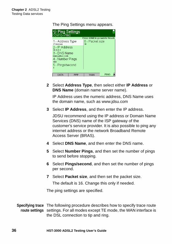
The Ping Settings menu appears.
2 Select Address Type , then select either IP Address or DNS Name (domain name server name).
IP Address uses the numeric address, DNS Name uses the domain name, such as www.jdsu.com
3 Select IP Address , and then enter the IP address.
JDSU recommend using the IP address or Domain Name Services (DNS) name of the ISP gateway of the customer's service provider. It is also possible to ping any internet address or the network Broadband Remote Access Server (BRAS).
4 Select DNS Name, and then enter the DNS name.
5 Select Number Pings , and then set the number of pings to send before stopping.
6 Select Pings/second , and then set the number of pings per second.
7 Select Packet size , and then set the packet size.
The default is 16. Change this only if needed.
The ping settings are specified.
Specifying traceroute settings
The following procedure describes how to specify trace route settings. For all modes except TE mode, the WAN interface is the DSL connection to tip and ring.
Chapter 2 ADSL2 TestingTesting Data services
HST-3000 ADSL2 Testing User’s Guide 37
To specify trace route settings
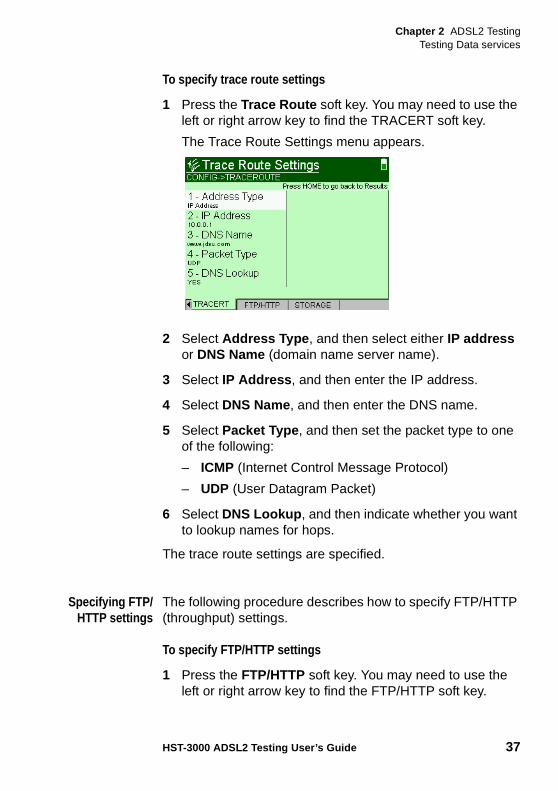
1 Press the Trace Route soft key. You may need to use the left or right arrow key to find the TRACERT soft key.
The Trace Route Settings menu appears.
2 Select Address Type , and then select either IP address or DNS Name (domain name server name).
3 Select IP Address , and then enter the IP address.
4 Select DNS Name, and then enter the DNS name.
5 Select Packet Type , and then set the packet type to one of the following:
– ICMP (Internet Control Message Protocol)
– UDP (User Datagram Packet)
6 Select DNS Lookup , and then indicate whether you want to lookup names for hops.
The trace route settings are specified.
Specifying FTP/HTTP settings
The following procedure describes how to specify FTP/HTTP (throughput) settings.
To specify FTP/HTTP settings
1 Press the FTP/HTTP soft key. You may need to use the left or right arrow key to find the FTP/HTTP soft key.
Chapter 2 ADSL2 TestingTesting Data services
38 HST-3000 ADSL2 Testing User’s Guide
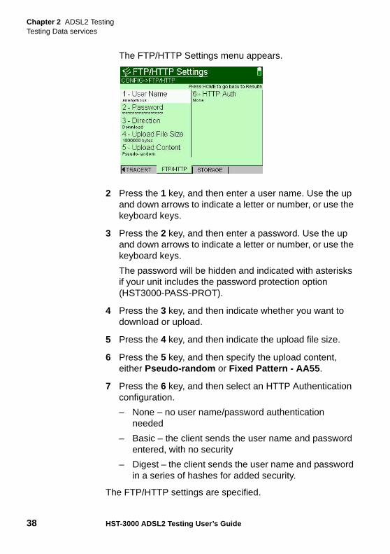
The FTP/HTTP Settings menu appears.
2 Press the 1 key, and then enter a user name. Use the up and down arrows to indicate a letter or number, or use the keyboard keys.
3 Press the 2 key, and then enter a password. Use the up and down arrows to indicate a letter or number, or use the keyboard keys.
The password will be hidden and indicated with asterisks if your unit includes the password protection option (HST3000-PASS-PROT).
4 Press the 3 key, and then indicate whether you want to download or upload.
5 Press the 4 key, and then indicate the upload file size.
6 Press the 5 key, and then specify the upload content, either Pseudo-random or Fixed Pattern - AA55 .
7 Press the 6 key, and then select an HTTP Authentication configuration.
– None – no user name/password authentication needed
– Basic – the client sends the user name and password entered, with no security
– Digest – the client sends the user name and password in a series of hashes for added security.
The FTP/HTTP settings are specified.
Chapter 2 ADSL2 TestingTesting Data services
HST-3000 ADSL2 Testing User’s Guide 39
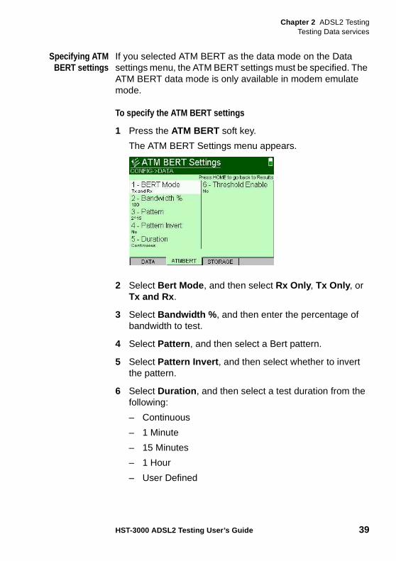
Specifying ATMBERT settings
If you selected ATM BERT as the data mode on the Data settings menu, the ATM BERT settings must be specified. The ATM BERT data mode is only available in modem emulate mode.
To specify the ATM BERT settings
1 Press the ATM BERT soft key.
The ATM BERT Settings menu appears.
2 Select Bert Mode , and then select Rx Only , Tx Only , or Tx and Rx .
3 Select Bandwidth % , and then enter the percentage of bandwidth to test.
4 Select Pattern , and then select a Bert pattern.
5 Select Pattern Invert , and then select whether to invert the pattern.
6 Select Duration , and then select a test duration from the following:
– Continuous
– 1 Minute
– 15 Minutes
– 1 Hour
– User Defined
Chapter 2 ADSL2 TestingTesting Data services
40 HST-3000 ADSL2 Testing User’s Guide
7 If you selected a User Defined Duration, select Custom Duration , and enter the number of minutes for the test duration.
8 Select Threshold Enable , and then indicate whether a threshold is enabled.
9 If Threshold Enable is Enabled, select Threshold , and then enter the threshold.
The ATM BERT settings are specified.
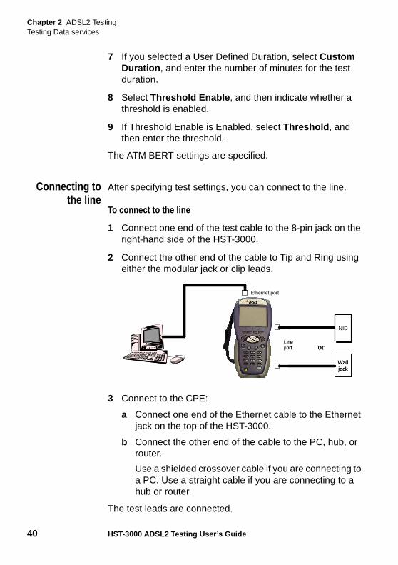
Connecting tothe line
After specifying test settings, you can connect to the line.
To connect to the line
1 Connect one end of the test cable to the 8-pin jack on the right-hand side of the HST-3000.
2 Connect the other end of the cable to Tip and Ring using either the modular jack or clip leads.
3 Connect to the CPE:
a Connect one end of the Ethernet cable to the Ethernet jack on the top of the HST-3000.
b Connect the other end of the cable to the PC, hub, or router.
Use a shielded crossover cable if you are connecting to a PC. Use a straight cable if you are connecting to a hub or router.
The test leads are connected.
Walljack
orLine port
Ethernet port
NID
Walljack
orLine port
Ethernet port
NID
Chapter 2 ADSL2 TestingTesting Data services
HST-3000 ADSL2 Testing User’s Guide 41
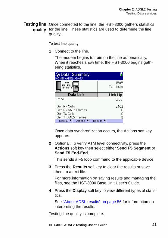
Testing linequality
Once connected to the line, the HST-3000 gathers statistics for the line. These statistics are used to determine the line quality.
To test line quality
1 Connect to the line.
The modem begins to train on the line automatically. When it reaches show time, the HST-3000 begins gath-ering statistics.
Once data synchronization occurs, the Actions soft key appears.
2 Optional. To verify ATM level connectivity, press the Actions soft key then select either Send F5 Segment or Send F5 End-End .
This sends a F5 loop command to the applicable device.
3 Press the Results soft key to clear the results or save them to a text file.
For more information on saving results and managing the files, see the HST-3000 Base Unit User’s Guide.
4 Press the Display soft key to view different types of statis-tics.
See “About ADSL results” on page 56 for information on interpreting the results.
Testing line quality is complete.
Chapter 2 ADSL2 TestingTesting Data services
42 HST-3000 ADSL2 Testing User’s Guide
Performing aping test
The ping test sends a ping packet through the modem to an IP address or DNS name (could be a network switch or web address) to test for connectivity.
The ping feature is available when the data mode is set to one of the following:
– IP over Ethernet (IPoE)
– IP over ATM (IPoA)
The following procedure describes how to perform a ping test.
To perform a ping test
1 Locate the Actions soft key.
If you do not see the Actions soft key, do the following:
a Check the Data LED.
The Data LED must be green in order to use the Actions softkey. If the Data LED is red, the network connection is not properly established.
b Press the Configure navigation key and make sure all test settings are correct for the circuit.
c Press the Home navigation key.
d Press the Display soft key, and then select Data - IP. See if there are any error messages.
e Locate the Actions soft key.
2 Press the Actions soft key.
NOTE:
You can also check connectivity using the web browser. See “Web browser” in the base manual for more informa-tion.
Chapter 2 ADSL2 TestingTesting Data services
HST-3000 ADSL2 Testing User’s Guide 43
3 Select a ping method:
– Ping Once sends a single ping to the network.
– Start Ping consecutively sends multiple pings to the network, up to the number of pings configured.
4 Press the Results soft key to clear the results or save them to a text file.
For more information on saving results and managing the files, see the HST-3000 Base Unit User’s Guide.
The ping test is complete.
Releasing IPaddresses
The HST allows you to release allocated IP addresses, so it can be used by other equipment. The IP release feature is available when the data mode is set to one of the following:
– IP over Ethernet (IPoE)
– PPP over Ethernet (PPPoE)
– PPP over ATM (PPPoA)
For instructions specifying the data mode, see “Specifying data settings” on page 26.
The following procedure describes how to release IP addresses.
To release IP addresses
1 Press the Home navigation key.
2 Connect the HST to the line. See “Connecting to the line” on page 40.
3 Press the Display soft key.
4 Press the 4 key to select IP Results.
The IP results window appears.
Chapter 2 ADSL2 TestingTesting Data services
44 HST-3000 ADSL2 Testing User’s Guide
5 Press the Actions soft key.
6 Select either Log-Off or IP-Release .
The Log-Off and IP-Release options are only available when you viewing the IP results window.
The IP address is now available for use in other applica-tions.
Throughputtesting
Using the FTP/HTTP throughput feature, you can perform a file transfer to test the throughput of the circuit.
To test throughput
1 Specify the FTP/HTTP settings (see “Specifying FTP/HTTP settings” on page 37).
2 Navigate to the FTP/HTTP results screen.
3 Press the Actions soft key.
4 Select FTP/HTTP and then Enter Address .
5 Enter the address using the keypad, including the prefix (ftp: or http: or, if applicable, https:) and the filename.
For example, ftp://10.0.0.1/name
6 Press OK to begin the file transfer.
The throughput results appear on the screen.
See “FTP/HTTP results” on page 76 for information on inter-preting the results.
ATM BERTtesting
The HST-3000 allows testing of the ATM layer using a bit error rate test (BERT). The following procedure describes how to perform an ATM BERT.
To perform an ATM BERT test
1 Verify that ATM BERT is selected as the Data Mode. See “Specifying data settings” on page 26.
Chapter 2 ADSL2 TestingTesting Data services
HST-3000 ADSL2 Testing User’s Guide 45
2 Press the Home navigation key.
3 Connect the HST to the line. See “Connecting to the line” on page 40.
After data synchronization occurs, the Actions soft key appears.
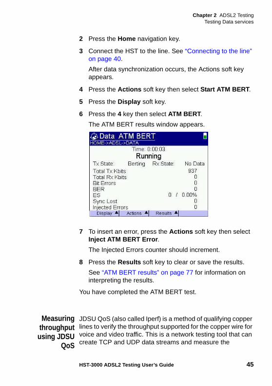
4 Press the Actions soft key then select Start ATM BERT .
5 Press the Display soft key.
6 Press the 4 key then select ATM BERT.
The ATM BERT results window appears.
7 To insert an error, press the Actions soft key then select Inject ATM BERT Error .
The Injected Errors counter should increment.
8 Press the Results soft key to clear or save the results.
See “ATM BERT results” on page 77 for information on interpreting the results.
You have completed the ATM BERT test.
Measuringthroughput
using JDSUQoS
JDSU QoS (also called Iperf) is a method of qualifying copper lines to verify the throughput supported for the copper wire for voice and video traffic. This is a network testing tool that can create TCP and UDP data streams and measure the
Chapter 2 ADSL2 TestingTesting Data services
46 HST-3000 ADSL2 Testing User’s Guide
throughput of the network carrying them. It allows the user to set various parameters in order to tune the test for the service that they are investigating. For example, to test video the user shall be able to set the transmission type to UDP and set the packet size to 1400 or whatever is appropriate for their network. The test statistics help determine if the service being deployed can be supported on the network. This test operates over a PPPoA, PPPoE or IPoE connection, using the Ethernet TE, ADSL, or VDSL link.
JDSU QoS is an optional feature. The setup and test items described below will appear only if your unit is equipped with the option.
Step 1: specifyingtest settings
There are three setup pages for JDSU QoS: Test Settings, Server Settings, and QoS Threshold Settings. Before using JDSU QoS to measure throughput, all settings must be spec-ified.
To specify test settings
1 If you haven’t already done so, launch the ADSL applica-tion.
2 Press the Configure navigation key.
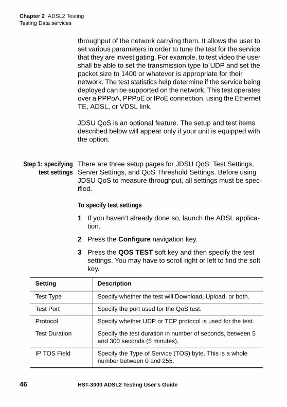
3 Press the QOS TEST soft key and then specify the test settings. You may have to scroll right or left to find the soft key.
Setting Description
Test Type Specify whether the test will Download, Upload, or both.
Test Port Specify the port used for the QoS test.
Protocol Specify whether UDP or TCP protocol is used for the test.
Test Duration Specify the test duration in number of seconds, between 5 and 300 seconds (5 minutes).
IP TOS Field Specify the Type of Service (TOS) byte. This is a whole number between 0 and 255.
Chapter 2 ADSL2 TestingTesting Data services
HST-3000 ADSL2 Testing User’s Guide 47
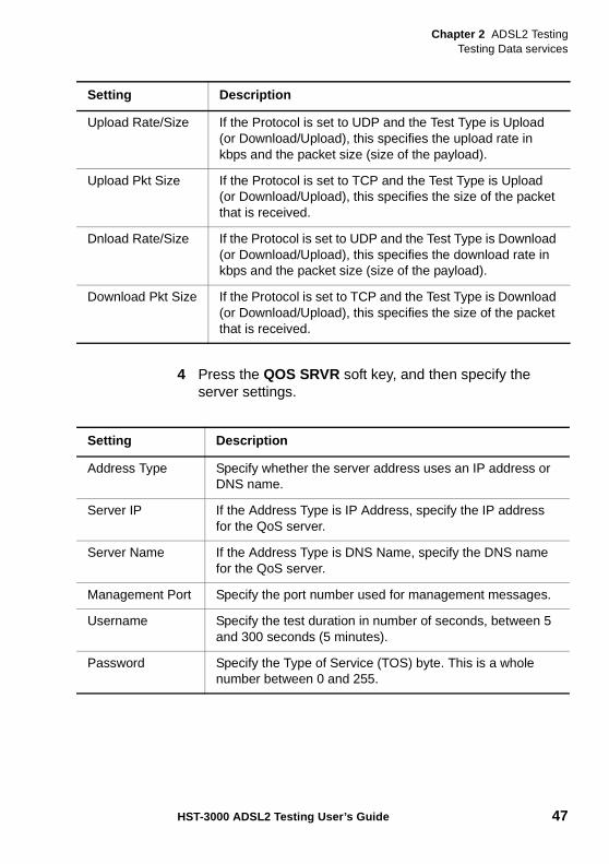
4 Press the QOS SRVR soft key, and then specify the server settings.
Upload Rate/Size If the Protocol is set to UDP and the Test Type is Upload (or Download/Upload), this specifies the upload rate in kbps and the packet size (size of the payload).
Upload Pkt Size If the Protocol is set to TCP and the Test Type is Upload (or Download/Upload), this specifies the size of the packet that is received.
Dnload Rate/Size If the Protocol is set to UDP and the Test Type is Download (or Download/Upload), this specifies the download rate in kbps and the packet size (size of the payload).
Download Pkt Size If the Protocol is set to TCP and the Test Type is Download (or Download/Upload), this specifies the size of the packet that is received.
Setting Description
Setting Description
Address Type Specify whether the server address uses an IP address or DNS name.
Server IP If the Address Type is IP Address, specify the IP address for the QoS server.
Server Name If the Address Type is DNS Name, specify the DNS name for the QoS server.
Management Port Specify the port number used for management messages.
Username Specify the test duration in number of seconds, between 5 and 300 seconds (5 minutes).
Password Specify the Type of Service (TOS) byte. This is a whole number between 0 and 255.
Chapter 2 ADSL2 TestingTesting Data services
48 HST-3000 ADSL2 Testing User’s Guide
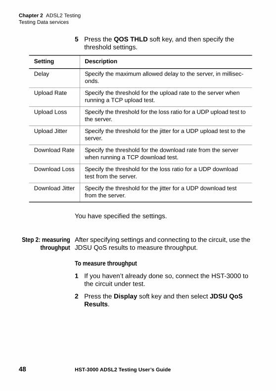
5 Press the QOS THLD soft key, and then specify the threshold settings.
You have specified the settings.
Step 2: measuringthroughput
After specifying settings and connecting to the circuit, use the JDSU QoS results to measure throughput.
To measure throughput
1 If you haven’t already done so, connect the HST-3000 to the circuit under test.
2 Press the Display soft key and then select JDSU QoS Results .
Setting Description
Delay Specify the maximum allowed delay to the server, in millisec-onds.
Upload Rate Specify the threshold for the upload rate to the server when running a TCP upload test.
Upload Loss Specify the threshold for the loss ratio for a UDP upload test to the server.
Upload Jitter Specify the threshold for the jitter for a UDP upload test to the server.
Download Rate Specify the threshold for the download rate from the server when running a TCP download test.
Download Loss Specify the threshold for the loss ratio for a UDP download test from the server.
Download Jitter Specify the threshold for the jitter for a UDP download test from the server.
Chapter 2 ADSL2 TestingFinding disturbers
HST-3000 ADSL2 Testing User’s Guide 49
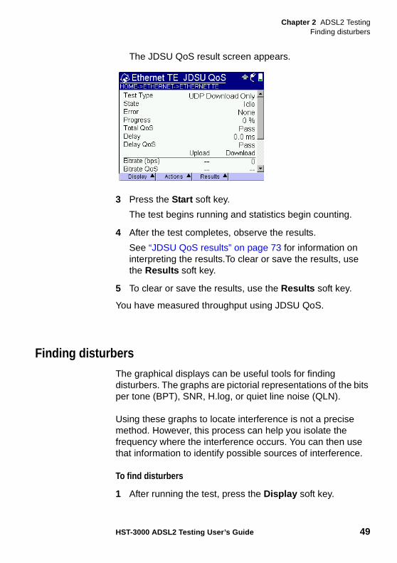
The JDSU QoS result screen appears.
3 Press the Start soft key.
The test begins running and statistics begin counting.
4 After the test completes, observe the results.
See “JDSU QoS results” on page 73 for information on interpreting the results.To clear or save the results, use the Results soft key.
5 To clear or save the results, use the Results soft key.
You have measured throughput using JDSU QoS.
Finding disturbersThe graphical displays can be useful tools for finding disturbers. The graphs are pictorial representations of the bits per tone (BPT), SNR, H.log, or quiet line noise (QLN).
Using these graphs to locate interference is not a precise method. However, this process can help you isolate the frequency where the interference occurs. You can then use that information to identify possible sources of interference.
To find disturbers
1 After running the test, press the Display soft key.
Chapter 2 ADSL2 TestingFinding disturbers
50 HST-3000 ADSL2 Testing User’s Guide
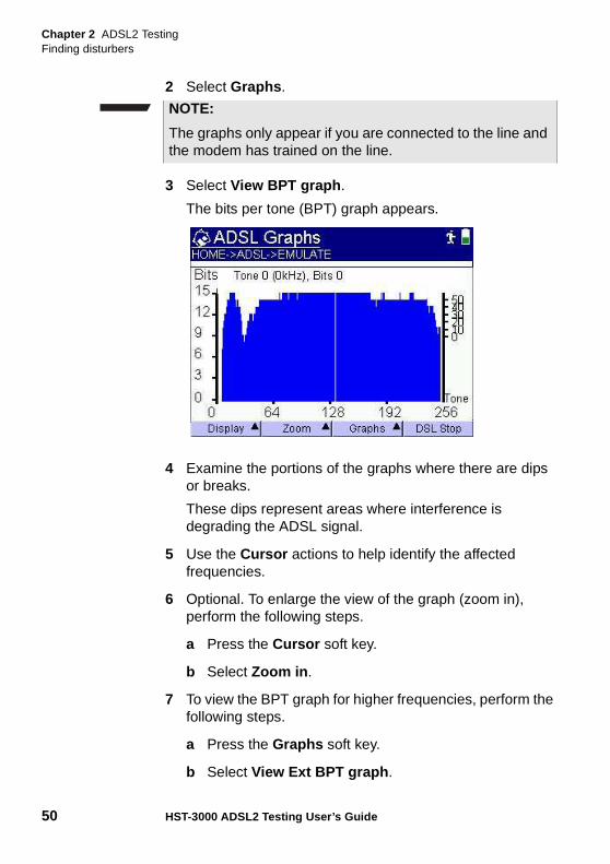
2 Select Graphs .
3 Select View BPT graph .
The bits per tone (BPT) graph appears.
4 Examine the portions of the graphs where there are dips or breaks.
These dips represent areas where interference is degrading the ADSL signal.
5 Use the Cursor actions to help identify the affected frequencies.
6 Optional. To enlarge the view of the graph (zoom in), perform the following steps.
a Press the Cursor soft key.
b Select Zoom in .
7 To view the BPT graph for higher frequencies, perform the following steps.
a Press the Graphs soft key.
b Select View Ext BPT graph .
NOTE:
The graphs only appear if you are connected to the line and the modem has trained on the line.
Chapter 2 ADSL2 TestingFinding disturbers
HST-3000 ADSL2 Testing User’s Guide 51
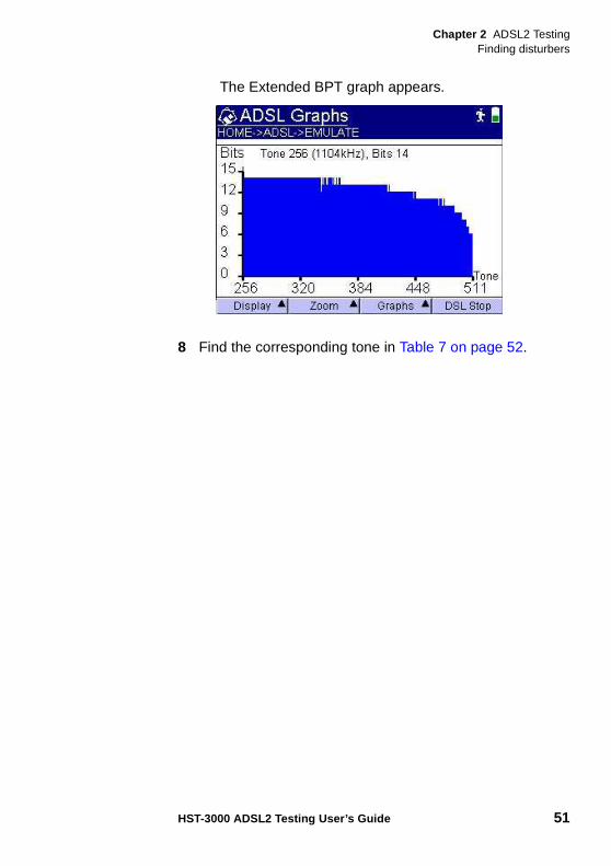
The Extended BPT graph appears.
8 Find the corresponding tone in Table 7 on page 52.
Chapter 2 ADSL2 TestingFinding disturbers
52 HST-3000 ADSL2 Testing User’s Guide
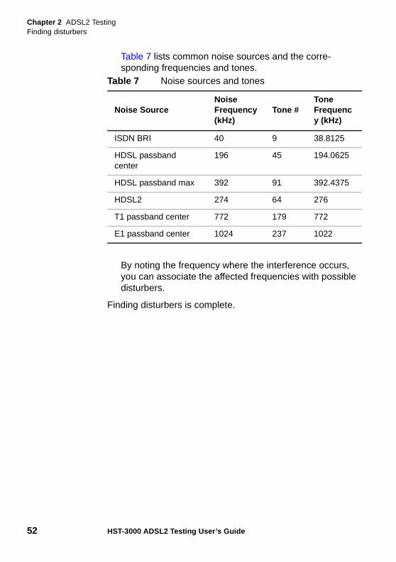
Table 7 lists common noise sources and the corre-sponding frequencies and tones.
By noting the frequency where the interference occurs, you can associate the affected frequencies with possible disturbers.
Finding disturbers is complete.
Table 7 Noise sources and tones
Noise SourceNoise Frequency (kHz)
Tone #Tone Frequency (kHz)
ISDN BRI 40 9 38.8125
HDSL passband center
196 45 194.0625
HDSL passband max 392 91 392.4375
HDSL2 274 64 276
T1 passband center 772 179 772
E1 passband center 1024 237 1022
Chapter 2 ADSL2 TestingSaving graphical results
HST-3000 ADSL2 Testing User’s Guide 53
Saving graphical resultsYou can save graphical results to a bit map file
To save graphical results to a file
1 After running a test, press the Display soft key.
2 Select Graphs .
The graphical results appear.
3 Select the graph you want to view.
4 To save the graph to a file, press the Graphs soft key.
5 Select Save Screen Capture .
6 Enter a file name for the graph, and the press the OK key.
The graph is saved to the following directory on the HST: /results/ADSL. The graph is saved as a bit map file with a .bmp file extension.
For information about viewing and printing files on the HST, see the HST-3000 Base Unit User’s Guide.
NOTE:
A graph only appears if you are connected to the line and the modem has trained on the line.
Chapter 2 ADSL2 TestingSaving graphical results
54 HST-3000 ADSL2 Testing User’s Guide
3
HST-3000 ADSL2 Testing User’s Guide 55
Chapter 3Interpreting Test Results
This chapter describes the test results that are gathered when running a test. Topics in this chapter include the following:
– “About ADSL results” on page 56
– “Modem emulate results” on page 56
– “Data mode results” on page 66
Chapter 3 Interpreting Test ResultsAbout ADSL results
56 HST-3000 ADSL2 Testing User’s Guide
About ADSL resultsAfter the HST-3000 has synchronized with the DSLAM, the unit will immediately display results on the LCD. You can view many additional results by pressing the DISPLAY soft key and selecting other results screens.
Modem emulate resultsThe following result categories are available in Modem Emulate mode:
– Summary
– Errors
– Performance
– Signal
– Graphs
– Identity
– Event log
– Dr. DSL
The following sections describe the results in each category.
NOTE:
The available results depend on the installed options, modem type, and test configuration. Your unit may not show all of the results listed below.
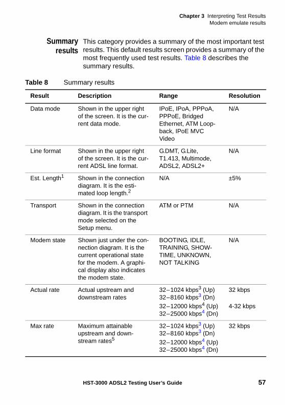
Chapter 3 Interpreting Test ResultsModem emulate results
HST-3000 ADSL2 Testing User’s Guide 57
Summaryresults
This category provides a summary of the most important test results. This default results screen provides a summary of the most frequently used test results. Table 8 describes the summary results.
Table 8 Summary results
Result Description Range Resolution
Data mode Shown in the upper right of the screen. It is the cur-rent data mode.
IPoE, IPoA, PPPoA, PPPoE, Bridged Ethernet, ATM Loop-back, IPoE MVC Video
N/A
Line format Shown in the upper right of the screen. It is the cur-rent ADSL line format.
G.DMT, G.Lite, T1.413, Multimode, ADSL2, ADSL2+
N/A
Est. Length1 Shown in the connection diagram. It is the esti-mated loop length.2
N/A ±5%
Transport Shown in the connection diagram. It is the transport mode selected on the Setup menu.
ATM or PTM N/A
Modem state Shown just under the con-nection diagram. It is the current operational state for the modem. A graphi-cal display also indicates the modem state.
BOOTING, IDLE,TRAINING, SHOW-TIME, UNKNOWN, NOT TALKING
N/A
Actual rate Actual upstream and downstream rates
32–1024 kbps3 (Up)32–8160 kbps3 (Dn)32–12000 kbps4 (Up)32–25000 kbps4 (Dn)
32 kbps
4-32 kbps
Max rate Maximum attainable upstream and down-stream rates5
32–1024 kbps3 (Up)32–8160 kbps3 (Dn)
32–12000 kbps4 (Up)32–25000 kbps4 (Dn)
32 kbps
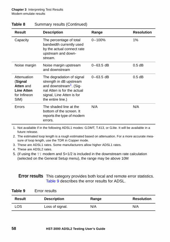
Chapter 3 Interpreting Test ResultsModem emulate results
58 HST-3000 ADSL2 Testing User’s Guide
Error results This category provides both local and remote error statistics. Table 9 describes the error results for ADSL.
Capacity The percentage of total bandwidth currently used by the actual connect rate upstream and down-stream.
0–100% 1%
Noise margin Noise margin upstream and downstream
0–63.5 dB 0.5 dB
Attenuation(Signal Atten and Line Atten for Infineon SIM)
The degradation of signal strength in dB upstream and downstream1. (Sig-nal Atten is for the actual signal, Line Atten is for the entire line.)
0–63.5 dB 0.5 dB
Errors The shaded line at the bottom of the screen. It reports the type of modem errors.
N/A N/A
1. Not available if in the following ADSL1 modes: G.DMT, T.413, or G.lite. It will be available in a future release.
2. The estimated loop length is a rough estimated based on attenuation. For a more accurate mea-sure of loop length, use the TDR in Copper mode.
3. These are ADSL1 rates. Some manufacturers allow higher ADSL1 rates.4. These are ADSL2 rates.
5. (if using the TI modem and S=1/2 is included in the downstream rate calculation (selected on the General Setup menu), the range may be above 10M
Table 8 Summary results (Continued)
Result Description Range Resolution
Table 9 Error results
Result Description Range Resolution
LOS Loss of signal. N/A N/A
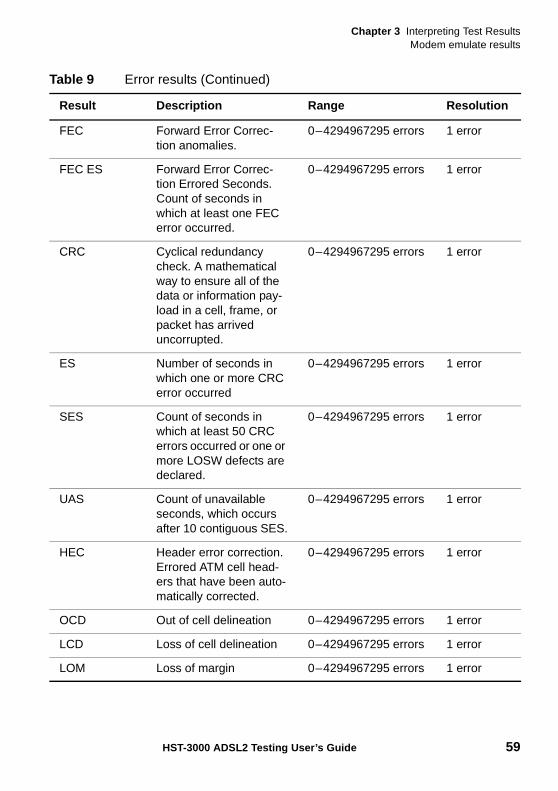
Chapter 3 Interpreting Test ResultsModem emulate results
HST-3000 ADSL2 Testing User’s Guide 59
FEC Forward Error Correc-tion anomalies.
0–4294967295 errors 1 error
FEC ES Forward Error Correc-tion Errored Seconds. Count of seconds in which at least one FEC error occurred.
0–4294967295 errors 1 error
CRC Cyclical redundancy check. A mathematical way to ensure all of the data or information pay-load in a cell, frame, or packet has arrived uncorrupted.
0–4294967295 errors 1 error
ES Number of seconds in which one or more CRC error occurred
0–4294967295 errors 1 error
SES Count of seconds in which at least 50 CRC errors occurred or one or more LOSW defects are declared.
0–4294967295 errors 1 error
UAS Count of unavailable seconds, which occurs after 10 contiguous SES.
0–4294967295 errors 1 error
HEC Header error correction. Errored ATM cell head-ers that have been auto-matically corrected.
0–4294967295 errors 1 error
OCD Out of cell delineation 0–4294967295 errors 1 error
LCD Loss of cell delineation 0–4294967295 errors 1 error
LOM Loss of margin 0–4294967295 errors 1 error
Table 9 Error results (Continued)
Result Description Range Resolution
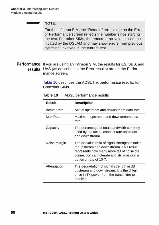
Chapter 3 Interpreting Test ResultsModem emulate results
60 HST-3000 ADSL2 Testing User’s Guide
Performanceresults
If you are using an Infineon SIM, the results for ES, SES, and UAS (as described in the Error results) are on the Perfor-mance screen.
Table 10 describes the ADSL link performance results, for Conexant SIMs.
NOTE:
For the Infineon SIM, the “Remote” error value on the Error or Performance screen reflects the number since starting the test. For other SIMs, the remote error value is commu-nicated by the DSLAM and may show errors from previous syncs not involved in the current test.
Table 10 ADSL performance results
Result Description
Actual Rate Actual upstream and downstream data rate
Max Rate Maximum upstream and downstream data rate
Capacity The percentage of total bandwidth currently used by the actual connect rate upstream and downstream.
Noise Margin The dB value ratio of signal strength to noise for upstream and downstream. This result represents how many more dB of noise the connection can tolerate and still maintain a bet error rate of 10-7.
Attenuation The degradation of signal strength in dB upstream and downstream. It is the differ-ence in Tx power from the transmitter to receiver.
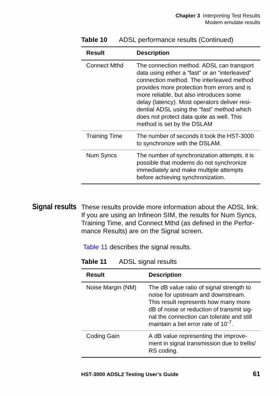
Chapter 3 Interpreting Test ResultsModem emulate results
HST-3000 ADSL2 Testing User’s Guide 61
Signal results These results provide more information about the ADSL link. If you are using an Infineon SIM, the results for Num Syncs, Training Time, and Connect Mthd (as defined in the Perfor-mance Results) are on the Signal screen.
Table 11 describes the signal results.
Connect Mthd The connection method. ADSL can transport data using either a “fast” or an “interleaved” connection method. The interleaved method provides more protection from errors and is more reliable, but also introduces some delay (latency). Most operators deliver resi-dential ADSL using the “fast” method which does not protect data quite as well. This method is set by the DSLAM
Training Time The number of seconds it took the HST-3000 to synchronize with the DSLAM.
Num Syncs The number of synchronization attempts. it is possible that modems do not synchronize immediately and make multiple attempts before achieving synchronization.
Table 10 ADSL performance results (Continued)
Result Description
Table 11 ADSL signal results
Result Description
Noise Margin (NM) The dB value ratio of signal strength to noise for upstream and downstream. This result represents how many more dB of noise or reduction of transmit sig-nal the connection can tolerate and still maintain a bet error rate of 10-7.
Coding Gain A dB value representing the improve-ment in signal transmission due to trellis/RS coding.
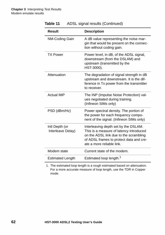
Chapter 3 Interpreting Test ResultsModem emulate results
62 HST-3000 ADSL2 Testing User’s Guide
NM-Coding Gain A dB value representing the noise mar-gin that would be present on the connec-tion without coding gain.
TX Power Power level, in dB, of the ADSL signal, downstream (from the DSLAM) and upstream (transmitted by the HST-3000).
Attenuation The degradation of signal strength in dB upstream and downstream. It is the dif-ference in Tx power from the transmitter to receiver.
Actual IMP The INP (Impulse Noise Protection) val-ues negotiated during training.(Infineon SIMs only)
PSD (dBm/Hz) Power spectral density. The portion of the power for each frequency compo-nent of the signal. (Infineon SIMs only)
Intl Depth (or Interleave Delay)
Interleaving depth set by the DSLAM. This is a measure of latency introduced on the ADSL link due to the scrambling of ADSL frames to protect data and cre-ate a more reliable link.
Modem state Current state of the modem.
Estimated Length Estimated loop length.1
1. The estimated loop length is a rough estimated based on attenuation. For a more accurate measure of loop length, use the TDR in Copper mode.
Table 11 ADSL signal results (Continued)
Result Description
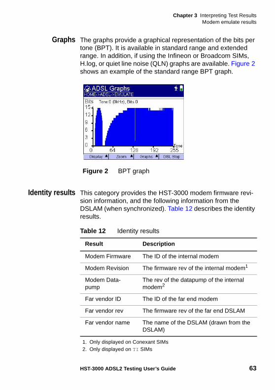
Chapter 3 Interpreting Test ResultsModem emulate results
HST-3000 ADSL2 Testing User’s Guide 63
Graphs The graphs provide a graphical representation of the bits per tone (BPT). It is available in standard range and extended range. In addition, if using the Infineon or Broadcom SIMs, H.log, or quiet line noise (QLN) graphs are available. Figure 2 shows an example of the standard range BPT graph.
Identity results This category provides the HST-3000 modem firmware revi-sion information, and the following information from the DSLAM (when synchronized). Table 12 describes the identity results.
Figure 2 BPT graph
Table 12 Identity results
Result Description
Modem Firmware The ID of the internal modem
Modem Revision The firmware rev of the internal modem1
1. Only displayed on Conexant SIMs
Modem Data-pump
The rev of the datapump of the internal modem2
2. Only displayed on TI SIMs
Far vendor ID The ID of the far end modem
Far vendor rev The firmware rev of the far end DSLAM
Far vendor name The name of the DSLAM (drawn from the DSLAM)
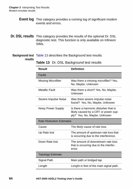
Chapter 3 Interpreting Test ResultsModem emulate results
64 HST-3000 ADSL2 Testing User’s Guide
Event log This category provides a running log of significant modem events and errors.
Dr. DSL results This category provides the results of the optional Dr. DSL diagnostic test. This function is only available on Infineon SIMs.
Background testresults
Table 13 describes the Background test results.
Table 13 Dr. DSL Background test results
Result Definition
Faults
Missing Microfilter Was there a missing microfilter? Yes, No, Maybe, Unknown
Metallic Fault Was there a short? Yes, No, Maybe, Unknown
Severe Impulse Noise Was there severe impulse noise found? Yes, No, Maybe, Unknown
Noisy Power Supply Is there a harmonic disturber that is likely caused by a CRT or power sup-ply? Yes, No, Maybe, Unknown
Rate Reduction Estimates
Cause The likely cause of rate loss.
Up Rate lost The amount of upstream rate loss that is occurring due to the interference.
Down Rate lost The amount of downstream rate loss that is occurring due to the interfer-ence.
Topology Estimate
Signal Path Main path or bridged tap
Length Lenght in feet of the main signal path.
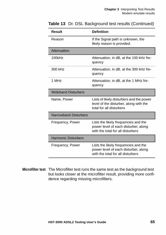
Chapter 3 Interpreting Test ResultsModem emulate results
HST-3000 ADSL2 Testing User’s Guide 65
Microfilter test The Microfilter test runs the same test as the background test but looks closer at the microfilter result, providing more confi-dence regarding missing microfilters.
Reason If the Signal path is unknown, the likely reason is provided.
Attenuation
100kHz Attenuation, in dB, at the 100 kHz fre-quency
300 kHz Attenuation, in dB, at the 300 kHz fre-quency
1 MHz Attenuation, in dB, at the 1 MHz fre-quency
Wideband Disturbers
Name, Power Lists of likely disturbers and the power level of the disturber, along with the total for all disturbers
Narrowband Disturbers
Frequency, Power Lists the likely frequencies and the power level of each disturber, along with the total for all disturbers
Harmonic Disturbers
Frequency, Power Lists the likely frequencies and the power level of each disturber, along with the total for all disturbers
Table 13 Dr. DSL Background test results (Continued)
Result Definition
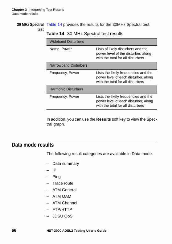
Chapter 3 Interpreting Test ResultsData mode results
66 HST-3000 ADSL2 Testing User’s Guide
30 MHz Spectraltest
Table 14 provides the results for the 30MHz Spectral test.
In addition, you can use the Results soft key to view the Spec-tral graph.
Data mode resultsThe following result categories are available in Data mode:
– Data summary
– IP
– Ping
– Trace route
– ATM General
– ATM OAM
– ATM Channel
– FTP/HTTP
– JDSU QoS
Table 14 30 MHz Spectral test results
Wideband Disturbers
Name, Power Lists of likely disturbers and the power level of the disturber, along with the total for all disturbers
Narrowband Disturbers
Frequency, Power Lists the likely frequencies and the power level of each disturber, along with the total for all disturbers
Harmonic Disturbers
Frequency, Power Lists the likely frequencies and the power level of each disturber, along with the total for all disturbers
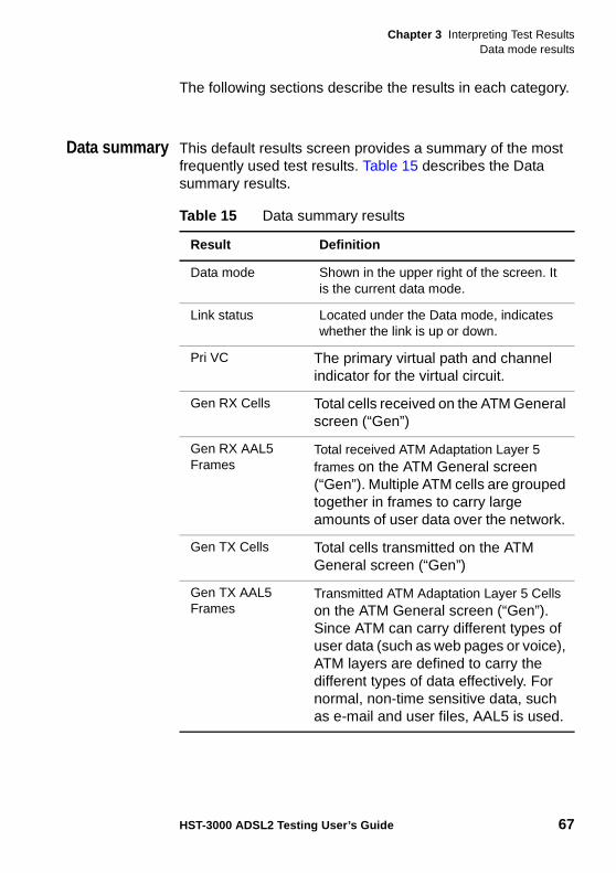
Chapter 3 Interpreting Test ResultsData mode results
HST-3000 ADSL2 Testing User’s Guide 67
The following sections describe the results in each category.
Data summary This default results screen provides a summary of the most frequently used test results. Table 15 describes the Data summary results.
Table 15 Data summary results
Result Definition
Data mode Shown in the upper right of the screen. It is the current data mode.
Link status Located under the Data mode, indicates whether the link is up or down.
Pri VC The primary virtual path and channel indicator for the virtual circuit.
Gen RX Cells Total cells received on the ATM General screen (“Gen”)
Gen RX AAL5 Frames
Total received ATM Adaptation Layer 5 frames on the ATM General screen (“Gen”). Multiple ATM cells are grouped together in frames to carry large amounts of user data over the network.
Gen TX Cells Total cells transmitted on the ATM General screen (“Gen”)
Gen TX AAL5 Frames
Transmitted ATM Adaptation Layer 5 Cells on the ATM General screen (“Gen”). Since ATM can carry different types of user data (such as web pages or voice), ATM layers are defined to carry the different types of data effectively. For normal, non-time sensitive data, such as e-mail and user files, AAL5 is used.
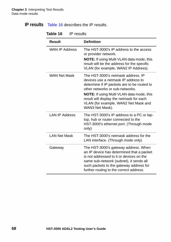
Chapter 3 Interpreting Test ResultsData mode results
68 HST-3000 ADSL2 Testing User’s Guide
IP results Table 16 describes the IP results.
Table 16 IP results
Result Definition
WAN IP Address The HST-3000's IP address to the access or provider network.
NOTE: If using Multi VLAN data mode, this result will be the address for the specific VLAN (for example, WAN2 IP Address).
WAN Net Mask The HST-3000’s netmask address. IP devices use a netmask IP address to determine if IP packets are to be routed to other networks or sub-networks.NOTE: If using Multi VLAN data mode, this result will display the netmask for each VLAN (for example, WAN2 Net Mask and WAN3 Net Mask).
LAN IP Address The HST-3000's IP address to a PC or lap-top, hub or router connected to the HST-3000's ethernet port. (Through mode only)
LAN Net Mask The HST-3000's netmask address for the LAN interface. (Through mode only)
Gateway The HST-3000's gateway address. When an IP device has determined that a packet is not addressed to it or devices on the same sub-network (subnet), it sends all such packets to the gateway address for further routing to the correct address.
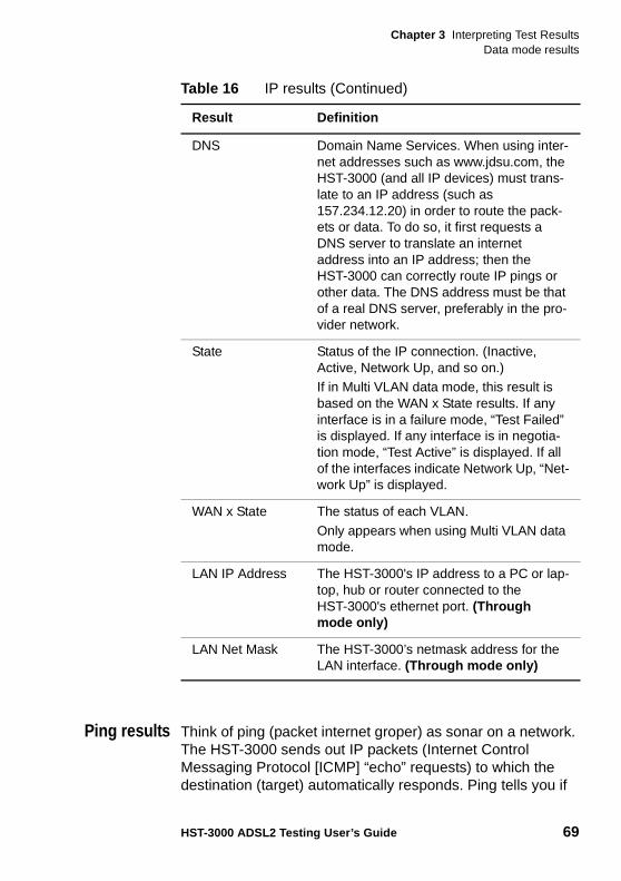
Chapter 3 Interpreting Test ResultsData mode results
HST-3000 ADSL2 Testing User’s Guide 69
Ping results Think of ping (packet internet groper) as sonar on a network. The HST-3000 sends out IP packets (Internet Control Messaging Protocol [ICMP] “echo” requests) to which the destination (target) automatically responds. Ping tells you if
DNS Domain Name Services. When using inter-net addresses such as www.jdsu.com, the HST-3000 (and all IP devices) must trans-late to an IP address (such as 157.234.12.20) in order to route the pack-ets or data. To do so, it first requests a DNS server to translate an internet address into an IP address; then the HST-3000 can correctly route IP pings or other data. The DNS address must be that of a real DNS server, preferably in the pro-vider network.
State Status of the IP connection. (Inactive, Active, Network Up, and so on.)If in Multi VLAN data mode, this result is based on the WAN x State results. If any interface is in a failure mode, “Test Failed” is displayed. If any interface is in negotia-tion mode, “Test Active” is displayed. If all of the interfaces indicate Network Up, “Net-work Up” is displayed.
WAN x State The status of each VLAN.
Only appears when using Multi VLAN data mode.
LAN IP Address The HST-3000's IP address to a PC or lap-top, hub or router connected to the HST-3000's ethernet port. (Through mode only)
LAN Net Mask The HST-3000’s netmask address for the LAN interface. (Through mode only)
Table 16 IP results (Continued)
Result Definition
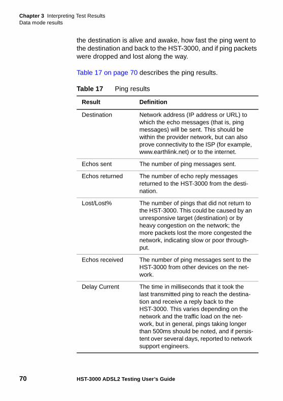
Chapter 3 Interpreting Test ResultsData mode results
70 HST-3000 ADSL2 Testing User’s Guide
the destination is alive and awake, how fast the ping went to the destination and back to the HST-3000, and if ping packets were dropped and lost along the way.
Table 17 on page 70 describes the ping results.
Table 17 Ping results
Result Definition
Destination Network address (IP address or URL) to which the echo messages (that is, ping messages) will be sent. This should be within the provider network, but can also prove connectivity to the ISP (for example, www.earthlink.net) or to the internet.
Echos sent The number of ping messages sent.
Echos returned The number of echo reply messages returned to the HST-3000 from the desti-nation.
Lost/Lost% The number of pings that did not return to the HST-3000. This could be caused by an unresponsive target (destination) or by heavy congestion on the network; the more packets lost the more congested the network, indicating slow or poor through-put.
Echos received The number of ping messages sent to the HST-3000 from other devices on the net-work.
Delay Current The time in milliseconds that it took the last transmitted ping to reach the destina-tion and receive a reply back to the HST-3000. This varies depending on the network and the traffic load on the net-work, but in general, pings taking longer than 500ms should be noted, and if persis-tent over several days, reported to network support engineers.
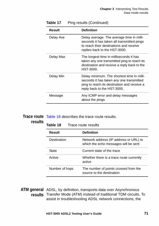
Chapter 3 Interpreting Test ResultsData mode results
HST-3000 ADSL2 Testing User’s Guide 71
Trace routeresults
Table 18 describes the trace route results.
ATM generalresults
ADSL, by definition, transports data over Asynchronous Transfer Mode (ATM) instead of traditional TDM circuits. To assist in troubleshooting ADSL network connections, the
Delay Ave Delay average. The average time in milli-seconds it has taken all transmitted pings to reach their destinations and receive replies back to the HST-3000.
Delay Max The longest time in milliseconds it has taken any one transmitted ping to reach its destination and receive a reply back to the HST-3000.
Delay Min Delay minimum. The shortest time in milli-seconds it has taken any one transmitted ping to reach its destination and receive a reply back to the HST-3000.
Message Any ICMP error and delay messages about the pings
Table 17 Ping results (Continued)
Result Definition
Table 18 Trace route results
Result Definition
Destination Network address (IP address or URL) to which the echo messages will be sent
State Current state of the trace
Active Whether there is a trace route currently active
Number of hops The number of points crossed from the source to the destination
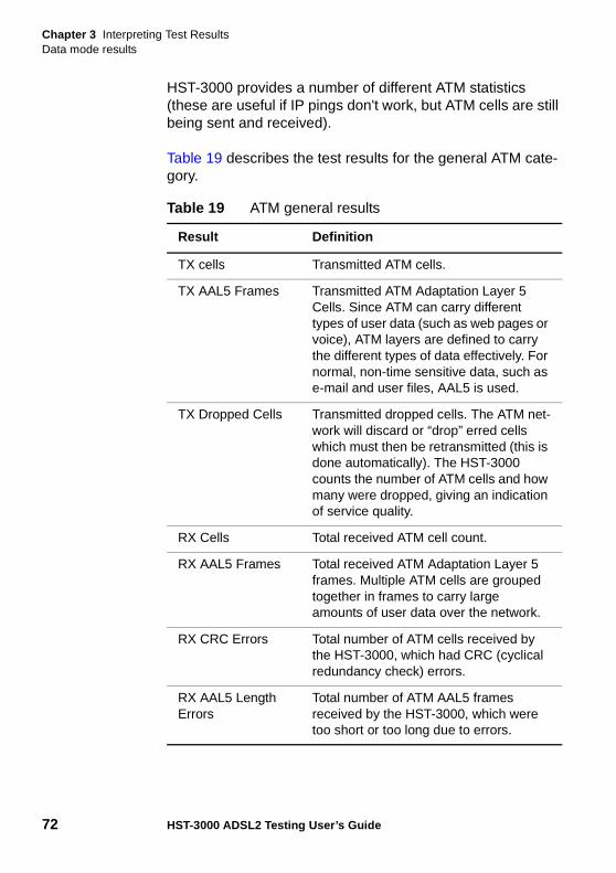
Chapter 3 Interpreting Test ResultsData mode results
72 HST-3000 ADSL2 Testing User’s Guide
HST-3000 provides a number of different ATM statistics (these are useful if IP pings don't work, but ATM cells are still being sent and received).
Table 19 describes the test results for the general ATM cate-gory.
Table 19 ATM general results
Result Definition
TX cells Transmitted ATM cells.
TX AAL5 Frames Transmitted ATM Adaptation Layer 5 Cells. Since ATM can carry different types of user data (such as web pages or voice), ATM layers are defined to carry the different types of data effectively. For normal, non-time sensitive data, such as e-mail and user files, AAL5 is used.
TX Dropped Cells Transmitted dropped cells. The ATM net-work will discard or “drop” erred cells which must then be retransmitted (this is done automatically). The HST-3000 counts the number of ATM cells and how many were dropped, giving an indication of service quality.
RX Cells Total received ATM cell count.
RX AAL5 Frames Total received ATM Adaptation Layer 5 frames. Multiple ATM cells are grouped together in frames to carry large amounts of user data over the network.
RX CRC Errors Total number of ATM cells received by the HST-3000, which had CRC (cyclical redundancy check) errors.
RX AAL5 Length Errors
Total number of ATM AAL5 frames received by the HST-3000, which were too short or too long due to errors.
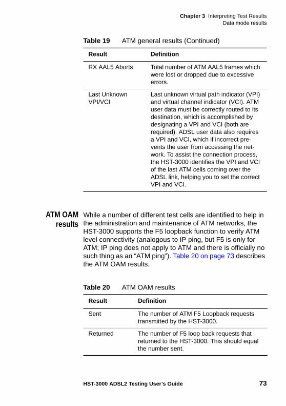
Chapter 3 Interpreting Test ResultsData mode results
HST-3000 ADSL2 Testing User’s Guide 73
ATM OAMresults
While a number of different test cells are identified to help in the administration and maintenance of ATM networks, the HST-3000 supports the F5 loopback function to verify ATM level connectivity (analogous to IP ping, but F5 is only for ATM; IP ping does not apply to ATM and there is officially no such thing as an “ATM ping”). Table 20 on page 73 describes the ATM OAM results.
RX AAL5 Aborts Total number of ATM AAL5 frames which were lost or dropped due to excessive errors.
Last Unknown VPI/VCI
Last unknown virtual path indicator (VPI) and virtual channel indicator (VCI). ATM user data must be correctly routed to its destination, which is accomplished by designating a VPI and VCI (both are required). ADSL user data also requires a VPI and VCI, which if incorrect pre-vents the user from accessing the net-work. To assist the connection process, the HST-3000 identifies the VPI and VCI of the last ATM cells coming over the ADSL link, helping you to set the correct VPI and VCI.
Table 19 ATM general results (Continued)
Result Definition
Table 20 ATM OAM results
Result Definition
Sent The number of ATM F5 Loopback requests transmitted by the HST-3000.
Returned The number of F5 loop back requests that returned to the HST-3000. This should equal the number sent.
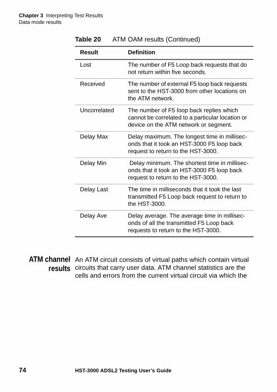
Chapter 3 Interpreting Test ResultsData mode results
74 HST-3000 ADSL2 Testing User’s Guide
ATM channelresults
An ATM circuit consists of virtual paths which contain virtual circuits that carry user data. ATM channel statistics are the cells and errors from the current virtual circuit via which the
Lost The number of F5 Loop back requests that do not return within five seconds.
Received The number of external F5 loop back requests sent to the HST-3000 from other locations on the ATM network.
Uncorrelated The number of F5 loop back replies which cannot be correlated to a particular location or device on the ATM network or segment.
Delay Max Delay maximum. The longest time in millisec-onds that it took an HST-3000 F5 loop back request to return to the HST-3000.
Delay Min Delay minimum. The shortest time in millisec-onds that it took an HST-3000 F5 loop back request to return to the HST-3000.
Delay Last The time in milliseconds that it took the last transmitted F5 Loop back request to return to the HST-3000.
Delay Ave Delay average. The average time in millisec-onds of all the transmitted F5 Loop back requests to return to the HST-3000.
Table 20 ATM OAM results (Continued)
Result Definition
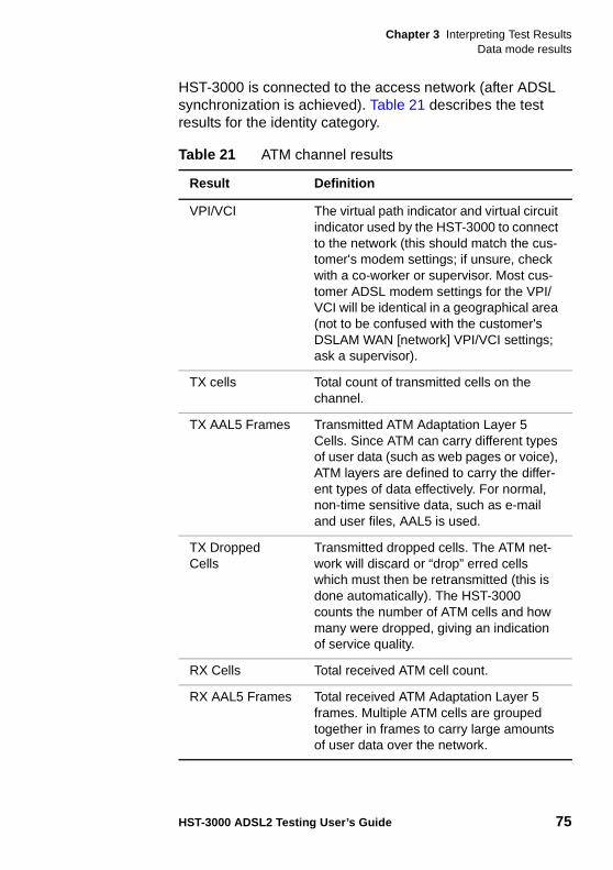
Chapter 3 Interpreting Test ResultsData mode results
HST-3000 ADSL2 Testing User’s Guide 75
HST-3000 is connected to the access network (after ADSL synchronization is achieved). Table 21 describes the test results for the identity category.
Table 21 ATM channel results
Result Definition
VPI/VCI The virtual path indicator and virtual circuit indicator used by the HST-3000 to connect to the network (this should match the cus-tomer's modem settings; if unsure, check with a co-worker or supervisor. Most cus-tomer ADSL modem settings for the VPI/VCI will be identical in a geographical area (not to be confused with the customer's DSLAM WAN [network] VPI/VCI settings; ask a supervisor).
TX cells Total count of transmitted cells on the channel.
TX AAL5 Frames Transmitted ATM Adaptation Layer 5 Cells. Since ATM can carry different types of user data (such as web pages or voice), ATM layers are defined to carry the differ-ent types of data effectively. For normal, non-time sensitive data, such as e-mail and user files, AAL5 is used.
TX Dropped Cells
Transmitted dropped cells. The ATM net-work will discard or “drop” erred cells which must then be retransmitted (this is done automatically). The HST-3000 counts the number of ATM cells and how many were dropped, giving an indication of service quality.
RX Cells Total received ATM cell count.
RX AAL5 Frames Total received ATM Adaptation Layer 5 frames. Multiple ATM cells are grouped together in frames to carry large amounts of user data over the network.
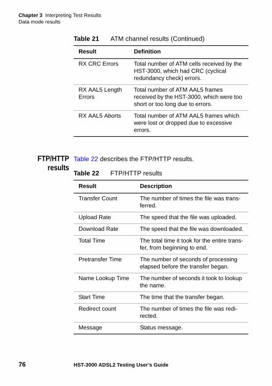
Chapter 3 Interpreting Test ResultsData mode results
76 HST-3000 ADSL2 Testing User’s Guide
FTP/HTTPresults
Table 22 describes the FTP/HTTP results.
RX CRC Errors Total number of ATM cells received by the HST-3000, which had CRC (cyclical redundancy check) errors.
RX AAL5 Length Errors
Total number of ATM AAL5 frames received by the HST-3000, which were too short or too long due to errors.
RX AAL5 Aborts Total number of ATM AAL5 frames which were lost or dropped due to excessive errors.
Table 21 ATM channel results (Continued)
Result Definition
Table 22 FTP/HTTP results
Result Description
Transfer Count The number of times the file was trans-ferred.
Upload Rate The speed that the file was uploaded.
Download Rate The speed that the file was downloaded.
Total Time The total time it took for the entire trans-fer, from beginning to end.
Pretransfer Time The number of seconds of processing elapsed before the transfer began.
Name Lookup Time The number of seconds it took to lookup the name.
Start Time The time that the transfer began.
Redirect count The number of times the file was redi-rected.
Message Status message.
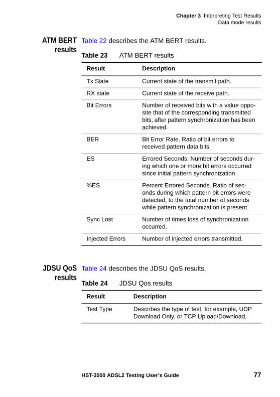
Chapter 3 Interpreting Test ResultsData mode results
HST-3000 ADSL2 Testing User’s Guide 77
ATM BERTresults
Table 22 describes the ATM BERT results.
JDSU QoSresults
Table 24 describes the JDSU QoS results.
Table 23 ATM BERT results
Result Description
Tx State Current state of the transmit path.
RX state Current state of the receive path.
Bit Errors Number of received bits with a value oppo-site that of the corresponding transmitted bits, after pattern synchronization has been achieved.
BER Bit Error Rate. Ratio of bit errors to received pattern data bits
ES Errored Seconds. Number of seconds dur-ing which one or more bit errors occurred since initial pattern synchronization
%ES Percent Errored Seconds. Ratio of sec-onds during which pattern bit errors were detected, to the total number of seconds while pattern synchronization is present.
Sync Lost Number of times loss of synchronization occurred.
Injected Errors Number of injected errors transmitted.
Table 24 JDSU Qos results
Result Description
Test Type Describes the type of test, for example, UDP Download Only, or TCP Upload/Download.
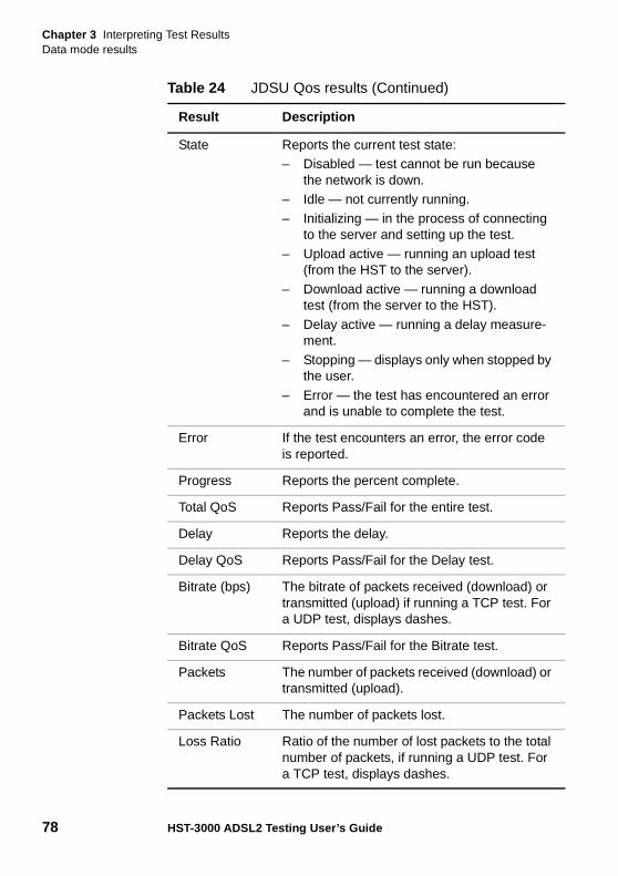
Chapter 3 Interpreting Test ResultsData mode results
78 HST-3000 ADSL2 Testing User’s Guide
State Reports the current test state: – Disabled — test cannot be run because
the network is down.– Idle — not currently running.
– Initializing — in the process of connecting to the server and setting up the test.
– Upload active — running an upload test (from the HST to the server).
– Download active — running a download test (from the server to the HST).
– Delay active — running a delay measure-ment.
– Stopping — displays only when stopped by the user.
– Error — the test has encountered an error and is unable to complete the test.
Error If the test encounters an error, the error code is reported.
Progress Reports the percent complete.
Total QoS Reports Pass/Fail for the entire test.
Delay Reports the delay.
Delay QoS Reports Pass/Fail for the Delay test.
Bitrate (bps) The bitrate of packets received (download) or transmitted (upload) if running a TCP test. For a UDP test, displays dashes.
Bitrate QoS Reports Pass/Fail for the Bitrate test.
Packets The number of packets received (download) or transmitted (upload).
Packets Lost The number of packets lost.
Loss Ratio Ratio of the number of lost packets to the total number of packets, if running a UDP test. For a TCP test, displays dashes.
Table 24 JDSU Qos results (Continued)
Result Description
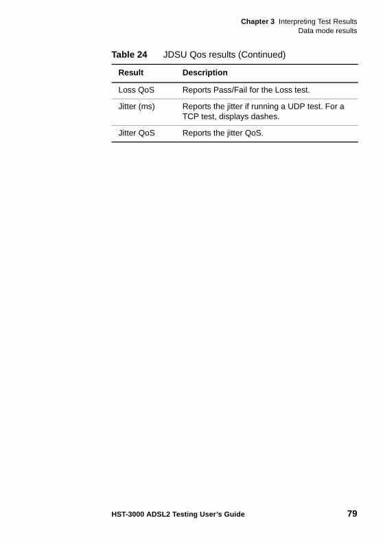
Chapter 3 Interpreting Test ResultsData mode results
HST-3000 ADSL2 Testing User’s Guide 79
Loss QoS Reports Pass/Fail for the Loss test.
Jitter (ms) Reports the jitter if running a UDP test. For a TCP test, displays dashes.
Jitter QoS Reports the jitter QoS.
Table 24 JDSU Qos results (Continued)
Result Description
Chapter 3 Interpreting Test ResultsData mode results
80 HST-3000 ADSL2 Testing User’s Guide
4
HST-3000 ADSL2 Testing User’s Guide 81
Chapter 4Troubleshooting
This chapter describes how to identify and correct problems related to the HST-3000. Topics discussed in this chapter include the following:
– “Interpreting messages” on page 82
– “Resolving problems” on page 85
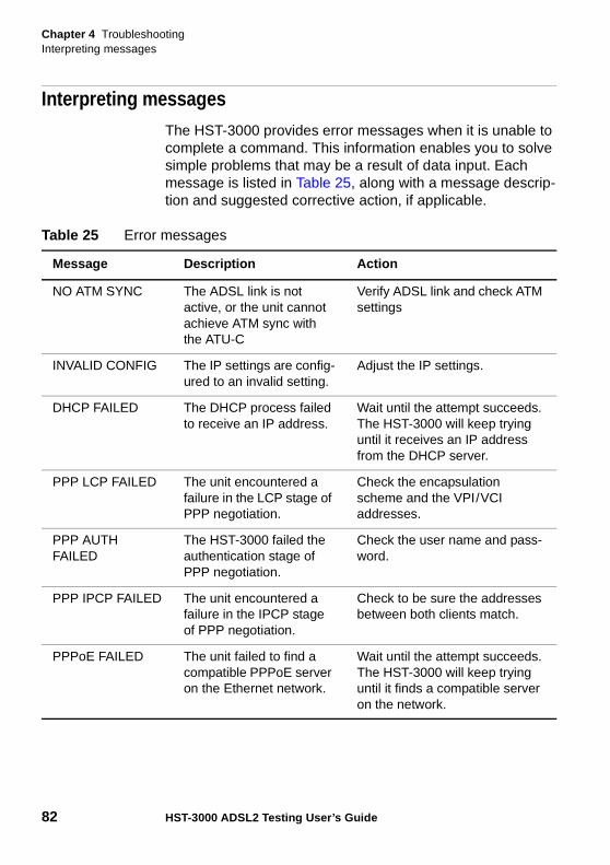
Chapter 4 TroubleshootingInterpreting messages
82 HST-3000 ADSL2 Testing User’s Guide
Interpreting messagesThe HST-3000 provides error messages when it is unable to complete a command. This information enables you to solve simple problems that may be a result of data input. Each message is listed in Table 25, along with a message descrip-tion and suggested corrective action, if applicable.
Table 25 Error messages
Message Description Action
NO ATM SYNC The ADSL link is not active, or the unit cannot achieve ATM sync with the ATU-C
Verify ADSL link and check ATM settings
INVALID CONFIG The IP settings are config-ured to an invalid setting.
Adjust the IP settings.
DHCP FAILED The DHCP process failed to receive an IP address.
Wait until the attempt succeeds. The HST-3000 will keep trying until it receives an IP address from the DHCP server.
PPP LCP FAILED The unit encountered a failure in the LCP stage of PPP negotiation.
Check the encapsulation scheme and the VPI/VCI addresses.
PPP AUTH FAILED
The HST-3000 failed the authentication stage of PPP negotiation.
Check the user name and pass-word.
PPP IPCP FAILED The unit encountered a failure in the IPCP stage of PPP negotiation.
Check to be sure the addresses between both clients match.
PPPoE FAILED The unit failed to find a compatible PPPoE server on the Ethernet network.
Wait until the attempt succeeds. The HST-3000 will keep trying until it finds a compatible server on the network.
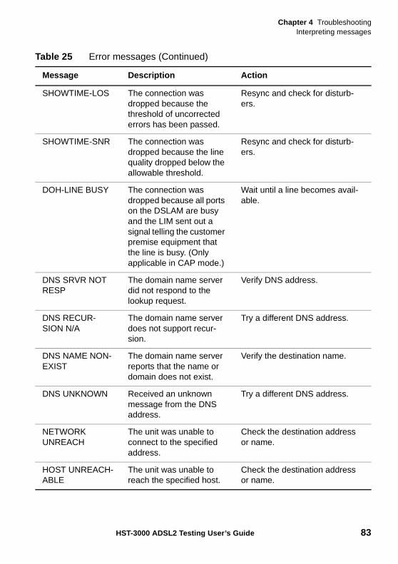
Chapter 4 TroubleshootingInterpreting messages
HST-3000 ADSL2 Testing User’s Guide 83
SHOWTIME-LOS The connection was dropped because the threshold of uncorrected errors has been passed.
Resync and check for disturb-ers.
SHOWTIME-SNR The connection was dropped because the line quality dropped below the allowable threshold.
Resync and check for disturb-ers.
DOH-LINE BUSY The connection was dropped because all ports on the DSLAM are busy and the LIM sent out a signal telling the customer premise equipment that the line is busy. (Only applicable in CAP mode.)
Wait until a line becomes avail-able.
DNS SRVR NOT RESP
The domain name server did not respond to the lookup request.
Verify DNS address.
DNS RECUR-SION N/A
The domain name server does not support recur-sion.
Try a different DNS address.
DNS NAME NON-EXIST
The domain name server reports that the name or domain does not exist.
Verify the destination name.
DNS UNKNOWN Received an unknown message from the DNS address.
Try a different DNS address.
NETWORK UNREACH
The unit was unable to connect to the specified address.
Check the destination address or name.
HOST UNREACH-ABLE
The unit was unable to reach the specified host.
Check the destination address or name.
Table 25 Error messages (Continued)
Message Description Action
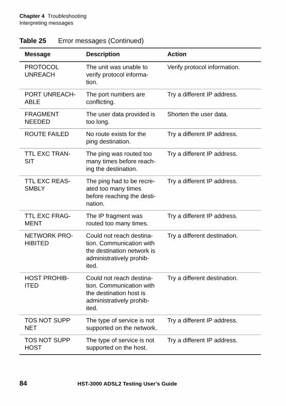
Chapter 4 TroubleshootingInterpreting messages
84 HST-3000 ADSL2 Testing User’s Guide
PROTOCOL UNREACH
The unit was unable to verify protocol informa-tion.
Verify protocol information.
PORT UNREACH-ABLE
The port numbers are conflicting.
Try a different IP address.
FRAGMENT NEEDED
The user data provided is too long.
Shorten the user data.
ROUTE FAILED No route exists for the ping destination.
Try a different IP address.
TTL EXC TRAN-SIT
The ping was routed too many times before reach-ing the destination.
Try a different IP address.
TTL EXC REAS-SMBLY
The ping had to be recre-ated too many times before reaching the desti-nation.
Try a different IP address.
TTL EXC FRAG-MENT
The IP fragment was routed too many times.
Try a different IP address.
NETWORK PRO-HIBITED
Could not reach destina-tion. Communication with the destination network is administratively prohib-ited.
Try a different destination.
HOST PROHIB-ITED
Could not reach destina-tion. Communication with the destination host is administratively prohib-ited.
Try a different destination.
TOS NOT SUPP NET
The type of service is not supported on the network.
Try a different IP address.
TOS NOT SUPP HOST
The type of service is not supported on the host.
Try a different IP address.
Table 25 Error messages (Continued)
Message Description Action
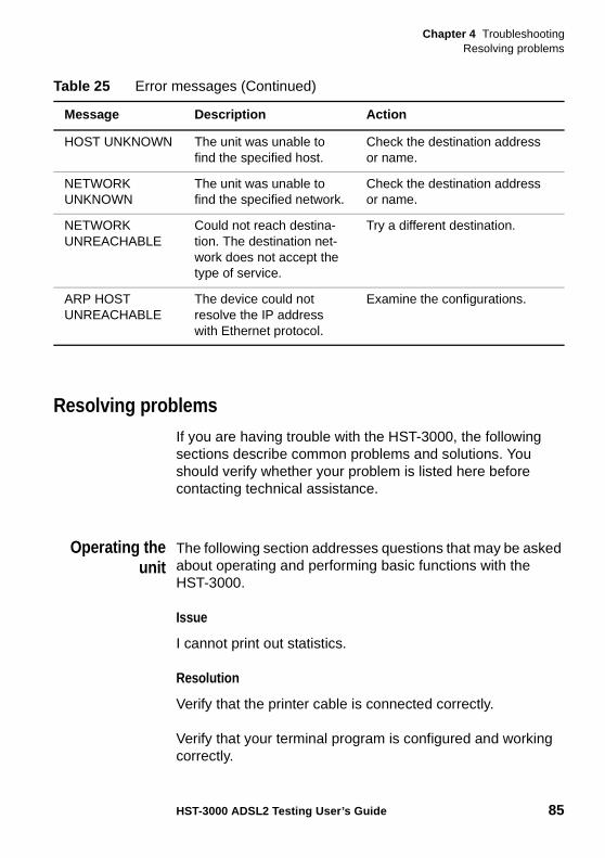
Chapter 4 TroubleshootingResolving problems
HST-3000 ADSL2 Testing User’s Guide 85
Resolving problemsIf you are having trouble with the HST-3000, the following sections describe common problems and solutions. You should verify whether your problem is listed here before contacting technical assistance.
Operating theunit
The following section addresses questions that may be asked about operating and performing basic functions with the HST-3000.
Issue
I cannot print out statistics.
Resolution
Verify that the printer cable is connected correctly.
Verify that your terminal program is configured and working correctly.
HOST UNKNOWN The unit was unable to find the specified host.
Check the destination address or name.
NETWORK UNKNOWN
The unit was unable to find the specified network.
Check the destination address or name.
NETWORK UNREACHABLE
Could not reach destina-tion. The destination net-work does not accept the type of service.
Try a different destination.
ARP HOST UNREACHABLE
The device could not resolve the IP address with Ethernet protocol.
Examine the configurations.
Table 25 Error messages (Continued)
Message Description Action
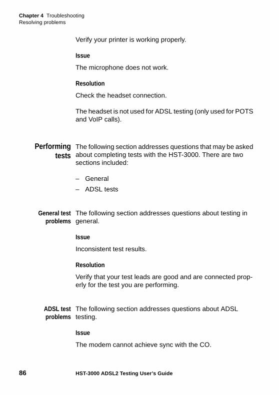
Chapter 4 TroubleshootingResolving problems
86 HST-3000 ADSL2 Testing User’s Guide
Verify your printer is working properly.
Issue
The microphone does not work.
Resolution
Check the headset connection.
The headset is not used for ADSL testing (only used for POTS and VoIP calls).
Performingtests
The following section addresses questions that may be asked about completing tests with the HST-3000. There are two sections included:
– General
– ADSL tests
General testproblems
The following section addresses questions about testing in general.
Issue
Inconsistent test results.
Resolution
Verify that your test leads are good and are connected prop-erly for the test you are performing.
ADSL testproblems
The following section addresses questions about ADSL testing.
Issue
The modem cannot achieve sync with the CO.
Chapter 4 TroubleshootingResolving problems
HST-3000 ADSL2 Testing User’s Guide 87
Resolution
Inability to sync can have many causes. Perform the following steps to troubleshoot:
– Disconnect the customer's ADSL modem.
– Verify tester connection to the correct pair.
– Verify that the ADSL standard is correct (T1.413, G.DMT, G.Lite, or CAP).
– Isolate premise wiring.
– Check for premise alarm system.
– Verify the copper pair is provisioned for ADSL at the CO.
– Test at the CO/Exchange on the customer pair.
– Check the DSLAM modem vendor and software version.
Issue
The modem gets sync with the CO, but the rate is lower than expected.
Resolution
Verify that you are on an ADSL2 or ADSL2+ line.
Check the bits/tone and the SNR/tone for areas of the spec-trum with low throughput. This could be caused by bridged taps, cable crosstalk, or AM radio.
Use the HST-3000 to check physical conditions: DVOM, balance, opens, and use the TDR to check for bridged taps.
Check the DSLAM configuration - the max rate may be limited there.
Check for premise alarm system on the same pair.
Avoid excessive loop length or high attenuation.
Chapter 4 TroubleshootingResolving problems
88 HST-3000 ADSL2 Testing User’s Guide
Make sure that you are connected on pins 4 and 5.
Verify the noise margin.
Issue
In through mode, I’m connected to the Ethernet connector, but I’m not getting a data connection (green LED on the Ethernet connector is on, but the yellow LED is not).
Resolution
Go to the LAN Settings screen and check the Media Type. If it’s set to Auto, change it to match the specific LAN speed and duplex type that you are using.
Issue
The ping menu says pings are being sent, but the network statistics are not incrementing.
Resolution
The ping function only attempts to send a ping every second. Depending on certain conditions, a physical ping packet may not be sent.
Check that the unit has not lost sync.
If IPoE data mode is being used, the device has to ARP the address first. If this fails eventually you will see a ARP HOST UNREACHABLE message. Check to see that the destination IP address and your configured IP settings are correct.
If the Ethernet interface is being used, make sure that the cabling is correct. If the Ethernet cable is not hooked up, or is hooked up incorrectly, a packet will not be sent. Thus the Ethernet statistics will not increment.
Check the Ethernet link light on the HST-3000 Ethernet jack. It should be green.
Chapter 4 TroubleshootingResolving problems
HST-3000 ADSL2 Testing User’s Guide 89
Issue
The ping menu says pings are being sent, but the number of replies doesn’t match the pings sent.
Resolution
Check the TX ATM PCR value on the Data settings screen. If the PCR is set too low, ping replies will be lost. This is because the “number of pings” selection (on the Ping settings) is defined as the number of pings per second and the PCR value is set as cells per second. Thus, if you are sending more pings than the PCR allows, you will not receive ping replies.
To resolve this, do one of the following:
– Set the number of pings to 1
– Set the PCR to 1000 or unlimited.
Issue
The ATM total statistics are incrementing but the channel stats are not incrementing.
Resolution
Reconfigure the interface to match the VPI/VCI given in the VPI/VCI of Last Unknown Cell statistic.
Issue
The ATM channel statistics indicate that I am receiving frames but I did not get a green Data LED and pings are not working.
Resolution
Check the encapsulation and the mode. The wrong protocol may be in use.
Issue
I have a PPPoA service and I get a PPP TIMEOUT message
Chapter 4 TroubleshootingResolving problems
90 HST-3000 ADSL2 Testing User’s Guide
Resolution
Verify that the VPI-VCI is correct.
Verify that the encapsulation is correct.
Verify that the addressing mode is set correctly (IPCP/Static).
Verify that the username and password are correct.
Issue
I have a PPPoE connection and I get a PPPoE FAILED message.
Resolution
Verify that the VPI-VCI is correct.
Verify that the encapsulation is correct.
Verify that the addressing mode is correct.
Verify that the user name and password are correct (including case)
Issue
I have a Bridged Ethernet connection and I get a DCHP FAILED message.
Resolution
Verify that the VPI-VCI is correct.
Verify that the encapsulation is correct.
Verify that the DHCP server isn't out of addresses. (Contact your IT department or help desk.)
Issue
I get an INVALID CONFIG message.
Chapter 4 TroubleshootingResolving problems
HST-3000 ADSL2 Testing User’s Guide 91
Resolution
Verify that a valid IP address is being used (examples of invalid IP addresses would be *.*.*.0 or 127.*.*.* or 10.0.0.1 or 192.168.0.0).
Verify that the IP address and gateway are on the same network as defined by the netmask.
Check the netmasks if Ethernet IP = DSL IP. The netmasks must be different.
Verify that the Netmask is not set to 0.0.0.0.
Issue
I have a green Data LED, but pings are not working.
Resolution
A green Data LED does not guarantee a ping (or any routed/bridged packet) will be treated properly once it leaves the unit. In an Ethernet bridged or IP over ATM environment with static addressing, there is no initial communication with the far end, so as soon as ATM sync occurs the interface is deemed active to pass user data.
Make sure that the VPI and VCI is correct.
Make sure that the encapsulation is correct.
Try pinging a different host.
Make sure the DNS server is active with another PC.
Set the PING packet size smaller.
Make sure the HST Data mode is set correctly for the type of circuit under test (such as PPPoE versus IPoE).
Make sure you are not behind a firewall; they can block ping responses from reaching the host.
Chapter 4 TroubleshootingResolving problems
92 HST-3000 ADSL2 Testing User’s Guide
Check to see if the connection is unnumbered. If it is, verify that the connection is configured correctly.
View the Results>Data>Ping menu. It can often give important clues as to why the ping is not successful.
Issue
I get a message that is not listed when I am performing tests.
Resolution
You may receive an unspecified or unknown error message while you are testing ADSL lines. This is because of the many different possible types of ADSL modem errors. If you receive one of these messages, try the following:
Try to resync with the line.
Check the configuration of the HST-3000.
Check the configuration of the DSLAM.
Issue
The Sync LED is lit, but the Data LED is not lit.
Resolution
Verify that the Data Mode is not set to Off.
If you are on an IPoE line and STUN is enabled, the data layer will not come up until the STUN client on the HST has deter-mined the type of NAT used between the HST and the STUN server. Wait a few minutes and try to resync.
HST-3000 ADSL2 Testing User’s Guide 93
Glossary
A
Actual Down Rate — Bearer channel rate downstream.
Actual Up Rate — Bearer channel rate upstream.
ADSL — Asymmetric Digital Subscriber Line. A digital subscriber line (DSL) tech-nology in which the transmission of data from server to client is much faster than the transmis-sion from the client to the server. The difference in ADSL1 vs. ADSL2/2+ is the standard that defines them:
• ADSL1: ITU G.992.2.
• ADSL2: ITU G.992.3 and .4.
• ADSL2+: ITU G.992.5.
ADSLAM — Advanced Digital Subscriber Line Access Multi-plexer. Concentrates and multi-plexes signals at the telephone service provider location to the broader wide area network.
ATM — Asynchronous Transfer Mode. A cell-based data transfer technique in which channel demand determines packet allo-cation. ATM offers fast packet technology, real time, demand lead switching for efficient use of network resources.
Auto-Negotiation — Proce-dure for adjusting line speeds and other communication settings automatically between two computers during data transfer.
Glossary
94 HST-3000 ADSL2 Testing User’s Guide
B
BER — Bit Error Rate.
Bit error — Received bits with a value opposite that of the corre-sponding transmitted bits. Also called a test sequence error (TSE).
Bits per tone — This measure-ment and display allows anal-ysis of the bits assigned per DMT tone (256 tones). By looking for any significant dips, that is, an average number across all tones is present but for a few the number is zero or much longer, the presence of AC interference can be identi-fied.
Bps — Bits per second.
C
CAP — Carrierless Amplitude Phase. A line coding used for ADSL.
CO — Central Office.
Cell — A fixed length unit of information. Most other data units can vary in length, but a cell is fixed in size. This helps cut down on network delays and variations in the delay through a network.
Crosstalk — The interference caused by signals on adjacent circuits in a network.
CPE — Customer Premise Equipment. Devices or equip-ment that the customer provides to interface with the telco.
D
Delay — A contributing measure of the carrying capacity of a link. Delay indicates how long it takes bits to find their way through a network.
Digital — Having only discrete values, such as 0 or 1.
DMT — Discrete Multi-Tone. A line coding used for ADSL.
Downstream Rate — The line rate for return messages or data transfers from the network machine to the user's customer's premise machine.
DSL — Digital Subscriber Line. A generic name for a family of standards allowing high-speed data transfer over telephone lines.
DSLAM — Digital Subscriber Line Access Multiplexer.
Glossary
HST-3000 ADSL2 Testing User’s Guide 95
DSU/CSU — Data Service Unit/Channel Service Unit -The inter-face device required to change one form of digital signal to another.
DTMF — Dual Tone Multi-Frequency. A voice-band tone-based method of signaling.
E
Echo — The reflecting of a signal back to its source due to a variety of reasons.
Encapsulation — The tech-nique used by layered protocols in which a layer adds header information to the protocol data unit (PDU) from the layer above.
Ethernet — A local area network (LAN) wiring scheme. You can use the HST-3000 to emulate Ethernet terminal equipment to test connectivity.
G
Gateway — A system which does translation from some native format to another.
G.Lite — A lower-speed cousin of ADSL. It offers the advantage of being an ITU standard.
I
ICMP — Internet Configuration Message Protocol. The protocol used to handle errors and control messages at the IP layer. ICMP is actually part of the IP protocol.
Internet Protocol (IP) — The network layer protocol for the Internet protocol suite.
IP Address — The 32-bit address assigned to hosts that want to participate in a TCP/IP Internet.
L
L2 — Low power mode where the transceiver modifies power based on traffic.
L3 — Low power mode where each end enters sleep mode when the connection is not being used for extended periods.
LAN — Local Area Network. A limited distance (typically under a few kilometers or a couple of miles) high-speed network (typi-cally 4 to 100 Mbps) that supports many computers.
LED — Light Emitting Diode. The lights indicating status or activity on electronic equipment.
Glossary
96 HST-3000 ADSL2 Testing User’s Guide
LiIon — Lithium Ion. A type of rechargeable battery.
Line Quality — Equivalent to SNR. It is called this to be equiv-alent with the Cisco modem.
Line Rate — The speed by which data is transferred over a particular line type, express in bits per second (bps).
Local Gain — Receiver gain in the downstream direction in dB. Note that this can be (and often is) negative.
Local Transmit Power —
Transmit power in dBm in the upstream direction. Note that this can be (and often is) nega-tive.
Loopback — A diagnostic test that returns the transmitted signal back to the sending device after is has passed through a network or across a particular link. The returned signal can then be compared to the transmitted one. The discrepancy between the two help to trace the fault.
M
Modem Pooling — The ability of a service provider to dynami-cally switch users' messages between modems, rather than requiring a modem to be dedi-cated to a particular user on a network.
Modem Redundancy — When backup modems are immedi-ately available should a modem facilitating communication fail.
N
NAT — Network Address Trans-lation
Network Interface Device —
The demarcation point where the public network ends and the private network within a home or office begins. All wiring and user devices inside the premises (such as a modem) are controlled and operated by the owner.
P
PAP — Password Authentica-tion Protocol.
Physical Layer — Handles transmission of raw bits over a communication channel. The physical layer deals with mechanical, electrical, and procedural interfaces.
Physical Port — A physical or logical connection to a computer or test instrument through which data flows. An Ethernet port, for example, is where Ethernet network cabling plugs into a computer.
Glossary
HST-3000 ADSL2 Testing User’s Guide 97
PPP — Point-To-Point-Protocol. The successor to SLIP, PPP provides router-to-router and host-to-network connections over both synchronous and asynchronous circuits.
R
Reed-Solomon Corrected Errors — Bit errors that were corrected by the Reed-Solomon coding.
Reed-Solomon Uncorrected Errors — Bit errors that were not corrected by the Reed-Solomon coding.
Remote Address — The IP address of a remote server.
Remote Gain — Receiver gain in the upstream direction in dB. Note that this can be negative but usually isn’t.
Remote Server — A network computer that allows a user to log onto the network from a distant location.
Remote Transmit Power —
Transmit power in dBm in the downstream direction. Note that this can be (and often is) nega-tive.
RHNC — Relative humidity non-condensing.
Route — The path that network traffic takes from its source to its destination. The route a data-gram may follow can include many gateways and many phys-ical networks.
RS-232 — An EIA standard which is the most common way of linking data devices together.
S
Splitter — A device used in ADSL to allow users to continue to use their analog telephones while at the same time accessing the Internet and Web for digital information.
SRA — Seamless rate adapta-tion. ADSL2 feature enabling the system to change data rate while in operation without any service interruption or bit errors.
STUN — Simple Transversal of UDP (User Datagram Protocol) Through NATs (Network Address Translators). As defined by The Internet Society: A protocol that allows applica-tions to discover the presence and types of NATs and firewalls between them and the public Internet. It also provides the ability for applications to deter-mine the public Internet Protocol (IP) addresses allocated to them by the NAT. STUN works with many existing NATs, and does not require any special behavior from them. As a result, it allows
Glossary
98 HST-3000 ADSL2 Testing User’s Guide
a wide variety of applications to work through existing NAT infra-structure.
Sync Bits — Synchronizing bits (more properly bytes or charac-ters) used in synchronous trans-mission to maintain synchronization between trans-mitter and receiver.
Syncs — Number of times the unit has trained.
T
TCP/IP — Transmission Control Protocol/Internet Protocol. The official protocol of the Internet and Web.
Terminate Mode — The HST-3000 is connected to the customer premise site of the DSLAM without a PC. You can then use the HST-3000 to ping.
Through Mode — The HST-3000 is connected with a PC and is serving as the customer modem.
U
Upstream Rate — The line rate for message or data transfer from the source machine to a destination machine on the network.
V
VCI — Virtual channel identifier. A unique numerical tag as defined by a 16 bit field in the ATM cell header that identifies a virtual channel, over which the cell is to travel.
VPI — Virtual path identifier. An eight bit field in the ATM cell header which indicates the virtual path over which the cell should be routed.
W
WAN — Wide Area Network. A data communications network that spans any distance and is usually provided by a public carrier.
HST-3000 ADSL2 Testing User’s Guide 99
Index
Numerics802.1x settings, specifying 32
AActual Down Rate 93
Actual Up Rate 93
ADSLAccessing features 10defined 93results 56testing overview 2through mode 2
ADSLAM 93
Alarm LED 4
ATM BERTspecifying settings 39–40test 44–45
ATM resultschannel 74general 71OAM 73
ATU-C modeconnecting to the line 22specifying settings 21testing 21–24
BBase unit user’s guide xiii
Battery LED 4
Bits per tone 49, 94
CCAP 94
Capabilities 2
Compliance information xiii
Connecting to the linein ATU-C mode 22
Conventions xv
Crosstalk 87, 94
DData errors 66, 67
Data LED 4
Data settings, specifying 26–28
Defaults, restoring modem 21
Delay 94
DHCP server 82, 90
Index
100 HST-3000 ADSL2 Testing User’s Guide
Disturbers, finding 49
DMT 94
DocumentationADSL testing user’s guide xiiibase unit user’s guide xiii
Downstream Rate 94
DSL 94
DSLAMdefined 94troubleshooting 26, 87
EEmulation, ADSL modem 11–20
Encapsulation 95
Error LED 4
Error results 58
Ethernetdefined 95
Event log 64
FF5 loopbacks 41, 73
Features 2
Finding disturbers 49
FTP, specifying settings 37–38
GG.Lite 95
Gateway 91, 95
Graphical resultsdescription 63finding disturbers 49saving 53
HHTTP, specifying settings 37–38
IIdentity results 63
Interference, See Finding disturbers
Interpreting messages 82
IP addressdefined 95releasing IP addresses 43troubleshooting 82, 88, 91
IP results 68
LLAN
defined 95specifying settings 29
LED 95
LEDsalarm 4battery 4data 4error 4loopback 4sync 3
LiIon 96
Line Quality 96
Line Rate 96
Loopback LED 4
MMessages, interpreting 82
Modememulate mode 2emulation testing 11–20pooling 96redundancy 96specifying settings 12–16
Modem settingsrestoring defaults 21specifying 21–22
Modes 2
Index
HST-3000 ADSL2 Testing User’s Guide 101
NNAT 96
Network interface device 96
Network mask 91
Noise margin 18, 88
Noise sources 52
PPAP 96
Password See PPP
Performance results 60, 77
Physical layerdefined 96testing 17
Pingperforming 43results 69specifying settings 35troubleshooting 88–92
PPPdefined 97password 82, 90specifying settings 34–35troubleshooting 82
RResolving problems 85
ResultsADSL 56ATM channel 74ATM general 71ATM OAM 73data errors 66, 67error 58event log 64graphs 63IP 68performance 60, 77ping 69signal 61summary 57troubleshooting 86
RS Corrected Errors 97
RS Uncorrected Errors 97
SSafety information xiii
Sealing current terminator 6
Seamless rate adaptation 97
Serial number, locating 85
Server, DHCP 82, 90
Signal results 61
SNR 87
SRA See Seamless rate adaptation
StatisticsSee also Resultsprinting 85troubleshooting 88, 89
Status LEDsalarm 4battery 4data 4error 4loopback 4sync 3
Summary results 57
Syncbits 97physical layer 18troubleshooting 82, 86, 87
Sync LED 3
TTerminate mode 98
TestingADSL through mode 24data through mode 24emulating an ADSL modem 11–20line quality, ATU-C mode 23physical layer 17
Through mode, data testing 24
Tones, noise sources 52
Index
102 HST-3000 ADSL2 Testing User’s Guide
Trace routespecifying settings 36–37
Train(ing) See sync
Troubleshooting 85ADSL tests 86general 86operation 85tests 86
UUpstream Rate 98
User documentationADSL testing user’s guide xiiibase unit user’s guide xiii
VVCI
defined 98setting 26troubleshooting 82, 89, 90
Virtual channel indicator 28
Virtual path indicator 28
VPIdefined 98setting 26troubleshooting 82, 89, 90
WWAN
defined 98specifying settings 30

Communications Test and Measurement Regional Sales
North AmericaToll Free: 1 855 ASK JDSUTel: +1 240 404 2999Fax:+1 240 404 2195
Latin AmericaTel: +55 11 5503 3800Fax:+55 11 5505 1598
Asia PacificTel: +852 2892 0990Fax:+852 2892 0770
EMEATel: +49 7121 86 2222Fax:+49 7121 86 1222
www.jdsu.com
21109341-007Revision 000, 08/2012English


