Embed Size (px)
Citation preview
Guide for Determining the Fire ’
(Reapproved 1994)
Endurance of Concrete Elements
Reported by ACI Committee 216
Melvin S. AbramsChairman
Stanley G. BartonJames E. BihrRichard W. BletzackerMerle E. BranderBoris BreslerJohn W. DougillFrank G. Erskine
Richard G. GewainA. H. GustaferroTibor Z. HarmathyLionel IssenDonald W. LewisHoward R. May
The committee voting to revise this document was as follows:
Tibor Z. HarmathyChairman
Melvin S. AbramsStanley G. BartonRichard W. BletzackerPaul C. BreezeBoris BreslerJohn W. Dougill
William L. Gamble Jaime MorenoRichard G. Gewain Richard A. MuenowArmand H. Gustaferro Harry C. RobinsonTung D. Lin* Thomas J. RoweHoward R. May F. R. Vollert
*Chairman of the editorial subcommittee who prepared this report
W. J. McCoyRichard MuenowGeorge E. TroxellG. M. WatsonRoger H. WildtN. G. Zoldners
This Guide for determining the fire resistance of concrete elements is a sum-mary of practical information intended for use by architects. engineers andbuilding officials who mus t design concrete structures for particular fire re-sistances or evaluate structures as designed. The Guide contains informa-tion for determining the fire endurance of simply supported slabs and beams;continuous beams and slabs; floors and roofs in which restraint to thermalexpansion occurs; walls; and reinforced concrete columns. Information isalso given for determining the jire endurance of certain concrete membersbased on heat transmission criteria.
Also included is information on the properties of steel and concrete at hightemperatures, temperature distributions within concrete members exposedto fire, and in the Appendix, a reliability-based technique for the calculationof fire endurance requirements.
Keywords: acceptability; beams (supports), columns (supports); compressive strength;concrete slabs, creep properties; heat transfer; fire ratings; fire resistance; fire tests;masonry walls; modulus of elasticity; normalized heat load; prestressed concrete;prestressing steels; reinforced concrete; reinforcing steels; reliability; stress-strain re-lationship; structural design; temperature distribution; thermal conductivity; thermaldiffusivity; thermal expansion; thermal properties; walls.
ACI Committee Reports, Guides, Standard Practices, and Commen-taries are intended for guidance in designing, planning, executing, or in-specting construction, and in preparing specifications. Reference tothese documents shall not be made in the Project Documents. If itemsfound in these documents are desired to be part of the Project Docu-ments, they should be phrased in mandatory language and incorporatedinto the Project Documents.
216R-
CONTENTS
Chapter I-General, p. 216R-21.1-Scope1.2-Definitions and notation1.3-Standard fire tests of building construction and materials1.4-Application of design principles
Chapter 2-Fire endurance of concrete slabs andbeams, p. 216R-4
2.1-Simply supported (unrestrained) slabs and beams2.2-Continuous beams and slabs2.3-Fire endurance of floors and roofs in which restraint to thermal
expansion occurs2.4-Heat transmission
Chapter 3-Fire endurance of walls, p. 216R-133.1-Scope3.2-Plain and reinforced concrete walls3.3-Concrete masonry walls
This report superceded ACI 216R-81 (Revised 1987). In the 1989 revisions, an appen-dix has been added outlining a reliability-based technique for the calculation of fireendurance requirements of building elements. along with new Example 7, which dem-onstrates the use of this technique. References have been added.
Discussion of this report appeared in Concrete International: Design & Construc-tion, V. 3, No. 8, Aug. 1981, pp. 106-107
Copyright Q 1981 and 1987 American Concrete Institute. All rights reserved includ-ing rights of reproduction and use in any form or by any means including the making ofcopies by any photo process, or by any electronic or mechanical device, printed or writ-ten or oral, or recording for sound or visual reproduction or for use in any knowledge orretrieval system or device, unless permission in writing is obtained from the copyrightproprietors.
1
216R-2 ACI COMMITTEE REPORT
Chapter 4-Reinforced concrete columns,p. 216R-15
4.1-General
Chapter 5-Properties of steel at hightemperatures, p. 216R-16
5.l-Strength5.2-Modulus of elasticity5.3-Thermal expansion5.4-Stress-strain relationships5.5-Creep
Chapter 6-Properties of concrete at hightemperatures, p. 216R-18
6.1-Compressive strength6.2-Linear thermal expansion6.3-Modulus of elasticity and shear modulus6.4-Poisson’s ratio6.5-Stress-strain relationships
CHAPTER 1-GENERAL1.1-Scope
Building codes require that the resistance to fire be consid-ered for most buildings. The type of occupancy, the size ofbuilding and its position on the property all affect the fire re-sistance ratings required of various building elements.
Higher fire resistance ratings often result in lower fire in-surance rates, because insurance companies are concernedabout fire resistance.
For the most part, fire resistance ratings have been deter-mined by the results of standard fire tests. More recently, ra-tional design methods have been developed which allow thefire resistance to be determined by calculations (Anderberg1978; Becker and Bresler 1977; Bresler January 1976; BreslerSeptember 1976; Bresler 198.5; Ehm and van Postel 1967;Gustaferro 1973; Gustaferro 1976; Gustaferro and Martin1977; lding et al. 1977; Iding and Bresler 1984; Lie and Har-mathy 1972; Nizamuddin and Bresler 1979; Pettersson 1976).The rational design concept makes use of study and researchinto the properties of materials at high temperatures, the be-havior of structures during a fire, and basic structural en-gineering principles.
This guide illustrates the application of the structural en-gineering principles and information on properties of mate-rials to determine the fire resistance of concrete construction.
Generally, the information in the Guide is applicable to flatslab floors and rectangular beams. Additional materials andtechniques are required for applying the design proceduregiven in the Guide for structural members that have othergeometries.
A technique for the calculation of fire endurance require-ments is discussed in the Appendix.
1.2-Definitions and Notation1.2.1-DefinitionsBuilt-Up Roofing-Roof covering consisting of at least 3-
ply 15 lb/100 ft2 (0.75 kg/m2) type felt and not having in ex-cess of 1.20 lb/ft2 (5.9 kg/m2) of hot-mopped asphalt withoutgravel surfacing (see Section 7.3 of ASTM E 119-83).
Carbonate Aggregate Concrete-Concrete made with ag-gregates consisting mainly of calcium or magnesium carbon-ate, e.g., limestone or dolomite.
6.6-Stress relaxation and creep6.7-Thermal conductivity, specific heat, and thermal diffusivity
Chapter 7-Temperature distribution withinconcrete members exposed to a standard fire,p. 216R-22
7.1-Slabs7.2-Rectangular and tapered joists7.3-Double T units7.4-Masonry units7.5-Columns
Chapter 8-Examples, p. 216R-27
Chapter 9-References, p. 216R-429.1-Documents of standards-producing organizations9.2-Cited references
Appendix-Design of building elements forprescribed level of fire safety, p. 216R-45
Cellular Concrete-A lightweight insulating concretemade by mixing a preformed foam with portland cementslurry and having a dry unit weight of about 30 pcf (480 kg/m3).
Cold-Druwn Steel-Steel used in prestressing wire orstrand. Note: Does not include high strength alloy steel barsused for post-tensioning tendons.
Critical Temperature-The temperature of the steel in un-restrained flexural members during fire exposure at which thenominal moment strength of the members is reduced to theapplied moment due to service loads.
End Point Criteria-The conditions of acceptance for anASTM E 119 fire test.
Fire Endurance-A measure of the elapsed time duringwhich a material or assembly continues to exhibit fire re-sistance under specified conditions of test and performance;as applied to elements of buildings it shall be measured by themethods and to the criteria defined in ASTM E 119. (Definedin ASTM E 176)
Fire Resistance-The property of a material or assemblyto withstand fire or to give protection from it; as applied toelements of buildings, it is characterized by the ability toconfine a fire or to continue to perform a given structuralfunction, or both. (Defined in ASTM E 176)
Fire Resistance Rating (sometimes called fire rating, fireresistance classification or hourly rating)-A legal term de-fined in building codes, usually based on fire endurance; fireresistance ratings are assigned by building codes for varioustypes of construction and occupancies and are usually givenin half-hour increments.
Fire Test-See standard fire test.Glass Fiber Board-Fibrous glass roof insulation consist-
ing of inorganic glass fibers formed into rigid boards using abinder; the board has a top surface faced with asphalt andkraft paper reinforced with glass fiber.
Gypsum Wallboard Type “X"-A mill-fabricated productmade of a gypsum core containing special minerals and en-cased in a smooth, finished paper on the face side and linerpaper on the back.
Heat Transmission End Point-An acceptance criterion ofASTM E 119 limiting the temperature rise of the unexposedsurface to an average of 250 F (139 C) or a maximum of 325 F(181 C) at any one point.
216R-4 ACI COMMITTEE REPORT
= overall thickness of member= distance between centroidal axis and line of thrust
action [Fig. 2.3.2.1(b)]= height of unit (Fig. 3.3.2.2)
= equivalent thickness= thermal conductivity (at room temperature)= Kelvins= length of unit (Chapter 3)= span length= average face shell thickness (Chapter 3)= length of span of two-way flat plates in direction par-allel to that of the reinforcement being determined= bar development length= minimum measured shell thickness= fraction of weight loss of concrete= design moment= nominal moment strength at section= nominal moment strength at section at elevated tem-
peratures= nominal positive moment strength at section at ele-
vated temperatures= moment due to service load at section x1= universal gas constant= heated perimeter= thrust= time= temperature compensated time= concrete cover over main reinforcing bar or average
effective cover= volume of displaced water= applied load (dead + live)= unit weight of concrete= service dead load= distance from centroidal axis of flexural member to
extreme bottom fiber= Zener-Hollomon parameter= A/s= linear coefficient of thermal expansion= constant= deflection (Chapter 2)
= activation energy of creep= elongation of slab due to temperamre= creep strain= creep parameter= temperature= temperature, F= temperature, C= thermal diffusivity (at room temperature)= density of concrete= density of water= fire resistance of concrete wall in natural moist con-dition= fire resistance of masonry wall in dry condition= volumetric moisture content= ' Asfy/bdfc
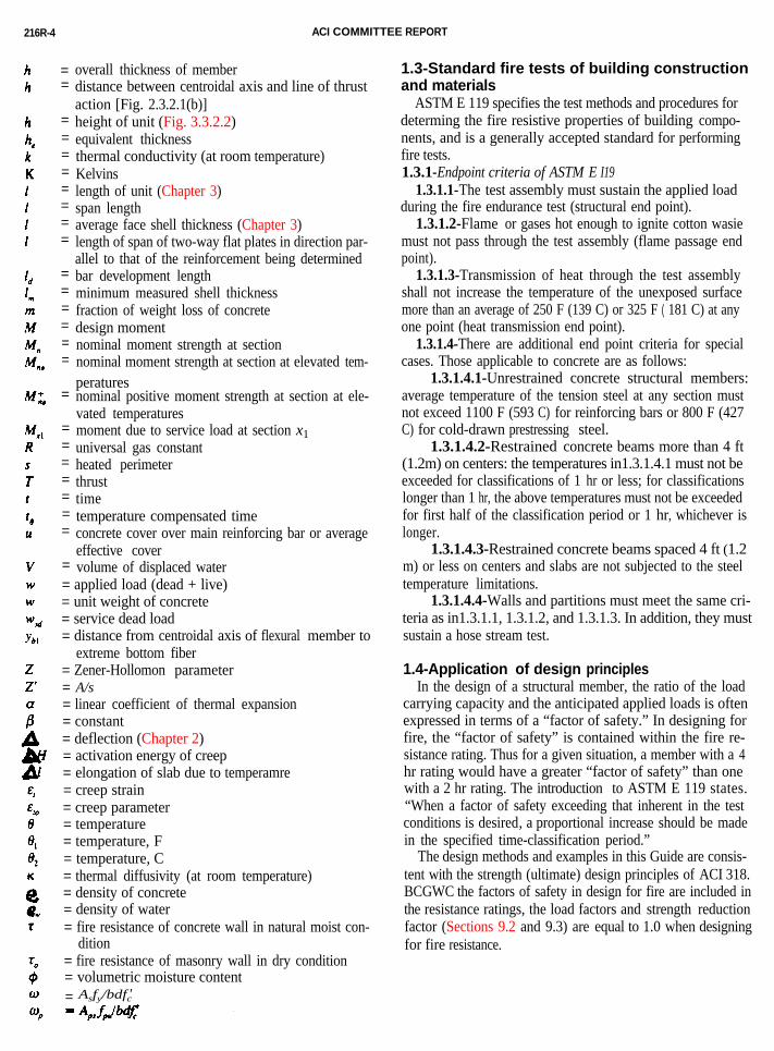
1.3-Standard fire tests of building construction and materials
ASTM E 119 specifies the test methods and procedures fordeterming the fire resistive properties of building compo-nents, and is a generally accepted standard for performingfire tests.1.3.1-Endpoint criteria of ASTM E I19
1.3.1.1-The test assembly must sustain the applied loadduring the fire endurance test (structural end point).
1.3.1.2-Flame or gases hot enough to ignite cotton wasiemust not pass through the test assembly (flame passage endpoint).
1.3.1.3-Transmission of heat through the test assemblyshall not increase the temperature of the unexposed surfacemore than an average of 250 F (139 C) or 325 F ( 181 C) at anyone point (heat transmission end point).
1.3.1.4-There are additional end point criteria for specialcases. Those applicable to concrete are as follows:
1.3.1.4.1-Unrestrained concrete structural members:average temperature of the tension steel at any section mustnot exceed 1100 F (593 C) for reinforcing bars or 800 F (427C) for cold-drawn prestressing steel.
1.3.1.4.2-Restrained concrete beams more than 4 ft(1.2m) on centers: the temperatures in1.3.1.4.1 must not beexceeded for classifications of 1 hr or less; for classificationslonger than 1 hr, the above temperatures must not be exceededfor first half of the classification period or 1 hr, whichever islonger.
1.3.1.4.3-Restrained concrete beams spaced 4 ft (1.2m) or less on centers and slabs are not subjected to the steeltemperature limitations.
1.3.1.4.4-Walls and partitions must meet the same cri-teria as in1.3.1.1, 1.3.1.2, and 1.3.1.3. In addition, they mustsustain a hose stream test.
1.4-Application of design principlesIn the design of a structural member, the ratio of the load
carrying capacity and the anticipated applied loads is oftenexpressed in terms of a “factor of safety.” In designing forfire, the “factor of safety” is contained within the fire re-sistance rating. Thus for a given situation, a member with a 4hr rating would have a greater “factor of safety” than onewith a 2 hr rating. The introduction to ASTM E 119 states.“When a factor of safety exceeding that inherent in the testconditions is desired, a proportional increase should be madein the specified time-classification period.”
The design methods and examples in this Guide are consis-tent with the strength (ultimate) design principles of ACI 318.BCGWC the factors of safety in design for fire are included inthe resistance ratings, the load factors and strength reductionfactor (Sections 9.2 and 9.3) are equal to 1.0 when designingfor fire resistance.
FIRE ENDURANCE OF CONCRETE ELEMENTS 216R-5
CHAPTER 2-FIRE ENDURANCE OFCONCRETE SLABS AND BEAMS
2.1-Simply supported (unrestrained) slabs andbeams
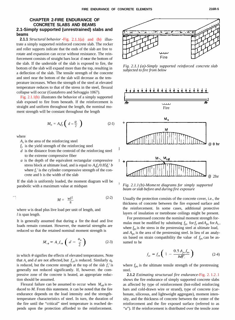
2.1.1 Structural behaviori-Fig. 2.1.1(a) and (b) illus-
w
Fire
Fig. 2.1. 1 (a)-Simply supported reinforced concrete slabsubjected to fire from below
1 1-Fire
I&
@ 0 hr
@ 2hr
Fig. 2.1.1 (b)-Mome nt diagrams for simply supportedbeam or slab before and during fire exposure
trate a simply supported reinforced concrete slab. The rockerand roller supports indicate that the ends of the slab are free torotate and expansion can occur without resistance. The rein-forcement consists of straight bars locat ed near the bottom ofthe slab. If the underside of the slab is exposed to fire, thebottom of the slab will expand more than the top, resulting ina deflection of the slab. The tensile strength of the concreteand steel near the bottom of the slab will decrease as the tem-perature increases. When the strength of the steel at elevatedtemperature reduces to that of the stress in the steel, flexuralcollapse will occur (Gustaferro and Selvaggio 1067).
Fig. 2.1.1(b) illustrates the behavior of a simply supportedslab exposed to fire from beneath. If the reinforcement isstraight and uniform throughout the length, the nominal mo-ment strength will be constant throughout the length
Mn = Asfy ( d - a-2 ) (2-1)
whereAs is the area of the reinforcing steelfyd
a
is the yield strength of the reinforcing steelis the distance from the centroid of the reinforcing steelto the extreme compressive fiberis the depth of the equivalent rectangular compressivestress block at ultimate load, and is equal to Asfy/0.85f ' c b where fc' is the cylinder compressive strength of the con-crete and b is the width of the slab
If the slab is uniformly loaded, the moment diagram will beparabolic with a maximum value at midspan
M = 8-wl2 (2-2)
where w is dead plus live load per unit of length, andl is span length.
It is generally assumed that during a fire the dead and liveloads remain constant. However, the material strengths arereduced so that the retained nominal moment strength is
(2-3)
in which 0- signifies the effects of elevated temperatures. Notethat As and d are not affected, but fy0- is reduced. Similarly a0-
is reduced, but the concrete strength at the top of the slab f 'c isgenerally not reduced significantly. If, however. the com-pressive zone of the concrete is heated, an appropriate reduc-tion should be assumed.
Flexural failure can be assumed to occur when Mn0- is re-duced to M. From this statement. it can be noted that the fireendurance depends on the load intensity and the strength-temperature characteristics of steel. In turn, the duration ofthe fire until the “critical” steel temperature is reached de-pends upon the protection afforded to the reinforcement.
Usually the protection consists of the concrete cover, i.e., thethickness of concrete between the fire exposed surface andthe reinforcement. In some cases, additional protectivelayers of insulation or tnetnbrane ceilings might be present.
For prestressed concrete the nominal moment strength for-mulas must be modified by substituting fps for fy and Aps for As ,where fps is the stress in the prestressing steel at ultimate load,and Aps is the area of the prestressing steel. In lieu of an analy-sis based on strain compatibility the value of fps can be as-sumed to be
(2-4)
where fpu is the ultimate tensile strength of the prestressingsteel.
2.1.2 Estimating structurual fire endurance-Fig. 2. 1.2 .1
shows the fire endurance of simply supported concrete slabsas affected by type of reinforcement (hot-rolled reinforcingbars and cold-drawn wire or strand), type of concrete (car-bonate, siliceous, and lightweight aggregate), moment inten-sity, and the thickness of concrete between the center of thereinforcement and the fire exposed surface (referred to as“u”). If the reinforcement is distributed over the tensile zone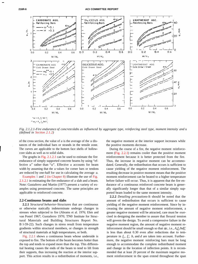
216R-6 ACI COMMITTEE REPORT
2 I I I I I- C A R B O N A T E A G G .
0 I I I I I I
0.0 0.2 0.4 0.6
M / Mn
CA RBONATE AGGCold Drawn Steel
0.3 0.2 0.4 0.6
M / Mn
* uu = As fy/ bd f 'c
** uu p= Aps fpu
/bd f 'c
-SILICEOUS AGG.-Cold Drawn Steel
0.0 0.2 0.4 0.6
M / Mn
I I I I I l L IGHTWEIGHT AGC.
LIGHTWEIGHT AGG
60
0.0 0.2 0.4 0.6
M / Mn
Fig. 2.1.2.1-Fire endurance of concrete slabs as influenced by aggregate type, reinforcing steel type, moment intensity and u(defined in Section 2.. 1 .2)
of the cross section, the value of u is the average of the u dis-tances of the individual bars or strands in the tensile zone.The curves are applicable to the bottom face shells of hollow-core slabs as well as to solid slabs.
The graphs in Fig. 2.1.2.1 can be used to estimate the fireendurance of simply supported concrete beams by using “ef-fective u,,
rather than “u”. Effective u accounts for beamwidth by assuming that the u values for corner bars or tendonsare reduced by one-half for use in calculating the average u.
Examples 1 and 2 (in Chapter 8) illustrate the use of Fig.
2.1.2. 1 in estimating the fire endurance of a slab and a beam.Note: Gustaferro and Martin (1977) present a variety of ex-amples using prestressed concrete. The same principles areapplicable to reinforced concrete.2.2-Continuous beams and slabs2.2.1 Structural behavior-Structures that are continuous
or otherwise statically indeterminate undergo changes instresses when subjected to fire (Abrams et al. 1976; Ehm andvan Postel 1967; Gustaferro 1970; TN0 Institute for Struc-tural Materials and Building Structures Report No.B l-59-22). Such changes in stress result from temperaturegradients within structural members, or changes in strengthof structural materials at high temperatures, or both.
Fig. 2.2.1 shows a continuous beam whose underside is
exposed to fire. The bottom of the beam becomes hotter thanthe top and tends to expand more than the top. This differen-tial heating causes the ends of the beam to tend to lift fromtheir supports, thus increasing the reaction at the interior sup-port. This action results in a redistribution of moments, i.e.,the negative moment at the interior support increases whilethe positive moments decrease.
During the course of a fire, the negative moment reinforce-ment (Fig. 2.2.1) remains cooler than the positive momentreinforcement because it is better protected from the fire.Thus, the increase in negative moment can be accommo-dated. Generally, the redistribution that occurs is sufficient tocause yielding of the negative moment reinforcement. Theresulting decrease in positive moment means that the positivemoment reinforcement can be heated to a higher temperaturebefore failure will occur. Thus, it is apparent that the fire en-durance of a continuous reinforced concrete beam is gener-ally significantly longer than that of a similar simply sup-ported beam loaded to the same moment intensity.
2.2.2 Detailing precautions-It should be noted that theamount of redistribution that occurs is sufficient to causeyielding of the negative moment reinforcement. Since by in-creasing the amount of negative moment reinforcement, agreater negative moment will be attracted, care must be exer-cised in designing the member to assure that flexural tensionwill govern the design. To avoid a compressive failure in thenegative moment region, the amount of negative moment re-inforcement should be small enough so that uu , i.e., Asfy/bdfc'is less than about 0.30 even after reductions due to tem-perature in fy , fc', b, and d are taken into account. Further-more, the negative moment reinforcing bars must be longenough to accommodate the complete redistributed momentand change in the location of inflection points. It is recom-mended that at least 20 percent of the maximum negative mo-ment reinforcement in the span extend throughout the span
FIRE ENDURANCE OF CONCRETE ELEMENTS 216R-7
Fire Fire
@ 3 h r
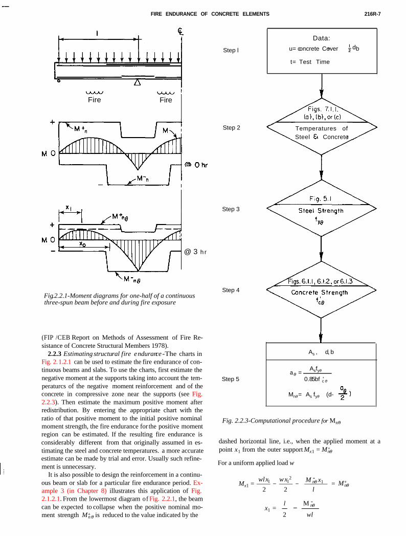
Fig.2.2.1-Moment diagrams for one-half of a continuousthree-spun beam before and during fire exposure
(FIP /CEB Report on Methods of Assessment of Fire Re-sistance of Concrete Structural Members 1978).
2.2.3 Estimating structural fire endurance-The charts inFig. 2. 1.2.1 can be used to estimate the fire endurance of con-tinuous beams and slabs. To use the charts, first estimate thenegative moment at the supports taking into account the tem-peraturcs of the negative moment reinforcement and of theconcrete in compressive zone near the supports (see Fig.2.2.3). Then estimate the maximum positive moment after
Step l
Data:
u= concrete Cover + l-2 db
t= Test Time
Step 2 Temperatures ofSteel EC Concrete
Step 3
Step 4
Step 5
t
As , d, b
a0- =Asfy0-
0.85bf 'c 0-
Mn0- = As fy0- (d-
Fig. 2.2.3-Computational procedure for Mn0-
redistribution. By entering the appropriate chart with theratio of that positive moment to the initial positive nominalmoment strength, the fire endurance for the positive momentregion can be estimated. If the resulting fire endurance isconsiderably different from that originally assumed in es-timating the steel and concrete temperatures. a more accurateestimate can be made by trial and error. Usually such refine-ment is unnecessary.
It is also possible to design the reinforcement in a continu-ous beam or slab for a particular fire endurance period. Ex-ample 3 (in Chapter 8) illustrates this application of Fig.
2.1.2.1. From the lowermost diagram of Fig. 2.2.1, the beamcan be expected to collapse when the positive nominal mo-ment strength M+n 0- is reduced to the value indicated by thedashed horizontal line, i.e., when the applied moment at apoint x1 from the outer support Mx1 = M+
n 0-
For a uniform applied load w
wlx1 wx12 M -
n 0- x1Mx1 =_ - _ --=
2 2 lM+
n 0-
x1 = - - -l M -
n 0-
2 wl
216R-8
and
WI?M, = -- wl? v w+n*
-2 WI?
Also
X,, = zr,
For a symmetrical interior bay
Xl = L/2
WPM,, = 8 -M,,,
or
M,= +&
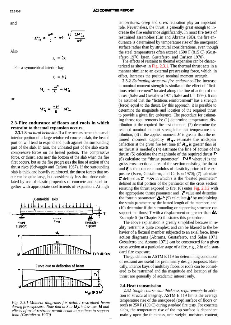
2.3-Fire endurance of floors and roofs in whichrestraint to thermal expansion occurs
2.3.1 Structural behavior-If a fire occurs beneath a smallinterior portion of a large reinforced concrete slab, the heatedportion will tend to expand and push against the surroundingpart of the slab. In turn, the unheated part of the slab exertscompressive forces on the heated portion. The compressiveforce, or thrust, acts near the bottom of the slab when the firefirst occurs, but as the fire progresses the line of action of thethrust rises (Selvaggio and Carlson 1967). If the surroundingslab is thick and heavily reinforced. the thrust forces that oc-cur can be quite large, but considerably less than those calcu-lated by use of elastic properties of concrete and steel to-gether with appropriate coefficients of expansion. At high
,Centroidal axis
1-
moveablesupport support
Curve due to deflection of beam+i - - I 4
Te
M AFig. 2.3.1-Moment diagrams for axially restrained beamduring fire exposure. Note that at 3 hr M,, is less than M andeffects of axial restraint permit beam to continue to supportload (Gustaferro 1970)
-
temperatures, creep and stress relaxation play an importantrole. Nevertheless, the thrust is generally great enough to in-crease the fire endurance significantly. In most fire tests ofrestrained assemblies (Lin and Abrams 1983), the fire en-durance is determined by temperature rise of the unexposedsurface rather than by structural considerations, even thoughthe steel temperatures often exceed 1500 F (815 C) (Gust-aferro 1970; Issen, Gustaferro, and Carlson 1970).
The effects of restraint to thermal expansion can be charac-terized as shown in Fig. 2.3.1. The thermal thrust acts in amanner similar to an external prestressing force, which, ineffect, increases the positive nominal moment strength.
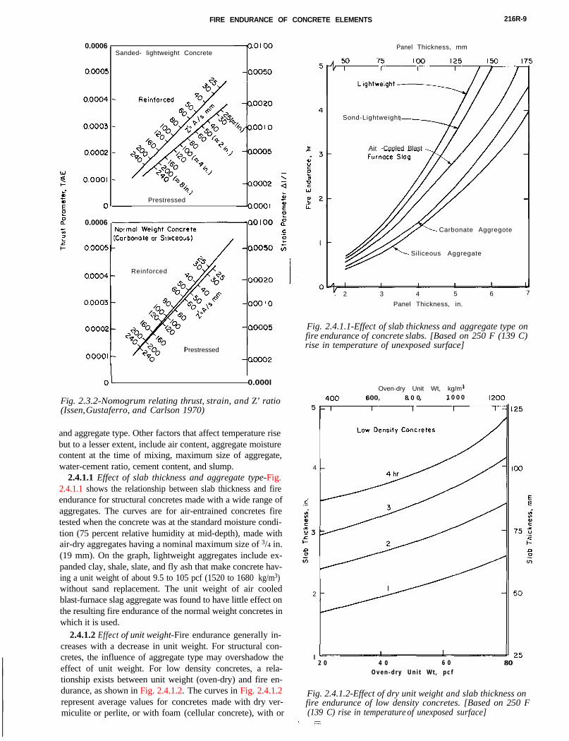
2.3.2 Estimating structural fire endurance-The increasein nominal moment strength is similar to the effect of “ficti-tious reinforcement” located along the line of action of thethrust (Salse and Gustaferro 1971; Salse and Lin 1976). It canbe assumed that the “fictitious reinforcement” has a strength(force) equal to the thrust. By this approach, it is possible todetermine the magnitude and location of the required thrustto provide a given fire endurance. The procedure for estimat-ing thrust requirements is: (1) determine temperature dis-tribution at the required fire test duration; (2) determine theretained nominal moment strength for that temperature dis-tribution; (3) if the applied moment M is greater than the re-tained moment capacity M,,, estimate the midspandeflection at the given fire test time (if M,, is greater than Mno thrust is needed); (4) estimate the line of action of thethrust; (5) calculate the magnitude of the required thrust T;(6) calculate the “thrust parameter" TIAE where A is thegross cross-sectional area of the section resisting the thrustand E is the concrete modulus of elasticity prior to fire ex-posure (Issen, Gustaferro, and Carlson 1970); (7) calculate2’ defined as 2’ = A/s in which s is the “heated perimeter”defined as that portion of the perimeter of the cross sectionresisting the thrust exposed to fire; (8) enter Fig. 2.3.2 with
the appropriate thrust parameter and 2’ value and determinethe “strain parameter” &l; (9) calculate &I by multiplyingthe strain parameter by the heated length of the member; and(10) determine if the surrounding or supporting structure cansupport the thrust T with a displacement no greater than 4.Example 5 (in Chapter 8) illustrates this procedure.The above explanation is greatly simplified because in re-ality restraint is quite complex, and can be likened to the be-havior of a flexural member subjected to an axial force. Inter-action diagrams (Abrams, Gustaferro, and Salse 1971;Gustaferro and Abrams 1971) can be constructed for a givencross section at a particular stage of a fire, e.g., 2 hr of a stan-dard fire exposure.
The guidelines in ASTM E 119 for determining conditionsof restraint are useful for preliminary design purposes. Basi-cally, interior bays of multibay floors or roofs can be consid-ered to be restrained and the magnitude and location of thethrust are generally of academic interest only.
2.4-Heat transmission2.4.1 Single course slab thickness requirements-In addi-
tion to structural integrity, ASTM E 119 limits the averagetemperature rise of the unexposed (top) surface of floors orroofs to 250 F (139 C) during standard fire tests. For concreteslabs, the temperature rise of the top surface is dependentmainly upon the thickness, unit weight, moisture content,
FIRE ENDURANCE OF CONCRETE ELEMENTS 216R-9
0.0006
0.0006
Sanded- lightweight Concrete
‘,Prestressed
Reinforced
Prestressed
OL 0.000l
Fig. 2.3.2-Nomogrum relating thrust, strain, and Z’ ratio(Issen, Gustaferro, and Carlson 1970)
and aggregate type. Other factors that affect temperature risebut to a lesser extent, include air content, aggregate moisturecontent at the time of mixing, maximum size of aggregate,water-cement ratio, cement content, and slump.
2.4.1.1 Effect of slab thickness and aggregate type-Fig.2.4.1.1 shows the relationship between slab thickness and fire
Panel Thickness, mm
Sond-Lightweight
Air -Cooled Blast
Carbonate Aggregote
Siliceous Aggregate
. 2 3 4 5 6 7
Panel Thickness, in.
Fig. 2.4.1.1-Effect of slab thickness and aggregate type onfire endurance of concrete slabs. [Based on 250 F (139 C)rise in temperature of unexposed surface]
endurance for structural concretes made with a wide range ofaggregates. The curves are for air-entrained concretes firetested when the concrete was at the standard moisture condi-tion (75 percent relative humidity at mid-depth), made withair-dry aggregates having a nominal maximum size of 3/4 in.(19 mm). On the graph, lightweight aggregates include ex-panded clay, shale, slate, and fly ash that make concrete hav-ing a unit weight of about 9.5 to 105 pcf (1520 to 1680 kg/m3)without sand replacement. The unit weight of air cooledblast-furnace slag aggregate was found to have little effect onthe resulting fire endurance of the normal weight concretes inwhich it is used.
2.4.1.2 Effect of unit weight-Fire endurance generally in-creases with a decrease in unit weight. For structural con-cretes, the influence of aggregate type may overshadow theeffect of unit weight. For low density concretes, a rela-tionship exists between unit weight (oven-dry) and fire en-durance, as shown in Fig. 2.4.1.2. The curves in Fig. 2.4.1.2
Oven-dry Unit Wt, kg/m3
600 8 0 0 1 0 0 0
4
2
l2 0 4 0 6 0 80
O v e n - d r y U n i t W t , p c f
Fig. 2.4.1.2-Effect of dry unit weight and slab thickness onfire endurunce of low density concretes. [Based on 250 F
(139 C) rise in temperature of unexposed surface]
represent average values for concretes made with dry ver-miculite or perlite, or with foam (cellular concrete), with or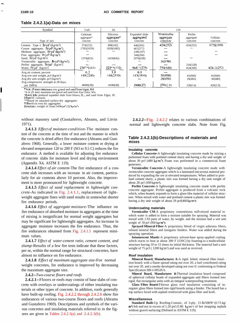
216R-10 ACI COMMITTEE REPORT
Table 2.4.2.1(a)-Data on mixes
Symbol
Type of mix
Cement. Type I. lbiyd’ (kg/m’)Coarse aggregate, Ib/yd’ (kg/m7)Medium aggregate, Ib/yd’ (kgirnj)Fine aggregate, lb&d’ (kg/m’)Sand, Ib/yd’ (hg/mi)Vermiculite aggregate, Ib/yd’ (kg/m’)Perlite aggregate, Ib/yd’ (kg/m3)Water, Ih/yd’ (kg/m3)
Avg air content, percentAvg wet unit weight, pcf (kg/m3)Avg dry unit weight, pcf (kg/m3)Avg compressive strength at 28 days,
psi (MPa)
Carb
Carbonateaggregate*
concrete
374(222)1785( 1059)
--
1374(815)-
Sil LW
Siliceousaggregatei-
concrete
408(242)1828( 1085)
-
1419(842)
4000(28) i 4100(28)
7% in. (9 mm) maximum size gravel and sand from Eau Claire, Wis.$Rotary-kiln produced expanded shale from Ottawa, Ill., ,and sand from Elgin, Ill.5Type Ill cement.**Based on saturated surface-dry aggregatesttBascd on oven dry aggregatesMncludes weight of foam 54 Ib/yd’ (32 kg/m’)
Expanded shaleaggregate:
concrete
446(265)467(277)248(147)344(204)1076(638)-
Perliteaggregateconcrete
424(252)-
-
Cellularconcrete
6736(3991
--
216(128)454(269) 424$$(252)
41(660) 41(660)29(465) 30(480)
230( 1 .6) 420(2.9)
without masonry sand (Gustaferro, Abrams, and Litvin1971).
2.4.1.3 Effect of moisture condition-The moisture con-tent of the concrete at the time of test and the manner in whichthe concrete is dried affect fire endurance (Abrams and Gust-aferro 1968). Generally, a lower moisture content or drying atelevated temperature 120 to 200 F (SO to 9.5 C) reduces the fireendurance. A method is available for adjusting fire enduranceof concrete slabs for moisture level and drying environment(Appendix X4, ASTM E 119).
2.4.1.4 Effect of air content-The fire endurance of a con-crete slab increases with an increase in air content, particu-larly for air contents above 10 percent. Also, the improve-ment is more pronounced for lightweight concrete.
2.4.1.5 Effect of sand replacement in lightweight con-crete-As indicated in Fig. 2.4.1.1, replacement of light-weight aggregate fines with sand results in somewhat shorterfire endurance periods.
2.4.1.6 Effect of aggregate moisture-The influence onfire endurance of absorbed moisture in aggregates at the timeof mixing is insignificant for normal weight aggregates butmay be significant for lightweight aggregates. An increase inaggregate moisture increases the fire endurance. Thus, thefire endurances obtained from Fig. 2.4.1.1 represent mini-mum values.
2.4.1.7 Effect of water-cement ratio, cement content, andslump-Results of a few fire tests indicate that these factors,per se, within the normal range for structural concretes, havealmost no influence on fire endurance.
2.4.1.8 Effect of maximum aggregate size-For normalweight concretes, fire endurance is improved by decreasingthe maximum aggregate size.
2.4.2-Two-course floors and roofs2.4.2.1-Floors or roofs may consist of base slabs of con-
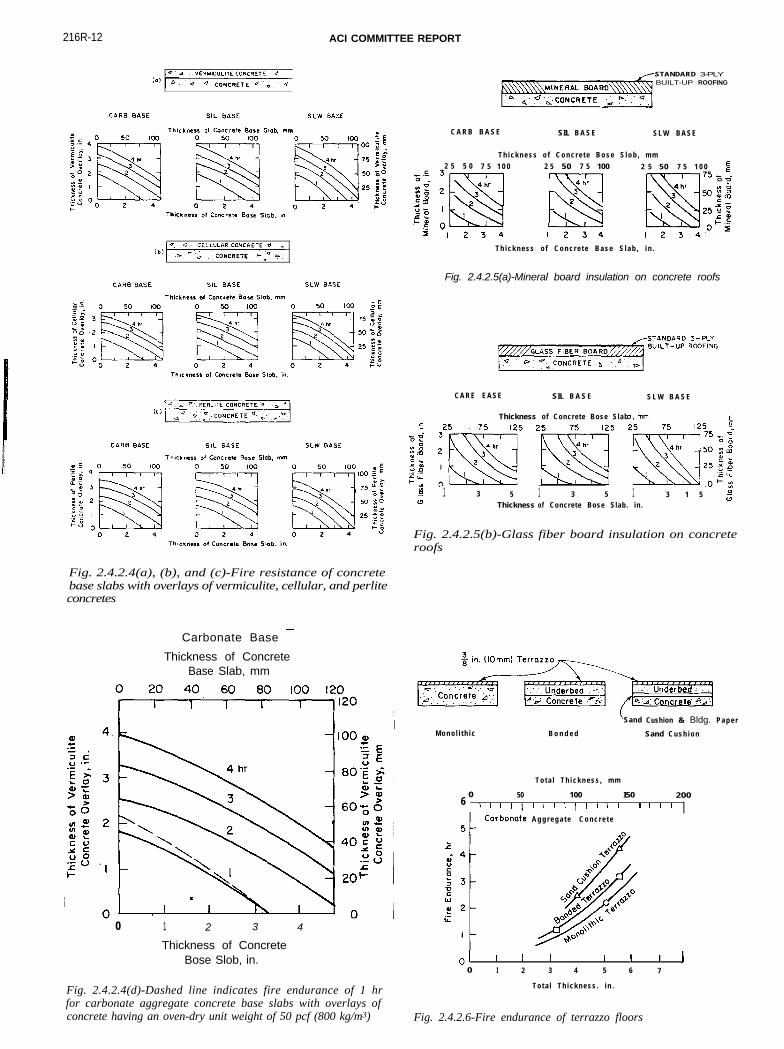
crete with overlays or undercoatings of either insulating ma-terials or other types of concrete. In addition, roofs generallyhave built-up roofing. Fig. 2.4.2.2 through 2.4.2.6 show fire
endurances of various two-course floors and roofs (Abramsand Gustaferro 1969). Descriptions and symbols of the vari-ous concretes and insulating materials referred to in the fig-ures are given in Tables 2.4.2.1(a) and 2.4.2.1(b).Table 2.4.2.1(b)-Descriptions of materials andmixes
Insulating concreteCellular Concrete-A lightweight insulating concrete made by mixing a
preformed foam with portland cement slurry and having a dry unit weight ofabout 30 pcf (480 kg/m?). Foam was preformed in a commercial foamgenerator.
Vermiculite Concrete-A lightweight insulating concrete made withvermiculite concrete aggregate which is a laminated micaceous material pro-duced by expanding the ore at elevated temperatures. When added to port-land cement slurry, a plastic mix was formed having a dry unit weight ofabout 28 pcf (450 kgimj).
Perlite Concrete-A lightweight insulating concrete made with perliteconcrete aggregate. Perlite aggregate is produced from a volcanic rockwhich, when heated, expands to form a glass-like material of cellular struc-ture. When mixed with water and portland cement a plastic mix was formedhaving a dry unit weight of about 29 pcf(460 kg/m3).
Undercoating materialsVermiculite CM-A proprietary cementitious mill-mixed material to
which water is added to form a mixture suitable for spraying. Material wasmixed with 1.93 parts of water, by weight. and the mixture had a wet unitweight of 59 pcf (950 kg/m’).
Sprayed Mineral Fiber-A proprietary blend of virgin asbestos fibers,relined mineral fibers and inorganic binders. Water was added during thespraying operation.
Intumescent Mastic-A proprietary solvent-base spray-applied coatingwhich reacts to heat at about 300 F ( 150 C) by foaming to a multicellularstructure having 10 to 15 times its initial thickness. The material had a unitweight of 75 pcf ( 1200 kg/m3) and was used as received.
Roof insulationMineral Board, Manufacturer A-A rigid. felted. mineral fiber insul-
tion board; with a flame spread rating not over 20, a fuel contributed ratingnot over 20. and a smoke developed rating not over 0: conforming to FederalSpecification HH-I-00526 b.
Mineral Board, Manufacturer B-Thermal insulation board composedof spherical cellular beads of expanded aggregate and fibers formed intorigid, flat rectangular units with an integral waterproofing treatment.
Glass Fiber Board-Fibrous glass roof insulation consisting of in-organic glass fibers formed into rigid boards using a binder. The board has atop surface faced with asphalt reinforced with glass fiber and kraft.
MiscellaneousStandard Built-Up Roofing-Consist:, of 3-ply, 15 lb/100 ft’ (0.73 kg/
m*) felt and not in excess of 1.20 psf (5.86 kg/m’) of hot mopping asphaltwithout gravel surfacing (Defined in ASTM E 119).
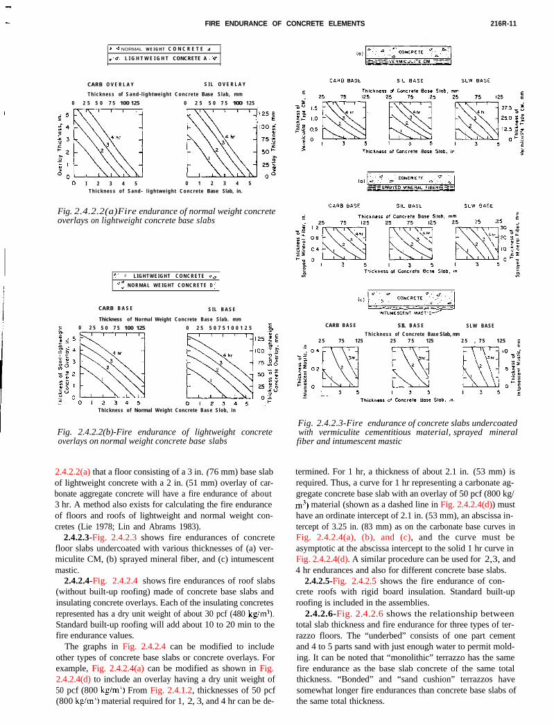
2.4.2.2-Fig. 2.4.2.2 relates to various combinations ofnormal and lightweight concrete slabs. Note from Fig.
FIRE ENDURANCE OF CONCRETE ELEMENTS 216R-11
I
h 4 NORMAL W E I G H T C O N C R E T E d
v ‘4. L I G H T W E I G H T CONCRETE A .‘Q
CARB O V E R L A Y S I L O V E R L A Y
T h i c k n e s s of S a n d - l i g h t w e i g h t C o n c r e t e Base Slab, mm
0 2 5 5 0 7 5 100 125 0 2 5 5 0 7 5 1000 125
IO I 2 3 4 5 0 1 2 3 4 5
T h i c k n e s s o f S a n d - l i g h t w e i g h t C o n c r e t e Base Slab, in.
Fig. 2.4.2.2(a)Fire endurance of normal weight concreteoverlays on lightweight concrete base slabs
f. d L I G H T W E I G H T C O N C R E T E .J q
a ; N O R M A L W E I G H T C O N C R E T E D <.
CARB B A S E S I L B A S E
Thickness of Normal Weight Concrete Base Slab. mm
z 0 2 5 5 0 7 5 100 125 0 2 5 5 0 7 5 1 0 0 1 2 5 5
Thickness of Normal Weight Concrete Base Slob, in
Fig. 2.4.2.2(b)-Fire endurance of lightweight concreteoverlays on normal weight concrete base slabs
CARB B A S E SIL B A S E SLW BASE
T h i c k n e s s of Concrete Base Slab, mm2 5 7 5 125 2 5 7 5 125 2 5 , 7 5 125 5
Fig. 2.4.2.3-Fire endurance of concrete slabs undercoatedwith vermiculite cementitious material, sprayed mineralfiber and intumescent mastic
2.4.2.2(a) that a floor consisting of a 3 in. (76 mm) base slabof lightweight concrete with a 2 in. (51 mm) overlay of car-bonate aggregate concrete will have a fire endurance of about3 hr. A method also exists for calculating the fire enduranceof floors and roofs of lightweight and normal weight con-cretes (Lie 1978; Lin and Abrams 1983).
2.4.2.3-Fig. 2.4.2.3 shows fire endurances of concretefloor slabs undercoated with various thicknesses of (a) ver-miculite CM, (b) sprayed mineral fiber, and (c) intumescentmastic.
2.4.2.4-Fig. 2.4.2.4 shows fire endurances of roof slabs(without built-up roofing) made of concrete base slabs andinsulating concrete overlays. Each of the insulating concretesrepresented has a dry unit weight of about 30 pcf (480 kg/m”).Standard built-up roofing will add about 10 to 20 min to thefire endurance values.
The graphs in Fig. 2.4.2.4 can be modified to includeother types of concrete base slabs or concrete overlays. Forexample, Fig. 2.4.2.4(a) can be modified as shown in Fig.2.4.2.4(d) to include an overlay having a dry unit weight of50 pcf (800 kg/m’) From Fig. 2.4.1.2, thicknesses of 50 pcf(800 kg/mJ) material required for 1, 2, 3, and 4 hr can be de-
termined. For 1 hr, a thickness of about 2.1 in. (53 mm) isrequired. Thus, a curve for 1 hr representing a carbonate ag-gregate concrete base slab with an overlay of 50 pcf (800 kg/m’) material (shown as a dashed line in Fig. 2.4.2.4(d)) musthave an ordinate intercept of 2.1 in. (53 mm), an abscissa in-tercept of 3.25 in. (83 mm) as on the carbonate base curves inFig. 2.4.2.4(a), (b), and (c), and the curve must beasymptotic at the abscissa intercept to the solid 1 hr curve inFig. 2.4.2.4(d). A similar procedure can be used for 2,3, and4 hr endurances and also for different concrete base slabs.
2.4.2.5-Fig. 2.4.2.5 shows the fire endurance of con-crete roofs with rigid board insulation. Standard built-uproofing is included in the assemblies.
2.4.2.6-Fig. 2.4.2.6 shows the relationship betweentotal slab thickness and fire endurance for three types of ter-razzo floors. The “underbed” consists of one part cementand 4 to 5 parts sand with just enough water to permit mold-ing. It can be noted that “monolithic” terrazzo has the samefire endurance as the base slab concrete of the same totalthickness. “Bonded” and “sand cushion” terrazzos havesomewhat longer fire endurances than concrete base slabs ofthe same total thickness.
216R-12 ACI COMMITTEE REPORT
Fig. 2.4.2.4(a), (b), and (c)-Fire resistance of concretebase slabs with overlays of vermiculite, cellular, and perliteconcretes
Carbonate Base -
Thickness of ConcreteBase Slab, mm
0 1 2 3 4
Thickness of ConcreteBose Slob, in.
Fig. 2.4.2.4(d)-Dashed line indicates fire endurance of 1 hrfor carbonate aggregate concrete base slabs with overlays ofconcrete having an oven-dry unit weight of 50 pcf (800 kg/m3)
STANDARD 3-PLYBUILT-UP ROOFING
C A R B B A S E SIL B A S E S L W B A S E
T h i c k n e s s o f C o n c r e t e B o s e S l o b , m m
2 5 5 0 7 5 1 0 0 2 5 500 7 5 100 2 5 50I 7 5 1 0 0 g
T h i c k n e s s o f C o n c r e t e B a s e S l a b , i n .
Fig. 2.4.2.5(a)-Mineral board insulation on concrete roofs
C A R E E A S E SIL B A S E S L W B A S E
Thickness of Concrete Bose Slab, mm
i? ;m 2H5 2$+&-J;;$
-0 1 3 5 1 3 5 1 3 1 50
yThickness of Concrete Bose Slab. in.
Fig. 2.4.2.5(b)-Glass fiber board insulation on concreteroofs
M o n o l i t h i c B o n d e d
Sandd Cushion & Bldg. P a p e r
Sand C u s h i o n
T o t a l T h i c k n e s s , m m
0 50 100 I50 2006 ,,I ,,,,,,,,,,, I,,,
A g g r e g a t e C o n c r e t e
J I I I I I 1 I 10 I 2 3 4 5 6 7
T o t a l T h i c k n e s s . i n .
Fig. 2.4.2.6-Fire endurance of terrazzo floors
FIRE ENDURANCE OF CONCRETE ELEMENTS 216R-13
CHAPTER 3-FIRE ENDURANCE OF WALLS
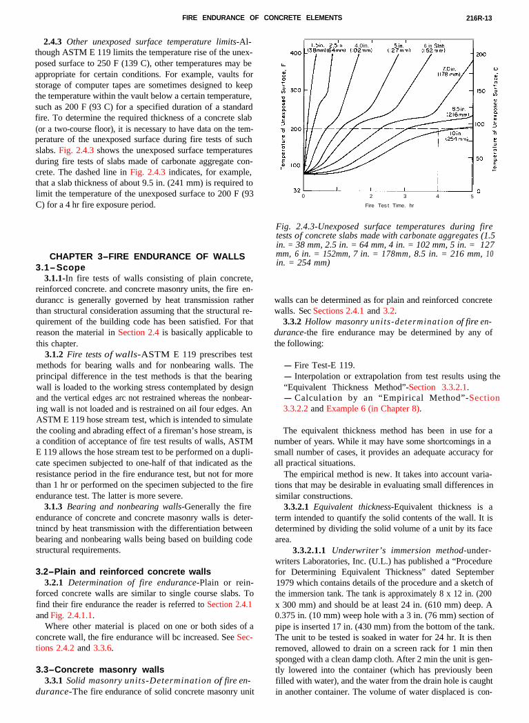
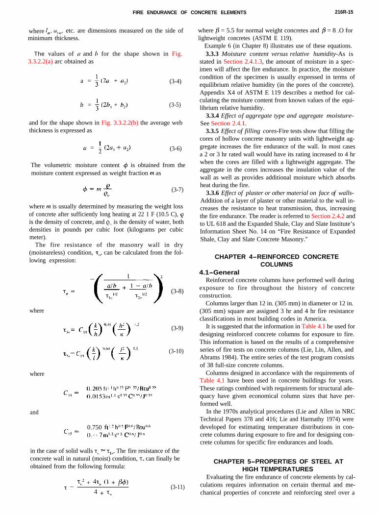
2.4.3 Other unexposed surface temperature limits-Al-though ASTM E 119 limits the temperature rise of the unex-posed surface to 250 F (139 C), other temperatures may beappropriate for certain conditions. For example, vaults forstorage of computer tapes are sometimes designed to keepthe temperature within the vault below a certain temperature,such as 200 F (93 C) for a specified duration of a standardfire. To determine the required thickness of a concrete slab(or a two-course floor), it is necessary to have data on the tem-perature of the unexposed surface during fire tests of suchslabs. Fig. 2.4.3 shows the unexposed surface temperatures
1.5in. 2.51n. 4.0in. ’ 5in.’ 6 in Slbb
32-100 2 3 4 5
Fire Tes t Time. hr
Fig. 2.4.3-Unexposed surface temperatures during firetests of concrete slabs made with carbonate aggregates (1.5in. = 38 mm, 2.5 in. = 64 mm, 4 in. = 102 mm, 5 in. = 127mm, 6 in. = 152mm, 7 in. = 178mm, 8.5 in. = 216 mm, 10in. = 254 mm)
during fire tests of slabs made of carbonate aggregate con-crete. The dashed line in Fig. 2.4.3 indicates, for example,that a slab thickness of about 9.5 in. (241 mm) is required tolimit the temperature of the unexposed surface to 200 F (93C) for a 4 hr fire exposure period.
3.1-Scope3.1.1-In fire tests of walls consisting of plain concrete,
reinforced concrete. and concrete masonry units, the fire en-durancc is generally governed by heat transmission ratherthan structural consideration assuming that the structural re-quirement of the building code has been satisfied. For thatreason the material in Section 2.4 is basically applicable tothis chapter.
3.1.2 Fire tests of walls-ASTM E 119 prescribes testmethods for bearing walls and for nonbearing walls. Theprincipal difference in the test methods is that the bearingwall is loaded to the working stress contemplated by designand the vertical edges arc not restrained whereas the nonbear-ing wall is not loaded and is restrained on ail four edges. AnASTM E 119 hose stream test, which is intended to simulatethe cooling and abrading effect of a fireman’s hose stream, isa condition of acceptance of fire test results of walls, ASTME 119 allows the hose stream test to be performed on a dupli-cate specimen subjected to one-half of that indicated as theresistance period in the fire endurance test, but not for morethan 1 hr or performed on the specimen subjected to the fireendurance test. The latter is more severe.
3.1.3 Bearing and nonbearing walls-Generally the fireendurance of concrete and concrete masonry walls is deter-tnincd by heat transmission with the differentiation betweenbearing and nonbearing walls being based on building codestructural requirements.
3.2-Plain and reinforced concrete walls3.2.1 Determination of fire endurance-Plain or rein-
forced concrete walls are similar to single course slabs. Tofind their fire endurance the reader is referred to Section 2.4.1and Fig. 2.4.1.1.
Where other material is placed on one or both sides of aconcrete wall, the fire endurance will bc increased. See Sec-tions 2.4.2 and 3.3.6.
3.3-Concrete masonry walls3.3.1 Solid masonry units-Determination of fire en-
durance-The fire endurance of solid concrete masonry unit
walls can be determined as for plain and reinforced concretewalls. Sec Sections 2.4.1 and 3.2.
3.3.2 Hollow masonry uni ts -determinat ion of fire en-durance-the fire endurance may be determined by any ofthe following:
- Fire Test-E 119.- Interpolation or extrapolation from test results using the“Equivalent Thickness Method”-Section 3.3.2.1.
3.3.2.1 Equivalent thickness-Equivalent thickness is aterm intended to quantify the solid contents of the wall. It isdetermined by dividing the solid volume of a unit by its facearea.
- Calculation by an “Empirical Method”-Section3.3.2.2 and Example 6 (in Chapter 8).
The equivalent thickness method has been in use for anumber of years. While it may have some shortcomings in asmall number of cases, it provides an adequate accuracy forall practical situations.
The empirical method is new. It takes into account varia-tions that may be desirable in evaluating small differences insimilar constructions.
3.3.2.1.1 Underwriter’s immersion method-under-writers Laboratories, Inc. (U.L.) has published a “Procedurefor Determining Equivalent Thickness” dated September1979 which contains details of the procedure and a sketch ofthe immersion tank. The tank is approximately 8 x 12 in. (200x 300 mm) and should be at least 24 in. (610 mm) deep. A0.375 in. (10 mm) weep hole with a 3 in. (76 mm) section ofpipe is inserted 17 in. (430 mm) from the bottom of the tank.The unit to be tested is soaked in water for 24 hr. It is thenremoved, allowed to drain on a screen rack for 1 min thensponged with a clean damp cloth. After 2 min the unit is gen-tly lowered into the container (which has previously beenfilled with water), and the water from the drain hole is caughtin another container. The volume of water displaced is con-
216R-14 ACI COMMITTEE REPORT
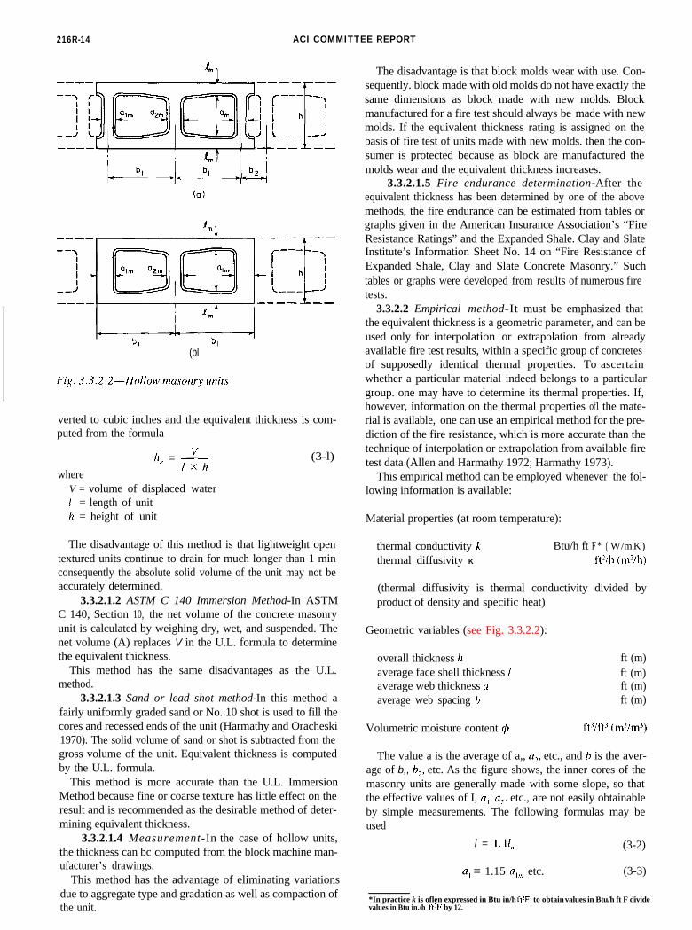
(bl
3.3.2.2 Empirical method-It must be emphasized thatthe equivalent thickness is a geometric parameter, and can beused only for interpolation or extrapolation from alreadyavailable fire test results, within a specific group of concretesof supposedly identical thermal properties. To ascertainwhether a particular material indeed belongs to a particulargroup. one may have to determine its thermal properties. If,however, information on the thermal properties of1 the mate-rial is available, one can use an empirical method for the pre-diction of the fire resistance, which is more accurate than thetechnique of interpolation or extrapolation from available firetest data (Allen and Harmathy 1972; Harmathy 1973).
This empirical method can be employed whenever the fol-lowing information is available:
Material properties (at room temperature):
thermal conductivity li Btu/h ft F * ( W/mK)thermal diffusivity K ft?/h (m’ih)
(thermal diffusivity is thermal conductivity divided byproduct of density and specific heat)
Geometric variables (see Fig. 3.3.2.2):
overall thickness 11 ft (m)average face shell thickness 1 ft (m)average web thickness o ft (m)average web spacing 17 ft (m)
Volumetric moisture content I$ ft’/ft3 (m’/m”)
The value a is the average of a,, u?, etc., and h is the aver-age of b,, b?, etc. As the figure shows, the inner cores of themasonry units are generally made with some slope, so thatthe effective values of I, u,, a?, etc., are not easily obtainableby simple measurements. The following formulas may beused
l = I. I(,, (3-2)
a, = 1.15 cl,,,> etc. (3-3)
*In practice k is oflen expressed in Btu in/h fPF; to obtain values in Btu/h ft F dividevalues in Btu in./h ft’F by 12.
verted to cubic inches and the equivalent thickness is com-puted from the formula
where
h, = vixh
(3-l)
V = volume of displaced water1 = length of unith = height of unit
The disadvantage of this method is that lightweight opentextured units continue to drain for much longer than 1 minconsequently the absolute solid volume of the unit may not beaccurately determined.
3.3.2.1.2 ASTM C 140 Immersion Method-In ASTMC 140, Section 10, the net volume of the concrete masonryunit is calculated by weighing dry, wet, and suspended. Thenet volume (A) replaces V in the U.L. formula to determinethe equivalent thickness.
This method has the same disadvantages as the U.L.method.
3.3.2.1.3 Sand or lead shot method-In this method afairly uniformly graded sand or No. 10 shot is used to fill thecores and recessed ends of the unit (Harmathy and Oracheski1970). The solid volume of sand or shot is subtracted from thegross volume of the unit. Equivalent thickness is computedby the U.L. formula.
This method is more accurate than the U.L. ImmersionMethod because fine or coarse texture has little effect on theresult and is recommended as the desirable method of deter-mining equivalent thickness.
3.3.2.1.4 Measurement-In the case of hollow units,the thickness can bc computed from the block machine man-ufacturer’s drawings.
This method has the advantage of eliminating variationsdue to aggregate type and gradation as well as compaction ofthe unit.
The disadvantage is that block molds wear with use. Con-sequently. block made with old molds do not have exactly thesame dimensions as block made with new molds. Blockmanufactured for a fire test should always be made with newmolds. If the equivalent thickness rating is assigned on thebasis of fire test of units made with new molds. then the con-sumer is protected because as block are manufactured themolds wear and the equivalent thickness increases.
3.3.2.1.5 Fire endurance determination-After theequivalent thickness has been determined by one of the abovemethods, the fire endurance can be estimated from tables orgraphs given in the American Insurance Association’s “FireResistance Ratings” and the Expanded Shale. Clay and SlateInstitute’s Information Sheet No. 14 on “Fire Resistance ofExpanded Shale, Clay and Slate Concrete Masonry.” Suchtables or graphs were developed from results of numerous firetests.
FIRE ENDURANCE OF CONCRETE ELEMENTS 216R-15
where I,),’ (I,,,,, etc. are dimensions measured on the side ofminimum thickness.
The values of CI and b for the shape shown in Fig.3.3.2.2(a) arc obtained as
a = + (2u, + U?) (3-4)
b = + (2h, + b2) (3-5)
and for the shape shown in Fig. 3.3.2.2(b) the average webthickness is expressed as
L1 = ; (2a, + NJ (3-6)
The volumetric moisture content $ is obtained from themoisture content expressed as weight fraction m as
(3-7)
where 171 is usually determined by measuring the weight lossof concrete after sufficiently long heating at 22 1 F (10.5 C), Qis the density of concrete, and Q,, is the density of water, bothdensities in pounds per cubic foot (kilograms per cubicmeter).
The fire resistance of the masonry wall in dry(moistureless) condition, ‘c,,, can be calculated from the fol-lowing expression:
t,,= (-$+‘yJ (3-8)
where
‘c,,, = c,4(;)055(g ‘.?
T?,, = c,, (;) “.“‘( $) I.’
(3-9)
(3-10)
where
c 0,205 ftl.1 h” 3.5 fiV 55/Btu0."'=1 4 0.0153m’.1 s035C055/J05S
and
C 0.750 ft’-” h” 5 F”h/Btu”.”=I5 0, , , 7 ml.2 +I 5 CO.“/ JO.6
in the case of solid walls T(, s T,“. The fire resistance of theconcrete wall in natural (moist) condition, T, can finally beobtained from the following formula:
-$,I + 4t,, (1 + /3(b)T=
4 + T,,(3-11)
where fi = 5.5 for normal weight concretes and /3 = 8 .O forlightweight concretes (ASTM E 119).
Example 6 (in Chapter 8) illustrates use of these equations.3.3.3 Moisture content versus relative humidity-As is
stated in Section 2.4.1.3, the amount of moisture in a spec-imen will affect the fire endurance. In practice, the moisturecondition of the specimen is usually expressed in terms ofequilibrium relative humidity (in the pores of the concrete).Appendix X4 of ASTM E 119 describes a method for cal-culating the moisture content from known values of the equi-librium relative humidity.
3.3.4 Effect of aggregate type and aggregate moisture-See Section 2.4.1.
3.3.5 Effect of filling cores-Fire tests show that filling thecores of hollow concrete masonry units with lightweight ag-gregate increases the fire endurance of the wall. In most casesa 2 or 3 hr rated wall would have its rating increased to 4 hrwhen the cores are filled with a lightweight aggregate. Theaggregate in the cores increases the insulation value of thewall as well as provides additional moisture which absorbsheat during the fire.
3.3.6 Effect of plaster or other material on face of walls-Addition of a layer of plaster or other material to the wall in-creases the resistance to heat transmission, thus, increasingthe fire endurance. The reader is referred to Section 2.4.2 andto UL 618 and the Expanded Shale, Clay and Slate Institute’sInformation Sheet No. 14 on “Fire Resistance of ExpandedShale, Clay and Slate Concrete Masonry.”
CHAPTER 4-REINFORCED CONCRETECOLUMNS
4.1-GeneralReinforced concrete columns have performed well during
exposure to fire throughout the history of concreteconstruction.
Columns larger than 12 in. (305 mm) in diameter or 12 in.(305 mm) square are assigned 3 hr and 4 hr fire resistanceclassifications in most building codes in America.
It is suggested that the information in Table 4.1 be used for
designing reinforced concrete columns for exposure to fire.This information is based on the results of a comprehensiveseries of fire tests on concrete columns (Lie, Lin, Allen, andAbrams 1984). The entire series of the test program consistsof 38 full-size concrete columns.Columns designed in accordance with the requirements ofTable 4.1 have been used in concrete buildings for years.These ratings combined with requirements for structural ade-quacy have given economical column sizes that have per-formed well.
In the 1970s analytical procedures (Lie and Allen in NRCTechnical Papers 378 and 416; Lie and Harmathy 1974) weredeveloped for estimating temperature distributions in con-crete columns during exposure to fire and for designing con-crete columns for specific fire endurances and loads.
CHAPTER 5-PROPERTIES OF STEEL ATHIGH TEMPERATURES
Evaluating the fire endurance of concrete elements by cal-culations requires information on certain thermal and me-chanical properties of concrete and reinforcing steel over a
216R-16 ACI COMMITTEE REPORT
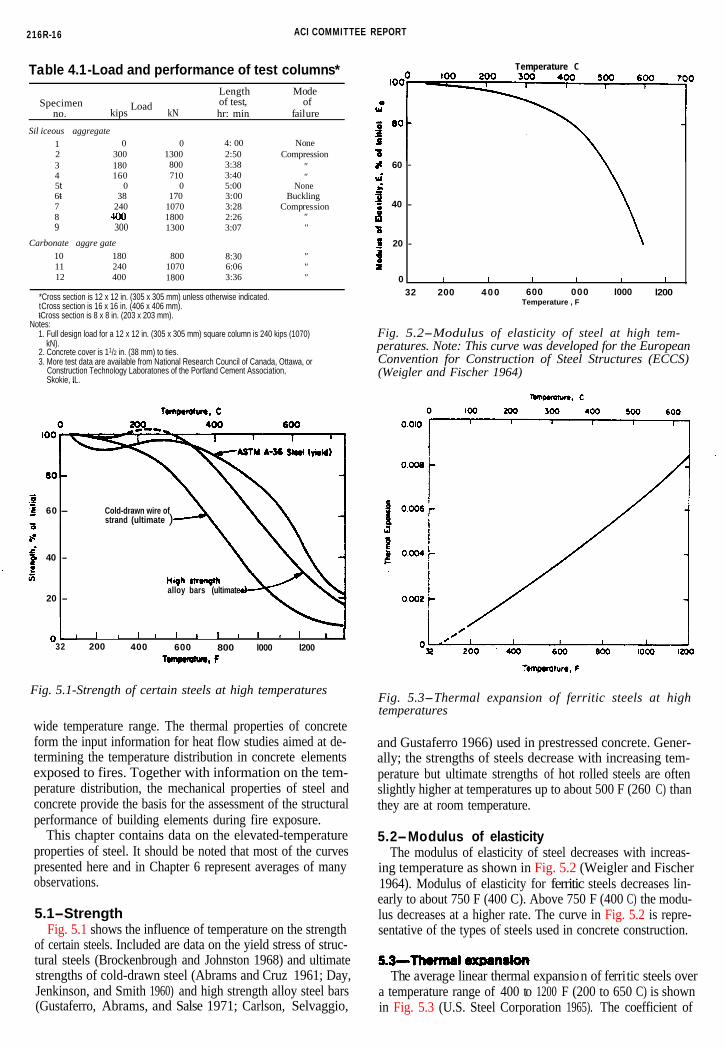
Table 4.1-Load and performance of test columns*Length Mode
Specimenkips
Load kN
of test, ofno. hr: min failure
Sil iceous aggregate1
3 1804 160
7 240
9 300
Carbonate aggre gate10 180 800
12 400
0 02 300 1300
800710
5t 0 06t- 38 170
10708 1800
1300
1800
4: 00 None2:50 Compression3:38 "3:405:003:003:282:263:07 "
"None
BucklingCompression
"
8:30 "11 240 1070 6:06 "
3:36 "
*Cross section is 12 x 12 in. (305 x 305 mm) unless otherwise indicated.tCross section is 16 x 16 in. (406 x 406 mm). t- Cross section is 8 x 8 in. (203 x 203 mm).
Notes:1. Full design load for a 12 x 12 in. (305 x 305 mm) square column is 240 kips (1070)
kN).2. Concrete cover is 11/2 in. (38 mm) to ties.3. More test data are available from National Research Council of Canada, Ottawa, or
Construction Technology Laboratones of the Portland Cement Association, Skokie, IL.
120000
60 - Cold-drawn wire ofstrand (ultimate )
40 -
(ultimate20
alloy bars-
011 ” ’ ” ” ” ” ‘J32 200 400 600 800 l000 l200
Fig. 5.1-Strength of certain steels at high temperatures
wide temperature range. The thermal properties of concreteform the input information for heat flow studies aimed at de-termining the temperature distribution in concrete elementsexposed to fires. Together with information on the tem-perature distribution, the mechanical properties of steel andconcrete provide the basis for the assessment of the structuralperformance of building elements during fire exposure.
This chapter contains data on the elevated-temperatureproperties of steel. It should be noted that most of the curvespresented here and in Chapter 6 represent averages of manyobservations.
5.1-StrengthFig. 5.1 shows the influence of temperature on the strength
of certain steels. Included are data on the yield stress of struc-tural steels (Brockenbrough and Johnston 1968) and ultimatestrengths of cold-drawn steel (Abrams and Cruz 1961; Day,Jenkinson, and Smith 1960) and high strength alloy steel bars(Gustaferro, Abrams, and Salse 1971; Carlson, Selvaggio,
Temperature C
60 -
40 -
20 -
0 I I I I 1 132 32 200 400 600 000 l000 l200
Temperature , F
Fig. 5.2-Modulus of elasticity of steel at high tem-peratures. Note: This curve was developed for the EuropeanConvention for Construction of Steel Structures (ECCS)(Weigler and Fischer 1964)
Fig. 5.3-Thermal expansion of ferritic steels at hightemperatures
and Gustaferro 1966) used in prestressed concrete. Gener-ally; the strengths of steels decrease with increasing tem-perature but ultimate strengths of hot rolled steels are oftenslightly higher at temperatures up to about 500 F (260 C) thanthey are at room temperature.
5.2-Modulus of elasticityThe modulus of elasticity of steel decreases with increas-
ing temperature as shown in Fig. 5.2 (Weigler and Fischer1964). Modulus of elasticity for ferritic steels decreases lin-early to about 750 F (400 C). Above 750 F (400 C) the modu-lus decreases at a higher rate. The curve in Fig. 5.2 is repre-sentative of the types of steels used in concrete construction.
The average linear thermal expansion of ferritic steels overa temperature range of 400 to 1200 F (200 to 650 C) is shownin Fig. 5.3 (U.S. Steel Corporation 1965). The coefficient of
FIRE ENDURANCE OF CONCRETE ELEMENTS 216R-17
loo I = 75F I 24C) 7: 6 9 5 F ( 368 C )2=210F ( 99C) 8= 8 0 0 F 1 4 2 7 C) 7 0 0
3=3OOF (149C) 9 = 900F (482 C )4=4OOF (204C) IO= 9 9 5 F (535 C)5=5OOF (26OC) I I =llOOF (593C) 600
80 6=6OOF (316C) 12=12OOF (649 C)7
100
0200.0 0 0 2 0 . 0 4 0 . 0 6 0 . 0 8 0 . IO 0.1 2
S t r a i n
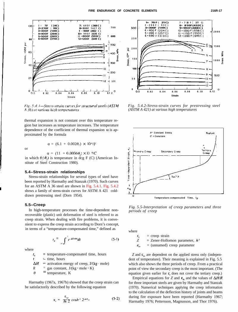
thermal expansion is not constant over this temperature re-gion but increases as temperature increases. The temperaturedependence of the coefficient of thermal expansion GI is ap-proximated by the formula
oro( = (6.1 + 0.0020-1) X IO-VF
o( = (11 + 0.0036H2) X IO ?Cin which 8,( f$) is temperature in dcg F (C) (American In-stitute of Steel Construction 1980).
5.4-Stress-strain relationshipsStress-strain relationships for several types of steel have
been reported by Harmathy and Stanzak (1970). Such curvesfor an ASTM A 36 steel are shown in Fig. 5.4.1. Fig. 5.4.2
2 5 0
‘S 2 0 0
80
-t
1 5 0
t0-I
100
5 0
1= 70 F ( 21 C) 7 = 7 IO F ( 377 C)2 - 2 0 0 F ( 9 3 C ) 8= 810F(432C)3=300F (149C) 9=9lOF(48BC)4=4OOF ( 2 0 4 C ) 10 = 1000F (538C)5=495 F (257C) I I =llOOF(593C)6=590 F (1310C) 12=12OOF(649C) 1 2 0 0 0
45 2 1 5 0 0
0
6_, 0
- 1 0 0 07- k!G
8-
00.0 0 . 0 2 0 . 0 4 0 . 0 6 0 . 0 8 0 . I O 0 . 1 2 -
Strain
Fig. 5.4.2-Stress-strain curves for prestressing steel(ASTM A 421) at various high temperatures
shows a family of stress-strain curves for ASTM A 42 1 cold-drawn prestressing steel (Dorn 1954).
5.5-CreepIn high-temperature processes the time-dependent non-
recoverable (plastic) unit deformation of steel is referred to ascreep strain. When dealing with fire problems, it is conve-nient to express the creep strain according to Dorn’s concept,in terms of a “temperature-compensated time,” defined as
wheret, =tAH 1R =0- =
t, = ‘e-JH’R”dr0 s
temperature-compensated time, hourstime, hoursactivation energy of creep, J/(kg - mole)gas constant, J/(kg * mole - K)temperature, K
Harrnathy (1967a, 1967b) showed that the creep strain canbe satisfactorily described by the following equation
I At Constant Stress
T e m p e r a t u r e - c o m p e n s a t e d T i m e , tg
Fig. 5.5-Interpretation of creep parameters and threeperiods of creep
where
4 = creep strainZ = Zener-Hollomon parameter, h.l&IO = (unnamed) creep parameter
Z and E,~ are dependent on the applied stress only (indepen-dent of temperature). Their meaning is explained in Fig. 5.5which also shows the three periods of creep. From a practicalpoint of view the secondary creep is the most important. (Theequation given earlier for E, does not cover the tertiary creep.)
Empirical equations for Z and E,, and the values of AHIRfor three important steels are given by Harmathy and Stanzak(1970). Numerical techniques applying the creep informationto the calculation of the deflection history of joints and beamsduring fire exposure have been reported (Harmathy 1967;Harmathy 1976; Pettersson, Magnusson, and Thor 1976).
216R-18 ACI COMMITTEE REPORT
I
Temperature, C0100 ,-
F; BO-
%I)
2 60 -Unstressed Residual
mcE* 40-: Avq Initial th = 3900 psi (27MPa)‘vly1?: 20 -S Siliceous Aggregate Concrete \
O- I I 1 /__LI0 4 0 0 8OO 1200 It
Temperature, Fsac
Fig. 6.1.1-Compressive strength of siliceous aggregateconcrete at high temperature and after cooling
Temperature C
5f 60-
Unstressed Residual
5* 4 0 -.?1: Avg Initial 1; : 3900 psi (27 MPa)
E zo-8 Carbonate Aggregate Concrete
800Temperature. F
1200 1600
Fig. 6.1.2-Compressive strength of carbonate aggregateconcrete at high temperature and after cooling
CHAPTER 6-PROPERTIES OF CONCRETE ATHIGH TEMPERATURES
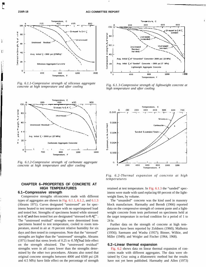
6.1-Compressive strengthCompressive strengths ofconcretes made with different
types of aggregates are shown in Fig. 6.1.1, 6.1.2, and 6.1.3
Temperature, C
2 0 0 4 0 0 6 0 0 8 0 0
Aug. Initial fc of “Unsanded” Concrete= 2600 psi (18 MPa)
k 20Es l
‘,
Avg. Initial 1; of “Sanded” Concrete = 3900 psi 27 MPa)\
Lightweight Aggregate Concrete
01 I I I I I I I J0 4 0 0 800 1200 I 600
Temperature. F
Fig. 6.1 .3-Compressive strength of lightweight concrete athigh temperature and after cooling
(Abrams 1971). Curves designated “unstressed” are for spec-imens heated to test temperature with no superimposed loadand tested hot. Strengths of specimens heated while stressedto O.+f;iand then tested hot are designated “stressed to 0.4f’“.The “unstressed residual” strengths were determined fromspecimens heated to test temperature, cooled to room tem-perature, stored in air at 75 percent relative humidity for sixdays and then tested in compression. Note that the “stressed”strengths are higher than the “unstressed” strengths. Abrams(1971) found that stress levels of 0.25 to 0.55j’had little effecton the strength obtained. The “unstressed residual”strengths were in all cases lower than the strengths deter-mined by the other two procedures. Abrams also noted thatoriginal concrete strengths between 4000 and 6500 psi (28and 4.5 MPa) have little effect on the percentage of strength
Temperature, C
2 0 0 3 0 0 4 0 0 500 6 0 0 7 0 0
0.0 L0 2 0 0 4 0 0 6 0 0 8 0 0 1000 1200
Temperature. F
Fig. 6.2-Thermal expansion of concrete at hightemperatures
retained at test temperature. In Fig. 6.1.3 the “sanded” spec-imens were made with sand replacing 60 percent of the light-weight fines, by volume.
The “unsanded” concrete was the kind used in masonryblock manufacture. Harmathy and Berndt (1966) reporteddata on the compressive strength of cement paste and a light-weight concrete from tests performed on specimens held atthe target temperature in no-load condition for a period of 1 to24 hr.
Further data on the strength of concrete at high tem-peratures have been reported by Zoldners (1960); Malhotra(1956); Saemann and Washa (1957); Binner, Wilkie, andMiller (1949); and Weigler and Fischer (1964, 1968).
6.2-Linear thermal expansionFig. 6.2 shows data on linear thermal expansion of con-
cretes made with different aggregates. The data were ob-tained by Cruz using a dilatometric method but the resultshave not yet been published. Harmathy and Allen (1973)
FIRE ENDURANCE OF CONCRETE ELEMENTS 216R-19
Temperature, C2 0 0 4 0 0 6 0 0
Carbonatee Aggregate Concrete
ui
F 0:E IJJ 60 -t-9 2WE
z-in%3 40 _ Lightweight Aggregate Concrete; a-”P
Eo= 2.6 x 10⁶ psi( 1 9 x10’ MPa)
2 0 - Siliceous Aggregate Concrete
E,= 5.5 x IO6 psi( 3 6 x.10’ MPa)
0 I I I I I3 2 4 0 0 8 0 0 1200
Temperature. F
Fig. 6.3.1-Modulus of elasticity of concrete at hightemperatures
studied the thermal expansion of 16 different concretes usedin masonry units. Among these, pumice concretes werefound to exhibit considerable shrinkage at temperaturesabove 600 F (3 15 C). Dettling (1964) pointed out that thermalexpansion of concrete is influenced by aggregate type, ce-ment content, water content, and age. Philleo (1958) per-formed tests on a carbonate aggregate concrete using a differ-ent technique. He obtained somewhat higher values thanthose obtained by Cruz at temperatures above 700 F (370 C).
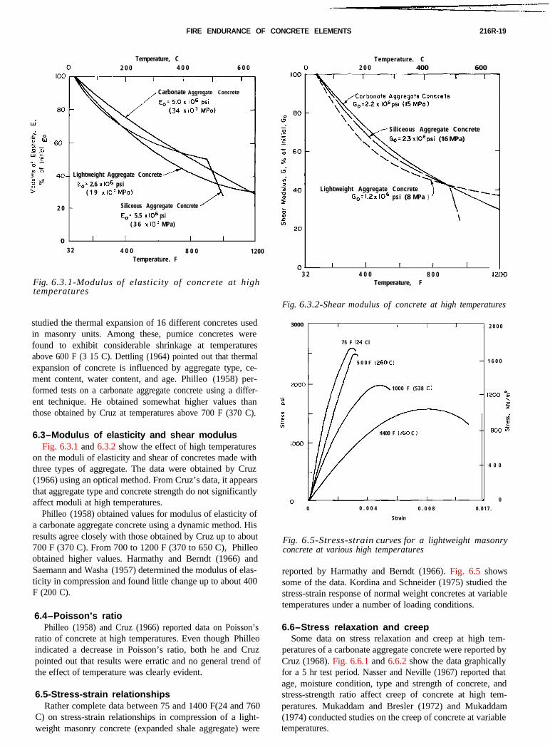
6.3-Modulus of elasticity and shear modulusFig. 6.3.1 and 6.3.2 show the effect of high temperatures
Temperature. C2 0 0 400 600
Siliceous Aggregate Concrete
w’23x106psi (16 MPa)
Lightweight Aggregate ConcreteGo= 1.2 x IO6 psi (8 MPa )
I I I I I3 2 4 0 0 8 0 0 I200
Temperature, F
Fig. 6.3.2-Shear modulus of concrete at high temperatures
on the moduli of elasticity and shear of concretes made withthree types of aggregate. The data were obtained by Cruz(1966) using an optical method. From Cruz’s data, it appearsthat aggregate type and concrete strength do not significantlyaffect moduli at high temperatures.
Philleo (1958) obtained values for modulus of elasticity ofa carbonate aggregate concrete using a dynamic method. Hisresults agree closely with those obtained by Cruz up to about700 F (370 C). From 700 to 1200 F (370 to 650 C), Philleoobtained higher values. Harmathy and Berndt (1966) andSaemann and Washa (1957) determined the modulus of elas-ticity in compression and found little change up to about 400F (200 C).
6.4-Poisson’s ratioPhilleo (1958) and Cruz (1966) reported data on Poisson’s
ratio of concrete at high temperatures. Even though Philleoindicated a decrease in Poisson’s ratio, both he and Cruzpointed out that results were erratic and no general trend ofthe effect of temperature was clearly evident.
6.5-Stress-strain relationshipsRather complete data between 75 and 1400 F(24 and 760
C) on stress-strain relationships in compression of a light-weight masonry concrete (expanded shale aggregate) were
3000 I I 1 I I . 2 0 0 0
75 F 124 Cl
5 0 0 F (260C) - 1 6 0 0
1000 F (538 C)- 1200 “E.-
: 1-L
2E
i*
1400 F (760 C I - l3ooG
- 4 0 0
* 0
0 0 . 0 0 4 0 . 0 0 8 0 . 0 1 7 .
Strain
Fig. 6.5-Stress-strain curves for a lightweight masonryconcrete at various high temperatures
reported by Harmathy and Berndt (1966). Fig. 6.5 showssome of the data. Kordina and Schneider (1975) studied thestress-strain response of normal weight concretes at variabletemperatures under a number of loading conditions.
6.6-Stress relaxation and creepSome data on stress relaxation and creep at high tem-
peratures of a carbonate aggregate concrete were reported byCruz (1968). Fig. 6.6.1 and 6.6.2 show the data graphically
for a 5 hr test period. Nasser and Neville (1967) reported thatage, moisture condition, type and strength of concrete, andstress-strength ratio affect creep of concrete at high tem-peratures. Mukaddam and Bresler (1972) and Mukaddam(1974) conducted studies on the creep of concrete at variabletemperatures.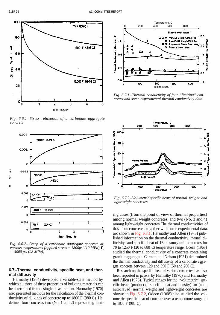
216R-20 ACI COMMITTEE REPORT
80
‘i._‘g 6 0‘0at
$ 4 0Lz
I \ 600 F (316C) l
Cl20 l 1
.o-0 1 2 3 4 5
Test Time, hr
Fig. 6.6.1-Stress relaxation of a carbonate aggregateconcrete
0.004
s 0 0 0 2
5
8 0
0.001
0
0001 I
300F lr4QC)I I
0 L I I i
0.001
0
(24 ClI I I
I0 I 2 3 4 5
lbst Tii hr
Fig. 6.6.2-Creep of a carbonate aggregate concrete atvarious temperatures [applied stress = 1800psi (12 MPa), f:= 4000 psi (28 MPa)]
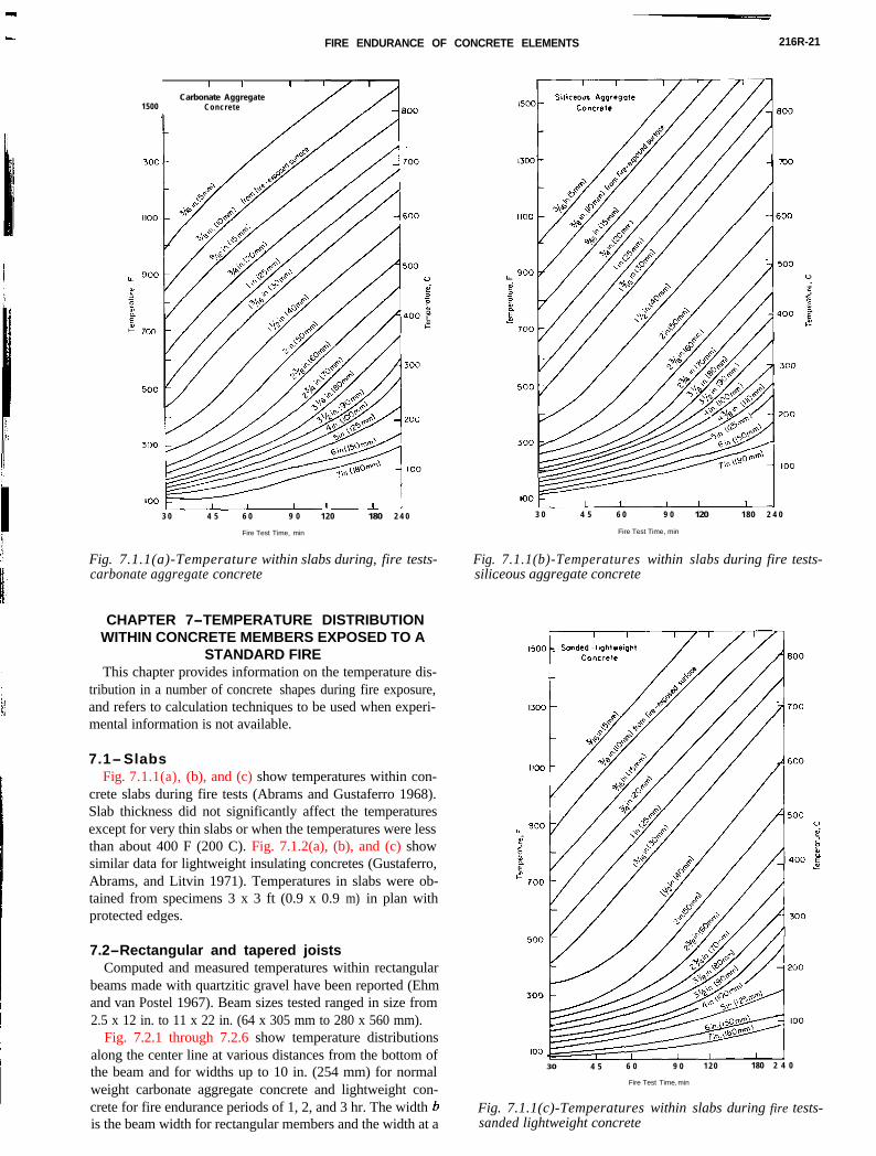
6.7-Thermal conductivity, specific heat, and ther-mal diffusivity
Harmathy (1964) developed a variable-state method bywhich all three of these properties of building materials canbe determined from a single measuremcnt. Harmathy (1970)also presented methods for the calculation of the thermal con-ductivity of all kinds of concrete up to 1800 F (980 C). Hedefined four concretes two (No. 1 and 2) representing limit-
Temperature, c0 200 400
1.6I.6600 800
n I 1
0.0 1 I I I I
0 400 600 I200 1600Temperature, F
Fig. 6.7.1-Thermal conductivity of four “limiting” con-cretes and some experimental thermal conductivity data
Fig. 6.7.2-Volumetric specific heats of normal weight andlightweight concretes
ing cases (from the point of view of thermal properties)among normal weight concretes, and two (No. 3 and 4)among lightweight concretes. The thermal conductivities ofthese four concretes. together with some experimental data.arc shown in Fig. 6.7.1. Harmathy and Allen (1973) pub-lished information on the thermal conductivity, thermal di-ffusivity. and specific heat of 16 masonry unit concretes for70 to 1250 F (20 to 680 C) temperature range. Odeen (1968)studied the thermal conductivity of a concrete containinggranitic aggregate. Carman and Nelson (1921) determinedthe thermal conductivity and diffusivity of a carbonate aggre-gate concrete between 120 and 390 F (50 and 200 C).
Research on the specific heat of various concretes has alsobeen reported in papers by Harmathy (1970) and Harmathyand Allen (1973). Typical ranges for the “volumetric” spe-cific heats (product of specific heat and density) for (non-autoclaved) normal weight and lightweight concretes areshown in Fig. 6.7.2, Odeen (1968) also studied the vol-umetric specific heat of concrete over a temperature range upto 1800 F (980 C).
FIRE ENDURANCE OF CONCRETE ELEMENTS 216R-21
CHAPTER 7-TEMPERATURE DISTRIBUTIONWITHIN CONCRETE MEMBERS EXPOSED TO A
STANDARD FIREThis chapter provides information on the temperature dis-
tribution in a number of concrete shapes during fire exposure,and refers to calculation techniques to be used when experi-mental information is not available.
I I t
Carbonate Aggregate1500 Concrete
3 0 4 5 6 0 9 0 120 180 2 4 0
Fire Test Time, min
Fig. 7.1.1(a)-Temperature within slabs during, fire tests-carbonate aggregate concrete
7.1-SlabsFig. 7.1.1(a), (b), and (c) show temperatures within con-
Fig. 7.1.1(b)-Temperatures within slabs during fire tests-silic.eous aggregate concrete
3 0 4 5 6 0 9 0 120 180 2 4 0
Fire Test Time, min
c ’ ’1500 _ Sanded-llqhtweiqht
30 4 5 6 0 9 0 1 2 0 180 2 4 0
Fire Test Time, min
Fig. 7.1.1(c)-Temperatures within slabs during fire tests-sanded lightweight concrete
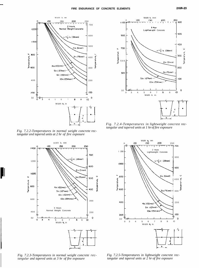
crete slabs during fire tests (Abrams and Gustaferro 1968).Slab thickness did not significantly affect the temperaturesexcept for very thin slabs or when the temperatures were lessthan about 400 F (200 C). Fig. 7.1.2(a), (b), and (c) showsimilar data for lightweight insulating concretes (Gustaferro,Abrams, and Litvin 1971). Temperatures in slabs were ob-tained from specimens 3 x 3 ft (0.9 x 0.9 m) in plan withprotected edges.
7.2-Rectangular and tapered joistsComputed and measured temperatures within rectangular
beams made with quartzitic gravel have been reported (Ehmand van Postel 1967). Beam sizes tested ranged in size from2.5 x 12 in. to 11 x 22 in. (64 x 305 mm to 280 x 560 mm).
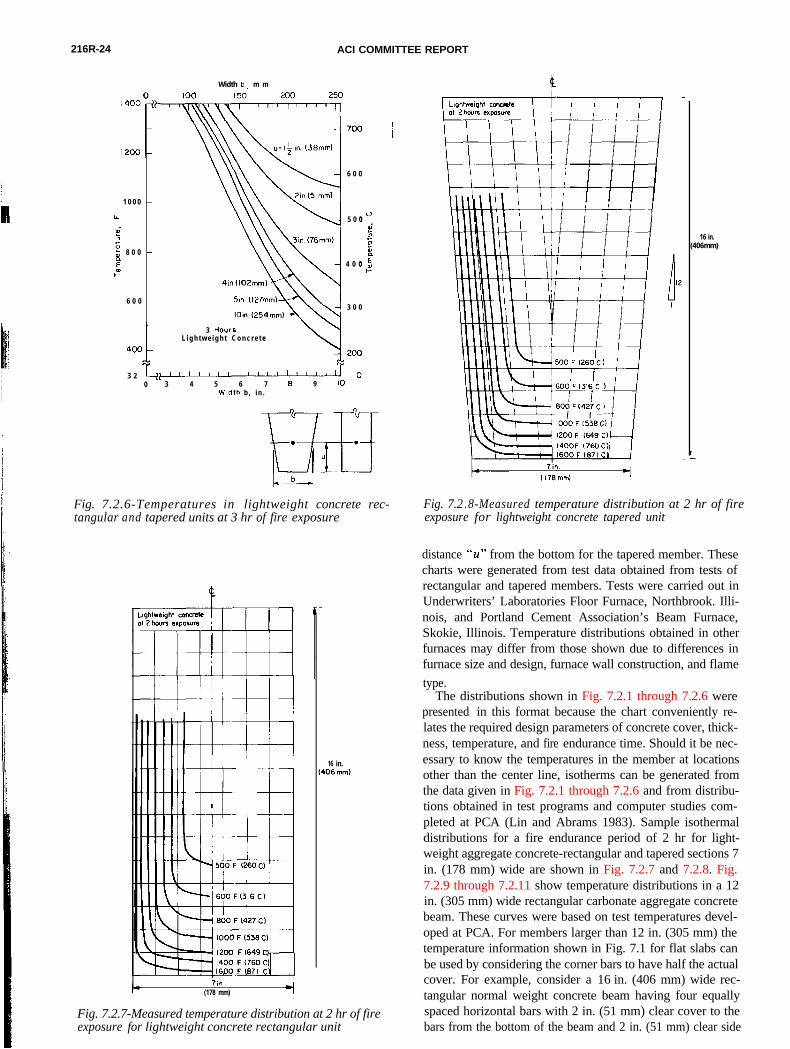
Fig. 7.2.1 through 7.2.6 show temperature distributions
along the center line at various distances from the bottom ofthe beam and for widths up to 10 in. (254 mm) for normalweight carbonate aggregate concrete and lightweight con-crete for fire endurance periods of 1, 2, and 3 hr. The width bis the beam width for rectangular members and the width at a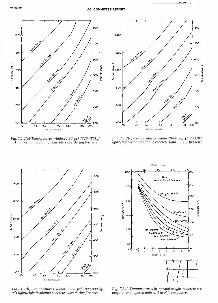
216R-22 ACI COMMITTEE REPORT
LL
P
$ 1000
%Ec”
600
30 4 5 6 0 9 0 120 160 2 4 0
Fire Test Time, min Fire Test Time, min
Fig. 7.1.2(a)-Temperatures within 20-30 pcf (320-480 kg/ Fig. 7.1.2(c)-Temperatures within 70-80 pcf (1120-1280m’) lightweight insulating concrete slabs during fire tests kg/w-‘) lightweight insulating concrete slabs during fire tests
Width 4 mm
Fire Test Time, min
Fig 7.1.2(b)-Temperatures within 50-60 pcf (800-900 kg/lightweight insulating concrete slabs during fire tests
Fig. 7.2 .1-Temperatures in normal weight concrete rec-tn-‘) tangular and tapered units at 1 hr of fire exposure
I too
900
7 0 0IL
E20x6 5 0 0
r-”
3 0 0
100
3 :
0
Iloin 1254mm)’
3 4 5 6 7 Et 9 IO
Width b, in.
FIRE ENDURANCE OF CONCRETE ELEMENTS 216R-23
W i d t h b , mm Width b, mm0 1002-6wloo 150 200 250
7 0 0
6 0 0
5 0 0
u
4 0 0 $
zx
3 0 0 E
2 0 0
1100
900
LL 700
5D“pE 5 0 0I-”
300
:
I 200
1000
4 0 0
32
Lightweight Concrete
ttc
3 2 I I I I IO
0 3 4 5 6 7 6 9 IOWidth b. in.
“3 4 5 6 7 1 I8 9 10’
Width b, in
Fig. 7.2.4-Temperatures in lightweight concrete rec-tangular and tapered units at 1 hr of fire exposure
Fig. 7.2.2-Temperatures in normal weight concrete rec-tangular and tapered units at 2 hr of fire exposure
w i d t h b, mm 0Width 4 mm
100 150 200 2 5 0
1400
I 2002 Hours
Lightweight Concrete
- 6 0 0
1200
1000”
4 0 0 $2exE
3 0 0 I-”
3 Hours
4 0 0Normal Weight Concrete l
+
3 0 0
2 0 0
2 0 0
3 2 +-?,I------+I
6 0 0
3 2 $-- J-----JO5 6 7 8 9 IO
0 3 4 5 6 7 8 9 IO
Width b, in.Width b, in
Fig. 7.2.3-Temperatures in normal weight concrete rec- Fig. 7.2.5-Temperatures in lightweight concrete rec-tangular and tapered units at 3 hr of fire exposure tangular and tapered units at 2 hr of fire exposure
216R-24 ACI COMMITTEE REPORT
Width b. m m
6 0 0
1 0 0 0 -
LL 5 0 0
d;‘;; 8 0 0 -
: 4 0 0I-”
6 0 0 -3 0 0
3 HoursL i g h t w e i g h t C o n c r e t e
3 20 3 4 5 6 7 6 9 IO
Width b , in .
m. .I I ”
b-4Fig. 7.2.6-Temperatures in lightweight concrete rec- tangular and tapered units at 3 hr of fire exposure
I(260
1200 Fl649C
16 in.
7in(178 mm)
Fig. 7.2.7-Measured temperature distribution at 2 hr of fireexposure for lightweight concrete rectangular unit
Fig. 7.2 .8-Measured temperature distribution at 2 hr of fireexposure for lightweight concrete tapered unit
16 in.(406mm)
distance "u" from the bottom for the tapered member. Thesecharts were generated from test data obtained from tests ofrectangular and tapered members. Tests were carried out inUnderwriters’ Laboratories Floor Furnace, Northbrook. Illi-nois, and Portland Cement Association’s Beam Furnace,Skokie, Illinois. Temperature distributions obtained in otherfurnaces may differ from those shown due to differences infurnace size and design, furnace wall construction, and flame
type.The distributions shown in Fig. 7.2.1 through 7.2.6 were
presented in this format because the chart conveniently re-lates the required design parameters of concrete cover, thick-ness, temperature, and fire endurance time. Should it be nec-essary to know the temperatures in the member at locationsother than the center line, isotherms can be generated fromthe data given in Fig. 7.2.1 through 7.2.6 and from distribu-tions obtained in test programs and computer studies com-pleted at PCA (Lin and Abrams 1983). Sample isothermaldistributions for a fire endurance period of 2 hr for light-weight aggregate concrete-rectangular and tapered sections 7in. (178 mm) wide are shown in Fig. 7.2.7 and 7.2.8. Fig.7.2.9 through 7.2.11 show temperature distributions in a 12
in. (305 mm) wide rectangular carbonate aggregate concretebeam. These curves were based on test temperatures devel-oped at PCA. For members larger than 12 in. (305 mm) thetemperature information shown in Fig. 7.1 for flat slabs canbe used by considering the corner bars to have half the actualcover. For example, consider a 16 in. (406 mm) wide rec-tangular normal weight concrete beam having four equallyspaced horizontal bars with 2 in. (51 mm) clear cover to thebars from the bottom of the beam and 2 in. (51 mm) clear side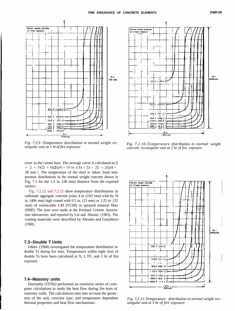
FIRE ENDURANCE OF CONCRETE ELEMENTS 216R-25
16,~IO6 mm)
I- 12 in.( 305 mm)
Fig. 7.2.9 -Temperature distribution in normal weight rec-tangular unit at 1 hr of fire exposure
IJOOF 1704C)1500 F 1616 C )17OOF ,527 C)
I-- 12 r.1305mml
Fig. 7.2.10-Temperature distribution in normal weightconcrete rectangular unit at 2 hr of fire exposure
i i i,I
,/I I I .,I I
500 F (260 C) /i ii i i 11
- 17OOF 1 9 2 7 C l ’ ’ ’ I
16 in.
106md
IFig. 7.2.11-Temperature distribution in normal weight rec-tangular unit at 3 hr of fire exposure
cover to the corner bars. The average cover is calculated as [2+ 2 + S(2) + %(2)]/4 = 1Min. [(Sl - 51 - 25 - 25)/4 =38 mm ] . The temperature of the steel is taken from tem-perature distributions in the normal weight concrete shown inFig. 7.1 for the 1.5 in. (38 mm) distance from the exposedsurface.
Fig. 7.2.12 and 7.2.13 show temperature distributions in
carbonate aggregate concrete joists 4 in. (102 mm) wide by 16in. (406 mm) high coated with 0.5 in. (13 mm) or 1.25 in. (32mm) of vermiculite CM (VCM) or sprayed mineral fiber(SMF). The tests were made at the Portland Cement Associa-tion laboratories and reported by Lin and Abrams (1983). Thecoating materials were described by Abrams and Gustaferro(1968).7.3-Double T UnitsOdeen (1968) investigated the temperature distribution in
double Ts during fire tests. Temperatures within eight sizes ofdouble Ts have been calculated at %, 1, l%, and 2 hr of fireexposure.
7.4-Masonry unitsHarmathy (1970a) performed an extensive series of com-
puter calculations to study the heat flow during fire tests ofmasonry walls. The calculations take into account the geom-etry of the unit, concrete type, and temperature dependentthermal properties and heat flow mechanisms.
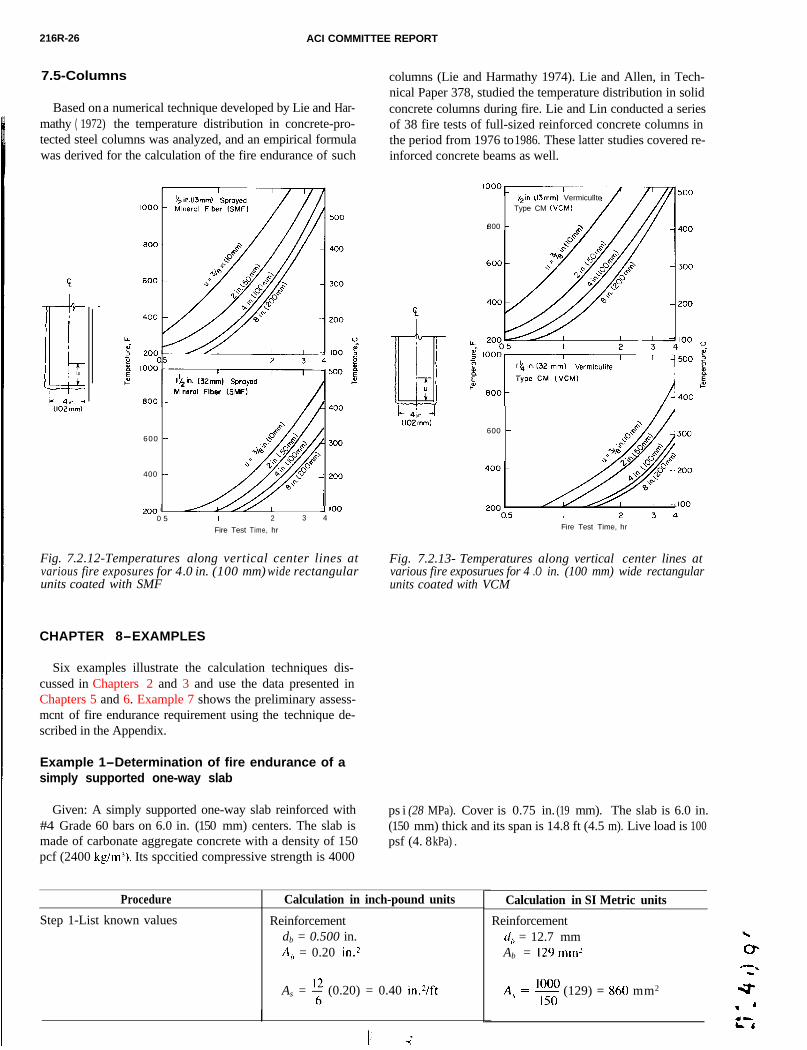
216R-26 ACI COMMITTEE REPORT
Example 1-Determination of fire endurance of asimply supported one-way slab
Given: A simply supported one-way slab reinforced with#44 Grade 60 bars on 6.0 in. (15050 mm) centers. The slab ismade of carbonate aggregate concrete with a density of 1500pcf (2400 kgimj). Its spccitied compressive strength is 4000
ps i (28 MPa). Cover is 0.75 in. (19 mm). The slab is 6.0 in.(15050 mm) thick and its span is 14.8 ft (4.5 m). Live load is 100psf (4. 8 kPa) .)
Procedure
Step 1-List known values
Calculation in inch-pound units Calculation in SI Metric units
Reinforcement Reinforcementdb = 0.500 in. d,, = 12.7 mmA,) = 0.20 in.2 Ab = 129 mm?
As = f (0.20) = 0.40 in.Vft A, =!?$ (129) = 860 mm2
600 -
400 -
I 71000 5 I 2 3 4
Fire Test Time, hr
Fig. 7.2 .12-Temperatures along vertical center lines atvarious fire exposures for 4 .0 in. (100 mm) wide rectangularunits coated with SMF
600 -
Fire Test Time, hr
Fig. 7.2.13- Temperatures along vertical center lines atvarious fire exposurues for 4 .O in. (100 mm) wide rectangularunits coated with VCM
VermiculiteType CM (KM)
800 -
7.5-Columns
Based on a numerical technique developed by Lie and Har-mathy ( 1972) the temperature distribution in concrete-pro-tected steel columns was analyzed, and an empirical formulawas derived for the calculation of the fire endurance of such
CHAPTER 8-EXAMPLES
Six examples illustrate the calculation techniques dis-cussed in Chapters 2 and 3 and use the data presented inChapters 5 and 6. Example 7 shows the preliminary assess-
mcnt of fire endurance requirement using the technique de-scribed in the Appendix.columns (Lie and Harmathy 1974). Lie and Allen, in Tech-nical Paper 378, studied the temperature distribution in solidconcrete columns during fire. Lie and Lin conducted a seriesof 38 fire tests of full-sized reinforced concrete columns inthe period from 1976 to 1986. These latter studies covered re-inforced concrete beams as well.
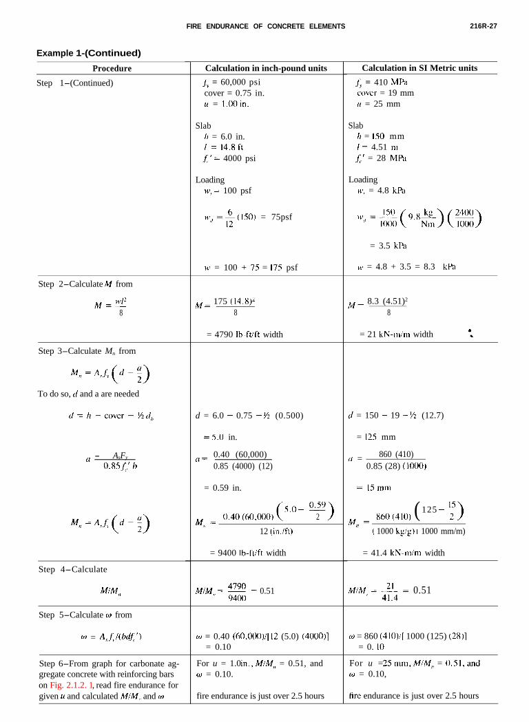
FIRE ENDURANCE OF CONCRETE ELEMENTS 216R-27
Example 1-(Continued)
Procedure
Step 1-(Continued)
Step 2-Calculate M from
M=“‘I?8
Step 3-Calculate Mn from
M,, = A,j;.
To do so, d and a are needed
AsFy‘, -0.85X' b
M,, = A,f,
Step 4-Calculate
Step 5-Calculate w from
w = A,,~,l(bdj;‘)
Step 6-From graph for carbonate ag-gregate concrete with reinforcing barson Fig. 2.1.2. 1, read fire endurance forgiven u and calculated M/M,, and w
Calculation in inch-pound units
J_i, = 60,000 psicover = 0.75 in.u = 1.00 in.
Slabk = 6.0 in.1 = 14.8ftf’ ’ = 4000 psi<
LoadingW’, = 100 psf
b$“/ = *(ISo) = 75psf
\I’ = 100 + 75 = 175 psf
M = 175 (14.8)j8
M = 8.3 (4.51)2
8
= 4790 lb-ft/ft width = 21 kN-m/m width
d = 6.0 - 0.75 - fi (0.500)
= 5.0 in.
a = 0.40 (60,000)0.85 (4000) (12)
= 0.59 in.
5.0 - 0.59M = 0.40(60,000) 2 >
,?12 (in.fft)
= 9400 lb-ft/ft width
M/M,, = z = 0.51
w = 0.40 (6O,OOOj/[ 12 (5.0) (4000)]= 0.10
For u = 1.0 in.,M/M,, = 0.51, andW = 0.10.
fire endurance is just over 2.5 hours
Calculation in SI Metric units
j.;, = 410 MPa
cover = 19 mm1( = 25 mm
Slab/z = 150 mmI = 4.51 111
f;.’ = 28 MPa
Loadingu’, = 4.8 kPa
‘l’d =~(9.8~)(=!)
= 3.5 kF’a
H’ = 4.8 + 3.5 = 8.3 kPa
d = 150 - 19 - M (12.7)
= 125 mm
(1 = 860 (410)0.85 (28) (1000)
= 15 mm
M = 860(410) ( 125 -:I>
I,( 1000 kg/g) ( 1000 mm/m)
= 41.4 kN-m/m width
M/M,, = c4 = 0.51
w = 860 (410)/[ 1000 (125) (28)l= 0. IO
For u = 25mm,M/M,, = O.Sl,and0 = 0.10,
fire endurance is just over 2.5 hours
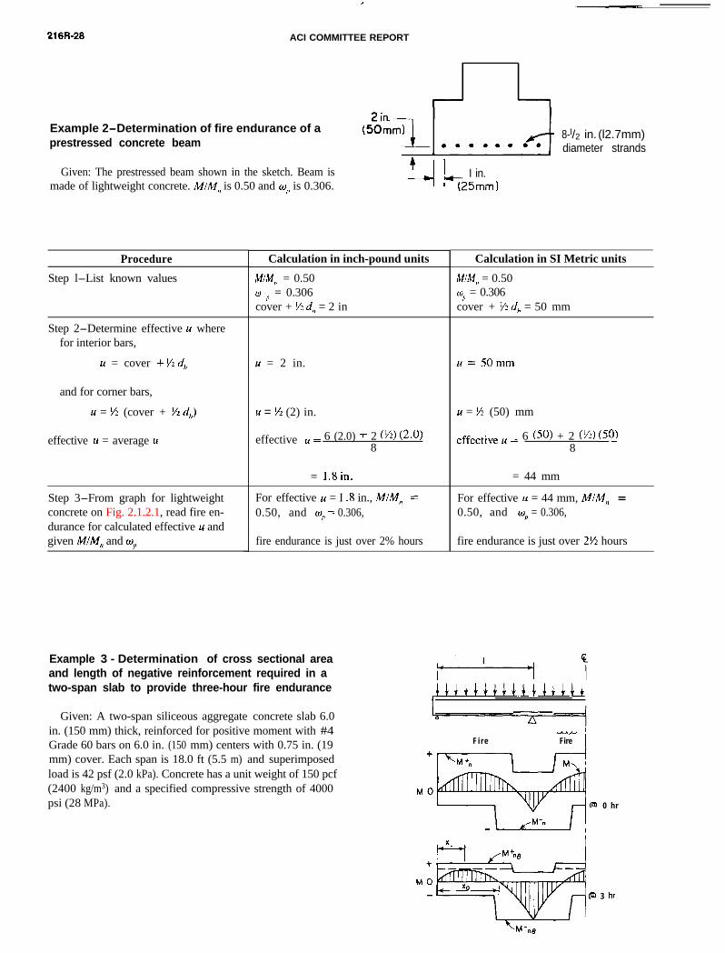
216R-28 ACI COMMITTEE REPORT
Example 2-Determination of fire endurance of aprestressed concrete beam
Given: The prestressed beam shown in the sketch. Beam ismade of lightweight concrete. A~/IW,~ is 0.50 and w,, is 0.306.
Procedure
Step l-List known values
Step 2-Determine effective u wherefor interior bars,
u = cover + Vz d,,
and for corner bars,
u = % (cover + % d,)
effective K = average u
Step 3-From graph for lightweightconcrete on Fig. 2.1.2.1, read fire en-durance for calculated effective u andgiven MIM,, and w,,
9-- I in.(25mm 1
Calculation in inch-pound units
MIM,, = 0.50
@ I' = 0.306cover + % d,, = 2 in
24 = 2 in.
u = % (2) in.
effective u = 6 (2.0) + 2 (~) (2.0)8
= l.Bin.
For effective u = I .8 in., M/M, =0.50, and o, = 0.306,
fire endurance is just over 2% hours
8-l/2 in. (l2.7mm)diameter strands
Calculation in SI Metric units
M/M,, = 0.50wrj = 0.306cover + M d, = 50 mm
r4=50mm
r4 = M (50) mm
effective u = 6 (50) + 2 (‘) (53_)8
= 44 mm
For effective u = 44 mm, M/M,, =0.50, and o, = 0.306,
fire endurance is just over 2% hours
Example 3 - Determination of cross sectional areaand length of negative reinforcement required in atwo-span slab to provide three-hour fire endurance
Given: A two-span siliceous aggregate concrete slab 6.0in. (150 mm) thick, reinforced for positive moment with #4Grade 60 bars on 6.0 in. (150 mm) centers with 0.75 in. (19mm) cover. Each span is 18.0 ft (5.5 m) and superimposedload is 42 psf (2.0 kPa). Concrete has a unit weight of 150 pcf(2400 kg/m3) and a specified compressive strength of 4000psi (28 MPa).
I+++++++u++~+~++
Fi re-’Fire 1
+
@I 0 hr
3 hr
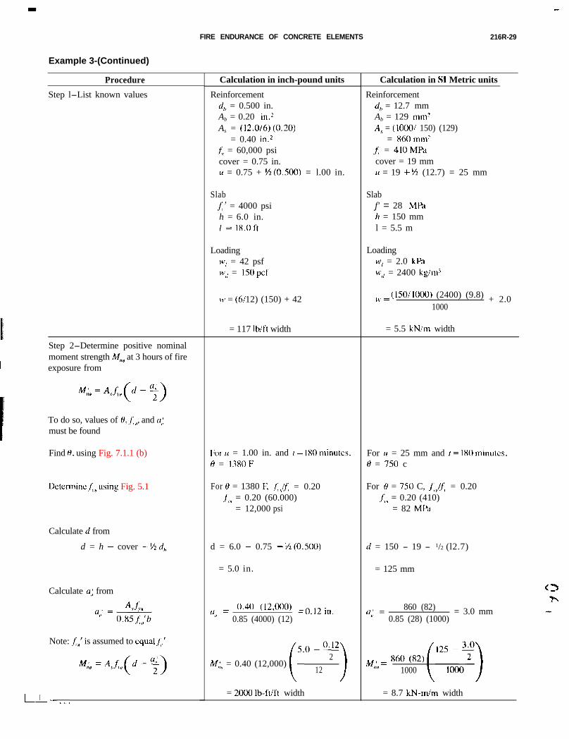
FIRE ENDURANCE OF CONCRETE ELEMENTS 216R-29
Example 3-(Continued)
Procedure
Step l-List known values
Step 2-Determine positive nominalmoment strength IV;@ at 3 hours of fireexposure from
MA = ‘vi” Cd-%)To do so, values of H,~f,“, and N,;must be found
Find 0, using Fig. 7.1.1 (b)
DetermineJ,,using Fig. 5.1
Calculate d from
d = h - cover - M d,
Calculate al; from
0’ = A,.&”” 0.85j”‘h
Note: ,&’ is assumed to cqualfj.’
I,..
Calculation in inch-pound units
Reinforcementcl, = 0.500 in.Ab = 0.20 in.*As = (12.0/6)(0.20)
= 0.40 in.2,f, = 60,000 psicover = 0.75 in.II = 0.75 + E(O.500) = l.00 in.
SlabA_’ = 4000 psih = 6.0 in.I = 18.0 ft
LoadingW, = 42 psf
).$“I = 150 pcf
\o = (6/12) (150) + 42
= 117 lb/R width
Forlr = 1.00 in. and I = 180 minutes,0 = 1380F
For 0 = 1380 F, .f;,,!f, = 0.20,f,, = 0.20 (60.000)
= 12,000 psi
d = 6.0 - 0.75 - ti(O.500)
= 5.0 in.
(1,; = o’40 (12,000) = 0.12 in.
0.85 (4000) (12)
50-0.122
M,;” = 0.40 (12,000) (. >12
= 2000 lb-ft/ft width
Calculation in SI Metric units
Reinforcementd,, = 12.7 mmAb = 129 mm?A,” = (1000 / 150) (129)
= 860mm?j;, = 410 MPacover = 19 mmu = 19 + ‘/z (12.7) = 25 mm
Slabf' = 28 MPa. ch = 150 mml = 5.5 m
LoadingW, = 2.0 kPa
‘(‘<l = 2400 kg/m’
),, = (150/1000) (2400) (9.8) + 2.01000
= 5.5 kN/m width
For II = 25 mm and 1 = 1X0 minutes,H = 750 c
For H = 750 C, f,,lf,. = 0.20.I,,, = 0.20 (410)
= 82 MPd
cl = 150 - 19 - 1/2 (l2.7)
= 125 mm
0,; =860 (82) = 3.0 mm
0.85 (28) (1000)
/,,,< = 860 (82)“0 1000
= 8.7 kN-m/m width
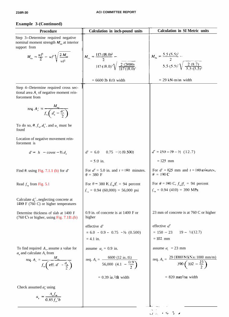
216R-30 ACI COMMITTEE REPORT
Example 3-(Continued)
Procedure
Step 3-Determine required negativenominal moment strength M,;, at interiorsupport from
Step 4-Determine required cross sec-tional area A; of negative moment rein-forcement from
To do so, 0, j;,,, do’, and N(, must befound
Location of negative movement rein-forcement is
d' = h - cover - S/2,,
Find 0, using Fig. 7.1.1 (b) for d'
Read j;,, from Fig. 5.1
Calculate d,,‘, neglecting concrete at1400 F (760 C) or higher temperatures
Determine thickness of slab at 1400 F(760 or higher, using Fig. 7.1.1.(b)
To find required A<, assume a value forCI~ and calculate As from
req.A, =
Check assumed a; using
Calculation in inch-pound units
= 6600 lb-ft/ft width
d' = 6.0 - 0.75 - ~(0.500)
= 5.0 in.
For rl’ = 5.0 in. and 1 = 180 minutes.0 = 380 F
For 0 = 380 F. j;.,!t = 94 percent
.f,,, = 0.94 (60,000) = 56,000 psi
0.9 in. of concrete is at 1400 F orhigher
effective d'
= 6.0 - 0.9 - 0.75 - ti (0.500)
= 4.1 in.
assume LI, = 0.9 in.
req. As =6600 (12 in./ft)
56,000 (4.1 - y)
= 0.39 in.2/ft width
i
i
,
Calculation in SI Metric units
= 29 kN-m/m width
!I’ = IS0 - I9 - S (12.7)
= 12.5 mm
For d' = 125 mm and 1 = 180 minutes,6r = 19oc
For H = I90 C, f;.,/j:, = 94 percent
f,.,, = 0.94 (410) = 390 MPa
23 mm of concrete is at 760 C or higher
effective cl’
= 150 - 23 - 19 - 1/2(12.7)
= 102 mm
assume 0 I< = 23 mm
req. As =29 (IO00 NIkN) ( 1000 mm/m)
390(102 -y)
= 820 mm?m width
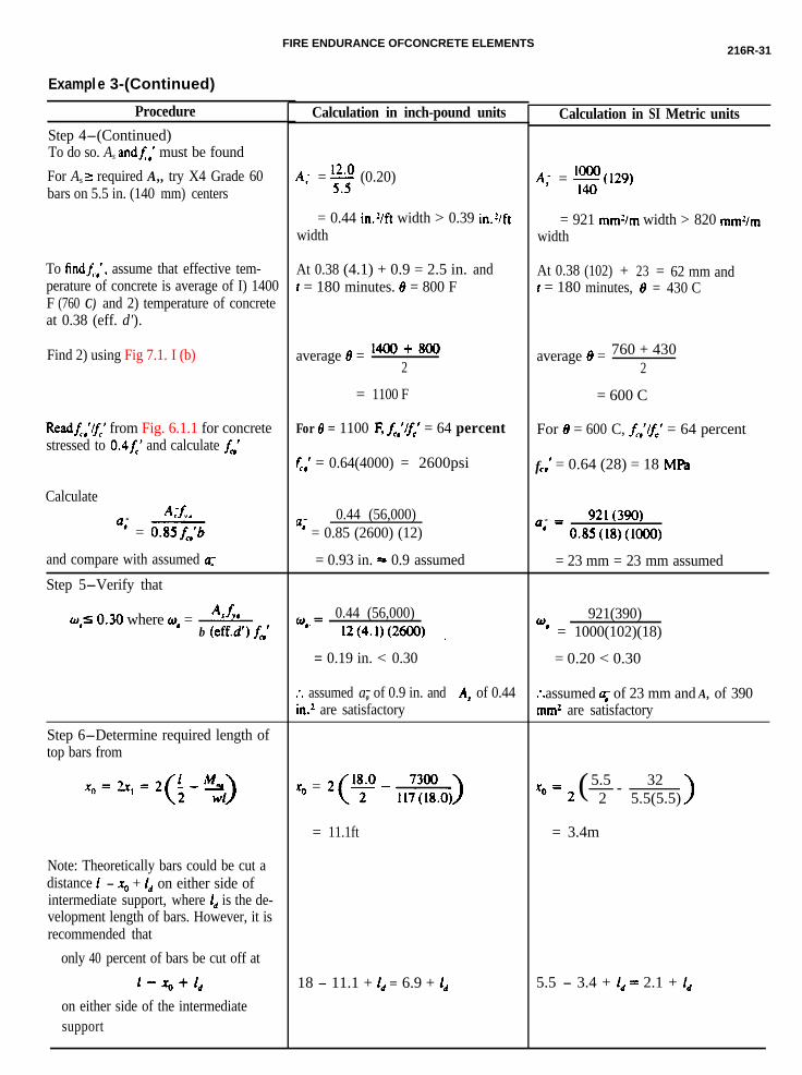
FIRE ENDURANCE OFCONCRETE ELEMENTS216R-31
Exampl e 3-(Continued)
Procedure
Step 4-(Continued)To do so. As andA,’ must be found
For As 2 required A,, try X4 Grade 60bars on 5.5 in. (140 mm) centers
To findi.,‘. assume that effective tem-perature of concrete is average of I) 1400F (760 C) and 2) temperature of concreteat 0.38 (eff. d').
Find 2) using Fig 7.1. I (b)
Readf,,‘/” from Fig. 6.1.1 for concretestressed to 0.4f,’ and calculate f,’
Calculate
“- = 0.85f,‘b
and compare with assumed a:
Step 5-Verify that
qlO.30 where W, = A*f,, 0.44 (56,000)b (eff.d’) f,’ %= 12(4.1)(2600) .
Step 6-Determine required length oftop bars from
Note: Theoretically bars could be cut adistance 1 - x0 + 1, on either side ofintermediate support, where l,, is the de-velopment length of bars. However, it isrecommended that
only 40 percent of bars be cut off at
l-%+1,
on either side of the intermediatesupport
Calculation in inch-pound units
AI- = z (0.20)
= 0.44 in.?ft width > 0.39 in.?/ftwidth
At 0.38 (4.1) + 0.9 = 2.5 in. andt = 180 minutes. 8 = 800 F
average 8 = lW+8002
= 1100 F
For 8 = 1100 E f,‘lf,’ = 64 percent
fCI ’ = 0.64(4000) = 2600psi
0.44 (56,000)“’ = 0.85 (2600) (12)
= 0.93 in. = 0.9 assumed
= 0.19 in. < 0.30
:. assumed a0- of 0.9 in. and A, - of 0.44in.2 are satisfactory
x0 =
= 11.1ft
18 - 11.1 + 1, = 6.9 + ld
Calculation in SI Metric units
4 = E(l29,
= 921 mm?m width > 820 mmz/mwidth
At 0.38 (102) + 23 = 62 mm andt = 180 minutes, 8 = 430 C
average 8 = 760 + 4302
= 600 C
For 8 = 600 C, f,‘lfc’ = 64 percent
fL-I ’ = 0.64 (28) = 18 MW
921(390)” = 0.85(18)(1000)
= 23 mm = 23 mm assumed
921(390)WI = 1000(102)(18)
= 0.20 < 0.30
* assumed 4 of 23 mm and A, of 390. .mm2 are satisfactory
x0= 2 (5.5 32- - -2 5.5(5.5)
= 3.4m
5.5 - 3.4 + 1, = 2.1 + ld
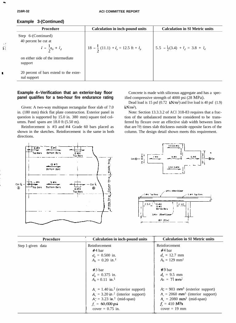
I! I
216R-32 ACI COMMITTEE REPORT
c
Example 3-(Continued)
Procedure
Step 6-(Continued)40 percent be cut at
1 - +(, + I,
on either side of the intermediatesupport
Calculation in inch-pound units Calculation in SI Metric units
18 - ; (11.1) + I, = 12.5 ft + 1, 5.5 - 1-2 (3.4) + I<, = 3.8 + ld
20 percent of bars extend to the exter-nal support
Example 4-Verification that an exterior-bay floorpanel qualifies for a two-hour fire endurance rating
Given: A two-way multispan rectangular floor slab of 7.0in. (180 mm) thick flat plate construction. Exterior panel inquestion is supported by 15.0 in. 380 mm) square tied col- col-umns. Panel spans are 18.0 ft (5.50 m).
Reinforcement is #3 and #4 Grade 60 bars placed asshown in the sketches. Reinforcement is the same in bothdirections.
Concrete is made with siliceous aggregate and has a spec-ified compressive strength of 4000 psi (28 MPa).
Dead load is 15 psf (0.72 kN/m?) and live load is 40 psf (1.9)kN/m2).
Note: Section 13.3.3.2 of ACI 318-83 requires that a frac-tion of the unbalanced moment be considered to be trans-ferred by flexure over an effective slab width between linesthat are 1% times slab thickness outside opposite faces of thecolumn. The design detail shown meets this requirement.
Procedure 1 Calculation in inch-pound units
Step 1-given data Reinforcement#4 bard,, = 0.500 in.Ab = 0.20 in.2
#3 bard,, = 0.375 in.Ab = 0.11 in2
A; = 1.40 in.2 (exterior support)A,- = 3.20 in.2 (interior support)A; = 3.23 in.2 (mid-span)f, = 60,000 psicover = 0.75 in.
Calculation in SI Metric units
Reinforcement#4 bard,, = 12.7 mmAb = 129 mm2
#3 bard,> = 9.5 mmAb = 71 mm2
A-s = 903 mmz (exterior support)A,) = 2060 mm2 (interior support)A; = 2080 mm2 (mid-span)f,, = 410 MPacover = 19 mm
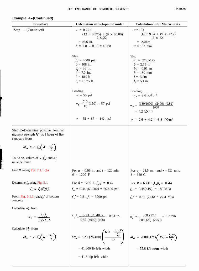
FIRE ENDURANCE OF CONCRETE ELEMENTS 216R-33
Example 4-(Continued)
Procedure
Step 1-(Continued)
Step 2-Determine positive nominalmoment strength A4,id at 3 hours of fireexposure from
M;” = A&(d -$)
To do so, values of 0, & and a;must be found
Find H, using Fig. 7.1.1 (b)
Determine fy0- using Fig. 5. 1
A, = .f, u;.,!f?
From Fig. 6.1.1 readf,, of bottomconcrete
Calculate a+0- from
4fwa+0- =_
0.85x.,‘b
Calculate nl;, from
M,;, = A,j;(d - %)
Calculation in inch-pound units
u = 0.75 +(13 x 0.375) + (9 x 0.500)
2 x 22= 0.96 in.
d = 7.0 - 0.96 = 6.0 in
Slabf,,’ = 4000 psib = 108 in.b, = 36 in.h = 7.0 in.l = 18.0 ftl,, = 16.75 ft
LoadingW, = 55 psf
Wd = E (150) = 87 psf
w = 55 + 87 = 142 psf
For u = 0.96 in. and t = 120 min.0 = 1200 F
For 8 = 1200 F, j;,if, = 0.44
t, = 0.44 (60,000) = 26,400 psi
f;.,’ = 0.81 Jo,’ = 3200 psi
a + _ 3.23 (26,400) = 0.23 in.I, =’0.85 (4000) (108)
IV,;@ = 3.23 (26,400)
= 41,800 lb-ft/ft width
= 41.8 kip-ft/ft width
Calculation in SI Metric units
u = 19+(13 x 9.5) + (9 x 12.7)
2 x 22= 24mm
d = 152 mm
Slabf’ = 27.6MPab = 2.75 mbE = 0.91 mh = 180 mml = 5.5mln = 5. 1 m
LoadingW, = 2.6 kN/m’
Wd =(180/1000) (2400) (9.81)
1000= 4.2 kN/m?
w = 2.6 + 4.2 = 6.8 kN/m’
For u = 24.5 mm and t = 120 min.0 = 650 C
For 0 = 65O C, &.Jfy = 0.44
f;., = 0.44(410) = 180 MPa
f’LH ’ = 0.81 (27.6) = 22.4 MPa
a’ =P2080(178) = 5.7 mm
0.85 (28) (2750)
/VI;,, = 2080(17X)(152 - y)
= 55.8 kN-m/m width
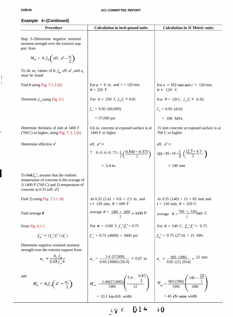
216R-34 ACI COMMITTEE REPORT
Example 4-(Continued)
Procedure
Step 3-Determine negative nominalmoment strength over the exterior sup-port from
M,,, = A,&, eff. d’ - 2>
To do so, values of 0, &, eff. d’, and CI”must be found
Find 8 using Fig. 7.1. 1 (b)
Determine:.f;, using Fig. 5.1
Calculation in inch-pound units
Foru = 6 in. and t = 120 min.0 = 250 F
For H = 250 F, .f;,(f, = 0.95
f,, = 0.95 (60,000)
= 57,000 psi
0.6 in. concrete at exposed surface is at1400 F or higher
eff. d’ =
7 0 - 0 . 6 - 0 . 7 5 - 1- o.500+o.3752 ( 2 >
= 5.4 in.
At 0.35 (5.4) + 0.6 = 2.5 in. andt = 120 min, 8 = 600 F
average 0 = 1400 + 600 = 1000 F2
For 0 = 1100 F, A,‘$.’ = 0.75
fi,,’ = 0.75 (4000) = 3000 psi
a- = 1.4 (57,000)” = 0.87 in.
0.85 (3000) (36.0)
54-0.87Mm = 1.40(57,000) . 2
)I# 1000 ( >12
= 33.1 kip-ft/ft width
Calculation in SI Metric units
Determine thickness of slab at 1400 F(760 C) or higher, using Fig. 7. 1. 1 (b)
Determine effective d’
To hndf;“‘, assume that the realistictemperature of concrete is the average ofI) 1400 F (760 C) and 2) temperature ofconcrete at 0.35 (eff. d')
Find 2) using Fig. 7.1.1 (b)
Find average 0
From Fig. 6.1.1
Determine negative nominal momentstrength over the exterior support from
and
Forlr = 152mmandt = 120 min,N= 120 C
For H = 120 C, .f;,/j; = 0.95
t;.,, = 0.95 (410)
= 390 MPa
15 mm concrete at exposed surface is at760 C or higher
eff. d’ =
180_ ,5_ ,+; (12.72+= )= 140 mm
At 0.35 (140) + 15 = 65 mm andt = 120 min, 8 = 320 C
average 760 + 320-0 =
- _ 540 C2
For 0 = 540 C, f,.,,‘$’ = 0.75
f;.,,’ = 0.75 (27.6) = 21 MPa
u; = 903 (390) = 22 mm0.85 (21) (914)
140 - 22M 903 (390)
i
2=ll# 1000 1000 1= 45 kN-m/m width
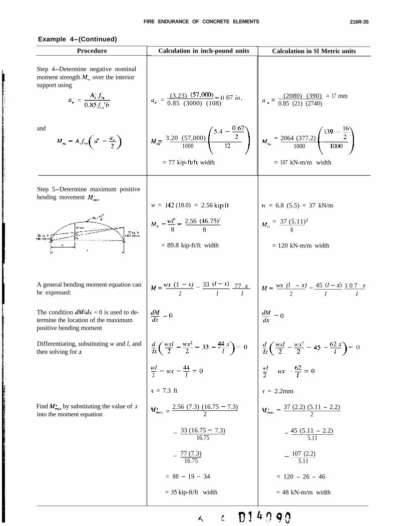
FIRE ENDURANCE OF CONCRETE ELEMENTS 216R-35
Example 4-(Continued)
Procedure
Step 4-Determine negative nominalmoment strength IV,,,, over the interiorsupport using
a~ = AX,B o.xsf;,,‘l?
and
Step 5-Determine maximum positivebending movement M;;(,,
A general bending moment equation canbe expressed:
The condition dMldx = 0 is used to de-termine the location of the maximumpositive bending moment
Differentiating, substituting w and l, andthen solving for x
Find M;, by substituting the value of xinto the moment equation
Calculation in inch-pound units
(1” =(3.23) (57,000) = 0 67 in
0.85 (3000) (108) . .
M = 3.20 (57,000)NH 1000
= 77 kip-ft/ft width
w = 142 (18.0) = 2.56 kipift
M = u’l? = 2.56 (16.75)?0
8 8
= 89.8 kip-ft/ft width
M = WX (1 - x) _ 33 (1 - x) 77 x2 l l
dx = 0dY
Wl_-2
wx-44=()l
x = 7.3 ft
%<U =2.56 (7.3) (16.75 - 7.3)
2
33 (16.75 - 7.3)_16.75
_ 77 (7.3)16.75
= 88 - 19 - 34
= 35 kip-ft/ft width
Calculation in SI Metric units
N ,, =(2080) (390) = 17 mm
0.85 (21) (2740)
M = 2064 (377.2),111 1000
= 107 kN-m/m width
\I’ = 6.8 (5.5) = 37 kN/m
M = 37 (5.11)2
08
= 120 kN-m/m width
M = wx (l - x) _ 45 (1 - x) 1 0 7 .r2 1 1
dA = 0dr
K = 2.2mm
~,:,o, = 37 (2.2) (5.11 - 2.2)2
_ 45 (5.11 - 2.2)5.11
- 107 (2.2)5.11
= 120 - 26 - 46
= 48 kN-m/m width
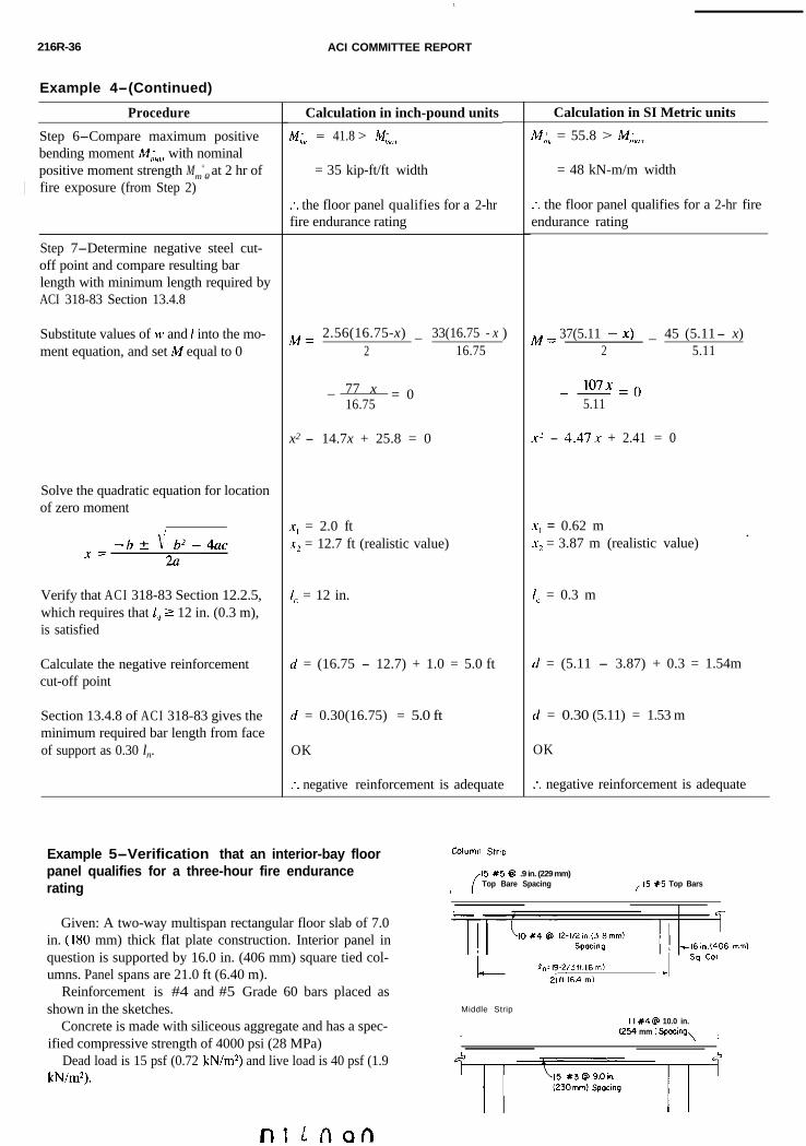
216R-36 ACI COMMITTEE REPORT
1
Example 4-(Continued)
Procedure
Step 6-Compare maximum positivebending moment y;,,, with nominalpositive moment strength Mm
+0- at 2 hr of
) fire exposure (from Step 2)
Step 7-Determine negative steel cut-off point and compare resulting barlength with minimum length required byACI 318-83 Section 13.4.8
Substitute values of w and 1 into the mo-ment equation, and set M equal to 0
Solve the quadratic equation for locationof zero moment
Verify that ACI 318-83 Section 12.2.5,which requires that I,, 2 12 in. (0.3 m),is satisfied
Calculate the negative reinforcementcut-off point
Section 13.4.8 of ACI 318-83 gives theminimum required bar length from faceof support as 0.30 ln.
Calculation in inch-pound units
M,:, = 41.8 > MC,<,,
= 35 kip-ft/ft width
:. the floor panel qualifies for a 2-hrfire endurance rating
M = 2.56(16.75-x) _ 33(16.75 - x2 16.75
_ 77 x = 016.75
x2 - 14.7x + 25.8 = 0
x, = 2.0 ft,rZ = 12.7 ft (realistic value)
I, = 12 in.
d = (16.75 - 12.7) + 1.0 = 5.0 ft
rf = 0.30(16.75) = 5.0 ft
OK
. negative reinforcement is adequate. .
)
Calculation in SI Metric units
M:,” = 55.8 > M;,<,,
= 48 kN-m/m kN-m/m width
:. the floor panel qualifies for a 2-hr fireendurance rating
M = 37(5.11 -X) _ 45 (5.11 - x)2 5.11
107x -- -= 05.11
x2 - 4.47x + 2.41 = 0
x, = 0.62 m .x2 = 3.87 m (realistic value)
Id = 0.3 m
d = (5.11 - 3.87) + 0.3 = 1.54m
d = 0.30 (5.11) = 1.53 m
OK
:. negative reinforcement is adequate
Example 5-Verification that an interior-bay floorpanel qualifies for a three-hour fire endurancerating
Given: A two-way multispan rectangular floor slab of 7.0in. (180 mm) thick flat plate construction. Interior panel inquestion is supported by 16.0 in. (406 mm) square tied col-umns. Panel spans are 21.0 ft (6.40 m).
Reinforcement is #4 and #5 Grade 60 bars placed asshown in the sketches.
Concrete is made with siliceous aggregate and has a spec-ified compressive strength of 4000 psi (28 MPa)
Dead load is 15 psf (0.72 kN/m*) and live load is 40 psf (1.9kN/m*).
Column Strip
15 x5 @I .9 in. (229 mm)Top Bare Spacing
/I5 X5 Top Bars
Middle StripI I #4 @ 10.0 in.
I (254 mm ) Spacing, ,
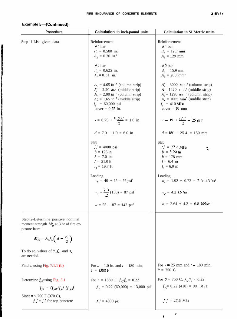
FIRE ENDURANCE OF CONCRETE ELEMENTS 216R-37
Example 5-(Continued)
Procedure
Step 1-List given data
Step 2-Determine positive nominalmoment strength M;# at 3 hr of fire ex-posure from
To do so, values of 8, f,,, and u;are needed.
Find 8, using Fig. 7.1.1 (b)
Determine fy0- using Fig. 5.1
f y0- = ( f y0- / f y) ( f y0- )
Since 0 < 700 F (370 C),f,.,’ = i ’ for top concrete
Calculation in inch-pound units
Reinforcement#4 bardh = 0.500 in.Ab = 0.20 in.2
#5 bar(i,, = 0.625 in.A,? = 0.31 in.2
A,,- = 4.65 in.z (column strip)As
- = 2.20 in.2 (middle strip)A: = 2.00 in.* (column strip)A: = 1.65 in.2 (middle strip)fy = 60,000 psicover = 0.75 in.
14 = 0.75 + y = 1.0 in
d = 7.0 - 1.0 = 6.0 in.
Slab1;.’ = 4000 psib = 126 in.h = 7.0 in.I = 21.0 ft1,) = 19.7 ft
Loading Loading‘V, = 40 + 15 = 55 psf w, = 1.92 + 0.72 = 2.64kN/m?
*1’</ = 2 (150) = 87 psf
w = 55 + 87 = 142 psf
-
For 11 = 1.0 in. and r = 180 min,H = 1380 F
For 0 = 1380 F, fy0- /fy = 0.22
j;,,, = 0.22 (60,000) = 13,000 psi
,fl,,’ = 4000 psi
Calculation in SI Metric units
Reinforcement#4 barcl,, = 12.7mmAb = 129 mm
#5 bardb
= 15.9 mm
Ab = 200 mmz
As- = 3000 mmL (column strip)
= 1420 mm2 (middle strip)As
+ = 1290 mm’ (column strip)A: = 1065 mm? (middle strip)fy = 410 MPacover = 19 mm
U= 19+E=25mm2
d = 180 - 25.4 = 150 mm
SlabJ;,’ = 27.6 MPab = 3.20mh = 178 mml = 6.4 mln = 6.0 m
WC/ = 4.2 kN/mL
CIJ = 2.64 + 4.2 = 6.8 kN/m?
For II = 25 mm and t = 180 min,H = 750 C
For 6, = 750 C, = 0.22
f y0- = 0.22 (410) = 90 MPa
f;,,,’ = 27.6 MPa
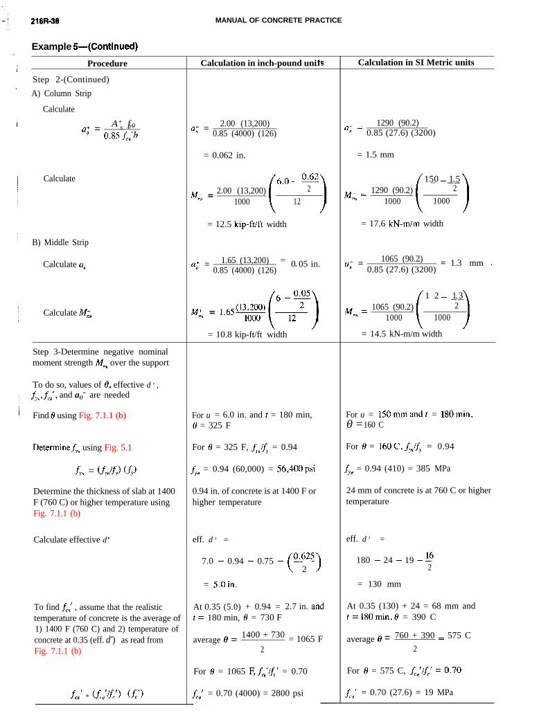
MANUAL OF CONCRETE PRACTICE216R-38
Example 5-(Continued)
Calculation in SI Metric unitsCalculation in inch-pound uniProcedure
Step 2-(Continued)
A) Column Strip
Calculate
a+ = 1290 (90.2)0 0.85 (27.6) (3200)
= 1.5 mm
a+ =A+
s f y0-0 0.85 fco’b
a; = 2.00 (13,200)0.85 (4000) (126)
= 0.062 in.
( 150- _ _1 . _52
1000
6.0 _ O*”2.00 (13,200) 2
M,', =1000 12
Calculate
M&=A;f,(d-%)1290 (90.2)M,‘, =
1000
= 17.6 kN-m/m width= 12.5 kip-ft/ft width
B) Middle Strip
Calculate a; a; = 1065 (90.2) = 1.3 mm ,0.85 (27.6) (3200)
a; = 1.65 (13,200) = 0 05 in. ’0.85 (4000) (126)
M;, = 1.65%1065 (90.2)Mio =
1000 ( 152 - _1 ._32
1000
= 10.8 kip-ft/ft width = 14.5 kN-m/m width
Calculate M,:,
Step 3-Determine negative nominalmoment strength M,-, over the support
To do so, values of 0, effective d’,
&I3 f9 /, and a0- - are needed
Find 8 using Fig. 7.1.1 (b) For u = 150mmandt = 180min,0- =160 C
For u = 6.0 in. and t = 180 min,8 = 325 F
For 0 = 16OC, fyHlfy = 0.94For 0 = 325 F, hOlfy = 0.94Determine&@ using Fig. 5.1
fye = 0.94 (410) = 385 MPafye = 0.94 (60,000) = 56,400psifye = (f,,lf,) U-J
24 mm of concrete is at 760 C or highertemperature
Determine the thickness of slab at 1400F (760 C) or higher temperature usingFig. 7.1.1 (b)
0.94 in. of concrete is at 1400 F orhigher temperature
eff. d’ =
7.0 - 0.94 - 0.75 -(EK
2 I
eff. d’ = “Calculate effective d’
180 - 24 - 19 - 162
= 130 mm= 5.0in.
At 0.35 (130) + 24 = 68 mm andt = 180min, 8 = 390 C
At 0.35 (5.0) + 0.94 = 2.7 in. art = 180 min, 8 = 730 F
nd
F
To find f,,' , assume that the realistictemperature of concrete is the average of1) 1400 F (760 C) and 2) temperature ofconcrete at 0.35 (eff. d') as read fromFig. 7.1.1 (b)
1400 + 730 average 8 = 760 + 390 = 575 C
2= 10658 =average
2
For 8 = 575 C, f,,‘lf,’ = 0.70For 8 = 1065 F, fccr’lfcl = 0.70
fI
ce= 0.70 (27.6) = 19 MPaf
I
CO= 0.70 (4000) = 2800 psifc0- f = (f,,‘lfc’> <f,‘>
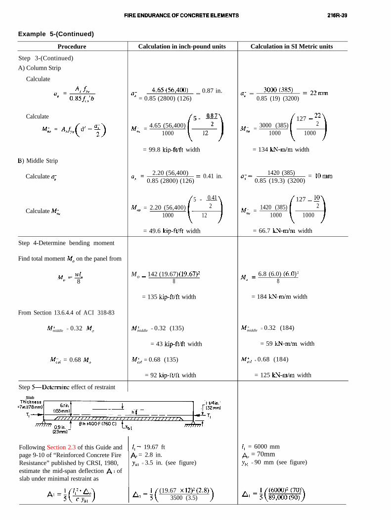
Example 5-(Continued)
Procedure
Step 3-(Continued)
A) Column Strip
Calculate
A-fa; = s YO
0.85f,,'b
Calculate
Mn, = A&(d’ - %)
) Middle Strip
Calculate a,-
Calculate M;@
Step 4-Determine bending moment
Find total moment MO on the panel from
=!!!LMo 8
From Section 13.6.4.4 of ACI 318-83
M'middle = 0.32 MO
WOl = 0.68 MO
Calculation in inch-pound units
4*65 (56~400)aB = 0.85 (2800) (126)
= 0.87 in.
M, = 4.65 (56,400)1000
5 - _0 ._8 _72
= 99.8 kip-ft/ft width
a; = 2.20 (56,400)0.85 (2800) (126) =
0.41 in.
_0_. _4 _15 -2M, 2.20= (56,400)
1000 12
= 49.6 kip-ft/ft width
Mo 142 (19.67) (19.67)*- MO = 6.8 (6.0) (6.0)*8 8
= 135 kip-ft/ft width
M'middle = 0.32 (135)
= 43 kip-ft/ft width
M,‘,, = 0.68 (135)
= 92 kip-ft/ft width
Step 5-Determine effect of restraint
Slab
(23mm)
Following Section 2.3 of this Guide and I I, = 19.67 ftpage 9-10 of “Reinforced Concrete FireResistance” published by CRSI, 1980,estimate the mid-span deflection -̂ 1 ofslab under minimal restraint as
-̂0 = 2.8 in.
Ybl = 3.5 in. (see figure)
-̂ 1
(19.67 x 12)*(2.8)3500 (3.5)
Calculation in SI Metric units
M, = 3000 (385)1000
127 - 222
1000
a; =3ooo (385) = 22 mm
0.85 (19) (3200)
= 134 kN-m/m width
127 - 10’1420 (385) 2
M, =1000 1000
1420 (385)a’ = 0.85 (19.3) (3200)
= 1Omm
= 66.7 kN-m/m width
= 184 kN-m/m width
M'middle = 0.32 (184)
= 59 k-N-m/m width
M,‘,l = 0.68 (184)
= 125 kN-m/m width
I, = 6000 mm
-̂ 0= 70mm
Ybl = 90 mm (see figure)
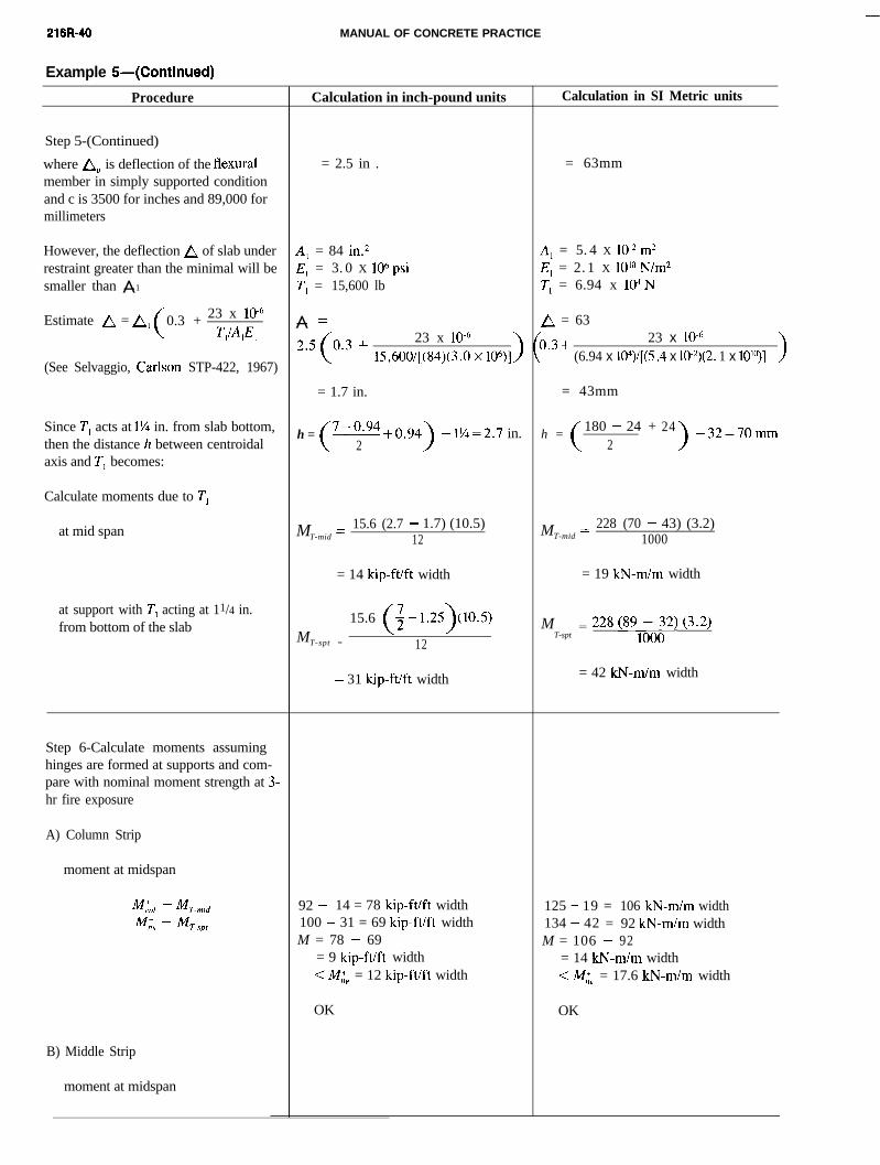
-XI
216R-40 MANUAL OF CONCRETE PRACTICE
Example 5-(Continued)
Procedure
Step 5-(Continued)
where A, is deflection of the flexuralmember in simply supported conditionand c is 3500 for inches and 89,000 formillimeters
However, the deflection A of slab underrestraint greater than the minimal will besmaller than -̂ 1
Estimate A = A, 0.3 + 23 x 1O-6
T,~f%E, >
(See Selvaggio, Carlso n STP-422, 1967)
Since Tl acts at 1% in. from slab bottom,then the distance h between centroidalaxis and T, becomes:
Calculate moments due to T,
at mid span
at support with Tl acting at 11/4 in.from bottom of the slab
Step 6-Calculate moments assuminghinges are formed at supports and com-pare with nominal moment strength at 3-hr fire exposure
A) Column Strip
moment at midspan
M~01 - MT-mid
M, - MT-spt
B) Middle Strip
moment at midspan
Calculation in inch-pound units
= 2.5 in .
Al = 84 in.2
E, = 3. 0 X 106psiTl = 15,600 lb
-̂ -23 x lo-”
15,600/[(84)(3. 0 x 106)] >
= 1.7 in.
h = 7-0.94.0.94>
- 1%=2. 7 in.2
MT-mid =15.6 (2.7 - 1.7) (10.5)
12
= 14 kip-ft/ft width
M15.6 (; - 1.25)(10.5)
T-spt = 12
= 31 kip-ft/ft width
92 - 14 = 78 kip-ft/ft width 125 - 19 = 106 kN-m/m width100 - 31 = 69 kip-ft/ft width 134 - 42 = 92 kN-m/m widthM = 78 - 69 M = 106 - 92
= 9 kip-ft/ft width = 14 kN-m/m width
< M,‘, = 12 kip-ft/ft width < M,‘, = 17.6 kN-m/m width
OK
Calculation in SI Metric units
= 63mm
Al = 5. 4 X lO-2 m2E, = 2. 1 X lOlo N/m2
T, = 6.94 x 10⁴N
/\ = 63
b.3+ 23 x lO-6
\ (6.94 x 10⁴)/[(5 .4 x 10-2)(2 . 1 x lOlo)] >
= 43mm
h = 180 - 24 + 24>
-32=70mm2
MT-mid =228 (70 - 43) (3.2)
1000
= 19 kN-m/m width
MT-spt
= 228 (891;o;2) c302)
= 42 kN-m/m width
OK
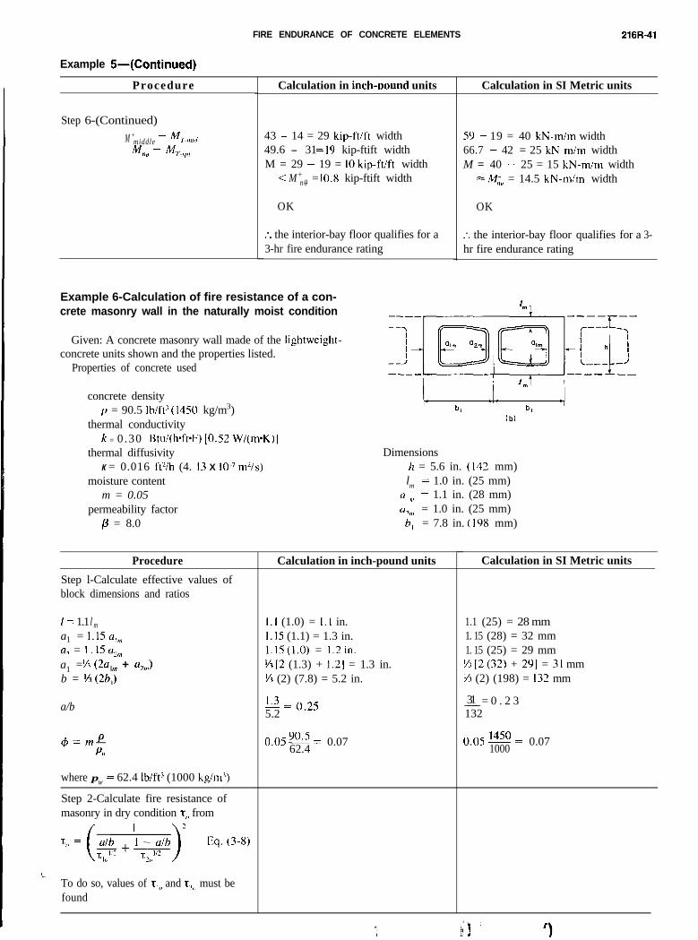
FIRE ENDURANCE OF CONCRETE ELEMENTS 216R-41
Iml
Example 6-Calculation of fire resistance of a con-crete masonry wall in the naturally moist condition
Given: A concrete masonry wall made of the lightweight-concrete units shown and the properties listed.
Properties of concrete used
concrete densityp = 90.5 Ib/ft’ (1450 kg/m3)
thermal conductivityk = 0.30 Btu/(h*fPF) [O.S2 W/(m*K)]
thermal diffusivityK = 0.016 ftYh (4. I3 X IO-’ m’is)
(bl
Dimensionsh = 5.6 in. (142 mm)
moisture contentm = 0.05
permeability factorp = 8.0
lm = 1.0 in. (25 mm)(I I ,,I = 1.1 in. (28 mm)
cI?,,t = 1.0 in. (25 mm)b, = 7.8 in. (198 mm)
Procedure
Step l-Calculate effective values ofblock dimensions and ratios
1 = 1.1 l ma1 = l.Ea,,,,a2 = I . I5 d2,>,a1 = %3 (2qm + a,,>)b = % (2bJ
a/b
$=mPPM
where pw = 62.4 Ib/fP (1000 kg/m’)
Step 2-Calculate fire resistance ofmasonry in dry condition t,, from
Calculation in inch-pound units
1.1 (1.0) = 1.1 in.I.15 (1.1) = 1.3 in.l.l5(1.0) = 1.2 in.ti [2 (1.3) + 1.21 = 1.3 in.fi (2) (7.8) = 5.2 in.
1.3 zzz () 255.2 .
0.05 90.5 = 0.0762.4
Calculation in SI Metric units
1.1 (25) = 28 mm1. 15 (28) = 32 mm1. 15 (25) = 29 mmfi [2(32) + 29] = 31 mmti (2) (198) = 132 mm
_ 3_1__ = 0 . 2 3132
0.05 1450 =1000
0.07
To do so, values of z,,, and L,, must befound
Example 5-(Continued)
Procedure
Step 6-(Continued)
M +middle - M~-,,l,dM& - MT,,,,
Calculation in inch-uound units
43 - 14 = 29 kip-ft/ft width 59 - 19 = 40 kN-m/m width49.6 - 3 1 = I9 kip-ftift width 66.7 - 42 = 25 kN-m/m widthM = 29 - 19 = IO kip-ft/ft width M = 40 - 25 = 15 kN-m/m width
< M+ n0- = = 10.8 kip-ftift width = M,;” = 14.5 kN-m/m width
OK OK
:. the interior-bay floor qualifies for a3-hr fire endurance rating
:. the interior-bay floor qualifies for a 3-hr fire endurance rating
Calculation in SI Metric units
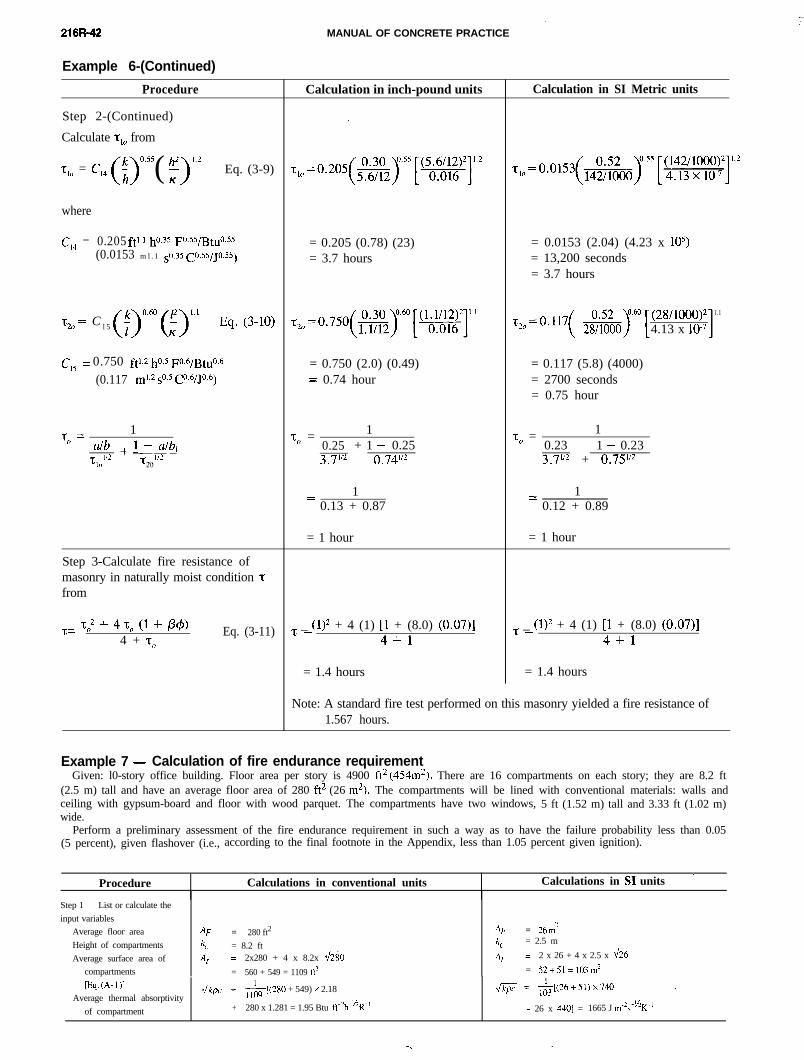
216R-42 MANUAL OF CONCRETE PRACTICE
Example 6-(Continued)
Procedure
Step 2-(Continued)
Calculate T,, from
T,, = C,, (;)“*s5 ( F)1’2 Eq. (3-9)
where
c,, = 0.205 ftl.1 ho.35 F0.55/BtU0.55
(0.0153 ml .1 ~0.35 CO.55/JO.55)
~2~ = C l 5 (f)‘*” (f)‘*’ Eq. (3-10)
Cl5= 0.750 ftl.2 ho.5 F0.6/Btu0.6
(0.117 rn102 s”e5 C”.6/Jo.6)
-co = 1a/b +l - a/b1
‘t l/210
-pT-20
Step 3-Calculate fire resistance ofmasonry in naturally moist condition ‘TIfrom
‘c = To2 + 4 To (1 + P@4 + To
Eq. (3-11)
Calculation in inch-pound units
= 0.205 (0.78) (23)= 3.7 hours
= 0.750 (2.0) (0.49)- 0.74 hour-
1To =0.253.7’12
+ 1 - 0.250.74’12
1--0.13 + 0.87
= 1 hour
z _ (1)2 + 4 (1) [I + (8.0) (0.07)]-4+1
= 1.4 hours
Calculation in SI Metric units
= 0.0153 (2.04) (4.23 x 10⁵)= 13,200 seconds= 3.7 hours
.G20=o.l17 ( &%J~6o [(28/looo)24.13 x lo-7 I 1.1
= 0.117 (5.8) (4000)= 2700 seconds= 0.75 hour
1To =0.23 1 - 0.233.7’12 + 0.751f2
1--0.12 + 0.89
= 1 hour
z _ (1)2 + 4 (1) [l + (8.0) (0.07)]-4+1
= 1.4 hours
Note: A standard fire test performed on this masonry yielded a fire resistance of1.567 hours.
Example 7 - Calculation of fire endurance requirementGiven: l0-story office building. Floor area per story is 4900 ft* (454m*). There are 16 compartments on each story; they are 8.2 ft
(2.5 m) tall and have an average floor area of 280 ft* (26 m*). The compartments will be lined with conventional materials: walls andceiling with gypsum-board and floor with wood parquet. The compartments have two windows, 5 ft (1.52 m) tall and 3.33 ft (1.02 m)wide.
Perform a preliminary assessment of the fire endurance requirement in such a way as to have the failure probability less than 0.05(5 percent), given flashover (i.e., according to the final footnote in the Appendix, less than 1.05 percent given ignition).
Procedure Calculations in conventional units Calculations in SI units ’
Step 1 - List or calculate the
input variables
Average floor area
Height of compartments
Average surface area of
compartments
AF = 280 ft2 AF = 26m’
h, = 8.2 ft h, = 2.5 m
A, 2x280 + 4 x 8.2x dzi 4 == 2 x 26 + 4 x 2.5 x d%
= 560 + 549 = 1109 ft2 = 52+51= 103m2
Eq. (A- 1 >IAverage thermal absorptivity
-Jkpc= &,(280 + 549) x 2.18
of compartment + 280 x 1.281 = 1.95 Btu ft-2h-I/‘R-’
d&SF = &(26+51)x740 .
+ 26 x 4401 = 1665 J m-2s-“K-’
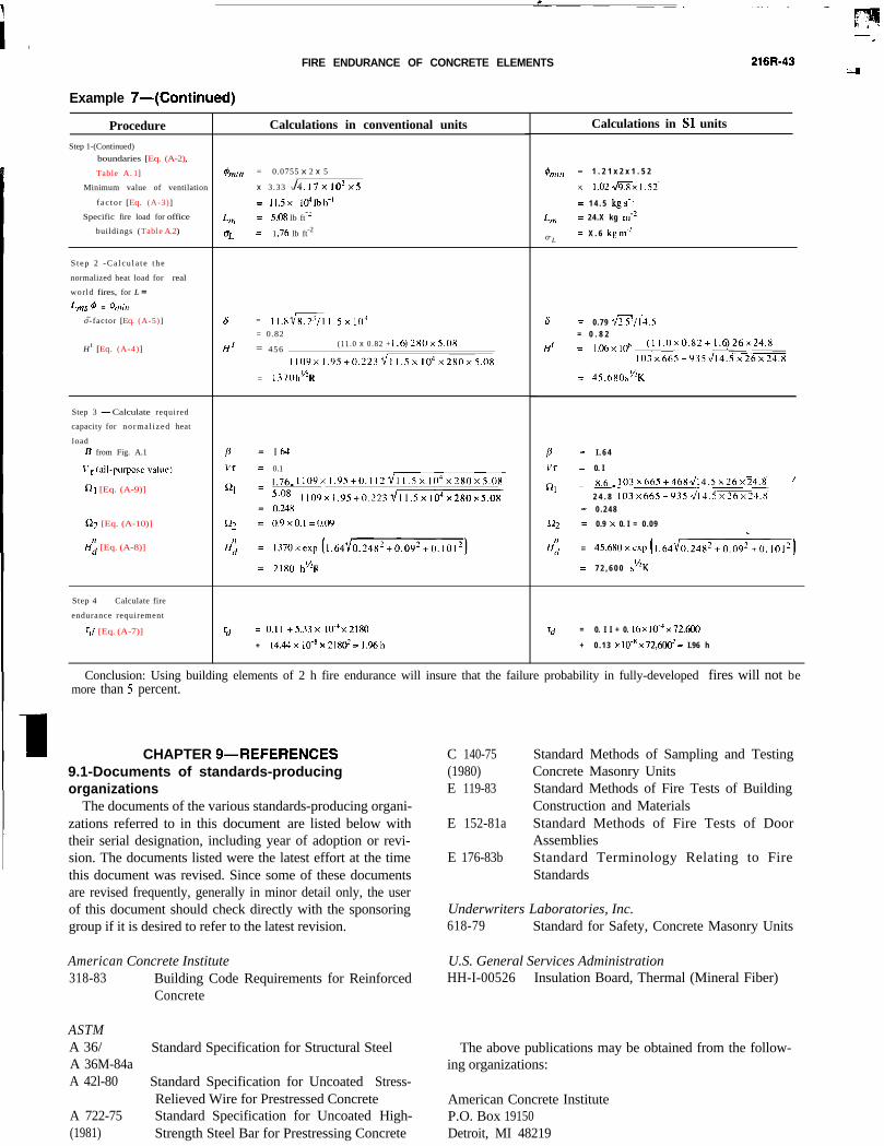
FIRE ENDURANCE OF CONCRETE ELEMENTS 216R-43
Example 7-(Continued)
Procedure
Step 1-(Continued)
boundaries [Eq. (A-2),
Table A. 1]
Minimum value of ventilation
f a c t o r [Eq. (A-3)]
Specific fire load for office
buildings (Table A.2)
S t e p 2 - C a l c u l a t e t h e
normalized heat load for real
world fires, for L =
L,,,, d = %Wl
o\~-factor [Eq. (A-5)]
Ht [Eq. (A-4)]
Step 3 - Calculate required
capacity for no rma l i zed heat
load6 from Fig. A.1
\‘~(all-purpose value)
Qt [Eq. (A-9)]
02 [Eq. (A-10)]
H:; [Eq. (A-8)]
Step 4 - Calculate fire
endurance requirement
r</ [Eq. (A-7)]
Calculations in conventional units
hilmin = 0.0755 x 2 x 5
x 3.33 \/4.17xlO’x5
= 11.5 x 1041bh-’
L??, = 5.0X lb ft-’
CL = 1 .76 lb ft-2
6 = Il.XGsl 1.5x IO= 0.82
H' = 4 5 6 (11.0 x 0.82 + 1.6)2x0x5.0X
l10YxI.‘~5+0.223~II.Sx104x2XOx5.0X
= 1370hHR
0.1
1 . 7 6 . 1 1 0 9 x 1 . 9 5 + 0 . 1 1 2 ~ 1 1 . 5 x 1 0 ’ x 2 x 0 x 5 . 0 8
5.08 l109x1.95+0.223’/ll.5x104x280x5.080.24u
2180 h”R
v = O.II +5.33x W”x2180
+ 14.44x10-8x21RtI?=1.96h
Calculations in SI units
$ml,, = 1 . 2 1 x 2 x 1 . 5 2
x 1.02~9.xx1.52
= 1 4 . 5 kgs-’
&I = 24.X kg III-’
o- L= X . 6 kg ,,I-’
6 = 0.79 VWZG= 0 . 8 2
H’= ,,06xIoh(11.0x0.X2+1.6)26x24.X
103x665+935~314.5x26x24.8
= 45.hXO>“K
P =1’1 =
cl1 =
=
Q2 =
H’:I =
=
I . 6 4
0. I
~~103x665+468~14.5x26x24.8 ’
2 4 . 8 103~665+935~.5~26~24.X
0 . 2 4 8
0.9 x 0. I = 0.09 l
7 2 , 6 0 0 >“K
Td = 0. I I + 0. I6 x WJ x 72.600
+ 0 . 1 3 x 10+x 72,60+= I.96 h
Conclusion: Using building elements of 2 h fire endurance will insure that the failure probability in fully-developed fires will not bemore than 5 percent.
CHAPTER 9--REFERENCES9.1-Documents of standards-producingorganizations
The documents of the various standards-producing organi-zations referred to in this document are listed below withtheir serial designation, including year of adoption or revi-sion. The documents listed were the latest effort at the timethis document was revised. Since some of these documentsare revised frequently, generally in minor detail only, the userof this document should check directly with the sponsoringgroup if it is desired to refer to the latest revision.
American Concrete Institute318-83 Building Code Requirements for Reinforced
Concrete
ASTMA 36/ Standard Specification for Structural SteelA 36M-84aA 42l-80 Standard Specification for Uncoated Stress-
Relieved Wire for Prestressed ConcreteA 722-75 Standard Specification for Uncoated High-(1981) Strength Steel Bar for Prestressing Concrete
C 140-75 Standard Methods of Sampling and Testing(1980) Concrete Masonry UnitsE 119-83 Standard Methods of Fire Tests of Building
Construction and MaterialsE 152-81a Standard Methods of Fire Tests of Door
AssembliesE 176-83b Standard Terminology Relating to Fire
Standards
Underwriters Laboratories, Inc.618-79 Standard for Safety, Concrete Masonry Units
U.S. General Services AdministrationHH-I-00526 Insulation Board, Thermal (Mineral Fiber)
The above publications may be obtained from the follow-ing organizations:
American Concrete InstituteP.O. Box 19150Detroit, MI 48219
21 6R-44 ACI COMMITTEE REPORT I .
ASTM1916 Race St.Philadelphia, PA 19103
Underwriters Laboratories, Inc.333 Pfingsten Rd.Northbrook, IL 60062
U.S. General Services AdministrationRegional Office
230 South Dearborn St.Chicago, IL 60604
9.2-Cited referencesAbrams , Melvin S., “Compressive Strength o f Concrete at Temperatures
to 1600F,” Temperature a n d Concrete, SP-25, American Concrete Institute,Detroit, 1971, pp. 33-58.
Abrams, M. S., and Cruz, Carlos R., “The Behavior at High Tem-perature of Steel Strand for PrestressPrestress Concrete,” Journal, PCA Research andDevelopment Laboratories, V. 3, No. 3, Sept. 1961, pp. 8-19. 8-19. Also, Re-search Department Bulletin No. 134, Portland Cement Association.
Abrams, M. S., and Gustaferro, A. H., “Fire Endurance of ConcreteSlabs as Influenced by Thickness, Aggregate Type, and Moisture," Journal,PCA Research and Development Laboratories, V. 10, No. 2, May 1968, pp.9-24. Also, Research Department Bulletin No. 223, Portland CementAssociation.
Abrams, M. S., and Gustaferro, A. H., “Fire Endurance of Two-CourseFloors and Roofs,” ACI JOURNAL, Proceedings V. 66, No. 2, Feb. 1969, pp.92-102.
Abrams, M. S.; Gustaferro, A. H.; and Salse, E. A. B., “Fire Tests ofConcrete Joist Floors and Roofs,” Research and Development Bul le t in No.RD006.01B, Portland Cement Association, Skokie, 1971, 25 pp.
Abrams, M. S., et al., “Fire Endurance of Continuous Reinforced Con-crete Beams,” Preliminary Report, 10th Congress of the International Asso-ciation for Bridge and Structural Engineering, Portland Cement Associa-tion, Skokie, 1976.
Allen, L. W., and Harmathy, T. Z., “Fire Endurance of Selected Con-crete Masonry Walls,” ACI JOURNAL, Proceedings V. 69, No. 9, Sept.1972, pp. 562-568.
American Institute of Steel Construction, Manual of Steel Construction,8th Edition, New York, 1980.
American Insurance Association, Fire Resistance Ratings, New York.Anderberg, Y., “Mechanical Properties of Reinforcing Steel at Elevated
Temperatures,” Tekniska Meddelande No. 36, Halmsted Jarnverk AB,Lund, 1978. (in Swedish)
ASTM E05.11 Task Group, “Repeatability and Reproducibility of Re-sults of ASTM E 119 Fire Tests,” Research Report No. RR: E5-1003,ASTM, Philadelphia, 1982.
Becker, James M., and Bresler, Boris, “Reinforced Concrete Frames inFire Environments,” Proceedings, ASCE, V. 103, ST1 Jan. 1977, pp.211-224.
Binner, C. R.; Wilkie, C. B.; and Miller, P., “Heat Testing of High Den-sity Concrete,” Declassified AEC Report No. HKF-1, U.S. Atomic EnergyCommission, Washington, D.C., June 1949.
Bresler, B., “Analytical Prediction of Structural Response to Fire,” FireSafety Journal, Sept. 1985, pp. 103-117.
Bresler, B., “Fire Protection of Modem Buildings: Engineering Re-sponse to New Problems,” 11th Annual Henry M. Shaw Lecture in Civil En-gineering, Department of Civil Engineering, North Carolina State Univer-sity, Raleigh, Jan. 1976.
Bresler, B., et al., “Limit State Behavior of Reinforced Concrete Framesin Fire Environments,” Proceedings, Regional Conference on Tall Build-ings, Hong Kong, Sept. 1976, pp. 310-325.
Brockenbrough, R. L., and Johnston, B. G., Steel Design Manual, U.S.Steel Corp., Pittsburgh, 1981, 253 pp.
Carlson, C. C.; Selvaggio, S. L.; and Gustaferro, A. H., “A Review ofStudies of the Effects of Restraint on the Fire Resistance of Prestressed Con-crete,” Proceedings, FIP Symposium on Fire Resistance of Prestressed Con-
crete (Braunschweig, 1965), Bauverlag GmbH, Wiesbaden, 1966, pp.32-42. Also, Research Department Bulletin No. 206, Portland CementAssociation.
Carman. A. D., and Nelson, R. A., “The Thermal Conductivity and Di-ffusivity of Concrete,” Bulletin No. 122, Engineering Experiment Station,University of Illinois, Urbana, Apr. 1921, 32 pp.
Cement and Concrete Association, “FIP/CEB Report on Methods of As-sessment of Fire Resistance of Concrete Structural Members,” PublicationNo. 15.393, Wexham Springs, 1978, 91 pp.
Cornell, C. Allin, “A Probability-Based Structural Code,” ACI JOURNAL
Proceedings V. 66, No. 12, Dec. 1969, pp. 974-985.Cruz, Carlos R., “Elastic Properties of Concrete at High Temperatures,”
Journal, PCA Research and Development Laboratories, V. 8, No. 1, Jan.1966, pp. 37-45. Also, Research Department Bulletin No. 191, Portland Ce-ment Association.
Cruz, Carlos R., “Apparatus for Measuring Creep of Concrete at HighTemperatures,” Journal, PCA Research and Development Laboratories, V.10, No. 3, Sept. 1968, pp. 36-42. Also, Research Department Bulletin No.225, Portland Cement Association.
Day, M. F.; Jenkinson. E. A.; and Smith, A. I., “Effect of Elevated Tem-peratures on High-Tensile Steel Wires for Prestressed Concrete,” Proceed-ings, Institution of Civil Engineers (London), V. 16, May 1960, pp. 55-70.
Dettling, Heinz, “The Thermal Expansion of Hardened Cement Paste,Aggregates, and Concretes (Die Warmedehnung des Zementsteines, derGesteine und der Betone),” Bulletin No. 164, Deutscher Ausschuss f
.u.. r
Stahlbeton, Berlin, 1964, Part 2, pp. l-64. Also, English translation, For-eign Literature Study No. 458, Portland Cement Association.
“DIN 19230, Structural Fire Protection in Industrial Building Construc-tion. part 1: Required Fire Resistance Period; Part 2: Determination of theBurning Factor m; Appendix 1 to Part 1: Calorific Value and m-Factors,”Draft in Manuscript Form, DIN Deutsches Institut f
.u. r Normung e.V.
Berlin, 1978.Dorn, J. E., “Some Fundamental Experiments on High-Temperature
Creep,” Journal of Mechanics, Physics, and Solids, V. 3, 1954, p. 85.ECCS-See European Convention for Constructional Steelwork.Ehm, H., and van Postel, R., “ Tests of Continuous Reinforced Beams
and Slabs Under Fire,” Proceedings, Symposium on Fire Resistance ofPrestressed Concrete, English translation, SLA Translation Center, JohnCrerar Library, Chicago.
European Convention for Constructional Steelwork (ECCS) TechnicalCommittee 3, European Recommendations for the Fire Safety of Steel Struc-tures, Elsevier Scientific Publishing Co., New York, 1983, 106 pp.
Expanded Shale, Clay and Slate Institute, “Fire Resistance of ExpandedShale, Clay and Slate Concrete Masonry.” Information Sheet No. 14,Bethesda.
Garofalo, E.; Malenock. P. R.; and Smith, G. V., “The Influence of Tem-perature on the Elastic Constants of Some Commercial Steels,” Symposiumon Determination of Elastic Constants, STP- 129, ASTM, Philadelphia,1952.
Gustaferro, A. H.. “Temperature Criteria at Failure,” Fire Test Perform-ance, STP-464, ASTM, Philadelphia, 1970, pp. 68-84.
Gustaferro, Armand H., “Design of Prestressed Concrete for Fire Re-sistance,” Journal, Prestressed Concrete Institute, V. 18, No. 6. Nov.-Dec.1973. pp. 102-116.
Gustaferro, A. H., “How to Design Prestressed Concrete for a SpecificFire Endurance,” Introductory Report, 10th IABSE Congress (Tokyo 1976),International Association for Bridge and Structural Engineering, Ziirich,1976.
Gustaferro, A. H . , and Abrams, M. S., “Fire Tests of Concrete Two-WayJoist Floors.” Research and Development Bulletin No. RD007.01 B, Port-land Cement Association. Skokie, 1971, 10 pp.
Gustaferro, Armand H.; Abrams, Melvin S.; and Litvin. Albert, “FireResistance of Lightweight Insulating Concretes,” Lightweight Concrete,SP-29, American Concrete Institute, Detroit. 1971, pp. 161-180.
Gustaferro, A. H.; Abrams. M. S.: and Salse, E. A. B.. “Fire Resistanceof Prestressed Concrete Beams. Study C: Structural Behavior During FireTests,” Research and Development Department Bulletin No. RD009.01 B.Portland Cement Association. Skokie. 1971. 29 pp.
Gustaferro, Armand H.. and Martin, Leslie D., Design for Fire Re-sistance of Precast Prestressed Concrete, Prestressed Concrete Institute,Chicago, 1977. 81 pp.
Gustaferro, A. H., and Selvaggio. S. L., “Fire Endurance of Simply-
FIRE ENDURANCE OF CONCRETE ELEMENTS 216R-45
Supported Prestrcssed Concrete Slabs,” J o u r n a l Prestressed Concrete In-stitute, V. 12, No. 1, Feb. 1967. pp. 37-52. Also, Research Department Bul-letin No. 212, Portland Cement Association.
Harmathy, T. Z. “Variable State Methods of Measuring the ThermalProperties of Solids,” Journal ofApplied Physics, V. 35, No. 4, Apr. 1964.pp. 1190-1200.
Harmathy, T. Z., “A Comprehensive Creep Model,” ASME, Journal of Basic Engineering V. 89 (Series D), 1967a, pp. 496-502.
Harmathy, T. Z..“Deflection and Failure of Steel-Supported Floorsand Beams in Fire ,” Symposium on Fire Test Methods-Restraint and Smoke, STP-422, ASTM, Philadelphia, 1967b, pp. 40-62.
Harmathy, T. Z., “Thermal Performance of Concrete Masonry Walls inFire,” Fire Test Performance, STP-464. ASTM, Philadelphia, 1970a, pp. 209-243.
Harmathy, T. Z.. “Thermal Properties of Concrete at Elevated Tem-peratures,” Journal of Materials, V. 5, No. 1, Mar. 1970b, pp. 47-74.
Harmathy, T. Z,, “Design of Concrete Masonry Walls for Fire En-durance," Behavior of Concrete Under Temperature Extremes, SP-39,American Concrete Institute, Detroit, 1973, pp. 179-203.
Harmathy, T. Z., “Creep Deflection of Metal Beams in Transient Heating Processes. With Particular Reference to Fire,” Canadian Journal of CivilEngineering (Ottawa), June 1976.
Harmathy. T. Z.,, “The Fire Resistance Test and Its Relation to Real-World Fires,” Fire and Materials, V. 5, No. 3. Sept. 1981, Pp. 112-122. 1
Harmathy. T. Z., “Fire Severity: Basis of Fire Safety Design,” FireSafety of Structures, SP-80, American Concrete Institute, Detroit, 1983, pp.115-149.
Harmathy. T. Z.,“On the Equivalent Fire Exposure,” Fire and Mate-rials, V. II. No. 2. 1987, pp. 95-104.
Harmathy. T. Z., and Allen. L. W., “Thermal Properties of Selected Ma-sonry Unit Concretes.” ACI JOURNAL , Proceedings V. 70, No. 2, Feb.
1973, pp. 132-142.Harmathy, T. Z., and Berndt. J. E., “Hydrated Portland Cement and
Lightweight Concrete at Elevated Temperatures,” ACI JOURNAL, Proceed- ings V. 63. No. 1, Jan. 1966. pp. 93- 112.
Harmathy. T. Z., and Mehaffey, J. R.. “Design of Buildings for Pre-scribed Levels of Structural Fire Safety,” Fire Safety: Science and Engineer-ing, STP-882, ASTM, Philadelphia, 1985, pp. 160-175.
Harmathy. T. Z., and Mehaffey. J. R., “The Normalized Heat Load Con-cept and Its Use,” Fire Safety Journal, (Lausanne),V. 12, No. 1, 1987, pp. 75-81.
Harmathy, T. Z., and Oracheaki, E. W., “Equivalent Thickness of Con-crete Masonry Units,” Building Research Note, National Research Councilof Canada, Ottawa, June 1970.
H a r m a t h y , T. Z., and Stanzack, W. W., “Elevated- Temperature Tensile and Creep Properties of Some Structural and Prestress-ing Steels,” Fire Test Performance STP-464, ASTM, Philadelphia, 1970.pp 186-208.
Iding, R. H.; Bresler, B.; and Nizamuddin, E., “FIRES-T3-A Com-puter Program for the Fire Response of Structure, Thermal, 3-DimensionalVersion,” Report No. UCB-FRG 77-15, Department of Civil Engineering,University of California, Berkeley, 1977.
Iding, R. H., et al., “FIRES-RCII-A Computer program for the FireResponse of Structures-Reinforced Concrete Frames, Revised Version,”Report No. UCB-FRG 77-8, Department of Civil Engineering, Universityof California, Berkeley, 1977.
Iding, R. H., and Bresler, B., “Prediction of Fire Response of BuildingsUsing Finite Element Methods,” Proceedings, 3rd CETA/ASCE Con-ference on Computing in Civil Engineering, American Society of Civil En-gineers, New York, 1984.
Ingberg, S. H., “Tests of Severity of Building Fires,” NFPA Quarterly,V. 22, No. 1.1928, pp. 43-61.
Issen, L. A.; Gustaferro, A. H.; and Carlson, C. C., “Fire Tests of Con-crete Members: An Improved Method for Estimating Restraint Forces,” FireTest Performance, STP-464, ASTM, Philadelphia, 1970, pp. 153-185.
Kordina, K., and Schneider, U., “Zum mechanischen Verhalten vonNormalbeton unter instationarer Warmebeanspruchung,” BetonHerstellung und Verwendung (Dusseldorf), V. 25, No. 1, 1975, pp. 19-25.
Law, M., “A Relationship between Fire Grading and Building Designand Contents,” JFRO Fire Research Note No. 877, 1971, 43 pp.
Lie, T. T., “Calculation of Fire Resistance of Composite Floor and RoofSlabs,” Fire Technology, Feb. 1978.
Lie, T. T., and Allen, D. E., “Calculation of the Fire Resistance of Rein-forced Concrete Columns,” Technical Paper No. 378, Division of BuildingResearch, National Research Council of Canada, Ottawa.
Lie, T. T., and Allen, D. E., “Further Studies on the Fii Resistance ofReinforced Concrete Columns,” Technical Paper No. 416, Division ofBuilding Research, National Research Council of Canada, Ottawa.
Lie, T. T., and Harmathy, T. Z., “A Numerical Procedure to Calculate theTemperature of Protected Steel Columns Exposed to Fire,” Fire Study No.28 (NRCC 12535), Division of Building Research, National Research Coun-cil of Canada, Ottawa, 1972, 26 pp.
Lie, T. T., and Harmathy, T. Z., “Fire Endurance of Concrete-protectedSteel Columns,” ACI JOURNAL, Proceedings V. 71, No. 1, Jan. 1974, pp.29-32.
Lie, T. T.: Lin, T. D.; Allen, D. E.; and Abrams, M. S., “Fire Resistance of Reinforced Concrete Columns,” DBR Paper No. 1167, Division of Build-ing Research, National Research Council of Canada, Ottawa, Feb. 1984.
Lie, T. T.; Lin, T. D.; and McGrath, R., “Fire Tests on Reinforced Con-crete Columns,” DBR Internal Report No. 497, National Research Councilof Canada, Ottawa, 1985.
Lin, T. D., “Measured Temperatures in Concrete Beams Exposed toASTM E 119 Standard Fire,” Research and Development Report, PortlandCement Association, Skokie, 1985.
Lin, T. D., and Abrams, Melvin S.,, “Simulation of Realistic ThermalRestraint During Fire Test of Floors and Roofs,” Fire Safety of ConcreteStructures, SP-80, American Concrete Institute, Detroit, 1983, pp. l-68.
Lin, T. D.; Ellingwood, B .; and Piet, O.,, “Shear Behavior of ReinforcedConcrete Beams During Fires,” Research and Development Report, Port-land Cement Association, Skokie, 198.5.
Lin, T. D.; Gustaferro, A. H.; and Abrams, M. S., “Fire Endurance ofContinuous Reinforced Concrete Beams,”Research and Development Bul-letin No. RDO72.01B, Portland Cement Association, Skokie, 1981, 21 pp.
Magnusson, S. E., and Thelandersson, S., “Temperature-Time Curvesof Complete process of Fire Development. Theoretical Study of Wood FuelFires in Enclosed Spaces,” Acta Polytechnica Scandinavica (Stockholm),Civil Engineering and Building Construction Series No. 65, 1970, 181 pp.
Malhotra, H. L., “The Effect of Temperature on the CompressiveStrength of Concrete,” Magazine o f Concrete Research (London), V. 8, No.23, Aug. 1956. pp. 85-94.
Malhotra, H. L., Design of Fire-Resisting Structures, Chapman & Hall,New York, 1982,226 pp.
Mehaffey, J. R., and Harmathy, T. Z., “Assessment of Fire ResistanceRequirements,” Fire Technology, V. 17, No. 4, Nov. 1981, pp. 221-237.
Mehaffey, J. R., and Harmathy, T. Z., “Thermal Response of Compart-ment Boundaries to Fire,” Proceedings, 1st International Symposium onFire Safety Science, Gaithersburg, Oct. 1985, pp. 111-118.
Mukaddam, M., “Creep Analysis of Concrete at Elevated Tem-peratures,” ACI JOURNAL , Proceedings V. 71, No. 2, Feb. 1974, pp. 72-78.
Mukaddam, M. A., and Bresler, B., “Behavior of Concrete Under Vari-able Temperature and Loading,” Concrete for Nuclear Reactors, SP-34,American Concrete Institute, Detroit, 1972, pp. 771-797.
Nasser, Karim W., and Neville, Adam M., “Creep of Old Concrete atNormal and Elevated Temperatures,” ACI JOURNAL, Proceedings V. 64,No. 2, Feb. 1967, pp. 97-102.
Nizamuddin, Zuhayr, and Bresler, Boris, “Fire Response of ReinforcedConcrete Slabs,” Proceedings, ASCE, V. 105, ST8, Aug. 1979, pp.1653-1671.
Odeen, Kai, “Fire Resistance of Prestressed Concrete Double-T Units,”Civil Engineering and Building Construction Series No. 48, Acta Poly-technica Scandinavica, Stockholm, 1968,75 pp.
Pettersson, O., “The Connection between a Real Fire Exposure and theHeating Conditions According to Standard Fire Resistance Tests-with Spe-cial Application to Steel Structures, ” Bulletin No. 39, Division of StructuralMechanics and Concrete Construction, Lund Institute of Technology, 1975,
86 P P.Pettersson, Ove, “Theoretical Design of Fire Exposed Structures,” Bul-
letin No. 51, Division of Structural Mechanics and Concrete Construction,Lund Institute of Technology, 1976.
Pettersson. 0.; Magnusson. S. E.: and Thor, J.. “Fire Engineering De-sign of Steel Structures,” Publication No. 50. Swedish lnstitutc of SteelConstruction, Stockholm, 1976.
Philleo. Robert, “Some Physical Propcrtics of Concrete at High Tem-peratures,” ACI JOURNAL, Proceedings V. 54. No. 10, Apr. 1958, pp.857-864.
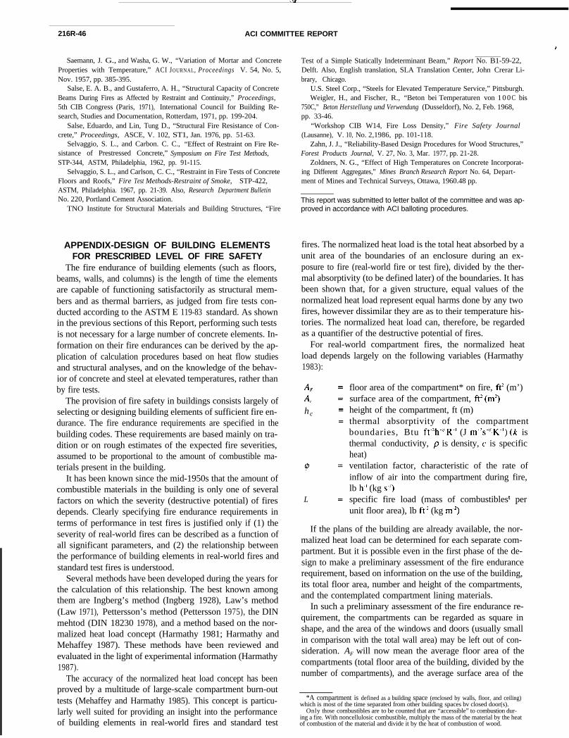
216R-46 ACI COMMITTEE REPORT
APPENDIX-DESIGN OF BUILDING ELEMENTSFOR PRESCRIBED LEVEL OF FIRE SAFETY
The fire endurance of building elements (such as floors,beams, walls, and columns) is the length of time the elementsare capable of functioning satisfactorily as structural mem-bers and as thermal barriers, as judged from fire tests con-ducted according to the ASTM E 119-83 standard. As shownin the previous sections of this Report, performing such testsis not necessary for a large number of concrete elements. In-formation on their fire endurances can be derived by the ap-plication of calculation procedures based on heat flow studiesand structural analyses, and on the knowledge of the behav-ior of concrete and steel at elevated temperatures, rather thanby fire tests.
The provision of fire safety in buildings consists largely ofselecting or designing building elements of sufficient fire en-durance. The fire endurance requirements are specified in thebuilding codes. These requirements are based mainly on tra-dition or on rough estimates of the expected fire severities,assumed to be proportional to the amount of combustible ma-terials present in the building.
It has been known since the mid-1950s that the amount ofcombustible materials in the building is only one of severalfactors on which the severity (destructive potential) of firesdepends. Clearly specifying fire endurance requirements interms of performance in test fires is justified only if (1) theseverity of real-world fires can be described as a function ofall significant parameters, and (2) the relationship betweenthe performance of building elements in real-world fires andstandard test fires is understood.
Several methods have been developed during the years forthe calculation of this relationship. The best known amongthem are Ingberg’s method (Ingberg 1928), Law’s method(Law 1971), Pettersson’s method (Pettersson 1975), the DINmehtod (DIN 18230 1978), and a method based on the nor-malized heat load concept (Harmathy 1981; Harmathy andMehaffey 1987). These methods have been reviewed andevaluated in the light of experimental information (Harmathy1987).
The accuracy of the normalized heat load concept has beenproved by a multitude of large-scale compartment burn-outtests (Mehaffey and Harmathy 1985). This concept is particu-larly well suited for providing an insight into the performanceof building elements in real-world fires and standard test
Saemann, J. G., and Washa, G. W., “Variation of Mortar and ConcreteProperties with Temperature,” ACI JOURNAL, Proceedings V. 54, No. 5,Nov. 1957, pp. 385-395.
Salse, E. A. B., and Gustaferro, A. H., “Structural Capacity of ConcreteBeams During Fires as Affected by Restraint and Continuity,” Proceedings,5th CIB Congress (Paris, 1971), International Council for Building Re-search, Studies and Documentation, Rotterdam, 1971, pp. 199-204.
Salse, Eduardo, and Lin, Tung D., “Structural Fire Resistance of Con-crete,” Proceedings, ASCE, V. 102, ST1, Jan. 1976, pp. 51-63.
Selvaggio, S. L., and Carbon. C. C., “Effect of Restraint on Fire Re-sistance of Prestressed Concrete,” Symposium on Fire Test Methods,STP-344, ASTM, Philadelphia, 1962, pp. 91-115.
Selvaggio, S. L., and Carlson, C. C., “Restraint in Fire Tests of ConcreteFloors and Roofs,” Fire Test Methods-Restraint of Smoke, STP-422,ASTM, Philadelphia. 1967, pp. 21-39. Also, Research Department BulletinNo. 220, Portland Cement Association.
TNO Institute for Structural Materials and Building Structures, “Fire
Test of a Simple Statically Indeterminant Beam,” Report No. B1-59-22,Delft. Also, English translation, SLA Translation Center, John Crerar Li-brary, Chicago.
U.S. Steel Corp., “Steels for Elevated Temperature Service,” Pittsburgh.Weigler, H., and Fischer, R., “Beton bei Temperaturen von 1 0 0 C bis
750C,” Beton Herstellung und Verwendung (Dusseldorf), No. 2, Feb. 1968,pp. 33-46.
“Workshop CIB W14, Fire Loss Density,” Fire Safety Journal(Lausanne), V. 10, No. 2,1986, pp. 101-118.
Zahn, J. J., “Reliability-Based Design Procedures for Wood Structures,”Forest Products Journal, V. 27, No. 3, Mar. 1977, pp. 21-28.
Zoldners, N. G., “Effect of High Temperatures on Concrete Incorporat-ing Different Aggregates,” Mines Branch Research Report No. 64, Depart-ment of Mines and Technical Surveys, Ottawa, 1960.48 pp.
This report was submitted to letter ballot of the committee and was ap-proved in accordance with ACI balloting procedures.
fires. The normalized heat load is the total heat absorbed by aunit area of the boundaries of an enclosure during an ex-posure to fire (real-world fire or test fire), divided by the ther-mal absorptivity (to be defined later) of the boundaries. It hasbeen shown that, for a given structure, equal values of thenormalized heat load represent equal harms done by any twofires, however dissimilar they are as to their temperature his-tories. The normalized heat load can, therefore, be regardedas a quantifier of the destructive potential of fires.
For real-world compartment fires, the normalized heatload depends largely on the following variables (Harmathy1983):
A,A,hc
4J
L
floor area of the compartment* on fire, ft’ (m’)surface area of the compartment, ft’ (m’)height of the compartment, ft (m)thermal absorptivity of the compartmentboundaries, Btu ft-‘hW”R-’ (J m?“‘:K”) (k isthermal conductivity, p is density, c is specificheat)ventilation factor, characteristic of the rate ofinflow of air into the compartment during fire,lb h-’ (kg s-‘)specific fire load (mass of combustiblest perunit floor area), lb ft’ (kg m-2)
If the plans of the building are already available, the nor-malized heat load can be determined for each separate com-partment. But it is possible even in the first phase of the de-sign to make a preliminary assessment of the fire endurancerequirement, based on information on the use of the building,its total floor area, number and height of the compartments,and the contemplated compartment lining materials.
In such a preliminary assessment of the fire endurance re-quirement, the compartments can be regarded as square inshape, and the area of the windows and doors (usually smallin comparison with the total wall area) may be left out of con-sideration. AF will now mean the average floor area of thecompartments (total floor area of the building, divided by thenumber of compartments), and the average surface area of the
*A compartment is defined as a building space (enclosed by walls, floor, and ceiling)which is most of the time separated from other building spaces bv closed door(s).
Only those combustibles are to be counted that are “accessible” to combustion dur-ing a fire. With noncellulosic combustible, multiply the mass of the material by the heatof combustion of the material and divide it by the heat of combustion of wood.
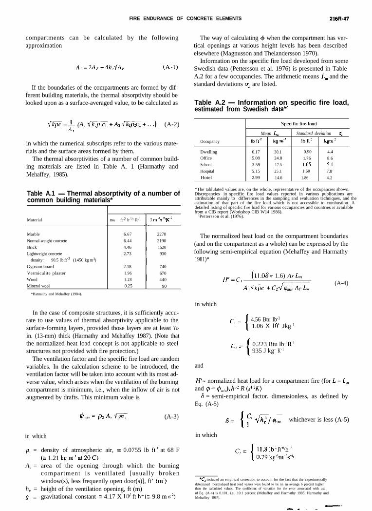
FIRE ENDURANCE OF CONCRETE ELEMENTS 216R-47
compartments can be calculated by the followingapproximation
A,=2Ar+4h,G (A-1)
If the boundaries of the compartments are formed by dif-ferent building materials, the thermal absorptivity should belooked upon as a surface-averaged value, to be calculated as
e=+ (A, =+A2 1/+...) (A-2)f
in which the numerical subscripts refer to the various mate-rials and the surface areas formed by them.
The thermal absorptivities of a number of common build-ing materials are listed in Table A. 1 (Harmathy andMehaffey, 1985).
Table A.1 - Thermal absorptivity of a number ofcommon building materials*
Material Btu ft-2 h-1/2 R-1
Marble
Normal-weight concrete
Brick
Lightweight concrete
density: 90.5 lb ft-3 (1450 kg rn-3)
Gypsum board
Vermiculite plaster
Wood
Mineral wool
6.67
6.44
4.46
2.73
2.18
1.96
1.28
0.25
*Hatmathy and Mehaffey (1984).
2270
2190
1520
930
740
670
440
90
In the case of composite structures, it is sufficiently accu-rate to use values of thermal absorptivity applicable to thesurface-forming layers, provided those layers are at least Yz-in. (13-mm) thick (Harmathy and Mehaffey 1987). (Note thatthe normalized heat load concept is not applicable to steelstructures not provided with fire protection.)
The ventilation factor and the specific fire load are randomvariables. In the calculation scheme to be introduced, theventilation factor will be taken into account with its most ad-verse value, which arises when the ventilation of the burningcompartment is minimum, i.e., when the inflow of air is notaugmented by drafts. This minimum value is
@t,,,, = px A v V-& (A-3)
in which
P, =
Av =
hv =g =
density of atmospheric air, E 0.0755 lb ft.‘ at 68 F(2 1.21 kgm.‘at20C)area of the opening through which the burningcompartment is ventilated [usually brokenwindow(s), less frequently open door(s)], ft’ (m’)height of the ventilation opening, ft (m)gravitational constant s 4.17 X 1 O5 ft h-’ (G 9.8 m s-‘)
in which
The way of calculating 4 when the compartment has ver-tical openings at various height levels has been describedelsewhere (Magnusson and Thelandersson 1970).
Information on the specific fire load developed from someSwedish data (Pettersson et al. 1976) is presented in TableA.2 for a few occupancies. The arithmetic means L, and thestandard deviations aL are listed.
Table A.2 - Information on specific fire load,estimated from Swedish data*,+
Occupancy
DwellingOffice
School
Hospital
Hotel
Mean L, Standard deviation qlb fi2 kg mm2 lb ft.’ kgm-’
6.17 30.1 0.90 4.4
5.08 24.8 1.76 8.6
3.59 17.5 1 .a5 5.15.15 25.1 1.60 7.8
2.99 14.6 1.86 4.2
*The tablulated values are, on the whole, representative of the occupancies shown.Discrepancies in specific fire load values reported in various publications areattributable mainly to differences in the sampling and evaluation techniques, and theestimation of that part of the fire load which is not accessible to combustion. Adetailed listing of specific fire load for various occupancies and countries is available from a CIB report (Workshop CIB W14 1986).
tPettersson et al. (1976).
The normalized heat load on the compartment boundaries(and on the compartment as a whole) can be expressed by thefollowing semi-empirical equation (Mehaffey and Harmathy1981)*
H’=C,(ll.OS+ 1.6) AFL,,
A,i?+%zG(A-4)
in which
c, = 4.56 Btu lb-1
1.06 X 10h Jkg-1
c, = 0.223 Btu lb- ’ R.’935 J kg- ’ K - 1
and
H’= normalized heat load for a compartment fire (for L = L,,,and # = #,,,;,,), h”’ R (ST)
6 = semi-empirical factor. dimensionless, as defined byEq. (A-5)
whichever is less (A-5)
*C, included an empirical correction to account for the fact that the experimentally determined normalized heat load values were found to be on an average 6 percent higher than the calculated values. The coefficient of variation for the error associated with useof Eq. (A-4) is 0.101, i.e., 10.1 percent (Mehaffey and Harmathy 1985; Harmathy and Mehaffey 1987).
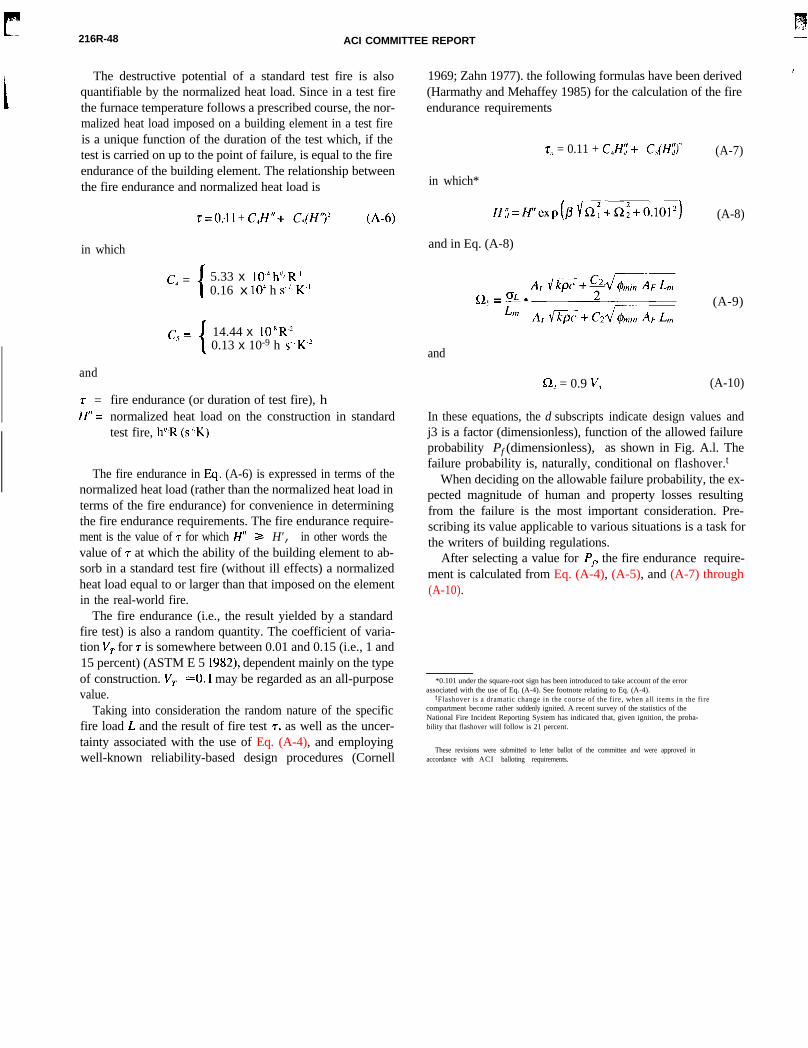
216R-48 ACI COMMITTEE REPORT
The destructive potential of a standard test fire is alsoquantifiable by the normalized heat load. Since in a test firethe furnace temperature follows a prescribed course, the nor-malized heat load imposed on a building element in a test fireis a unique function of the duration of the test which, if thetest is carried on up to the point of failure, is equal to the fireendurance of the building element. The relationship betweenthe fire endurance and normalized heat load is
in which
r= 0:ll + C,H"+ C,(H“)' (A-6)
c, = 5.33 x 1O-4 h”:R’0.16 x 10’ h s-“i K-’
and
r =H” =
c.< = 14.44 x lO~“R-’0.13 x 10⁻⁹ h s-l K.’
fire endurance (or duration of test fire), hnormalized heat load on the construction in standardtest fire, h”:R (s”.K)
The fire endurance in Eq . (A-6) is expressed in terms of thenormalized heat load (rather than the normalized heat load interms of the fire endurance) for convenience in determiningthe fire endurance requirements. The fire endurance require-ment is the value of r for which H" Z= H', in other words thevalue of r at which the ability of the building element to ab-sorb in a standard test fire (without ill effects) a normalizedheat load equal to or larger than that imposed on the elementin the real-world fire.
The fire endurance (i.e., the result yielded by a standardfire test) is also a random quantity. The coefficient of varia-tion VT for r is somewhere between 0.01 and 0.15 (i.e., 1 and15 percent) (ASTM E 5 1982), dependent mainly on the typeof construction. VT ~0.1 may be regarded as an all-purposevalue.
Taking into consideration the random nature of the specificfire load L and the result of fire test 7, as well as the uncer-tainty associated with the use of Eq. (A-4), and employingwell-known reliability-based design procedures (Cornell
1969; Zahn 1977). the following formulas have been derived(Harmathy and Mehaffey 1985) for the calculation of the fireendurance requirements
z, = 0.11 + C,H:;+ C,(H;)'
in which*
H:i=Ff’exp(fl~R:+Q:+O.lOl’)
and in Eq. (A-8)
and
R2 = 0.9 v, (A-10)
(A-7)
(A-8)
(A-9)
In these equations, the d subscripts indicate design values andj3 is a factor (dimensionless), function of the allowed failureprobability Pf (dimensionless), as shown in Fig. A.l. Thefailure probability is, naturally, conditional on flashover.t
When deciding on the allowable failure probability, the ex-pected magnitude of human and property losses resultingfrom the failure is the most important consideration. Pre-scribing its value applicable to various situations is a task forthe writers of building regulations.
After selecting a value for Pf, the fire endurance require-ment is calculated from Eq. (A-4), (A-5), and (A-7) through(A-10).
*0.101 under the square-root sign has been introduced to take account of the errorassociated with the use of Eq. (A-4). See footnote relating to Eq. (A-4).
tFlashover is a dramatic change in the course of the fire, when all items in the fire compartment become rather suddenly ignited. A recent survey of the statistics of theNational Fire Incident Reporting System has indicated that, given ignition, the proba-bility that flashover will follow is 21 percent.
These revisions were submitted to letter ballot of the committee and were approved inaccordance with ACI balloting requirements.