Embed Size (px)
DESCRIPTION
2223R_11
Citation preview

ACI 222.3R-11
Reported by ACI Committee 222
Guide to Design and ConstructionPractices to Mitigate Corrosion of
Reinforcement in Concrete Structures

Guide to Design and Construction Practices to Mitigate Corrosion of Reinforcement in Concrete Structures
First PrintingApril 2011
ISBN 978-0-87031-422-3
American Concrete Institute®
Advancing concrete knowledge
Copyright by the American Concrete Institute, Farmington Hills, MI. All rights reserved. This materialmay not be reproduced or copied, in whole or part, in any printed, mechanical, electronic, film, or otherdistribution and storage media, without the written consent of ACI.
The technical committees responsible for ACI committee reports and standards strive to avoid ambiguities,omissions, and errors in these documents. In spite of these efforts, the users of ACI documents occasionallyfind information or requirements that may be subject to more than one interpretation or may beincomplete or incorrect. Users who have suggestions for the improvement of ACI documents arerequested to contact ACI via the errata website at www.concrete.org/committees/errata.asp. Properuse of this document includes periodically checking for errata for the most up-to-date revisions.
ACI committee documents are intended for the use of individuals who are competent to evaluate thesignificance and limitations of its content and recommendations and who will accept responsibility for theapplication of the material it contains. Individuals who use this publication in any way assume all risk andaccept total responsibility for the application and use of this information.
All information in this publication is provided “as is” without warranty of any kind, either express or implied,including but not limited to, the implied warranties of merchantability, fitness for a particular purpose ornon-infringement.
ACI and its members disclaim liability for damages of any kind, including any special, indirect, incidental,or consequential damages, including without limitation, lost revenues or lost profits, which may resultfrom the use of this publication.
It is the responsibility of the user of this document to establish health and safety practices appropriate tothe specific circumstances involved with its use. ACI does not make any representations with regard tohealth and safety issues and the use of this document. The user must determine the applicability of allregulatory limitations before applying the document and must comply with all applicable laws and regulations,including but not limited to, United States Occupational Safety and Health Administration (OSHA) healthand safety standards.
Order information: ACI documents are available in print, by download, on CD-ROM, through electronicsubscription, or reprint and may be obtained by contacting ACI.
Most ACI standards and committee reports are gathered together in the annually revised ACI Manual ofConcrete Practice (MCP).
American Concrete Institute38800 Country Club DriveFarmington Hills, MI 48331U.S.A.Phone: 248-848-3700Fax: 248-848-3701
www.concrete.org

Guide to Design and Construction Practicesto Mitigate Corrosion of Reinforcement
in Concrete StructuresReported by ACI Committee 222
ACI 222.3R-11
Antonio J. Aldykiewicz Jr. David P. Gustafson Charles K. Nmai Paul G. Tourney
Michael C. Brown Carolyn M. Hansson Randall W. Poston Yash Paul Virmani
David Darwin William G. Hime Ruben M. Salas Jeffrey S. West
Marwan A. Daye Brian B. Hope Arpad Savoly Richard E. Weyers
Stephen D. Disch Tracy D. Marcotte Andrea J. Schokker David W. Whitmore
Hamid Farzam David B. McDonald Morris Schupack John B. Wojakowski
Per Fidjestøl Theodore L. Neff Khaled A. Soudki
Mohammad S. KhanChair
David TrejoSecretary
ACI Committee Reports, Guides, Manuals, and Commentariesare intended for guidance in planning, designing, executing,and inspecting construction. This document is intended for theuse of individuals who are competent to evaluate thesignificance and limitations of its content and recommendationsand who will accept responsibility for the application of thematerial it contains. The American Concrete Institute disclaimsany and all responsibility for the stated principles. The Instituteshall not be liable for any loss or damage arising therefrom.
Reference to this document shall not be made in contractdocuments. If items found in this document are desired by theArchitect/Engineer to be a part of the contract documents, theyshall be restated in mandatory language for incorporation bythe Architect/Engineer.
Corrosion of metals in concrete is a significant problem throughout theworld. In many instances, corrosion can be avoided if proper attention isgiven to detailing, concrete materials and mixture proportions, andconstruction practices. This guide contains information on aspects of eachof these. In addition, the guide contains recommendations for protectingin-service structures exposed to corrosive conditions. The guide is intendedfor designers, materials suppliers, contractors, and all others engaged inconcrete construction.
Keywords: admixtures; aggregates; aluminum; cathodic protection;cement; chlorides; consolidation; corrosion; curing; epoxy coating; high-range water-reducing admixtures; mixing; mixture proportioning; permeability;reinforcing steel; water-cementitious material ratio.
ACI 222.3R-11 supersedes 222.3R-03 and was adopted and published April 2011.Copyright © 2011, American Concrete Institute.All rights reserved including rights of reproduction and use in any form or by any
means, including the making of copies by any photo process, or by electronic ormechanical device, printed, written, or oral, or recording for sound or visualreproduction or for use in any knowledge or retrieval system or device, unlesspermission in writing is obtained from the copyright proprietors.
CONTENTSForeword, p. 2
Chapter 1—Introduction, p. 2
Chapter 2—Design considerations, p. 22.1—Structural types and corrosion2.2—Environment and corrosion2.3—Cracking and corrosion2.4—Structural details and corrosion
Chapter 3—Impact of mixture proportioning, concreting materials, and type of embeddedmetal, p. 7
3.1—Influence of mixture proportioning on corrosionof reinforcing steel
3.2—Influence of selection of cement, aggregates, water,and admixtures on corrosion of reinforcing steel
3.3—Uncoated reinforcing steel3.4—Epoxy-coated reinforcing steel3.5—Embedded metals other than reinforcing steel
1

2 PRACTICES TO MITIGATE CORROSION OF REINFORCEMENT IN CONCRETE STRUCTURES (ACI 222.3R-11)
Chapter 4—Construction practices, p. 134.1—Mixing and transporting concrete4.2—Placement of concrete and steel4.3—Consolidation4.4—Influence of curing on corrosion of reinforcing steel
Chapter 5—Evaluation and protection of in-service structures, p. 15
5.1—Types of structures susceptible to corrosion-relateddeterioration
5.2—Evaluation of in-service structures5.3—Barrier systems for concrete5.4—Admixtures that extend life of reinforced concrete
structures exposed to chloride environments5.5—Cathodic protection5.6—Electrochemical chloride extraction
Chapter 6—References, p. 206.1—Referenced standards and reports6.2—Cited references
FOREWORDThis guide represents a compendium of technology to
combat the problems of corrosion and is arranged into fourmajor chapters. Chapter 2 discusses design considerations
American Concrete Institute Copyrigh
CHAPTER 2—DESIGN CONSIDERATIONS
pertinent to corrosion, including environmental factors,performance of structural types, and the influence of structuraldetails. Chapter 3 addresses the effects of concrete materials
and mixture proportions on susceptibility to corrosion,including cements, aggregates, water, reinforcing steels,admixtures, and other embedded materials. Chapter 4 examines corrosion as it is influenced by the changes that concreteundergoes as it is mixed, transported, placed, consolidated,and cured. Chapter 5 describes several procedures available for protecting in-place structures.This guide will aid in the design and construction ofcorrosion-resistant reinforced concrete structures and assistthose involved in ensuring that reinforced concrete continuesto function as a reliable and durable construction material.
CHAPTER 1—INTRODUCTIONCorrosion of metals in concrete is a serious type of
deterioration that affects concrete in service. Corrosion isseen in parking structures, marine structures, industrialplants, buildings, bridges, and pavements. The FederalHighway Administration published a report in 2001 that theestimated cost of corrosion of highway bridges was between$6.43 and $10.15 billion (FWHA-RD-01-097 2001). Thisproblem drains resources in both the public and privatesectors. Implementation of solutions is needed, both in thedesign of structures resistant to corrosion and the rehabilitation ofstructures suffering the effects of corrosion.
Concrete provides a highly alkaline environment, whichresults in the formation of a passivating film that protects thesteel from corrosion. Corrosion of embedded metals inconcrete can occur, however, if concrete quality and detailssuch as concrete cover and crack control are not adequate; ifthe functional requirement of the structure is not as anticipatedor is not adequately addressed in the design; if the environment
is not as anticipated or changes during the service life ofthe structure; or a combination of thereof. For moredetails on the mechanism of corrosion of metals inconcrete, refer to ACI 222R.
Once corrosion begins, it is aggravated by factors such asmoisture and elevated ambient temperatures. Cracking, straycurrents, and galvanic effects can also exacerbate corrosion.Other causes of corrosion include steel directly exposed tothe corrosive elements due to incomplete placement orconsolidation of concrete, and industrial or wastewaterchemicals that attack the concrete and the reinforcing steel.Reinforced concrete structures should be designed either toavoid these factors when they are present or be protectedfrom these factors when they cannot be avoided.
2.1—Structural types and corrosionCorrosion of steel in concrete was first observed in marine
structures and chemical manufacturing plants (Biczok 1964;Evans 1960; Tremper et al. 1958). The design considerationsrelevant to corrosion protection depend on the type of structureand its environment and intended use. Certain minimummeasures––for example, adequate concrete cover and concretequality––should always be specified, even for structures suchas concrete office buildings completely enclosed in a curtainwall with no exposed structural elements. Depending on thetype of structure and its expected exposure, additional designconsiderations can be required to ensure satisfactoryperformance over the intended service life of the structure.
2.1.1 Bridges—The primary issues in designing the deck,substructure, and superstructure of a concrete bridge forincreased corrosion resistance are knowing the potential forchloride ion exposure while in service and the degree ofprotection required. In theory, the design considerations fora bridge located in a semi-arid region of the U.S., such asparts of Arizona, should be different from a bridge located ineither Illinois or on the coast of Florida. ACI 318, ACI 345R,and AASHTO HB-17 recognize this and contain additionalrequirements for concrete structures exposed to differentlevels of chloride ions in service.
There are differences in interpretation when applying theseprovisions for corrosion protection of bridge structures. Forexposure to deicing chemicals, the top mat of reinforcement ismore susceptible to chloride-induced corrosion than thebottom mat and, therefore, acts as the anode with the bottommat acting as the cathode in macrocell corrosion. AASHTOHB-17 recognizes this and requires greater concrete coverfor the top mat of reinforcement. This basic premise ofchloride-ion exposure is reversed for a bridge located in awarm climatic area over saltwater where the underside of thebridge deck can be more vulnerable to chloride-ion ingress.Consequently, the concrete cover should be increased for thebottom mat of deck reinforcement in this type of application.
So much has been written about the bridge deck problemsince the early 1970s that corrosion protection of a bridge super-structure and substructure has sometimes been overlooked.Leakage of chloride-contaminated water through expansion andconstruction joints and cracks onto the superstructure,
ted Material—www.concrete.org

PRACTICES TO MITIGATE CORROSION OF REINFORCEMENT IN CONCRETE STRUCTURES (ACI 222.3R-11) 3
substructure pier caps, abutments, and piers, can lead tocorrosion of steel in these components. Additionally, snow-removal operations can pile chloride-containing snow aroundpiers, and piers located in marine tidal splash zones are continu-ously subjected to wetting-and-drying cycles with chloride-laden seawater. To design a bridge deck, superstructure, andsubstructure with adequate corrosion protection over its intendedservice life of 75 years, as required by AASHTO HB-17, it isimportant to recognize the potential for chloride-ion ingress dueto improper placement or functioning of joints, drains, and otheropenings in the structure.
2.1.2 Parking structures—In many respects, the potentialfor corrosion-related deterioration in a parking structure isgreater than that for a bridge. Because of the intended function ofa parking structure, chloride-laden slush on the underside ofparked vehicles has ample time to drip onto parking decks,increasing the potential for chloride-ion penetration. Also, unlikebridge decks, parking structures, except for exposed roofs, arenot rinsed by precipitation. Moreover, poor drainage permitschloride-laden water to pond on the concrete deck.
Design considerations pertinent to corrosion protection ofa parking structure are similar to those of bridge design inthat they depend on location and expected exposure. Corrosion-protection measures for a parking garage constructed inwarm climates, where there is minor or no use of deicingsalts, will be different from one constructed in cold climates,where deicing salts are heavily used.
All structural components for a parking structure locatedin a northern or mountainous climate where deicer chemicalsare used should be provided with additional corrosion-protection measures. Additional corrosion-protectionconsiderations are also needed for parking structures locatedin close proximity to marine areas where exposure to saltspray, salty sand, and high moisture conditions is probable.ACI 362.1R contains further recommendations.
2.1.3 Industrial floors—The type of expected exposurewill impact design considerations necessary for corrosionprotection of industrial floors. The primary concern in industrialand manufacturing facilities is exposure to acids or otheraggressive chemicals that can lead to disintegration of theconcrete. Membranes and coatings can protect these floorsfrom their environment.
2.1.4 Concrete façades—Knowledge of the expectedenvironmental exposure is the primary issue regardingsatisfactory corrosion protection of concrete façades, such asarchitectural precast panels. The proximity of façades toheavily industrialized areas and geographical location is ofparticular importance. Some cities have higher levels ofcarbon monoxide, carbon dioxide, and pollutants fromindustrial smoke discharge, which can lead to a greater rateof concrete carbonation.
Concrete façades are occasionally exposed to chloride-induced corrosion. This can occur when chloride-laden snowpiled against a parking structure façade subsequently melts anddrips down the side of the structure. Steel reinforcement in theconcrete façade and metal connections used to secure thefaçade to the structure are both vulnerable to this type of attack.
American Concrete Institute Copyrig
2.1.5 Marine structures—Concrete structures, such asdocks, piers, and storage tanks, located in a marine environmentare vulnerable to chloride-induced corrosion. Chloride ionsand other ions in seawater can penetrate concrete. Theportion of a marine concrete structure located in the tidal andsplash zones is generally the most susceptible to corrosionbecause of the availability of water, oxygen, and chlorides.All segments of a marine structure are at risk for chloride-induced corrosion, but low oxygen concentrations significantlyreduce corrosion rates in submerged portions.
2.1.6 Concrete slab-on-ground—Casting reinforcedconcrete in contact with chloride-contaminated soil cancause corrosion of the embedded reinforcement if chlorideions migrate into the concrete. Concrete with a high water-cementitious material ratio (w/cm) and high permeability ismore vulnerable to attack.
2.1.7 Other structures—Other types of concrete structurescan experience corrosion-related problems. Concrete insewage and waste facilities can disintegrate after prolongedexposure to acids and sulfates in wastes and expose the steel.Prestressing steel in wire-wound concrete prestressed tankshas also corroded as a result of inadequate shotcrete protectionand cracking (Schupack 1964; Schupack and Poston 1989).In these cases, the prestressing wires used to wrap the tankshad inadequate shotcrete cover to provide protection.Carbonation, water from rain, or leakage from inside thetank, along with oxygen, are sufficient to cause electrochemicalcorrosion of the prestressing wires. Improved design andconstruction have mitigated these problems.
2.2—Environment and corrosionAn important consideration in the design for corrosion
protection is the type of environmental exposure to which aconcrete structure will be subjected over its service life.
2.2.1 Concrete not exposed to weather—Concrete structureswith the lowest corrosion risk are those not exposed to weather,such as a structural concrete frame of an office building.Reinforcement in concrete structures not directly exposed tomoisture and benefiting from the drying effect of heating has alow risk of corrosion. Barring any unusual conditions, andusing code-recommended concrete cover and concrete quality,concrete structures not exposed to weather and other outsideenvironmental factors should have a low risk of corrosionduring the building service life. Exceptions would be interiorsections of buildings exposed to periodic wetting such askitchens, bathrooms, or water fountain areas, and concretemembers and floor slabs made with chloride additions. Careshould be taken in areas such as boiler rooms where floor slabscan be subjected to continuous heating and exposure to higher-than-normal carbon dioxide concentrations. Severe carbonationof the concrete can occur in these cases.
2.2.2 Concrete exposed to weather—Concrete structuresexposed to weather have a higher risk of corrosion than thosenot exposed to weather. An exception can occur in enclosedconcrete parking structures, where carbonation-inducedcorrosion is possible. Moisture, along with oxygen, causescorrosion if the steel loses its passivity due to chlorideingress or carbonation.
hted Material—www.concrete.org
4 PRACTICES TO MITIGATE CORROSION OF REINFORCEMENT IN CONCRETE STRUCTURES (ACI 222.3R-11)
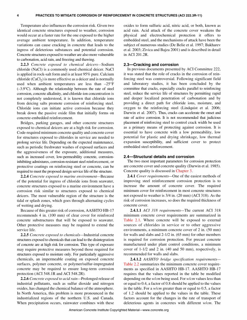
Temperature also influences the corrosion risk. Given twoidentical concrete structures exposed to weather, corrosionwould occur at a faster rate for the one exposed to the higheraverage ambient temperature. In addition, temperaturevariations can cause cracking in concrete that leads to theingress of deleterious substances and potential corrosion.Concrete structures exposed to weather are also more vulnerableto carbonation, acid rain, and freezing and thawing.
2.2.3 Concrete exposed to chemical deicers—Sodiumchloride (NaCl) is a commonly used chemical deicer. NaClis applied in rock-salt form and is at least 95% pure. Calciumchloride (CaCl2) is more effective as a deicer and is normallyused when ambient temperatures are less than –25°F(–3.9°C). Although the relationship between the rate of steelcorrosion, concrete alkalinity, and chloride-ion concentration isnot completely understood, it is known that chloride ionsfrom deicing salts promote corrosion of reinforcing steel.Chloride ions can initiate active corrosion because theybreak down the passive oxide film that initially forms onconcrete-embedded reinforcement.
Bridges, parking garages, and other concrete structuresexposed to chemical deicers are at a high risk for corrosion.Code-required minimum concrete quality and concrete coverfor structures exposed to chlorides in service are needed toprolong service life. Depending on the expected maintenance,such as periodic freshwater washes of exposed surfaces andthe aggressiveness of the exposure, additional measures,such as increased cover, low-permeability concrete, corrosion-inhibiting admixtures, corrosion-resistant steel reinforcement, orprotective coatings on reinforcing steel or concrete, can berequired to meet the proposed design service life of the structure.
2.2.4 Concrete exposed to marine environment—Becauseof the potential for ingress of chloride ions from seawater,concrete structures exposed to a marine environment have acorrosion risk similar to structures exposed to chemicaldeicers. The most vulnerable region of the structure is thetidal or splash zones, which goes through alternating cyclesof wetting and drying.
Because of this greater risk of corrosion, AASHTO HB-17recommends 4 in. (100 mm) of clear cover for reinforcedconcrete substructures that will be exposed to seawater.Other protective measures may be required to extend theservice life.
2.2.5 Concrete exposed to chemicals—Industrial concretestructures exposed to chemicals that can lead to the disintegrationof concrete are at high risk for corrosion. This type of exposuremay require protective measures beyond those required forstructures exposed to moisture only. For particularly aggressivechemicals, an impermeable coating on exposed concretesurfaces, polymer concrete, or polymer/sulfur-impregnatedconcrete may be required to ensure long-term corrosionprotection (ACI 548.1R and ACI 548.2R).
2.2.6 Concrete exposed to acid rain—Prolonged release ofindustrial pollutants, such as sulfur dioxide and nitrogenoxides, has changed the chemical balance of the atmosphere.In North America, this problem is more pronounced in theindustrialized regions of the northern U.S. and Canada.When precipitation occurs, rainwater combines with these
American Concrete Institute Copyri
oxides to form sulfuric acid, nitric acid, or both, known asacid rain. Acid attack of the concrete cover weakens thephysical and electrochemical protection it offers toembedded steel, and the mechanisms of attack have been thesubject of numerous studies (De Belie et al. 1997; Bakharevet al. 2003; Zivica and Bajza 2001) and is described in detailin ACI 201.2R.
2.3—Cracking and corrosionIn previous documents presented by ACI Committee 222,
it was stated that the role of cracks in the corrosion of rein-forcing steel was controversial. Following significant fieldand laboratory studies, it has been concluded by thecommittee that cracks, especially cracks parallel to reinforcingsteel, reduce the service life of structures by permitting rapidand deeper localized penetration of carbonation and byproviding a direct path for chloride ions, moisture, andoxygen to the reinforcing steel (Lindquist et al. 2006;Darwin et al. 2007). Thus, cracks can accelerate the onset andrate of active corrosion. It is not recommended that judiciousplacement of reinforcing steel to control crack width be usedas a primary means of protecting against corrosion. It isessential to have concrete with a low permeability, lowpotential for plastic and drying shrinkage, low thermalexpansion susceptibility, and sufficient cover to protectembedded steel reinforcement.
2.4—Structural details and corrosionThe two most important parameters for corrosion protection
are concrete cover and concrete quality (Darwin et al. 1985).Concrete quality is discussed in Chapter 3.
2.4.1 Cover requirements—One of the easiest methods ofimproving steel reinforcement corrosion protection is toincrease the amount of concrete cover. The requiredminimum cover for reinforcement in most concrete structuresnot exposed to weather is 3/4 in. (20 mm) (ACI 318). As therisk of corrosion increases, so does the required thickness ofconcrete cover.
2.4.1.1 ACI 318 requirements—The current ACI 318minimum concrete cover requirements are summarized inTable 2.1. Where concrete will be exposed to external
sources of chlorides in service or to other aggressiveenvironments, a minimum concrete cover of 2 in. (50 mm)for walls and slabs and 2-1/2 in. (65 mm) for other membersis required for corrosion protection. For precast concretemanufactured under plant control conditions, a minimumcover of 1-1/2 and 2 in. (40 and 50 mm), respectively, isrecommended for walls and slabs.2.4.1.2 AASHTO bridge specification requirements—Table 2.2 summarizes the minimum concrete cover require-
ments as specified in AASHTO HB-17. AASHTO HB-17requires that the values reported in the table be modifieddepending on the w/cm being used. For w/cm values less thanor equal to 0.4, a factor of 0.8 should be applied to the valuesin the table. For a w/cm greater than or equal to 0.5, a factorof 1.2 should be applied to the values in the table. Thesefactors account for the changes in the rate of transport ofdeleterious agents in concretes with different w/cm. Theghted Material—www.concrete.org

PRACTICES TO MITIGATE CORROSION OF REINFORCEMENT IN CONCRETE STRUCTURES (ACI 222.3R-11) 5
Table 2.1—ACI 318-required minimum concrete cover for protection of reinforcementCast-in-place Precast concrete,† in. (mm)
(manufactured underplant-controlled conditions)Nonprestressed,* in. (mm) Prestressed,† in. (mm)
Concrete cast againstand permanently exposedto earth
3 (75) 3 (75) —
Concrete exposedto earth or weather
No. 6 to No. 18 bars: 2(No. 19 to No. 57 bars: 50)No. 5 bar or smaller: 1-1/2
(No. 16 bar, MW200 or MD200 wire, and smaller: 40)
Walls, panels, slabs, joists: 1 (25)Other members: 1-1/2 (40)
Wall panels:No. 14 and No. 18 bars: 1-1/2(No. 43 and No. 57 bars: 40)No. 11 bar and smaller: 3/4(No. 36 bar and smaller: 20)
Other members:No. 14 and No. 18 bars: 2
(No. 43 and No. 57 bars: 50)No. 6 to No. 11 bars: 1-1/2(No. 19 to No. 36 bars: 40)No. 5 bar and smaller: 1-1/4
(No. 16 bar, MW200 and MD200 wire,and smaller: 30)
Concrete not exposedto weather or in contactwith ground
Slabs, walls, joists:No. 14 and No. 18 bars: 1-1/2(No. 43 and No. 57 bars: 40)
No. 11 bar or smaller: 3/4(No. 36 bar or smaller: 20)
Slabs, walls, joists: 3/4 (20)
Slabs, walls, joists:No. 14 and No. 18 bars: 1-1/4(No. 43 and No. 57 bars: 30)No. 11 bar and smaller: 5/8(No. 36 bar and smaller: 15)
Beams, columns:Primary reinforcement, ties,stirrups, spirals: 1-1/2 (40)
Beams, columns:Primary reinforcement: 1-1/2 (40)
Ties, stirrups, spirals: 1 (25)
Beams, columns:Primary reinforcement: db
‡ but not less than 5/8 (15) and need not exceed 1-1/2 (40)
Ties, stirrups, spirals: 3/8 (10)
Shells, folded plate members:No. 6 bar and larger: 3/4
(No. 19 bar and larger: 20)No. 5 bar and smaller: 1/2
(No. 16 bar, MW200 or MD200 wire, and smaller: 13)
Shells, folded plate members:No. 5 bar and smaller: 3/8
(No. 16 bar, MW200 or MD200 wire, and smaller: 10)
Other reinforcement: db‡ but not
less than 3/4 (20)
Shells, folded plate members:No. 6 bar and larger: 5/8
(No. 19 bar and larger: 15)No. 5 bar and smaller: 3/8
(No. 16 bar, MW200 or MD200 wire,and smaller: 10)
*Shall not be less than that required for corrosive environments or for fire protection.†For prestressed and nonprestressed reinforcement, ducts, and end fittings, but not less than that required for corrosive environments or for fire protection.‡db = nominal diameter of bar, wire, or prestressing strand, in. (mm).
American Concrete Institute Copy
Table 2.2—AASHTO-required minimum concrete cover for protection of reinforcement
Situation Cover (in./mm)
Direct exposure to salt water 4.0/100
Cast against earth 3.0/75
Coastal 3.0/75
Exposure to deicing salts 2.5/65
Deck surfaces subject to tire stud or chain wear 2.5/65
Exterior other than above 2.0/50
Interior other than above—Up to No. 11 (No. 36) bar—No. 14 (No. 43) and No. 18 (No. 57)
1.5/402.0/50
Precast soffit form panels 0.8/20
Precast reinforced piles—Noncorrosive environments—Corrosive environments
2.0/503.0/75
Precast prestressed piles 2.0/50
Cast-in-place piles—Noncorrosive environments—Corrosive environments
—General—Protected
—Shells—Auger-cast, tremie concrete, or slurry construction
2.0/503.0/753.0/753.0/752.0/503.0/75
minimum cover should be in accordance with the providedtable, but in no case should it be less than 1.0 in. (25 mm).Also, AASHTO allows that cover over stirrups or ties to be0.5 in. (12 mm) less than the values reported in Table 2.2, butnever less than 1.0 in. (25 mm). Unlike ACI 318, AASHTOHB-17 allows for reduced cover for epoxy-coated reinforcement.The standard allows for interior exposure cover requirementswhen the reinforcement is coated with epoxy.
2.4.2 Drainage—The long-term performance of concretestructures, particularly parking structures and bridges, isenhanced by adequate drainage. Unfortunately, this is one ofthe most overlooked design details. Adequate drainagereduces the risk of corrosion by reducing ponding and thequantity of water and deicing salts that can otherwisepenetrate the concrete.
For both bridges and parking structures, the slope requiredfor drainage is a function of both short-term and long-termdeflections, camber, surface roughness, and the number andlocation of drains. Depending on the layout of the structuralframing system, drainage can be provided by transverse orlongitudinal slopes or both. No simple formula incorporatesall the factors that influence slope and drainage. As a rule ofthumb, the minimum slope should be 1.5%, with 2% beingpreferred (ACI 362.1R). Consideration of time-dependentdeflections is a critical component of a good drainage system
design. Time-dependent deflections are particularlyimportant for prestressed concrete structures.
Drains should be placed to prevent the discharge ofdrainage water against any portion of the structure or onto
righted Material—www.concrete.org

6 PRACTICES TO MITIGATE CORROSION OF REINFORCEMENT IN CONCRETE STRUCTURES (ACI 222.3R-11)
moving traffic below and to prevent erosion at the outlet ofdownspouts. For safety reasons, drains in snow-belt areasshould also be located to prevent melted snow from runningonto a slab and refreezing. Drains, downspouts, and otherdrainage components should be made of a rigid, corrosion-resistant material and be easy to unclog. Additional informationon drainage in parking structures can be found in ACI 362.1R.
2.4.3 Reinforcement—Differences between various typesof steel reinforcement—for example, prestressing,nonprestressing, different grades, manufacturers, andsizes—may be significant factors in the electrochemicalcorrosion of steel. The level of stress in the steel is not asignificant factor in electrochemical corrosion, but can be afactor in certain circumstances related to stress-corrosioncracking of prestressing steel.
For any concrete structure, independent of the risk ofcorrosion, steel reinforcement should be free of loose rustbefore casting the concrete. Measures should be made toprotect steel from exposure to chlorides and other contaminants.Additionally, prestressing steel should be protected from theweather. It is not uncommon for the steel reinforcement in anentire project to be delivered to the site and exposed toweather for months before use. This should be avoided.
Lubricants used to draw prestressing steel appear to raisethe chloride-corrosion threshold (Pfeifer et al. 1987). Theseoils, however, can also adversely affect bond.
Engineering specifications for a project should clearlystate quality-control procedures to ensure that the reinforcement isadequately tied and secured to maintain the minimumspecified concrete cover.
ASTM A767/A767M requires galvanized reinforcingsteel to be treated with a hexavalent chromate to prevent theevolution of hydrogen in fresh concrete. This can occur when anunpassivated zinc surface reacts with hydroxides in freshconcrete (Boyd and Tripler 1968). Hydrogen evolution canalso be prevented by adding a small amount of chromate saltto the fresh concrete (Rosenberg and Gaidis 1978). Calciumnitrite has been used to prevent hydrogen evolution ofgalvanized precast concrete forms (ACI 222R). Additionally,procedures should be provided to minimize electricalconnection with nongalvanized metals. The use of chromatemay be regulated due to health concerns. Research byTan and Hansson (2008) has found that the chromatetreatment may not be necessary.
When epoxy-coated reinforcement is used, ACI 222Rrecommends that there should be no reduction in cover.Because macrocells can develop where defects occur in thecoating, project specifications should clearly state qualitycontrol of the coating and provide procedures to minimize oravoid electrical contact with uncoated metals.
Structures that use unbonded post-tensioned constructionrequire protective measures, especially in aggressivechloride environments.
Because the prestressing elements may not be directlyprotected by an alkaline environment, but instead by acombination of either duct and grout or sheathing and grease,project specifications should clearly indicate that protectionbe maintained for the full length of the tendon and that the
American Concrete Institute Copyrig
duct or sheathing material should be impermeable to water.For unbonded tendons in aggressive environments, theproject specifications should require that sleeves used toconnect the sheathing to the anchorage of encapsulatedsystems should have a positive mechanical connection to theanchorage at all stressing, intermediate, and fixed ends.
ACI 423.7 and ACI 301 provide guidance for additionalmeasures such as corrosion-resistant grease and anchorageprotection. Corrosion-related failure of unbonded prestressingtendons in building and parking structures has occurred in theabsence of chlorides (Schupack 1982; Schupack and Suarez1982). Unbonded monostrand installed before 1985 often hadinadequate sheaths and grease protection. When the provisionsof Post-Tensioning Institute (PTI) “Specifications forUnbonded Single Strand Tendons” (1985) are rigorouslyfollowed, corrosion rarely occurs.
Grouted tendons have had corrosion incidents caused bypoor grouting materials, techniques, and anchorage protection(Schupack 2004). The PTI grouting specification (1985) andACI 423.9M provide more stringent requirements relating togrouting materials, techniques, and anchorage protection.
2.4.4 Joints—Joints should be constructed and sealed toprevent leakage. ACI 224.3R provides guidance on design anddetailing of joints in concrete structures. Additional informationon the design of joints for parking structures can be foundin ACI 362.1R. A discussion on various coatings for water-proofing concrete can be found in ACI 515.1R.
2.4.5 Overlays—For concrete structures with a high risk ofcorrosion, particularly due to external chloride, low-permeability overlays have been used as an alternativeprotection method. The overlay provides additional concretecover to protect embedded reinforcement. In some cases,however, such as bridge decks, the use of overlays has beenshown to increase cracking (Darwin et al. 2004), with acommensurate increase in chloride content at the level of thereinforcing steel (Darwin et al. 2006).
Overlays intended to reduce chloride ingress have beenmade with concrete with a low w/cm, latex-modifiedconcrete, polymer concrete, and concrete with pozzolan(ACI 224R). Designs should include the compatibility of theoverlay and the substrate concrete in terms of mechanicalproperties and should consider potential shrinkage crackingcaused by restrained volume changes.
2.4.6 Embedded items—In general, any embedded metal inconcrete should have the same minimum concrete cover as thatrecommended for steel reinforcement for the anticipatedexposure conditions. If this cannot be achieved, then additionalprotective measures are needed. Embedded items require addi-tional protection when exposed to an aggressive environment.
Precast parking structures often contain weld plates usedto connect components. In aggressive environments,consideration should be given to the use of galvanized orstainless steel for these plates or painting the plates withepoxy after field welding. If the connection plates aregalvanized, consideration should be given to the possibilityof developing galvanic cells if connections are made tonongalvanized steel. Similar galvanic cells can be createdbetween architectural features, such as handrails, and the
hted Material—www.concrete.org

PRACTICES TO MITIGATE CORROSION OF REINFORCEMENT IN CONCRETE STRUCTURES (ACI 222.3R-11) 7
CHAPTER 3—IMPACT OF MIXTURE PROPORTIONING, CONCRETING MATERIALS,
AND TYPE OF EMBEDDED METAL
reinforcement. Such architectural features should be galvanizedor otherwise protected such that galvanic cells are not formed.
In submerged concrete structures with unbedded, freelyexposed steel components in contact with reinforcing steel,galvanic cells can develop with the freely exposed steel formingthe anode and the embedded steel forming the cathode. This cancause corrosion of the embedded, freely exposed steel. If exposedconnections are necessary, then corrosion protection, such as theuse of an epoxy coating, is necessary.
3.1—Influence of mixture proportioning on corrosion of reinforcing steel
3.1.1 Introduction—The proportioning of concretemixtures that enhance the corrosion resistance of reinforcingsteel is not substantially different from the proportioning ofmixtures for any high-quality concrete. The goal is to useavailable materials to develop a concrete mixture that willpermit mixing, transporting, placing, consolidating, andfinishing in the fresh state and, when cured properly, willhave a low permeability in the hardened state. Mixtureproportions should permit pumping of the concrete, ifrequired, and control bleeding and minimize shrinkage.
ACI 201.2R describes in detail the general durability ofconcrete, determined largely by the selection of cement,aggregates, water, and admixtures. When considering theeffects of reduced permeability, freezing-and-thawingresistance, alkali-aggregate reaction, and sulfate attack onthe corrosion of reinforcing steel, the most important concreteproperty is reduced permeability. Permeability describes the rateof movement of liquids or gases through concrete and is related tothe connectivity of pores and voids in the hardened concrete.Assuming there is adequate curing, permeability can be reducedprimarily through the use of chemical admixtures to achieve thelowest practical w/cm, and secondly through the use of pozzolanicadmixtures, supplementary cementitious materials, and polymers(ACI 212.3R, ACI 212.4R, ACI 232.1R, ACI 232.2R, ACI 233R,ACI 234R, and ACI 548.1R).
3.1.2 Benefits of low w/cm—The benefits of reducing thew/cm to delay the corrosion of reinforcing steel are demonstratedin ACI 222R, which shows that the reduction in the flow ofoxygen through concrete is a function of the reduction in w/cm.The report also shows the effects of w/cm on reducing saltpenetration and increasing time-to-corrosion. In each ofthese cases, the benefit of reducing the w/cm can be interpretedas a result of the reduction in the permeability of the concrete.
For these reasons, w/cm is limited to certain maximumvalues for concrete that will be exposed to a corrosiveenvironment. ACI 201.2R and ACI 211.1 containrecommended values for w/cm, and Chapter 4 of ACI 318gives maximum values for the w/cm. All three documentsrecommend that w/cm should not exceed 0.40 for concreteexposed to chlorides from seawater, deicing salts, and othersources. AASHTO HB-17 limits the w/c to 0.49 forClass P > 4000 psi (> 28 MPa) concrete.
In cases where the shrinkage of concrete is restrained, suchas bridge decks, the use of a lower w/cm can have negative
American Concrete Institute Copyr
effects in the form of increased cracking (Krauss and Rogalla1996; Darwin et al. 2004). The increased cracking is caused bya decrease in tensile creep that results from the increase inconcrete strength obtained with the lower w/cm. High-strengthconcrete exhibits less creep, even at the same stress-strengthratio, than normal-strength concrete (Smadi et al. 1987).
3.1.3 Proportioning mixtures for low w/cm—Reducing thequantity of mixing water relative to the mass of cementitiousmaterials decreases the w/cm. Simply removing water froma given mixture, however, will generally result in a lessworkable mixture. To preserve workability, which is typicallycharacterized by slump, and reduce w/cm, it is necessaryto maintain the water content while increasing thecementitious materials content. By doing this, thecontractor’s placement needs can be met, while at thesame time providing the dense, low-permeability concreterequired. This means that a low-w/cm mixture will haveincreased cement content and an accompanying increase incost. For concrete with a low slump or low water demand, thisapproach is satisfactory for moderate reductions in the w/cm.
For mixtures requiring a greater slump for placement orfinishing purposes, or for the establishment of a w/cm of 0.40or less, an increase in cement content alone will lead toexcessive cement factors, which can lead to concretemixtures with high mortar contents and an increasedtendency toward plastic and drying-shrinkage cracking. Inaddition, the heat of hydration developed with higher cementcontents results in higher early-age temperatures, which canlead to thermal cracking if proper actions are not taken tominimize high thermal gradients in the concrete element. Toreduce the water content at a given cement content, water-reducing admixtures, which effectively reduce the watercontent required to obtain a desired slump, are used. Thereduced water content may then lead to reduced cementcontent for the same w/cm. For greater reductions in water,high-range water-reducing admixtures (HRWRAs) (ASTMC494/C494M Types F and G) are used.
The effects of aggregate size and gradation on the watercontent required for a particular level of workability should notbe overlooked. Smaller aggregate sizes demand more water asdo intentionally or unintentionally gap-graded aggregates. Byusing the largest aggregate size commensurate with thestructural details of the members being placed andcontrolling gradations, it is possible to reduce the water andcement contents required for a particular w/cm. It can be moreeconomical to design a low-w/cm, low-permeability mixturebased on 1-1/2 in. (37.5 mm) coarse aggregates than with 3/8 in.(9.5 mm) coarse aggregates. Further, appropriate selection andgradation of aggregates permit pumping, placement, andfinishing of concrete at a lower slump than required whenless-than-optimum aggregate sizes and gradations are used.
3.2—Influence of selection of cement, aggregates, water, and admixtures on corrosion of reinforcing steel
3.2.1 Selection of cement—The influence of portlandcement’s chemistry on the corrosion of reinforcing steel isdiscussed in detail in ACI 201.2R, 222R, 225R, and Whiting
ighted Material—www.concrete.org

8 PRACTICES TO MITIGATE CORROSION OF REINFORCEMENT IN CONCRETE STRUCTURES (ACI 222.3R-11)
(1978). The characteristic alkaline nature of hardenedcement paste normally maintains the corrosion resistance ofsteel in concrete; this protection is lost when chloride ionscontaminate concrete or when carbonation occurs.
One of the mineral constituents of portland cement, C3A,(tricalcium aluminate) has the ability to react with chlorideions to form chloroaluminates, thereby reducing the impactof chloride contamination on corrosion. C3A can represent 4to 12% of the mass of cement. ASTM C150/C150M cementtypes (Types I through V) contain varying amounts of C3A,but the effect of this constituent is not sufficiently clear towarrant selecting a chloride-reducing cement on the basis ofC3A content. Further, other durability problems, such assulfate attack, become more likely as the C3A content isincreased. There is work, however, that shows corrosioninitiates early in Type V cements in the presence of chlorideand in chloride environments (Masledhuddin et al. 2007;Page et al. 1981) Also, in the presence of chloride, there is noincrease in the susceptibility to sulfate attack with higherC3A content (Rasheeduzzafar et al. 1990; Sakr 2005).
Higher-alkali cements are effective in providing a higherpH environment around the steel and reducing the corrosionpotential of steel in the presence of chloride ions. Similarly,the use of a cement with a higher alkali content increases therisk of alkali-aggregate reaction. Unless the producer iscertain that the aggregate selected for the concrete mixture isnon-alkali reactive, the use of high-alkali cement to enhancecorrosion resistance is not recommended.
Any portland cement meeting the requirements ofASTM C150/C150M can be used to produce a high-qualityconcrete that will reduce or prevent the corrosion ofembedded reinforcing steel. Factors such as the selection andmaintenance of a low w/cm and proper placement, consolidation,finishing, and curing practices are more important than theselection of cement in regard to corrosion.
Blended cements, in which the portland-cement clinker isinterground with a supplementary cementitious material,will result in reduced permeability in suitably designedconcrete. Uniform dispersion of the blended cement isneeded but is harder to maintain as the difference in particle-size distribution between the cement and the blendedsupplementary cementitious material increases. When properlydispersed, silica fume or other supplementary cementitiousmaterials can significantly reduce chloride ingress.
3.2.2 Selection of aggregates—ACI 201.2R and 222R discussaggregate selection for durable concrete. Issues such as soundness,freezing-and-thawing resistance, wear resistance, andalkali reactivity should be addressed in addition to otheraggregate characteristics that relate to the corrosion protectionfor the steel.
Two primary issues govern the selection of aggregates foruse in concrete exposed to a corrosive environment:
1. The use of aggregates that introduce chloride ions into themixture, which is discussed in detail in ACI 201.2R and 222R; and
2. The development of corrosion-resistant concrete is theproper selection of aggregate size and gradation to enhancethe workability of the mixture and reduce the required watercontent (Section 3.1).
American Concrete Institute Copyrig
The chloride-ion concentration limits discussed in thisguide can be exceeded through the use of aggregates thatcontain absorbed chloride ions. Judicious materials selectionrequires that the chloride-ion content of the proposedaggregates be evaluated before use. Free chlorides on thesurface or readily available from pore spaces in the aggregatecan be determined by relatively simple analytical means(Gaynor 1986). Tightly bound chlorides, however, will notlikely contribute significantly to corrosion. It has beenshown, however, that the bound chlorides can be releasedand contribute to the corrosion (Glass and Buenfeld 2000).Determination of the amount of bound chlorides that canenter into the pore solution requires specialized testingprocedures (Hope et al. 1985; ACI 222R).
Once an aggregate source has been selected, attentionshould be given to monitoring the moisture content of boththe coarse and fine aggregates at the time of inclusion in themixture. Errors in assessing the moisture content can lead tosubstantial increases in the w/cm of the mixture, resulting indramatic increases in permeability.
3.2.3 Selection of mixture water—Seawater should neverbe used to make concrete for reinforced structures. Waterwith chloride contents exceeding values given in ASTMC1602/C1602M should not be used to make concrete forreinforced structures because it may contribute enoughchloride ions to cause serious corrosion problems.
3.2.4 Selection of chemical and supplementary cementitiousadmixtures—A wide variety of chemical and supplementarycementitious admixtures is available that either directlyimproves the corrosion protection provided by the hardenedconcrete or modifies the properties of the fresh concrete,permitting the use of lower w/cm mixtures with theiraccompanying benefits in enhancing corrosion protection. Certainadmixtures, however, can increase the chloride-ion content,lowering corrosion protection. It may be necessary to determinethe chloride-ion contribution of the admixture before use.Additionally, it is wise to check the compatibility betweencement, admixtures, and other concrete ingredients bymaking field trial batches before starting construction.Incompatibility of materials can lead to rapid slump loss,rapid set, and increased water demand, which can adverselyaffect the corrosion resistance of the concrete.
3.2.4.1 Chemical admixtures—These materials are generallyadded in liquid form either during batching or upon arrival atthe job site. The quantities used are quite small relative to themass or volume of other materials in the concrete mixture,and careful control of the dosage is required. For example, itwould not be unusual to add less than 18 fl oz. (530 mL) ofadmixture to 4000 lb (1820 kg) of fresh concrete. ACI 212.3Rcontains specific guidance relating to the use of admixtures.Admixtures can be grouped into the following classifications:• Air-entraining admixtures—The use of air-entraining
admixtures to develop a proper air-void system inconcrete is necessary in a freezing-and-thawingenvironment. In many concrete mixtures, air entrainmentalso permits a reduction in water content because the airbubbles increase the workability of the mixture. If thecement content of the mixture is held constant while the
hted Material—www.concrete.org

PRACTICES TO MITIGATE CORROSION OF REINFORCEMENT IN CONCRETE STRUCTURES (ACI 222.3R-11) 9
water content is reduced, the net result is a decrease in thew/cm and permeability (Kosmatka et al. 2003). Air-entraining admixtures, therefore, have an indirect benefiton enhancing corrosion protection. In many cases,environmental conditions require both freezing-and-thawing resistance and corrosion protection. Air-entrainingadmixtures should be specified using ASTM C260/C260M.
• Water-reducing admixtures—These chemicals areformulated to increase the workability or fluidity offresh concrete by breaking up and dispersing agglomerationsof fine cement particles. High-range water reducers canincrease the workability of a concrete mixture proportionedfor a given water content. Alternatively, these admixturespermit a reduction in the quantity of water required toachieve a particular slump. When this water reductionis matched with a reduction in cement, the w/cmremains the same. If the cement factor is kept constantwhile the water content is reduced, workability ismaintained with a reduction in w/cm and a reduction inpermeability. Water-reducing admixtures are classifiedas Types A, D, or E in ASTM C494/C494M, dependingon their effects on time-of-setting.
• High-range water-reducing admixtures—HRWRAsprovide dramatic increases in workability at the same w/cmor at a reduced water content at the same slump. Through theuse of HRWRAs, concrete with low w/cm and markedreductions in permeability can be produced whilemaintaining workability. ACI 318 and ACI 357Rrecommend a w/cm less than or equal to 0.40 for concretethat will be exposed to deicing salts or a marineenvironment. HRWRAs can be used to achieve low w/cmand are classified as Types F and G in ASTM C494/C494M,where the latter indicates a retarding effect.
• Accelerating admixtures—Accelerators reduceconcrete setting times and improve early strength. Theyare typically used to compensate for slower cementhydration when temperatures are below 60°F (16°C).One of the most common accelerators is calcium chloride.For steel-reinforced or prestressed concrete structures,however, admixed chlorides can lead to severe corrosion,especially if the concrete is subjected to wetting andchloride ingress. Admixtures that contain intentionallyadded chloride or other halides should not be used. Anonchloride accelerator should be noncorrosive within itsrecommended dosage range. Accelerating admixtures areclassified as Type C or E in ASTM C494/C494M.
• Retarding admixtures—When temperatures areabove 80°F (27°C), set retarders increase the settingtime, thereby extending the time during which theconcrete can be transported, placed, and consolidatedwithout the need for additional water. Thus, the desiredw/cm and, consequently, the intended permeabilityand durability characteristics of the concrete, aremaintained. Set-retarding admixtures are classified asTypes B or D in ASTM C494/C494M.
• Corrosion-inhibiting admixtures—Corrosion-inhibitingadmixtures delay the onset of corrosion and reduce the rateof corrosion of reinforcement due to chloride attack.
American Concrete Institute Copyrig
3.2.4.2 Chemical admixtures—Two main types ofchemical admixtures extend the time to corrosion-induceddamage of steel-reinforced concrete structures in chloride-laden environments: corrosion inhibitors and physical-barrier admixtures. Some corrosion inhibitors also act asphysical-barrier admixtures.
3.2.4.3 Corrosion inhibitors—ISO 8044 defines corrosioninhibitors as chemical substances that decrease the corrosionrate when present at a suitable concentration, withoutsignificantly changing the concentration of any othercorrosion agent. Recent research, however, indicates that forsome inhibitors, such as calcium nitrite, their role is to delaythe initiation of corrosion (Hansson et al. 1998; Mammolitiet al. 1999). Nonetheless, these admixtures provideprotection to the steel surface, either electrochemically(anodic, cathodic, mixed-inhibitor), chemically (chemicalbarrier), or as a chloride scavenger within the concrete coverto inhibit chloride-induced corrosion initiation. Inorganicchemical compounds that protect steel against chlorideattack in a basic pH concrete environment include borates,chromates, molybdates, nitrites, and phosphates. Calciumnitrite is the most researched inorganic inhibitor and themost widely used. Organic compounds used in admixtures toprotect steel from chloride-induced corrosion includealkanolamines and an aqueous mixture of amines and fatty-acid esters (Berke et al. 1993; Bobrowski and Youn 1993;Mäder 1995; Martin and Miksic 1989; Nmai et al. 1992;Nmai and Krauss 1994).
Organic amine-based compounds, such as some aminesalts and alkanolamine, were reported to be effective corrosioninhibitors for steel in concrete when used in a post-treatmentprocess for chloride-induced corrosion of steel in concrete inlaboratory studies (Al-Qadi et al. 1992; Collins et al. 1993;Dillard et al. 1992). Results of long-term field evaluations oftopically-applied corrosion inhibitors are conflicting (Islamet al. 2002; Sprinkel 2003; Sharp 2004; Schiegg et al. 2000).
Physical-barrier admixtures reduce the rate of ingress ofcorrosive agents (chlorides, oxygen, and water) into theconcrete. Bitumen, silicates, and water-based organicadmixtures consisting of fatty acids such as oleic acid, stearicacid, salts of calcium oleate, and esters such as butyloleate aretypically used in these types of admixtures. A liquid admixturecontaining a silicate copolymer in the form of a complex,inorganic, alkaline earth may also be effective in reducing thepermeability of concrete and providing protection againstcorrosion of reinforcing steel (Miller 1995).
3.2.4.4 Supplementary cementitious admixtures—Thesesolid admixtures reduce the rate of penetration of water andchloride-containing solutions through the formation ofadditional hydration-type products or by plugging capillarypores in the portland-cement paste. The admixtures are effectivein reducing the rate of water transmission through concrete underexternally applied hydraulic pressures. They include:
• Fly ash—Fly ash is widely used as a partial replacementfor cement in concrete. Workability is often improved,especially for low-w/cm mixtures, and permeability tochloride ions is reduced. The use of Type F fly ash will
hted Material—www.concrete.org

10 PRACTICES TO MITIGATE CORROSION OF REINFORCEMENT IN CONCRETE STRUCTURES (ACI 222.3R-11)
also reduce the maximum temperature rise of concrete.Fly ash should be specified using ASTM C618.
• Slag cement—Slag cement is added as a cementsubstitute or blended into cement. It reducestemperature rise in large members and decreasespermeability to chloride ions. Slag cement should bespecified using ASTM C989.
• Natural pozzolans—Natural pozzolans provide someimprovement in permeability reduction but are not aseffective as fly ash or slag cement. Natural pozzolan isalso specified using ASTM C618.
• Silica fume (condensed silica fume)—Silica fume isan effective pozzolan in reducing concrete permeabilityto chloride-ion ingress when used in combination withHRWRAs, and will provide higher strengths when usedas a partial cement substitute or as an addition. Becauseof its high water demand, the use of an HRWRA isneeded to improve dispersion of the silica fume andworkability of the concrete mixture, especially at thelow water contents typically used. Silica fume shouldbe specified using ASTM C1240.3.2.4.5 Polymers—Polymer concrete and polymer-
modified concrete are commonly used in concreteconstruction and repair of concrete structures. In polymerconcrete, the polymer is used as a binder for the aggregate,whereas in polymer-modified concrete, the polymer is usedalong with portland cement. Low permeability and improvedbond strength to concrete substrates and other surfaces aresome of the advantages of polymers. More details on polymersand polymer concrete are given in ACI 548.1R.
3.3—Uncoated reinforcing steelFor most reinforced concrete construction in the U.S., deformed
billet-steel reinforcing bars conforming to ASTM A615/A615Mare used (ACI 318). Reinforcing bars can also meet requirementsof ASTM A706A706M, A996/A996M, A955/A955M andA1035/A1035M specifications. Factors such as level of stresshave not been found to play a major role in corrosion susceptibilityin the concrete environment (ACI 222R).
3.4—Epoxy-coated reinforcing steel3.4.1 Introduction—After several evaluations and a
research study involving numerous types of coatings(Clifton et al. 1974), fusion-bonded epoxy coating emergedduring the 1970s as an acceptable method of corrosionprotection for uncoated reinforcing steel in concrete. Today,fusion-bonded coatings are one of the most widely usedcorrosion protection alternatives in North America, particularlyfor mild-steel reinforcing bars. As of 1998, there wereapproximately 100,000 structures containing epoxy-coatedreinforcement (Virmani and Clemena 1998).
Because fusion-bonded epoxy coatings form barriers,some protection is lost when the coating is damaged. Breaksin the coating reduce the electrical resistance (Clear 1992b;Wiss, Janey, Elsner Associates, Inc. 1992) and permitcontaminants to reach the steel surface. Long-term adhesion of theepoxy coating to the steel substrate is vital to corrosionperformance. Studies have shown that corrosion performance is
American Concrete Institute Copyrig
not impaired by loss of adhesion when there are no breaks in thecoating, but it is reduced substantially in the presence of defects(Surface Science Western 1995; Martin et al. 1995).
Although proper handling and quality-control measureswill reduce damage and other coating defects, it is unrealisticto expect defect-free coated bars in the field. Defects canresult from imperfections in the steel surface, inadequatefilm thickness, improper fabrication, rough handling, andconsolidation of the concrete.
3.4.2 Corrosion-protection performance—The degree ofcorrosion protection provided by epoxy coatings iscontroversial. Numerous laboratory (Clear and Virmani1983; Clifton et al. 1974; Erdogdu and Bemner 1993; Wiss,Janney, Elstner Associates, Inc. 1992; Pfeifer et al. 1993;Scannell and Clear 1990; Sohanghpurwala and Clear 1990;and Virmani et al. 1983) and field studies have shown thatepoxy-coated reinforcing steel has a longer time-to-corrosion than uncoated reinforcing steel. Many fieldstudies undertaken in the 1990s examining the performanceof bridge decks in service for 15 years or more reportedexcellent results (Gillis and Hagen 1994; Hasan et al.1995; Perregaux and Brewster 1992; West Virginia DOT 1994).
There have also been examples of corrosion-induceddamage in structures containing epoxy-coated reinforcement,most notably in the splash zones of the substructure componentsof five large bridges in the Florida Keys. These bridgesbegan to exhibit corrosion spalling within 5 to 7 years ofconstruction (Smith et al. 1993). Isolated examples of corrosionhave also been reported in bridge decks, barrier walls, and aparking garage (Clear 1994). An investigation in Ontario(Manning 1996) showed loss of adhesion in bridges that hadbeen in service for less than 15 years. The degree of adhesionloss of the coating correlated with the age of the structure andwas found in bars embedded in chloride-contaminated andchloride-free concrete. Other studies have reported pooradhesion on bars removed from older structures (Clear 1994).
Extensive laboratory and field studies were undertaken todetermine the cause of corrosion problems with epoxy-coated bars (Sagues and Powers 1990; Sagues et al. 1994;Zayed et al. 1989). Other studies attempting to identify thefactors affecting the performance of coated reinforcementwere funded by the Concrete Reinforcing Steel Institute(CRSI) (Clear 1992b; Wiss, Janey, Elsner Associates, Inc.1992), the Canadian Strategic Highway Research Program(SHRP) (Clear 1992a, 1994) and the National CooperativeHighway Research Program (Clear et al. 1995).
These studies have significantly contributed to under-standing the long-term field performance of epoxy-coatedreinforcement, but they have not related this performance tospecific production variables or to results of short-termlaboratory testing. From investigations on laboratory andoutdoor-exposure specimens containing bars manufacturedaccording to the 1987 specifications, a failure mechanismwas identified involving progressive loss of coatingadhesion accompanied by under-film corrosion on coatedbars (Clear 1994; Clear et al. 1995). This led to theconclusion that epoxy-coated reinforcement can extendthe time-to-corrosion by 3 to 6 years in bridges exposed to
hted Material—www.concrete.org

PRACTICES TO MITIGATE CORROSION OF REINFORCEMENT IN CONCRETE STRUCTURES (ACI 222.3R-11) 11
salt (marine and deicing) compared with uncoated steel inthe same environment. Clear (1994) estimated that the time-to-corrosion damage could be extended to 8 to 11 years if thequality of the coatings were improved.
There is no dispute that epoxy coating will extend thetime-to-corrosion damage compared with uncoated steel, butthe long-term performance remains somewhat uncertain. Notall factors affecting corrosion performance are understood; thereare many examples of good performance and prematurecorrosion damage. The dominant factors affecting performanceare the number and size of defects in the coating. Whereepoxy-coated reinforcement is used, it is essential thatquality-control and assurance measures focus on these twoproperties. A number of specifications, such as ASTMD3963/D3963M, ASTM A775/A775M, and AASHTOM284M/M284 are available. These specifications continueto be updated with the progress of research studies.
Where a coated bar is used in a structure, it is advisable tocoat steel that would otherwise be electrically connected(Scannell and Clear 1990). The onset of corrosion occursindependently of whether the coated bars are coupled touncoated bars. During the propagation phase, however, anuncoated bottom mat electrically coupled to a top mat canfacilitate macrocell action that can increase corrosion rates,compared with electrically isolated bars (Schiessl 1992).
Most bars are coated as straight bars and then fabricated asrequired by bending schedules. Studies have shown that bentbars generally exhibit more damage and do not perform aswell in corrosion studies (Clear 1992b; McDonald et al.1995). As a result, some users are now requiring bendingbefore coating.
3.4.3 Inspection and testing
3.4.3.1 Holiday testing—Holidays are pinholes,discontinuities, or other coating defects not visible to thenaked eye. Abrasions, cuts, and other damage incurred duringhandling, shipping, or placement are not considered holidays.
Most production lines are equipped with in-line holidaydetectors that operate continuously. Hand-held holidaydetectors are often used to spot check in-line results. Holidaytesting is used primarily as a quality-control and inspectiontool in the plant; normally, it is not intended for use inassessing coating damage at the job site.
3.4.3.2 Coating thickness—The thickness of the appliedcoating is also an important performance parameter. Thickercoatings generally have fewer holidays and other discontinuitiesas well as higher dielectric properties. Thicker coatings alsoprovide a better barrier to water and chloride ions, therebyconferring a higher degree of corrosion protection.
Structural considerations such as creep, fatigue, and bonddevelopment of the coated reinforcing steel limit themaximum allowable coating thickness. Most standardspecifications require that 90% of the thickness measurementsbe between 7 to 12 mils (175 to 300 mm). Fatigue and creepperformance of coated reinforcing steel are comparable touncoated reinforcing bar when coating thickness is withinthese limits. ACI 318 requires a 20 to 50% increase in thebasic development lengths for epoxy-coated reinforcing
American Concrete Institute Copyri
steel, depending on the bar spacing and concrete cover, toaccount for the reduced bond associated with the coating.
3.4.3.3 Bend test—The bend test is another quality-controltechnique used to evaluate the application process. Aproduction-coated bar is bent 120 to 180 degrees around amandrel of a specified size. If the coating cracks, debonds, orboth, there is a problem in the application process.
3.4.3.4 Coating adhesion—The bend test has been theprincipal quality-assurance technique used to evaluatecoating adhesion in the plant. Additional means may beneeded, however, to adequately evaluate adhesion on aproduction bar. Three tests were adopted in ASTMA775/A775M to supplement the existing bend test:
1. Hot water;2. Cathodic debonding; and3. Salt-spray.These tests were used in the evaluation of epoxy coatings
for other applications such as pipeline coatings and are morediscriminating than the bend test in identifying relativedifferences in adhesion.
3.4.3.5 Coating repair—Coating defects and damagecaused during production are repaired in the plant. Patchingor touch-up material should conform, as applicable, toASTM A775/A775M or ASTM A934/A934M, as specifiedin ACI 301, and should be applied in strict accordance withthe manufacturer’s recommendations. Generally, surfacepreparation is accomplished with a wire brush, emery cloth,sandpaper, or file. The repair material is typically applied bybrush. The same procedures are followed to coat bar ends.
3.4.4 Field practice3.4.4.1 Fabrication—Reinforcing steel is most often
fabricated or cut and bent to shape after coating becausemost production lines are designed for coating long, straightbars. Any cracks or other damage in the bend areas should beproperly repaired before shipping the bars to the job site.
3.4.4.2 Handling and transportation—Epoxy coatingscan be damaged by improper handling and storage. Epoxy-coated steel should be bundled using plastic-coated wire tiesor other suitable material. Excess sag that can cause bar-to-bar abrasion should be avoided when lifting bundles ofcoated steel. Nylon slings or padded wire ropes should beused to lift bundles in the plant and at the job site. Coatedsteel is usually shipped by rail or trucked to the project.Precautions should be taken to minimize scraping bundlesduring transport. Dragging coated bars over other bars or anyabrasive surface should be avoided.
3.4.4.3 Storage—Epoxy-coated steel should be stored ontimbers or other noncorrosive material. The storage areashould be as close as possible to the area of the structurewhere the steel will be placed to minimize handling. Coatedsteel should not be dropped or dragged. Epoxy-coated steelshould not be stored outdoors for longer than 3 months. Iflong-term outdoor storage cannot be prevented, the steelshould be protected from direct sunlight and sheltered fromthe weather by covering it with opaque polyethylene sheetsor other suitable waterproofing material. Provisions shouldbe made to allow adequate air circulation around the bars tominimize condensation under the covering.
ghted Material—www.concrete.org
12 PRACTICES TO MITIGATE CORROSION OF REINFORCEMENT IN CONCRETE STRUCTURES (ACI 222.3R-11)
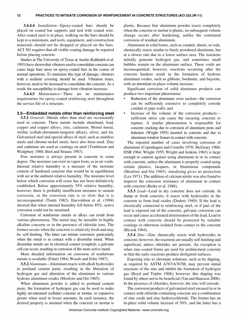
3.4.4.4 Installation—Epoxy-coated bars should beplaced on coated bar supports and tied with coated wire.After coated steel is in place, walking on the bars should bekept to a minimum, and tools, equipment, and constructionmaterials should not be dropped or placed on the bars.ACI 301 requires that all visible coating damage be repairedbefore placing concrete.
Studies at The University of Texas at Austin (Kahhaleh et al.1993) have shown that vibrators used to consolidate concrete cancause large bare areas on epoxy-coated bars in the course ofnormal operations. To minimize this type of damage, vibratorswith a resilient covering should be used. Vibration times,however, need to be increased to consolidate the concrete. As aresult, the susceptibility to damage from vibration increases.
3.4.4.5 Maintenance—There are no maintenancerequirements for epoxy-coated reinforcing steel throughoutthe service life of a structure.
3.5—Embedded metals other than reinforcing steel3.5.1 General—Metals other than steel are occasionally
used in concrete. These metals include aluminum, lead,copper and copper alloys, zinc, cadmium, Monel metal,stellite (cobalt-chromium-tungsten alloys), silver, and tin.Galvanized steel and special alloys of steel, such as stainlesssteels and chrome-nickel steels, have also been used. Zincand cadmium are used as coatings on steel (Tomlinson andWedgbury 1988; Bird and Strauss 1967).
Free moisture is always present in concrete to somedegree. The moisture can exist in vapor form, as in air voids.Internal relative humidity is a measure of the moisturecontent of hardened concrete that would be in equilibriumwith air at the ambient relative humidity. The moisture levelbelow which corrosion will cease has not been definitivelyestablished. Below approximately 55% relative humidity,however, there is probably insufficient moisture to sustaincorrosion, or the corrosion rate is so slow that it isinconsequential (Tuutti 1982). Enevoldsen et al. (1994)showed that when internal humidity fell below 85%, activecorrosion could not be sustained.
Corrosion of nonferrous metals or alloys can result fromvarious phenomena. The metal may be unstable in highlyalkaline concrete or in the presence of chloride ions. Theformer occurs when the concrete is relatively fresh and maybe self-limiting. The latter can initiate corrosion, particularlywhen the metal is in contact with a dissimilar metal. Whendissimilar metals are in electrical contact (coupled), a galvaniccell can occur, resulting in corrosion of the more active metal.
More detailed information on corrosion of nonferrousmetals is available (Fintel 1984; Woods and Erlin 1987).
3.5.2 Aluminum—Aluminum reacts with alkali hydroxidesin portland cement paste, resulting in the liberation ofhydrogen gas and alteration of the aluminum to varioushydrous aluminum oxides (Monfore and Ost 1965).
When aluminum powder is added to portland cementpaste, the formation of hydrogen gas can be used to makehighly air-entrained (cellular) concrete or mortar, or expansivegrouts when used in lesser amounts. In each instance, thedesired property is attained when the concrete or mortar is
American Concrete Institute Copyrig
plastic. Because fine aluminum powder reacts completelywhen the concrete or mortar is plastic, no subsequent volumechange occurs after hardening, unlike the continuedcorrosion of residual aluminum.
Aluminum in solid forms, such as conduit, sheets, or rods,chemically reacts similar to finely powdered aluminum, butat a slower rate due to a lower surface area. The reactionsinitially generate hydrogen gas, and sometimes smallbubbles remain on the aluminum surface. These voids areinconsequential; however, reactions occurring after theconcrete hardens result in the formation of hydrousaluminum oxides, such as gibbsite, boehmite, and bayerite,with an attendant in-place volume increase.
Significant corrosion of solid aluminum products canproduce two important phenomena:• Reduction of the aluminum cross section—the corrosion
can be sufficiently extensive to completely corrodeconduit or pipe walls; and
• Increase of the volume of the corrosion products—sufficient stress can cause the encasing concrete torupture. A similar phenomenon is responsible forconcrete cracking due to corrosion of aluminum posts andbalusters (Wright 1955) inserted in concrete and due toaluminum window frames in contact with concrete.
The reported number of cases involving corrosion ofaluminum (Copenhagen and Costello 1970; McGeary 1966;ENR 1964; Wright 1955; Wright and Jenkins 1963) is largeenough to caution against using aluminum in or in contactwith concrete, unless the aluminum is properly coated usingcertain plastics, lacquers, or bituminous compounds(Monfore and Ost 1965). Anodizing gives no protection(Lea 1971). The addition of calcium nitrite was also found toimprove the corrosion resistance of aluminum in contactwith concrete (Berke et al. 1988).
3.5.3 Lead—Lead in dry concrete does not corrode. Indamp or fresh concrete, it reacts with hydroxides in theconcrete to form lead oxides (Dodero 1949). If the lead iselectrically connected to reinforcing steel, or if part of thelead is exposed out of the concrete, galvanic corrosion canoccur and cause accelerated deterioration of the lead. Lead incontact with concrete should be protected by suitablecoatings or otherwise isolated from contact to the concrete(Biczok 1964).
3.5.4 Zinc—Zinc chemically reacts with hydroxides inconcrete; however, the reactions are usually self-limiting andsuperficial, unless chlorides are present. An exception iswhen zinc-coated forms are used for architectural concreteso that the early reactions produce disfigured surfaces.
Exposing zinc to chromate solutions, such as by dipping,as required by ASTM A767/A767M, may prevent initialreactions of the zinc and inhibit the formation of hydrogengas (Boyd and Tripler 1968); however, this dipping wasfound by others not to be beneficial (Tan and Hansson 2008).In the presence of chlorides, however, the zinc will corrode.
The corrosion products of galvanized steel encased in or incontact with chloride-containing concrete are a combinationof zinc oxide and zinc hydroxychloride. The former has anin-place solid volume increase of 50%, and the latter has a
hted Material—www.concrete.org

PRACTICES TO MITIGATE CORROSION OF REINFORCEMENT IN CONCRETE STRUCTURES (ACI 222.3R-11) 13
CHAPTER 4—CONSTRUCTION PRACTICES
solid volume increase of 300% (Hime and Machin 1993).Under certain circumstances, the volume increase due to thelatter can develop sufficient stress to crack the surroundingconcrete. The corrosion of the zinc layer subsequentlyexposes the underlying steel to the chloride environment,and corrosion of the steel will ensue.
Zinc-alloy beams used as joists in certain constructions,galvanized reinforcing steel bars, galvanized corrugatedsteel used for permanent forms, and galvanized steel ties inmasonry, have deteriorated extensively when chlorides arepresent. The zinc coating corrodes initially, followed by the steel.
Field studies on the performance of galvanized steel inreinforced concrete structures exposed to chlorides inservice have yielded conflicting results (Arnold 1976; Cook1980). In general, galvanizing is an inappropriate means forproviding long-term protection for steel in concrete ifchlorides are present or will be introduced into the concretefrom the environment (Arnold 1976; Griffin 1969; Mange1957; Stark and Perenchio 1975).
3.5.5 Copper and copper alloys—Copper is chemicallystable in concrete, except when chlorides or ammonia arepresent. Ammonia can cause stress corrosion of the copperand early failure under loads. Ammonia is usually environ-mentally derived and not a normal component of concrete;however, copper pipes embedded in air-entrained concretehave corroded because the air-entraining admixture releasedsmall amounts of ammonia, which enhanced and acceleratedstress corrosion of the copper pipes (Monfore and Ost 1965).A galvanic cell is created when copper is electricallyconnected to reinforcing steel in which the steel becomesanodic and corrodes in the presence of chlorides. In a test ofcopper-clad reinforcement, McDonald et al. (1996) observedthat the concrete in the region of the copper had turned agray-green color and had a higher proportion of unhydratedcement than concrete further away from the copper.
3.5.6 Stainless steels—Stainless steels are usually considerednoncorrosive in concrete. In the presence of chlorides,however, under certain circumstances, corrosion can occur.Type 316 stainless steel, one of a number of stainless steelsthat is qualified under ASTM A955/A955M, is the mostcorrosion-resistant variety commonly specified.
3.5.7 Other metals—Chrome-nickel steels, chromium-silicon steels, cast iron, alloyed cast iron, nickel, chrome-nickel, iron-chrome-nickel alloys, Monel metal, stellite,silver, and tin have good resistance to corrosion when usedin concrete (Fintel 1984).
Nickel and cadmium-coated steel have good resistance tocorrosion when chlorides are not present, but under certaincircumstances, they can corrode when chlorides are present.If the coatings are scratched or not continuous, a galvaniccell can develop and corrosion can occur at this location,particularly when chlorides are present (Fintel 1984).
4.1—Mixing and transporting concreteFresh concrete used in the construction of structures
containing embedded metals at the time of placement shouldbe a homogeneous mixture of the concreting materials
American Concrete Institute Copyrig
specified in the mixture design. The measuring, mixing, andtransporting of the concrete should be in accordance withACI 301 and the procedures outlined in ACI 304R. Toensure the accurate measurement of materials, batchingequipment should meet the requirements of ASTM C94/C94M.Other commonly used references for plant equipmentrequirements are the Concrete Plant Standards (ConcretePlant Manufacturers Bureau 2000) and the “NRMCA PlantCertification Check List” (NRMCA 1999).
When concrete is made at a low w/cm approaching 0.30using high cementitious-material contents, HRWRAs, andsilica fume, there may not be enough water to produce concretewith adequate slump until the HRWRA is fully effective(Gaynor and Mullarky 1975). One effective solution is to chargethe coarse aggregate, the water, half of the HRWRA, and thesilica fume before charging the cement. The cement and coarseaggregate are mixed for approximately 1 minute before the sandis charged. The remaining HRWRA is then added. The delayin charging half of the HRWRA is to avoid the rapid slumploss that is sometimes encountered when the admixture ismixed with the water that initially wets the dry cement. Adelay of even 30 seconds in adding the HRWRA willincrease its effectiveness. At a w/cm of 0.40 and 0.45, theseproblems are rarely encountered, and the normal chargingsequences previously described perform well.
ASTM C94/C94M permits adding tempering water to bringthe slump within the desired range when a concrete truck arrivesat a job site, but only if the additional water will not cause thespecified water content to be exceeded. In any case, goodcommunication and coordination between the construction crewand the concrete producer should minimize problems due todelays between delivery to the job site and discharge of theconcrete. Placement crews should not add water or admixtures tothe concrete being placed without approval from the engineerresponsible for the design of the concrete mixture.
4.2—Placement of concrete and steel4.2.1 Formwork—Concrete formwork should be designed with
sufficient strength and rigidity to support loadings andlateral pressures caused by the concrete, equipment, andworkers. It also should be sufficiently supported to maintainspecified tolerances and cover for the reinforcing steel and toresist excessive deflections that can cause cracking in theconcrete. Additional information on formwork can be found inACI 347.
Irregular formwork surfaces may make concrete consol-idation difficult, resulting in surface honeycombing or voids.These may create potential entry points for water and chlorides.
Before placing concrete, the formwork should be cleanedof all construction debris (such as sawdust and wire scraps)and water, snow, and ice, as these loose materials may createvoids in the concrete surface.
Stay-in-place metallic formwork is susceptible to corrosion ifconcrete with corrosive components (such as calcium chloride)is placed, or if corrosive substances penetrate the concretesubsequent to hardening.
4.2.2 Reinforcing steel—The cover requirements specifiedin ACI 318 and ACI 201.2R are minimum cover. The
hted Material—www.concrete.org

14 PRACTICES TO MITIGATE CORROSION OF REINFORCEMENT IN CONCRETE STRUCTURES (ACI 222.3R-11)
maximum cover that can be realistically designed in thestructure should be used for any concrete member exposed topotentially corrosive environments. As pointed out inChapter 2, however, the distinction between corrosive andnoncorrosive environments is not always obvious, and theengineer, when in doubt, is advised to take the more conservativeapproach. In regions of congested steel, the spaces betweenbars should be designed to allow the concrete to be placedwhile reducing the possibility of voids or honeycombing.
Nonprestressing reinforcing steel bars should be in goodcondition before placement in the formwork. The surfacesshould be free of mud or dirt and less visible contaminants,such as oil. Some mill scale is acceptable on uncoated bars,provided it is tightly adhered. Concrete will typicallypassivate this surface layer of corrosion, and it is usually nota condition that will cause corrosion in later years.
Epoxy-coated reinforcing bars should follow the guidelinesgiven in Section 3.4. Damaged epoxy bars should be rejectedor repaired in accordance with ACI 301 requirements. Allflaws should be repaired before concrete placement.Attention should also be given to the reinforcing accessoriessuch as chairs, tie wires, and openings.
Post-tensioned reinforcing steel (multistrand, single wire,or bar) requires thorough attention to detail during placement. Forsheathed wire or strand, care should be taken to avoiddamaging the sheathing during transportation and handling.Minor tears or punctures of the sheathing should be repairedonly with materials furnished or recommended by the fabricator.
All details should be carefully placed to the tolerancesshown on the design drawings. Not only should the specifiednumber of tendons be placed in their correct configuration,but the relationship of the reinforcement to other buildingcomponents should be well coordinated. For example, theconfiguration of any mechanical or electrical embeddeditems should be designed to avoid interfering with tendonplacements that could cause tight bends. Likewise,congested areas should be avoided so that the concrete canbe placed without creating voids or honeycombing. Near endanchorages, the cable sheathing should be cut as close to theanchorage as possible to avoid exposed strands. If it is cuttoo far back, the sheathing can be patched with materialsfurnished or recommended by the post-tensioning fabricator.
Reinforcement should be adequately secured andsupported in the formwork to maintain the tolerances andcover. An adequate number of ties, chairs, or other accessoriesshould be provided to avoid movement of the reinforcement. Afterthe reinforcement is placed, foot traffic by workers should belimited to minimize walking on reinforcing steel, potentiallyshifting it out of position.
4.2.3 Concrete placement—Concrete should be properlyplaced to protect the steel components from future corrosion.Workmanship is important, and a worker’s attention to theconcrete placement will have a great effect on the quality andperformance of the concrete member. The guidelines forcold-weather (ACI 306R) or hot-weather protection (ACI305R) should be considered before any concrete is placed.Chapter 5 of ACI 304R should be followed. During placement, theconcrete should be placed so that segregation of aggregate and
American Concrete Institute Copyrig
mortar is minimized. The formation of voids should be avoided, asthey can lead to cracking and loosely placed concrete, resulting ina high porosity. Voids can be avoided with advance planning,proper mixture proportioning, and proper placement techniques.Properly proportioned concrete can be allowed to freefall intoplace without the use of hoppers, trunks, or chutes when formsare sufficiently open and clear so that the concrete is notdisturbed during placement (ACI 304R). Chutes, dropchutes, andtremies can be used in applications such as in tall columns orshafts where this is not possible. Freefall may need to belimited if the reinforcement is relatively congested. Pumpingprovides several advantages over freefall in some membersbecause the discharge point can be very close to the finalpoint of placement.
Sequencing of the concrete placement is also important.Cold joints result from the partial setting of an earlierconcrete layer before a second layer of concrete is placed andshould be avoided. Cracking and delamination are likely atcold joints and can provide easier access for corrosioninitiators into the concrete. Concrete placements wherewater is present, such as in underwater structures or inlocations where complete dewatering is impossible,should also be sequenced to avoid entrapping water. Theactual entrapment of clean water probably will not causeserious corrosion, but it will create a void or honeycombingthat would be deleterious.
Monitoring during concrete placement is suggested tomaintain concrete quality and to help coordinate thesequencing. For example, any defect in the concrete that canimpair its serviceability can be rejected. Ready-mixed loadsmore than 90 minutes old, excessive delays during placementof successive lifts of concrete, or other potentially harmfulpractices, should cause the inspector to reject the concrete.
4.3—ConsolidationMuch information is available regarding the practices to be
followed to achieve proper consolidation, including ACI 309R.ACI 309R includes a general discussion of the importance ofconsolidation, effects of mixture design and workability, methodsand equipment used for consolidation, and recommendedvibration practices for various types of construction. The reader isstrongly urged to thoroughly study and implement therecommendations of this document, especially for thosestructures exposed to potentially corrosive environments.
Other good sources of detailed information includeACI 309.1R on the principles of vibration, ACI SP-96, and areport issued by the Federal Highway Administration (FHWA)(Whiting and Tayabji 1988). The latter also includes considerableinformation on techniques and instrumentation used to monitorconsolidation, especially with regard to concrete pavement.Finally, manufacturers of concrete vibrators and other types ofconsolidation equipment have issued handbooks that can provebeneficial, especially for selecting equipment for a particular job.
4.4—Influence of curing on corrosionof reinforcing steel
4.4.1 Introduction—ACI 308R defines curing as “Themaintaining of a satisfactory moisture content and temperature in
hted Material—www.concrete.org

PRACTICES TO MITIGATE CORROSION OF REINFORCEMENT IN CONCRETE STRUCTURES (ACI 222.3R-11) 15
American Concrete Institute Copyr
CHAPTER 5—EVALUATION AND PROTECTIONOF IN-SERVICE STRUCTURES
concrete during its early stages so that desired properties maydevelop.” In normal construction, the desired propertiesusually include strength, elastic modulus, and freezing-and-thawing resistance. With regard to preventing or delayingthe onset of the corrosion of reinforcing steel, the concreteproperties that develop as a consequence of curing includehigh electrical resistivity and impermeability to liquidwater, water vapor, chloride ions in solution, oxygen, andcarbon dioxide through the improvement of porosity andpore-size distribution.
With adequate and continued temperature and moisturecontrol, not only does the strength of concrete increase, butthe porosity decreases, the remaining pores become increasinglysmaller, the electrical resistivity becomes higher, and thepermeability to both liquids and gases becomes lower.Therefore, through proper curing, the internal resistance thatconcrete provides against corrosion of reinforcing steel isenhanced (Hansson and Sørensen 1990) Conversely, thecorrosion-resisting properties of concrete will not develop totheir expected values if adequate curing is not provided.
4.4.2 Guidelines—Temperature and moisture conditionsshould be maintained in the interior and at the surface ofconcrete as recommended in ACI 305R, 306R, and 308R.The need for such control is directly related to the ambientenvironmental conditions at the job site. In particular,concern should be raised for thermal control whenever it isanticipated that the air temperature may drop below 50°F(10°C) at any time during the first several days after casting.Moisture-control measures should be put into effect whenever itis anticipated that moisture will evaporate rapidly from thesurface of the freshly cast concrete.
In general, such evaporative conditions are influenced bythe temperature and the relative humidity of the air, thetemperature of the concrete, and the speed of the wind blowingacross the surface of the concrete. Such conditions often prevailin hot, dry environments, but the need for moisture control canbe acute during winter concreting due to the combination ofstrong winds, dry air, and heating of the concrete.
ACI 306R discusses controlling the temperature of freshlycast concrete during cold weather. Depending on weatherconditions and characteristics of the concrete mixture, it maybe necessary to heat the mixture water, aggregates, or both,or to modify conditions at the point of placement using shelters,heated enclosures, or insulating blankets.
ACI 308R discusses controlling the moisture content offreshly cast concrete. Methods are described for retardingsurface evaporation such as applying liquid membrane-forming compounds, plastic sheets, and reinforced paper.More expensive, and in some cases more effective, methodsgo beyond the prevention of evaporation and actuallyprovide additional moisture to the surface of the concrete.These methods include ponding or immersion, fog sprayingor sprinkling, and using continuously soaked burlap.
The techniques that may be required under hot and dryconditions of concrete placement are found in ACI 305R. Insuch cases, it may be necessary to erect sunshades, windscreens, or both, in addition to using fog-spraying or othertechniques, for cooling the surface of the concrete.
5.1—Types of structures susceptible to corrosion-related deterioration
In structures where the steel is in direct contact withconcrete, steel corrosion mainly occurs in concrete exposedto chlorides or concrete that is severely carbonated. In areaswhere deicing salts are used for winter maintenance of high-ways and roads, bridges and their substructures are particularlyvulnerable to embedded-steel corrosion because of the directapplication of chloride salts to the bridge-deck surface. These saltscan readily penetrate to the depth of reinforcing steel at cracklocations in as little as 1 year (Darwin et al. 2006). Inunprotected structures, corrosion can occur within the firstdecade. The deicing salts also penetrate expansion joints andother discontinuities in the bridge deck so that chloride-ioncontamination of the substructure and subsequent corrosionof embedded steel is initiated. Substructures of bridges thatpass over highways, barrier walls, and retaining wallsadjacent to the highway are at risk from the spray of saltwatercaused by vehicles on the highway.
Parking garage structures in these environments are alsosusceptible to chloride-ion contamination, even thoughdeicing salts are not necessarily applied directly to theparking-deck surface. Chloride-laden water and slushclinging to the underside of vehicles entering the garage candrop off and pond on the parking-deck surface.
All reinforced concrete structures that are in contact withseawater or exposed to wind-driven ocean spray are at riskfrom corrosion-induced deterioration caused by the ingressof chloride ions.
If precautions are not taken, conventionally reinforced orprestressed concrete structures, such as cooling towers, cansuffer carbonation corrosion-related damage. The combinationof relatively high temperatures and water mist present inthese structures accelerates carbonation of the concrete,resulting in an early breakdown in the corrosion-defensemechanism of the concrete, even in the absence of chlorideions or other aggressive ions. Also, evaporation withincooling towers will concentrate any dissolved material. Anyaggressive salts that are concentrated can cause corrosion.
Serious corrosion damage can occur as a result of cast-inchlorides, even when the service environment is considereddry. In one case, the structure was built using a high-w/cmlightweight-aggregate concrete that contained calcium chlorideas an accelerating admixture. The construction was somewhatunusual and incorporated a beam and slab system where thebeams were very wide and approximately 15 in. (381 mm)deep. Many floors of this building were covered with vinyltiles, which acted as vapor barriers preventing the evaporation ofwater from the top surfaces of the slabs. This seemingly dryenvironment for the floor system turned out not to be the case.Serious delamination occurred approximately 8 years afterconstruction because of the combination of chloride ions fromthe accelerating admixture and the excess water in the concretethat was partially trapped by the floor tiles.
ighted Material—www.concrete.org

16 PRACTICES TO MITIGATE CORROSION OF REINFORCEMENT IN CONCRETE STRUCTURES (ACI 222.3R-11)
5.2—Evaluation of in-service structuresEngineers are constantly faced with the challenge of
detecting concrete deterioration, corrosion in its early stagesin undamaged areas, and providing appropriate maintenancein the form of repair and long-term protection for a structureto extend its service life. Repair is defined as a process “toreplace or correct deteriorated; damaged; or faulty materials,components, or elements of a structure” (ACI 546R). Repairmethods alone, however, generally do little to address the cause ofdeterioration. Therefore, in the case of reinforcing steel corrosion,simple repairs typically fail prematurely when nothing is done tomitigate or stop the primary deterioration mechanism.
It is necessary to rehabilitate structures to effectivelycombat corrosion of reinforcing steel in concrete. ACIConcrete Terminology (ACI 2010) defines rehabilitation as“The process of repairing or modifying a structure to adesired useful condition.” Because rehabilitation includesaddressing the deterioration process itself, the additionalservice life is typically much greater than for repairs madewithout proper diagnosis of the underlying causes.Consequently, ACI 546R provides a repair methodologythat requires evaluation of the existing condition of theconcrete structure to be repaired, determination of themechanism or mechanisms that caused the problem, andselection of the appropriate repair materials and methods.
Assessment and selection of a cost-effective rehabilitationoption for a deteriorated concrete structure requires:• Obtaining information on the condition of the structure
and its environment;• Applying engineering analysis to the information;• Identifying options that are viable for that particular
structure;• Performing life-cycle cost analyses; and• Defining the most cost-effective alternative for
rehabilitating the structure.The first step involves reviewing structural drawings,
previous survey reports, and available information on theenvironmental conditions at the site. Acquired informationshould include:• The location, size, type, and age of the structure;• Any unusual design features;• Environmental exposure conditions, including temperature
variations, marine environment, and precipitation;• Reinforcing-steel details;• Type of reinforcement, including uncoated mild steel,
epoxy-coated steel, galvanized steel, and prestressing steel;• Repair and maintenance history; and• Presence of corrosion-protection systems.
This information is then used to develop a specific scopefor a thorough condition survey of the structure. In additionto a visual examination of structural distress, a typical conditionsurvey involves corrosion evaluation and concrete evaluation.The objective of the condition survey is to determine the cause,extent in terms of total area affected, and magnitude in terms ofseverity of the problem. Based on the specific scopedeveloped for the target structure, some or all of thefollowing procedures listed are used in the condition survey.
American Concrete Institute Copyrig
Reinforcement corrosion evaluation methods include(ACI 365.1R):• Visual inspection, including crack and spall surveys;• Delamination survey;• Depth of concrete cover measurements;• Chloride-ion content analyses at various locations
and depths;• Depth of carbonation testing;• Electrical continuity testing;• Concrete relative-humidity and resistivity measurements;• Corrosion-potential mapping;• Corrosion-rate measurements;• Determination of cross section loss on reinforcing
steel; and• Measurement of concrete pH, corrosion product pH,
or both.Further evaluation test methods specific to the concrete
include:• Visual inspection;• Petrographic analysis;• Compressive strength testing;• Chloride permeability testing; and• Measurement of specific gravity, absorption, and voids.
ACI 222R contains detailed information regarding thesetest and survey techniques.
The condition survey is followed by analysis of the fieldand laboratory test results and selection of potential rehabilitationalternatives based on technical viability and desired servicelife. The next step in the process is to conduct a life-cyclecost analysis (LCCA). LCCA compares and evaluates thetotal costs of competing solutions based on the anticipatedlife of each solution and the desired service life of thestructure (Purvis et al. 1999; Genge 1994; Ehlen 1999,ACI 365.1R). The value of a potential solution includesnot only consideration of what it costs to acquire it, butalso the cost to maintain it over a specified time period.To perform an LCCA, one should estimate the initial cost,maintenance cost, and service life for each rehabilitationalternative being considered. Finally, based on the LCCAresults, the most cost-effective rehabilitation strategy is selected.
5.3—Barrier systems for concrete5.3.1 Introduction—Because the corrosion of reinforcing steel
usually requires the ingress of water, aqueous salt solutions,oxygen, and carbon dioxide into concrete, protecting concretewith barrier systems is a potentially effective anticorrosivepractice. Four general types of barriers are used (ACI 515.1R):
1. Waterproofing;2. Damp-proofing;3. Protective; and4. Paint.5.3.2 Waterproofing and damp-proofing barriers—A
waterproofing barrier consists of materials applied to theconcrete surface to block the passage of liquid water andsignificantly reduce the passage of water vapor. Liquidand/or vapor are driven through concrete by hydrostatichead, vapor gradient, or capillary action. Porous concrete,cracks, or structural defects and joints that are improperly
hted Material—www.concrete.org

PRACTICES TO MITIGATE CORROSION OF REINFORCEMENT IN CONCRETE STRUCTURES (ACI 222.3R-11) 17
designed or constructed will increase the passage of liquidsand vapors. ACI 515.1R states that “membrane water-proofing is the most reliable type of barrier to prevent liquidwater under a hydrostatic head from entering an undergroundstructure.” To protect steel reinforcement from chloride ions, thewaterproofing membrane is placed on the same side as thehydrostatic pressure. This is called a positive-side system.
Waterproofing barriers traditionally consist of multiplelayers of bituminous-saturated felt or fabric cementedtogether with hot applications of coal-tar pitch or asphalt.
Cold-applied systems use multiple applications of asphalticmastics and glass fabrics, or use liquids, sheet elastomericmaterials, and preformed rubberized-bituminous sheets.Information on specific materials, compatibility ofmembranes with concrete, surface preparation of concrete,application methods, and performance of various membranesystems is given in ACI 515.1R and the National RoofingContractors Association’s Roofing and WaterproofingManuals. The bitumens (asphalt or coal-tar pitch) used inhot-applied barriers are low-strength and need to be reinforcedwith fabrics or felts to withstand the stresses caused bytemperature changes. Similarly, the mastic and emulsionsused in the cold-applied barriers do not have enough strengthand should be reinforced with fabric.
A damp-proofing barrier resists the passage of water in theabsence of hydrostatic pressure. It will not be effective ifsubjected to even an intermittent head of water, and it willnot bridge cracks. Because of these limitations, this systemis not considered further.
5.3.3 Protective barriers—Protective-barrier systemsprotect concrete from degradation by chemicals and subsequentloss of structural integrity, prevent staining of concrete, orprotect liquids from being contaminated by concrete (ACI515.1R). At service temperatures, materials for protectivebarriers should (ACI 515.1R):• Not swell, dissolve, crack, or embrittle upon contact
with pertinent liquids or vapors; • Prevent the permeation or diffusion of chemicals that
are able to cause a loss of adhesion between the barrierand the concrete; and
• Have sufficient abrasion resistance to prevent it frombeing damaged during placement.
Acid-resistant brick sheathing with chemical-resistantmortar joints applied over the barrier material—for example,built-up asphalt membrane—is necessary to help preventdamage to the relatively fragile barrier material caused bymechanical abuse or exposure to excessive temperature.Damage to the floor and walls could occur due to cutting forcesfrom mechanical action or creep from sustained loading. ACI515.1R provides additional information including factors thataffect the adhesion of a protective barrier to concrete and theeffects of a concrete structure, such as cracks in the concretereflecting through the barrier and foundation movements onthe performance of protective barriers.
5.3.4 Decorative paint-barrier and penetrating sealersystems—A decorative paint-barrier system stabilizes orchanges the appearance or color of a concrete surface. Sucha system can resist the diffusion of gases such as water
American Concrete Institute Copyri
vapor, carbon dioxide, and oxygen into the concrete.Decorative paints can be applied to exterior concretesurfaces above grade. The types of paints used are usuallywater-based portland-cement paints, water-based polymerlatex paints, polymer paints (epoxy, polyester, or urethane),and silane/siloxane-based coatings. Silane/siloxane coatingsare water-repellent systems and usually are clear coatings(thus not true decorative paint-barrier systems). Silanecoatings have been the subject of extensive research(Hewelett 1990) and are commonly used in practice. Theyare effective in resisting chloride-ion penetration, but theyhave no resistance to the ingress of carbon dioxide (Swamyand Tanikawa 1990). Instead, acrylic-elastomeric productsare available that minimize the ingress of carbon dioxide.
5.3.5 Degradation factors and durability of barrier materials—Various degradation factors can reduce the ability of thebarrier (waterproofing and protective) materials and sealantmaterials to perform properly throughout their design life.These include exposure to ozone, ultraviolet radiation,microbials, organic solvents, and nuclear radiation (Davis andSims 1983; Hewelett 1990; Mathey and Rossiter 1983;Schnabel 1981; Swamy and Tanikawa 1990; Traxler 1964).Also, elevated temperatures can result in significant creep in abitumen-based system (Mathey and Rossiter 1983).
5.4—Admixtures that extend life of reinforced concrete structures exposed to chloride environments
5.4.1 General—This section deals with admixtures that areadded to concrete during batching to control the time-to-corrosion initiation, the rate of chloride-induced corrosion offully embedded steel reinforcement, or both. Theseadmixtures are effective in providing protection againstchlorides from external sources, such as seawater anddeicing chemicals. Any admixture used for corrosionprotection of steel reinforcement should be tested to ensurethat it does not adversely affect concrete properties.
Admixtures that extend the life of reinforced concretestructures exposed to chloride environments were reviewedby Treadaway and Russell (1968); Craig and Wood (1970);Griffin (1975); Slater (1983); Berke and Roberts (1989);Berke (1991); and Nmai and Attiogbe (1992).
5.5—Cathodic protection5.5.1 Introduction—Cathodic protection (CP) is a widely
used and effective method of corrosion control. CP reducescorrosion by shifting the potential of the metal by supplyinga current from an external source to counteract the naturallyoccurring corrosion current.
Historically, its greatest use has been on undergroundpipelines and seagoing ship hulls, but these are applicationswith criteria and requirements that differ from those for theconcrete structures considered within the scope of thisdocument. Although CP has application in new buildingconstruction, it has been most extensively used in conjunction withrehabilitation of existing structures. Only spalled and delaminatedareas of concrete structures need to be repaired beforeapplying CP to protect the reinforcing steel. Structurally
ghted Material—www.concrete.org

18 PRACTICES TO MITIGATE CORROSION OF REINFORCEMENT IN CONCRETE STRUCTURES (ACI 222.3R-11)
sound concrete, even if high in chloride content, need notbe replaced.
CP can be implemented using impressed-current systemsand galvanic (sacrificial-anode) systems. Impressed-currentCP drives a direct current at low voltage from an anodematerial that is consumed at a controlled rate, through theconcrete or the reinforcing steel. The direct current issupplied by an external power source, most often a rectifierthat converts alternating current to direct current. Recently,solar power and specially-designed batteries were used asexternal power sources, but these alternatives are stillconsidered experimental (Lasa et al. 1994).
Galvanic CP is based on the principle of dissimilar metalcorrosion and the relative position of specific metals in thegalvanic series. More active metals in the galvanic seriesprotect more noble metals. The most common galvanicanodes are zinc, aluminum, magnesium, and various alloysof these metals. As with impressed current systems,current flows from the anode, through the concrete, to thereinforcing steel. In the case of galvanic systems, however,no external power source is needed because the current isdriven by natural potential differences between the anodeand the reinforcing steel. As a result, galvanic CP systemstypically require less maintenance than impressed currentsystems; however, the anodes may need more frequentreplacement. Galvanic systems were shown to work inmarine zones that are submerged or subjected to salt spray(Kessler and Powers 1995; Sagues 1995).
CP systems for reinforced concrete consist of current-distribution hardware (anode), instrumentation (referencecells, reinforcing-bar probes, and null probes), electricalconnections to the reinforcing steel and anodes, and a direct-current power source (for impressed-current CP systemsonly). Components inherent in the structure include thereinforcing steel (cathode) and the concrete-pore solution,which serves as a conductive electrolyte. Several cost-effective and durable CP systems are available forspecific applications. Bennett et al. (1993) summarize theestimated cost and service life of various CP systems forreinforced concrete structures. Development of additionalCP systems remains an active area of research.
Cathodic protection has been applied on a routine basis onnormal reinforcing bars; however, two generalized problemscan arise when applying CP to prestressing steel. The first ishydrogen embrittlement, and the second is loss of bondbetween the steel and concrete in situations with excessivepolarization. Experiments to determine if the latter is significanthave not yet been performed. Several investigations haveaddressed the susceptibility of prestressing steel to hydrogenembrittlement under CP of prestressed concrete (Galvez etal. 1985; Hartt et al. 1989; Hope 1987; Kliszowski and Hartt1996; Kumaria and Hartt 1990; Parkins et al. 1982; Scannelland Hartt 1987; Young 1992).
For smooth prestressing steel with a low (0.02% weight)chromium content, a conservative lower potential limit of–0.974 volts versus copper-copper sulfate electrode (CSE)has been defined (Hartt et al. 1989; Kliszowski and Hartt1996). Microalloyed prestressing steel, which often
American Concrete Institute Copyrig
contains chromium at a concentration near 0.24% by mass,may require a more conservative lower potential limit(Kliszowski and Hartt 1996). The amount by which theprestressing steel cross section has been reduced at sites oflocalized corrosion has been proposed as a parameter forassessing the appropriateness of CP for a specific prestressedconcrete structure or component. Although researchcontinues in this area, the first full-scale application of CP toprestressed concrete bridge components in the U.S. has beencompleted (Scannell et al. 1994, 1995).
A limitation of CP-impressed current, which needs to beconsidered by designers, is the risk of stray current andunintended corrosion of discontinuous steel components.
5.5.2 Performance history—Cathodic protection appliedto reinforced concrete has a performance history of morethan three decades. Since its first major application in 1973(Stratfull 1974), more than 275 bridge structures have beencathodically protected throughout the U.S. and Canada(Broomfield and Tinnea 1992; Eltech Research Corp. 1993).By the late 1980s, CP had been applied to a total ofapproximately 9,000,000 ft2 (840,000 m2) of above-groundconcrete surfaces (Eltech Research Corp. 1993). Most of theapplications are on bridge decks, but installations on bridge-substructure components are increasing (Kessler and Powers1995; Rog and Swiat 1987; Sagues 1995; Scannell andSohanghpurwala 1993).
A survey conducted in the early 1990s concluded that 90%of CP installations were operating satisfactorily (Pastore etal. 1991). According to another report (Zivich et al. 1992),CP systems installed on 14 bridges 16 to 18 years agocontinue to operate successfully. The FHWA is continuing toevaluate the long-term performance of CP on bridge structuresthroughout the U.S. and Canada.
Since the mid-1980s, the application of CP technology forcorrosion control has been extended to several other types ofreinforced concrete structures, including parking garages,reinforced concrete buildings, wharves, and docks (Broomfieldet al. 1987; Daily 1987; Schutt 1992; Tighe and Ortlieb 1991).
5.5.3 Selection of CP candidate—Almost any reinforcedconcrete structure of virtually any geometry, or portionthereof, can be cathodically protected. Even though CP hasthe ability to control corrosion, existing structures should beconsidered individually with regard to the need for andapplicability of CP. General guidelines for determining if agiven structure is a candidate for CP are:• The projected remaining life of the structure should be
greater than or equal to 10 years (cathodic protection isusually most cost effective when a long-term rehabilitationis desired);
• The majority of the reinforcing steel should be electricallycontinuous;
• A significant percentage of potentials should be activeor more negative than –0.35 volts with respect to acopper-copper sulfate reference electrode. Interpretation ofhalf-cell potentials, however, may vary with the type ofstructure involved and exposure conditions;
• Total acid-soluble chlorides should be more than 0.20%by mass of cement at a reinforcing bar depth over 20%
hted Material—www.concrete.org

PRACTICES TO MITIGATE CORROSION OF REINFORCEMENT IN CONCRETE STRUCTURES (ACI 222.3R-11) 19
of the components’ surface area, or expected to reachthis level within 5 years;
• The concrete cover over reinforcing steel should bemore than 1/2 in. (12.5 mm);
• The concrete distress should be caused solely by corrosionof reinforcing steel. For example, if cyclic freezing andthawing is a problem, CP alone may not be appropriate.In addition, if alkali-silica reaction is encountered, orpossible, CP may not be appropriate; and
• The structure should be close to AC power ifimpressed-current CP is anticipated (solar power andspecially designed batteries may provide acceptablealternatives to AC power).
In addition, several structural and civil engineeringconsiderations can combine to indirectly influence thedecision to apply CP. If CP is chosen, then another determinationshould be made to select the most appropriate system for theconditions encountered.
5.5.4 Design—The design of a CP system for a reinforcedconcrete structure depends on numerous parameters, including:• The dimensions and as-built plans of the structure;• The pattern and location of the embedded reinforcing steel;• The results from a condition survey of the structure, that is,
structural analyses, chloride-ion concentrations, concretecover, electrical continuity of the reinforcing steel and othermetallic fixtures, location and extent of delaminations andspalls, petrographic analysis of the concrete,entrained air-void parameters, and half-cell potentials;
• The availability, location, and type of AC power;• The specified design life of the CP system;• Repair and maintenance history. For example, type of
patching material, area of repairs completed withepoxy-coated reinforcing bar, and type of bondingagent used with patch, if any; and
• An estimate of the direct current required to achieveCP levels.
Once the current required for protection has been calculatedand the anode material selected, various other parameters shouldbe considered in the design of the CP system, including zonesize, voltage drop, rectifier sizing, proximity of anode tosteel, interference corrosion, codes and standards, andspecifications and drawings.
More details regarding the design of various impressed-current CP systems are provided in Bennett et al. (1993) andAASHTO-AGC-ARTBA Task Force #29 (1994). CP systemsshould be designed by personnel specializing in CP design forreinforced concrete structures.
5.5.5 Installation and inspection—For the successfuloperation of CP systems, all materials and equipment shouldbe installed in accordance with the specifications, drawings,and manufacturer’s recommendations. Detailed informationregarding installation of impressed current CP systems isprovided in AASHTO-AGC-ARTBA (1994) and Bennett etal. (1993). Testing and inspection should be conductedthroughout construction to ensure that the design andmanufacturer’s specifications have been followed. Adetailed construction inspection guide is available fromthe FHWA (1995).
American Concrete Institute Copyrig
5.5.6 Testing and energizing—Anodes, instrumentation,wiring, and all other system components should be tested toverify that they are in good working order. Data for futuremonitoring of the CP system should be collected, then theCP system energized. The effectiveness of a CP system isonly as good as the criteria used to establish the protectionlevel and the monitoring methods used to evaluate thecriteria. Details on protection criteria and monitoringmethods are provided in NACE RP0290 and Bennett (1994).
5.5.7 Monitoring and maintenance—All CP systemsshould be monitored periodically and maintained as requiredfor acceptable long-term performance. Monitoring methodsand frequency and maintenance information are provided inseveral publications (AASHTO-AGC-ARTBA Task Force#29 1994; Bennett et al. 1993; Eltech Research Corp. 1993;NACE RP0290).
5.6—Electrochemical chloride extraction5.6.1 General—The concept of applying electrical current
to concrete to move chloride ions away from reinforcementhas been known for many years. Studies in the 1970s(Morrison et al. 1976; Slater et al. 1976) indicated thatelectrochemical extraction of chloride ions was a promisingrehabilitation technique, but it might induce undesirableeffects on the concrete and steel, such as increasedpermeability, reduced bond to reinforcement, alkali-aggregate reactions, or thermally induced cracking. Inrecent years, these concerns have been addressed andpractical techniques for electrochemically treating corrosion-damaged structures have been developed.
Electrochemical chloride extraction (ECE) consists ofapplying an anode and an electrolyte to the surface of areinforced concrete structure and passing current betweenthe anode and the reinforcement, which acts as the cathode.The technique is similar to CP but differs in two importantrespects: ECE is a treatment process and not a permanentinstallation, and the current density is approximately 100 timesthat used in most CP installations.
Although the technique is commonly termed electro-chemical chloride extraction, not all the chlorides areremoved from the concrete, nor do they have to be foreffective treatment. Chloride ions are moved away from thesteel and some are removed from the concrete. At the sametime, hydroxyl ions are generated at the steel surface so thatthe chloride-hydroxyl ion ratio (Cl–/OH–) is substantiallyreduced. Criteria for measuring effectiveness should bebased on the reduction in corrosion activity or the extensionof service life rather than the proportion of chloridesremoved from the concrete.
5.6.2 Extraction techniques and efficiency—Two basicanode systems have been used, though combinations of thetwo are possible. The first is a commercial system developedin Norway. It consists of a cellulose-fiber spray applied tothe concrete, a consumable steel-mesh anode, and a secondlayer of cellulose fiber (Manning and Pianca 1991). Thesecond system was developed under contract at the StrategicHighway Research Program (Bennett et al. 1993) andconsists of an anode blanket forming a sandwich of four
hted Material—www.concrete.org
20 PRACTICES TO MITIGATE CORROSION OF REINFORCEMENT IN CONCRETE STRUCTURES (ACI 222.3R-11)
layers: a highly absorbent layer in contact with the concrete,a free-draining geotextile material to drain acid formed at theanode, a catalyzed-titanium mesh anode, and a high-strengthgeotextile material to hold the other materials in position.The electrolyte, usually lime water, is normally recirculatedby a pump and appropriate hardware to ensure that concretein the area of treatment remains wet. Where site conditionspermit, regular wetting of the anode system is an alternativeto continuous recirculation of the electrolyte. In one installationwhere the concrete was exhibiting alkali-silica reactivity,a 0.2 molar lithium-borate buffer was added to the electrolyte inan attempt to not aggravate damage to the concrete(Manning and Ip 1994).
Chloride removal is relatively rapid at first, but the rate ofremoval declines quickly as the transference numberdecreases and the circuit resistance increases. The transferencenumber is the ratio of the quantity of electricity carried by thechloride ions to the total quantity of electricity passed. Thetransference number is proportional to the chloride contentof the concrete, but relatively independent of the currentdensity and only slightly affected by temperature (Bennettand Schue 1990). Typical parameters for ECE treatment,according to laboratory and field experience conducted since1989, can be summarized as follows.
The maximum voltage that can be applied is limited byelectrical codes to 40 to 50 volts, depending on jurisdiction.Chloride removal should not be undertaken without knowledgeof the steel surface area, and treatment zones should bedesigned so that the maximum current density on the steelsurface is in the range of 0.09 to 0.4 A/ft2 (1 to 4 A/m2). Thetotal charge passed should be 56 to 111 A·h/ft2 (600 to1200 A·h/m2), which means that treatment times will beapproximately 10 to 80 days, assuming the average currentdensity is 60% of the maximum. Electrochemical-chlorideextraction treatment is most suitable for components thatremain in service while the treatment is in progress. In thecase of highway structures, substructure components are ofprimary interest. In the case of parking structures, it ispossible to take parking bays out of service so that the timefor treatment is not a serious constraint. Model studies andpractical experience have shown that the ideal candidatestructure is contaminated with chlorides, but the majority ofchloride ions have not penetrated deeper than the reinforcement,and corrosion has not progressed to the stage where widespreaddelamination of the concrete has occurred (Manning and Ip 1994).Where the structure remains exposed to chlorides after treatment,sealing the concrete is advisable to prevent a further increase in thechloride content of the concrete.
The service life extension resulting from electrochemicalchloride extraction is expected to be long term, but is notfully known at this time, as the treatment has only been in usefor 20 years. Projects completed in the late 1980s remainpassive to date.
5.6.3 Realkalization—Carbonation-induced corrosionresults from the interaction of atmospheric gases withconcrete and the protective highly alkaline pore solution pHof the concrete is gradually neutralized from approximatelypH 12 to 13.5 to pH 8.5, as described in Section 2.2.4.2 of
American Concrete Institute Copyri
ACI 222.1. This deterioration mechanism is addressed withthe realkalization of the concrete cover using an electro-chemical treatment similar to ECE. Realkalization differsfrom ECE in that the system is kept wet using an alkalineelectrolyte. The alkaline electrolyte is drawn into the carbonatedconcrete by a combination of ion migration and electro-osmosis.The treatment time for realkalization is typically 3 to 7 days andthe typical total charge varies from 7 to 19 A·h/ft2 (75 to200 A·h/m2). Realkalization is used to mitigate corrosion dueto carbonation without requiring the removal andreplacement of the carbonated concrete and is thereforeoften considered as a preservation technique for historicconcrete structures (Bertolini et al. 2008).
CHAPTER 6—REFERENCES6.1—Referenced standards and reports
The standards and reports listed below were the latesteditions at the time this document was prepared. Becausethese documents are revised frequently, the reader is advisedto contact the proper sponsoring group if it is desired to referto the latest edition.
American Association of State Highway and TransportationOfficialsHB-17 Standard Specifications for Highway Bridges,
17th EditionM284M/M284 Standard Specification for Epoxy-Coated
Reinforcing Bars: Materials and CoatingRequirements
American Concrete Institute201.2R Guide to Durable Concrete 211.1 Standard Practice for Selecting Proportions for
Normal, Heavyweight, and Mass Concrete212.3R Chemical Admixtures for Concrete212.4R Guide for the Use of High-Range Water-
Reducing Admixtures (Superplasticizers)in Concrete
222.1 Provisional Standard Test Method for Water-Soluble Chloride Available for Corrosion ofEmbedded Steel in Mortar (withdrawn)
222R Protection of Metals in Concrete AgainstCorrosion
224R Control of Cracking in Concrete Structures224.3R Joints in Concrete Construction225R Guide to the Selection and Use of Hydraulic
Cements232.1R Use of Raw or Processed Natural Pozzolans
in Concrete232.2R Use of Fly Ash in Concrete233R Slag Cement in Concrete and Mortar234R Guide for the Use of Silica Fume in Concrete301 Specifications for Structural Concrete304R Guide for Measuring, Mixing, Transporting,
and Placing Concrete305R Guide to Hot Weather Concreting306R Guide to Cold Weather Concreting308R Guide to Curing Concrete
ghted Material—www.concrete.org

PRACTICES TO MITIGATE CORROSION OF REINFORCEMENT IN CONCRETE STRUCTURES (ACI 222.3R-11) 21
309R Guide for Consolidation of Concrete309.1R Report on Behavior of Fresh Concrete during
Vibration318 Building Code Requirements for Structural
Concrete and Commentary345R Guide for Concrete Highway Bridge Deck
Construction347 Guide to Formwork for Concrete357R Guide for the Design and Construction of Fixed
Offshore Concrete Structures362.1R Guide for the Design of Durable Parking Structures365.1R Service Life Prediction423.7 Specification for Unbonded Single-Strand
Tendon Materials and Commentary423.9M Test Method for Bleed Stability of Cementitious
Post-Tensioning Tendon Grout515.1R A Guide to the Use of Waterproofing, Damp-
proofing, Protective, and Decorative BarrierSystems for Concrete (withdrawn)
546R Concrete Repair Guide548.1R Guide for the Use of Polymers in Concrete548.2R Guide for Mixing and Placing Sulfur Concrete in
Construction (withdrawn)SP-96 Consolidation of Concrete
ASTM InternationalA615/A615M Specification for Deformed and Plain Carbon-
Steel Bars for Concrete ReinforcementA706/A706M Specification for Low-Alloy Steel
Deformed and Plain Bars for ConcreteReinforcement
A767/A767M Specification for Zinc-Coated (Galvanized)Steel Bars for Concrete Reinforcement
A775/A775M Specification for Epoxy-Coated SteelReinforcing Bars
A934/A934M Specification for Epoxy-Coated PrefabricatedSteel Reinforcing Bars
A955/A955M Specification for Deformed and Plain Stain-less-Steel Bars for Concrete Reinforcement
A996/996M Specification for Rail-Steel and Axle-SteelDeformed Bars for Concrete Reinforcement
A1035/A1035M Specification for Deformed and Plain,Low-Carbon, Chromium, Steel Bars forConcrete Reinforcement
C94/C94M Specification for Ready-Mixed ConcreteC150/C150M Specification for Portland CementC260/C260M Specification for Air-Entraining Admixtures
for ConcreteC494/C494M Specification for Chemical Admixtures
for ConcreteC618 Specification for Coal Fly Ash and Raw or
Calcined Natural Pozzolan for Use as aMineral Admixture in Concrete
C989 Specification for Slag Cement for Use inConcrete and Mortars
C1240 Specification for Silica Fume Used inCementitious Mixtures
American Concrete Institute Copyrig
C1602/C1602M Specification for Mixing Water Used in theProduction of Hydraulic Cement Concrete
D3963/D3963M Specification for Fabrication andJobsite Handling of Epoxy-Coated SteelReinforcing Bars
International Organization for Standardization8044 Corrosion of Metals and Alloys—Basic Terms and
Definitions
NACE InternationalRP0290 Standard Recommended Practice—Impressed
Current Cathodic Protection of Reinforcing Steelin Atmospherically Exposed Concrete Structures
National Roofing Contractors AssociationWaterproofing ManualRoofing Manual: Membrane Roof SystemsRoofing Manual: Metal Panel and SPF Roof SystemsNRCA Roofing Manual: Steep-Slope Roof SystemsNRCA Roofing Manual: Architectural Metal Flashing,
Moisture Control and Reroofing
These publications may be obtained from these organizations:
American Association of State Highway and TransportationOfficials
444 N. Capitol St. NWSuite 249Washington, DC 20001www.transportation.org
American Concrete Institute38800 Country Club DriveFarmington Hills, MI 48331www.concrete.org
ASTM International100 Barr Harbor DriveWest Conshohocken, PA 19428www.astm.org
International Organization for Standardizations1, Rue de VarembéCase postale 56CH-1211, Genéva 20Switzerlandwww.iso.org
NACE International1440 South Creek Drive 77084Houston, TX 77084www.nace.org
6.2—Cited referencesAASHTO-AGC-ARTBA Task Force #29, 1994, Guide
Specification for Cathodic Protection of Concrete BridgeDecks, U.S. Department of Transportation, FederalHighway Administration, Washington, DC.
hted Material—www.concrete.org

22 PRACTICES TO MITIGATE CORROSION OF REINFORCEMENT IN CONCRETE STRUCTURES (ACI 222.3R-11)
Al-Qadi, I. L.; Prowell, B. D.; Weyers, R. E.; Dutta, T.;Gouru, H.; and Berke, N., 1992, “Corrosion Inhibitors andPolymers,” Report No. SHRP-S-666, Strategic HighwayResearch Program, National Research Council, Washington, DC.
American Concrete Institute (ACI), 2010, “ACI ConcreteTerminology,” American Concrete Institute, Farmington Hills,MI, http://terminology.concrete.org (accessed Apr. 20, 2010).
Arnold, C. J., 1976, “Galvanized Steel Reinforced ConcreteBridge Decks: Progress Reports,” Report No. FHWA-MI-78-R1033, Michigan State Highway Commission.
Bakharev, T.; Sanjayan, J. G.; and Cheng, Y.-B., 2003,“Resistance of Alkali-Activated Slag Concrete to AcidAttack,” Cement and Concrete Research. V. 33, Issue 10,Oct., pp. 1607-1611.
Bennett, J., 1994, “Technical Alert: Criteria for theCathodic Protection of Reinforced Concrete BridgeElements,” Report No. SHRP-S-359, Strategic HighwayResearch Program, Washington, DC.
Bennett, J. E., and Schue, T. J., 1990, “ElectrochemicalChloride Removal from Concrete: A SHRP Contract StatusReport,” Paper No. 316, CORROSION/90, NACE International,Houston, TX.
Bennett, J. E.; Bartholomew, J. J.; Bushman, J. B.; Clear,K. C.; Kamp, R. N.; and Swiat, W. J., 1993, “CathodicProtection of Concrete Bridges: A Manual of Practice,”Report No. SHRP-S-372, Strategic Highway ResearchProgram, Washington, DC.
Berke, N. S., 1991, “Corrosion Inhibitors in Concrete,”Concrete International, V. 13, No. 7, July, pp. 24-27.
Berke, N. S., and Roberts, L. R. R., 1989, “Use of ConcreteAdmixtures to Provide Long-Term Durability from SteelCorrosion,” Superplasticizers and Other Chemical Admixtures inConcrete, SP-119, V. M. Malhotra, ed., American ConcreteInstitute, Farmington Hills, MI, pp. 383-403.
Berke, N. S.; Hicks, M. C.; and Tourney, P. G., 1993,“Evaluation of Concrete Corrosion Inhibitors,” NACE 12thInternational Corrosion Congress, Houston, TX, Sept.
Berke, N. S.; Shen, D. F.; and Sundberg, K. M., 1988,“Comparison of the Polarization Technique to the MacrocellCorrosion Technique,” Corrosion Rates of Steel in Concrete,ASTM International, West Conshohocken, PA, pp. 38-51.
Bertolini, L.; Carsana M.; and Redaelli, E., 2008,“Conservation of Historical Reinforced Concrete StructuresDamaged by Carbonation-Induced Corrosion by Means ofElectrochemical Realkalisation,” Journal of Cultural Heritage,V. 9, No. 4, 376-385 pp.
Biczok, I., 1964, Concrete Corrosion and ConcreteProtection, third edition, Akademiai Kiado, Budapest,Hungary, 543 pp.
Bird, C. E., and Strauss, F. J., 1967, “Metallic Coatings forReinforcing Steel,” Material Protection and Performance,V. 6, No. 77, pp. 48-52.
Bobrowski, G., and Youn, D. J., 1993, “Corrosion Inhibitionin Cracked Concrete: An Admixture Solution,” Concrete2000—Economic and Durable Construction throughExcellence, Infrastructure, Research, New Applications, Dhirand Jones, eds., E&FN Spon, V. 2, pp. 1249-1261.
American Concrete Institute Copyrig
Boyd, W. K., and Tripler, A. B., 1968, “Corrosion ofReinforcing Steel Bars in Concrete,” Materials Protection,V. 7, No. 10, pp. 40-47.
Broomfield, J. P., and Tinnea, J. S., 1992, “CathodicProtection of Concrete Bridge Components,” Report No. SHRP-C/UWP-92-618, Strategic Highway Research Program,National Research Council, Washington, DC.
Broomfield, J. P.; Langford, P. E.; and McAnoy, R., 1987,“Cathodic Protection for Reinforced Concrete: Its Application toBuildings and Marine Structures,” Paper No. 142,CORROSION/87, NACE International, Houston, TX.
Clear, K. C., 1992a, “Effectiveness of Epoxy-CoatedReinforcing Steel—Interim Report,” Canadian StrategicHighway Research Program, Ottawa, ON, Canada, 79 pp.
Clear, K. C., 1992b, “Effectiveness of Epoxy-CoatedReinforcing Steel—Part I,” CRSI Performance Research:Epoxy-Coated Reinforcing Steel, Interim Report, ConcreteReinforcing Steel Institute, Schaumburg, IL, 90 pp.
Clear, K. C., 1994, “Effectiveness of Epoxy-CoatedReinforcing Steel—Final Report,” Canadian StrategicHighway Research Program, Ottawa, ON, Canada, 128 pp.
Clear, K. C., and Virmani, Y. P., 1983, “Corrosion ofNonspecification Epoxy-Coated Rebars in Salty Concrete,”Public Roads, Federal Highway Administration, Washington,DC, V. 47, No. 1, June, pp. 1-10.
Clear, K. C.; Hartt, W. H.; MacIntyre, J.; and Lee, S.,1995, “Performance of Epoxy-Coated Reinforcing Steel inHighway Bridges,” NCHRP Report No. 370, TransportationResearch Board, Washington, DC.
Clifton, J. R.; Beeghly, H. F.; and Mathey, R. G., 1974,“Nonmetallic Coatings for Concrete Reinforcing Bars,”Report No. FHWA-RD-74-18, PB No. 236424, FederalHighway Administration, Washington, DC, 87 pp.
Collins, W. D.; Weyers, R. E.; and Al-Qadi, I. L., 1993,“Chemical Treatment of Corroding Steel ReinforcementAfter Removal of Chloride-Contaminated Concrete,”Corrosion: The Journal of Science and Engineering, V. 49,No. 1, Jan., pp. 74-88.
Concrete Plant Manufacturers Bureau, 2000, ConcretePlant Standards of the Concrete Plant ManufacturersBureau, twelfth revision, Silver Spring, MD, 21 pp.
Cook, A. R., 1980, “Deicing Salts and the Longevity ofReinforced Concrete,” Automotive Corrosion by DeicingSalts, Paper No. 132, CORROSION/80, NACE International,Houston, TX.
Copenhagen, W. J., and Costello, J. A., 1970, “Corrosionof Aluminum Alloy Balusters in a Reinforced ConcreteBridge,” Materials Protection and Performance, V. 9, No. 9,Sept. pp. 31-34.
Craig, R. J., and Wood, L. E., 1970, “Effectiveness ofCorrosion Inhibitors and their Influence on the PhysicalProperties of Portland Cement Mortars,” Highway ResearchRecord No. 328, 77 pp.
Daily, S. F., 1987, “Results of an Experimental CathodicProtection Installation Using Conductive Coating Systems,”Paper No. 130, CORROSION/87, NACE International,Houston, TX.
hted Material—www.concrete.org

PRACTICES TO MITIGATE CORROSION OF REINFORCEMENT IN CONCRETE STRUCTURES (ACI 222.3R-11) 23
Darwin, D.; Browning, J.; and Lindquist, W. D., 2004,“Control of Cracking in Bridge Decks: Observations fromthe Field,” Cement, Concrete and Aggregates, V. 26, No. 2,pp. 148-154.
Darwin, D.; Browning, J.; Nguyen, T. V.; and Locke, C. E.,2007, “Multiple Corrosion Protection Systems for ReinforcedConcrete Bridge Components,” Publication No. FHWA-HRT-07-043, Federal Highway Administration, July, 116 pp.
Darwin, D.; Manning, D. G.; Hognestad, E.; Beeby, A. W.;Rice, P. F.; and Ghowrwal, A. Q., 1985, “Debate: CrackWidth, Cover, and Corrosion,” Concrete International, V. 7,No. 5, May, pp. 20-35.
Darwin, D.; Lindquist, W.; Browning, J.; and Miller, G.,2006, “Effect of Cracking on Chloride Content in ConcreteBridge Decks,” ACI Materials Journal, V. 103, No. 6, Nov.-Dec., pp. 467-473.
Davis, A., and Sims, D., 1983, Weathering of Polymers,Applied Science Publishers, New York, 294 pp.
De Belie, N.; Debruyckere, M.; Van Nieuwenburg, D.;and De Blaere, B., 1997, “Attack of Concrete Floors in PigHouses by Feed Acids: Influence of Fly Ash Addition andCement-Bound Surface Layers,” Journal of AgriculturalEngineering Research, V. 68, No. 2, Oct., pp. 101-108.
Dillard, J. G.; Glanville, J. O.; Collins, W. D.; Weyers, R. E.;and Al-Qadi, I. L., 1992, “Feasibility Studies of NewRehabilitation Techniques,” Report No. SHRP-S-665,Strategic Highway Research Program, National ResearchCouncil, Washington, DC.
Dodero, M., 1949, “Les Réactions Accélératrices de laCorrosion du Plomb Dans le Ciment,” Metaux et Corrosion,V. 25, No. 282, pp. 50-56.
Ehlen, M. A., 1999, “BridgeLCC 1.0 Users Manual: Life-Cycle Costing Software for Preliminary Bridge Design,”NISTIR 6298, NIST, Gaithersburg, MD, Apr., 89 pp.
Eltech Research Corp., 1993, “Cathodic Protection ofReinforced Concrete Bridge Elements: A State-of-the-Art-Report,” Report No. SHRP-S-337, Strategic Highway ResearchProgram, National Research Council, Washington, DC.
Enevoldsen, J. N.; Hansson, C. M.; and Hope, B. B., 1994,“The Influence of Internal Relative Humidity in the Rate ofCorrosion of Steel Embedded in Concrete and Mortar,”Cement & Concrete Research, V. 24, No. 7, pp. 1373-1382.
ENR, 1964, “Spalled Concrete Traced to Conduit,”Engineering News Record, V. 172, No. 11, pp. 28-29.
Erdogdu, S., and Bremner, T. W., 1993, “Field andLaboratory Testing of Epoxy-Coated Reinforcement Bars inConcrete,” Circular No. 403, Transportation ResearchBoard, Washington, DC, pp. 5-16.
Evans, U. R., 1960, The Corrosion and Oxidation ofMetals: Scientific Principles and Practical Applications,Edward Arnold, London, UK, 303 pp.
FHWA, 1995, Construction Inspection Guide for BridgeDeck and Substructure Cathodic Protection, U. S. Departmentof Transportation, Federal Highway Administration,Washington, DC.
FHWA-RD-01-097, 2001, “Long-Term Performance ofCorrosion Inhibitors Used in Repair of Reinforced Concrete
American Concrete Institute Copyri
Bridge Components,” U.S. Department of Transportation,Federal Highway Administration, McLean, VA, 58 pp.
Fintel, M., ed., 1984, Handbook of Concrete Engineering,Van Nostrand, Reinhold Co., New York, 892 pp.
Galvez, V. S.; Caballero, L.; and Elices, M., 1985, “The Effectof Strain Rate on the Stress Corrosion Cracking of Steels forPrestressed Concrete,” Laboratory Corrosion Tests andStandards, ASTM STP 866, G. Haynes and R. Babioan, eds.,ASTM International, West Conshohocken, PA, pp. 428-436.
Gaynor, R. D., 1986, “Standard Practice for Determination ofWater Soluble Chloride in Freshly Mixed Concrete,Aggregates, and Liquid Admixtures,” Technical Information,Letter No. 437, National Ready Mixed Concrete Association,Silver Spring, MD.
Gaynor, R. D., and Mullarky, J. I., 1975, “Mixing Concretein a Truck Mixer,” Publication No. 148, National ReadyMixed Concrete Association, Silver Spring, MD, 24 pp.
Genge, G. R., 1994, “Cost-Effective Concrete Repair—Research, Investigation, Analysis, and Implementation,”Canadian Mortgage and Housing Corporation (CMHC)Research Report, Jan., 95 pp.
Gillis, H. J., and Hagen, M. G., 1994, “Field Examinationof Epoxy-Coated Rebars in Concrete Bridge Decks,” ReportNo. MN/RD-94-14, Minnesota DOT, St. Paul, MN, 4 pp.
Glass, G. K., and Buenfeld, N. R., 2000, The Influence ofChloride Binding on the Chloride Induced Corrosion Riskin Reinforced Concrete, Corrosion Science, V. 42, No. 2,pp. 329-344.
Griffin, D. F., 1969, “Effectiveness of Zinc Coatings onReinforcing Steel in Concrete Exposed to a Marine Environment,”Technical Note N-1032, U.S. Naval Civil EngineeringLaboratory, Port Hueneme, July.
Griffin, D. F., 1975, “Corrosion Inhibitors for ReinforcedConcrete,” Corrosion of Metals in Concrete, SP-49, AmericanConcrete Institute, Farmington Hills, MI, pp. 95-102.
Hansson, C. M., and Sørensen, B., 1990, “Corrosion Rates ofSteel in Concrete,” STP 1065, N. S. Berke, V. Chaker,and D. Whiting, eds., ASTM International, WestConshohocken, PA.
Hansson, C. M.; Mammoliti, L.; and Hope, B. B., 1998,“Corrosion Inhibitors in Concrete—Part I: The Principles,”Cement and Concrete Research, V. 28, No. 12, pp. 1775-1781.
Hartt, W. H.; Narayanan, P. K.; Chen, T. Y.; Kumaria,C. C.; and Kessler, R. J., 1989, “Cathodic Protectionand Environmental Cracking of Prestressing Steel,”Paper No. 382, CORROSION/89, NACE International,Houston, TX.
Hasan, H. O.; Ramirez, J. A.; and Cleary, D. B., 1995,“Field Evaluation of Concrete Bridge Decks Reinforcedwith Epoxy-Coated Steel in Indiana,” Paper No. 950200,74th Annual Meeting, Transportation Research Board,Washington, DC, 21 pp.
Hewelett, P. C., 1990, “Methods of Protecting Concrete—Coatings and Linings,” Protection of Concrete, R. K. Dhirand J. E. Green, eds., pp. 105-134.
Hime, W. G., and Machin, M., 1993, “PerformanceVariances of Galvanized Steel in Mortar and Concrete,”
ghted Material—www.concrete.org

24 PRACTICES TO MITIGATE CORROSION OF REINFORCEMENT IN CONCRETE STRUCTURES (ACI 222.3R-11)
Corrosion—The Journal of Science and Engineering, V. 49,No. 10, NACE International, Houston, TX, Oct., pp. 858-860.
Hope, B. B., 1987, “Application of Cathodic Protection toPrestressed Concrete Bridges,” MTC No. ME-87-01, OntarioMinistry of Transportation and Communications, Mar.
Hope, B. B.; Page, J. A.; and Poland, J. S., 1985, “TheDetermination of the Chloride Content of Concrete,” Cementand Concrete Research, V. 15, No. 5, Sept., pp. 863-870.
Islam, M.; Sohanghpurwala, A. A.; and Scannell, W. T.,2002, “Long-Term Performance of Corrosion InhibitorsUsed in Repair of Reinforced Concrete Bridge Components,”FHWA-RD-01-097, Office of Infrastructure R & D, FederalHighway Administration, 58 pp.
Kahhaleh, K. Z.; Chao, H. Y.; Jirsa, J. O.; Carrasquillo, R.L.; and Wheat, H. G., 1993, “Studies on Damage and CorrosionPerformance of Fabricated Epoxy-Coated Reinforcement,”Report No. FHWA/TX-93+1265-1, Texas Department ofTransportation, Austin, TX, 66 pp.
Kessler, R. J., and Powers, R., 1995, “Update on SacrificialCathodic Protection in Marine Installation in Florida,” PaperNo. 516, CORROSION/95, NACE International, Houston, TX.
Kliszowski, S., and Hartt, W. H., 1996, “Mechanical Propertiesand Fracture Strength of Cathodically Polarized PrestressingWire,” Paper No. 315, CORROSION/96, NACE International,Houston, TX.
Kosmatka, S. H.; Kerkhoff, B.; and Panarese, W. C., 2003,Design and Control of Concrete Mixtures, fourteenthedition, Portland Cement Association, Skokie, IL.
Krauss, P. D., and Rogalla, E. A., 1996, “NCHRP Report380: Transverse Cracking in Newly Constructed BridgeDecks,” Transportation Research Board, National ResearchCouncil, Washington, DC, 126 pp.
Kumaria, C. C., and Hartt, W. H., 1990, “Influence ofChlorides, pH and Precharging upon Embrittlement ofCathodically Polarized Prestressing Steel,” Paper No. 322,CORROSION/90, NACE International, Houston, TX.
Lasa, I. R.; Powers, R. G.; and Kessler, R. J., 1994, “SolarEnergy for Cathodic Protection, Monitoring, andCommunication,” Paper No. 280, CORROSION/94, NACEInternational, Houston, TX.
Lea, F. M., 1971, The Chemistry of Cement and Concrete,third edition, Chemical Publishing Co., Inc., New York, 727 pp.
Lindquist, W. D.; Darwin, D.; Browning, J.; and Miller, G. G.,2006, “Effect of Cracking on Chloride Content in ConcreteBridge Decks,” ACI Materials Journal, V. 103, No. 6, Nov.-Dec., pp. 467-473.
Mäder, U., 1995, “A New Class of Corrosion Inhibitors forConcrete,” Proceedings of the 2nd Regional ConcreteConference—Concrete Durability in the Arabian Gulf, Bahrain.
Mammoliti, L.; Hansson, C. M.; and Hope, B. B., 1999,“Corrosion Inhibitors in Concrete—Part II: Effect on ChlorideThreshold Values for Corrosion of Steel in SyntheticPore Solutions,” Cement and Concrete Research, V. 29, No. 10,pp. 1583-1589.
Mange, C. E., 1957, “Corrosion of Galvanized Steel inContact with Concrete Containing Calcium Chloride,”Preprint, National Association of Corrosion Engineers, 13thAnnual Conference, St. Louis, MO.
American Concrete Institute Copyrig
Manning, D. G., 1996, “Corrosion Performance of Epoxy-Coated Reinforcing Steel: North American Experience,”Construction and Building Materials, V. 10, No. 5, July,pp. 349-365.
Manning, D. G., and Ip, A. K. C., 1994, “RehabilitatingCorrosion Damaged Bridges through the ElectrochemicalMigration of Chloride Ions,” Concrete Bridges in AggressiveEnvironments, SP-151, R. E. Weyers, ed., American ConcreteInstitute, Farmington Hills, MI, pp. 221-244.
Manning, D. G., and Pianca, F., 1991, “ElectrochemicalRemoval of Chloride Ions from Reinforced Concrete: InitialEvaluation of the Pier S19 Field Trail,” TransportationResearch Record No. 1304, pp. 153-159.
Martin, P. J., and Miksic, B. A., 1989, “Corrosion Inhibitionin Reinforced Cement,” Canadian Patent No. 1,258,473.
Martin, J. W.; Nguyen, D. A.; Lechner, J. A.; Embree, E.; Byrd,E.; and Seiler, J., 1995, “Degradation of Powder Epoxy-CoatedPanels Immersed in a Calcium Hydroxide-Saturated SolutionContaining Sodium Chloride,” Report No. FHWA-RD-95,Federal Highway Administration, Washington, DC, 39 pp.
Maslehuddin, M.; Al-Zahrani, M. M.; Ibrahim, M.;Al-Mehthel, M. H.; and Al-Idi, S. H., 2007, “Effect ofChloride Concentration in Soil on Reinforcement Corrosion,”Construction and Building Materials, V. 21, pp. 1825-1832.
Mathey, R. G., and Rossiter, W. R., Jr., 1983, “Propertiesof Weathered Uncoated and ‘Resaturant’-Coated BituminousBuilt-Up Roofing Membranes,” Durability of BuildingMaterials, V. 2, pp. 59-78.
McDonald, D. B.; Sherman, M. R.; and Pfeifer, D. W.,1995, “The Performance of Bendable and NonbendableOrganic Coatings for Reinforcing Bars in Solution and CathodicDebonding Tests,” Report No. FHWA-RD-94-103, FederalHighway Administration, Washington, DC, 141 pp.
McDonald, D. B.; Virmani, Y. P.; and Pfeifer, Y. P., 1996,“Testing the Performance of Copper-Clad Reinforcing Bars,”Concrete International, V. 18, No. 11, Nov., pp. 39-43.
McGeary, F. L., 1966, “Performance of Aluminum inConcrete Containing Chlorides,” ACI JOURNAL, ProceedingsV. 63, No. 2, Feb., pp. 247-264.
Miller, J. R., 1995, “The Use of an Inorganic CopolymerLiquid Admixture to Produce Watertight Concrete,”Proceedings of the 2nd Regional Concrete Conference—Concrete Durability in the Arabian Gulf, Bahrain.
Monfore, G. E., and Ost, B., 1965, “Corrosion ofAluminum Conduit in Concrete,” Journal of the PortlandCement Association, Research and Development Laboratories,V. 7, No. 1, Jan., pp. 10-22.
Morrison, G. L.; Virmani, Y. P.; Statton, F. W.; and Gilliland,W. J., 1976, “Chloride Removal and Monomer Impregnation ofBridge Deck Concrete by Electro-Osmosis,” Report No.FHWA-KA-RD-74-1, Federal Highway Administration,Washington, DC.
Nmai, C. K., and Attiogbe, E. K., 1992, “Effect of Chemicaland Mineral Admixtures on the Corrosion of Steel inConcrete,” Paper No. 201, CORROSION/92, NACEInternational, Houston, TX, 10 pp.
Nmai, C. K.; Farrington, S. A.; and Bobrowski, G. S.,1992, “Organic-Based Corrosion-Inhibiting Admixture for
hted Material—www.concrete.org
PRACTICES TO MITIGATE CORROSION OF REINFORCEMENT IN CONCRETE STRUCTURES (ACI 222.3R-11) 25
Reinforced Concrete,” Concrete International, V. 14, No. 4,Apr., pp. 45-51.
Nmai, C. K., and Krauss, P. D., 1994, “Comparative Evaluationof Corrosion-Inhibiting Chemical Admixtures for ReinforcedConcrete,” Proceedings of the Third CANMET/ACI InternationalConference on Durability of Concrete, SP-145, V. M.Malhotra, ed., American Concrete Institute, FarmingtonHills, MI, pp. 245-262.
NRMCA, 1999, “NRMCA Plant Certification Check List,”7th Revision, National Ready Mixed Concrete Association, Apr.,Silver Spring, MD, 22 pp.
Page, C. L.; Short N. R.; and El Tarras, A., 1981 “Diffusion ofChloride Ions in Hardened Cement Pastes,” Cement andConcrete Research, V. 11, pp. 359-406
Parkins, R. N.; Elices, M.; Sánchez-Gálvez, V. S.; andCaballero, L., 1982, “Environment Sensitive Cracking ofPrestressing Steels,” Corrosion Science, V. 22, No. 5,pp. 379-405.
Pastore, T.; Pedeferri, P.; and Redding, J. T., 1991,“Potential Measurements of Steel in Concrete UsingMembrane Probes,” Paper No. 118, CORROSION/91,NACE International, Houston, TX.
Perregaux, G. R., and Brewster, D. R., 1992, “In-ServicePerformance of Epoxy-Coated Steel Reinforcement inBridge Decks,” Technical Report 92-3, New YorkDepartment of Transportation, Albany, NY, 11 pp.
Pfeifer, D. W.; Landgren, R.; and Krauss, P., 1993,“Performance of Epoxy-Coated Rebars: A Review of CRSIResearch Studies,” Circular No. 403, TransportationResearch Board, Washington, DC, pp. 47-65.
Pfeifer, D. W.; Landgren, R. J.; and Zoob, A., 1987,“Protective Systems for New Prestressed and SubstructureConcrete,” Report No. FHWA/RD-86/193, FederalHighway Administration, Washington, DC, 126 pp.
Post-Tensioning Institute (PTI), 1985, “Specification forUnbonded Single Strand Tendons,” PCI Journal, V. 30,No. 2, pp. 22-39.
Purvis, R. L.; Babaei, K.; Clear, K. C.; and Markow, M. J.,1999, “Life-Cycle Cost Analysis for Protection and Rehabilitationof Concrete Bridges Relative to Reinforcement Corrosion,”SHRP-S-377, Strategic Highway Research Program, NationalResearch Council, Washington, DC, 289 pp.
Rasheeduzzafar, F. H. D.; Al-Gahrani, A. S.; Al-Saadoun,S. S.; and Bader, M. A., 1990, “Influence of CementComposition on the Corrosion of Reinforcement and SulfateResistance of Concrete,” ACI Materials Journal, V. 87,No. 2, Mar.-Apr., pp. 114-122.
Rog, J. W., and Swiat, W. J., 1987, “Guidelines for Selection ofCathodic Protection Systems for Reinforced Concrete,” PaperNo. 146, CORROSION/87, NACE International, Houston, TX.
Rosenberg, A., and Gaidis, J., 1978, Anticorrosion Treatment ofGalvanized Rebars. Improved Method of Forming Zinc Chromateon Galvanized Reinforcing Bars Comprising Treating the BarDirectly with Calcium Chromate, US Patent 4110120.
Sagues, A. A., 1995, “Sprayed Zinc Sacrificial Anodes forReinforced Concrete in Marine Service,” Paper No. 515,CORROSION/95, NACE International, Houston, TX.
American Concrete Institute Copyrig
Sagues, A. A., and Powers, R. G., 1990, “Effect ofConcrete Environment on the Corrosion Performance ofEpoxy-Coated Reinforcing Steel,” Paper No. 311,CORROSION/90, NACE International, Houston, TX, 15 pp.
Sagues, A. A.; Powers, R. G.; and Kessler, R. J., 1994,“Corrosion Processes and Field Performance of Epoxy-Coated Reinforcing Steel in Marine Substructures,” PaperNo. 299, CORROSION/94, NACE International, Houston,TX, 15 pp.
Sakr, K., 2005, “Effect of Cement Type on the Corrosionof Reinforcing Steel Bars Exposed to Acidic Media UsingElectrochemical Techniques,” Cement and ConcreteResearch, V. 35, No. 9, pp. 1820-1826.
Scannell, W. T., and Clear, K. C., 1990, “Long-TermOutdoor Exposure Evaluation of Concrete Slabs ContainingCoated and Uncoated Reinforcing Steel,” TransportationResearch Board, Jan.
Scannell, W. T., and Hartt, W. H., 1987, “CathodicPolarization and Fracture Property Evaluation of a Pre-TensionedSteel Tendon in Concrete,” Materials Performance, V. 26,No. 12, pp. 32-40.
Scannell, W. T., and Sohanghpurwala, A., 1993,“Cathodic Protection as a Corrosion Control Alternative,”Concrete Repair Bulletin, July-Aug., pp. 6-8, 28-30.
Scannell, W. T.; Sohanghpurwala, A. A.; and Powers, R. G.,1995, “Sacrificial Cathodic Protection of Prestressed ConcreteBridge Pilings in a Marine Environment,” presented at the 1995Conference on Corrosion and Infrastructure, National Associationof Corrosion Engineers, Baltimore, MD, Jan.
Scannell, W. T.; Sohanghpurwala, A. A.; Powers, R. G.;and Hartt, W. H., 1994, “Cathodic Protection of PrestressedConcrete Bridge Pilings in a Marine Environment,”Paper No. 305, CORROSION/94, NACE International,Houston, TX.
Schiegg, Y.; Hunkeler, F.; and Ungricht, H.; 2000, “TheEffectiveness of Corrosion Inhibitors—A Field Study,” 16thCongress of IABSE, Lucerne, Switzerland.
Schiessl, P., 1992, “Review of the KCC, Inc., Reports onEffectiveness of Epoxy-Coated Reinforcing Steel,” Cana-dian Strategic Highway Research Program, Ottawa, ON,Canada, 20 pp.
Schnabel, W., 1981, Polymer Degradation: Principlesand Practical Applications, MacMillan Publishing Co., Inc.,New York, 227 pp.
Schupack, M., 1964, “Prestressed Concrete TankPerformance,” Symposium on Concrete Construction inAqueous Environments, SP-8, American Concrete Institute,Farmington Hills, MI, pp. 55-65.
Schupack M., 1982, “Protecting Post-Tensioning Tendons inConcrete Structures,” Civil Engineering, ASCE, Dec., pp. 43-45.
Schupack, M., 2004, “PT Grout Bleed Water Voids,”Concrete International, V. 26, No. 8, Aug., pp. 69-77.
Schupack, M., and Poston, R. W., 1989, “Durability ofPrestressed Concrete Tanks,” Concrete International, V. 11,No. 10, Oct., pp. 51-55, 58.
Schupack, M., and Suarez, M. G., 1982, “Some RecentCorrosion Embrittlement Failures of Prestressing Systems inthe United States,” PCI Journal, V. 27, No. 2, pp. 38-55.
hted Material—www.concrete.org

26 PRACTICES TO MITIGATE CORROSION OF REINFORCEMENT IN CONCRETE STRUCTURES (ACI 222.3R-11)
Schutt, W. R., 1992, “Cathodic Protection of New High-Rise Buildings in Abu Dhabi,” Concrete International, V. 14,No. 5, May, pp. 45-46.
Sharp, S. R., 2004, “Final Report—Evaluation of TwoCorrosion Inhibitors Using Surface Application Methods forReinforced Concrete Structures,” VTRC 05-R16, VirginiaTransportation Research Council, Charlottesville, VA, 28 pp.
Slater, J. E., 1983, “Corrosion of Metals in Associationwith Concrete,” STP 818, ASTM, West Conshohocken, PA,Dec., 83 pp.
Slater, J. E.; Lankard, D. R.; and Moreland, P. J., 1976,“Electrochemical Removal of Chlorides from ConcreteBridge Decks,” Transportation Research Record No. 604,pp. 6-15.
Smadi, M. M.; Slate, F. O.; and Nilson, A. H., 1987,“Shrinkage and Creep of High-, Medium-, and Low-Strength Concretes, Including Overloads,” ACI MaterialsJournal, V. 84, No. 3, May-June, pp. 224-234.
Smith, L. L.; Kessler, R. J.; and Powers, R. G., 1993,“Corrosion of Epoxy-Coated Rebar in a Marine Environment,”Circular No. 403, Transportation Research Board, Washington,DC, pp. 36-45.
Sohanghpurwala, A. A., and Clear, K. C., 1990, “Effectivenessof Epoxy-Coated Reinforcing Steel,” Transportation ResearchBoard, Jan.
Sprinkel, M. M., 2003, “Final Report—Evaluation ofCorrosion Inhibitors for Concrete Bridge Deck Patches andOverlays,” VTRC 03-R14, Virginia TransportationResearch Council, Charlottesville, VA, 36 pp.
Stark, D., and Perenchio, W., 1975, “The Performance ofGalvanized Reinforcement in Concrete Bridge Decks,”Portland Cement Association, Skokie, IL, Oct.
Stratfull, R. F., 1974, “Experimental Cathodic Protection of aBridge Deck,” Transportation Research Board No. 500, pp. 1-15.
Surface Science Western, 1995, “Adhesion LossMechanisms of Epoxy Coatings on Rebar Surfaces,”Concrete Reinforcing Steel Institute, Schaumburg, IL.
Swamy, R. N., and Tanikawa, S., 1990, “Surface Coatingsto Preserve Concrete Durability,” Protection of Concrete,R. K. Dhir and J. E. Green, eds., pp. 147-165.
Tan, Z. Q., and Hansson, C. M., 2008, “Effect of SurfaceCondition on the Initial Corrosion of Galvanized ReinforcingSteel Embedded in Concrete,” Corrosion Science, V. 50,No. 9, Sept., pp. 2512-2522.
Tighe, M. R., and Ortlieb, M. C., 1991, “Cathodic Protectionalso Protects Costs,” Concrete Construction, July, pp. 534-535.
Tomlinson, W., and Wedgbury, M., 1988, “Corrosion ofZinc, Nickel, Electroless Nickel, Titanium, Tin, Magnesiumand Cadmium in Simulated Concrete Solutions of ph 13.7Containing Chloride,” Journal of Materials Science Letters,V. 7, No. 3, pp. 191-194.
Traxler, R. W., 1964, “Microbial Action on BituminousMaterials,” Bituminous Materials: Asphalts, Tars, and Pitches,V. 1, A. J. Hoiberg, ed., Interscience Publishers, New York.
Treadaway, K. W. J., and Russell, A. D., 1968, “Inhibitionof the Corrosion of Steel in Concrete,” Highways and PublicWorks, V. 63, No. 1705, 40 pp.
American Concrete Institute Copyrig
Tremper, B.; Beaton, J. L.; and Stratfull, R., 1958, “Causesand Repair of Deterioration to a California Bridge due toEnvironmental Factors Causing Corrosion,” Bulletin No.182, Highway Research Board, Washington, DC, pp. 18-41.
Tuutti, K., 1982, “Corrosion of Steel in Concrete,” CBIFo 4.82, Swedish Concrete Research Institute.
Virmani, P., and Clemena, G. G., 1998, “CorrosionProtection—Concrete Structures,” Report No. FHWA-RD-98-088, Federal Highway Administration, McLean, VA,Sept., 72 pp.
Virmani, Y. P.; Clear, K. C.; and Pasko, T. J., Jr., 1983,“Time-to-Corrosion of Reinforcing Steel in Concrete SlabsV. 5: Calcium Nitrite Admixture or Epoxy-Coated ReinforcingBars as Corrosion Protection Systems,” Report No. FHWA/RD-83/012, Federal Highway Administration, Washington, DC,Sept., 76 pp.
West Virginia DOT, 1994, “Evaluation of Bridge DecksUsing Epoxy Coated Reinforcement,” Research Report MIR1261603, Charleston, WV, 11 pp.
Whiting, D., 1978, “Influence of Concrete Materials, Mix,and Construction Practices on the Corrosion of ReinforcingSteel,” Materials Performance, V. 17, No. 12, pp. 9-15.
Whiting, D., and Tayabji, S. D., 1988, “Relationship ofConsolidation to Performance of Concrete Pavements,” ReportNo. FHWA-RD-87/095, Federal Highway Administration,Washington, DC, Feb., 135 pp.
Wiss, Janney, Elstner Associates, Inc., 1992, “A Reviewof Report ‘Effectiveness of Epoxy-Coated ReinforcingSteel’ and Proposed Investigation of Tested Specimens fromthis CRSI-Sponsored Study at Kenneth C. Clear, Inc. forCRSI,” CRSI Performance Research: Epoxy-CoatedReinforcing Steel, Interim Report, Part II, Concrete ReinforcingSteel Institute, Schaumburg, IL, 18 pp.
Woods, H., and Erlin, B., 1987, “Significance of Tests andProperties of Concrete and Concrete Making Materials,”STP 169B, ASTM International, West Conshohocken, PA,pp. 300-319.
Wright, T. E., 1955, “An Unusual Case of Corrosion ofAluminum Conduit in Concrete,” Engineering Journal,Canada, V. 38, No. 10, pp. 1357-1362.
Wright, T. E., and Jenkins, I. H., 1963, “GalvanicCorrosion in Concrete Containing Calcium Chloride,”Journal of the Structural Division, ASCE, V. 89, No. ST5,Oct., pp. 117-132.
Young, W., 1992, “Cathodic Protection Development forPrestressed Concrete Components,” Interim Report DTFH61-88-C-0054, Federal Highway Administration, Washington, DC.
Zayed, A. M.; Sagues A. A.; and Powers, R. G., 1989,“Corrosion of Epoxy Coated Reinforcing Steel in Concrete,”Paper No. 379, CORROSION/89, NACE International,Houston, TX, Apr.
Zivica, V., and Bajza, A., 2001, “Acidic Attack ofCement-Based Materials—A Review: Part 1. Principle ofAcidic Attack,” Construction and Building Materials, V. 15,Issue 8, Dec. 2001, pp. 331-340.
Zivich, P.; Walker, C.; and Ahal, D., 1992, “StructuralRehab with Cathodic Protection,” Seminar 20-43, World ofConcrete’92, The Aberdeen Group, Atlanta, GA, 41 pp.
hted Material—www.concrete.org


As ACI begins its second century of advancing concrete knowledge, its original chartered purposeremains “to provide a comradeship in finding the best ways to do concrete work of all kinds and inspreading knowledge.” In keeping with this purpose, ACI supports the following activities:
· Technical committees that produce consensus reports, guides, specifications, and codes.
· Spring and fall conventions to facilitate the work of its committees.
· Educational seminars that disseminate reliable information on concrete.
· Certification programs for personnel employed within the concrete industry.
· Student programs such as scholarships, internships, and competitions.
· Sponsoring and co-sponsoring international conferences and symposia.
· Formal coordination with several international concrete related societies.
· Periodicals: the ACI Structural Journal and the ACI Materials Journal, and Concrete International.
Benefits of membership include a subscription to Concrete International and to an ACI Journal. ACImembers receive discounts of up to 40% on all ACI products and services, including documents, seminarsand convention registration fees.
As a member of ACI, you join thousands of practitioners and professionals worldwide who share acommitment to maintain the highest industry standards for concrete technology, construction, andpractices. In addition, ACI chapters provide opportunities for interaction of professionals and practitionersat a local level.
American Concrete Institute38800 Country Club DriveFarmington Hills, MI 48331U.S.A.Phone: 248-848-3700Fax: 248-848-3701
www.concrete.org
American Concrete Institute®
Advancing concrete knowledge

The AMERICAN CONCRETE INSTITUTE
was founded in 1904 as a nonprofit membership organization dedicated to publicservice and representing the user interest in the field of concrete. ACI gathers anddistributes information on the improvement of design, construction andmaintenance of concrete products and structures. The work of ACI is conducted byindividual ACI members and through volunteer committees composed of bothmembers and non-members.
The committees, as well as ACI as a whole, operate under a consensus format,which assures all participants the right to have their views considered. Committeeactivities include the development of building codes and specifications; analysis ofresearch and development results; presentation of construction and repairtechniques; and education.
Individuals interested in the activities of ACI are encouraged to become a member.There are no educational or employment requirements. ACI’s membership iscomposed of engineers, architects, scientists, contractors, educators, andrepresentatives from a variety of companies and organizations.
Members are encouraged to participate in committee activities that relate to theirspecific areas of interest. For more information, contact ACI.
www.concrete.org
Guide to Design and Construction Practices to Mitigate Corrosion of Reinforcement in Concrete Structure
American Concrete Institute®
Advancing concrete knowledge


