Embed Size (px)
Citation preview

23. Fresnel Equations
• EM Waves at boundaries
• Fresnel Equations: Reflection and Transmission Coefficients
• Brewster’s Angle
• Total Internal Reflection (TIR)• Evanescent Waves
• The Complex Refractive Index• Reflection from Metals

2 2
2 2
2 2 2
2 2 2
cos sin
cos sin
cos sin
c
:
os sin
rTE
rTM
E nrE n
E n nr
r reflection coef
E n n
ficient
θ θ
θ θ
θ θ
θ θ
− −= =
+ −
− + −= =
+ −
2 2
2 2 2
2cos
cos sin2 cos
cos s
:
in
tTE
tTM
t transmission coefficieE
tE nE ntE
n
n
t
n
θ
θ θθ
θ θ
= =+ −
= =+ −
n2
θE
Et
Erθr
θt
n1
We will derive the Fresnel equations
1
2
nn
nnn
incident
dtransmitte =≡
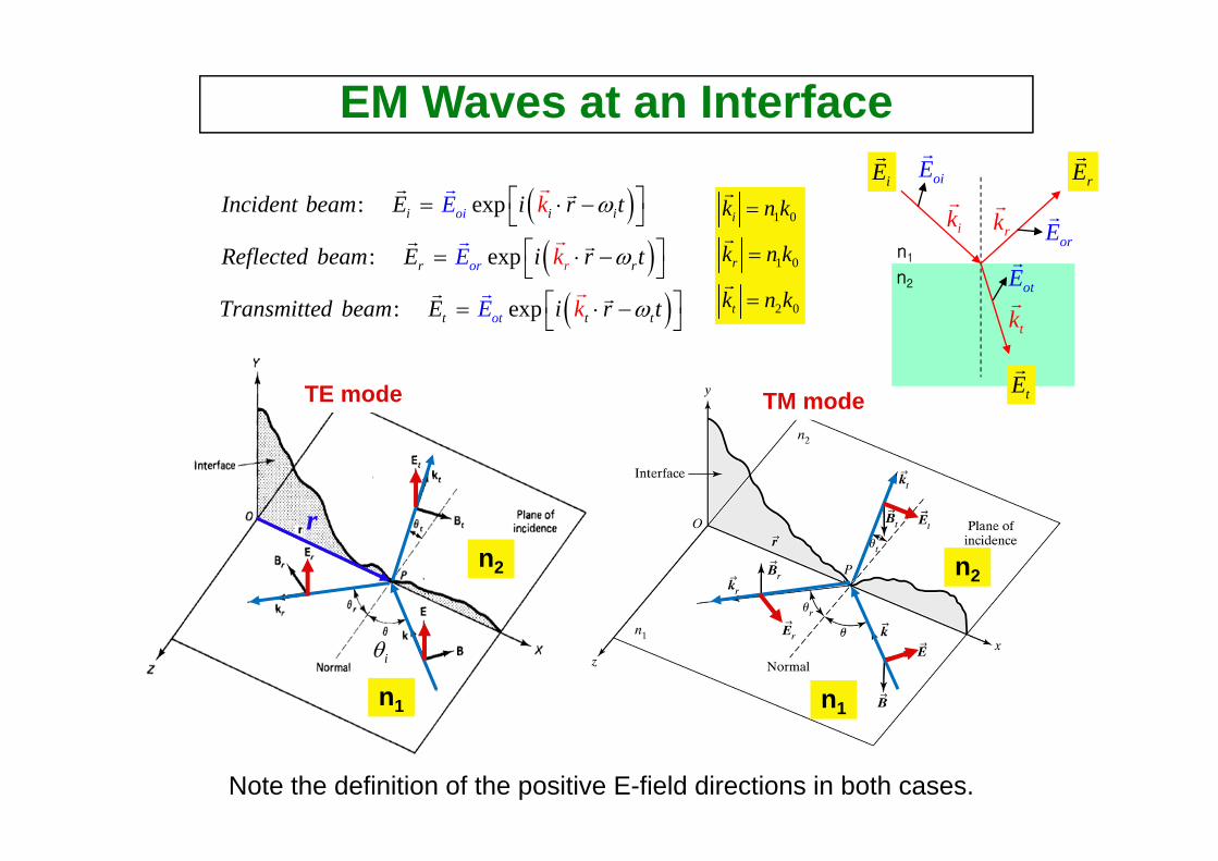
EM Waves at an Interface
( )( )( )
: exp
: exp
: exp
oi
or
i i i
r r
tt
r
tot
k
k
k
Incident beam E i r t
Reflected beam E i r t
Tran
E
E
smitted beam E i tE r
ω
ω
ω
⎡ ⎤= ⋅ −⎣ ⎦⎡ ⎤= ⋅ −⎣ ⎦⎡ ⎤= ⋅ −⎣ ⎦
rr r r
r r
r rr
r
r
r1 0
1 0
2 0
i
r
t
k n k
k n k
k n k
=
=
=
r
r
r
r
TE mode
n1
n2
iθ
n1
n2
TM mode
Note the definition of the positive E-field directions in both cases.
n2
n1
iEr
rEr
tEr
ikr
rkr
tkr
oiEr
orEr
otEr

EM Waves at an Interface
( ), ,
points
, the tangential component must be equal on both sides of the inter
At the boundary between the two media the x y plane all waves must exist simultaneouslyand .Therefore for all time t and fo
fall
acboundary r on th te
er e in
−
r ,rface
( )( )( )
exp
exp
exp
:
:
:
i oi i
r or
i
r
t ot t
r
t
E E i r t
E E i r
Incident beam
Reflected beam
Transmitted bea
k
k
km
t
E E i r t
ω
ω
ω
⎡ ⎤= ⋅ −⎣ ⎦⎡ ⎤= ⋅ −⎣ ⎦⎡ ⎤= ⋅ −⎣ ⎦
r r r
r r r
r r r
r
r
r
( ) ( ) ( ) : Phase matching at the boundary
,
!
:
i i r r t t
the only way that this can be true over the entire interfac
k r t k r t k r t
e and for all t is iAssuming that the wave amplitudes are constan
ft
ω ω ω⇒ ⋅ − = ⋅ − = ⋅ −r r rr r r
( ) ( ) ( )exp exp expoi i i or r r ot t
i r t
tn E i k r t n E i k r t n E i k
n E n E n
r t
E
ω ω ω⎡ ⎤ ⎡ ⎤ ⎡ ⎤× ⋅ − + ×
× +
⋅ − = × ⋅ −⎣ ⎦ ⎣ ⎦ ⎣ ⎦
× = ×r r rr r r
r r r) )
r r r) ) )
)n2
n1
iEr
rEr
tEr
ikr
rkr
tkr
oiEr
orEr
otEr
n̂
rr

EM Waves at an Interface
Normal
xikr
rkr
tkr
1 0n k
2 0n k
rr
1 0
1 0
2 0
i
r
t
k n k
k n k
k n k
=
=
=
r
r
r
( ) ( ) ( )Phase matching condition:
i i r r t tk r t k r t k r tω ω ω⋅ − = ⋅ − = ⋅ −r r rr r r
(Frequency does not change at the boundary!)
0,
t
i t
i r
r
At r this results int t tω ω ω
ω ω ω
== =
⇒ = =
r
, ,
, ,
,
and .
, .i r
i r t
i r
t
t
k r constant
the equation for a plane perpendicular to k
k k and k are coplanar in the plane of incidence
r
⇒ ⋅
⇒
=
→
r r
r
r
r
r r
(Phases on the boundary does not change
,
!)
0
i r t
At t this
k r
results i
k k
n
r r⋅ =
=
=⇒ ⋅ ⋅r r rr r r
n2
n1
iEr
rEr
tEr
ikr
rkr
tkr
rr

EM Waves at an Interface
co
0,
,
sin si
ns
n
,
sin
ta
s
n
n
t
i
i r i i r r
i
ii r
t
r i ri
r
At t
Considering the relation for the incident and reflected beams
k r k r k r k r
Since the incident and reflected beams are in t
k r k r
he same mediumnk k
k r
c
θ θ
ω θ θ θ θ
=
⋅ = ⋅ ⇒ =
= = ⇒ = ⇒
⋅ = ⋅ =
=
⋅ =
r rr r
r r rr r r
: law of reflection
,
sin sin
sin sin : law of refractio
,
n
i t i
i i t
i t t
i tt ti
Considering the relation for the incident and transmitted beams
k r k r k r k r
But the incident and transmitted beams are in different median nk k
c cn n
θ θ
ω θω θ=
⋅ = ⋅ ⇒ =
= = ⇒
r rr r
iθ
rθ
tθ
Normal
xikr
rkr
tkr
1 0n k
2 0n k
rr
n2
θι θr
θt
n1 x
iEr
rEr
tEr
ikr
rkr
tkr

Development of the Fresnel Equations
cos co
' ,
s co
:
si r t
i i r r t t
E E EB B B
From Maxwell s EM field theorywe have the boundary conditions at the interface
Th tangential
components of both E and B are equal onboth sides o
e above co
f the i
nditions imply that th
for the T
e
E case
θ θ θ+ =
− =
r r
0
cos cos
.,
c
:
os
.
i i r r t t
i t
i r t
We have alsoassumed that as is true formost dielectric materia
nterface
E E EB
For the TM mod
B B
e
ls
θ θ θ
μ μ μ
+ =− + = −
≅ ≅
TE-case
TM-case

Development of the Fresnel Equations
1
1 1
1
2
2
1
:
cos cos
:
cos cos c
v
s
c
o
os
i i r
i r t
i
r t t
i
i r r t t
cRecall that E B Bn
Let n refractive index of incident mediumn refractive index of refracting me
For the TM m
diu
For the TE mod
nEBc
ode
E E
e
E E En E n E E
n
m
n
En E E
θ θ
θ θ θ
θ
=⎛ ⎞= = ⇒⎜ ⎟⎝ ⎠
==
−
+
+
=
+
−
=
=
2r tn E= −
TE-case
TM-case
n1
n2
n1
n2

Development of the Fresnel Equations
2
1
sin sin
cos cos:cos cos
cos cos:cos co
:
s
cos
i trT
t
i t
Ei i t
i trTM
i i t
from each set of e
nETE case rE n
nETM ca
quationsand solving for the refleEliminating
ction coefficient we obtain
wher
E
nne
We know t
se rE
n
a
n
t
n
n
h
θ
θ θ
θθ
θ θθ θ
θ
θ−
= =+
− += =
=
=
+
22 2 2
2
sin1 sin 1 sinit t in n n
nθθ θ= − = − = −
TE-case
TM-case
n1
n2
n1
n2

TE-case
TM-case
n1
n2
n1
n2
Now we have derived the Fresnel Equations
2 2
2 2
2 2 2
2 2 2
cos sin
cos si
:
:
:
:
n
cos sin
cos sin
i irTE
i i i
i irTM
i i i
Substituting we obtain t reflection coefficiehe Fresnel equa nts r
nErE n
n nErE n
transmission c
tions for
TE case
TM case
For the
T
oeffici n t
n
e t
θ θ
θ θ
θ θ
θ θ
− −= =
+ −
− + −= =
+ −
2 2
2 2 2
2coscos sin
2 cos
: 1:
cos sin
1
:
:
TE TE
TM T
t iTE
i i i
t iTM
i
M
i i
E case
TM ca
EtE
TE t rTM n
nE ntE n
t
nse
r
θ
θ θθ
θ θ
= =+ −
= =
+= −
+ −
=
1
2
nnn ≡
These just mean the boundary conditions.
::i r t
i r t
For the TE case E E EFor the TM mode B B B
+ =− + = −
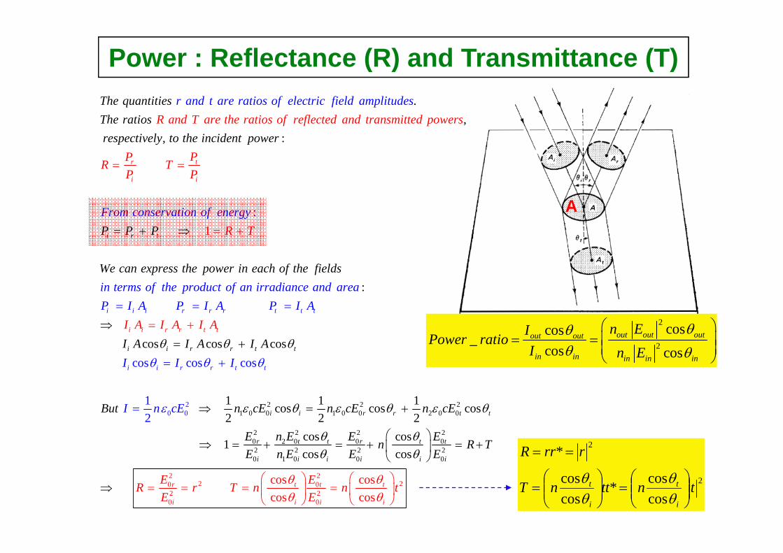
Power : Reflectance (R) and Transmittance (T).
1
,,
:
:
tr
i i
i r t
R and T are the ratios of reflected and transmitThe quantitiesThe ratiosrespectively to
ted powers
PPR TP P
R T
r and t are ratios of electric field amplitudes
From conservation of ener
the incident power
P P P
We can
gy
= =
= += + ⇒
21 0
20 00
:
cos cos
cos cos cos
1
cos
1 c22
i i i r r r t t t
i i r r
i i r r t
i i r r t
i
t
t
t t
iexpress the power in each of the fie
n terms of the product of an irradiance and areaP I A P I A P I A
I
lds
I A I A I A
But n c
I I
I n c
I A I I A
E
A
E
θ θ θ
ε
θ θ θ
ε
=⇒=+
=+
⇒
= = =
+
= 2 21 0 0 2 0 0
2 2 2 20 2 0 0
2 220 0
2 20 0
02 2 2 20 1 0 0 0
1 1os cos cos2 2
cos cos 1cos
cos coscos
co
s
s
co
i
r t t t
i i
r r t t
r t t r t t
i i i i
i
i i
i
n cE n cE
E n E E E
E ER r T n
n R TE
E
n E E
nE
E
θ ε θ ε θ
θ θθ
θ θθ θ
θ⎛ ⎞ ⎛ ⎞
=
= +
⎛ ⎞⇒ = + = + = +⎜ ⎟
⎝ ⎠
= = =⎜ ⎟ ⎜⎝ ⎝
⇒⎠ ⎠
2t⎟2
2
coscos*
coscos
*
tnttnT
rrrR
i
t
i
t⎟⎟⎠
⎞⎜⎜⎝
⎛=⎟⎟
⎠
⎞⎜⎜⎝
⎛=
==
θθ
θθ
2
2
coscos_cos cos
out out outout out
in in in in in
n EIPower ratioI n E
θθθ θ
⎛ ⎞= = ⎜ ⎟
⎜ ⎟⎝ ⎠
A

23-2. External and Internal Reflection
( )2 1
2 22 1
,
/ 1 sin 0
are always realTE TM
n n n n
r
n n
θ
⇒
⇒
>
= > ⇒ − ≥
⇒
rTE
t
n=1.50
Brewster’s angle (or, polarizing angle)(No reflection of TM mode)( ) 1
:
tan 0TM p p
fNo or tht e TM case
n
e
r whenθ θ θ −=⇒ = =
External Reflection
, 0TE TMr >
, 0TE TMr <
, 0TE TMt >2 2
2
2 2
2
2
2 2 2
cos sin
c
cos sin
co os sins sini ii
TM
i
iTE
i ii
n nr
n
nr
nn
θ θ
θ
θ θ
θ θθ
− + −=
+ −
− −=
+ −
, If 0 then there are no phase changes after reflection.TE TMr⇒ >
,
, , ,
If 0 then there are always ( 180 ) phase changes.
TE TM
TE TM TE TE Mi
TM T
r
er r rπ
π⇒ < =
→ = =−
o
[ ]2 1/ 1n n n= >
rTM

( )2 2,
,
, ,
, If sin 0, =1,
=1
(- ~ ) phase change may occur after reflect
ion
!TE TTE TM
TE TM
i iTE TM TE
M
TM
BUT r are compn r
r
r r e e
lex
φ φ
θ
φ π π
⇒ − <
→
→ = =
→ +
( )1tan
: 0p
TM
No Brewster's angle n
for the TM
e
case
t
r
θ −=
=
critical angle
Internal Reflection
2 2
2
2 2
2
2
2 2 2
cos sin
c
cos sin
co os sins sini ii
TM
i
iTE
i ii
n nr
n
nr
nn
θ θ
θ
θ θ
θ θθ
− + −=
+ −
− −=
+ −
, 0TE TMr >
, 0TE TMr <
Total internal reflection (TIR) when θ > θc
TIR region
( ) ( )21
2 2
2 1
2 2
/ 1
sin 0, , sin 0
n n n
n o
n n
r nθ θ
⇒ = <
⇒ − > − <
>
( )2 2,
2 1
If sin 0, =1
sin ( / )TE TM
c
n r
n n n
θ
θ
⇒ − =
→ = =
( )2 2,
,
,
If sin 0, are always real
If 0 then there are no phase changes after reflection.
If 0 then there are ( 180 ) phase changes.
TE TM
TE TM
TE TM
n r
r
r
θ
π
⇒ − >
→ >
→ < = o
[ ]2 1/ 1n n n= <

Derivation of Brewster’s Angle
( )
4 2 2 2
2 2 2
4 2 2 2
1
2 2 2
2 2 2 2
c
( ) :
cos sin
cos s
os sin0
cos sin
1.50, 56.
in
( 1) os si
tan
n 0
31
p
p p
p pTM p
p p
p
p
p p
p p
Brewster's angle for polarizing ang
n nr
n n
For n
le
n n
n n
n n c
n
θ
θ θ
θ θ
θ θθ
θ
θ
θ
θ
θ
θ
−
⇒ = −
− +
− + −= =
⎡ ⎤= − − =⎣
+
= =
=
⎦
−
⇒
°
externalreflectioninternal
reflection
θp θp
θc
R
External & Internal reflections, but TM-polarization only
1 : sin n nc <=θ
or nn np 11 : tan <>=θ
TE & TM polarizations, but Internal reflection only
Brewster ‘s angle :
Critical angle :
TE TM

Total Internal Reflection (TIR) 2
1
1 , ,and for both (TE and TM) cases.
sin t
: 1
1otal internal r
* 1
eflection( )
cos
rTE
i
c
nInternal reflection nn
r R rr is a complex
call
numb
eFor n TId
er
ErE
r
Rθ θ −
⇒
= <
= = =
≥
=
=
⇒
=2 2
2 2
2 2 2
2 2 2
sin
cos sin
cos sin
cos sin
i i
i i
i irTM
i i i
i n
n
n nErE n
i
i n
i
θ θ
θ θ
θ θ
θ θ
− −
+ −
− + −= =
+ −
internalreflection
R
r
θc
Complex value
R = 1

rTEn=1.50
, 0TE TMr >
, 0TE TMr <
, 0TE TMt >
23-3. Phase changes on reflection
,
,
,
18
,
,0
) 0
0
.0 (
TE T
TE TM
TE TM
Mthe phase
r is always a real numb
the
er for ex
phase sh
shift is fo
ift is
ternal reflection
then
an for r
r
d
r
π
° >
° = <
TE TM
Phase shift after External Reflection
For TE case, π phase shift for all incident angles For TM case, π phase shift for θ < θpNo phase shift for θ > θp
External Reflection External Reflection
External reflection
rTM

cθθ >:
Complex value
In TIR region
Phase shift after Internal Reflection Internal reflection
1 0 for sin is complex in TIR region where
TE TE
TE c
TE ci i
TE TE
r nr
r r e eφ φ
θ θθ θ
−⇒ > < =⇒ >
→ = =
For TM case, no phase shift for θ < θpπ phase shift for θp < θ < θc
φTM(θ) phase shift for θ > θc
For TE case, no phase shift for θ < θc
φTE(θ) phase shift for θ > θc
TIR TIR
1 0 for tan
0 for
TM
TM p
TM p c
iTM TM TM TM
r n
r
r r e rφ
θ θ
θ θ θ
φ π
−⇒ > < =
⇒ < < <
→ = − = → =
is complex in TIR region where
TM TM
TM ci i
TM TM
r
r r e eφ φ
θ θ⇒ >
→ = =

2
:
cos sin sintancos sin
2
( )
s
co
ii i
i
c TIWhen then and for both the TE and TM cases has the form
a ib i e br e ea ib i
R case r is complex
e a
αα φ
α
α α α φ ααα
θ θ
α α
−−
+
− −= = = =
≥
== = −= ⇒+ +
2 2
2 2
2 2
2
1
2 2
2
cos sin:
cos sin
cos sin
sintan t
( ).
sin2 tan
co
an2 cos
s
i irTE
i i i
i i
iT
i
E
TEi
is the phase shift on total internal reflection TIR
n
i nETE case rE i n
a b n
n
A simi
φ
θ θ
θ θ
θ θ
θφ
θ
θφαθ
−
− −= =
+ −
= = −
−⎛ ⎞
⎛ ⎞−⎜ ⎟= −⎜ ⎟
⇒ = − =⎜⎝ ⎠
⎝ ⎠
⎟
2 21
2
sin2 tan
cos
:
iTM
i
lar analysis for the TM case giv
n
es
nθφ π
θ−⎛ ⎞−⎜ ⎟= −⎜ ⎟⎝ ⎠
Internal reflection
: i cθ θ>
: i cθ θ>
TIR(Complex r )
Phase shifts on total Internal Reflection for both TE- and TM-cases

2 21
2
2 21
sin2 tan
cos
sin2 tan
cos
iTM
iTE
nn
n
θφ π
θ
θφ
θ
−
−
⎛ ⎞−⎜ ⎟= −⎜ ⎟⎝ ⎠
⎛ ⎞−⎜ ⎟= −⎜ ⎟⎝ ⎠
Internal reflection
Complex value
Therefore, after TIR is ……….. ,TE TMr
,TE TMr
,TE TMφ
2 2
2 2
2 2 2
2 2 2
cos sin
cos sin
cos sin
cos sin
i irTE
i i i
i irTM
i i i
nErE n
n n
i
i
in n
i
ErE
θ θ
θ θ
θ θ
θ θ
− −= =
+ −
− + −= =
+ −
( )cincident θθ > case TIRFor

Internal reflectionTIR(Complex r )
Summary of Phase Shifts on Internal Reflection
'p
'p c
2 21
c2
0 <
( 180 ) <
sin2 tan <
cos
TM
i nn
θ θ
φ π θ θ θ
θπ θ θ
θ−
⎧⎪⎪⎪⎪= = <⎨⎪ ⎛ ⎞−⎪ ⎜ ⎟−⎪ ⎜ ⎟⎪ ⎝ ⎠⎩
o
o
p
p c
c
0 <
<
0 TM TE
θ θ
φ φ φ π θ θ θ
θ θ
⎧=⎪
Δ = − = <⎨⎪> <⎩
o
o
c
2 21
c
0 <
sin2 tan >
cosTE i n
θ θ
φ θθ θ
θ−
⎧⎪⎪ ⎛ ⎞= −⎨ ⎜ ⎟−⎪ ⎜ ⎟⎪ ⎝ ⎠⎩
o
φΔTMφ
TEφ

Fresnel Rhomb
Linearly polarized light (45o)
CircularlyPolarized
light
3 53 1.54
After two consequentive TIRs, 3 2
2
TM TE i
TM TE
TM TE
Note near when n
Quarter wave retarder
πφ φ θ
πφ φ
πφ φ φ
− = = =
→
→ − =
→ Δ = − =
→ −
o
φΔTMφ
TEφ

Linearly polarized light
(45o)
CircularlyPolarized
light
69 ???2
2
TM TE i
TM TE
Note near when n
Quarter wave retarder
πφ φ θ
πφ φ φ
− = = =
→ Δ = − =
→ −
oφΔTMφ
TEφ
Quarter-wave retardation after TIR
n

23-5. Evanescent Waves at an Interface
( )( )( )
( )
: exp
: exp
: exp
exp
si
:
n
i oi i i
r or r r
t ot t t
t ot t t
t t t
Incident beam E E i k r t
Reflected beam E E i k r t
Transmitted beam E E
For the transmitted
i k
bea
r t
E E i k r
k
m
t
r k
ω
ω
ω
ω
θ
⎡ ⎤= ⋅ −⎣ ⎦⎡ ⎤= ⋅ −⎣ ⎦⎡ ⎤= ⋅ −⎣ ⎦
⎡ ⎤= ⋅ −⎣ ⎦
⋅ =
rr r r
rr r r
rr r r
r r
r r )( ) ( )( )
2
22
cos
sin cos
sin, cos 1 sin 1
, :
sin
sinc
( )
o s 1it
t t
t t t
it t
iWhen n
x k z x x zz
k x z
Butn
th
i a purely imaginary numbe
total internal reflection
r
en
n
θ
θ
θθ
θ
θθ
θ
θ
+ ⋅ +
= +
=
= −
− −
⇒
=
>
)) )

Evanescent Waves at an Interface( )
2
2 2
sin
sin 1
,:
sin
:
sin sin21 1
:
tt t
it
i
i
t
t
iwith an TIR condition n
i z
For the transmitted beamwe can write the phase factor as
k r k xn
Defining the coefficient
kn n
We can write the transmitted wa s
n
v
E
e a
θ
α
θ θπαλ
θ
θ⎛ ⎞⋅ = +⎜ ⎟
⎜ ⎟⎝ ⎠
=
−
− −
=
=
>
r r
( )0sin ep
.
xx pe t tt z
amplitude will decay rapidThe evanescent waveas it penetrates into the lower refractive ind
ly
k xE i t
ex med
n
ium
θ ω α⎡ ⎤⎛ ⎞− −⎜ ⎟⎢ ⎥⎝ ⎠⎣ ⎦
Note that the incident and reflection wavesform a standing wave in x direction
n2
n1
n1 > n2 h
( )0sinexp expt t
t tk xE E i t z
nθ ω α⎡ ⎤⎛ ⎞= − −⎜ ⎟⎢ ⎥⎝ ⎠⎣ ⎦
x
z
2
2
1 1sin2 1
t ot
i
E Ee
h
n
λα θπ
⎛ ⎞= ⇒ = =⎟⎝ ⎠
−⎜Penetration depth:
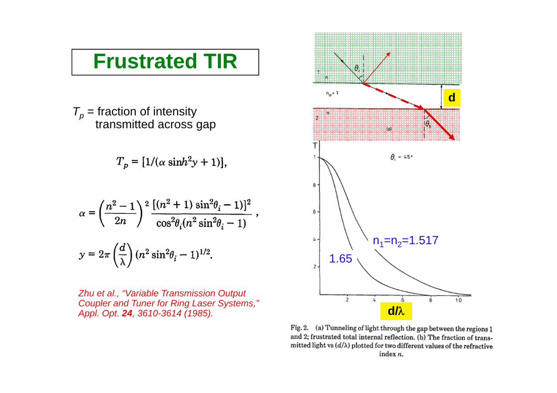
Frustrated TIR
Tp = fraction of intensity transmitted across gap
Zhu et al., “Variable Transmission Output Coupler and Tuner for Ring Laser Systems,” Appl. Opt. 24, 3610-3614 (1985).
d
n1=n2=1.5171.65
d/λ

Frustrated Total Internal Reflectance
Zhu et al., “Variable Transmission Output Coupler and Tuner for Ring Laser Systems,” Appl. Opt. 24, 3610-3614 (1985).
Pellin-Broca prism
d = 1 ~ λ: changing the reflectanceRotation: changing the wavelength resonant at θB
d

23-6. Complex Refractive Index
2 2 2
0
0
( ) :
1
1
2R I R I
R IFor a material with conductivity
n i n n i n
n i n i n
n
σε ω
σ
σε ω
⎛
⎛ ⎞= + = −
⎞= + = +⎜ ⎟
⎝ ⎠
+⎜ ⎟⎝ ⎠
%
%
2
0
2
02 2
2 4 2
0 0
2
0
2
022
:
1 2
1 02 2
:
1 1
2
1 1 42
42
2 2
RI
I
R I R I
I I II
I
Solving for the real and imaginary components we obtain
n n n n
n n nn
From the quadratic solution we obt
nn
n
ain
n
σε ω
σ σε ω ε ω
σε
σε
σω
ω
ε ω
− = = ⇒
⎛ ⎞ ⎛ ⎞⇒ − = ⇒ − − =⎜ ⎟ ⎜ ⎟
⎝ ⎠ ⎝ ⎠
⎛ ⎞± +
=
⎛ ⎞+ + ⎜ ⎟
⎝⎜⎝ =⇒ ⎠
⎟⎠=
.IWe need to take the positive root because n is a real number

Complex Refractive Index
( )( ) ( )
( )
0
0
0
exp
ˆexp
eˆ xexp pRk
R k
I
I
Substituting our expression for the complex refractive index back intoour expression for the electric field we obtain
E E i k r t
E i n i n u r tc
E ni u r tc
nc
ω
ω
ω
ω
ω
⎡ ⎤= ⋅ −⎣
⎧ ⎫⎡ ⎤⋅ − −
⎦⎧ ⎫⎡ ⎤= + ⋅ −⎨ ⎬⎢ ⎥
⎨ ⎬⎢ ⎥⎣ ⎦
⎣ ⎦⎭
⎩
⎩
=⎭
rr
r
r r
r r
r( )
..
ˆ
/
k
R
The first exponential term is oscillatoryThe EM wave propagates w
u r
The second exponential has a r
ith a ve
eal arg
locity of
ument (absor .
n c
bed)
⎡ ⎤⋅⎢ ⎥⎣ ⎦
r

Complex Refractive Index
( )* *0 0
0
..
ˆ2exp
ˆ2exp
I k
I k
The second term leads to absorption of the beam in metals due to inducinga current in the medium This causes the irradiance to decrease as the wavepropagates through the medium
n u rI EE E E
c
n uI I
ω
ω
⋅⎡ ⎤≡ = −⎢ ⎥
⎣ ⎦
= −
rr r r r
( ) ( )0 ˆexp
2 4:
k
I I
rI u r
c
The absorption coefficient is defined n ncω πα
α
λ
⋅⎡ ⎤= − ⋅⎡
= =
⎤⎢ ⎥ ⎣ ⎦⎣ ⎦
rr
( ) ( )0 ˆex ˆexpp Ik k
R n uni u rc
rtc
E E ω ω⎧ ⎫⎡ ⎤⋅ −⎨ ⎬⎢ ⎥⎡ ⎤− ⋅=
⎣ ⎦⎩ ⎢ ⎥⎣ ⎦⎭
rr r r

23-7. Reflection from Metals
2 2
2 2
2 2 2
2 2 2
cos sin:
cos sin
cos sin:
cos sin
:
i irTE
i i i
i irTM
i i i
Reflection from metals is analyzed
ETE case rE
nETM cas
by substituting the complex refractive index n i
e rE n
S
n the Fresnel
n
n
equa
ub
ti
n
n
n
o s
s
θ θ
θ θ
θ θ
θ θ
− −= =
+ −
− + −= =
+ −
%
%
%%
%
% %
( ) ( )
( ) ( )
( ) ( ) ( ) ( )
( ) ( ) ( ) ( )
2 2 2
2 2 2
2 2 2 2 2
2 2 2 2 2
:
cos sin 2:
cos sin 2
2 cos sin 2:
2 cos sin 2
i R I i R Ir
i i R I i R I
R I R I i R I i R Ir
i R I R I i R
R I
I i R I
TE case
TM case
tituting we obtain
n n i n nErE n n i n n
n n i n n n n i n nErE n n i n n n n
n n i
i n n
n
θ θ
θ θ
θ θ
θ θ
− − − += =
+ − − +
⎡ ⎤− − + + − − +⎣ ⎦= =⎡ ⎤− + + − +
=
⎣
+
−⎦
%
Reflectance
θi

Reflection from Metals at normal incidence (θi=0)
( )( )
( )( )
( )( )
( )( )
2 2
2 2
*
2 2
2 2
1 1 1 2 1 1
1
1
1
1
1
2
R I
R I R I R R I
R I R I R R
R I
R I
I
R I
The is given by
R r r
n i n n i n n n nn i n n i n n n n
power refl
n i nr
n i
ectance R
n
n nR
n n
∴
=
⎡ ⎤ ⎡ ⎤− − − + ⎛ ⎞− + += =⎢ ⎥ ⎢ ⎥ ⎜ ⎟+ − + + + + +⎝ ⎠
− +=
+
− −=
+ −
⎦
+
⎣ ⎣ ⎦
2 2
2 2
2 2 2
2 2 2
cos sin 11cos sin
cos sin 11cos sin
i iTE
i i
i iTM
i i
nrn
n n
n
n
nr
nn n
θ θ
θ θ
θ θ
θ θ
− − −= =
++ −
− + − −= =
++ −
%
%
% % %
%
%
% %
%
, 0 :iAt normal incidence θ = ° At normal incidence(from Hecht, page 113)
λ
visible