Embed Size (px)
Citation preview
Prepared by:
803 Summer Street Boston, MA 02127
This image cannot currently be displayed.
STORMWATER REPORT
4TH AVENUE REDEVELOPMENT
NORDBLOM COMPANY 71 THIRD AVENUE
BURLINGTON, MASSACHUSETTS
JUNE 6, 2016
Applicant:
NORDBLOM COMPANY 71 THIRD AVENUE BURLINGTON, MA
BSC Job Number: 23158.33
Stormwater Report174/186 Middlesex Turnpike
Burlington, Massachusetts
TABLE OF CONTENTS
PAGE NUMBER
1.0 PROJECT NARRATIVE 1.01 PROJECT DESCRIPTION 1 1.02 PRE-DEVELOPMENT DRAINAGE CONDITIONS 2 1.03 POST-DEVELOPMENT DRAINAGE CONDITIONS 2
2.0 LONG-TERM POLLUTION PREVENTION AND OPERATION & MAINTENANCE PLAN 8
3.0 CONSTRUCTION PERIOD EROSION AND SEDIMENT CONTROL PLAN 12
4.0 PEAK RUNOFF RATE CALCULATIONS 30
4.01 EXISTING CONDITIONS WATERSHED ANALYSIS PLAN 4.02 EXISTING CONDITIONS HYDROCAD PRINTOUTS 4.03 PROPOSED CONDITIONS WATERSHED ANALYSIS PLAN 4.04 PROPOSED CONDITIONS HYDROCAD PRINTOUTS
5.0 PIPE SIZING CALCULATIONS
6.0 ADDITIONAL DRAINAGE CALCULATIONS
6.01 STORAGE DRAWDOWN CALCULATIONS 6.02 WATER QUALITY UNIT SIZING INFORMATION 6.03 TSS REMOVAL CALCULATIONS 6.04 COMPENSATORY STORAGE ANALYSIS
APPENDICES
ORDER OF RESOURCE AREA DELINEATION SOIL SURVEY MAP STORMWATER REPORT CHECKLIST

Stormwater Report174/186 Middlesex Turnpike
Burlington, Massachusetts
SECTION 1.0
PROJECT NARRATIVE
Stormwater Report174/186 Middlesex Turnpike
Burlington, Massachusetts
1
1.01 PROJECT DESCRIPTION
The site is located at 174/186 Middlesex Turnpike within Northwest Park in Burlington, Ma. The site is bounded by 186 Middlesex Turnpike (Building 33) to the north, Building 23 in Northwest park to the west, Fourth Avenue to the south and Middlesex Turnpike to the east.
The property is part of Northwest Park (NWP) and is identified as a portion of development “Area B” in the Northwest Park Planned Development District (“PDD”) dated January 22, 2007 and approved January 24, 2007 by Burlington Town Meeting. Abutting the project site is the portion of the Northwest Park PDD identified as “Area A,” which was recently redeveloped. Refer to the PDD for a more comprehensive summary of zoning provisions for Area A and the overall planned development.
The proposed redevelopment of the site will include the construction of a five story 240,000 square foot office building with associated access drives, parking areas and utility improvements.
The proposed redevelopment will result in an increase in impervious area thereby resulting in an increase in Stormwater runoff. To reduce the impacts of increased runoff a Stormwater management system is included as part of the development’s design. The Stormwater management system includes hooded catch basins with deep sumps, proprietary water quality units for Total Suspended Soils (TSS) removal and underground detention systems to contain and release the Stormwater in a controlled fashion.
The proposed project has been designed to comply with the Massachusetts Wetland Protection Act (310 CMR 10.00) regulation and the Departments of Environmental Protection’s Stormwater Management Standards.
Stormwater Report174/186 Middlesex Turnpike
Burlington, Massachusetts
2
1.02 PRE-DEVELOPMENT DRAINAGE CONDITIONS
The site is located at 174/186 Middlesex Turnpike in Burlington, Massachusetts. The project site consists of the existing single story Building 23 (+/-30,600 sf) and the site of the former Building 15 (+/-61,302 sf) and associated parking areas within Northwest Park.
The existing site is approximately 8.06 acres within Northwest Park. Approximately 5.08 acres of the site consist of impervious surfaces, including 2.11 acres of building roof and 2.97 acres of paved areas. The remaining 2.98 acres is currently pervious open space, including grass islands.
Existing grades range from elevation 137 along the northwest property line to 126 along Middlesex Turnpike. A majority of the existing site is impervious area consisting of the existing building 23 and former building 15 with associated paved parking areas. Stormwater runoff is collected in catch basins and discharges to the municipal drainage system in Fourth Avenue and Middlesex Turnpike via several piped connections.
Existing historic soils on the site are detailed in current Natural Resources Conservation Service (NRCS) online databases, and show the site is listed as ‘Urban Land’ which is unclassified. Based on the surrounding soil types the Urban Land has been designated as HSG C.
1.03 POST-DEVELOPMENT DRAINAGE CONDITIONS
Specifics of the proposed site stormwater management are as follows:
Under the post development conditions there is an increase of impervious area of 0.61 acres. The runoff from the front parking lot is captured in a series of deep-sump hooded catch basins and passes through proprietary water quality units (WQU’s) prior to discharging to a subsurface detention system. The rooftop runoff from the office building is collected and discharges to the subsurface detention system. An outlet control structure allows the subsurface detention system to hold the Stormwater runoff and discharge at a controlled rate to the existing piped connection to the Fourth Avenue drainage system. The runoff from the remainder of the site is collected in a series of deep-sump hooded catch basins and passes through proprietary water quality units (WQU’s) prior to discharging to the municipal drainage system via existing piped connections. All stormwater runoff from pavement areas will be treated in deep sump and hooded catch basins and routed through water quality units to achieve a Total Suspended Solids (TSS) removal in excess of 80%. Standard 1 - New Stormwater Conveyances
Per Massachusetts Stormwater Management Standard #1, no new outfalls may discharge untreated stormwater directly to or cause erosion in wetlands or waters of the Commonwealth. The project proposes to discharge to existing connections to the municipal drainage system.
Standard 2 - Stormwater Runoff Rates
The stormwater management system has been designed such that the post-development conditions result in a decrease in the peak runoff rates for the entire site. The reduction in peak runoff rates is
Stormwater Report174/186 Middlesex Turnpike
Burlington, Massachusetts
3
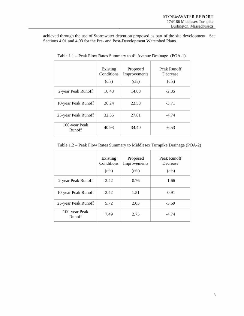
achieved through the use of Stormwater detention proposed as part of the site development. See Sections 4.01 and 4.03 for the Pre- and Post-Development Watershed Plans.
Table 1.1 – Peak Flow Rates Summary to 4th Avenue Drainage (POA-1)
Existing
Conditions
(cfs)
Proposed Improvements
(cfs)
Peak Runoff Decrease
(cfs)
2-year Peak Runoff 16.43 14.08 -2.35
10-year Peak Runoff 26.24 22.53 -3.71
25-year Peak Runoff 32.55 27.81 -4.74
100-year Peak Runoff
40.93 34.40 -6.53
Table 1.2 – Peak Flow Rates Summary to Middlesex Turnpike Drainage (POA-2)
Existing
Conditions
(cfs)
Proposed Improvements
(cfs)
Peak Runoff Decrease
(cfs)
2-year Peak Runoff 2.42 0.76 -1.66
10-year Peak Runoff 2.42 1.51 -0.91
25-year Peak Runoff 5.72 2.03 -3.69
100-year Peak Runoff
7.49 2.75 -4.74
Stormwater Report174/186 Middlesex Turnpike
Burlington, Massachusetts
4
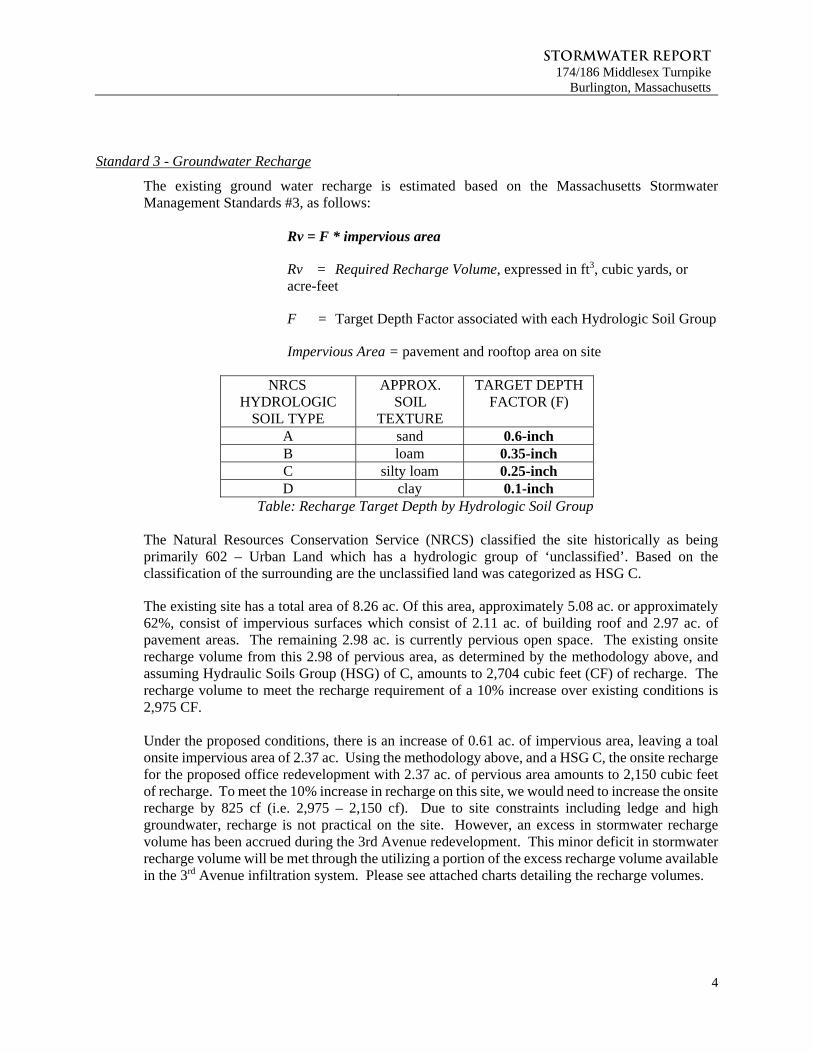
Standard 3 - Groundwater Recharge
The existing ground water recharge is estimated based on the Massachusetts Stormwater Management Standards #3, as follows:
Rv = F * impervious area
Rv = Required Recharge Volume, expressed in ft3, cubic yards, or acre-feet
F = Target Depth Factor associated with each Hydrologic Soil Group
Impervious Area = pavement and rooftop area on site
NRCS HYDROLOGIC
SOIL TYPE
APPROX. SOIL
TEXTURE
TARGET DEPTH FACTOR (F)
A sand 0.6-inch B loam 0.35-inch C silty loam 0.25-inch D clay 0.1-inch
Table: Recharge Target Depth by Hydrologic Soil Group The Natural Resources Conservation Service (NRCS) classified the site historically as being primarily 602 – Urban Land which has a hydrologic group of ‘unclassified’. Based on the classification of the surrounding are the unclassified land was categorized as HSG C.
The existing site has a total area of 8.26 ac. Of this area, approximately 5.08 ac. or approximately 62%, consist of impervious surfaces which consist of 2.11 ac. of building roof and 2.97 ac. of pavement areas. The remaining 2.98 ac. is currently pervious open space. The existing onsite recharge volume from this 2.98 of pervious area, as determined by the methodology above, and assuming Hydraulic Soils Group (HSG) of C, amounts to 2,704 cubic feet (CF) of recharge. The recharge volume to meet the recharge requirement of a 10% increase over existing conditions is 2,975 CF. Under the proposed conditions, there is an increase of 0.61 ac. of impervious area, leaving a toal onsite impervious area of 2.37 ac. Using the methodology above, and a HSG C, the onsite recharge for the proposed office redevelopment with 2.37 ac. of pervious area amounts to 2,150 cubic feet of recharge. To meet the 10% increase in recharge on this site, we would need to increase the onsite recharge by 825 cf (i.e. 2,975 – 2,150 cf). Due to site constraints including ledge and high groundwater, recharge is not practical on the site. However, an excess in stormwater recharge volume has been accrued during the 3rd Avenue redevelopment. This minor deficit in stormwater recharge volume will be met through the utilizing a portion of the excess recharge volume available in the 3rd Avenue infiltration system. Please see attached charts detailing the recharge volumes.
Stormwater Report174/186 Middlesex Turnpike
Burlington, Massachusetts
5
Standard 4 - Water Quality
The stormwater management system has been designed to provide treatment for stormwater runoff from all the new impervious areas. A breakdown of water quality volumes/flow rates by subcatchment area, as well as proprietary water quality unit sizing calculations, are included in the Additional Drainage Calculations Section 6.0 of this report.
VWQ = (DWQ/12 inches/foot) * (AIMP * 43,560 square feet/acre) VWQ = Required Water Quality Volume (in cubic feet)
DWQ = Water Quality Depth: 1-inch. AIMP = Impervious Area (in acres) (Water Quality Provided by a StormCeptor Water Quality Inlet sized per the STEP Program)
The proposed stormwater management system has been designed to meet the Massachusetts Stormwater Handbook Standard #4 for the removal of a minimum of 80% Total Suspended Solids (TSS) to the extent practicable. This is achieved by the following Best Management Practices (BMP’s):
Deep sump and hooded catch basins (25%)
StormCeptor Water Quality Units (76%)
See Section 6.0 Additional Drainage Calculations for treatment train calculations
Standard 5 – Land Uses With Higher Potential Pollutant Loads (LUHPPL)
The Project will generate over a 1000 Vehicle Trips per day, therefore the project will implement Best Management Practices (BMPs) including; catch basins with deep sumps and hoods, stormceptor water quality units and a subsurface detention basins.
Standard 6 – Stormwater Discharges to a Critical Area
The project is not subject to Standard 6. There are no discharges to any Critical Areas as defined by the Stormwater Handbook. Please refer to NHESP Map located in the Appendices.
Standard 7 – Redevelopment Projects
The project is a redevelopment project as defined by DEP’s Massachusetts Stormwater Handbook, therefore the standards are required to be met to the maximum extent practicable. However, all standards are met to the maximum extent practicable.
Standard 8 – Sedimentation and Erosion Control Plan
A Sedimentation and Erosion Control Plan is included within the plan set as Sheet C-100 and a Construction Period Erosion and Sediment Control Plan is included in Section 3.0 of this Report.
Standard 9 – Long Term Operation and Maintenance Plan
A long-term operation and maintenance plan is included in Section 2.0 of this Report
Stormwater Report174/186 Middlesex Turnpike
Burlington, Massachusetts
6
Standard 10 –Illicit Discharges to the Stormwater Management System are prohibited
There are no known illicit discharges to the proposed Stormwater Management System and none are proposed.
Compensatory Flood Storage
Portions of the site fall within Bordering Land Subject to Flooding (BLSF, 100-year floodplain) designated on this property and approved under the Order of Resource Area Delineation issued March 20, 2008. The project involves some regrading within the flood plain and all areas have been compensated for on a foot by foot basis in accordance with the Massachusetts Wetlands Protection Act performance standards for Bordering Land Subject to Flooding. The enclosed compensatory storage calculations demonstrate that the site will not lose any ability to store flood waters, in total or at any given foot by foot increment. Calculations are provided in Section 6.04 Compensatory Storage Flood Calculations.
Conclusions
The project has been designed to meet to the maximum extent practicable the applicable provisions of the Stormwater Management Standards. Through the use of deep sump hooded catch basins, proprietary water quality units, underground structured detention systems, and along with nonstructural BMP’s (landscaping, etc.), the proposed development of the property has been designed to reduce the impacts to the surrounding resource areas and properties.
Stormwater Report174/186 Middlesex Turnpike
Burlington, Massachusetts
7
SECTION 2.0
LONG-TERM POLLUTION PREVENTION PLAN AND OPERATION &
MAINTENANCE PLAN
Stormwater Report174/186 Middlesex Turnpike
Burlington, Massachusetts
8
2.0 LONG-TERM POLLUTION PREVENTION & OPERATION AND MAINTENANCE
PLAN This Long-Term Pollution Prevention Plan has been developed for source control and pollution prevention at the site after construction.
MAINTENANCE RESPONSIBILITY
The enforcement of the Long-Term Operation and Maintenance Plan will be the responsibility of the Applicant, Nordblom Development Company, 71 Third Avenue, Burlington, MA, the owner of the property where the development is situated.
ILLICIT DISCHARGE STATEMENT
Illicit discharges to the Stormwater Management system are not allowed and are prohibited. The Applicant, Nordblom Development Company, is the responsible party.
GOOD HOUSEKEEPING PRACTICES
The site is to be kept clean of trash and debris at all times. Trash, junk, etc. is not to be left outside and will be subject to removal at the owner’s expense.
REQUIREMENTS FOR ROUTINE INSPECTIONS AND MAINTENANCE OF STORMWATER BEST
MANAGEMENT PRACTICES
All stormwater Best Management Practices (BMP’s) are to be inspected and maintained as follows:
Straw Wattles, Silt Fences, and other temporary measures
The temporary erosion control measures will be installed along the limits of work where any disturbance or alteration might otherwise allow for erosion or sedimentation. They will be regularly inspected (once/week and after rain events greater than 0.5 inches) to insure that they are functioning adequately. Additional supplies of these temporary measures will be stockpiled on site for any immediate needs or routine replacement. Deep Sump Hooded Catch Basins Regular maintenance is essential. Deep sump catch basins and trench drains remain effective at removing pollutants only if they are cleaned out frequently. Inspect or clean at least four times per year and at the end of the foliage and snow removal seasons. Sediments must also be removed four times per year or whenever the depth of the deposits in the catch basin sump is greater than or equal to one foot from the bottom of the basin. Proprietary Water Quality Units The proprietary water quality units (Stormceptor, or approved equal) will require periodic inspection and cleaning to maintain operation and function. Owners should have these units inspected on a quarterly basis and after periods of intense precipitation. While all inspections and maintenance shall be performed in accordance with the manufacturer’s written recommendations, the following can be used as a seasonal guideline. Inspections of the units can be done by using a clear Plexiglas tube (“sludge judge”) to extract a water column sample. When sediment depths exceed 12-inches or other depth recommended by the manufacturer, then cleaning of the unit is required.
These water quality units must and will be checked and cleaned immediately after petroleum spills. In the event of a spill, the appropriate regulatory agency must be notified.
Stormwater Report174/186 Middlesex Turnpike
Burlington, Massachusetts
9
Maintenance of these units should be done by a vacuum truck that will remove the water, sediment, debris, floating hydrocarbons and other materials in unit. The proper cleaning and disposal of the removed materials and liquid must be followed.
Inlet and outlet pipes must be checked for any obstructions and if any obstructions are found, they must be removed. Structural parts of the units will be repaired as needed.
Detention System Maintenance is required for the proper operation of the underground detention systems. Detention systems are prone to failure due to clogging if the upstream water quality units are not maintained. The use of pretreatment BMPs will minimize failure and maintenance requirements. After construction, the detention systems should be inspected after every major storm (greater than 0.5 inches) for the first few months to ensure proper stabilization and function. Water levels in the access ports should be recorded over several days to check the drainage of the systems. It is recommended that a log book be maintained showing the depth of water in the detention/infiltration systems at each observation in order to determine the rate at which the system dewaters after runoff producing storm events. Once the performance characteristics of the detention have been verified, the monitoring schedule can be reduced to an annual basis, unless the performance data suggests that a more frequent schedule is required. Preventive maintenance on the detention systems should be performed at least twice a year, or as recommended by the manufacturer, and sediment should be removed from any and all pretreatment and collection structures. Sediment should be removed when deposits approach within six inches of the invert heights or as recommended by the manufacturer.
SNOW DISPOSAL AND PLOWING
The purpose of the snow and snowmelt management plan is to provide guidelines regarding snow disposal site selection, site preparation and maintenance that are acceptable to the Department of Environmental Protection. For the areas that require snow removal, snow storage onsite will largely be accomplished by using pervious upland areas along the shoulder of roadways as windrowed by plows. Avoid dumping of snow into any water body, including rivers, ponds, or wetlands. In addition to
water quality impacts and flooding, snow disposed of in open water can cause navigational hazards when it freezes into ice blocks.
Avoid disposing of snow on top of storm drain catch basins or in stormwater basins. Snow combined with sand and debris may block a storm drainage system, causing localized flooding. A high volume of sand, sediment, and litter released from melting snow also may be quickly transported through the system into surface water.
WINTER ROAD SALT AND/OR SAND USE AND STORAGE RESTRICTIONS
Road salt and sand shall not be stored onsite.
Stormwater Report174/186 Middlesex Turnpike
Burlington, Massachusetts
10
STREET SWEEPING SCHEDULES
There are three types of sweepers: Mechanical, Regenerative Air, and Vacuum Filter.
1) Mechanical: Mechanical sweepers use brooms or rotary brushes to scour the pavement.
2) Regenerative Air: These sweepers blow air onto the road or parking lot surface, causing fines to rise where they are vacuumed.
3) Vacuum Filter: These sweepers remove fines along roads. Two general types of vacuum filter sweepers are available - wet and dry. The dry type uses a broom in combination with the vacuum. The wet type uses water for dust suppression
Regardless of the type chosen, the efficiency of street sweeping is increased when sweepers are operated in tandem.
It is recommended that street sweeping of the parking areas occur four times a year using a Regenerative Air or Vacuum Filter sweeper, including once after the spring snow melt.
Reuse and Disposal of Street Sweepings
Once removed from paved surfaces, the sweepings must be handled and disposed of properly. Mass DEP’s Bureau of Waste Prevention has issued a written policy regarding the reuse and disposal of street sweepings. These sweepings are regulated as a solid waste, and can be used in three ways:
In one of the ways already approved by Mass DEP (e.g., daily cover in a landfill, additive to compost, fill in a public way)
If approved under a Beneficial Use Determination
Disposed in a landfill
TRAINING OF STAFF OR PERSONNEL INVOLVED WITH IMPLEMENTING LONG-TERM POLLUTION
PREVENTION PLAN
The Long-Term Pollution Prevention Plan is to be implemented by property owner each individual lot. Trained and, if required, licensed Professionals are to be hired by the owner as applicable to implement the Long-Term Pollution Prevention Plan.
LIST OF EMERGENCY CONTACTS FOR IMPLEMENTING LONG-TERM POLLUTION PREVENTION
PLAN
The Owner will be required to maintain an updated list of Emergency Contacts for the site. This list will be provided during construction.
Stormwater Report174/186 Middlesex Turnpike
Burlington, Massachusetts
11
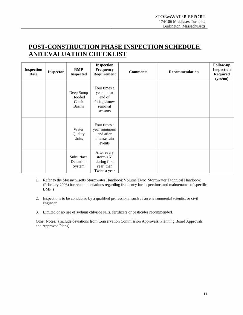
POST-CONSTRUCTION PHASE INSPECTION SCHEDULE AND EVALUATION CHECKLIST
Inspection Date
Inspector BMP
Inspected
Inspection Frequency
Requirements
Comments Recommendation
Follow-up Inspection Required (yes/no)
Deep Sump Hooded Catch Basins
Four times a year and at
end of foliage/snow
removal seasons
Water
Quality Units
Four times a
year minimum and after
intense rain events
Subsurface Detention
System
After every storm >5” during first year, then
Twice a year
1. Refer to the Massachusetts Stormwater Handbook Volume Two: Stormwater Technical Handbook
(February 2008) for recommendations regarding frequency for inspections and maintenance of specific BMP’s
2. Inspections to be conducted by a qualified professional such as an environmental scientist or civil
engineer.
3. Limited or no use of sodium chloride salts, fertilizers or pesticides recommended. Other Notes: (Include deviations from Conservation Commission Approvals, Planning Board Approvals and Approved Plans)

Stormwater Report174/186 Middlesex Turnpike
Burlington, Massachusetts
12
SECTION 3.0
CONSTRUCTION PERIOD EROSION AND SEDIMENTATION CONTROL PLAN
Stormwater Report174/186 Middlesex Turnpike
Burlington, Massachusetts
13
3.0 CONSTRUCTION PERIOD EROSION AND SEDIMENTATION CONTROL PLAN
This Section specifies requirements and suggestions for implementation of a Storm Water Pollution Prevention Plan (SWPPP) for the redevelopment of 174/186 Middlesex Turnpike, in Burlington, Massachusetts. The SWPPP shall be provided and maintained on-site by the Contractor(s) during all construction activities. The SWPPP shall be updated as required to reflect changes to construction activity.
The storm water pollution prevention measures contained in the SWPPP shall be at least the minimum required by Local Regulations. The Contractor shall provide additional measures to prevent pollution from stormwater discharges in compliance with the National Pollution Discharge Elimination System (NPDES) Phase II permit requirements and all other local, state and federal requirements.
The SWPPP shall include provisions for, but not be limited to, the following:
1. Construction Trailers 2. Lay-down Areas 3. Equipment Storage Areas 4. Stockpile Areas 5. Disturbed Areas
The Contractor shall NOT begin construction without submitting evidence that a NPDES Notice of Intent (NOI) governing the discharge of storm water from the construction site for the entire construction period has been filed at least fourteen days prior to construction. It is the Contractor's responsibility to complete and file the NOI.
The cost of any fines, construction delays and remedial actions resulting from the Contractor's failure to comply with all provisions of local regulations and Federal NPDES permit requirements shall be paid for by the Contractor at no additional cost to the Owner.
As a requirement of the EPA’s NPDES permitting program, each Contractor and Subcontractor responsible for implementing and maintaining stormwater Best Management Practices shall execute a Contractor's Certification form.
Erosion and Sedimentation Control
The Contractor shall be solely responsible for erosion and sedimentation control at the site. The Contractor shall utilize a system of operations and all necessary erosion and sedimentation control measures, even if not specified herein or elsewhere, to minimize erosion damage at the site to prevent the migration of sediment into environmentally sensitive areas. Environmentally sensitive areas include all wetland resource areas within, and downstream of, the site, and those areas of the site that are not being altered.
Erosion and sedimentation control shall be in accordance with this Section, the design drawings, and the following:
"Storm Water Management for Construction Activities, Developing Pollution Prevention Plans and Best Management Practices" (EPA 832-R92-005, Sept. 1992).
"Storm Water Management for Construction Activities, Developing Pollution Prevention Plans and Best Management Practices – Summary Guidance" (EPA 833-R92-001, Oct. 1992).
Massachusetts Stormwater Management Handbook issued by the Massachusetts Department of Environmental Protection, February 2008, latest edition.
Massachusetts Erosion and Sediment Control Guidelines for Urban and Suburban Areas, A Guide for Planners, Designers and Municipal Officials, March 1997.
Stormwater Report174/186 Middlesex Turnpike
Burlington, Massachusetts
14
The BMP's presented here should be used as a guide for erosion and sedimentation control and are not intended to be considered specifications for construction. The most important BMP is maintaining a rapid construction process, resulting in prompt stabilization of surfaces, thereby reducing erosion potential. Given the primacy of rapid construction, these guidelines have been designed to allow construction to progress with essentially no hindrance by the erosion control methods prescribed. These guidelines have also been designed with sufficient flexibility to allow the contractor to modify the suggested methods as required to suit seasonal, atmospheric, and site-specific physical constraints.
Another important BMP is the prevention of concentrated water flow. Sheet flow does not have the erosive potential of a concentrated rivulet. These guidelines recommend construction methods that allow localized erosion control and a system of construction, which inhibits the development of shallow concentrated flow. These BMP's shall be maintained throughout the construction process.
CONTACT INFORMATION AND RESPONSIBLE PARTIES
The following is a list of all project-associated parties:
Owner/Applicant
Nordblom Development Company 71 Third Avenue Burlington, MA
Contractor TBD
Engineering Consultant BSC Group Contact: Frank DiPietro, P.E. 803 Summer Street Phone: (617) 896–4300 Boston, MA 02127 Email: [email protected]
Stormwater Report174/186 Middlesex Turnpike
Burlington, Massachusetts
15
A. Procedural Conditions of the Construction General Permit (CGP)
The following list outlines the Stormwater responsibilities for all construction operators working on the Project. The operators below agree, through a cooperative agreement, to abide by the following conditions throughout the duration of the construction project, effective the date of signature of the required SWPPP. These conditions apply to all operators on the project site.
The project is subject to EPA’s NPDES General Permit through the CGP. The goal of this permit is to prevent the discharge of pollutants associated with construction activity from entering the existing and proposed storm drain system or surface waters.
All contractors/operators involved in clearing, grading, and excavation construction activities must sign the appropriate certification statement, which will remain with the SWPPP. The owner must also sign a certification, which is to remain with the SWPPP in accordance with the signatory requirements of the SWPPP.
Once the SWPPP is finalized, a signed copy, plus supporting documents, must be maintained at the project site during construction. A copy must remain available to EPA, state and local agencies, and other interested parties during normal business hours.
The following items associated with this SWPPP must be posted in a prominent place at the construction site until final stabilization has been achieved:
The completed/submitted NOI form Location where the public can view the SWPPP during normal business hours A copy of the signed/submitted NOI, permit number issued by the EPA and a copy of the current
CGP.
Project specific SWPPP documents are not submitted to the US EPA unless the agency specifically requests a copy for review. If SWPPP documents are requested by a permitting authority, the permittee(s) will submit them in a timely manner.
EPA inspectors will be allowed free and unrestricted access to the project site and all related documentation and records kept under the conditions of the permit.
The permittee is expected to keep all BMP’s and Storm Water controls operating correctly and maintained regularly.
Any additions to the project which will significantly change the anticipated discharges of pollutants, must be reported to the EPA. The EPA should also be notified in advance of any anticipated events of noncompliance. The permittee must also orally inform the EPA of any discharge, which may endanger health or the environment within 24 hours, with a written report following within 5 days.
In maintaining the SWPPP, all records and supporting documents will be compiled together in an orderly fashion. Inspection reports and amendments to the SWPPP must remain with the document. Federal regulations require permittee(s) to keep their Project Specific SWPPP and all reports and documents for at least three years after the project is complete.
Stormwater Report174/186 Middlesex Turnpike
Burlington, Massachusetts
16
B. Project Description and Intended Construction Sequence
The applicant is planning to develop the site. The site is currently comprised of four existing buildings, associated parking lots and driveways. The development activities will include the following major components:
Demolition of existing buildings, pavement and utilities; Site grading and installation of site utilities, including upgraded underground stormwater
management systems; Construction of parking areas Landscaping associated with utilities and grading
Soil disturbing activities will include site demolition, installation of stabilized construction exits, installation of erosion and sedimentation controls, grading, stormwater management system, utilities, building foundations, construction of parking lots and preparation for final seeding, mulching and landscaping. Please refer to Table 1 for the projects anticipated construction timetable. A description of BMP’s associated with project timetable and construction-phasing elements is provided in this SWPPP. Table 1 – Anticipated Construction Timetable
Construction Phasing Activity Anticipated Timetable Rough Site Grading and Site Utilities To be determined Building Foundation and Shell To be determined Parking To be determined Landscaping To be determined Final Clean-up To be determined
C. Potential Sources of Pollution
Any project site activities that have the potential to add pollutants to runoff are subject to the requirements of this sample SWPPP. Listed below are a description of potential sources of pollution from both sediment addition to stormwater runoff, and pollutants from sources other than sedimentation. Table 2 – Potential Sources of Sediment to Storm Water Runoff
Potential Source Activities/Comments Construction Site Entrance and Site Vehicles
Vehicles leaving the site can track soils onto public roadways. Site Vehicles can readily transport exposed soils throughout the site and off-site areas.
Grading Operations Exposed soils have the potential for erosion and discharge of sediment to off-site areas.
Material Excavation, Relocation, and Stockpiling
Stockpiling of materials during excavation and relocation of soils can contribute to erosion and sedimentation. In addition fugitive dust from stockpiled material, vehicle transport and site grading can be deposited in wetlands and waterway.
Landscaping Operations
Landscaping operations specifically associated with exposed soils can contribute to erosion and sedimentation.
Stormwater Report174/186 Middlesex Turnpike
Burlington, Massachusetts
17
Hydroseeding, if not properly applied, can run off to adjacent wetlands and waterways.
Table 3 – Potential Pollutants and Sources, other than Sediment to Storm Water Runoff Potential Source Activities/Comments
Staging Areas and Construction Vehicles
Vehicle refueling, minor equipment maintenance, sanitary facilities and hazardous waste storage
Materials Storage Area General building materials, solvents, adhesives, paving materials, paints, aggregates, trash, etc.
Construction Activities Construction, paving, curb/gutter installation, concrete pouring/mortar/stucco
D. Erosion and Sedimentation Control Best Management Practices
The project site is characterized primarily by impervious surface. All construction activities will implement Best Management Practices (BMP’s) in order to minimize overall site disturbance and impacts to the sites natural features. Please refer to the following sections for a detailed description of site specific BMP’s. In addition, an Erosion and Sedimentation Control Plan is provided in the Site Plans. E. Timetable and Construction Phasing
This section provides the Owner and Contractor with a suggested order of construction that shall minimize erosion and the transport of sediments. The individual objectives of the construction techniques described herein shall be considered an integral component of the project design intent of each project phase. The construction sequence is not intended to prescribe definitive construction methods and should not be interpreted as a construction specification document. It is likely that portions of the development area will be constructed in phases. However, the Contractor shall follow the general construction phase principles provided below:
Protect and maintain existing vegetation wherever possible. Minimize the area of disturbance. To the extent possible, route unpolluted flows around disturbed areas. Install mitigation devices as early as possible. Minimize the time disturbed areas are left unstabilized. Maintain siltation control devices in proper condition. The contractor should use the suggested sequence and techniques as a general guide and modify
the suggested methods and procedures as required to best suit seasonal, atmospheric, and site specific physical constraints for the purpose of minimizing the environmental impact of construction.
Demolition, Grubbing and Stripping to Limits of Construction Install Temporary Erosion Control (TEC) devices as required to prevent sediment transport into
resource areas.
Stormwater Report174/186 Middlesex Turnpike
Burlington, Massachusetts
18
Place a ring of silt socks and/or hay bales around stockpiles. Stabilize all exposed surfaces that will not be under immediate construction. Store and/or dispose all pavement and building demolition debris as indicated in accordance with
all applicable local, state, and federal regulations.
Parking Areas Sub-base Construction Install temporary culverts and diversion ditches and additional TEC devices as required by
individual construction area constraints to direct potential runoff toward detention areas designated for the current construction phase.
Compact gravel as work progresses to control erosion potential. Apply water to control air suspension of dust. Avoid creating an erosive condition due to over-watering. Install piped utility systems as required as work progresses, keeping all inlets sealed until all
downstream drainage system components are functional.
Binder Construction Fine grade gravel base and install processed gravel to the design grades. Compact pavement base as work progresses. Install pavement binder course starting from the downhill end of the site and work toward the top.
Finish Paving
Repair and stabilize damaged side slopes. Clean inverts of drainage structures. Install final top course of pavement.
Final Clean-up Clean inverts of culverts and catch basins. Remove sediment and debris from rip-rap outlet areas. Remove TEC devices only after permanent vegetation and erosion control has been fully
established.
F. Site Stabilization
Grubbing Stripping and Grading Erosion control devices shall be in place as shown on the design plans before grading commences. Stripping shall be done in a manner, which will not concentrate runoff. If precipitation is expected,
earthen berms shall be constructed around the area being stripped, with a silt sock, silt fence or hay bale dike situated in an arc at the low point of the berm.
If intense precipitation is anticipated, silt socks, hay bales, dikes and /or silt fences shall be used as required to prevent erosion and sediment transport. The materials required shall be stored on site at all time.
If water is required for soil compaction, it shall be added in a uniform manner that does not allow excess water to flow off the area being compacted.
Dust shall be held at a minimum by sprinkling exposed soil with an appropriate amount of water.
Maintenance of Disturbed Surfaces Runoff shall be diverted from disturbed side slopes in both cut and fill.
Stormwater Report174/186 Middlesex Turnpike
Burlington, Massachusetts
19
Mulching may be used for temporary stabilization. Silt sock, hay bale or silt fences shall be set where required to trap products of erosion and shall be
maintained on a continuing basis during the construction process.
Loaming and Seeding Loam shall not be placed unless it is to be seeded directly thereafter. All disturbed areas shall have a minimum of 4-inches of loam placed before seeding and mulching. Consideration shall be given to hydro-mulching, especially on slopes in excess of 3H:1V. Loamed and seeded slopes shall be protected from washout by mulching or other acceptable slope
protection until vegetation begins to grow.
Stormwater Management System Installation The stormwater management system shall be installed from the downstream end up and in a manner
which will not allow runoff from disturbed areas to enter pipes. Excavation for the system shall not be left open when rainfall is expected overnight. If left open
under other circumstances, pipe ends shall be closed by a staked board or by an equivalent method. All catch basin openings shall be covered by a silt bag between the grate and the frame or protected
from sediment by silt fence surrounding the catch basin grate.
Completion of Paved Areas During the placement of sub-base and pavement, entrances to the stormwater management system
shall be sealed when rain is expected. When these entrances are closed, consideration must be given to the direction of run-off and measures shall be undertaken to minimize erosion and to provide for the collection of sediment.
In some situations it may be necessary to keep catch basins open. Appropriate arrangements shall be made downstream to remove all sediment deposition.
Stabilization of Surfaces Stabilization of surfaces includes the placement of pavement, rip-rap, wood bark mulch and the
establishment of vegetated surfaces. Upon completion of construction, all surfaces shall be stabilized even though it is apparent that
future construction efforts will cause their disturbance. Vegetated cover shall be established during the proper growing season and shall be enhanced by
soil adjustment for proper pH, nutrients and moisture content. Surfaces that are disturbed by erosion processes or vandalism shall be stabilized as soon as possible. Areas where construction activities have permanently or temporarily ceased shall be stabilized
within 14-days from the last construction activity, except when construction activity will resume within 21-days (e.g., the total time period that construction activity is temporarily ceased is less than 21-days).
Hydro-mulching of grass surfaces is recommended, especially if seeding of the surfaces is required outside the normal growing season.
Hay mulch is an effective method of temporarily stabilizing surfaces, but only if it is properly secured by branches, weighted snow fences or weighted chicken wire.
G. Temporary Structural Erosion Control Measures
Temporary erosion control measures serve to minimize construction-associated impacts to wetland resource and undisturbed areas. Please refer to the following sections for a description of temporary erosion control measures implemented as part of the project and this sample SWPPP.
Stormwater Report174/186 Middlesex Turnpike
Burlington, Massachusetts
20
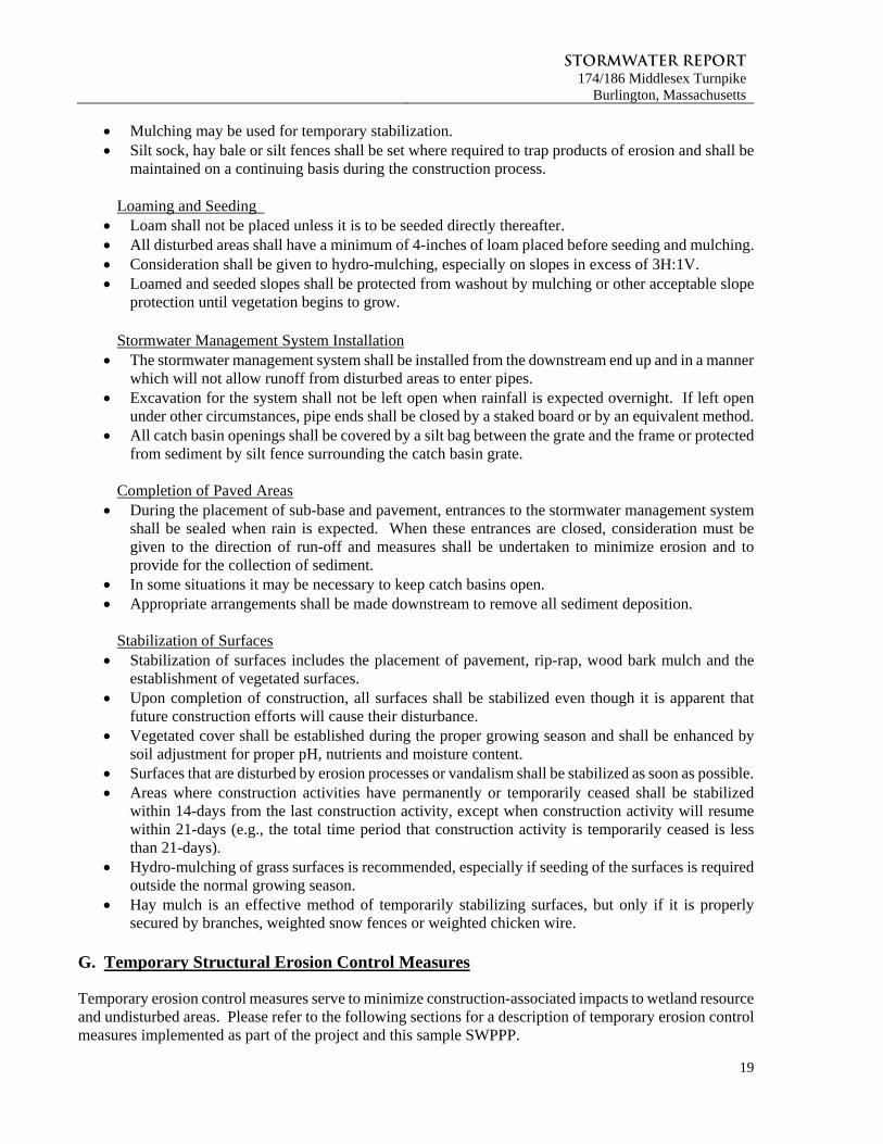
Silt Socks, Hay bales, and Silt Fencing
Siltation barriers composed of silt socks or double-staked hay bales and trenched silt fence will be installed as shown on the Site Plans. The siltation barriers will demarcate the limit of work, form a work envelope and provide additional assurance that construction equipment will not enter the adjacent wetlands or undisturbed portions of the site. All barriers will remain in place until disturbed areas are stabilized.
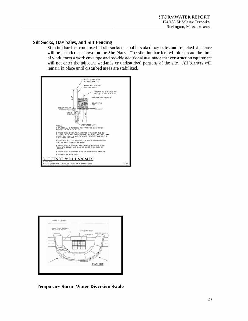
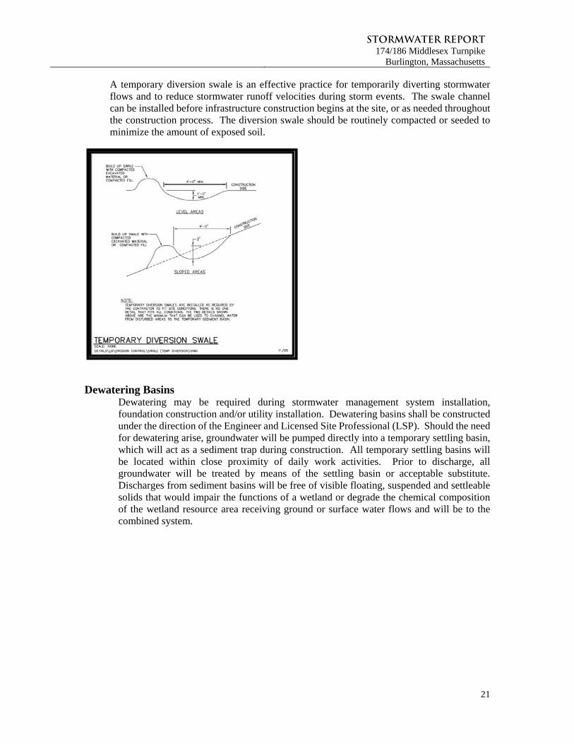
Temporary Storm Water Diversion Swale
Stormwater Report174/186 Middlesex Turnpike
Burlington, Massachusetts
21
A temporary diversion swale is an effective practice for temporarily diverting stormwater flows and to reduce stormwater runoff velocities during storm events. The swale channel can be installed before infrastructure construction begins at the site, or as needed throughout the construction process. The diversion swale should be routinely compacted or seeded to minimize the amount of exposed soil.
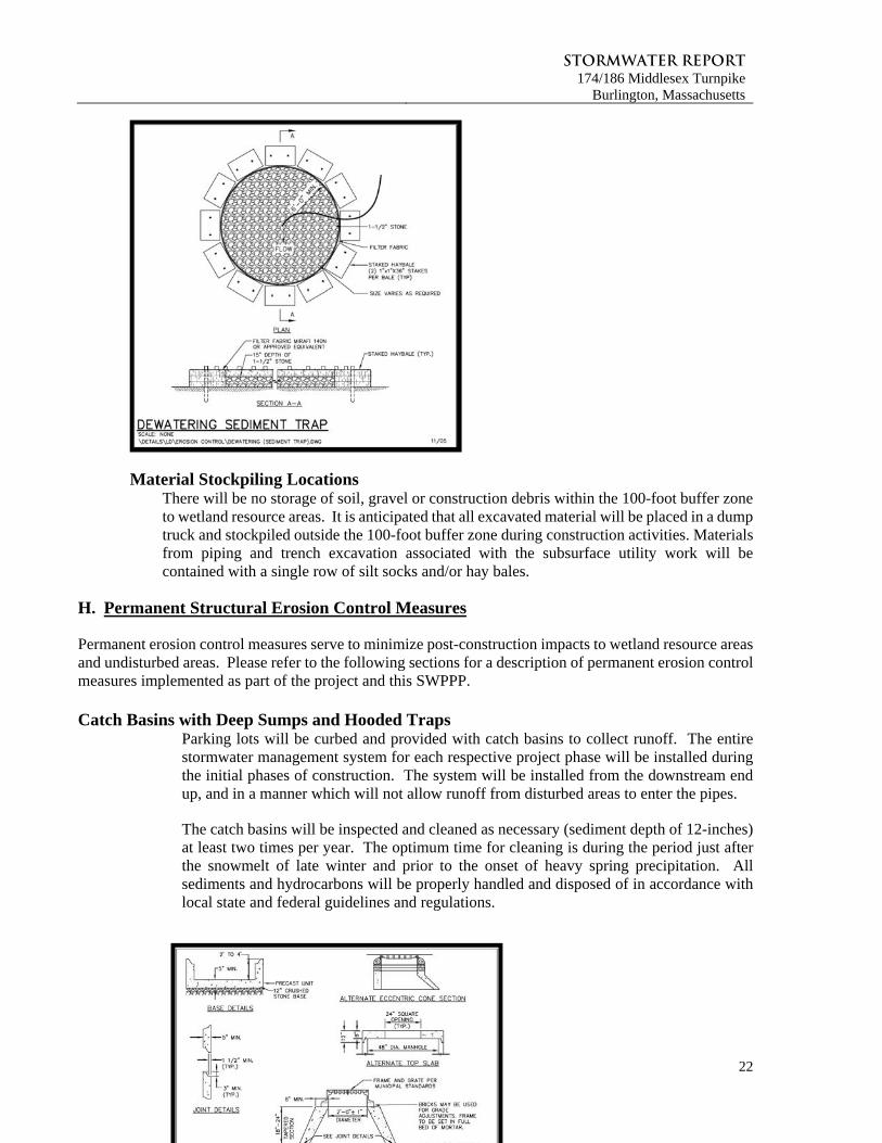
Dewatering Basins
Dewatering may be required during stormwater management system installation, foundation construction and/or utility installation. Dewatering basins shall be constructed under the direction of the Engineer and Licensed Site Professional (LSP). Should the need for dewatering arise, groundwater will be pumped directly into a temporary settling basin, which will act as a sediment trap during construction. All temporary settling basins will be located within close proximity of daily work activities. Prior to discharge, all groundwater will be treated by means of the settling basin or acceptable substitute. Discharges from sediment basins will be free of visible floating, suspended and settleable solids that would impair the functions of a wetland or degrade the chemical composition of the wetland resource area receiving ground or surface water flows and will be to the combined system.
Stormwater Report174/186 Middlesex Turnpike
Burlington, Massachusetts
22
Material Stockpiling Locations There will be no storage of soil, gravel or construction debris within the 100-foot buffer zone to wetland resource areas. It is anticipated that all excavated material will be placed in a dump truck and stockpiled outside the 100-foot buffer zone during construction activities. Materials from piping and trench excavation associated with the subsurface utility work will be contained with a single row of silt socks and/or hay bales.
H. Permanent Structural Erosion Control Measures
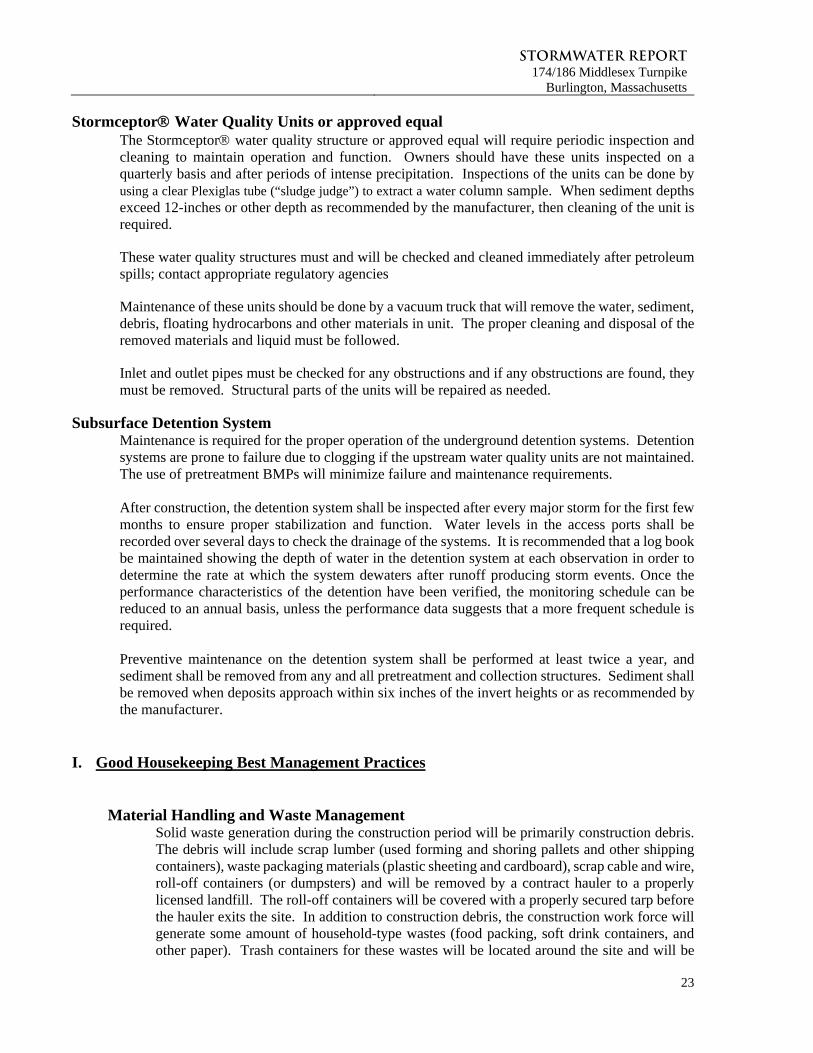
Permanent erosion control measures serve to minimize post-construction impacts to wetland resource areas and undisturbed areas. Please refer to the following sections for a description of permanent erosion control measures implemented as part of the project and this SWPPP. Catch Basins with Deep Sumps and Hooded Traps
Parking lots will be curbed and provided with catch basins to collect runoff. The entire stormwater management system for each respective project phase will be installed during the initial phases of construction. The system will be installed from the downstream end up, and in a manner which will not allow runoff from disturbed areas to enter the pipes.
The catch basins will be inspected and cleaned as necessary (sediment depth of 12-inches) at least two times per year. The optimum time for cleaning is during the period just after the snowmelt of late winter and prior to the onset of heavy spring precipitation. All sediments and hydrocarbons will be properly handled and disposed of in accordance with local state and federal guidelines and regulations.
Stormwater Report174/186 Middlesex Turnpike
Burlington, Massachusetts
23
Stormceptor Water Quality Units or approved equal The Stormceptor water quality structure or approved equal will require periodic inspection and cleaning to maintain operation and function. Owners should have these units inspected on a quarterly basis and after periods of intense precipitation. Inspections of the units can be done by using a clear Plexiglas tube (“sludge judge”) to extract a water column sample. When sediment depths exceed 12-inches or other depth as recommended by the manufacturer, then cleaning of the unit is required.
These water quality structures must and will be checked and cleaned immediately after petroleum spills; contact appropriate regulatory agencies
Maintenance of these units should be done by a vacuum truck that will remove the water, sediment, debris, floating hydrocarbons and other materials in unit. The proper cleaning and disposal of the removed materials and liquid must be followed.
Inlet and outlet pipes must be checked for any obstructions and if any obstructions are found, they must be removed. Structural parts of the units will be repaired as needed.
Subsurface Detention System
Maintenance is required for the proper operation of the underground detention systems. Detention systems are prone to failure due to clogging if the upstream water quality units are not maintained. The use of pretreatment BMPs will minimize failure and maintenance requirements.
After construction, the detention system shall be inspected after every major storm for the first few months to ensure proper stabilization and function. Water levels in the access ports shall be recorded over several days to check the drainage of the systems. It is recommended that a log book be maintained showing the depth of water in the detention system at each observation in order to determine the rate at which the system dewaters after runoff producing storm events. Once the performance characteristics of the detention have been verified, the monitoring schedule can be reduced to an annual basis, unless the performance data suggests that a more frequent schedule is required.
Preventive maintenance on the detention system shall be performed at least twice a year, and sediment shall be removed from any and all pretreatment and collection structures. Sediment shall be removed when deposits approach within six inches of the invert heights or as recommended by the manufacturer.
I. Good Housekeeping Best Management Practices
Material Handling and Waste Management
Solid waste generation during the construction period will be primarily construction debris. The debris will include scrap lumber (used forming and shoring pallets and other shipping containers), waste packaging materials (plastic sheeting and cardboard), scrap cable and wire, roll-off containers (or dumpsters) and will be removed by a contract hauler to a properly licensed landfill. The roll-off containers will be covered with a properly secured tarp before the hauler exits the site. In addition to construction debris, the construction work force will generate some amount of household-type wastes (food packing, soft drink containers, and other paper). Trash containers for these wastes will be located around the site and will be
Stormwater Report174/186 Middlesex Turnpike
Burlington, Massachusetts
24
emptied regularly so as to prevent wind-blown litter. This waste will also be removed by a contract hauler.
All hazardous waste material such as oil filters, petroleum products, and paint and equipment maintenance fluids will be stored in structurally sound and sealed shipping containers in the hazardous-materials storage area and segregated from other non-waste materials. Secondary containment will be provided for all materials in the hazardous materials storage area and will consist of commercially available spill pallets. Additionally, all hazardous materials will be disposed of in accordance with federal, state and municipal regulations.
Temporary sanitary facilities (portable toilets) will be provided at the site. The toilets will be located away from a concentrated flow path and traffic flow and will have collection pans underneath as secondary treatment. All sanitary waste will be collected from an approved party at a minimum of three times per week.
Building Material Staging Areas Construction equipment and maintenance materials will be stored at the combined staging area and materials storage areas. Silt fence will be installed around the perimeter to designate the staging and materials storage area. A watertight shipping container will be used to store hand tools, small parts and other construction materials.
Non-hazardous building materials such as packaging material (wood, plastic and glass) and construction scrap material (brick, wood, steel, metal scraps, and pine cuttings) will be stored in a separate covered storage facility adjacent to other stored materials. All hazardous-waste materials such as oil filters, petroleum products, and paint and equipment maintenance fluids will be stored in structurally sound and sealed containers under cover within the hazardous materials storage area.
Large items such as framing materials and stockpiled lumber will be stored in the open storage area. Such materials will be elevated on wood blocks to minimize contact with runoff.
The combined storage areas are expected to remain clean, well-organized and equipped with ample cleaning supplies as appropriate for the materials being stored. Perimeter controls such as containment structures, covers and liners will be repaired or replaced as necessary to maintain proper function.
Designated Washout Areas Designated temporary, below-ground concrete washout areas will be constructed, as required, to minimize the pollution potential associated with concrete, paint, stucco, mixers etc. Signs will, if required, be posted marking the location of the washout area to ensure that concrete equipment operators use the proper facility. Concrete pours will not be conducted during or before an anticipated precipitation event. All excess concrete and concrete washout slurries from the concrete mixer trucks and chutes will be discharged to the washout area or hauled off-site for disposal.
Equipment/Vehicle Maintenance and Fueling Areas Several types of vehicles and equipment will be used on-site throughout the project including graders, scrapers, excavators, loaders, paving equipment, rollers, trucks and trailers, backhoes and forklifts. All major equipment/vehicle fueling and maintenance will be
Stormwater Report174/186 Middlesex Turnpike
Burlington, Massachusetts
25
performed off-site. A small, 20-gallon pickup bed fuel tank will be kept on-site in the combined staging area. When vehicle fueling must occur on-site, the fueling activity will occur in the staging area. Only minor equipment maintenance will occur on-site. All equipment fluids generated from maintenance activities will be disposed of into designated drums stored on spill pallets. Absorbent, spill-cleanup materials and spill kits will be available at the combined staging and materials storage area. Drip pans will be placed under all equipment receiving maintenance and vehicles and equipment parked overnight.
Equipment/Vehicle Wash down Area All equipment and vehicle washing will be performed off-site.
Spill Prevention Plan A spill containment kit will be kept on-site in the Contractor’s trailer and/or the designated staging area throughout the duration of construction. Should there be an accidental release of petroleum product into a wetland or within 100-feet of a wetland, the appropriate agencies will be immediately notified.
J. Inspections
Maintenance of existing and proposed BMP’s to address stormwater management facilities during construction is an on-going process. Inspections should be conducted a minimum of once weekly and after storms larger than 0.5 inches. The purpose of the inspections is to observe all sources of stormwater or non-stormwater discharge as identified in the SWPPP as well as the status of the receiving waters and fulfill the requirements of the Order of Conditions. The following sections describe the appropriate inspection measures to adequately implement the project’s SWPPP. A blank inspection form is provided at the end of this section. Completed inspection forms are to be maintained on site.
i. Inspection Personnel
The owner’s appointed representative will be responsible for performing regular inspections of erosion controls and ordering repairs as necessary.
ii. Inspection Frequency
Inspections will be performed by qualified personnel once every 7 days and after storms larger than 0.5 inches in accordance with the CGP and as required by the OOC. The inspections must be documented on the inspection form provided at the end of this section, and completed forms will be provided to the on-site supervisor and maintained at the Owner’s office throughout the entire duration of construction.
iii. Inspection Reporting
Each inspection report will summarize the scope of the inspection, name(s) and qualifications of personnel making the inspection, and major observations relating to the implementation of the SWPPP, including compliance and non-compliance items. Completed inspection reports will remain with the completed SWPPP on site.
Stormwater Report174/186 Middlesex Turnpike
Burlington, Massachusetts
26
K. Amendment Requirements
The final SWPPP is intended to be a working document that is utilized regularly on the construction site, and provides guidance to the Contractor. It must reflect changes made to the originally proposed plan and will be updated to include project specific activities and ensure that they are in compliance with the NPDES General Permit and state and local laws and regulations. It should be amended whenever there is a change in design, construction, operation or maintenance that affects discharge of pollutants. The following items should be addressed should an amendment to the SWPPP occur:
Dates of certain construction activities such as major grading activities, clearing and initiation of and completion of stabilization measures should be recorded.
Future amendments to the SWPPP will be recorded as required. As this SWPPP is amended, all amendments will be kept on site and made part of the SWPPP.
Upon completion of site stabilization (completed as designed and/or 70% background vegetative cover), it can be documented and marked on the plans. Inspections are no longer required at this time.
Inspections often identify areas not included in the original SWPPP, which will require the SWPPP to be amended. These updates should be made within seven days of being recognized by the inspector.
Stormwater Report174/186 Middlesex Turnpike
Burlington, Massachusetts
27
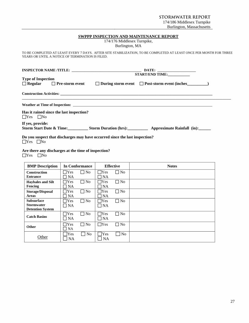
SWPPP INSPECTION AND MAINTENANCE REPORT 174/176 Middlesex Turnpike,
Burlington, MA
TO BE COMPLETED AT LEAST EVERY 7 DAYS. AFTER SITE STABILIZATION, TO BE COMPLETED AT LEAST ONCE PER MONTH FOR THREE YEARS OR UNTIL A NOTICE OF TERMINATION IS FILED.
INSPECTOR NAME /TITLE: ______________________________________ DATE: _____________________ START/END TIME:____________ Type of Inspection
Regular Pre-storm event During storm event Post-storm event (inches__________)
Construction Activities: ___________________________________________________________________________________ __________________________________________________________________________________________________________________
Weather at Time of Inspection: ____________________________________________________________________________
Has it rained since the last inspection? Yes No
If yes, provide: Storm Start Date & Time:__________ Storm Duration (hrs):__________ Approximate Rainfall (in):______ Do you suspect that discharges may have occurred since the last inspection?
Yes No Are there any discharges at the time of inspection?
Yes No
BMP Description In Conformance Effective Notes
Construction Entrance
Yes No NA
Yes No NA
Haybales and Silt Fencing
Yes No NA
Yes No NA
Storage/Disposal Areas
Yes No NA
Yes No NA
Subsurface Stormwater Detention System
Yes No NA
Yes No NA
Catch Basins Yes No NA
Yes No NA
Other Yes No NA
Yes No
Other Yes No NA
Yes No NA
Stormwater Report174/186 Middlesex Turnpike
Burlington, Massachusetts
28
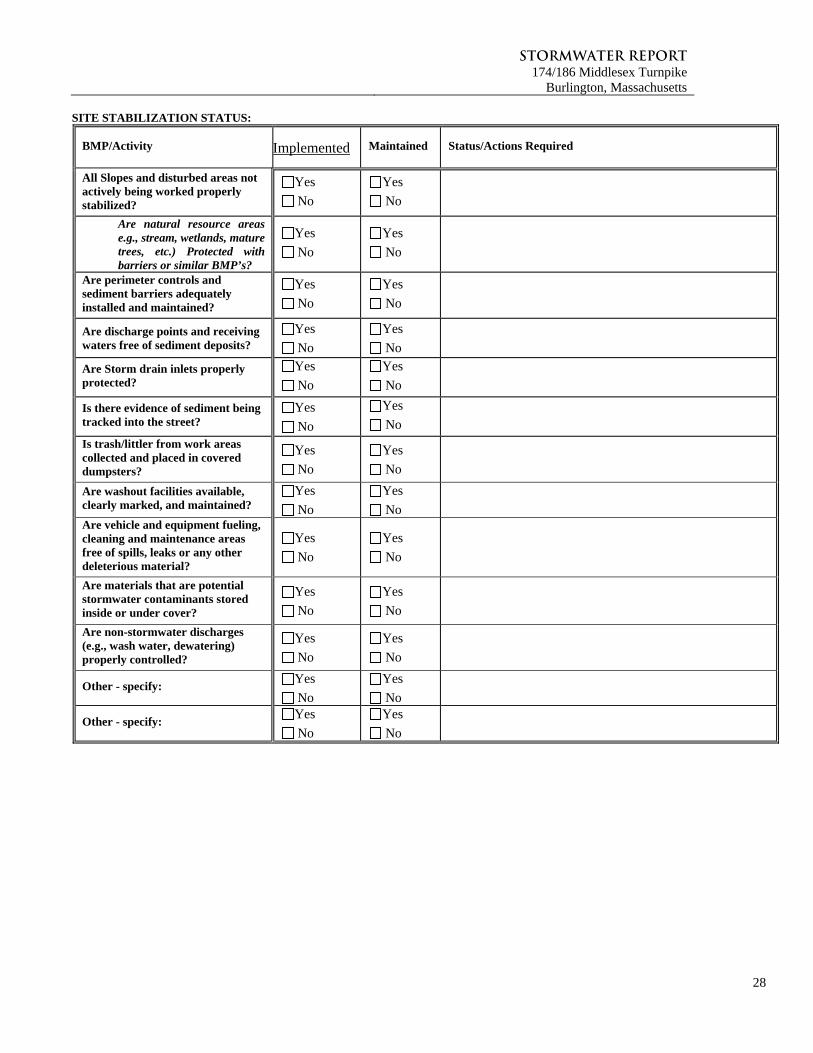
SITE STABILIZATION STATUS:
BMP/Activity Implemented Maintained Status/Actions Required
All Slopes and disturbed areas not actively being worked properly stabilized?
Yes
No
Yes
No
Are natural resource areas e.g., stream, wetlands, mature trees, etc.) Protected with barriers or similar BMP’s?
Yes
No
Yes
No
Are perimeter controls and sediment barriers adequately installed and maintained?
Yes
No
Yes
No
Are discharge points and receiving waters free of sediment deposits?
Yes
No
Yes
No
Are Storm drain inlets properly protected?
Yes
No
Yes
No
Is there evidence of sediment being tracked into the street?
Yes
No Yes
No
Is trash/littler from work areas collected and placed in covered dumpsters?
Yes
No
Yes
No
Are washout facilities available, clearly marked, and maintained?
Yes
No
Yes
No
Are vehicle and equipment fueling, cleaning and maintenance areas free of spills, leaks or any other deleterious material?
Yes
No
Yes
No
Are materials that are potential stormwater contaminants stored inside or under cover?
Yes
No
Yes
No
Are non-stormwater discharges (e.g., wash water, dewatering) properly controlled?
Yes
No
Yes
No
Other - specify: Yes
No
Yes
No
Other - specify: Yes
No
Yes
No
Stormwater Report174/186 Middlesex Turnpike
Burlington, Massachusetts
29
ADDITIONAL OBSERVATIONS: NEXT INSPECTION TO BE PERFORMED BY: ON OR BEFORE:
Certification statement: “I certify under penalty of law that this document and all attachments were prepared under my direction or supervision in accordance with a system designed to assure that qualified personnel properly gathered and evaluated the information submitted. Based on my inquiry of the person or persons who manage the system, or those persons directly responsible for gathering the information, the information submitted is, to the best of my knowledge and belief, true, accurate, and complete. I am aware that there are significant penalties for submitting false information, including the possibility of fine and imprisonment for knowing violations.” Print name: _________________________________________________________________________ Signature: ______________________________________ Date:__________________________
Stormwater Report174/186 Middlesex Turnpike
Burlington, Massachusetts
SECTION 4.0
PEAK RUNOFF RATE CALCULATIONS
4.01 EXISTING CONDITIONS WATERSHED ANALYSIS PLAN 4.02 EXISTING CONDITIONS HYDROCAD PRINTOUTS 4.03 PROPOSED CONDITIONS WATERSHED ANALYSIS PLAN 4.04 PROPOSED CONDITIONS HYDROCAD PRINTOUTS
Stormwater Report174/186 Middlesex Turnpike
Burlington, Massachusetts
4.01
EXISTING CONDITIONS WATERSHED ANALYSIS PLAN
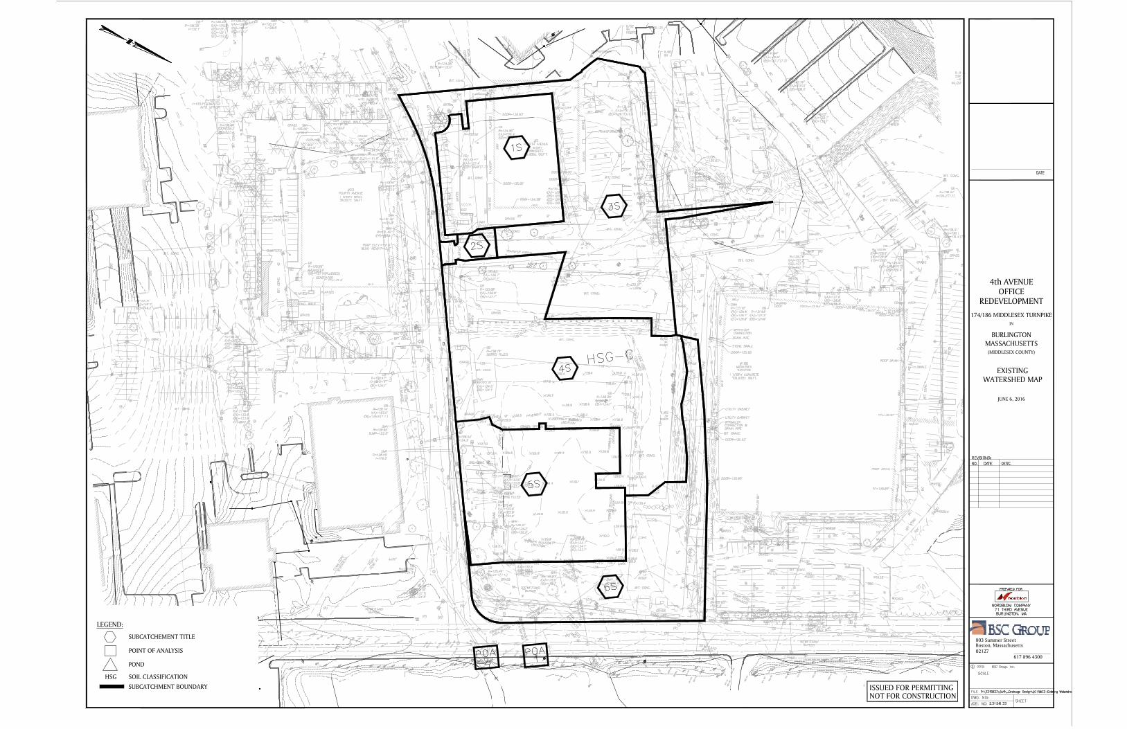
EXISTINGWATERSHED MAP
ISSUED FOR PERMITTINGNOT FOR CONSTRUCTION
617 896 430002127Boston, Massachusetts803 Summer Street
IN
4th AVENUEOFFICE
174/186 MIDDLESEX TURNPIKE
BURLINGTONMASSACHUSETTS
(MIDDLESEX COUNTY)
REDEVELOPMENT
JUNE 6, 2016
LEGEND:
SUBCATCHEMENT TITLE
POINT OF ANALYSIS
POND
HSG SOIL CLASSIFICATION
SUBCATCHMENT BOUNDARY
Stormwater Report174/186 Middlesex Turnpike
Burlington, Massachusetts
4.02
EXISTING CONDITIONS HYDROCAD PRINTOUTS
1S
(new Subcat)
2S
(new Subcat)
3S
(new Subcat)
4S
(new Subcat)
5S
(new Subcat)
6S
(new Subcat)
POA-1
4th Ave Drainage
POA-2
Middlesex Turnpike Drainage
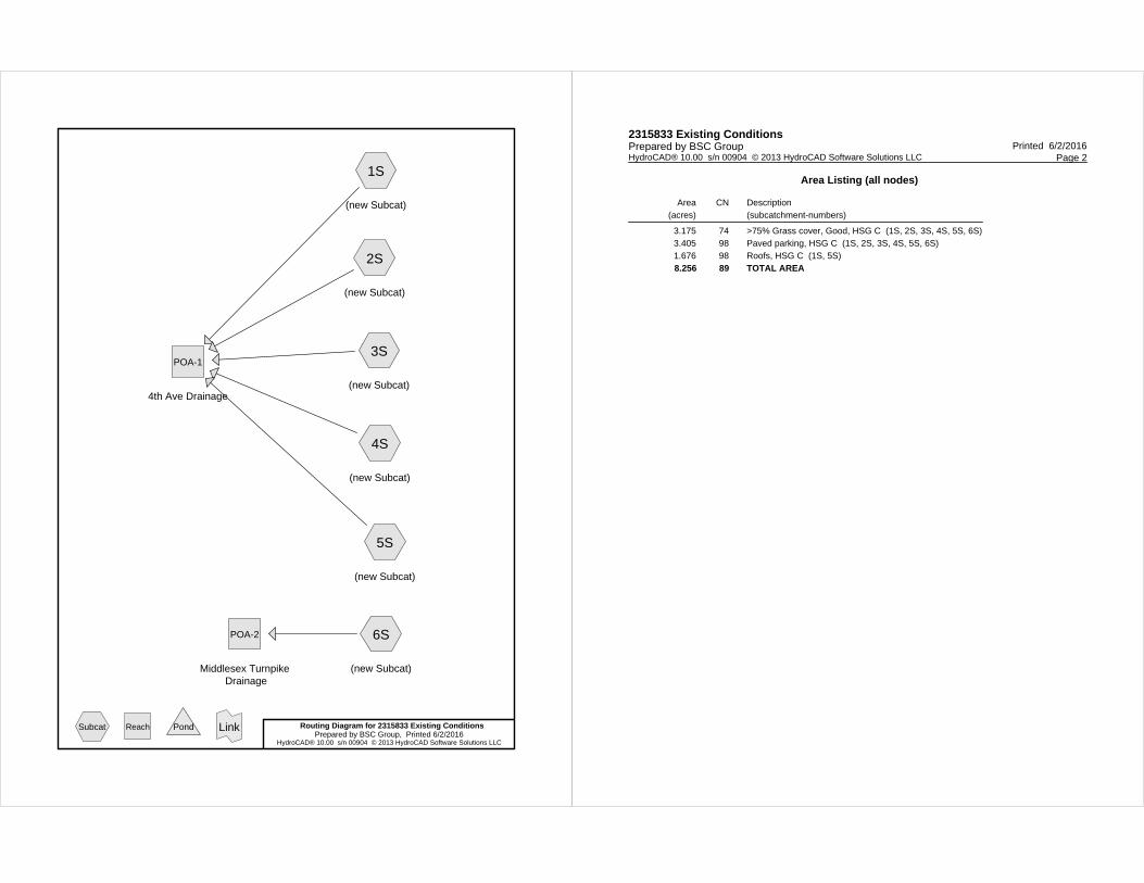
Routing Diagram for 2315833 Existing ConditionsPrepared by BSC Group, Printed 6/2/2016
HydroCAD® 10.00 s/n 00904 © 2013 HydroCAD Software Solutions LLC
Subcat Reach Pond Link
2315833 Existing Conditions Printed 6/2/2016Prepared by BSC Group
Page 2HydroCAD® 10.00 s/n 00904 © 2013 HydroCAD Software Solutions LLC
Area Listing (all nodes)
Area(acres)
CN Description(subcatchment-numbers)
3.175 74 >75% Grass cover, Good, HSG C (1S, 2S, 3S, 4S, 5S, 6S)3.405 98 Paved parking, HSG C (1S, 2S, 3S, 4S, 5S, 6S)1.676 98 Roofs, HSG C (1S, 5S)
8.256 89 TOTAL AREA
2315833 Existing Conditions Printed 6/2/2016Prepared by BSC Group
Page 3HydroCAD® 10.00 s/n 00904 © 2013 HydroCAD Software Solutions LLC
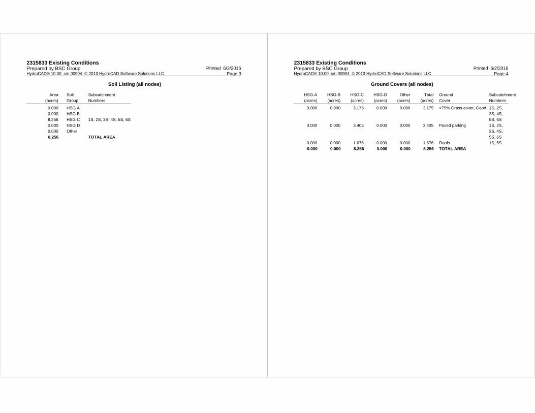
Soil Listing (all nodes)
Area(acres)
SoilGroup
SubcatchmentNumbers
0.000 HSG A0.000 HSG B8.256 HSG C 1S, 2S, 3S, 4S, 5S, 6S0.000 HSG D0.000 Other
8.256 TOTAL AREA
2315833 Existing Conditions Printed 6/2/2016Prepared by BSC Group
Page 4HydroCAD® 10.00 s/n 00904 © 2013 HydroCAD Software Solutions LLC
Ground Covers (all nodes)
HSG-A(acres)
HSG-B(acres)
HSG-C(acres)
HSG-D(acres)
Other(acres)
Total(acres)
GroundCover
SubcatchmentNumbers
0.000 0.000 3.175 0.000 0.000 3.175 >75% Grass cover, Good 1S, 2S, 3S, 4S, 5S, 6S
0.000 0.000 3.405 0.000 0.000 3.405 Paved parking 1S, 2S, 3S, 4S, 5S, 6S
0.000 0.000 1.676 0.000 0.000 1.676 Roofs 1S, 5S
0.000 0.000 8.256 0.000 0.000 8.256 TOTAL AREA

Type III 24-hr 2-yr Rainfall=3.10"2315833 Existing Conditions Printed 6/2/2016Prepared by BSC Group
Page 5HydroCAD® 10.00 s/n 00904 © 2013 HydroCAD Software Solutions LLC
Time span=0.00-24.00 hrs, dt=0.01 hrs, 2401 pointsRunoff by SCS TR-20 method, UH=SCS, Weighted-CN
Reach routing by Stor-Ind+Trans method - Pond routing by Stor-Ind method
Runoff Area=40,489 sf 96.28% Impervious Runoff Depth>2.76"Subcatchment 1S: (new Subcat) Tc=6.0 min CN=97 Runoff=2.75 cfs 0.213 af
Runoff Area=10,349 sf 14.97% Impervious Runoff Depth>1.20"Subcatchment 2S: (new Subcat) Tc=6.0 min CN=78 Runoff=0.33 cfs 0.024 af
Runoff Area=89,697 sf 50.63% Impervious Runoff Depth>1.75"Subcatchment 3S: (new Subcat) Tc=6.0 min CN=86 Runoff=4.22 cfs 0.300 af
Runoff Area=98,323 sf 70.90% Impervious Runoff Depth>2.16"Subcatchment 4S: (new Subcat) Tc=6.0 min CN=91 Runoff=5.64 cfs 0.407 af
Runoff Area=58,708 sf 75.98% Impervious Runoff Depth>2.25"Subcatchment 5S: (new Subcat) Tc=6.0 min CN=92 Runoff=3.49 cfs 0.253 af
Runoff Area=62,055 sf 33.94% Impervious Runoff Depth>1.46"Subcatchment 6S: (new Subcat) Tc=6.0 min CN=82 Runoff=2.42 cfs 0.173 af
Inflow=16.43 cfs 1.197 afReach POA-1: 4th Ave Drainage Outflow=16.43 cfs 1.197 af
Inflow=2.42 cfs 0.173 afReach POA-2: Middlesex Turnpike Drainage Outflow=2.42 cfs 0.173 af
Total Runoff Area = 8.256 ac Runoff Volume = 1.370 af Average Runoff Depth = 1.99"38.46% Pervious = 3.175 ac 61.54% Impervious = 5.081 ac
Type III 24-hr 2-yr Rainfall=3.10"2315833 Existing Conditions Printed 6/2/2016Prepared by BSC Group
Page 6HydroCAD® 10.00 s/n 00904 © 2013 HydroCAD Software Solutions LLC
Summary for Subcatchment 1S: (new Subcat)
Runoff = 2.75 cfs @ 12.08 hrs, Volume= 0.213 af, Depth> 2.76"
Runoff by SCS TR-20 method, UH=SCS, Weighted-CN, Time Span= 0.00-24.00 hrs, dt= 0.01 hrsType III 24-hr 2-yr Rainfall=3.10"
Area (sf) CN Description1,508 74 >75% Grass cover, Good, HSG C
30,379 98 Roofs, HSG C8,602 98 Paved parking, HSG C
40,489 97 Weighted Average1,508 3.72% Pervious Area
38,981 96.28% Impervious Area
Tc Length Slope Velocity Capacity Description(min) (feet) (ft/ft) (ft/sec) (cfs)
6.0 Direct Entry, Minimum
Summary for Subcatchment 2S: (new Subcat)
Runoff = 0.33 cfs @ 12.09 hrs, Volume= 0.024 af, Depth> 1.20"
Runoff by SCS TR-20 method, UH=SCS, Weighted-CN, Time Span= 0.00-24.00 hrs, dt= 0.01 hrsType III 24-hr 2-yr Rainfall=3.10"
Area (sf) CN Description1,549 98 Paved parking, HSG C8,800 74 >75% Grass cover, Good, HSG C
10,349 78 Weighted Average8,800 85.03% Pervious Area1,549 14.97% Impervious Area
Tc Length Slope Velocity Capacity Description(min) (feet) (ft/ft) (ft/sec) (cfs)
6.0 Direct Entry, Minimum
Summary for Subcatchment 3S: (new Subcat)
Runoff = 4.22 cfs @ 12.09 hrs, Volume= 0.300 af, Depth> 1.75"
Runoff by SCS TR-20 method, UH=SCS, Weighted-CN, Time Span= 0.00-24.00 hrs, dt= 0.01 hrsType III 24-hr 2-yr Rainfall=3.10"
Area (sf) CN Description44,286 74 >75% Grass cover, Good, HSG C45,411 98 Paved parking, HSG C89,697 86 Weighted Average44,286 49.37% Pervious Area45,411 50.63% Impervious Area

Type III 24-hr 2-yr Rainfall=3.10"2315833 Existing Conditions Printed 6/2/2016Prepared by BSC Group
Page 7HydroCAD® 10.00 s/n 00904 © 2013 HydroCAD Software Solutions LLC
Tc Length Slope Velocity Capacity Description(min) (feet) (ft/ft) (ft/sec) (cfs)
6.0 Direct Entry, Minimum
Summary for Subcatchment 4S: (new Subcat)
Runoff = 5.64 cfs @ 12.09 hrs, Volume= 0.407 af, Depth> 2.16"
Runoff by SCS TR-20 method, UH=SCS, Weighted-CN, Time Span= 0.00-24.00 hrs, dt= 0.01 hrsType III 24-hr 2-yr Rainfall=3.10"
Area (sf) CN Description28,612 74 >75% Grass cover, Good, HSG C69,711 98 Paved parking, HSG C98,323 91 Weighted Average28,612 29.10% Pervious Area69,711 70.90% Impervious Area
Tc Length Slope Velocity Capacity Description(min) (feet) (ft/ft) (ft/sec) (cfs)
6.0 Direct Entry, Minimum
Summary for Subcatchment 5S: (new Subcat)
Runoff = 3.49 cfs @ 12.09 hrs, Volume= 0.253 af, Depth> 2.25"
Runoff by SCS TR-20 method, UH=SCS, Weighted-CN, Time Span= 0.00-24.00 hrs, dt= 0.01 hrsType III 24-hr 2-yr Rainfall=3.10"
Area (sf) CN Description42,614 98 Roofs, HSG C
1,992 98 Paved parking, HSG C14,102 74 >75% Grass cover, Good, HSG C58,708 92 Weighted Average14,102 24.02% Pervious Area44,606 75.98% Impervious Area
Tc Length Slope Velocity Capacity Description(min) (feet) (ft/ft) (ft/sec) (cfs)
6.0 Direct Entry, Minimum
Summary for Subcatchment 6S: (new Subcat)
Runoff = 2.42 cfs @ 12.09 hrs, Volume= 0.173 af, Depth> 1.46"
Runoff by SCS TR-20 method, UH=SCS, Weighted-CN, Time Span= 0.00-24.00 hrs, dt= 0.01 hrsType III 24-hr 2-yr Rainfall=3.10"
Type III 24-hr 2-yr Rainfall=3.10"2315833 Existing Conditions Printed 6/2/2016Prepared by BSC Group
Page 8HydroCAD® 10.00 s/n 00904 © 2013 HydroCAD Software Solutions LLC
Area (sf) CN Description21,062 98 Paved parking, HSG C40,993 74 >75% Grass cover, Good, HSG C62,055 82 Weighted Average40,993 66.06% Pervious Area21,062 33.94% Impervious Area
Tc Length Slope Velocity Capacity Description(min) (feet) (ft/ft) (ft/sec) (cfs)
6.0 Direct Entry, Minimum
Summary for Reach POA-1: 4th Ave Drainage
Inflow Area = 6.831 ac, 67.30% Impervious, Inflow Depth > 2.10" for 2-yr eventInflow = 16.43 cfs @ 12.09 hrs, Volume= 1.197 afOutflow = 16.43 cfs @ 12.09 hrs, Volume= 1.197 af, Atten= 0%, Lag= 0.0 min
Routing by Stor-Ind+Trans method, Time Span= 0.00-24.00 hrs, dt= 0.01 hrs
Summary for Reach POA-2: Middlesex Turnpike Drainage
Inflow Area = 1.425 ac, 33.94% Impervious, Inflow Depth > 1.46" for 2-yr eventInflow = 2.42 cfs @ 12.09 hrs, Volume= 0.173 afOutflow = 2.42 cfs @ 12.09 hrs, Volume= 0.173 af, Atten= 0%, Lag= 0.0 min
Routing by Stor-Ind+Trans method, Time Span= 0.00-24.00 hrs, dt= 0.01 hrs

Type III 24-hr 10-yr Rainfall=4.50"2315833 Existing Conditions Printed 6/2/2016Prepared by BSC Group
Page 9HydroCAD® 10.00 s/n 00904 © 2013 HydroCAD Software Solutions LLC
Time span=0.00-24.00 hrs, dt=0.01 hrs, 2401 pointsRunoff by SCS TR-20 method, UH=SCS, Weighted-CN
Reach routing by Stor-Ind+Trans method - Pond routing by Stor-Ind method
Runoff Area=40,489 sf 96.28% Impervious Runoff Depth>4.15"Subcatchment 1S: (new Subcat) Tc=6.0 min CN=97 Runoff=4.05 cfs 0.321 af
Runoff Area=10,349 sf 14.97% Impervious Runoff Depth>2.29"Subcatchment 2S: (new Subcat) Tc=6.0 min CN=78 Runoff=0.64 cfs 0.045 af
Runoff Area=89,697 sf 50.63% Impervious Runoff Depth>3.00"Subcatchment 3S: (new Subcat) Tc=6.0 min CN=86 Runoff=7.19 cfs 0.515 af
Runoff Area=98,323 sf 70.90% Impervious Runoff Depth>3.49"Subcatchment 4S: (new Subcat) Tc=6.0 min CN=91 Runoff=8.92 cfs 0.657 af
Runoff Area=58,708 sf 75.98% Impervious Runoff Depth>3.60"Subcatchment 5S: (new Subcat) Tc=6.0 min CN=92 Runoff=5.44 cfs 0.404 af
Runoff Area=62,055 sf 33.94% Impervious Runoff Depth>2.63"Subcatchment 6S: (new Subcat) Tc=6.0 min CN=82 Runoff=4.40 cfs 0.313 af
Inflow=26.24 cfs 1.943 afReach POA-1: 4th Ave Drainage Outflow=26.24 cfs 1.943 af
Inflow=4.40 cfs 0.313 afReach POA-2: Middlesex Turnpike Drainage Outflow=4.40 cfs 0.313 af
Total Runoff Area = 8.256 ac Runoff Volume = 2.255 af Average Runoff Depth = 3.28"38.46% Pervious = 3.175 ac 61.54% Impervious = 5.081 ac
Type III 24-hr 10-yr Rainfall=4.50"2315833 Existing Conditions Printed 6/2/2016Prepared by BSC Group
Page 10HydroCAD® 10.00 s/n 00904 © 2013 HydroCAD Software Solutions LLC
Summary for Subcatchment 1S: (new Subcat)
Runoff = 4.05 cfs @ 12.08 hrs, Volume= 0.321 af, Depth> 4.15"
Runoff by SCS TR-20 method, UH=SCS, Weighted-CN, Time Span= 0.00-24.00 hrs, dt= 0.01 hrsType III 24-hr 10-yr Rainfall=4.50"
Area (sf) CN Description1,508 74 >75% Grass cover, Good, HSG C
30,379 98 Roofs, HSG C8,602 98 Paved parking, HSG C
40,489 97 Weighted Average1,508 3.72% Pervious Area
38,981 96.28% Impervious Area
Tc Length Slope Velocity Capacity Description(min) (feet) (ft/ft) (ft/sec) (cfs)
6.0 Direct Entry, Minimum
Summary for Subcatchment 2S: (new Subcat)
Runoff = 0.64 cfs @ 12.09 hrs, Volume= 0.045 af, Depth> 2.29"
Runoff by SCS TR-20 method, UH=SCS, Weighted-CN, Time Span= 0.00-24.00 hrs, dt= 0.01 hrsType III 24-hr 10-yr Rainfall=4.50"
Area (sf) CN Description1,549 98 Paved parking, HSG C8,800 74 >75% Grass cover, Good, HSG C
10,349 78 Weighted Average8,800 85.03% Pervious Area1,549 14.97% Impervious Area
Tc Length Slope Velocity Capacity Description(min) (feet) (ft/ft) (ft/sec) (cfs)
6.0 Direct Entry, Minimum
Summary for Subcatchment 3S: (new Subcat)
Runoff = 7.19 cfs @ 12.09 hrs, Volume= 0.515 af, Depth> 3.00"
Runoff by SCS TR-20 method, UH=SCS, Weighted-CN, Time Span= 0.00-24.00 hrs, dt= 0.01 hrsType III 24-hr 10-yr Rainfall=4.50"
Area (sf) CN Description44,286 74 >75% Grass cover, Good, HSG C45,411 98 Paved parking, HSG C89,697 86 Weighted Average44,286 49.37% Pervious Area45,411 50.63% Impervious Area

Type III 24-hr 10-yr Rainfall=4.50"2315833 Existing Conditions Printed 6/2/2016Prepared by BSC Group
Page 11HydroCAD® 10.00 s/n 00904 © 2013 HydroCAD Software Solutions LLC
Tc Length Slope Velocity Capacity Description(min) (feet) (ft/ft) (ft/sec) (cfs)
6.0 Direct Entry, Minimum
Summary for Subcatchment 4S: (new Subcat)
Runoff = 8.92 cfs @ 12.09 hrs, Volume= 0.657 af, Depth> 3.49"
Runoff by SCS TR-20 method, UH=SCS, Weighted-CN, Time Span= 0.00-24.00 hrs, dt= 0.01 hrsType III 24-hr 10-yr Rainfall=4.50"
Area (sf) CN Description28,612 74 >75% Grass cover, Good, HSG C69,711 98 Paved parking, HSG C98,323 91 Weighted Average28,612 29.10% Pervious Area69,711 70.90% Impervious Area
Tc Length Slope Velocity Capacity Description(min) (feet) (ft/ft) (ft/sec) (cfs)
6.0 Direct Entry, Minimum
Summary for Subcatchment 5S: (new Subcat)
Runoff = 5.44 cfs @ 12.08 hrs, Volume= 0.404 af, Depth> 3.60"
Runoff by SCS TR-20 method, UH=SCS, Weighted-CN, Time Span= 0.00-24.00 hrs, dt= 0.01 hrsType III 24-hr 10-yr Rainfall=4.50"
Area (sf) CN Description42,614 98 Roofs, HSG C
1,992 98 Paved parking, HSG C14,102 74 >75% Grass cover, Good, HSG C58,708 92 Weighted Average14,102 24.02% Pervious Area44,606 75.98% Impervious Area
Tc Length Slope Velocity Capacity Description(min) (feet) (ft/ft) (ft/sec) (cfs)
6.0 Direct Entry, Minimum
Summary for Subcatchment 6S: (new Subcat)
Runoff = 4.40 cfs @ 12.09 hrs, Volume= 0.313 af, Depth> 2.63"
Runoff by SCS TR-20 method, UH=SCS, Weighted-CN, Time Span= 0.00-24.00 hrs, dt= 0.01 hrsType III 24-hr 10-yr Rainfall=4.50"
Type III 24-hr 10-yr Rainfall=4.50"2315833 Existing Conditions Printed 6/2/2016Prepared by BSC Group
Page 12HydroCAD® 10.00 s/n 00904 © 2013 HydroCAD Software Solutions LLC
Area (sf) CN Description21,062 98 Paved parking, HSG C40,993 74 >75% Grass cover, Good, HSG C62,055 82 Weighted Average40,993 66.06% Pervious Area21,062 33.94% Impervious Area
Tc Length Slope Velocity Capacity Description(min) (feet) (ft/ft) (ft/sec) (cfs)
6.0 Direct Entry, Minimum
Summary for Reach POA-1: 4th Ave Drainage
Inflow Area = 6.831 ac, 67.30% Impervious, Inflow Depth > 3.41" for 10-yr eventInflow = 26.24 cfs @ 12.09 hrs, Volume= 1.943 afOutflow = 26.24 cfs @ 12.09 hrs, Volume= 1.943 af, Atten= 0%, Lag= 0.0 min
Routing by Stor-Ind+Trans method, Time Span= 0.00-24.00 hrs, dt= 0.01 hrs
Summary for Reach POA-2: Middlesex Turnpike Drainage
Inflow Area = 1.425 ac, 33.94% Impervious, Inflow Depth > 2.63" for 10-yr eventInflow = 4.40 cfs @ 12.09 hrs, Volume= 0.313 afOutflow = 4.40 cfs @ 12.09 hrs, Volume= 0.313 af, Atten= 0%, Lag= 0.0 min
Routing by Stor-Ind+Trans method, Time Span= 0.00-24.00 hrs, dt= 0.01 hrs

Type III 24-hr 25-yr Rainfall=5.40"2315833 Existing Conditions Printed 6/2/2016Prepared by BSC Group
Page 13HydroCAD® 10.00 s/n 00904 © 2013 HydroCAD Software Solutions LLC
Time span=0.00-24.00 hrs, dt=0.01 hrs, 2401 pointsRunoff by SCS TR-20 method, UH=SCS, Weighted-CN
Reach routing by Stor-Ind+Trans method - Pond routing by Stor-Ind method
Runoff Area=40,489 sf 96.28% Impervious Runoff Depth>5.04"Subcatchment 1S: (new Subcat) Tc=6.0 min CN=97 Runoff=4.88 cfs 0.391 af
Runoff Area=10,349 sf 14.97% Impervious Runoff Depth>3.05"Subcatchment 2S: (new Subcat) Tc=6.0 min CN=78 Runoff=0.85 cfs 0.060 af
Runoff Area=89,697 sf 50.63% Impervious Runoff Depth>3.84"Subcatchment 3S: (new Subcat) Tc=6.0 min CN=86 Runoff=9.11 cfs 0.659 af
Runoff Area=98,323 sf 70.90% Impervious Runoff Depth>4.37"Subcatchment 4S: (new Subcat) Tc=6.0 min CN=91 Runoff=11.02 cfs 0.821 af
Runoff Area=58,708 sf 75.98% Impervious Runoff Depth>4.48"Subcatchment 5S: (new Subcat) Tc=6.0 min CN=92 Runoff=6.68 cfs 0.503 af
Runoff Area=62,055 sf 33.94% Impervious Runoff Depth>3.44"Subcatchment 6S: (new Subcat) Tc=6.0 min CN=82 Runoff=5.72 cfs 0.408 af
Inflow=32.55 cfs 2.434 afReach POA-1: 4th Ave Drainage Outflow=32.55 cfs 2.434 af
Inflow=5.72 cfs 0.408 afReach POA-2: Middlesex Turnpike Drainage Outflow=5.72 cfs 0.408 af
Total Runoff Area = 8.256 ac Runoff Volume = 2.842 af Average Runoff Depth = 4.13"38.46% Pervious = 3.175 ac 61.54% Impervious = 5.081 ac
Type III 24-hr 25-yr Rainfall=5.40"2315833 Existing Conditions Printed 6/2/2016Prepared by BSC Group
Page 14HydroCAD® 10.00 s/n 00904 © 2013 HydroCAD Software Solutions LLC
Summary for Subcatchment 1S: (new Subcat)
Runoff = 4.88 cfs @ 12.08 hrs, Volume= 0.391 af, Depth> 5.04"
Runoff by SCS TR-20 method, UH=SCS, Weighted-CN, Time Span= 0.00-24.00 hrs, dt= 0.01 hrsType III 24-hr 25-yr Rainfall=5.40"
Area (sf) CN Description1,508 74 >75% Grass cover, Good, HSG C
30,379 98 Roofs, HSG C8,602 98 Paved parking, HSG C
40,489 97 Weighted Average1,508 3.72% Pervious Area
38,981 96.28% Impervious Area
Tc Length Slope Velocity Capacity Description(min) (feet) (ft/ft) (ft/sec) (cfs)
6.0 Direct Entry, Minimum
Summary for Subcatchment 2S: (new Subcat)
Runoff = 0.85 cfs @ 12.09 hrs, Volume= 0.060 af, Depth> 3.05"
Runoff by SCS TR-20 method, UH=SCS, Weighted-CN, Time Span= 0.00-24.00 hrs, dt= 0.01 hrsType III 24-hr 25-yr Rainfall=5.40"
Area (sf) CN Description1,549 98 Paved parking, HSG C8,800 74 >75% Grass cover, Good, HSG C
10,349 78 Weighted Average8,800 85.03% Pervious Area1,549 14.97% Impervious Area
Tc Length Slope Velocity Capacity Description(min) (feet) (ft/ft) (ft/sec) (cfs)
6.0 Direct Entry, Minimum
Summary for Subcatchment 3S: (new Subcat)
Runoff = 9.11 cfs @ 12.09 hrs, Volume= 0.659 af, Depth> 3.84"
Runoff by SCS TR-20 method, UH=SCS, Weighted-CN, Time Span= 0.00-24.00 hrs, dt= 0.01 hrsType III 24-hr 25-yr Rainfall=5.40"
Area (sf) CN Description44,286 74 >75% Grass cover, Good, HSG C45,411 98 Paved parking, HSG C89,697 86 Weighted Average44,286 49.37% Pervious Area45,411 50.63% Impervious Area
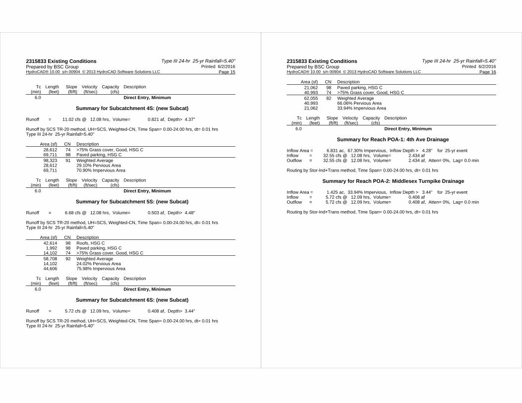
Type III 24-hr 25-yr Rainfall=5.40"2315833 Existing Conditions Printed 6/2/2016Prepared by BSC Group
Page 15HydroCAD® 10.00 s/n 00904 © 2013 HydroCAD Software Solutions LLC
Tc Length Slope Velocity Capacity Description(min) (feet) (ft/ft) (ft/sec) (cfs)
6.0 Direct Entry, Minimum
Summary for Subcatchment 4S: (new Subcat)
Runoff = 11.02 cfs @ 12.08 hrs, Volume= 0.821 af, Depth> 4.37"
Runoff by SCS TR-20 method, UH=SCS, Weighted-CN, Time Span= 0.00-24.00 hrs, dt= 0.01 hrsType III 24-hr 25-yr Rainfall=5.40"
Area (sf) CN Description28,612 74 >75% Grass cover, Good, HSG C69,711 98 Paved parking, HSG C98,323 91 Weighted Average28,612 29.10% Pervious Area69,711 70.90% Impervious Area
Tc Length Slope Velocity Capacity Description(min) (feet) (ft/ft) (ft/sec) (cfs)
6.0 Direct Entry, Minimum
Summary for Subcatchment 5S: (new Subcat)
Runoff = 6.68 cfs @ 12.08 hrs, Volume= 0.503 af, Depth> 4.48"
Runoff by SCS TR-20 method, UH=SCS, Weighted-CN, Time Span= 0.00-24.00 hrs, dt= 0.01 hrsType III 24-hr 25-yr Rainfall=5.40"
Area (sf) CN Description42,614 98 Roofs, HSG C
1,992 98 Paved parking, HSG C14,102 74 >75% Grass cover, Good, HSG C58,708 92 Weighted Average14,102 24.02% Pervious Area44,606 75.98% Impervious Area
Tc Length Slope Velocity Capacity Description(min) (feet) (ft/ft) (ft/sec) (cfs)
6.0 Direct Entry, Minimum
Summary for Subcatchment 6S: (new Subcat)
Runoff = 5.72 cfs @ 12.09 hrs, Volume= 0.408 af, Depth> 3.44"
Runoff by SCS TR-20 method, UH=SCS, Weighted-CN, Time Span= 0.00-24.00 hrs, dt= 0.01 hrsType III 24-hr 25-yr Rainfall=5.40"
Type III 24-hr 25-yr Rainfall=5.40"2315833 Existing Conditions Printed 6/2/2016Prepared by BSC Group
Page 16HydroCAD® 10.00 s/n 00904 © 2013 HydroCAD Software Solutions LLC
Area (sf) CN Description21,062 98 Paved parking, HSG C40,993 74 >75% Grass cover, Good, HSG C62,055 82 Weighted Average40,993 66.06% Pervious Area21,062 33.94% Impervious Area
Tc Length Slope Velocity Capacity Description(min) (feet) (ft/ft) (ft/sec) (cfs)
6.0 Direct Entry, Minimum
Summary for Reach POA-1: 4th Ave Drainage
Inflow Area = 6.831 ac, 67.30% Impervious, Inflow Depth > 4.28" for 25-yr eventInflow = 32.55 cfs @ 12.08 hrs, Volume= 2.434 afOutflow = 32.55 cfs @ 12.08 hrs, Volume= 2.434 af, Atten= 0%, Lag= 0.0 min
Routing by Stor-Ind+Trans method, Time Span= 0.00-24.00 hrs, dt= 0.01 hrs
Summary for Reach POA-2: Middlesex Turnpike Drainage
Inflow Area = 1.425 ac, 33.94% Impervious, Inflow Depth > 3.44" for 25-yr eventInflow = 5.72 cfs @ 12.09 hrs, Volume= 0.408 afOutflow = 5.72 cfs @ 12.09 hrs, Volume= 0.408 af, Atten= 0%, Lag= 0.0 min
Routing by Stor-Ind+Trans method, Time Span= 0.00-24.00 hrs, dt= 0.01 hrs
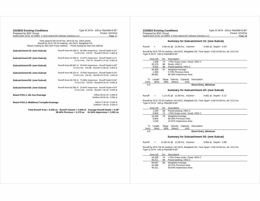
Type III 24-hr 100-yr Rainfall=6.60"2315833 Existing Conditions Printed 6/2/2016Prepared by BSC Group
Page 17HydroCAD® 10.00 s/n 00904 © 2013 HydroCAD Software Solutions LLC
Time span=0.00-24.00 hrs, dt=0.01 hrs, 2401 pointsRunoff by SCS TR-20 method, UH=SCS, Weighted-CN
Reach routing by Stor-Ind+Trans method - Pond routing by Stor-Ind method
Runoff Area=40,489 sf 96.28% Impervious Runoff Depth>6.24"Subcatchment 1S: (new Subcat) Tc=6.0 min CN=97 Runoff=5.99 cfs 0.483 af
Runoff Area=10,349 sf 14.97% Impervious Runoff Depth>4.11"Subcatchment 2S: (new Subcat) Tc=6.0 min CN=78 Runoff=1.14 cfs 0.081 af
Runoff Area=89,697 sf 50.63% Impervious Runoff Depth>4.98"Subcatchment 3S: (new Subcat) Tc=6.0 min CN=86 Runoff=11.68 cfs 0.854 af
Runoff Area=98,323 sf 70.90% Impervious Runoff Depth>5.54"Subcatchment 4S: (new Subcat) Tc=6.0 min CN=91 Runoff=13.79 cfs 1.042 af
Runoff Area=58,708 sf 75.98% Impervious Runoff Depth>5.66"Subcatchment 5S: (new Subcat) Tc=6.0 min CN=92 Runoff=8.33 cfs 0.635 af
Runoff Area=62,055 sf 33.94% Impervious Runoff Depth>4.54"Subcatchment 6S: (new Subcat) Tc=6.0 min CN=82 Runoff=7.49 cfs 0.539 af
Inflow=40.93 cfs 3.096 afReach POA-1: 4th Ave Drainage Outflow=40.93 cfs 3.096 af
Inflow=7.49 cfs 0.539 afReach POA-2: Middlesex Turnpike Drainage Outflow=7.49 cfs 0.539 af
Total Runoff Area = 8.256 ac Runoff Volume = 3.635 af Average Runoff Depth = 5.28"38.46% Pervious = 3.175 ac 61.54% Impervious = 5.081 ac
Type III 24-hr 100-yr Rainfall=6.60"2315833 Existing Conditions Printed 6/2/2016Prepared by BSC Group
Page 18HydroCAD® 10.00 s/n 00904 © 2013 HydroCAD Software Solutions LLC
Summary for Subcatchment 1S: (new Subcat)
Runoff = 5.99 cfs @ 12.08 hrs, Volume= 0.483 af, Depth> 6.24"
Runoff by SCS TR-20 method, UH=SCS, Weighted-CN, Time Span= 0.00-24.00 hrs, dt= 0.01 hrsType III 24-hr 100-yr Rainfall=6.60"
Area (sf) CN Description1,508 74 >75% Grass cover, Good, HSG C
30,379 98 Roofs, HSG C8,602 98 Paved parking, HSG C
40,489 97 Weighted Average1,508 3.72% Pervious Area
38,981 96.28% Impervious Area
Tc Length Slope Velocity Capacity Description(min) (feet) (ft/ft) (ft/sec) (cfs)
6.0 Direct Entry, Minimum
Summary for Subcatchment 2S: (new Subcat)
Runoff = 1.14 cfs @ 12.09 hrs, Volume= 0.081 af, Depth> 4.11"
Runoff by SCS TR-20 method, UH=SCS, Weighted-CN, Time Span= 0.00-24.00 hrs, dt= 0.01 hrsType III 24-hr 100-yr Rainfall=6.60"
Area (sf) CN Description1,549 98 Paved parking, HSG C8,800 74 >75% Grass cover, Good, HSG C
10,349 78 Weighted Average8,800 85.03% Pervious Area1,549 14.97% Impervious Area
Tc Length Slope Velocity Capacity Description(min) (feet) (ft/ft) (ft/sec) (cfs)
6.0 Direct Entry, Minimum
Summary for Subcatchment 3S: (new Subcat)
Runoff = 11.68 cfs @ 12.09 hrs, Volume= 0.854 af, Depth> 4.98"
Runoff by SCS TR-20 method, UH=SCS, Weighted-CN, Time Span= 0.00-24.00 hrs, dt= 0.01 hrsType III 24-hr 100-yr Rainfall=6.60"
Area (sf) CN Description44,286 74 >75% Grass cover, Good, HSG C45,411 98 Paved parking, HSG C89,697 86 Weighted Average44,286 49.37% Pervious Area45,411 50.63% Impervious Area

Type III 24-hr 100-yr Rainfall=6.60"2315833 Existing Conditions Printed 6/2/2016Prepared by BSC Group
Page 19HydroCAD® 10.00 s/n 00904 © 2013 HydroCAD Software Solutions LLC
Tc Length Slope Velocity Capacity Description(min) (feet) (ft/ft) (ft/sec) (cfs)
6.0 Direct Entry, Minimum
Summary for Subcatchment 4S: (new Subcat)
Runoff = 13.79 cfs @ 12.08 hrs, Volume= 1.042 af, Depth> 5.54"
Runoff by SCS TR-20 method, UH=SCS, Weighted-CN, Time Span= 0.00-24.00 hrs, dt= 0.01 hrsType III 24-hr 100-yr Rainfall=6.60"
Area (sf) CN Description28,612 74 >75% Grass cover, Good, HSG C69,711 98 Paved parking, HSG C98,323 91 Weighted Average28,612 29.10% Pervious Area69,711 70.90% Impervious Area
Tc Length Slope Velocity Capacity Description(min) (feet) (ft/ft) (ft/sec) (cfs)
6.0 Direct Entry, Minimum
Summary for Subcatchment 5S: (new Subcat)
Runoff = 8.33 cfs @ 12.08 hrs, Volume= 0.635 af, Depth> 5.66"
Runoff by SCS TR-20 method, UH=SCS, Weighted-CN, Time Span= 0.00-24.00 hrs, dt= 0.01 hrsType III 24-hr 100-yr Rainfall=6.60"
Area (sf) CN Description42,614 98 Roofs, HSG C
1,992 98 Paved parking, HSG C14,102 74 >75% Grass cover, Good, HSG C58,708 92 Weighted Average14,102 24.02% Pervious Area44,606 75.98% Impervious Area
Tc Length Slope Velocity Capacity Description(min) (feet) (ft/ft) (ft/sec) (cfs)
6.0 Direct Entry, Minimum
Summary for Subcatchment 6S: (new Subcat)
Runoff = 7.49 cfs @ 12.09 hrs, Volume= 0.539 af, Depth> 4.54"
Runoff by SCS TR-20 method, UH=SCS, Weighted-CN, Time Span= 0.00-24.00 hrs, dt= 0.01 hrsType III 24-hr 100-yr Rainfall=6.60"
Type III 24-hr 100-yr Rainfall=6.60"2315833 Existing Conditions Printed 6/2/2016Prepared by BSC Group
Page 20HydroCAD® 10.00 s/n 00904 © 2013 HydroCAD Software Solutions LLC
Area (sf) CN Description21,062 98 Paved parking, HSG C40,993 74 >75% Grass cover, Good, HSG C62,055 82 Weighted Average40,993 66.06% Pervious Area21,062 33.94% Impervious Area
Tc Length Slope Velocity Capacity Description(min) (feet) (ft/ft) (ft/sec) (cfs)
6.0 Direct Entry, Minimum
Summary for Reach POA-1: 4th Ave Drainage
Inflow Area = 6.831 ac, 67.30% Impervious, Inflow Depth > 5.44" for 100-yr eventInflow = 40.93 cfs @ 12.08 hrs, Volume= 3.096 afOutflow = 40.93 cfs @ 12.08 hrs, Volume= 3.096 af, Atten= 0%, Lag= 0.0 min
Routing by Stor-Ind+Trans method, Time Span= 0.00-24.00 hrs, dt= 0.01 hrs
Summary for Reach POA-2: Middlesex Turnpike Drainage
Inflow Area = 1.425 ac, 33.94% Impervious, Inflow Depth > 4.54" for 100-yr eventInflow = 7.49 cfs @ 12.09 hrs, Volume= 0.539 afOutflow = 7.49 cfs @ 12.09 hrs, Volume= 0.539 af, Atten= 0%, Lag= 0.0 min
Routing by Stor-Ind+Trans method, Time Span= 0.00-24.00 hrs, dt= 0.01 hrs
Stormwater Report174/186 Middlesex Turnpike
Burlington, Massachusetts
4.03
PROPOSED CONDITIONS WATERSHED ANALYSIS PLAN
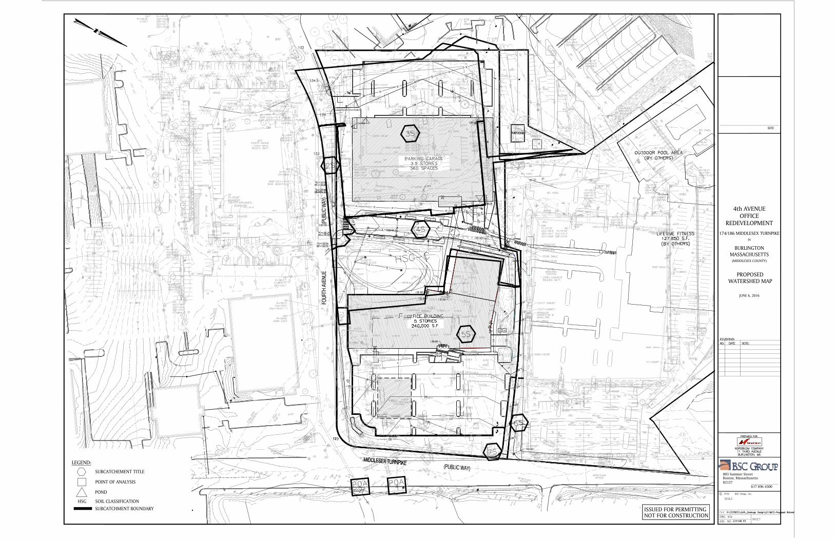
PROPOSEDWATERSHED MAP
ISSUED FOR PERMITTINGNOT FOR CONSTRUCTION
617 896 430002127Boston, Massachusetts803 Summer Street
IN
4th AVENUEOFFICE
174/186 MIDDLESEX TURNPIKE
BURLINGTONMASSACHUSETTS
(MIDDLESEX COUNTY)
REDEVELOPMENT
JUNE 6, 2016
LEGEND:
SUBCATCHEMENT TITLE
POINT OF ANALYSIS
POND
HSG SOIL CLASSIFICATION
SUBCATCHMENT BOUNDARY

Stormwater Report174/186 Middlesex Turnpike
Burlington, Massachusetts
4.04
PROPOSED CONDITIONS HYDROCAD PRINTOUTS
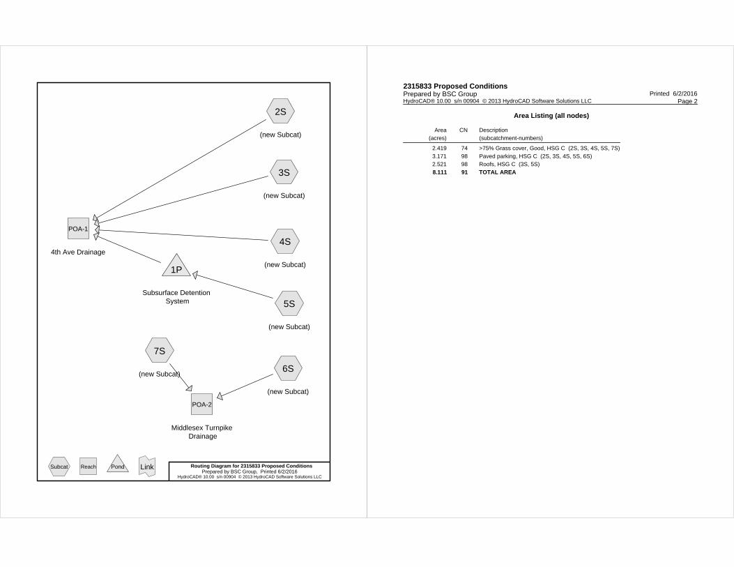
2S
(new Subcat)
3S
(new Subcat)
4S
(new Subcat)
5S
(new Subcat)
6S
(new Subcat)
7S
(new Subcat)
POA-1
4th Ave Drainage
POA-2
Middlesex Turnpike Drainage
1P
Subsurface Detention System
Routing Diagram for 2315833 Proposed ConditionsPrepared by BSC Group, Printed 6/2/2016
HydroCAD® 10.00 s/n 00904 © 2013 HydroCAD Software Solutions LLC
Subcat Reach Pond Link
2315833 Proposed Conditions Printed 6/2/2016Prepared by BSC Group
Page 2HydroCAD® 10.00 s/n 00904 © 2013 HydroCAD Software Solutions LLC
Area Listing (all nodes)
Area(acres)
CN Description(subcatchment-numbers)
2.419 74 >75% Grass cover, Good, HSG C (2S, 3S, 4S, 5S, 7S)3.171 98 Paved parking, HSG C (2S, 3S, 4S, 5S, 6S)2.521 98 Roofs, HSG C (3S, 5S)
8.111 91 TOTAL AREA
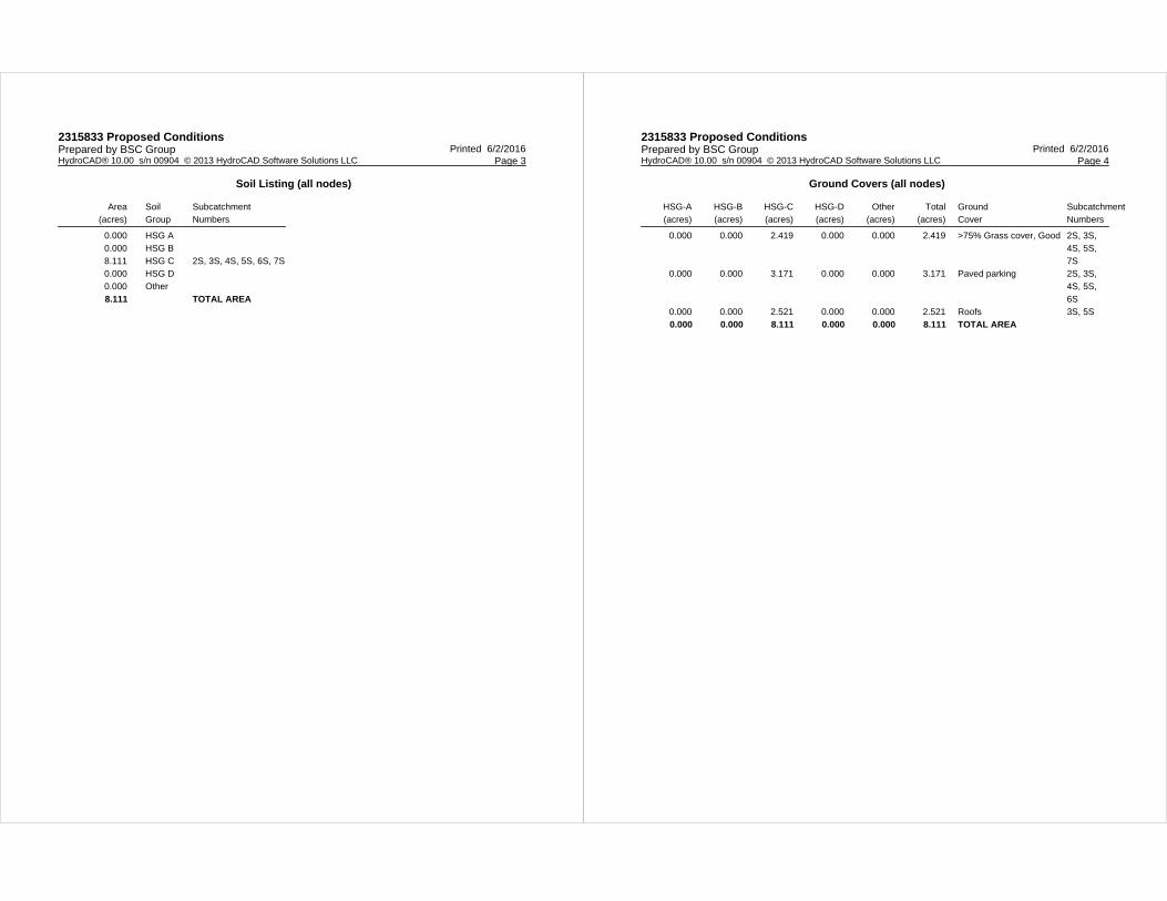
2315833 Proposed Conditions Printed 6/2/2016Prepared by BSC Group
Page 3HydroCAD® 10.00 s/n 00904 © 2013 HydroCAD Software Solutions LLC
Soil Listing (all nodes)
Area(acres)
SoilGroup
SubcatchmentNumbers
0.000 HSG A0.000 HSG B8.111 HSG C 2S, 3S, 4S, 5S, 6S, 7S0.000 HSG D0.000 Other
8.111 TOTAL AREA
2315833 Proposed Conditions Printed 6/2/2016Prepared by BSC Group
Page 4HydroCAD® 10.00 s/n 00904 © 2013 HydroCAD Software Solutions LLC
Ground Covers (all nodes)
HSG-A(acres)
HSG-B(acres)
HSG-C(acres)
HSG-D(acres)
Other(acres)
Total(acres)
GroundCover
SubcatchmentNumbers
0.000 0.000 2.419 0.000 0.000 2.419 >75% Grass cover, Good 2S, 3S, 4S, 5S, 7S
0.000 0.000 3.171 0.000 0.000 3.171 Paved parking 2S, 3S, 4S, 5S, 6S
0.000 0.000 2.521 0.000 0.000 2.521 Roofs 3S, 5S
0.000 0.000 8.111 0.000 0.000 8.111 TOTAL AREA
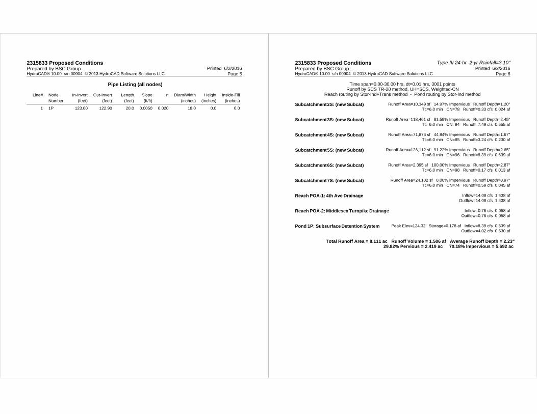
2315833 Proposed Conditions Printed 6/2/2016Prepared by BSC Group
Page 5HydroCAD® 10.00 s/n 00904 © 2013 HydroCAD Software Solutions LLC
Pipe Listing (all nodes)
Line# NodeNumber
In-Invert(feet)
Out-Invert(feet)
Length(feet)
Slope(ft/ft)
n Diam/Width(inches)
Height(inches)
Inside-Fill(inches)
1 1P 123.00 122.90 20.0 0.0050 0.020 18.0 0.0 0.0
Type III 24-hr 2-yr Rainfall=3.10"2315833 Proposed Conditions Printed 6/2/2016Prepared by BSC Group
Page 6HydroCAD® 10.00 s/n 00904 © 2013 HydroCAD Software Solutions LLC
Time span=0.00-30.00 hrs, dt=0.01 hrs, 3001 pointsRunoff by SCS TR-20 method, UH=SCS, Weighted-CN
Reach routing by Stor-Ind+Trans method - Pond routing by Stor-Ind method
Runoff Area=10,349 sf 14.97% Impervious Runoff Depth=1.20"Subcatchment 2S: (new Subcat) Tc=6.0 min CN=78 Runoff=0.33 cfs 0.024 af
Runoff Area=118,461 sf 81.59% Impervious Runoff Depth=2.45"Subcatchment 3S: (new Subcat) Tc=6.0 min CN=94 Runoff=7.49 cfs 0.555 af
Runoff Area=71,876 sf 44.94% Impervious Runoff Depth=1.67"Subcatchment 4S: (new Subcat) Tc=6.0 min CN=85 Runoff=3.24 cfs 0.230 af
Runoff Area=126,112 sf 91.22% Impervious Runoff Depth=2.65"Subcatchment 5S: (new Subcat) Tc=6.0 min CN=96 Runoff=8.39 cfs 0.639 af
Runoff Area=2,395 sf 100.00% Impervious Runoff Depth=2.87"Subcatchment 6S: (new Subcat) Tc=6.0 min CN=98 Runoff=0.17 cfs 0.013 af
Runoff Area=24,102 sf 0.00% Impervious Runoff Depth=0.97"Subcatchment 7S: (new Subcat) Tc=6.0 min CN=74 Runoff=0.59 cfs 0.045 af
Inflow=14.08 cfs 1.438 afReach POA-1: 4th Ave Drainage Outflow=14.08 cfs 1.438 af
Inflow=0.76 cfs 0.058 afReach POA-2: Middlesex Turnpike Drainage Outflow=0.76 cfs 0.058 af
Peak Elev=124.32' Storage=0.178 af Inflow=8.39 cfs 0.639 afPond 1P: Subsurface Detention System Outflow=4.02 cfs 0.630 af
Total Runoff Area = 8.111 ac Runoff Volume = 1.506 af Average Runoff Depth = 2.23"29.82% Pervious = 2.419 ac 70.18% Impervious = 5.692 ac
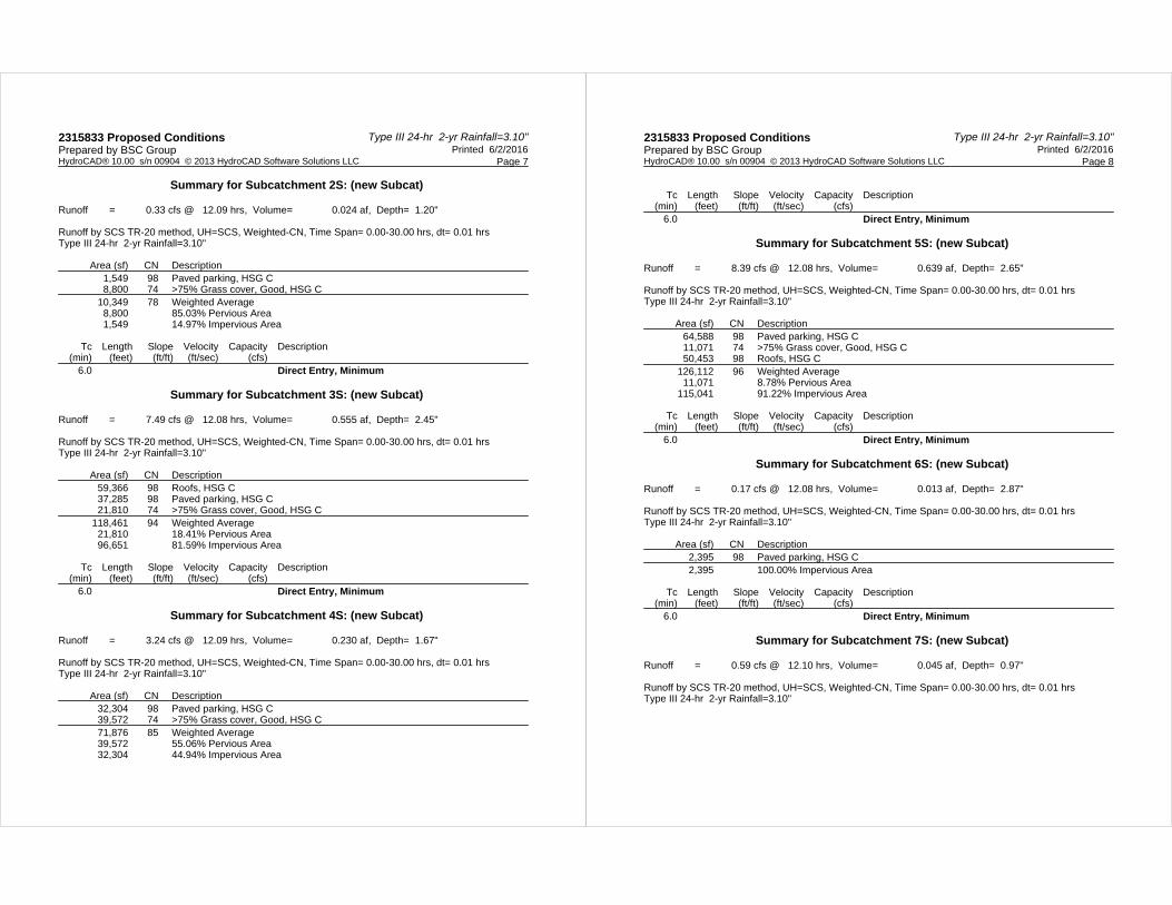
Type III 24-hr 2-yr Rainfall=3.10"2315833 Proposed Conditions Printed 6/2/2016Prepared by BSC Group
Page 7HydroCAD® 10.00 s/n 00904 © 2013 HydroCAD Software Solutions LLC
Summary for Subcatchment 2S: (new Subcat)
Runoff = 0.33 cfs @ 12.09 hrs, Volume= 0.024 af, Depth= 1.20"
Runoff by SCS TR-20 method, UH=SCS, Weighted-CN, Time Span= 0.00-30.00 hrs, dt= 0.01 hrsType III 24-hr 2-yr Rainfall=3.10"
Area (sf) CN Description1,549 98 Paved parking, HSG C8,800 74 >75% Grass cover, Good, HSG C
10,349 78 Weighted Average8,800 85.03% Pervious Area1,549 14.97% Impervious Area
Tc Length Slope Velocity Capacity Description(min) (feet) (ft/ft) (ft/sec) (cfs)
6.0 Direct Entry, Minimum
Summary for Subcatchment 3S: (new Subcat)
Runoff = 7.49 cfs @ 12.08 hrs, Volume= 0.555 af, Depth= 2.45"
Runoff by SCS TR-20 method, UH=SCS, Weighted-CN, Time Span= 0.00-30.00 hrs, dt= 0.01 hrsType III 24-hr 2-yr Rainfall=3.10"
Area (sf) CN Description59,366 98 Roofs, HSG C37,285 98 Paved parking, HSG C21,810 74 >75% Grass cover, Good, HSG C
118,461 94 Weighted Average21,810 18.41% Pervious Area96,651 81.59% Impervious Area
Tc Length Slope Velocity Capacity Description(min) (feet) (ft/ft) (ft/sec) (cfs)
6.0 Direct Entry, Minimum
Summary for Subcatchment 4S: (new Subcat)
Runoff = 3.24 cfs @ 12.09 hrs, Volume= 0.230 af, Depth= 1.67"
Runoff by SCS TR-20 method, UH=SCS, Weighted-CN, Time Span= 0.00-30.00 hrs, dt= 0.01 hrsType III 24-hr 2-yr Rainfall=3.10"
Area (sf) CN Description32,304 98 Paved parking, HSG C39,572 74 >75% Grass cover, Good, HSG C71,876 85 Weighted Average39,572 55.06% Pervious Area32,304 44.94% Impervious Area
Type III 24-hr 2-yr Rainfall=3.10"2315833 Proposed Conditions Printed 6/2/2016Prepared by BSC Group
Page 8HydroCAD® 10.00 s/n 00904 © 2013 HydroCAD Software Solutions LLC
Tc Length Slope Velocity Capacity Description(min) (feet) (ft/ft) (ft/sec) (cfs)
6.0 Direct Entry, Minimum
Summary for Subcatchment 5S: (new Subcat)
Runoff = 8.39 cfs @ 12.08 hrs, Volume= 0.639 af, Depth= 2.65"
Runoff by SCS TR-20 method, UH=SCS, Weighted-CN, Time Span= 0.00-30.00 hrs, dt= 0.01 hrsType III 24-hr 2-yr Rainfall=3.10"
Area (sf) CN Description64,588 98 Paved parking, HSG C11,071 74 >75% Grass cover, Good, HSG C50,453 98 Roofs, HSG C
126,112 96 Weighted Average11,071 8.78% Pervious Area
115,041 91.22% Impervious Area
Tc Length Slope Velocity Capacity Description(min) (feet) (ft/ft) (ft/sec) (cfs)
6.0 Direct Entry, Minimum
Summary for Subcatchment 6S: (new Subcat)
Runoff = 0.17 cfs @ 12.08 hrs, Volume= 0.013 af, Depth= 2.87"
Runoff by SCS TR-20 method, UH=SCS, Weighted-CN, Time Span= 0.00-30.00 hrs, dt= 0.01 hrsType III 24-hr 2-yr Rainfall=3.10"
Area (sf) CN Description2,395 98 Paved parking, HSG C2,395 100.00% Impervious Area
Tc Length Slope Velocity Capacity Description(min) (feet) (ft/ft) (ft/sec) (cfs)
6.0 Direct Entry, Minimum
Summary for Subcatchment 7S: (new Subcat)
Runoff = 0.59 cfs @ 12.10 hrs, Volume= 0.045 af, Depth= 0.97"
Runoff by SCS TR-20 method, UH=SCS, Weighted-CN, Time Span= 0.00-30.00 hrs, dt= 0.01 hrsType III 24-hr 2-yr Rainfall=3.10"
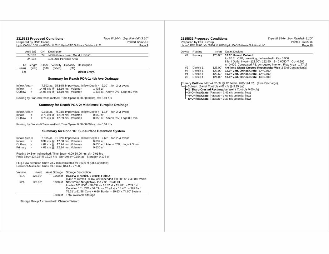
Type III 24-hr 2-yr Rainfall=3.10"2315833 Proposed Conditions Printed 6/2/2016Prepared by BSC Group
Page 9HydroCAD® 10.00 s/n 00904 © 2013 HydroCAD Software Solutions LLC
Area (sf) CN Description24,102 74 >75% Grass cover, Good, HSG C24,102 100.00% Pervious Area
Tc Length Slope Velocity Capacity Description(min) (feet) (ft/ft) (ft/sec) (cfs)
6.0 Direct Entry,
Summary for Reach POA-1: 4th Ave Drainage
Inflow Area = 7.502 ac, 75.14% Impervious, Inflow Depth > 2.30" for 2-yr eventInflow = 14.08 cfs @ 12.10 hrs, Volume= 1.438 afOutflow = 14.08 cfs @ 12.10 hrs, Volume= 1.438 af, Atten= 0%, Lag= 0.0 min
Routing by Stor-Ind+Trans method, Time Span= 0.00-30.00 hrs, dt= 0.01 hrs
Summary for Reach POA-2: Middlesex Turnpike Drainage
Inflow Area = 0.608 ac, 9.04% Impervious, Inflow Depth = 1.14" for 2-yr eventInflow = 0.76 cfs @ 12.09 hrs, Volume= 0.058 afOutflow = 0.76 cfs @ 12.09 hrs, Volume= 0.058 af, Atten= 0%, Lag= 0.0 min
Routing by Stor-Ind+Trans method, Time Span= 0.00-30.00 hrs, dt= 0.01 hrs
Summary for Pond 1P: Subsurface Detention System
Inflow Area = 2.895 ac, 91.22% Impervious, Inflow Depth = 2.65" for 2-yr eventInflow = 8.39 cfs @ 12.08 hrs, Volume= 0.639 afOutflow = 4.02 cfs @ 12.24 hrs, Volume= 0.630 af, Atten= 52%, Lag= 9.3 minPrimary = 4.02 cfs @ 12.24 hrs, Volume= 0.630 af
Routing by Stor-Ind method, Time Span= 0.00-30.00 hrs, dt= 0.01 hrsPeak Elev= 124.32' @ 12.24 hrs Surf.Area= 0.154 ac Storage= 0.178 af
Plug-Flow detention time= 78.7 min calculated for 0.630 af (98% of inflow)Center-of-Mass det. time= 69.5 min ( 844.4 - 775.0 )
Volume Invert Avail.Storage Storage Description#1A 123.00' 0.000 af 89.63'W x 74.90'L x 3.00'H Field A
0.462 af Overall - 0.462 af Embedded = 0.000 af x 40.0% Voids#2A 123.00' 0.338 af StormTrap SingleTrap 2-6 x 36 Inside #1
Inside= 101.8"W x 30.0"H => 18.82 sf x 15.40'L = 289.8 cfOutside= 101.8"W x 36.0"H => 25.44 sf x 15.40'L = 391.6 cf76.31' x 61.58' Core + 6.66' Border = 89.63' x 74.90' System
0.338 af Total Available Storage
Storage Group A created with Chamber Wizard
Type III 24-hr 2-yr Rainfall=3.10"2315833 Proposed Conditions Printed 6/2/2016Prepared by BSC Group
Page 10HydroCAD® 10.00 s/n 00904 © 2013 HydroCAD Software Solutions LLC
Device Routing Invert Outlet Devices#1 Primary 123.00' 18.0" Round Culvert
L= 20.0' CPP, projecting, no headwall, Ke= 0.900 Inlet / Outlet Invert= 123.00' / 122.90' S= 0.0050 '/' Cc= 0.900 n= 0.020 Corrugated PE, corrugated interior, Flow Area= 1.77 sf
#2 Device 1 126.00' 4.0' long Sharp-Crested Rectangular Weir 2 End Contraction(s) #3 Device 1 123.00' 12.0" Vert. Orifice/Grate C= 0.600 #4 Device 1 123.50' 10.0" Vert. Orifice/Grate C= 0.600 #5 Device 1 124.00' 10.0" Vert. Orifice/Grate C= 0.600
Primary OutFlow Max=4.02 cfs @ 12.24 hrs HW=124.32' (Free Discharge)1=Culvert (Barrel Controls 4.02 cfs @ 3.25 fps)
2=Sharp-Crested Rectangular Weir ( Controls 0.00 cfs)3=Orifice/Grate (Passes < 3.42 cfs potential flow)4=Orifice/Grate (Passes < 1.67 cfs potential flow)5=Orifice/Grate (Passes < 0.37 cfs potential flow)

Type III 24-hr 10-yr Rainfall=4.50"2315833 Proposed Conditions Printed 6/2/2016Prepared by BSC Group
Page 11HydroCAD® 10.00 s/n 00904 © 2013 HydroCAD Software Solutions LLC
Time span=0.00-30.00 hrs, dt=0.01 hrs, 3001 pointsRunoff by SCS TR-20 method, UH=SCS, Weighted-CN
Reach routing by Stor-Ind+Trans method - Pond routing by Stor-Ind method
Runoff Area=10,349 sf 14.97% Impervious Runoff Depth=2.29"Subcatchment 2S: (new Subcat) Tc=6.0 min CN=78 Runoff=0.64 cfs 0.045 af
Runoff Area=118,461 sf 81.59% Impervious Runoff Depth=3.82"Subcatchment 3S: (new Subcat) Tc=6.0 min CN=94 Runoff=11.39 cfs 0.865 af
Runoff Area=71,876 sf 44.94% Impervious Runoff Depth=2.91"Subcatchment 4S: (new Subcat) Tc=6.0 min CN=85 Runoff=5.60 cfs 0.400 af
Runoff Area=126,112 sf 91.22% Impervious Runoff Depth=4.04"Subcatchment 5S: (new Subcat) Tc=6.0 min CN=96 Runoff=12.48 cfs 0.974 af
Runoff Area=2,395 sf 100.00% Impervious Runoff Depth=4.26"Subcatchment 6S: (new Subcat) Tc=6.0 min CN=98 Runoff=0.24 cfs 0.020 af
Runoff Area=24,102 sf 0.00% Impervious Runoff Depth=1.97"Subcatchment 7S: (new Subcat) Tc=6.0 min CN=74 Runoff=1.27 cfs 0.091 af
Inflow=22.53 cfs 2.274 afReach POA-1: 4th Ave Drainage Outflow=22.53 cfs 2.274 af
Inflow=1.51 cfs 0.110 afReach POA-2: Middlesex Turnpike Drainage Outflow=1.51 cfs 0.110 af
Peak Elev=124.79' Storage=0.242 af Inflow=12.48 cfs 0.974 afPond 1P: Subsurface Detention System Outflow=6.15 cfs 0.964 af
Total Runoff Area = 8.111 ac Runoff Volume = 2.394 af Average Runoff Depth = 3.54"29.82% Pervious = 2.419 ac 70.18% Impervious = 5.692 ac
Type III 24-hr 10-yr Rainfall=4.50"2315833 Proposed Conditions Printed 6/2/2016Prepared by BSC Group
Page 12HydroCAD® 10.00 s/n 00904 © 2013 HydroCAD Software Solutions LLC
Summary for Subcatchment 2S: (new Subcat)
Runoff = 0.64 cfs @ 12.09 hrs, Volume= 0.045 af, Depth= 2.29"
Runoff by SCS TR-20 method, UH=SCS, Weighted-CN, Time Span= 0.00-30.00 hrs, dt= 0.01 hrsType III 24-hr 10-yr Rainfall=4.50"
Area (sf) CN Description1,549 98 Paved parking, HSG C8,800 74 >75% Grass cover, Good, HSG C
10,349 78 Weighted Average8,800 85.03% Pervious Area1,549 14.97% Impervious Area
Tc Length Slope Velocity Capacity Description(min) (feet) (ft/ft) (ft/sec) (cfs)
6.0 Direct Entry, Minimum
Summary for Subcatchment 3S: (new Subcat)
Runoff = 11.39 cfs @ 12.08 hrs, Volume= 0.865 af, Depth= 3.82"
Runoff by SCS TR-20 method, UH=SCS, Weighted-CN, Time Span= 0.00-30.00 hrs, dt= 0.01 hrsType III 24-hr 10-yr Rainfall=4.50"
Area (sf) CN Description59,366 98 Roofs, HSG C37,285 98 Paved parking, HSG C21,810 74 >75% Grass cover, Good, HSG C
118,461 94 Weighted Average21,810 18.41% Pervious Area96,651 81.59% Impervious Area
Tc Length Slope Velocity Capacity Description(min) (feet) (ft/ft) (ft/sec) (cfs)
6.0 Direct Entry, Minimum
Summary for Subcatchment 4S: (new Subcat)
Runoff = 5.60 cfs @ 12.09 hrs, Volume= 0.400 af, Depth= 2.91"
Runoff by SCS TR-20 method, UH=SCS, Weighted-CN, Time Span= 0.00-30.00 hrs, dt= 0.01 hrsType III 24-hr 10-yr Rainfall=4.50"
Area (sf) CN Description32,304 98 Paved parking, HSG C39,572 74 >75% Grass cover, Good, HSG C71,876 85 Weighted Average39,572 55.06% Pervious Area32,304 44.94% Impervious Area

Type III 24-hr 10-yr Rainfall=4.50"2315833 Proposed Conditions Printed 6/2/2016Prepared by BSC Group
Page 13HydroCAD® 10.00 s/n 00904 © 2013 HydroCAD Software Solutions LLC
Tc Length Slope Velocity Capacity Description(min) (feet) (ft/ft) (ft/sec) (cfs)
6.0 Direct Entry, Minimum
Summary for Subcatchment 5S: (new Subcat)
Runoff = 12.48 cfs @ 12.08 hrs, Volume= 0.974 af, Depth= 4.04"
Runoff by SCS TR-20 method, UH=SCS, Weighted-CN, Time Span= 0.00-30.00 hrs, dt= 0.01 hrsType III 24-hr 10-yr Rainfall=4.50"
Area (sf) CN Description64,588 98 Paved parking, HSG C11,071 74 >75% Grass cover, Good, HSG C50,453 98 Roofs, HSG C
126,112 96 Weighted Average11,071 8.78% Pervious Area
115,041 91.22% Impervious Area
Tc Length Slope Velocity Capacity Description(min) (feet) (ft/ft) (ft/sec) (cfs)
6.0 Direct Entry, Minimum
Summary for Subcatchment 6S: (new Subcat)
Runoff = 0.24 cfs @ 12.08 hrs, Volume= 0.020 af, Depth= 4.26"
Runoff by SCS TR-20 method, UH=SCS, Weighted-CN, Time Span= 0.00-30.00 hrs, dt= 0.01 hrsType III 24-hr 10-yr Rainfall=4.50"
Area (sf) CN Description2,395 98 Paved parking, HSG C2,395 100.00% Impervious Area
Tc Length Slope Velocity Capacity Description(min) (feet) (ft/ft) (ft/sec) (cfs)
6.0 Direct Entry, Minimum
Summary for Subcatchment 7S: (new Subcat)
Runoff = 1.27 cfs @ 12.09 hrs, Volume= 0.091 af, Depth= 1.97"
Runoff by SCS TR-20 method, UH=SCS, Weighted-CN, Time Span= 0.00-30.00 hrs, dt= 0.01 hrsType III 24-hr 10-yr Rainfall=4.50"
Type III 24-hr 10-yr Rainfall=4.50"2315833 Proposed Conditions Printed 6/2/2016Prepared by BSC Group
Page 14HydroCAD® 10.00 s/n 00904 © 2013 HydroCAD Software Solutions LLC
Area (sf) CN Description24,102 74 >75% Grass cover, Good, HSG C24,102 100.00% Pervious Area
Tc Length Slope Velocity Capacity Description(min) (feet) (ft/ft) (ft/sec) (cfs)
6.0 Direct Entry,
Summary for Reach POA-1: 4th Ave Drainage
Inflow Area = 7.502 ac, 75.14% Impervious, Inflow Depth > 3.64" for 10-yr eventInflow = 22.53 cfs @ 12.09 hrs, Volume= 2.274 afOutflow = 22.53 cfs @ 12.09 hrs, Volume= 2.274 af, Atten= 0%, Lag= 0.0 min
Routing by Stor-Ind+Trans method, Time Span= 0.00-30.00 hrs, dt= 0.01 hrs
Summary for Reach POA-2: Middlesex Turnpike Drainage
Inflow Area = 0.608 ac, 9.04% Impervious, Inflow Depth = 2.18" for 10-yr eventInflow = 1.51 cfs @ 12.09 hrs, Volume= 0.110 afOutflow = 1.51 cfs @ 12.09 hrs, Volume= 0.110 af, Atten= 0%, Lag= 0.0 min
Routing by Stor-Ind+Trans method, Time Span= 0.00-30.00 hrs, dt= 0.01 hrs
Summary for Pond 1P: Subsurface Detention System
Inflow Area = 2.895 ac, 91.22% Impervious, Inflow Depth = 4.04" for 10-yr eventInflow = 12.48 cfs @ 12.08 hrs, Volume= 0.974 afOutflow = 6.15 cfs @ 12.23 hrs, Volume= 0.964 af, Atten= 51%, Lag= 8.7 minPrimary = 6.15 cfs @ 12.23 hrs, Volume= 0.964 af
Routing by Stor-Ind method, Time Span= 0.00-30.00 hrs, dt= 0.01 hrsPeak Elev= 124.79' @ 12.23 hrs Surf.Area= 0.154 ac Storage= 0.242 af
Plug-Flow detention time= 66.3 min calculated for 0.964 af (99% of inflow)Center-of-Mass det. time= 59.6 min ( 824.6 - 765.0 )
Volume Invert Avail.Storage Storage Description#1A 123.00' 0.000 af 89.63'W x 74.90'L x 3.00'H Field A
0.462 af Overall - 0.462 af Embedded = 0.000 af x 40.0% Voids#2A 123.00' 0.338 af StormTrap SingleTrap 2-6 x 36 Inside #1
Inside= 101.8"W x 30.0"H => 18.82 sf x 15.40'L = 289.8 cfOutside= 101.8"W x 36.0"H => 25.44 sf x 15.40'L = 391.6 cf76.31' x 61.58' Core + 6.66' Border = 89.63' x 74.90' System
0.338 af Total Available Storage
Storage Group A created with Chamber Wizard
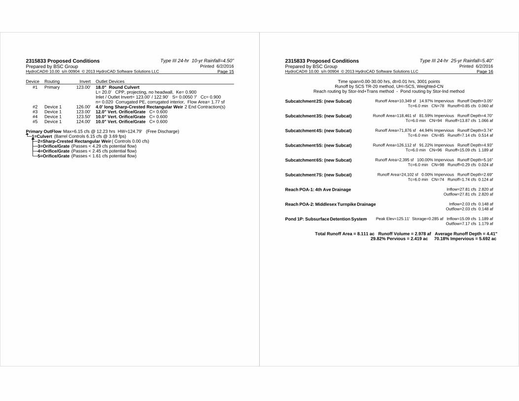
Type III 24-hr 10-yr Rainfall=4.50"2315833 Proposed Conditions Printed 6/2/2016Prepared by BSC Group
Page 15HydroCAD® 10.00 s/n 00904 © 2013 HydroCAD Software Solutions LLC
Device Routing Invert Outlet Devices#1 Primary 123.00' 18.0" Round Culvert
L= 20.0' CPP, projecting, no headwall, Ke= 0.900 Inlet / Outlet Invert= 123.00' / 122.90' S= 0.0050 '/' Cc= 0.900 n= 0.020 Corrugated PE, corrugated interior, Flow Area= 1.77 sf
#2 Device 1 126.00' 4.0' long Sharp-Crested Rectangular Weir 2 End Contraction(s) #3 Device 1 123.00' 12.0" Vert. Orifice/Grate C= 0.600 #4 Device 1 123.50' 10.0" Vert. Orifice/Grate C= 0.600 #5 Device 1 124.00' 10.0" Vert. Orifice/Grate C= 0.600
Primary OutFlow Max=6.15 cfs @ 12.23 hrs HW=124.79' (Free Discharge)1=Culvert (Barrel Controls 6.15 cfs @ 3.69 fps)
2=Sharp-Crested Rectangular Weir ( Controls 0.00 cfs)3=Orifice/Grate (Passes < 4.29 cfs potential flow)4=Orifice/Grate (Passes < 2.45 cfs potential flow)5=Orifice/Grate (Passes < 1.61 cfs potential flow)
Type III 24-hr 25-yr Rainfall=5.40"2315833 Proposed Conditions Printed 6/2/2016Prepared by BSC Group
Page 16HydroCAD® 10.00 s/n 00904 © 2013 HydroCAD Software Solutions LLC
Time span=0.00-30.00 hrs, dt=0.01 hrs, 3001 pointsRunoff by SCS TR-20 method, UH=SCS, Weighted-CN
Reach routing by Stor-Ind+Trans method - Pond routing by Stor-Ind method
Runoff Area=10,349 sf 14.97% Impervious Runoff Depth=3.05"Subcatchment 2S: (new Subcat) Tc=6.0 min CN=78 Runoff=0.85 cfs 0.060 af
Runoff Area=118,461 sf 81.59% Impervious Runoff Depth=4.70"Subcatchment 3S: (new Subcat) Tc=6.0 min CN=94 Runoff=13.87 cfs 1.066 af
Runoff Area=71,876 sf 44.94% Impervious Runoff Depth=3.74"Subcatchment 4S: (new Subcat) Tc=6.0 min CN=85 Runoff=7.14 cfs 0.514 af
Runoff Area=126,112 sf 91.22% Impervious Runoff Depth=4.93"Subcatchment 5S: (new Subcat) Tc=6.0 min CN=96 Runoff=15.09 cfs 1.189 af
Runoff Area=2,395 sf 100.00% Impervious Runoff Depth=5.16"Subcatchment 6S: (new Subcat) Tc=6.0 min CN=98 Runoff=0.29 cfs 0.024 af
Runoff Area=24,102 sf 0.00% Impervious Runoff Depth=2.69"Subcatchment 7S: (new Subcat) Tc=6.0 min CN=74 Runoff=1.74 cfs 0.124 af
Inflow=27.81 cfs 2.820 afReach POA-1: 4th Ave Drainage Outflow=27.81 cfs 2.820 af
Inflow=2.03 cfs 0.148 afReach POA-2: Middlesex Turnpike Drainage Outflow=2.03 cfs 0.148 af
Peak Elev=125.11' Storage=0.285 af Inflow=15.09 cfs 1.189 afPond 1P: Subsurface Detention System Outflow=7.17 cfs 1.179 af
Total Runoff Area = 8.111 ac Runoff Volume = 2.978 af Average Runoff Depth = 4.41"29.82% Pervious = 2.419 ac 70.18% Impervious = 5.692 ac

Type III 24-hr 25-yr Rainfall=5.40"2315833 Proposed Conditions Printed 6/2/2016Prepared by BSC Group
Page 17HydroCAD® 10.00 s/n 00904 © 2013 HydroCAD Software Solutions LLC
Summary for Subcatchment 2S: (new Subcat)
Runoff = 0.85 cfs @ 12.09 hrs, Volume= 0.060 af, Depth= 3.05"
Runoff by SCS TR-20 method, UH=SCS, Weighted-CN, Time Span= 0.00-30.00 hrs, dt= 0.01 hrsType III 24-hr 25-yr Rainfall=5.40"
Area (sf) CN Description1,549 98 Paved parking, HSG C8,800 74 >75% Grass cover, Good, HSG C
10,349 78 Weighted Average8,800 85.03% Pervious Area1,549 14.97% Impervious Area
Tc Length Slope Velocity Capacity Description(min) (feet) (ft/ft) (ft/sec) (cfs)
6.0 Direct Entry, Minimum
Summary for Subcatchment 3S: (new Subcat)
Runoff = 13.87 cfs @ 12.08 hrs, Volume= 1.066 af, Depth= 4.70"
Runoff by SCS TR-20 method, UH=SCS, Weighted-CN, Time Span= 0.00-30.00 hrs, dt= 0.01 hrsType III 24-hr 25-yr Rainfall=5.40"
Area (sf) CN Description59,366 98 Roofs, HSG C37,285 98 Paved parking, HSG C21,810 74 >75% Grass cover, Good, HSG C
118,461 94 Weighted Average21,810 18.41% Pervious Area96,651 81.59% Impervious Area
Tc Length Slope Velocity Capacity Description(min) (feet) (ft/ft) (ft/sec) (cfs)
6.0 Direct Entry, Minimum
Summary for Subcatchment 4S: (new Subcat)
Runoff = 7.14 cfs @ 12.09 hrs, Volume= 0.514 af, Depth= 3.74"
Runoff by SCS TR-20 method, UH=SCS, Weighted-CN, Time Span= 0.00-30.00 hrs, dt= 0.01 hrsType III 24-hr 25-yr Rainfall=5.40"
Area (sf) CN Description32,304 98 Paved parking, HSG C39,572 74 >75% Grass cover, Good, HSG C71,876 85 Weighted Average39,572 55.06% Pervious Area32,304 44.94% Impervious Area
Type III 24-hr 25-yr Rainfall=5.40"2315833 Proposed Conditions Printed 6/2/2016Prepared by BSC Group
Page 18HydroCAD® 10.00 s/n 00904 © 2013 HydroCAD Software Solutions LLC
Tc Length Slope Velocity Capacity Description(min) (feet) (ft/ft) (ft/sec) (cfs)
6.0 Direct Entry, Minimum
Summary for Subcatchment 5S: (new Subcat)
Runoff = 15.09 cfs @ 12.08 hrs, Volume= 1.189 af, Depth= 4.93"
Runoff by SCS TR-20 method, UH=SCS, Weighted-CN, Time Span= 0.00-30.00 hrs, dt= 0.01 hrsType III 24-hr 25-yr Rainfall=5.40"
Area (sf) CN Description64,588 98 Paved parking, HSG C11,071 74 >75% Grass cover, Good, HSG C50,453 98 Roofs, HSG C
126,112 96 Weighted Average11,071 8.78% Pervious Area
115,041 91.22% Impervious Area
Tc Length Slope Velocity Capacity Description(min) (feet) (ft/ft) (ft/sec) (cfs)
6.0 Direct Entry, Minimum
Summary for Subcatchment 6S: (new Subcat)
Runoff = 0.29 cfs @ 12.08 hrs, Volume= 0.024 af, Depth= 5.16"
Runoff by SCS TR-20 method, UH=SCS, Weighted-CN, Time Span= 0.00-30.00 hrs, dt= 0.01 hrsType III 24-hr 25-yr Rainfall=5.40"
Area (sf) CN Description2,395 98 Paved parking, HSG C2,395 100.00% Impervious Area
Tc Length Slope Velocity Capacity Description(min) (feet) (ft/ft) (ft/sec) (cfs)
6.0 Direct Entry, Minimum
Summary for Subcatchment 7S: (new Subcat)
Runoff = 1.74 cfs @ 12.09 hrs, Volume= 0.124 af, Depth= 2.69"
Runoff by SCS TR-20 method, UH=SCS, Weighted-CN, Time Span= 0.00-30.00 hrs, dt= 0.01 hrsType III 24-hr 25-yr Rainfall=5.40"

Type III 24-hr 25-yr Rainfall=5.40"2315833 Proposed Conditions Printed 6/2/2016Prepared by BSC Group
Page 19HydroCAD® 10.00 s/n 00904 © 2013 HydroCAD Software Solutions LLC
Area (sf) CN Description24,102 74 >75% Grass cover, Good, HSG C24,102 100.00% Pervious Area
Tc Length Slope Velocity Capacity Description(min) (feet) (ft/ft) (ft/sec) (cfs)
6.0 Direct Entry,
Summary for Reach POA-1: 4th Ave Drainage
Inflow Area = 7.502 ac, 75.14% Impervious, Inflow Depth > 4.51" for 25-yr eventInflow = 27.81 cfs @ 12.09 hrs, Volume= 2.820 afOutflow = 27.81 cfs @ 12.09 hrs, Volume= 2.820 af, Atten= 0%, Lag= 0.0 min
Routing by Stor-Ind+Trans method, Time Span= 0.00-30.00 hrs, dt= 0.01 hrs
Summary for Reach POA-2: Middlesex Turnpike Drainage
Inflow Area = 0.608 ac, 9.04% Impervious, Inflow Depth = 2.91" for 25-yr eventInflow = 2.03 cfs @ 12.09 hrs, Volume= 0.148 afOutflow = 2.03 cfs @ 12.09 hrs, Volume= 0.148 af, Atten= 0%, Lag= 0.0 min
Routing by Stor-Ind+Trans method, Time Span= 0.00-30.00 hrs, dt= 0.01 hrs
Summary for Pond 1P: Subsurface Detention System
Inflow Area = 2.895 ac, 91.22% Impervious, Inflow Depth = 4.93" for 25-yr eventInflow = 15.09 cfs @ 12.08 hrs, Volume= 1.189 afOutflow = 7.17 cfs @ 12.24 hrs, Volume= 1.179 af, Atten= 52%, Lag= 9.3 minPrimary = 7.17 cfs @ 12.24 hrs, Volume= 1.179 af
Routing by Stor-Ind method, Time Span= 0.00-30.00 hrs, dt= 0.01 hrsPeak Elev= 125.11' @ 12.24 hrs Surf.Area= 0.154 ac Storage= 0.285 af
Plug-Flow detention time= 61.5 min calculated for 1.179 af (99% of inflow)Center-of-Mass det. time= 55.8 min ( 816.4 - 760.6 )
Volume Invert Avail.Storage Storage Description#1A 123.00' 0.000 af 89.63'W x 74.90'L x 3.00'H Field A
0.462 af Overall - 0.462 af Embedded = 0.000 af x 40.0% Voids#2A 123.00' 0.338 af StormTrap SingleTrap 2-6 x 36 Inside #1
Inside= 101.8"W x 30.0"H => 18.82 sf x 15.40'L = 289.8 cfOutside= 101.8"W x 36.0"H => 25.44 sf x 15.40'L = 391.6 cf76.31' x 61.58' Core + 6.66' Border = 89.63' x 74.90' System
0.338 af Total Available Storage
Storage Group A created with Chamber Wizard
Type III 24-hr 25-yr Rainfall=5.40"2315833 Proposed Conditions Printed 6/2/2016Prepared by BSC Group
Page 20HydroCAD® 10.00 s/n 00904 © 2013 HydroCAD Software Solutions LLC
Device Routing Invert Outlet Devices#1 Primary 123.00' 18.0" Round Culvert
L= 20.0' CPP, projecting, no headwall, Ke= 0.900 Inlet / Outlet Invert= 123.00' / 122.90' S= 0.0050 '/' Cc= 0.900 n= 0.020 Corrugated PE, corrugated interior, Flow Area= 1.77 sf
#2 Device 1 126.00' 4.0' long Sharp-Crested Rectangular Weir 2 End Contraction(s) #3 Device 1 123.00' 12.0" Vert. Orifice/Grate C= 0.600 #4 Device 1 123.50' 10.0" Vert. Orifice/Grate C= 0.600 #5 Device 1 124.00' 10.0" Vert. Orifice/Grate C= 0.600
Primary OutFlow Max=7.17 cfs @ 12.24 hrs HW=125.11' (Free Discharge)1=Culvert (Barrel Controls 7.17 cfs @ 4.06 fps)
2=Sharp-Crested Rectangular Weir ( Controls 0.00 cfs)3=Orifice/Grate (Passes < 4.79 cfs potential flow)4=Orifice/Grate (Passes < 2.87 cfs potential flow)5=Orifice/Grate (Passes < 2.18 cfs potential flow)
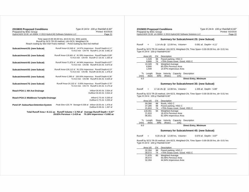
Type III 24-hr 100-yr Rainfall=6.60"2315833 Proposed Conditions Printed 6/2/2016Prepared by BSC Group
Page 21HydroCAD® 10.00 s/n 00904 © 2013 HydroCAD Software Solutions LLC
Time span=0.00-30.00 hrs, dt=0.01 hrs, 3001 pointsRunoff by SCS TR-20 method, UH=SCS, Weighted-CN
Reach routing by Stor-Ind+Trans method - Pond routing by Stor-Ind method
Runoff Area=10,349 sf 14.97% Impervious Runoff Depth=4.11"Subcatchment 2S: (new Subcat) Tc=6.0 min CN=78 Runoff=1.14 cfs 0.081 af
Runoff Area=118,461 sf 81.59% Impervious Runoff Depth=5.89"Subcatchment 3S: (new Subcat) Tc=6.0 min CN=94 Runoff=17.16 cfs 1.335 af
Runoff Area=71,876 sf 44.94% Impervious Runoff Depth=4.87"Subcatchment 4S: (new Subcat) Tc=6.0 min CN=85 Runoff=9.20 cfs 0.670 af
Runoff Area=126,112 sf 91.22% Impervious Runoff Depth=6.13"Subcatchment 5S: (new Subcat) Tc=6.0 min CN=96 Runoff=18.55 cfs 1.478 af
Runoff Area=2,395 sf 100.00% Impervious Runoff Depth=6.36"Subcatchment 6S: (new Subcat) Tc=6.0 min CN=98 Runoff=0.36 cfs 0.029 af
Runoff Area=24,102 sf 0.00% Impervious Runoff Depth=3.70"Subcatchment 7S: (new Subcat) Tc=6.0 min CN=74 Runoff=2.40 cfs 0.170 af
Inflow=34.40 cfs 3.554 afReach POA-1: 4th Ave Drainage Outflow=34.40 cfs 3.554 af
Inflow=2.75 cfs 0.200 afReach POA-2: Middlesex Turnpike Drainage Outflow=2.75 cfs 0.200 af
Peak Elev=125.74' Storage=0.338 af Inflow=18.55 cfs 1.478 afPond 1P: Subsurface Detention System Outflow=9.48 cfs 1.467 af
Total Runoff Area = 8.111 ac Runoff Volume = 3.764 af Average Runoff Depth = 5.57"29.82% Pervious = 2.419 ac 70.18% Impervious = 5.692 ac
Type III 24-hr 100-yr Rainfall=6.60"2315833 Proposed Conditions Printed 6/2/2016Prepared by BSC Group
Page 22HydroCAD® 10.00 s/n 00904 © 2013 HydroCAD Software Solutions LLC
Summary for Subcatchment 2S: (new Subcat)
Runoff = 1.14 cfs @ 12.09 hrs, Volume= 0.081 af, Depth= 4.11"
Runoff by SCS TR-20 method, UH=SCS, Weighted-CN, Time Span= 0.00-30.00 hrs, dt= 0.01 hrsType III 24-hr 100-yr Rainfall=6.60"
Area (sf) CN Description1,549 98 Paved parking, HSG C8,800 74 >75% Grass cover, Good, HSG C
10,349 78 Weighted Average8,800 85.03% Pervious Area1,549 14.97% Impervious Area
Tc Length Slope Velocity Capacity Description(min) (feet) (ft/ft) (ft/sec) (cfs)
6.0 Direct Entry, Minimum
Summary for Subcatchment 3S: (new Subcat)
Runoff = 17.16 cfs @ 12.08 hrs, Volume= 1.335 af, Depth= 5.89"
Runoff by SCS TR-20 method, UH=SCS, Weighted-CN, Time Span= 0.00-30.00 hrs, dt= 0.01 hrsType III 24-hr 100-yr Rainfall=6.60"
Area (sf) CN Description59,366 98 Roofs, HSG C37,285 98 Paved parking, HSG C21,810 74 >75% Grass cover, Good, HSG C
118,461 94 Weighted Average21,810 18.41% Pervious Area96,651 81.59% Impervious Area
Tc Length Slope Velocity Capacity Description(min) (feet) (ft/ft) (ft/sec) (cfs)
6.0 Direct Entry, Minimum
Summary for Subcatchment 4S: (new Subcat)
Runoff = 9.20 cfs @ 12.09 hrs, Volume= 0.670 af, Depth= 4.87"
Runoff by SCS TR-20 method, UH=SCS, Weighted-CN, Time Span= 0.00-30.00 hrs, dt= 0.01 hrsType III 24-hr 100-yr Rainfall=6.60"
Area (sf) CN Description32,304 98 Paved parking, HSG C39,572 74 >75% Grass cover, Good, HSG C71,876 85 Weighted Average39,572 55.06% Pervious Area32,304 44.94% Impervious Area
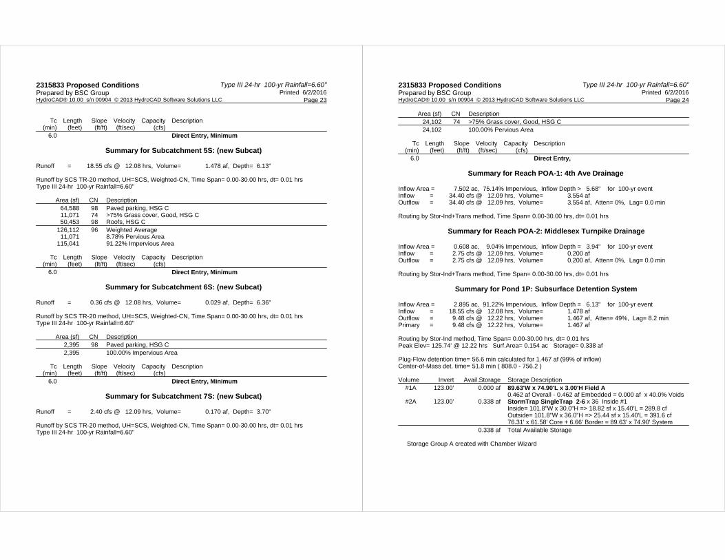
Type III 24-hr 100-yr Rainfall=6.60"2315833 Proposed Conditions Printed 6/2/2016Prepared by BSC Group
Page 23HydroCAD® 10.00 s/n 00904 © 2013 HydroCAD Software Solutions LLC
Tc Length Slope Velocity Capacity Description(min) (feet) (ft/ft) (ft/sec) (cfs)
6.0 Direct Entry, Minimum
Summary for Subcatchment 5S: (new Subcat)
Runoff = 18.55 cfs @ 12.08 hrs, Volume= 1.478 af, Depth= 6.13"
Runoff by SCS TR-20 method, UH=SCS, Weighted-CN, Time Span= 0.00-30.00 hrs, dt= 0.01 hrsType III 24-hr 100-yr Rainfall=6.60"
Area (sf) CN Description64,588 98 Paved parking, HSG C11,071 74 >75% Grass cover, Good, HSG C50,453 98 Roofs, HSG C
126,112 96 Weighted Average11,071 8.78% Pervious Area
115,041 91.22% Impervious Area
Tc Length Slope Velocity Capacity Description(min) (feet) (ft/ft) (ft/sec) (cfs)
6.0 Direct Entry, Minimum
Summary for Subcatchment 6S: (new Subcat)
Runoff = 0.36 cfs @ 12.08 hrs, Volume= 0.029 af, Depth= 6.36"
Runoff by SCS TR-20 method, UH=SCS, Weighted-CN, Time Span= 0.00-30.00 hrs, dt= 0.01 hrsType III 24-hr 100-yr Rainfall=6.60"
Area (sf) CN Description2,395 98 Paved parking, HSG C2,395 100.00% Impervious Area
Tc Length Slope Velocity Capacity Description(min) (feet) (ft/ft) (ft/sec) (cfs)
6.0 Direct Entry, Minimum
Summary for Subcatchment 7S: (new Subcat)
Runoff = 2.40 cfs @ 12.09 hrs, Volume= 0.170 af, Depth= 3.70"
Runoff by SCS TR-20 method, UH=SCS, Weighted-CN, Time Span= 0.00-30.00 hrs, dt= 0.01 hrsType III 24-hr 100-yr Rainfall=6.60"
Type III 24-hr 100-yr Rainfall=6.60"2315833 Proposed Conditions Printed 6/2/2016Prepared by BSC Group
Page 24HydroCAD® 10.00 s/n 00904 © 2013 HydroCAD Software Solutions LLC
Area (sf) CN Description24,102 74 >75% Grass cover, Good, HSG C24,102 100.00% Pervious Area
Tc Length Slope Velocity Capacity Description(min) (feet) (ft/ft) (ft/sec) (cfs)
6.0 Direct Entry,
Summary for Reach POA-1: 4th Ave Drainage
Inflow Area = 7.502 ac, 75.14% Impervious, Inflow Depth > 5.68" for 100-yr eventInflow = 34.40 cfs @ 12.09 hrs, Volume= 3.554 afOutflow = 34.40 cfs @ 12.09 hrs, Volume= 3.554 af, Atten= 0%, Lag= 0.0 min
Routing by Stor-Ind+Trans method, Time Span= 0.00-30.00 hrs, dt= 0.01 hrs
Summary for Reach POA-2: Middlesex Turnpike Drainage
Inflow Area = 0.608 ac, 9.04% Impervious, Inflow Depth = 3.94" for 100-yr eventInflow = 2.75 cfs @ 12.09 hrs, Volume= 0.200 afOutflow = 2.75 cfs @ 12.09 hrs, Volume= 0.200 af, Atten= 0%, Lag= 0.0 min
Routing by Stor-Ind+Trans method, Time Span= 0.00-30.00 hrs, dt= 0.01 hrs
Summary for Pond 1P: Subsurface Detention System
Inflow Area = 2.895 ac, 91.22% Impervious, Inflow Depth = 6.13" for 100-yr eventInflow = 18.55 cfs @ 12.08 hrs, Volume= 1.478 afOutflow = 9.48 cfs @ 12.22 hrs, Volume= 1.467 af, Atten= 49%, Lag= 8.2 minPrimary = 9.48 cfs @ 12.22 hrs, Volume= 1.467 af
Routing by Stor-Ind method, Time Span= 0.00-30.00 hrs, dt= 0.01 hrsPeak Elev= 125.74' @ 12.22 hrs Surf.Area= 0.154 ac Storage= 0.338 af
Plug-Flow detention time= 56.6 min calculated for 1.467 af (99% of inflow)Center-of-Mass det. time= 51.8 min ( 808.0 - 756.2 )
Volume Invert Avail.Storage Storage Description#1A 123.00' 0.000 af 89.63'W x 74.90'L x 3.00'H Field A
0.462 af Overall - 0.462 af Embedded = 0.000 af x 40.0% Voids#2A 123.00' 0.338 af StormTrap SingleTrap 2-6 x 36 Inside #1
Inside= 101.8"W x 30.0"H => 18.82 sf x 15.40'L = 289.8 cfOutside= 101.8"W x 36.0"H => 25.44 sf x 15.40'L = 391.6 cf76.31' x 61.58' Core + 6.66' Border = 89.63' x 74.90' System
0.338 af Total Available Storage
Storage Group A created with Chamber Wizard
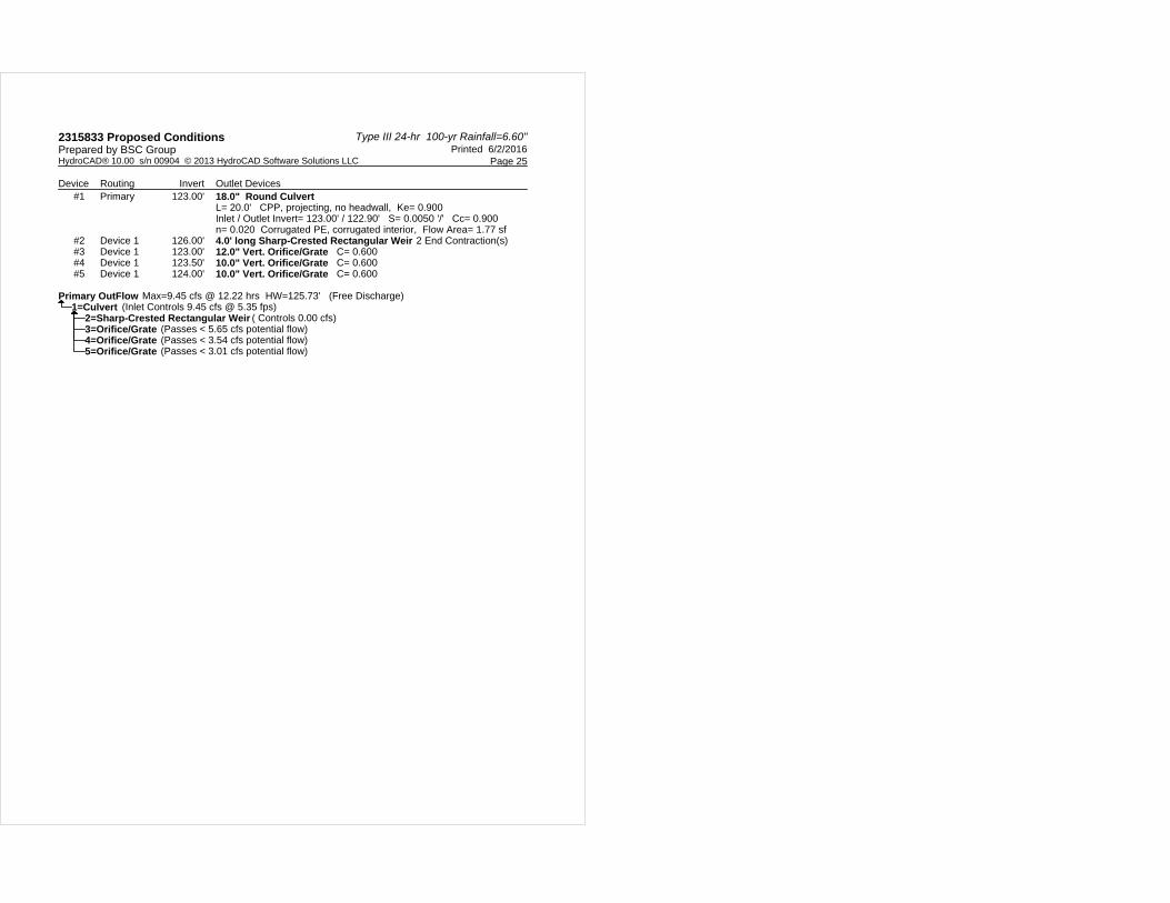
Type III 24-hr 100-yr Rainfall=6.60"2315833 Proposed Conditions Printed 6/2/2016Prepared by BSC Group
Page 25HydroCAD® 10.00 s/n 00904 © 2013 HydroCAD Software Solutions LLC
Device Routing Invert Outlet Devices#1 Primary 123.00' 18.0" Round Culvert
L= 20.0' CPP, projecting, no headwall, Ke= 0.900 Inlet / Outlet Invert= 123.00' / 122.90' S= 0.0050 '/' Cc= 0.900 n= 0.020 Corrugated PE, corrugated interior, Flow Area= 1.77 sf
#2 Device 1 126.00' 4.0' long Sharp-Crested Rectangular Weir 2 End Contraction(s) #3 Device 1 123.00' 12.0" Vert. Orifice/Grate C= 0.600 #4 Device 1 123.50' 10.0" Vert. Orifice/Grate C= 0.600 #5 Device 1 124.00' 10.0" Vert. Orifice/Grate C= 0.600
Primary OutFlow Max=9.45 cfs @ 12.22 hrs HW=125.73' (Free Discharge)1=Culvert (Inlet Controls 9.45 cfs @ 5.35 fps)
2=Sharp-Crested Rectangular Weir ( Controls 0.00 cfs)3=Orifice/Grate (Passes < 5.65 cfs potential flow)4=Orifice/Grate (Passes < 3.54 cfs potential flow)5=Orifice/Grate (Passes < 3.01 cfs potential flow)

Stormwater Report174/186 Middlesex Turnpike
Burlington, Massachusetts
SECTION 5.0
PIPE SIZING CALCULATIONS
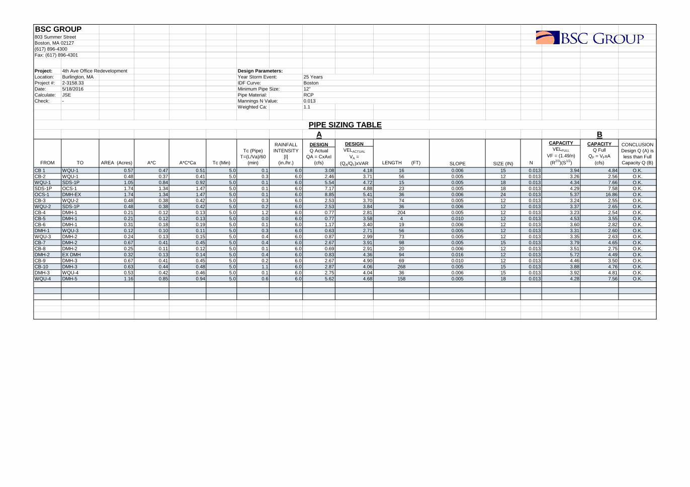
BSC GROUP803 Summer StreetBoston, MA 02127(617) 896-4300Fax: (617) 896-4301
Project: 4th Ave Office Redevelopment Design Parameters:Location: Burlington, MA Year Storm Event:Project #: 2-3158.33Date: 5/18/2016 Minimum Pipe Size:Calculate: JSE Pipe Material:Check: - Mannings N Value:
Weighted Ca: 1.1
A B
FROM TO AREA (Acres) A*C A*C*Ca Tc (Min)
Tc (Pipe) T=(L/Va)/60
(min)
RAINFALL INTENSITY
[I] (in./hr.)
DESIGN Q Actual
QA = CxAxI (cfs)
DESIGN VELACTUAL
VA = (QA/QF)xVAR LENGTH (FT) SLOPE SIZE (IN) N
CAPACITY VELFULL
VF = (1.49/n)
(R2/3)(S1/2)
CAPACITY Q Full
QF = VFxA (cfs)
CONCLUSION Design Q (A) is less than Full
Capacity Q (B)
CB 1 WQU-1 0.57 0.47 0.51 5.0 0.1 6.0 3.08 4.18 16 0.006 15 0.013 3.94 4.84 O.K.CB-2 WQU-1 0.48 0.37 0.41 5.0 0.3 6.0 2.46 3.71 56 0.005 12 0.013 3.26 2.56 O.K.WQU-1 SDS-1P 1.05 0.84 0.92 5.0 0.1 6.0 5.54 4.72 15 0.005 18 0.013 4.34 7.66 O.K.SDS-1P OCS-1 1.74 1.34 1.47 5.0 0.1 6.0 7.17 4.88 23 0.005 18 0.013 4.29 7.58 O.K.OCS-1 DMH-EX 1.74 1.34 1.47 5.0 0.1 6.0 8.85 5.41 36 0.006 24 0.013 5.37 16.86 O.K.CB-3 WQU-2 0.48 0.38 0.42 5.0 0.3 6.0 2.53 3.70 74 0.005 12 0.013 3.24 2.55 O.K.WQU-2 SDS-1P 0.48 0.38 0.42 5.0 0.2 6.0 2.53 3.84 36 0.006 12 0.013 3.37 2.65 O.K.CB-4 DMH-1 0.21 0.12 0.13 5.0 1.2 6.0 0.77 2.81 204 0.005 12 0.013 3.23 2.54 O.K.CB-5 DMH-1 0.21 0.12 0.13 5.0 0.0 6.0 0.77 3.58 4 0.010 12 0.013 4.53 3.55 O.K.CB-6 DMH-1 0.31 0.18 0.19 5.0 0.1 6.0 1.17 3.40 19 0.006 12 0.013 3.60 2.82 O.K.DMH-1 WQU-3 0.12 0.10 0.11 5.0 0.3 6.0 0.63 2.71 56 0.005 12 0.013 3.31 2.60 O.K.WQU-3 DMH-2 0.24 0.13 0.15 5.0 0.4 6.0 0.87 2.99 73 0.005 12 0.013 3.35 2.63 O.K.CB-7 DMH-2 0.67 0.41 0.45 5.0 0.4 6.0 2.67 3.91 98 0.005 15 0.013 3.79 4.65 O.K.CB-8 DMH-2 0.25 0.11 0.12 5.0 0.1 6.0 0.69 2.91 20 0.006 12 0.013 3.51 2.75 O.K.DMH-2 EX DMH 0.32 0.13 0.14 5.0 0.4 6.0 0.83 4.36 94 0.016 12 0.013 5.72 4.49 O.K.CB-9 DMH-3 0.67 0.41 0.45 5.0 0.2 6.0 2.67 4.90 69 0.010 12 0.013 4.46 3.50 O.K.CB-10 DMH-3 0.63 0.44 0.48 5.0 1.1 6.0 2.87 4.06 268 0.005 15 0.013 3.88 4.76 O.K.DMH-3 WQU-4 0.53 0.42 0.46 5.0 0.1 6.0 2.75 4.04 36 0.006 15 0.013 3.92 4.81 O.K.WQU-4 DMH-5 1.16 0.85 0.94 5.0 0.6 6.0 5.62 4.68 158 0.005 18 0.013 4.28 7.56 O.K.
25 Years
0.013
12"RCP
IDF Curve: Boston
PIPE SIZING TABLE
Stormwater Report174/186 Middlesex Turnpike
Burlington, Massachusetts
SECTION 6.0
ADDITIONAL DRAINAGE CALCULATIONS
6.01 STORAGE DRAWDOWN CALCULATIONS 6.02 WATER QUALITY UNIT SIZING INFORMATION
6.03 TSS REMOVAL CALCULATIONS 6.04 COMPENSATORY STORAGE ANALYSIS
Stormwater Report174/186 Middlesex Turnpike
Burlington, Massachusetts
6.01
STORAGE DRAWDOWN CALCULATIONS
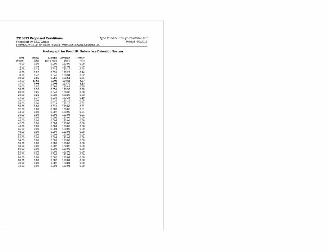
Type III 24-hr 100-yr Rainfall=6.60"2315833 Proposed Conditions Printed 6/2/2016Prepared by BSC Group
HydroCAD® 10.00 s/n 00904 © 2013 HydroCAD Software Solutions LLC
Hydrograph for Pond 1P: Subsurface Detention System
Time(hours)
Inflow(cfs)
Storage(acre-feet)
Elevation(feet)
Primary(cfs)
0.00 0.00 0.000 123.00 0.002.00 0.03 0.001 123.01 0.004.00 0.13 0.014 123.10 0.026.00 0.22 0.031 123.23 0.148.00 0.42 0.046 123.34 0.32
10.00 0.86 0.069 123.51 0.7112.00 11.65 0.205 124.51 4.9714.00 0.98 0.095 123.70 1.3316.00 0.52 0.066 123.49 0.6518.00 0.32 0.051 123.38 0.3920.00 0.25 0.043 123.32 0.2822.00 0.21 0.039 123.29 0.2324.00 0.17 0.036 123.26 0.1926.00 0.00 0.020 123.15 0.0528.00 0.00 0.014 123.10 0.0230.00 0.00 0.010 123.08 0.0132.00 0.00 0.009 123.06 0.0134.00 0.00 0.007 123.05 0.0136.00 0.00 0.006 123.05 0.0138.00 0.00 0.006 123.04 0.0040.00 0.00 0.005 123.04 0.0042.00 0.00 0.004 123.03 0.0044.00 0.00 0.004 123.03 0.0046.00 0.00 0.004 123.03 0.0048.00 0.00 0.004 123.03 0.0050.00 0.00 0.003 123.02 0.0052.00 0.00 0.003 123.02 0.0054.00 0.00 0.003 123.02 0.0056.00 0.00 0.003 123.02 0.0058.00 0.00 0.002 123.02 0.0060.00 0.00 0.002 123.02 0.0062.00 0.00 0.002 123.02 0.0064.00 0.00 0.002 123.01 0.0066.00 0.00 0.002 123.01 0.0068.00 0.00 0.002 123.01 0.0070.00 0.00 0.002 123.01 0.0072.00 0.00 0.001 123.01 0.00
Stormwater Report174/186 Middlesex Turnpike
Burlington, Massachusetts
6.02
WATER QUALITY UNIT SIZING INFORMATION
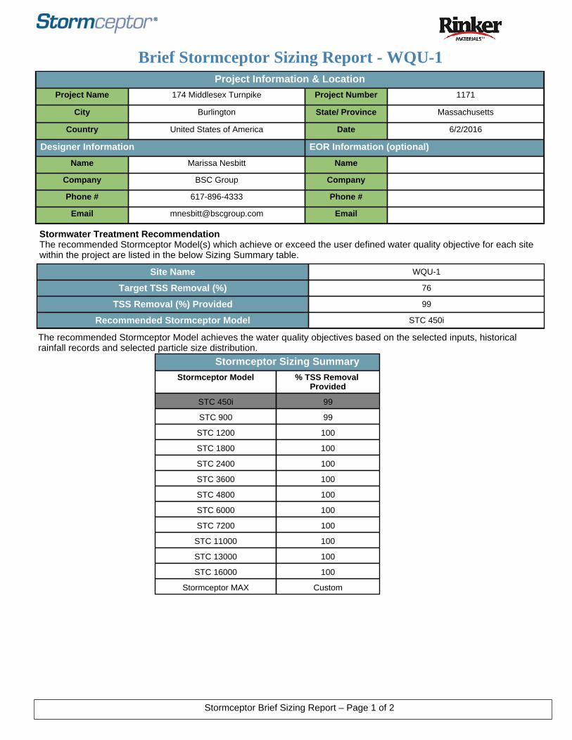
Project Information & LocationProject Name 174 Middlesex Turnpike Project Number 1171
City Burlington State/ Province Massachusetts
Country United States of America Date 6/2/2016
Designer Information EOR Information (optional)
Name Marissa Nesbitt Name
Company BSC Group Company
Phone # 617-896-4333 Phone #
Email [email protected] Email
Stormwater Treatment RecommendationThe recommended Stormceptor Model(s) which achieve or exceed the user defined water quality objective for each site within the project are listed in the below Sizing Summary table.
Brief Stormceptor Sizing Report - WQU-1
Site Name WQU-1
Target TSS Removal (%) 76
TSS Removal (%) Provided 99
Recommended Stormceptor Model STC 450i
Stormceptor Sizing SummaryStormceptor Model % TSS Removal
Provided
STC 450i 99
STC 900 99
STC 1200 100
STC 1800 100
STC 2400 100
STC 3600 100
STC 4800 100
STC 6000 100
STC 7200 100
STC 11000 100
STC 13000 100
STC 16000 100
Stormceptor MAX Custom
The recommended Stormceptor Model achieves the water quality objectives based on the selected inputs, historical rainfall records and selected particle size distribution.
Stormceptor Brief Sizing Report – Page 1 of 2
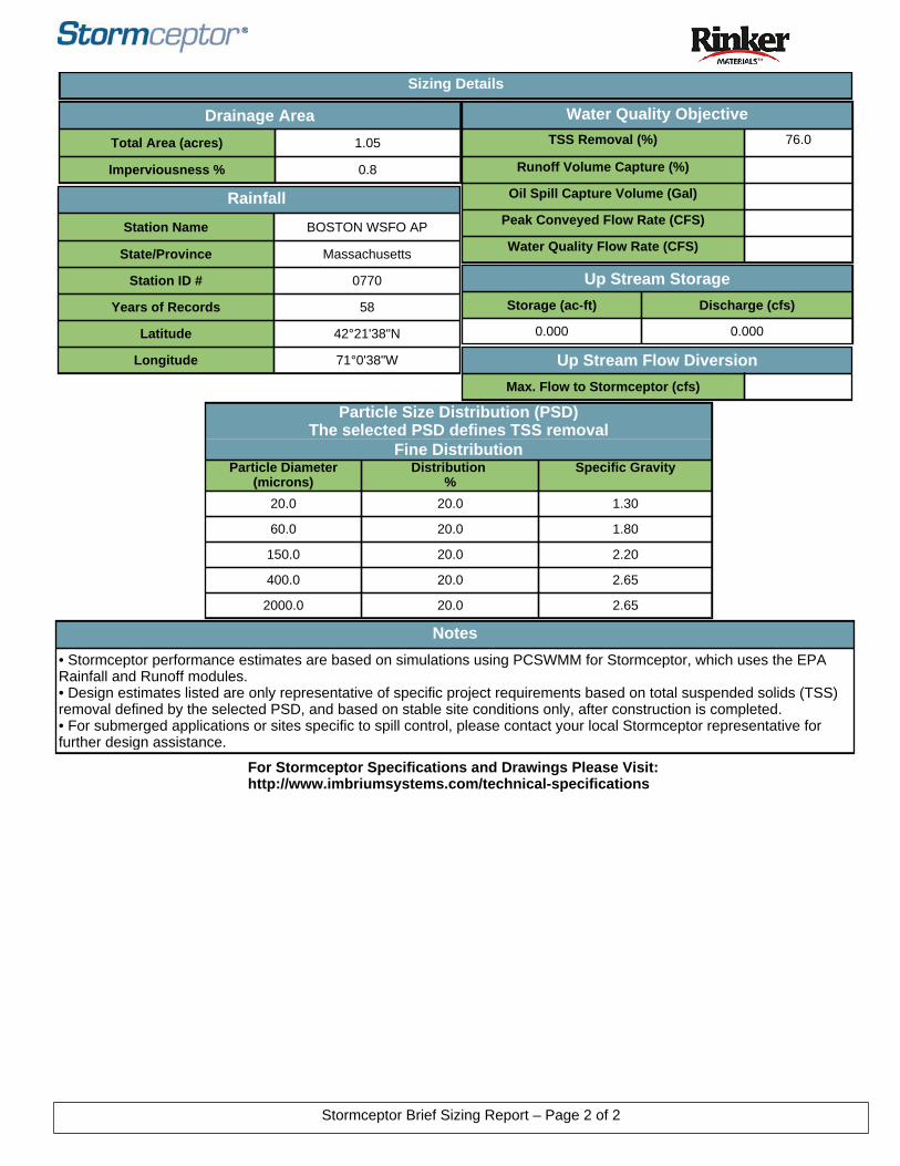
Notes
• Stormceptor performance estimates are based on simulations using PCSWMM for Stormceptor, which uses the EPA Rainfall and Runoff modules.• Design estimates listed are only representative of specific project requirements based on total suspended solids (TSS) removal defined by the selected PSD, and based on stable site conditions only, after construction is completed.• For submerged applications or sites specific to spill control, please contact your local Stormceptor representative for further design assistance.
Drainage Area
Total Area (acres) 1.05
Imperviousness % 0.8
Water Quality Objective
TSS Removal (%) 76.0
Runoff Volume Capture (%)
Oil Spill Capture Volume (Gal)
Peak Conveyed Flow Rate (CFS)
Water Quality Flow Rate (CFS)
Rainfall
Station Name BOSTON WSFO AP
State/Province Massachusetts
Station ID # 0770
Years of Records 58
Latitude 42°21'38"N
Longitude 71°0'38"W
Up Stream Storage
Storage (ac-ft) Discharge (cfs)
0.000 0.000
Particle Size Distribution (PSD)The selected PSD defines TSS removal
Fine DistributionParticle Diameter
(microns)Distribution
%Specific Gravity
20.0 20.0 1.30
60.0 20.0 1.80
150.0 20.0 2.20
400.0 20.0 2.65
2000.0 20.0 2.65
Up Stream Flow Diversion
Max. Flow to Stormceptor (cfs)
Sizing Details
For Stormceptor Specifications and Drawings Please Visit: http://www.imbriumsystems.com/technical-specifications
Stormceptor Brief Sizing Report – Page 2 of 2
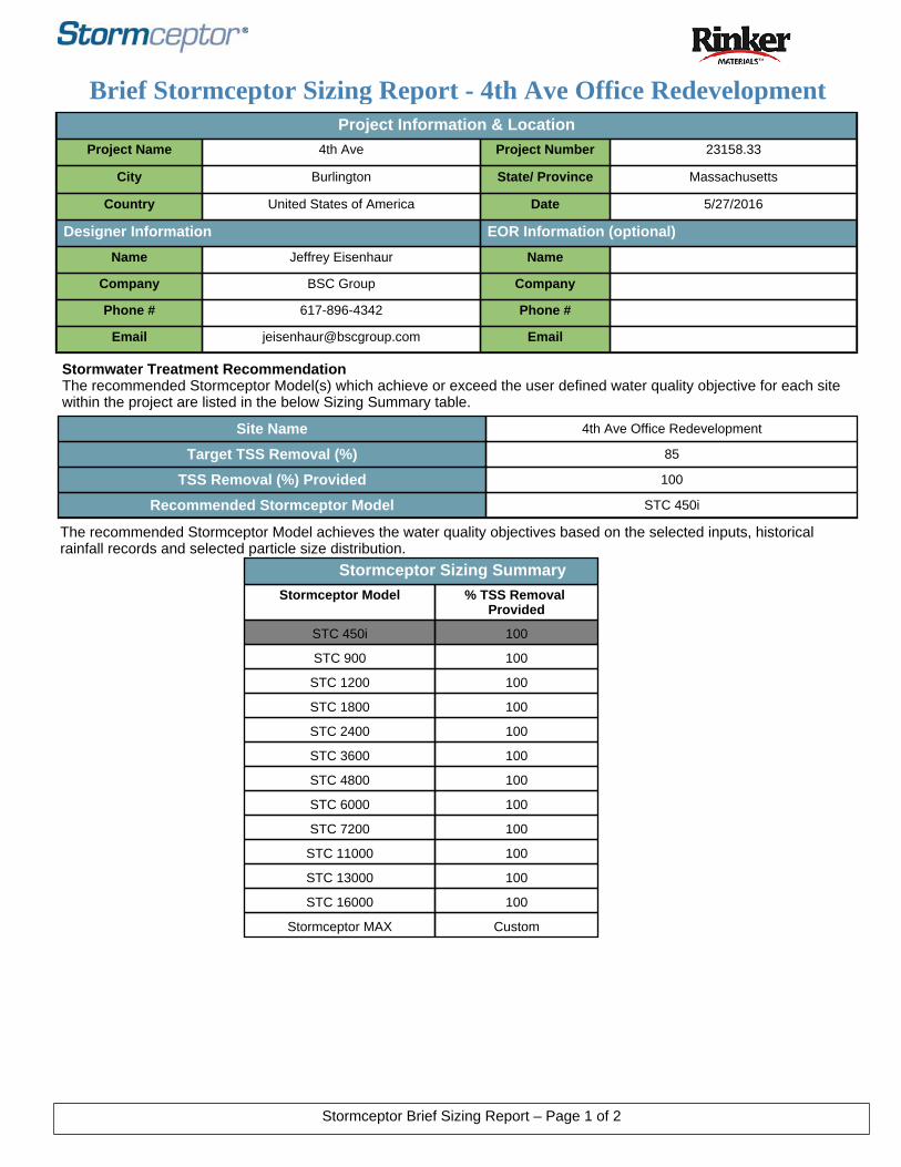
Project Information & LocationProject Name 4th Ave Project Number 23158.33
City Burlington State/ Province Massachusetts
Country United States of America Date 5/27/2016
Designer Information EOR Information (optional)
Name Jeffrey Eisenhaur Name
Company BSC Group Company
Phone # 617-896-4342 Phone #
Email [email protected] Email
Stormwater Treatment RecommendationThe recommended Stormceptor Model(s) which achieve or exceed the user defined water quality objective for each site within the project are listed in the below Sizing Summary table.
Brief Stormceptor Sizing Report - 4th Ave Office Redevelopment
Site Name 4th Ave Office Redevelopment
Target TSS Removal (%) 85
TSS Removal (%) Provided 100
Recommended Stormceptor Model STC 450i
Stormceptor Sizing SummaryStormceptor Model % TSS Removal
Provided
STC 450i 100
STC 900 100
STC 1200 100
STC 1800 100
STC 2400 100
STC 3600 100
STC 4800 100
STC 6000 100
STC 7200 100
STC 11000 100
STC 13000 100
STC 16000 100
Stormceptor MAX Custom
The recommended Stormceptor Model achieves the water quality objectives based on the selected inputs, historical rainfall records and selected particle size distribution.
Stormceptor Brief Sizing Report – Page 1 of 2

Notes
• Stormceptor performance estimates are based on simulations using PCSWMM for Stormceptor, which uses the EPA Rainfall and Runoff modules.• Design estimates listed are only representative of specific project requirements based on total suspended solids (TSS) removal defined by the selected PSD, and based on stable site conditions only, after construction is completed.• For submerged applications or sites specific to spill control, please contact your local Stormceptor representative for further design assistance.
Drainage Area
Total Area (acres) 0.21
Imperviousness % 0.0
Water Quality Objective
TSS Removal (%) 85.0
Runoff Volume Capture (%)
Oil Spill Capture Volume (Gal)
Peak Conveyed Flow Rate (CFS)
Water Quality Flow Rate (CFS)
Rainfall
Station Name BOSTON WSFO AP
State/Province Massachusetts
Station ID # 0770
Years of Records 58
Latitude 42°21'38"N
Longitude 71°0'38"W
Up Stream Storage
Storage (ac-ft) Discharge (cfs)
0.000 0.000
Particle Size Distribution (PSD)The selected PSD defines TSS removal
Fine DistributionParticle Diameter
(microns)Distribution
%Specific Gravity
20.0 20.0 1.30
60.0 20.0 1.80
150.0 20.0 2.20
400.0 20.0 2.65
2000.0 20.0 2.65
Up Stream Flow Diversion
Max. Flow to Stormceptor (cfs)
Sizing Details
For Stormceptor Specifications and Drawings Please Visit: http://www.imbriumsystems.com/technical-specifications
Stormceptor Brief Sizing Report – Page 2 of 2

Project Information & LocationProject Name 174 Middlesex Turnpike Project Number 1171
City Burlington State/ Province Massachusetts
Country United States of America Date 6/2/2016
Designer Information EOR Information (optional)
Name Marissa Nesbitt Name
Company BSC Group Company
Phone # 617-896-4333 Phone #
Email [email protected] Email
Stormwater Treatment RecommendationThe recommended Stormceptor Model(s) which achieve or exceed the user defined water quality objective for each site within the project are listed in the below Sizing Summary table.
Brief Stormceptor Sizing Report - WQU-3
Site Name WQU-3
Target TSS Removal (%) 76
TSS Removal (%) Provided 81
Recommended Stormceptor Model STC 450i
Stormceptor Sizing SummaryStormceptor Model % TSS Removal
Provided
STC 450i 81
STC 900 86
STC 1200 86
STC 1800 87
STC 2400 89
STC 3600 90
STC 4800 92
STC 6000 92
STC 7200 93
STC 11000 95
STC 13000 95
STC 16000 96
Stormceptor MAX Custom
The recommended Stormceptor Model achieves the water quality objectives based on the selected inputs, historical rainfall records and selected particle size distribution.
Stormceptor Brief Sizing Report – Page 1 of 2

Notes
• Stormceptor performance estimates are based on simulations using PCSWMM for Stormceptor, which uses the EPA Rainfall and Runoff modules.• Design estimates listed are only representative of specific project requirements based on total suspended solids (TSS) removal defined by the selected PSD, and based on stable site conditions only, after construction is completed.• For submerged applications or sites specific to spill control, please contact your local Stormceptor representative for further design assistance.
Drainage Area
Total Area (acres) 0.48
Imperviousness % 85.0
Water Quality Objective
TSS Removal (%) 76.0
Runoff Volume Capture (%)
Oil Spill Capture Volume (Gal)
Peak Conveyed Flow Rate (CFS)
Water Quality Flow Rate (CFS)
Rainfall
Station Name BOSTON WSFO AP
State/Province Massachusetts
Station ID # 0770
Years of Records 58
Latitude 42°21'38"N
Longitude 71°0'38"W
Up Stream Storage
Storage (ac-ft) Discharge (cfs)
0.000 0.000
Particle Size Distribution (PSD)The selected PSD defines TSS removal
Fine DistributionParticle Diameter
(microns)Distribution
%Specific Gravity
20.0 20.0 1.30
60.0 20.0 1.80
150.0 20.0 2.20
400.0 20.0 2.65
2000.0 20.0 2.65
Up Stream Flow Diversion
Max. Flow to Stormceptor (cfs)
Sizing Details
For Stormceptor Specifications and Drawings Please Visit: http://www.imbriumsystems.com/technical-specifications
Stormceptor Brief Sizing Report – Page 2 of 2
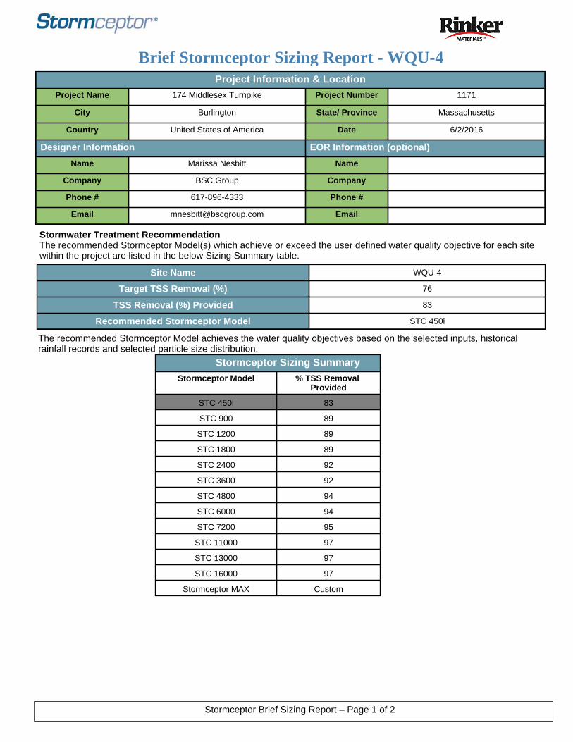
Project Information & LocationProject Name 174 Middlesex Turnpike Project Number 1171
City Burlington State/ Province Massachusetts
Country United States of America Date 6/2/2016
Designer Information EOR Information (optional)
Name Marissa Nesbitt Name
Company BSC Group Company
Phone # 617-896-4333 Phone #
Email [email protected] Email
Stormwater Treatment RecommendationThe recommended Stormceptor Model(s) which achieve or exceed the user defined water quality objective for each site within the project are listed in the below Sizing Summary table.
Brief Stormceptor Sizing Report - WQU-4
Site Name WQU-4
Target TSS Removal (%) 76
TSS Removal (%) Provided 83
Recommended Stormceptor Model STC 450i
Stormceptor Sizing SummaryStormceptor Model % TSS Removal
Provided
STC 450i 83
STC 900 89
STC 1200 89
STC 1800 89
STC 2400 92
STC 3600 92
STC 4800 94
STC 6000 94
STC 7200 95
STC 11000 97
STC 13000 97
STC 16000 97
Stormceptor MAX Custom
The recommended Stormceptor Model achieves the water quality objectives based on the selected inputs, historical rainfall records and selected particle size distribution.
Stormceptor Brief Sizing Report – Page 1 of 2

Notes
• Stormceptor performance estimates are based on simulations using PCSWMM for Stormceptor, which uses the EPA Rainfall and Runoff modules.• Design estimates listed are only representative of specific project requirements based on total suspended solids (TSS) removal defined by the selected PSD, and based on stable site conditions only, after construction is completed.• For submerged applications or sites specific to spill control, please contact your local Stormceptor representative for further design assistance.
Drainage Area
Total Area (acres) 0.68
Imperviousness % 85.0
Water Quality Objective
TSS Removal (%) 76.0
Runoff Volume Capture (%)
Oil Spill Capture Volume (Gal)
Peak Conveyed Flow Rate (CFS)
Water Quality Flow Rate (CFS)
Rainfall
Station Name BOSTON WSFO AP
State/Province Massachusetts
Station ID # 0770
Years of Records 58
Latitude 42°21'38"N
Longitude 71°0'38"W
Up Stream Storage
Storage (ac-ft) Discharge (cfs)
0.000 0.000
Particle Size Distribution (PSD)The selected PSD defines TSS removal
Fine DistributionParticle Diameter
(microns)Distribution
%Specific Gravity
20.0 20.0 1.30
60.0 20.0 1.80
150.0 20.0 2.20
400.0 20.0 2.65
2000.0 20.0 2.65
Up Stream Flow Diversion
Max. Flow to Stormceptor (cfs)
Sizing Details
For Stormceptor Specifications and Drawings Please Visit: http://www.imbriumsystems.com/technical-specifications
Stormceptor Brief Sizing Report – Page 2 of 2
Stormwater Report174/186 Middlesex Turnpike
Burlington, Massachusetts
6.03
TSS REMOVAL CALCULATIONS
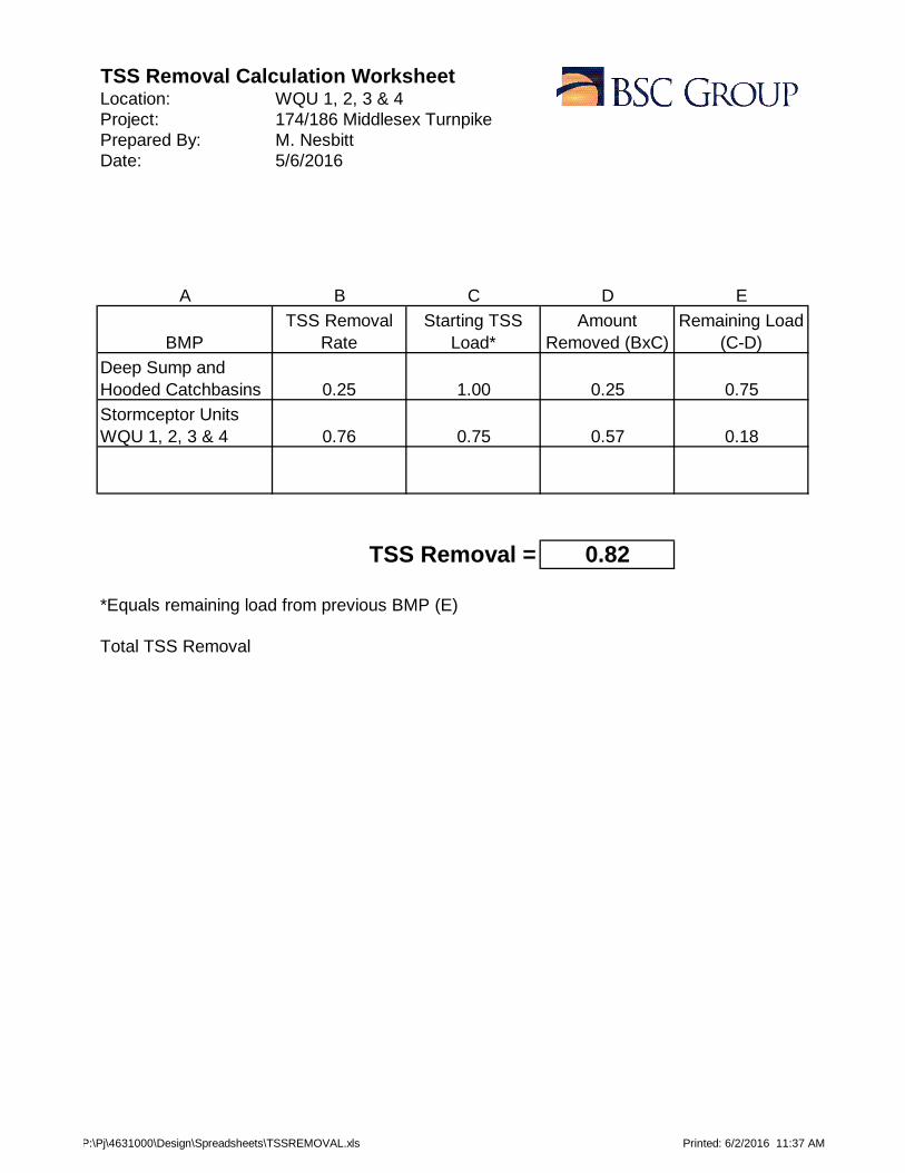
TSS Removal Calculation WorksheetLocation: WQU 1, 2, 3 & 4Project: 174/186 Middlesex TurnpikePrepared By: M. NesbittDate: 5/6/2016
A B C D E
BMPTSS Removal
RateStarting TSS
Load*Amount
Removed (BxC)Remaining Load
(C-D)
Deep Sump and Hooded Catchbasins 0.25 1.00 0.25 0.75
Stormceptor Units WQU 1, 2, 3 & 4 0.76 0.75 0.57 0.18
TSS Removal = 0.82
*Equals remaining load from previous BMP (E)
Total TSS Removal
P:\Pj\4631000\Design\Spreadsheets\TSSREMOVAL.xls Printed: 6/2/2016 11:37 AM
Stormwater Report174/186 Middlesex Turnpike
Burlington, Massachusetts
6.04
COMPENSATORY STORAGE ANALYSIS
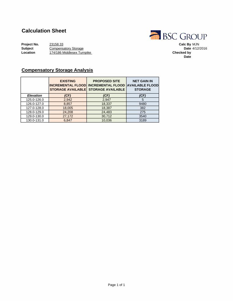
Calculation Sheet
Project No. 23158.33 Calc By MJNSubject Compensatory Storage Date 4/12/2016Location 174/186 Middlesex Turnpike Checked by
Date
Compensatory Storage Analysis
EXISTING INCREMENTAL FLOOD STORAGE AVAILABLE
PROPOSED SITE INCREMENTAL FLOOD STORAGE AVAILABLE
NET GAIN IN AVAILABLE FLOOD
STORAGE
Elevation (CF) (CF) (CF)125.0-126.0 2,942 2,947 5126.0-127.0 8,857 18,337 9480127.0-128.0 18,005 18,387 382128.0-129.0 24,208 24,483 275129.0-130.0 27,172 30,712 3540130.0-131.0 6,847 10,036 3189
Page 1 of 1
Stormwater Report174/186 Middlesex Turnpike
Burlington, Massachusetts
APPENDICES
Stormwater Report174/186 Middlesex Turnpike
Burlington, Massachusetts
ORDER OF RESOURCE AREA DELINEATION
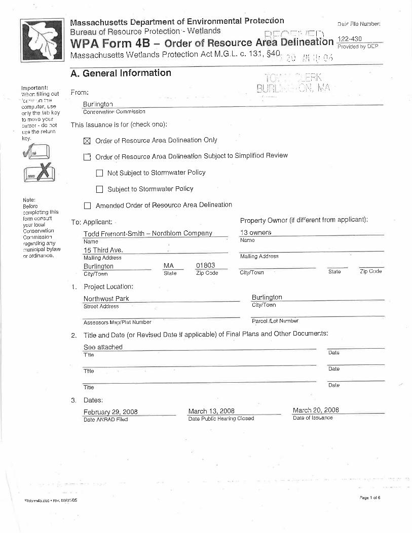
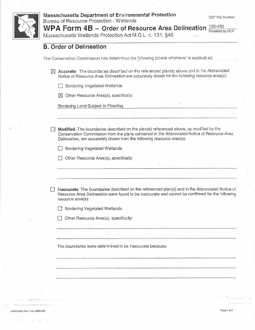
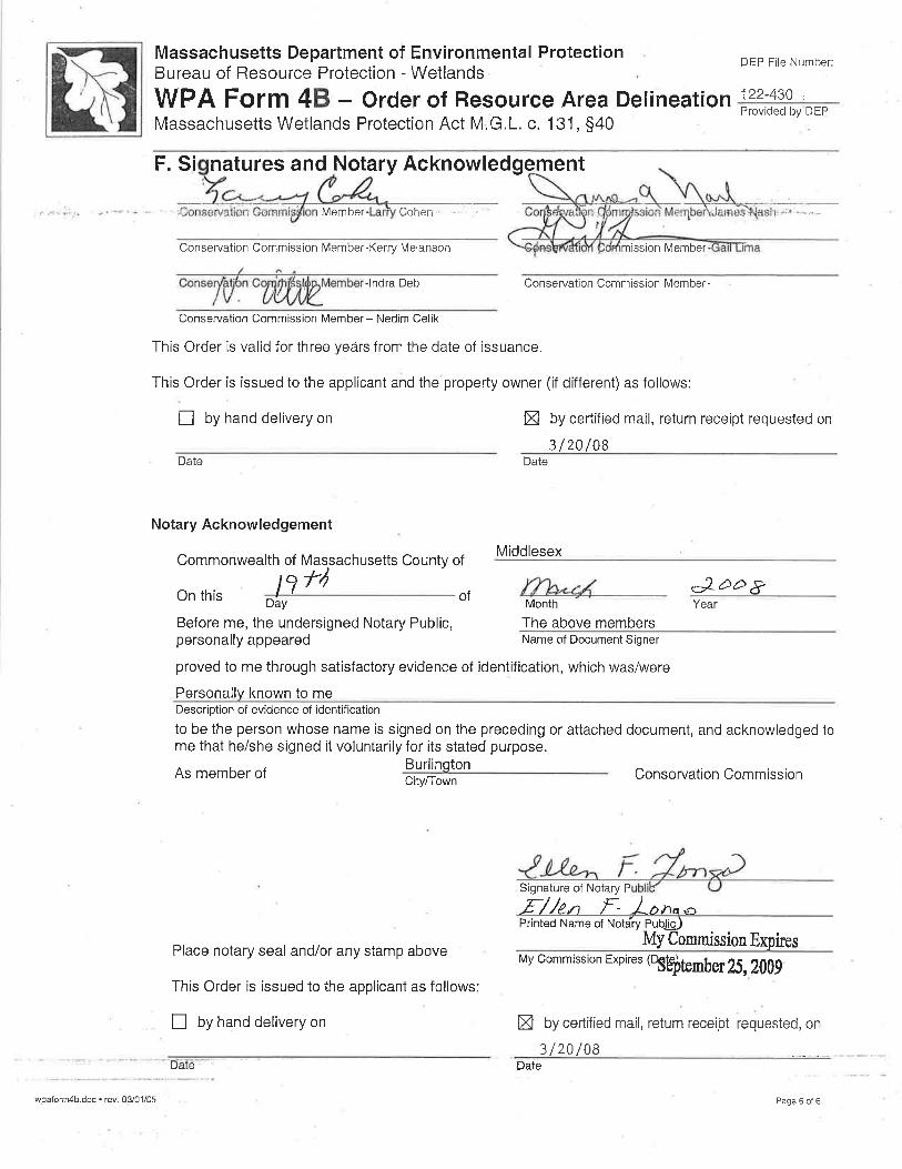
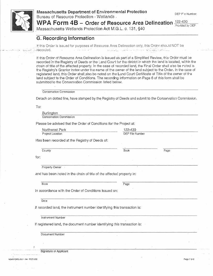
Stormwater Report174/186 Middlesex Turnpike
Burlington, Massachusetts
SOIL SURVEY MAP
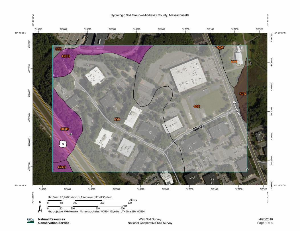
Hydrologic Soil Group—Middlesex County, Massachusetts
Natural ResourcesConservation Service
Web Soil SurveyNational Cooperative Soil Survey
4/28/2016Page 1 of 4
4706
560
4706
650
4706
740
4706
830
4706
920
4707
010
4706
470
4706
560
4706
650
4706
740
4706
830
4706
920
4707
010
316510 316600 316690 316780 316870 316960 317050 317140 317230 317320
316510 316600 316690 316780 316870 316960 317050 317140 317230 317320
42° 29' 38'' N71
° 1
3' 5
9'' W
42° 29' 38'' N
71° 1
3' 2
1'' W
42° 29' 20'' N
71° 1
3' 5
9'' W
42° 29' 20'' N
71° 1
3' 2
1'' W
N
Map projection: Web Mercator Corner coordinates: WGS84 Edge tics: UTM Zone 19N WGS840 150 300 600 900
Feet0 50 100 200 300
MetersMap Scale: 1:3,940 if printed on A landscape (11" x 8.5") sheet.
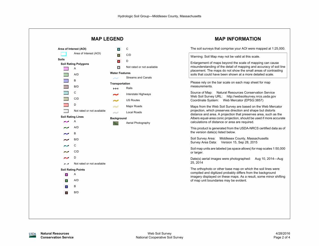
MAP LEGEND MAP INFORMATION
Area of Interest (AOI)Area of Interest (AOI)
SoilsSoil Rating Polygons
A
A/D
B
B/D
C
C/D
D
Not rated or not available
Soil Rating LinesA
A/D
B
B/D
C
C/D
D
Not rated or not available
Soil Rating PointsA
A/D
B
B/D
C
C/D
D
Not rated or not available
Water FeaturesStreams and Canals
TransportationRails
Interstate Highways
US Routes
Major Roads
Local Roads
BackgroundAerial Photography
The soil surveys that comprise your AOI were mapped at 1:25,000.
Warning: Soil Map may not be valid at this scale.
Enlargement of maps beyond the scale of mapping can causemisunderstanding of the detail of mapping and accuracy of soil lineplacement. The maps do not show the small areas of contrastingsoils that could have been shown at a more detailed scale.
Please rely on the bar scale on each map sheet for mapmeasurements.
Source of Map: Natural Resources Conservation ServiceWeb Soil Survey URL: http://websoilsurvey.nrcs.usda.govCoordinate System: Web Mercator (EPSG:3857)
Maps from the Web Soil Survey are based on the Web Mercatorprojection, which preserves direction and shape but distortsdistance and area. A projection that preserves area, such as theAlbers equal-area conic projection, should be used if more accuratecalculations of distance or area are required.
This product is generated from the USDA-NRCS certified data as ofthe version date(s) listed below.
Soil Survey Area: Middlesex County, MassachusettsSurvey Area Data: Version 15, Sep 28, 2015
Soil map units are labeled (as space allows) for map scales 1:50,000or larger.
Date(s) aerial images were photographed: Aug 10, 2014—Aug25, 2014
The orthophoto or other base map on which the soil lines werecompiled and digitized probably differs from the backgroundimagery displayed on these maps. As a result, some minor shiftingof map unit boundaries may be evident.
Hydrologic Soil Group—Middlesex County, Massachusetts
Natural ResourcesConservation Service
Web Soil SurveyNational Cooperative Soil Survey
4/28/2016Page 2 of 4
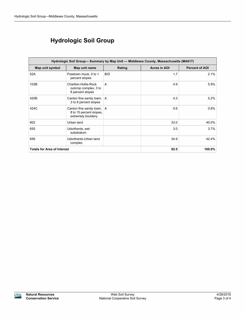
Hydrologic Soil Group
Hydrologic Soil Group— Summary by Map Unit — Middlesex County, Massachusetts (MA017)
Map unit symbol Map unit name Rating Acres in AOI Percent of AOI
52A Freetown muck, 0 to 1percent slopes
B/D 1.7 2.1%
103B Charlton-Hollis-Rockoutcrop complex, 3 to8 percent slopes
A 4.9 5.9%
420B Canton fine sandy loam,3 to 8 percent slopes
A 4.3 5.2%
424C Canton fine sandy loam,8 to 15 percent slopes,extremely bouldery
A 0.6 0.8%
602 Urban land 33.0 40.0%
655 Udorthents, wetsubstratum
3.0 3.7%
656 Udorthents-Urban landcomplex
34.9 42.4%
Totals for Area of Interest 82.5 100.0%
Hydrologic Soil Group—Middlesex County, Massachusetts
Natural ResourcesConservation Service
Web Soil SurveyNational Cooperative Soil Survey
4/28/2016Page 3 of 4
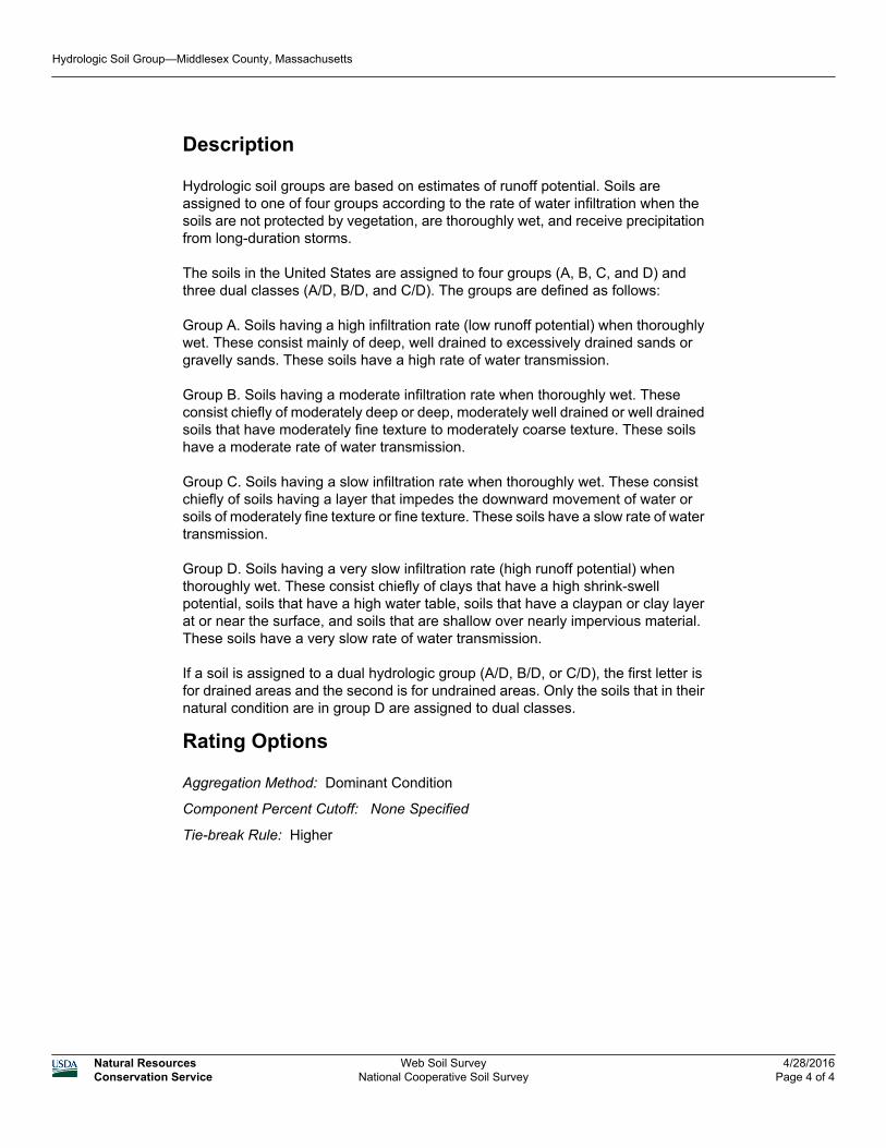
Description
Hydrologic soil groups are based on estimates of runoff potential. Soils areassigned to one of four groups according to the rate of water infiltration when thesoils are not protected by vegetation, are thoroughly wet, and receive precipitationfrom long-duration storms.
The soils in the United States are assigned to four groups (A, B, C, and D) andthree dual classes (A/D, B/D, and C/D). The groups are defined as follows:
Group A. Soils having a high infiltration rate (low runoff potential) when thoroughlywet. These consist mainly of deep, well drained to excessively drained sands orgravelly sands. These soils have a high rate of water transmission.
Group B. Soils having a moderate infiltration rate when thoroughly wet. Theseconsist chiefly of moderately deep or deep, moderately well drained or well drainedsoils that have moderately fine texture to moderately coarse texture. These soilshave a moderate rate of water transmission.
Group C. Soils having a slow infiltration rate when thoroughly wet. These consistchiefly of soils having a layer that impedes the downward movement of water orsoils of moderately fine texture or fine texture. These soils have a slow rate of watertransmission.
Group D. Soils having a very slow infiltration rate (high runoff potential) whenthoroughly wet. These consist chiefly of clays that have a high shrink-swellpotential, soils that have a high water table, soils that have a claypan or clay layerat or near the surface, and soils that are shallow over nearly impervious material.These soils have a very slow rate of water transmission.
If a soil is assigned to a dual hydrologic group (A/D, B/D, or C/D), the first letter isfor drained areas and the second is for undrained areas. Only the soils that in theirnatural condition are in group D are assigned to dual classes.
Rating Options
Aggregation Method: Dominant Condition
Component Percent Cutoff: None Specified
Tie-break Rule: Higher
Hydrologic Soil Group—Middlesex County, Massachusetts
Natural ResourcesConservation Service
Web Soil SurveyNational Cooperative Soil Survey
4/28/2016Page 4 of 4
Stormwater Report174/186 Middlesex Turnpike
Burlington, Massachusetts
STORMWATER REPORT CHECKLIST

swcheck.docx • 04/01/08 Stormwater Report Checklist • Page 1 of 8
Massachusetts Department of Environmental Protection Bureau of Resource Protection - Wetlands Program
Checklist for Stormwater Report
A. Introduction Important: When filling out forms on the computer, use only the tab key to move your cursor - do not use the return key.
A Stormwater Report must be submitted with the Notice of Intent permit application to document compliance with the Stormwater Management Standards. The following checklist is NOT a substitute for the Stormwater Report (which should provide more substantive and detailed information) but is offered here as a tool to help the applicant organize their Stormwater Management documentation for their Report and for the reviewer to assess this information in a consistent format. As noted in the Checklist, the Stormwater Report must contain the engineering computations and supporting information set forth in Volume 3 of the Massachusetts Stormwater Handbook. The Stormwater Report must be prepared and certified by a Registered Professional Engineer (RPE) licensed in the Commonwealth. The Stormwater Report must include:
The Stormwater Checklist completed and stamped by a Registered Professional Engineer (see page 2) that certifies that the Stormwater Report contains all required submittals.1 This Checklist is to be used as the cover for the completed Stormwater Report.
Applicant/Project Name Project Address Name of Firm and Registered Professional Engineer that prepared the Report Long-Term Pollution Prevention Plan required by Standards 4-6 Construction Period Pollution Prevention and Erosion and Sedimentation Control Plan required
by Standard 82 Operation and Maintenance Plan required by Standard 9
In addition to all plans and supporting information, the Stormwater Report must include a brief narrative describing stormwater management practices, including environmentally sensitive site design and LID techniques, along with a diagram depicting runoff through the proposed BMP treatment train. Plans are required to show existing and proposed conditions, identify all wetland resource areas, NRCS soil types, critical areas, Land Uses with Higher Potential Pollutant Loads (LUHPPL), and any areas on the site where infiltration rate is greater than 2.4 inches per hour. The Plans shall identify the drainage areas for both existing and proposed conditions at a scale that enables verification of supporting calculations.
As noted in the Checklist, the Stormwater Management Report shall document compliance with each of the Stormwater Management Standards as provided in the Massachusetts Stormwater Handbook. The soils evaluation and calculations shall be done using the methodologies set forth in Volume 3 of the Massachusetts Stormwater Handbook. To ensure that the Stormwater Report is complete, applicants are required to fill in the Stormwater Report Checklist by checking the box to indicate that the specified information has been included in the Stormwater Report. If any of the information specified in the checklist has not been submitted, the applicant must provide an explanation. The completed Stormwater Report Checklist and Certification must be submitted with the Stormwater Report.
1 The Stormwater Report may also include the Illicit Discharge Compliance Statement required by Standard 10. If not included in the Stormwater Report, the Illicit Discharge Compliance Statement must be submitted prior to the discharge of stormwater runoff to the post-construction best management practices. 2 For some complex projects, it may not be possible to include the Construction Period Erosion and Sedimentation Control Plan in the Stormwater Report. In that event, the issuing authority has the discretion to issue an Order of Conditions that approves the project and includes a condition requiring the proponent to submit the Construction Period Erosion and Sedimentation Control Plan before commencing any land disturbance activity on the site.
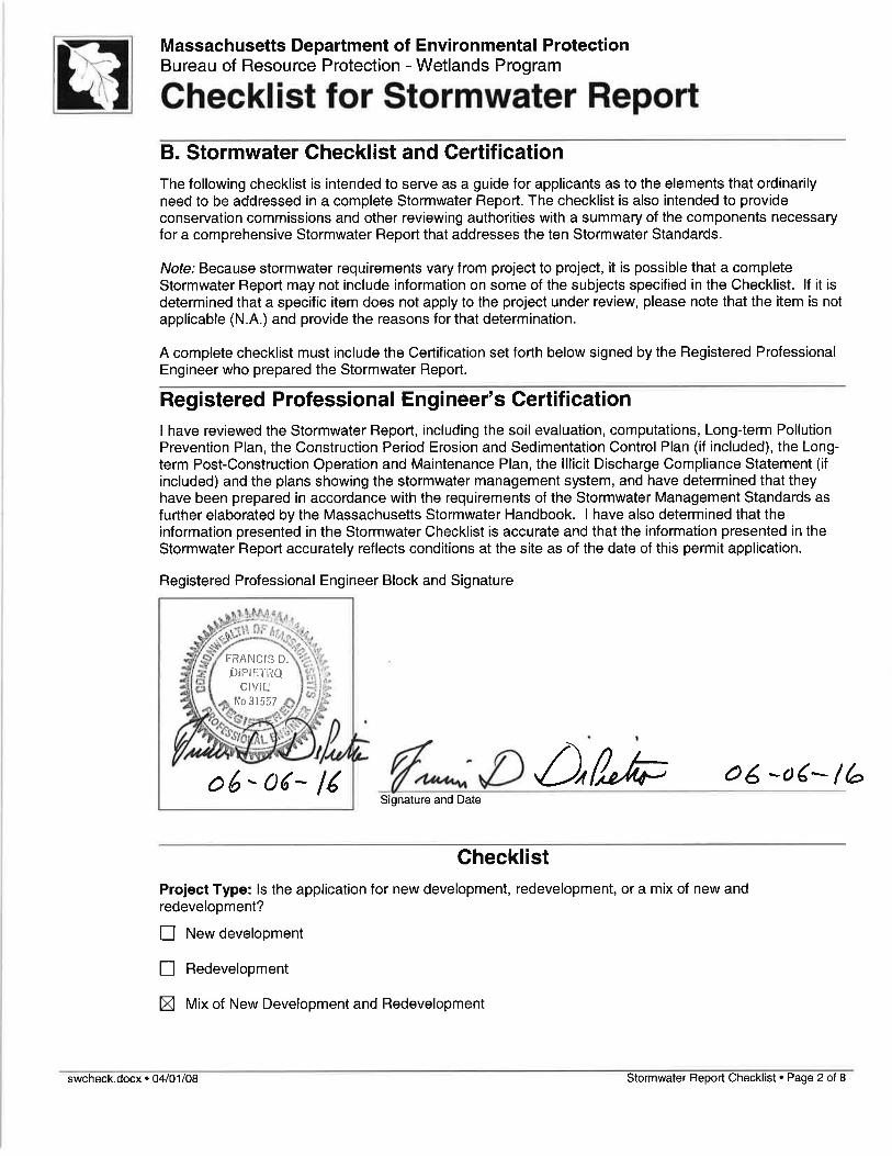
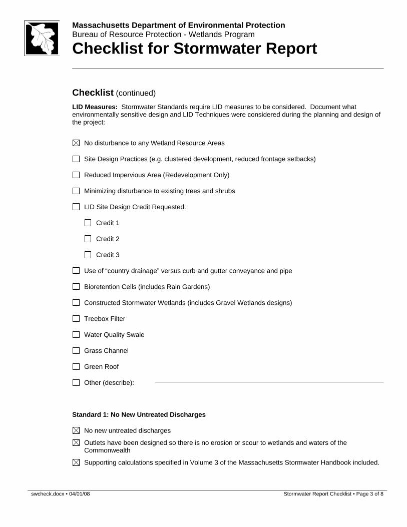
swcheck.docx • 04/01/08 Stormwater Report Checklist • Page 3 of 8
Massachusetts Department of Environmental Protection Bureau of Resource Protection - Wetlands Program
Checklist for Stormwater Report
Checklist (continued) LID Measures: Stormwater Standards require LID measures to be considered. Document what
environmentally sensitive design and LID Techniques were considered during the planning and design of the project:
No disturbance to any Wetland Resource Areas
Site Design Practices (e.g. clustered development, reduced frontage setbacks)
Reduced Impervious Area (Redevelopment Only)
Minimizing disturbance to existing trees and shrubs
LID Site Design Credit Requested:
Credit 1
Credit 2
Credit 3
Use of “country drainage” versus curb and gutter conveyance and pipe
Bioretention Cells (includes Rain Gardens)
Constructed Stormwater Wetlands (includes Gravel Wetlands designs)
Treebox Filter
Water Quality Swale
Grass Channel
Green Roof
Other (describe):
Standard 1: No New Untreated Discharges
No new untreated discharges
Outlets have been designed so there is no erosion or scour to wetlands and waters of the Commonwealth
Supporting calculations specified in Volume 3 of the Massachusetts Stormwater Handbook included.
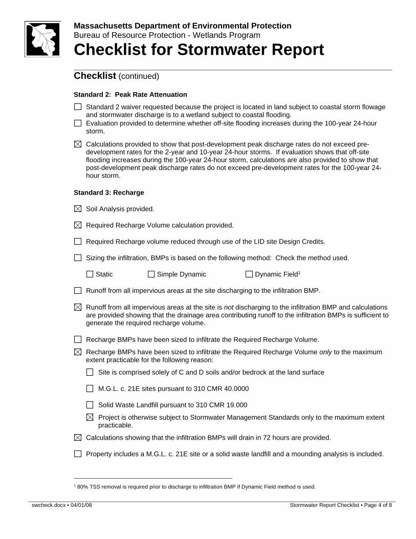
swcheck.docx • 04/01/08 Stormwater Report Checklist • Page 4 of 8
Massachusetts Department of Environmental Protection Bureau of Resource Protection - Wetlands Program
Checklist for Stormwater Report
Checklist (continued)
Standard 2: Peak Rate Attenuation
Standard 2 waiver requested because the project is located in land subject to coastal storm flowage and stormwater discharge is to a wetland subject to coastal flooding.
Evaluation provided to determine whether off-site flooding increases during the 100-year 24-hour storm.
Calculations provided to show that post-development peak discharge rates do not exceed pre-
development rates for the 2-year and 10-year 24-hour storms. If evaluation shows that off-site flooding increases during the 100-year 24-hour storm, calculations are also provided to show that post-development peak discharge rates do not exceed pre-development rates for the 100-year 24-hour storm.
Standard 3: Recharge
Soil Analysis provided.
Required Recharge Volume calculation provided.
Required Recharge volume reduced through use of the LID site Design Credits.
Sizing the infiltration, BMPs is based on the following method: Check the method used.
Static Simple Dynamic Dynamic Field1
Runoff from all impervious areas at the site discharging to the infiltration BMP.
Runoff from all impervious areas at the site is not discharging to the infiltration BMP and calculations
are provided showing that the drainage area contributing runoff to the infiltration BMPs is sufficient to generate the required recharge volume.
Recharge BMPs have been sized to infiltrate the Required Recharge Volume.
Recharge BMPs have been sized to infiltrate the Required Recharge Volume only to the maximum extent practicable for the following reason:
Site is comprised solely of C and D soils and/or bedrock at the land surface
M.G.L. c. 21E sites pursuant to 310 CMR 40.0000
Solid Waste Landfill pursuant to 310 CMR 19.000
Project is otherwise subject to Stormwater Management Standards only to the maximum extent practicable.
Calculations showing that the infiltration BMPs will drain in 72 hours are provided.
Property includes a M.G.L. c. 21E site or a solid waste landfill and a mounding analysis is included.
1 80% TSS removal is required prior to discharge to infiltration BMP if Dynamic Field method is used.
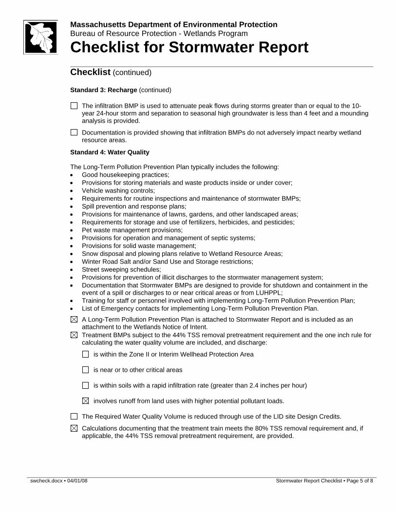
swcheck.docx • 04/01/08 Stormwater Report Checklist • Page 5 of 8
Massachusetts Department of Environmental Protection Bureau of Resource Protection - Wetlands Program
Checklist for Stormwater Report
Checklist (continued)
Standard 3: Recharge (continued)
The infiltration BMP is used to attenuate peak flows during storms greater than or equal to the 10-
year 24-hour storm and separation to seasonal high groundwater is less than 4 feet and a mounding analysis is provided.
Documentation is provided showing that infiltration BMPs do not adversely impact nearby wetland resource areas.
Standard 4: Water Quality
The Long-Term Pollution Prevention Plan typically includes the following: Good housekeeping practices; Provisions for storing materials and waste products inside or under cover; Vehicle washing controls; Requirements for routine inspections and maintenance of stormwater BMPs; Spill prevention and response plans; Provisions for maintenance of lawns, gardens, and other landscaped areas; Requirements for storage and use of fertilizers, herbicides, and pesticides; Pet waste management provisions; Provisions for operation and management of septic systems; Provisions for solid waste management; Snow disposal and plowing plans relative to Wetland Resource Areas; Winter Road Salt and/or Sand Use and Storage restrictions; Street sweeping schedules; Provisions for prevention of illicit discharges to the stormwater management system; Documentation that Stormwater BMPs are designed to provide for shutdown and containment in the
event of a spill or discharges to or near critical areas or from LUHPPL; Training for staff or personnel involved with implementing Long-Term Pollution Prevention Plan; List of Emergency contacts for implementing Long-Term Pollution Prevention Plan.
A Long-Term Pollution Prevention Plan is attached to Stormwater Report and is included as an attachment to the Wetlands Notice of Intent.
Treatment BMPs subject to the 44% TSS removal pretreatment requirement and the one inch rule for calculating the water quality volume are included, and discharge:
is within the Zone II or Interim Wellhead Protection Area
is near or to other critical areas
is within soils with a rapid infiltration rate (greater than 2.4 inches per hour)
involves runoff from land uses with higher potential pollutant loads.
The Required Water Quality Volume is reduced through use of the LID site Design Credits.
Calculations documenting that the treatment train meets the 80% TSS removal requirement and, if applicable, the 44% TSS removal pretreatment requirement, are provided.
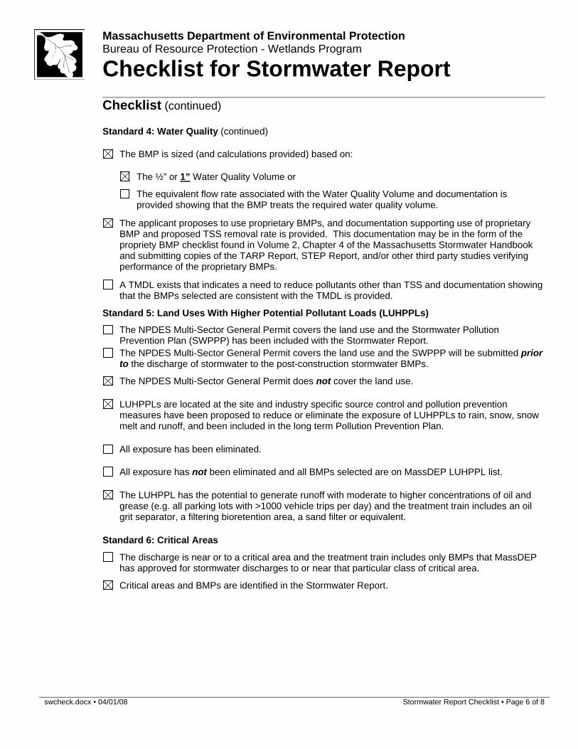
swcheck.docx • 04/01/08 Stormwater Report Checklist • Page 6 of 8
Massachusetts Department of Environmental Protection Bureau of Resource Protection - Wetlands Program
Checklist for Stormwater Report
Checklist (continued)
Standard 4: Water Quality (continued)
The BMP is sized (and calculations provided) based on:
The ½” or 1” Water Quality Volume or
The equivalent flow rate associated with the Water Quality Volume and documentation is provided showing that the BMP treats the required water quality volume.
The applicant proposes to use proprietary BMPs, and documentation supporting use of proprietary
BMP and proposed TSS removal rate is provided. This documentation may be in the form of the propriety BMP checklist found in Volume 2, Chapter 4 of the Massachusetts Stormwater Handbook and submitting copies of the TARP Report, STEP Report, and/or other third party studies verifying performance of the proprietary BMPs.
A TMDL exists that indicates a need to reduce pollutants other than TSS and documentation showing
that the BMPs selected are consistent with the TMDL is provided.
Standard 5: Land Uses With Higher Potential Pollutant Loads (LUHPPLs)
The NPDES Multi-Sector General Permit covers the land use and the Stormwater Pollution
Prevention Plan (SWPPP) has been included with the Stormwater Report.
The NPDES Multi-Sector General Permit covers the land use and the SWPPP will be submitted prior
to the discharge of stormwater to the post-construction stormwater BMPs.
The NPDES Multi-Sector General Permit does not cover the land use.
LUHPPLs are located at the site and industry specific source control and pollution prevention measures have been proposed to reduce or eliminate the exposure of LUHPPLs to rain, snow, snow melt and runoff, and been included in the long term Pollution Prevention Plan.
All exposure has been eliminated.
All exposure has not been eliminated and all BMPs selected are on MassDEP LUHPPL list.
The LUHPPL has the potential to generate runoff with moderate to higher concentrations of oil and grease (e.g. all parking lots with >1000 vehicle trips per day) and the treatment train includes an oil grit separator, a filtering bioretention area, a sand filter or equivalent.
Standard 6: Critical Areas
The discharge is near or to a critical area and the treatment train includes only BMPs that MassDEP
has approved for stormwater discharges to or near that particular class of critical area.
Critical areas and BMPs are identified in the Stormwater Report.
swcheck.docx • 04/01/08 Stormwater Report Checklist • Page 7 of 8
Massachusetts Department of Environmental Protection Bureau of Resource Protection - Wetlands Program
Checklist for Stormwater Report
Checklist (continued)
Standard 7: Redevelopments and Other Projects Subject to the Standards only to the maximum extent practicable
The project is subject to the Stormwater Management Standards only to the maximum Extent
Practicable as a:
Limited Project
Small Residential Projects: 5-9 single family houses or 5-9 units in a multi-family development
provided there is no discharge that may potentially affect a critical area.
Small Residential Projects: 2-4 single family houses or 2-4 units in a multi-family development with a discharge to a critical area
Marina and/or boatyard provided the hull painting, service and maintenance areas are protected
from exposure to rain, snow, snow melt and runoff
Bike Path and/or Foot Path
Redevelopment Project
Redevelopment portion of mix of new and redevelopment.
Certain standards are not fully met (Standard No. 1, 8, 9, and 10 must always be fully met) and an
explanation of why these standards are not met is contained in the Stormwater Report.
The project involves redevelopment and a description of all measures that have been taken to improve existing conditions is provided in the Stormwater Report. The redevelopment checklist found in Volume 2 Chapter 3 of the Massachusetts Stormwater Handbook may be used to document that the proposed stormwater management system (a) complies with Standards 2, 3 and the pretreatment and structural BMP requirements of Standards 4-6 to the maximum extent practicable and (b) improves existing conditions.
Standard 8: Construction Period Pollution Prevention and Erosion and Sedimentation Control
A Construction Period Pollution Prevention and Erosion and Sedimentation Control Plan must include the following information:
Narrative; Construction Period Operation and Maintenance Plan; Names of Persons or Entity Responsible for Plan Compliance; Construction Period Pollution Prevention Measures; Erosion and Sedimentation Control Plan Drawings; Detail drawings and specifications for erosion control BMPs, including sizing calculations; Vegetation Planning; Site Development Plan; Construction Sequencing Plan; Sequencing of Erosion and Sedimentation Controls; Operation and Maintenance of Erosion and Sedimentation Controls; Inspection Schedule; Maintenance Schedule; Inspection and Maintenance Log Form.
A Construction Period Pollution Prevention and Erosion and Sedimentation Control Plan containing
the information set forth above has been included in the Stormwater Report.
swcheck.docx • 04/01/08 Stormwater Report Checklist • Page 8 of 8
Massachusetts Department of Environmental Protection Bureau of Resource Protection - Wetlands Program
Checklist for Stormwater Report
Checklist (continued)
Standard 8: Construction Period Pollution Prevention and Erosion and Sedimentation Control (continued)
The project is highly complex and information is included in the Stormwater Report that explains why it is not possible to submit the Construction Period Pollution Prevention and Erosion and Sedimentation Control Plan with the application. A Construction Period Pollution Prevention and Erosion and Sedimentation Control has not been included in the Stormwater Report but will be submitted before land disturbance begins.
The project is not covered by a NPDES Construction General Permit.
The project is covered by a NPDES Construction General Permit and a copy of the SWPPP is in the
Stormwater Report.
The project is covered by a NPDES Construction General Permit but no SWPPP been submitted.
The SWPPP will be submitted BEFORE land disturbance begins.
Standard 9: Operation and Maintenance Plan
The Post Construction Operation and Maintenance Plan is included in the Stormwater Report and
includes the following information:
Name of the stormwater management system owners;
Party responsible for operation and maintenance;
Schedule for implementation of routine and non-routine maintenance tasks;
Plan showing the location of all stormwater BMPs maintenance access areas;
Description and delineation of public safety features;
Estimated operation and maintenance budget; and
Operation and Maintenance Log Form.
The responsible party is not the owner of the parcel where the BMP is located and the Stormwater
Report includes the following submissions:
A copy of the legal instrument (deed, homeowner’s association, utility trust or other legal entity) that establishes the terms of and legal responsibility for the operation and maintenance of the project site stormwater BMPs;
A plan and easement deed that allows site access for the legal entity to operate and maintain
BMP functions.
Standard 10: Prohibition of Illicit Discharges
The Long-Term Pollution Prevention Plan includes measures to prevent illicit discharges;
An Illicit Discharge Compliance Statement is attached;
NO Illicit Discharge Compliance Statement is attached but will be submitted prior to the discharge of
any stormwater to post-construction BMPs.


![Tangible 3D printouts of scientific data volumes with FOSS - an emerging field for researchEGU 2013 [ESSI Poster #1544]](https://img.pdfslide.net/doc/110x75/555078d9b4c90524138b5158/tangible-3d-printouts-of-scientific-data-volumes-with-foss-an-emerging-field-for-researchegu-2013-essi-poster-1544.jpg)