Embed Size (px)
Citation preview

[AK5374]
MS1197-E-01 2015/10
- 1 -
GENERAL DESCRIPTION
The AK5374 is a stereo A/D converter with a USB 2.0 interface. The device includes an integrated USB serial interface engine, a USB transceiver, an audio class processing block, endpoints, and a 24-bit stereo audio ADC. An integrated PLL enables the use of multiple sampling frequencies. A microphone amplifier and an integrated programmable gain amplifier are available for processing low-level signals from an analog microphone element. An external EEP-ROM is used to store the descriptor information. The AK5374 is housed in a 36-pin package. It is a low power device, operating from +3.3V, and consuming just 100mW in active mode and less than 100μA in suspend mode.
FEATURES
USB 2.0 compliant (full speed audio class) USB audio controller
USB serial interface engine Audio class encoder/decoder
USB synchronization Synchronous type (synchronize with 1ms SOF)
24-bit stereo A/D converter with mute control S/(N+D) = 85dB, S/N = 91dB (AVDD=3.3V, MIC-Amp = 0dB) S/(N+D) = 70dB, S/N = 78dB (AVDD=3.3V, MIC-Amp = +30dB)
Microphone amplifier gain: 0dB, +6dB, +12dB, +18dB, +24dB, +30dB, +36dB
Digital programmable gain: +24dB ~ -31dB, 1dB Step Integrated PLL supports standard sampling frequencies
8kHz, 11.025kHz, 16kHz, 22.05kHz, 32kHz 44.1kHz, 48kHz EEP-ROM interface for descriptors Power Management Low power consumption
30mA in active mode
Less than 100A in suspend mode Power Supply:
Analog Power Supply (AVDD): 3.0 ~ 3.6V Digital Power Supply (DVDD): 3.0 ~ 3.6V
Ta = -10 ~ +70C Package:
36-pin QFN (5 x 5 mm, 0.4mm pitch)
24-bit Stereo ADC with USB Interface
AK5374
[AK5374]
MS1197-E-01 2015/10
- 2 -
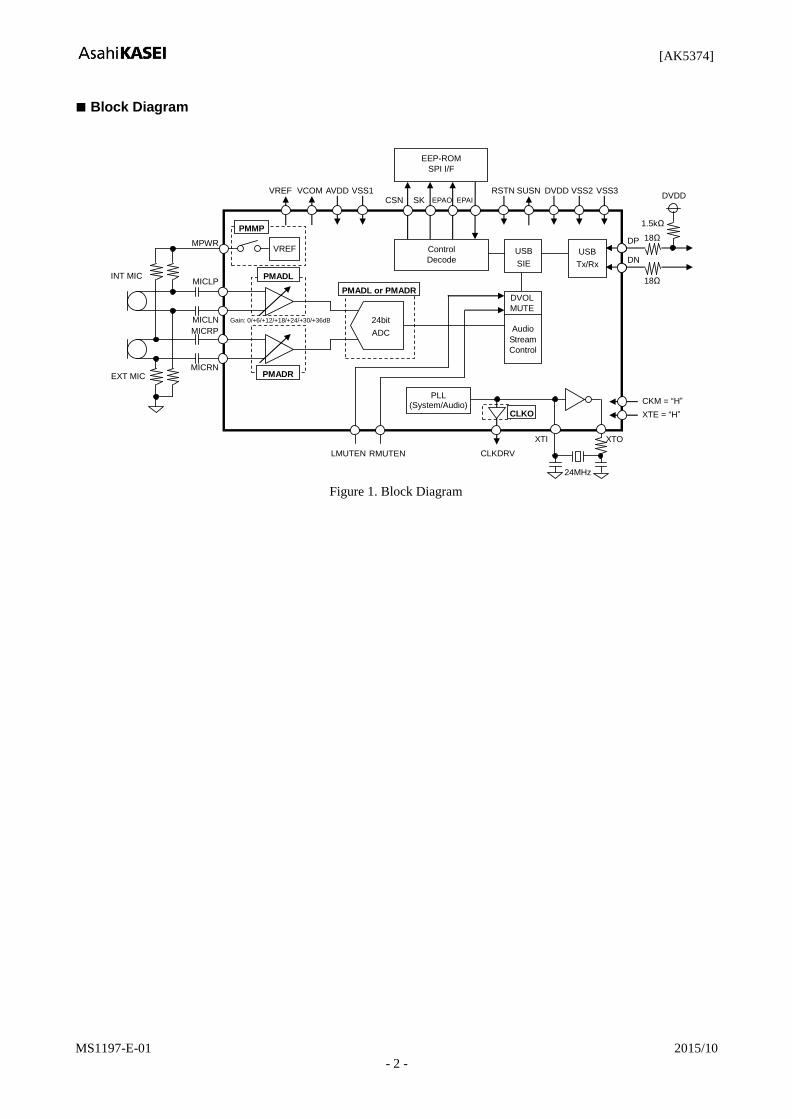
Block Diagram
MPWR
MICLP
MICRP
VREF
XTO XTI
USB
SIE
USB
Tx/Rx
CKM = “H”
Audio
Stream
Control
Control
Decode
RSTN SUSN
CLKDRV
VREF VCOM
MICLN
MICRN
Gain: 0/+6/+12/+18/+24/+30/+36dB
AVDD DVDD VSS2 VSS1 VSS3
PMADL
PMADR
CLKO
PMMP
EEP-ROM
SPI I/F
INT MIC
EXT MIC
PLL (System/Audio)
DVOL
MUTE
LMUTEN RMUTEN
24bit
ADC
ADC
PMADL or PMADR
CSN SK EPAO EPAI
XTE = “H”
DP
DN
DVDD
18Ω
18Ω
1.5kΩ
24MHz
Figure 1. Block Diagram
[AK5374]
MS1197-E-01 2015/10
- 3 -
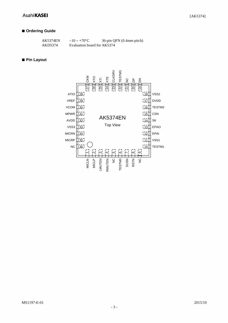
Ordering Guide
AK5374EN 10 +70C 36-pin QFN (0.4mm pitch)
AKD5374 Evaluation board for AK5374
Pin Layout
ATIO
VREF
VCOM
MPWR
AVDD
VSS3
MICRN
MICRP
NC
CK
M
XT
O
XT
I
XT
E
CLK
DR
V
DN
MIC
LN
MIC
LP
LM
UT
EN
RM
UT
EN
NC
TE
ST
M0
S
US
N
RS
TN
VSS2
DVDD
TESTM2
CSN
SK
EPAO
EPAI
VSS1
AK5374EN
Top View
28
29
30
31
32
33
34
35
27
26
25
17
16
15
14
13
12
11
10
24
23
22
21
20
1
2
3
4
5
6
7
8
36
19
18
NC
9
TE
ST
M3
DP
NC
TESTM1
[AK5374]
MS1197-E-01 2015/10
- 4 -
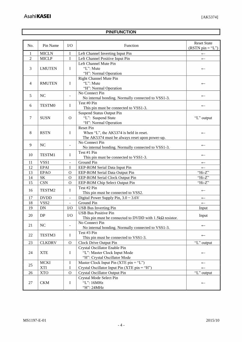
PIN/FUNCTION
No. Pin Name I/O Function Reset State
(RSTN pin = “L”)
1 MICLN I Left Channel Inverting Input Pin ←
2 MICLP I Left Channel Positive Input Pin ←
3 LMUTEN I
Left Channel Mute Pin
“L”: Mute
“H”: Normal Operation
←
4 RMUTEN I
Right Channel Mute Pin
“L”: Mute
“H”: Normal Operation
←
5 NC - No Connect Pin
No internal bonding. Normally connected to VSS1-3. ←
6 TESTM0 I Test #0 Pin
This pin must be connected to VSS1-3. ←
7 SUSN O
Suspend Status Output Pin
“L”: Suspend State
“H”: Normal Operation
“L” output
8 RSTN I
Reset Pin
When “L”, the AK5374 is held in reset.
The AK5374 must be always reset upon power-up.
←
9 NC - No Connect Pin
No internal bonding. Normally connected to VSS1-3. ←
10 TESTM1 I Test #1 Pin
This pin must be connected to VSS1-3. ←
11 VSS1 - Ground Pin ←
12 EPAI I EEP-ROM Serial Data Input Pin ←
13 EPAO O EEP-ROM Serial Data Output Pin “Hi-Z”
14 SK O EEP-ROM Serial Clock Output Pin “Hi-Z”
15 CSN O EEP-ROM Chip Select Output Pin “Hi-Z”
16 TESTM2 I Test #2 Pin
This pin must be connected to VSS2. ←
17 DVDD - Digital Power Supply Pin, 3.0 ~ 3.6V ←
18 VSS2 - Ground Pin ←
19 DN I/O USB Bus Inverting Pin Input
20 DP I/O USB Bus Positive Pin
This pin must be connected to DVDD with 1.5kΩ resistor. Input
21 NC - No Connect Pin
No internal bonding. Normally connected to VSS1-3. ←
22 TESTM3 I Test #3 Pin
This pin must be connected to VSS1-3. ←
23 CLKDRV O Clock Drive Output Pin “L” output
24 XTE I
Crystal Oscillator Enable Pin
“L”: Master Clock Input Mode
“H”: Crystal Oscillator Mode
←
25 MCKI I Master Clock Input Pin (XTE pin = “L”) ←
XTI I Crystal Oscillator Input Pin (XTE pin = “H”) ←
26 XTO O Crystal Oscillator Output Pin “L” output
27 CKM I
Crystal Mode Select Pin
“L”: 16MHz
“H”: 24MHz
←

[AK5374]
MS1197-E-01 2015/10
- 5 -
No. Pin Name I/O Function Reset State
(RSTN pin = “L”)
28 ATIO I/O Test Pin
This pin must be connected to VSS1-3. “Input”
29 VREF O High Level Voltage Reference Output Pin “L” output
30 VCOM O Analog Common Voltage Output Pin “L” output
31 MPWR O Microphone Power Supply Pin “Hi-Z”
32 AVDD - Analog Power Supply Pin, 3.0 ~ 3.6V ←
33 VSS3 - Ground Pin ←
34 MICRN I Right Channel Inverting Input Pin ←
35 MICRP I Right Channel Positive Input Pin ←
36 NC - No Connect Pin
No internal bonding. Normally connected to VSS1-3. ←
Note 1. All digital input pins (EPAI, CKM, LMUTEN, RMUTEN, XTE and TESTM0/1/2/3 pins) must not be left
floating.
[AK5374]
MS1197-E-01 2015/10
- 6 -
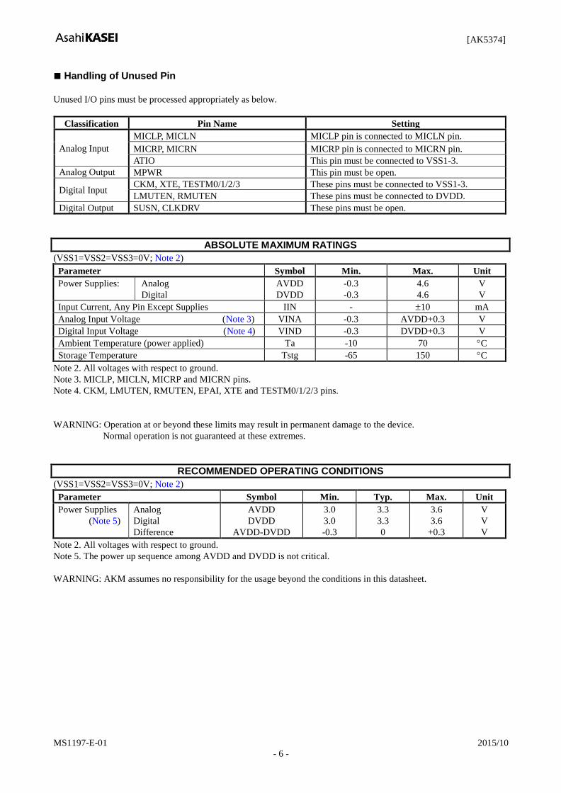
Handling of Unused Pin
Unused I/O pins must be processed appropriately as below.
Classification Pin Name Setting
Analog Input
MICLP, MICLN MICLP pin is connected to MICLN pin.
MICRP, MICRN MICRP pin is connected to MICRN pin.
ATIO This pin must be connected to VSS1-3.
Analog Output MPWR This pin must be open.
Digital Input CKM, XTE, TESTM0/1/2/3 These pins must be connected to VSS1-3.
LMUTEN, RMUTEN These pins must be connected to DVDD.
Digital Output SUSN, CLKDRV These pins must be open.
ABSOLUTE MAXIMUM RATINGS
(VSS1=VSS2=VSS3=0V; Note 2)
Parameter Symbol Min. Max. Unit
Power Supplies:
Analog
Digital
AVDD
DVDD
-0.3
-0.3
4.6
4.6
V
V
Input Current, Any Pin Except Supplies IIN - 10 mA
Analog Input Voltage (Note 3) VINA -0.3 AVDD+0.3 V
Digital Input Voltage (Note 4) VIND -0.3 DVDD+0.3 V
Ambient Temperature (power applied) Ta -10 70 C
Storage Temperature Tstg -65 150 C
Note 2. All voltages with respect to ground.
Note 3. MICLP, MICLN, MICRP and MICRN pins.
Note 4. CKM, LMUTEN, RMUTEN, EPAI, XTE and TESTM0/1/2/3 pins.
WARNING: Operation at or beyond these limits may result in permanent damage to the device.
Normal operation is not guaranteed at these extremes.
RECOMMENDED OPERATING CONDITIONS
(VSS1=VSS2=VSS3=0V; Note 2)
Parameter Symbol Min. Typ. Max. Unit
Power Supplies
(Note 5)
Analog
Digital
Difference
AVDD
DVDD
AVDD-DVDD
3.0
3.0
-0.3
3.3
3.3
0
3.6
3.6
+0.3
V
V
V
Note 2. All voltages with respect to ground.
Note 5. The power up sequence among AVDD and DVDD is not critical.
WARNING: AKM assumes no responsibility for the usage beyond the conditions in this datasheet.
[AK5374]
MS1197-E-01 2015/10
- 7 -
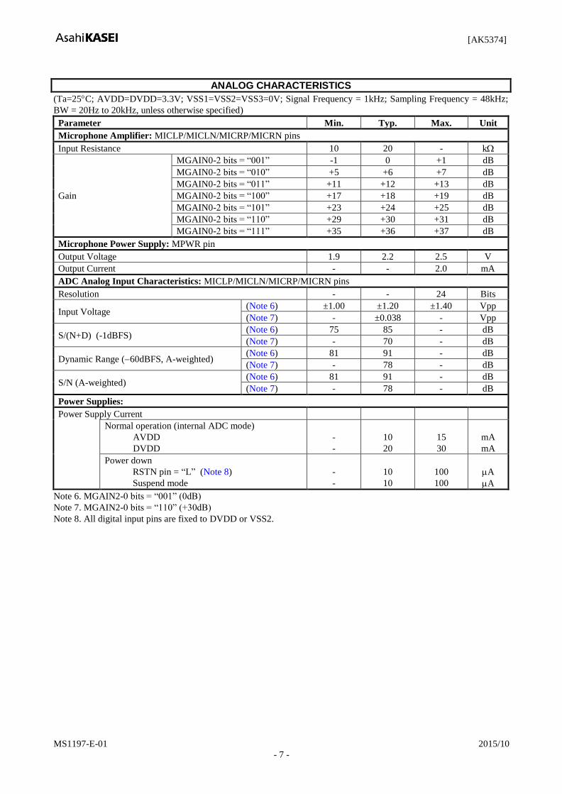
ANALOG CHARACTERISTICS
(Ta=25C; AVDD=DVDD=3.3V; VSS1=VSS2=VSS3=0V; Signal Frequency = 1kHz; Sampling Frequency = 48kHz;
BW = 20Hz to 20kHz, unless otherwise specified)
Parameter Min. Typ. Max. Unit
Microphone Amplifier: MICLP/MICLN/MICRP/MICRN pins
Input Resistance 10 20 - k
Gain
MGAIN0-2 bits = “001” -1 0 +1 dB
MGAIN0-2 bits = “010” +5 +6 +7 dB
MGAIN0-2 bits = “011” +11 +12 +13 dB
MGAIN0-2 bits = “100” +17 +18 +19 dB
MGAIN0-2 bits = “101” +23 +24 +25 dB
MGAIN0-2 bits = “110” +29 +30 +31 dB
MGAIN0-2 bits = “111” +35 +36 +37 dB
Microphone Power Supply: MPWR pin
Output Voltage 1.9 2.2 2.5 V
Output Current - - 2.0 mA
ADC Analog Input Characteristics: MICLP/MICLN/MICRP/MICRN pins
Resolution - - 24 Bits
Input Voltage (Note 6) ±1.00 ±1.20 ±1.40 Vpp
(Note 7) - ±0.038 - Vpp
S/(N+D) (-1dBFS) (Note 6) 75 85 - dB
(Note 7) - 70 - dB
Dynamic Range (60dBFS, A-weighted) (Note 6) 81 91 - dB
(Note 7) - 78 - dB
S/N (A-weighted) (Note 6) 81 91 - dB
(Note 7) - 78 - dB
Power Supplies:
Power Supply Current
Normal operation (internal ADC mode)
AVDD
DVDD
-
-
10
20
15
30
mA
mA
Power down
RSTN pin = “L” (Note 8)
Suspend mode
-
-
10
10
100
100
A
A
Note 6. MGAIN2-0 bits = “001” (0dB)
Note 7. MGAIN2-0 bits = “110” (+30dB)
Note 8. All digital input pins are fixed to DVDD or VSS2.
[AK5374]
MS1197-E-01 2015/10
- 8 -
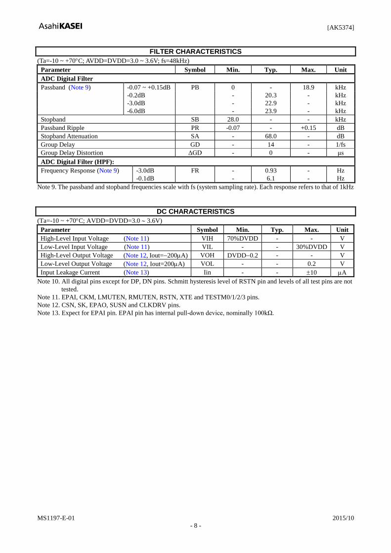
FILTER CHARACTERISTICS
(Ta=-10 ~ +70C; AVDD=DVDD=3.0 ~ 3.6V; fs=48kHz)
Parameter Symbol Min. Typ. Max. Unit
ADC Digital Filter
Passband (Note 9) -0.07 ~ +0.15dB PB 0 - 18.9 kHz
-0.2dB - 20.3 - kHz
-3.0dB - 22.9 - kHz
-6.0dB - 23.9 - kHz
Stopband SB 28.0 - - kHz
Passband Ripple PR -0.07 - +0.15 dB
Stopband Attenuation SA - 68.0 - dB
Group Delay GD - 14 - 1/fs
Group Delay Distortion ΔGD - 0 - μs
ADC Digital Filter (HPF):
Frequency Response (Note 9) -3.0dB
-0.1dB
FR -
-
0.93
6.1
-
-
Hz
Hz
Note 9. The passband and stopband frequencies scale with fs (system sampling rate). Each response refers to that of 1kHz
DC CHARACTERISTICS
(Ta=-10 ~ +70C; AVDD=DVDD=3.0 3.6V)
Parameter Symbol Min. Typ. Max. Unit
High-Level Input Voltage (Note 11) VIH 70%DVDD - - V
Low-Level Input Voltage (Note 11) VIL - - 30%DVDD V
High-Level Output Voltage (Note 12, Iout=200A) VOH DVDD0.2 - - V
Low-Level Output Voltage (Note 12, Iout=200A) VOL - - 0.2 V
Input Leakage Current (Note 13) Iin - - 10 A
Note 10. All digital pins except for DP, DN pins. Schmitt hysteresis level of RSTN pin and levels of all test pins are not
tested.
Note 11. EPAI, CKM, LMUTEN, RMUTEN, RSTN, XTE and TESTM0/1/2/3 pins.
Note 12. CSN, SK, EPAO, SUSN and CLKDRV pins.
Note 13. Expect for EPAI pin. EPAI pin has internal pull-down device, nominally 100kΩ.
[AK5374]
MS1197-E-01 2015/10
- 9 -
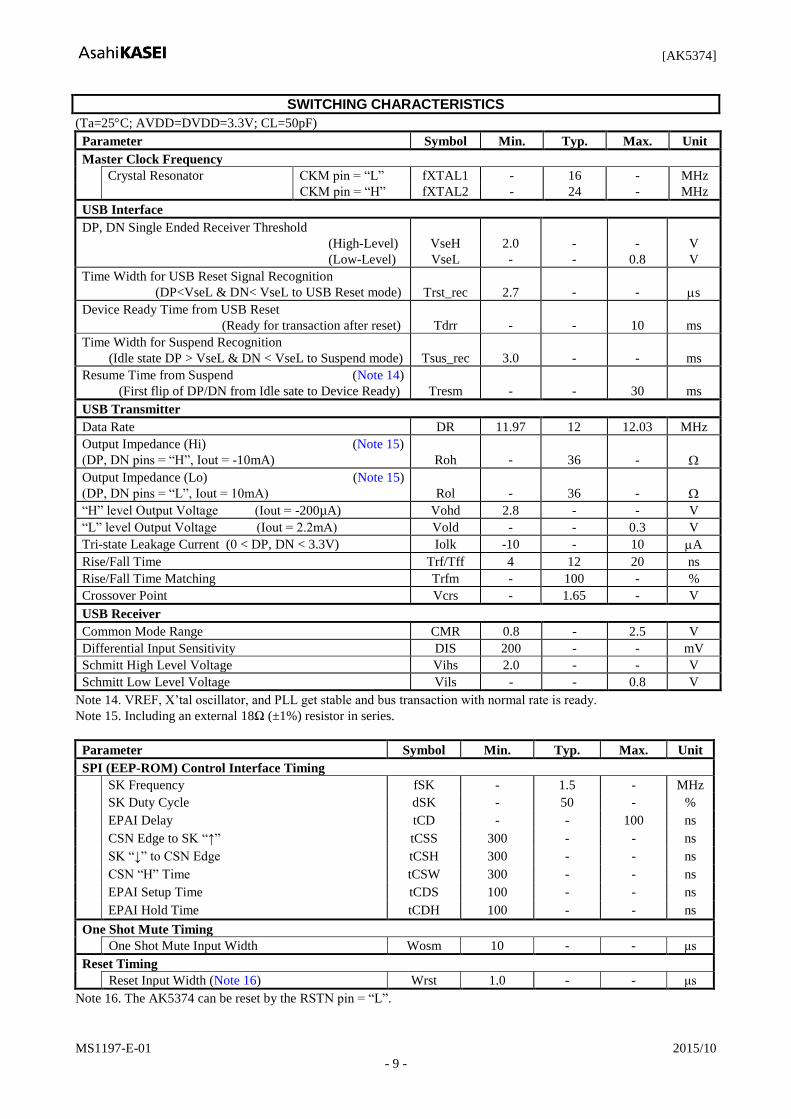
SWITCHING CHARACTERISTICS
(Ta=25C; AVDD=DVDD=3.3V; CL=50pF)
Parameter Symbol Min. Typ. Max. Unit
Master Clock Frequency
Crystal Resonator CKM pin = “L” fXTAL1 - 16 - MHz
CKM pin = “H” fXTAL2 - 24 - MHz
USB Interface
DP, DN Single Ended Receiver Threshold
(High-Level)
(Low-Level)
VseH
VseL
2.0
-
-
-
-
0.8
V
V
Time Width for USB Reset Signal Recognition
(DP<VseL & DN< VseL to USB Reset mode)
Trst_rec
2.7
-
-
s
Device Ready Time from USB Reset
(Ready for transaction after reset)
Tdrr
-
-
10
ms
Time Width for Suspend Recognition
(Idle state DP > VseL & DN < VseL to Suspend mode)
Tsus_rec
3.0
-
-
ms
Resume Time from Suspend (Note 14)
(First flip of DP/DN from Idle sate to Device Ready)
Tresm
-
-
30
ms
USB Transmitter
Data Rate DR 11.97 12 12.03 MHz
Output Impedance (Hi) (Note 15)
(DP, DN pins = “H”, Iout = -10mA)
Roh
-
36
-
Output Impedance (Lo) (Note 15)
(DP, DN pins = “L”, Iout = 10mA)
Rol
-
36
-
“H” level Output Voltage (Iout = -200µA) Vohd 2.8 - - V
“L” level Output Voltage (Iout = 2.2mA) Vold - - 0.3 V
Tri-state Leakage Current (0 < DP, DN < 3.3V) Iolk -10 - 10 A
Rise/Fall Time Trf/Tff 4 12 20 ns
Rise/Fall Time Matching Trfm - 100 - %
Crossover Point Vcrs - 1.65 - V
USB Receiver
Common Mode Range CMR 0.8 - 2.5 V
Differential Input Sensitivity DIS 200 - - mV
Schmitt High Level Voltage Vihs 2.0 - - V
Schmitt Low Level Voltage Vils - - 0.8 V
Note 14. VREF, X’tal oscillator, and PLL get stable and bus transaction with normal rate is ready.
Note 15. Including an external 18Ω (±1%) resistor in series.
Parameter Symbol Min. Typ. Max. Unit
SPI (EEP-ROM) Control Interface Timing
SK Frequency fSK - 1.5 - MHz
SK Duty Cycle dSK - 50 - %
EPAI Delay tCD - - 100 ns
CSN Edge to SK “↑” tCSS 300 - - ns
SK “↓” to CSN Edge tCSH 300 - - ns
CSN “H” Time tCSW 300 - - ns
EPAI Setup Time tCDS 100 - - ns
EPAI Hold Time tCDH 100 - - ns
One Shot Mute Timing
One Shot Mute Input Width Wosm 10 - - μs
Reset Timing
Reset Input Width (Note 16) Wrst 1.0 - - μs
Note 16. The AK5374 can be reset by the RSTN pin = “L”.
[AK5374]
MS1197-E-01 2015/10
- 10 -
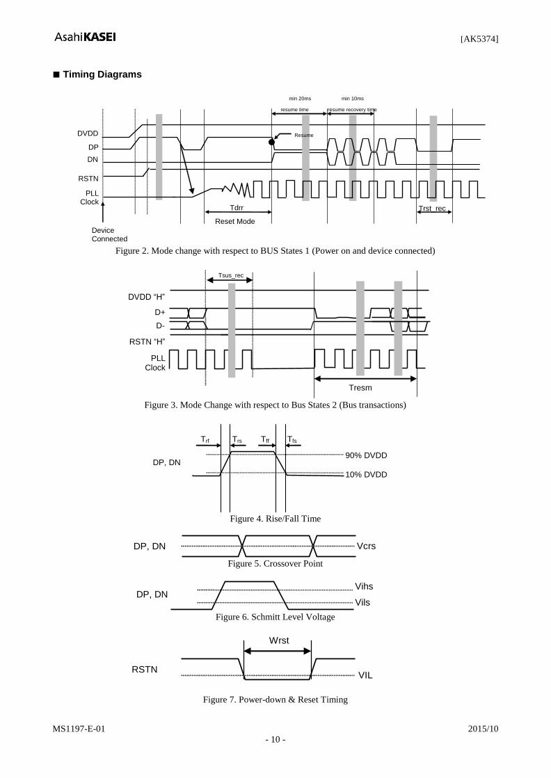
Timing Diagrams
Reset Mode
PLL Clock
DN
DP
DVDD
Device Connected
RSTN
Tdrr
min 20ms
Resume
min 10ms
resume time resume recovery time
Trst_rec
Figure 2. Mode change with respect to BUS States 1 (Power on and device connected)
PLL Clock
D-
D+
DVDD “H”
Tresm
Tsus_rec
RSTN “H”
Figure 3. Mode Change with respect to Bus States 2 (Bus transactions)
10% DVDD
90% DVDD
Trs Trf
DP, DN
Tfs Tff
Figure 4. Rise/Fall Time
Vcrs DP, DN
Figure 5. Crossover Point
Vils
Vihs DP, DN
Figure 6. Schmitt Level Voltage
VIL RSTN
Wrst
Figure 7. Power-down & Reset Timing
[AK5374]
MS1197-E-01 2015/10
- 11 -
VIL
LMUTEN RMUTEN
Wosm
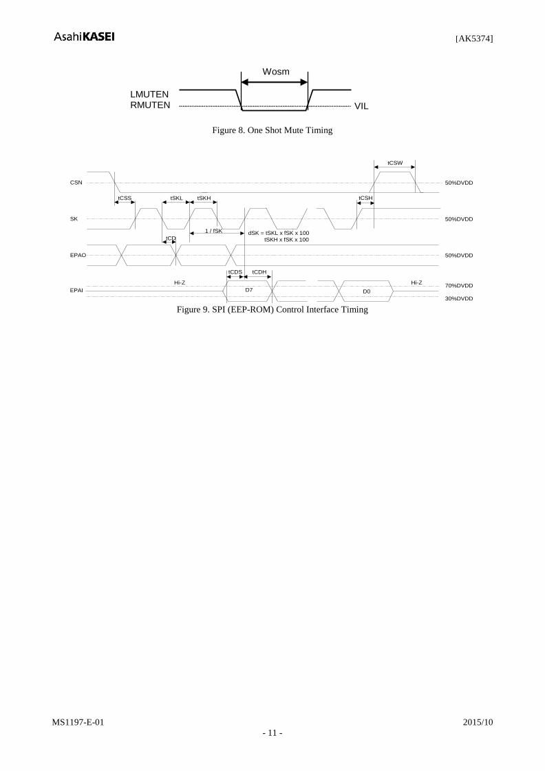
Figure 8. One Shot Mute Timing
CSN
tCSS
SK
tCD
EPAO
tSKHtSKL
1 / fSK
EPAI
Hi-Z
dSK = tSKL x fSK x 100
tSKH x fSK x 100
50%DVDD
tCSH
tCSW
50%DVDD
D7 D0
Hi-Z
50%DVDD
tCDHtCDS
70%DVDD
30%DVDD Figure 9. SPI (EEP-ROM) Control Interface Timing
[AK5374]
MS1197-E-01 2015/10
- 12 -
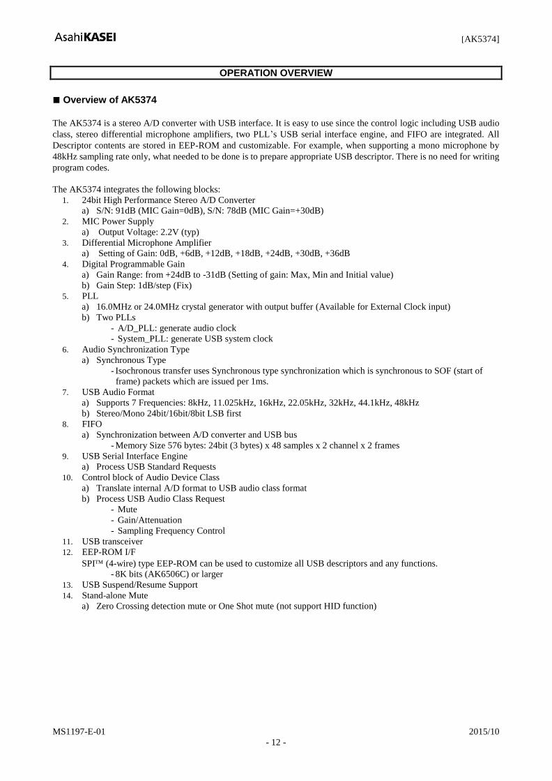
OPERATION OVERVIEW
Overview of AK5374
The AK5374 is a stereo A/D converter with USB interface. It is easy to use since the control logic including USB audio
class, stereo differential microphone amplifiers, two PLL’s USB serial interface engine, and FIFO are integrated. All
Descriptor contents are stored in EEP-ROM and customizable. For example, when supporting a mono microphone by
48kHz sampling rate only, what needed to be done is to prepare appropriate USB descriptor. There is no need for writing
program codes.
The AK5374 integrates the following blocks:
1. 24bit High Performance Stereo A/D Converter
a) S/N: 91dB (MIC Gain=0dB), S/N: 78dB (MIC Gain=+30dB)
2. MIC Power Supply
a) Output Voltage: 2.2V (typ)
3. Differential Microphone Amplifier
a) Setting of Gain: 0dB, +6dB, +12dB, +18dB, +24dB, +30dB, +36dB
4. Digital Programmable Gain
a) Gain Range: from +24dB to -31dB (Setting of gain: Max, Min and Initial value)
b) Gain Step: 1dB/step (Fix)
5. PLL
a) 16.0MHz or 24.0MHz crystal generator with output buffer (Available for External Clock input)
b) Two PLLs
- A/D_PLL: generate audio clock
- System_PLL: generate USB system clock
6. Audio Synchronization Type
a) Synchronous Type
- Isochronous transfer uses Synchronous type synchronization which is synchronous to SOF (start of
frame) packets which are issued per 1ms.
7. USB Audio Format
a) Supports 7 Frequencies: 8kHz, 11.025kHz, 16kHz, 22.05kHz, 32kHz, 44.1kHz, 48kHz
b) Stereo/Mono 24bit/16bit/8bit LSB first
8. FIFO
a) Synchronization between A/D converter and USB bus
- Memory Size 576 bytes: 24bit (3 bytes) x 48 samples x 2 channel x 2 frames
9. USB Serial Interface Engine
a) Process USB Standard Requests
10. Control block of Audio Device Class
a) Translate internal A/D format to USB audio class format
b) Process USB Audio Class Request
- Mute
- Gain/Attenuation
- Sampling Frequency Control
11. USB transceiver
12. EEP-ROM I/F
SPI (4-wire) type EEP-ROM can be used to customize all USB descriptors and any functions.
- 8K bits (AK6506C) or larger
13. USB Suspend/Resume Support
14. Stand-alone Mute
a) Zero Crossing detection mute or One Shot mute (not support HID function)
[AK5374]
MS1197-E-01 2015/10
- 13 -
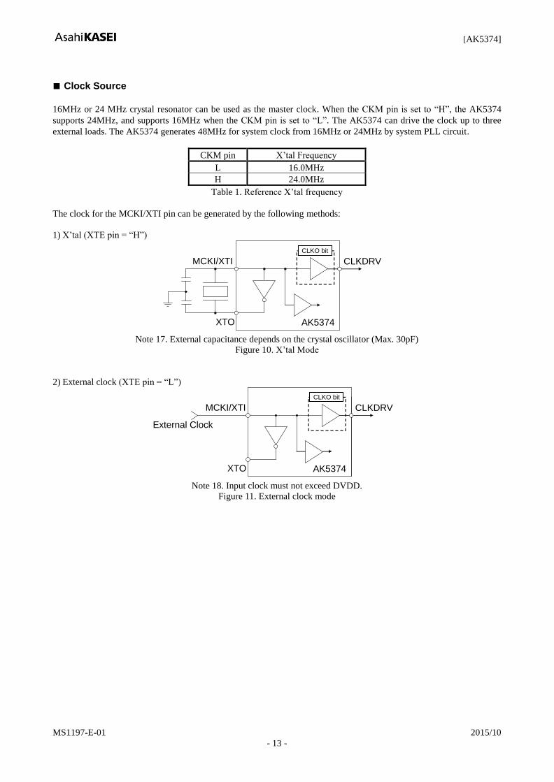
Clock Source
16MHz or 24 MHz crystal resonator can be used as the master clock. When the CKM pin is set to “H”, the AK5374
supports 24MHz, and supports 16MHz when the CKM pin is set to “L”. The AK5374 can drive the clock up to three
external loads. The AK5374 generates 48MHz for system clock from 16MHz or 24MHz by system PLL circuit.
CKM pin X’tal Frequency
L 16.0MHz
H 24.0MHz
Table 1. Reference X’tal frequency
The clock for the MCKI/XTI pin can be generated by the following methods:
1) X’tal (XTE pin = “H”)
MCKI/XTI
XTO AK5374
CLKDRV
CLKO bit
Note 17. External capacitance depends on the crystal oscillator (Max. 30pF)
Figure 10. X’tal Mode
2) External clock (XTE pin = “L”)
MCKI/XTI
XTO
External Clock
AK5374
CLKDRV
CLKO bit
Note 18. Input clock must not exceed DVDD.
Figure 11. External clock mode
[AK5374]
MS1197-E-01 2015/10
- 14 -
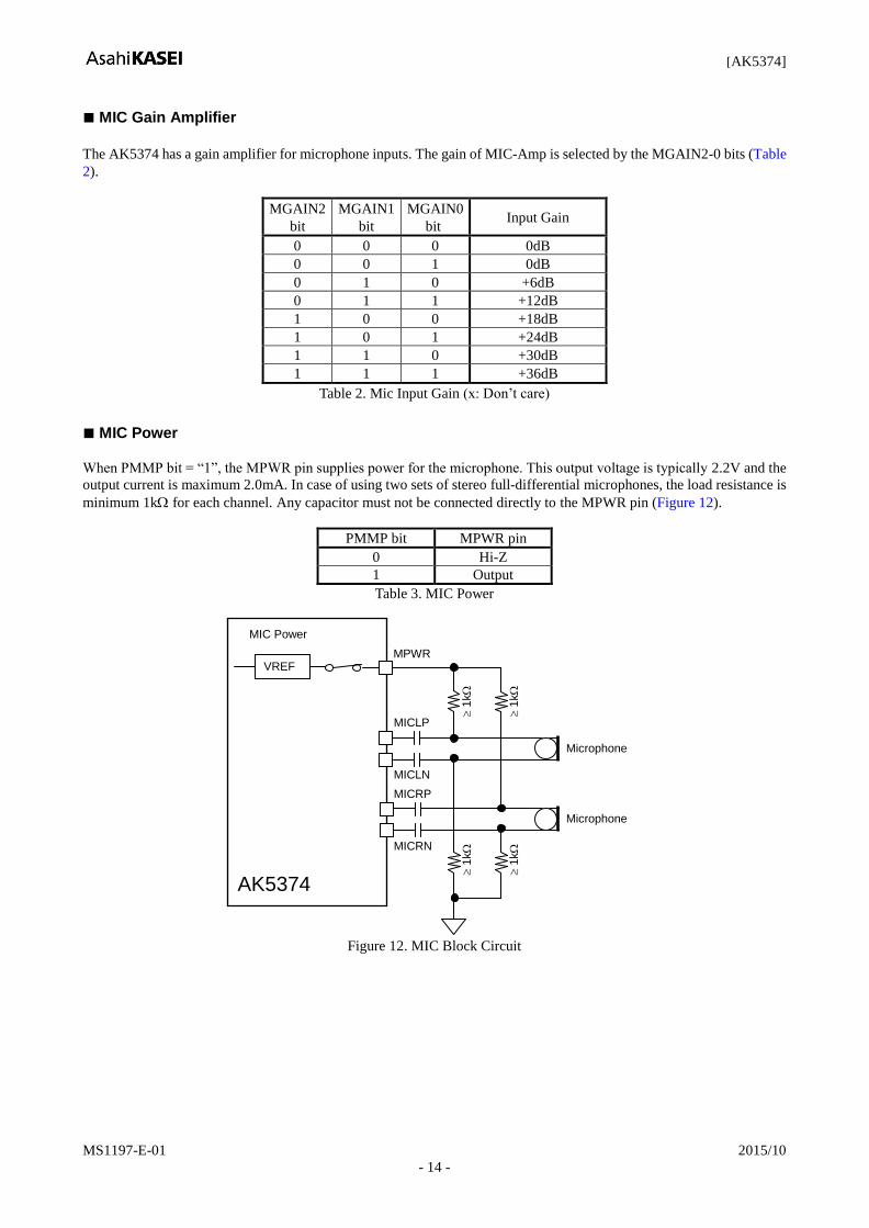
MIC Gain Amplifier
The AK5374 has a gain amplifier for microphone inputs. The gain of MIC-Amp is selected by the MGAIN2-0 bits (Table
2).
MGAIN2
bit
MGAIN1
bit
MGAIN0
bit Input Gain
0 0 0 0dB
0 0 1 0dB
0 1 0 +6dB
0 1 1 +12dB
1 0 0 +18dB
1 0 1 +24dB
1 1 0 +30dB
1 1 1 +36dB
Table 2. Mic Input Gain (x: Don’t care)
MIC Power
When PMMP bit = “1”, the MPWR pin supplies power for the microphone. This output voltage is typically 2.2V and the
output current is maximum 2.0mA. In case of using two sets of stereo full-differential microphones, the load resistance is
minimum 1k for each channel. Any capacitor must not be connected directly to the MPWR pin (Figure 12).
PMMP bit MPWR pin
0 Hi-Z
1 Output
Table 3. MIC Power
MPWR
1
k
MIC Power
Microphone
MICLP
MICLN
Microphone
1
k
VREF
1
k
MICRP
MICRN
1
k
AK5374
Figure 12. MIC Block Circuit
[AK5374]
MS1197-E-01 2015/10
- 15 -
Digital High Pass Filter
The ADC has a digital high pass filter for DC offset cancellation. The cut-off frequency of the HPF is 0.93Hz at
fs=48kHz. The digital high pass filter cut-off frequency scales with the sampling rate (fs). The HPF is always enabled.
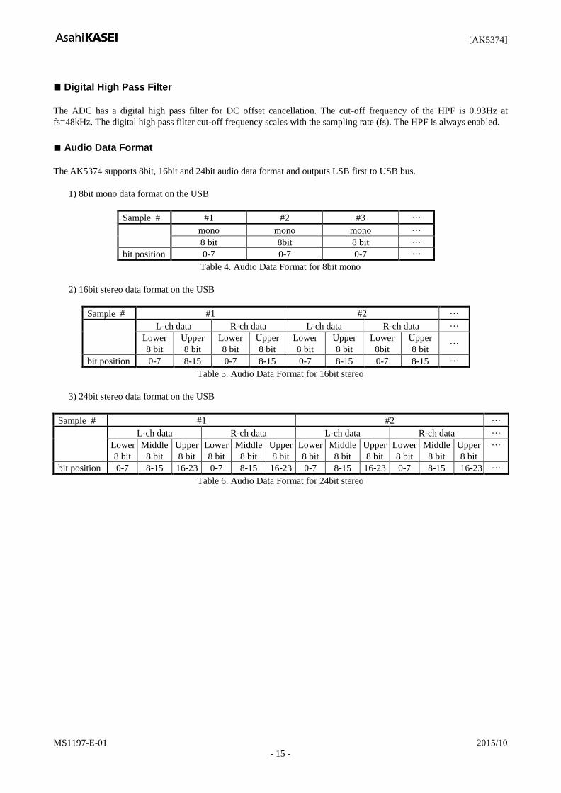
Audio Data Format
The AK5374 supports 8bit, 16bit and 24bit audio data format and outputs LSB first to USB bus.
1) 8bit mono data format on the USB
Sample # #1 #2 #3 ···
mono mono mono ···
8 bit 8bit 8 bit ···
bit position 0-7 0-7 0-7 ···
Table 4. Audio Data Format for 8bit mono
2) 16bit stereo data format on the USB
Sample # #1 #2 ···
L-ch data R-ch data L-ch data R-ch data ···
Lower
8 bit
Upper
8 bit
Lower
8 bit
Upper
8 bit
Lower
8 bit
Upper
8 bit
Lower
8bit
Upper
8 bit ···
bit position 0-7 8-15 0-7 8-15 0-7 8-15 0-7 8-15 ···
Table 5. Audio Data Format for 16bit stereo
3) 24bit stereo data format on the USB
Sample # #1 #2 ···
L-ch data R-ch data L-ch data R-ch data ···
Lower
8 bit
Middle
8 bit
Upper
8 bit
Lower
8 bit
Middle
8 bit
Upper
8 bit
Lower
8 bit
Middle
8 bit
Upper
8 bit
Lower
8 bit
Middle
8 bit
Upper
8 bit
···
bit position 0-7 8-15 16-23 0-7 8-15 16-23 0-7 8-15 16-23 0-7 8-15 16-23 ···
Table 6. Audio Data Format for 24bit stereo
[AK5374]
MS1197-E-01 2015/10
- 16 -
Volume & Mute Control
The AK5374 has a digital volume control which ranges from +24dB to -31dB in 1dB step. The maximum volume, the
minimum and default volumes are defined by EEP-ROM header setting.
When ZCE bit = “1” (Zero cross detection enable), L-channel and R-channel volumes are changed independently on zero
cross or zero cross timeout. Zero cross timeout is set by ZTM1-0 bits (Table 7). When ZCE bit = “0” (zero cross detection
disable), the volume is changed immediately. Mute operation and zero cross detection have the same relation as the
volume mentioned in this section.
ZTM1
bit
ZTM0
bit
Zero Crossing Timeout Period
8kHz 16kHz 44.1kHz
0 0 128/fs 16ms 8ms 2.9ms
0 1 256/fs 32ms 16ms 5.8ms
1 0 512/fs 64ms 32ms 11.6ms
1 1 1024/fs 128ms 64ms 23.2ms
Table 7. Zero Crossing Timeout Period
The AK3573 has the LMUTEN and RMUTEN pins. and they can control mute operations from the device side. However,
because the AK5374 does not have HID function, the mute operation by these pins cannot be acknowledged by the host.
There are two modes for the mute operation by LMUTEN and RMUTEN pins; one is normal mute and the other is
one-shot mute.
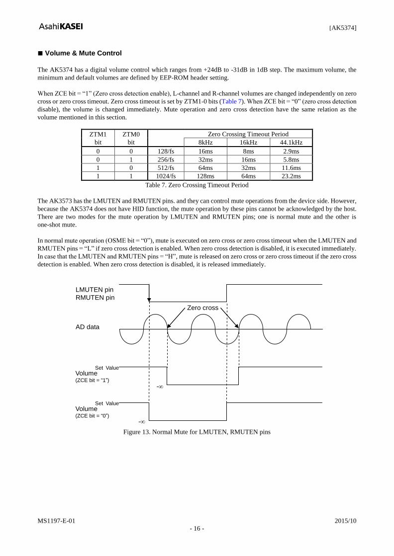
In normal mute operation (OSME bit = “0”), mute is executed on zero cross or zero cross timeout when the LMUTEN and
RMUTEN pins = “L” if zero cross detection is enabled. When zero cross detection is disabled, it is executed immediately.
In case that the LMUTEN and RMUTEN pins = “H”, mute is released on zero cross or zero cross timeout if the zero cross
detection is enabled. When zero cross detection is disabled, it is released immediately.
LMUTEN pin
RMUTEN pin
AD data
Volume (ZCE bit = “1”)
-
Set Value
Zero cross
Volume (ZCE bit = “0”)
-
Set Value
Figure 13. Normal Mute for LMUTEN, RMUTEN pins
[AK5374]
MS1197-E-01 2015/10
- 17 -
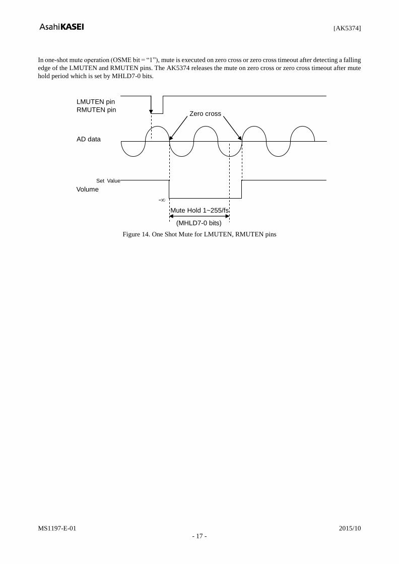
In one-shot mute operation (OSME bit = “1”), mute is executed on zero cross or zero cross timeout after detecting a falling
edge of the LMUTEN and RMUTEN pins. The AK5374 releases the mute on zero cross or zero cross timeout after mute
hold period which is set by MHLD7-0 bits.
LMUTEN pin
RMUTEN pin
AD data
Mute Hold 1~255/fs
(MHLD7-0 bits)
Volume
-
Set Value
Zero cross
Figure 14. One Shot Mute for LMUTEN, RMUTEN pins
[AK5374]
MS1197-E-01 2015/10
- 18 -
Power Management Control
USB specifies that the current at suspend mode must not exceed 500A. When the USB host is in suspend mode, the
SUSN pin also becomes to “L” in order to notify this mode to the external components like DSP’s to observe USB
specification.
Synchronization
The AK5374 supports synchronous type synchronization which is synchronous to SOF (start of frame) packets which are
issued per 1ms.
Descriptor’s Customization
USB audio class has very flexible, but complicated format. In order to keep both of the flexibility and simplicity to use,
the AK5374 utilizes the precompiled control information in EEP-ROM instead of direct USB audio class decoding. Data
in EEP-ROM is divided into two blocks; header information block and USB descriptor block. Header block size is fixed
while USB descriptor block size is variable. Header information includes various control information such as audio
format, the microphone’s gain, power management information, and etc. When the device is powered up, at first the
AK5374 reads the header block in EEP-ROM, and maps these values into the internal registers. Note that 8k bits or larger
SPI type EEP-ROM is available.
The AK5374 does not store all of the descriptors into internal memory at the boot time. Instead, the AK5374 reads the
descriptor from EEP-ROM and transmit it when it receives the “Get Descriptor” Request command. The AK5374
transmits NAK until it is ready to send data.
Header Information includes
1) Power Management Information
2) Microphone Gain
3) Mute Control Information
4) Descriptor related information
a) PCM format(stereo/mono, resolution) and the related alternate setting number
b) Endpoint number
c) Initial/Minimum/Maximum Volume

[AK5374]
MS1197-E-01 2015/10
- 19 -
EEP-ROM Control Interface
Register information and descriptor information on EEP-ROM are read by SPI I/F (CSN, SK, EPAO and EPAI) pins. The
data on the I/F consists of Instruction Byte, Address Byte (MSB first, 16bits) and Input Data Byte (MSB first, 8bits). The
AK5374 outputs Instruction Byte and Address Byte on a falling edge of SK and down-loads address data from EPAI. The
next address data is read by sending SK signal continuously. Data reading ends by a rising edge of CSN. SK clock speed
is typically 1.5MHz. The AK5374 reads data from EEP-ROM according to a request signal from the USB host after
releasing a reset.
CSN
SK
0 1 2 3 4 5 6 7 8 9 10 11 12 13 14 16
EPAO 0 0 0 0 1 1 0 A9 A8 0 0 0 0 0 0 0
17 18 19 20 21 22 23 24 25 26 27 28 29 30 31 32 33 34 35
A6 A4 A2 A0
D7 D5 D3 D1 D7 D5 D3 D1 D8
A7 A5 A3 A1
Instruction Address (n)
“H” or “L” D6 D4 D2 D0 D6
Data (n)
D4 D2 D0
Data (n+1)
EPAI D7 D1 D0
36 37 38 39 40 41 42
Figure 15. EEP-ROM I/F Read Sequence
EEP-ROM memory map
<Header Block> 32 Bytes (fixed)
Addr Name D7 D6 D5 D4 D3 D2 D1 D0
000H Power Management 0 0 0 SELF 0 CLKO PMADR PMADL
001H Microphone Gain Control 0 0 0 PMMP 0 MGAIN2 MGAIN1 MGAIN0
002H Reserved 0 0 0 0 0 0 0 0
003H PCM Format Alt 1 INTFQ12 INTFQ11 INTFQ10 MIX1 RES11 RES10 SIGNED1 STEREO1
004H PCM Format Alt 2 INTFQ22 INTFQ21 INTFQ20 MIX2 RES21 RES20 SIGNED2 STEREO2
005H PCM Format Alt 3 INTFQ32 INTFQ31 INTFQ30 MIX3 RES31 RES30 SIGNED3 STEREO3
006H PCM Format Alt 4 INTFQ42 INTFQ41 INTFQ40 MIX4 RES41 RES40 SIGNED4 STEREO4
007H PCM Format Alt 5 INTFQ52 INTFQ51 INTFQ50 MIX5 RES51 RES50 SIGNED5 STEREO5
008H PCM Format Alt 6 INTFQ62 INTFQ61 INTFQ60 MIX6 RES61 RES60 SIGNED6 STEREO6
009H PCM Format Alt 7 INTFQ72 INTFQ71 INTFQ70 MIX7 RES71 RES70 SIGNED7 STEREO7
00AH Sampling Frequency Alt 1 VALID1 FS48K1 FS44K1 FS32K1 FS22K1 FS16K1 FS11K1 FS8K1
00BH Sampling Frequency Alt 2 VALID2 FS48K2 FS44K2 FS32K2 FS22K2 FS16K2 FS11K2 FS8K2
00CH Sampling Frequency Alt 3 VALID3 FS48K3 FS44K3 FS32K3 FS22K3 FS16K3 FS11K3 FS8K3
00DH Sampling Frequency Alt 4 VALID4 FS48K4 FS44K4 FS32K4 FS22K4 FS16K4 FS11K4 FS8K4
00EH Sampling Frequency Alt 5 VALID5 FS48K5 FS44K5 FS32K5 FS22K5 FS16K5 FS11K5 FS8K5
00FH Sampling Frequency Alt 6 VALID6 FS48K6 FS44K6 FS32K6 FS22K6 FS16K6 FS11K6 FS8K6
010H Sampling Frequency Alt 7 VALID7 FS48K7 FS44K7 FS32K7 FS22K7 FS16K7 FS11K7 FS8K7
011H Endpoint Number 0 0 0 0 0 EPNO2 EPNO1 EPNO0
012H Initial Volume INTVOL7 INTVOL6 INTVOL5 INTVOL4 INTVOL3 INTVOL2 INTVOL1 INTVOL0
013H Minimum Volume MINVOL7 MINVOL6 MINVOL5 MINVOL4 MINVOL3 MINVOL2 MINVOL1 MINVOL0
014H Maximum Volume MAXVOL7 MAXVOL6 MAXVOL5 MAXVOL4 MAXVOL3 MAXVOL2 MAXVOL1 MAXVOL0
015H Mute Control 1 0 0 0 0 OSME ZCE ZTM1 ZTM0
016H Mute Control 2 MHT7 MHT6 MHT5 MHT4 MHT3 MHT2 MHT1 MHT0
017H Reserved 0 0 0 0 0 0 0 0
018H Reserved 0 0 0 0 0 0 0 0
019H Reserved 0 0 0 0 0 0 0 0
01AH Reserved 0 0 0 0 0 0 0 0
01BH Reserved 0 0 0 0 0 0 0 0
01CH Reserved 0 0 0 0 0 0 0 0
01DH Reserved 0 0 0 0 0 0 0 0
01EH Reserved 0 0 0 0 0 0 0 0
01FH Reserved 0 0 0 0 0 0 0 0
[AK5374]
MS1197-E-01 2015/10
- 20 -
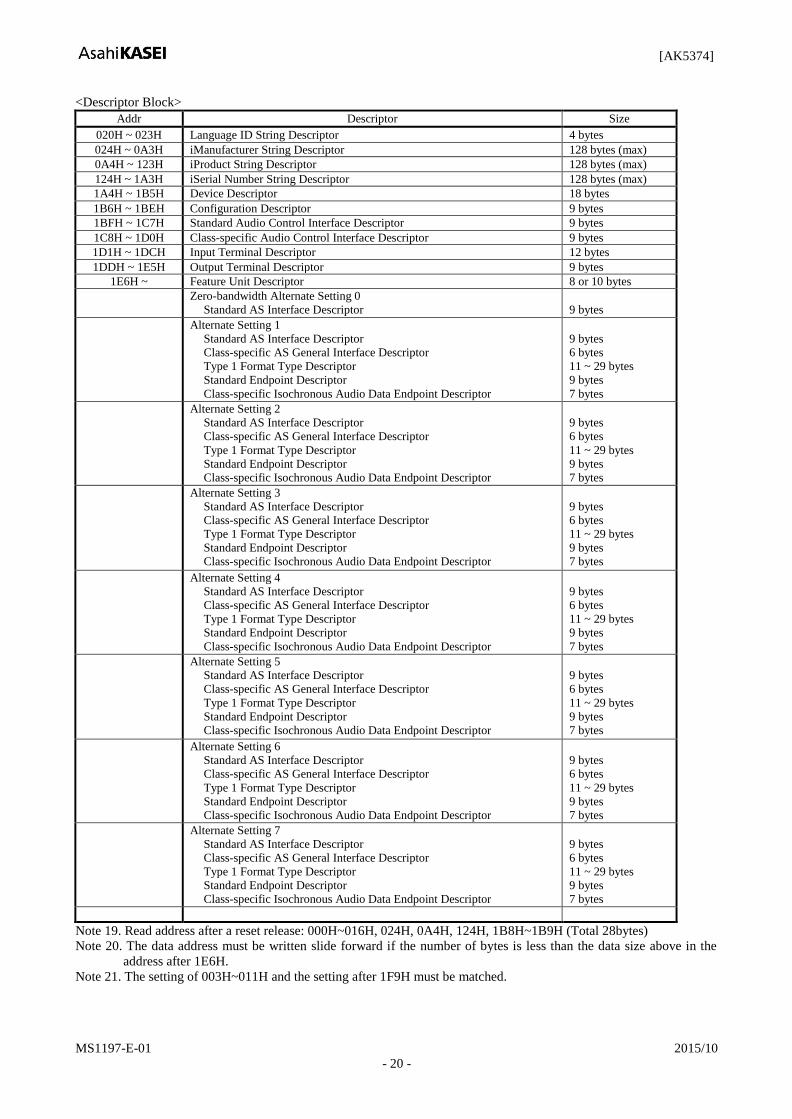
<Descriptor Block>
Addr Descriptor Size
020H ~ 023H Language ID String Descriptor 4 bytes
024H ~ 0A3H iManufacturer String Descriptor 128 bytes (max)
0A4H ~ 123H iProduct String Descriptor 128 bytes (max)
124H ~ 1A3H iSerial Number String Descriptor 128 bytes (max)
1A4H ~ 1B5H Device Descriptor 18 bytes
1B6H ~ 1BEH Configuration Descriptor 9 bytes
1BFH ~ 1C7H Standard Audio Control Interface Descriptor 9 bytes
1C8H ~ 1D0H Class-specific Audio Control Interface Descriptor 9 bytes
1D1H ~ 1DCH Input Terminal Descriptor 12 bytes
1DDH ~ 1E5H Output Terminal Descriptor 9 bytes
1E6H ~ Feature Unit Descriptor 8 or 10 bytes
Zero-bandwidth Alternate Setting 0
Standard AS Interface Descriptor
9 bytes
Alternate Setting 1
Standard AS Interface Descriptor
Class-specific AS General Interface Descriptor
Type 1 Format Type Descriptor
Standard Endpoint Descriptor
Class-specific Isochronous Audio Data Endpoint Descriptor
9 bytes
6 bytes
11 ~ 29 bytes
9 bytes
7 bytes
Alternate Setting 2
Standard AS Interface Descriptor
Class-specific AS General Interface Descriptor
Type 1 Format Type Descriptor
Standard Endpoint Descriptor
Class-specific Isochronous Audio Data Endpoint Descriptor
9 bytes
6 bytes
11 ~ 29 bytes
9 bytes
7 bytes
Alternate Setting 3
Standard AS Interface Descriptor
Class-specific AS General Interface Descriptor
Type 1 Format Type Descriptor
Standard Endpoint Descriptor
Class-specific Isochronous Audio Data Endpoint Descriptor
9 bytes
6 bytes
11 ~ 29 bytes
9 bytes
7 bytes
Alternate Setting 4
Standard AS Interface Descriptor
Class-specific AS General Interface Descriptor
Type 1 Format Type Descriptor
Standard Endpoint Descriptor
Class-specific Isochronous Audio Data Endpoint Descriptor
9 bytes
6 bytes
11 ~ 29 bytes
9 bytes
7 bytes
Alternate Setting 5
Standard AS Interface Descriptor
Class-specific AS General Interface Descriptor
Type 1 Format Type Descriptor
Standard Endpoint Descriptor
Class-specific Isochronous Audio Data Endpoint Descriptor
9 bytes
6 bytes
11 ~ 29 bytes
9 bytes
7 bytes
Alternate Setting 6
Standard AS Interface Descriptor
Class-specific AS General Interface Descriptor
Type 1 Format Type Descriptor
Standard Endpoint Descriptor
Class-specific Isochronous Audio Data Endpoint Descriptor
9 bytes
6 bytes
11 ~ 29 bytes
9 bytes
7 bytes
Alternate Setting 7
Standard AS Interface Descriptor
Class-specific AS General Interface Descriptor
Type 1 Format Type Descriptor
Standard Endpoint Descriptor
Class-specific Isochronous Audio Data Endpoint Descriptor
9 bytes
6 bytes
11 ~ 29 bytes
9 bytes
7 bytes
Note 19. Read address after a reset release: 000H~016H, 024H, 0A4H, 124H, 1B8H~1B9H (Total 28bytes)
Note 20. The data address must be written slide forward if the number of bytes is less than the data size above in the
address after 1E6H.
Note 21. The setting of 003H~011H and the setting after 1F9H must be matched.
[AK5374]
MS1197-E-01 2015/10
- 21 -
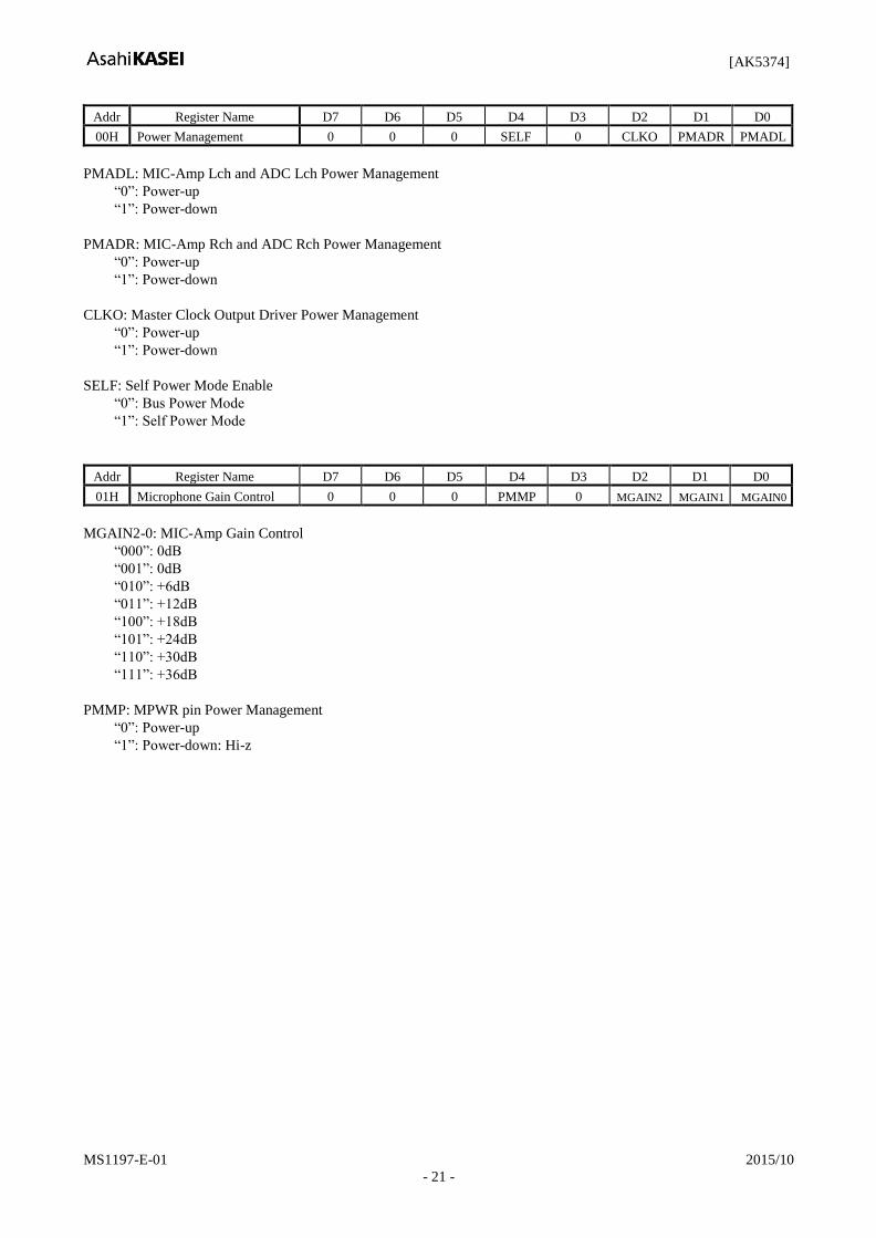
Addr Register Name D7 D6 D5 D4 D3 D2 D1 D0
00H Power Management 0 0 0 SELF 0 CLKO PMADR PMADL
PMADL: MIC-Amp Lch and ADC Lch Power Management
“0”: Power-up
“1”: Power-down
PMADR: MIC-Amp Rch and ADC Rch Power Management
“0”: Power-up
“1”: Power-down
CLKO: Master Clock Output Driver Power Management
“0”: Power-up
“1”: Power-down
SELF: Self Power Mode Enable
“0”: Bus Power Mode
“1”: Self Power Mode
Addr Register Name D7 D6 D5 D4 D3 D2 D1 D0
01H Microphone Gain Control 0 0 0 PMMP 0 MGAIN2 MGAIN1 MGAIN0
MGAIN2-0: MIC-Amp Gain Control
“000”: 0dB
“001”: 0dB
“010”: +6dB
“011”: +12dB
“100”: +18dB
“101”: +24dB
“110”: +30dB
“111”: +36dB
PMMP: MPWR pin Power Management
“0”: Power-up
“1”: Power-down: Hi-z
[AK5374]
MS1197-E-01 2015/10
- 22 -
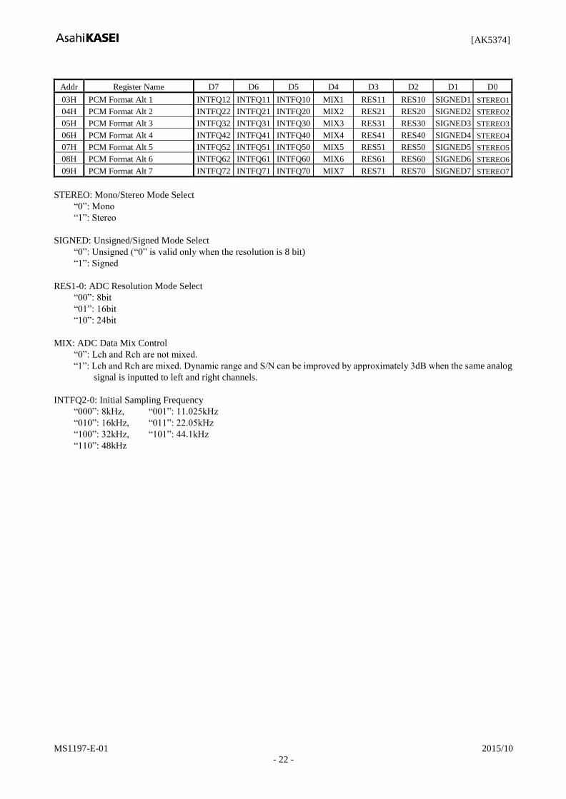
Addr Register Name D7 D6 D5 D4 D3 D2 D1 D0
03H PCM Format Alt 1 INTFQ12 INTFQ11 INTFQ10 MIX1 RES11 RES10 SIGNED1 STEREO1
04H PCM Format Alt 2 INTFQ22 INTFQ21 INTFQ20 MIX2 RES21 RES20 SIGNED2 STEREO2
05H PCM Format Alt 3 INTFQ32 INTFQ31 INTFQ30 MIX3 RES31 RES30 SIGNED3 STEREO3
06H PCM Format Alt 4 INTFQ42 INTFQ41 INTFQ40 MIX4 RES41 RES40 SIGNED4 STEREO4
07H PCM Format Alt 5 INTFQ52 INTFQ51 INTFQ50 MIX5 RES51 RES50 SIGNED5 STEREO5
08H PCM Format Alt 6 INTFQ62 INTFQ61 INTFQ60 MIX6 RES61 RES60 SIGNED6 STEREO6
09H PCM Format Alt 7 INTFQ72 INTFQ71 INTFQ70 MIX7 RES71 RES70 SIGNED7 STEREO7
STEREO: Mono/Stereo Mode Select
“0”: Mono
“1”: Stereo
SIGNED: Unsigned/Signed Mode Select
“0”: Unsigned (“0” is valid only when the resolution is 8 bit)
“1”: Signed
RES1-0: ADC Resolution Mode Select
“00”: 8bit
“01”: 16bit
“10”: 24bit
MIX: ADC Data Mix Control
“0”: Lch and Rch are not mixed.
“1”: Lch and Rch are mixed. Dynamic range and S/N can be improved by approximately 3dB when the same analog
signal is inputted to left and right channels.
INTFQ2-0: Initial Sampling Frequency
“000”: 8kHz, “001”: 11.025kHz
“010”: 16kHz, “011”: 22.05kHz
“100”: 32kHz, “101”: 44.1kHz
“110”: 48kHz
[AK5374]
MS1197-E-01 2015/10
- 23 -
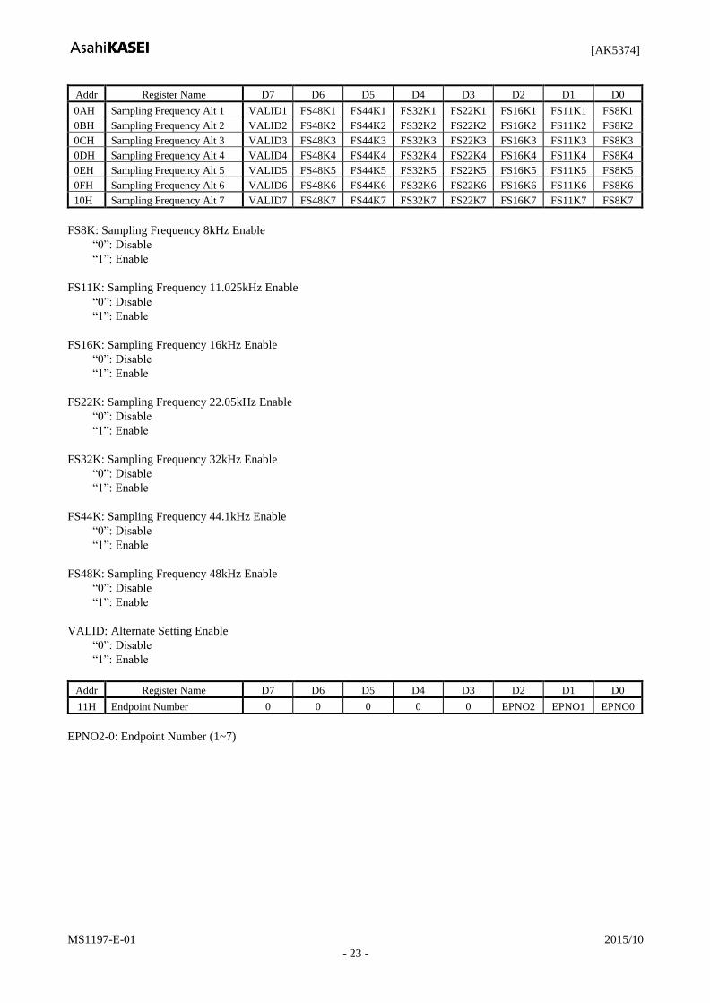
Addr Register Name D7 D6 D5 D4 D3 D2 D1 D0
0AH Sampling Frequency Alt 1 VALID1 FS48K1 FS44K1 FS32K1 FS22K1 FS16K1 FS11K1 FS8K1
0BH Sampling Frequency Alt 2 VALID2 FS48K2 FS44K2 FS32K2 FS22K2 FS16K2 FS11K2 FS8K2
0CH Sampling Frequency Alt 3 VALID3 FS48K3 FS44K3 FS32K3 FS22K3 FS16K3 FS11K3 FS8K3
0DH Sampling Frequency Alt 4 VALID4 FS48K4 FS44K4 FS32K4 FS22K4 FS16K4 FS11K4 FS8K4
0EH Sampling Frequency Alt 5 VALID5 FS48K5 FS44K5 FS32K5 FS22K5 FS16K5 FS11K5 FS8K5
0FH Sampling Frequency Alt 6 VALID6 FS48K6 FS44K6 FS32K6 FS22K6 FS16K6 FS11K6 FS8K6
10H Sampling Frequency Alt 7 VALID7 FS48K7 FS44K7 FS32K7 FS22K7 FS16K7 FS11K7 FS8K7
FS8K: Sampling Frequency 8kHz Enable
“0”: Disable
“1”: Enable
FS11K: Sampling Frequency 11.025kHz Enable
“0”: Disable
“1”: Enable
FS16K: Sampling Frequency 16kHz Enable
“0”: Disable
“1”: Enable
FS22K: Sampling Frequency 22.05kHz Enable
“0”: Disable
“1”: Enable
FS32K: Sampling Frequency 32kHz Enable
“0”: Disable
“1”: Enable
FS44K: Sampling Frequency 44.1kHz Enable
“0”: Disable
“1”: Enable
FS48K: Sampling Frequency 48kHz Enable
“0”: Disable
“1”: Enable
VALID: Alternate Setting Enable
“0”: Disable
“1”: Enable
Addr Register Name D7 D6 D5 D4 D3 D2 D1 D0
11H Endpoint Number 0 0 0 0 0 EPNO2 EPNO1 EPNO0
EPNO2-0: Endpoint Number (1~7)
[AK5374]
MS1197-E-01 2015/10
- 24 -
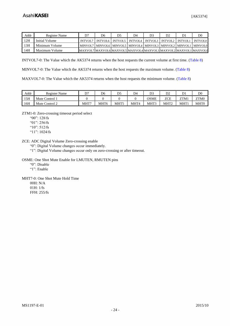
Addr Register Name D7 D6 D5 D4 D3 D2 D1 D0
12H Initial Volume INTVOL7 INTVOL6 INTVOL5 INTVOL4 INTVOL3 INTVOL2 INTVOL1 INTVOL0
13H Minimum Volume MINVOL7 MINVOL6 MINVOL5 MINVOL4 MINVOL3 MINVOL2 MINVOL1 MINVOL0
14H Maximum Volume MAXVOL7 MAXVOL6 MAXVOL5 MAXVOL4 MAXVOL3 MAXVOL2 MAXVOL1 MAXVOL0
INTVOL7-0: The Value which the AK5374 returns when the host requests the current volume at first time. (Table 8)
MINVOL7-0: The Value which the AK5374 returns when the host requests the maximum volume. (Table 8)
MAXVOL7-0: The Value which the AK5374 returns when the host requests the minimum volume. (Table 8)
Addr Register Name D7 D6 D5 D4 D3 D2 D1 D0
15H Mute Control 1 0 0 0 0 OSME ZCE ZTM1 ZTM0
16H Mute Control 2 MHT7 MHT6 MHT5 MHT4 MHT3 MHT2 MHT1 MHT0
ZTM1-0: Zero-crossing timeout period select
“00”: 128/fs
“01”: 256/fs
“10”: 512/fs
“11”: 1024/fs
ZCE: ADC Digital Volume Zero-crossing enable
“0”: Digital Volume changes occur immediately.
“1”: Digital Volume changes occur only on zero-crossing or after timeout.
OSME: One Shot Mute Enable for LMUTEN, RMUTEN pins
“0”: Disable
“1”: Enable
MHT7-0: One Shot Mute Hold Time
00H: N/A
01H: 1/fs
FFH: 255/fs
[AK5374]
MS1197-E-01 2015/10
- 25 -
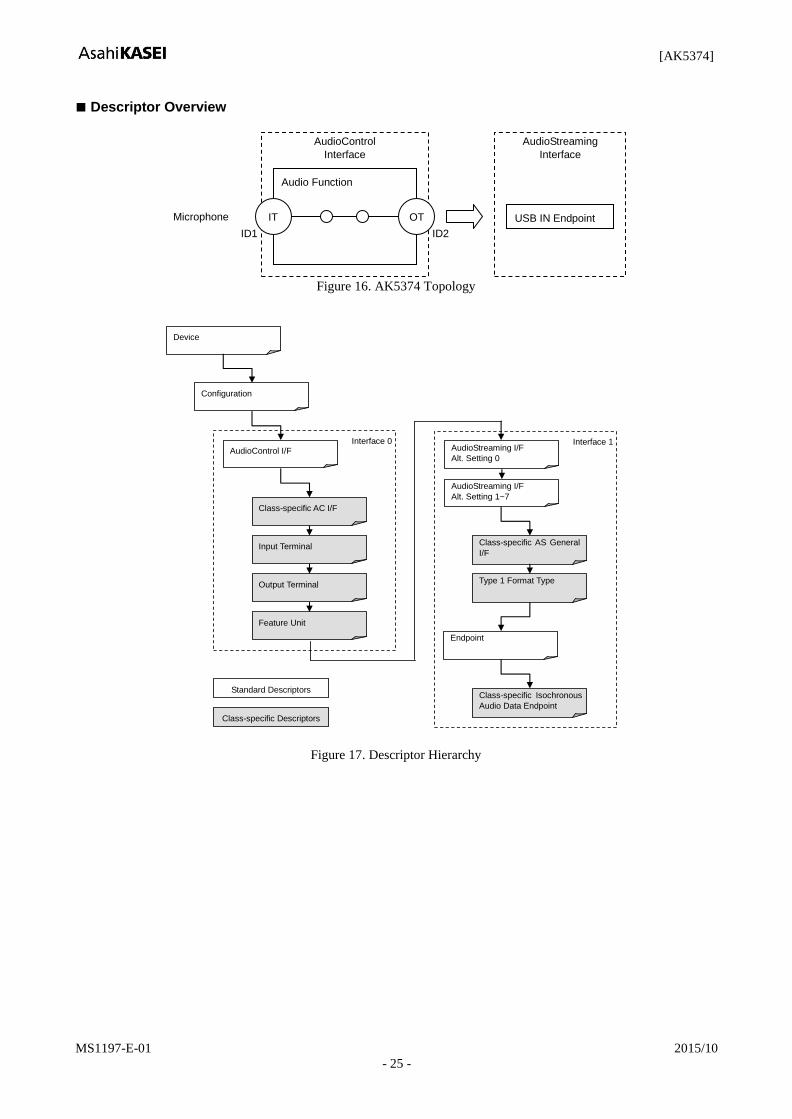
Descriptor Overview
AudioStreaming
Interface
AudioControl
Interface
Audio Function
IT OT USB IN Endpoint Microphone
ID1 ID2
Figure 16. AK5374 Topology
AudioStreaming I/F
Alt. Setting 0
AudioStreaming I/F
Alt. Setting 1~7
Device
Configuration
AudioControl I/F
Class-specific AC I/F
Input Terminal
Output Terminal
Feature Unit
Interface 0 Interface 1
Class-specific AS General
I/F
Type 1 Format Type
Endpoint
Class-specific Isochronous
Audio Data Endpoint
Standard Descriptors
Class-specific Descriptors
Figure 17. Descriptor Hierarchy

[AK5374]
MS1197-E-01 2015/10
- 26 -
Descriptors Specification (for example)
Customizable Block
All Descriptor contents are stored in EEP-ROM and customizable with some restrictions.
a) Device Descriptor, String Descriptor
- Maximum Packet Size
- idVendor
- idProduct
- Manufacturer Name (max. 126bytes)
- Product Name (max. 126bytes)
- Serial Number (max. 126bytes)
- Language ID
b) Configuration Descriptor
- Power Consumption
c) Feature Unit Descriptor: <Active> or < Bypass>
- If Feature Unit is not defined in the descriptor, the volume is fixed to the initial value which is described in
the EEP-ROM header block
d) PCM format (Note that the AK5374 supports 7 sample rates even when only 1 sample rate is specified in the
descriptor.)
e) Endpoint Number
f) Maximum Value of Digital Gain
g) Minimum Value of Digital Gain
h) Initial Value of Digital Gain
Uncustomizable Block
a) Configuration Number (1)
b) Interface Number (1)
c) Input Terminal ID (1)
d) Output Terminal ID (2)
e) Feature Unit ID (3)
f) Synchronization way (support Synchronous Type)
g) Maximum Alternate Setting number (7)
h) Endpoint Number (1-7)
1. Device descriptor
Offset Field Size Value Description
0 bLength 1 0x12 Size of this descriptor in bytes
1 bDescriptorType 1 0x01 DEVICE descriptor
2 bcdUSB 2 0x0200 2.0 – USB Specification Release Number in Binary-Coded
Decimal.
4 bDeviceClass 1 0x00 Device defined at Interface level
5 bDeviceSubClass 1 0x00 Not used. Must be set to 0.
6 bDeviceProtocol 1 0x00 Not used. Must be set to 0.
7 bMaxPacketSize0 1 0x08 8 bytes – Maximum packet size for endpoint zero
8 idVendor 2 0x0556 AKM – Vendor ID (assigned by the USB-IF)
10 idProduct 2 0x0007 AK5374 – Product ID (assigned by the manufacturer)
12 bcdDevice 2 0x0100 1.00 – Device release number in binary-coded decimal
14 iManufacturer 1 0x01 Index of string descriptor describing manufacturer
15 iProduct 1 0x02 Index of string descriptor describing product
16 iSerialNumber 1 0x03 Index of string descriptor describing the device’s serial
number
17 bNumConfigurations 1 0x01 One configuration
[AK5374]
MS1197-E-01 2015/10
- 27 -
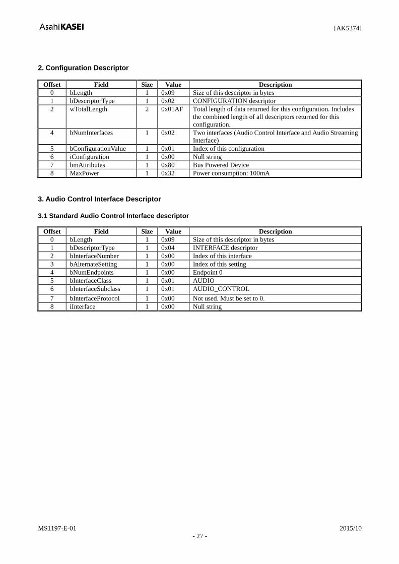
2. Configuration Descriptor
Offset Field Size Value Description
0 bLength 1 0x09 Size of this descriptor in bytes
1 bDescriptorType 1 0x02 CONFIGURATION descriptor
2 wTotalLength 2 0x01AF Total length of data returned for this configuration. Includes
the combined length of all descriptors returned for this
configuration.
4 bNumInterfaces 1 0x02 Two interfaces (Audio Control Interface and Audio Streaming
Interface)
5 bConfigurationValue 1 0x01 Index of this configuration
6 iConfiguration 1 0x00 Null string
7 bmAttributes 1 0x80 Bus Powered Device
8 MaxPower 1 0x32 Power consumption: 100mA
3. Audio Control Interface Descriptor
3.1 Standard Audio Control Interface descriptor
Offset Field Size Value Description
0 bLength 1 0x09 Size of this descriptor in bytes
1 bDescriptorType 1 0x04 INTERFACE descriptor
2 bInterfaceNumber 1 0x00 Index of this interface
3 bAlternateSetting 1 0x00 Index of this setting
4 bNumEndpoints 1 0x00 Endpoint 0
5 bInterfaceClass 1 0x01 AUDIO
6 bInterfaceSubclass 1 0x01 AUDIO_CONTROL
7 bInterfaceProtocol 1 0x00 Not used. Must be set to 0.
8 iInterface 1 0x00 Null string

[AK5374]
MS1197-E-01 2015/10
- 28 -
3.2 Class-specific Audio Control Interface Descriptor
Offset Field Size Value Description
0 bLength 1 0x09 Size of this descriptor in bytes
1 bDescriptorType 1 0x24 CS_INTERFACE
2 bDescriptorSubtype 1 0x01 HEADER subtype
3 bcdADC 2 0x0100 1.0 – Audio Device Class specification release number in
Binary-Coded Decimal.
5 wTotalLength 2 0x0028 Total size of class-specific Audio Control Interface descriptors
(includes this descriptor)
7 bInCollection 1 0x01 Number of streaming interfaces
8 bInterfaceNr(1) 1 0x01 Streaming interface number 1 belongs to this audio control
interface.
3.3 Input Terminal Descriptor
Offset Field Size Value Description
0 bLength 1 0x0C Size of this descriptor in bytes
1 bDescriptorType 1 0x24 CS_INTERFACE
2 bDescriptorSubtype 1 0x02 INPUT_TERMINAL subtype
3 bTerminalID 1 0x01 ID of this terminal
4 wTerminalType 2 0x0201 Terminal is Microphone
6 bAssocTerminal 1 0x02 ID of associated Output Terminal is 0x02
7 bNrChannels 1 0x02 Two channels (Stereo)
8 wChannelConfig 2 0x0003 Left/Right Front
10 iChannelNames 1 0x00 Not used. Must be set to 0.
11 iTerminal 1 0x00 Not used. Must be set to 0.
3.4 Output Terminal Descriptor
Offset Field Size Value Description
0 bLength 1 0x09 Size of this descriptor in bytes
1 bDescriptorType 1 0x24 CS_INTERFACE
2 bDescriptorSubtype 1 0x03 OUTPUT_TERMINAL subtype
3 bTerminalID 1 0x02 ID of this terminal
4 wTerminalType 2 0x0101 USB Streamer
6 bAssocTerminal 1 0x01 ID of associate Input Terminal is 0x01
7 bSourceID 1 0x03 From Feature Unit
8 iTerminal 1 0x00 Not used. Must be set to 0.
3.5 Feature Unit Descriptor
Offset Field Size Value Description
0 bLength 1 0x0A Size of this descriptor in bytes
1 bDescriptorType 1 0x24 CS_INTERFACE
2 bDescriptorSubtype 1 0x06 FEATURE_UNIT descriptor subtype
3 bUnitID 1 0x03 ID of this feature Unit
4 bSourceID 1 0x01 ID to Terminal to which this is connected.
5 bControlSize 1 0x01 Size in bytes of an element of the bmaControl()
6 bmaControls(0) 1 0x01 D0(Mute) is enable for ch 0
7 bmaControls(1) 1 0x02 D1(Volume) is enable for ch 1 (Left)
8 bmaControls(2) 1 0x02 D1(Volume) is enable for ch 2 (Right)
9 iFeature 1 0x00 Not used. Must be set to 0.
[AK5374]
MS1197-E-01 2015/10
- 29 -
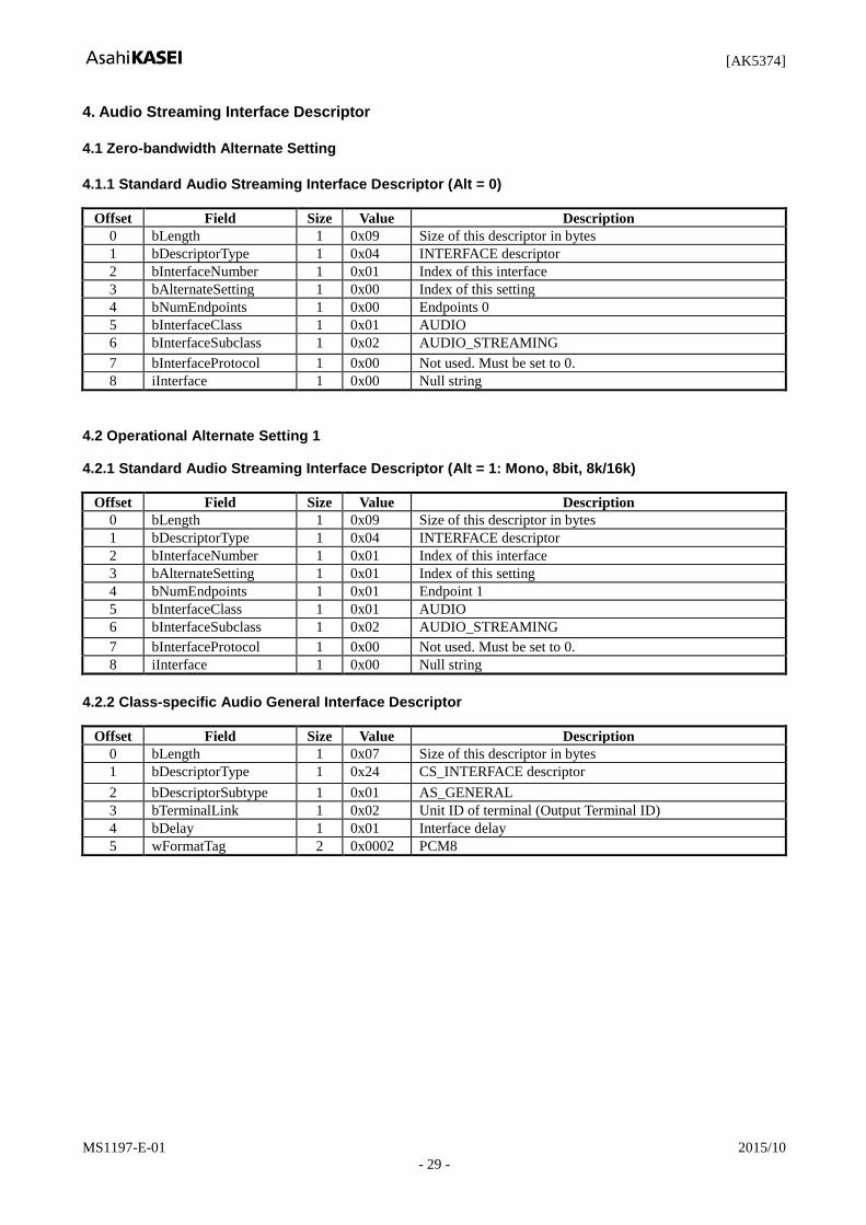
4. Audio Streaming Interface Descriptor
4.1 Zero-bandwidth Alternate Setting
4.1.1 Standard Audio Streaming Interface Descriptor (Alt = 0)
Offset Field Size Value Description
0 bLength 1 0x09 Size of this descriptor in bytes
1 bDescriptorType 1 0x04 INTERFACE descriptor
2 bInterfaceNumber 1 0x01 Index of this interface
3 bAlternateSetting 1 0x00 Index of this setting
4 bNumEndpoints 1 0x00 Endpoints 0
5 bInterfaceClass 1 0x01 AUDIO
6 bInterfaceSubclass 1 0x02 AUDIO_STREAMING
7 bInterfaceProtocol 1 0x00 Not used. Must be set to 0.
8 iInterface 1 0x00 Null string
4.2 Operational Alternate Setting 1
4.2.1 Standard Audio Streaming Interface Descriptor (Alt = 1: Mono, 8bit, 8k/16k)
Offset Field Size Value Description
0 bLength 1 0x09 Size of this descriptor in bytes
1 bDescriptorType 1 0x04 INTERFACE descriptor
2 bInterfaceNumber 1 0x01 Index of this interface
3 bAlternateSetting 1 0x01 Index of this setting
4 bNumEndpoints 1 0x01 Endpoint 1
5 bInterfaceClass 1 0x01 AUDIO
6 bInterfaceSubclass 1 0x02 AUDIO_STREAMING
7 bInterfaceProtocol 1 0x00 Not used. Must be set to 0.
8 iInterface 1 0x00 Null string
4.2.2 Class-specific Audio General Interface Descriptor
Offset Field Size Value Description
0 bLength 1 0x07 Size of this descriptor in bytes
1 bDescriptorType 1 0x24 CS_INTERFACE descriptor
2 bDescriptorSubtype 1 0x01 AS_GENERAL
3 bTerminalLink 1 0x02 Unit ID of terminal (Output Terminal ID)
4 bDelay 1 0x01 Interface delay
5 wFormatTag 2 0x0002 PCM8
[AK5374]
MS1197-E-01 2015/10
- 30 -
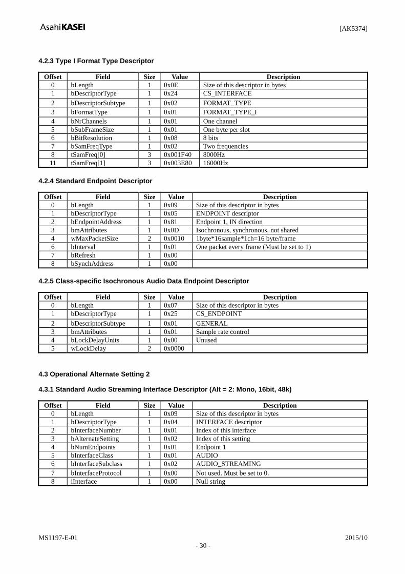
4.2.3 Type I Format Type Descriptor
Offset Field Size Value Description
0 bLength 1 0x0E Size of this descriptor in bytes
1 bDescriptorType 1 0x24 CS_INTERFACE
2 bDescriptorSubtype 1 0x02 FORMAT_TYPE
3 bFormatType 1 0x01 FORMAT_TYPE_I
4 bNrChannels 1 0x01 One channel
5 bSubFrameSize 1 0x01 One byte per slot
6 bBitResolution 1 0x08 8 bits
7 bSamFreqType 1 0x02 Two frequencies
8 tSamFreq[0] 3 0x001F40 8000Hz
11 tSamFreq[1] 3 0x003E80 16000Hz
4.2.4 Standard Endpoint Descriptor
Offset Field Size Value Description
0 bLength 1 0x09 Size of this descriptor in bytes
1 bDescriptorType 1 0x05 ENDPOINT descriptor
2 bEndpointAddress 1 0x81 Endpoint 1, IN direction
3 bmAttributes 1 0x0D Isochronous, synchronous, not shared
4 wMaxPacketSize 2 0x0010 1byte*16sample*1ch=16 byte/frame
6 bInterval 1 0x01 One packet every frame (Must be set to 1)
7 bRefresh 1 0x00
8 bSynchAddress 1 0x00
4.2.5 Class-specific Isochronous Audio Data Endpoint Descriptor
Offset Field Size Value Description
0 bLength 1 0x07 Size of this descriptor in bytes
1 bDescriptorType 1 0x25 CS_ENDPOINT
2 bDescriptorSubtype 1 0x01 GENERAL
3 bmAttributes 1 0x01 Sample rate control
4 bLockDelayUnits 1 0x00 Unused
5 wLockDelay 2 0x0000
4.3 Operational Alternate Setting 2
4.3.1 Standard Audio Streaming Interface Descriptor (Alt = 2: Mono, 16bit, 48k)
Offset Field Size Value Description
0 bLength 1 0x09 Size of this descriptor in bytes
1 bDescriptorType 1 0x04 INTERFACE descriptor
2 bInterfaceNumber 1 0x01 Index of this interface
3 bAlternateSetting 1 0x02 Index of this setting
4 bNumEndpoints 1 0x01 Endpoint 1
5 bInterfaceClass 1 0x01 AUDIO
6 bInterfaceSubclass 1 0x02 AUDIO_STREAMING
7 bInterfaceProtocol 1 0x00 Not used. Must be set to 0.
8 iInterface 1 0x00 Null string
[AK5374]
MS1197-E-01 2015/10
- 31 -
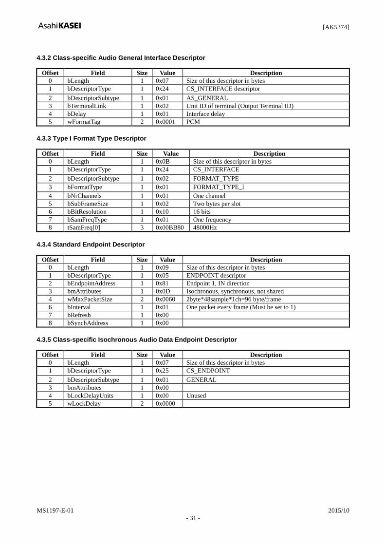
4.3.2 Class-specific Audio General Interface Descriptor
Offset Field Size Value Description
0 bLength 1 0x07 Size of this descriptor in bytes
1 bDescriptorType 1 0x24 CS_INTERFACE descriptor
2 bDescriptorSubtype 1 0x01 AS_GENERAL
3 bTerminalLink 1 0x02 Unit ID of terminal (Output Terminal ID)
4 bDelay 1 0x01 Interface delay
5 wFormatTag 2 0x0001 PCM
4.3.3 Type I Format Type Descriptor
Offset Field Size Value Description
0 bLength 1 0x0B Size of this descriptor in bytes
1 bDescriptorType 1 0x24 CS_INTERFACE
2 bDescriptorSubtype 1 0x02 FORMAT_TYPE
3 bFormatType 1 0x01 FORMAT_TYPE_I
4 bNrChannels 1 0x01 One channel
5 bSubFrameSize 1 0x02 Two bytes per slot
6 bBitResolution 1 0x10 16 bits
7 bSamFreqType 1 0x01 One frequency
8 tSamFreq[0] 3 0x00BB80 48000Hz
4.3.4 Standard Endpoint Descriptor
Offset Field Size Value Description
0 bLength 1 0x09 Size of this descriptor in bytes
1 bDescriptorType 1 0x05 ENDPOINT descriptor
2 bEndpointAddress 1 0x81 Endpoint 1, IN direction
3 bmAttributes 1 0x0D Isochronous, synchronous, not shared
4 wMaxPacketSize 2 0x0060 2byte*48sample*1ch=96 byte/frame
6 bInterval 1 0x01 One packet every frame (Must be set to 1)
7 bRefresh 1 0x00
8 bSynchAddress 1 0x00
4.3.5 Class-specific Isochronous Audio Data Endpoint Descriptor
Offset Field Size Value Description
0 bLength 1 0x07 Size of this descriptor in bytes
1 bDescriptorType 1 0x25 CS_ENDPOINT
2 bDescriptorSubtype 1 0x01 GENERAL
3 bmAttributes 1 0x00
4 bLockDelayUnits 1 0x00 Unused
5 wLockDelay 2 0x0000

[AK5374]
MS1197-E-01 2015/10
- 32 -
4.4 Operational Alternate Setting 3
4.4.1 Standard Audio Streaming Interface Descriptor (Alt = 3: Mono, 24bit, 32k/44.1k/48k)
Offset Field Size Value Description
0 bLength 1 0x09 Size of this descriptor in bytes
1 bDescriptorType 1 0x04 INTERFACE descriptor
2 bInterfaceNumber 1 0x01 Index of this interface
3 bAlternateSetting 1 0x03 Index of this setting
4 bNumEndpoints 1 0x01 Endpoint 1
5 bInterfaceClass 1 0x01 AUDIO
6 bInterfaceSubclass 1 0x02 AUDIO_STREAMING
7 bInterfaceProtocol 1 0x00 Not used. Must be set to 0.
8 iInterface 1 0x00 Null string
4.4.2 Class-specific Audio General Interface Descriptor
Offset Field Size Value Description
0 bLength 1 0x07 Size of this descriptor in bytes
1 bDescriptorType 1 0x24 CS_INTERFACE descriptor
2 bDescriptorSubtype 1 0x01 AS_GENERAL
3 bTerminalLink 1 0x02 Unit ID of terminal (Output Terminal ID)
4 bDelay 1 0x01 Interface delay
5 wFormatTag 2 0x0001 PCM
4.4.3 Type I Format Type Descriptor
Offset Field Size Value Description
0 bLength 1 0x11 Size of this descriptor in bytes
1 bDescriptorType 1 0x24 CS_INTERFACE
2 bDescriptorSubtype 1 0x02 FORMAT_TYPE
3 bFormatType 1 0x01 FORMAT_TYPE_I
4 bNrChannels 1 0x01 One channel
5 bSubFrameSize 1 0x03 Three bytes per slot
6 bBitResolution 1 0x18 24 bits
7 bSamFreqType 1 0x03 Three frequencies
8 tSamFreq[0] 3 0x007D00 32000Hz
11 tSamFreq[1] 3 0x00AC44 44100Hz
14 tSamFreq[2] 3 0x00BB80 48000Hz
4.4.4 Standard Endpoint Descriptor
Offset Field Size Value Description
0 bLength 1 0x09 Size of this descriptor in bytes
1 bDescriptorType 1 0x05 ENDPOINT descriptor
2 bEndpointAddress 1 0x81 Endpoint 1, IN direction
3 bmAttributes 1 0x0D Isochronous, synchronous, not shared
4 wMaxPacketSize 2 0x0090 3byte*48sample*1ch=144 byte/frame
6 bInterval 1 0x01 One packet every frame (Must be set to 1)
7 bRefresh 1 0x00
8 bSynchAddress 1 0x00

[AK5374]
MS1197-E-01 2015/10
- 33 -
4.4.5 Class-specific Isochronous Audio Data Endpoint Descriptor
Offset Field Size Value Description
0 bLength 1 0x07 Size of this descriptor in bytes
1 bDescriptorType 1 0x25 CS_ENDPOINT
2 bDescriptorSubtype 1 0x01 GENERAL
3 bmAttributes 1 0x01 Sample rate control
4 bLockDelayUnits 1 0x00 Unused
5 wLockDelay 2 0x0000
4.5 Operational Alternate Setting 4
4.5.1 Standard Audio Streaming Interface Descriptor (Alt = 4: St, 8bit, 8k/11.025k/16k/22.05k)
Offset Field Size Value Description
0 bLength 1 0x09 Size of this descriptor in bytes
1 bDescriptorType 1 0x04 INTERFACE descriptor
2 bInterfaceNumber 1 0x01 Index of this interface
3 bAlternateSetting 1 0x04 Index of this setting
4 bNumEndpoints 1 0x01 Endpoint 1
5 bInterfaceClass 1 0x01 AUDIO
6 bInterfaceSubclass 1 0x02 AUDIO_STREAMING
7 bInterfaceProtocol 1 0x00 Not used. Must be set to 0.
8 iInterface 1 0x00 Null string
4.5.2 Class-specific Audio General Interface Descriptor
Offset Field Size Value Description
0 bLength 1 0x07 Size of this descriptor in bytes
1 bDescriptorType 1 0x24 CS_INTERFACE descriptor
2 bDescriptorSubtype 1 0x01 AS_GENERAL
3 bTerminalLink 1 0x02 Unit ID of terminal (Output Terminal ID)
4 bDelay 1 0x01 Interface delay
5 wFormatTag 2 0x0002 PCM8
4.5.3 Type I Format Type Descriptor
Offset Field Size Value Description
0 bLength 1 0x14 Size of this descriptor in bytes
1 bDescriptorType 1 0x24 CS_INTERFACE
2 bDescriptorSubtype 1 0x02 FORMAT_TYPE
3 bFormatType 1 0x01 FORMAT_TYPE_I
4 bNrChannels 1 0x02 Two channels
5 bSubFrameSize 1 0x01 One byte per slot
6 bBitResolution 1 0x08 8 bits
7 bSamFreqType 1 0x04 Four frequencies
8 tSamFreq[0] 3 0x001F40 8000Hz
11 tSamFreq[1] 3 0x002B11 11025Hz
14 tSamFreq[2] 3 0x003E80 16000Hz
17 tSamFreq[3] 3 0x005622 22050Hz
[AK5374]
MS1197-E-01 2015/10
- 34 -
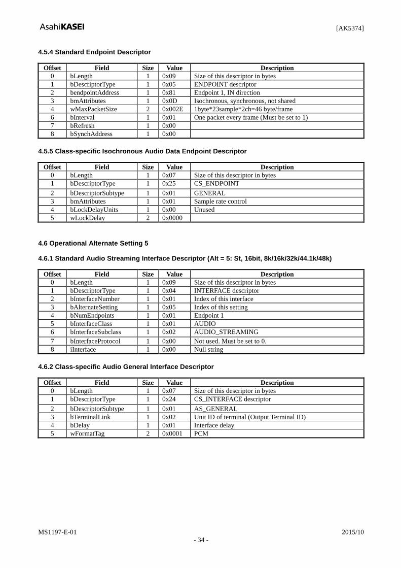
4.5.4 Standard Endpoint Descriptor
Offset Field Size Value Description
0 bLength 1 0x09 Size of this descriptor in bytes
1 bDescriptorType 1 0x05 ENDPOINT descriptor
2 bendpointAddress 1 0x81 Endpoint 1, IN direction
3 bmAttributes 1 0x0D Isochronous, synchronous, not shared
4 wMaxPacketSize 2 0x002E 1byte*23sample*2ch=46 byte/frame
6 bInterval 1 0x01 One packet every frame (Must be set to 1)
7 bRefresh 1 0x00
8 bSynchAddress 1 0x00
4.5.5 Class-specific Isochronous Audio Data Endpoint Descriptor
Offset Field Size Value Description
0 bLength 1 0x07 Size of this descriptor in bytes
1 bDescriptorType 1 0x25 CS_ENDPOINT
2 bDescriptorSubtype 1 0x01 GENERAL
3 bmAttributes 1 0x01 Sample rate control
4 bLockDelayUnits 1 0x00 Unused
5 wLockDelay 2 0x0000
4.6 Operational Alternate Setting 5
4.6.1 Standard Audio Streaming Interface Descriptor (Alt = 5: St, 16bit, 8k/16k/32k/44.1k/48k)
Offset Field Size Value Description
0 bLength 1 0x09 Size of this descriptor in bytes
1 bDescriptorType 1 0x04 INTERFACE descriptor
2 bInterfaceNumber 1 0x01 Index of this interface
3 bAlternateSetting 1 0x05 Index of this setting
4 bNumEndpoints 1 0x01 Endpoint 1
5 bInterfaceClass 1 0x01 AUDIO
6 bInterfaceSubclass 1 0x02 AUDIO_STREAMING
7 bInterfaceProtocol 1 0x00 Not used. Must be set to 0.
8 iInterface 1 0x00 Null string
4.6.2 Class-specific Audio General Interface Descriptor
Offset Field Size Value Description
0 bLength 1 0x07 Size of this descriptor in bytes
1 bDescriptorType 1 0x24 CS_INTERFACE descriptor
2 bDescriptorSubtype 1 0x01 AS_GENERAL
3 bTerminalLink 1 0x02 Unit ID of terminal (Output Terminal ID)
4 bDelay 1 0x01 Interface delay
5 wFormatTag 2 0x0001 PCM

[AK5374]
MS1197-E-01 2015/10
- 35 -
4.6.3 Type I Format Type Descriptor
Offset Field Size Value Description
0 bLength 1 0x17 Size of this descriptor in bytes
1 bDescriptorType 1 0x24 CS_INTERFACE
2 bDescriptorSubtype 1 0x02 FORMAT_TYPE
3 bFormatType 1 0x01 FORMAT_TYPE_I
4 bNrChannels 1 0x02 Two channel
5 bSubFrameSize 1 0x02 Two bytes per slot
6 bBitResolution 1 0x10 16 bits
7 bSamFreqType 1 0x05 Five frequencies
8 tSamFreq[0] 3 0x001F40 8000Hz
11 tSamFreq[1] 3 0x003E80 16000Hz
14 tSamFreq[2] 3 0x007D00 32000Hz
17 tSamFreq[3] 3 0x00AC44 44100Hz
20 tSamFreq[4] 3 0x00BB80 48000Hz
4.6.4 Standard Endpoint Descriptor
Offset Field Size Value Description
0 bLength 1 0x09 Size of this descriptor in bytes
1 bDescriptorType 1 0x05 ENDPOINT descriptor
2 bEndpointAddress 1 0x81 Endpoint 1, IN direction
3 bmAttributes 1 0x0D Isochronous, synchronous, not shared
4 wMaxPacketSize 2 0x00C0 2byte*48sample*2ch=192 byte/frame
6 bInterval 1 0x01 One packet every frame (Must be set to 1)
7 bRefresh 1 0x00
8 bSynchAddress 1 0x00
4.6.5 Class-specific Isochronous Audio Data Endpoint Descriptor
Offset Field Size Value Description
0 bLength 1 0x07 Size of this descriptor in bytes
1 bDescriptorType 1 0x25 CS_ENDPOINT
2 bDescriptorSubtype 1 0x01 GENERAL
3 bmAttributes 1 0x01 Sample rate control
4 bLockDelayUnits 1 0x00 Unused
5 wLockDelay 2 0x0000
4.7 Operational Alternate Setting 6
4.7.1 Standard Audio Streaming Interface Descriptor
(Alt = 6: St, 16bit, 8k/11.025k/16k/22.05k /32k/44.1k)
Offset Field Size Value Description
0 bLength 1 0x09 Size of this descriptor in bytes
1 bDescriptorType 1 0x04 INTERFACE descriptor
2 bInterfaceNumber 1 0x01 Index of this interface
3 bAlternateSetting 1 0x06 Index of this setting
4 bNumEndpoints 1 0x01 Endpoint 1
5 bInterfaceClass 1 0x01 AUDIO
6 bInterfaceSubclass 1 0x02 AUDIO_STREAMING
7 bInterfaceProtocol 1 0x00 Not used. Must be set to 0.
8 iInterface 1 0x00 Null string

[AK5374]
MS1197-E-01 2015/10
- 36 -
4.7.2 Class-specific Audio General Interface Descriptor
Offset Field Size Value Description
0 bLength 1 0x07 Size of this descriptor in bytes
1 bDescriptorType 1 0x24 CS_INTERFACE descriptor
2 bDescriptorSubtype 1 0x01 AS_GENERAL
3 bTerminalLink 1 0x02 Unit ID of terminal (Output Terminal ID)
4 bDelay 1 0x01 Interface delay
5 wFormatTag 2 0x0001 PCM
4.7.3 Type I Format Type Descriptor
Offset Field Size Value Description
0 bLength 1 0x1A Size of this descriptor in bytes
1 bDescriptorType 1 0x24 CS_INTERFACE
2 bDescriptorSubtype 1 0x02 FORMAT_TYPE
3 bFormatType 1 0x01 FORMAT_TYPE_I
4 bNrChannels 1 0x02 Two channels
5 bSubFrameSize 1 0x02 Two bytes per slot
6 bBitResolution 1 0x10 16 bits
7 bSamFreqType 1 0x06 Six frequencies
8 tSamFreq[0] 3 0x001F40 8000Hz
11 tSamFreq[1] 3 0x002B11 11025Hz
14 tSamFreq[2] 3 0x003E80 16000kHz
17 tSamFreq[3] 3 0x005622 22050Hz
20 tSamFreq[4] 3 0x007D00 32000Hz
23 tSamFreq[5] 3 0x00AC44 44100Hz
4.7.4 Standard Endpoint Descriptor
Offset Field Size Value Description
0 bLength 1 0x09 Size of this descriptor in bytes
1 bDescriptorType 1 0x05 ENDPOINT descriptor
2 bEndpointAddress 1 0x81 Endpoint 1, IN direction
3 bmAttributes 1 0x0D Isochronous, synchronous, not shared
4 wMaxPacketSize 2 0x00B4 2byte*45sample*2ch=180 byte/frame
6 bInterval 1 0x01 One packet every frame (Must be set to 1)
7 bRefresh 1 0x00
8 bSynchAddress 1 0x00
4.7.5 Class-specific Isochronous Audio Data Endpoint Descriptor
Offset Field Size Value Description
0 bLength 1 0x07 Size of this descriptor in bytes
1 bDescriptorType 1 0x25 CS_ENDPOINT
2 bDescriptorSubtype 1 0x01 GENERAL
3 bmAttributes 1 0x01 Sample rate control
4 bLockDelayUnits 1 0x00 Unused
5 wLockDelay 2 0x0000
[AK5374]
MS1197-E-01 2015/10
- 37 -
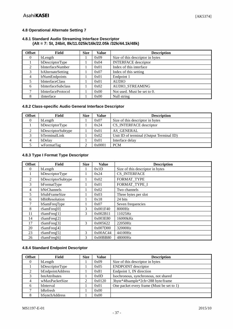
4.8 Operational Alternate Setting 7
4.8.1 Standard Audio Streaming Interface Descriptor
(Alt = 7: St, 24bit, 8k/11.025k/16k/22.05k /32k/44.1k/48k)
Offset Field Size Value Description
0 bLength 1 0x09 Size of this descriptor in bytes
1 bDescriptorType 1 0x04 INTERFACE descriptor
2 bInterfaceNumber 1 0x01 Index of this interface
3 bAlternateSetting 1 0x07 Index of this setting
4 bNumEndpoints 1 0x01 Endpoint 1
5 bInterfaceClass 1 0x01 AUDIO
6 bInterfaceSubclass 1 0x02 AUDIO_STREAMING
7 bInterfaceProtocol 1 0x00 Not used. Must be set to 0.
8 iInterface 1 0x00 Null string
4.8.2 Class-specific Audio General Interface Descriptor
Offset Field Size Value Description
0 bLength 1 0x07 Size of this descriptor in bytes
1 bDescriptorType 1 0x24 CS_INTERFACE descriptor
2 bDescriptorSubtype 1 0x01 AS_GENERAL
3 bTerminalLink 1 0x02 Unit ID of terminal (Output Terminal ID)
4 bDelay 1 0x01 Interface delay
5 wFormatTag 2 0x0001 PCM
4.8.3 Type I Format Type Descriptor
Offset Field Size Value Description
0 bLength 1 0x1D Size of this descriptor in bytes
1 bDescriptorType 1 0x24 CS_INTERFACE
2 bDescriptorSubtype 1 0x02 FORMAT_TYPE
3 bFormatType 1 0x01 FORMAT_TYPE_I
4 bNrChannels 1 0x02 Two channels
5 bSubFrameSize 1 0x03 Three bytes per slot
6 bBitResolution 1 0x18 24 bits
7 bSamFreqType 1 0x07 Seven frequencies
8 tSamFreq[0] 3 0x001F40 8000Hz
11 tSamFreq[1] 3 0x002B11 11025Hz
14 tSamFreq[2] 0x003E80 16000kHz
17 tSamFreq[3] 3 0x005622 22050Hz
20 tSamFreq[4] 0x007D00 32000Hz
23 tSamFreq[5] 3 0x00AC44 44100Hz
26 tSamFreq[6] 3 0x00BB80 48000Hz
4.8.4 Standard Endpoint Descriptor
Offset Field Size Value Description
0 bLength 1 0x09 Size of this descriptor in bytes
1 bDescriptorType 1 0x05 ENDPOINT descriptor
2 bEndpointAddress 1 0x81 Endpoint 1, IN direction
3 bmAttributes 1 0x0D Isochronous, synchronous, not shared
4 wMaxPacketSize 2 0x0120 3byte*48sample*2ch=288 byte/frame
6 bInterval 1 0x01 One packet every frame (Must be set to 1)
7 bRefresh 1 0x00
8 bSynchAddress 1 0x00

[AK5374]
MS1197-E-01 2015/10
- 38 -
4.8.5 Class-specific Isochronous Audio Data Endpoint Descriptor
Offset Field Size Value Description
0 bLength 1 0x07 Size of this descriptor in bytes
1 bDescriptorType 1 0x25 CS_ENDPOINT
2 bDescriptorSubtype 1 0x01 GENERAL
3 bmAttributes 1 0x01 Sample rate control
4 bLockDelayUnits 1 0x00 Unused
5 wLockDelay 2 0x0000
[AK5374]
MS1197-E-01 2015/10
- 39 -
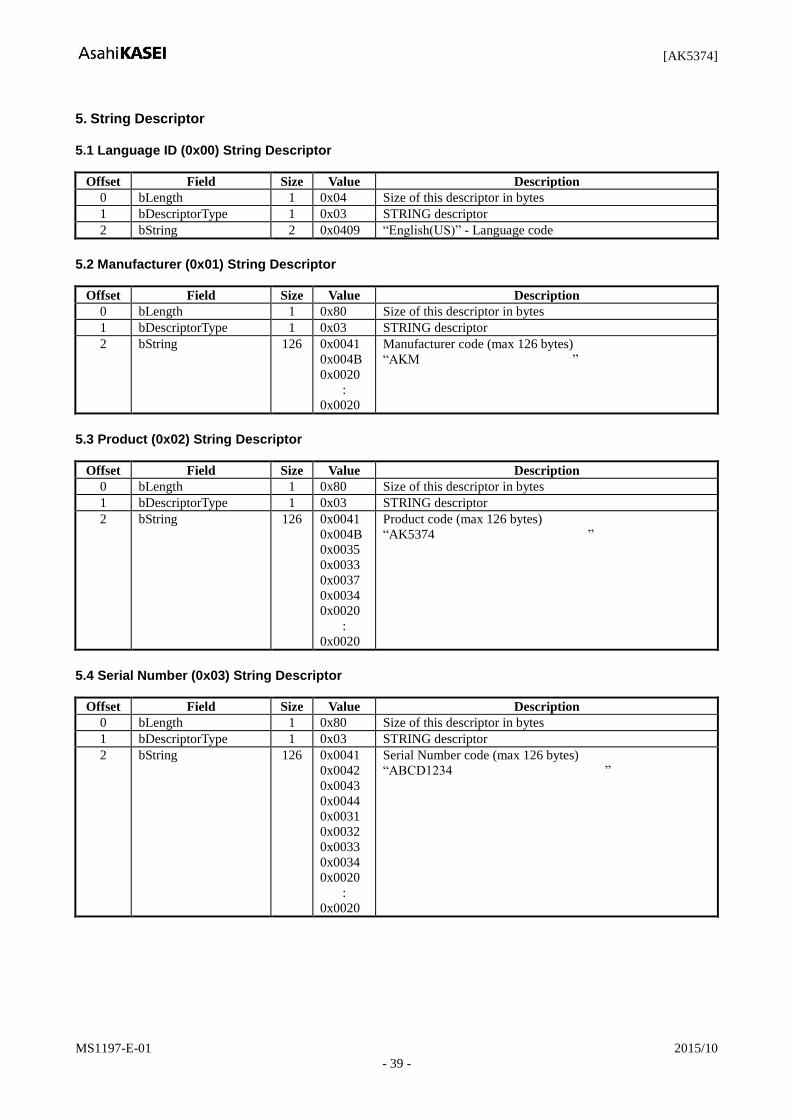
5. String Descriptor
5.1 Language ID (0x00) String Descriptor
Offset Field Size Value Description
0 bLength 1 0x04 Size of this descriptor in bytes
1 bDescriptorType 1 0x03 STRING descriptor
2 bString 2 0x0409 “English(US)” - Language code
5.2 Manufacturer (0x01) String Descriptor
Offset Field Size Value Description
0 bLength 1 0x80 Size of this descriptor in bytes
1 bDescriptorType 1 0x03 STRING descriptor
2 bString 126 0x0041
0x004B
0x0020
:
0x0020
Manufacturer code (max 126 bytes)
“AKM ”
5.3 Product (0x02) String Descriptor
Offset Field Size Value Description
0 bLength 1 0x80 Size of this descriptor in bytes
1 bDescriptorType 1 0x03 STRING descriptor
2 bString 126 0x0041
0x004B
0x0035
0x0033
0x0037
0x0034
0x0020
:
0x0020
Product code (max 126 bytes)
“AK5374 ”
5.4 Serial Number (0x03) String Descriptor
Offset Field Size Value Description
0 bLength 1 0x80 Size of this descriptor in bytes
1 bDescriptorType 1 0x03 STRING descriptor
2 bString 126 0x0041
0x0042
0x0043
0x0044
0x0031
0x0032
0x0033
0x0034
0x0020
:
0x0020
Serial Number code (max 126 bytes)
“ABCD1234 ”
[AK5374]
MS1197-E-01 2015/10
- 40 -
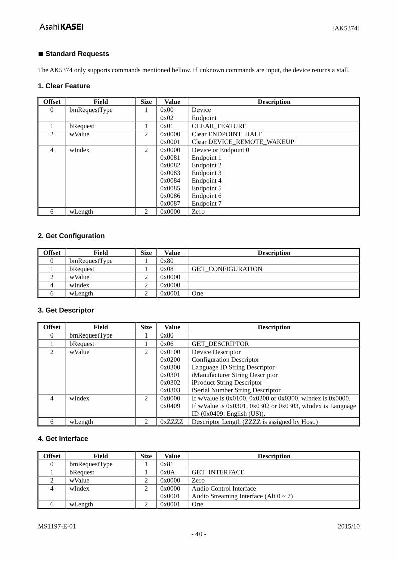
Standard Requests
The AK5374 only supports commands mentioned bellow. If unknown commands are input, the device returns a stall.
1. Clear Feature
Offset Field Size Value Description
0 bmRequestType 1 0x00
0x02
Device
Endpoint
1 bRequest 1 0x01 CLEAR_FEATURE
2 wValue 2 0x0000
0x0001
Clear ENDPOINT_HALT
Clear DEVICE_REMOTE_WAKEUP
4 wIndex 2 0x0000
0x0081
0x0082
0x0083
0x0084
0x0085
0x0086
0x0087
Device or Endpoint 0
Endpoint 1
Endpoint 2
Endpoint 3
Endpoint 4
Endpoint 5
Endpoint 6
Endpoint 7
6 wLength 2 0x0000 Zero
2. Get Configuration
Offset Field Size Value Description
0 bmRequestType 1 0x80
1 bRequest 1 0x08 GET_CONFIGURATION
2 wValue 2 0x0000
4 wIndex 2 0x0000
6 wLength 2 0x0001 One
3. Get Descriptor
Offset Field Size Value Description
0 bmRequestType 1 0x80
1 bRequest 1 0x06 GET_DESCRIPTOR
2 wValue 2 0x0100
0x0200
0x0300
0x0301
0x0302
0x0303
Device Descriptor
Configuration Descriptor
Language ID String Descriptor
iManufacturer String Descriptor
iProduct String Descriptor
iSerial Number String Descriptor
4 wIndex 2 0x0000
0x0409
If wValue is 0x0100, 0x0200 or 0x0300, wIndex is 0x0000.
If wValue is 0x0301, 0x0302 or 0x0303, wIndex is Language
ID (0x0409: English (US)).
6 wLength 2 0xZZZZ Descriptor Length (ZZZZ is assigned by Host.)
4. Get Interface
Offset Field Size Value Description
0 bmRequestType 1 0x81
1 bRequest 1 0x0A GET_INTERFACE
2 wValue 2 0x0000 Zero
4 wIndex 2 0x0000
0x0001
Audio Control Interface
Audio Streaming Interface (Alt 0 ~ 7)
6 wLength 2 0x0001 One
[AK5374]
MS1197-E-01 2015/10
- 41 -
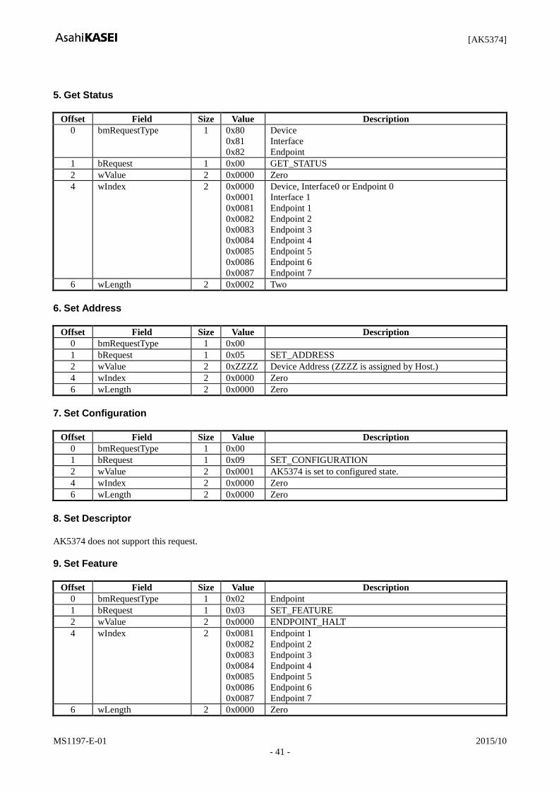
5. Get Status
Offset Field Size Value Description
0 bmRequestType 1 0x80
0x81
0x82
Device
Interface
Endpoint
1 bRequest 1 0x00 GET_STATUS
2 wValue 2 0x0000 Zero
4 wIndex 2 0x0000
0x0001
0x0081
0x0082
0x0083
0x0084
0x0085
0x0086
0x0087
Device, Interface0 or Endpoint 0
Interface 1
Endpoint 1
Endpoint 2
Endpoint 3
Endpoint 4
Endpoint 5
Endpoint 6
Endpoint 7
6 wLength 2 0x0002 Two
6. Set Address
Offset Field Size Value Description
0 bmRequestType 1 0x00
1 bRequest 1 0x05 SET_ADDRESS
2 wValue 2 0xZZZZ Device Address (ZZZZ is assigned by Host.)
4 wIndex 2 0x0000 Zero
6 wLength 2 0x0000 Zero
7. Set Configuration
Offset Field Size Value Description
0 bmRequestType 1 0x00
1 bRequest 1 0x09 SET_CONFIGURATION
2 wValue 2 0x0001 AK5374 is set to configured state.
4 wIndex 2 0x0000 Zero
6 wLength 2 0x0000 Zero
8. Set Descriptor
AK5374 does not support this request.
9. Set Feature
Offset Field Size Value Description
0 bmRequestType 1 0x02 Endpoint
1 bRequest 1 0x03 SET_FEATURE
2 wValue 2 0x0000 ENDPOINT_HALT
4 wIndex 2 0x0081
0x0082
0x0083
0x0084
0x0085
0x0086
0x0087
Endpoint 1
Endpoint 2
Endpoint 3
Endpoint 4
Endpoint 5
Endpoint 6
Endpoint 7
6 wLength 2 0x0000 Zero

[AK5374]
MS1197-E-01 2015/10
- 42 -
10. Set Interface
Offset Field Size Value Description
0 bmRequestType 1 0x01
1 bRequest 1 0x0B SET_INTERFACE
2 wValue 2 0x0000
0x0001
0x0002
0x0003
0x0004
0x0005
0x0006
0x0007
Zero-bandwidth Alternate Setting
Alternate Setting 1
Alternate Setting 2
Alternate Setting 3
Alternate Setting 4
Alternate Setting 5
Alternate Setting 6
Alternate Setting 7
4 wIndex 2 0x0000
0x0001
Audio Control Interface
Audio Streaming Interface
6 wLength 2 0x0000 Zero
11. Sync Frame
The AK5374 does not support this request.
[AK5374]
MS1197-E-01 2015/10
- 43 -
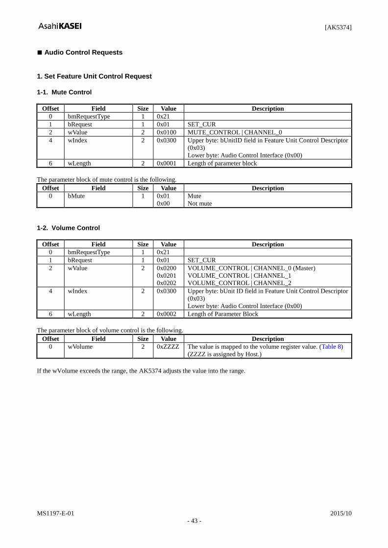
Audio Control Requests
1. Set Feature Unit Control Request
1-1. Mute Control
Offset Field Size Value Description
0 bmRequestType 1 0x21
1 bRequest 1 0x01 SET_CUR
2 wValue 2 0x0100 MUTE_CONTROL | CHANNEL_0
4 wIndex 2 0x0300 Upper byte: bUnitID field in Feature Unit Control Descriptor
(0x03)
Lower byte: Audio Control Interface (0x00)
6 wLength 2 0x0001 Length of parameter block
The parameter block of mute control is the following.
Offset Field Size Value Description
0 bMute 1 0x01
0x00
Mute
Not mute
1-2. Volume Control
Offset Field Size Value Description
0 bmRequestType 1 0x21
1 bRequest 1 0x01 SET_CUR
2 wValue 2 0x0200
0x0201
0x0202
VOLUME_CONTROL | CHANNEL_0 (Master)
VOLUME_CONTROL | CHANNEL_1
VOLUME_CONTROL | CHANNEL_2
4 wIndex 2 0x0300 Upper byte: bUnit ID field in Feature Unit Control Descriptor
(0x03)
Lower byte: Audio Control Interface (0x00)
6 wLength 2 0x0002 Length of Parameter Block
The parameter block of volume control is the following.
Offset Field Size Value Description
0 wVolume 2 0xZZZZ The value is mapped to the volume register value. (Table 8)
(ZZZZ is assigned by Host.)
If the wVolume exceeds the range, the AK5374 adjusts the value into the range.
[AK5374]
MS1197-E-01 2015/10
- 44 -
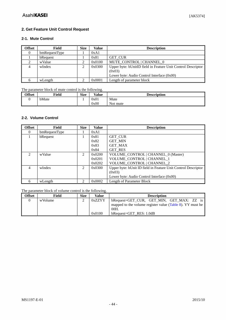
2. Get Feature Unit Control Request
2-1. Mute Control
Offset Field Size Value Description
0 bmRequestType 1 0xA1
1 bRequest 1 0x81 GET_CUR
2 wValue 2 0x0100 MUTE_CONTROL | CHANNEL_0
4 wIndex 2 0x0300 Upper byte: bUnitID field in Feature Unit Control Descriptor
(0x03)
Lower byte: Audio Control Interface (0x00)
6 wLength 2 0x0001 Length of parameter block
The parameter block of mute control is the following.
Offset Field Size Value Description
0 bMute 1 0x01
0x00
Mute
Not mute
2-2. Volume Control
Offset Field Size Value Description
0 bmRequestType 1 0xA1
1 bRequest 1 0x81
0x82
0x83
0x84
GET_CUR
GET_MIN
GET_MAX
GET_RES
2 wValue 2 0x0200
0x0201
0x0202
VOLUME_CONTROL | CHANNEL_0 (Master)
VOLUME_CONTROL | CHANNEL_1
VOLUME_CONTROL | CHANNEL_2
4 wIndex 2 0x0300 Upper byte: bUnit ID field in Feature Unit Control Descriptor
(0x03)
Lower byte: Audio Control Interface (0x00)
6 wLength 2 0x0002 Length of Parameter Block
The parameter block of volume control is the following.
Offset Field Size Value Description
0 wVolume 2 0xZZYY
0x0100
bRequest=GET_CUR, GET_MIN, GET_MAX: ZZ is
mapped to the volume register value (Table 8). YY must be
00H.
bRequest=GET_RES: 1.0dB
[AK5374]
MS1197-E-01 2015/10
- 45 -
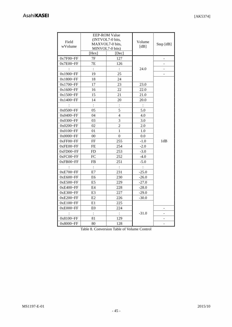
Field
wVolume
EEP-ROM Value
(INTVOL7-0 bits,
MAXVOL7-0 bits,
MINVOL7-0 bits)
Volume
[dB] Step [dB]
[Hex] [Dec]
0x7F00~FF 7F 127
24.0
-
0x7E00~FF 7E 126 -
: : : -
0x1900~FF 19 25 -
0x1800~FF 18 24
1dB
0x1700~FF 17 23 23.0
0x1600~FF 16 22 22.0
0x1500~FF 15 21 21.0
0x1400~FF 14 20 20.0
: : : :
0x0500~FF 05 5 5.0
0x0400~FF 04 4 4.0
0x0300~FF 03 3 3.0
0x0200~FF 02 2 2.0
0x0100~FF 01 1 1.0
0x0000~FF 00 0 0.0
0xFF00~FF FF 255 -1.0
0xFE00~FF FE 254 -2.0
0xFD00~FF FD 253 -3.0
0xFC00~FF FC 252 -4.0
0xFB00~FF FB 251 -5.0
: : : :
0xE700~FF E7 231 -25.0
0xE600~FF E6 230 -26.0
0xE500~FF E5 229 -27.0
0xE400~FF E4 228 -28.0
0xE300~FF E3 227 -29.0
0xE200~FF E2 226 -30.0
0xE100~FF E1 225
-31.0
0xE000~FF E0 224 -
: : : -
0x8100~FF 81 129 -
0x8000~FF 80 128 -
Table 8. Conversion Table of Volume Control

[AK5374]
MS1197-E-01 2015/10
- 46 -
Audio Endpoint Control Request
1. Set Endpoint Control Request
Offset Field Size Value Description
0 bmRequestType 1 0x22
1 bRequest 1 0x01 SET_CUR
2 wValue 2 0x0100 Upper byte: SAMPLING_FREQ_CONTROL (0x01)
Lower byte: Zero
4 wIndex 2 0x0081 Upper byte: Zero
Lower byte: Endpoint Address (0x81)
6 wLength 2 0x0003 Length of parameter block
The parameter block of mute control is the following.
Offset Field Size Value Description
0 iSampleFreq 3 0xYYYYYY 0x001F40: 8kHz
0x002B11: 11.025kHz
0x003E80: 16kHz
0x005622: 22.05kHz
0x007D00: 32kHz
0x00AC44: 44.1kHz
0x00BB80: 48kHz
2. Get Endpoint Control Request
Offset Field Size Value Description
0 bmRequestType 1 0xA2
1 bRequest 1 0x81 GET_CUR
2 wValue 2 0x0100 Upper byte: SAMPLING_FREQ_CONTROL (0x01)
Lower byte: Zero
4 wIndex 2 0x0081 Upper byte: Zero
Lower byte: Endpoint Address (0x81)
6 wLength 2 0x0003 Length of parameter block
The parameter block of mute control is the following.
Offset Field Size Value Description
0 iSampleFreq 3 0xYYYYYY 0x001F40: 8kHz
0x002B11: 11.025kHz
0x003E80: 16kHz
0x005622: 22.05kHz
0x007D00: 32kHz
0x00AC44: 44.1kHz
0x00BB80: 48kHz
[AK5374]
MS1197-E-01 2015/10
- 47 -
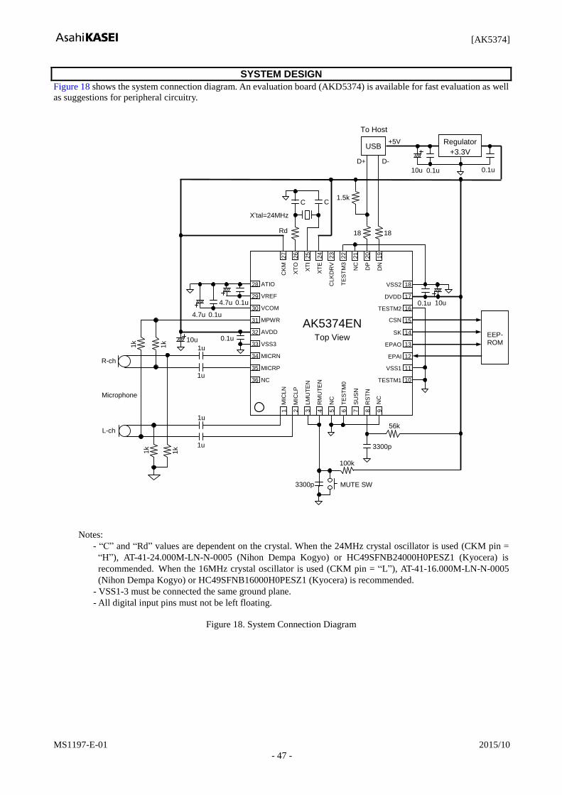
SYSTEM DESIGN
Figure 18 shows the system connection diagram. An evaluation board (AKD5374) is available for fast evaluation as well
as suggestions for peripheral circuitry.
1k
0.1u
EEP- ROM
10u
0.1u
Microphone
0.1u
0.1u 4.7u
4.7u
X’tal=24MHz
Rd
C C
1k
1k
1k
1u
1u
1u
1u 3300p
56k
3300p
100k
MUTE SW
0.1u 0.1u
+5V USB
18 18
1.5k
To Host
Regulator
+3.3V
D- D+
10u
R-ch
L-ch
10u
28
29
30
31
32
33
34
36
35
ATIO
VCOM
MPWR
AVDD
VSS3
MICRN
MICRP
NC
CK
M
XT
O
CL
KD
RV
TE
ST
M3
DP
MIC
LN
VSS2
1
2
3
4
5
6
7
8
9
RM
UT
EN
MIC
LP
LM
UT
EN
NC
TE
ST
M0
SU
SN
DVDD
TESTM2
CSN
SK
EPAO
EPAI
VSS1
AK5374EN
XT
I
XT
E
VREF
18
17
16
15
14
13
11
12
27
26
25
24
23
22
21
20
19
RS
TN
TESTM1 10 D
N
NC
Top View
NC
Notes:
- “C” and “Rd” values are dependent on the crystal. When the 24MHz crystal oscillator is used (CKM pin =
“H”), AT-41-24.000M-LN-N-0005 (Nihon Dempa Kogyo) or HC49SFNB24000H0PESZ1 (Kyocera) is
recommended. When the 16MHz crystal oscillator is used (CKM pin = “L”), AT-41-16.000M-LN-N-0005
(Nihon Dempa Kogyo) or HC49SFNB16000H0PESZ1 (Kyocera) is recommended.
- VSS1-3 must be connected the same ground plane.
- All digital input pins must not be left floating.
Figure 18. System Connection Diagram
[AK5374]
MS1197-E-01 2015/10
- 48 -
1. Grounding and Power Supply Decoupling
The AK5374 requires careful attention to power supply and grounding arrangements. AVDD and DVDD are usually
supplied from the system’s analog supply. If AVDD and DVDD are supplied separately, the power-up sequence is not
critical. VSS1-3 of the AK5374 must be connected to the analog ground plane. System analog ground and digital ground
must be connected together near to where the supplies are brought onto the printed circuit board. Decoupling capacitors
must be as near to the AK5374 as possible, with the small value ceramic capacitor being the nearest.
2. Voltage Reference
The voltage of VREF is 2.2V (typ) and set the analog input range. VCOM is 50%VREF and a signal ground of this chip.
A 4.7F electrolytic capacitor in parallel with a 0.1F ceramic capacitor attached to the VREF pin and the VCOM pin
eliminates the effects of high frequency noise. No load current may be drawn from the VREF pin and the VCOM pin. All
signals, especially clocks, should be kept away from the VREF pin and the VCOM pin in order to avoid unwanted
coupling into the AK5374.
3. Analog Inputs
The analog inputs are full-differential and input resistance is 20k (typ). The input signal range is typ. ±0.038Vpp
(@MGAIN = +30dB) and typ. ±1.2Vpp (@MGAIN = 0dB), centered around the internal common voltage (typ. 1.1V).
Usually the input signal is AC coupled using a capacitor. The cut-off frequency is fc = 1/ (2RC). The DC offset including
the ADC’s own DC offset is removed by the internal HPF (fc=0.93Hz@fs=48kHz). The AK5374 can accept input
voltages from VSS1 to VREF.

[AK5374]
MS1197-E-01 2015/10 - 49 -
PACKAGE
Outline Dimensions
36-pin QFN (Unit: mm)
0.4
0 ±
0.0
7
A
B
5.00 ± 0.07
5.0
0 ±
0.0
7
0.20 ± 0.05
36
C0.30
0.0
5M
AX
BOTTOM VIEW
0.05 C
3.62
3.6
2
0.40
0.05 M C A B
TOP VIEW
1 9
10
18
19 27
C
0.7
5M
AX
0.7
0
0.0
0 ~
0.0
5
(0.2
0)
0.20 ± 0.05
Part A [Part A detail]
Note: The exposed pad on the bottom surface of the package must be connected to the ground.
Material & Lead finish
Package molding compound: Epoxy Resin, Halogen (bromine and chlorine) free
Lead frame material: Cu Alloy
Pin surface treatment: Solder (Pb free) plate

[AK5374]
MS1197-E-01 2015/10 - 50 -
MARKING
5 3 7 4
1
X X X X X
XXXXX: Date code (5 digits)
Pin #1 indication

[AK5374]
MS1197-E-01 2015/10 - 51 -
REVISION HISTORY
Date (YY/MM/DD) Revision Reason Page/Line Contents
10/06/03 00 First Edition
15/10/30 01 Specification
Change
49, 50 PACKAGE, MARKING.
Package dimension and Marking were changed.
IMPORTANT NOTICE
0. Asahi Kasei Microdevices Corporation (“AKM”) reserves the right to make changes to the information contained in
this document without notice. When you consider any use or application of AKM product stipulated in this document
(“Product”), please make inquiries the sales office of AKM or authorized distributors as to current status of the
Products.
1. All information included in this document are provided only to illustrate the operation and application examples of
AKM Products. AKM neither makes warranties or representations with respect to the accuracy or completeness of the
information contained in this document nor grants any license to any intellectual property rights or any other rights of
AKM or any third party with respect to the information in this document. You are fully responsible for use of such
information contained in this document in your product design or applications. AKM ASSUMES NO LIABILITY
FOR ANY LOSSES INCURRED BY YOU OR THIRD PARTIES ARISING FROM THE USE OF SUCH
INFORMATION IN YOUR PRODUCT DESIGN OR APPLICATIONS.
2. The Product is neither intended nor warranted for use in equipment or systems that require extraordinarily high levels
of quality and/or reliability and/or a malfunction or failure of which may cause loss of human life, bodily injury,
serious property damage or serious public impact, including but not limited to, equipment used in nuclear facilities,
equipment used in the aerospace industry, medical equipment, equipment used for automobiles, trains, ships and other
transportation, traffic signaling equipment, equipment used to control combustions or explosions, safety devices,
elevators and escalators, devices related to electric power, and equipment used in finance-related fields. Do not use
Product for the above use unless specifically agreed by AKM in writing.
3. Though AKM works continually to improve the Product’s quality and reliability, you are responsible for complying
with safety standards and for providing adequate designs and safeguards for your hardware, software and systems
which minimize risk and avoid situations in which a malfunction or failure of the Product could cause loss of human
life, bodily injury or damage to property, including data loss or corruption.
4. Do not use or otherwise make available the Product or related technology or any information contained in this
document for any military purposes, including without limitation, for the design, development, use, stockpiling or
manufacturing of nuclear, chemical, or biological weapons or missile technology products (mass destruction
weapons). When exporting the Products or related technology or any information contained in this document, you
should comply with the applicable export control laws and regulations and follow the procedures required by such
laws and regulations. The Products and related technology may not be used for or incorporated into any products or
systems whose manufacture, use, or sale is prohibited under any applicable domestic or foreign laws or regulations.
5. Please contact AKM sales representative for details as to environmental matters such as the RoHS compatibility of the
Product. Please use the Product in compliance with all applicable laws and regulations that regulate the inclusion or
use of controlled substances, including without limitation, the EU RoHS Directive. AKM assumes no liability for
damages or losses occurring as a result of noncompliance with applicable laws and regulations.
6. Resale of the Product with provisions different from the statement and/or technical features set forth in this document
shall immediately void any warranty granted by AKM for the Product and shall not create or extend in any manner
whatsoever, any liability of AKM.
7. This document may not be reproduced or duplicated, in any form, in whole or in part, without prior written consent of
AKM.


![1. General description - nxp.com · 2-lane DisplayPort to VGA adapter IC [1] HVQFN48 package die supply ground is connected to both GND pins and exposed center pad. GND pins](https://img.pdfslide.net/doc/110x75/5b4c234e7f8b9afe4d8b6cdd/1-general-description-nxpcom-2-lane-displayport-to-vga-adapter-ic-1-hvqfn48.jpg)