Embed Size (px)
Citation preview
GENERALINFORMATION
Date:
Sheet:
Revisions
Mk Date Description
MAR. 04, 2016
15-019
Drawn: Check:
Job Number:
3 / 04 / 16
4921 F
OX
C
HA
SE
R
OA
D
GR
EE
NS
BO
RO
, N
OR
TH
C
AR
OLIN
A 27410
(336) 430-6684 engineerm
ike@
triad.rr.com
MIK
E N
. W
AG
ON
ER
P
.E
.
ST
RU
CT
UR
AL E
NG
IN
EE
R
RAH MNW
NC H
ighwa
y 135
Mayo
dan,
North
Car
olina
270
27
P A U LB R I G G SA R C H I T E C T
11500 S. HWY 8, SUITE CLEXINGTON, NC, 27292PHONE: 336-248-2030FAX: 336-248-6355
BUILDING CODE SUMMARY
STRUCTURAL DESIGN
DESIGN LOADS:Wind (I )Importance Factors: W
Snow (I )S
Seismic (I )E
111
Roof 20Live Loads: psfMezzanine N/A psfFloor 50 psf work space
20 psfGround Snow Load:
Wind Load: Basic Wind Speed 90 mph (ASCE-7)Exposure Category B
Wind Base Shears (for MWFRS) 42 V =V = 20
SEISMIC DESIGN CATEGORY: BA C DProvide the following Seismic Design Parameters:
(Table 1604.5)Occupancy CategorySpectral Response Acceleration %gS %gS 1S
III III IV
Site Classification (Table 1613.5.2) BA C D E FData Source: Field Test Presumptive Historical Data
Basic structural system (check one)Dual w/ Special Moment FrameBearing WallDual w/ Intermediate R/C or Special SteelBuilding FrameInverted PendulumMoment Frame
Seismic base shear: 19 V =V = 19
Analysis Procedure: Equivalent Lateral ForceSimplified DynamicArchitectural, Mechanical, Components anchored? NoYes
X Y
X Y
LATERAL DESIGN CONTROL: WindEarthquake
SOIL BEARING CAPACITIES:Field Test (provide copy of test report)Presumptive Bearing capacityPile size, type, and capacity
psf2,500 psf
N/A
SPECIAL INSPECTIONS REQUIRED: NoYes
K K
STRUCTURAL NOTES
1. SOIL BEARING TO BE 2,500 PSF.
2. THE 28-DAY COMPRESSIVE STRENGTH IS 3,000 PSI FOR ALL
FOOTINGS AND SLABS.
3. ALL REINFORCING STEEL TO BE ASTM A615 GRADE 60; LAP 24 BAR
MINIMUM UNLESS NOTED OTHERWISE.
4. REFERENCED FINISHED FLOOR ELEVATION: 710.0' UNLESS NOTED
OTHERWISE
5. THE FIRST FLOOR AND ATTIC FLOOR IS A STRUCTURAL DIAPHRAGM
AND PART OF THE LATERAL FORCE RESISTING SYSTEM.
6. ALL WALLS TO BE BRACED UNTIL ALL SYSTEMS ARE IN PLACE.
DRAWING INDEX
GENERAL INFORMATION
FOUNDATION PLAN
1st FLOOR FRAMING PLAN
ATTIC FRAMING PLAN
ROOF FRAMING PLAN
FOUNDATION DETAILS
FRAMING DETAILS
ATTIC FRAMING DETAILS
S0.0
S1.0
S1.1
S1.2
S1.3
S2.0
S3.0
S3.1
A. General Conditions
A1. The contractor is responsible for means and methods of construction to erect
the structure indicated on the drawings.
A2. The structure is designed to act in whole as a completed unit. The contractor
shall design and provide temporary bracing, shoring, and supports as required
until all structural elements are installed.
A3. The contractor shall notify the engineer of any deviations to be made from the
construction documents. Such notification shall be made in writing and clearly
identified if included on shop drawings/product data submittals. The contractor
shall not proceed with installation of alternate construction until receipt of written
confirmation of the change from the engineer.
A4. The contractor is responsible for the design of concrete formwork and
shoring.
A5. The contractor shall not impose loads on the structure during construction
that exceeds the capacity of the structure. Design loads are indicated on the
drawings.
A6. All structural openings for materials handling, conveying, mechanical,
electrical, and/or plumbing equipment shall be verified with the actual equipment
purchased before proceeding with the structural work.
B.
Foundation and Earthwork
B1. All footings shall be founded on solid undisturbed soil or on field controlled,
compacted fill. Footings bearing surfaces shall be mechanically tamped and
consolidated. A soil bearing pressure of 2,500 psf was used to design footings.
B2. If footing subgrade soils are wet, disturbed, unstable, or unsuitable material
the engineer shall be notified. Foundation excavations shall be cleared of all
debris, trash, and loose material prior to pouring concrete.
B3. Steps in wall footings shall not exceed a slope of one (1) vertical to two (2)
horizontal unless specifically noted otherwise on the drawings.
C. Concrete Work
C1. Concrete work shall comply with provisions of ACI 301 and ACI 318.
Concrete construction tolerances shall be as set forth in ACI 117. Provisions of
ACI 305 and/or ACI 306 shall apply as weather conditions warrant. Formwork
shall be in compliance with provisions of ACI 347.
C2. Unless otherwise shown on drawings, minimum cover for reinforcing steel
shall be as follows:
Concrete cast against earth .............................................................. 3"
Walls and piers (over vertical reinforcing) ........................................ 2"
C3. All reinforcing shall be held securely in position with standard accessories
during concrete placement in conformance with the provisions of the CRSI
manual of Standard Practice and ACI 315. Reinforcing steel shall be clean of
dirt, mud, hardened cementations materials, rust, grease or oil, or other matter
which may prevent proper bond and development.
C4. Unless otherwise noted, splices in reinforcing where permitted shall be as
follows:
Deformed reinforcing bars ............................................. 24 bar diameters
Welded wire fabric .......................................................... 6 inch overlap
C5. All hooks in reinforcing bars shall be ACI standard hooks unless otherwise
shown or noted on the drawings.
C6. Ready mixed concrete shall conform to ASTM C94 and ACI 304. Concrete
shall be placed as near as practicable to its final location. Concrete shall not be
allowed to fall freely for a height of more than 4 feet. Concrete shall be
consolidated to prevent voids and honeycombs. Concrete vibrators shall not be
used to move concrete to its final location.
C7. Concrete shall be placed continuously to prevent cold joints in the work.
Should a disruption occur during placement the work shall be stopped and a
construction joint installed.
C8. Concrete shall be cured using wet curing or curing compounds for the
durations stipulated in the ACI building code.
D Steel Work
D1. Block to comply with ASTM C90 type II with a compressive strength of 1,500
psi.
D2. Bond beams, pilasters, retaining walls, shear walls and all other reinforced
brick walls shall be poured with high slump, pea gravel, concrete grout mix with a
compressive strength of 3,000 psi in 28 days.
D3. Cement-lime mortar shall be type "S" with a minimum compressive strength
of 1,800 psi in 28 days.
E Steel Work
E1. Structural steel shall be primed with gray primer
E2. All angles, bars, anchors, anchor bolts, etc. embedded in concrete that are
exposed to weather or view shall be hot-dipped galvanized after fabrication
E3. All bolts shall be ¾ inch diameter, ASTM a325, unless otherwise
E4. High strength bolts not designated as slip critical (SC) may be installed snug
tight as per AISC specifications for structural joints using ASTM 325 or A490 bolts,
section SC
E5. Minimum size of all fillet welds shall conform to section J2.2b AISC
specifications even though shown otherwise on architectural or structural drawings
E6. All welds along the length of members indicated on architectural or structural
drawings but not sized shall be a minimum of 3/16" fillet, 2" at 12" c-c, both sides.
E7. All weld material and procedures shall conform to AWS D1.1 welds to primary
members shall be made with E70xx electrodes.
E8. See architectural, mechanical, electrical, and plumbing drawings for openings,
sleeves, etc. not shown on the structural drawings.
E9. All metal stud for first floor wall shall be 18 gage 6" CSJ spaced at 16" o.c.
with 18 ga. bottom and top track. See sections for attachment requirements at
shear walls.
F Structural Wood
F1. All wood construction shall be in accordance with State and Local Codes,
Industry's standard of good workmanship, and the plans. Wood for general use,
joist, headers, etc. shall conform to the National Design Specifications for Wood
Construction (NDS) and be grade mark No. 2 K.D. Southern Yellow Pine, or
better. Wood studs use shall conform to (NDS) and shall be grade marked #2
K.D. Spruce-Pine-Fir or better unless noted on plans.
F2. All wood plates, sills, beams, columns, etc. resting on concrete or masonry
shall be pressure treated wood as per the AWPI Specifications and NC State
Building Code.
F3. Roof sheathing shall be 5/8” CDX plywood. Attached to roof structure with
10d nails at 6” c/c at all supported edges & 12” c/c along intermediate support
members in center of building. Attached to roof structure with 10d nails at 4” c/c at
all supported edges & 4” c/c along intermediate support members within 8 feet of
perimeter of building and building ridge. All edges shall be blocked within 4' of
edge of building.
F4. All plywood shall be identified with a grade-trademark as per the latest APA
Specifications. Panel thickness, grade, and group number, span index or
identification index shall be equal to or better than the recommendations of the
APA in the Plywood Construction Guide.
F5. Metal connectors shall be Simpson, model number shown on plans.
Connectors shall be installed according to the manufacturer's specifications and
recommendations and per the NC State Building Code.
F6. An Engineer registered in the state of North Carolina shall design roof
trusses. Sealed design drawings shall be submitted for approval. Design of wood
trusses, including bracing and all necessary framing for roof mounted equipment
shall be provided by the truss manufacturer and shall conform to the following
minimum loading:
Roof:
i.Live Load………………… 20 psf
ii. Dead Load, top chord…….10 psf
iii. Dead Load, bottom chord.. 10 psf
iv. Total Truss Loading………40 psf
F7. Limit roof truss live load deflection to L/360.
F8. Provide all temporary and permanent truss bracing as per truss
manufacturer's requirements.
F9. Provide all temporary and permanent truss bracing as per truss
manufacturer's requirements
F10. Limit roof truss live load deflection to L/360.
F11. Trusses to be designed to resist a net uplift of 15 psf.
G Cold Formed Metal
G1. All studs and accessories shall conform to the type, size, gauge and spacing
shown on the drawings and shall be manufactured by Marino-Ware or approved
equal. Structural studs and joists shall conform to the Marino-Ware SW series
with 1 5/8” widths
G2. All structural members shall be designed and fabricated in accordance with
the American Iron and Steel Institute (AISI) “Specifications for the Design of
Cold-Formed Steel Structural Members”.
G3. All structural members shall be formed from corrosion-resistant steel
corresponding to the requirements of ASTM A446, with a minimum yield of 33 ksi
(50 ksi for 18 ga. Material and thicker) and shall have a zinc coating meeting
ASTM A525 requirements.
100 psf lobby and atticFloor

FOUNDATION PLAN1SCALE: 3/16"=1'-0"
8"
57
'-9
1
2"
8"
8"
38'-10
3
4"
8"
24'-0"
8"
38'-10
3
4"
8"
4'-6" 6'-4" 13'-2"
29
'-1
0
3
4"
8"
29
'-2
3
4"
29
'-1
0
3
4"
8"
23
'-8
"2
'-6
3
4"
3'-0
"
A
E
10
1
1
E
A
DD
C
C.1
C
B
A.9
B.6
-
32 4 5 7 8 8.2 96 6.3
32 4 5 7 8 8.2 96 6.3
B.7
B
1
S2.0
3
S2.0
4
S2.0
2
S2.0
6
S2.0
8" C.M.U. (TYPICAL
BELOW GRADE)
12" C.M.U. (TYPICAL
BELOW GRADE)U BLOCK LINTEL w/ (2)
#4 BARS IN BOTTOM
CRAWL SPACE GRADE
EL. 704.00'
CRAWL SPACE GRADE
EL. 707.00' ±
CRAWL SPACE GRADE
EL. 706.00' ±
CRAWL SPACE GRADE
EL. VARIES
8.1
B.9
ALL COLUMNS ARE TS 4x4x1/4 w/ 10"x10"x1/2" BASE PLATE.
ELEVATION OF TOP OF PIERS = 706.5'
ELEVATIONS OF FOOTINGS ARE SHOWN ( )
NO PIERS REQUIRED IN MECHANICAL ROOM
SEE APPROXIMATE GRADES OF CRAWL SPACE
F1
F2
F1
F2
F1 F1 F1
F1
F2
F1
F1 F1
F2
F4 F4
25
'-4
"
F3
F3
F3 F3 F3 F3 F3 F3
F3
F3
F3
F3
MECHANICAL ROOM FLOOR
EL. 701.47
4.6 6.2
2
S1.0
3
S2.0
3
S2.0
3
S2.0
(-72")
3
S2.0
(703.64') (702.32') (701.4') (700.97') (701.64') (702.31') (703.64')
(7
04
.6
4')
1
S2.0
(706.97')
(706.97')
(7
04
.6
4')
70
0.9
7'
70
0.9
7'
(704.0') (704.75')
PIERS ARE:
12" x 12" x (SEE PLAN FOR
HEIGHT) REINFORCE w/ (4) #4
VERTICAL DOWELS w/ #3 TIES
AT 12" O.C.
(SEE PLAN FOR LENGTH OF
DOWEL)
12
SE
E P
LA
N
TYPICAL PIER REINFORCING
8.1
B.4
B.6
B.8
(7
04
.3
1')
(7
04
.6
4')
(7
04
.9
7')
(7
06
.3
')
(7
06
.9
7')
(706.97')
(7
06
.9
7')
(7
06
.3
')
(7
04
.9
7')
(704.75')
(704.75')
(7
04
.3
1')
2
S1.0
(700.97')
(700.97')
(704.0')(704.75')
(704.75')
ALL FOOTING ELEVATIONS
ARE (705.0' ±) UNLESS
NOTED OTHERWISE
4
S2.0
(708.0') (708.0')
8" C.M.U.
SIM.
18'-9
5
8"16'-8" 11'-9
1
8" 10'-8" 12'-6
1
4" 12'-4
1
4" 12'-1
1
2"9'-6
3
4"
21
'-9
7
8"
10
'-0
"1
0'-0
"
17
'-3
5
8"
13
'-1
1"
10
'-7
1
2"
17
'-3
3
8"
17
'-3
5
8"
STONE FACE
STONE FACE
W10x17
(704.75')
104'-5
1
2" OUT TO OUT C.M.U.
1'-1
1
1
4"
5
8"
5
8"
9'-2
1
4" 9'-7
3
8" 16'-2" 12'-3
1
8" 7'-9
5
8" 12'-4
1
4" 3'-2
1
8"
1'-0"
7'-11
3
8" 9'-6
3
4"
59
'-1
1
2" O
UT
T
O O
UT
C
.M
.U
.
5
8"
13
'-1
1"
7'-1
0
7
8"
7
5
8"
1'-0
3
4"
7'-3
5
16"
10
'-0
"1
7'-3
5
8"
5
8"
TO
C
.M
.U
.T
O C
.M
.U
.
TO C.M.U.TO C.M.U.
9'-6
1
8"9'-1
5
8"
9'-1
1
2" 6'-3
1
8"
59
'-1
1
2" O
UT
T
O O
UT
C
.M
.U
.
8"
57
'-9
1
2"
8"
13
'-1
1"
8'-6
1
2"
1'-0
3
4"
4
5
8"
7'-1
0
15
16"
2'-1
1
16"
7'-1
0
15
16"
2'-1
"1
5'-2
5
8"
TO
C
.M
.U
.
13
'-1
0
3
8"
15
'-2
"
TO
C
.M
.U
.
5
8"
5
8"
104'-5
1
2" OUT TO OUT C.M.U.
8"
46'-0"8"
10'-5
1
2" 8" 24'-0"8"
10'-10
1
2"8"
9'-1
1
2"8"
9'-2
1
4" 9'-7
3
8" 16'-2" 8'-1
1
8" 4'-2" 7'-9
5
8" 6'-8
3
8" 2'-5
1
8" 6'-3
1
8" 12'-4
1
4" 3'-2
1
8"
1'-0"
7'-11
3
8" 9'-6
3
4" TO C.M.U.TO C.M.U.
5
8"
9'-1
5
8" 9'-6
1
8"
5
8"
5'-4
"
5'-8
"
8"
46'-8" 11'-9
1
2" 24'-8" 10'-10
1
2" 10'-5
1
2"
43'-0
3
4" 18'-8" 42'-8
3
4" TO C.M.U.TO C.M.U.
F3
CRAWL SPACE GRADE
EL. 706.00'
46'-0" TO C.M.U.
TO C.M.U.
SIM.
1
S2.0
5
S2.0
4
"
x
4
"
x
1
/
4
"
P
O
S
T
4
"
x
4
"
x
1
/
4
"
P
O
S
T
11'-1
1
2"
4
"
x
4
"
x
1
/
4
"
P
O
S
T
4
"
x
4
"
x
1
/
4
"
P
O
S
T
11'-5"
C
L
C
L
C
L
C
L
3
S2.0
(704.64')
COLUMING BASE
PLATE BEARING
AT 709'-1 1/8"
CRAWL SPACE GRADE
EL. 705.00' ±
SIM. SIM.
B.8
1'-0
1
4"
9'-4
3
8"
2SCALE: 1 1/2"=1'-0"
4"
1'-0
"
7"
12" x 12"
PIER
TS 4" x 4"
COLUMN
BASE PLATE IS
1/2" x 10" x 10" w/
(4) 3/4" ANCHOR
RODS
3/16 3"
FOUR
SIDES
T/ PIER
EL. 706.5'
FOUNDATIONPLAN
Date:
Sheet:
Revisions
Mk Date Description
MAR. 04, 2016
15-019
Drawn: Check:
Job Number:
3 / 04 / 16
4921 F
OX
C
HA
SE
R
OA
D
GR
EE
NS
BO
RO
, N
OR
TH
C
AR
OLIN
A 27410
(336) 430-6684 engineerm
ike@
triad.rr.com
MIK
E N
. W
AG
ON
ER
P
.E
.
ST
RU
CT
UR
AL E
NG
IN
EE
R
RAH MNW
NC H
ighwa
y 135
Mayo
dan,
North
Car
olina
270
27
P A U LB R I G G SA R C H I T E C T
11500 S. HWY 8, SUITE CLEXINGTON, NC, 27292PHONE: 336-248-2030FAX: 336-248-6355
FOOTING SCHEDULE
MARK SIZE REINFORCING COMMENTS
(5) #5 EACH WAY
(4) #5 EACH WAY TOP AND BOTTOM
(4) #5 EACH WAYF2
F3
-
-
-
-
4'-0" x 4'-0" x 1'-2"
F4
F1
REQ'D.
4
13
2
9
(3) #5 EACH WAY
5'-0" x 5'-0" x 1'-2"
4'-0" x 4'-0" x 2'-0"
3'-0" x 3'-0" x 1'-2"

FLOOR FRAMING PLAN1SCALE: 3/16"=1'-0"
A
E
10
1
1
E
A
DD
C
C.1
C
B
A.9
B.6
-
32 4 5 7 8 8.2 96 6.3
32 4 5 7 8 8.2 96 6.3
B.7
B
SHEAR WALL
FINISH FLOOR
ELEVATION: 710.00'
8.1
SHEAR WALL
B.9
59
'-0
1
4" O
UT
T
O O
UT
M
ET
AL
S
TU
DS
21
'-9
1
4"
7
5
8"
19
'-4
3
8"
17
'-3
"
59
'-0
1
4" O
UT
T
O O
UT
M
ET
AL
S
TU
DS
13
'-1
0
3
8"
8'-6
1
2"
19
'-4
3
8"
17
'-3
"
9'-1
1
15
16"
19
'-1
1
15
16"
15
'-2
"
9'-1
1
15
16"
10
'-0
"
2'-1
"1
'-5
7
16"
1'-0
3
4"
4
5
8"
10
'-7
1
2"
1'-0
3
4"
7
5
8"
10
'-0
"
4.6 6.2
104'-4
1
4" OUT TO OUT METAL STUDS
104'-4
1
4" OUT TO OUT METAL STUDS
9'-1
5
8" 9'-7
3
8" 16'-8" 11'-9
1
8" 7'-9
5
8" 9'-1
1
2" 6'-3
1
8" 12'-4
1
4" 4'-2
1
8" 7'-11
3
8" 9'-6
1
8"
9'-1
5
8" 9'-7
3
8" 16'-8" 11'-9
1
8" 7'-9
5
8" 9'-1
1
2" 6'-3
1
8" 12'-4
1
4" 4'-2
1
8" 7'-11
3
8" 9'-6
1
8"
5'-4
"
43'-0
1
8" 18'-8"
42'-8
1
8"
46'-8" 11'-8
1
4"24'-8"
10'-11
3
4" 10'-4
1
4"
1) 5/8" UNDERLAYMENT
2) 3/4" TONGUE AND GROOVE SUB FLOORING
FLOOR CONSTRUCTION
8.1
B.4
B.6
B.8
5
S3.0
1
S3.0
3
S2.0
11
S3.0
5
S3.0
W10x12 W10x12
W10x12W10x22W10x12 W10x22 W10x22 W10x12
W10x22
W10x19
* W
10
x1
7
W10x15 W10x12 W10x12 W10x15 W10x12
W10x15
W1
0x1
2
W10x17 W10x12 W10x12 W10x17 W10x12 W10x12 W10x12
10
T
JI 2
10
12 T
JI 110 A
T 1
6"
O.C
.
W1
0x1
2
W10x17 W10x12
W10x12W10x12W10x17
10 T
JI 210 A
T 1
6"
O.C
.
10 T
JI 230 A
T 1
2"
O.C
.
10 TJI 1
10 AT 1
6" O.C
.
10 T
JI 110 A
T 1
6"
O.C
.
10 T
JI 230 A
T 1
6"
O.C
.
10 T
JI 110 A
T 1
6"
O.C
.
10 T
JI 110 A
T 1
6"
O.C
.
W10x12
1
S2.0
14
S3.0
12
S3.0
12
S3.0
W1
0x1
2
14
S3.0
W1
0x1
2
5
S3.0
1
S2.0
9
S2.0
11
S2.0
3
S2.0
3
S2.0
3
S2.0
9
S2.0
1
S2.0
SHEAR WALL
SHEAR WALL
SHEAR WALL
SIM. SIM.
5
S2.0
4
"
x
4
"
x
1
/
4
"
P
O
S
T
4
"
x
4
"
x
1
/
4
"
P
O
S
T
4
"
x
4
"
x
1
/
4
"
P
O
S
T
7
S3.1
1
S2.0
SLAB ON
GRADE
4
"
x
4
"
x
1
/
4
"
P
O
S
T
SIM.
1
S2.0
SHEAR WALL
SHEAR WALL
DIAGONAL
BRACE
4
"
x
4
"
x
1
/
4
"
P
O
S
T
4
"
x
4
"
x
1
/
4
"
P
O
S
T
DIAGONAL
BRACE
5
S3.0 6
S3.1
6
S3.1
6
S3.1
4
"
x
4
"
x
1
/
4
"
P
O
S
T
* DO NOT USE WOOD NAILER
* W
10
x1
7
* W
10
x1
7
B.8
1'-0
1
4"
FIRST FLOORFRAMING PLAN
Date:
Sheet:
Revisions
Mk Date Description
MAR. 04, 2016
15-019
Drawn: Check:
Job Number:
3 / 04 / 16
4921 F
OX
C
HA
SE
R
OA
D
GR
EE
NS
BO
RO
, N
OR
TH
C
AR
OLIN
A 27410
(336) 430-6684 engineerm
ike@
triad.rr.com
MIK
E N
. W
AG
ON
ER
P
.E
.
ST
RU
CT
UR
AL E
NG
IN
EE
R
RAH MNW
NC H
ighwa
y 135
Mayo
dan,
North
Car
olina
270
27
P A U LB R I G G SA R C H I T E C T
11500 S. HWY 8, SUITE CLEXINGTON, NC, 27292PHONE: 336-248-2030FAX: 336-248-6355

ATTIC FRAMING PLAN1SCALE: 3/16"=1'-0"
A
E
10
1
1
E
A
DD
C
C.1
C
B
A.9
B.6
-
32 4 5 7 8 8.2 96 6.3
32 4 5 7 8 8.2 96 6.3
B.7
B
W10x22 W10x39 W10x26 W10x17 W10x39 W10x39 W10x17
W1
0x1
7W
10
x1
7W
10
x2
2
W10x12W10x26W10x39
* W
10
x2
6
W10x12W10x22
* W
10
x2
6
W10x39
* W
10
x2
6
W10x22
W1
0x1
7W
10
x1
7
1
2
T
J
I 1
1
0
A
T
1
2
" O
.C
.
1
2
T
J
I
1
1
0
A
T
1
2
"
O
.
C
.
1
2
T
J
I 3
6
0
A
T
1
2
"
O
.C
.
8.1
W10x15
B.9
59
'-0
1
4" O
UT
T
O O
UT
M
ET
AL
S
TU
DS
29
'-6
1
8"
29
'-6
1
8"
RID
GE
11
'-4
5
8"
36
'-3
"1
1'-4
5
8"
21
'-9
1
4"
7
5
8"
19
'-4
3
8"
17
'-3
"
13
'-1
0
3
8"
8'-6
1
2"
19
'-4
3
8"
17
'-3
"
9'-7
1
4"
20
'-4
5
8"
15
'-2
"
10
'-4
5
8"
10
'-0
"
2'-1
"1
'-0
3
4"
W1
0x1
2
10
'-7
9
16"
1'-0
3
4"
7
5
8"
10
'-0
"
W10x15
10'-7"
W10x15
JOIST
HEADER
JOIST
HEADER
4.6 6.2
(
2
)
2
x
1
0
(
2
)
2
x
1
0
104'-4
1
4" OUT TO OUT METAL STUDS
104'-4
1
4" OUT TO OUT METAL STUDS
9'-1
5
8" 9'-7
3
8" 16'-2" 12'-3
1
8" 7'-9
5
8" 9'-1
1
2" 6'-3
1
8" 12'-4
1
4" 4'-2
1
8" 7'-11
3
8" 9'-6
1
8"
9'-1
5
8" 9'-7
3
8" 16'-2" 12'-3
1
8" 7'-9
5
8" 9'-1
1
2" 6'-3
1
8" 12'-4
1
4" 4'-2
1
8" 7'-11
3
8" 9'-6
1
8"
43'-0
1
8" 18'-8" 42'-8
1
8"
46'-8" 11'-8
1
4" 24'-8" 10'-11
3
4" 10'-4
1
4"
5'-4
"
SHEAR WALL
1
S3.0
2
S3.0
STAIR
OPENING
(DJ)
HIP AND RIDGE
LINES (ABOVE)
SHEAR WALL (TYPICAL)
SHEAR WALL (TYPICAL)
STAIR
OPENING
W1
0x1
5
W1
0x1
5
W8x10
W8x10
30'-9
1
2" ±13'-0" ±
7'-1" ±
3'-6" ±
8'-9" ±
CL
EA
R
26'-6" ±
TJI JOISTS ARE SPACED AT 12" O.C. UNLES NOTED
LBW & SHEAR WALL
1
2
T
J
I
1
1
0
A
T
1
2
"
O
.
C
.
(D
J)
(D
J)
12 T
JI 360 A
T 1
2"
O.C
.
(D
J)
1
2
T
J
I
1
1
0
A
T
1
2
"
O
.
C
.
LBW = LOAD BEARING WALL BELOW
(DJ) = DOUBLE JOIST
LBW & SHEAR WALL
LBW
LBW
1
2
T
J
I
2
1
0
A
T
1
2
"
O
.
C
.
(D
J)
12 T
JI 560 A
T 1
2"
O.C
.
7
S3.0
1
0
T
J
I
1
1
0
1
4
T
J
I
1
1
0
3
S3.0
1
0
T
J
I
1
1
0
A
T
1
2
"
O
.
C
.
1
0
T
J
I
1
1
0
A
T
1
2
"
O
.
C
.
3
S3.0
(D
J)
1
2
T
J
I 3
6
0
A
T
1
2
"
O
.C
.
8.1
B.4
B.6
B.8
6
S3.0
22
'-4
7
8"
(DJ)
1
2
T
J
I 1
1
0
A
T
1
2
"
O
.
C
.
W1
0x1
2
A
T
1
2
"
O
.
C
.
10TJI 110
AT 12" O.C.
1
2
T
J
I
3
6
0
A
T
1
2
"
O
.
C
.
81'-1"
DO
UB
LE
JO
IS
TS
THREE 8" WIDE DUCT
OPENING LOCATIONS PER
H.V.A.C. CONTRACTOR
1'-8"
1'-10"
1'-8
"
1'-6"
1'-6"
1'-8
"
1'-10"
1'-10"
1'-10"
8"
LOAD BEARING WALL
LOAD BEARING WALL
6
S3.0
W1
0X
12
10
S3.0
10
S3.0
8
S3.0
8
S3.0
WS
TR
UT
W1
0X
12
ST
RU
T
W10x12 STRUT - NO NAILER REQ'D.
(NOT TOBE USED AS FLOOR JOIST)
- TYPICAL.
W1
0X
12
WS
TR
UT
W1
0X
12
WS
TR
UT
W1
0X
12
WS
TR
UT
W1
0X
12
WS
TR
UT
8'-6
9
16"
1'-0
9
16"
11'-7
3
4" ±11'-7
3
4" ±
4'-2
1
8" 8'-9
7
8"
16'-8" 11'-9
1
8" 7'-9
5
8"
11
S3.0
1
S3.0
FIELD VERIFYFIELD
VERIFY
14
S3.0
11
S3.0
SHEAR WALL
1'-4
"
11
S3.0
4
S3.0
SHEAR WALL1
2
T
J
I 1
1
0
A
T
1
2
" O
.C
.
9
S3.0
9
S3.0
4
S3.0
14
S3.0
11
S3.0
4
"
x
4
"
x
1
/
4
"
P
O
S
T
4
"
x
4
"
x
1
/
4
"
P
O
S
T
4
"
x
4
"
x
1
/
4
"
P
O
S
T
4
"
x
4
"
x
1
/
4
"
P
O
S
T
4
"
x
4
"
x
1
/
4
"
P
O
S
T
4
"
x
4
"
x
1
/
4
"
P
O
S
T
DIAGONAL
BRACE
DIAGONAL
BRACE
* NO NAILER ON
TRANSFER BEAMS
9
S3.0SIM.
FINISH FLOOR
ELEVATION = 722'-8"
5
S3.1
ENTRANCE
FRAMING
(ABOVE)
59
'-0
1
4" O
UT
T
O O
UT
M
ET
AL
S
TU
DS
4
5
8"
B.8
ATTICFRAMING PLAN
Date:
Sheet:
Revisions
Mk Date Description
MAR. 04, 2016
15-019
Drawn: Check:
Job Number:
3 / 04 / 16
4921 F
OX
C
HA
SE
R
OA
D
GR
EE
NS
BO
RO
, N
OR
TH
C
AR
OLIN
A 27410
(336) 430-6684 engineerm
ike@
triad.rr.com
MIK
E N
. W
AG
ON
ER
P
.E
.
ST
RU
CT
UR
AL E
NG
IN
EE
R
RAH MNW
NC H
ighwa
y 135
Mayo
dan,
North
Car
olina
270
27
P A U LB R I G G SA R C H I T E C T
11500 S. HWY 8, SUITE CLEXINGTON, NC, 27292PHONE: 336-248-2030FAX: 336-248-6355
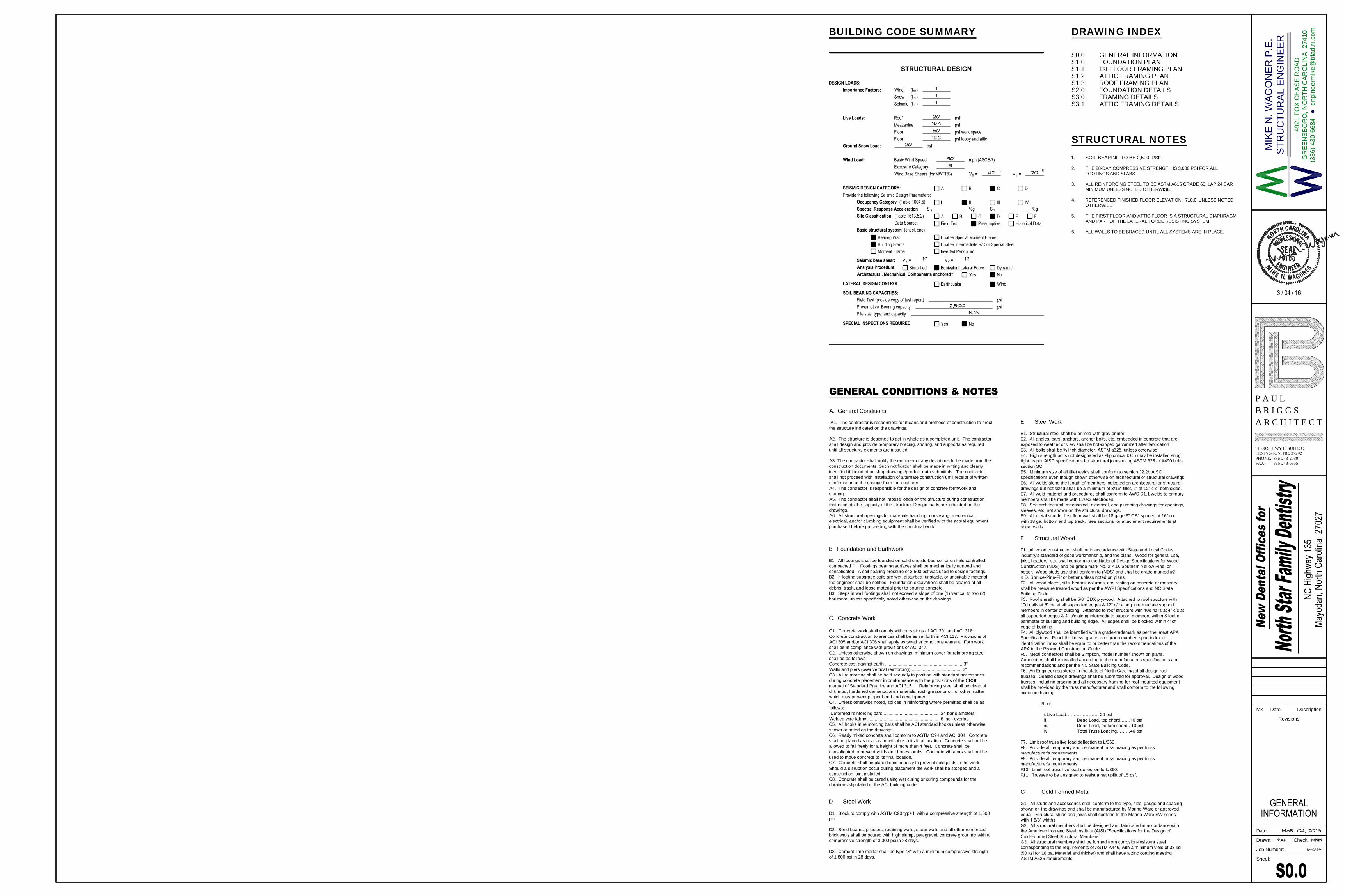
ROOF FRAMING PLAN1SCALE: 3/16"=1'-0"
2'-0"
(TYP.)
TRUSSES AT 24" O.C.
LOAD BEARING WALL
LOAD BEARING AND SHEAR WALL
RIDGE
2 x 8 AT 24" O.C.2 x 8 AT 24" O.C.
2
S3.1
1
S3.1
2
S3.1
TR
US
S S
EC
TIO
N S
HO
WIN
G V
AR
RY
IN
G T
RU
SS
L
EN
GT
HS
T
R
U
S
S
O
N
E
LOAD BEARING
AND SHEAR WALL
12" GLULAM BEAM
CAPC. = 300 PLF
TYP. AT (4) HIPS
1
S3.0
10
S.3.1
10
S3.0
2 x 8 RAFTERS AT 24" O.C.
2 x 4 BLOCKING AT ALL RIDGE AND VALLEY LINES
1
S3.0
4
S3.0
1
S3.0
4
S3.1
2 x 8 RAFTERS AT 24" O.C.
W1
2x2
2
W12x22
W1
2x2
2
W12x22
T
S
4
"
x
4
"
x
1
4
"
T
Y
P
.
T
S
4
"
x
4
"
x
14
"
T
Y
P
.
T
S
4
"
x
4
"
x
1
4
"
T
Y
P
.
T
S
4
"
x
4
"
x
1
4
"
T
Y
P
.
2 x 8 RAFTERS
2 x 8
RAFTERS
TRUSS 4
TRUSS 3
TRUSS 3
TRUSS 3
TRUSS 3
TRUSS 3
TRUSS 3
TRUSS 3
TRUSS 3
(
2
)
2
x
1
0
(
2
)
2
x
1
0
4'-6" 18'-8" 4'-6"
25
'-4
"
59
'-0
1
4" O
UT
T
O O
UT
M
ET
AL
S
TU
DS
104'-4
1
4" OUT TO OUT METAL STUDS
A
E
10
1
1
E
A
DD
C
C.1
C
B
A.9
B.6
13
'-1
0
3
8"
8'-6
1
2"
1'-0
3
4"
8'-3
5
8"
10
'-0
"1
7'-3
"
13
'-1
0
3
8"
8'-6
1
2"
1'-0
3
4"
7'-1
1"
15
'-2
"
10
32 4 5 7 8 8.2 96 6.7
6
B.8
B
2'-1
"
4'-5
1
2"
8.1
B.9
4.6 6.3
4'-5
1
2" 43'-6" 18'-8" 42'-8
1
8" 4'-5
1
2"
4'-5
1
2" 11'-4
5
8" 81'-7" 11'-4
5
8" 4'-5
1
2"
DOUBLE 2x10 RAFTERS
15
'-1
0
1
8"
36
'-3
"1
5'-1
0
1
8"
STICK FRAME
1) -
ROOF CONSTRUCTION
1
S3.0
81'-1"
1
S3.0
4
S3.0
10
S3.0
3'-9
1
4" 11'-1
1
2" 3'-9
1
4"
4
S3.1
5
S3.1
B.6
B.4
2'-1
"
7'-1
0
15
16"
B.8
4
5
8"
59
'-0
1
4" O
UT
T
O O
UT
M
ET
AL
S
TU
DS
104'-4
1
4" OUT TO OUT METAL STUDS
ROOFFRAMING PLAN
Date:
Sheet:
Revisions
Mk Date Description
MAR. 04, 2016
15-019
Drawn: Check:
Job Number:
3 / 04 / 16
4921 F
OX
C
HA
SE
R
OA
D
GR
EE
NS
BO
RO
, N
OR
TH
C
AR
OLIN
A 27410
(336) 430-6684 engineerm
ike@
triad.rr.com
MIK
E N
. W
AG
ON
ER
P
.E
.
ST
RU
CT
UR
AL E
NG
IN
EE
R
RAH MNW
NC H
ighwa
y 135
Mayo
dan,
North
Car
olina
270
27
P A U LB R I G G SA R C H I T E C T
11500 S. HWY 8, SUITE CLEXINGTON, NC, 27292PHONE: 336-248-2030FAX: 336-248-6355
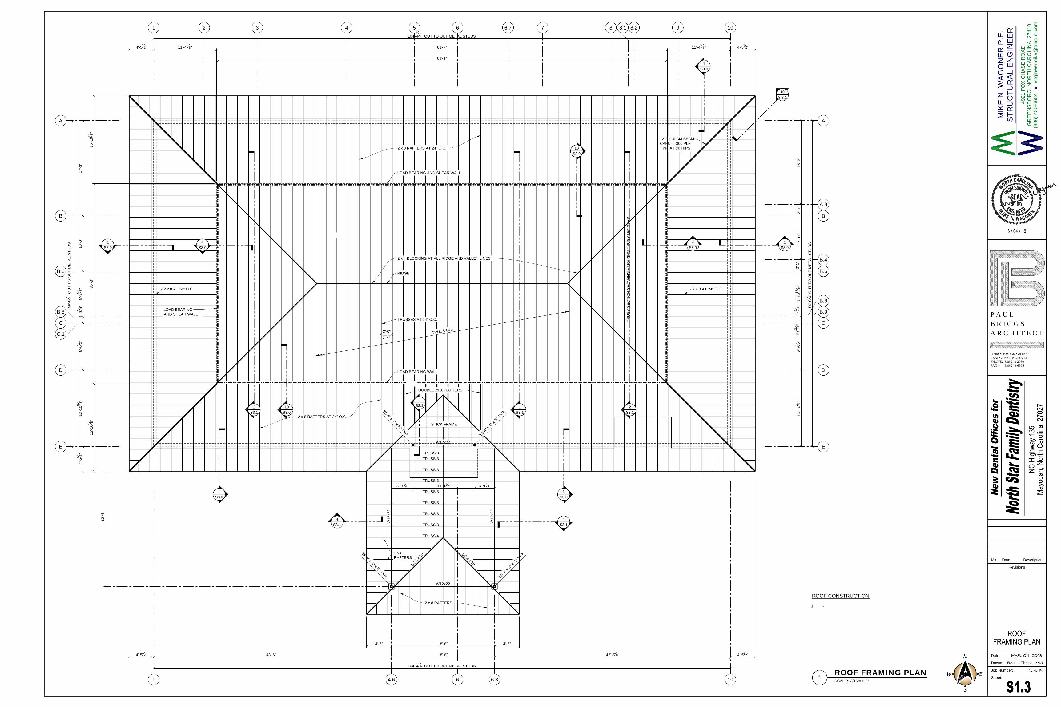
SECTION AT FOUNDATION WALL3SCALE: 3/4"=1'-0"
2'-6"
T/ FOOTING
EL. (SEE PLAN)
T/ BOND BEAM
EL. 708'-11 5/8"
3/4" TONGUE & GROOVE
PLYWOOD SUBFLOOR
5/8" UNDERLAYMENT
2x8 WOOD BLOCKING
BOND BEAM
#4 REBAR AT 32" O.C.
8" C.M.U. (6) COURSES
1'-0
"
CRAWL SPACE
EL. VARIES
T/ FLOOR
EL. 710'-0"
FINISH GRADE
4'-0
"
(2) #4 CONT.
w/ #4 TIES AT
48" O.C.
#4 AT 48" O.C.
GRADE
EL. 709'-0" ±
COMPACTED EARTH
10" RIM BOARDS
6" METAL STUDS
5/8" G.W.B.
9 1/2" TJI AT 12" O.C.
7
5
8"
SEE FOUNDATION
PLAN FOR
ELEVATION
SECTION "1"1SCALE: 3/4"=1'-0"
SECTION "2"2SCALE: 3/4"=1'-0"
2'-6"
BOND BEAM
#4 REBAR AT 32" O.C.
8" C.M.U.
T/ FLOOR
EL. 710'-0"
#4 AT 48" O.C.
(3) #4 CONT.
STONE FACING
(SEE ARCH.)
7
5
8"
16 GA. TRACK
3/4" TONGUE & GROOVE
PLYWOOD SUBFLOOR
5/8" UNDERLAYMENT
5/8" G.W.B.
9
1
2
" TJI (SEE PLAN
FOR SPACING
T/ FOOTING
EL. (SEE PLAN)
GRADE VARIES
w/ G
RA
DE
3/8" ANCHOR AT 24"
O.C.
2'-6"
T/ FOOTING
EL. 700'-11 5/8"
T/ BOND BEAM
EL. 708'-11 5/8"
2x8
BOND BEAM w/ (2)
#4 REBAR CONT.
#4 REBAR AT 32" O.C.
12" C.M.U. (11) COURSES
1'-0
"
FINISH FLR.
EL. 701'-5 5/8"
T/ FLOOR
EL. 710'-0"
8'-0
"
#4 AT 48" O.C.
COMPACTED
EARTH
(3) #4 CONT.
w/ #4 TIES AT
48" O.C.
3/4" TONGUE & GROOVE
PLYWOOD SUBFLOOR
5/8" UNDERLAYMENT
4" CONC. FLOOR SLAB w/
6-6 10/10 WELDED WIRE
MESH
MECHANICAL
ROOM
7'-7
1
2"
10
7
8"
VAPOR
BARRIER
9 1/2 TJI
AT 12" O.C.
(3) 2 x 10
T/ FLOOR
EL. 710'-0"
1
3
8"
1
3
8"
9
1
2"
8'-6
3
8"
1'-0
3
8"
#4 AT 32" O.C.
#4 AT 32" O.C.
1'-0" x 2'-6" CONC.
FOOTING w/ (3) #4 CONT.
1'-4
"
6"
7
5
8"
701.33' ± GRADE
AT DOOR
6'-8" ±
BLOCK COURSING
EL. 708'-11 5/8"
1'-0
3
8"
1'-0
"
W10 BEAM
6
5
8"
6
5
8"
5/8" G.W.B.
18 GA. 6" METAL STUDS AT
16" O.C. (TYPICAL)
6"
5
8"
6"
5
8"
18 GA. 6" METAL STUDS AT
16" O.C. (TYPICAL)
16 GA. TRACK
3/8" ANCHOR AT 24" O.C.
(TYPICAL)
SECTION 66SCALE: 3/4"=1'-0"
2'-6"
T/ FOOTING
EL. 700'-11 5/8"
2x8 WOOD BLOCKING
BOND BEAM
#4 REBAR AT 32" O.C.
8" C.M.U.
1'-0
"
FINISH FLR.
EL. 701'-5 5/8"
T/ FLOOR
EL. 710'-0"
8'-1
1
2"
#4 AT 48" O.C.
CRAWLSPACE
EL. 705.0 ±
COMPACTED
EARTH
(2) #4 CONT.
w/ #4 TIES AT
48" O.C.
7
5
8"
3/4" TONGUE & GROOVE
PLYWOOD SUBFLOOR
5/8" UNDERLAYMENT
4" CONC. FLOOR SLAB w/
6-6 10-10 WIRE MESH
MECHANICAL
ROOM
7'-7
1
2"
10
7
8"
FINISH GRADE
VAPOR
BARRIER
B/ TJI
EL. 709'-1 1/8"
10 TJI AT 12" O.C.
CONTINUOUS
T/ MASONRY
EL. 708'-11 5/8"
10 TJI AT 12" O.C.
CONTINUOUS
8'-6
3
8"
SECTION 44SCALE: 3/4"=1'-0"
2'-6"
T/ FOOTING
EL. 700'-11 5/8"
2x8 WOOD BLOCKING
BOND BEAM w/ (1) #4 CONT.
#4 REBAR AT 32" O.C.
8" C.M.U.
1'-0
"
FINISH FLR.
EL. 701'-5 5/8"
T/ FLOOR
EL. 710'-0"
13
C
OU
RS
ES
A
T 8
" =
8
'-8
1
4"
#4 AT 48" O.C.
CRAWLSPACE
EL. VARIES
COMPACTED
EARTH
(2) #4 CONT.
w/ #4 TIES AT
48" O.C.
3/4" TONGUE & GROOVE
PLYWOOD SUBFLOOR
5/8" UNDERLAYMENT
4" CONC. FLOOR SLAB w/
6-6 10-10 WIRE MESH
MECHANICAL
ROOM
7'-7
1
2" ±
10
7
8"
FINISH GRADE
VAPOR
BARRIER
B/ TJI
EL. 709'-1 1/8"
10 TJI AT 12" O.C.
10 TJI AT 12" O.C.
8'-6
3
8"
6"
T/ BOND BEAM
EL. 709'-7 5/8"
BLOCKING BETWEEN
JOISTS
STONE FACING
(SEE ARCH.)
6'-1
0"
STONE FACING
(SEE ARCH.)
9
1
2"
CRAWL SPACE ELEVATION
VARIES
T/ FLOOR
EL. 710'-0"
SECTION 55SCALE: 3/4"=1'-0"
1" PROTECTION
BOARD
WATERPROOF
MEMBRANE
2 x 6 WOOD NAILER
2 x 6 WOOD NAILER
2 x 6 WOOD NAILER
AT
L
IN
E E
VA
RIE
SA
T L
IN
E A
2'-6"
T/ FOOTING
EL. 706'-11 5/8"
1'-0
"
(2) #4 CONT.
w/ #4 TIES AT
48" O.C.
T/ BOND BEAM
EL. 708'-3 5/8"
(2) 3/4" ANCHOR BOLTS
GRADE
EL. 707'-0" ±
PLATE 1/2" x 10" x 10"
(SEE DETAIL 7)
T/ FLOOR
EL. 710'-0"
C
L
10 TJI10 TJI
T/ BOND BEAM
EL. 708'-11 5/8"
COPE
B/ BEAM
EL. 708'-1 5/8"
W10 x 17
B/ TJI
EL. 709'-1 1/8"
11'-1
1
2"
11'-9
1
2" OUT TO OUT OUTSIDE
STUD WALL
4" x 4" x 1/4" POST
1 1/2" NAILER
ON LINE 6 & 6.1
EL. 709'-7 5/8"
T/ BOND BEAM
ON LINE E
5/8" CDX PLYWOOD
(TYPICAL)
5/8" CDX PLYWOOD
(TYPICAL)
1" PROTECTION
BOARD
WATERPROOF
MEMBRANE
VA
RIE
S
5/8" CDX PLYWOOD
(TYPICAL)
7
5
8"
8
A2.0
BASE PLATE DETAIL7SCALE: 1 1/2"=1'-0"
8" WALL
C
L
4"x4"x1/4" POST
1/2" BASE PLATE
8" W
AL
L
MODIFY BOND BEAM TO
PROVIDE BASE PLATE
BEARING AT 708'-3 5/8"
4"
6"
11'-1
1
2"
11'-9
1
2"
10
"
10"
TYP. TJI CONNECTION TO BOTTOM PL.8SCALE: 1 1/2"=1'-0"
8d x 2 1/2"
EACH SIDE
1
1
2"
MIN.
FOUNDATIONDETAILS
Date:
Sheet:
Revisions
Mk Date Description
MAR. 04, 2016
15-019
Drawn: Check:
Job Number:
3 / 04 / 16
4921 F
OX
C
HA
SE
R
OA
D
GR
EE
NS
BO
RO
, N
OR
TH
C
AR
OLIN
A 27410
(336) 430-6684 engineerm
ike@
triad.rr.com
MIK
E N
. W
AG
ON
ER
P
.E
.
ST
RU
CT
UR
AL E
NG
IN
EE
R
RAH MNW
NC H
ighwa
y 135
Mayo
dan,
North
Car
olina
270
27
P A U LB R I G G SA R C H I T E C T
11500 S. HWY 8, SUITE CLEXINGTON, NC, 27292PHONE: 336-248-2030FAX: 336-248-6355

SECTION 33SCALE: 3/4"=1'-0"
2 x 6 NAILER. STAGGER 3/8"
DIA. NAILER BOLTS AT 12" O.C.
(TYPICAL)
SECTION 55SCALE: 3/4"=1'-0"
2 x 6
W10x12
2 x 10 BOCKING BETWEEN
JOISTS
6" METAL STUDS x 18 GA. AT
12" O.C. (LOCATE WALL PER
ARCHITECT'S DRAWINGS)
12 TJI (11
7
8
")
10
1
W10x22
(2) 11 7/8" RIM
BOARDS OR LSL
2 x 6 TOP PLATE
(FASTEN TO STUD)
OUTSIDE OF
6" METAL STUD
ATTIC FLOOR
3/4" TONGUE & GROOVE
PLYWOOD SUBFLOOR
5/8" UNDERLAYMENT
SECTION AT WIND FRAME LINE 1 & 1014SCALE: 3/4"=1'-0"
FIRST FLOOR
EL. 710'-0"
ATTIC FLOOR
EL. 722'-8"
A B
11
S3.0
W10x22
12
S3.0
TS
4
"x4
"x1
/4
"
TS
4
"x4
"x1
/4
"
T
S
4
"
x
4
"
x
1
/
4
"
1
5
k
SECTION 1111SCALE: 3/4"=1'-0"
SECTION 66SCALE: 3/4"=1'-0"
2
W10X17
12TJI 110 (11
7
8
")
2 x 6 BLOCKING
12TJI 360
3/4" TONGUE & GROOVE
PLYWOOD SUBFLOOR
5/8" UNDERLAYMENT
ATTIC FLOOR
SECTION 1010SCALE: 3/4"=1'-0"
12TJI 360 AT 12" O.C.
(2) 2 x 6
SHEAR WALL
TRUSS ONE AND
SPECIAL TRUSSES
AT 24" O.C.
12
5
2 x 8 AT 24" O.C.
17'-6
1
8"
5
12
EAVE DETAIL1SCALE: 3/4"=1'-0"
6" x 18 GA. METAL STUDS AT
16" O.C.
(2) 2 x 6 WOOD BLOCKING
5/8" CDX PLYWOOD
(SEE ARCH.)
EXTERIOR TRIM
(SEE ARCH)
2 x 4 WD. BLK'G.
AS REQ'D.
2 x 4
2 x 8
3/4" PLYWOOD
SHEATHING
ROOFING MATERIAL
(SEE ARCH.)
SIMPSON
H25A
G.W.B.
(2) 11 7/8" RIM BOARDS OR LSL
9
1'-0"
6" x 18 GA. METAL
STUDS AT 16" O.C.
4'-5
1
2"
4'-2
1
2" 3"
1'-2
3
4"
SECTION 1212SCALE: 3/4"=1'-0"
10
1
3"
TS 4 x 4 x 1/4" COLUMN
8" C.M.U.
BOND BEAM W/ (1) #4 CONT.
BASE PLATE 1/2" x 7" x 10"
T/ MASONRY
EL. 709'-7 5/8"
(2) 5/8" x 1'-4" ANCHORS
(SEE SECTION 5 TOP
WALL SECTION)
T/ FLOOR
EL. 710'-0"
(2) 2x8 PLATES
(B/ COL. BASE PLATE
& T/ BOND BEAM )
T/ FLOOR
EL. 722'-8"
10 TJI
3/4" TONGUE & GROOVE
PLYWOOD SUBFLOOR
5/8" UNDERLAYMENT
2
9
B
D
W10 FLOOR BEAM
TIE DOWN CONNECTION
AT 24" O.C.
12 TJI (11
7
8
")
6" x 18 GA.
METAL STUDS
LOAD
BEARING
SHEAR WALL
ATTIC FLR.
EL. 722'-8"
3/4" TONGUE & GROOVE
PLYWOOD SUBFLOOR
5/8" UNDERLAYMENT
ATTIC FLOOR
SEE PLAN FOR SPACING AT
DUCT PENETRATIONS
(2) 11 7/8" RIM BOARDS
OR LSL
ATTIC FLR.
EL. 722'-8"
T/ BOND BM.
EL. 709'-7 5/8"
T/ W10x22
EL. 721'-5 1/4"
11
'-5
1
4"
A.9
15'-2"
B
A.9
AT LINE
AT LINE
36'-3" OUT TO OUT LOAD BEARING WALLS
12 TJI
(2) 11 7/8" RIM
BOARDS OR LSL
1'-0"1'-0"1'-0"1'-0"
6" METAL STUDS x 18 GA. AT
12" O.C. (LOCATE WALL PER
ARCHITECT'S DRAWINGS)
SECTION 88SCALE: 3/4"=1'-0"
3/4" TONGUE & GROOVE
PLYWOOD SUBFLOOR
5/8" UNDERLAYMENT
ATTIC FLOOR
3/4" TONGUE & GROOVE
PLYWOOD SUBFLOOR
5/8" UNDERLAYMENT
ATTIC FLOOR
8'-0
"
ATTIC FLR.
EL. 722'-8"
T/ STUD
EL. 730'-8"
SECTION 44SCALE: 3/4"=1'-0"
12TJI 360 AT 12" O.C.
1/2" FILLER
SHEAR WALL
6" x 18 GA. METAL
STUDS AT 16" O.C.
(2) 2 x 6
1/2" FILLER (TYP.)
12
5
2 x 8 AT 16" O.C.
HGA10
AT 32" O.C.
LSU8 OR
LRU28Z
6" x 18 GA. METAL
STUDS AT 16" O.C.
3/4" TONGUE & GROOVE
PLYWOOD SUBFLOOR
5/8" UNDERLAYMENT
ATTIC FLOOR
8'-0
"
ATTIC FLR.
EL. 722'-8"
T/ STUD
EL. 730'-8"
(2) TJI 110s
TRUSS
SECTION 99SCALE: 3/4"=1'-0"
12TJI
(2) 2 x 6
6" x 18 GA. METAL
STUDS AT 16" O.C.
3/4" TONGUE & GROOVE
PLYWOOD SUBFLOOR
5/8" UNDERLAYMENT
ATTIC FLOOR
6" x 12 GA. METAL
STUDS AT 16" O.C.
1'-0" ±
ATTIC FLR.
EL. 722'-8"
1
10
SECTION 77SCALE: 3/4"=1'-0"
W10x15
3/4" TONGUE & GROOVE
PLYWOOD SUBFLOOR
5/8" UNDERLAYMENT
ATTIC FLOOR
12 TJI
SECTION AT LINE E2SCALE: 3/4"=1'-0"
W10x15
C
L POST
ATTIC FLR.
EL. 722'-8"
11'-9
1
2"
4"11'-1
1
2"
12 TJI 560
2x4 NAILER
(BEYOND)
3/8" PLATE
TS 4"x4"x1/4" POST
6" x 12 GA. METAL
STUDS AT 16" O.C.
3/4" T & G
PLY. SUBFLR.
5/8" UNDERLAYMENT
DETAIL 1313SCALE: 3/4"=1'-0"
W10x15
ATTIC FLR.
EL. 722'-8"
TJI 560
2x4
NAILER
3/8" PLATE
TS 4"x4"x1/4" POST
3/4" T & G
PLY. SUBFLR.
1'-2
3
4"
C
L POST
TS 4"x4"x1/4"
BRACE
CHIP AND CUT NEAR SIDE
FLANGE OF W10x22
C
L
3/16 2 @ 12"
3/16 3"
13
A3.0
13
A3.0 SIM.
C
L
1'-0" O.C.
TYP.
5/8" CDX PLYWOOD
E
T/ FLOOR
EL. 722'-8"
T/ FLOOR
EL. 722'-8"
(2) 2 x 6 WOOD BLOCKING
5/8" EXT. SHEATHING
(SEE ARCH.)
(2) 11 7/8" RIM BOARDS
OR LSL
T/ FLOOR
EL. 710'-0"
6" x 12 GA. METAL
STUDS AT 16" O.C.
ATTIC FLOOR
(BEYOND)
(2) 2 x 6
2 x 12
6" x 18 GA. METAL
STUDS AT 16" O.C.
5/8" G.W.B.
5/8" G.W.B. (EACH SIDE)
5/8" CDX PLYWOOD
(1 SIDE ONLY)
5/8" CDX PLYWOOD
5/8" CDX PLYWOOD
11 7/8" RIM BD.
OR LSL
5/8" CDX
PLYWOOD
11
"
LSU 28 OR
LRU28Z
ELEV.
731'-8 1/2"
(2) 2 x 6
(2) TBE 6
SIMPSON L 70
2 x 10
5/8" CDX
PLYWOOD
(2) 2 x 6
1/2" FILLER
3/8" BOLT
AT 24" O.C.
S/H2.5A
AT 16" O.C.
3/8" BOLT AT
24" O.C. (TYP.)
(2) 2 x 6
1/2" FILLER
S/H2.5A
AT 16" O.C.
(2) 2 x 6
S/H2.5A
AT 16" O.C.
ELEV. 731'-8
1
2
"
2 x 4 STRUT
AT 32" O.C.
ST6224
PROVIDE 2
1
16
" WIDE x 16 GA. STRAP
ANCHOR x 23
3
16
" (ST6224) AT 32" O.C.
SIMPSON CONNECTION
CLIP
FRAMINGDETAILS
Date:
Sheet:
Revisions
Mk Date Description
MAR. 04, 2016
15-019
Drawn: Check:
Job Number:
3 / 04 / 16
4921 F
OX
C
HA
SE
R
OA
D
GR
EE
NS
BO
RO
, N
OR
TH
C
AR
OLIN
A 27410
(336) 430-6684 engineerm
ike@
triad.rr.com
MIK
E N
. W
AG
ON
ER
P
.E
.
ST
RU
CT
UR
AL E
NG
IN
EE
R
RAH MNW
NC H
ighwa
y 135
Mayo
dan,
North
Car
olina
270
27
P A U LB R I G G SA R C H I T E C T
11500 S. HWY 8, SUITE CLEXINGTON, NC, 27292PHONE: 336-248-2030FAX: 336-248-6355
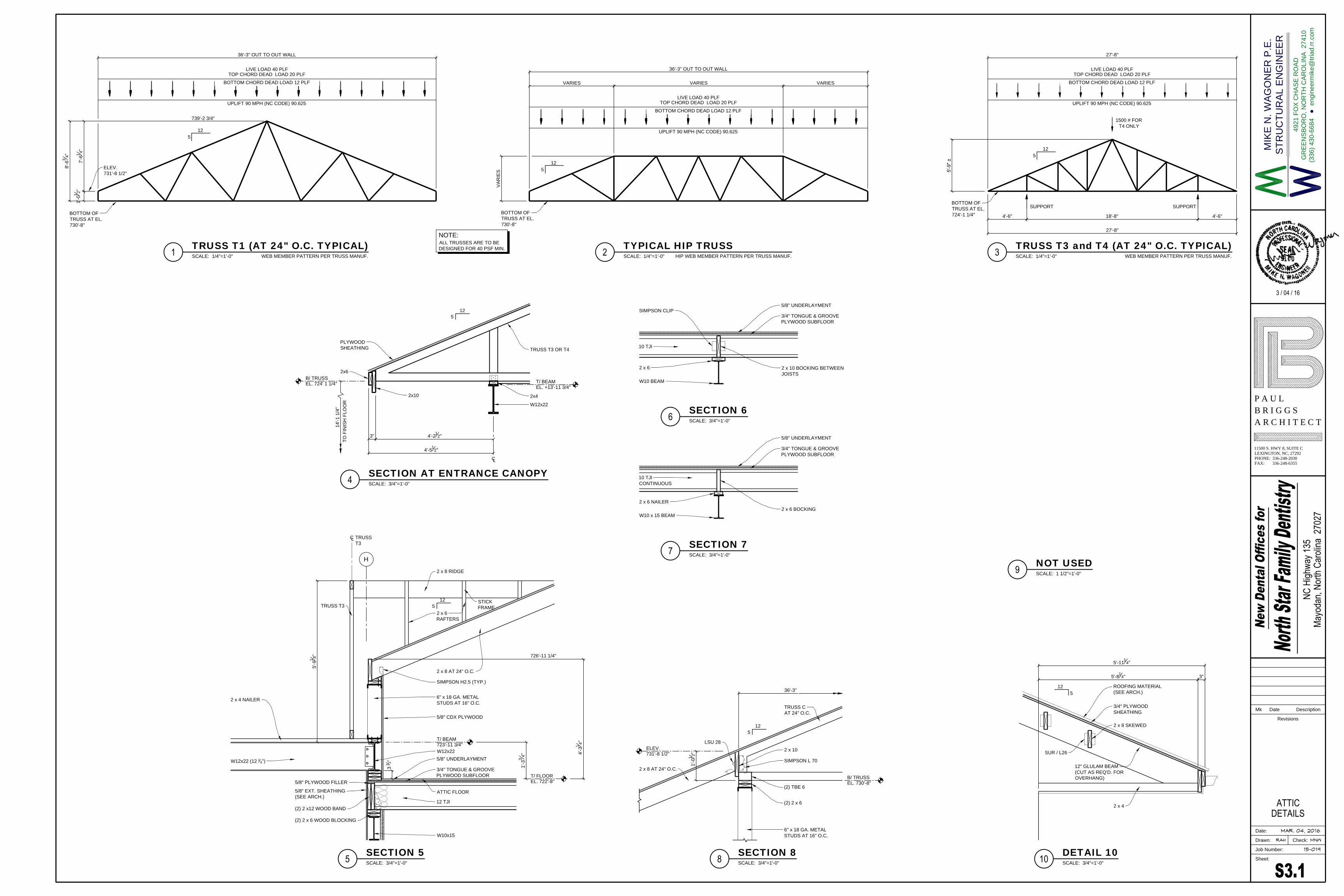
TRUSS T1 (AT 24" O.C. TYPICAL)1SCALE: 1/4"=1'-0"
7'-6
1
4"
5
12
TYPICAL HIP TRUSS 2SCALE: 1/4"=1'-0"WEB MEMBER PATTERN PER TRUSS MANUF.
36'-3" OUT TO OUT WALL
BOTTOM CHORD DEAD LOAD 12 PLF
TOP CHORD DEAD LOAD 20 PLF
UPLIFT 90 MPH (NC CODE) 90.625
VA
RIE
S
36'-3" OUT TO OUT WALL
VARIES VARIES VARIES
HIP WEB MEMBER PATTERN PER TRUSS MANUF.
5
12
LIVE LOAD 40 PLF
BOTTOM CHORD DEAD LOAD 12 PLF
TOP CHORD DEAD LOAD 20 PLF
UPLIFT 90 MPH (NC CODE) 90.625
LIVE LOAD 40 PLF
TRUSS T3 and T4 (AT 24" O.C. TYPICAL)3SCALE: 1/4"=1'-0"
5'-9" ±
5
12
WEB MEMBER PATTERN PER TRUSS MANUF.
BOTTOM CHORD DEAD LOAD 12 PLF
TOP CHORD DEAD LOAD 20 PLF
UPLIFT 90 MPH (NC CODE) 90.625
LIVE LOAD 40 PLF
27'-8"
27'-8"
4'-6" 18'-8" 4'-6"
1500 # FOR
T4 ONLY
ALL TRUSSES ARE TO BE
DESIGNED FOR 40 PSF MIN.
NOTE:
SUPPORTSUPPORT
BOTTOM OF
TRUSS AT EL.
724'-1 1/4"
BOTTOM OF
TRUSS AT EL.
730'-8"
BOTTOM OF
TRUSS AT EL.
730'-8"
1'-0
1
2"
ELEV.
731'-8 1/2"
739'-2 3/4"
8'-6
3
4"
SECTION AT ENTRANCE CANOPY4SCALE: 3/4"=1'-0"
5
12
2x6
2x10
4'-2
1
2"
4'-5
1
2"
3"
C
L
2x4
W12x22
TRUSS T3 OR T4
PLYWOOD
SHEATHING
12
5
SECTION 55SCALE: 3/4"=1'-0"
2 x 8 AT 24" O.C.
H
W10x15
3/4" TONGUE & GROOVE
PLYWOOD SUBFLOOR
5/8" UNDERLAYMENT
ATTIC FLOOR
12 TJI
T/ FLOOR
EL. 722'-8"
(2) 2 x 6 WOOD BLOCKING
5/8" EXT. SHEATHING
(SEE ARCH.)
5/8" PLYWOOD FILLER
(2) 2 x12 WOOD BAND
W12x22
W12x22 (12
1
4
")
C
L
TRUSS
T3
4'-3
1
4"
6" x 18 GA. METAL
STUDS AT 16" O.C.
726'-11 1/4"
5'-9
1
8"
T/ BEAM
EL. +13'-11 3/4"
14
'-1
1
/4
"
TO
F
IN
IS
H F
LO
OR
T/ BEAM
723'-11 3/4"
B/ TRUSS
EL. 724' 1 1/4"
TRUSS T3
2 x 4 NAILER
SECTION 66SCALE: 3/4"=1'-0"
2 x 6
W10 BEAM
2 x 10 BOCKING BETWEEN
JOISTS
10 TJI
3/4" TONGUE & GROOVE
PLYWOOD SUBFLOOR
5/8" UNDERLAYMENT
SIMPSON CLIP
SECTION 77SCALE: 3/4"=1'-0"
2 x 6 NAILER
W10 x 15 BEAM
2 x 6 BOCKING
10 TJI
CONTINUOUS
3/4" TONGUE & GROOVE
PLYWOOD SUBFLOOR
5/8" UNDERLAYMENT
SECTION 88SCALE: 3/4"=1'-0"
(2) 2 x 6
TRUSS C
AT 24" O.C.
12
5
2 x 8 AT 24" O.C.
SIMPSON L 70
B/ TRUSS
EL. 730'-8"
6" x 18 GA. METAL
STUDS AT 16" O.C.
2 x 10
1'-0
1
2"
LSU 28
(2) TBE 6
ELEV.
731'-8 1/2"
36'-3"
5
12
DETAIL 1010SCALE: 3/4"=1'-0"
2 x 4
2 x 8 SKEWED
3/4" PLYWOOD
SHEATHING
ROOFING MATERIAL
(SEE ARCH.)
5'-11
1
4"
5'-8
1
4" 3"
12" GLULAM BEAM
(CUT AS REQ'D. FOR
OVERHANG)
SUR / L26
1'-3
3
4"
3
1
2"
5/8" CDX PLYWOOD
SIMPSON H2.5 (TYP.)
2 x 6
RAFTERS
2 x 8 RIDGE
STICK
FRAME
NOT USED9SCALE: 1 1/2"=1'-0"
ATTICDETAILS
Date:
Sheet:
Revisions
Mk Date Description
MAR. 04, 2016
15-019
Drawn: Check:
Job Number:
3 / 04 / 16
4921 F
OX
C
HA
SE
R
OA
D
GR
EE
NS
BO
RO
, N
OR
TH
C
AR
OLIN
A 27410
(336) 430-6684 engineerm
ike@
triad.rr.com
MIK
E N
. W
AG
ON
ER
P
.E
.
ST
RU
CT
UR
AL E
NG
IN
EE
R
RAH MNW
NC H
ighwa
y 135
Mayo
dan,
North
Car
olina
270
27
P A U LB R I G G SA R C H I T E C T
11500 S. HWY 8, SUITE CLEXINGTON, NC, 27292PHONE: 336-248-2030FAX: 336-248-6355