Embed Size (px)
Citation preview
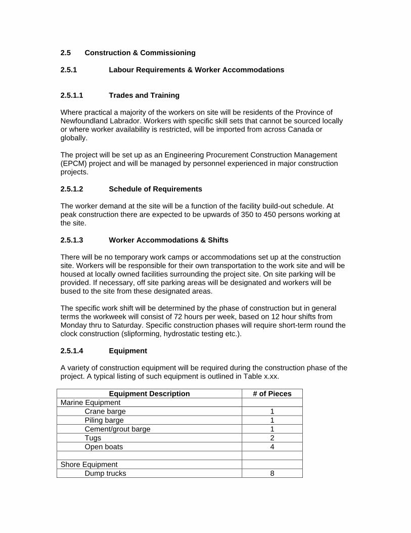
2.5 Construction & Commissioning 2.5.1 Labour Requirements & Worker Accommodations 2.5.1.1 Trades and Training Where practical a majority of the workers on site will be residents of the Province of Newfoundland Labrador. Workers with specific skill sets that cannot be sourced locally or where worker availability is restricted, will be imported from across Canada or globally. The project will be set up as an Engineering Procurement Construction Management (EPCM) project and will be managed by personnel experienced in major construction projects. 2.5.1.2 Schedule of Requirements The worker demand at the site will be a function of the facility build-out schedule. At peak construction there are expected to be upwards of 350 to 450 persons working at the site. 2.5.1.3 Worker Accommodations & Shifts There will be no temporary work camps or accommodations set up at the construction site. Workers will be responsible for their own transportation to the work site and will be housed at locally owned facilities surrounding the project site. On site parking will be provided. If necessary, off site parking areas will be designated and workers will be bused to the site from these designated areas. The specific work shift will be determined by the phase of construction but in general terms the workweek will consist of 72 hours per week, based on 12 hour shifts from Monday thru to Saturday. Specific construction phases will require short-term round the clock construction (slipforming, hydrostatic testing etc.). 2.5.1.4 Equipment A variety of construction equipment will be required during the construction phase of the project. A typical listing of such equipment is outlined in Table x.xx.
Equipment Description # of Pieces Marine Equipment
Crane barge 1 Piling barge 1 Cement/grout barge 1 Tugs 2 Open boats 4
Shore Equipment
Dump trucks 8
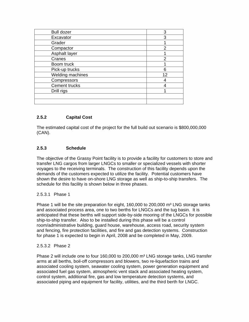
Bull dozer 3 Excavator 3 Grader 1 Compactor 2 Asphalt layer 1 Cranes 2 Boom truck 1 Pick-up trucks 6 Welding machines 12 Compressors 4 Cement trucks 4 Drill rigs 1
2.5.2 Capital Cost The estimated capital cost of the project for the full build out scenario is $800,000,000 (CAN). 2.5.3 Schedule The objective of the Grassy Point facility is to provide a facility for customers to store and transfer LNG cargos from larger LNGCs to smaller or specialized vessels with shorter voyages to the receiving terminals. The construction of this facility depends upon the demands of the customers expected to utilize the facility. Potential customers have shown the desire to have on-shore LNG storage as well as ship-to-ship transfers. The schedule for this facility is shown below in three phases. 2.5.3.1 Phase 1 Phase 1 will be the site preparation for eight, 160,000 to 200,000 m³ LNG storage tanks and associated process area, one to two berths for LNGCs and the tug basin. It is anticipated that these berths will support side-by-side mooring of the LNGCs for possible ship-to-ship transfer. Also to be installed during this phase will be a control room/administrative building, guard house, warehouse, access road, security system and fencing, fire protection facilities, and fire and gas detection systems. Construction for phase 1 is expected to begin in April, 2008 and be completed in May, 2009. 2.5.3.2 Phase 2 Phase 2 will include one to four 160,000 to 200,000 m³ LNG storage tanks, LNG transfer arms at all berths, boil-off compressors and blowers, two re-liquefaction trains and associated cooling system, seawater cooling system, power generation equipment and associated fuel gas system, atmospheric vent stack and associated heating system, control system, additional fire, gas and low temperature detection systems, and associated piping and equipment for facility, utilities, and the third berth for LNGC.
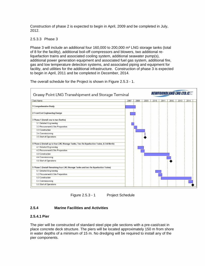
Construction of phase 2 is expected to begin in April, 2009 and be completed in July, 2012. 2.5.3.3 Phase 3 Phase 3 will include an additional four 160,000 to 200,000 m³ LNG storage tanks (total of 8 for the facility), additional boil-off compressors and blowers, two additional re-liquefaction trains and associated cooling system, additional seawater pump(s), additional power generation equipment and associated fuel gas system, additional fire, gas and low temperature detection systems, and associated piping and equipment for facility, and utilities for the additional infrastructure. Construction of phase 3 is expected to begin in April, 2011 and be completed in December, 2014. The overall schedule for the Project is shown in Figure 2.5.3 - 1.
Figure 2.5.3 - 1 Project Schedule
2.5.4 Marine Facilities and Activities 2.5.4.1 Pier The pier will be constructed of standard steel pipe pile sections with a pre-cast/cast in place concrete deck structure. The piers will be located approximately 150 m from shore in water depths of a minimum of 15 m. No dredging will be required to install any of the pier components.
The tug basin will be constructed of rock fill and concrete caissons. Dredging and possibly some rock blasting will be required to construct the tug basin. The final determination of dredging quantities and blasting will be based on the off shore bathymetry and geotechnical surveys. Pier Installation The pier installation will involved the following tasks:
Delivery of materials Pile installation Superstructure installation Mechanical/electrical outfitting
Delivery of Materials The first phase of the project will see the construction of the tug basin. This operation will involve constructing an access causeway/breakwater and a berth. The causeway/breakwater will be constructed from rock material excavated from the site. If appropriate rock size and quality cannot be sourced from the site it will be imported from nearby quarries. The concrete caissons used for the berth will be slip formed on site, launched and placed at the specified locations. Once complete the tug basin can be used as a construction dock for the import of construction materials. Material not being received over the construction dock will be brought to site via the existing highway system. Pile Installation The installation of the piles will involve several pieces of marine equipment including a crane barge, piling barge and concrete barge. The piles will be fabricated on site and transported to the piling barge where they will be installed. Each individual pile will be place in a pile driving template and driven to refusal into the underlying bedrock. Tension piles will have anchors installed in the annulus and will be grouted to achieve a bond between the anchor and pile. The anchors will be installed in pre-drilled holes in the bedrock and grouted inplace. After all the piles for each individual structure are installed they will be cut off at the specified elevation. Superstructure Installation After the pile installation is complete the concrete deck structure will be installed. Typical installation procedures include placing a pre-cast base over the previously installed piles. This base serves as both a structure part of the overall deck structure and a form for the remainder of the deck construction. A concrete form is placed around the perimeter of the cast in place deck and is filled with concrete to the specified thickness. The upper portion of the piles that are embedded into the pile cap are tied to the pile cap structure with steel reinforcing bars.
Miscellaneous structures such as roadway girders and access trestles/walkways are then installed between the main marine structures. Mechanical / Electrical Outfitting Once the superstructure is complete all mechanical and electrical equipment can be installed on the marine structures. 2.5.4.2 Marine Traffic The vessel traffic lane is currently used by both Newfoundland Transshipment Ltd and the Refinery at Come-by-Chance. In comparison the vessel traffic generated during construction will be minimal. Many of the smaller components and equipment will be delivered to site via the roadway network. Larger items associated with the handling of LNG product can be delivered by barge. Construction material such as piles and steel plate for tanks can also be delivered by barge. The selected mode of delivery will be determined by the contractor based his delivery schedule, cost and fabrication location. 2.5.4.3 Salt Water Intake and Outfall Seawater intakes are required both for routine operations in providing cooling water for power generation and for liquefaction process and also for emergency fire suppression systems. For seawater supply for operational purposes, an intake consisting of two pipes will be installed in the area south of the tug basin, extending into water depths approximately –15.0 m to –18.0 m below LNT. These pipes will be complete with intake screens to inhibit the passage of marine species and to minimize the influent velocity of the seawater to reduce entrainment. The pipes will be installed by first fusing the entire length at a convenient on-shore location and then they will be floated into position and weighted using concrete anchor blocks. Once the blocks have been added, air will be evacuated from the pipes and they will be allowed to sink into the design position. This process is aided by an underwater diving team to make sure that it is anchored in the correct position and that there are no areas where the pipe is subject to abrasion by the substrate or an irregular sub-grade, which could result in deteriorated performance. Should sounding investigations during the design process indicate that there are depressed areas of the seabed in the path of the intake, a pad will be designed for the placement of the pipe such that it eliminates any sags. This pad will consist of washed granular material and will be of a narrow width sized only to accommodate the pipes and the anchoring system. In lieu of a granular pad, concrete pedestals may be used to elevate the intake. At the end of the intake, either one large or a series of smaller wedge-wire screens will be installed to minimize the influent velocity. These screens will be installed on concrete support structures and they will project up into the water column to reduce the potential for drawing sediment into the intake pipes. For fire protection, a separate intake will be located on the jetty at the site of the fire pumps. This intake will provide a direct seawater supply to the fire pumps for fire protection purposes at the jetty and will also be fed into a dedicated firewater supply line throughout the project site. The intake will be designed to accommodate the rapid, high
flows required by these pumps on an on-demand basis. As the firewater system will be a dry system, the intake will only be used in the event that the system is either being tested or used for an emergency. Screens will be included on the intake to prevent the entrainment of marine species in the intake location. The outfall for wastewater discharge will be constructed in a similar manner as the operational intake pipe system. The pipe will be fused and floated into position, then weighted with concrete anchoring blocks and sank into the permanent location. The discharge for the outfall will consist of a series of check valve diffusers, which will be installed on the perimeter of the outfall pipe. These diffusers will be installed a minimum of 15.0 below LNT and will project the wastewater into the surrounding ocean to diffuse the heat that has been collected from cooling operations. The number and spacing for the diffusers will be designed to maximize the dispersion of the parameters of concern into the water column as quickly as possible. The diffusers attach directly to the pipe prior to deployment and have no moving mechanical parts, so they have few maintenance requirements during operations. The section of the pipe containing the diffusers will be levelled as required either using a pad of washed granular material or concrete pedestals depending upon the characteristics of the ocean floor in that area. The outfall will be designed to accommodate the wastewater discharge from the site as well as the anticipated outflow of firewater under emergency conditions. 2.5.5 Land Facilities and Activities 2.5.5.1 Site Preparation and Construction The project site is currently an undeveloped, greenfield site that consists of naturally occurring terrain that must be prepared for construction of the project components. Conventional construction methods and practices will be used throughout for site preparation and construction. A detailed construction methodology will be developed specific to the activities to be undertaken to ensure that they are in accordance with good construction and environmental practices. The site preparation activities for this project include:
Site clearing and grubbing of organic matter; Installation of temporary facilities including office and worker facilities; Construction of access road to site; Excavation and infilling (cut/fill) of site to develop a well graded surface for the
project elements; Preparation of marshalling yard/laydown area; Construction of site access roads throughout the project area; Construction of marine facilities (jetties and tug basin); Construction of stormwater management system; Construction of wastewater collection systems; Construction of wastewater outfall; Construction of seawater intake; Construction of freshwater system to connect to adjacent municipal system; Construction of water distribution systems (freshwater and seawater); Construction of buildings and process facilities; Construction of containment facilities;
Installation of Tanks; Construction of electrical system; Paving of access roads; Construction of access control gates and perimeter fencing; and Landscaping.
Environmental protection practices will be used throughout all phases of construction to minimize and mitigate any impact on the environment. The cut and fill activities for site leveling will involve the application of standard earthmoving procedures in accordance with the EPP to be developed for construction. These include drilling and blasting, mechanical busting and mechanical excavation. Rock material will be removed by blasting and mechanical impact to free it for excavation. Till and USM will be excavated using conventional mechanical means including excavators, loaders and dozers. Blasting will be undertaken only by contractors licensed to do so in the province. Those contractors will be responsible for maintaining permits in good standing with all regulatory agencies for the duration of construction. Explosives and auxiliary materials will be stored by each contractor as stipulated in relevant legislation and in compliance with their operations permit. Blasting will be undertaken in such a manner as to make secure any elements and features designated to remain. Overblasting will not be permitted. In order to minimize the seismic impact, blasting patterns and procedures will be used to reduce the shock wave and noise. Blasting activities will be co-ordinated and scheduled to minimize the number of blasts required. Time-delay blasting may be used as necessary to control the debris scatter. Prior to any blast, the site will be surveyed to identify the presence of any sensitive animals. Presence of such animals could result in delay or cancellation of the blast until such time that the sensitive animals are no longer present. To minimize slumping of excavated surfaces during construction, adequate slopes will be used based upon the recommendation of soil specialists. Slopes will be routinely inspected for erosion. Any slopes subject to erosion will be corrected to prevent soils and other excavated material from getting carried into surrounding water bodies. Slopes for permanent finished-grade surfaces will be in accordance with the recommendations of geotechnical specialists and will be surface-finished accordingly to provide long-term stability. Dewatering will be undertaken with the objective of preventing drainage-related issues in the area surrounding the site. Protective measures such as installation of silt control screening will be used to prevent silt from precipitation runoff from progressing to the surrounding area. Velocity controls such as check dams will be used to assist in the removal of sediment that may be in that drainage water. Pumps may be used to assist with dewatering and will be used in such a manner as to prevent the passage of silted water into the surrounding area. Where pumps are used, backup capacity will be available in the event of a failure to provide secure control of the water flow. Surface water will be inhibited from entering the work site by using perimeter ditching to redirect the flow into one or more settling ponds that will be constructed to remove silt and turbidity prior to discharge back into the surrounding environment. The water will be
evaluated for compliance with the Provincial Environmental Control Water and Sewage Regulations prior to discharge. Dust generated during construction will be controlled using one or more conventional measures as applicable to the particular project component. These include: water spraying, wind breaks, spray-on adhesives and vegetative coverings. Chemical-based solutions will not be used or applied near water bodies. To protect watercourses around the project site, concrete will be prohibited from contact with any water body until it has adequately cured. No tools or equipment used in the production or placement of concrete will be washed in or adjacent to any water body. Formwork and procedures for concrete production and placement will be such that they will prevent spillage into any water body. Watercourse crossing will be constructed in accordance with permit requirements as stipulated by all regulatory agencies. Fish bearing streams will be crossed in accordance with DFO guidelines and standards. During the construction period, all activities will comply with the Construction Environmental Protection Plan (EPP). All required permits from regulatory agencies will be obtained prior to the start of any construction. Emergency response to oil or chemical spill procedures and clean up will be in accordance with Emergency Response Plan (ERP) approved by DOEC. 2.5.5.3 LNG Storage Tanks 2.5.5.3.3 LNG Tank Hydrostatic Testing All testing will be conducted following the guidelines detailed in the API 620 Appendix Q unless otherwise noted. Hydrostatic testing will be conducted using the seawater to simulate forces applied by the design load of LNG per API 620 Appendix Q.8. The fill level will be less than that for LNG due to the increased density of the seawater but the hydrostatic head will be equivalent. The inner tank will have a nominal design capacity ranging from 160 000 m³ to 200 000 m³. Based on API 620 appendix Q.3, the assumed minimum density for methane is 29.3 lb/ft³ (469.3 kg/m³). The seawater is assumed to have a density of 64.0 lb/ft³ (1 025.0 kg/m³). Using these numbers and an increase of 25% per API 620 Appendix Q.8.1, yields a required volume of seawater ranging from approximately 92 000 m³ to 114 500 m³ for one (1) tank or 736 000 m³ to 916 000 m³ for eight (8) tanks. Readily available untreated seawater will be used for the hydrostatic test. It will be pumped into the tank per API 620 Section 5.18, at a rate not to exceed 0.914 m of depth per hour. If necessary, sediment suspended in the water will be filtered out at the intake. The salinity of the water will be checked to determine a maximum allowable residence time in the tank to limit corrosion (Note: Salinity is lowest during March averaging 30.39 psu (30 390 ppm) and increases with depth per salinity statistics for Northern Placentia Bay, Bedford Institute of Oceanography 2006). No harmful levels of regulated substances are expected to be present. Elevated levels of iron may be found in the discharged water due to oxidation in the tank. To insure compliance with Section 36 of
the Fisheries Act which prohibits the deposit of a deleterious substance in water frequented by fish, the effluent will be tested prior to discharge, and treated if necessary. Before hydrostatic testing begins:
The inner tank will be thoroughly checked for tightness and structural integrity. All required permits will be obtained. Per API 620 Appendix Q.8, test preliminaries shall be completed. All equipment for measuring and recording during the hydrostatic test will be
installed. Hydrostatic Testing:
Will be performed before the annular insulation and suspended deck are installed.
The inner tank will be filled with water to the predetermined test level at a predetermined rate of fill.
Measurements will be taken and inspections made per API 620 Appendix Q.8. Pneumatic Testing:
Per API 620 Appendix Q.8.5, air pressure will be applied to the enclosed space above the water.
Pressure and vacuum relief valves will be tested at design levels. Measurements will be taken and inspections made.
9% Nickel steel tanks have been successfully tested using seawater. API 620 Appendix Q guidelines relating to hydrostatic testing of LNG tanks will be followed including: The sea water will be tested for the presence of microbiologically influenced
corrosion causing bacteria, hardness, and pH prior to and during the test. The sea water source will be evaluated for suspended sediment as described above. The maximum length of time the 9% Nickel steel will be exposed to sea water will be
determined, i.e., the seawater will be tested using corrosion coupons of the same alloy as the tank for a time period of not less than two weeks. A laboratory report will be issued prior to hydrostatic testing.
Exposure time will be minimized to limit corrosion of the 9% Nickel steel. If exposure time is expected to be greater than what is considered safe, the unprotected steel may be treated to inhibit corrosion before testing begins.
Fresh water will be made available for testing the process piping network and for a wash down of the inner surfaces of the tank as the seawater is drained out. See section 2.5.5.4.6 Piping Hydrostatic Testing.
Upon completion of the hydrostatic test, the water will be drained from the tank as quickly as is practical. Any trash or debris that settled out will also be removed. A sufficient quantity of fresh water will be provided to wash down the tank interior. The volume of water required is estimated to range from 1 025 m³ to 1 225 m³ for one (1) tank or 8 200 m³ to 9 800 m³ for eight (8) tanks. All freestanding water pools will be removed and the tank will then be allowed to air dry. As per API 620 Appendix C, foundation settlement readings will be taken prior to the start of the hydrostatic test and at regular time intervals during the entire filling, full liquid
height and then draining process. Settlement of the outer perimeter of the foundation will be measured at equidistant reference points around its circumference. Upon satisfactory completion of the tests, final inspections and a nitrogen purge, the tank will be considered satisfactory for its designed purpose prior to cooldown. 2.5.5.3.4 Borrow Pits and Quarries The large footprint of the project site lends itself to providing borrow materials required for use in construction through cut and fill operations. Site grading will be designed to maximize the balancing of cut and fill operations and to provide excavated rock material which can be crushed to supply concrete aggregates and other granular material for construction use. Any deposits of clean, well-graded materials encountered during excavation operations will be stockpiled for use on project components. Any supplemental granular material for road construction, concrete production or engineered fill will be obtained from existing quarries in the project area. No quarries or borrow pits are planned for this site. 2.5.5.3.5 Concrete On site concrete requirements will be met from two sources. During initial site development, the smaller concrete quantities will be sourced from local concrete providers. For construction of the piers, tug basin, LNG tanks and the various site foundations, an on site concrete batch plant will be required. For single containment storage tanks concrete volumes of approximately 5000 m3 to 6000 m3 per tank will be required. Each pier will require approximately 2200 m3 and the tug basin approximately 2600 m3. The batch plant will be located on site to avoid interference with site constructs and allow sufficient space for the stockpiling of aggregates. Cleaning of trucks and equipment will be performed in a designated area away from watercourses. Standard construction practices (WHMIS) regarding the storage and handling of cement and concrete additives will be implemented at the site. The handling and production of concrete will be performed in a specific manner to reduce the impact on the environment. The following site procedures will be implemented:
Concrete additives will be stored in approved containers Settling basins will be provided to control run off from aggregate stockpiles Regular inspections of equipment will be performed Wash down water will be contained in settling ponds prior to disposal
2.5.5.4 Reliquifaction Re-liquefaction equipment consists of the LNG process equipment, pipe and mechanical systems and supporting structures.
The following discussion provides the basic methodology to be used for the construction of the LNG process equipment, pipe and mechanical, and some of the supporting work. Newfoundland LNG or it’s engineering, procurement and construction contractor will supervise and control the safety, quality and schedule of the work. 2.5.5.4.1 Foundations and Concrete Structures Foundations for the LNG tanks are the largest and most labor intensive foundations in the plant. Large foundations will be located inside the compressor building and the nitrogen compressor building to support all of the compressors and expanders. Smaller foundations will be installed throughout the plant for the various pumps, blowers, vessels, heat exchangers, vaporizers, tanks, and cold boxes. Concrete supports will be required throughout the entire plant to support the long runs of piping. Concrete slabs will be required for all buildings within the plant. 2.5.5.4.2 Buildings Buildings will consist of the following: Administrative Office, Warehouse, Guard House, Control Room, Compressor Buildings, Nitrogen Compressor Buildings, Nitrogen Generation Buildings, Water/Glycol Heater and Air Compressor Building, Power Generation Building, Fire Pump Building and Gas Chromatograph Building. The buildings will be of the pre-engineered metal type. The Administrative Offices and Warehouse, Guard House, and Control Room will be required to be constructed in accordance with the codes for a manned building. All others can be considered unmanned buildings (machinery) and be designed as such. 2.5.5.4.3 Process Equipment Process equipment that is to be located inside buildings will be installed on their foundations upon completion of the concrete slabs and foundations located within the buildings, prior to the walls and roofs being erected, whenever possible. Equipment leveling and anchoring to the foundations will take place at this time. Equipment will be protected from damage and weather until the buildings are completed, and the equipment is ready to be connected to their respective systems. Initial equipment alignment and any other pre-startup requirements will be performed in accordance with the manufacturer’s instructions prior to energizing any equipment. 2.5.5.4.4 Piping There is a significant amount of large diameter insulated piping required for this facility. A large amount of this piping can be pre-fabricated and pre-insulated at an off-site location which will provide for substantial on-site installation savings. Straight pre-insulated pipe runs with lengths up to 12 meters can be installed in the field. The area of the weld joints will be field insulated upon completion of NDT and/or hydrostatic testing. There will be many pipe supports and pipe racks throughout the plant to support all of the piping. There are also many pieces of process equipment that connect to the piping systems. The most efficient means of installing the piping is to have all of the pipe supports and major pieces of equipment permanently installed prior to running the
pipelines. The best place to start the pipe runs are at the connection points on the tanks or pieces of equipment to ensure of a non-binding properly aligned installation. All materials, schedules, pressure ratings, and temperature ratings of piping, fittings, gaskets, and valves will be in accordance with the requirements of the ASME codes and standards applicable to each specific system. All piping, installation, and testing will be done in accordance with the latest edition of ASME B31.3 – Process Piping. All piping will require NDT and/or hydrostatic testing in accordance with applicable codes for each system. Testing of equipment in a piping system will be performed in accordance with manufacturer’s instructions. Equipment that cannot be included in a hydrostatic test is to be blanked off and isolated from the test pressure. 2.5.5.4.5 Leak Testing The process systems pipe work will be completed in individual subassemblies. As the subassemblies of the piping are completed they will be hydrostatically tested as specified in ASME Standard B31.3 section 345.4. The hydrostatic test will be performed using fresh potable water. Some sections of pipe may be pneumatically tested rather than hydrostatically tested where conditions warrant. These tests will be conducted in accordance to ASME Standard B31.3 and strict test procedures will be followed in these cases. As per ASME Standard B31.3 section 341, the piping, components and workmanship will be examined based on acceptance criteria stated in the engineering design and shall at least meet the requirements stated in ASME Standard B31.3 paragraph 344.6.2. 2.5.5.4.6 Nitrogen Gas for Systems Purge The LNG systems will be pre-commissioned after completion of all piping and mechanical work, insulation work, inspection work and testing (hydrostatic and/or pneumatic). As the system pre-commissioning is completed, all pipe exposed to LNG and/or natural gas will be purged with nitrogen gas. 2.5.5.4.7 Systems Completion After the nitrogen purge, the LNG systems are considered "Mechanical Complete". 2.5.5.5 Electrical Supply Electrical Electrical installation inside the facility buildings will, in general, follow the pipe and mechanical installation. When the pipe racks are completed and the equipment is installed, the power, control and instrumentation raceways will be installed. When the buildings are closed-in, and the electrical room(s) are finished, the main electrical equipment, such as switchgear, MCCs, panelboards, etc., will be installed.
As the raceways are installed and the equipment to be connected is set, the power, control and instrumentation wiring can be completed. At the same time, the primary feeders from the power plant, transformers, switchgears and the MCCs are installed and tested. When the installation of cables is completed, the testing and termination of wiring is started. Electrical Switchyard and Power Plant The electrical switchyard, the generator power plant and the new 25 kV transmission line from Sunnyside substation will be installed as early as possible. The electrical power requirements for the LNG facility operation will exceed the construction requirements. Therefore, the completion of the 25 kV transmission line and the switchyard will be critical and will be required to be completed as early as possible to facilitate the supply of construction power. 2.5.5.8 Ancillary Facilities The following buildings will be constructed at the site: Administrative Office Warehouse Guard House Control Room Compressor Buildings Nitrogen Compressor Buildings Nitrogen Generation Buildings Water/glycol heater and air compressor building Power Generation Building Fire Pump Building Gas Chromatograph Building Ancillary facilities will be designed and constructed in accordance with all applicable codes, standards and regulatory requirements to ensure public safety throughout the construction and design life of the facility. Standard construction methods will be employed during building construction. The choice of construction material will be dependent of the use of the building and will range from concrete, steel, concrete block and timber. All buildings will be outfitted with mechanical and electrical systems for both functional and safety requirements. Suitable exterior cladding will be provided to protect the building from environmental conditions. 2.5.5.9 Marshalling Yard & Laydown An area for laydown and marshalling will be required for the intermediary storage of equipment and materials during construction, as well as for some preliminary fabrication procedures. This will allow for staging of equipment and materials to prepare for each phase of the construction and assist in the timely completion of each task in accordance with the construction schedule.
To make the most efficient use of the project footprint and reduce the environmental impact of the laydown area, it will be placed in an area of the footprint designated for future phases of the project. The intent during construction of the project is to prepare the site for all tanks and equipment, however, only those tanks that are immediately required will be completed and the remainder will be phased in as market conditions necessitate. In the event that all eight (8) tanks are installed during one phase of the project, the area reserved to accommodate future potential power generation will be cleared, rough graded and used for marshalling and laydown purposes during tank construction. Temporary offices for the construction management team and contractors will be located in the area of the cooling water system. This location is in close proximity and will provide good access to the tug berth, the second jetty and the western most storage tanks. As the project proceeds and various components are developed, the offices may require relocation or expansion to allow for work activities to advance. 2.5.6 Commissioning A Commissioning Manual will be prepared prior to commissioning the facility. The manual will provide detailed procedures for commissioning the utilities (e.g., fire and hazard detection system, firewater system), for purging the tanks and pipelines, for the storage tank and loading/unloading line cool-down, and for the start-up of the Boil-Off-Gas (BOG) liquefaction system. The table of contents for the manual is outlined below. Commissioning Manual – Table of Contents
1 General 1.1 Introduction 1.2 Overview 1.3 Safety Considerations 1.4 Special Precautions for Pre-commissioning and Commissioning 1.5 Process Controls during Commissioning
2 Utility Commissioning 2.1 Electrical Power Systems 2.2 Control Systems 2.3 Fuel Gas System 2.4 Mooring System 2.5 Fire and Hazard Detection System 2.6 Communication System 2.7 Instrument/Plant Air System 2.8 Nitrogen System 2.9 Water/Ethylene Glycol System 2.10 Firewater System 2.11 Utility Stations 2.12 LNG Storage Tank Foundation Heating System
3 Facility Purge 3.1 Introduction 3.2 Source of Nitrogen 3.3 LNG Storage Tank Nitrogen Purge 3.4 Considerations Prior to LNG Tank Nitrogen Purge 3.5 Preparation for Storage Tank Nitrogen Purge 3.6 Sequences for Storage Tank Nitrogen Purge 3.7 System Piping Nitrogen Purge 3.8 Equipment Nitrogen Purge
3.9 Source of Natural Gas Vapor 3.10 LNG Unloading Line Natural Gas Purge 3.11 LNG Storage Tank Natural Gas Purge 3.12 Considerations Prior To LNG Tank Natural Gas Purge 3.13 Preparation for Storage Tank Natural Gas Purge 3.14 Sequences for Storage Tank Product Purge
4 Ship Transfer 5 LNG Storage Tank And Loading/Unloading Line Cool-down
5.1 Introduction 5.2 Preparation for Cool-Down 5.3 Sequences for Storage Tank Cooldown 5.4 LNG Unloading Line Cooldown 5.5 Vent Header Use during Cooldown 5.6 BOG Blower and Boil-off Gas Compressor Use during Cooldown
6 Power Generation and Liquefaction System Start-Up 6.1 Introduction 6.2 Gas Turbines
7 Boil-off Gas Compressors 8 Boil-off Gas Blowers 9 Re-liquefaction System 10 Facility Decommissioning
10.1 LNG Storage Tank Decommissioning 10.2 System Decommissioning
2.5.7 Land Based Vehicle Traffic During the first stages of construction a variety of earthmoving equipment will be required for the excavation and material placement. Loaders, tracked or wheeled as required, and excavators will be used for excavating USM, topsoil, till, and granular material and loading this material into trucks for removal. Material transport to, from and throughout the site, will be accomplished using haulage trucks, primarily 40-tonne capacity and smaller as required. Haulage trucks used at the site and for access road construction will consist mainly of off-road vehicles due to the existing undeveloped terrain. Upon completion of the main access road, only highway standard vehicles will be used for transportation to and from the project area. Drill rigs and related blasting equipment will be used to prepare bedrock for excavation. Crushing equipment will be used to generate required grades of aggregates and other engineered material from rock excavated from site. Site preparation, tank and equipment installation and building construction will involve the use of compaction equipment including both conventional and vibratory rollers. Final site levelling, and service and access road levelling will be done using graders. Concrete trucks will be used to transport concrete for use on the project. Cranes will be used throughout the project site for assembling project components. Cranes may be barge- mounted for use at the marine site to assist with delivery of materials and equipment arriving from marine transport routes. Fuel for equipment and vehicles will be routinely delivered to site by conventional truck tankers. Smaller fuel transport vehicles will be used to distribute fuel from the temporary on-site storage to the vehicles and equipment at worksites throughout the project area.
Upon completion of the required earthworks, tank materials, piping and other equipment will be received and moved throughout the project area to the appropriate locations using heavy vehicles for transport. The route for vehicle travel to the project site will be from the Trans Canada Highway (TCH) at Come By Chance along the access road to the existing Whiffen Head Transshipment facility and then onto the main access road into the project site. The intersection at the TCH has been upgraded in recent years and should easily accommodate the anticipated passenger and equipment traffic during construction. Service roads will be maintained throughout construction using excavators and graders. Water trucks for dust control will also be used. Trucks with flatbed trailers will be used to float heavy equipment to and from site along the main access road from the TCH. Construction at the site will take place in two, 12-hour shifts per day. Consequently, construction vehicles could be operated at the site for 24-hours a day. To minimize project-related traffic on the TCH and access roads, wherever possible the delivery of materials and equipment coming overland will be distributed over the course of the construction phase of the project. Personnel will be transported to, from and around the site using passenger vehicles including light-duty trucks, vans, and buses. No unauthorized traffic will be permitted at the project site for protection of the Owner, contractors and the public. 2.5.8 Freshwater Supply To be issued. 2.5.9 Transportation, Storage, Handling and Use of Hazardous Materials A variety of other potentially hazardous materials will be used for the project during. Some potentially hazardous materials that will be used on the project site include the following:
Propane; Gasoline; Diesel fuel; Grease; Lubricants; Engine oil; Hydraulic fluids; Oxygen and other compressed gases; Acetylene; Form oil; Paints and coatings; Epoxies; Concrete additives; Glycol/methanol; Cleaners;
Solvents; Explosives; Blasting Caps; Detonators; Liquid Asphalt/tars; Sodium Hypochlorite; Sodium Thiosulphate; and Batteries.
Temporary facilities will be built for the construction period to provide storage for these materials and to provide areas for equipment servicing to control waste hazardous materials. The location of hazardous materials storage will be identified on a construction drawing to provide current information to workers present at the site. Permanent facilities will be included in the final design of the project to provide storage and handling space for hazardous materials to be used during operations. All fuel storage facilities will be registered with the Provincial Department of Government Services in accordance with the Storage and Handling of Gasoline and Associated Products Regulations under The Environment Act. Fuel storage logs will be maintained at the site in the office of the construction manager. Bulk storage of hazardous materials to be used in significant volumes will be in above ground, self-dyked storage tanks. Materials requiring less substantial volumes will be stored in drums with secondary containment as required specifically for the product. Only those persons trained in safe materials handling practices will handle hazardous materials. All product storage tanks and drum areas will be clearly marked as to content and will be located with markers to prevent accidental vehicular damage, especially where weather conditions can impede visibility. Appropriate firefighting equipment shall be present at materials storage facilities. All hazardous materials will be inventoried and monitored, and the inventory will be updated as the project progresses to add or remove materials as required. Workers will be advised of the hazardous materials that will be used or be present during construction in accordance with the Workplace Hazardous Materials Information System (WHMIS) Regulations under the Workplace Health and Safety Act of the Province of Newfoundland and Labrador. All transportation and handling of hazardous materials will be accordance with the requirements of the Transportation of Dangerous Goods Act (TDG). All commercial vehicles will be inspected and evaluated to ensure compliance with the placard standards in the Act and Regulations. Appropriate documentation must be in place with commercial transporters in accordance with the materials being transported and the required transportation procedures. Drivers of commercial vehicles will be required to show certification of training in the transportation of dangerous goods as required under the TDG Act. Site personnel responsible for security, those responsible for subsequent handling of hazardous materials and site construction supervisors will be trained in the provisions and requirements of the TDG Act. Materials deliveries that do not conform to the TDG requirements may be refused.
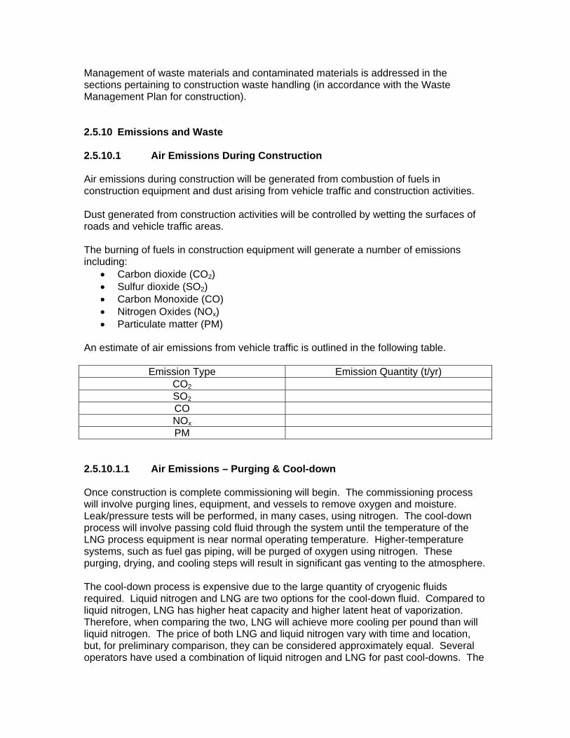
Management of waste materials and contaminated materials is addressed in the sections pertaining to construction waste handling (in accordance with the Waste Management Plan for construction). 2.5.10 Emissions and Waste 2.5.10.1 Air Emissions During Construction Air emissions during construction will be generated from combustion of fuels in construction equipment and dust arising from vehicle traffic and construction activities. Dust generated from construction activities will be controlled by wetting the surfaces of roads and vehicle traffic areas. The burning of fuels in construction equipment will generate a number of emissions including:
Carbon dioxide (CO2) Sulfur dioxide (SO2) Carbon Monoxide (CO) Nitrogen Oxides (NOx) Particulate matter (PM)
An estimate of air emissions from vehicle traffic is outlined in the following table.
Emission Type Emission Quantity (t/yr) CO2 SO2 CO NOx PM
2.5.10.1.1 Air Emissions – Purging & Cool-down Once construction is complete commissioning will begin. The commissioning process will involve purging lines, equipment, and vessels to remove oxygen and moisture. Leak/pressure tests will be performed, in many cases, using nitrogen. The cool-down process will involve passing cold fluid through the system until the temperature of the LNG process equipment is near normal operating temperature. Higher-temperature systems, such as fuel gas piping, will be purged of oxygen using nitrogen. These purging, drying, and cooling steps will result in significant gas venting to the atmosphere. The cool-down process is expensive due to the large quantity of cryogenic fluids required. Liquid nitrogen and LNG are two options for the cool-down fluid. Compared to liquid nitrogen, LNG has higher heat capacity and higher latent heat of vaporization. Therefore, when comparing the two, LNG will achieve more cooling per pound than will liquid nitrogen. The price of both LNG and liquid nitrogen vary with time and location, but, for preliminary comparison, they can be considered approximately equal. Several operators have used a combination of liquid nitrogen and LNG for past cool-downs. The
first phase cool-down is accomplished using liquid nitrogen while the second phase is accomplished using LNG. By using liquid nitrogen first and LNG second, purging steps are minimized. Additionally, using nitrogen first allows for relatively safe discovery/repair of leaks and lessens the greenhouse gas emissions associated with a complete LNG-based cool-down. The exact cool-down procedure will depend upon the construction and material details of the cryogenic process systems, especially the LNG storage tanks. The availability of liquid nitrogen to the construction site will also impact planning and logistics for cool-down. Pipe and Storage Tank Purge Since the cool-down process is envisioned to start with cold nitrogen vapor (oxygen removal is inherent), there should be minimal emissions for simple purging of the systems that will handle LNG or boil-off-gas. However, steps to ensure the piping systems are dry will also be necessary. Drying will also result in nitrogen emissions. There will be some pressure testing using nitrogen, but the emissions associated with pressure testing and drying are expected to be very small compared to cool-down emissions. The systems that do not require cool-down (some heat exchangers, fuel gas lines, etc) will also require pressure testing or purging, but, as in the cold system purging and pressure testing, emissions will be small relative to those of the cool-down process. When considering the preliminary nature of and possible error in the estimated cool-down fluid quantities shown below, the pressure test gas and purge gas emission quantities are not statistically significant. Facility Cool-down Transitioning (cool-down of) process equipment from ambient temperature to cryogenic temperature must be done in a careful, controlled manner. Simply introducing large amounts of LNG into warm piping, tanks, and equipment would create significant stress on the system and likely cause leaks or structural damage. Cool-down is accomplished by carefully introducing cold liquid or vapor into the system and allowing the cold stream to absorb heat from the system. Heat leaves the system as the, now warmer, cooling stream is vented. During cool-down there will necessarily be emissions of nitrogen or natural gas vapor (during some periods both). The LNG transshipment and storage facilities will be built in stages. Completion of the eight LNG tanks will occur in multiple future phases. The preliminary usage estimates for cool-down fluids shown below include requirements for the envisioned future phases of the project. If LNG process components are allowed to warm up significantly after the initial cool-down, the process must be repeated. Repeating the cool-down causes undesirable thermal cycling of the system’s components. The objective is to perform the cool-down operation just before or coincident with the first LNG tanker arrival and then maintain the system temperature, near -260oF (-162oC). There is uncertainty of schedule in all plant startups. The overall quantity of emissions that result from the cool-down and startup are dependent upon many factors.
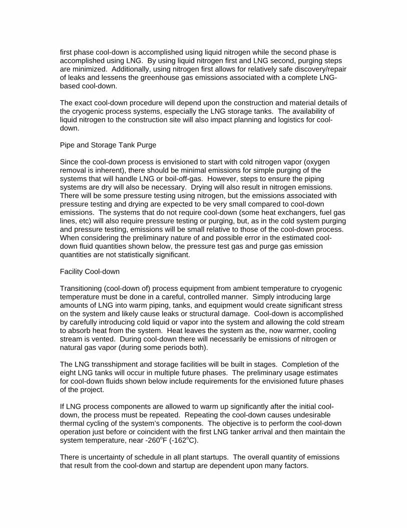
Preliminary Cool-down Fluid Usage Estimates Option Cool-down
Fluid Approximate Mass of Fluid for Cool-down and Purging Single LNG Tank, initial cool-down (kg)
Eight LNG Tanks, initial cool-down (kg)(1)
Major Piping, initial cool-down (kg)
1 N2 (15oC to -156oC)
4,350,000 34,800,000 2,250,000
LNG to Purge N2 after cool-down
12,500 100,000 6,400
2 N2 (15oC to -107oC)
2,350,000 18,800,000 1,200,000
LNG (-107oC to -156oC)
125,000 1,000,000 64,000
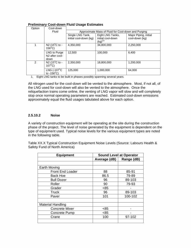
1. Eight LNG tanks to be built in phases possibly spanning several years. All nitrogen used for the cool-down will be vented to the atmosphere. Most, if not all, of the LNG used for cool-down will also be vented to the atmosphere. Once the reliquefaction trains come online, the venting of LNG vapor will slow and will completely stop once normal operating parameters are reached. Estimated cool-down emissions approximately equal the fluid usages tabulated above for each option. 2.5.10.2 Noise A variety of construction equipment will be operating at the site during the construction phase of the project. The level of noise generated by the equipment is dependent on the type of equipment used. Typical noise levels for the various equipment types are noted in the following table. Table XX.X Typical Construction Equipment Noise Levels (Source: Labours Health & Safety Fund of North America)
Equipment Sound Level at Operator Average (dB) Range (dB) Earth Moving
Front End Loader 88 85-91 Back Hoe 86.5 79-89 Bull Dozer 96 89-103 Roller 90 79-93 Grader <85 - Truck 96 89-103 Paver 101 100-102
Material Handling
Concrete Mixer <85 - Concrete Pump <85 - Crane 100 97-102
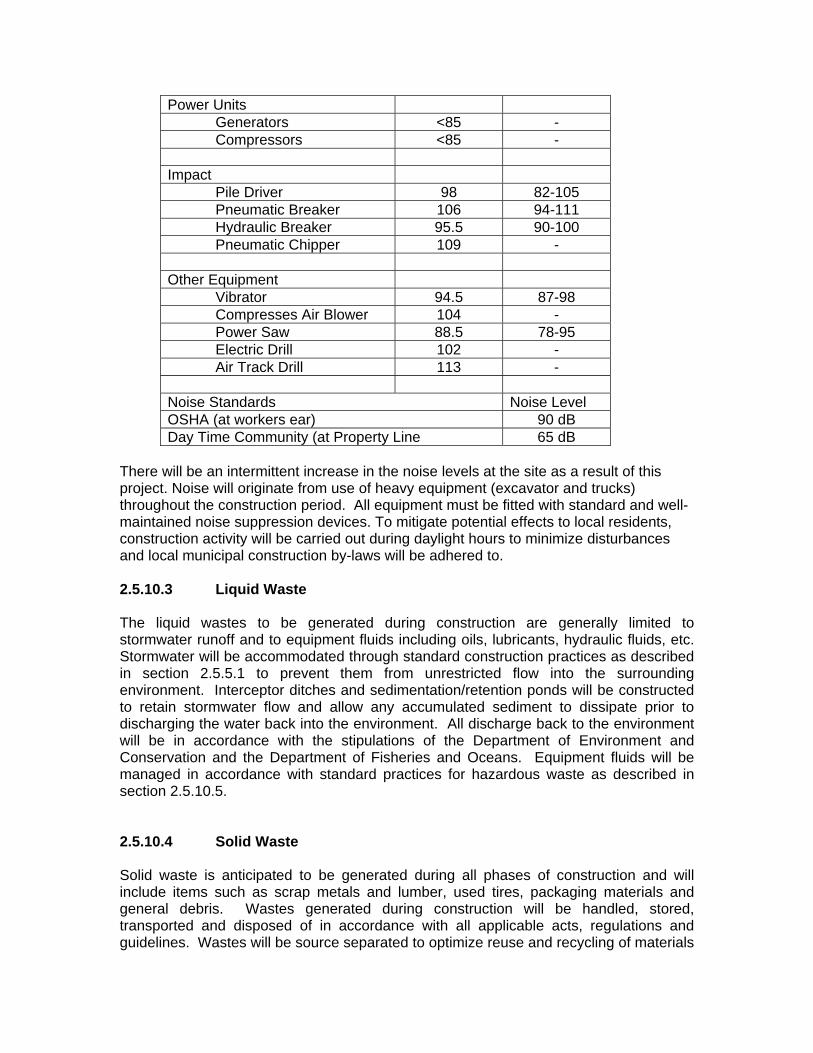
Power Units Generators <85 - Compressors <85 -
Impact
Pile Driver 98 82-105 Pneumatic Breaker 106 94-111 Hydraulic Breaker 95.5 90-100 Pneumatic Chipper 109 -
Other Equipment
Vibrator 94.5 87-98 Compresses Air Blower 104 - Power Saw 88.5 78-95 Electric Drill 102 - Air Track Drill 113 -
Noise Standards Noise Level OSHA (at workers ear) 90 dB Day Time Community (at Property Line 65 dB
There will be an intermittent increase in the noise levels at the site as a result of this project. Noise will originate from use of heavy equipment (excavator and trucks) throughout the construction period. All equipment must be fitted with standard and well-maintained noise suppression devices. To mitigate potential effects to local residents, construction activity will be carried out during daylight hours to minimize disturbances and local municipal construction by-laws will be adhered to. 2.5.10.3 Liquid Waste The liquid wastes to be generated during construction are generally limited to stormwater runoff and to equipment fluids including oils, lubricants, hydraulic fluids, etc. Stormwater will be accommodated through standard construction practices as described in section 2.5.5.1 to prevent them from unrestricted flow into the surrounding environment. Interceptor ditches and sedimentation/retention ponds will be constructed to retain stormwater flow and allow any accumulated sediment to dissipate prior to discharging the water back into the environment. All discharge back to the environment will be in accordance with the stipulations of the Department of Environment and Conservation and the Department of Fisheries and Oceans. Equipment fluids will be managed in accordance with standard practices for hazardous waste as described in section 2.5.10.5. 2.5.10.4 Solid Waste Solid waste is anticipated to be generated during all phases of construction and will include items such as scrap metals and lumber, used tires, packaging materials and general debris. Wastes generated during construction will be handled, stored, transported and disposed of in accordance with all applicable acts, regulations and guidelines. Wastes will be source separated to optimize reuse and recycling of materials
where possible. Migration of wastes from the site will not be permitted, and all wastes will be collected and properly contained. Domestic wastes will be stored so that animals insects or other vectors are not attracted to the site. Wastes that may cause leachate will be stored on an impermeable pad and contained within a structure that prevents exposure to precipitation and runoff. Odorous wastes will be treated and stored so that odour problems are prevented. Solid waste that cannot be reused or recycled will be transported to existing, approved, off-site waste management facilities by certified contractors. Removal of waste materials will be done on a routine basis to prevent accumulation at the project site. Wastes will not be permitted to enter or come in contact with watercourses or wetlands. 2.5.10.5 Hazardous Waste As part of routine construction activities, hazardous materials will be used and hazardous waste will consequently be generated. Similar to the solid waste objective for the project, a program of careful product selection and targeting of products that can be recycled will be used during construction to minimize the generation of hazardous waste. All hazardous materials will be handled and stored on site in accordance with WHMIS regulations. All hazardous waste generated on-site during operations will be disposed off-site in accordance with regulatory requirements. Personnel training will be an important aspect of the waste management plan for hazardous wastes, and all workers will be trained in safe management practices. Training and worker awareness will result in minimizing accidents such as spills, improper storage of waste materials and inappropriate disposal techniques. Hazardous solid wastes that may be generated during construction include:
Propane Oxygen, acetylene and other compressed gases Gasoline Diesel fuel Grease Lubricants Engine oil Hydraulic fluids Form oil Paints and coatings Epoxies Concrete additives Glycol/methanol Cleaners Solvents Explosives Blasting Caps Detonators Liquid Asphalt/tars Sodium Hypochlorite Sodium Thiosulphate
Batteries Contaminated soils, rock and vegetation
Temporary facilities will be built for the construction period as required to provide storage for these waste materials prior to disposal, and to provide areas for equipment servicing to control waste hazardous materials. The location of hazardous waste storage will be identified on a construction drawing to provide current information to workers present at the site. 2.5.10.6 Septic Waste Portable sanitary facilities will be used for domestic sanitation during construction. Wastes from these facilities will be collected and disposed by an approved contractor licensed by the province for that work. Portable toilet facilities will be installed in accordance with the stipulations of Occupational Health and Safety Regulations of Canada and the province. No discharge of septic waste will be permitted on site or in any unauthorized facility.