Embed Size (px)
Citation preview

25
/05
/20
10 R
D5
1 C
oll
ab
ora
tio
n M
ee
tin
gC
isb
an
i-M
usi
co
-Min
uto
li /
Sta
tus
JL
ab E
lec
tro
nic
s
1
Status of the APV25 electronics for the GEM tracker at JLab
Evaristo Cisbani - INFN/Rome & Italian National Institute of Health
On behalf of:
Paolo Musico, Saverio Minutoli, Giuseppe Gariano - INFN/GE
Freiburg 25/May/10
WG5-RD51 Collaboration Meeting

25
/05
/20
10 R
D5
1 C
oll
ab
ora
tio
n M
ee
tin
gC
isb
an
i-M
usi
co
-Min
uto
li /
Sta
tus
JL
ab E
lec
tro
nic
s
2
New SBS Spectrometer @ JLab
hallaweb.jlab.org/12GeV/SuperBigBite/
GEP5 setup
Two tracker geometries:
1. front tracker
2. second and third tracker
will use the same “base module”
• High Luminosity: 1038 /cm2/s
• Support high background:
500 kHz/cm2 (low energy
photons mainly)
• Forward angle
• Large acceptance
• Good angular and momentum
resolutions:
0.2 mrad, 0.5% @ 4-8 GeV/c
• Flexibility:
use the same detectors in
different experimental setup
• High Luminosity: 1038 /cm2/s
• Support high background:
500 kHz/cm2 (low energy
photons mainly)
• Forward angle
• Large acceptance
• Good angular and momentum
resolutions:
0.2 mrad, 0.5% @ 4-8 GeV/c
• Flexibility:
use the same detectors in
different experimental setup

25
/05
/20
10 R
D5
1 C
oll
ab
ora
tio
n M
ee
tin
gC
isb
an
i-M
usi
co
-Min
uto
li /
Sta
tus
JL
ab E
lec
tro
nic
s
3
SBS Tracker Chambers configuration
Modules are composed to form larger
chambers with different sizes Electronics along the borders and
behind the frame (at 90°) – cyan and
blue in drawing
Aluminum support frame around the
chamber (cyan in drawing); dedicated
to each chamber configuration
Front TrackerGeometry
x6
Back Trackers Geometry
X(4+4)
GEp(5) SBS

25
/05
/20
10 R
D5
1 C
oll
ab
ora
tio
n M
ee
tin
gC
isb
an
i-M
usi
co
-Min
uto
li /
Sta
tus
JL
ab E
lec
tro
nic
s
4
GEM Trackers Accounting
Tracker Area
(cm2)
Number of Chambers
Readout Pitch
(mm)
Modules/Chamber
Total Modules
Total Readout Channels
FT 40x150 6 2D
4(x/y) 2(u/v)
0.4 1×3 18 49000
+
13500
ST
+
TT
50x200 4 + 4 2D
2(x/y) 2(u/v)
4×0.4 1×5 20+20 13600
+
13600
CD 80x300 2 1D
y+y
1.0 2×6 24 12000
Last 2 FT modules with strips split in the middle (double segmentation on each site)
ST and TT readout groups 4 strips in GEp(5) with binary readout
Total chs. 101700

25
/05
/20
10 R
D5
1 C
oll
ab
ora
tio
n M
ee
tin
gC
isb
an
i-M
usi
co
-Min
uto
li /
Sta
tus
JL
ab E
lec
tro
nic
s
5
2D Readout Plane and ZIF extension
Readout along all sides
− not strictly required in x/y
unless additional segmentation
of the readout plane
− weight balance
− unavoidable in diagonal u/v
Extension feeds into ZIF
connectors:
− no soldering on the readout foil
− permit safer bending
Small frame width (8 mm);
minimize dead area
• Require precise cutting around the
ZIF terminalsRui De Oliveira final design based
on our drawing
x/y
In production (almost done)

25
/05
/20
10 R
D5
1 C
oll
ab
ora
tio
n M
ee
tin
gC
isb
an
i-M
usi
co
-Min
uto
li /
Sta
tus
JL
ab E
lec
tro
nic
s
6
Electronics Components
GEM FEC ADC+VME Controller DAQ
Main features:• Use analog readout APV25 chips• 2 active components: Front-End card and VME64x custom module • Copper cables between front-end and VME
2D R
eado
ut
Thanks to Michael Böhmer and Igor Konorov from TUMfor very productive discussions on the design of the APV25 based FrontEnd card
Up to 10m
75 mm
49.5
mm
8 mm
FOTO MODULO VME
25
/05
/20
10 R
D5
1 C
oll
ab
ora
tio
n M
ee
tin
gC
isb
an
i-M
usi
co
-Min
uto
li /
Sta
tus
JL
ab E
lec
tro
nic
s
7
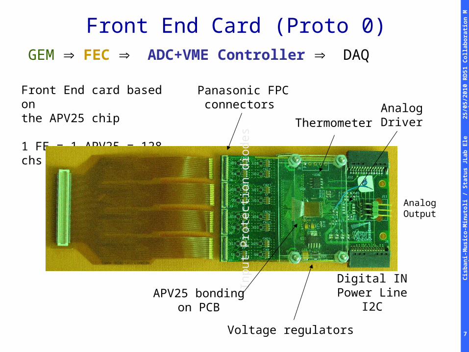
Front End Card (Proto 0)
GEM FEC ADC+VME Controller DAQ
Front End card based onthe APV25 chip
1 FE = 1 APV25 = 128 chs
AnalogOutput
Panasonic FPCconnectors
Inpu
t P
rote
ctio
n di
odes
APV25 bondingon PCB
Voltage regulators
AnalogDriverThermometer
Digital INPower Line
I2C

25
/05
/20
10 R
D5
1 C
oll
ab
ora
tio
n M
ee
tin
gC
isb
an
i-M
usi
co
-Min
uto
li /
Sta
tus
JL
ab E
lec
tro
nic
s
8
Front-end prototypes tests
50 cm cable
7 m cable
• Front-end card under control
• First tests on analog cable length positive
• No analog driver
Work is in progress

25
/05
/20
10 R
D5
1 C
oll
ab
ora
tio
n M
ee
tin
gC
isb
an
i-M
usi
co
-Min
uto
li /
Sta
tus
JL
ab E
lec
tro
nic
s
9
Front-End new version (Proto 1)
• Bug fixing of previous version
• Denser Bonding: 50 um pad, 100 um pitch
• Backplane connector(back side)
• 5 mm shorter
• Under production

25
/05
/20
10 R
D5
1 C
oll
ab
ora
tio
n M
ee
tin
gC
isb
an
i-M
usi
co
-Min
uto
li /
Sta
tus
JL
ab E
lec
tro
nic
s
10
Front-End adapter card (for testing)
• LEMO/TTL to Differential
• Differential Analog to Differential LEMO
• USB to I2C
• Single 3.3 V power line
• Very simple but useful

25
/05
/20
10 R
D5
1 C
oll
ab
ora
tio
n M
ee
tin
gC
isb
an
i-M
usi
co
-Min
uto
li /
Sta
tus
JL
ab E
lec
tro
nic
s
11
Electronic layout on one chamber
Cards and modules are supported by an outer carbon-fiber frame which runs all around the chamber.
Optimization is in progress.
A C
B
D

25
/05
/20
10 R
D5
1 C
oll
ab
ora
tio
n M
ee
tin
gC
isb
an
i-M
usi
co
-Min
uto
li /
Sta
tus
JL
ab E
lec
tro
nic
s
12
FE – Backplane - VME
• Next release will use a rigid PCB backplane for analog
and digital lines (keep the cable option for testing
• Backplane is the mechanical supports for the vertical
cards in between two GEM modules
•Controlled
impedance
25
/05
/20
10 R
D5
1 C
oll
ab
ora
tio
n M
ee
tin
gC
isb
an
i-M
usi
co
-Min
uto
li /
Sta
tus
JL
ab E
lec
tro
nic
s
13
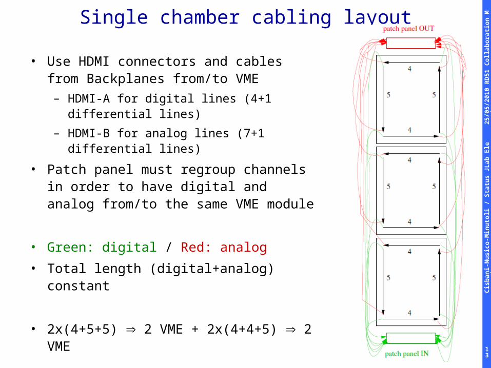
Single chamber cabling layout
• Use HDMI connectors and cables from Backplanes from/to VME
– HDMI-A for digital lines (4+1 differential lines)
– HDMI-B for analog lines (7+1 differential lines)
• Patch panel must regroup channels in order to have digital and analog from/to the same VME module
• Green: digital / Red: analog
• Total length (digital+analog) constant
• 2x(4+5+5) 2 VME + 2x(4+4+5) 2 VME

25
/05
/20
10 R
D5
1 C
oll
ab
ora
tio
n M
ee
tin
gC
isb
an
i-M
usi
co
-Min
uto
li /
Sta
tus
JL
ab E
lec
tro
nic
s
14
VME64x Controller VME controller hosts the digitization of the analog
signals coming from the front-end card. It handle all control signals required by the front end
cards (up to 16 FE) Compliant to the new JLab/12 VME64x VITA 41 (VXS)
standard We intend to make it accessible by standard VME as
well Modular design: with the possibility to easily detach the
analog module to extend FEC-VME64x distance Under TEST
From the VXS backplane:
1. Trigger L1/L2
2. Synch
3. Clock
4. Busy (OUT)
(duplicated on front panel)
Digital OUT
16 Analog INAnalog
Receivers
ADCs50 MHz12 bits
USB
ETH
Optical Fiber
2x64MbyteSDRAM
Live InsertionHot-Swap
Oscillators(100 MHz, 62.5 MHz)
Flash EPROM
Thermometer
Voltage Regulatorsfor each module

25
/05
/20
10 R
D5
1 C
oll
ab
ora
tio
n M
ee
tin
gC
isb
an
i-M
usi
co
-Min
uto
li /
Sta
tus
JL
ab E
lec
tro
nic
s
15
• Firmware on Verilog (under test):– VME-32 bit interface (64-bit interface very preliminary)– USB-interface (VME and USB share the same
resources) – PLL configuration interface (APV-ADC clock phasing) – I2C master interface– Trigger handler (very simple) via front panel LEMO– ADC serial configuration interface and de-serializer– APV25 frame decoder; value stored on a FIFO
accessible from VME and USB.– Single channel histogram (useful for delay tuning ...)– Front end test signals generator
VME64x Controller / ALTERA Firmware
25
/05
/20
10 R
D5
1 C
oll
ab
ora
tio
n M
ee
tin
gC
isb
an
i-M
usi
co
-Min
uto
li /
Sta
tus
JL
ab E
lec
tro
nic
s
16
Conclusions
• Front-end card prototype 0: tested, bug fixed and
improvement defined
• Front-end card prototype 1: under production
• VME-controller prototype 0:
– everything mounted except VME transceivers
– most of the firmware modules implemented
– under heavy test
• Expect to install in GEM module (40x50cm2) end of June
– test in July
• Usable system expected September/2010