Embed Size (px)
Citation preview
5/13/2018 25690825 Retaining Walls - slidepdf.com
http://slidepdf.com/reader/full/25690825-retaining-walls 1/70
CARMEL B. SABADO CE-162 PROF. GERONIDES P. ANCOG
BSCE-5 2nd Excel Program ###
*note:the boxes in yellow should be inputed by the designer,while blue ones are computed by the program.
****====DESIGN OF GRAVITY RETAINING WALL====****
f, coefficient
1. Soil or gravel without fine particle 17.25 - 18.85 33 -40 0.5 -0.6
highly permeable.
2. Sand or gravel with silt mixture, l 18.85 - 20.40 25 - 35 0.4 - 0.5
permeability
3. Silty sand, sand and gravel with h 17.25 - 18.85 23 - 30 0.3 - 0.4
clay content
4. Medium or stiff clay 15.70 - 18.85 25 - 35 0.2 - 0.4
5. Soft clay, silt 14.10 - 17.25 20 -25 0.2 - 0.3
0.5 m
qs =20 kPa
3.50 m
0 .
2 5
0 .
2 5
1.10 m 0.60 m
Solutio (Use class 2 of the table given above)
Composite Section
3.50 m
1.10 m
Soil pressure coefficient, Rankine equation for horizontal soil surface30° Passive soil pressure coefficient
18.85 kN/m³
qs = 20.00 kPa = 3.00
h' = 1.061 m
Distances computation
Active soil pressure coefficient 2.0000 m
0.1250m
= 0.33 0.5000 m
1.7500m
3.8750m
w, kN/m³ φ, degrees
Table 1: Unit weights w, effective angles of internal friction φ, and coefficients of friction with con
φ =
w =
c1
= B/2 =
c2
= e/2 =
c3
= e + a/2 =
c4
= (B - 2e - a)/3 + e + a =
c5 = B - e + e/2 =
W 7
c7
a
W 3c5
W 1
W 2
W 4
W 5
W 6
c1
c2
c3 c
4
c6
h '
h
e
B
d
C ah=1−sinφ
1sinφ
C ph=1sinφ
1−sinφ
5/13/2018 25690825 Retaining Walls - slidepdf.com
http://slidepdf.com/reader/full/25690825-retaining-walls 2/70
2.7500m
2.3750m
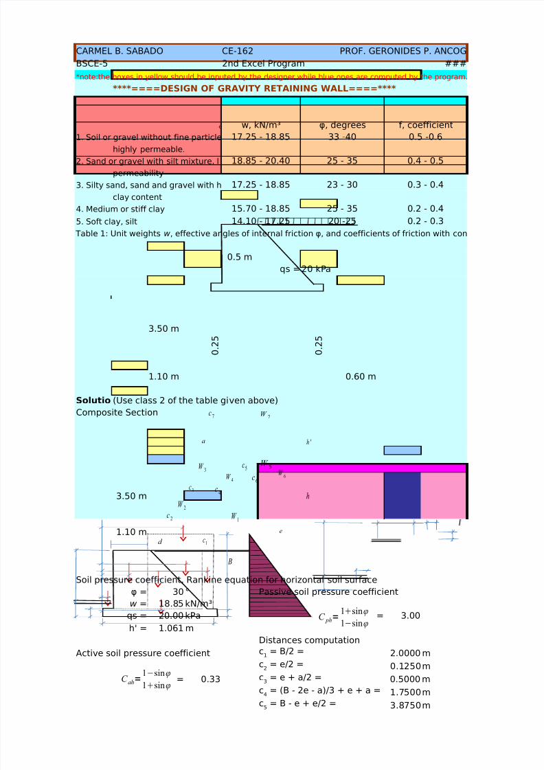
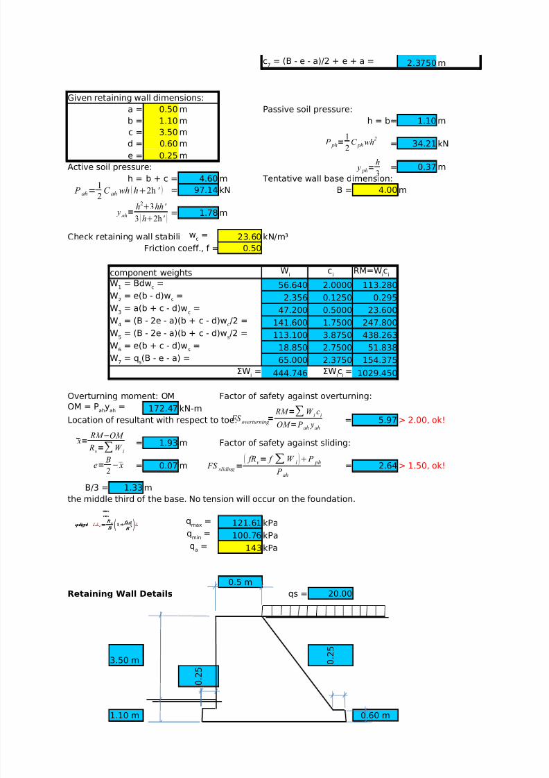
Given retaining wall dimensions:
a = 0.50m Passive soil pressure:
b = 1.10m h = b= 1.10 m
c = 3.50md = 0.60m = 34.21 kN
e = 0.25m
Active soil pressure: = 0.37 m
h = b + c = 4.60m Tentative wall base dimension:
= 97.14 kN B = 4.00 m
= 1.78 m
Check retaining wall sta 23.60 kN/m³
Friction coeff., f 0.50
component weights
56.640 2.0000 113.280
2.356 0.1250 0.295
47.200 0.5000 23.600
141.600 1.7500 247.800
113.100 3.8750 438.263
18.850 2.7500 51.838
65.000 2.3750 154.375444.746 1029.450
Overturning moment: OM Factor of safety against overturning:
172.47 kN-m
Location of resultant with respect to toe: = 5.97> 2.00, ok!
= 1.93m Factor of safety against sliding:
= 0.07m = 2.64 > 1.50, ok!
B/3 = 1.33 m
the middle third of the base. No tension will occur on the foundation.
121.61kPa
100.76kPa
143 kPa
qmax < qa, the wall is safe against soil bearing.
0.5 m
Retaining Wall Details qs =20 kPa
3.50 m
0 .
2 5
0 .
2 5
c6
= (B - 2e - a)2/3 + e + a
c7
= (B - e - a)/2 + e + a =
wc=
Wi
ci
RM=Wic
i
W1
= Bdwc=
W2
= e(b - d)ws=
W3
= a(b + c - d)wc=
W4
= (B - 2e - a)(b + c - d)wc/2 =
W5
= (B - 2e - a)(b + c - d)ws/2 =
W6
= e(b + c - d)ws=
W7 = qs(B - e - a) =ΣW
i= ΣW
ic
i=
OM = Pah
yah
=
qmax
=
qmin
=
qa
=
P ah=1
2C ahwh h2h '
yah=
h23hh '
3 h2h '
P ph=1
2C ph wh
2
y ph=h
3
x=RM −OM
Rv=∑W i
e= B
2
− x
max
min
qalignl ¿¿ ¿= R
v
B 1±6 e
B2 ¿
FS overturning
= RM =∑W
ic
i
OM = P ah yah
FS sliding
= fRv= f ∑W i P ph
P ah

5/13/2018 25690825 Retaining Walls - slidepdf.com
http://slidepdf.com/reader/full/25690825-retaining-walls 3/70
1.10 m 0.60 m
4.00m

5/13/2018 25690825 Retaining Walls - slidepdf.com
http://slidepdf.com/reader/full/25690825-retaining-walls 4/70
. =)
crete f.

5/13/2018 25690825 Retaining Walls - slidepdf.com
http://slidepdf.com/reader/full/25690825-retaining-walls 5/70

5/13/2018 25690825 Retaining Walls - slidepdf.com
http://slidepdf.com/reader/full/25690825-retaining-walls 6/70
5/13/2018 25690825 Retaining Walls - slidepdf.com
http://slidepdf.com/reader/full/25690825-retaining-walls 7/70
CARMEL B. SABADO CE-162 PROF. GERONIDES P. ANCOG
BSCE-5 2nd Excel Program ###
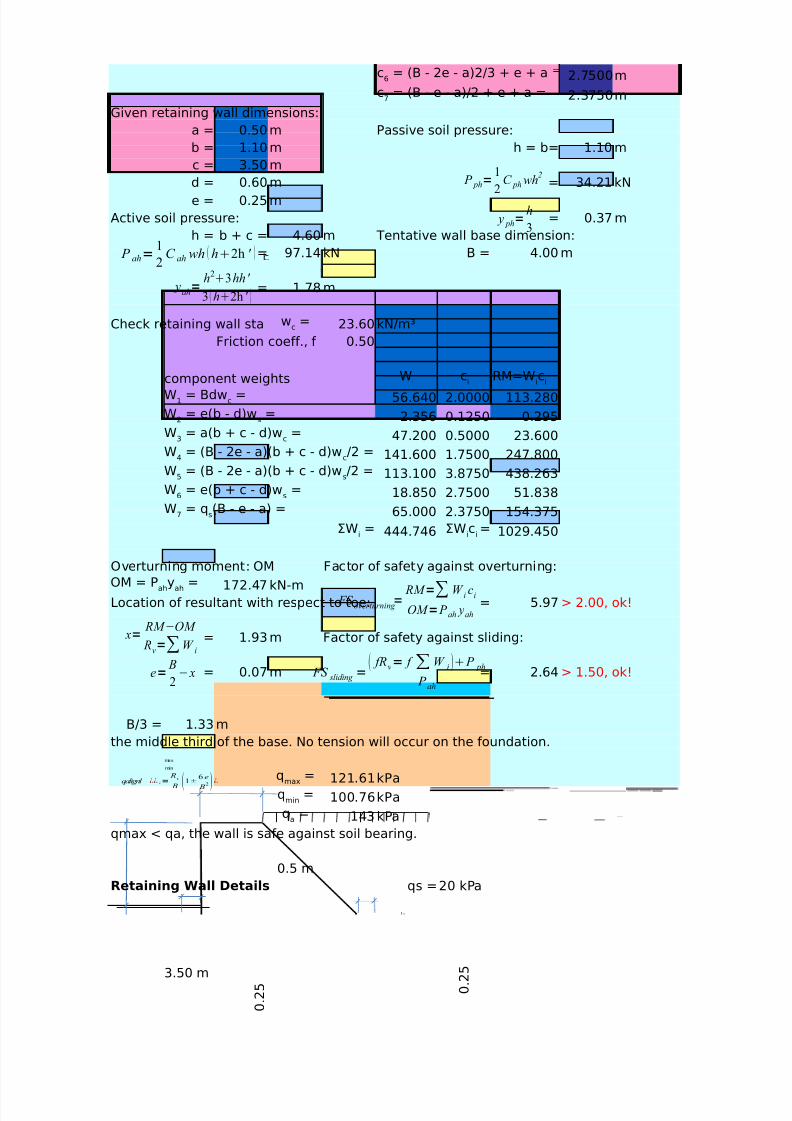
****====DESIGN OF GRAVITY RETAINING WALL====****
f, coefficient
1. Soil or gravel without fine particles, 17.25 - 18.85 33 -40 0.5 -0.6
highly permeable.
2. Sand or gravel with silt mixture, low 18.85 - 20.40 25 - 35 0.4 - 0.5
permeability
3. Silty sand, sand and gravel with high 17.25 - 18.85 23 - 30 0.3 - 0.4
clay content
4. Medium or stiff clay 15.70 - 18.85 25 - 35 0.2 - 0.4
5. Soft clay, silt 14.10 - 17.25 20 -25 0.2 - 0.3
*note:the boxes in yellow should be inputed by the designer,while blue ones are c
computed by the program. 0.5 m
qs =20 kPa
3.50 m
0 . 2
5
0 . 2
5
1.10 m 0.60 m
Solution:(Use class 2 of the table given above)
Composite Section
3.50 m
1.10 m
Soil pressure coefficient, Rankine equation for horizontal soil surface
30 ° Passive soil pressure coefficient18.85kN/m³
qs = 20.00 kPa = 3.00
h' = 1.061 m
Distances computation
Active soil pressure coefficient 2.0000 m
0.1250m
= 0.33 0.5000 m
1.7500m
3.8750m
2.7500m
Table 1: Unit weights w, effective angles of internal friction φ, and coefficients of friction with concrete f.
w, kN/m³ φ, degrees
φ =w =
c1
= B/2 =
c2
= e/2 =
c3
= e + a/2 =
c4
= (B - 2e - a)/3 + e + a =
c5
= B - e + e/2 =
c6 = (B - 2e - a)2/3 + e + a =
W 7
c7
a
W 3c5
W 1
W 2
W 4
W 5
W 6
c1
c2
c3 c
4
c6
h '
h
e
B
d
C ah=1−sinφ
1sinφ
C ph=1sinφ
1−sinφ
W 7
c7
a
W 3c5
W 1
W 2
W 4
W 5
W 6
c1
c2
c3 c
4
c6
h '
h
e
B
d
5/13/2018 25690825 Retaining Walls - slidepdf.com
http://slidepdf.com/reader/full/25690825-retaining-walls 8/70
2.3750m
Given retaining wall dimensions:
a = 0.50 m Passive soil pressure:
b = 1.10 m h = b= 1.10 mc = 3.50 m
d = 0.60 m = 34.21 kN
e = 0.25 m
Active soil pressure: = 0.37 m
h = b + c = 4.60 m Tentative wall base dimension:
= 97.14 kN B = 4.00 m
= 1.78 m
Check retaining wall stabili 23.60 kN/m³Friction coeff., f = 0.50
component weights
56.640 2.0000 113.280
2.356 0.1250 0.295
47.200 0.5000 23.600
141.600 1.7500 247.800
113.100 3.8750 438.263
18.850 2.7500 51.838
65.000 2.3750 154.375
444.746 1029.450
Overturning moment: OM Factor of safety against overturning:
172.47 kN-m
Location of resultant with respect to toe: = 5.97 > 2.00, ok!
= 1.93 m Factor of safety against sliding:
= 0.07 m = 2.64 > 1.50, ok!
B/3 = 1.33 m
the middle third of the base. No tension will occur on the foundation.
121.61 kPa
100.76 kPa
143kPa
0.5 m
Retaining Wall Details qs = 20.00
3.50 m 0 .
2 5
0 .
2 5
1.10 m 0.60 m
c7
= (B - e - a)/2 + e + a =
wc =
Wi
ci
RM=Wic
i
W1
= Bdwc=
W2
= e(b - d)ws=
W3
= a(b + c - d)wc=
W4
= (B - 2e - a)(b + c - d)wc/2 =
W5
= (B - 2e - a)(b + c - d)ws/2 =
W6
= e(b + c - d)ws=
W7
= qs(B - e - a) =
ΣWi= ΣW
ic
i=
OM = Pah
yah
=
qmax
=
qmin
=
qa
=
P ah=1
2C ah wh h2h '
yah=
h23hh '
3 h2h '
x=RM −OM
Rv=∑W
i
e= B
2
− x
max
min
qalignl ¿¿¿= R
v
B 1±6 e
B2 ¿
FS overturning =
RM =∑W ic
i
OM = P ah yah
FS sliding
= fRv= f ∑W i P ph
P ah
P ph=1
2C ph wh
2
y ph=h
3
max
min
qalignl ¿¿¿= R
v
B 1±6 e
B2 ¿
5/13/2018 25690825 Retaining Walls - slidepdf.com
http://slidepdf.com/reader/full/25690825-retaining-walls 9/70
4.00m
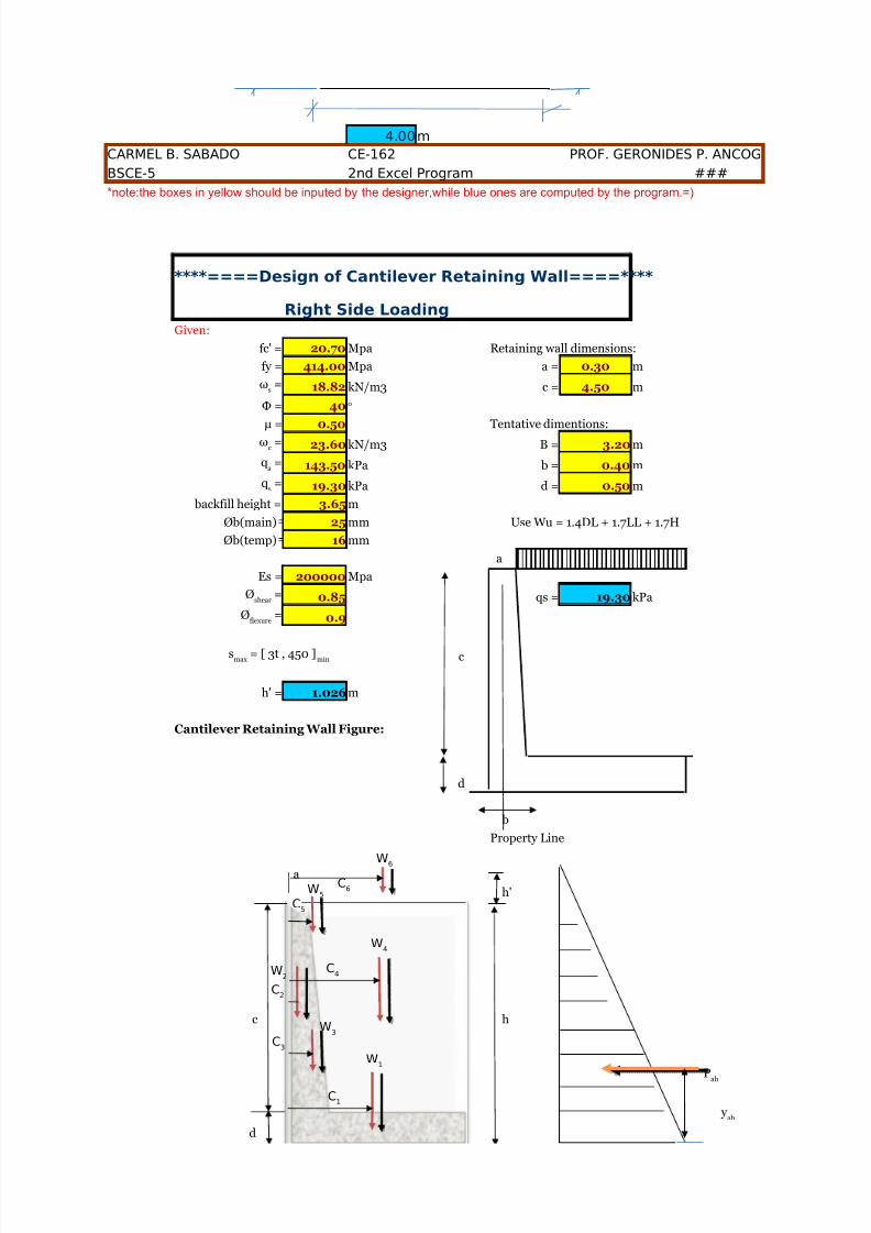
CARMEL B. SABADO CE-162 PROF. GERONIDES P. ANCOG
BSCE-5 2nd Excel Program ###
*note:the boxes in yellow should be inputed by the designer,while blue ones are computed by the program.=)
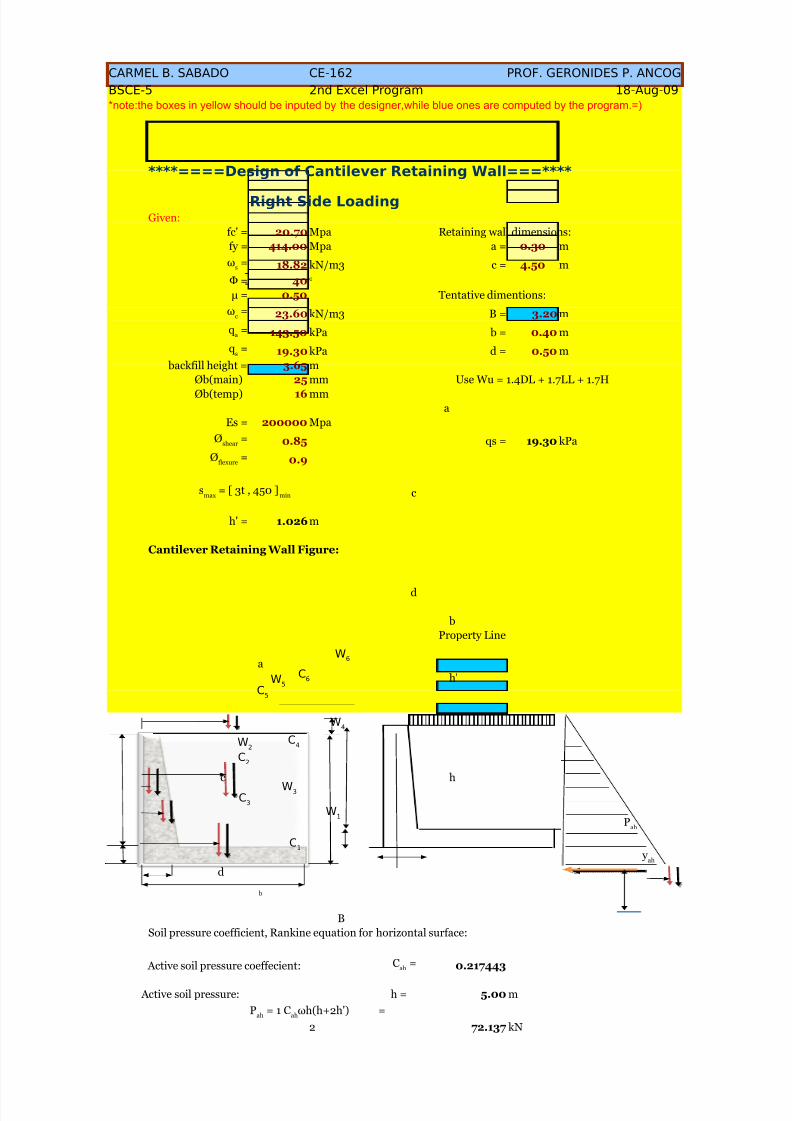
****====Design of Cantilever Retaining Wall====****
Right Side Loading
Given:
fc' = 20.70 Mpa Retaining wall dimensions:
fy = 414.00 Mpa a = 0.30 m
18.82 kN/m3 c = 4.50 m
Φ = 40
μ = 0.50 Tentative dimentions:
23.60 kN/m3 B = 3.20 m
143.50 kPa b = 0.40 m
19.30 kPa d = 0.50 m
backfill height = 3.65 m
Øb(main) 25 mm Use Wu = 1.4DL + 1.7LL + 1.7H
Øb(temp) 16 mm
aEs = 200000 Mpa
0.85 qs = 19.30 kPa
0.9
c
h' = 1.026 m
Cantilever Retaining Wall Figure:
d
b
Property Line
a
h'
c h
d
ωs
=
o
ωc
=
qa
=
qs
=
Øshear
=
Øflexure
=
smax
= [ 3t , 450 ]min
Pah
y
ah
W1
C1
W2
C2
W3
W4
W5
C3
C4
C5
W6
C6
5/13/2018 25690825 Retaining Walls - slidepdf.com
http://slidepdf.com/reader/full/25690825-retaining-walls 10/70
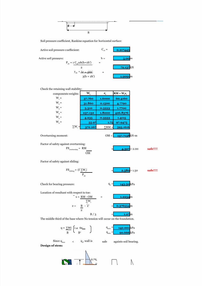
B
Soil pressure coefficient, Rankine equation for horizontal surface:
Active soil pressure coeffecient: 0.217443
Active soil pressure: h = 5.00 m
2 72.137 kN
3(h + 2h') 1.9091 m
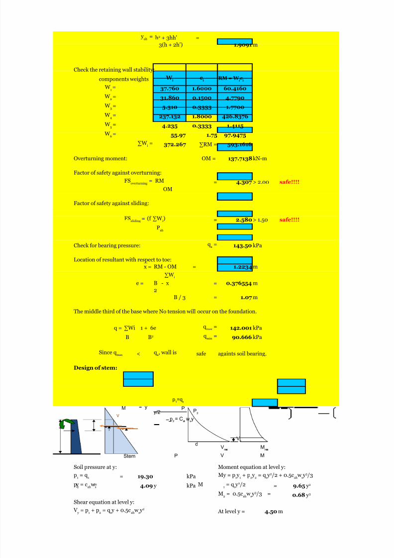
Check the retaining wall stability:
components weights
37.760 1.6000 60.4160
31.860 0.1500 4.7790
5.310 0.3333 1.7700
237.132 1.8000 426.8376
4.235 0.3333 1.4115
55.97 1.75 97.9475
372.267 ∑RM = 593.1616
Overturning moment: OM = 137.7138kN-m
Factor of safety against overturning:
= 4.307 > 2.00 safe!!!!
OM
Factor of safety against sliding:
= 2.580 > 1.50 safe!!!!
Check for bearing pressure: 143.50 kPa
Location of resultant with respect to toe:
x = RM - OM = 1.2234 m
e = B - x = 0.376554 m
2
B / 3 = 1.07 m
The middle third of the base where No tension will occur on the foundation.
q = 142.001 kPa
90.666 kPa
< safe againts soil bearing.
Design of stem:
b
Cah
=
Pah
= 1 Cah
ωh(h+2h') =
y ah
= h2 + 3hh' =
W i
ci
RM = W ic
i
W 1=
W 2=
W 3=
W 4=
W 5=
W 6=
∑W i=
FSoverturning
= RM
FSsliding
= (f ∑W i)
Pah
qa =
∑W i
∑Wi 1 + 6e qmax
=
B B2 qmin
=
Since qmax
qa, wall is
p1=qs
5/13/2018 25690825 Retaining Walls - slidepdf.com
http://slidepdf.com/reader/full/25690825-retaining-walls 11/70
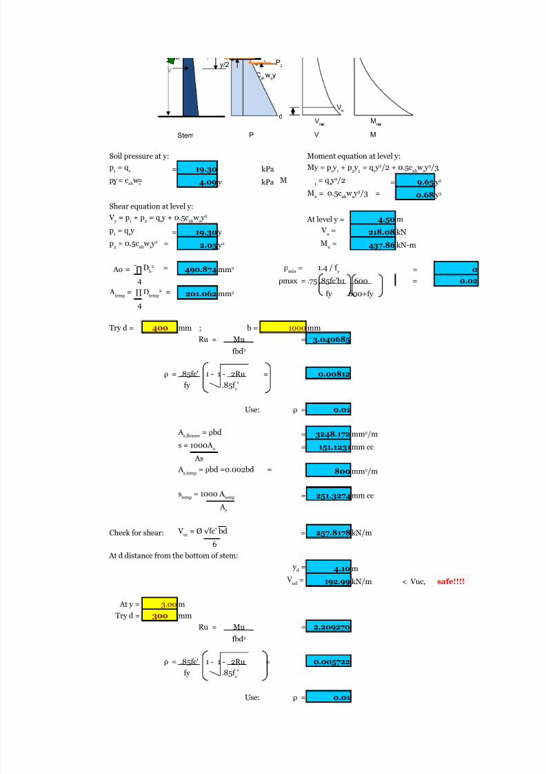
Soil pressure at y: Moment equation at level y:
= 19.30 kPa
4.09 y kPa = 9.65
0.68
Shear equation at level y:
At level y = 4.50 m
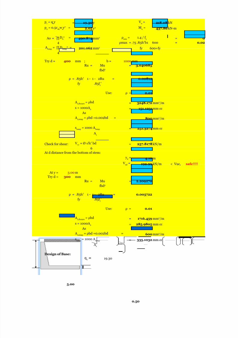
= 19.30 y 218.08 kN2.05 437.86 kN-m
490.874 = 0
4 ρmax = = 0.02
201.062 fy 600+fy
4
Try d = 400 mm ; b = 1000 mm
Ru = Mu = 3.040685
ρ = 0.00812
Use: ρ = 0.01
= 3248.172
= 151.1231mm cc
As
800
= 251.3274mm cc
Check for shear: = 257.8178kN/m
6
At d distance from the bottom of stem:
4.10 m
192.99 kN/m < Vuc, safe!!!!
At y = 3.00 m
Try d = 300 mm
Ru = Mu = 2.209270
ρ = 0.005722
Use: ρ = 0.01
p1
= qs
My = p1 y
1+ p
2 y
2= q
s y 2/2 + 0.5c
ah w
s y 3/3
p2 = cah w s y = M 1 = qs y 2/2 y 2
M2
= 0.5cah w
s y 3/3 = y 3
V y
= p1
+ p2
= qs y + 0.5c
ah w
s y 2
p1
= qs y V
u=
p2
= 0.5cah w
s y 2 = y 2 M
u=
Ao = ∏ D b
2 = mm2 ρmin
=
1.4 / f y
.75 .85fc'b1 600
A temp
= ∏ Dtemp
2 = mm2
fbd2
.85fc' 1 - 1 - 2Ru =
fy .85f c'
A s,flexure
= ρbd mm2/m
s = 1000A o
A s,temp = ρbd =0.002bd = mm2/m
stemp
= 1000 A temp
A s
V uc
= Ø √fc' bd
y d
=
V ud
=
fbd2
.85fc' 1 - 1 - 2Ru =
fy .85f c'
Ve
1 P2
p2= C
ahw
sy
y/2V
d Vmax
Mmax
Stem P MV
5/13/2018 25690825 Retaining Walls - slidepdf.com
http://slidepdf.com/reader/full/25690825-retaining-walls 12/70
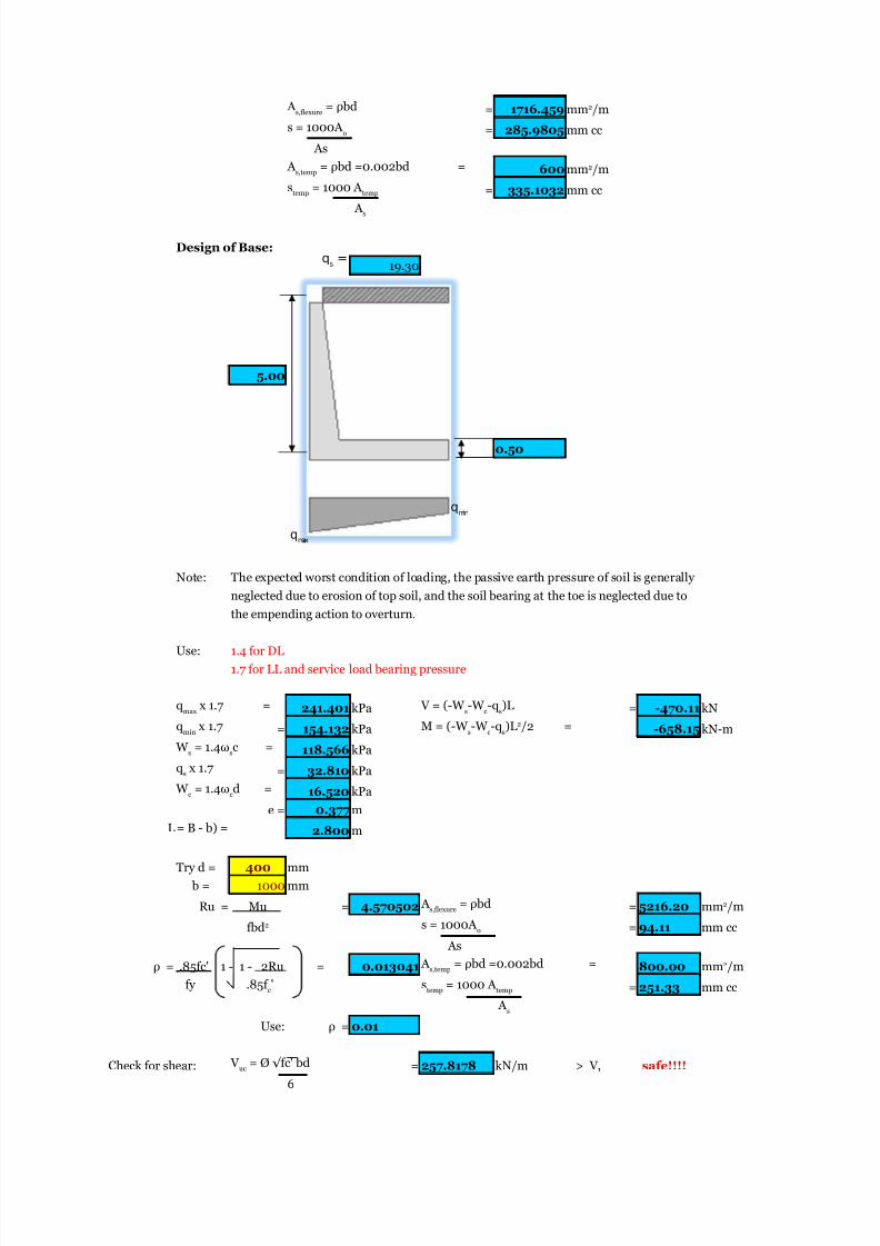
= 1716.459
= 285.9805 mm cc
As
600
= 335.1032 mm cc
Design of Base:
19.30
5.00
0.50
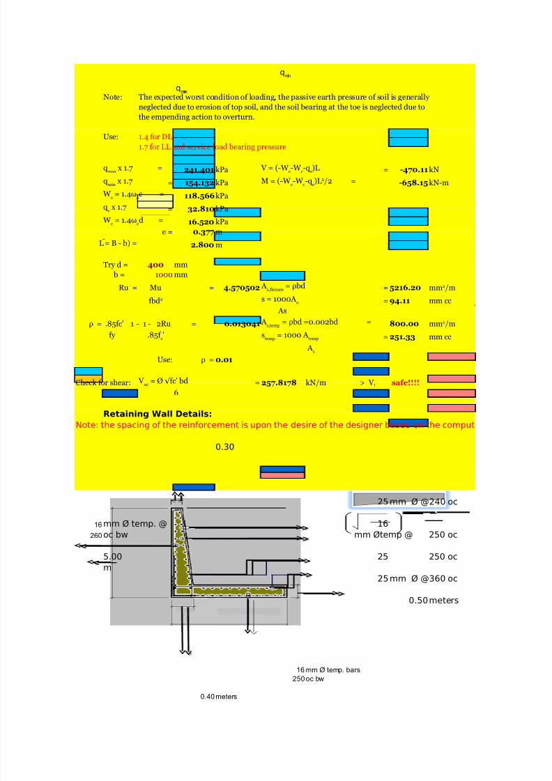
Note: The expected worst condition of loading, the passive earth pressure of soil is generally
neglected due to erosion of top soil, and the soil bearing at the toe is neglected due to
the empending action to overturn.
Use: 1.4 for DL
1.7 for LL and service load bearing pressure
241.401 kPa = -470.11 kN
= 154.132 kPa -658.15 kN-m
118.566 kPa= 32.810 kPa
16.520 kPa
e = 0.377 m
2.800 m
Try d = 400 mm
b = 1000 mm
Ru = Mu = 4.570502 = 5216.20
= 94.11 mm cc
Asρ = 0.013041 800.00
= 251.33 mm cc
Use: ρ = 0.01
Check for shear: = 257.8178 kN/m > V, safe!!!!
6
A s,flexure
= ρbd mm2/m
s = 1000A o
A s,temp
= ρbd =0.002bd = mm2/m
stemp = 1000 A temp
A s
qmax
x 1.7 = V = (-W s-W
c-q
s)L
qmin
x 1.7 M = (-W s-W
c-q
s)L2/2 =
W s
= 1.4ωs
c =
qs x 1.7
W c
= 1.4ωcd =
L = B - b) =
A s,flexure
= ρbd mm2/m
fbd2 s = 1000A o
.85fc' 1 - 1 - 2Ru = A s,temp
= ρbd =0.002bd = mm2/m
fy .85f c' s
temp= 1000 A
temp
A s
V uc
= Ø √fc' bd
qmin
qmax
qs=
5/13/2018 25690825 Retaining Walls - slidepdf.com
http://slidepdf.com/reader/full/25690825-retaining-walls 13/70
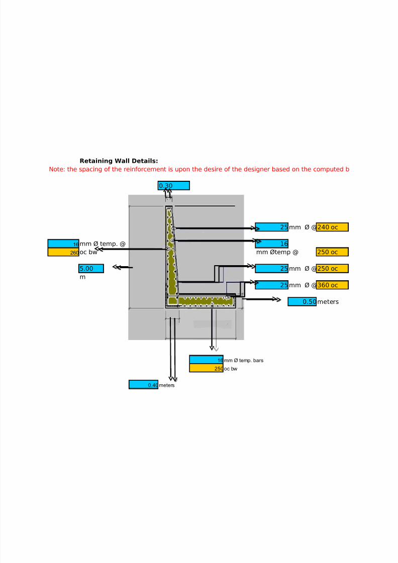
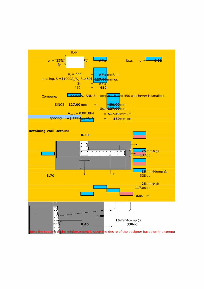
Retaining Wall Details:
Note: the spacing of the reinforcement is upon the desire of the designer based on the computed b
0.30
25mm Ø @240 oc
16 mm Ø temp. @ 16
260 oc bw mm Øtemp @ 250 oc
5.00 25 mm Ø @250 oc
m
25mm Ø @360 oc
0.50meters
16 mm Ø temp. bars
250oc bw
0.40meters

5/13/2018 25690825 Retaining Walls - slidepdf.com
http://slidepdf.com/reader/full/25690825-retaining-walls 14/70
CARMEL B. SABADO CE-162 PROF. GERONIDES P. ANCOG
BSCE-5 2nd Excel Program ###*note:the boxes in yellow should be inputed by the designer,while blue ones are computed by the program.=)
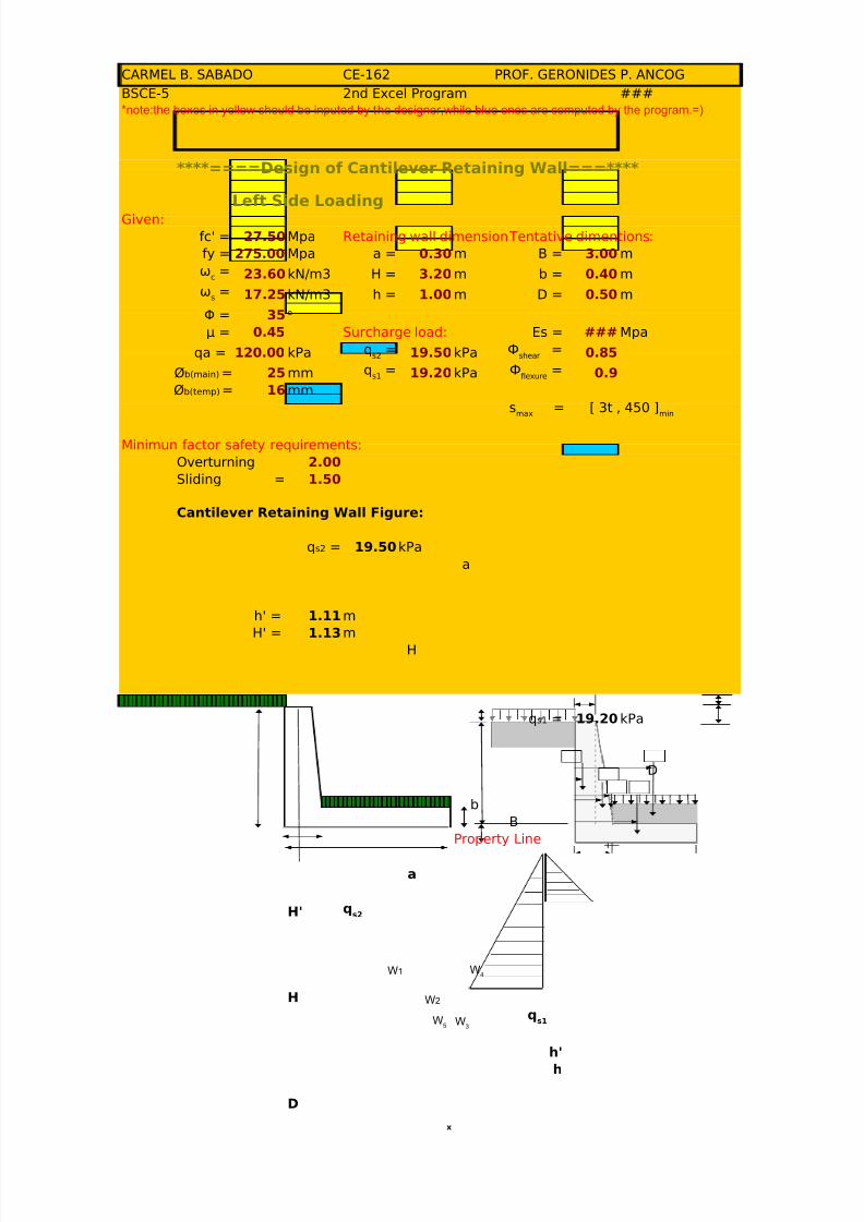
****====Design of Cantilever Retaining Wall===****
Left Side LoadingGiven:
fc' = 27.50Mpa Retaining wall dimensions: Tentative dimentions:
fy = 275.00 Mpa a = 0.30m B = 3.00m
23.60kN/m3 H = 3.20m b = 0.40m
17.25kN/m3 h = 1.00m D = 0.50m
Φ = 35
μ = 0.45 Surcharge load: Es = 200000 Mpaqa = 120.00 kPa 19.50kPa 0.85
25 mm 19.20kPa 0.9
16 mm
Minimun factor safety requirements:
Overturning 2.00
Sliding = 1.50
Cantilever Retaining Wall Figure:
19.50kPa
a
h' = 1.11m
H' = 1.13m
H
19.20kPa
D
b
B
Property Line
a
H'
ωc=
ωs=
o
qs2
= Фshear
=
Øb(main) = qs1
= Фflexure
=
Øb(temp) =s
max= [ 3t , 450 ]
min
qs2 =
qs1 =
qs2
5/13/2018 25690825 Retaining Walls - slidepdf.com
http://slidepdf.com/reader/full/25690825-retaining-walls 15/70
H
h'
h
D
b
B
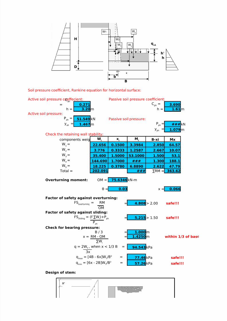
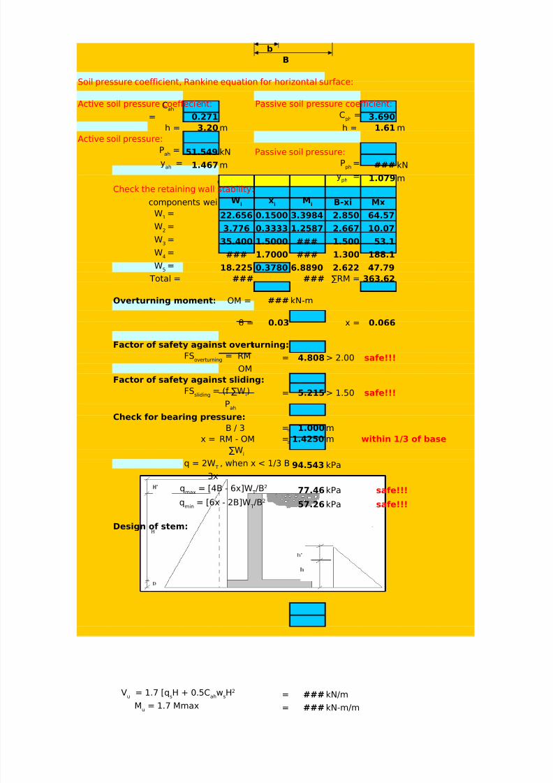
Soil pressure coefficient, Rankine equation for horizontal surface:
Active soil pressure coeffecient: Passive soil pressure coefficient:
0.271 3.690
h = 3.20m h = 1.61m
Active soil pressure:
51.549 kN Passive soil pressure:
1.467m ###kN
1.079m
Check the retaining wall stability:
components weig B-xi Mx
22.656 0.1500 3.3984 2.850 64.573.776 0.3333 1.2587 2.667 10.07
35.400 1.5000 53.1000 1.500 53.1
144.690 1.7000 ### 1.300 188.1
18.225 0.3780 6.8890 2.622 47.79
Total = 202.091 ### ∑RM = 363.62
Overturning moment: OM = 75.6346kN-m
θ = 0.03 x = 0.066
Factor of safety against overturning:
= 4.808> 2.00 safe!!!
OM
Factor of safety against sliding:
= 5.215> 1.50 safe!!!
Check for bearing pressure:
B / 3 = 1.000m
x = RM - OM = 1.4250m within 1/3 of bas
94.543kPa
3x
77.46kPa safe!!!
57.26kPa safe!!!
Design of stem:
qs1
x
Cah
= Cph
=
Pah
=
yah
= Pph
=
yph
=
Wi
xi
Mi
W1 =W
2=
W3=
W4=
W5=
FSoverturning
= RM
FSsliding
= (f ∑Wi)+P
ph
Pah
∑Wi
q = 2W T
, when x < 1/3 B =
qmax
= [4B - 6x]W T/B2 =
qmin
= [6x - 2B]W T/B2 =
W3
W4
W5
W2
W1
5/13/2018 25690825 Retaining Walls - slidepdf.com
http://slidepdf.com/reader/full/25690825-retaining-walls 16/70
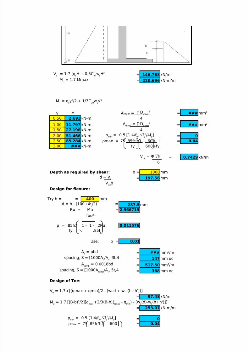
= 146.768kN/m
= 220.696kN-m/m
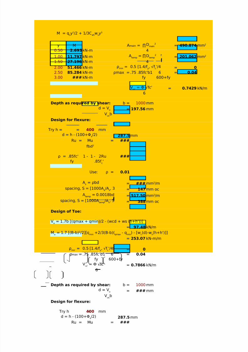
y M = ###
0.50 2.693kN-m 4
1.00 11.797 kN-m = ###
1.50 27.196 kN-m 4
2.00 51.466 kN-m = 0
2.50 85.284 kN-m ρmax = = 0.04
3.00 ### kN-m fy 600+fy
= 0.7429kN/m
6
Depth as required by shear: b = 1000mm
= 197.56mm
Design for flexure:
Try h = = 400 mm
287.5mm
Ru = Mu = 2.966719
ρ = 0.011576
Use: ρ = 0.01
= ###
= 147mm oc
= 517.50
= 388mm oc
Design of Toe:
= 97.48kN/m
= 253.07kN-m/m
= 0
= 0.04
Vu
= 1.7 [qsH + 0.5C
ahw
sH2
Mu
= 1.7 Mmax
M = qsy2/2 + 1/3C
ahw
sy3
Amain = ∏ Dmain
2mm2
Atemp
= ∏Dtemp
2mm2
ρmin
=
0.5 [1.4/f y, √f
c'/4f
y]
.75 .85fc'b1 600
Vuc
= Ф √f
d = Vu
Vuc
b
d = h - (100+Φs/2) =
fbd2
.85fc' 1 - 1 - 2Ru
fy .85f c'
As= ρbd mm2/m
spacing, S = [1000Ao/A
s, 3t,4
Atemp
= 0.0018bd mm2/m
spacing, S = [1000Atemp
/As, 5t,4
Vu
= 1.7b [(qmax + qmin)/2 - (wcd + ws (h+h'))]
Mu
= 1.7 [(B-b)2/2][qmin
+2/3(B-b)(qmax
- qmin
) - [wc(d)-w
s(h+h')]]
ρmin
=
0.5 [1.4/f y, √f
c'/4f
y]
ρmax = .75 .85fc'b1 600
5/13/2018 25690825 Retaining Walls - slidepdf.com
http://slidepdf.com/reader/full/25690825-retaining-walls 17/70
fy 600+fy
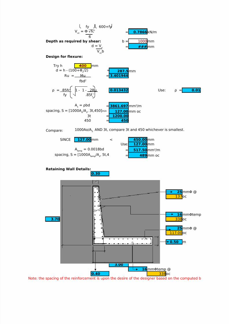
= 0.7866kN/m
6
Depth as required by shear: b = 1000mm
= ###mm
Design for flexure:
Try h =400 mm
287.5mm
Ru = Mu = 3.401944
ρ = 0.013432 Use: ρ = 0.01
= 3861.697
127.00 mm oc
3t = 1200.00
450 = 450
Compare:
SINCE 127.00 mm < 450.00mm
Use: 127.00mm
= 517.50
= 489mm oc
Retaining Wall Details:
0.30
25 mmΦ @
137oc
16 mmΦtemp
3.70 338oc
25 mmΦ @
117.00oc
0.50 m
3.00
16mmΦtemp @
0.40 338oc
Note: the spacing of the reinforcement is upon the desire of the designer based on the computed b
Vuc
= Ф √fc'
d = Vu
Vuc
b
d = h - (100+Φs/2) =
fbd2
.85fc' 1 - 1 - 2Ru
fy .85f c'
As= ρbd mm2/m
spacing, S = [1000Ao/A
s, 3t,450]min
1000Ao/AS
AND 3t, compare 3t and 450 whichever is smallest.
Atemp
= 0.0018bd mm2/m
spacing, S = [1000Atemp
/As, 5t,4

5/13/2018 25690825 Retaining Walls - slidepdf.com
http://slidepdf.com/reader/full/25690825-retaining-walls 18/70
CARMEL B. SABADO CE-162 PROF. GERONIDES P. ANCOG
BSCE-5 2nd Excel Program ###*note:the boxes in yellow should be inputed by the designer,while blue ones are computed by the program.=)
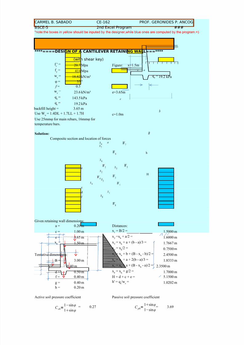
****====DESIGN OF A CANTILEVER RETAINING WALL===****
(with shear key)20.7 Mpa Figure: x=1.5m
414 Mpa
18.82 kN/m³ 19.2 kPa
φ = 35 °
0.5
23.6 kN/m³ e=3.65m
143.5 kPa
19.2 kPa
backfill height = 3.65 m
c=1.0m
Use 25mmφ for main rebars, 16mmφ for
temperature bars.
Solution:
Composite section and location of forces
e
c
d
f
Given retaining wall dimensions:
f c' =
f y
=
ws= q
a=
f =
wc=
qa
=
qs=
Use Wu = 1.4DL + 1.7LL + 1.7H
h
H
a x
e
b
B
W 7
W 6
W 5
W 4
W 3
W 2
W 1
W 8
a xh
x7
x6
x5
x2
x4
x3
x1
x8
5/13/2018 25690825 Retaining Walls - slidepdf.com
http://slidepdf.com/reader/full/25690825-retaining-walls 19/70
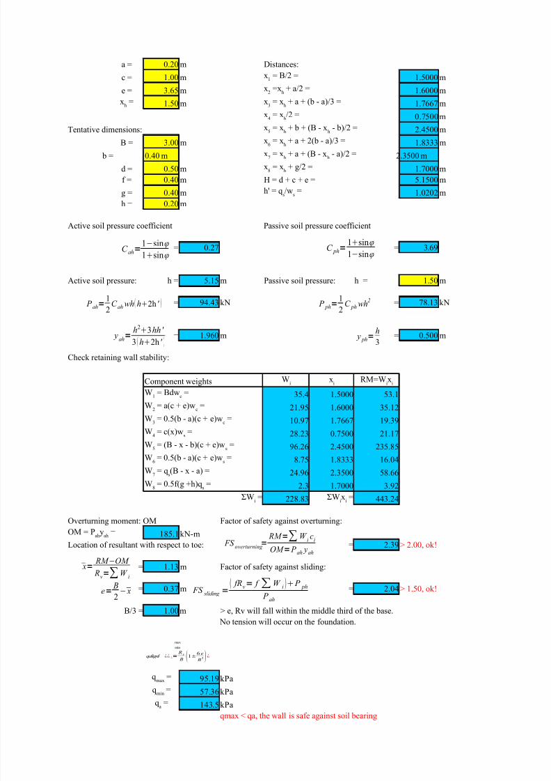
a = 0.20 m Distances:
c = 1.00 m 1.5000 m
e = 3.65 m 1.6000 m
1.50 m 1.7667 m
0.7500mTentative dimensions: 2.4500 m
B = 3.00 m 1.8333 m
b = 0.40 m 2.3500 m
d = 0.50 m 1.7000 m
f = 0.40 m H = d + c + e = 5.1500 m
g = 0.40 m 1.0202 m
h = 0.20 m
Active soil pressure coefficient Passive soil pressure coefficient
= 0.27 = 3.69
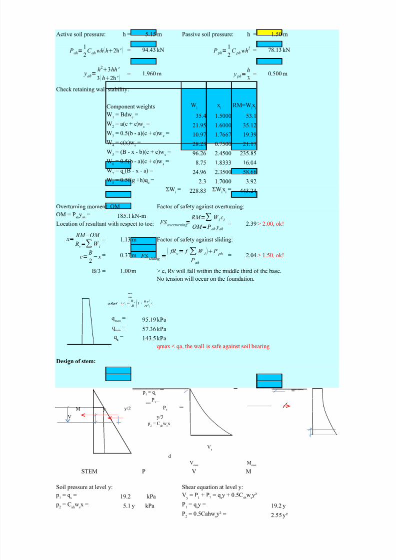
Active soil pressure: h = 5.15 m Passive soil pressure: h = 1.50 m
= 94.43 kN = 78.13 kN
= 1.960 m = 0.500 m
Check retaining wall stability:
Component weights
35.4 1.5000 53.1
21.95 1.6000 35.12
10.97 1.7667 19.39
28.23 0.7500 21.17
96.26 2.4500 235.85
8.75 1.8333 16.04
24.96 2.3500 58.662.3 1.7000 3.92
228.83 443.24
Overturning moment: OM Factor of safety against overturning:
185.1kN-m
Location of resultant with respect to toe: = 2.39 > 2.00, ok!
= 1.13 m Factor of safety against sliding:
= 0.37 m = 2.04 > 1.50, ok!
B/3 = 1.00m > e, Rv will fall within the middle third of the base.
No tension will occur on the foundation.
95.19kPa
57.36kPa
143.5 kPa
qmax < qa, the wall is safe against soil bearing
x1
= B/2 =
x2
=xh
+ a/2 =
xh
= x3
= xh
+ a + (b - a)/3 =
x4 = xh/2 =x
5= x
h+ b + (B - x
h- b)/2 =
x6
= xh
+ a + 2(b - a)/3 =
x7
= xh
+ a + (B - xh
- a)/2 =
x8
= xh
+ g/2 =
h' = qs/w
s=
Wi
xi
RM=Wix
i
W1
= Bdwc=
W2
= a(c + e)wc=
W3
= 0.5(b - a)(c + e)wc
=
W4
= c(x)ws=
W5
= (B - x - b)(c + e)ws=
W6
= 0.5(b - a)(c + e)ws=
W7 = qs(B - x - a) =W
8= 0.5f(g +h)q
s=
ΣWi= ΣW
ix
i=
OM = Pah
yah
=
qmax
=
qmin
=
qa
=
C ah=1−sinφ
1sinφC ph=
1sinφ
1−sinφ
P ah=1
2C ah wh h2h ' P ph=
1
2C ph wh
2
yah=
h23hh '
3 h2h ' y ph=
h
3
x=RM −OM
Rv=∑W
i
e=
B
2− x
FS overturning
= RM =∑W
ic
i
OM = P ah yah
FS sliding =
fRv= f ∑W i P ph P ah
max
min
qalignl ¿¿ ¿= R
v
B 1±6 e
B2 ¿

5/13/2018 25690825 Retaining Walls - slidepdf.com
http://slidepdf.com/reader/full/25690825-retaining-walls 20/70
Design of stem:
M y y/2
V y/3
d
STEM P V M
Soil pressure at level y: Shear equation at level y:
19.2 kPa
5.1 y kPa 19.2 y
2.55 y²
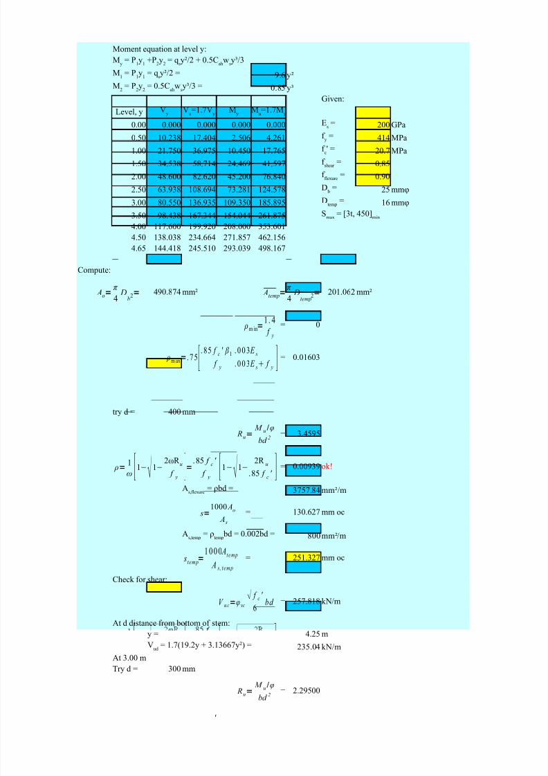
Moment equation at level y:
9.6 y²
0.85 y³
Given:
Level, y
0.00 0.000 0.000 0.000 0.000 200 GPa
0.50 10.238 17.404 2.506 4.261 414 MPa
1.00 21.750 36.975 10.450 17.765 20.7 MPa
1.50 34.538 58.714 24.469 41.597 0.85
2.00 48.600 82.620 45.200 76.840 0.90
2.50 63.938 108.694 73.281 124.578 25 mmφ
3.00 80.550 136.935 109.350 185.895 16 mmφ
3.50 98.438 167.344 154.044 261.875
4.00 117.600 199.920 208.000 353.601
4.50 138.038 234.664 271.857 462.156
4.65 144.418 245.510 293.039 498.167
Compute:
490.874 mm² 201.062 mm²
= 0
= 0.01603
try d = 400 mm
= 3.4595
p1
= qs
P1
P2
p2
= Cah
wsx
Ve
Vmax
Mmax
p1
= qs= V
y= P
1+ P
2= q
sy + 0.5C
ahw
sy²
p2
= Cah
wsx = P
1= q
sy =
P2
= 0.5Cahwsy² =
My
= P1y
1+P
2y
2= q
sy²/2 + 0.5C
ahw
sy³/3
M1
= P1y
1= q
sy²/2 =
M2
= P2y
2= 0.5C
ahw
sy³/3 =
Vy
Vu=1.7V
yM
yM
u=1.7M
y
Es=
f y
=
f c' =
f shear
=
f flexure
=
D b
=
Dtemp
=
Smax = [3t, 450]min
Ao=π
4D
b2= Atemp=
π
4D
temp2=
ρm in=1 . 4
f y
ρmax=.75[.85 f c ' β
1
f y
.003 E s
.003 E s f y ]
Ru=
M u/φ
bd 2
'
5/13/2018 25690825 Retaining Walls - slidepdf.com
http://slidepdf.com/reader/full/25690825-retaining-walls 21/70
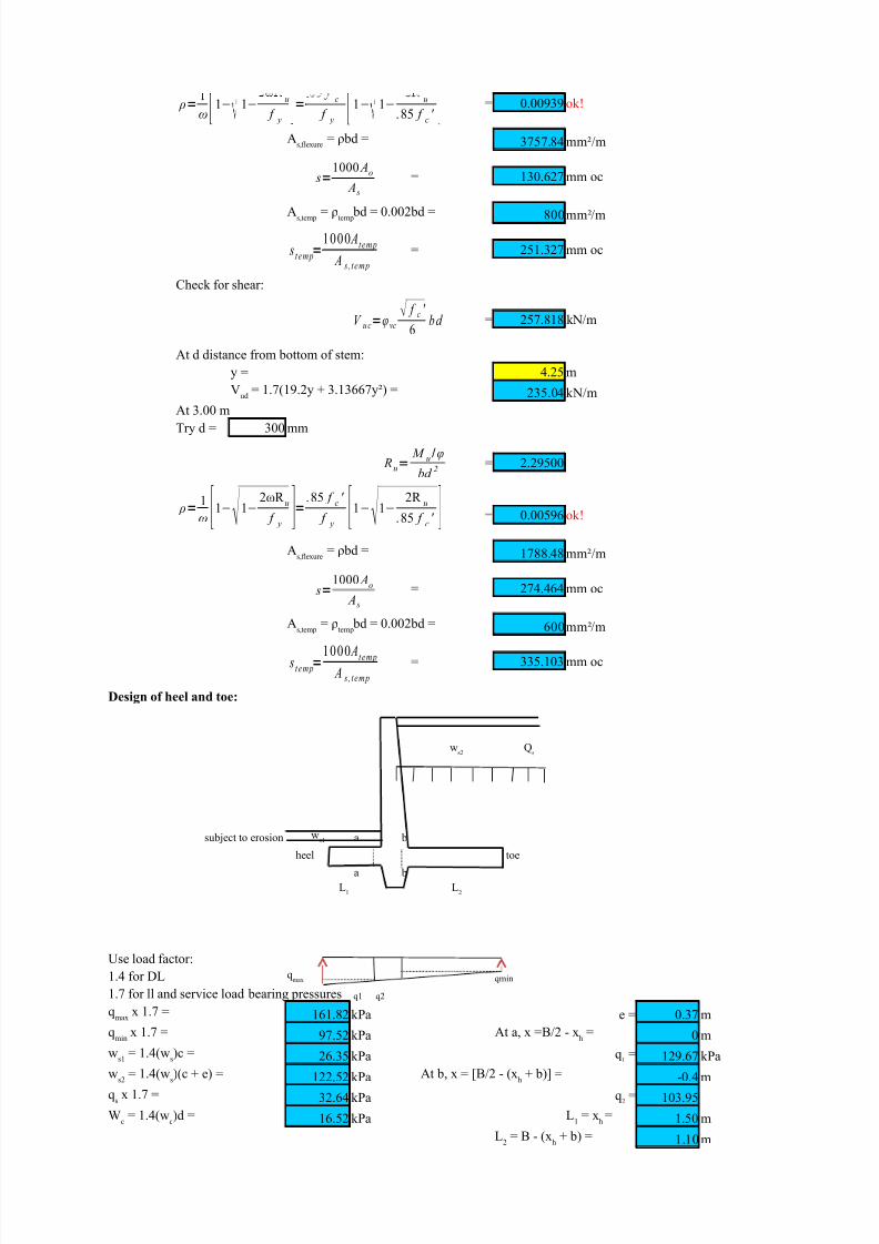
= 0.00939 ok!
3757.84 mm²/m
= 130.627 mm oc
800mm²/m
= 251.327 mm oc
Check for shear:
= 257.818 kN/m
At d distance from bottom of stem:
y = 4.25 m235.04 kN/m
At 3.00 m
Try d = 300 mm
= 2.29500
= 0.00596 ok!
1788.48 mm²/m
= 274.464 mm oc
600mm²/m
= 335.103 mm oc
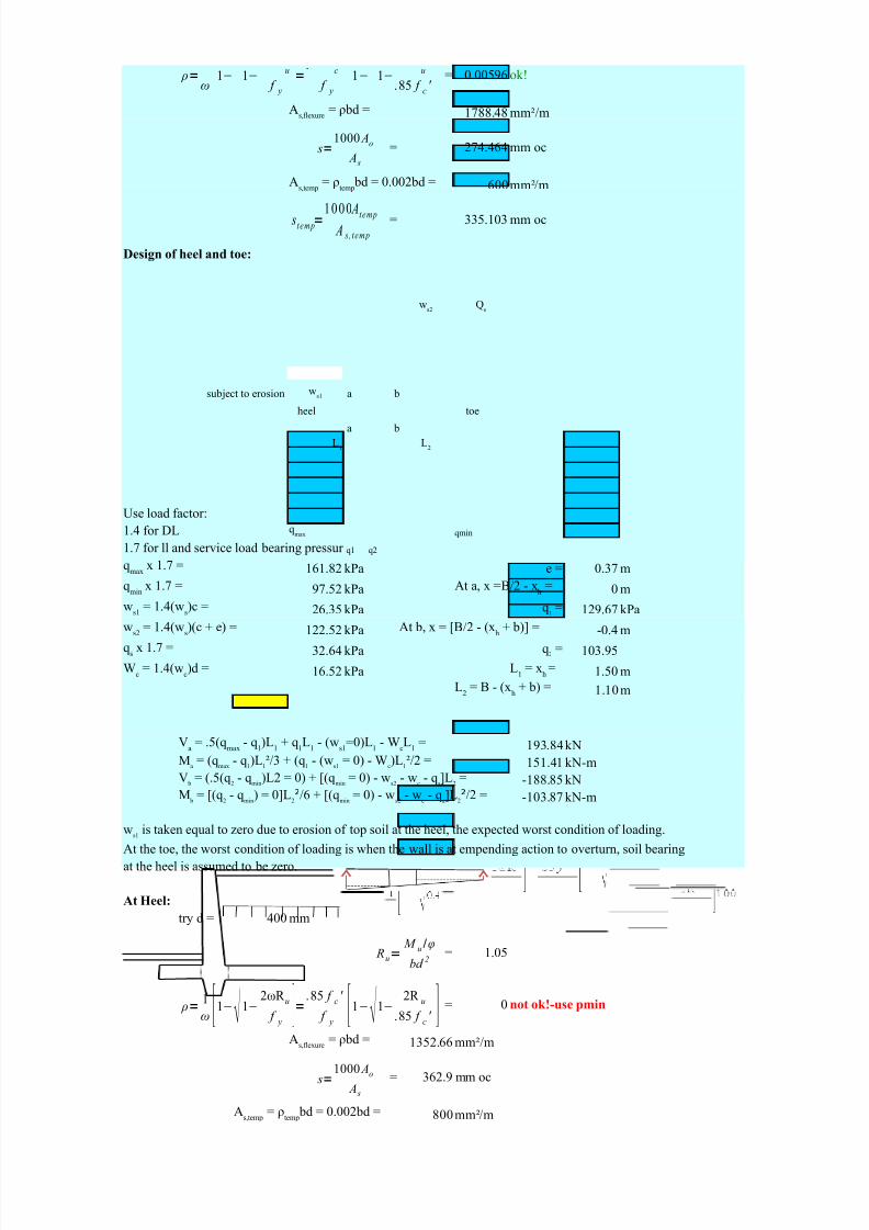
Design of heel and toe:
subject to erosion a b
heel toe
a b
Use load factor:
1.4 for DL qmin
1.7 for ll and service load bearing pressures q1 q2
161.82 kPa e = 0.37 m
97.52 kPa 0 m
26.35 kPa 129.67 kPa
122.52 kPa -0.4 m
32.64 kPa 103.95
16.52 kPa 1.50 m
1.10 m
As,flexure
= ρbd =
As,temp
= ρtemp
bd = 0.002bd =
Vud
= 1.7(19.2y + 3.13667y²) =
As,flexure
= ρbd =
As,temp
= ρtemp
bd = 0.002bd =
ws2
Qs
ws1
L1
L2
qmax
qmax
x 1.7 =
qmin
x 1.7 = At a, x =B/2 - xh
=
ws1
= 1.4(ws)c = q
1=
ws2
= 1.4(ws)(c + e) = At b, x = [B/2 - (x
h+ b)] =
qsx 1.7 = q
2=
Wc
= 1.4(wc)d = L
1= x
h=
L2 = B - (xh + b) =
ρ=ω
1− 1−u
f y
=. c
f y
1− 1−u
.85 f c
'
s=1000 Ao
A s
s temp=1000 Atemp
A s , temp
V u c=φvc
f c '
6b d
Ru=M u /φ
bd 2
ρ=1
ω [1− 1−2ωR u
f y
]= .85 f c '
f y
[1− 1−2R u
.85 f c
' ]
s=1000 Ao
A s
s temp=1000 Atemp
A s , temp
5/13/2018 25690825 Retaining Walls - slidepdf.com
http://slidepdf.com/reader/full/25690825-retaining-walls 22/70
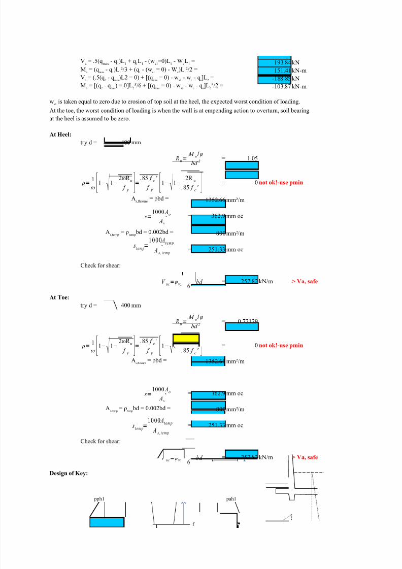
193.84kN
151.41 kN-m
-188.85 kN
-103.87 kN-m
At the toe, the worst condition of loading is when the wall is at empending action to overturn, soil bearing
at the heel is assumed to be zero.
At Heel:
try d = 400 mm
= 1.05
= 0 not ok!-use pmin
1352.66 mm²/m
= 362.9 mm oc
800mm²/m
= 251.33 mm oc
Check for shear:
= 257.82 kN/m > Va, safe
At Toe:
try d = 400 mm
= 0.72129
= 0 not ok!-use pmin
1352.66 mm²/m
= 362.9 mm oc
800mm²/m
= 251.33 mm oc
Check for shear:
= 257.82 kN/m > Va, safe
Design of Key:
pph1 pah1
f
Va= .5(q
max- q
1)L
1+ q
1L
1- (w
s1=0)L
1- W
cL
1=
Ma= (q
max- q
1)L
1²/3 + (q
1- (w
s1= 0) - W
c)L
1²/2 =
V b
= (.5(q2- q
min)L2 = 0) + [(q
min= 0) - w
s2- w
c- q
s]L
2=
M b = [(q2 - qmin) = 0]L2²/6 + [(qmin = 0) - ws2 - wc - qa]L2²/2 =
ws1
is taken equal to zero due to erosion of top soil at the heel, the expected worst condition of loading.
As,flexure
= ρbd =
As,temp
= ρtemp
bd = 0.002bd =
As,flexure
= ρbd =
As,temp
= ρtemp
bd = 0.002bd =
Ru=
M u/φ
bd 2
ρ=1
ω [1− 1− 2ωR u
f y ]= .85 f c '
f y [1− 1− 2R u
.85 f c ' ]
s=1000 Ao
A s
stemp=1000 Atemp
A s , temp
V u c=φvc
f c '
6b d
Ru=
M u/φ
bd 2
ρ=1
ω [1−
1−
2ωR u
f y ]=
.85 f c
'
f y [
1−
1−
2R u
.85 f c
' ]
s=1000 Ao
A s
s temp=1000 Atemp
A s , temp
V u c=φvc
f c '
6b d
5/13/2018 25690825 Retaining Walls - slidepdf.com
http://slidepdf.com/reader/full/25690825-retaining-walls 23/70
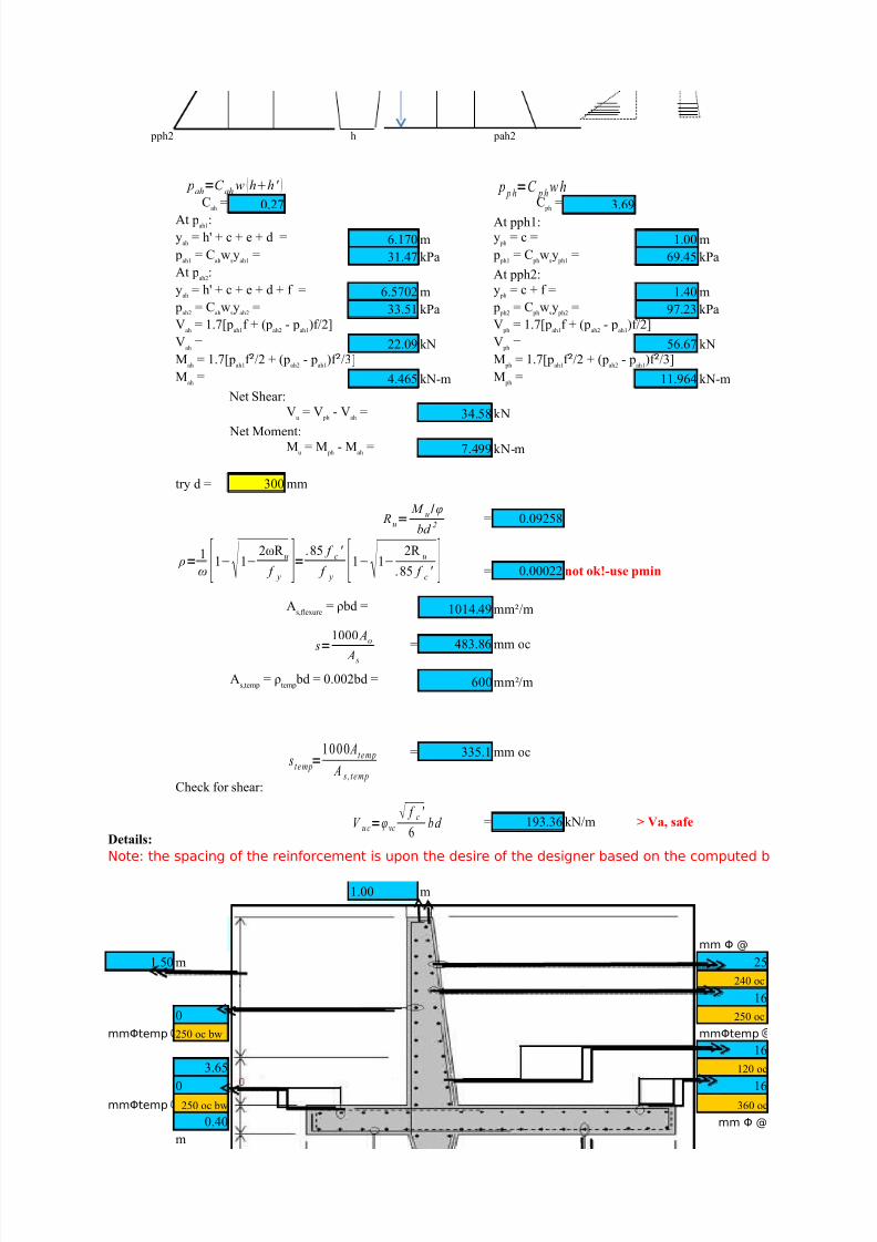
pph2 h pah2
0.27 3.69
At pph1:
6.170 m 1.00 m
31.47 kPa 69.45 kPa
At pph2:
6.5702 m 1.40 m
33.51 kPa 97.23 kPa
22.09 kN 56.67 kN
4.465 kN-m 11.964 kN-m Net Shear:
34.58 kN
Net Moment:
7.499 kN-m
try d = 300 mm
= 0.09258
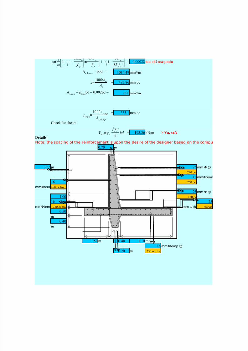
= 0.00022 not ok!-use pmin
1014.49 mm²/m
= 483.86 mm oc
600mm²/m
= 335.1 mm oc
Check for shear:
= 193.36 kN/m > Va, safe
Details:
Note: the spacing of the reinforcement is upon the desire of the designer based on the computed b
1.00 m
mm Φ @
1.50 m 25
240 oc
16
0 250 oc
mmΦtemp 250 oc bw mmΦtemp
16
3.65 120 oc
0 16
mmΦtemp 250 oc bw 360 oc
0.40 mm Φ @
m
Cah
= C ph
=
At pah1
:
yah
= h' + c + e + d = y ph
= c =
pah1
= Cahw
sy
ah1= p
ph1= C
phw
sy
ph1=
At pah2
:
yah
= h' + c + e + d + f = y ph
= c + f =
pah2
= Cahw
sy
ah2= p
ph2= C
phw
sy
ph2=
Vah
= 1.7[pah1
f + (pah2
- pah1
)f/2] V ph
= 1.7[pah1
f + (pah2
- pah1
)f/2]
Vah
= V ph
=
Mah
= 1.7[pah1
f ²/2 + (pah2
- pah1
)f ²/3] M ph
= 1.7[pah1
f ²/2 + (pah2
- pah1
)f ²/3]
Mah = M ph =
Vu= V
ph- V
ah=
Mu= M
ph- M
ah=
As,flexure
= ρbd =
As,temp
= ρtemp
bd = 0.002bd =
pah=C ah w hh' p p h=C p h w h
Ru=
M u/φ
bd 2
ρ=
1
ω
[1−
1−
2ωR u
f y ]=
.85 f c '
f y [
1−
1−
2R u
.85 f c
'
] s=
1000 Ao
A s
stemp=1000 Atemp
A s , temp
V u c=φvc
f c '
6b d
5/13/2018 25690825 Retaining Walls - slidepdf.com
http://slidepdf.com/reader/full/25690825-retaining-walls 24/70
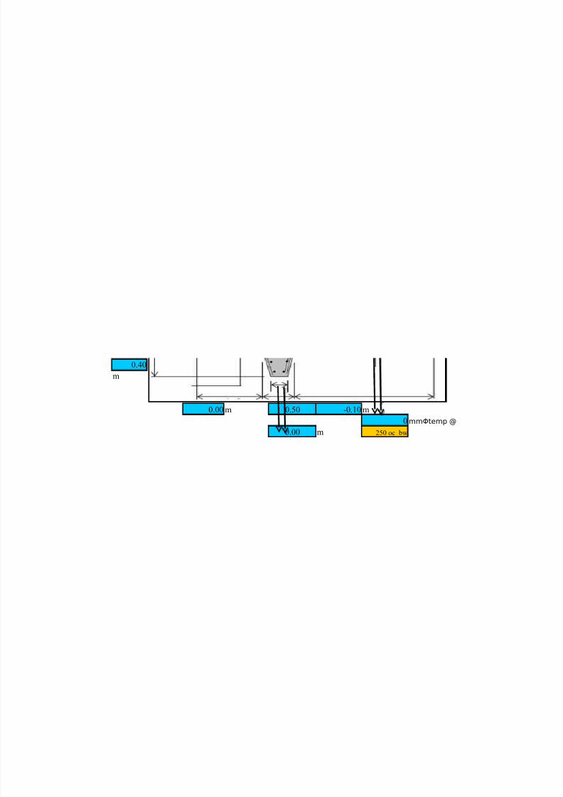
0.40
m
0.00 m 0.50 -0.10 m
0 mmΦtemp @
0.00 m 250 oc bw

5/13/2018 25690825 Retaining Walls - slidepdf.com
http://slidepdf.com/reader/full/25690825-retaining-walls 25/70

5/13/2018 25690825 Retaining Walls - slidepdf.com
http://slidepdf.com/reader/full/25690825-retaining-walls 26/70

5/13/2018 25690825 Retaining Walls - slidepdf.com
http://slidepdf.com/reader/full/25690825-retaining-walls 27/70

5/13/2018 25690825 Retaining Walls - slidepdf.com
http://slidepdf.com/reader/full/25690825-retaining-walls 28/70

5/13/2018 25690825 Retaining Walls - slidepdf.com
http://slidepdf.com/reader/full/25690825-retaining-walls 29/70

5/13/2018 25690825 Retaining Walls - slidepdf.com
http://slidepdf.com/reader/full/25690825-retaining-walls 30/70
5/13/2018 25690825 Retaining Walls - slidepdf.com
http://slidepdf.com/reader/full/25690825-retaining-walls 31/70
ar spacing above.

5/13/2018 25690825 Retaining Walls - slidepdf.com
http://slidepdf.com/reader/full/25690825-retaining-walls 32/70

5/13/2018 25690825 Retaining Walls - slidepdf.com
http://slidepdf.com/reader/full/25690825-retaining-walls 33/70

5/13/2018 25690825 Retaining Walls - slidepdf.com
http://slidepdf.com/reader/full/25690825-retaining-walls 34/70

5/13/2018 25690825 Retaining Walls - slidepdf.com
http://slidepdf.com/reader/full/25690825-retaining-walls 35/70
@
ar spacing above.

5/13/2018 25690825 Retaining Walls - slidepdf.com
http://slidepdf.com/reader/full/25690825-retaining-walls 36/70

5/13/2018 25690825 Retaining Walls - slidepdf.com
http://slidepdf.com/reader/full/25690825-retaining-walls 37/70

5/13/2018 25690825 Retaining Walls - slidepdf.com
http://slidepdf.com/reader/full/25690825-retaining-walls 38/70

5/13/2018 25690825 Retaining Walls - slidepdf.com
http://slidepdf.com/reader/full/25690825-retaining-walls 39/70

5/13/2018 25690825 Retaining Walls - slidepdf.com
http://slidepdf.com/reader/full/25690825-retaining-walls 40/70

5/13/2018 25690825 Retaining Walls - slidepdf.com
http://slidepdf.com/reader/full/25690825-retaining-walls 41/70
ar spacing above.

5/13/2018 25690825 Retaining Walls - slidepdf.com
http://slidepdf.com/reader/full/25690825-retaining-walls 42/70
5/13/2018 25690825 Retaining Walls - slidepdf.com
http://slidepdf.com/reader/full/25690825-retaining-walls 43/70
CARMEL B. SABADO CE-162 PROF. GERONIDES P. ANCOG
BSCE-5 2nd Excel Program 18-Aug-09*note:the boxes in yellow should be inputed by the designer,while blue ones are computed by the program.=)
****====Design of Cantilever Retaining Wall===****
Right Side LoadingGiven:
fc' = 20.70 Mpa Retaining wall dimensions:fy = 414.00 Mpa a = 0.30 m
18.82 kN/m3 c = 4.50 m
Φ = 40
μ = 0.50 Tentative dimentions:
23.60 kN/m3 B = 3.20 m
143.50 kPa b = 0.40 m
19.30 kPa d = 0.50 m backfill height = 3.65 m
Øb(main) 25 mm Use Wu = 1.4DL + 1.7LL + 1.7HØb(temp) 16 mm
aEs = 200000 Mpa
0.85 qs = 19.30 kPa
0.9
c
h' = 1.026 m
Cantilever Retaining Wall Figure:
d
bProperty Line
a
h'
c h
d
BSoil pressure coefficient, Rankine equation for horizontal surface:
Active soil pressure coeffecient: 0.217443
Active soil pressure: h = 5.00 m
2 72.137 kN
ωs =o
ωc
=
qa
=
qs
=
Øshear
=
Øflexure
=
smax
= [ 3t , 450 ]min
Pah
y ah
b
Cah
=
Pah = 1 Cahωh(h+2h') =
W1
C1
W2
C2
W3
W4
W5
C3
C4
C5
W6
C6
5/13/2018 25690825 Retaining Walls - slidepdf.com
http://slidepdf.com/reader/full/25690825-retaining-walls 44/70
3(h + 2h') 1.9091 m
Check the retaining wall stability:
components weights
37.760 1.6000 60.4160
31.860 0.1500 4.7790
5.310 0.3333 1.7700
237.132 1.8000 426.8376
4.235 0.3333 1.4115
55.97 1.75 97.9475
372.267 ∑RM = 593.1616
Overturning moment: OM = 137.7138kN-m
Factor of safety against overturning:
= 4.307 > 2.00 safe!!!!
OM
Factor of safety against sliding:
= 2.580 > 1.50 safe!!!!
Check for bearing pressure: 143.50 kPa
Location of resultant with respect to toe:x = RM - OM = 1.2234 m
e = B - x = 0.376554 m2
B / 3 = 1.07 m
The middle third of the base where No tension will occur on the foundation.
q = 142.001 kPa
90.666 kPa
< safe againts soil bearing.
Design of stem:
Soil pressure at y: Moment equation at level y:
= 19.30 kPa
4.09 y kPa = 9.65
0.68
Shear equation at level y:
At level y = 4.50 m
y ah
= h2 + 3hh' =
W i
ci
RM = W ic
i
W 1 =
W 2=
W 3=
W 4=
W 5=
W 6=
∑W i=
FSoverturning
= RM
FSsliding
= (f ∑W i)
Pah
qa
=
∑W i
∑Wi 1 + 6e qmax
=
B B2
qmin =
Since qmax qa, wall is
p1
= qs
My = p1 y
1+ p
2 y
2= q
s y 2/2 + 0.5c
ah w
s y 3/3
p2
= cah w
s y = M
1= q
s y 2/2 y 2
M2
= 0.5cah w
s y 3/3 = y 3
V y = p1 + p2 = qs y + 0.5cah w s y 2
Ve
p1=q
s
P1 P
2
p2= C
ahw
sy
y/2yM
V
dV
maxM
max
Stem P MV
5/13/2018 25690825 Retaining Walls - slidepdf.com
http://slidepdf.com/reader/full/25690825-retaining-walls 45/70
= 19.30 y 218.08 kN
2.05 437.86 kN-m
490.874 = 0
4 ρmax = = 0.02
201.062 fy 600+fy
4
Try d = 400 mm ; b = 1000 mmRu = Mu = 3.040685
ρ = 0.00812
Use: ρ = 0.01
= 3248.172
= 151.1231mm ccAs
800
= 251.3274mm cc
Check for shear: = 257.8178kN/m6
At d distance from the bottom of stem:4.10 m
192.99 kN/m < Vuc, safe!!!!
At y = 3.00 mTry d = 300 mm
Ru = Mu = 2.209270
ρ = 0.005722
Use: ρ = 0.01
= 1716.459
= 285.9805 mm ccAs
600
= 335.1032 mm cc
Design of Base:
19.30
5.00
0.50
p1
= qs y V
u=
p2
= 0.5cah w
s y 2 = y 2 M
u=
Ao = ∏ D b
2 = mm2 ρmin
=
1.4 / f y
.75 .85fc'b1 600
A temp
= ∏ Dtemp
2 = mm2
fbd2
.85fc' 1 - 1 - 2Ru =
fy .85f c'
A s,flexure = ρbd mm2/ms = 1000A
o
A s,temp
= ρbd =0.002bd = mm2/m
stemp
= 1000 A temp
A s
V uc
= Ø √fc' bd
y d
=
V ud
=
fbd2
.85fc' 1 - 1 - 2Ru =
fy .85f c'
A s,flexure
= ρbd mm2/m
s = 1000A o
A s,temp
= ρbd =0.002bd = mm2/m
stemp
= 1000 A temp
A s
qs=
5/13/2018 25690825 Retaining Walls - slidepdf.com
http://slidepdf.com/reader/full/25690825-retaining-walls 46/70
Note: The expected worst condition of loading, the passive earth pressure of soil is generally neglected due to erosion of top soil, and the soil bearing at the toe is neglected due to
the empending action to overturn.
Use: 1.4 for DL1.7 for LL and service load bearing pressure
241.401 kPa = -470.11 kN
= 154.132 kPa -658.15 kN-m
118.566 kPa
= 32.810 kPa
16.520 kPae = 0.377 m
2.800 m
Try d = 400 mm b = 1000 mm
Ru = Mu = 4.570502 = 5216.20
= 94.11 mm ccAs
ρ = 0.013041 800.00
= 251.33 mm cc
Use: ρ = 0.01
Check for shear: = 257.8178 kN/m > V, safe!!!!
6
Retaining Wall Details:
Note: the spacing of the reinforcement is upon the desire of the designer based on the comput
0.30
25mm Ø @240 oc
16 mm Ø temp. @ 16
260 oc bw mm Øtemp @ 250 oc
5.00 25 250 oc
m
25mm Ø @360 oc
0.50meters
16 mm Ø temp. bars
250oc bw
0.40meters
qmax
x 1.7 = V = (-W s-W
c-q
s)L
qmin
x 1.7 M = (-W s-W
c-q
s)L2/2 =
W s
= 1.4ωsc =
qs
x 1.7
W c
= 1.4ωcd =
L = B - b) =
A s,flexure
= ρbd mm2/m
fbd2 s = 1000A o
.85fc' 1 - 1 - 2Ru = A s,temp
= ρbd =0.002bd = mm2/m
fy .85f c' s
temp= 1000 A
temp
A s
V uc
= Ø √fc' bd
qmin
qmax

5/13/2018 25690825 Retaining Walls - slidepdf.com
http://slidepdf.com/reader/full/25690825-retaining-walls 47/70

5/13/2018 25690825 Retaining Walls - slidepdf.com
http://slidepdf.com/reader/full/25690825-retaining-walls 48/70

5/13/2018 25690825 Retaining Walls - slidepdf.com
http://slidepdf.com/reader/full/25690825-retaining-walls 49/70
5/13/2018 25690825 Retaining Walls - slidepdf.com
http://slidepdf.com/reader/full/25690825-retaining-walls 50/70
d bar spacing above.
5/13/2018 25690825 Retaining Walls - slidepdf.com
http://slidepdf.com/reader/full/25690825-retaining-walls 51/70
CARMEL B. SABADO CE-162 PROF. GERONIDES P. ANCOG
BSCE-5 2nd Excel Program ###*note:the boxes in yellow should be inputed by the designer,while blue ones are computed by the program.=)
****====Design of Cantilever Retaining Wall===****
Left Side LoadingGiven:
fc' = 27.50Mpa Retaining wall dimensionTentative dimentions:
fy = 275.00 Mpa a = 0.30m B = 3.00 m
23.60kN/m3 H = 3.20m b = 0.40 m
17.25kN/m3 h = 1.00m D = 0.50 m
Φ = 35
μ = 0.45 Surcharge load: Es = ### Mpa
qa = 120.00 kPa 19.50kPa 0.85
25mm 19.20kPa 0.916mm
Minimun factor safety requirements:
Overturning 2.00
Sliding = 1.50
Cantilever Retaining Wall Figure:
19.50kPa
a
h' = 1.11m
H' = 1.13m
H
19.20kPa
D
b
B
Property Line
a
H'
H
h'
h
D
ωc=
ωs=
o
qs2
= Фshear
=
Øb(main) = qs1 = Фflexure =Øb(temp) =
smax
= [ 3t , 450 ]min
qs2 =
qs1 =
qs2
qs1
x
W3
W4
W5
W2
W1
5/13/2018 25690825 Retaining Walls - slidepdf.com
http://slidepdf.com/reader/full/25690825-retaining-walls 52/70
b
B
Soil pressure coefficient, Rankine equation for horizontal surface:
Active soil pressure coeffecient: Passive soil pressure coefficient:
0.271 3.690h = 3.20m h = 1.61 m
Active soil pressure:
51.549 kN Passive soil pressure:
1.467m ### kN
1.079m
Check the retaining wall stability:
components wei B-xi Mx
22.656 0.1500 3.3984 2.850 64.57
3.776 0.3333 1.2587 2.667 10.07
35.400 1.5000 ### 1.500 53.1
### 1.7000 ### 1.300 188.1
18.225 0.3780 6.8890 2.622 47.79
Total = ### ### ∑RM = 363.62
Overturning moment: OM = ### kN-m
θ = 0.03 x = 0.066
Factor of safety against overturning:
= 4.808> 2.00 safe!!!OM
Factor of safety against sliding:
= 5.215> 1.50 safe!!!
Check for bearing pressure:
B / 3 = 1.000m
x = RM - OM = 1.4250 m within 1/3 of base
94.543 kPa
3x
77.46kPa safe!!!
57.26kPa safe!!!
Design of stem:
= ###kN/m
= ###kN-m/m
Cah
= Cph =
Pah
=
yah
= Pph
=
yph
=
Wi
xi
Mi
W1=
W2=
W3 =
W4=
W5=
FSoverturning = RM
FSsliding
= (f ∑Wi)
Pah
∑Wi
q = 2W T
, when x < 1/3 B
qmax
= [4B - 6x]W T/B2
qmin
= [6x - 2B]W T/B2
Vu
= 1.7 [qsH + 0.5C
ahw
sH2
Mu
= 1.7 Mmax
5/13/2018 25690825 Retaining Walls - slidepdf.com
http://slidepdf.com/reader/full/25690825-retaining-walls 53/70
y M = 490.874
0.50 2.693kN-m 4
1.00 11.797 kN-m = 201.062
1.50 27.196 kN-m 4
2.00 51.466 kN-m = 0
2.50 85.284 kN-m ρmax = = 0.04
3.00 ### kN-m fy 600+fy
= 0.7429 kN/m
6
Depth as required by shear: b = 1000 mm
= 197.56 mm
Design for flexure:
Try h = = 400 mm
287.5mm
Ru = Mu = ###
ρ = ###
Use: ρ = 0.01
= ###
= 147mm oc
= 517.50
= 388mm oc
Design of Toe:
= 97.48kN/m
= 253.07 kN-m/m
= 0
= 0.04
fy 600+fy
= 0.7866 kN/m6
Depth as required by shear: b = 1000 mm
= ###mm
Design for flexure:
Try h =400 mm
287.5mm
Ru = Mu = ###
M = qsy2/2 + 1/3C
ahw
sy3
Amain = ∏ Dmain
2mm2
Atemp
= ∏Dtemp
2mm2
ρmin
=
0.5 [1.4/f y, √f
c'/4
.75 .85fc'b1 6
Vuc
= Ф √fc'
d = Vu
Vuc
b
d = h - (100+Φs/2)
fbd2
.85fc' 1 - 1 - 2Ru
fy .85f c'
As= ρbd mm2/m
spacing, S = [1000Ao/A
s, 3
Atemp
= 0.0018bd mm2/m
spacing, S = [1000Atemp
/As, 5
Vu
= 1.7b [(qmax + qmin)/2 - (wcd + ws (h+h'))]
Mu
= 1.7 [(B-b)2/2][qmin
+2/3(B-b)(qmax
- qmin
) - [wc(d)-w
s(h+h')]]
ρmin
=
0.5 [1.4/f y, √f
c'/4f
ρmax =.75 .85fc'b1 6
Vuc
= Ф √fc'
d = Vu
Vuc
b
d = h - (100+Φs/2)
5/13/2018 25690825 Retaining Walls - slidepdf.com
http://slidepdf.com/reader/full/25690825-retaining-walls 54/70
ρ = ### Use: ρ = 0.01
= ###
127.00 mm oc
3t = ###
450 = 450
Compare:
SINCE 127.00 mm < 450.00 mm
Use: 127.00 mm
= 517.50
= 489mm oc
Retaining Wall Details:0.30
25 mmΦ @
137 oc
16 mmΦtemp @
3.70 338 oc
25 mmΦ @
117.00oc
0.50 m
3.00
16mmΦtemp @0.40 338oc
Note: the spacing of the reinforcement is upon the desire of the designer based on the compu
fbd2
.85fc' 1 - 1 - 2Ru
fy .85f c'
As= ρbd mm2/m
spacing, S = [1000Ao/A
s, 3t,450]m
1000Ao/AS
AND 3t, compare 3t and 450 whichever is smallest.
Atemp
= 0.0018bd mm2/m
spacing, S = [1000Atemp
/As, 5

5/13/2018 25690825 Retaining Walls - slidepdf.com
http://slidepdf.com/reader/full/25690825-retaining-walls 55/70

5/13/2018 25690825 Retaining Walls - slidepdf.com
http://slidepdf.com/reader/full/25690825-retaining-walls 56/70

5/13/2018 25690825 Retaining Walls - slidepdf.com
http://slidepdf.com/reader/full/25690825-retaining-walls 57/70
5/13/2018 25690825 Retaining Walls - slidepdf.com
http://slidepdf.com/reader/full/25690825-retaining-walls 58/70
ed bar spacing above.
5/13/2018 25690825 Retaining Walls - slidepdf.com
http://slidepdf.com/reader/full/25690825-retaining-walls 59/70
CARMEL B. SABADO CE-162 PROF. GERONIDES P. ANCOG
BSCE-5 2nd Excel Program ###*note:the boxes in yellow should be inputed by the designer,while blue ones are computed by the program.=)
****====DESIGN OF A CANTILEVER RETAINING WALL===****
(with shear key)
20.7 Mpa Figure: x=1.5m
414Mpa
18.82 kN/m³ 19.2 kPa
φ = 35 °
0.5
23.6 kN/m³ e=3.65m
143.5 kPa
19.2 kPa backfill height = 3.65 m
c=1.0m
Use 25mmφ for main rebars, 16mmφ for
temperature bars.
Solution:
Composite section and location of forces
e
c
d
f
Given retaining wall dimensions:
a = 0.20 m Distances:
c = 1.00 m 1.5000 m
e = 3.65 m 1.6000 m
1.50 m 1.7667 m
0.7500m
Tentative dimensions: 2.4500 m
B = 3.00 m 1.8333 m b = 0.40 m 2.3500 m
d = 0.50 m 1.7000 m
f = 0.40 m H = d + c + e = 5.1500 m
g = 0.40 m 1.0202 m
h = 0.20 m
Active soil pressure coefficient Passive soil pressure coefficient
= 0.27 = 3.69
f c' =
f y
=
ws= q
a=
f =
wc=
qa=
qs =
Use Wu
= 1.4DL + 1.7LL + 1.7H
x1
= B/2 =
x2
=xh
+ a/2 =
xh
= x3
= xh
+ a + (b - a)/3 =
x4
= xh/2 =
x5
= xh
+ b + (B - xh
- b)/2 =
x6
= xh
+ a + 2(b - a)/3 =
x7
= xh
+ a + (B - xh
- a)/2 =
x8
= xh
+ g/2 =
h' = qs/w
s=
h
H
a x
e
b
B
C ah=1−sinφ
1sinφC ph=
1sinφ
1−sinφ
W 7
W 6
W 5
W 4
W 3
W 2
W 1
W 8
a xh
x7
x6
x5
x2
x4
x3
x1
x8
5/13/2018 25690825 Retaining Walls - slidepdf.com
http://slidepdf.com/reader/full/25690825-retaining-walls 60/70
Active soil pressure: h = 5.15 m Passive soil pressure: h = 1.50 m
= 94.43 kN = 78.13 kN
= 1.960 m = 0.500 m
Check retaining wall stability:
Component weights
35.4 1.5000 53.1
21.95 1.6000 35.12
10.97 1.7667 19.39
28.23 0.7500 21.17
96.26 2.4500 235.85
8.75 1.8333 16.04
24.96 2.3500 58.66
2.3 1.7000 3.92
228.83 443.24
Overturning moment: OM Factor of safety against overturning:
185.1kN-m
Location of resultant with respect to toe: = 2.39 > 2.00, ok!
= 1.13 m Factor of safety against sliding:
= 0.37 m = 2.04 > 1.50, ok!
B/3 = 1.00m > e, Rv will fall within the middle third of the base.
No tension will occur on the foundation.
95.19 kPa
57.36 kPa
143.5 kPaqmax < qa, the wall is safe against soil bearing
Design of stem:
M y y/2
V y/3
d
STEM P V M
Soil pressure at level y: Shear equation at level y:
19.2 kPa
5.1 y kPa 19.2 y
2.55y²
Wi
xi
RM=Wix
i
W1
= Bdwc
=
W2
= a(c + e)wc
=
W3
= 0.5(b - a)(c + e)wc=
W4
= c(x)ws=
W5
= (B - x - b)(c + e)ws=
W6
= 0.5(b - a)(c + e)ws=
W7 = qs(B - x - a) =
W8
= 0.5f(g +h)qs=
ΣWi= ΣW
ix
i=
OM = Pah
yah
=
qmax
=
qmin
=
qa =
p1
= qs
P1
P2
p2 = Cahwsx
Ve
Vmax
Mmax
p1
= qs= V
y= P
1+ P
2= q
sy + 0.5C
ahw
sy²
p2
= Cah
wsx = P
1= q
sy =
P2
= 0.5Cahwsy² =
P ah=1
2C ah wh h2h ' P ph=
1
2C ph wh
2
yah=
h23hh '
3 h2h ' y ph=
h
3
x=RM −OM
Rv=∑W
i
e= B2− x
FS overturning = RM =∑W i ci
OM = P ah yah
FS sliding = fR
v= f ∑W
i P
ph P ah
max
min
qalignl ¿¿¿= R
v
B 1±6 e
B2 ¿
5/13/2018 25690825 Retaining Walls - slidepdf.com
http://slidepdf.com/reader/full/25690825-retaining-walls 61/70
Moment equation at level y:
9.6 y²
0.85 y³
Given:
Level, y
0.00 0.000 0.000 0.000 0.000 200 GPa
0.50 10.238 17.404 2.506 4.261 414 MPa
1.00 21.750 36.975 10.450 17.765 20.7 MPa
1.50 34.538 58.714 24.469 41.597 0.85
2.00 48.600 82.620 45.200 76.840 0.90
2.50 63.938 108.694 73.281 124.578 25 mmφ
3.00 80.550 136.935 109.350 185.895 16 mmφ
3.50 98.438 167.344 154.044 261.875
4.00 117.600 199.920 208.000 353.601
4.50 138.038 234.664 271.857 462.156
4.65 144.418 245.510 293.039 498.167
Compute:
490.874 mm² 201.062 mm²
= 0
= 0.01603
try d = 400 mm
= 3.4595
= 0.00939 ok!
3757.84 mm²/m
= 130.627 mm oc
800mm²/m
= 251.327 mm oc
Check for shear:
= 257.818 kN/m
At d distance from bottom of stem:
y = 4.25 m
235.04 kN/m
At 3.00 m
Try d = 300 mm
= 2.29500
My
= P1y
1+P
2y
2= q
sy²/2 + 0.5C
ahw
sy³/3
M1
= P1y
1= q
sy²/2 =
M2
= P2y
2= 0.5C
ahw
sy³/3 =
Vy
Vu=1.7V
yM
yM
u=1.7M
y
Es=
f y
=
f c' =
f shear
=
f flexure
=
D b
=
Dtemp
=
Smax
= [3t, 450]min
As,flexure
= ρbd =
As,temp
= ρtemp
bd = 0.002bd =
Vud
= 1.7(19.2y + 3.13667y²) =
Ao=π
4D
b2= Atemp=
π
4D
temp2=
ρm in=1. 4
f y
ρmax=. 75
[. 85 f c ' β 1
f y
. 003 E s
. 003 E s f y ]
Ru=M u /φ
bd 2
ρ=
1
ω
[1−
1−
2ωR u
f y
]=
.85 f c '
f y
[1−
1−
2R u
.85 f c '
] s=
1000 Ao
A s
stemp=1000 Atemp
A s , temp
V u c=φvc
f c '
6bd
Ru=M u /φ
bd 2
'
5/13/2018 25690825 Retaining Walls - slidepdf.com
http://slidepdf.com/reader/full/25690825-retaining-walls 62/70
= 0.00596 ok!
1788.48 mm²/m
= 274.464 mm oc
600mm²/m
= 335.103 mm oc
Design of heel and toe:
subject to erosion a b
heel toe
a b
Use load factor:
1.4 for DL qmin
1.7 for ll and service load bearing pressur q1 q2
161.82 kPa e = 0.37 m
97.52 kPa 0 m
26.35 kPa 129.67 kPa
122.52 kPa -0.4 m
32.64 kPa 103.95
16.52 kPa 1.50 m
1.10m
193.84kN151.41 kN-m
-188.85 kN
-103.87 kN-m
At the toe, the worst condition of loading is when the wall is at empending action to overturn, soil bearing
at the heel is assumed to be zero.
At Heel:
try d = 400 mm
= 1.05
= 0 not ok!-use pmin
1352.66 mm²/m
= 362.9 mm oc
800mm²/m
As,flexure
= ρbd =
As,temp = ρtemp bd = 0.002bd =
ws2
Qs
ws1
L1
L2
qmax
qmax
x 1.7 =
qmin
x 1.7 = At a, x =B/2 - xh
=
ws1
= 1.4(ws)c = q
1=
ws2
= 1.4(ws)(c + e) = At b, x = [B/2 - (x
h+ b)] =
qsx 1.7 = q
2=
Wc= 1.4(w
c)d = L
1= x
h=
L2
= B - (xh
+ b) =
Va = .5(qmax - q1)L1 + q1L1 - (ws1=0)L1 - WcL1 =M
a= (q
max- q
1)L
1²/3 + (q
1- (w
s1= 0) - W
c)L
1²/2 =
V b
= (.5(q2- q
min)L2 = 0) + [(q
min= 0) - w
s2- w
c- q
s]L
2=
M b
= [(q2- q
min) = 0]L
2²/6 + [(q
min= 0) - w
s2- w
c- q
a]L
2²/2 =
ws1
is taken equal to zero due to erosion of top soil at the heel, the expected worst condition of loading.
As,flexure
= ρbd =
As,temp
= ρtemp
bd = 0.002bd =
ρ=ω
1− 1−u
f y=. c
f y1− 1−
u
.85 f c '
s=1000 A
o
A s
stemp=1000 Atemp
A s , temp
Ru=M u /φ
bd 2
ρ=1
ω [1− 1−2ωR u
f y
]=.85 f c '
f y
[1− 1−2R u
.85 f c
' ]
s=1000 Ao
A s

5/13/2018 25690825 Retaining Walls - slidepdf.com
http://slidepdf.com/reader/full/25690825-retaining-walls 63/70
= 251.33 mm oc
Check for shear:
= 257.82 kN/m > Va, safe
At Toe:try d = 400 mm
= 0.72129
= 0 not ok!-use pmin
1352.66 mm²/m
= 362.9 mm oc
800mm²/m
= 251.33 mm oc
Check for shear:
= 257.82 kN/m > Va, safe
Design of Key:
pph1 pah1
f
pph2 h pah2
0.27 3.69
At pph1:
6.170 m 1.00 m
31.47 kPa 69.45 kPa
At pph2:
6.5702 m 1.40 m
33.51 kPa 97.23 kPa
22.09 kN 56.67 kN
4.465 kN-m 11.964 kN-m
Net Shear:
34.58 kN
Net Moment:
7.499kN-m
try d = 300 mm
= 0.09258
As,flexure
= ρbd =
As,temp
= ρtemp
bd = 0.002bd =
Cah
= C ph
=
At pah1
:
yah
= h' + c + e + d = y ph
= c =
pah1
= Cahw
sy
ah1= p
ph1= C
phw
sy
ph1=
At pah2
:
yah
= h' + c + e + d + f = y ph
= c + f =
pah2
= Cahw
sy
ah2= p
ph2= C
phw
sy
ph2=
Vah
= 1.7[pah1
f + (pah2
- pah1
)f/2] V ph
= 1.7[pah1
f + (pah2
- pah1
)f/2]
Vah
= V ph
=
Mah = 1.7[pah1f ²/2 + (pah2 - pah1)f ²/3] M ph = 1.7[pah1f ²/2 + (pah2 - pah1)f ²/3]
Mah
= M ph
=
Vu= V
ph- V
ah=
Mu= M
ph- M
ah=
stemp=temp
A s , temp
V u c=φvc
f c '
6bd
Ru=M u /φ
bd 2
ρ=1
ω [1− 1−2ωR u
f y ]=.85 f c '
f y [1− 1−2R u
.85 f c ' ]
s=1000 Ao
A s
stemp=1000 Atemp
A s , temp
V u c=φvc
f c '
6bd
pah=C
ahw hh' p p h=C p h w h
Ru=
M u /φ
bd 2
'
5/13/2018 25690825 Retaining Walls - slidepdf.com
http://slidepdf.com/reader/full/25690825-retaining-walls 64/70
= 0.00022 not ok!-use pmin
1014.49 mm²/m
= 483.86 mm oc
600mm²/m
= 335.1 mm oc
Check for shear:
= 193.36 kN/m > Va, safe
Details:
Note: the spacing of the reinforcement is upon the desire of the designer based on the compu
0.20 m
3.65 m 25 mm Φ @
240 oc
16 mmΦtem
16 250 oc
mmΦtem 250 oc bw
25 mm Φ @
1.00 120 oc
16 25
mmΦtem 250 oc bw mm Φ @ 360 oc
0.50m
0.40
m
1.50 m 0.40 1.10 m
16 mmΦtemp @
0.20 m 250 oc bw
As,flexure
= ρbd =
As,temp
= ρtemp
bd = 0.002bd =
ρ=ω
1− 1−u
f y
=. c
f y
1− 1−u
.85 f c
'
s=1000 A
o
A s
stemp=
1000 Atemp
A s , temp
V u c=φvc
f c '
6bd

5/13/2018 25690825 Retaining Walls - slidepdf.com
http://slidepdf.com/reader/full/25690825-retaining-walls 65/70

5/13/2018 25690825 Retaining Walls - slidepdf.com
http://slidepdf.com/reader/full/25690825-retaining-walls 66/70

5/13/2018 25690825 Retaining Walls - slidepdf.com
http://slidepdf.com/reader/full/25690825-retaining-walls 67/70

5/13/2018 25690825 Retaining Walls - slidepdf.com
http://slidepdf.com/reader/full/25690825-retaining-walls 68/70

5/13/2018 25690825 Retaining Walls - slidepdf.com
http://slidepdf.com/reader/full/25690825-retaining-walls 69/70
5/13/2018 25690825 Retaining Walls - slidepdf.com
http://slidepdf.com/reader/full/25690825-retaining-walls 70/70
ted bar spacing above.
@