Embed Size (px)
DESCRIPTION
:)
Citation preview
Novel conventional and phased array angle beam probes with the same DGS
accuracy as flat circular straight beam probes
Wolf Kleinert, York Oberdörfer
GE Sensing & Inspection Technologies GmbH; Hürth, Germany Phone +49 2233 601300; e-mail: [email protected], [email protected]
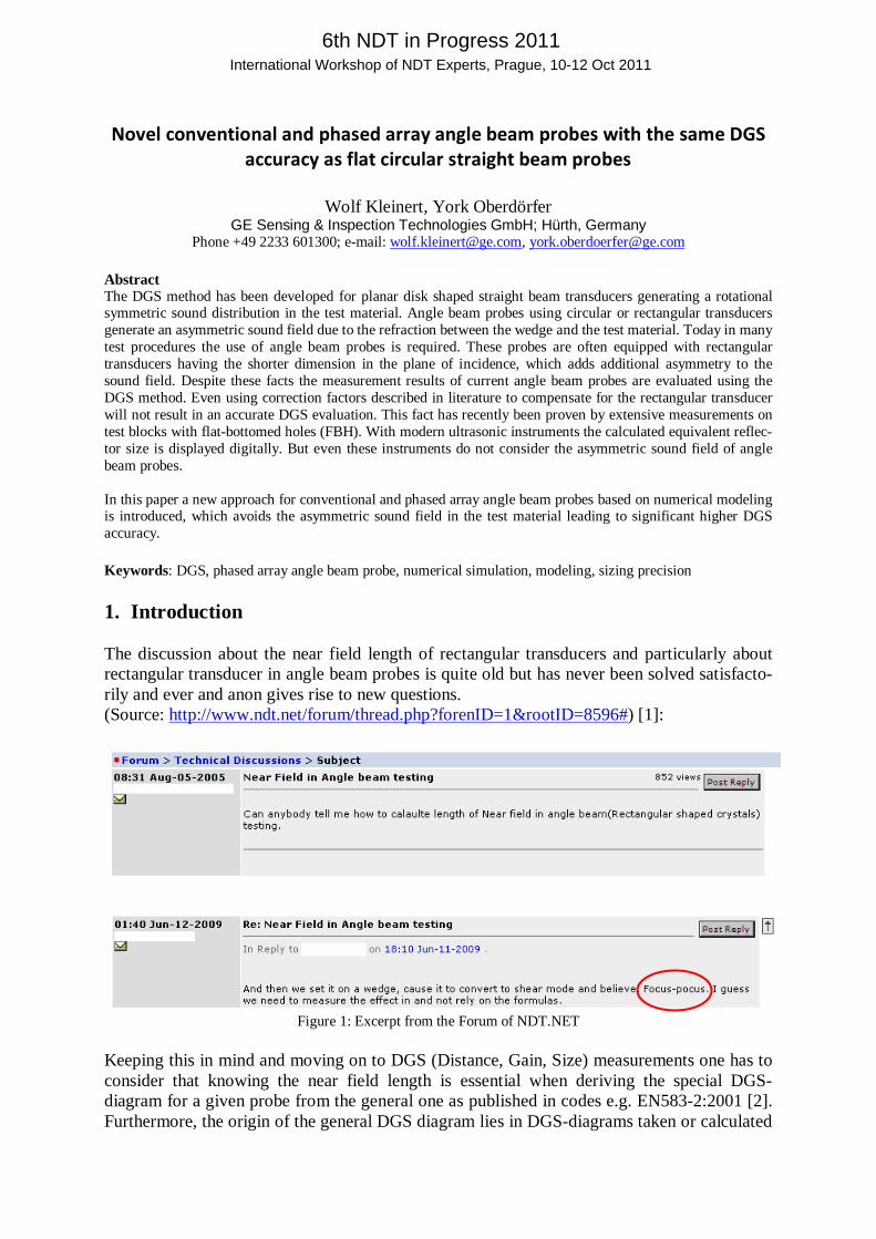
Abstract The DGS method has been developed for planar disk shaped straight beam transducers generating a rotational symmetric sound distribution in the test material. Angle beam probes using circular or rectangular transducers generate an asymmetric sound field due to the refraction between the wedge and the test material. Today in many test procedures the use of angle beam probes is required. These probes are often equipped with rectangular transducers having the shorter dimension in the plane of incidence, which adds additional asymmetry to the sound field. Despite these facts the measurement results of current angle beam probes are evaluated using the DGS method. Even using correction factors described in literature to compensate for the rectangular transducer will not result in an accurate DGS evaluation. This fact has recently been proven by extensive measurements on test blocks with flat-bottomed holes (FBH). With modern ultrasonic instruments the calculated equivalent reflec-tor size is displayed digitally. But even these instruments do not consider the asymmetric sound field of angle beam probes. In this paper a new approach for conventional and phased array angle beam probes based on numerical modeling is introduced, which avoids the asymmetric sound field in the test material leading to significant higher DGS accuracy. Keywords: DGS, phased array angle beam probe, numerical simulation, modeling, sizing precision 1. Introduction The discussion about the near field length of rectangular transducers and particularly about rectangular transducer in angle beam probes is quite old but has never been solved satisfacto-rily and ever and anon gives rise to new questions. (Source: http://www.ndt.net/forum/thread.php?forenID=1&rootID=8596#) [1]:
Figure 1: Excerpt from the Forum of NDT.NET
Keeping this in mind and moving on to DGS (Distance, Gain, Size) measurements one has to consider that knowing the near field length is essential when deriving the special DGS-diagram for a given probe from the general one as published in codes e.g. EN583-2:2001 [2]. Furthermore, the origin of the general DGS diagram lies in DGS-diagrams taken or calculated
6th NDT in Progress 2011 International Workshop of NDT Experts, Prague, 10-12 Oct 2011
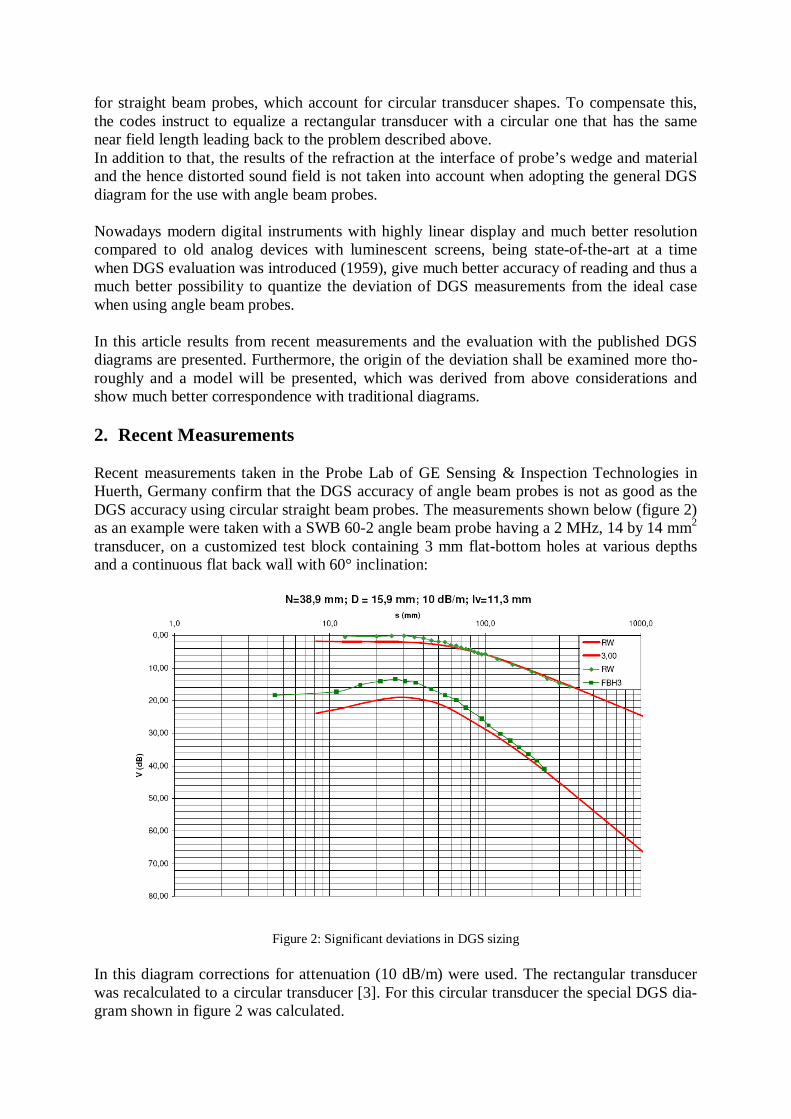
for straight beam probes, which account for circular transducer shapes. To compensate this, the codes instruct to equalize a rectangular transducer with a circular one that has the same near field length leading back to the problem described above. In addition to that, the results of the refraction at the interface of probe’s wedge and material and the hence distorted sound field is not taken into account when adopting the general DGS diagram for the use with angle beam probes. Nowadays modern digital instruments with highly linear display and much better resolution compared to old analog devices with luminescent screens, being state-of-the-art at a time when DGS evaluation was introduced (1959), give much better accuracy of reading and thus a much better possibility to quantize the deviation of DGS measurements from the ideal case when using angle beam probes. In this article results from recent measurements and the evaluation with the published DGS diagrams are presented. Furthermore, the origin of the deviation shall be examined more tho-roughly and a model will be presented, which was derived from above considerations and show much better correspondence with traditional diagrams. 2. Recent Measurements Recent measurements taken in the Probe Lab of GE Sensing & Inspection Technologies in Huerth, Germany confirm that the DGS accuracy of angle beam probes is not as good as the DGS accuracy using circular straight beam probes. The measurements shown below (figure 2) as an example were taken with a SWB 60-2 angle beam probe having a 2 MHz, 14 by 14 mm2 transducer, on a customized test block containing 3 mm flat-bottom holes at various depths and a continuous flat back wall with 60° inclination:
Figure 2: Significant deviations in DGS sizing
In this diagram corrections for attenuation (10 dB/m) were used. The rectangular transducer was recalculated to a circular transducer [3]. For this circular transducer the special DGS dia-gram shown in figure 2 was calculated.
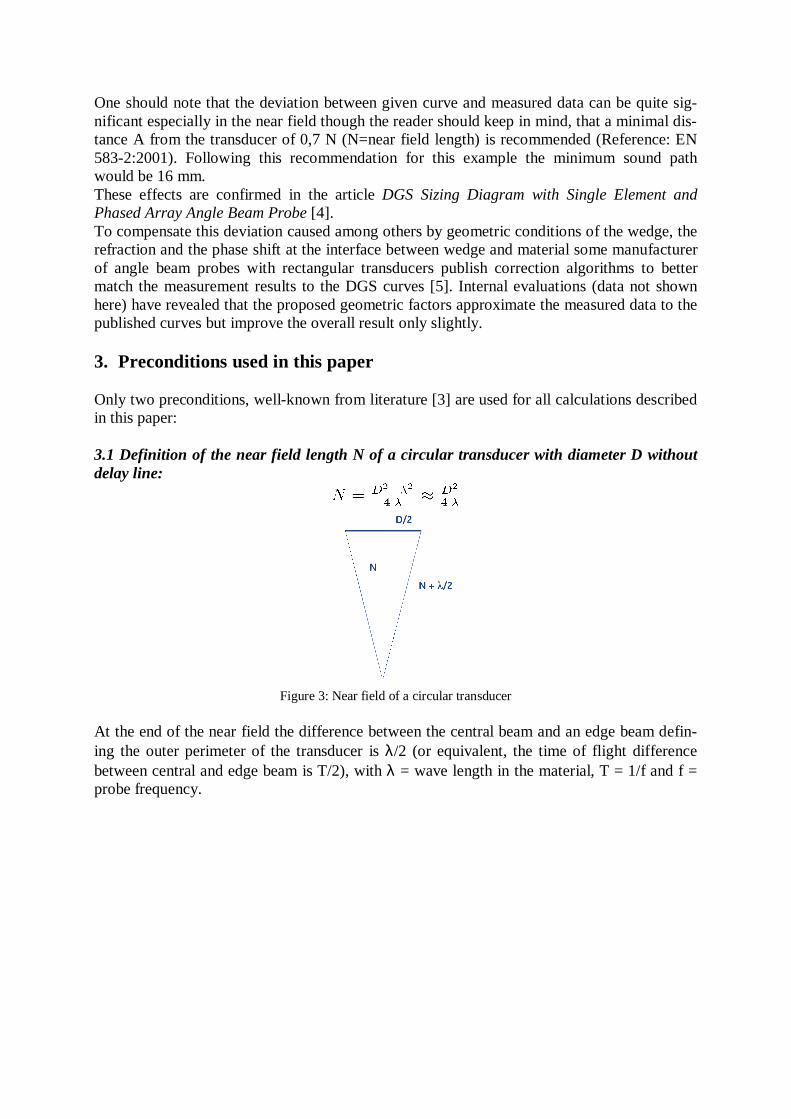
One should note that the deviation between given curve and measured data can be quite sig-nificant especially in the near field though the reader should keep in mind, that a minimal dis-tance A from the transducer of 0,7 N (N=near field length) is recommended (Reference: EN 583-2:2001). Following this recommendation for this example the minimum sound path would be 16 mm. These effects are confirmed in the article DGS Sizing Diagram with Single Element and Phased Array Angle Beam Probe [4]. To compensate this deviation caused among others by geometric conditions of the wedge, the refraction and the phase shift at the interface between wedge and material some manufacturer of angle beam probes with rectangular transducers publish correction algorithms to better match the measurement results to the DGS curves [5]. Internal evaluations (data not shown here) have revealed that the proposed geometric factors approximate the measured data to the published curves but improve the overall result only slightly. 3. Preconditions used in this paper Only two preconditions, well-known from literature [3] are used for all calculations described in this paper: 3.1 Definition of the near field length N of a circular transducer with diameter D without delay line:
Figure 3: Near field of a circular transducer
At the end of the near field the difference between the central beam and an edge beam defin-ing the outer perimeter of the transducer is λ/2 (or equivalent, the time of flight difference between central and edge beam is T/2), with λ = wave length in the material, T = 1/f and f = probe frequency.
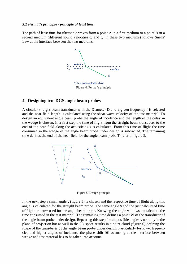
3.2 Fermat’s principle / principle of least time The path of least time for ultrasonic waves from a point A in a first medium to a point B in a second medium (different sound velocities cv and cm in these two mediums) follows Snells' Law at the interface between the two mediums.
Figure 4: Fermat's principle
4. Designing trueDGS angle beam probes A circular straight beam transducer with the Diameter D and a given frequency f is selected and the near field length is calculated using the shear wave velocity of the test material. To design an equivalent angle beam probe the angle of incidence and the length of the delay in the wedge is chosen. In a first step the time of flight from the straight beam transducer to the end of the near field along the acoustic axis is calculated. From this time of flight the time consumed in the wedge of the angle beam probe under design is subtracted. The remaining time defines the end of the near field for the angle beam probe T, refer to figure 5.
Figure 5: Design principle
In the next step a small angle γ (figure 5) is chosen and the respective time of flight along this angle is calculated for the straight beam probe. The same angle γ and the just calculated time of flight are now used for the angle beam probe. Knowing the angle γ allows, to calculate the time consumed in the test material. The remaining time defines a point W of the transducer of the angle beam probe under design. Repeating this step for all possible angles γ not only in the plane of projection but as well in the 3D space results in a point cloud (figure 6) defining the shape of the transducer of the angle beam probe under design. Particularly for lower frequen-cies and higher angles of incidence the phase shift [6] occurring at the interface between wedge and test material has to be taken into account.
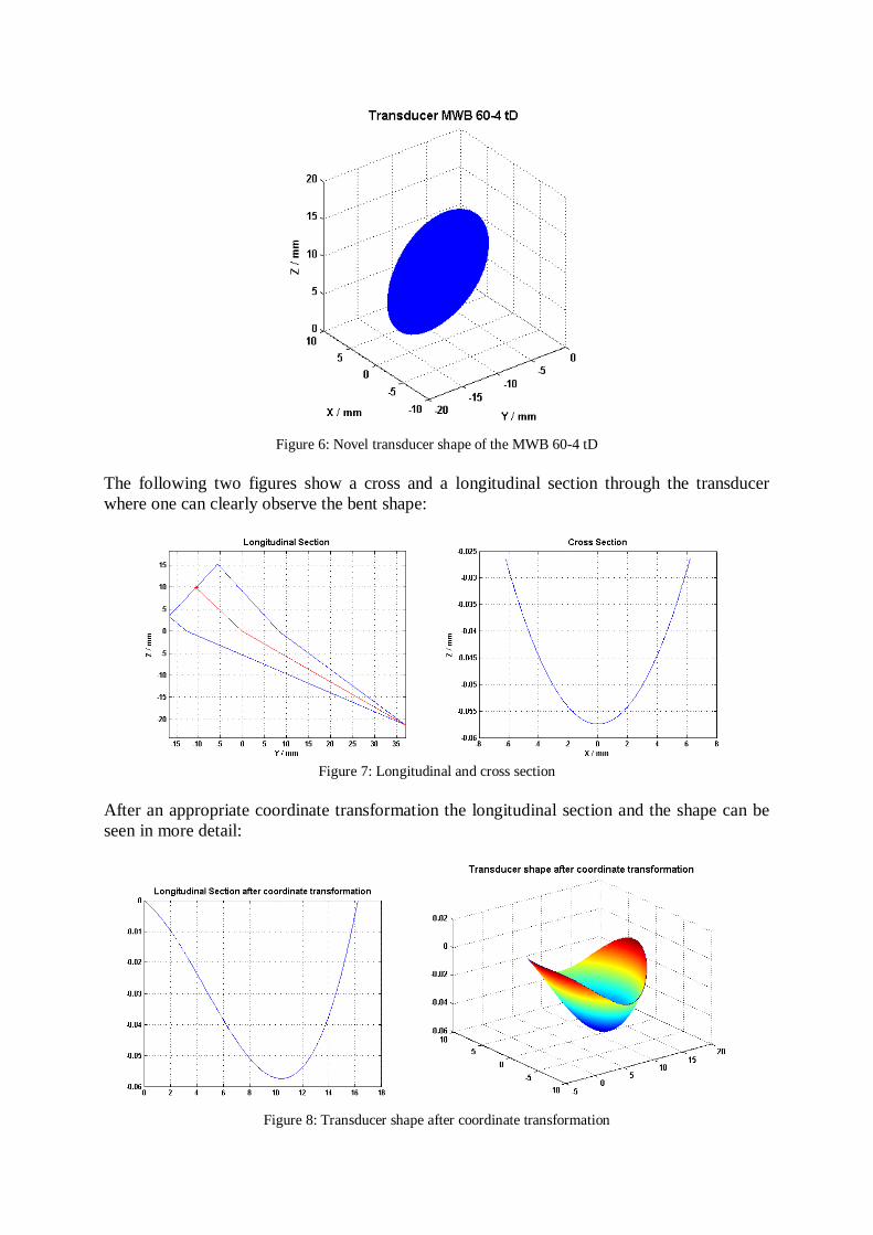
Figure 6: Novel transducer shape of the MWB 60-4 tD
The following two figures show a cross and a longitudinal section through the transducer where one can clearly observe the bent shape:
Figure 7: Longitudinal and cross section
After an appropriate coordinate transformation the longitudinal section and the shape can be seen in more detail:
Figure 8: Transducer shape after coordinate transformation
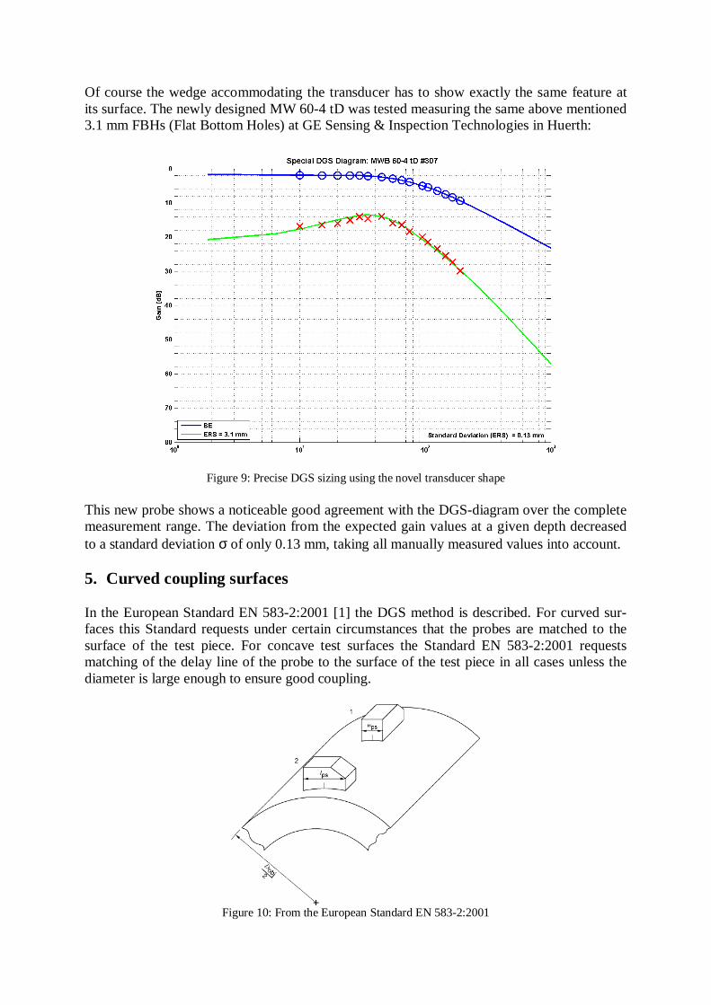
Of course the wedge accommodating the transducer has to show exactly the same feature at its surface. The newly designed MW 60-4 tD was tested measuring the same above mentioned 3.1 mm FBHs (Flat Bottom Holes) at GE Sensing & Inspection Technologies in Huerth:
Figure 9: Precise DGS sizing using the novel transducer shape This new probe shows a noticeable good agreement with the DGS-diagram over the complete measurement range. The deviation from the expected gain values at a given depth decreased to a standard deviation σ of only 0.13 mm, taking all manually measured values into account. 5. Curved coupling surfaces In the European Standard EN 583-2:2001 [1] the DGS method is described. For curved sur-faces this Standard requests under certain circumstances that the probes are matched to the surface of the test piece. For concave test surfaces the Standard EN 583-2:2001 requests matching of the delay line of the probe to the surface of the test piece in all cases unless the diameter is large enough to ensure good coupling.
Figure 10: From the European Standard EN 583-2:2001
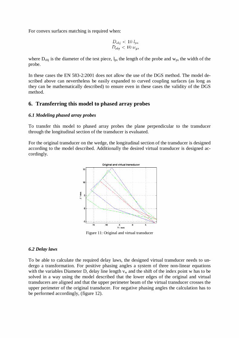
For convex surfaces matching is required when: where Dobj is the diameter of the test piece, lps the length of the probe and wps the width of the probe. In these cases the EN 583-2:2001 does not allow the use of the DGS method. The model de-scribed above can nevertheless be easily expanded to curved coupling surfaces (as long as they can be mathematically described) to ensure even in these cases the validity of the DGS method. 6. Transferring this model to phased array probes 6.1 Modeling phased array probes To transfer this model to phased array probes the plane perpendicular to the transducer through the longitudinal section of the transducer is evaluated. For the original transducer on the wedge, the longitudinal section of the transducer is designed according to the model described. Additionally the desired virtual transducer is designed ac-cordingly.
Figure 11: Original and virtual transducer
6.2 Delay laws To be able to calculate the required delay laws, the designed virtual transducer needs to un-dergo a transformation. For positive phasing angles a system of three non-linear equations with the variables Diameter D, delay line length vw and the shift of the index point w has to be solved in a way using the model described that the lower edges of the original and virtual transducers are aligned and that the upper perimeter beam of the virtual transducer crosses the upper perimeter of the original transducer. For negative phasing angles the calculation has to be performed accordingly, (figure 12).
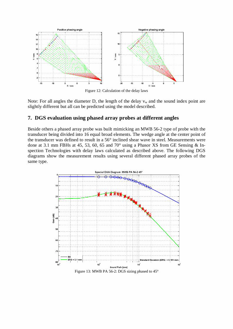
Figure 12: Calculation of the delay laws
Note: For all angles the diameter D, the length of the delay vw and the sound index point are slightly different but all can be predicted using the model described.
7. DGS evaluation using phased array probes at different angles Beside others a phased array probe was built mimicking an MWB 56-2 type of probe with the transducer being divided into 16 equal broad elements. The wedge angle at the center point of the transducer was defined to result in a 56° inclined shear wave in steel. Measurements were done at 3.1 mm FBHs at 45, 53, 60, 65 and 70° using a Phasor XS from GE Sensing & In-spection Technologies with delay laws calculated as described above. The following DGS diagrams show the measurement results using several different phased array probes of the same type.
Figure 13: MWB PA 56-2: DGS sizing phased to 45°
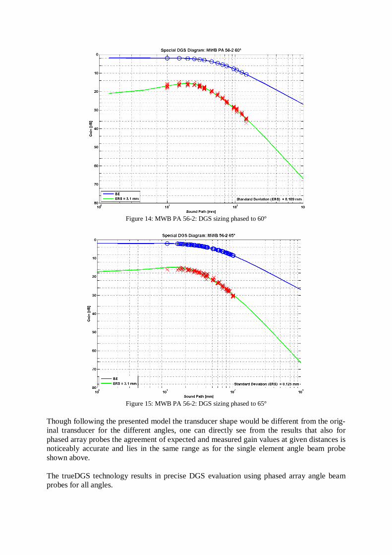
Figure 14: MWB PA 56-2: DGS sizing phased to 60°
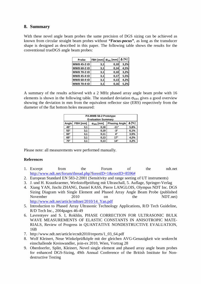
Figure 15: MWB PA 56-2: DGS sizing phased to 65°
Though following the presented model the transducer shape would be different from the orig-inal transducer for the different angles, one can directly see from the results that also for phased array probes the agreement of expected and measured gain values at given distances is noticeably accurate and lies in the same range as for the single element angle beam probe shown above. The trueDGS technology results in precise DGS evaluation using phased array angle beam probes for all angles.
8. Summary With these novel angle beam probes the same precision of DGS sizing can be achieved as known from circular straight beam probes without “Focus-pocus”, as long as the transducer shape is designed as described in this paper. The following table shows the results for the conventional trueDGS angle beam probes:
A summary of the results achieved with a 2 MHz phased array angle beam probe with 16 elements is shown in the following table. The standard deviation σERS gives a good overview showing the deviation in mm from the equivalent reflector size (ERS) respectively from the diameter of the flat bottom holes measured:
Please note: all measurements were performed manually. References 1. Excerpt from the Forum of the ndt.net
http://www.ndt.net/forum/thread.php?forenID=1&rootID=8596# 2. European Standard EN 583-2:2001 (Sensitivity and range seeting of UT instruments) 3. J. und H. Krautkraemer, Werkstoffprüfung mit Ultraschall, 5. Auflage, Springer-Verlag 4. Xiang YAN, Jinchi ZHANG, Daniel KASS, Pierre LANGLOIS, Olympus NDT Inc. DGS
Sizing Diagram with Single Element and Phased Array Angle Beam Probe (published November 2010 on the NDT.net) http://www.ndt.net/article/ndtnet/2010/14_Yan.pdf
5. Introduction to Phased Array Ultrasonic Technology Applications, R/D Tech Guideline, R/D Tech Inc., 2004pages 46-49
6. Lavrentyev and S. I, Rokhlin, PHASE CORRECTION FOR ULTRASONIC BULK WAVE MEASUREMENTS OF ELASTIC CONSTANTS IN ANISOTROPIC MATE-RIALS, Review of Progress in QUANTATIVE NONDESTRUCTIVE EVALUATION, 16B
7. http://www.ndt.net/article/ecndt2010/reports/1_03_64.pdf 8. Wolf Kleinert, Neue Winkelprüfköpfe mit der gleichen AVG-Genauigkeit wie senkrecht
einschallende Kreiswandler, join-ex 2010, Wien, Vortrag 28 9. Oberdoerfer, Splitt, Kleinert, Novel single element and phased array angle beam probes
for enhanced DGS-Sizing, 49th Annual Conference of the British Institute for Non-destructive Testing
Probe FBH [mm] σσσσERS [mm] ∆∆∆∆ [%]
MWB 45-2 tD 3,1 0,10 3,2%
MWB 60-2 tD 3,1 0,14 4,5%
MWB 70-2 tD 3,1 0,10 3,2%
MWB 45-4 tD 3,1 0,17 5,5%
MWB 60-4 tD 3,1 0,13 4,2%
MWB 70-4 tD 3,1 0,16 5,2%
Angle FBH [mm] σσσσERS [mm] Phasing Angle ∆∆∆∆ [%]
45° 3,1 0,18 -11° 5,8%53° 3,1 0,19 -3° 6,1%60° 3,1 0,11 4° 3,5%65° 3,1 0,13 17° 4,2%70° 3,1 0,13 14° 4,2%
PA-MWB 56-2 PrototypeEvaluation Summary


![Bibliography - tphys.physik.uni-tuebingen.de · [29] John C. Baez, Javier .P Muniain: Gauge Fields, Knots, and Gravity , World Scienti c, 1994 [30] Hagen Kleinert: Gauge Fields in](https://img.pdfslide.net/doc/110x75/5b8125b17f8b9a32738bab66/bibliography-tphys-29-john-c-baez-javier-p-muniain-gauge-fields-knots.jpg)


![Gauge Fields in Condensed Matter [H. Kleinert]](https://img.pdfslide.net/doc/110x75/55cf8fd9550346703ba086b4/gauge-fields-in-condensed-matter-h-kleinert.jpg)
