Embed Size (px)
Citation preview
2nd Generation Intel® Core™ Processor Family MobileThermal Design Guide for Embedded Applications
March 2013
Revision 003
Order Number: 325676

2nd Generation Intel® Core™ Processor Family MobileMarch 2013 TDGOrder Number: 325676 2
INFORMATION IN THIS DOCUMENT IS PROVIDED IN CONNECTION WITH INTEL PRODUCTS. NO LICENSE, EXPRESS OR IMPLIED, BY ESTOPPEL OR OTHERWISE, TO ANY INTELLECTUAL PROPERTY RIGHTS IS GRANTED BY THIS DOCUMENT. EXCEPT AS PROVIDED IN INTEL'S TERMS AND CONDITIONS OF SALE FOR SUCH PRODUCTS, INTEL ASSUMES NO LIABILITY WHATSOEVER AND INTEL DISCLAIMS ANY EXPRESS OR IMPLIED WARRANTY, RELATING TO SALE AND/OR USE OF INTEL PRODUCTS INCLUDING LIABILITY OR WARRANTIES RELATING TO FITNESS FOR A PARTICULAR PURPOSE, MERCHANTABILITY, OR INFRINGEMENT OF ANY PATENT, COPYRIGHT OR OTHER INTELLECTUAL PROPERTY RIGHT. A "Mission Critical Application" is any application in which failure of the Intel Product could result, directly or indirectly, in personal injury or death. SHOULD YOU PURCHASE OR USE INTEL'S PRODUCTS FOR ANY SUCH MISSION CRITICAL APPLICATION, YOU SHALL INDEMNIFY AND HOLD INTEL AND ITS SUBSIDIARIES, SUBCONTRACTORS AND AFFILIATES, AND THE DIRECTORS, OFFICERS, AND EMPLOYEES OF EACH, HARMLESS AGAINST ALL CLAIMS COSTS, DAMAGES, AND EXPENSES AND REASONABLE ATTORNEYS' FEES ARISING OUT OF, DIRECTLY OR INDIRECTLY, ANY CLAIM OF PRODUCT LIABILITY, PERSONAL INJURY, OR DEATH ARISING IN ANY WAY OUT OF SUCH MISSION CRITICAL APPLICATION, WHETHER OR NOT INTEL OR ITS SUBCONTRACTOR WAS NEGLIGENT IN THE DESIGN, MANUFACTURE, OR WARNING OF THE INTEL PRODUCT OR ANY OF ITS PARTS. Intel may make changes to specifications and product descriptions at any time, without notice. Designers must not rely on the absence or characteristics of any features or instructions marked "reserved" or "undefined". Intel reserves these for future definition and shall have no responsibility whatsoever for conflicts or incompatibilities arising from future changes to them. The information here is subject to change without notice. Do not finalize a design with this information. The products described in this document may contain design defects or errors known as errata which may cause the product to deviate from published specifications. Current characterized errata are available on request. Contact your local Intel sales office or your distributor to obtain the latest specifications and before placing your product order. Copies of documents which have an order number and are referenced in this document, or other Intel literature, may be obtained by calling 1-800-548-4725, or go to: http://www.intel.com/design/literature.htmDesigners must not rely on the absence or characteristics of any features or instructions marked “reserved” or “undefined.” Intel reserves these for future definition and shall have no responsibility whatsoever for conflicts or incompatibilities arising from future changes to them.The 2nd Generation Intel® Core™ Processor Family Mobile may contain design defects or errors known as errata which may cause the product to deviate from published specifications. Current characterized errata are available on request.AnyPoint, AppChoice, BoardWatch, BunnyPeople, CablePort, Celeron, Chips, CT Media, Dialogic, DM3, EtherExpress, ETOX, FlashFile, i386, i486, i960, iCOMP, InstantIP, Intel, Intel Centrino, Intel logo, Intel386, Intel486, Intel740, IntelDX2, IntelDX4, IntelSX2, Intel Create & Share, Intel GigaBlade, Intel InBusiness, Intel Inside, Intel Inside logo, Intel NetBurst, Intel NetMerge, Intel NetStructure, Intel Play, Intel Play logo, Intel SingleDriver, Intel SpeedStep, Intel StrataFlash, Intel TeamStation, Intel Xeon, Intel XScale, IPLink, Itanium, MCS, MMX, MMX logo, Optimizer logo, OverDrive, Paragon, PC Dads, PC Parents, PDCharm, Pentium, Pentium II Xeon, Pentium III Xeon, Performance at Your Command, RemoteExpress, SmartDie, Solutions960, Sound Mark, StorageExpress, The Computer Inside., The Journey Inside, TokenExpress, VoiceBrick, VTune, and Xircom are trademarks or registered trademarks of Intel Corporation or its subsidiaries in the United States and other countries.*Other names and brands may be claimed as the property of others.Copyright © 2013, Intel Corporation. All Rights Reserved.

2nd Generation Intel® Core™ Processor Family Mobile TDG—Contents
Contents
1.0 Introduction ............................................................................................................. 61.1 Design Flow ....................................................................................................... 61.2 Definition of Terms ............................................................................................. 71.3 Referenced Documents........................................................................................ 81.4 Thermal Design Tool Availability ........................................................................... 8
2.0 Package Information................................................................................................. 92.1 Sacrificial Corner Balls ....................................................................................... 192.2 Land Side Capacitors (LSC) ................................................................................ 192.3 Die Side Capacitors (DSC).................................................................................. 20
3.0 Thermal Management ............................................................................................. 223.1 Thermal Design Power and Junction Temperatures ................................................ 22
3.1.1 Turbo Considerations.............................................................................. 233.1.2 Platform Environment Control Interface (PECI) .......................................... 23
3.1.2.1 Fan Speed Control with Digital Thermal Sensor............................. 24
4.0 Mechanical Specifications ....................................................................................... 254.1 Package Mechanical Requirements ...................................................................... 25
4.1.1 Die Pressure (Load Upper/Lower Limit) ..................................................... 254.2 Package Keep-Out Zones Requirements ............................................................... 254.3 Board Level Keep-Out Zone Requirements............................................................ 25
5.0 Thermal Solution Requirements .............................................................................. 285.1 Thermal Solution Characterization....................................................................... 28
5.1.1 Calculating the Required Thermal Performance for the 2nd Generation Intel® Core™ Processor Family Mobile................................................................ 29
6.0 Reference Thermal Solutions .................................................................................. 316.1 Performance Targets ......................................................................................... 316.2 Mini-ITX* Reference Heatsink............................................................................. 31
6.2.1 Mechanical Design ................................................................................. 326.2.2 Keep-Out Zone Requirements.................................................................. 326.2.3 Thermal Performance ............................................................................. 32
6.3 CompactPCI* Reference Thermal Solutions........................................................... 336.4 Keep-Out Zone Requirements............................................................................. 336.5 Heatsink Fastener Assembly............................................................................... 336.6 Thermal Interface Material (TIM) ........................................................................ 346.7 Heatsink Orientation ......................................................................................... 35
7.0 Thermal Metrology .................................................................................................. 367.1 Die Temperature Measurements ......................................................................... 367.2 Power Simulation Software................................................................................. 367.3 Additional Thermal Features ............................................................................... 367.4 Local Ambient Temperature Measurement Guidelines............................................. 36
7.4.1 Active Heatsink Measurements ................................................................ 377.4.2 Passive Heatsink Measurements............................................................... 37
A Thermal Solution Component Suppliers................................................................... 40
B Mechanical Drawings .............................................................................................. 41
2nd Generation Intel® Core™ Processor Family MobileTDG March 20133 Order Number: 325676
Figures—2nd Generation Intel® Core™ Processor Family Mobile TDG
Figures1 Thermal Design Process ..............................................................................................72 3-D View of Top/ Bottom of BGA1023 2C Package for the 2nd Generation Intel® Core™
Processor Family Mobile ............................................................................................103 3-D View of Top/ Bottom of BGA1023 4C/2CF Package for the 2nd Generation Intel®
Core™ Processor Family Mobile ..................................................................................104 3-D View of Top/ Bottom of rPGA988 2C Package for the 2nd Generation Intel® Core™
Processor Family Mobile ............................................................................................105 3-D View of Top/ Bottom of rPGA988 4C/2CF Package for the 2nd Generation Intel®
Core™ Processor Family Mobile ..................................................................................106 2nd Generation Intel® Core™ Processor Family Mobile BGA1023 2C Package...................117 2nd Generation Intel® Core™ Processor Family Mobile BGA1023 2C Package Keep-Out
Zones..................................................................................................................... 128 2nd Generation Intel® Core™ Processor Family Mobile BGA1023 4C/2CF Package ............139 2nd Generation Intel® Core™ Processor Family Mobile BGA1023 4C/2CF Package
Keep-Out Zones.......................................................................................................1410 2nd Generation Intel® Core™ Processor Family Mobile rPGA988 2C Package....................1511 2nd Generation Intel® Core™ Processor Family Mobile rPGA988 2C Package Keep-Out
Zones..................................................................................................................... 1612 2nd Generation Intel® Core™ Processor Family Mobile rPGA988 4C/2CF Package .............1713 2nd Generation Intel® Core™ Processor Family Mobile rPGA988 4C/2CF Package
Keep-Out Zones.......................................................................................................1814 Example of Sacrificial Corner Balls ..............................................................................1915 Example of Land Side Capacitors Located on the Bottom of a PGA Package ......................2016 Example of Die Side Capacitors Located on the Die Side of a Package .............................2117 2nd Generation Intel® Core™ Processor Family Mobile BGA Board Keep-Out Zones ..........2618 2nd Generation Intel® Core™ Processor Family Mobile rPGA Board Keep-Out Zones .........2719 Processor Thermal Characterization Parameter Relationships .........................................2920 Mini-ITX Reference Heatsink......................................................................................3221 CompactPCI* Reference Heatsink Thermal Performance vs. Approach Velocity .................3322 CompactPCI* Reference Heatsink Assembly.................................................................3423 Heatsink Orientation Relative to Airflow Direction .........................................................3524 Measuring TLA with an Active Heatsink .......................................................................3825 Measuring TLA with a Passive Heatsink .......................................................................3926 Mini-ITX* Reference Heatsink PCB Keep Out Zone Requirements ....................................4227 Mini-ITX* Reference Heatsink Assembly (Sheet 1 of 2)..................................................4328 Mini-ITX* Reference Heatsink Assembly (Sheet 2 of 2)..................................................4429 cPCI* Reference Heatsink PCB Keep Out Zone Requirements .........................................4530 cPCI* Reference Heatsink Assembly (Sheet 1 of 2) .......................................................4631 cPCI* Reference Heatsink Assembly (Sheet 2 of 2) .......................................................4732 cPCI* Reference Heatsink .........................................................................................48
Tables1 Definition of Terms.....................................................................................................72 Thermal Specifications for 2nd Generation Intel® Core™ Processor Family Mobile.............233 Boundary Conditions and Performance Targets for 2nd Generation Intel® Core™ Processor
Family Mobile ..........................................................................................................314 Suppliers ................................................................................................................405 Mechanical Drawings ................................................................................................41
2nd Generation Intel® Core™ Processor Family Mobile March 2013 TDGOrder Number: 325676 4

2nd Generation Intel® Core™ Processor Family Mobile TDG—Tables
Revision History
Date Revision Description
June 2010 001 Initial release of this document
May 2012 002 Updated to include 2CF package designs
March 2013 003 Fixed typo in Equation 4
2nd Generation Intel® Core™ Processor Family MobileTDG March 20135 Order Number: 325676

Introduction—2nd Generation Intel® Core™ Processor Family Mobile TDG
1.0 Introduction
The power needs of electronic components has risen along with the increase in complexity of computer systems. To ensure quality, reliability, and performance goals are met over the product’s life cycle, the heat generated by the device must be properly dissipated. Typical methods to improve heat dissipation include selective use of airflow ducting, and/or the use of heatsinks.
The goals of this document are to:• Specify the thermal and mechanical specification for the device.• Describe a reference thermal solution that meets the specifications.
A properly designed thermal solution will adequately cool the device at or below the thermal specification. This is accomplished by providing a suitable local-ambient temperature, ensuring adequate local airflow, and minimizing the die to local-ambient thermal resistance. Operation outside the functional limits can degrade system performance and may cause permanent changes in the operating characteristics of the component.
This document describes thermal design guidelines for the 2nd Generation Intel® Core™ Processor Family Mobile in the micro-Flip Chip Pin Grid Array (micro-FCPGA988) package and the micro-Flip Chip Ball Grid Array (micro-FCBGA1023) package. The information provided in this document is for reference only, and additional validation must be performed prior to implementing the designs into final production. The intent of this document is to assist each original equipment manufacturer (OEM) with the development of thermal solutions for their individual designs. The final heatsink solution, including the heatsink, attachment method, and thermal interface material (TIM) must comply with the mechanical design, environmental, and reliability requirements delineated in the processor datasheet. It is the responsibility of each OEM to validate the thermal solution design with their specific applications.
This document addresses thermal and mechanical design specifications for the 2nd Generation Intel® Core™ Processor Family Mobile only. For thermal design information on other Intel components, refer to their respective thermal mechanical design guidelines.
1.1 Design FlowIntel provides several tools to assist in the development of a reliable, cost-effective thermal solution. Figure 1 illustrates a typical thermal solution design process with available tools noted. The tools are available through your local Intel field sales representative.
2nd Generation Intel® Core™ Processor Family MobileMarch 2013 TDGOrder Number: 325676 6

2nd Generation Intel® Core™ Processor Family Mobile TDG-Introduction
1.2 Definition of Terms
Figure 1. Thermal Design Process
Table 1. Definition of Terms (Sheet 1 of 2)
Term Definition
FCPGA Flip Chip Pin Grid Array. A pin grid array packaging technology where the die is exposed on the package substrate.
FCBGA Flip Chip Ball Grid Array. A ball grid array packaging technology where the die is exposed on the package substrate.
TJUNCTION-MAX Maximum allowed component (junction) temperature. Also referred to as TJ-MAX
TDP Thermal Design Power. Thermal solutions should be designed to dissipate this target power level.
TLALocal ambient temperature. This is the temperature measured inside the chassis, approximately 1 inch upstream of a component heatsink. Also referred to as TA.
JA
Junction-to-ambient thermal characterization parameter. A measure of heatsink thermal performance using the total package power. Defined as (T JUNCTION – TLA) / Total Package Power
TIM
Thermal interface material thermal characterization parameter. A measure of thermal interface material performance using total package power. Defined as (T CASE – T JUNCTION)/ Total Package Power. Also referred to as JS.
SA
Sink-to-ambient thermal characterization parameter. A measure of heatsink thermal performance using total package power. Defined as (T SINK – T JUNCTION)/ Total Package Power.
C Degrees in Celsius
CFM Volumetric airflow rate in cubic feet per minute
in. Inches
LFM Airflow velocity in linear feet per minute
PCB Printed circuit board
TSINK Heatsink temperature measured on the underside of the heatsink base.
TIMThermal Interface Material – the thermally conductive compound between the heatsink and die. This material fills air gaps and voids, and enhances spreading of the heat from the die to the heatsink.
2nd Generation Intel® Core™ Processor Family MobileTDG March 20137 Order Number: 325676

Introduction—2nd Generation Intel® Core™ Processor Family Mobile TDG
1.3 Referenced DocumentsReaders should also be familiar with material and concepts presented in the following documents:
• 2nd Generation Intel® Core™ Processor Family Mobile Datasheet- Volume One Doc#324692-001
• 2nd Generation Intel® Core™ Processor Family Mobile Datasheet- Volume Two Doc#324803-001
• Huron River Thermal Mechanical Design Guide - Doc#445771• rPGA988/989 Socket Application Guide - Doc#419940• Huron River Thermal Models (FloTHERM*/Icepak*)- Doc# 439914
1.4 Thermal Design Tool AvailabilityIntel provides thermal simulation models of the device and a thermal model user’s guide to aid system designers in simulating, analyzing, and optimizing thermal solutions in an integrated, system-level environment. The models are for use with commercially available Computational Fluid Dynamics (CFD)-based thermal analysis tools including FloTHERM* (version 8.1 or higher) by Mentor Graphics or Icepak* by ANSYS.
U A unit of measure used to define server rack spacing height. 1U is equal to 1.75 inches, 2U equals 3.50 inches, etc.
W Watt
TFAN Represents the temperature at which fans must be at full speed
Table 1. Definition of Terms (Sheet 2 of 2)
Term Definition
2nd Generation Intel® Core™ Processor Family MobileMarch 2013 TDGOrder Number: 325676 8

2nd Generation Intel® Core™ Processor Family Mobile TDG-Package Information
2.0 Package Information
The 2nd Generation Intel® Core™ Processor Family Mobile utilizes a 31X24 mm, 1023-ball micro-FCBGA (BGA1023) package and 37.5 x 37.5 mm, 988-pin micro-FCPGA (rPGA988) package. For both micro-FCPGA and micro-FCBGA processors, there will be two different package designs that either have a 2C (2-Core) or a 4C (4-Core) die with the only difference being the die size. Also included in the package designs are 2CF (2-Core Fused) die, meaning a 2C fused from a 4C die. A 2CF die is the same size as a 4C die therefore, it is important to discern between 2C and 2CF before integrating the processor into a system design. Refer to Table 2 for core count vs. active core list. Refer to the device’s most recent datasheet for up-to-date information. In the event of conflict, the device’s datasheet supersedes data presented in this document.
The processors in the micro-FCPGA package connect to the motherboard through a 988-pin surface mount, Zero Insertion Force (ZIF) socket. A description of the socket can be found in the rPGA988/989 Socket Application Guide.
The land-side capacitors are electrically conductive, so avoid contacting the capacitors with any other electrically conductive materials. Doing so may short the capacitors and possibly damage the device or render it inactive.
The processor package has mechanical load limits that are specified in the processor datasheet. These load limits should not be exceeded during heatsink installation, removal, mechanical stress testing, or standard shipping conditions. The heatsink mass can also add additional dynamic compressive load to the package during a mechanical shock event. Amplification factors due to the impact force during shock must be taken into account in dynamic load calculations. The total combination of dynamic and static compressive load should not then exceed the processor datasheet compressive dynamic load specification during a vertical shock. It is not recommended to use any portion of the processor substrate as a mechanical reference or load bearing surface in either static or dynamic compressive load conditions.
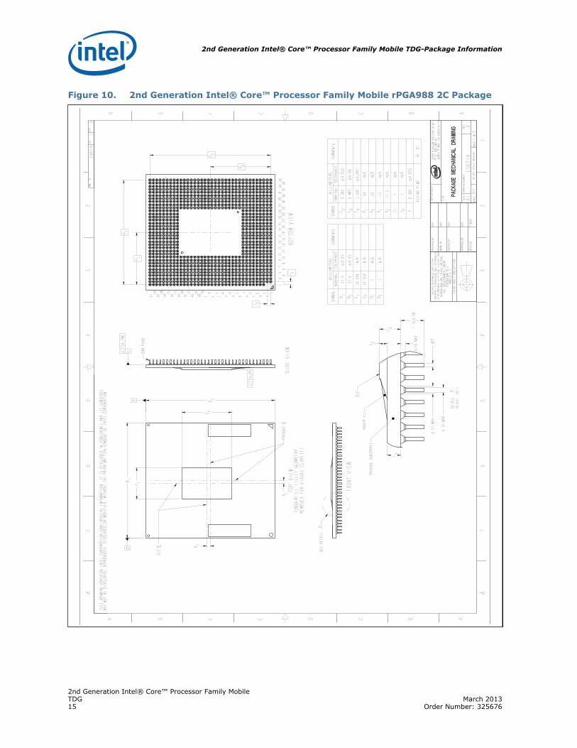
Figure 2 through Figure 5 show 3-dimensional, top and bottom views of the 2nd Generation Intel® Core™ Processor Family Mobile rPGA988 and BGA1023 packages in 2C and 4C/2CF designs. Figure 6 through Figure 13 contain:
• Detailed mechanical dimensions for all packages• Keep-out zones for thermal attach hardware corresponding to each of the packages
outline.
2nd Generation Intel® Core™ Processor Family MobileTDG March 20139 Order Number: 325676

Package Information—2nd Generation Intel® Core™ Processor Family Mobile TDG
Figure 2. 3-D View of Top/ Bottom of BGA1023 2C Package for the 2nd Generation Intel® Core™ Processor Family Mobile
Figure 3. 3-D View of Top/ Bottom of BGA1023 4C/2CF Package for the 2nd Generation Intel® Core™ Processor Family Mobile
Figure 4. 3-D View of Top/ Bottom of rPGA988 2C Package for the 2nd Generation Intel® Core™ Processor Family Mobile
Figure 5. 3-D View of Top/ Bottom of rPGA988 4C/2CF Package for the 2nd Generation Intel® Core™ Processor Family Mobile
2nd Generation Intel® Core™ Processor Family MobileMarch 2013 TDGOrder Number: 325676 10

2nd Generation Intel® Core™ Processor Family Mobile TDG-Package Information
Figure 6. 2nd Generation Intel® Core™ Processor Family Mobile BGA1023 2C Package
2nd Generation Intel® Core™ Processor Family MobileTDG March 201311 Order Number: 325676

Package Information—2nd Generation Intel® Core™ Processor Family Mobile TDG
Figure 7. 2nd Generation Intel® Core™ Processor Family Mobile BGA1023 2C Package Keep-Out Zones
2nd Generation Intel® Core™ Processor Family MobileMarch 2013 TDGOrder Number: 325676 12

2nd Generation Intel® Core™ Processor Family Mobile TDG-Package Information
Figure 8. 2nd Generation Intel® Core™ Processor Family Mobile BGA1023 4C/2CF Package
2nd Generation Intel® Core™ Processor Family MobileTDG March 201313 Order Number: 325676
Package Information—2nd Generation Intel® Core™ Processor Family Mobile TDG
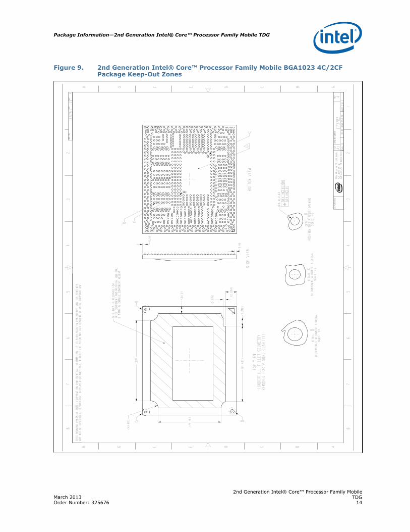
Figure 9. 2nd Generation Intel® Core™ Processor Family Mobile BGA1023 4C/2CF Package Keep-Out Zones
2nd Generation Intel® Core™ Processor Family MobileMarch 2013 TDGOrder Number: 325676 14
2nd Generation Intel® Core™ Processor Family Mobile TDG-Package Information
Figure 10. 2nd Generation Intel® Core™ Processor Family Mobile rPGA988 2C Package
2nd Generation Intel® Core™ Processor Family MobileTDG March 201315 Order Number: 325676

Package Information—2nd Generation Intel® Core™ Processor Family Mobile TDG
Figure 11. 2nd Generation Intel® Core™ Processor Family Mobile rPGA988 2C Package Keep-Out Zones
2nd Generation Intel® Core™ Processor Family MobileMarch 2013 TDGOrder Number: 325676 16

2nd Generation Intel® Core™ Processor Family Mobile TDG-Package Information
Figure 12. 2nd Generation Intel® Core™ Processor Family Mobile rPGA988 4C/2CF Package
2nd Generation Intel® Core™ Processor Family MobileTDG March 201317 Order Number: 325676

Package Information—2nd Generation Intel® Core™ Processor Family Mobile TDG
Figure 13. 2nd Generation Intel® Core™ Processor Family Mobile rPGA988 4C/2CF Package Keep-Out Zones
2nd Generation Intel® Core™ Processor Family MobileMarch 2013 TDGOrder Number: 325676 18

2nd Generation Intel® Core™ Processor Family Mobile TDG-Package Information
2.1 Sacrificial Corner BallsWith the shift to lead-free solder, the higher reflow temperature (typically required by lead-free surface mount packages) and the increase in moisture content are both inherent in lead-free designs. These factors are expected to cause a decrease in the shock or vibration performance of Intel packages. Intel is using the concept of “sacrificial corner balls” (also referred to as non-critical to function, nCTF) to improve the solder joint reliability performance in shock and vibration where board bending occurs. Sacrificial corner balls are the corner-most lead-free solder balls included in Intel’s BGA packages that are not used for any critical to function (CTF) signal routing. Corner solder balls are most susceptive to stress concentrations because of printed circuit board (PCB) layout shock, vibration, and bending. The concept of using sacrificial corner balls replaces “active” solder balls with mechanical solder balls which absorb maximum flexure stresses without negatively impacting electrical performance. Although using sacrificial corner balls provide about a 30 percent incremental shock margin, they are not a comprehensive platform solution; board flexure minimization techniques must still be considered. The corner-most solder balls provide a mechanical buffer to the CTF solder balls. Figure 14 shows an example of corner-most sacrificial solder balls on a BGA package.
2.2 Land Side Capacitors (LSC)A land side capacitor (LSC) is a device mounted on the back of a package. Refer to Figure 15 for an example of land side capacitors mounted on the back and at center of the pin side of a rPGA Package. Both rPGA988 and BGA1023 packages have LSC present. For the rPGA988 package, the maximum LSC height specification is 1.06mm.and side capacitors are only on the 2nd Generation Intel® Core™ Processor Family Mobile rPGA988 processor.
Figure 14. Example of Sacrificial Corner Balls
2nd Generation Intel® Core™ Processor Family MobileTDG March 201319 Order Number: 325676

Package Information—2nd Generation Intel® Core™ Processor Family Mobile TDG
Note: For enabled loading of the BGA1023 package, there can be contact between the LSC and board. Board designs will need to keep this into consideration to prevent LSC shorting.
2.3 Die Side Capacitors (DSC)A die side capacitor (DSC) is a device mounted on the top side of a package. Both rPGA988 and BGA1023 2nd Generation Intel® Core™ Processor Family Mobile have Die Side Capacitors. These capacitors have a maximum height specification of 0.40 mm for all of the packages from the top of the substrate of the package. See Figure 16 for an example of a capacitor mounted on the die side of a package.
Figure 15. Example of Land Side Capacitors Located on the Bottom of a PGA Package
2nd Generation Intel® Core™ Processor Family MobileMarch 2013 TDGOrder Number: 325676 20

2nd Generation Intel® Core™ Processor Family Mobile TDG-Package Information
Figure 16. Example of Die Side Capacitors Located on the Die Side of a Package
2nd Generation Intel® Core™ Processor Family MobileTDG March 201321 Order Number: 325676

Thermal Management—2nd Generation Intel® Core™ Processor Family Mobile TDG
3.0 Thermal Management
The thermal solution provides both the component-level and the system-level thermal management. To allow for the optimal operation and long-term reliability of Intel processor-based systems, the system/processor thermal solution should be designed so that the processor:
• Remains below the maximum junction temperature (TJ-Max) specification at the maximum thermal design power (TDP).
• Conforms to system constraints, such as system acoustics, system skin-temperatures, and exhaust-temperature requirements.
Caution: Thermal specifications in this chapter are on the component and package level and apply specifically to the Sandy Bridge processor. Operating the processor outside the specified limits may result in permanent damage to the processor and potentially other components in the system.
3.1 Thermal Design Power and Junction TemperaturesThe processor Thermal Design Power (TDP) is the maximum sustained power that should be used for design of the processor thermal solution. TDP represents an expected maximum sustained power from realistic applications. TDP may be exceeded for short periods of time or if running a “power virus” workload. Due to Intel® Turbo Boost Technology, applications are expected to run closer to TDP more often as the processor attempts to take advantage of available headroom in the platform to maximize performance.
The processor may also exceed the TDP for short durations after a period of lower power operation due to its turbo feature. This feature is intended to take advantage of available thermal capacity in the thermal solution for momentary high power operation. The duration and time of such operation can be controlled to match the thermal response of the system by platform runtime configurable registers within the processor. Please see the Sandy Bridge Turbo Implementation Guide and Sandy Bridge BIOS Writers Guide for details.
The processor integrates multiple CPU and graphics cores on a single die. This may result in differences in the power distribution across the die and must be considered when designing the thermal solution. The thermal solution, at a minimum, needs to ensure that the junction temperatures of both CPU and graphics cores do not exceed the maximum junction temperature (TJ-Max) limit while running TDP applications. Thermal management considerations can be found in the processor datasheet.
The TJ-Max and Thermal Design Power (TDP) specifications are listed in Table 2. The cooling capacity without a thermal solution is also minimal, so Intel requires the use of a heatsink for all usage conditions.
2nd Generation Intel® Core™ Processor Family MobileMarch 2013 TDGOrder Number: 325676 22

2nd Generation Intel® Core™ Processor Family Mobile TDG-Thermal Management
Table 2. Thermal Specifications for 2nd Generation Intel® Core™ Processor Family Mobile
Notes:1. The component TDPs given are not the maximum power the components can generate. Analysis
indicates that real applications are unlikely to cause the processor to consume the theoretical maximum power dissipation for sustained periods of time.
2. TDP workload may consist of a combination of a CPU-core intensive and a graphics-core intensive applications.
3. The thermal solution needs to ensure that the processor temperature does not exceed the maximum junction temperature (TJ-Max) limit, as measured by the DTS and the critical temperature bit.
4. The processor junction temperature is monitored by Digital Temperature Sensors (DTS). For DTS accuracy please refer to the 2nd Generation Intel® Core™ Processor Family Mobile Datasheet.
5. Digital Thermal Sensor (DTS) based fan speed control is required to achieve optimal thermal performance. Intel recommends full cooling capability well before the DTS reading reaches TJ-Max. An example of this would be Tj,Max - 10ºC.
6. At Tj of TJ-Max
3.1.1 Turbo Considerations
Intel® Turbo Boost Technology allows processor cores and integrated graphics cores to run faster than the baseline frequency. During a turbo event the processor can consume close to its maximum thermal power limit for sustained period. More importantly, processor thermal power can also briefly exceed its TDP power level. Turbo is invoked opportunistically and automatically as long as the processor is conforming to its temperature, power delivery, and current specification limits. Thus, thermal solutions and platform cooling that are designed to less than thermal design guidance might experience thermal and performance issues since more applications will tend to run at or near the maximum power limit for significant periods of time. Please see the Sandy Bridge Turbo Implementation Guide and Sandy Bridge BIOS Writers’ Guide.
3.1.2 Platform Environment Control Interface (PECI)
The Platform Environment Control Interface (PECI) is a one-wire interface that provides a communication channel between the Intel processor and chipset components to external monitoring devices. The processor uses a PECI interface for communication of processor thermal information to other devices on the platform. The processor provides a digital thermal sensor (DTS) for fan speed control. The DTS is calibrated at the factory to provide a digital representation of relative processor temperature. Averaged DTS values are read via the PECI interface.
The PECI physical layer is a self-clocked one-wire bus that begins each bit with a driven, rising edge from an idle level near zero volts. The duration of the signal driven high depends on whether the bit value is a Logic 0 or Logic 1. PECI also includes the variable data transfer rate established with every message. The single wire interface provides low board routing overhead for the multiple load connections in the congested
Segment # of on Die Cores
# of Functional
CoresTDP 1,2,6
(W)TJ-MAX 3,4,5
(C)TJ-MIN
3,4,5
(oC)
Standard Voltage 4 4 45 100 0
Standard Voltage 4 2 35 100 0
Standard Voltage 2 2 35 100 0
Low Voltage 4 2 25 100 0
Ultra Low Voltage 4 2 17 100 0
Ultra Low Voltage 2 2 17 100 0
Ultra Low Voltage 2 1 17 100 0
2nd Generation Intel® Core™ Processor Family MobileTDG March 201323 Order Number: 325676
Thermal Management—2nd Generation Intel® Core™ Processor Family Mobile TDG
routing area near the processor and chipset components. Bus speed, error checking, and low protocol overhead provides adequate link bandwidth and reliability to transfer critical device operating conditions and configuration information.
3.1.2.1 Fan Speed Control with Digital Thermal Sensor
Digital Thermal Sensor (DTS) based fan speed control is a recommended feature to achieve optimal thermal performance. As the temperature of the processor increases, a controller can read the DTS and then increase the speed of the thermal solution fan accordingly. The temperature at which the fan is programmed to run at maximum speed is called “TFAN”. Intel recommends reaching full fan speed well before the DTS reading reaches TJ-Max. An example of this would be TFAN = TJ-Max - 10ºC.
2nd Generation Intel® Core™ Processor Family MobileMarch 2013 TDGOrder Number: 325676 24

2nd Generation Intel® Core™ Processor Family Mobile TDG-Mechanical Specifications
4.0 Mechanical Specifications
This section includes specifications, package attributes, and mechanical drawings of the mobile 2nd Generation Intel® Core™ Processor Family Mobile. Also highlighted are key mechanical dimensions compatible with the reduced pitch pin grid array (rPGA989/988) socket to the corresponding family of CPU packages. These drawings can be used to determine printed circuit board (PCB) keep-out zones, the placement of discrete electronics and to gauge contact area and stack-up tolerances for thermal solution design.
4.1 Package Mechanical Requirements
4.1.1 Die Pressure (Load Upper/Lower Limit)From a die mechanical integrity standpoint, the maximum allowable normal die load is the lower of 15 lbs or 100 psi. For example, considering the 15 lbs load limit and the nominal die area of 1.45 cm2 (0.22 in2), this equates to a die pressure of 66.7 psi (below 100 psi specification). Considering the maximum pressure specification, the die load at this pressure would be 22.4 lbs, exceeding the 15 lbs. load limit. Thus, the heatsink clamping mechanism (spring loaded fasteners, spring clips, etc.) should not exceed 15 lbs specification.
From a Thermal Interface Material (TIM) performance standpoint, a minimum die pressure is required to ensure consistent and minimal TIM thermal resistance. This lower value is a function of the TIM used.
4.2 Package Keep-Out Zones RequirementsThe heatsink must not touch the package in the areas shown in Figure 7 and Figure 9. The heatsink should include a means to prevent the heatsink from forming an electrical short with the capacitors placed on the top side of the package. Reference thermal solutions could include machined z-stops into the base of the heatsink to prevent such an occurrence. The z-stops prevent the heatsink from inadvertently tilting when installed. Other methods are suitable including using electrically insulated gasket material at the base of the heatsink.
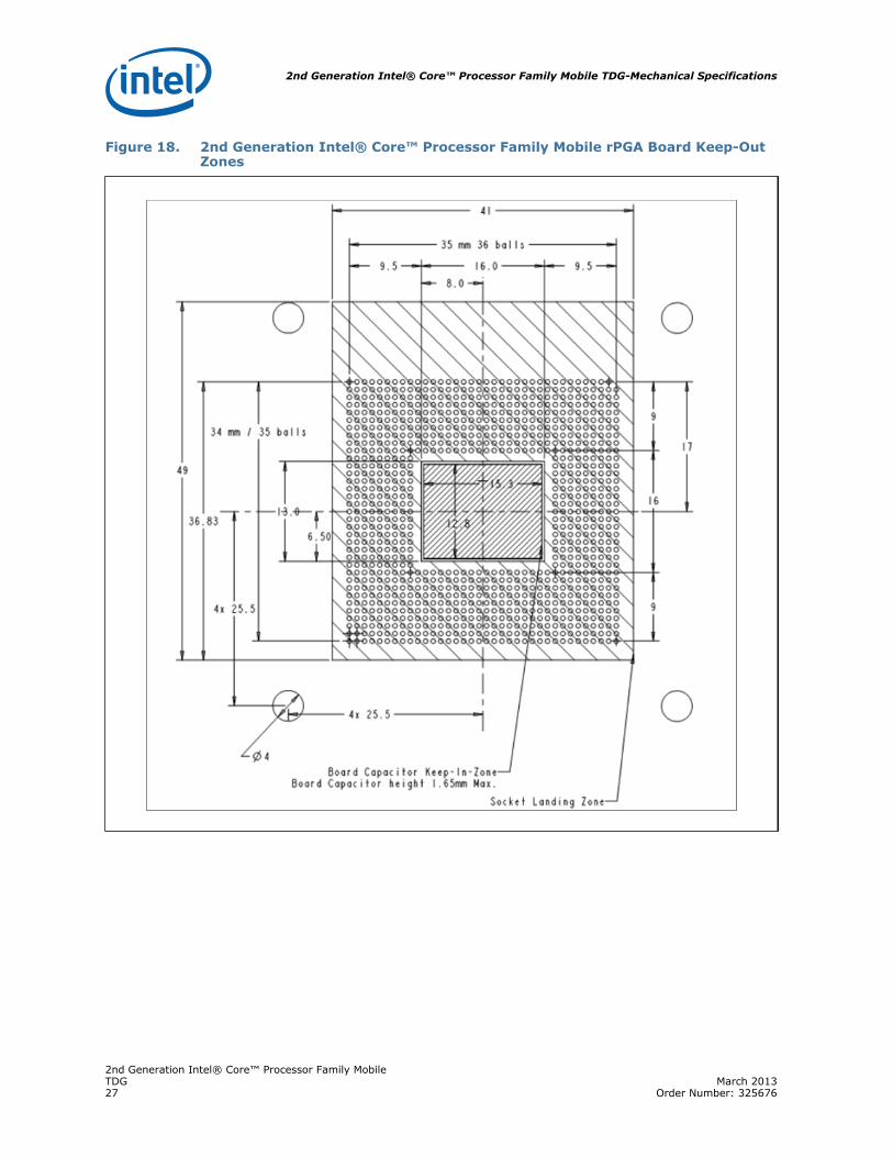
4.3 Board Level Keep-Out Zone RequirementsA general description of the keep-out zones and mounting hole pattern for the reference thermal solutions are shown in Figure 17 and Figure 18 for the rPGA988 and BGA1023 packages. Detailed drawings for the PCB keep out zones for Mini-ITX and CompactPCI* form factors are in Appendix B, “Mechanical Drawings”.
Components placed between the underside of the heatsink and motherboard cannot exceed 4.25 mm in height when using heatsinks that extend beyond the rPGA 988/989 socket envelope for the micro-FCPGA package.
2nd Generation Intel® Core™ Processor Family MobileTDG March 201325 Order Number: 325676

Mechanical Specifications—2nd Generation Intel® Core™ Processor Family Mobile TDG
Figure 17. 2nd Generation Intel® Core™ Processor Family Mobile BGA Board Keep-Out Zones
2nd Generation Intel® Core™ Processor Family MobileMarch 2013 TDGOrder Number: 325676 26
2nd Generation Intel® Core™ Processor Family Mobile TDG-Mechanical Specifications
Figure 18. 2nd Generation Intel® Core™ Processor Family Mobile rPGA Board Keep-Out Zones
2nd Generation Intel® Core™ Processor Family MobileTDG March 201327 Order Number: 325676

Thermal Solution Requirements—2nd Generation Intel® Core™ Processor Family Mobile TDG
5.0 Thermal Solution Requirements
5.1 Thermal Solution CharacterizationThe thermal characterization parameter, (“psi”), is used to characterize thermal solution performance, as well as compare thermal solutions in identical situations (i.e., heating source, local ambient conditions, etc.). It is defined by the following equation:
where,
JA = Junction-to-local ambient thermal characterization parameter (°C/W)
TJ-Max = Maximum allowed device temperature (°C)
TA = Local ambient temperature near the device (°C) (see Section 7.0 for measurement guidelines)
TDP = Thermal Design Power (W) at the socket level
The thermal characterization parameter assumes that all package power dissipation is through the thermal solution (heatsink), and is equal to TDP. A small percentage of the die power (< 5%) is dissipated through the package/socket/motherboard stack to the environment, and should not be considered as a means of thermal control.
The junction-to-local ambient thermal characterization parameter, JA, is comprised of JS, which includes the thermal interface material thermal characterization parameter, and of SA, the sink-to-local ambient thermal characterization parameter:
Where:
JS = Thermal characterization parameter from junction-to-sink, this also includes thermal resistance of the thermal interface material (TIM) (°C/W).
SA = Thermal characterization parameter from sink-to-local ambient (°C/W)
SA is a measure of the thermal characterization parameter from the bottom of the heatsink to the local ambient air. SA is dependent on the heatsink material, thermal conductivity, and geometry. It is also strongly dependent on the air velocity through
Equation 1. Junction-to-Local Ambient Thermal Characterization Parameter (JA)
Equation 2. Junction-to-Local Ambient Thermal Characterization Parameter
2nd Generation Intel® Core™ Processor Family MobileMarch 2013 TDGOrder Number: 325676 28

2nd Generation Intel® Core™ Processor Family Mobile TDG-Thermal Solution Requirements
the fins of the heatsink. Figure 19 illustrates the combination of the different thermal characterization parameters.
5.1.1 Calculating the Required Thermal Performance for the 2nd Generation Intel® Core™ Processor Family Mobile
Overall thermal performance, JA, is then defined using the thermal characterization parameter:
• Define a target component temperature TJUNCTION and corresponding TDP.• Define a target local ambient temperature, TA.
The following provides an illustration of how to determine the appropriate performance targets.
Assume:• TDP = 35W and TJUNCTION = 100° C• Local processor ambient temperature, TA = 55° C.
Using Equation 1, the maximum allowable resistance, junction-to-ambient, is calculated as:
To determine the required heatsink performance, a heatsink solution provider would need to determine JA performance for the selected TIM and mechanical load configuration. If the heatsink solution were designed to work with a TIM material performing at TIM 0.3°C/W, solving from Equation 2, the performance of the heatsink required is:
Figure 19. Processor Thermal Characterization Parameter Relationships
Equation 3. Maximum Allowable Resistance
2nd Generation Intel® Core™ Processor Family MobileTDG March 201329 Order Number: 325676

Thermal Solution Requirements—2nd Generation Intel® Core™ Processor Family Mobile TDG
It is evident from the above calculations that a reduction in the local ambient temperature can have a significant effect on the junction-to-ambient thermal resistance requirement. This effect can contribute to a more reasonable thermal solution including reduced cost, heatsink size, heatsink weight, or a lower system airflow rate.
Equation 4. Required Performance of the Heatsink
2nd Generation Intel® Core™ Processor Family MobileMarch 2013 TDGOrder Number: 325676 30
2nd Generation Intel® Core™ Processor Family Mobile TDG-Reference Thermal Solutions
6.0 Reference Thermal Solutions
Intel has developed reference thermal solutions designed to meet the cooling needs of embedded form factor applications. This chapter describes the overall requirements for the reference thermal solution including critical-to-function dimensions, operating environment, and verification criteria. This document details solutions that are compatible with Mini-ITX and CompactPCI* form factors.
The data in this section is based on test data of the reference thermal solutions. The mini-ITX* heatsink was tested as an assembly with a thermal test vehicle (TTV), thermal interface material, socket and test board. For the passive CompactPCI* thermal solution, test assemblies are placed in a rectangular duct connected to a wind tunnel with no upstream obstructions. Air flow is measured by means of a calibrated nozzle downstream of the unit under test. The thermal performance values shown in the charts to follow represent the mean resistance values plus the one-sided, 99% confidence interval.
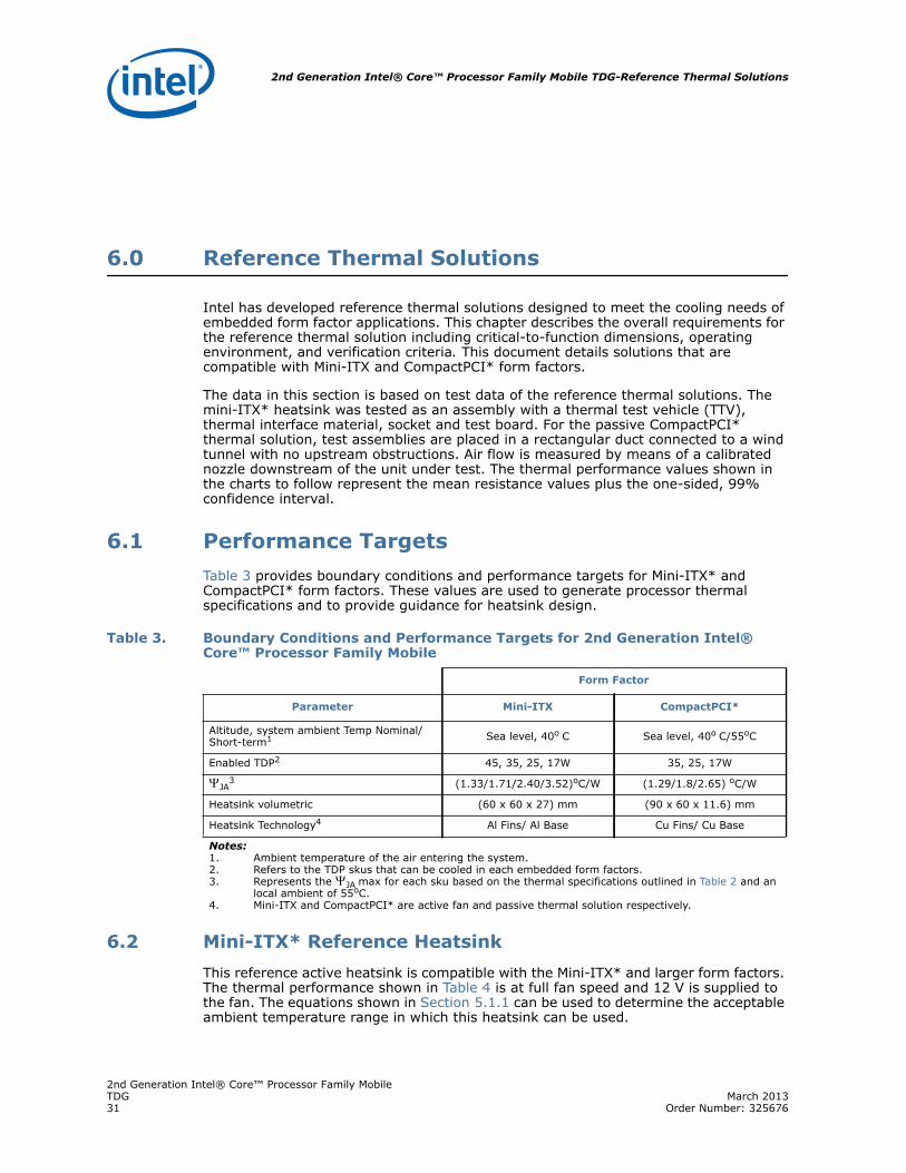
6.1 Performance TargetsTable 3 provides boundary conditions and performance targets for Mini-ITX* and CompactPCI* form factors. These values are used to generate processor thermal specifications and to provide guidance for heatsink design.
6.2 Mini-ITX* Reference HeatsinkThis reference active heatsink is compatible with the Mini-ITX* and larger form factors. The thermal performance shown in Table 4 is at full fan speed and 12 V is supplied to the fan. The equations shown in Section 5.1.1 can be used to determine the acceptable ambient temperature range in which this heatsink can be used.
Table 3. Boundary Conditions and Performance Targets for 2nd Generation Intel® Core™ Processor Family Mobile
Form Factor
Parameter Mini-ITX CompactPCI*
Altitude, system ambient Temp Nominal/Short-term1 Sea level, 40o C Sea level, 40o C/55oC
Enabled TDP2 45, 35, 25, 17W 35, 25, 17W
JA3 (1.33/1.71/2.40/3.52)oC/W (1.29/1.8/2.65) oC/W
Heatsink volumetric (60 x 60 x 27) mm (90 x 60 x 11.6) mm
Heatsink Technology4 Al Fins/ Al Base Cu Fins/ Cu Base
Notes:1. Ambient temperature of the air entering the system.2. Refers to the TDP skus that can be cooled in each embedded form factors.3. Represents the JA max for each sku based on the thermal specifications outlined in Table 2 and an
local ambient of 55oC. 4. Mini-ITX and CompactPCI* are active fan and passive thermal solution respectively.
2nd Generation Intel® Core™ Processor Family MobileTDG March 201331 Order Number: 325676

Reference Thermal Solutions—2nd Generation Intel® Core™ Processor Family Mobile TDG
6.2.1 Mechanical Design
The reference heatsink is shown in the figure below. The reference solution is an aluminum skived finned active fan solution with overall dimension of 60mm x 60mm x. The maximum heatsink height was constrained so that the total package height plus heatsink will not exceed maximum component height for the Mini-ITX* Form Factor. The heatsink uses spring fasteners and a backplate assembly (refer to Section 6.7) to mount to the PCB. Detailed drawings of this heatsink are provided in Appendix B.
6.2.2 Keep-Out Zone Requirements
The keep-out zone requirements on the PCB to use the enabled reference heatsinks are detailed in Appendix B, “Mechanical Drawings” for CompactPCI* because it extends beyond the footprint of the device, it is critical for the board designer to allocate space on the board for the heatsink foot print.
6.2.3 Thermal Performance
The performance of the heatsink is shown below. Based on the target boundary conditions, this heatsink can meet the thermal performance needed to cool the processor in the Mini-ITX form factor. However, it is up to the system designer to validate the entire thermal solution (heatsink, attach method, TIM) in its final intended system. The performance data is based on lab verification testing.
Figure 20. Mini-ITX Reference Heatsink
2nd Generation Intel® Core™ Processor Family MobileMarch 2013 TDGOrder Number: 325676 32

2nd Generation Intel® Core™ Processor Family Mobile TDG-Reference Thermal Solutions
6.3 CompactPCI* Reference Thermal SolutionsThis reference heatsink is compatible with CompactPCI* form factor and other small embedded blade form factor. Figure 21 outlines the heatsink thermal performance at various airflow rates. The equations shown in Section 5.1 can be used to determine the acceptable ambient temperature range at which this heatsink can be used based on available airflow.
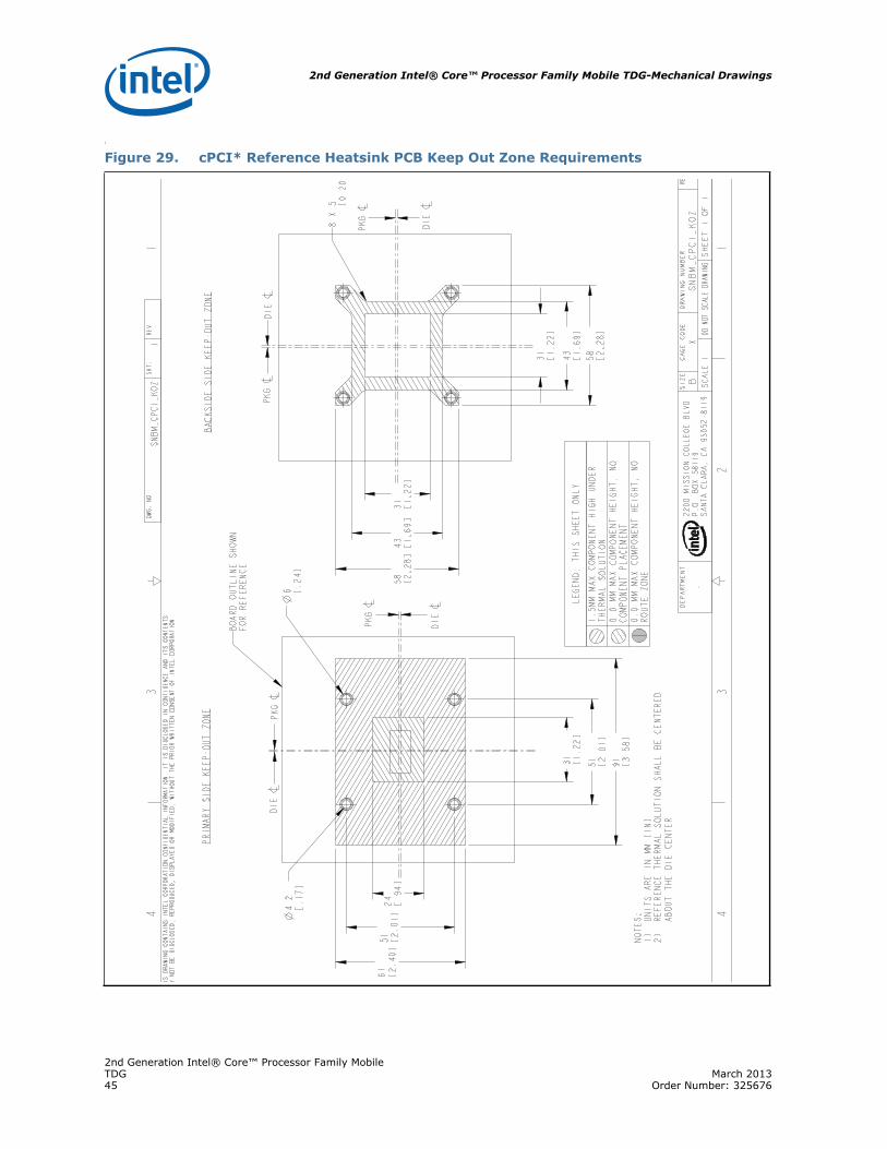
6.4 Keep-Out Zone RequirementsThe keep-out zone requirements on the PCB to use the enabled reference heatsinks are detailed in Appendix B, “Mechanical Drawings” for CompactPCI* because it extends beyond the footprint of the device, it is critical for the board designer to allocate space on the board for the heatsink foot print.
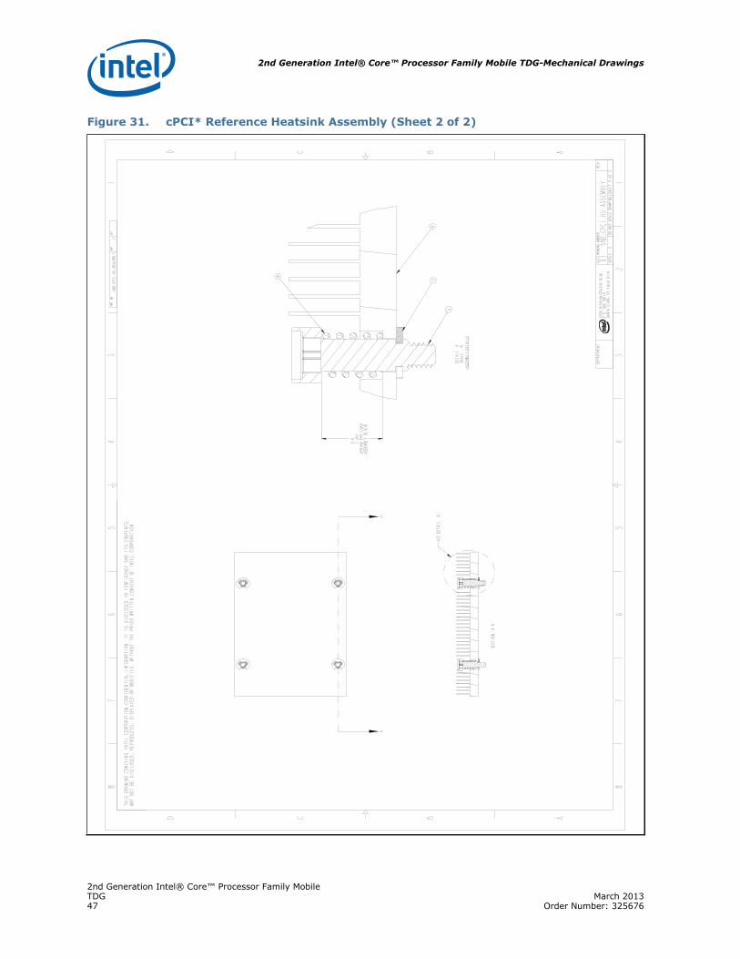
6.5 Heatsink Fastener AssemblyThe reference solutions use a screw, spring, and back plate assembly to attach the heatsink to the PCB as shown in Figure 22 for the CompactPCI* reference heat sink. The fastener assembly used on the reference heatsink must apply the load conditions
Figure 21. CompactPCI* Reference Heatsink Thermal Performance vs. Approach Velocity
2nd Generation Intel® Core™ Processor Family MobileTDG March 201333 Order Number: 325676

Reference Thermal Solutions—2nd Generation Intel® Core™ Processor Family Mobile TDG
described in Section 4.0. The fastener assembly must comply with all of the keep out zone requirements described in this document, and should not degrade the thermal performance of the reference heatsinks.
6.6 Thermal Interface Material (TIM)The thermal interface material provides improved conductivity between the die and heatsink. It is important to understand and consider the impact of the interface between the die and heatsink base to the overall thermal solution. Specifically, the bond line thickness, interface material area, and interface material thermal conductivity must be selected to optimize the thermal solution.
It is important to minimize the thickness of the thermal interface material (TIM), commonly referred to as the bond line thickness. A large gap between the heatsink base and the die yields a greater thermal resistance. The thickness of the gap is determined by the flatness of both the heatsink base and the die, plus the thickness of
Figure 22. CompactPCI* Reference Heatsink Assembly
2nd Generation Intel® Core™ Processor Family MobileMarch 2013 TDGOrder Number: 325676 34

2nd Generation Intel® Core™ Processor Family Mobile TDG-Reference Thermal Solutions
the thermal interface material, and the clamping force applied by the heatsink attachment method. To ensure proper and consistent thermal performance, the TIM and application process must be properly designed.
Thermal interface materials have thermal impedance (resistance) that will increase over time as the material degrades. It is important for thermal solution designers to take this increase in impedance into consideration when designing a thermal solution. It is recommended that system integrators work with TIM suppliers to determine the performance of the desired thermal interface material. If system integrators wish to maintain maximum thermal solution performance, the TIM could be replaced during standard maintenance cycles.
Some of the Thermal Interface materials that Intel recommends are Shin-Etsu* PCS-LT-30, Honeywell* PCM45F, and Chromerics* T777 phase change material. Alternative materials can be used at the user’s discretion. Regardless, the entire heatsink assembly, including the heatsink, and TIM (including attach method), must be validated together for specific applications.
6.7 Heatsink OrientationAll of the heatsinks were designed to maximize the available space within the volumetric keep out zone and their respective form factor limitations. These heatsinks must be oriented in a specific direction relative to the processor keep-out zone and airflow. In order to use these designs, the processor must be placed on the PCB in an orientation so the heatsink fins will be parallel to the airflow. Figure 23 illustrates this orientation.
Figure 23. Heatsink Orientation Relative to Airflow Direction
2nd Generation Intel® Core™ Processor Family MobileTDG March 201335 Order Number: 325676

Thermal Metrology—2nd Generation Intel® Core™ Processor Family Mobile TDG
7.0 Thermal Metrology
The system designer must make temperature measurements to accurately determine the performance of the thermal solution. Validation of the processor’s thermal solution should be done using a thermal test vehicle (TTV). The TTV allows for an accurate junction temperature measurement as well as input power control. For more information, contact your Intel field sales representative.
In addition, the processors heatsink should be verified in a system environment. Intel has established guidelines for techniques to measure the component temperature. Section 7.1 and Section 7.2 provide guidelines on how to accurately measure the component temperature and information on running an application program that will emulate anticipated maximum thermal design power.
7.1 Die Temperature MeasurementsThe component TJUNCTION must be maintained at or below the maximum temperature specification as noted in Table 2. The best way to measure die temperature is to use the Digital Thermal Sensor as described in the 2nd Generation Intel® Core™ Processor Family Mobile External Design Specification. Refer to the processor datasheet for more information on the DTS.
7.2 Power Simulation SoftwareThe power simulation software called Thermal Analysis Tool “TAT” is a utility designed to dissipate the thermal design power on a processor. To assess the thermal performance of the processor thermal solution under “worst-case realistic application” conditions, Intel is developing a software utility that operates the processor at near worst-case power dissipation.
The power simulation software should only be used to test customer thermal solutions at or near the thermal design power. For power supply current, please refer to each component’s datasheet for the ICC (Max Power Supply Current) specification. For information on how to obtain the Thermal Analysis program, contact your Intel field sales representative
7.3 Additional Thermal FeaturesThe 2nd Generation Intel® Core™ Processor Family Mobile supports other thermal features including the Intel® Thermal Monitor, PROCHOT# and THERMTRIP# signal pins. Details for using these features are contained in the processor datasheet.
7.4 Local Ambient Temperature Measurement GuidelinesThe local ambient temperature (TLA) is the temperature of the ambient air surrounding the processor. For a passive heatsink, TA is defined as the heatsink approach air temperature; for an actively cooled heatsink, it is the temperature of inlet air to the active cooling fan.
2nd Generation Intel® Core™ Processor Family MobileMarch 2013 TDGOrder Number: 325676 36

2nd Generation Intel® Core™ Processor Family Mobile TDG-Thermal Metrology
It is worthwhile to determine the local ambient temperature in the chassis around the processor to understand the effect it may have on the case temperature. TLA is best measured by averaging temperature measurements at multiple locations in the heatsink inlet airflow. This method helps reduce error and eliminate minor spatial variations in temperature. The following guidelines are meant to enable accurate determination of the localized air temperature around the processor during system thermal testing.
7.4.1 Active Heatsink Measurements
• It is important to avoid taking measurements in the dead flow zone that usually develops above the fan hub and hub spokes. Measurements should be taken at four different locations uniformly placed at the center of the annulus formed by the fan hub and the fan housing to evaluate the uniformity of the air temperature at the fan inlet. The thermocouples should be placed approximately 3 mm to 8 mm [0.1 to 0.3 in] above the fan hub vertically and halfway between the fan hub and the fan housing horizontally as shown in Figure 24 (avoiding the hub spokes).
• Using an open bench to characterize an active heatsink can be useful, and usually ensures more uniform temperatures at the fan inlet. However, additional tests that include a solid barrier above the test motherboard surface can help evaluate the potential impact of the chassis. This barrier is typically clear Plexiglas*, extending at least 100 mm [4 in.] in all directions beyond the edge of the thermal solution. Typical distance from the motherboard to the barrier is 81 mm [3.2 in.]. If a barrier is used, the thermocouple can be taped directly to the barrier with clear tape at the horizontal location as previously described, halfway between the fan hub and the fan housing.
• For even more realistic airflow, the motherboard should be populated with significant elements like memory cards, graphic card, and chipset heatsink. If a variable speed fan is used, it may be useful to add a thermocouple taped to the barrier above the location of the temperature sensor used by the fan to check its speed setting against air temperature. When measuring TLA in a chassis with a live motherboard, add-in cards, and other system components, it is likely that the TLA measurements will reveal a highly non-uniform temperature distribution across the inlet fan section.
Note: Testing an active heatsink with a variable speed fan can be done in a thermal chamber to capture the worst-case thermal environment scenarios. Otherwise, when doing a bench top test at room temperature, the fan regulation prevents the heatsink from operating at its maximum capability. To characterize the heatsink capability in the worst-case environment in these conditions, it is then necessary to disable the fan regulation and power the fan directly, based on guidance from the fan supplier.
7.4.2 Passive Heatsink Measurements
• Thermocouples should be placed approximately 13 mm to 25 mm [0.5 to 1.0 in] away from processor and heatsink as shown in Figure 25.
• The thermocouples should be placed approximately 51 mm [2.0 in] above the baseboard. This placement guideline is meant to minimize the effect of localized hot spots from baseboard components. The height above the board may vary depending on the height of the thermal solution and form factor.
2nd Generation Intel® Core™ Processor Family MobileTDG March 201337 Order Number: 325676

Thermal Metrology—2nd Generation Intel® Core™ Processor Family Mobile TDG
Note: Drawing not to scale.
Figure 24. Measuring TLA with an Active Heatsink
2nd Generation Intel® Core™ Processor Family MobileMarch 2013 TDGOrder Number: 325676 38

2nd Generation Intel® Core™ Processor Family Mobile TDG-Thermal Metrology
Note: Drawing not to scale.
Figure 25. Measuring TLA with a Passive Heatsink
2nd Generation Intel® Core™ Processor Family MobileTDG March 201339 Order Number: 325676

Thermal Solution Component Suppliers—2nd Generation Intel® Core™ Processor Family Mobile TDG
Appendix A Thermal Solution Component Suppliers
These vendors and devices are listed by Intel as a convenience to Intel’s general customer base. Intel does not make any representations or warranties whatsoever regarding quality, reliability, functionality, or compatibility of these devices. This list and/or these devices may be subject to change without notice.
Note: The enabled components may not be currently available from all suppliers. Contact the supplier directly to verify availability.
Table 4. Suppliers
Part Intel Part Numbers
Supplier Part Number
SupplierContact Information
Mini-ITX Heatsink Assembly G32223-001 CHE-00032-01-GP
Cooler Master USA, Inc.Chester [email protected](510) 770-8566 x212
CompactPCI* Assembly G32222-001 1A01PS100
Foxconn/FTC Technology, Inc.Cary [email protected](512) 670-2638 x191
Thermal Interface Material N/A PCS-LT-30
Shin-Etsu MicroSiRandy [email protected](480) 584-3887
Thermal Interface Material N/A PCM45F
HoneywellJudy [email protected](509)252-8605
2nd Generation Intel® Core™ Processor Family MobileMarch 2013 TDGOrder Number: 325676 40

2nd Generation Intel® Core™ Processor Family Mobile TDG-Mechanical Drawings
Appendix B Mechanical Drawings
The table below lists the mechanical drawings included in this appendix.
Table 5. Mechanical Drawings
Description Figure
Mini-ITX* Reference Heatsink PCB Keep Out Zone Requirements Figure 26
Mini-ITX* Reference Heatsink Assembly (Sheet 1 of 2) Figure 27
Mini-ITX* Reference Heatsink Assembly (Sheet 2 of 2) Figure 28
cPCI* Reference Heatsink PCB Keep Out Zone Requirements Figure 29
cPCI* Reference Heatsink Assembly (Sheet 1 of 2) Figure 30
cPCI* Reference Heatsink Assembly (Sheet 2 of 2) Figure 31
cPCI* Reference Heatsink Figure 32
2nd Generation Intel® Core™ Processor Family MobileTDG March 201341 Order Number: 325676

Mechanical Drawings—2nd Generation Intel® Core™ Processor Family Mobile TDG
Figure 26. Mini-ITX* Reference Heatsink PCB Keep Out Zone Requirements
2nd Generation Intel® Core™ Processor Family MobileMarch 2013 TDGOrder Number: 325676 42

2nd Generation Intel® Core™ Processor Family Mobile TDG-Mechanical Drawings
Figure 27. Mini-ITX* Reference Heatsink Assembly (Sheet 1 of 2)
2nd Generation Intel® Core™ Processor Family MobileTDG March 201343 Order Number: 325676

Mechanical Drawings—2nd Generation Intel® Core™ Processor Family Mobile TDG
Figure 28. Mini-ITX* Reference Heatsink Assembly (Sheet 2 of 2)
2nd Generation Intel® Core™ Processor Family MobileMarch 2013 TDGOrder Number: 325676 44
2nd Generation Intel® Core™ Processor Family Mobile TDG-Mechanical Drawings
l
Figure 29. cPCI* Reference Heatsink PCB Keep Out Zone Requirements
2nd Generation Intel® Core™ Processor Family MobileTDG March 201345 Order Number: 325676

Mechanical Drawings—2nd Generation Intel® Core™ Processor Family Mobile TDG
Figure 30. cPCI* Reference Heatsink Assembly (Sheet 1 of 2)
13
45
67
8
BCD A
12
34
56
78
BCD A22
00 M
ISSI
ON
COLL
EGE
BLVD
.R
P.O
. BO
X 58
119
SANT
A CL
ARA,
CA
9505
2-81
19
SNB_
CPCI
_HS_
ASSE
MBL
Y1
DWG
. NO
SHT.
REV
SHEE
T 1
OF
2DO
NOT
SCA
LE D
RAW
ING
SCAL
E: 2
SNB_
CPCI
_HS_
ASSE
MBL
YD
RE
VDR
AWIN
G N
UMBE
RSI
ZE
TIT
LE
DE
PA
RT
ME
NT
SEE
NOTE
SSE
E NO
TES
FINI
SHM
ATER
IAL
DA
TE
AP
PR
OV
ED
BY
--
DA
TE
CH
EC
KE
D B
Y
DA
TE
DR
AW
N B
Y
DA
TE
DE
SIG
NE
D B
Y
UNLE
SS O
THER
WIS
E SP
ECIF
IED
I
NTER
PRET
DIM
ENSI
ONS
AND
TO
LERA
NCES
IN
ACCO
RDAN
CE W
ITH
ASM
E Y1
4.5M
-199
4
DIM
ENSI
ONS
ARE
IN IN
CHES
T
OLE
RANC
ES:
.X ±
0.1
An
gles
±
0.5
°
.XX
± 0
.01
.X
XX ±
0.0
01
THIR
D AN
GLE
PRO
JECT
ION
PA
RT
S L
IST
DE
SC
RIP
TIO
NP
AR
T N
UM
BE
RIT
EM N
OQ
TY
SNB_
CPCI
_ASM
TOP
BACK
PLAT
E1
1E-
RING
24
GEN
ERIC
_MO
THER
_BO
ARD
31
INSU
LATO
R4
1SC
REW
54
SNB_
CPCI
_REF
61
SNB_
M7
1SP
RING
_PRE
LOAD
84
TIM
91
RE
VIS
ION
HIS
TO
RY
ZONE
REV
DESC
RIPT
ION
DATE
APPR
--
--
-
THI
S DR
AWIN
G C
ONT
AINS
INTE
L CO
RPO
RATI
ON
CONF
IDEN
TIAL
INFO
RMAT
ION.
IT IS
DIS
CLO
SED
IN C
ONF
IDEN
CE A
ND IT
S CO
NTEN
TS M
AY N
OT
BE D
ISCL
OSE
D, R
EPRO
DUCE
D, D
ISPL
AYED
OR
MO
DIFI
ED, W
ITHO
UT T
HE P
RIO
R W
RITT
EN C
ONS
ENT
OF
INTE
L CO
RPO
RATI
ON.
1
2
3
4
5
6
7
8
9
2nd Generation Intel® Core™ Processor Family MobileMarch 2013 TDGOrder Number: 325676 46
2nd Generation Intel® Core™ Processor Family Mobile TDG-Mechanical Drawings
Figure 31. cPCI* Reference Heatsink Assembly (Sheet 2 of 2)
2nd Generation Intel® Core™ Processor Family MobileTDG March 201347 Order Number: 325676

Mechanical Drawings—2nd Generation Intel® Core™ Processor Family Mobile TDG
Figure 32. cPCI* Reference Heatsink
AB
13
4
12
34
AB
THIS
DRA
WIN
G C
ONT
AINS
INTE
L CO
RPO
RATI
ON
CONF
IDEN
TIAL
INFO
RMAT
ION.
IT IS
DIS
CLO
SED
IN C
ONF
IDEN
CE A
ND IT
S CO
NTEN
TSM
AY N
OT
BE D
ISCL
OSE
D, R
EPRO
DUCE
D, D
ISPL
AYED
OR
MO
DIFI
ED, W
ITHO
UT T
HE P
RIO
R W
RITT
EN C
ONS
ENT
OF
INTE
L CO
RPO
RATI
ON.
AA
2200
MIS
SIO
N CO
LLEG
E BL
VD.
R
P.O
. BO
X 58
119
SANT
A CL
ARA,
CA
9505
2-81
19
90 [3.5
4]
60 [2.3
6]
51 [2.0
1]
51 [2.0
1]
4 X
9 [.35
]
4 X
10.5
5[.4
2]
11.6
[.46
]
40 X
2.1
9 F
IN P
ITCH
[.09
]40
X 1
.79
FIN
GAP
[.07
] 41 X
0.4
FIN
THI
CKNE
SS[.0
2]
4 [.16
]
2 X
1 [.04
]
4.2
[.17
]
6 [.24
]
2.5
[.10
]
(30
)[1
.18
]
(30
)[1
.18
]
SNB_
CPCI
_REF
_SO
LN1
DWG
. NO
SHT.
REV
SH
EE
T 1
OF
1DO
NOT
SCA
LE D
RAW
ING
SCAL
E:1
-S
NB
_CP
CI_
RE
F_S
OLN
XB
RE
VD
RA
WIN
G N
UM
BE
RC
AG
E C
OD
ES
IZE
DE
PA
RTM
EN
T
NOTE
S:1:
U
NITS
ARE
IN M
ILLI
MET
ERS[
INCH
ES]
2:
MAT
ERIA
L: C
OPP
ER, T
HERM
AL C
OND
UCTI
VITY
<38
0 W
/M-K
MIN
3:
LO
CAL
FLAT
NESS
ZO
NE 0
.077
MM
(0.0
03")
CENT
ERED
ON
HEAT
SIN
K BA
SE4.
D
EBUR
R AL
L ED
GES
5.
INT
EL M
UST
APPR
OVE
ALL
CHA
NGES
SEE
DETA
IL
A
A-A
SECT
ION
4SC
ALE
ADE
TAIL
0.07
7 [.0
030]
2nd Generation Intel® Core™ Processor Family MobileMarch 2013 TDGOrder Number: 325676 48