Embed Size (px)
Citation preview
N-4
DS/DA Series
DS (A)40
DS16
Serial/Parallel/RS485 Communication Input TypeDisplay Unit
Innovates existing display units and enables to wiring and replacement without soldering as Multi-stage connection Multi-stage connection by connector or connector cable to shorten wiring time Supports 7 types of basic input units : Serial input, Dynamic parallel input, RS485 com. (Modbus) input, Temp./Humi. sensor module input, Temp./Humi. sensor module input+RS485 com. output, Pt temp. sensor input, Pt temp. sensor input+RS485 com. output Expandable multi-stage up to 24 digits Several sizes for 16, 22.5, 40, 60mm
※1: The '16' size model does not have the parallel input model and does not support 16 Segment display method.※2: Temp./Humi. module input, Temp./Humi. module input + RS485 com. output models will be available. ※3: Unit-display unit has only 16, 22 size. ※4: Temp./Humi. sensor module input, Temp./Humi. sensor module input+RS485 com. output, Pt temp. sensor input, Pt temp. sensor
input+RS485 com. output models support only red display color.
Item
Display method
Size (character size)
Display color
Unit type
D S 16 R SS
Basic unit
Serial inputP Parallel inputT RS485 communication inputD Temp./Humi. sensor module input※2
DT Temp./Humi. sensor module input+RS485 com. output※2
R Pt temp. sensor inputRT Pt temp. sensor input+RS485 com. outputE Expansion unitNo-mark Unit-display unit
R RedG Green
16※1 W16×H24mm (W9.0×H16.0mm)22 W20×H33mm (W11.2×H22.5mm)40 W40×H60mm (W22.4×H40.0mm)60 W60×H96mm (W33.6×H60.0mm)
S 7 SegmentA 16 SegmentU※3 Unit-display unit
D Display unit
Features
Ordering Information
Various displays with 7/16 segment, and using red/green mixed Adapts high luminance LED Enables to display several units (changing unit name plates) and control turning ON and flashing by unit-display unit Displays 64 characters and signs (0 to 9, A to Z, 27 signs, decimal point)
Please read “Caution for your safety” in operation manual before using.
DS (A)22
DS (A)60
N-5
Intelligent Display Unit
(A) Photoelectric Sensors
(B) FiberOpticSensors
(C) Door/AreaSensors
(D) ProximitySensors
(E) PressureSensors
(F) RotaryEncoders
(G) Connectors/Sockets
(H)TemperatureControllers
(I)SSRs / PowerControllers
(J) Counters
(K) Timers
(L) PanelMeters
(M)Tacho /Speed / PulseMeters
(N)DisplayUnits
(O)SensorControllers
(P)SwitchingMode PowerSupplies
(Q)Stepper Motors & Drivers & Controllers
(R)Graphic/LogicPanels
(S)FieldNetworkDevices
(T) Software
※1: 16 size model does not support Pt temperature sensor input. ※2: It is only for Serial, Parallel input models. ※3: Max. Clock is for 1:1 of duty ratio (ON, OFF ratio). ※4: It is only for Serial, Parallel, RS485 com. input models.※5: Room temperature 23±5※6: RS485 com. output supports only DS40-R T, DS60-R T models.※7: It is only for parallel input model. ※8: The weight includes packaging. The weight in parentheses is for unit only.※9: This is 3 units' weight as packaging unit and the weight in parentheses is only unit weight.※Environment resistance is rated at no freezing or condensation.
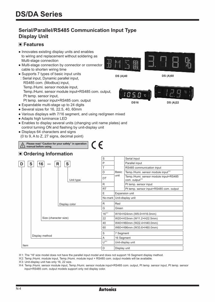
SpecificationsModel
Basic unit DS16- S/T/D D 22- S/P/T/D/R D 40- S/P/T/D/DT/R/RT D 60- S/P/T/D/DT/R/RTExpansion unit DS16- E D 22- E D 40- E D 60- E
Input method
D - S: Serial D - P: Parallel (Dynamic Parallel 1, Dynamic Parallel 2)D - T: RS485 communication (Modbus protocol) DS -RD (T): Temp./Humi. sensor module (THD-RM-S) input (I2C input type)DS -RR (T): Pt temp. sensor input (supports DPt100Ω, JPt 100Ω)※1
Display color Red, Green (selectable by model) Power supply 12-24VDC Allowable voltage range 90 to 110% of rated voltage
Cur
rent
cons
umpt
ion
Red
D -RS/RP/RT/RE Max. 20mA Max. 25mA Max. 55mA Max. 65mA D -RD/RDT/RR/RRT Max. 40mA Max. 40mA Max. 55mA Max. 65mA
Green Max. 15mA Max. 20mA Max. 40mA Max. 45mACharacter size W9×H16mm W11.2×H22.5mm W22.4×H40mm W33.6×H60mm
Max. Clock※2, ※3 Serial input: Max. 2kHz Parallel input: Dynamic Parallel 1: Max. 3kHz, Dynamic Parallel 2: Max. 1.5kHz
Input logic※2 Selectable positive logic (PNP), negative logic (NPN) (change by the function set switch) Input resistance※2 20kΩ Input level※2 High: 4.5-24VDC, Low: 0-1.2VDCDisplay character※4 64 characters and signs (0 to 9, A to Z, 27 signs, decimal point)
Display temp./humi. rangeDS -RD/RDT temperature: -19.9 to 60.0, humidity: 00.0 to 99.9%RHDS -RR/RRT temperature: -50.0 to 400.0 or -58.0 to 752.0
Display accuracyDS -RD/RDT temperature: ±1.0 (room temperature※5), humidity: ±2.0%RH (10 to 90%RH, room temperature※5)DS -RR/RRT: ±0.5% F.S.
Output - RS485 com. output (Modbus RTU)※6
The number of max. multi-stange connections
Serial/RS485 com. input: 24 unitsParallel: Dynamic Parallel 1: 6 units (4-bit), 4 units (6-bit)/ Dynamic Parallel 2: 24 units (6-bit) Temp./Humi. sensor module input (+RS485 com. output): 6 units (3 units for temp. display, 3 units for humidity display, except unit-display unit)Pt temperature sensor input (+RS485 com. output): 4 units (except unit-display unit)
Noise resistance ±500V the square wave noise (pulse width: 1) by the noise simulator
Envir-onment
Ambient temperature -10 to 55, storage: -25 to 65 (for THD-RM-S, -19.9 to 60, storage: -19.9 to 60)Ambient humidity 35 to 85%RH (for THD-RM-S, 0 to 99.9%, storage: 0 to 99.9%)
Acc
esso
ry Basic unit Cap: right/left 1EA Cap: right/left 1EA, Connector: 1EA Connector: 1EA※7
Expansion unit - Ribbon cable: 1EA (50mm) DS -RD/RDT Temp./Humi. sensor module (THD-RM-S)
Protection structure IP40 (front part)Approval (except DS -RD (T))
Weight※8
D -S/P/T/R/RT
Approx. 52g(approx. 12g)
Approx. 58g(approx. 17g)
Approx. 63g(approx. 28g)
Approx. 110g(approx. 60g)
DS -RD/RDT Approx. 168g(approx. 12g)
Approx. 173g(approx. 17g)
Approx. 184g(approx. 28g)
Approx. 216g(approx. 60g)
D - E Approx. 77g(approx. 12g)※9
Approx. 92g(approx. 17g)※9
Approx. 63g(approx. 28g)
Approx. 110g(approx. 60g)
N-6
DS/DA Series
Flat-headscrew driver
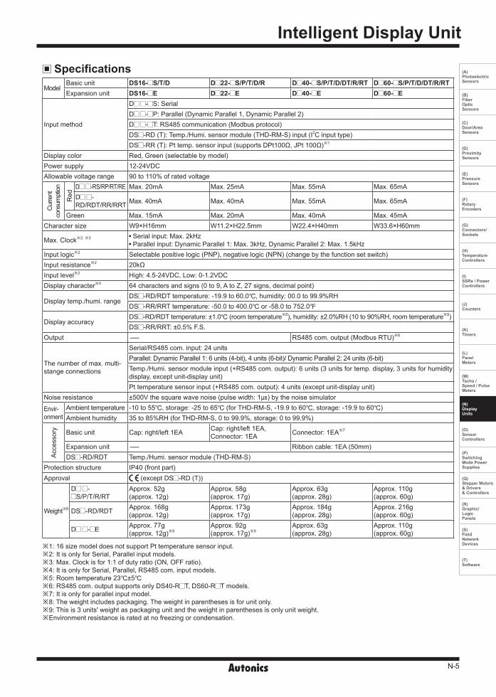
To operate the function set switch of the D 40, D 60 models, you should remove the protection cover. Press the connection parts (4 points) of the protection cover at the top/bottom of the product with a flat-head screwdriver and the protection cover is removed.
Caution: Before removing the protection cover, power must be turned OFF.
Removing Protection Cover
Middlebracket Expansion connector
Unit-display unitExpansion unit
Expansion unit Expansion unit 2
Solderingpad
Cable length: Max. 1m
Expansion unit 1
Solderingpad
Basic unit
Basic unit
Ribbon cable (Figure 1) (Figure 2)
CapCap
DS16/D 22
D 40/D 60
Connect a basic unit, expansion units, a unit-display unit from the left and connect the caps the end of right and left.
The middle bracket (sold separately) helps to protect deflection when connecting over 7 units. Use one middle bracket per 7 units.
The basic unit supplies the power for expansion units and the unit-display unit and DATA input.
Connect expansion connectors of units using a ribbon cable (accessory) as (Figure 1). If the distance between expansion units is far as (Figure 2), you can connect the cable at the soldering pad. To use a soldering pad, remove the protection cover which only expansion units have.
※You can use both the 7 segment display method model and the 16 segment display method model mixed.
Connection Of Units※Tighten it with below 0.8N·m.
Input
Input
100
100
IC
IC20
20
※Input level High: 4.5-24VDC
Low: 0-1.2VDC
5V
Positive logic (PNP) input Negative logic (NPN) input Input Circuit
Connections Temp./Humi. sensor module input model
12345678
12-24VDC
(Brown)VCC(Blue)GND
(White)SDA(Black)SCL
RS485 A (+)RS485 B (-)
Temp./Humi sensor module
+
-
※Shaded terminals are only for the model supporting RS485 communication output (DS40-R T, DS60-R T).
12-24VDC
AB
B'RS485 A (+)RS485 B (-)
+
-
1234567
DPt100Ω, JPt100Ω
Pt temp. sensor input model

N-7
Intelligent Display Unit
(A) Photoelectric Sensors
(B) FiberOpticSensors
(C) Door/AreaSensors
(D) ProximitySensors
(E) PressureSensors
(F) RotaryEncoders
(G) Connectors/Sockets
(H)TemperatureControllers
(I)SSRs / PowerControllers
(J) Counters
(K) Timers
(L) PanelMeters
(M)Tacho /Speed / PulseMeters
(N)DisplayUnits
(O)SensorControllers
(P)SwitchingMode PowerSupplies
(Q)Stepper Motors & Drivers & Controllers
(R)Graphic/LogicPanels
(S)FieldNetworkDevices
(T) Software
SwitchSwitch
FunctionOFF ON
S1 Positive logic (PNP)
Negative logic (NPN) Input logic
S2 Not used Used Zero Blanking
S3 Not used Used Decimal number display※1
S4 8-bit 5-bit※2 Data input bit
Terminal Code Function
1 VCC 12-24VDC
2 GND 0V
3 Data Data input
4 CLOCK CLOCK input
5 LATCH LATCH input
SwitchSwitch
FunctionOFF ON
S1 Positive logic (PNP)
Negative logic (NPN) Input logic
S2 Not used Used Zero Blanking
S3 6-bit 4-bit※1 Data input bit
S4 Dynamic 1 Dynamic 2 Dynamic 1/2 selection
J1 All Zero Blanking※2
※1: The other data except 0 to 9 are blank. ※2: 5-bit data input is compatible with Autonics pulse meter
(MP5W) and panel meter (MT4Y, MT4W).
<Factory default>
<Factory default>
※For the D 22- S, connect the connector to input terminal.
① Expansion connectorUsing for connecting units.Refer to ' Connection of units'.
③ Input terminals
1S2S1
S3
S4
23
4
ON
ON
1S2S1
S3S4
2
34
ON J1
ON
Unit Description And Function SettingOnly the basic unit model has the function set switch and the input terminal.The DS16, D 22 models have them at the side, and the D 40. D 60 models have them at the rear.
Serial input model
Parallel input model
② Function set switch
① Expansion connector Using for connecting units. Refer to ' Connection of units'.
② Function set switch
※1: 4-bit data input is compatible with Autonics pulse meter (MP5Y, MP5W, panel meter (MT4Y, MT4W).
※2: When every number is '0', it becomes All Zero Blanking. E.g.)When displaying 000045 using two basic units, Using All Zero Blanking,
Not using All Zero Blanking
②
③
11
1 1
22
2 2
33
3 3
44
4 4
55
5 5
③
①
①
①
①
②
②
②③
③
DS16- S
D 40- S
D 22- S
D 60- S
③ ③
①
①
③
① ②
②
②
D 22- P
D 40- P D 60- P
Basic unit
Basic unit
Basic unit
Basic unit
②
N-8
DS/DA Series
<Factory default>
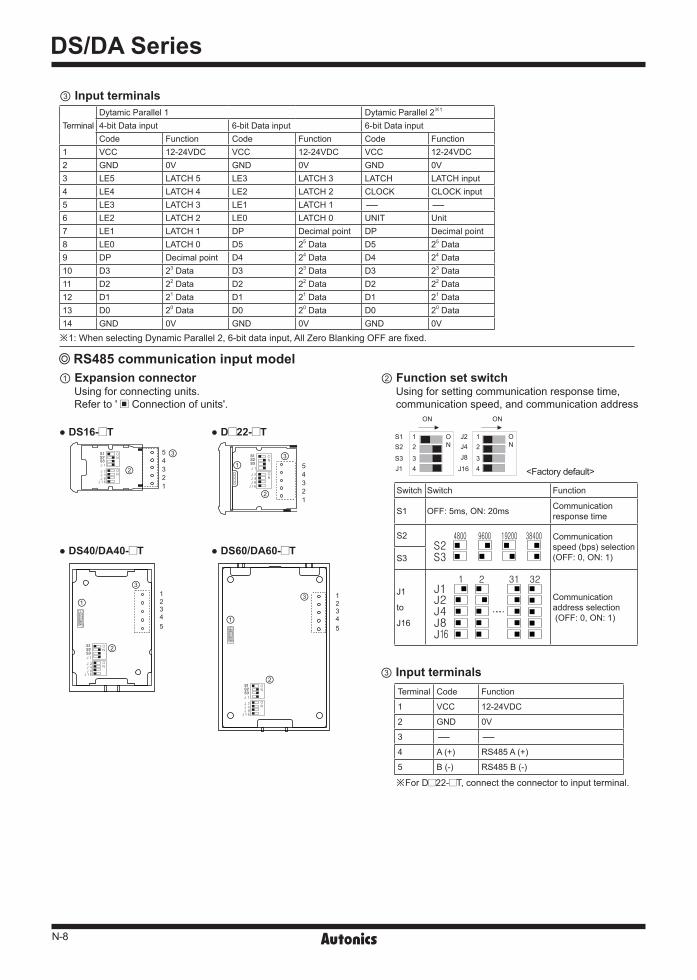
TerminalDytamic Parallel 1 Dytamic Parallel 2※1
4-bit Data input 6-bit Data input 6-bit Data inputCode Function Code Function Code Function
1 VCC 12-24VDC VCC 12-24VDC VCC 12-24VDC 2 GND 0V GND 0V GND 0V 3 LE5 LATCH 5 LE3 LATCH 3 LATCH LATCH input4 LE4 LATCH 4 LE2 LATCH 2 CLOCK CLOCK input5 LE3 LATCH 3 LE1 LATCH 1 - -6 LE2 LATCH 2 LE0 LATCH 0 UNIT Unit7 LE1 LATCH 1 DP Decimal point DP Decimal point8 LE0 LATCH 0 D5 25 Data D5 25 Data9 DP Decimal point D4 24 Data D4 24 Data 10 D3 23 Data D3 23 Data D3 23 Data 11 D2 22 Data D2 22 Data D2 22 Data 12 D1 21 Data D1 21 Data D1 21 Data 13 D0 20 Data D0 20 Data D0 20 Data 14 GND 0V GND 0V GND 0V
※1: When selecting Dynamic Parallel 2, 6-bit data input, All Zero Blanking OFF are fixed.
Terminal Code Function
1 VCC 12-24VDC
2 GND 0V
3 - -
4 A (+) RS485 A (+)
5 B (-) RS485 B (-)
③ Input terminals
RS485 communication input model ② Function set switch
Using for setting communication response time, communication speed, and communication address
※For D 22- T, connect the connector to input terminal.
Switch Switch Function
S1 OFF: 5ms, ON: 20ms Communication response time
S2 Communication speed (bps) selection(OFF: 0, ON: 1)S3
J1
to
J16
Communication address selection (OFF: 0, ON: 1)
1 1S2S1
S3J1
J2J4J8
J16
2 2
3 34 4
ON
ON
ONON
① Expansion connector Using for connecting units.Refer to ' Connection of units'.
12345
12345
①
①
②
②
③
③
DS16- T
DS40/DA40- T
D 22- T
DS60/DA60- T
12345 ③
②
12345
①
②
③
③ Input terminals
N-9
Intelligent Display Unit
(A) Photoelectric Sensors
(B) FiberOpticSensors
(C) Door/AreaSensors
(D) ProximitySensors
(E) PressureSensors
(F) RotaryEncoders
(G) Connectors/Sockets
(H)TemperatureControllers
(I)SSRs / PowerControllers
(J) Counters
(K) Timers
(L) PanelMeters
(M)Tacho /Speed / PulseMeters
(N)DisplayUnits
(O)SensorControllers
(P)SwitchingMode PowerSupplies
(Q)Stepper Motors & Drivers & Controllers
(R)Graphic/LogicPanels
(S)FieldNetworkDevices
(T) Software
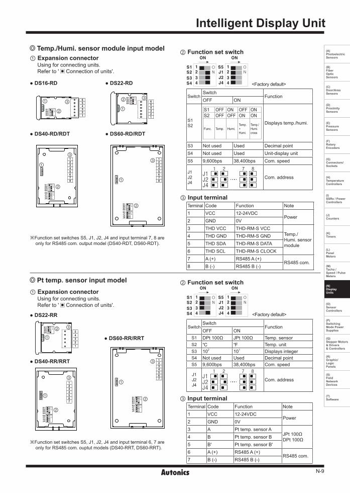
Temp./Humi. sensor module input model
DS16-RD
DS40-RD/RDT
DS22-RD
DS60-RD/RDT
③①
②
654321
S1S2S3S4
③
①
②654321
S1S2S3S4
③
①
②
12345678
S1S2S3S4
S5J1J2J4
③
①
②
12345678
S1S2S3S4
S5J1J2J4
② Function set switch
1 1
S2
S1
S3
S4
S5
J1
J2
J4
2 2
3 3
4 4
ON
ON
ONON
SwitchSwitch
FunctionOFF ON
S1S2
S1 OFF ON OFF ONS2 OFF OFF ON ON
Func. Temp. Humi.Temp.+Humi.
Temp./Humi.cross
Displays temp./humi.
S3 Not used Used Decimal pointS4 Not used Used Unit-display unitS5 9,600bps 38,400bps Com. speed
J1J2J4
Com. address
Terminal Code Function Note1 VCC 12-24VDC
Power2 GND 0V3 THD VCC THD-RM-S VCC
Temp./Humi. sensor module
4 THD GND THD-RM-S GND5 THD SDA THD-RM-S DATA6 THD SCL THD-RM-S CLOCK7 A (+) RS485 A (+)
RS485 com.8 B (-) RS485 B (-)
③ Input terminal
※Function set switches S5, J1, J2, J4 and input terminal 7, 8 are only for RS485 com. output model (DS40-RDT, DS60-RDT).
Pt temp. sensor input model
DS40-RR/RRT
DS22-RR
DS60-RR/RRT
③
①②
5
4
3
2
1
S1S2S3S4
③
①
②S1S2S3S4
S5J1J2J4
1234567
③
①
1234567
②S1S2S3S4
S5J1J2J4
② Function set switch
1 1
S2
S1
S3
S4
S5
J1
J2
J4
2 2
3 3
4 4
ON
ON
ONON
SwitchSwitch
FunctionOFF ON
S1 DPt 100Ω JPt 100Ω Temp. sensorS2 Temp. unitS3 102 101 Displays integerS4 Not used Used Decimal pointS5 9,600bps 38,400bps Com. speed
J1J2J4
Com. address
Terminal Code Function Note1 VCC 12-24VDC
Power2 GND 0V3 A Pt temp. sensor A
JPt 100ΩDPt 100Ω4 B Pt temp. sensor B
5 B' Pt temp. sensor B'6 A (+) RS485 A (+)
RS485 com.7 B (-) RS485 B (-)
③ Input terminal
※Function set switches S5, J1, J2, J4 and input terminal 6, 7 are only for RS485 com. ouptut models (DS40-RRT, DS60-RRT).
① Expansion connector Using for connecting units.Refer to ' Connection of units'.
① Expansion connector Using for connecting units.Refer to ' Connection of units'.
<Factory default>
<Factory default>
N-10
DS/DA Series
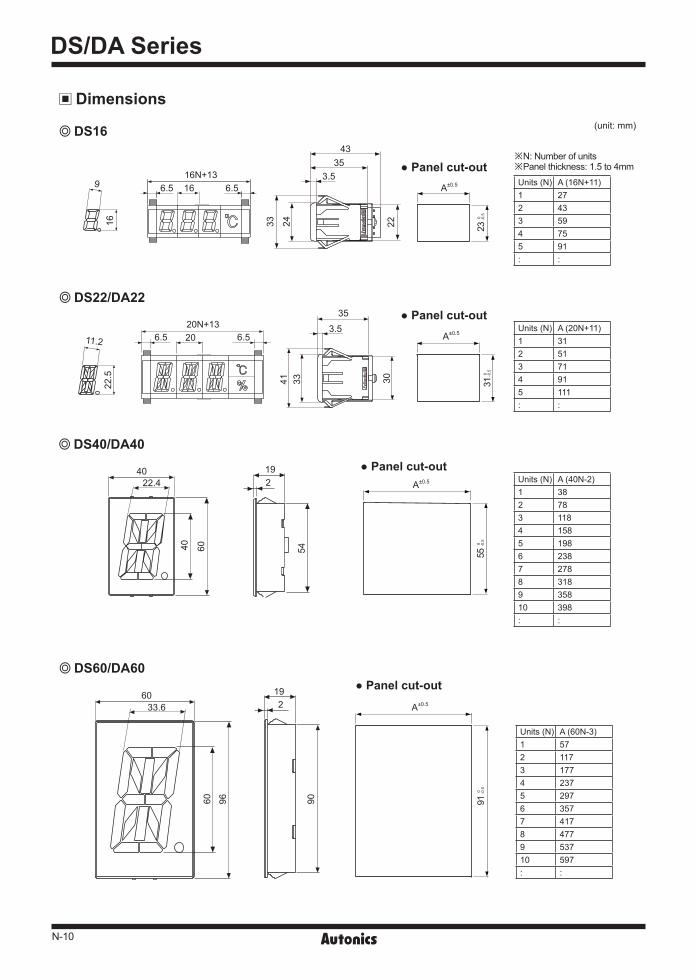
(unit: mm)
Dimensions
A±0.540
22.4 219
40 60 54
Units (N) A (40N-2)1 382 783 1184 1585 1986 2387 2788 3189 35810 398: :
55 0 -0
.5
Panel cut-out
DS40/DA40
DS16
9 6.5 16 6.5
43
A±0.5
353.516N+13
33 24 22
Units (N) A (16N+11)1 272 433 594 755 91: :
Panel cut-out※N: Number of units※Panel thickness: 1.5 to 4mm
23 0 -0
.5
16
11.2 6.5 20 6.5 A±0.5
35
3.520N+13
41 33 30
Units (N) A (20N+11)1 312 513 714 915 111: :
31 0 -0
.5
Panel cut-out DS22/DA22
22.5
6033.6
192
60 96 90
Units (N) A (60N-3)1 572 1173 1774 2375 2976 3577 4178 4779 53710 597: :
A±0.5
91 0 -0
.5
DS60/DA60 Panel cut-out
N-11
Intelligent Display Unit
(A) Photoelectric Sensors
(B) FiberOpticSensors
(C) Door/AreaSensors
(D) ProximitySensors
(E) PressureSensors
(F) RotaryEncoders
(G) Connectors/Sockets
(H)TemperatureControllers
(I)SSRs / PowerControllers
(J) Counters
(K) Timers
(L) PanelMeters
(M)Tacho /Speed / PulseMeters
(N)DisplayUnits
(O)SensorControllers
(P)SwitchingMode PowerSupplies
(Q)Stepper Motors & Drivers & Controllers
(R)Graphic/LogicPanels
(S)FieldNetworkDevices
(T) Software
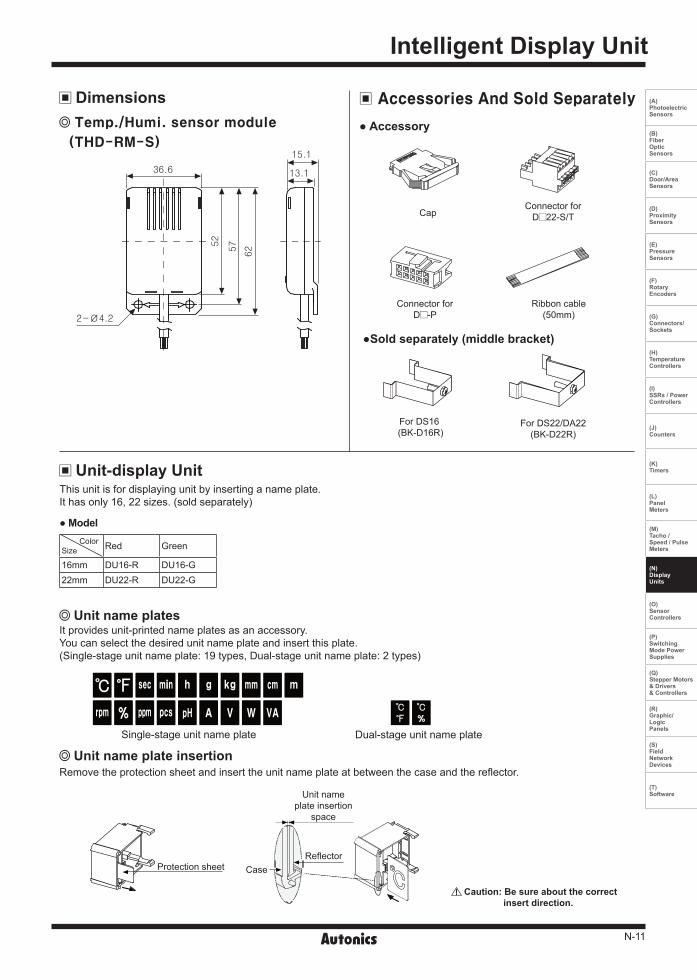
Single-stage unit name plate
Protection sheet CaseReflector
Unit name plate insertion
space
Dual-stage unit name plate
Caution: Be sure about the correct insert direction.
ColorSize Red Green
16mm DU16-R DU16-G22mm DU22-R DU22-G
Model
Unit name plate insertion
This unit is for displaying unit by inserting a name plate.It has only 16, 22 sizes. (sold separately)
It provides unit-printed name plates as an accessory.You can select the desired unit name plate and insert this plate.(Single-stage unit name plate: 19 types, Dual-stage unit name plate: 2 types)
Remove the protection sheet and insert the unit name plate at between the case and the reflector.
Unit-display Unit
Unit name plates
Accessory
Sold separately (middle bracket)
Accessories And Sold Separately
Temp./Humi. sensor module
(THD-RM-S)
36.6 13.1
15.1
625752
2-Ø4.2
Dimensions
CapConnector for
D 22-S/T
Connector for D -P
Ribbon cable(50mm)
For DS16 (BK-D16R)
For DS22/DA22(BK-D22R)
N-12
DS/DA Series
DS Series (7 segment) DA Series (16 segment) DU Series(unit)
Hi 2-bitLow 4-bit
D5 D4 D5 D4 D5 D4 D5 D4 D5 D4 D5 D4 D5 D4 D5 D4 D5 D4D3 D2 D1 D0
L L L H H L H H L L L H H L H H X X
0 G W ] 0 G W ] No unit L L L L
1 H X 1 H X [Upper-Lower OFF L L L H
2 I Y 2 I Y +U p p e r - L o w e r ON L L H L
3 J Z 3 J Z : Upper ON L L H H
4 K -1 ˚ 4 K -1 ; Lower ON L H L L
5 L ( ₩ 5 L ( <U p p e r - L o w e r flashes L H L H
6 M ) H (h) 6 M ) >Upperflashes L H H L
7 N ' I 7 N ' |Lower flashes L H H H
8 O " J 8 O " !
※1
H L L L
9 P ^ K 9 P ^ @ H L L H
A Q . K A Q . # H L H L
B R / N B R / $ H L H H
C S ? O C S ? % H H L L
D T - T D T - & H H L H
E U _ X E U _ H H H L
F V = Blank F V = Blank H H H H
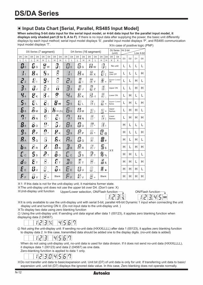
When selecting 5-bit data input for the serial input model, or 4-bit data input for the parallel input model, it displays only shaded part (0 to 9, A to F). If there is no input data after supplying the power, the basic unit differently displays by each input method; serial input model displays ‘S’, parallel input model displays ‘P’, and RS485 communication input model displays ‘T’.
Upper/Lower selection, ON/Flash function ON/Flash function
Input Data Chart [Serial, Parallel, RS485 Input Model]
※1: If this data is not for the unit-display unit, it maintains former state. ※The unit-display unit does not use the upper bit over D4. (Don’t care: X) ※Unit-display unit function
※It is only available to use the unit-display unit with serial 5-bit, parallel 4/6-bit Dynamic 1 input when connecting the unit display unit and turning ON it. (Do not input data to the unit-display unit. )
※To display two data using zero blanking function① Using the unit-display unit: If sending unit data signal after data 1 (00123), it applies zero blanking function when displaying data 2 (04567).
② Not using the unit-display unit: If sending no-unit data (HXXXLLLL) after data 1 (00123), it applies zero blanking function to display data 2. In this case, transmitted data should be added one to the display digits. (no-unit data is added)
When do not using unit-display unit, no-unit data is used for data division. If it does not send no-unit data (HXXXLLLL),it displays data 1 (00123) and data 2 (04567) as one data.Zero-blanking function is applied to data 1 only.
※Do not transfer unit data to basic/expansion unit. Unit bit (D7) of unit data is only for unit. If transferring unit data to basic/expansion unit, unit bit (D7) displays the ignored data value. In this case, Zero blanking does not operate normally.
※In case of positive logic (PNP)

N-13
Intelligent Display Unit
(A) Photoelectric Sensors
(B) FiberOpticSensors
(C) Door/AreaSensors
(D) ProximitySensors
(E) PressureSensors
(F) RotaryEncoders
(G) Connectors/Sockets
(H)TemperatureControllers
(I)SSRs / PowerControllers
(J) Counters
(K) Timers
(L) PanelMeters
(M)Tacho /Speed / PulseMeters
(N)DisplayUnits
(O)SensorControllers
(P)SwitchingMode PowerSupplies
(Q)Stepper Motors & Drivers & Controllers
(R)Graphic/LogicPanels
(S)FieldNetworkDevices
(T) Software
START
START
LATCH
LATCH
SHIFT
SHIFT
0.5ms
0.5ms
Poi
nt
tw
tw
ta
ta
CLOCK
CLOCK
Data
Data Data Data
Data DataMS
B (2
)M
SB
(2)
LSB
(2)
LSB
(2)
MS
B (1
)
MS
B (1
)
LSB
(1)
LSB
(1)
MS
B (0
)
MS
B (0
)LS
B (0
)
LSB
(0)
1-bit Data
1-bit Data
ta: 0.2ms (min.)tw: 025ms (min.)
ta: 0.2ms (min.)tw: 025ms (min.)
※Clock: Max. 2kHz※These are examples for positive logic (PNP).
Caution: The unit-display unit is available only for turning ON. Do not input data to the unit-display unit.
L
L L L L L L L L L L L L L L L L
L L L H
H H H H HX X X
H H HL L L L L L LD4
D4 D4 D4D5 D5 D5D6 D6 D6D7 D7 D7
D4 D4D3
D3 D3 D3
D3 D3D2
D2 D2 D2
D2 D2D1
D1 D1 D1
D1 D1D0
D0 D0 D0
D0 D0
Basic unit
4-bitData
4-bitData
LATCH0 to 5
Point
PointLATCH 0LATCH 1
LATCH 2
LATCH 3LATCH 4LATCH 5
Pw
HLHL HHLL HHHL LLLL LLLL LHHH
t1 t3
※Max. data input speed: 3kHz
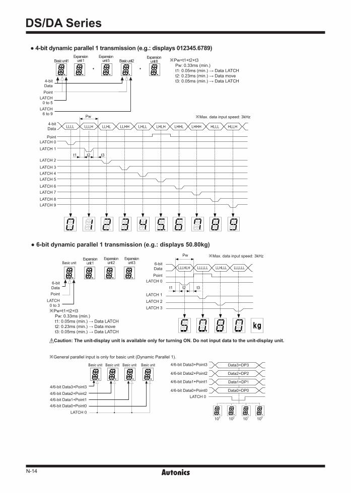
※Pw=t1+t2+t3Pw: 0.33ms (min.)t1: 0.05ms (min.) → Data LATCHt2: 0.23ms (min.) → Data movet3: 0.05ms (min.) → Data LATCH
5-bit serial input (e.g.: displays 12.8)
8-bit serial input (e.g.: displays 25)
Example of unit organization by data input
4-bit dynamic parallel 1 transmission (e.g.: displays ACE007.)
Dynamic Parallel 1
4-bit Connectable 1 basic unit and 5 expansion units (6Digit)E.g.) 10digit organization: (1 basic unit + 5 expansion units)+ (1 basic unit + 3 expansion units)
6-bit Connectable 1 basic unit and 3 expansion units (4Digit)E.g.) 10digit organization: (1 basic unit + 3 expansion units)×2+ (1 basic unit + 1 expansion units)
Dynamic Parallel 2 6-bit Connectable 1 basic unit and 23 expansion units (24Digit)
E.g.) 30digit organization: (1 basic unit + 23 expansion units)+ (1 basic unit + 5 expansion units)
Data Input Method [Serial, Parallel, RS485 Input Model]
Poi
nt
Poi
nt
Poi
nt
Poi
nt
Poi
nt
Uni
t
Uni
t
Uni
t
Serial input model
Parallel input model
t2
Expansion unit 1
Expansion unit 5
N-14
DS/DA Series
4-bit dynamic parallel 1 transmission (e.g.: displays 012345.6789)
Basic unit
Basic unit Basic unit Basic unit Basic unit
6-bitData
6-bitData
LATCH0 to 3
Point
PointLATCH 0
LATCH 0
LATCH 0
103 102 101 100
4/6-bit Data3+Point3
4/6-bit Data3+Point3 Data3+DP3
Data2+DP2
Data1+DP1
Data0+DP04/6-bit Data2+Point2
4/6-bit Data2+Point2
4/6-bit Data1+Point1
4/6-bit Data1+Point1
4/6-bit Data0+Point0
4/6-bit Data0+Point0
LATCH 1LATCH 2LATCH 3
Pw
LLLHLH LLLLLL LLHLLL LLLLLL
t1 t3
※Max. data input speed: 3kHz
※Pw=t1+t2+t3Pw: 0.33ms (min.)t1: 0.05ms (min.) → Data LATCHt2: 0.23ms (min.) → Data movet3: 0.05ms (min.) → Data LATCH
6-bit dynamic parallel 1 transmission (e.g.: displays 50.80kg)
※General parallel input is only for basic unit (Dynamic Parallel 1).
Caution: The unit-display unit is available only for turning ON. Do not input data to the unit-display unit.
Basic unit1 Basic unit2
4-bitData
4-bitData
LATCH0 to 5
LATCH 0
LATCH 1
LATCH 2
LATCH 3LATCH 4LATCH 5
LATCH 6LATCH 7
LATCH 8LATCH 9
LATCH6 to 9
Point
Point
Pw
LLLL LLLH LLHL LLHH LHLL LHLH LHHL LHHH HLLL HLLH
t1 t2 t3
※Max. data input speed: 3kHz
※Pw=t1+t2+t3Pw: 0.33ms (min.)t1: 0.05ms (min.) → Data LATCHt2: 0.23ms (min.) → Data movet3: 0.05ms (min.) → Data LATCH
Expansion unit 8
Expansion unit 2
Expansion unit 3
Expansion unit 1
Expansion unit 5
Expansion unit 1
t2
N-15
Intelligent Display Unit
(A) Photoelectric Sensors
(B) FiberOpticSensors
(C) Door/AreaSensors
(D) ProximitySensors
(E) PressureSensors
(F) RotaryEncoders
(G) Connectors/Sockets
(H)TemperatureControllers
(I)SSRs / PowerControllers
(J) Counters
(K) Timers
(L) PanelMeters
(M)Tacho /Speed / PulseMeters
(N)DisplayUnits
(O)SensorControllers
(P)SwitchingMode PowerSupplies
(Q)Stepper Motors & Drivers & Controllers
(R)Graphic/LogicPanels
(S)FieldNetworkDevices
(T) Software
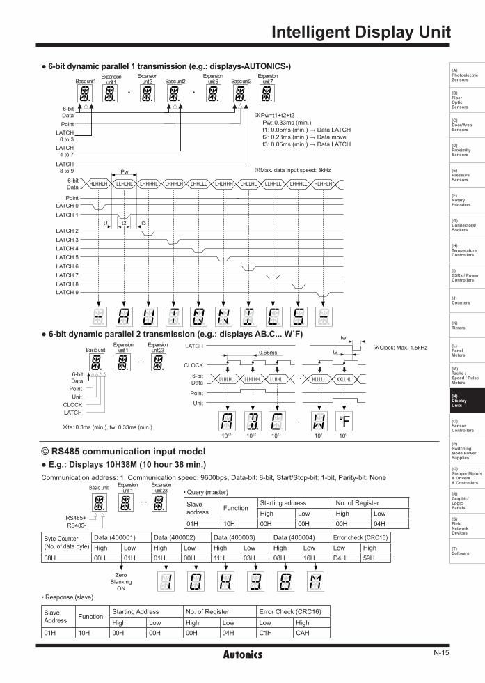
6-bit dynamic parallel 1 transmission (e.g.: displays-AUTONICS-)
Basic unit
RS485+RS485-
Slaveaddress Function
Starting address No. of RegisterHigh Low High Low
01H 10H 00H 00H 00H 04H
E.g.: Displays 10H38M (10 hour 38 min.)Communication address: 1, Communication speed: 9600bps, Data-bit: 8-bit, Start/Stop-bit: 1-bit, Parity-bit: None
• Query (master)
RS485 communication input model
Basic unit1 Basic unit3Basic unit2
6-bitData
6-bitData
LATCH0 to 3
LATCH4 to 7
LATCH 0
LATCH 1
LATCH 2LATCH 3LATCH 4LATCH 5LATCH 6LATCH 7LATCH 8LATCH 9
LATCH8 to 9
Point
Point
Pw
HLHHLH LLHLHL LHHHHL LHHHLH LHHLLL LHLHHH LHLLHL LLHHLL LHHHLL HLHHLH
t1 t3
※Max. data input speed: 3kHz
※Pw=t1+t2+t3Pw: 0.33ms (min.)t1: 0.05ms (min.) → Data LATCHt2: 0.23ms (min.) → Data movet3: 0.05ms (min.) → Data LATCH
Expansion unit 1
Expansion unit 3
Expansion unit 6
Expansion unit 7
Basic unitExpansion
unit 23
6-bitData
6-bitData
PointPointUnitUnitCLOCK
CLOCK
LATCH
LATCH0.66ms
tw
ta
1023 1022 1021 101 100
LLHLHL LLHLHH LLHHLL HLLLLL XXLLHL
※Clock: Max. 1.5kHz
※ta: 0.3ms (min.), tw: 0.33ms (min.)
6-bit dynamic parallel 2 transmission (e.g.: displays AB.C... W˚F)Expansion
unit 1
Expansion unit 1
Expansion unit 23
Byte Counter(No. of data byte)
Data (400001) Data (400002) Data (400003) Data (400004) Error check (CRC16)High Low High Low High Low High Low Low High
08H 00H 01H 01H 00H 11H 03H 08H 16H D4H 59H
SlaveAddress Function
Starting Address No. of Register Error Check (CRC16)
High Low High Low Low High01H 10H 00H 00H 00H 04H C1H CAH
• Response (slave)
ZeroBlanking
ON
t2
N-16
DS/DA Series
Temp./Humi. sensor module input model
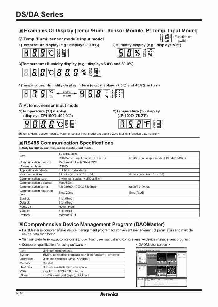
Pt temp. sensor input model
1)Temperature display (e.g.: displays -19.9) 2)Humidity display (e.g.: displays 50%)
3)Temperature+Humidity display (e.g.: displays 6.0 and 80.0%)
4)Temperature, Humidity display in turn (e.g.: displays -7.5 and 45.8% in turn)
S1S2S3S4
S1S2S3S4
S1S2S3S4
1) Temperature () display (displays DPt100Ω, 400.0)
2) Temperature () display (JPt100Ω, 75.2)
S1S2S3S4
S1S2S3S4
※Temp./Humi. sensor module, Pt temp. sensor input model are applied Zero Blanking function automatically.
Examples Of Display [Temp./Humi. Sensor Module, Pt Temp. Input Model]
2 sec. S1S2S3S4
※Only for RS485 communication input/output model.
ItemSpecificationsRS485 com. input model (D - T) RS485 com. output model (DS -RDT/RRT)
Communication protocol Modbus RTU with 16-bit CRC Connection type RS485 Application standards EIA RS485 standards Max. connections 31 units (address: 01 to 32) 8 units (address: 01 to 08)Communication type 2-wire half duplex (Half DuplE.g.) Communication distance Max. 800m Communication speed 4800/9600 /19200/38400bps 9600/38400bps Communication response time 5ms, 20ms 5ms (fixed)
Start bit 1-bit (fixed) Data bit 8-bit (fixed) Parity bit None (fixed) Stop bit 1-bit (fixed) Protocol Modbus RTU
: Function set switch
S1S2S3S4
in turn
RS485 Communication Specifications
Comprehensive Device Management Program (DAQMaster) DAQMaster is comprehensive device management program for convenient management of parameters and multiple device data monitoring.
Visit our website (www.autonics.com) to download user manual and comprehensive device management program.< DAQMaster screen >< Computer specification for using software >
Item Minimum requirementsSystem IBM PC compatible computer with Intel Pentium Ⅲ or aboveOperations Microsoft Windows 98/NT/XP/Vista/7Memory 256MB+Hard disk 1GB+ of available hard disk spaceVGA Resolution: 1024×768 or higherOthers RS-232 serial port (9-pin), USB port

N-17
Intelligent Display Unit
(A) Photoelectric Sensors
(B) FiberOpticSensors
(C) Door/AreaSensors
(D) ProximitySensors
(E) PressureSensors
(F) RotaryEncoders
(G) Connectors/Sockets
(H)TemperatureControllers
(I)SSRs / PowerControllers
(J) Counters
(K) Timers
(L) PanelMeters
(M)Tacho /Speed / PulseMeters
(N)DisplayUnits
(O)SensorControllers
(P)SwitchingMode PowerSupplies
(Q)Stepper Motors & Drivers & Controllers
(R)Graphic/LogicPanels
(S)FieldNetworkDevices
(T) Software
USB B type
B (-)
B (-)
ON OFF
A (+)
A (+)
A (+) B (-) A (+) B (-) A (+) B (-)
Terminating resistance (100 to 120Ω)
※It is only for the RS485 communication input model.
RS485DEVICE
#1
RS485DEVICE
#2
RS485DEVICE
#30
RS485DEVICE
#31
Computer
USB RS485
Application of system organization
※It is recommended to use Autonics communication converter; SCM-US48I (USB to RS485 converter, sold separately), SCM-38I (RS232C to RS485 converter, sold separately). Please use twisted pair wire for RS485 communication.
Communication Setting
Modbus Address Mapping Data format
Product information
Display data
No (Address) Function R/W Parameter DescriptionFactory default NoteD - T DS -RDT/RRT D - T DS -RDT/RRT
300001 to 300100 04 R Reserved300101 (0064) 04 R - Product number H - -300102 (0065) 04 R - Product number L - -300103 (0066) 04 R - Hardware version - -300104 (0067) 04 R - Software version - -300105 (0068) 04 R - Model name 1 'DS'
DS (A)xx-xT DSxx-RDTDSxx-RRT
300106 (0069) 04 R - Model name 2 ' (A' 'xx'300107 (006A) 04 R - Model name 3 ')x' '-R'300108 (006B) 04 R - Model name 4 'x-' 'DT' or 'RT'300109 (006C) 04 R - Model name 5 'xT' 0300110 (006D) to 300114 (0071) 04 R - Model name 6 to 10 0 -
No (Address) Function R/W Parameter Parameter name Description Set range Factory default400001 (0000) 03/06/16 R/W - Zero Blanking Zero Blanking ON/OFF set 0: OFF, 1: ON 0400002 (0001) 03/06/16 R/W - Digit 1, 2 1, 2 display data
Refer to Input data chart
0400003 (0002) 03/06/16 R/W - Digit 3, 4 3, 4 display data 0400004 (0003) 03/06/16 R/W - Digit 5, 6 5, 6 display data 0400005 (0004) 03/06/16 R/W - Digit 7, 8 7, 8 display data 0400006 (0005) 03/06/16 R/W - Digit 9, 10 9, 10 display data 0400007 (0006) 03/06/16 R/W - Digit 11, 12 11, 12 display data 0400008 (0007) 03/06/16 R/W - Digit 13, 14 13, 14 display data 0400009 (0008) 03/06/16 R/W - Digit 15, 16 15, 16 display data 04000010 (0009) 03/06/16 R/W - Digit 17, 18 17, 18 display data 04000011 (000A) 03/06/16 R/W - Digit 19, 20 19, 20 display data 04000012 (000B) 03/06/16 R/W - Digit 21, 22 21, 22 display data 04000013 (000C) 03/06/16 R/W - Digit 23, 24 23, 24 display data 04000014 to 4000050 03/06/16 R/W Reserved
※DOT, unit are displayed at 'H'.Unit DOT Data
Digit 1, 3, 5, ...23 data Digit 2, 4, 6, ...24 dataD7 D6 D5 D4 D3 D2 D1 D0 D7 D6 D5 D4 D3 D2 D1 D0
Monitoring data
No (Address) Function R/W ParameterDescription
Factory default NoteDS -RDT DS -RRT
301001 (03E8) 04 R - Temp. (-199 to 600) Temp. (-500 to 4000) - Data of ×10301002 (03E9) 04 R - Humi. (0 to 999) Temp. (-580 to 7520) - Data of ×10301003 to 301100 04 R - Reserved
※Supports only temp./humi. module input+RS485 com. output (DS -RDT), Pt temp. input+RS485 com. output (DS -RRT) models.
※Supports only RS485 com. input (D - T)model.
N-18
DS/DA Series
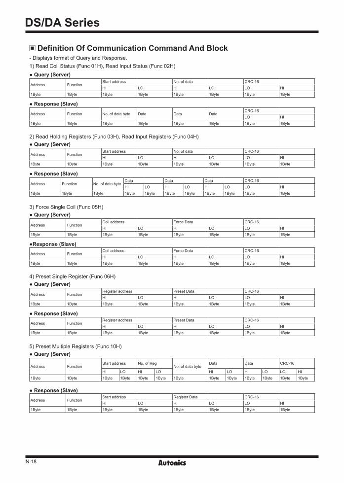
- Displays format of Query and Response.1) Read Coil Status (Func 01H), Read Input Status (Func 02H)
2) Read Holding Registers (Func 03H), Read Input Registers (Func 04H)
3) Force Single Coil (Func 05H)
4) Preset Single Register (Func 06H)
5) Preset Multiple Registers (Func 10H)
Query (Server)
Response (Slave)
Query (Server)
Query (Server)
Query (Server)
Query (Server)
Response (Slave)
Response (Slave)
Response (Slave)
Response (Slave)
Address FunctionStart address No. of data CRC-16 HI LO HI LO LO HI
1Byte 1Byte 1Byte 1Byte 1Byte 1Byte 1Byte 1Byte
Address Function No. of data byte Data Data DataCRC-16 LO HI
1Byte 1Byte 1Byte 1Byte 1Byte 1Byte 1Byte 1Byte
Address FunctionStart address No. of data CRC-16 HI LO HI LO LO HI
1Byte 1Byte 1Byte 1Byte 1Byte 1Byte 1Byte 1Byte
Address FunctionCoil address Force Data CRC-16 HI LO HI LO LO HI
1Byte 1Byte 1Byte 1Byte 1Byte 1Byte 1Byte 1Byte
Address Function No. of data byteData Data Data CRC-16 HI LO HI LO HI LO LO HI
1Byte 1Byte 1Byte 1Byte 1Byte 1Byte 1Byte 1Byte 1Byte 1Byte 1Byte
Address FunctionCoil address Force Data CRC-16 HI LO HI LO LO HI
1Byte 1Byte 1Byte 1Byte 1Byte 1Byte 1Byte 1Byte
Address FunctionRegister address Preset Data CRC-16 HI LO HI LO LO HI
1Byte 1Byte 1Byte 1Byte 1Byte 1Byte 1Byte 1Byte
Address FunctionStart address No. of Reg
No. of data byteData Data CRC-16
HI LO HI LO HI LO HI LO LO HI1Byte 1Byte 1Byte 1Byte 1Byte 1Byte 1Byte 1Byte 1Byte 1Byte 1Byte 1Byte 1Byte
Address FunctionRegister address Preset Data CRC-16 HI LO HI LO LO HI
1Byte 1Byte 1Byte 1Byte 1Byte 1Byte 1Byte 1Byte
Address FunctionStart address Register Data CRC-16 HI LO HI LO LO HI
1Byte 1Byte 1Byte 1Byte 1Byte 1Byte 1Byte 1Byte
Definition Of Communication Command And Block
N-19
Intelligent Display Unit
(A) Photoelectric Sensors
(B) FiberOpticSensors
(C) Door/AreaSensors
(D) ProximitySensors
(E) PressureSensors
(F) RotaryEncoders
(G) Connectors/Sockets
(H)TemperatureControllers
(I)SSRs / PowerControllers
(J) Counters
(K) Timers
(L) PanelMeters
(M)Tacho /Speed / PulseMeters
(N)DisplayUnits
(O)SensorControllers
(P)SwitchingMode PowerSupplies
(Q)Stepper Motors & Drivers & Controllers
(R)Graphic/LogicPanels
(S)FieldNetworkDevices
(T) Software
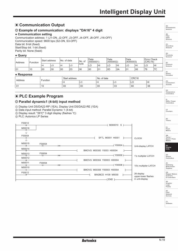
Example of communication: displays "DA16" 4 digit
Parallel dynamic1 (4-bit) input method
Query
Response
Communication settingCommunication address: 1 (J1-ON, J2-OFF, J3-OFF, J4-OFF, J8-OFF, J16-OFF)Communication speed: 9600 bps (S2-ON, S3-OFF)Data bit: 8-bit (fixed)Start/Stop bit: 1-bit (fixed)Parity bit: None (fixed)
① Display Unit DS/DA22-RP (1EA), Display Unit DS/DA22-RE (1EA)② Data input method: Parallel Dynamic 1 (4-bit) ③ Display result: "26" 3 digit display (flashes )④ PLC: Autonics LP Series
Address FunctionStart address No. of data No. of
byte
Data(4000001)
Data(4000002)
Data(4000003)
Error Check(CRC16)
HI LO HI LO LO HI LO HI LO HI LO HI01 10 00 00 00 03 06 00 01 0D 0A 01 06 78 7C
Address FunctionStart address No. of data CRC16HI LO HI LO LO HI
01 10 00 00 00 03 80 08
Communication Output
PLC Example Program
F00012
M00016
M00015
M00014
M00013
M00012
M00011
M00010
F00054
F00012
F00054
F00054
F00054
( Y0000A )
( Y00009 )
[ END ]
[ SFTL M0001 H0001 ]
[ BIN2BCD H109 M0030 ]
CLOCK
Unit-display LATCH
1's multiplier LATCH
10's multiplier LATCH
26 displayupper-lower flashes in unit-display
( M000010 S )
[ BMOVG M00300 Y0003 H00004 ]
( Y00008 )
[ BMOVG M00304 Y00003 H00004 ]
[ BMOVG M00308 Y00003 H00004 ]

N-20
DS/DA Series
Serial (5-bit) input method① Display Unit DS/DA22-RP (1EA) Display Unit DS/DA22-RE (1EA)② Data input method: Serial (5-bit)③ Display result: "26" Display (flashes )④ PLC: Autonics LP Series
M00001
M00003
M00005
M00007
M00009
M0000B
M0000D
M0000F
M00011
M00013
M00015
M00017
M00019
M0001B
M0001D
M00054
M00003
M0000C
M00016
M00005
M0000E
M00018
M00032
M0002B
M0002A
M00029
M00028
M00031
M00027
M00026
M00025
M00024
M00030
M00023
M00022
M00021
M00020
M00007
M00010
M0001A
M00009
M00012
M0001C
M00032
F00054
F00012
M0001F
M00001
M00000
M00002
M00004
M00006
M00008
M0000A
M0000C
M0000E
M00010
M00012
M00014
M00016
M00018
M0001A
M0001C
M0001E
M0001A
M00014
F00054
F000010
Y00001
Y00000
Y00002
END
DMOV H00000001 M0000
DROL M0000 H0001
BIN2BCD H0109 M0002
Point
LATCH
Data
CLOCK
2.6 displayupper-lower flahses in unit-display
Caution For Using1. This unit must be mounted on the panel. 2. This is non-insulated product. Use insulated power for power supply. 3. For using temp./humi. sensor module input, Pt temp. sensor input model, you must wire 3-wire. To extend the wire, the thickness and
length of 3 wires should be same. If the resistance are different, temperature error occurs. 4. For temp./humi. sensor module input, Pt temp. sensor input, if input value is out of the range, each display unit displays Error message.
When it is under min. input value, a unit displays 'L'. When it is over max. input value, a unit displays 'H'. 5. For temp./humi. sensor module input, Pt temp. sensor input model, if temp./humi. sensor module or Pt temp. sensor is not connected, it
displays 'OP (using 2 units)' or 'OPN (using 3 units)'.6. Input signal line①Shorten the cable distance between the external device and this product. ②Use shield cable when input wiring is long.③Wire the input signal line separately from the power line.7. Dielectric or insulation resistance test when this unit is installed in the control panel. ①Separate the unit from the control panel. ②Short circuit all terminals of the unit.8. Do not use this unit at below places.① Place where there are severe vibration or impact. ②Place where strong alkalis or acids are used.③Place where there are direct ray of the sun ④Place where strong magnetic field or electric noise are generated9. Installation environment① It shall be used indoor ②Altitude Max. 2,000m③Pollution Degree 2 ④Installation Category I