Embed Size (px)
Citation preview
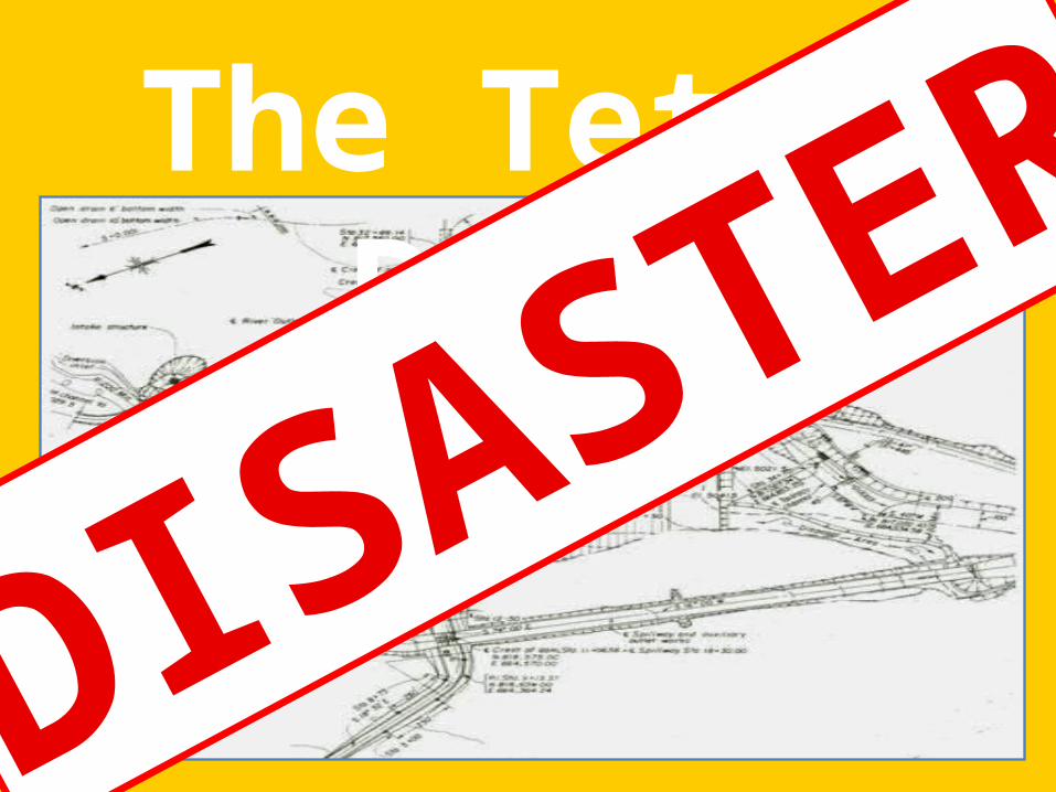
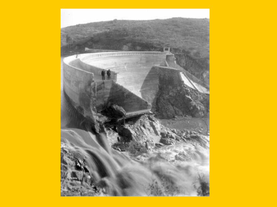
The Teton Dam
DISASTER
3 Easy Steps

STEP 1: SITE SELECTION

Select Area with Unsuitable Rock Types
•8 sites investigated.
•100 borings were taken at the site
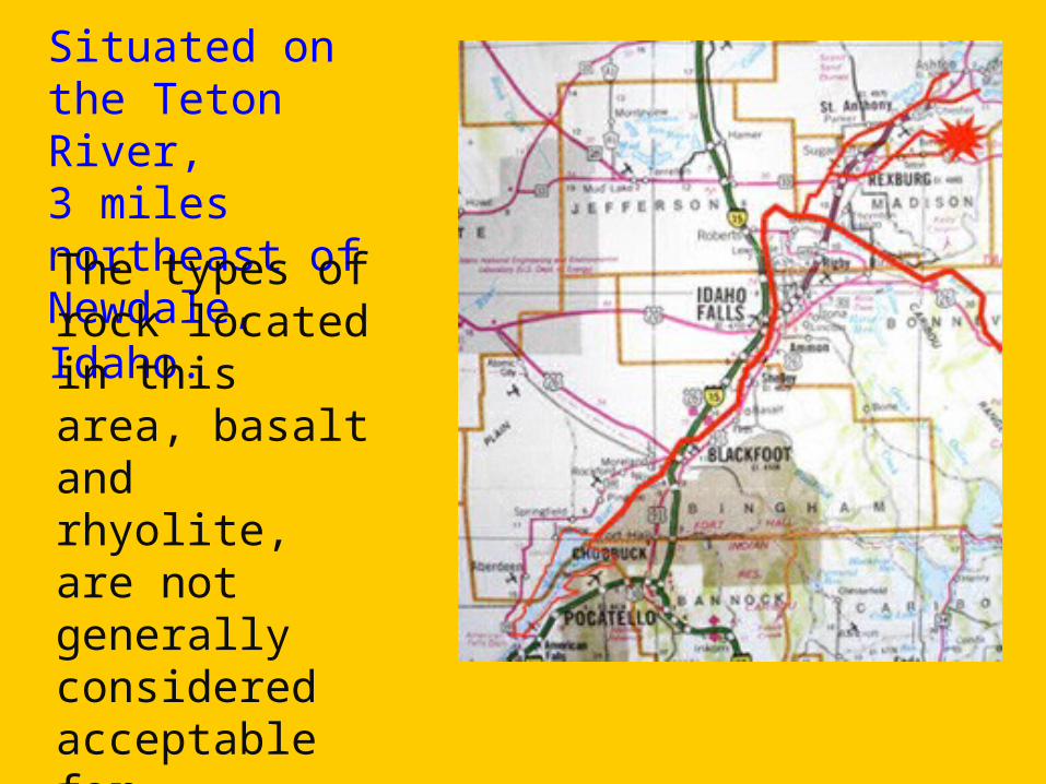
Situated on the Teton River, 3 miles northeast of Newdale, Idaho. The types of rock located in this area, basalt and rhyolite, are not generally considered acceptable for structural foundations.

“highly permeable and moderately to intensely jointed”
Fissures had to be drilled and grouted to stabilize the underlying ground. The dam itself was constructed in five layers with each of a different permeability and structural significance, the main components of these layers were clay, silt and gravel.

STEP 2: DESIGN CHOICES
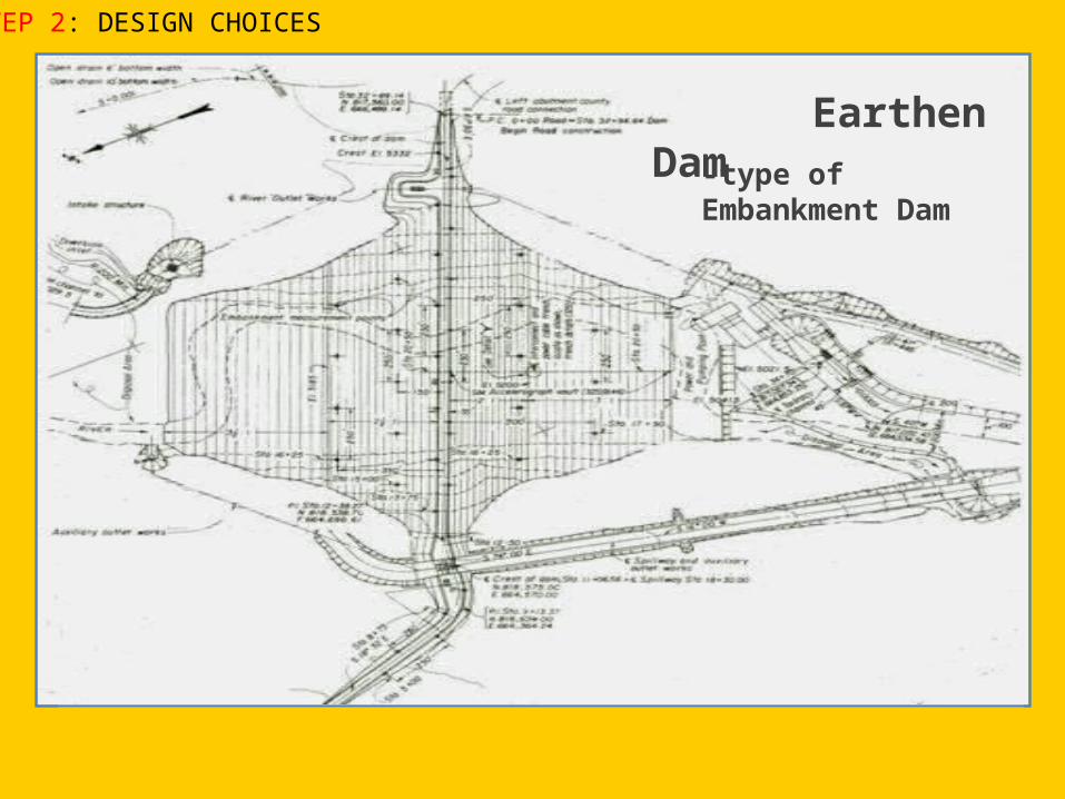
Earthen Dam-type of Embankment Dam
STEP 2: DESIGN CHOICES
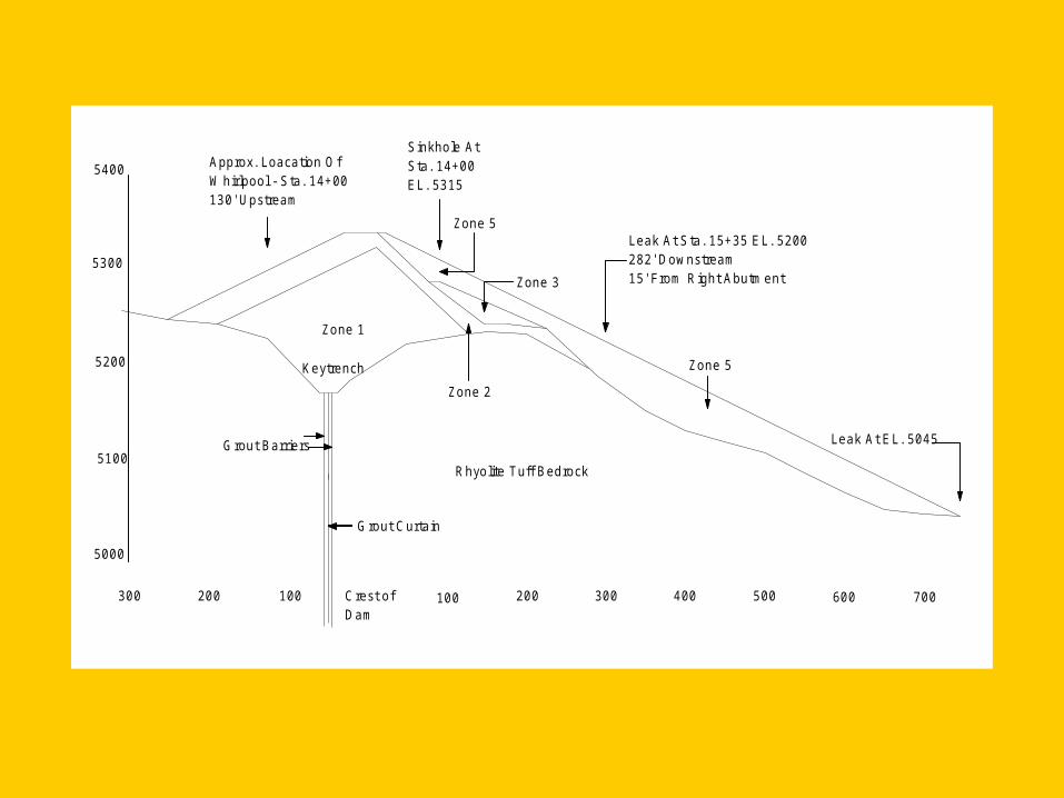
200300 100 Crest ofDam
100 200 300 400 500 600 700
5000
5100
5200
5300
5400 Approx. Loacation OfWhirlpool - Sta. 14+00130' Upstream
Sinkhole AtSta. 14+00EL. 5315
Zone 5
Zone 3
Zone 2
Zone 1
Keytrench
Grout Barriers
Grout Curtain
Rhyolite Tuff Bedrock
Leak At Sta. 15+35 EL. 5200282' Downstream15' From Right Abutment
Zone 5
Leak At EL. 5045
Condition favorable for erosion and piping existed in Zone 1, where the primary materials were highly erodible silts. Wherever this material was subject to flowing water it could be attacked and washed away.
This contact could have occurred in 3 different possible ways.
• Seepage through the material could have caused backward erosion. This was determined not to play a major role in the failure since this process occurs very slowly.
• Second, erosion by direct contact could have occurred where water was in contact with open joints and
• thirdly, where there was direct contact through cracks in the fill itself. It
was determined that these last two were possible and were probably occurring simultaneously (Independent Panel, 1976).

STEP 3: CONSTRUCTION
TECHNIQUE
Part of the Dam was still under construction when
begun to be filled.
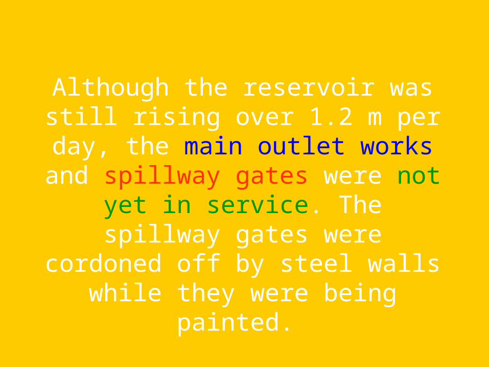
Although the reservoir was still rising over 1.2 m per day, the main outlet works and spillway gates were not yet in service. The spillway gates were cordoned off by steel walls while they were being painted.
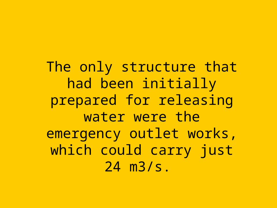
The only structure that had been initially prepared for releasing water were the
emergency outlet works, which could carry just 24 m3/s.
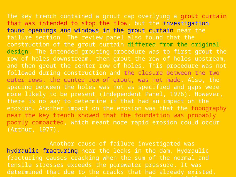
The key trench contained a grout cap overlying a grout curtain that was intended to stop the flow, but the investigation found openings and windows in the grout curtain near the failure section. The review panel also found that the construction of the grout curtain differed from the original design. The intended grouting procedure was to first grout the row of holes downstream, then grout the row of holes upstream, and then grout the center row of holes. This procedure was not followed during construction and the closure between the two outer rows, the center row of grout, was not made. Also, the spacing between the holes was not as specified and gaps were more likely to be present (Independent Panel, 1976). However, there is no way to determine if that had an impact on the erosion. Another impact on the erosion was that the topography near the key trench showed that the foundation was probably poorly compacted, which meant more rapid erosion could occur (Arthur, 1977).
Another cause of failure investigated was hydraulic fracturing near the leaks in the dam. Hydraulic fracturing causes cracking when the sum of the normal and tensile stresses exceeds the porewater pressure. It was determined that due to the cracks that had already existed, the pressure beneath the key trench was less than full reservoir pressure. In other words, due to the fact that the grout curtain was not fully effective, the failure was probably not due to hydraulic fracturing. However, hydraulic fracturing may have been a factor in the initial breaching of the key trench fill (Independent Panel, 1976).

200300 100 Crest ofDam
100 200 300 400 500 600 700
5000
5100
5200
5300
5400 Approx. Loacation OfWhirlpool - Sta. 14+00130' Upstream
Sinkhole AtSta. 14+00EL. 5315
Zone 5
Zone 3
Zone 2
Zone 1
Keytrench
Grout Barriers
Grout Curtain
Rhyolite Tuff Bedrock
Leak At Sta. 15+35 EL. 5200282' Downstream15' From Right Abutment
Zone 5
Leak At EL. 5045

“too much was expected of the grout curtain”
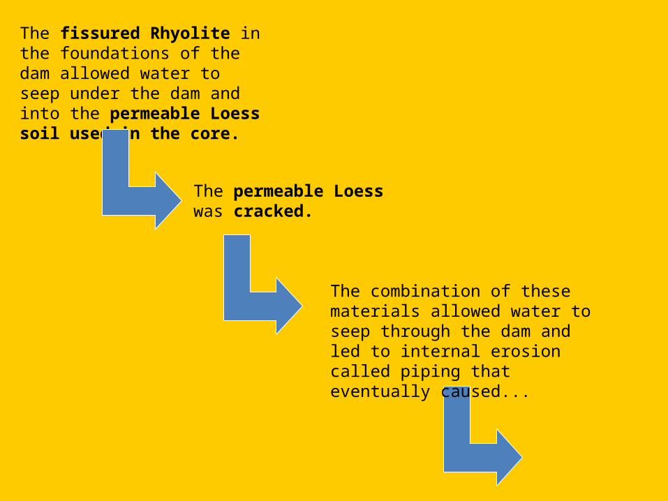
The fissured Rhyolite in the foundations of the dam allowed water to seep under the dam and into the permeable Loess soil used in the core.
The permeable Loess was cracked.
The combination of these materials allowed water to seep through the dam and led to internal erosion called piping that eventually caused...