Embed Size (px)
Citation preview

AMBIENT VIBRATION 3 Feedback from Monitoring to Bridge Design
1
3 FEEDBACK FROM MONITORING TO BRIDGE DESIGN
Structural health monitoring has become widely accepted in bridge management. The methodologies have been considerably developed over the past ten years and reached a certain maturity. Many lessons have been learned from the monitoring activities. This paper highlights the lessons learned over time, which have relevance to bridge design.
3.1 Economic Background
Our transportation infrastructure is aging. Bridges are an essential asset of our economy. Reference is made to the situation in the United States, where within the network of the Federal Highway Agency (FHWA) 590 000 bridges are serving, out of which 160 000 are rated deficient when the traditional methodology is applied. Replacement costs of seven billion US$ annually over 20 years are estimated to achieve a perfect upgrade. In order to avoid such costly situations, the lessons learned with relevance for design should be considered in nowadays bridge design processes. Another drastic example is a bridge built in Austria in 1978, following the minimisation principle of construction costs, at 8.5 million €. Within 25 years a total of 19.5 million € had to be invested into retrofit measures. With consideration of lifecycle cost approaches such situations have to be avoided in future.
3.2 Lessons Learned
The following is a collection of lessons learned from monitoring of over 400 bridge structures since 1997. The structures monitored are mainly situated in central Europe and represent the typical design for this region. Nevertheless most of these lessons can be extended to structures worldwide.
3.2.1 Conservative Design
The monitoring of over 400 bridges clearly shows different behaviour of structures designed following different philosophies. Bridges designed conservatively are not affected by dynamic phenomena that generate concern or trigger damage. Bridges with design focus on economy very often do not have any reserves to cover the extraordinary loadings that appear in reality. The difference in dynamics becomes obvious in the following Figure 3.1 and Figure 3.2. Conservative bridges show a high system damping with distinct characteristics. Economic designs very often come close to areas where resonance appears. This resonance might be a very local and limited effect, but over time it leads to damage in structures.

2 AMBIENT VIBRATION 3 Feedback from Monitoring to Bridge Design
Figure 3.1 Spectrum of a sound bridge (left) and spectrum of a damaged bridge (right)
From bridge management we know that an additional investment in 10% higher quality makes a difference of over 200% of costs over the lifecycle of a bridge of 100 years. Drastic examples experienced are a bridge composed of single span I-girders, designed to the limit, which has consumed 220% of the investment costs in retrofit over a period of 25 years. The opposite is the resistance of a duly designed box girder bridge that survives a displacement of a single pier of 110 cm that could be retrofitted at reasonable costs.
Figure 3.2 Resistant box girder (left) and costly I-girders (right)
3.2.2 External vs. Internal Pre-stressing
Damages found on grouted internal cables triggered a dramatic change of design philosophy. Some countries, like Germany, specified that new bridges have to be built using external cables only. This is for the purpose of inspectability and eventual replacement. The experience made while testing 30 bridges built in the late nineteen-fifties and early sixties showed that only in one of the structures damages of the cables were found. In all other bridges, where damages were suspected, no evidence of corrosion or wire breaks has been detected. The only damaged bridge also has been far away from malfunction. On the other hand the bridges with external pre-stressing often show cracks in the anchoring parts and are often unequally stressed. The best results have been received on bridges, where grouted tendons embedded in concrete in combination with external cables has been chosen.
3.2.3 Influence of Temperature
The design codes for bridges provide clear instruction how to consider the temperature effect in bridge design. These instructions normally give a high and a low temperature to be considered and eventually

AMBIENT VIBRATION 3 Feedback from Monitoring to Bridge Design
3
a temperature gradient between bottom and top of a structure. No reference is made to the type of bridge or the material used. Monitoring provides the chance to exactly record the actual effects of temperature on structures. The lessons learned are actually easy to accept:
Slender structures react very close to the provisions of the codes
Stiff structures very often deviate considerably from the expected stress distribution
The temperature gradients actually recorded on stiff structures by far exceed the values of the design
Temperature load cases can be the decisive load cases
Temperature changes do not trigger a linear behaviour. Below five degrees Celsius a clear stiffening effect is recorded.
The stiffness of concrete bridges depends on temperature. The relation is given in Figure 3.3, which shows an almost bi-linear condition measured on a classical post-tensioned concrete box girder bridge. This has to be considered in the interpretation of monitoring results.
Figure 3.3 1st eigenfrequency vs. wearing surface temperature [1] and 2nd eigenfrequency vs. deck soffit temperature [1]
Steel bridges show quick reactions on changing temperatures. The records of a 5 m high steel box girder are shown in picture Figure 3.4. There is a difference between heating or cooling periods. The sensors represent the outside temperature and the inside temperature on the bottom slab and on the deck slab. The patterns shown here are representative.

4 AMBIENT VIBRATION 3 Feedback from Monitoring to Bridge Design
Figure 3.4 Representative temperature sensor records and longitudinal displacement of the steel bridges’ abutment
Temperature changes in the annual cycle are rather homogeneous. Figure 3.5 shows the behaviour of a concrete mass supported on bridge bearings in a railway tunnel. There is no influence of sunshine. Temperature conditions of the surrounding soil are rather stable, but the trains transport air from outside through the tunnel. The graph shows how homogeneous the structure behaves over the years. The maxima and minima values measured are actually higher than expected. Looking at a concrete bridge (refer to Figure 3.6), where concrete is used in the shape of a box girder with cantilever arms, shows also a rather homogeneous cycle. The maximum and minimum temperatures according to the

AMBIENT VIBRATION 3 Feedback from Monitoring to Bridge Design
5
codes are never reached. The structure reacts moderate to warming or cooling. No clear daily cycle can be isolated.
Figure 3.5 Long-run-behaviour of a concrete mass supported on bridge bearings in a railway tunnel
Figure 3.6 Variation of web temperature of the z-24 bridge observed over a period of one year [2]
A typical steel structure shows a rather violent reaction on temperature changes. The reaction is quite quick and produces strain in the system. This might be because of bearing friction, which is released suddenly causing a displacement of the structure. This effect can be particular harmful to the expansion joints, but also to the bearing. Particular bridges which are not straight in plan might introduce exceptional forces into weak axes of the outfitting.

6 AMBIENT VIBRATION 3 Feedback from Monitoring to Bridge Design
Figure 3.7 Temperature conditions inside the steel-box girder at the Europa Bridge of the Brenner Motorway
The consequence of these experiences should be an individual application of temperature loads depending on the type of the structures and conditions they have to bear. The following implications might be considered:
To increase the loads from differential temperatures in stiff structures
To increase the temperature range considered in steel structures
To look at effects of quick temperature changes on the global behaviour
3.2.4 Displacement
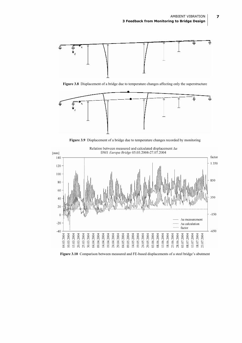
Bridges are flexible and displace under various loads. Displacements are calculated using structural models or finite element calculations. These models very often do not reflect reality. A typical case is the displacement of a certain steel bridge due to temperature changes, which are shown in Figure 3.8. Contrary to that the monitoring results provided displacements according to Figure 3.9 and Figure 3.10. Especially the latter demonstrates the fact, that the displacements of this steel bridge’s abutment are approximately twice as much as those obtained from theoretical, linear elastic calculations. The difference is mainly related to the following facts:
The stiffness of the columns very much depends on the degree of fixation of the pier in the foundation
Bearings do not show a linear behaviour all the times and rather tend to be stiff until a certain minimum force has been reached
A certain stress limit has to be reached before restoring forces are activated, particular when elastomeric bearings are provided
AMBIENT VIBRATION 3 Feedback from Monitoring to Bridge Design
7
Figure 3.8 Displacement of a bridge due to temperature changes affecting only the superstructure
Figure 3.9 Displacement of a bridge due to temperature changes recorded by monitoring
Figure 3.10 Comparison between measured and FE-based displacements of a steel bridge’s abutment
8 AMBIENT VIBRATION 3 Feedback from Monitoring to Bridge Design
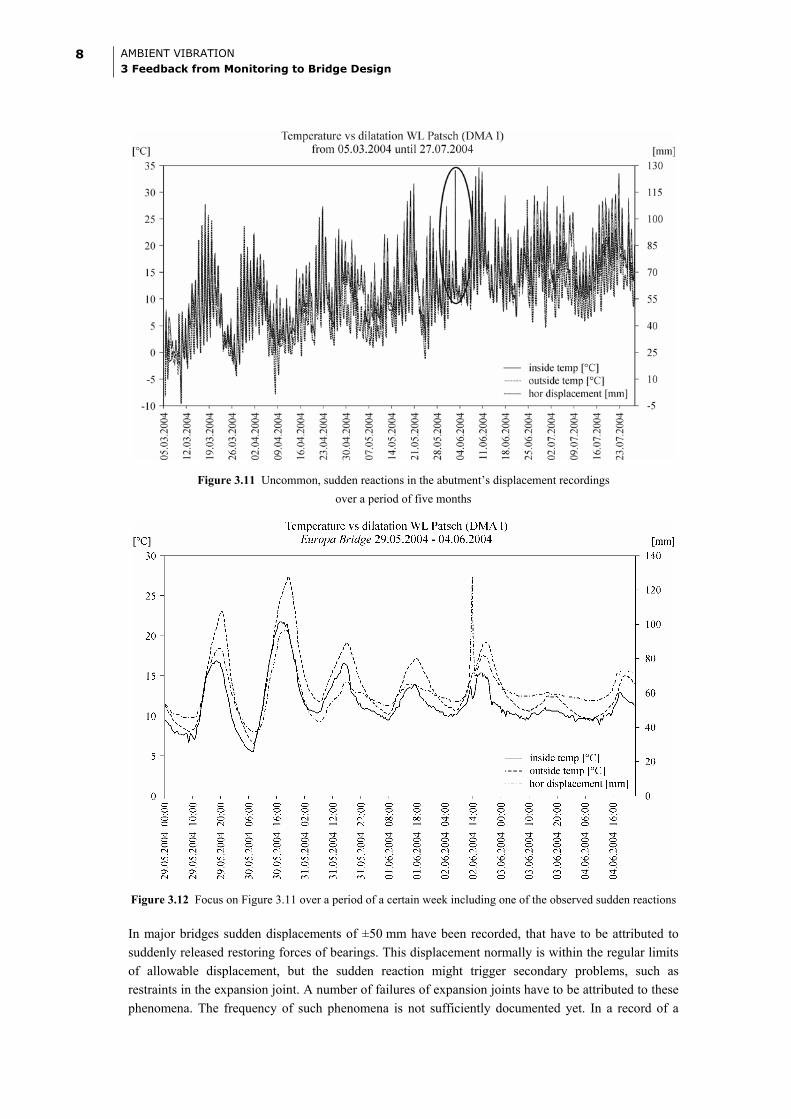
Figure 3.11 Uncommon, sudden reactions in the abutment’s displacement recordings over a period of five months
Figure 3.12 Focus on Figure 3.11 over a period of a certain week including one of the observed sudden reactions
In major bridges sudden displacements of ±50 mm have been recorded, that have to be attributed to suddenly released restoring forces of bearings. This displacement normally is within the regular limits of allowable displacement, but the sudden reaction might trigger secondary problems, such as restraints in the expansion joint. A number of failures of expansion joints have to be attributed to these phenomena. The frequency of such phenomena is not sufficiently documented yet. In a record of a

AMBIENT VIBRATION 3 Feedback from Monitoring to Bridge Design
9
major steel bridge of six month length, three such occasions have been detected (Figure 3.11, Figure 3.12).
Figure 3.13 Relative displacement due to sudden occasions of restraint recorded with a 3D-acceleration transducer at the top of a 200 m high pier subdivided
into the vertical (a), transverse (b) and longitudinal (c) direction
Figure 3.14 Displacement of the system’s neutral axis due to bearing reset forces of the flyover St. Marx (basis: acceleration sensors)

10 AMBIENT VIBRATION 3 Feedback from Monitoring to Bridge Design
Figure 3.15 System displacement due to bearing reset forces of the flyover St. Marx (basis: longitudinal laser-displacement sensors)
The consequences from these records are, that a realistic behaviour of a structure can be found through monitoring, which might explain damages in the outfitting. The displacements calculated for bearings and expansion joints might be not enough to cover extraordinary events as described. The centre of expansion of a structure can be dozens of meters away from the theoretical centre and influence the design of bearings and expansion joints (Figure 3.9).
3.2.5 Large Bridges vs. Small Bridges
In the beginning monitoring concentrated on large and important bridges. This has led to the impression that bridges normally perform very close to the theoretical behaviour determined and based on the design assumptions. The subsequent assessment of small bridges showed that it is considerably more difficult to achieve good results the smaller the structure is, because of different approaches taken towards these, considered not so important, structures. Another fact is that boundary conditions are much clearer in large structures.
The lesson learned from monitoring is that even higher attention should be paid to smaller bridges and that a number of provisions of construction codes fit very well for large structures, but underestimate small ones. Here in particular the subject of temperature, as explained in another chapter, has to be highlighted. Furthermore the correct modelling of the boundary conditions has to be taken care of.
3.2.6 Vibration Intensities
The subject of resonance in pedestrian bridges is well known and taken care of. Frequencies close to resonance, particular those of structural members, such as cantilever slabs, are not yet subject to consideration. Experience showed that the evaluation of the vibration intensities measured for a structure can give considerable information of fatigue and related problems. The assessment of vibration intensities therefore can give indicators on the expected lifetime of a structure and on local problems to be expected on structural elements in near future. It has been clearly demonstrated that bridges, where high vibration intensities have been recorded (Figure 3.16), most probably develop local problems in expansion joints, bearings, outfitting and particular in waterproofing.

AMBIENT VIBRATION 3 Feedback from Monitoring to Bridge Design
11
Figure 3.16 Intensity chart at the Europa Bridge of the Brenner Motorway (representing high vibration intensities)
Figure 3.17 Intensity chart at the S 36 Bridge of the A1 Motorway (representing low vibration intensities)
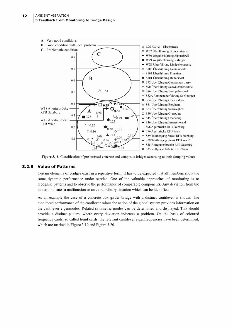
3.2.7 Damping Values of new Composite Bridges
Measurements taken at a number of new composite bridges show that the damping values determined at the newly built structure are considerably higher than the normal values of comparable concrete bridges or steel bridges. This might be attributed to the fact that the composite effect has to be established through a number of load cycles. After some time the damping values of these bridges have been stabilised in normal ranges. Deeper conclusions on these phenomena have not been drawn yet, but it might be expected that a sharp drop in damping indicates eventual problems with bonding or the triggering of a hidden local damage.
12 AMBIENT VIBRATION 3 Feedback from Monitoring to Bridge Design
Figure 3.18 Classification of pre-stressed concrete and composite bridges according to their damping values
3.2.8 Value of Patterns
Certain elements of bridges exist in a repetitive form. It has to be expected that all members show the same dynamic performance under service. One of the valuable approaches of monitoring is to recognise patterns and to observe the performance of comparable components. Any deviation from the pattern indicates a malfunction or an extraordinary situation which can be identified.
As an example the case of a concrete box girder bridge with a distinct cantilever is shown. The monitored performance of the cantilever minus the action of the global system provides information on the cantilever eigenmodes. Related symmetric modes can be determined and displayed. This should provide a distinct pattern, where every deviation indicates a problem. On the basis of coloured frequency cards, so called trend cards, the relevant cantilever eigenfrequencies have been determined, which are marked in Figure 3.19 and Figure 3.20.

AMBIENT VIBRATION 3 Feedback from Monitoring to Bridge Design
13
Figure 3.19 Course of frequencies at a certain concrete box-girder bridge - structure south
Figure 3.20 Course of frequencies at a certain concrete box-girder bridge - structure north
By comparison of the response spectra of both box girders and their cantilevers the share of cantilever vibration can be displayed directly.

14 AMBIENT VIBRATION 3 Feedback from Monitoring to Bridge Design
Figure 3.21 Spectrum of cantilever (continuous graph) and box girder (dashed graph)
Figure 3.22 Response spectrum of cantilever vibration
A detailed evaluation procedure analyzing the relation between the response spectrum and its energy content within the relevant frequency ranges leads to a certain behaviour pattern of the cantilevers along the bridge. Deviations from this pattern are typically indications of irregularity.
The enclosed figures show the pattern of an undamaged cantilever compared to a cantilever with minor corrosion damage of the transverse reinforcement.

AMBIENT VIBRATION 3 Feedback from Monitoring to Bridge Design
15
Figure 3.23 Acceptable behaviour pattern of the cantilevers along the bridge
Figure 3.24 Behaviour pattern of the cantilevers with indications of irregularity
This method is not good enough for detail localisation of the problem but it provides sufficient information on the quality of function of a structural element. By a very quick and cheap test it can be determined whether action is required or not.
3.2.9 Understanding of Behaviour
Complex bridge structures are often modelled in a rather simple way neglecting behaviour of the structure in the three-dimensional space. Monitoring is the recording of the actual behaviour of a structure. This comprises eventual drift or strain from temperature, as well as eventual construction mistakes, such as wrong placement of bearings or non release of restrainers. The enclosed example shows a case where a temporary fixation during construction has not been removed at the time of handover. The performance of the bridge has been considerably different than estimated. Monitoring has been able to detect this difference and asked for immediate correction (Figure 3.25).
Figure 3.25 Frequency Spectrum of Inn Bridge Hall West 1997 - 1998
Another important value is information on the actual displacement of a structure, particularly with regard to complicated cable supported structures, where such displacements could generate problems in traffic clearance or related interfaces.

16 AMBIENT VIBRATION 3 Feedback from Monitoring to Bridge Design
Another way of finding problems is to compare the expected behaviour with the measured one. In case of stay cables, protected by steel tubes against vandalism, the contact of the cable to the tube has been found through monitoring. The effective vibration length of the cable has been shortened by this contact. Such a problem can lead to drastic damage at a cable providing a sharp edge which introduces unintended bending. Monitoring is able to identify these problems.
Figure 3.26 Steyregg Bridge
3.2.10 Dynamic Factors
Current bridge design codes ask for dynamic factors mainly depending on the bridge span. The factor is considered to be 1.40 for components or directly effected members and varying between 1.00 and 1.40 depending on the span of a bridge. The lessons learned from monitoring are:
The dynamic factor provided by the code depending on the span length is actually conservative. All bridges so far showed smaller dynamic factors.
The dynamic factor for components sometimes exceeds the values considerably. The record factor measured has been 2.20.
The dynamic factor is also considerably depending on the speed of the vehicles. This can eventually be controlled by speed limits.
The consequences are that overloaded vehicles that drive on low speed will not produce harmful stresses. The low increase always has to be seen in conjunction with eventual speed effects. Consequently dynamically sensitive elements should be avoided in design.

AMBIENT VIBRATION 3 Feedback from Monitoring to Bridge Design
17
Figure 3.27 Dynamic factor of the flyover St. Marx
Another lesson learned is that the dynamic behaviour also depends on the type of structure designed. Bridges with box girders (Figure 3.27) are considerably less vulnerable to dynamic effects than bridges of other types of design (Figure 3.28).
Figure 3.28 Dynamic factor of the Boeschrüti Viaduct due to induced impact loading [3]
The dynamic vulnerability of a structure is depending on the acting mass. This is also clearly shown in monitoring records. Concrete bridges with a mass of 1.5 t/m2 or more are very little affected by dynamic amplification. Continuous girders react less violent to any impact. Elements with major differences in stiffness produce an inharmonic behaviour unfavourable for the structure.

18 AMBIENT VIBRATION 3 Feedback from Monitoring to Bridge Design
References
[1] Peeters, B.; De Roeck, G.: One year monitoring of the z 24-bridge: environmental influences versus
damage events. In Proceedings of IMAC 18, The International Modal Analysis Conference, pp. 1570-
1576, San Antonio, Texas, USA, February 2000
[2] De Roeck, G.;, Peeters, B.; Maeck, J.: Dynamic monitoring of civil engineering structures. Computational
Methods for Shell and Spatial Structures IASS-IACM 2000, Greece, 2000
[3] Cantieni, R.: Dynamic Load Tests on Highway Bridges in Switzerland – 60 Years Experience of EMPA.
Section Concrete Structures and Components, Report No. 211, Dübendorf, Switzerland 1983