Embed Size (px)
DESCRIPTION
arc welding
Citation preview

MANUFACTURING TECHNOLOGY – ISUB CODE: MEC230Unit 2Welding (Metal Joining) Processes& Metal Forming Processes
Unit 2 : Arc, Gas, Plastic Welding, LBW, EBW and Thermit Welding

Arc Welding (AW): Arc Welding is a process in which joining of the two metals pieces is achieved by the heat from an electric arc between an electrode and the work Electric energy from the arc produces temperatures in the range of 5000 to 6500 °C, hot enough to melt any metal Most Arc Welding processes add filler metal to increase volume and strength of weld joint What is an Electric Arc? An electric arc is a discharge of electric current across a gap in a circuit It is sustained by an ionized column of gas (plasma) through which the current flows To initiate the arc, electrode is brought into contact with work and then quickly separated from it by a short distance

Unit 2 : Arc WeldingEquipments:• A welding generator (D.C.) or Transformer (A.C.)• Two cables- one for work and one for electrode• Electrode holder• Electrode • Protective shield• Gloves • Wire brush• Chipping hammer• Goggles
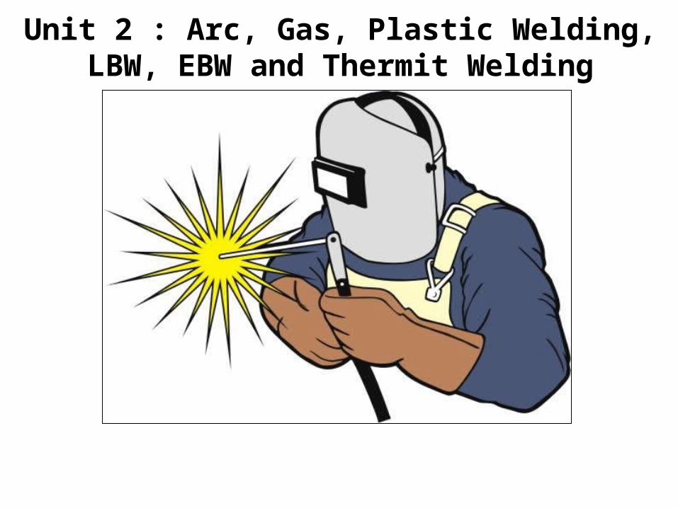
A pool of molten metal is formed near electrode tip, and as electrode is moved along joint, molten weld pool solidifiesArc Welding

Manual Metal Arc Welding

Arc Welding Advantages–Most efficient way to join metals– Lowest-cost joining method– Affords lighter weight through better utilization of materials– Joins all commercial metals– Provides design flexibility
Limitations• Manually applied, therefore high labor cost.• Need high energy causing danger• Not convenient for disassembly.• Defects are hard to detect at joints.
Arc Welding - Molten Metal and Flux Transfer to Weld Pool

Welding Condition Main Effects Current in excess of optimum Excess splash. Flat wide deposit. Deep penetration. Electrode overheats. Current less than optimum Slag difficult to control. Metal piles up. Poor shape. Poor penetration.Voltage in excess of optimum Deposit irregular and flat. Porosity. Splash. Voltage less than optimum Irregular support of weld metal. Arc destructions. Little penetration. Travel speed in excess of optimum Narrow thin weld bead. Undercut. Travel speed less than optimum Wide thick deposit. Difficulty in slag control. Optimum Welding conditions Smooth even weld deposit. Stable arc condition. Easily controlled slag. Little splash produced.
Welding Variables and Their Influence

Comparison of A.C. and D.C. arc weldingAlternating Current (from Transformer) AC machines less expensive to purchase and operate, but generally restricted to ferrous metals More efficiency Power consumption less Cost of equipment is less Higher voltage – hence not safe Not suitable for welding non ferrous metals Not preferred for welding thin sections Any terminal can be connected to the work or electrode

Comparison of A.C. and D.C. arc weldingDirect Current (from Generator) DC equipment can be used on all metals and is generally noted for better arc control Less efficiency Power consumption more Cost of equipment is more Low voltage – safer operation Suitable for both ferrous non ferrous metals preferred for welding thin sections Positive terminal connected to the work Negative terminal connected to the electrode

Two Basic Types of AW Electrodes•Consumable Electrodes– consumed during welding process – Source of filler metal in arc welding•Non-consumable Electrodes– not consumed during welding process– Filler metal must be added separatelyConsumable: Forms of consumable electrodes Welding rods are 9 to 18 inches length and 3/8 or ʺless in diameter and must be changed frequently Weld wire can be continuously fed from spools with long lengths of wire, avoiding frequent interruptions In both rod and wire forms, electrode is consumed by the arc and added to weld joint as filler metal

Non-consumable Electrodes • Made of tungsten which resists melting • Gradually depleted during welding (vaporization is principal mechanism) • Any filler metal must be supplied by a separate wire fed into weld poolConsumable Electrode AW Processes • Shielded Metal Arc Welding• Gas Metal Arc Welding• Flux‑Cored Arc Welding• Electrogas Welding• Submerged Arc Welding

Protection of the Molten Weld Pool• Contamination of the weld pool, by the atmosphere, can cause weld defects. • These defects can have an adverse effect on the joint efficiency, which may lead to failure. • Molten metal reacts with the atmosphere– Oxides and nitrides are formed– Discontinuities such as porosity– Poor weld metal properties
• All arc welding processes employ some means of shielding the molten weld pool from the air• Therefore, the weld pool should be protected from the atmosphere until it has completely solidified.• A variety of fluxes and shielding gases are employed by the arc welding process to provide atmospheric shielding.

Arc Shielding• At high temperatures in AW, metals are chemically reactive to oxygen, nitrogen, and hydrogen in air – Mechanical properties of joint can be degraded by these reactions – To protect operation, arc must be shielded from surrounding air in AW processes
• Arc shielding is accomplished by: – Flux– Shielding gases, e.g., argon, helium, CO2

Welding Flux• Welding fluxes have three forms. i. Granular form: Flux can be poured over the weld pool in a granular form as in submerged arc welding, ii. Electrode wire coating form: It can be coated on the exterior of the electrode as in shielded arc welding, or iii. Electrode core form: It can be placed in the interior core of the electrode as in flux-cored arc welding.• Fluxes melt to form a protective slag over the weld pool• Other purposes– Contain scavenger elements to purify weld metal– Contain metal powder added to increase deposition rate– Add alloy elements to weld metal– Decompose to form a shielding gas

Shielding Gas Shielding gas forms a protective atmosphere over the molten weld pool to prevent contamination Shielding gas can be a single pure gas or a mixture of two or more gases. Inert shielding gases, argon or helium, keep out oxygen, nitrogen, and other gases Active gases, such as oxygen and carbon dioxide, are sometimes added to improve variables such as arc stability and splash reduction Argon is often used in the flat and horizontal position, since it is heavier than air. Helium can be used in the overhead position, since it is lighter than air. Helium has a characteristic of producing a “hotter” arc than argon.

Shielded Metal Arc Welding (SMAW) Uses a consumable electrode consisting of a filler metal rod coated with chemicals that provide flux and shielding Sometimes called "stick welding“ Shielded metal arc welding (stick welding) performed by a human welder

Shielded Metal Arc Welding (SMAW) Composition of filler metal usually close to base metal Coating: powdered cellulose mixed with oxides and carbonates, and held together by a silicate binder Welding stick is clamped in electrode holder connected to power source

Advantages of Shielded Metal Arc Welding (SMAW)Shielded Metal Arc Welding (SMAW) is by far the most widely used arc welding process. It is very popular because of it’s many advantages. The equipment is relatively easy to use, inexpensive, and portable or Flexible The filler metal and means for protecting the weld pool are provided by the covered electrode. It is a versatile process in that it can be used on carbon steels, low alloy steels, stainless steels, cast irons, copper, nickel, and aluminium. Used in Underwater welding

Shielded Metal Arc Welding (SMAW) Underwater welding

Disadvantages of Shielded Metal Arc Welding (SMAW)Aspects of the SMAW process present disadvantages from a quality standpoint; These include a dependence on operator technique, as well as the starting and stopping of the arc to change electrodes. Slag entrapment and lack of fusion to the base-metal or previous passes can occur during welding as a result of improper torch manipulation by the welder. Improper cleaning can also cause slag inclusion defects. In addition, at each start and stop there is a possibility of porosity being formed since it takes some time for the slag to melt and form a protective gas over the molten weld pool. The heat of the welding arc is too high for some lower melting metals. High current levels may melt coating prematurely

Disadvantages of Shielded Metal Arc Welding (SMAW) SMAW has a low weld metal deposition rate compared to other processes. This is because each welding rod contains a finite amount of metal (Sticks must be periodically changed) As each electrode is used, welding must be stopped and a new rod inserted into the holder. A 12-inch electrode may be able to deposit a bead 6-8 inches long.The overall productivity of the process is delayed by: Frequent changing of electrodes, Inter-pass cleaning (grinding, brushing, etc.), Grinding of arc initiation points and stopping points, Slag inclusions which require removal of the defect and rewelding of the defective area.

SMAW Electrode ClassificationE7018
This slide illustrates the American Welding Society Electrode Classification System found in Code A5.5-96. The E7018 electrode is probably one of the most commonly used. The E indicates that this is an electrode, The 70 indicates that the weld metal deposited has at least 70,000 pounds per square inch tensile strength, The 1 indicates that the electrode can be used in all positions, and The 8 indicates that it is a low hydrogen electrode.

SMAW Electrode Classification ExampleE7018-A1-H8R
Additional information May be given by a series of suffixes separated by dashes. In this above example, The “A1” indicates Chemical composition for undiluted weld metal. The “H8” indicates conformity to the diffusible hydrogen test. (8 ml of H2 per 100g of deposited metal). Finally, the “R” indicates conformity to an absorbed moisture test (less than 0.4% Moisture Content).

SMAW Electrode Classification Common electrode specification can become confusing to the user and manufacturer, depending upon the number of special requirements desired for an application. Some common American Welding Society SMAW specifications for electrode classifications are presented in AWS Website They can be obtained from AWS at the website listed.• ANSI/AWS - 5.1 : Specification for Covered Carbon Steel• ANSI/AWS - 5.5 : Specification for Low Alloy Steel• ANSI/AWS - 5.4 : Specification for Corrosion Resistant Steel AWS Website:
http://www.aws.org

Gas Metal Arc Welding (GMAW) GMAW-referred by subnames as Metal Inert Gas (MIG) welding or Metal Active Gas (MAG) welding, is a semi-automatic or automatic arc welding process Uses a consumable bare metal wire as electrode with shielding by flooding arc with a gas Shielding gases include argon and helium for aluminium welding, and CO2 for steel welding Bare electrode wire plus shielding gases eliminate slag on weld bead, & No need for manual grinding and cleaning of slag
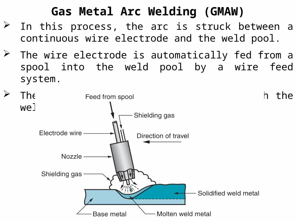
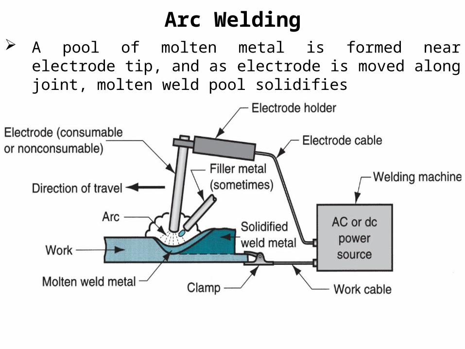
Gas Metal Arc Welding (GMAW) In this process, the arc is struck between a continuous wire electrode and the weld pool. The wire electrode is automatically fed from a spool into the weld pool by a wire feed system. The wire feed draws the electrode through the welding torch.

Better arc time because of continuous wire electrode (Sticks must be periodically changed in SMAW) Better use of electrode filler metal than SMAW (End of stick cannot be used in SMAW) Higher deposition rates Eliminates problem of slag removal No time is lost in order to change electrodes (as in SMAW) or to remove slag (as in SMAW, FCAW, and SAW) GMAW is easily mechanized or automated and is very often used in conjunction with robots.
GMAW Advantages over SMAW

GMAW equipment is more complex and expensive than SMAW equipment. The equipment consists of a power supply, wire feeder and a welding gun. Each of these items require more skill and knowledge to operate and maintain as compared to SMAW. The GMAW torch (or gun) is bulky compared to the SMAW electrode. This restricts the conventional use of the process to applications where there is adequate access to the weld joint by the torch. Methods have been developed for narrow gap welding using the GMAW process, however, these methods require extensive equipment and procedure development to implement.
GMAW Limitations

Gas Metal Arc Welding (GMAW) The shielding gas used for shielding, affects the type of metal transfer, the penetration depth, and the bead shape. The ionization potential of the gas is the ability of the gas to give up electrons and is the characteristic which determines the characteristics of the arc. The ionization potential (IP) of the gas can have an effect on welding characteristics such as Arc heat, stability, & starting.

Gas Metal Arc Welding (GMAW)

GMAW Filler Metal Designations
The classification of solid wires is shown above. The most important aspects from the classification are: The electrode is a solid wire as designated by the ER and the S, The UTS of the weld metal (70,000 psi in the above example)

GMAW Filler Metal Designations
The chemical composition of the weld wire and the shielding gas used to achieve the stated ultimate tensile strength requirements as designated by the number 6. The chemical composition of the welding wire effects the usability on different surface finishes. For example, the S-6 designation shown above is used for welding over rust and oily plates since it contains a higher amount of the deoxidizer silicon.

Flux‑Cored Arc Welding (FCAW) Flux Cored Arc Welding (FCAW) uses a tubular wire that is filled with a flux. Electrode is a continuous consumable tubing (in coils) containing flux and other ingredients (e.g., alloying elements) in its core The arc is initiated between the continuous wire electrode and the workpiece. The flux, which is contained within the core of the tubular electrode, melts during welding and shields the weld pool from the atmosphere. Direct current, electrode positive (DCEP) is commonly employed as in the FCAW process.

Flux‑Cored Arc Welding (FCAW) Presence or absence of externally supplied shielding gas distinguishes: (1) self‑shielded - core provides ingredients for shielding, (2) gas‑shielded - uses external shielding gases

Flux‑Cored Arc Welding (FCAW) There are two basic process variants;
Self shielded FCAW (without shielding gas) and Gas shielded FCAW (with shielding gas).
The difference in the two is due to different fluxing agents in the consumables, which provide different benefits to the user. Usually, self-shielded FCAW is used in outdoor conditions where wind would blow away a shielding gas. The flux in gas-shielded FCAW provides for deoxidation of the weld pool and, to a smaller degree than in self-shielded FCAW, provides secondary shielding from the atmosphere. The flux is designed to support the weld pool for out-of position welds. This variation of the process is used for increasing productivity of out-of-position welds and for deeper penetration.

Flux‑Cored Arc Welding (FCAW)

Advantages of Flux‑Cored Arc Welding (FCAW) The FCAW process combines the best characteristics of SMAW and GMAW. It uses a flux to shield the weld pool, although a supplemental shielding gas can be used. A continuous wire electrode provides high deposition rates. The flux for FCAW consumables can be designed to support larger weld pools out of position and provide higher penetration compared to using a solid wire (GMAW). Larger welds can be made in a single pass with larger diameter electrodes where GMAW and SMAW would need multiple passes for equivalent weld sizes. This improves productivity and reduces distortion of a weldment.

Disadvantages of Flux‑Cored Arc Welding (FCAW) As with SMAW, the slag must be removed between passes on multi-pass welds. This can slow down the productivity of the application and result in possible slag inclusion discontinuities. For gas shielded FCAW, porosity can occur as a result of insufficient gas coverage. Large amounts of fume are produced by the FCAW process due to the high currents, voltages, and the flux inherent with the process. Increased costs could be incurred through the need for ventilation equipment for proper health and safety. FCAW is more complex and more expensive than SMAW because it requires a wire feeder and welding gun. The complexity of the equipment also makes the process less portable than SMAW.

Flux‑Cored Arc Welding (FCAW)

FCAW Electrode Classification
Classification for FCAW wire is designed to tell the user the ultimate tensile strength of the as welded weld metal, the position(s) it can be used in, and its usability characteristics.

FCAW Electrode Classification
In the example above, The ultimate tensile strength of the weld metal is specified as 70 ksi. Positions the electrode can be used in are specified by the third item in the specification, 0- for flat and 1 for all positions. The “T” designates that this is a flux cored wire. The usability and performance of the consumable is specified after the dash. In the example above the 1 stands for a general purpose electrode using DCEP and for multi-pass welding.

Electrogas Welding (EGW) Uses a continuous consumable electrode, flux‑cored wire or bare wire with externally supplied shielding gases, and molding shoes to contain molten metal
When flux‑cored electrode wire is used and no external gases are supplied, then special case of self‑shielded FCAW When a bare electrode wire used with shielding gases from external source, then special case of GMAW
Electrogas welding using flux‑cored electrode wire: (a) front view with molding shoe removed for clarity, and (b) side view showing molding shoes on both sides

Submerged Arc Welding (SAW) Submerged arc welding (SAW) employs a granular flux which is fed into the joint around the tip of the welding torch by a hose from a flux hopper. The arc is struck between the wire and the workpiece beneath the flux cover. Both the arc and the molten weld pool are shielded by the resulting envelope of molten flux and a layer of unfused granular flux particles. A vacuum follows behind the torch to collect the unfused flux for future use.

Submerged Arc Welding (SAW)
The filler metal is a continuously-fed wire electrode like GMAW and FCAW. However, higher deposition rates can be achieved using SAW by using larger diameter electrodes and higher currents. Since the process is almost fully mechanized, several variants of the process can be utilized such as multiple torches and narrow gap welding.

Submerged Arc Welding (SAW)
Schematic illustration of the submerged-arc welding process and equipment.

Advantages of Submerged Arc Welding (SAW) SAW has the highest deposition rate of all the arc welding processes making it ideal for thick section and multi-pass welding. Variations of the process can utilize multiple torch, and narrow groove welding to increase productivity. Since the arc is completely submerged in the flux, there is no arc radiation. Screens or light filtering lenses are not needed. The smoke and fumes are trapped within the flux and thus minimizing smoke and fumes . Since the process is simple to mechanize and easily automated, it is extremely consistent once a procedure is qualified. SAW can be used on a wide variety of materials.

Disadvantages of Submerged Arc Welding (SAW)There are some limitations with the process, The flux which shields the arc and weld pool obstructs the operator’s view of the joint and molten weld pool. Observation of the pool and joint impossible during welding; thus, correction of problems during welding can be very difficult. Flux is subject to contamination ⇒ porosity Normally not suitable for thin material Restricted to the flat position for grooves - flat and horizontal for fillets Slag removal required Flux handling equipment

Applications of Submerged Arc Welding (SAW)
Steel fabrication of structural shapes (e.g., I‑beams) Seams for large diameter pipes, tanks, and pressure vessels Welded components for heavy machinery Most steels (except hi C steel) Not good for nonferrous metals

Submerged Arc Welding (SAW)

Selection of Welding Rods Filler rod should have a tensile strength greater than the metal to be joined. Rod must also be compatible with the welded metal Welding positions required Welding current (ac or dc) Joint design (groove, butt, fillet, etc.) Thickness and shape of the base metal Service conditions and specifications Production efficiency and job conditions
Nonconsumable Electrode Processes Gas Tungsten Arc Welding Plasma Arc Welding Carbon Arc Welding Stud Welding

Gas Tungsten Arc Welding (GTAW) Uses a non-consumable tungsten electrode and an inert gas for arc shielding Melting point of tungsten = 3410 °C Also known as “Tungsten Inert Gas (TIG) welding” In Europe, called "WIG welding" Used with or without a filler metal When filler metal used, it is added to weld pool from separate rod or wire Applications: aluminium and stainless steel mostly

Gas Tungsten Arc Welding (GTAW)

Advantages and Disadvantages of GTAW
Advantages:• High quality welds for suitable applications• No splash because no filler metal through arc• Little or no post-weld cleaning because no fluxDisadvantages:• Generally slower and more costly than consumable electrode AW processes

Plasma Arc Welding (PAW) Special form of GTAW in which a restricted plasma arc is directed at weld area Tungsten electrode is contained in a nozzle that focuses a high velocity stream of inert gas (argon) into arc region to form a high velocity, intensely hot plasma arc stream Temperatures in PAW reach 28,000°C, due to constriction of arc, producing a plasma jet of small diameter and very high energy density

Plasma Arc Welding (PAW)
Two types of plasma-arc welding processes: (a) transferred, (b) non-transferred. Deep and narrow welds can be made by this process at high welding speeds.
Water Cooled Nozzle

Advantages and Disadvantages of PAW Hydrogen plasma burns even hotter than hydrogen gas, permitting the welding of extremely high-melting-point metals. Very clean procedure that results in very little slag or foreign matter in the weld. Advantages: Good arc stability and excellent weld quality Better penetration control than other AW processes High travel speeds Can be used to weld almost any metalsDisadvantages: High equipment cost Larger torch size than other AW processes Tends to restrict access in some joints

Plastic Welding or Pressure WeldingResistance Welding (RW) A group of welding processes that use a combination of heat and pressure to accomplish joining Heat generated by electrical resistance to current flow at junction to be welded Principal RW process is resistance spot welding (RSW)

The heat generated during resistance welding is given by following expression:
H = I2 R T
Where, H is heat generated
I is current in amperes
R is resistance of area being welded
T is time for the flow of current.
Plastic Welding or Pressure WeldingResistance Welding (RW)

Resistance Welding (RW)Principle of Resistance spot Welding
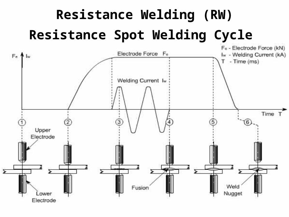
Resistance Welding (RW)Resistance Spot Welding Cycle

Resistance Spot Welding (RSW) Resistance welding process in which heating of surfaces of a lap joint is achieved at one location by opposing electrodes Used to join sheet metal parts Widely used in mass production of automobiles, metal furniture, appliances, and other sheet metal products Typical car body has ~ 10,000 spot welds Annual production of automobiles in the world is measured in tens of millions of units

Components in Resistance Spot Welding Parts to be welded (usually sheet metal) Two opposing electrodes Means of applying pressure to squeeze parts between electrodes Power supply from which a controlled current can be applied for a specified time duration

Resistance Spot Welding (RSW) (a) Spot welding cycle and (b) Plot of force and current Cycle: (1) parts inserted between electrodes, (2) electrodes close, (3) current on, (4) current off, (5) electrodes opened

Advantages and Drawbacks of Resistance WeldingAdvantages: No filler metal required High production rates possible Lends itself to mechanization and automation Lower operator skill level than for arc welding Good repeatability and reliability Disadvantages: High initial equipment cost Limited to lap joints for most RW processes

Resistance Seam Welding (RSEW)Uses rotating wheel electrodes to produce a series of overlapping spot welds along lap joint, Can produce air‑tight joints
Applications: Gasoline tanks Automobile mufflers Various sheet metal containers

Oxyfuel Gas Welding (OFW) Group of fusion welding operations that burn various fuels mixed with oxygen Oxyfuel gas is also used in flame cutting torches to cut and separate metal plates and other parts Most important OFW process is Oxyacetylene Welding (OAW) The oxyacetylene welding process uses a combination of oxygen and acetylene gas to provide a high temperature flame. OAW is a manual process in which the welder must personally control the torch movement and filler rod application Cylinders contain oxygen and acetylene gas at extremely high pressure.

Gas Welding Equipment1. Gas Cylinders : Pressure Oxygen – 125 kg/cm2 Acetylene – 16 kg/cm2 2. Regulators Working pressure of oxygen 1 kg/cm2 Working pressure of acetylene 0.15 kg/cm2 Working pressure varies and depends upon the thickness of the work pieces welded.3. Pressure Gauges4. Hosepipes5. Welding torch 6. Check valve7. Non return valve

Oxyacetylene Welding (OAW)

Oxyacetylene Welding (OAW) Fusion welding performed by combustion of acetylene and oxygen Flame is directed by a welding torch Filler metal is sometimes added & its composition must be similar to base metal Filler rod often coated with flux to clean surfaces and prevent oxidation

Torch Used in Oxyacetylene Welding(b) Cross-section of a torch used in oxyacetylene welding. The acetylene valve is opened first; the gas is lit with a spark lighter; then the oxygen valve is opened and the flame adjusted.(c) Basic equipment used in oxyfuel-gas welding. To ensure correct connections, all threads on acetylene fittings are left-handed, whereas those for oxygen are right-handed. Oxygen regulators are usually painted green, acetylene regulators red.
(a) General view

Acetylene (C2H2) Most popular fuel among OFW group It is capable of higher temperatures up to 3480°C Two stage reaction of acetylene and oxygen:First stage reaction (inner cone of flame) C2H2 + O2 → 2CO + H2 + heatSecond stage reaction (outer envelope)2CO + H2 + 1.5O2 → 2CO2 + H2O + heat

Oxyacetylene Torch Maximum temperature reached at tip of inner cone, Outer envelope spreads out and shields work surface from atmosphere Shown below is neutral flame of oxyacetylene torch indicating temperatures achieved

Oxyacetylene Flames Used in Welding
Three basic types of oxyacetylene flames used in oxyfuel-gas welding and cutting operations: (a) neutral flame; (b) oxidizing flame; (c) carburizing, or reducing, flame. The gas mixture in (a) is basically equal volumes of oxygen and acetylene

Oxyfuel Gas Welding (OFW)Advantages of an oxy-acetylene weld Inexpensive Requires very little specialized equipment. Disadvantages Any traces of carbon left in the weld will weaken it.

Safety Issue in OAW Together, acetylene and oxygen are highly flammable C2H2 is colorless and odorless It is therefore processed to have characteristic garlic odor C2H2 is physically unstable at pressures much above 1 atm Storage cylinders are packed with porous filler material saturated with acetone (CH3COCH3) Acetone dissolves about 25 times its own volume of acetylene Different screw threads are standard on C2H2 and O2 cylinders and hoses to avoid accidental connection of wrong gases

Gas Cutting
Automatic Gas Cutting Manual Gas Cutting

Alternative Gases for OFW Methylacetylene‑Propadiene (MAPP) Hydrogen Propylene Propane Natural Gas

Other Welding Processes Fusion Welding processes that cannot be classified as arc, resistance, or oxyfuel welding Use unique technologies to develop heat for melting Applications are typically unique Processes include:
Electron beam welding Laser beam welding Electroslag welding Thermit welding

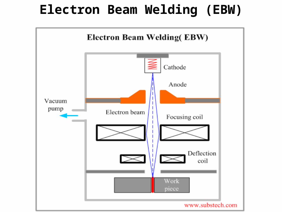
Electron Beam Welding (EBW) Fusion welding process in which heat for welding is provided by a highly‑focused, high‑intensity stream of electrons striking work surface Electron beam gun operates at: High voltage (e.g., 10 to 150 kV typical) to accelerate electrons Beam currents are low (measured in milliamps) The electron gun melts the parent metal, and the molten metal flows to fill the gap Heat affected zone is very narrow Welds can be several inches deep, and leaves a very clean weld. Welding must be done in a vacuum.
Electron Beam Welding (EBW)

Electron Beam Welding Vacuum Chamber EBW had to be carried out in a vacuum chamber to minimize disruption of electron beam by air molecules Three Vacuum Levels in EBW1. High-vacuum welding – welding in same vacuum chamber as beam generation to produce highest quality weld2. Medium-vacuum welding – welding in separate chamber but partial vacuum3. Non-vacuum welding – welding done at or near atmospheric pressure, with work positioned close to electron beam generator

EBW Advantages and DisadvantagesAdvantages: High‑quality welds, deep and narrow profiles Limited heat affected zone, low thermal distortion No flux or shielding gases neededDisadvantages: High equipment cost Precise joint preparation & alignment required Vacuum chamber required Safety concern: EBW generates x‑rays

Laser Beam Welding (LBW) Fusion welding process in which combination is achieved by energy of a highly concentrated, coherent light beam focused on joint LBW normally performed with shielding gases to prevent oxidation Filler metal not usually added LBW often used for small parts The heat from laser can be used to heat the surface of material or penetrate the entire depth of the joint (good for thin gauge metals). The major problems with the current lasers is the cost and bulk of the power source.

Laser Beam Welding (LBW) A laser beam that becomes highly focused is an excellent source of concentrated energy. This energy is used for many welding applications and also cutting and heat treating. Two basic types of lasers are used in welding:
Solid-state And Gas Lasers.
Solid-state lasers are made of a single elongated crystal rod. Nd:YAG is the most common solid-state laser used for welding. The most common gas laser is the carbon dioxide laser. It is used most widely for welding.

Laser Beam Welding (LBW)• Single pass weld penetration up to 3/4” in steel• Materials need not be conductive• No filler metal required• Low heat input produces low distortion• Does not require a vacuum

CO2 lasers: higher power, better beam quality in terms of focusability, higher speeds and deeper penetration for materials that don’t reflect its light, lower start-up and operation costs.Nd:YAG lasers: easy beam alignment, easier maintenance, smaller equipment, more expensive safety measures
Laser Beam Welding (LBW)

Laser Beam Welding (LBW)

Laser Beam Welding (LBW)Advantages: Deep and narrow welds can be done. Minimal heat affected zones in welds created. Excellent metallurgical quality will be established in welds. Ability to weld smaller, thinner components. Increased travel speeds. Non-contact welding.

Laser Beam Welding (LBW)Disadvantages: High initial start-up costs Part fit-up and joint tracking are critical Not portable Metals such as copper and aluminium have high reflectivity and are difficult to laser weld High cooling rates may lead to materials problems

Laser Beam Welding (LBW)Applications Laser Beam Welding (LBW): Aerospace. Defense/military. Electronics. Research & development. Medical. Sensors & instrumentation. Petrochemical refining. Communications & energy.

Comparison: LBW vs EBW No vacuum chamber required for LBW No x‑rays emitted in LBW Laser beams can be focused and directed by optical lenses and mirrors LBW not capable of the deep welds and high depth‑to‑width ratios of EBW Maximum LBW depth = ~ 19 mm (3/4 in), Whereas EBW depths = 50 mm (2 in)

Thermit Welding (TW) FW process in which heat for joining is produced by superheated molten metal from the chemical reaction of thermite Thermite = mixture of Al and Fe3O4 fine powders that produce an exothermic reaction when ignited Filler metal obtained from liquid metal Process used for joining, but has more in common with casting than welding

Thermit Welding (TW)(1) Thermit ignited; (2) crucible tapped, superheated metal flows into mold; (3) metal solidifies to produce weld joint
TW Applications Joining of railroad rails Repair of cracks in large steel castings and forgings Weld surface is often smooth enough that no finishing is required