Embed Size (px)
Citation preview
30047IN-5/23/14 REV. K PCN2165 ©2011 CEQUENT PERFORMANCE PRODUCTS, INC PRINTED IN CHINA
You can take it with you. Plymouth MI
INSTRUCTION MANUAL
16K - Fifth Wheel Hitch Product No.
30047
For Installation Assistance or Technical Help, Call 1-888-521-0510
WARNING HANG TAG
HITCH HANDLE
HANDLE LATCH
WARNING DECAL
WARNING DECAL
JAWS TO HOLD
KING PIN
SKID PLATE
RAMP
FUNNEL FOR
TRAILER KING PIN
(1) Provide this Manual to end user.
(2) Physically demonstrate hitching and unhitching
procedures in this Manual to end user.
(3) Have end user demonstrate that he/she
understands procedures.
DEALER/INSTALLER: END USER:
(1) Read and follow this Manual every time you use hitch.
(2) Save this Manual and Hitch Warning Hang Tag for future reference.
(3) Pass on copies of Manual and Hitch Warning Hang Tag to any other
user or owner of hitch.
(4) Never remove hitch warning decals as shown on the cover of this
manual. If damaged, contact Reese (1-888-521-0510 or
www.reeseprod.com) for free replacement.

30047IN-5/23/14 REV. K PCN2165 ©2011 CEQUENT PERFORMANCE PRODUCTS, INC PRINTED IN CHINA
2
1. GUIDELINES FOR MATCHING TOW VEHICLE AND TRAILER P. 2
2. ASSEMBLY INSTRUCTIONS P. 4
3. BEFORE EACH TRIP P. 5
4. HITCHING PROCEDURE P. 5
5. PULL TEST P. 9
6. UNHITCHING PROCEDURE P. 9
7. MAINTENANCE P. 10
8. REESE FIVE YEAR LIMITED WARRANTY P. 10
1. Reese hitches are designed for use with recreational fifth wheel trailers only. Hitch applications other than recreational fifth
wheel trailers must be approved in writing by Reese’s Engineering Department.
2. Use only a SAE 2-inch kingpin with your Reese Fifth Wheel Hitch.
3. Approximately 15%-25% of trailer weight should be on hitch (Pin Weight). See Fig. 2.
FACTORY TRAILER + FULL WATER TANKS + CARGO, ETC.
= GROSS TRAILER WEIGHT Fig. 1
15-25%
GROSS TRAILER
WEIGHT
(PIN WEIGHT)
75-85%
GROSS TRAILER
WEIGHT
Fig. 2
GROSS TRAILER WEIGHT
GUIDELINES FOR MATCHING HITCH TRUCK AND TRAILER
WARNING:
Failure to follow these instructions may result in death or serious injury!
INDEX
WARNING: Trailer and its contents together must not exceed truck, hitch and/or trailer tow
ratings.
Towing vehicle must have a manufacturer’s rated towing capacity equal to or
greater than the gross trailer weight (dry weight of the trailer plus payload of the
trailer). (See Fig. 1)
Gross weight of trailer must not exceed 16,000 pounds.
King pin weight must not exceed 4,000 pounds (See Fig. 2). If in doubt have king
pin weight measured by qualified facility.
30047IN-5/23/14 REV. K PCN2165 ©2011 CEQUENT PERFORMANCE PRODUCTS, INC PRINTED IN CHINA
3
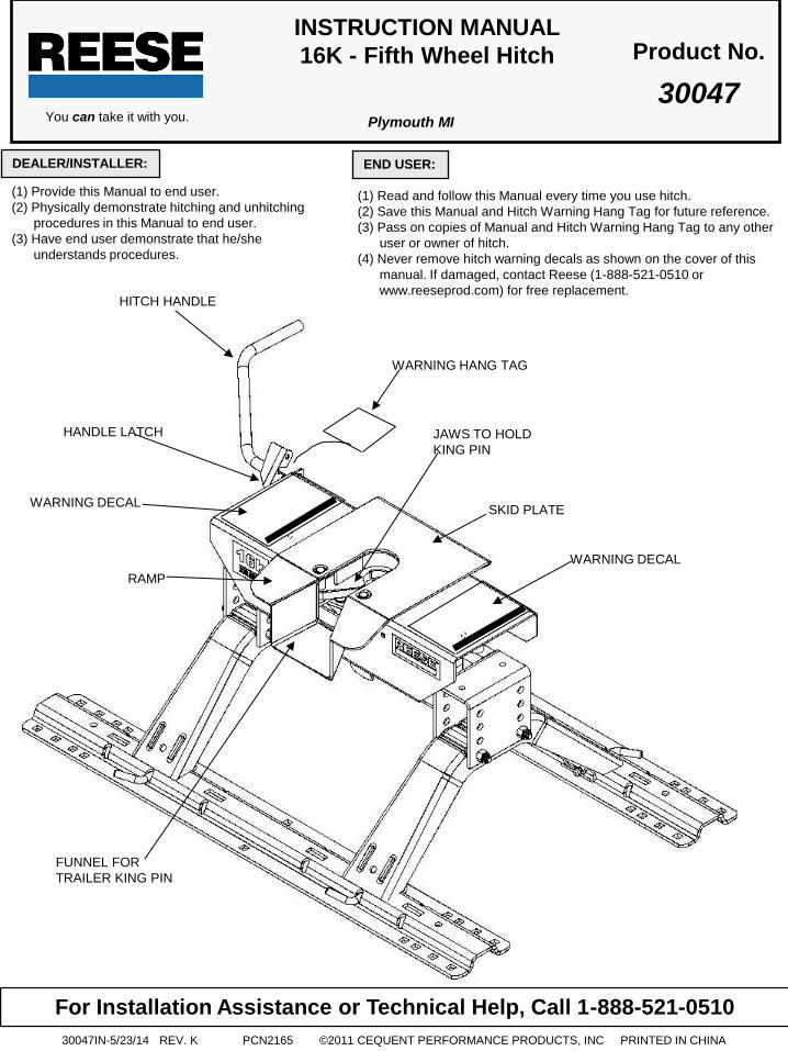
4. Trucks come in many different configurations. Reese hitches are designed for use in light trucks such as the Ford F-
Series, the Chevy Silverado and the Dodge Ram. Reese recommends the use of long bed (8ft) light trucks for the best
combination in truck - trailer turning clearance.
5. If a short bed pickup (less than 8 ft. but longer than 6 ft.) is to be used for towing, Reese recommends the trailer be
equipped with an extended pin box to help gain additional truck - trailer turning clearance (See trailer manufacturer for
options) (See Fig. 4). It also may be helpful to add a Reese Kwik-Slide (Part # 30048) for increased turning clearance for
low speed, non-highway maneuvering.
6. The height of the hitch and the pin box should be adjusted so the trailer is approximately level as it is towed. Allow
approximately 6 inches clearance between the top of the pickup walls and the underside of the front of the trailer for pitch
and roll of the trailer. (See Fig. 5). Allow more clearance between pickup walls and trailer for off road use.
KING PIN
RV TRAILER
TRUCK
Fig. 3
Conventional Pin Box Extended Pin Box
Fig. 4
Rule of thumb: The distance from the back of the truck cab to the center of the rear truck
axle (“X” in Fig. 3), should be approximately 4 inches greater than one-half
the trailer width (“Y” in Fig.3)
WARNING: Do Not install this fifth wheel hitch on or attempt to tow with a short bed pickup
truck that has a bed shorter than 6 ft.!
.
Approximately 6 Inches
Level Trailer
Fig. 5

30047IN-5/23/14 REV. K PCN2165 ©2011 CEQUENT PERFORMANCE PRODUCTS, INC PRINTED IN CHINA
4
1. Reference Fig. 20 on back page. Numbers in parentheses refer to parts in Fig. 20.
2. 5th Wheel Kit is contained in two cartons. Unpack and become familiar with parts on parts list. Base rails, brackets and
hardware are in separate kit (part no. 30035) with separate Installation Instructions for Fifth Wheel Rail Mounting Kit.
3. Place two base rails (25) across bed of truck (See Fig. 7). Select one leg (28) and place tabs through the middle
rectangular slot in the base rails. Slip long pull pins (11) through holes in base rails from the inside out as shown so the cotter
pins are on the outside of the base rails. Repeat for other leg. Secure pull pins with spring retaining pins (12).
4. Select head support (27) and install on leg aligning holes for hitch height desired. (Lowest position 13" highest 17").
Install four 1/2-13 x 4.5" Hex bolts (32), (with heads toward inside as shown) and lock nuts (33).
5. Torque 1/2" nuts to 75 lb. ft.
6. Install base rails and mounting brackets as described in "Installation Instructions for 5th Wheel Rail Mounting Kit,” Part #
30035.
ASSEMBLY INSTRUCTIONS
WARNING:
Connection for trailer wiring should be in the side of the truck bed between the driver’s
seat and the wheel well for the back truck axle
Installation of connection rearward of the wheel well may result in user placing body
between truck and trailer. WHENEVER POSSIBLE, AVOID PUTTING BODY UNDER TRAILER
OR BETWEEN TRUCK AND TRAILER!
If you need to place any part of your body under trailer or between truck and trailer:
All trailer tires MUST be blocked in front and behind each tire AND
Trailer landing gear MUST be resting on firm ground AND
Truck MUST be stationary, in park, with emergency brake on!
WARNING: Do Not use this hitch for towing a trailer with a pin box that could come into contact with
or interfere with the latch for the hitch handle when turning! (See Fig. 6) If the pin box
contacts the hitch handle or its latch when turning, the trailer may become unhitched.
WARNING Base rails must be bolted through the floor of the pickup to the brackets that attach to
the truck frame. DO NOT INSTALL BY FASTENING TO THE FLOOR OF THE PICKUP BOX
ONLY. The floor alone is not strong enough to carry the loads imposed by the trailer.
KING PIN
BOTTOM OF PIN BOX LATCH
Fig. 6
Fig. 7
BASERAILS

30047IN-5/23/14 REV. K PCN2165 ©2011 CEQUENT PERFORMANCE PRODUCTS, INC PRINTED IN CHINA
5
1. Lubricate skid plate surface of the hitch (see figure on cover of Manual) with automotive type chassis grease or use a
plastic lube plate to provide a lubricated surface. Use engine oil to lubricate pivot points of moving parts within the hitch.
2. Plastic lube plates (Reese No. 74295) can be used to avoid messy grease. The plastic lube plate must not exceed 3/16 of
an inch in thickness to ensure hitch will operate properly. Lube plates must be 10 inches in diameter or larger to properly
distribute king pin weight.
3. Before each trip or maneuver, operate the handle and check that the jaws open and close freely.
4. See that all hitch pull pins (# 11 on Fig. 19) are in place and the spring retaining pins (#12 on Fig. 19) are installed.
IMPORTANT: YOU ARE RESPONSIBLE FOR SAFE HITCHING AND UNHITCHING OPERATIONS. DO NOT RELY ON
OTHERS TO PERFORM YOUR DUTIES. YOU MUST PERSONALLY MAKE SURE THE FOLLOWING
STEPS ARE PERFORMED IN THE FOLLOWING ORDER!
WARNING:
FAILURE TO FOLLOW THESE INSTRUCTIONS MAY RESULT IN DEATH OR SERIOUS INJURY.
1. Place blocks (sometimes called “chocks”) firmly against front and rear of each trailer wheel to prevent any possible
forward or rearward motion. DO NOT REMOVE BLOCKS UNTIL EACH OF THE FOLLOWING STEPS AND THE PULL
TEST HAVE BEEN COMPLETED. Lower tailgate if necessary.
2. Using trailer jacks, adjust trailer height following the directions in the trailer manual so that bottom of trailer pin box (“A” in
Fig. 6) is ½ to 1 inch below skid plate (See “B” in Fig. 8). During the hitching maneuver, the bottom of the trailer pin box
should come in contact with skid plate ramp (“C” in Fig. 8).
BEFORE EACH TRIP:
HITCHING PROCEDURE:
Fig. 8
CORRECT
Bottom of Pin Box (A)
1/2 To 1 Inch Below
Hitch Skid Plate (B)
Skid Plate Ramp (C)
Hitch Skid Plate (B)
Bottom of Pin Box (A)
Bottom of Pin
Box Above
Hitch Skid Plate
Fig. 9
WRONG
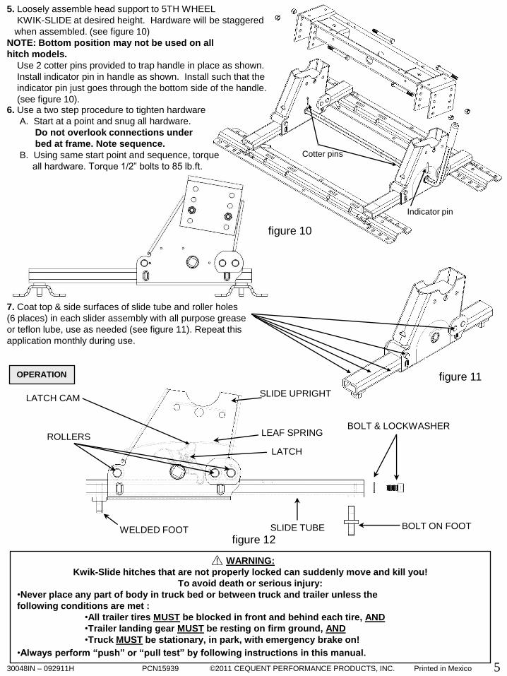
7. Lubricate yokes (37) in head support with heavy oil.
8. Install outer tubular handle (35) over solid inner handle (17) and pin together with cotter pin (34). Bend cotter pin to
hold in place. Check that latch bolt (19) is snug. Do not over tighten (latch (18) must be able to move with firm
hand effort). Check to see that all snap rings (16) are in place.
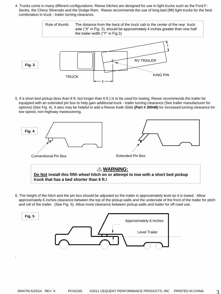
9. Install rubber stopper (42) onto head support (27) using #8 machine screws and #8 nuts. Install one stopper on the
right side of head support and one on the left. See figure 10 on page 6 for details.
10. Place head assembly (26) into head support (27) and secure with pivot pin (30). Insert klik-pin (31) into pivot pin
(30).
WARNING: Failure to follow this instruction may result in king pin being too high and coming to rest on top of closed jaws or
not completely inside jaws. (See Fig. 9). This could result in trailer separating from hitch. Trailer separation may
result in death or serious injury if anyone is under the trailer or between truck and trailer when separation occurs.
30047IN-5/23/14 REV. K PCN2165 ©2011 CEQUENT PERFORMANCE PRODUCTS, INC PRINTED IN CHINA
6
#8 screw here with
rubber stopper and nut
Fig. 10

30047IN-5/23/14 REV. K PCN2165 ©2011 CEQUENT PERFORMANCE PRODUCTS, INC PRINTED IN CHINA
7
3. Rotate latch (see Fig. 11) toward trailer and free of groove in handle. NOTE: Hitch jaws will not open and proper hitching
cannot occur if latch is in handle groove.
Fig. 11 Latch
King pin
Groove in Handle Hitch Jaws
4. With handle in the closed position (See Fig. 11), back truck slowly into trailer. As the trailer king pin enters the
hitch it will push the hitch jaws open and extend the handle (See Fig. 12). As king pin completely enters head, jaws
will spring closed around king pin and handle will return to the closed position. (See Fig. 13)
5. Use only the method described above for hitching.
WARNING: Do not attempt to hitch by using trailer jacks to lower trailer and king pin. This could result in king pin
coming to rest on top of skid plate instead of within hitch opening where jaws are located. King pin could
slide off hitch and trailer could drop, resulting in death or serious injury (See Fig. 14).
King pin Handle motion
Latch open
King pin
Jaws closed
Fig. 13 Fig. 12
Fig. 14
WRONG

30047IN-5/23/14 REV. K PCN2165 ©2011 CEQUENT PERFORMANCE PRODUCTS, INC PRINTED IN CHINA
8
6. With all trailer wheels still firmly blocked, landing gear still resting on firm ground and supporting trailer weight, and
truck stationary and in park with emergency brake on: visually check that bottom of pin box is resting on top of the
hitch. THERE SHOULD BE NO SPACE BETWEEN THESE SURFACES (See Fig. 15). If space exists, (See Fig. 16)
trailer has not been properly hitched. DO NOT TOW! Instead, repeat above steps until trailer is properly hitched.
DO NOT PLACE BODY UNDER TRAILER TO PERFORM THIS INSPECTION!
Fig. 16
WRONG Fig. 15
CORRECT
High Pin No Space
7. Rotate latch for hitch handle to closed position in groove of handle to be sure hitch jaws are locked closed. IF LATCH
IS NOT ALIGNED WITH GROOVE IN HANDLE, TRAILER HAS NOT BEEN PROPERLY CONNECTED TO HITCH.
DO NOT TOW! Repeat above steps until trailer is properly hitched. (See Fig. 17)
King Pin
Jaws closed
Fig. 17
Latch closed
8. With:
•All trailer wheels still firmly blocked in front and behind each tire, and
•Truck stationary with the emergency brake on, and
•Trailer landing gear still resting on firm ground and supporting trailer weight; and
•Truck stationary and with emergency brake on:
Connect electrical cable between truck and trailer, connect breakaway switch cable from pin box to a permanent
part of truck, and raise tailgate of truck.
WARNING WHENEVER POSSIBLE, AVOID PUTTING BODY UNDER TRAILER OR BETWEEN TRUCK AND
TRAILER
If you need to place any part of your body under trailer or between truck and trailer:
All trailer tires MUST be blocked in front and behind each tire AND
Trailer landing gear MUST be resting on firm ground AND
Truck MUST be stationary, in park, with emergency brake on!
30047IN-5/23/14 REV. K PCN2165 ©2011 CEQUENT PERFORMANCE PRODUCTS, INC PRINTED IN CHINA
9
1. With:
•All trailer wheels still firmly blocked, and
•Trailer land gear still resting on firm ground and supporting trailer weight and,
•Truck stationary and with emergency brake on:
Return to cab of truck and release truck’s emergency brake. Apply trailer brakes. After making sure no one is between
truck and trailer, try to pull trailer slowly forward with the truck. If the trailer is properly hitched, the wheel blocks and trailer
brakes should keep the truck from moving forward.
NOTE: If trailer is not properly hitched, trailer will separate from hitch and truck will move forward leaving trailer behind. If
the trailer landing gear is still on resting on firm ground supporting trailer weight and wheels are blocked, trailer will
not be able to drop or fall
2. After successfully performing above steps, fully raise trailer landing gear (see trailer manual).
3. Check and inspect all electrical circuits for proper operation. (Clearance lights, turn signals, stop lights, etc.).
4. Remove and store all trailer wheel blocks.
PERFORM THE FOLLOWING IN THIS ORDER:
1. Place blocks firmly against front and rear of each trailer wheel to prevent any possible forward or rearward motion.
2. Using trailer jacks, lower trailer landing gear following the directions in the Trailer Manual until feet of landing gear are
resting on firm ground.
3. Make sure truck is in park with the emergency brake on.
UNHITCHING PROCEDURE:
PULL TEST
WARNING: Failure to keep wheels blocked and landing gear down could result in trailer suddenly moving or
falling. This could result in death or serious injury!
WARNING:
Failure to perform this test may result in death or serious injury!
WARNING:
Trailers that are not stable or properly hitched can fall and kill you! To avoid death or
serious injury:
• All trailer tires MUST be blocked in front and behind each tire AND
• Trailer landing gear MUST be resting on firm ground AND
• Truck MUST be stationary, in park, with emergency brake on!
4. Lower truck tail gate.
5. Disconnect power cable and breakaway switch cable between truck and trailer.
6. Rotate latch for hitch handle toward trailer and free of groove in handle. (Fig. 17 on next page)
7. Pull hitch handle out completely until it latches in open position so that king pin is no longer
securely grasped by hitch jaws (See Fig. 19 on next page). Trailer is now free from hitch and
truck. If handle does not pull out, there is probably pressure against the jaws. To relieve this
pressure, back the truck slightly. Reset truck emergency brake. Then pull hitch handle out
completely until it latches in open position. (See Fig. 19)

30047IN-5/23/14 REV. K PCN2165 ©2011 CEQUENT PERFORMANCE PRODUCTS, INC PRINTED IN CHINA
10
8. AFTER MAKING CERTAIN NO ONE IS STANDING BETWEEN TRUCK AND TRAILER OR IN FRONT OF TRUCK,
drive truck slowly away from trailer.
9. Close hitch jaws by pushing handle forward and up.
(Spring will close jaws.)
10. KEEP WHEEL BLOCKS IN PLACE. This will keep trailer from moving unexpectedly
1. Recheck tightness of all hardware every 1000 miles of use.
2. See “Before each trip” section in this manual.
Part No:___________________________________________ Date of Original Purchase:_________________________________________________
Original Owner:_____________________________________ Original Installer:________________________________________________________
1. Limited Lifetime Warranty (“Warranty”). Cequent Performance Products, Inc. ("We" or “Us”) warrants to the original consumer purchaser only
("You") that the product will be free from material defects in both material and workmanship, ordinary wear and tear excepted; provided that installation
and use of the product is in accordance with product instructions. There are no other warranties, express or implied, including the warranty of
merchantability or fitness for a particular purpose. This warranty is not transferable.
2. Limitations on the Warranty. This Warranty does not cover: (a) normal wear and tear; (b) damage through abuse, neglect, misuse, or as a result of any
accident or in any other manner; (c) damage from misapplication, overloading, or improper installation; (d) improper maintenance and repair; and (e)
product alteration in any manner by anyone other than Us, with the sole exception of alterations made pursuant to product instructions and in a
workmanlike manner.
3. Obligations of Purchaser. To make a Warranty claim, contact Us, at our principal address of 47912 Halyard Dr. Suite 100, Plymouth, MI 48170, 1-888-
521-0510, identify the product by model number, and follow the claim instructions that will be provided. Any returned product that is replaced by Us
becomes our property. You will be responsible for return shipping costs. Please retain your purchase receipt to verify date of purchase and that You are the
original consumer purchaser. The product and the purchase receipt must be provided to Us in order to process Your Warranty claim.
4. Remedy Limits. Product replacement is Your sole remedy under this Warranty. We shall not be liable for service or labor charges incurred in removing
or replacing a product or any incidental or consequential damages of any kind.
5. Assumption of Risk. You acknowledge and agree that any use of the product for any purpose other than the specified use(s) stated in the product
instructions is at Your own risk.
6. Governing Law. This Warranty gives You specific legal rights, and You also may have other rights which vary from state to state. This Warranty is
governed by the laws of the State of Michigan, without regard to rules pertaining to conflicts of law. The state courts located in Oakland County, Michigan
shall have exclusive jurisdiction for any disputes relating to this Warranty.
MAINTENANCE:
Fig. 19
Pull Handle all the way out
Fig. 18
Latch
Hitch Jaws
Groove in Handle
LIMITED LIFETIME WARRANTY
Groove in Handle
WARNING Whenever possible, avoid putting body under trailer or between truck and trailer
If you need to place any part of our body under trailer or between truck and trailer:
All trailer tires MUST be blocked in front and behind each tire AND
Trailer landing gear MUST be resting on firm ground AND
Truck MUST be stationary, in park, with emergency brake on!
Cequent Performance Products, Inc.
47912 Halyard Dr. Suite 100
Plymouth, MI 48170

30047IN-5/23/14 REV. K PCN2165 ©2011 CEQUENT PERFORMANCE PRODUCTS, INC PRINTED IN CHINA
1
2
3
4
5
6
7
8
9
10
25
11
12
13
14
15
16
17
18
19
20
21
26
27
28
29
3031
32
33
35
33
37
38
39
40
41
42
36
34
11
16K 5TH WHEEL PCS.
11. LONG PULL PIN (4)
12. SPRING RETAINING PIN(4)
13. L.H. JAW (1)
14. R.H. JAW (1)
15. PIN (2)
16. RETAINER RINGS (6)
17. ACTUATING HANDLE (1)
18. LATCH (1)
19. 3/8” BOLT (1)
20. 3/8” FLAT WASHER (1)
21.3/8” LOCK NUT (1)
22.SPRINGS (2)
26. HEAD ASSEMBLY (1)
27. HEAD SUPPORT (1)
28. SIDE BRACKETS (2)
29. PIVOT BEAM (1)
30. PIVOT PIN (1)
31. KLIK-PIN (1)
32. 1/2-13” X4 1/2” BOLTS (4)
33. 1/2” LOCK NUTS (4)
34. COTTER PIN (1)
35. HANDLE, TUBE (1)
36. HANDLE GRIP (1)
42. RUBBER STOPPER (2)
Fig. 20
SEPARATE BASERAIL KIT
PART #30035 QTY.
1. LONG BRACKET (2)
2. SHORT BRACKET (2)
3. FILLER SPACER (10)
4. SPACER (2)
5. CARRIAGE BOLTS (10)
6. KNURLED BOLTS (8)
7. 1/2” NUTS (18)
8. 1/2” LOCKWASHERS (18)
9. 1/2” SERRATED WASHERS (6)
10. 1/2” FLAT WASHERS (4)
14. 4 1/2” CARRIAGE BOLT (2)
15. TUBE SPACER (2)
25. BASERAILS (2)

30048IN – 092911H PCN15939 ©2011 CEQUENT PERFORMANCE PRODUCTS, INC. Printed in Mexico
PLYMOUTH, MI
(OVER)
FOR USE WITH
30048
Handle
Elbow
figure 1
Handle
Shaft
(1) Provide this Manual to end user.
(2) Physically demonstrate sliding procedures in this Manual to end user.
(3) Have end user demonstrate that he/she understands procedures.
(1) Read and follow this Manual every time you use this Kwik Slide.
(2) Save this Manual for future reference.
(3) Pass on copies of Manual to any other user or owner of a Kwik Slide.
(4) Never remove Kwik Slide warning decal as shown on the cover of this manual. If damaged, contact Cequent Towing
Products (1-888-521-0510) for free replacement decals.
DEALER/INSTALLER:
END USER:
INSTRUCTION MANUAL
Kwik Slide
Right hand slide assembly
Warning label
Left hand slide assembly
Indicator pin
Cotter pin
Cequent Towing Products

30048IN – 092911H PCN15939 ©2011 CEQUENT PERFORMANCE PRODUCTS, INC. Printed in Mexico
2
Acceptable King Pin Location
1. 5th wheel trailers are typically designed for use with long bed (8 foot) trucks. These trucks provide ample turning
clearance between the truck cab and trailer front. Short bed trucks (less than 8 ft. but longer than 6 ft.) require
additional turning clearance to avoid truck cab or trailer damage during normal turns. This is best accomplished
through the use of a trailer pin box extension (see figure 2). Cequent Towing Products suggest the use of a
minimum of a 13 inch pin box extension to be able to comfortably make normal turning maneuvers with a short
bed truck. Contact your trailer manufacturer for pin box extension options.
2. The 5TH WHEEL KWIK SLIDE is designed to be used with Cequent Towing Products 5TH WHEEL installations
only. These installations are described in the Cequent Towing Products INSTALLATION INSTRUCTIONS BASE
RAIL MOUNTING KIT (P/N 30035). These instructions specify the exact placement of the base rails in relation to
the rear truck axle for most current pickup trucks.
3. The trailer king pin should always be directly above or slightly forward of the rear truck axle when towing. Trailers
should never be towed with the trailer king pin rearward of the rear truck axle in highway conditions (see Fig. 3).
WARNING:
Failure to follow these instructions may result in death or serious injury!
BEFORE INSTALLATION
figure 2 Trailer Pin Box Extension Conventional Pin Box
CAUTION:
Turning clearance is reduced when towing with a short bed truck! This can result in
trailer striking inside of truck bed. Always monitor truck cab and trailer clearance
during turns. Failure to do so could result in significant property damage.
WARNING:
Kwik-Slide hitches that are not properly locked can suddenly move and kill you!
To avoid death or serious injury:
•Never place any part of body in truck bed or between truck and trailer unless the
following conditions are met :
•Truck is in park with emergency brake on, and
•Trailer landing gear is down and resting on firm ground, and
•All trailer wheels are blocked on each side of wheel
•Always perform “push” or “pull test” by following instructions in this manual.
figure 3
Rear Truck Axle
Unacceptable King Pin Location

30048IN – 092911H PCN15939 ©2011 CEQUENT PERFORMANCE PRODUCTS, INC. Printed in Mexico
3
In this figure, the Kwik-Slide is positioned in the
Towing Position, forward of the rear axle.
Note that a 13-1/2" pin box extension has been
used. This is the only position you should use
when towing!
In this figure, the Kwik-Slide is positioned in the
Maneuvering Position. Note that a 13-1/2" pin
box extension has been used. The maneuvering
Position should only be used at a low speed,
when high maneuverability is needed!
5. Due to the heavy duty nature of the 5TH WHEEL KWIK-SLIDE assembly, the assembly may not
slide by hand when installed, especially if base rails are not securely installed to be parallel and centered.
Rails should be installed so that the center lines of each rail are 21.94 inches (21 15/16”) apart (see figure 6).
Diagonal dimensions "x" and "y” (as depicted in figure 6) should be within 0.1 inch (1/8”) of each other.
If this alignment is not met, loosen hardware and realign base rails. Retorque hardware per
instructions after base rails are properly aligned.
6. Drill 2 holes identified in figure 6 (check for obstructions). Drill all holes with 3/16” drill and enlarge them with a
17/32” drill. Always use sharp drill bits. Install 1/2” carriage bolts into holes. Install slotted spacer above or
below bed to fill corrugations in bed floor, also add bolt plate below bed with washers and nut. These bolts are
in addition to the 8 bolts used when installing base rails according to instructions 30035.
4. The 5TH WHEEL KWIK SLIDE provides additional turning clearance for low speed, off-highway
maneuvering such as backing a RV trailer into a tight camp site. This is done by sliding the hitch 10 inches
rearward of its normal Towing Position (figure 4) to a Maneuvering Position (figure 5). This places the trailer
king pin behind the rear truck axle.
WARNING:
Never tow trailers in highway or high speed conditions with KWIK-SLIDE in the
Maneuvering Position (rearward of the rear axle)! Towing with the trailer king pin
rearward of rear truck axle can affect weight distribution and may interfere with
the towing vehicle’s handling and response characteristics. Poor handling and
response characteristics could result in death or serious injury.
figure 6
Base rails in truck bed, (25) IN 30046 & 30047 instruction manual
X Y
figure 4
Rear Axle
Rear Axle
figure 5
KING PIN
CENTER
KING PIN
CENTER
Add bolt (hardware supplied)
Add bolt (hardware supplied)
Optional bolt
positions, if
obstructed.

30048IN – 092911H PCN15939 ©2011 CEQUENT PERFORMANCE PRODUCTS, INC. Printed in Mexico
4
Reference label
facing driver side.
3. Before setting the 5TH WHEEL KWIK-SLIDE into
the bed of the pickup, attach handle shaft to handle
elbow (see figure 1 on first page). Insert handle
assembly through left hand slide assembly
(driver’s side of towing vehicle) and then through the
right hand side slide assembly (see figure 8).
If 5TH WHEEL KWIK-SLIDE is being used with the
PRO-SERIES 15k head assembly insert handle
through right hand slide assembly (passenger side of
towing vehicle) and then through left hand side of
slide assembly.
4. Set the 5TH WHEEL KWIK-SLIDE into
base rails and pin in position with the
KWIK-SLIDE in the middle of the tubes (see
figure 9).
figure 9
figure 8
2. Before installing 5TH WHEEL KWIK-SLIDE,
leaf spring must be greased as shown using
white lithium grease or equivalent (see figure 7). For
best results, use aerosol white lithium grease with a
spray nozzle extension. Make sure entire
underside of spring is coated! Repeat this application
monthly during use.
1. These instructions should be used to mount 5TH WHEEL KWIK-SLIDE. Care and attention to detail will ensure a
quick, safe and quality installation. Check parts against figure 1 to become familiar with kit.
INSTALLATION
WARNING:
Pull pin spring clips must
be on the outside of base rail
as shown. Spring clips
installed on the inside of
base rail will not allow Kwik-
Slide to slide far enough to
lock. Kwik-Slides that are
not properly locked can
suddenly move and cause
serious injury or death.
Slide Tube
Kwik Slide Upright
Aerosol white lithium
grease spray with nozzle
extension
Leaf spring
figure 7
See figure 10 for
installed clip locations.
30048IN – 092911H PCN15939 ©2011 CEQUENT PERFORMANCE PRODUCTS, INC. Printed in Mexico
5
5. Loosely assemble head support to 5TH WHEEL
KWIK-SLIDE at desired height. Hardware will be staggered
when assembled. (see figure 10)
NOTE: Bottom position may not be used on all
hitch models.
Use 2 cotter pins provided to trap handle in place as shown.
Install indicator pin in handle as shown. Install such that the
indicator pin just goes through the bottom side of the handle.
(see figure 10).
figure 12
7. Coat top & side surfaces of slide tube and roller holes
(6 places) in each slider assembly with all purpose grease
or teflon lube, use as needed (see figure 11). Repeat this
application monthly during use.
figure 11
figure 10
6. Use a two step procedure to tighten hardware
A. Start at a point and snug all hardware.
Do not overlook connections under
bed at frame. Note sequence.
B. Using same start point and sequence, torque
all hardware. Torque 1/2” bolts to 85 lb.ft.
Cotter pins
Indicator pin
WARNING:
Kwik-Slide hitches that are not properly locked can suddenly move and kill you!
To avoid death or serious injury:
•Never place any part of body in truck bed or between truck and trailer unless the
following conditions are met :
•All trailer tires MUST be blocked in front and behind each tire, AND
•Trailer landing gear MUST be resting on firm ground, AND
•Truck MUST be stationary, in park, with emergency brake on!
•Always perform “push” or “pull test” by following instructions in this manual.
ROLLERS
WELDED FOOT
LATCH
SLIDE TUBE BOLT ON FOOT
SLIDE UPRIGHT
LEAF SPRING BOLT & LOCKWASHER
LATCH CAM
OPERATION

30048IN – 092911H PCN15939 ©2011 CEQUENT PERFORMANCE PRODUCTS, INC. Printed in Mexico
6
Leaf spring on latch cam keeps latch from
disengaging. Hitch can not move rearward with
latch engaged. Rearward load forces latch further
into slot. Hitch can not move forward due to
welded foot (see figures 1, 11 and 12).
FRONT OF TOW VEHICLE TOWING POSITION figure 13
1. Position truck and trailer in a straight line on a flat, level area.
2. Place truck in “Park” with emergency brake “on”.
3. Block front and back of all trailer wheels.
4. Lower trailer landing gear so it is resting on firm ground.
5. Pull handle forward (see figure 14). Indicator pin should be
over red unlocked range near the green locked maneuvering
range (see figure 14).Spring pressure will press latch against
top of tube, the latch will lock into slot when the 5TH WHEEL
KWIK-SLIDE moves to the maneuvering position (see figure 15).
6. Return to truck. Release emergency brake. Manually engage
trailer brake and pull truck forward until 5TH WHEEL KWIK
SLIDE stops at bolt in foot (figure 12) and latch engages in
maneuvering position (see figure 15).
MOVE TO MANEUVERING POSITION Figure 14
7. Perform “PUSH TEST” as follows:
1. Manually engage trailer brakes from truck cab.
2. Back truck into trailer against trailer wheel blocks.
3. If Kwik-Slide does not move, latch has engaged tubes
and Kwik-Slide should be locked in maneuvering position.
4. If Kwik-Slide does move, latch has not engaged tubes.
DO NOT TOW!. Repeat steps 1 - 7 above.
8. Again, place truck in “Park” with emergency brake “on”.
9. Examine warning label. Indicator pin should now be over the green range
on the left side of the warning label (see figure 15). If indicator pin is over
red range on warning label, latch has not engaged tubes. DO NOT TOW!
Repeat steps 1- 7 above.
10. After successfully performing above steps, fully raise trailer
landing gear (See trailer manual).
11. Remove and store all trailer wheel blocks.
MOVE FROM TOWING TO MANEUVERING POSITION
MANEUVERING POSITION Figure 15
Indicator pin
Indicator pin
Indicator pin
WARNING:
Kwik-Slide hitches that are not properly locked can suddenly move and kill you!
To avoid death or serious injury:
•Never place any part of body in truck bed or between truck and trailer unless the
following conditions are met :
•All trailer tires MUST be blocked in front and behind each tire, AND
•Trailer landing gear MUST be resting on firm ground, AND
•Truck MUST be stationary, in park, with emergency brake on!
•Always perform “push” or “pull test” by following instructions in this manual.

30048IN – 092911H PCN15939 ©2011 CEQUENT PERFORMANCE PRODUCTS, INC. Printed in Mexico
7
WARNING:
Kwik-Slide hitches that are not properly locked can suddenly move and kill you!
To avoid death or serious injury:
•Never place any part of body in truck bed or between truck and trailer unless the
following conditions are met :
•All trailer tires MUST be blocked in front and behind each tire, AND
•Trailer landing gear MUST be resting on firm ground, AND
•Truck MUST be stationary, in park, with emergency brake on!
•Always perform “push” or “pull test” by following instructions in this manual.
MOVE FROM MANEUVERING TO TOWING POSITION
1. Position truck and trailer in a straight line on a flat, level area.
2. Place truck in “Park” with emergency brake “on”.
3. Block front and back of all trailer wheels.
4. Lower trailer landing gear so it is resting on firm ground.
5. Push handle rearward (see figure 16). Indicator pin should be
over red unlocked range near the green locked towing
range (see figure 16).Spring pressure will press latch against
top of tube, the latch will lock into slot when the 5TH WHEEL
KWIK-SLIDE moves to the towing position (see figure 17).
6. Return to truck. Release emergency brake. Manually engage
trailer brake and back truck rearward until 5TH WHEEL KWIK
SLIDE stops at the welded foot (figure 12) and latch engages in
towing position (see figure 17).
7. Perform “PULL TEST” as follows:
1. Manually engage trailer brakes from truck cab.
2. Pull truck and trailer forward against trailer wheel blocks.
3. If Kwik-Slide does not move, latch has engaged tubes
and Kwik-Slide should be locked in towing position.
4. If Kwik-Slide does move, latch has not engaged tubes.
DO NOT TOW!. Repeat steps 1 - 7 above.
8. Again, place truck in “Park” with emergency brake “on”.
9. Examine warning label. Indicator pin should now be over the green range
on the right side of the warning label (see figure 17). If indicator pin is
over red range on warning label, latch has not engaged tubes. DO NOT
TOW! Repeat steps 1- 7 above.
10. After successfully performing above steps, fully raise trailer
landing gear (See trailer manual).
11. Remove and store all trailer wheel blocks.
MOVE TO TOWING POSITION
FRONT OF TOW VEHICLE
Figure 16
TOWING POSITION
Indicator pin
Figure 17
Indicator pin
Part No:____________________________________________________ Date of Original Purchase:________________________________________
Original Owner:______________________________________________ Original Installer:_______________________________________________
1. Limited Lifetime Warranty (“Warranty”). Cequent Performance Products, Inc. ("We" or “Us”) warrants to the original consumer purchaser only ("You") that the
product will be free from material defects in both material and workmanship, ordinary wear and tear excepted; provided that installation and use of the product is in
accordance with product instructions. There are no other warranties, express or implied, including the warranty of merchantability or fitness for a particular purpose. This
warranty is not transferable.
2. Limitations on the Warranty. This Warranty does not cover: (a) normal wear and tear; (b) damage through abuse, neglect, misuse, or as a result of any accident or
in any other manner; (c) damage from misapplication, overloading, or improper installation; (d) improper maintenance and repair; and (e) product alteration in any manner
by anyone other than Us, with the sole exception of alterations made pursuant to product instructions and in a workmanlike manner.
3. Obligations of Purchaser. To make a Warranty claim, contact Us, at our principal address of 47912 Halyard Dr. Suite 100, Plymouth, MI 48170, 1-888-521-0510,
identify the product by model number, and follow the claim instructions that will be provided. Any returned product that is replaced by Us becomes our property. You will
be responsible for return shipping costs. Please retain your purchase receipt to verify date of purchase and that You are the original consumer purchaser. The product
and the purchase receipt must be provided to Us in order to process Your Warranty claim.
4. Remedy Limits. Product replacement is Your sole remedy under this Warranty. We shall not be liable for service or labor charges incurred in removing or replacing a
product or any incidental or consequential damages of any kind.
5. Assumption of Risk. You acknowledge and agree that any use of the product for any purpose other than the specified use(s) stated in the product instructions is at
Your own risk.
6. Governing Law. This Warranty gives You specific legal rights, and You also may have other rights which vary from state to state. This Warranty is governed by the
laws of the State of Michigan, without regard to rules pertaining to conflicts of law. The state courts located in Oakland County, Michigan shall have exclusive jurisdiction
for any disputes relating to this Warranty.
LIMITED LIFETIME WARRANTY
Cequent Performance Products, Inc.
47912 Halyard Dr. Suite 100
Plymouth, MI 48170