Embed Size (px)
Citation preview
INSTRUCTIONS–PARTS LIST 308–464Rev. B
Supersedes A
30:1 PRESIDENT CARBON STEEL, WALL MOUNTED
PRO AA4500 Electrostatic PackageSee the Data Sheet, 305–668, for application information.
3000 psi (210 bar) Maximum System Working Pressure100 psi (6.9 bar) Maximum Air Inlet Pressure
Model 237–425, Series AThis complete package includes a pump,electrostatic air-assisted airless gun with a size 411 tip,wall bracket, 25 ft. (7.6 m) air and fluid hoses, air and fluid controls, and a fluid feed.
IMPORTANTThis manual provides the basic safety, installation andoperation information for the package. For your safety,also read the component manuals supplied with thispackage before operating it.
GRACO INC. P.O. BOX 1441 MINNEAPOLIS, MN 55440–1441�COPYRIGHT 1994, GRACO INC.
This manual contains important warnings and information. READ AND RETAIN FOR REFERENCE
�����
� �������
Table of ContentsSymbols 2. . . . . . . . . . . . . . . . . . . . . . . . . . . . . . . . . . . . . . Warnings 3. . . . . . . . . . . . . . . . . . . . . . . . . . . . . . . . . . . . . . Setup 5. . . . . . . . . . . . . . . . . . . . . . . . . . . . . . . . . . . . . . . . .
Ground the system 7. . . . . . . . . . . . . . . . . . . . . . . . . . . System Component Information 9. . . . . . . . . . . . . . . . . . Operation 10. . . . . . . . . . . . . . . . . . . . . . . . . . . . . . . . . . . .
Pressure relief procedure 10. . . . . . . . . . . . . . . . . . . . . Flushing 13. . . . . . . . . . . . . . . . . . . . . . . . . . . . . . . . . . . . . Parts 14. . . . . . . . . . . . . . . . . . . . . . . . . . . . . . . . . . . . . . . . Technical Data 16. . . . . . . . . . . . . . . . . . . . . . . . . . . . . . . . Warranty 16. . . . . . . . . . . . . . . . . . . . . . . . . . . . . . . . . . . . . Graco Phone Numbers 16. . . . . . . . . . . . . . . . . . . . . . . . .
SymbolsWarning Symbol
WARNINGThis symbol alerts you to the possibility of seriousinjury or death if you do not follow the instructions.
Caution Symbol
CAUTIONThis symbol alerts you to the possibility of damage toor destruction of equipment if you do not follow thecorresponding instructions.
WARNINGWARNING
FIRE, EXPLOSION AND ELECTROSTATIC SHOCK HAZARDImproper grounding, poor air ventilation, open flames or sparks can cause a hazardous conditionand result in a fire, explosion or electrostatic shock and other serious injury.
� Electrostatic equipment must be used only by trained, qualified personnel who shall be under-stand with the requirements stated in this instruction manual and the electrostatic gun manual.
� Ground the equipment, the object being sprayed and all other electrically conductive objects inthe spray area. Proper grounding dissipates static electricity generated in the equipment. SeeGround the system on 7.
� If there is any static sparking while using the equipment, stop spraying immediately . Identifyand correct the problem.
� When flushing or purging electrostatic equipment, use solvents with a flash point equal to orgreater than that of the fluid being sprayed.
� To clean the exterior of the electrostatic equipment, use solvents with a flash point higher than100� F (38�� C).
� Remove all solvent from the system before reactivating the electrostatic spray gun.
� Use only non-sparking tools to clean residue from the booth and hangers.
� Spray only in a ventilated spray booth. Electrically interlock the gun air supply with the ventilatorsto prevent operation of the electrostatic power supply unless ventilating fans are running.
� Do not smoke in the spray area.
� Extinguish all open flames or pilot lights in the spray area.
� Do not turn on or off any light switch in the spray area.
� Electrically disconnect all equipment in the spray area.
� Keep the spray area free of debris, including solvent, rags and gasoline.
� Do not operate a gasoline engine in the spray area.
��������
WARNINGWARNING
FLUID INJECTION HAZARDSpray from the gun, hose leaks or ruptured components can inject fluid into your body and causeextremely serious injury, including the need for amputation. Splashing fluid in the eyes or on the skincan also cause can also cause serious injury.
� Fluid injected into the skin is a serious injury. The injury might look like just a cut, but it is a seri-ous injury. Get immediate medical attention.
� Do not point the spray gun at anyone or any part of the body.
� Do not put hand or fingers over the spray tip.
� Do not stop or deflect fluid leaks with your hand, body, glove or rag.
� Do not “blow back” fluid; this is not an air spray system.
� Always have the tip guard and the trigger guard on the spray gun when spraying.
� Check the gun diffuser operation weekly. Refer to the gun manual.
� Be sure the gun trigger safety operates before spraying the gun.
� Lock the gun trigger safety when you stop spraying.
� Follow the Pressure relief procedure on page 10 if the spray tip clogs and before cleaning,checking or servicing the equipment.
� Tighten all fluid connections before each use.
� Check the hoses, tubes and couplings daily. Replace worn or damaged parts immediately. Per-manently coupled hoses cannot be repaired.
� Handle and route hoses and tubes carefully. Keep hoses and tubes away from moving parts andhot surfaces. Do not use the hoses to pull equipment. Do not expose Graco hoses to tempera-tures above 180�F (82�C) or below –40�F (–40�C).
MOVING PARTS HAZARDMoving parts, such as the air motor piston, which can pinch or amputate fingers.
� Never operate the equipment with the air motor plates removed.
� Keep clear of any moving parts when starting or operating the equipment.
� �������
WARNINGWARNING
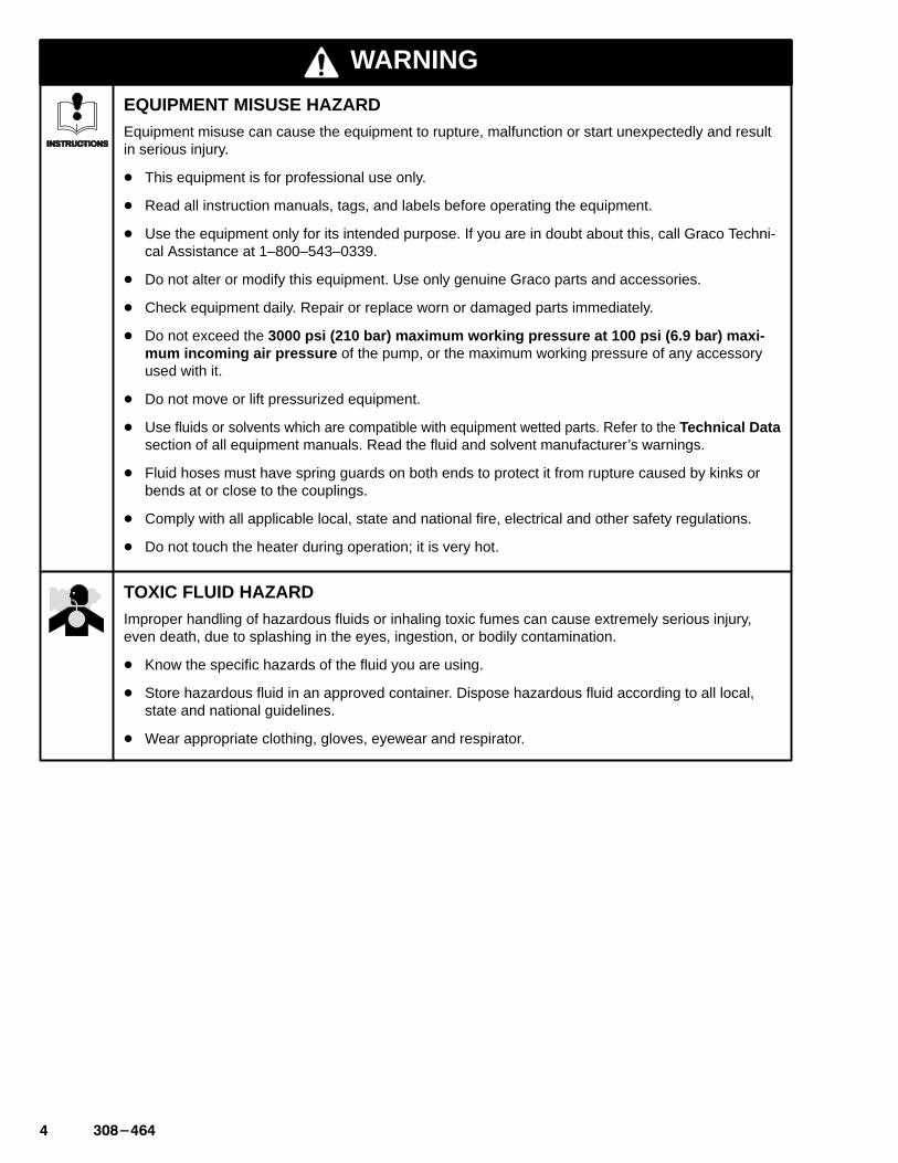
EQUIPMENT MISUSE HAZARDEquipment misuse can cause the equipment to rupture, malfunction or start unexpectedly and resultin serious injury.
� This equipment is for professional use only.
� Read all instruction manuals, tags, and labels before operating the equipment.
� Use the equipment only for its intended purpose. If you are in doubt about this, call Graco Techni-cal Assistance at 1–800–543–0339.
� Do not alter or modify this equipment. Use only genuine Graco parts and accessories.
� Check equipment daily. Repair or replace worn or damaged parts immediately.
� Do not exceed the 3000 psi (210 bar) maximum working pressure at 100 psi (6.9 bar) maxi -mum incoming air pressure of the pump, or the maximum working pressure of any accessoryused with it.
� Do not move or lift pressurized equipment.
� Use fluids or solvents which are compatible with equipment wetted parts. Refer to the Technical Datasection of all equipment manuals. Read the fluid and solvent manufacturer’s warnings.
� Fluid hoses must have spring guards on both ends to protect it from rupture caused by kinks orbends at or close to the couplings.
� Comply with all applicable local, state and national fire, electrical and other safety regulations.
� Do not touch the heater during operation; it is very hot.
TOXIC FLUID HAZARDImproper handling of hazardous fluids or inhaling toxic fumes can cause extremely serious injury,even death, due to splashing in the eyes, ingestion, or bodily contamination.
� Know the specific hazards of the fluid you are using.
� Store hazardous fluid in an approved container. Dispose hazardous fluid according to all local,state and national guidelines.
� Wear appropriate clothing, gloves, eyewear and respirator.
��������
SetupI. Prepare the operator.All persons who operate the system should be trainedin the safe, efficient operation of all system compo-nents as well as the proper handling of the chemicalcoating. At a minimum, all operators should thoroughly read the safety, installation and operationsections of this manual and the component manuals.
II. Prepare the site.1. Use a minimum recommended 7 HP (5.8 kW) air
compressor for efficient operation.
2. Clear obstacles and debris that could hinder theoperator’s movement.
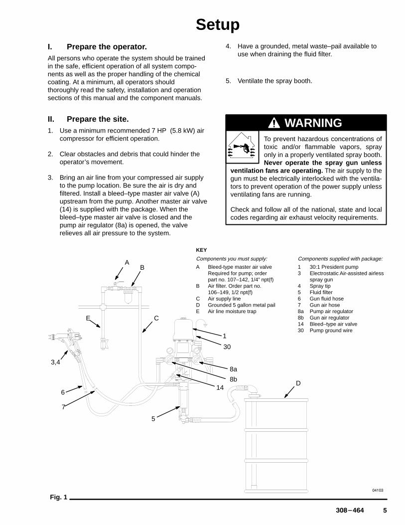
3. Bring an air line from your compressed air supplyto the pump location. Be sure the air is dry andfiltered. Install a bleed–type master air valve (A)upstream from the pump. Another master air valve(14) is supplied with the package. When thebleed–type master air valve is closed and thepump air regulator (8a) is opened, the valverelieves all air pressure to the system.
4. Have a grounded, metal waste–pail available touse when draining the fluid filter.
5. Ventilate the spray booth.
To prevent hazardous concentrations oftoxic and/or flammable vapors, sprayonly in a properly ventilated spray booth.Never operate the spray gun unless
ventilation fans are operating. The air supply to thegun must be electrically interlocked with the ventila-tors to prevent operation of the power supply unlessventilating fans are running.
Check and follow all of the national, state and localcodes regarding air exhaust velocity requirements.
WARNING
Fig. 1
5
D
30
1
3,4
�����
E
KEY
Components you must supply:
A Bleed-type master air valveRequired for pump; order part no. 107–142, 1/4” npt(f)
B Air filter. Order part no. 106–149, 1/2 npt(f)
C Air supply lineD Grounded 5 gallon metal pailE Air line moisture trap
Components supplied with package:
1 30:1 President pump3 Electrostatic Air-assisted airless
spray gun4 Spray tip5 Fluid filter6 Gun fluid hose7 Gun air hose8a Pump air regulator8b Gun air regulator14 Bleed–type air valve30 Pump ground wire
8b
8a
146
7
AB
C
� �������
SetupIII. Unpack the system.1. In addition to the assembled components, the air
and fluid hoses, gun and instruction manuals arepackaged separately in the main shipping con-tainer. These are the manuals you should receive:
306–981 30:1 ratio President pump308–294 Electrostatic air spray gun307–273 Fluid filter308–167 Air regulator308–861 Ball valve
2. Mount the gun mounting bracket on the wall. Seethe gun manual 308–294. Use this bracket to holdthe gun nozzle downward when not in use. SeeFig. 8, page 8.
IV. Setup the system.1. Be sure the wall where you plan to mount the wall
bracket can support the weight of the system andthe stress caused during pump operation.
2. Remove the paper backing from the mountingtemplate, supplied. Apply the template to the wall,4 to 5 feet (1.2 to 1.6 m) above the floor. Drill theholes. The bolt holes are 0.48 inches (12 mm) indiameter. Remove the template. Mount the pumpsecurely.
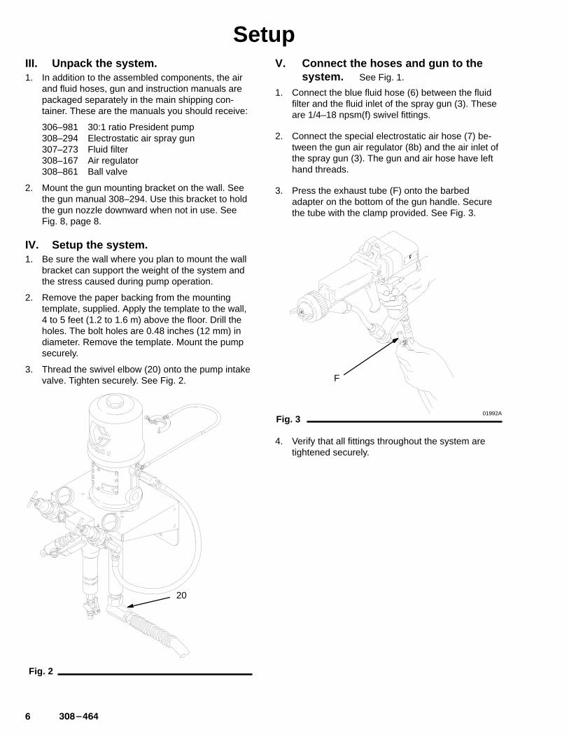
3. Thread the swivel elbow (20) onto the pump intakevalve. Tighten securely. See Fig. 2.
Fig. 2
20
V. Connect the hoses and gun to thesystem. See Fig. 1.
1. Connect the blue fluid hose (6) between the fluidfilter and the fluid inlet of the spray gun (3). Theseare 1/4–18 npsm(f) swivel fittings.
2. Connect the special electrostatic air hose (7) be-tween the gun air regulator (8b) and the air inlet ofthe spray gun (3). The gun and air hose have lefthand threads.
3. Press the exhaust tube (F) onto the barbedadapter on the bottom of the gun handle. Securethe tube with the clamp provided. See Fig. 3.
Fig. 301992A
F
4. Verify that all fittings throughout the system aretightened securely.
��������
SetupVI. Ground the system.
WARNINGTo reduce the risk of static sparking, ground thepump and all other equipment used or located inthe spray area. Check your local electrical code fordetailed grounding instructions for your area andtype of equipment. Ground all of this equipment.Also read FIRE, EXPLOSION OR ELECTROS-TATIC SHOCK HAZARD on page 2..
1. Pump: one end of the ground wire (30) is alreadyconnected to the air motor grounding lug. Connectthe clamp end of the ground wire to a true earthground.
2. Air and fluid hoses: use only electrically conductivehoses with a maximum of 500 feet (150 m) com-bined hose length to ensure grounding continuity.
3. Air compressor: according to manufacturer’s recommendations.
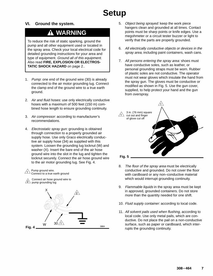
4. Electrostatic spray gun: grounding is obtainedthrough connection to a properly grounded airsupply hose. Use only Graco electrically conduc-tive air supply hose (34) as supplied with thissystem. Loosen the grounding lug locknut (W) andwasher (X). Insert the bare end of the air hoseground wire into the slot in the lug and tighten thelocknut securely. Connect the air hose ground wireto the air motor grounding lug. See Fig. 4.
Fig. 4
�Connect air hose ground wire topump grounding lug
�W
X
30����
�Pump ground wire.Connect to a true earth ground
�
5. Object being sprayed: keep the work piecehangers clean and grounded at all times. Contactpoints must be sharp points or knife edges. Use amegohmeter or a circuit tester buzzer or light toverify that the parts are properly grounded.
6. All electrically conductive objects or devices in thespray area, including paint containers, wash cans.
7. All persons entering the spray area: shoes musthave conductive soles, such as leather, orpersonal grounding straps must be worn. Rubberof plastic soles are not conductive. The operatormust not wear gloves which insulate the hand fromthe spray gun. The gloves must be conductive ormodified as shown in Fig. 5. Use the gun cover,supplied, to help protect your hand and the gunfrom overspray.
Fig. 5
3 in. (76 mm) square cut out and finger of glove cut off
�
�
8. The floor of the spray area must be electricallyconductive and grounded. Do not cover the floorwith cardboard or any non–conductive materialwhich would interrupt grounding continuity.
9. Flammable liquids in the spray area must be keptin approved, grounded containers. Do not storemore than the quantity needed for one shift.
10. Fluid supply container: according to local code.
11. All solvent pails used when flushing, according tolocal code. Use only metal pails, which are con-ductive. Do not place the pail on a non-conductivesurface, such as paper or cardboard, which inter-rupts the grounding continuity.

� �������
System Component InformationVII. How to use the air–assisted airless
electrostatic spray gun. See Fig. 6.
The air hose supplies air to the spray gun. Part of theair operates the turbine and the rest of the air assistsin the atomization of the fluid being sprayed. Theturbine generates power which is converted by thepower cartridge to supply high voltage current to thegun’s ionizing electrode.
The pump supplies fluid to the hose and gun, wherethe fluid is electrostatically charged as it passes theelectrode. The charged fluid is attracted to thegrounded work piece, wrapping around and evenlycoating all surfaces.
The air control valve (C) controls all of the air to thegun air cap.
See Fig. 7 for how to operate the trigger safety latch.
See the gun instruction manual, 308–294, for detailedinformation, including troubleshooting, cleaning andrepair.
Always hang the gun in the gun holder bracket (F),supplied, with the nozzle pointing down. See Fig. 8.This prevents solvent from running into the gun airpassages. Solvent in the gun air passages cancause poor atomization and excessive currentdemands and damage the gun.
CAUTION
Fig. 6
KEY
A ES indicator lightB ES On–Off lever
I is ON and 0 is OFFC Air control valveD ElectrodeE Air cap
BC
D
E
01947
A
Fig. 7
�
�
UNLOCKED trigger safety latch
LOCKED trigger safety latch
�
�
Fig. 8 02010A
C
��������
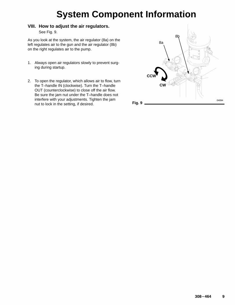
System Component InformationVIII. How to adjust the air regulators.
See Fig. 9.
As you look at the system, the air regulator (8a) on theleft regulates air to the gun and the air regulator (8b)on the right regulates air to the pump.
1. Always open air regulators slowly to prevent surg-ing during startup.
2. To open the regulator, which allows air to flow, turnthe T–handle IN (clockwise). Turn the T–handleOUT (counterclockwise) to close off the air flow.Be sure the jam nut under the T–handle does notinterfere with your adjustments. Tighten the jamnut to lock in the setting, if desired.
�����
Fig. 9
8a
8b
CW
CCW
�� �������
OperationI. Pressure relief procedure
The system remains pressurized until pressure ismanually relieved. To reduce the risk of seriousinjury, including skin injection from pressurized fluidor accidental spray from the gun, or injury due tosplashing fluid in the eyes or on the skin, follow thisprocedure whenever you:
� are told to relieve pressure;� stop spraying;� check or service any system equipment;� install, clean or change spray tips.
WARNING
1. Lock the gun trigger safety.
2. Turn the ES On/Off valve lever to OFF.
3. Close the bleed-type master air valves (A,14).
4. Close the air regulators (8a,8b).
5. Unlock the gun trigger safety.
6. Hold the gun firmly against a grounded metalwaste pail. Trigger the gun to relieve pressure.
7. Lock the gun trigger safety.
8. Open the filter drain valve (26), having a containerready to catch the drainage. Close the drain valve.
If you suspect that the spray tip or hose is completelyclogged or that pressure has not been fully relieved,very slow loosen the tip retaining nut or hose end cou-pling and relieve pressure gradually. Clean the tip orhose obstruction.
II. Flush the pump before the first use.Flush with a solvent compatible to your fluid. Consultthe fluid manufacturer’s literature for recommenda-tions. See Flushing on page 13.
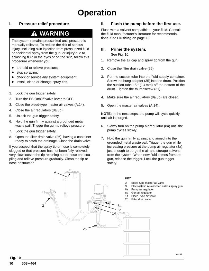
III. Prime the system.See Fig. 10.
1. Remove the air cap and spray tip from the gun.
2. Close the filter drain valve (26).
3. Put the suction tube into the fluid supply container.Screw the bung adapter (35) into the drum. Positionthe suction tube 1/2” (13 mm) off the bottom of thedrum. Tighten the thumbscrew (31).
4. Make sure the air regulators (8a,8b) are closed.
5. Open the master air valves (A,14).
NOTE: In the next steps, the pump will cycle quicklyuntil air is purged.
6. Slowly turn on the pump air regulator (8a) until thepump cycles slowly.
7. Hold the gun firmly against and aimed into thegrounded metal waste pail. Trigger the gun whileincreasing pressure at the pump air regulator (8a)just enough to purge the air and storage solventfrom the system. When new fluid comes from thegun, release the trigger. Lock the gun triggersafety.
Fig. 10�����
KEY
A Bleed-type master air valve3 Electrostatic Air-assisted airless spray gun8a Pump air regulator8b Gun air regulator14 Bleed–type air valve26 Filter drain valve
26
38b8a
14
A
���������
OperationIV. Set the fluid and air pressure.1. Install the spray tip and air cap on the gun.
2. Adjust the pump air pressure regulator until thepressure shown on the fluid filter gauge is about900 psi (63 bar). This should require approximately30 psi (2.1 bar) air pressure to the pump.
3. Test spray a pass or stationary horizontal pattern.Hold the gun 10 to 12 in. (250 to 300 mm) from thepaper. Stripes in the outer edges of the pass orspots at the ends of the stationary pattern arelikely at this point.
NOTE: If there are no stripes or spots, lower thefluid pressure until they appear before turning onthe air to the gun.
4. Partially trigger the gun so only air is emitted. Setthe gun air regulator to 50 psi (3.5 bar).
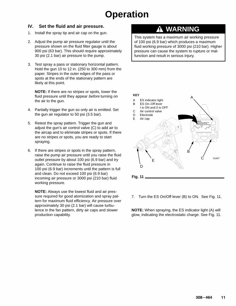
5. Retest the spray pattern. Trigger the gun andadjust the gun’s air control valve (C) to add air tothe aircap and to eliminate stripes or spots. If thereare no stripes or spots, you are ready to startspraying.
6. If there are stripes or spots in the spray pattern,raise the pump air pressure until you raise the fluidoutlet pressure by about 100 psi (6.9 bar) and tryagain. Continue to raise the fluid pressure in100 psi (6.9 bar) increments until the pattern is fulland clean. Do not exceed 100 psi (6.9 bar)incoming air pressure or 3000 psi (210 bar) fluidworking pressure.
NOTE: Always use the lowest fluid and air pres-sure required for good atomization and spray pat-tern for maximum fluid efficiency. Air pressure overapproximately 30 psi (2.1 bar) will cause turbu-lence in the fan pattern, dirty air caps and slowerproduction capability.
WARNINGThis system has a maximum air working pressureof 100 psi (6.9 bar) which produces a maximumfluid working pressure of 3000 psi (210 bar). Higherpressure can cause the system to rupture or mal-function and result in serious injury.
Fig. 11
KEY
A ES indicator lightB ES On–Off lever
I is ON and 0 is OFFC Air control valveD ElectrodeE Air cap
B
C
D
E01947
A
7. Turn the ES On/Off lever (B) to ON. See Fig. 11.
NOTE: When spraying, the ES indicator light (A) willglow, indicating the electrostatic charge. See Fig. 11.
�� �������
Operation8. Hold the gun tip (electrode) (D) 10 to 12 in. (250 to
300 mm) from the grounded part and trigger thegun. Operate the gun like a conventional spraygun, but use a slower stroke to allow the electros-tatics to work properly.
9. When the ES On/Off lever is turned on and youtrigger the gun, be sure there is a grounded workpiece 10 to 12 in. (250 to 300 mm) in front of thegun.
WARNINGNever trigger the gun without a grounded workpiece in front of the gun. If your body is the bestground or if you are holding the gun too far fromthe work piece, the material will be attracted to andcover you instead of the work piece.
10. Use the gun air control valve to adjust the degreeof atomization. Always use the lowest air pressurepossible for the most efficiency.
Using the air control valve may affect the patternsize slightly. Use it primarily to improve atomizationand pattern.
11. A minimum of 40 psi (2.8 bar) air supply isrequired to ensure full voltage from the powersupply. The gun may be operated at a lower inletair pressure, but you will lose some electrostaticwrap efficiency.
V. You are now ready for productionspraying.
CAUTIONWhen using catalyzed fluids, observe the pot lifeas recommended by the fluid manufacturer. Alwaysflush the system before the pot life has expired toprevent dried fluid which may be difficult to cleanout and may damage the system.
VI. When to shut down the system.Shut down the system at the end of the work shift andbefore checking, adjusting, cleaning or repairing thesystem. Always follow the Pressure relief procedureon page 10.
���������
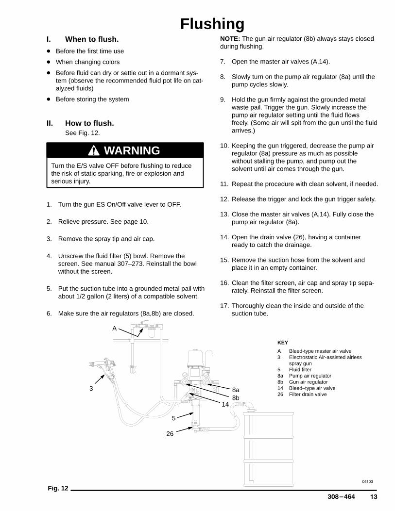
FlushingI. When to flush.� Before the first time use
� When changing colors
� Before fluid can dry or settle out in a dormant sys-tem (observe the recommended fluid pot life on cat-alyzed fluids)
� Before storing the system
II. How to flush.See Fig. 12.
WARNINGTurn the E/S valve OFF before flushing to reducethe risk of static sparking, fire or explosion andserious injury.
1. Turn the gun ES On/Off valve lever to OFF.
2. Relieve pressure. See page 10.
3. Remove the spray tip and air cap.
4. Unscrew the fluid filter (5) bowl. Remove thescreen. See manual 307–273. Reinstall the bowlwithout the screen.
5. Put the suction tube into a grounded metal pail withabout 1/2 gallon (2 liters) of a compatible solvent.
6. Make sure the air regulators (8a,8b) are closed.
NOTE: The gun air regulator (8b) always stays closedduring flushing.
7. Open the master air valves (A,14).
8. Slowly turn on the pump air regulator (8a) until thepump cycles slowly.
9. Hold the gun firmly against the grounded metalwaste pail. Trigger the gun. Slowly increase thepump air regulator setting until the fluid flowsfreely. (Some air will spit from the gun until the fluidarrives.)
10. Keeping the gun triggered, decrease the pump airregulator (8a) pressure as much as possiblewithout stalling the pump, and pump out thesolvent until air comes through the gun.
11. Repeat the procedure with clean solvent, if needed.
12. Release the trigger and lock the gun trigger safety.
13. Close the master air valves (A,14). Fully close thepump air regulator (8a).
14. Open the drain valve (26), having a containerready to catch the drainage.
15. Remove the suction hose from the solvent andplace it in an empty container.
16. Clean the filter screen, air cap and spray tip sepa-rately. Reinstall the filter screen.
17. Thoroughly clean the inside and outside of thesuction tube.
Fig. 12�����
26
3
8b8a
14
A
KEY
A Bleed-type master air valve3 Electrostatic Air-assisted airless
spray gun5 Fluid filter8a Pump air regulator8b Gun air regulator14 Bleed–type air valve26 Filter drain valve
5
�� �������
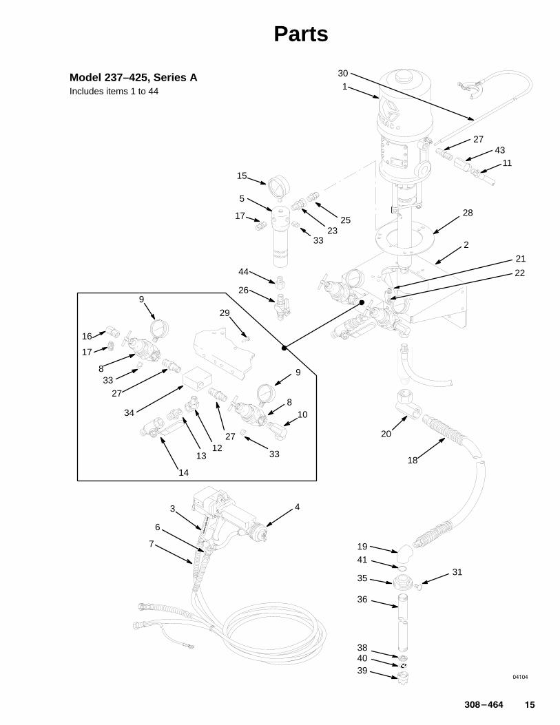
PartsModel 237–425, Series AIncludes items 1 to 44
RefNo. Part No. Description Qty
RefNo. Part No. Description Qty
1 223–586 PRESIDENT PUMPSee 306–981 for parts 1
2 186–727 WALL MOUNTING BRACKET 13 236–030 ELECTROSTATIC AIR–ASSISTED
AIRLESS SPRAY GUNSee manual 307–912 for parts 1
4 GG3–411 FLUID TIP 15 218–029 FLUID FILTER
See 307–273 for parts 16 214–698 FLUID HOSE, cpld 1/4 npsm (fbe)
3/16” ID x 25’ (4.8 mm ID x 7.6 m) 17 237–570 AIR HOSE, electrically conductive
cpld 1/4–18 npsm, 5/16” ID x 25 ft. (7.9 mm ID x 7.6 m) 1
8 104–267 AIR REGULATOR0–125 psi (0–9 bar) rangeSee 308–167 for parts 2
9 101–180 AIR PRESSURE GAUGE0–200 psi (0–14 bar) 2
10 155–470 90� SWIVEL ADAPTER UNION, 1/2 npt(m) x 1/2 npsm(f) swivel 1
11 218–093 AIR HOSE, buna-S, cpld 1/2 npt(mbe), 1/2” ID x 22” (13 mm ID x 559 mm) 1
12 222–297 45� SWIVEL ADAPTER UNION, 1/2 npt(m) x 1/2 npsm(f) swivel 1
13 158–491 NIPPLE, 1/2 npt, 1.625” (41 mm) long 114 107–142 BLEED–TYPE AIR VALVE,
1/2 npt (f) 115 102–814 FLUID PRESSURE GAUGE 116 166–999 ELBOW, reducing street,
1/2 npt(m) x 1/4 npt(f) 117 162–453 NIPPLE, 1/4 npt x 1/4 npsm 218 214–961 SUCTION HOSE, 3/4 npt(mbe),
3/4” ID x 6’ (19 mm ID x 1.82 m) 119 156–591 ELBOW, 3/4 npt (f) 120 156–589 90�� SWIVEL ADAPTER, fluid intake,
3/4 npt(f) x 3/4 npt(f) swivel 121 100–016 LOCKWASHER, 1/4” spring 222 100–270 CAPSCREW, hex hd,
1/4–20 x 5/8” (16 mm) long 223 235–208 SWIVEL UNION,
3/8 npt(m) x 3/8 npsm(f) 1
24 206–994 THROAT SEAL LIQUID, 8 oz. 125 156–849 NIPPLE, 3/8 npt x 3/8–18.6 sf 126 210–658 BALL VALVE, 3/8 npt (mbe),
see 306–861 for parts 127 156–877 NIPPLE, 1/2 npt, 2.5” (63.5 mm) 328 188–595 PUMP MOUNTING PLATE 129 102–254 SCREW, hex hd, 1/4–20 x
7/8” (22 mm) long 230 237–569 GROUND WIRE and CLAMP
12 gauge (1.5 mm2), 25’ (7.6 m) 131 100–220 THUMBSCREW, 5/16–18 unc,
1” (25 mm) long 133 100–509 PLUG, 1/4 npt sq hd pipe 334 179–749 AIR MANIFOLD, 1/2 npt inlet,
two 1/2 npt outlets 135 156–684 BUNG ADAPTER 136 156–592 SUCTION TUBE 138 159–100 BALL STOP 139 159–101 INTAKE VALVE HOUSING 140 161–377 FILTER SCREEN 141 156–593 O–RING PACKING 142 290–037 MOUNTING TEMPLATE
(not shown) 143 157–416 90� SWIVEL UNION 144 150–286 ADAPTER 1
Manual Change Summary
This manual was updated to correct the parts drawingon page 15. The following parts lists changes werealso made.
AssemblyChanged
PartStatus
RefNo.
Part No. Name
237–425Package
OldNew
66
236–074214–698
HoseHose
Delete (1)Add (1)Add (1)
102733
155–470156–877100–509
UnionNipplePlug
���������
Parts
1
11
27
2
21
18
19
20
5
15
2325
44
34
8
9
810
14
27
2733
29
1213
3
6
7
28
31
16
17
9
33
22
30
�����
33
17
ÄÄ
41
35
36
384039
Model 237–425, Series AIncludes items 1 to 44
43
26
4

�� �������
Technical DataMaximum Fluid Working Pressure 3000 psi (210 bar). . . . . . . . . . . . . . . . . . . . . . . . . Maximum Air Operating Pressure 100 psi (6.9 bar). . . . . . . . . . . . . . . . . . . . . . . . . . Pump Air Consumption free flow: 20 scfm at 100 psi (0.56 m3/min at 6.9 bar). . . Gun Air Consumption 8 scfm at 60 psi (0.22 m3/min. . . . . . . . . . . . . . . . . . . . . . . . Wetted Parts
Pump carbon steel, 304/316/420/17–4 pH stainless steel,. . . . . . . . . . . . chrome, chrome and zinc plating,tungsten carbide, PTFE, leather �
Gun 304 stainless steel, nylon, PEEK, UHMWPE,. . . . . . . . . . . . . . . . . . . tungsten carbide, glass-filled nylon
Fluid filter carbon steel, PTFE,. . . . . . . . . . . . . . . . . . . . . . . . . . . . . . . . . . . . 304/316 stainless steel, polyethylene
Fluid fittings carbon steel. . . . . . . . . . . . . . . . . . . . . . . . . . . . . . . . . . . . . . . . . Fluid hose nylon. . . . . . . . . . . . . . . . . . . . . . . . . . . . . . . . . . . . . . . . . . . . . . . .
NOTE: all 304, 316 and 17–4 pH SST are electropolished and/or passivated.Delr in� � is a registered trademark of the Du Pont Company.
The Graco Warranty and DisclaimersWARRANTY
Graco warrants all equipment manufactured by it and bearing its name to be free from defects in fluid and workmanship on the date ofsale by an authorized Graco distributor to the original purchaser for use. As purchaser’s sole remedy for breach of this warranty, Gracowill, for a period of twelve months from the date of sale, repair or replace any part of the equipment proven defective. This warrantyapplies only when the equipment is installed, operated and maintained in accordance with Graco’s written recommendations.
This warranty does not cover, and Graco shall not be liable for, any malfunction, damage or wear caused by faulty installation, misap-plication, abrasion, corrosion, inadequate or improper maintenance, negligence, accident, tampering, or substitution of non–Gracocomponent parts. Nor shall Graco be liable for malfunction, damage or wear caused by the incompatibility with Graco equipment ofstructures, accessories, equipment or fluids not supplied by Graco, or the improper design, manufacture, installation, operation ormaintenance of structures, accessories, equipment or fluids not supplied by Graco.
This warranty is conditioned upon the prepaid return of the equipment claimed to be defective to an authorized Graco distributor forverification of the claim. If the claimed defect is verified, Graco will repair or replace free of charge any defective parts. The equipmentwill be returned to the original purchaser transportation prepaid. If inspection of the equipment does not disclose any defect in fluid orworkmanship, repairs will be made at a reasonable charge, which charges may include the costs of parts, labor and transportation.
DISCLAIMERS AND LIMITATIONS
The terms of this warranty constitute purchaser’s sole and exclusive remedy and are in lieu of any other warranties (express orimplied), including warranty of merchantability or warranty of fitness for a particular purpose , and of any non–contractual liabili-ties, including product liabilities, based on negligence or strict liability. Every form of liability for direct, special or consequentialdamages or loss is expressly excluded and denied. In no case shall Graco’s liability exceed the amount of the purchase price. Anyaction for breach of warranty must be brought within two (2) years of the date of sale.
EQUIPMENT NOT COVERED BY GRACO WARRANTY
Graco makes no warranty, and disclaims all implied warranties of merchantability and fitness for a particular purpose , withrespect to accessories, equipment, fluids, or components sold but not manufactured by Graco. These items sold, but not manufac-tured by Graco (such as electric motor, switches, hose, etc.) are subject to the warranty, if any, of their manufacturer. Graco will providepurchaser with reasonable assistance in making any claim for breach of these warranties.
Graco Phone NumbersTO PLACE AN ORDER , contact your Graco distrib-utor, or call this number to identify the distributorclosest to you: 1–800–367–4023 Toll Free
FOR TECHNICAL ASSISTANCE, service repairinformation or assistance regarding the application ofGraco equipment: 1–800–543–0339 Toll Free
Sales Offices: Atlanta, Chicago, Dallas, Detroit, Los Angeles, Mt. Arlington (N.J.)Foreign Offices: Canada, England, Korea, Switzerland, France, Germany, Hong Kong, Japan
GRACO INC. P.O. BOX 1441 MINNEAPOLIS, MN 55440–1441PRINTED IN U.S.A. 308–464 September, 1994, Revised November, 1994