Embed Size (px)
Citation preview
9557A9558A 9559A
MAGNUM XR9MAGNUM XR7MAGNUM XR5
Operator’s Quick Guide�
Warnings 2. . . . . . . . . . . . . . . . . . . . . . . . . . . Required Tools and Accessories 2. . . . . . . System Components 2. . . . . . . . . . . . . . . . . Setup 3. . . . . . . . . . . . . . . . . . . . . . . . . . . . . . Priming 4. . . . . . . . . . . . . . . . . . . . . . . . . . . . Installing Tip & Guard 6. . . . . . . . . . . . . . . . Spraying Techniques 8. . . . . . . . . . . . . . . . . Shutdown and Cleaning 10. . . . . . . . . . . . . Preparing for Storage 18. . . . . . . . . . . . . . . Basic Troubleshooting 19. . . . . . . . . . . . . .
XR Series Airless Sprayers
Contents
All written and visual data contained in this document reflect the latestproduct information available at the time of publication. Graco reserves the
right to make changes at any time without notice.
GRACO INC. P.O. BOX 1441 MINNEAPOLIS, MN 55440–1441
PRINTED IN USA 309203 Rev. C 07/2000
To find your Graco/MAGNUM authorized service center
� See the enclosed Graco/MAGNUM Authorized Service Centers list
� Visit our website at www.graco.com
� Call us at 1–888–541–9788
NEED HELP?Call us at
1-888-541-9788
This guide is intended as a reference. To prevent injuryand equipment damage and to maximize sprayerperformance and service life, read the enclosedOperating Instructions before you use this sprayer.
Important Notice
18
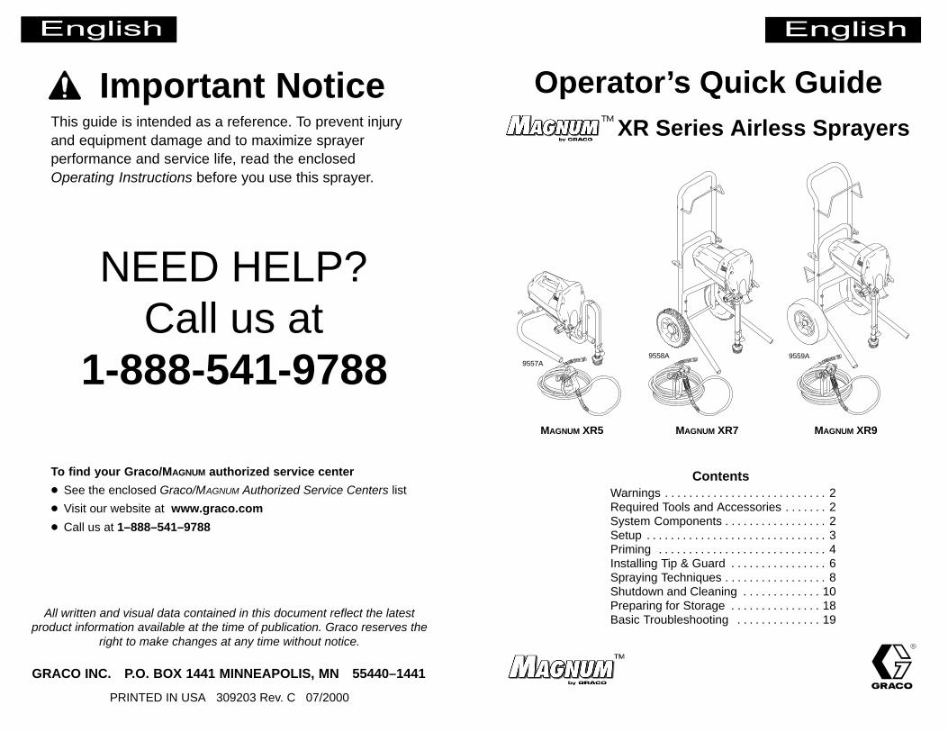
1. Screw inlet screen onto suction tube.
System is ready for next use.
Flush system (Steps 1 to 9, page 4) before spraying next coating.
inlet screen
2. Coil up hose. Leave itconnected to sprayerand gun.
Preparing for StorageStowing Sprayer
MAGNUM XR7 & XR9 have hose/cordwrap brackets on handles.
3. Wrap power cord aroundcord wrap bracket.
4. Place suctiontube and primetube in containerto catch anydrips.
Connect hose here
3
1. Unscrew tip & guard assembly fromgun to prepare for priming.
Setup
4. Turn power switch OFF.
Assembling New Sprayer or Setting Up Sprayer that Has Been Stored
3. Connect other end of hose to sprayer.
If hose isalreadyconnected,make sureconnectionsare tight.
2. Uncoil hose, andconnect one end to gun.
5. Turn Pressure Control knob all theway left (counterclockwise) tominimum pressure.
16
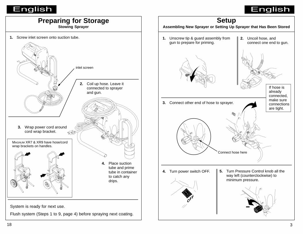
Shutdown and Cleaning
1. Place suctiontube in storagefluid bottle andprime tube inwaste pail.
PRIME
Storage fluid: Pump Armor ormineral spirits/paint thinner
Always pump storage fluid throughsystem after cleaning. Water left insprayer will corrode and ruin pump.
This is the procedure for pumpingstorage fluid through system.
WASTE
prime tube
suctiontube
Fluid InjectionHazardSee WARNINGS sheet.
Fire and ExplosionHazardSee WARNINGS sheet.
Pump Armor
Replacing Water with Storage Fluid
3. Turn Pressure Controlknob all the way left(counterclockwise) tominimum pressure.
2. TurnSpray/Primevalve toPRIME.
8. Transfer prime tube to paint pail.
5
Priming
7. � When paint starts to comeout of prime tube, pull andhold gun trigger, and turnSpray/Prime valve to SPRAY.
WASTEWASTE
PAINT
SPRAY
4. Submerge suctiontube in paint.
Fluid Splashback Hazard (see WARNINGS sheet): Keepgun trigger pulled while turning Spray/Prime valve in this step.
PAINT WASTE
Flushing Out Water and Loading Pump and Hose with Paint
pull and hold trigger
1. Turn powerswitch OFF.
5. Point gun into wastepail.
6. Turn powerswitch ON.
2. Turn gardenhose off, andunscrewPower Flushattachmentfrom suctiontube.
garden hose(turn off)
3. Screw inletscreen ontosuctiontube.
paintpaint
� When paint comes out of gun,release gun trigger.Motor stopping indicates pumpand hose are primed with paint.
14
Shutdown and Cleaning
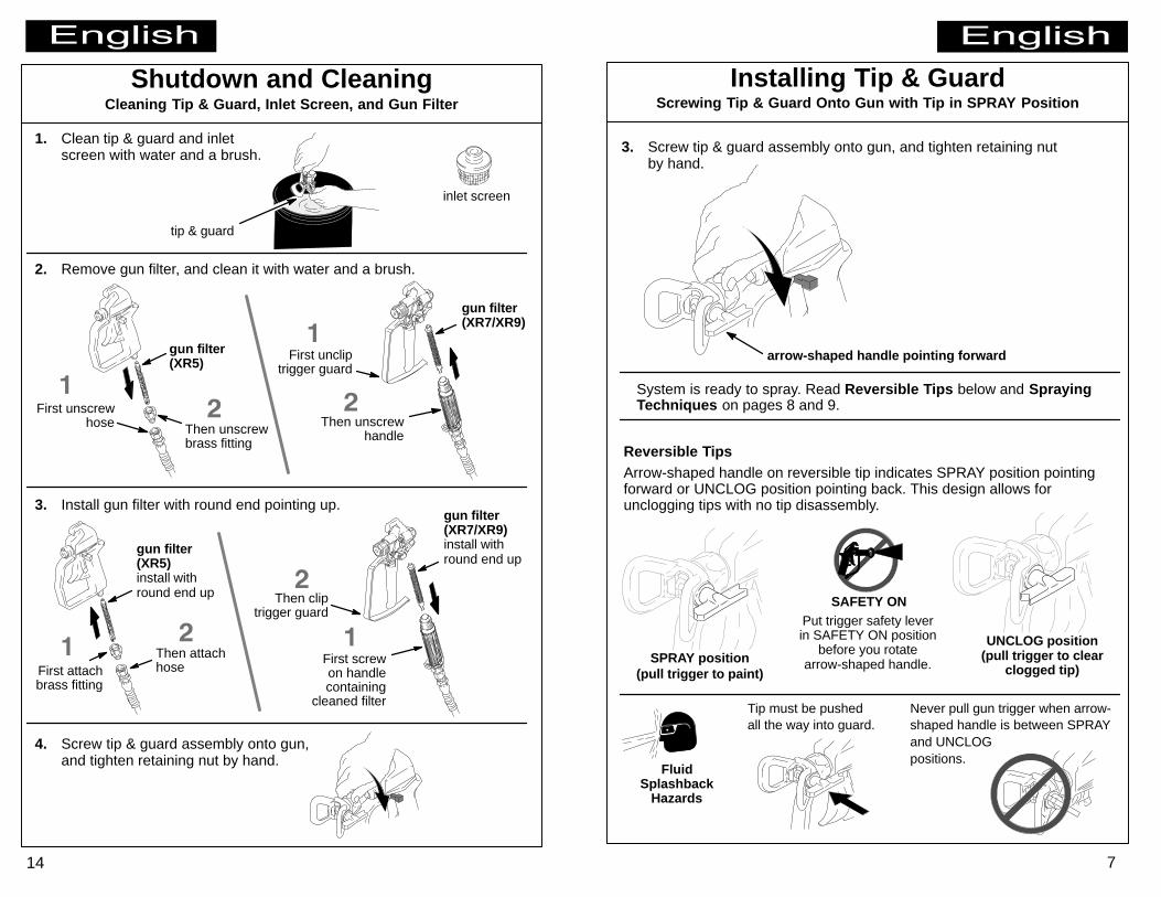
1. Clean tip & guard and inletscreen with water and a brush.
inlet screen
tip & guard
2. Remove gun filter, and clean it with water and a brush.
Cleaning Tip & Guard, Inlet Screen, and Gun Filter
gun filter(XR5)
gun filter(XR7/XR9)
First unscrewhose Then unscrew
brass fitting
First uncliptrigger guard
Then unscrewhandle
3. Install gun filter with round end pointing up.
gun filter(XR5)install withround end up
gun filter(XR7/XR9)install withround end up
First attachbrass fitting
Then attachhose
First screwon handlecontaining
cleaned filter
Then cliptrigger guard
4. Screw tip & guard assembly onto gun,and tighten retaining nut by hand.
7
Installing Tip & GuardScrewing Tip & Guard Onto Gun with Tip in SPRAY Position
System is ready to spray. Read Reversible Tips below and SprayingTechniques on pages 8 and 9.
3. Screw tip & guard assembly onto gun, and tighten retaining nutby hand.
Reversible TipsArrow-shaped handle on reversible tip indicates SPRAY position pointingforward or UNCLOG position pointing back. This design allows forunclogging tips with no tip disassembly.
UNCLOG position(pull trigger to clear
clogged tip)SPRAY position
(pull trigger to paint)
FluidSplashback
Hazards
arrow-shaped handle pointing forward
SAFETY ONPut trigger safety leverin SAFETY ON position
before you rotatearrow-shaped handle.
Tip must be pushedall the way into guard.
Never pull gun trigger when arrow-shaped handle is between SPRAYand UNCLOG positions.
12
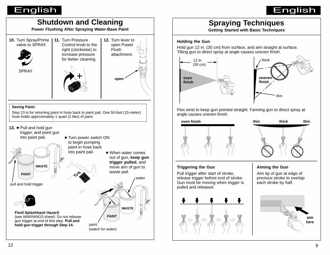
10. Turn Spray/Primevalve to SPRAY.
SPRAY
Shutdown and Cleaning
Saving Paint:
Step 13 is for returning paint in hose back to paint pail. One 50-foot (15-meter)hose holds approximately 1 quart (1 liter) of paint.
Power Flushing After Spraying Water-Base Paint
open
Fluid Splashback Hazard(see WARNINGS sheet): Do not releasegun trigger at end of this step. Pull andhold gun trigger through Step 14.
13. � Pull and hold guntrigger, and point guninto paint pail.
� When water comesout of gun, keep guntrigger pulled, andmove aim of gun towaste pail.
� Turn power switch ONto begin pumpingpaint in hose backinto paint pail.
WASTE
water
PAINT
WASTE
PAINT
paint(watch for water)
pull and hold trigger
11. Turn PressureControl knob to theright (clockwise) toincrease pressurefor better cleaning.
12. Turn lever toopen PowerFlushattachment.
9
Spraying TechniquesGetting Started with Basic Techniques
Holding the Gun
12 in.(30 cm)
evenfinish
Hold gun 12 in. (30 cm) from surface, and aim straight at surface.Tilting gun to direct spray at angle causes uneven finish.
thin
unevenfinish
thick
Flex wrist to keep gun pointed straight. Fanning gun to direct spray atangle causes uneven finish.
even finish thin thinthick
Pull trigger after start of stroke,release trigger before end of stroke.Gun must be moving when trigger ispulled and released.
Triggering the Gun
aimhere
Aim tip of gun at edge ofprevious stroke to overlapeach stroke by half.
Aiming the Gun
10
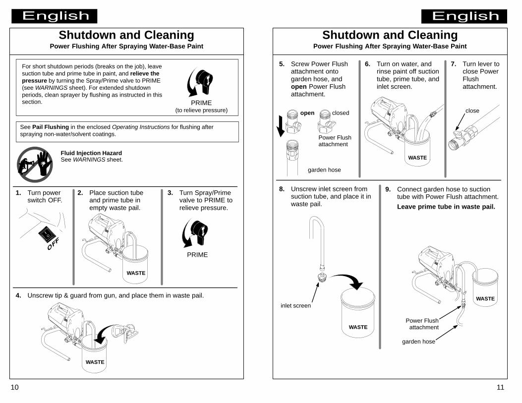
1. Turn powerswitch OFF.
Shutdown and Cleaning
For short shutdown periods (breaks on the job), leavesuction tube and prime tube in paint, and relieve thepressure by turning the Spray/Prime valve to PRIME(see WARNINGS sheet). For extended shutdownperiods, clean sprayer by flushing as instructed in thissection.
4. Unscrew tip & guard from gun, and place them in waste pail.
PRIME
WASTE
See Pail Flushing in the enclosed Operating Instructions for flushing afterspraying non-water/solvent coatings.
Fluid Injection HazardSee WARNINGS sheet.
WASTE
Power Flushing After Spraying Water-Base Paint
PRIME(to relieve pressure)
2. Place suction tubeand prime tube inempty waste pail.
3. Turn Spray/Primevalve to PRIME torelieve pressure.
11
Power Flushattachment
8. Unscrew inlet screen fromsuction tube, and place it inwaste pail.
WASTE
WASTE
Shutdown and Cleaning
WASTE
Power Flushing After Spraying Water-Base Paint
inlet screen
close
6. Turn on water, andrinse paint off suctiontube, prime tube, andinlet screen.
7. Turn lever toclose PowerFlushattachment.
5. Screw Power Flushattachment ontogarden hose, andopen Power Flushattachment.
garden hose
open closed
Power Flushattachment
9. Connect garden hose to suctiontube with Power Flush attachment.
Leave prime tube in waste pail.
garden hose
8
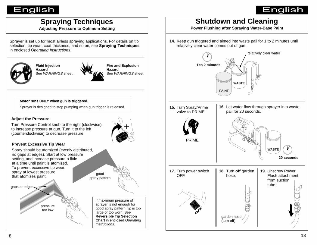
Spraying Techniques
Sprayer is set up for most airless spraying applications. For details on tipselection, tip wear, coat thickness, and so on, see Spraying Techniquesin enclosed Operating Instructions.
Motor runs ONLY when gun is triggered.
Sprayer is designed to stop pumping when gun trigger is released.
Fluid InjectionHazardSee WARNINGS sheet.
Fire and ExplosionHazardSee WARNINGS sheet.
Adjusting Pressure to Optimum Setting
Adjust the PressureTurn Pressure Control knob to the right (clockwise)to increase pressure at gun. Turn it to the left(counterclockwise) to decrease pressure.
goodspray pattern
pressuretoo low
gaps at edges
Prevent Excessive Tip WearSpray should be atomized (evenly distributed,no gaps at edges). Start at low pressuresetting, and increase pressure a littleat a time until paint is atomized.To prevent excessive tip wear,spray at lowest pressurethat atomizes paint.
If maximum pressure ofsprayer is not enough forgood spray pattern, tip is toolarge or too worn. SeeReversible Tip SelectionChart in enclosed OperatingInstructions.
1 to 2 minutes
13
Shutdown and Cleaning
15. Turn Spray/Primevalve to PRIME.
WASTE
20 seconds
PRIME
14. Keep gun triggered and aimed into waste pail for 1 to 2 minutes untilrelatively clear water comes out of gun.
Power Flushing after Spraying Water-Base Paint
17. Turn power switchOFF.
garden hose(turn off)
WASTE
relatively clear water
PAINT
16. Let water flow through sprayer into wastepail for 20 seconds.
18. Turn off gardenhose.
19. Unscrew PowerFlush attachmentfrom suctiontube.
6
Installing Tip & Guard
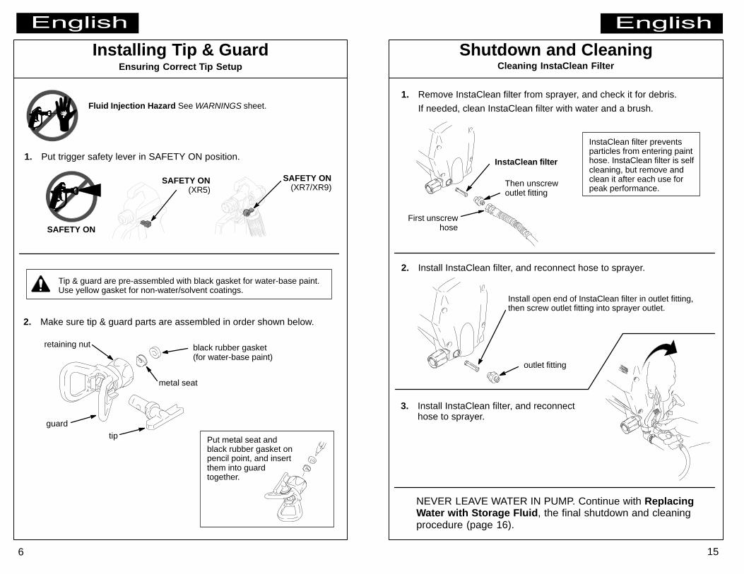
2. Make sure tip & guard parts are assembled in order shown below.
metal seat
black rubber gasket(for water-base paint)
retaining nut
Put metal seat andblack rubber gasket onpencil point, and insertthem into guardtogether.
Tip & guard are pre-assembled with black gasket for water-base paint.Use yellow gasket for non-water/solvent coatings.
guard
SAFETY ON
Ensuring Correct Tip Setup
tip
SAFETY ON(XR7/XR9)
SAFETY ON(XR5)
1. Put trigger safety lever in SAFETY ON position.
Fluid Injection Hazard See WARNINGS sheet.
15
Shutdown and Cleaning
InstaClean filter preventsparticles from entering painthose. InstaClean filter is selfcleaning, but remove andclean it after each use forpeak performance.
NEVER LEAVE WATER IN PUMP. Continue with ReplacingWater with Storage Fluid, the final shutdown and cleaningprocedure (page 16).
InstaClean filter
Then unscrewoutlet fitting
Install open end of InstaClean filter in outlet fitting,then screw outlet fitting into sprayer outlet.
1. Remove InstaClean filter from sprayer, and check it for debris.
If needed, clean InstaClean filter with water and a brush.
First unscrewhose
outlet fitting
2. Install InstaClean filter, and reconnect hose to sprayer.
Cleaning InstaClean Filter
3. Install InstaClean filter, and reconnecthose to sprayer.
Priming
WASTE
PRIME
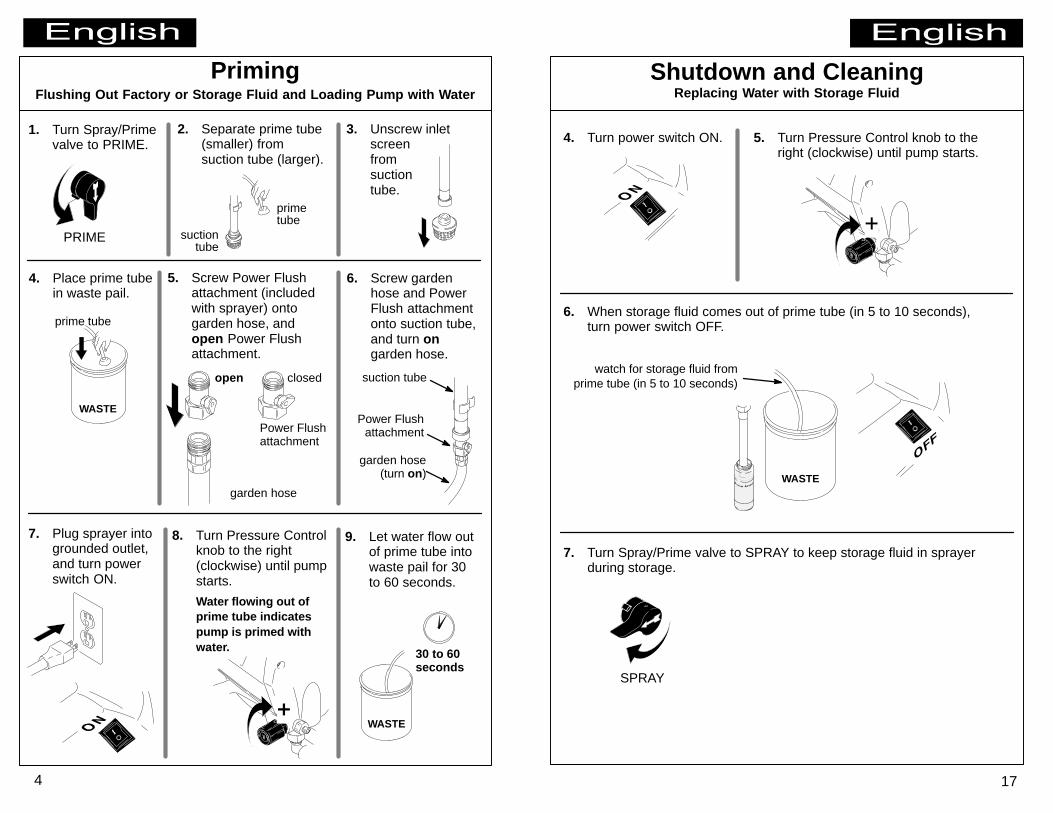
1. Turn Spray/Primevalve to PRIME.
Flushing Out Factory or Storage Fluid and Loading Pump with Water
7. Plug sprayer intogrounded outlet,and turn powerswitch ON.
5. Screw Power Flushattachment (includedwith sprayer) ontogarden hose, andopen Power Flushattachment.
prime tube
primetube
suctiontube
Power Flushattachment
suction tube
garden hose(turn on)
4
garden hose
open closed
2. Separate prime tube(smaller) fromsuction tube (larger).
4. Place prime tubein waste pail.
6. Screw gardenhose and PowerFlush attachmentonto suction tube,and turn ongarden hose.
Power Flushattachment
8. Turn Pressure Controlknob to the right(clockwise) until pumpstarts.
Water flowing out ofprime tube indicatespump is primed withwater.
3. Unscrew inletscreenfromsuctiontube.
30 to 60seconds
9. Let water flow outof prime tube intowaste pail for 30to 60 seconds.
WASTE
17
6. When storage fluid comes out of prime tube (in 5 to 10 seconds),turn power switch OFF.
watch for storage fluid fromprime tube (in 5 to 10 seconds)
7. Turn Spray/Prime valve to SPRAY to keep storage fluid in sprayerduring storage.
SPRAY
WASTE
4. Turn power switch ON.
Shutdown and CleaningReplacing Water with Storage Fluid
5. Turn Pressure Control knob to theright (clockwise) until pump starts.
PressureControlknob
2
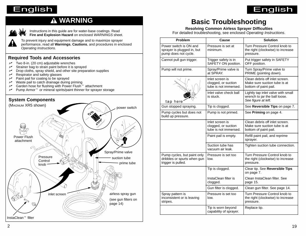
WARNINGInstructions in this guide are for water-base coatings. ReadFire and Explosion Hazard on enclosed WARNINGS sheet.
To prevent injury and equipment damage and to maximize sprayerperformance, read all Warnings, Cautions, and procedures in enclosedOperating Instructions.
Required Tools and Accessories� Two 8-in. (20 cm) adjustable wrenches� Strainer bag to strain paint before it is sprayed� Drop cloths, spray shield, and other site preparation supplies� Respirator and safety glasses� Paint pail for coating to be sprayed� Waste pail to catch drainage during priming� Garden hose for flushing with Power Flush� attachment� Pump Armor� or mineral spirits/paint thinner for sprayer storage
(MAGNUM XR5 shown)
suction tube
prime tube
inlet screen
power switch
Power Flushattachment
InstaClean� filter
airless spray gun
(see gun filters onpage 14)
System Components
Spray/Prime valve
Basic TroubleshootingResolving Common Airless Sprayer Difficulties
For detailed troubleshooting, see enclosed Operating Instructions.
Problem Cause Solution
Power switch is ON andsprayer is plugged in, butpump does not cycle.
Pressure is set atminimum.
Turn Pressure Control knob tothe right (clockwise) to increasepressure.
Cannot pull gun trigger. Trigger safety is inSAFETY ON position.
Put trigger safety in SAFETYOFF position.
Pump will not prime. Spray/Prime valve isat SPRAY.
Turn Spray/Prime valve toPRIME (pointing down).
Inlet screen isclogged, or suctiontube is not immersed.
Clean debris off inlet screen.Make sure suction tube is atbottom of paint pail.
Inlet valve check ballis stuck.
Lightly tap inlet valve with smallwrench to jar the ball loose.See figure at left.
Gun stopped spraying. Tip is clogged. See Reversible Tips on page 7.
Pump cycles but does notbuild up pressure.
Pump is not primed. See Priming on page 4.
Inlet screen isclogged, or suctiontube is not immersed.
Clean debris off inlet screen.Make sure suction tube is atbottom of paint pail.
Paint pail is empty. Refill paint pail, and reprimesprayer.
Suction tube hasvacuum air leak.
Tighten suction tube connection.
Pump cycles, but paint onlydribbles or spurts when guntrigger is pulled.
Pressure is set toolow.
Turn Pressure Control knob tothe right (clockwise) to increasepressure.
Tip is clogged. Clear tip. See Reversible Tipson page 7.
InstaClean filter isclogged.
Clean InstaClean filter. Seepage 15.
Gun filter is clogged. Clean gun filter. See page 14.
Spray pattern isinconsistent or is leavingstripes.
Pressure is set toolow.
Turn Pressure Control knob tothe right (clockwise) to increasepressure.
Tip is worn beyondcapability of sprayer.
Replace tip.
19