Embed Size (px)
Citation preview

30XW-VVariable-speed water-cooledscrew chiller & heat pump

Founded by the inventor of modern air conditioning, Carrier is the world’s
leader in high-technology heating, air-conditioning and refrigeration solutions.
Carrier experts provide sustainable solutions, integrating energy-efficient
products, building controls and energy services for residential, commercial,
retail, transport and food service customers. Carrier is a part of UTC Build
ing & Industrial Systems, a unit of United Technologies Corp., a leading
provider to the aerospace and building systems industries worldwide.
With a broad portfolio of advanced technical patent awards, our global R&D
center in Shanghai develops innovative heat, ventilation and air-conditioning
(HVAC) solutions.
Turn To The Experts
In 1998, Time magazine named Dr. Carrier oneof its 20 most influential builders and titans ofthe 20thcentury.
2
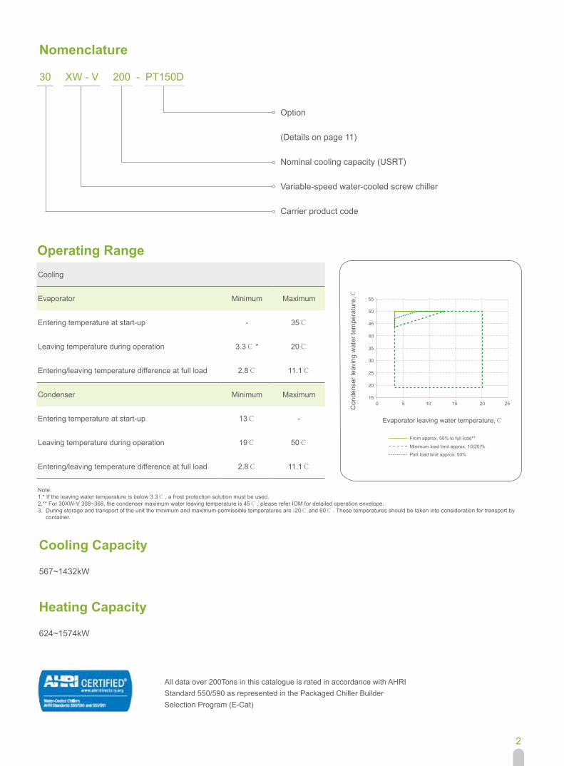
Nomenclature
Option
(Details on page 11)
Nominal cooling capacity (USRT)
Variable-speed water-cooled screw chiller
Carrier product code
30 XW - V 200 - PT150D
Operating RangeCooling
Evaporator Minimum Maximum
Entering temperature at start-up - 35℃
Leaving temperature during operation 3.3℃ * 20℃
Entering/leaving temperature difference at full load 2.8℃ 11.1℃
Condenser Minimum Maximum
Entering temperature at start-up 13℃ -
Leaving temperature during operation 19℃ 50℃
Entering/leaving temperature difference at full load 2.8℃ 11.1℃
Note: 1.* If the leaving water temperature is below 3.3℃ , a frost protection solution must be used. 2.** For 30XW-V 308~368, the condenser maximum water leaving temperature is 45℃ , please refer IOM for detailed operation envelope.3. During storage and transport of the unit the minimum and maximum permissible temperatures are -20℃ and 60℃ . These temperatures should be taken into consideration for transport by container.
55
50
45
40
35
30
25
20
150 5 10 15 20 25
Evaporator leaving water temperature,℃
Con
dens
er le
avin
g w
ater
tem
pera
ture
, ℃
From approx. 50% to full load**
Minimum load limit approx. 10(20)%
Part load limit approx. 50%
Cooling Capacity
Heating Capacity
567~1432kW
624~1574kW
All data over 200Tons in this catalogue is rated in accordance with AHRIStandard 550/590 as represented in the Packaged Chiller BuilderSelection Program (E-Cat)

3
The air conditioning system uses about 40% of the annual building energy consumption. Selection of the right air conditioning unit is one the main aspects to consider when designing a green building.Buildings with a variable load throughout the year 30XW-V units offer the solution to this important challenge. High efficiency inverter with automatic energy optimization function, optimise energy savings due to quicker commissioning and better system efficiency. The low total harmonic current distortion rate (THDI) options ensure that the VFD can not ex-ceed IEEE-519 standard, for distortion at the points of commom coupling, the evaluation of the compatibility level of harmonic interference on the public low-voltage power distribution system can be done using technical report IEC61000-3-4. With the primary pump variable flow system, variable speed chiller and water pump unit synchronous control, to meet the energy saving demands.
General Features
High Energy Efficiency
Variable-frequency for green building design
The AquaForce 30XW-V variable speed screw chillers are the premium solution for industrial and commercial applications where installers, consultants and building owners require maximum quality and optimal performances, especially at part load.They are designed to meet current and future requirements in terms of energy efficiency, versatility and compactness. The 30XW-V use the most reliable technologies available today:· Exclusive inverter-driven screw compressors, an evolution of the proven traditional Carrier twin-rotor screw compressor design.· New Touch Pilot control.· Extremely efficient mechanically cleanable flooded evaporators.· Environment stewardship refrigerant HFC-134a.The 30XW-V range is split into two versions:· 30XW-V for air conditioning and refrigeration applications.· 30XW-V-PT150D/G for hot water and heating applications.As standard, the unit can provide an evaporator leaving water temperature down to 3.3℃ , and when operating as a heat pump, it can deliver up to 50℃ on the condenser side.
The 30XW-V was designed for high performance both at full load and at part load. Exceptional IPLV/NPLV* values set new benchmarks for low energy consumption.Inverter-driven twin-rotor screw compressors allow precise capacity matching of building load changes and significantly reduce unit power input, especially at part-load.Flooded multi-pipe evaporator and condenser for increased heat exchange efficiency.Electronic expansion device permits operation at a lower condensing pressure and improved utilization of the evaporator heat exchange surface.Inverter-driven motors ensure negligible start-up current, optimised electrical performance.
100% 75% 50% 25%Load
Traditional fixed-speed screw chiller30XWV
IPLV=7.4
IPLV=9.7
IPLV +30%
Part Load Efficiency(AHRI)
CO
P(k
W/k
W)
14.0
11.0
8.0
5.0
2.0
Time(s)
Cur
rent
dra
w (A
)
Low Start-up Current
Notes: *IPLV(Integrated Part-Load Value), a single number of part-load efficiency, it’s rated at 100%, 75%, 50%, and 25% load relative to the full-load rating net refrigerating capacity at the standard rating AHRI conditions. Condenser EWT is 29.4℃ ,23.8℃ ,18.3℃ ,18.3℃ , respectively. Evaporator LWT is kept constant 6.7℃ .NPLV(Non-Standard Part-Load Value), a single number of part-load efficiency referenced to conditions other than IPLV conditions. At 100% load, the condenser EWT is user-defined, at 75% load, condenser EWT is vary linearly from the selected EWT at 100% load to 18.3℃ at 50% load, and fixed at 18.3℃ for 50% to 0% load. Evaporator LWT at each load is user-defined too.
4
Stewardship refrigerant
· HFC-134a refrigerant with zero ozone depletion potential, has no expire date.
Leak-tight refrigerant circuit
· Reduction of leaks as no capillary tubes and flare connections are used.
· Verification of pressure transducers and temperature sensors without transferring refrigerant
charge.
· Discharge line shut-off valve and liquid line service valve for simplified maintenance.
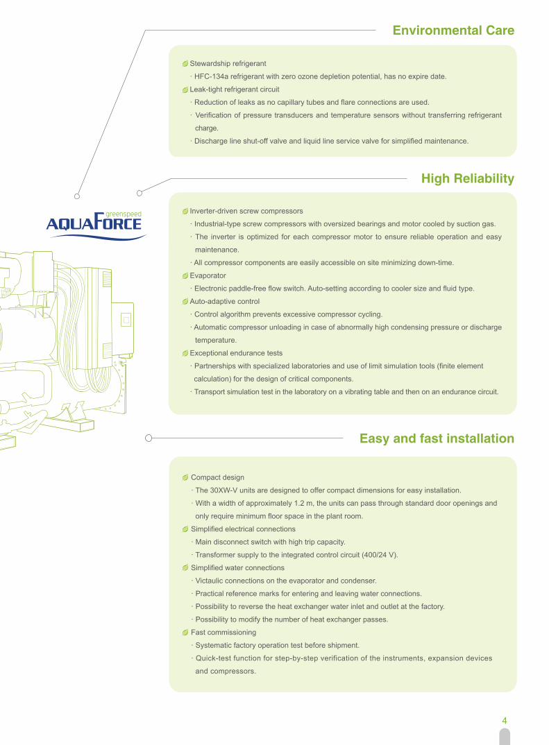
Inverter-driven screw compressors
· Industrial-type screw compressors with oversized bearings and motor cooled by suction gas.
· The inverter is optimized for each compressor motor to ensure reliable operation and easy
maintenance.
· All compressor components are easily accessible on site minimizing down-time.
Evaporator
· Electronic paddle-free flow switch. Auto-setting according to cooler size and fluid type.
Auto-adaptive control
· Control algorithm prevents excessive compressor cycling.
· Automatic compressor unloading in case of abnormally high condensing pressure or discharge
temperature.
Exceptional endurance tests
· Partnerships with specialized laboratories and use of limit simulation tools (finite element
calculation) for the design of critical components.
· Transport simulation test in the laboratory on a vibrating table and then on an endurance circuit.
Compact design
· The 30XW-V units are designed to offer compact dimensions for easy installation.
· With a width of approximately 1.2 m, the units can pass through standard door openings and
only require minimum floor space in the plant room.
Simplified electrical connections
· Main disconnect switch with high trip capacity.
· Transformer supply to the integrated control circuit (400/24 V).
Simplified water connections
· Victaulic connections on the evaporator and condenser.
· Practical reference marks for entering and leaving water connections.
· Possibility to reverse the heat exchanger water inlet and outlet at the factory.
· Possibility to modify the number of heat exchanger passes.
Fast commissioning
· Systematic factory operation test before shipment.
· Quick-test function for step-by-step verification of the instruments, expansion devices
and compressors.
Environmental Care
High Reliability
Easy and fast installation
5
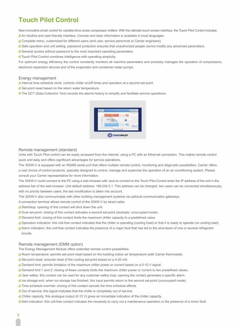
Touch Pilot ControlNew innovative smart control for variable-drive screw compressor chillers. With the ultimate touch screen interface, the Touch Pilot Control includes:-- An intuitive and user-friendly interface. Concise and clear information is available in local languages.-- Complete menu, customized for different users (end user, service personnel or Carrier engineers).-- Safe operation and unit setting: password protection ensures that unauthorized people cannot modify any advanced parameters.-- General access without password to the most important operating parameters.-- Touch Pilot Control combines intelligence with operating simplicity.For optimum energy efficiency the control constantly monitors all machine parameters and precisely manages the operation of compressors, electronic expansion devices and of the evaporator and condenser water pumps.
Energy management-- Internal time schedule clock: controls chiller on/off times and operation at a second set-point. -- Set-point reset based on the return water temperature. -- The DCT (Data Collection Tool) records the alarms history to simplify and facilitate service operations.
Remote management (standard)Units with Touch Pilot control can be easily accessed from the internet, using a PC with an Ethernet connection. This makes remote controlquick and easy and offers significant advantages for service operations.The 30XW-V is equipped with an RS485 serial port that offers multiple remote control, monitoring and diagnostic possibilities. Carrier offersa vast choice of control products, specially designed to control, manage and supervise the operation of an air conditioning system. Pleaseconsult your Carrier representative for more information.The 30XW-V could connect to the PC using a web browser with Java to connect to the Touch Pilot Control enter the IP address of the unit in theaddress bar of the web browser. Unit default address: 169.254.0.1. This address can be changed, two users can be connected simultaneously,with no priority between users; the last modification is taken into account.The 30XW-V also communicates with other building management systems via optional communication gateways.A connection terminal allows remote control of the 30XW-V by wired cable:-- Start/stop: opening of this contact will shut down the unit.-- Dual set-point: closing of this contact activates a second set-point (example: unoccupied mode).-- Demand limit: closing of this contact limits the maximum chiller capacity to a predefined value.-- Operation indication: this volt-free contact indicates that the chiller is operating (cooling load) or that it is ready to operate (no cooling load).-- Alarm indication: this volt-free contact indicates the presence of a major fault that has led to the shut-down of one or several refrigerant circuits.
Remote management (EMM option)The Energy Management Module offers extended remote control possibilities:-- Room temperature: permits set-point reset based on the building indoor air temperature (with Carrier thermostat).-- Set point reset: ensures reset of the cooling set-point based on a 4-20 mA.-- Demand limit: permits limitation of the maximum chiller power or current based on a 0-10 V signal.-- Demand limit 1 and 2: closing of these contacts limits the maximum chiller power or current to two predefined values.-- User safety: this contact can be used for any customer safety loop; opening the contact generates a specific alarm.-- Ice storage end: when ice storage has finished, this input permits return to the second set-point (unoccupied mode).-- Time schedule override: closing of this contact cancels the time schedule effects.-- Out of service: this signal indicates that the chiller is completely out of service.-- Chiller capacity: this analogue output (0-10 V) gives an immediate indication of the chiller capacity.-- Alert indication: this volt-free contact indicates the necessity to carry out a maintenance operation or the presence of a minor fault.
6
Carrier products and green building certification
IntroductionEnergy usage and costs combined with increasing concerns to reduce CO2 emissions are among the most important environmental challenges in today’s world. New and existing buildings are one area where energy efficiency and the conservation of natural resources is a high priority.
Green building designDesign teams increasingly focus on designing “green buildings” to address today's energy efficiency and environmental sustainability needs. A green building is a building that is environmentally sustainable and has been designed, constructed and is operated to minimise the total impact of the environment.
The underlying principles of this approach: the resulting building will be economical to operate, offer increased comfort and create a healthier environment for the people who live and work there, increasing productivity.
The main strategies* adopted to achieve a green building design include:-- Sustainable Sites (SS)-- Water Efficiency (WE)-- Energy & Atmosphere (EA)-- Materials & Resources (MR)-- Indoor Environmental Quality (IEQ)-- Innovation in Design (ID)
Green building certificationA number of green building certification programs exist in the market and offer third-party assessment of green building measures for a wide variety of building types. Some examples of existing programs include:-- LEED (Leadership in Energy & Environmental Design)-- BREEAM-- ESTIDAMA PEARL-- NABERS (National Australian Built Environment Rating System)
HVAC products and systemsCarrier HVAC products are built to high energy efficiency and indoor air quality standards. They assist building designers and owners by offering high-performance heating, ventilation, and air conditioning (HVAC) systems and products with reduced energy consumption and enhanced indoor air quality for the occupants, contributing to optimised green building performance.
Each certification program may address and prioritise different green building design strategies according to local and regional needs and legislation. The following example looks at how Carrier's new 30XW-V range helps customers involved in LEED building certification.* Source USGBC: LEED
Example: 30XW-V and LEED® certificationThe LEED® (Leadership in Energy and Environmental Design) green building certification programme is a pre-eminent programme to rate the design, construction and operation of green buildings with points assigned in seven credit categories:-- Sustainable Sites (SS)-- Water Efficiency (WE)-- Energy & Atmosphere (EA)-- Materials & Resources (MR)-- Indoor Environmental Quality (IEQ)-- Innovation in Design (ID)-- Regional Priority (RP)
There are a number of different LEED® products. Whilst the strategies and categories assessed remain the same, the point distribution varies to address different building types and application needs, for example according to New Construction, Schools, Core & Shell, Retail and Healthcare. All programmes now use the same point scale.
The majority of credits in LEED® rating systems are performance-based and achieving them is dependent on the impacts to the overall building.
The contribution any product or system may make to the points achieved depends on how it impacts the entire building and its operations.
7
Whilst the LEED® green building certification programme does not certify products or services, the selection of products or service programmes is critical to obtaining LEED® certification for a registered project because the right products or service programmes can help meet the goals of green construction and ongoing operation and maintenance.
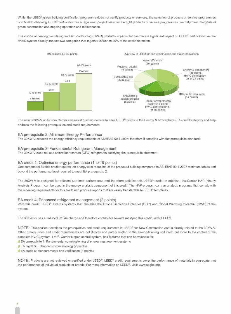
The choice of heating, ventilating and air conditioning (HVAC) products in particular can have a significant impact on LEED® certification, as the HVAC system directly impacts two categories that together influence 40% of the available points.
The new 30XW-V units from Carrier can assist building owners to earn LEED® points in the Energy & Atmosphere (EA) credit category and help address the following prerequisites and credit requirements:
EA prerequisite 2: Minimum Energy PerformanceThe 30XW-V exceeds the energy-efficiency requirements of ASHRAE 90.1-2007; therefore it complies with the prerequisite standard.
EA prerequisite 3: Fundamental Refrigerant ManagementThe 30XW-V does not use chlorofluorocarbon (CFC) refrigerants satisfying the prerequisite statement
EA credit 1; Optimise energy performance (1 to 19 points)One component for this credit requires the energy cost reduction of the proposed building compared to ASHRAE 90.1-2007 minimum tables and beyond the performance level required to meet EA prerequisite 2.
The 30XW-V is designed for efficient part-load performance and therefore satisfies this LEED® credit. In addition, the Carrier HAP (Hourly Analysis Program) can be used in the energy analysis component of this credit. The HAP program can run analysis programs that comply with the modeling requirements for this credit and produce reports that are easily transferable to LEED® templates.
EA credit 4: Enhanced refrigerant management (2 points)With this credit, LEED® awards systems that minimise the Ozone Depletion Potential (ODP) and Global Warming Potential (GWP) of the system.
The 30XW-V uses a reduced R134a charge and therefore contributes toward satisfying this credit under LEED®.
NOTE: This section describes the prerequisites and credit requirements in LEED® for New Construction and is directly related to the 30XW-V. Other prerequisites and credit requirements are not directly and purely related to the air-conditioning unit itself, but more to the control of the complete HVAC system. i-Vu®, Carrier’s open control system, has features that can be valuable for:-- EA prerequisite 1: Fundamental commissioning of energy management systems-- EA credit 3: Enhanced commissioning (2 points)-- EA credit 5: Measurements and verification (3 points)
NOTE: Products are not reviewed or certified under LEED®. LEED® credit requirements cover the performance of materials in aggregate, not the performance of individual products or brands. For more information on LEED®, visit: www.usgbc.org.
50-59 points
Silver40-49 points
60-79 points
Gold
80-100 points
Platinum
110 possible LEED points Overview of LEED for new construction and major renovations
Regional priority (4 points)
Sustainable site (25 points)
Innovation & design process
(6 points)
Material & Resources (14 points)
Indoor environmental quality (15 points)
HVAC contribution 6 of 15 points
Energy & atmosphere (35 points)
HVAC contribution 26 of 35 points
Water efficiency(10 points)
8
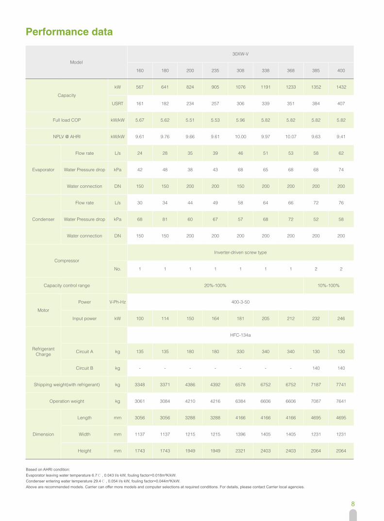
Performance data
Based on AHRI condition: Evaporator leaving water temperature 6.7℃ , 0.043 l/s·kW, fouling factor=0.018m²K/kW. Condenser entering water temperature 29.4℃ , 0.054 l/s·kW, fouling factor=0.044m²K/kW.Above are recommended models. Carrier can offer more models and computer selections at required conditions. For details, please contact Carrier local agencies.
Model
30XW-V
160 180 200 235 308 338 368 385 400
Capacity
kW 567 641 824 905 1076 1191 1233 1352 1432
USRT 161 182 234 257 306 339 351 384 407
Full load COP kW/kW 5.67 5.62 5.51 5.53 5.96 5.82 5.82 5.82 5.82
NPLV @ AHRI kW/kW 9.61 9.76 9.66 9.61 10.00 9.97 10.07 9.63 9.41
Evaporator
Flow rate L/s 24 28 35 39 46 51 53 58 62
Water Pressure drop kPa 42 48 38 43 68 65 68 68 74
Water connection DN 150 150 200 200 150 200 200 200 200
Condenser
Flow rate L/s 30 34 44 49 58 64 66 72 76
Water Pressure drop kPa 68 81 60 67 57 68 72 52 58
Water connection DN 150 150 200 200 200 200 200 200 200
Compressor
Inverter-driven screw type
No. 1 1 1 1 1 1 1 2 2
Capacity control range 20%-100% 10%-100%
Motor
Power V-Ph-Hz 400-3-50
Input power kW 100 114 150 164 181 205 212 232 246
Refrigerant Charge
HFC-134a
Circuit A kg 135 135 180 180 330 340 340 130 130
Circuit B kg - - - - - - - 140 140
Shipping weight(with refrigerant) kg 3348 3371 4386 4392 6578 6752 6752 7187 7741
Operation weight kg 3061 3084 4210 4216 6384 6606 6606 7087 7641
Dimension
Length mm 3056 3056 3288 3288 4166 4166 4166 4695 4695
Width mm 1137 1137 1215 1215 1396 1405 1405 1231 1231
Height mm 1743 1743 1949 1949 2321 2403 2403 2064 2064

9
Performance data, 30XW-V Heating units (Option)
Cooling condition: Evaporator entering/leaving water temperature 12℃ /7℃ . Condenser entering/leaving water temperature 30℃ /35℃ . Heating conditions: Evaporator entering/leaving water temperature 15℃ /7℃ . Condenser entering/leaving water temperature 40℃ /45℃ . Evaporator fouling factor=0.018m²K/kW, Condenser fouling factor=0.044m²K/kW. Cooling and heating capacity based on maximum load(60Hz).Maximun heating temperature 50℃ . 30XW308/338/368 maximum temperature is 45℃ .Above are recommended models. Carrier can offer more models and computer selections at required conditions. For details, please contact Carrier local agencies.
Model30XW-V-PT150D/G
160 180 200 235 308 338 368 385 400
Cooling
Cooling Capacity kW 569 644 828 910 1081 1196 1239 1360 1436
Input power kW 101 115 151 165 183 207 214 235 248
EvaporatorFlow rate L/s 27 31 40 43 52 57 59 65 68
Water Pressure drop kPa 50 57 49 55 85 80 85 82 90
CondenserFlow rate L/s 32 36 47 51 60 67 69 76 80
Water Pressure drop kPa 75 90 66 73 61 74 78 57 63
Heating
Heating Capacity kW 624 706 905 1001 1193 1324 1371 1491 1575
Input power kW 133 148 189 213 239 270 279 300 323
EvaporatorFlow rate L/s 15 17 22 24 29 32 33 36 38
Water Pressure drop kPa 19 22 15 15 27 25 26 28 31
CondenserFlow rate L/s 30 34 44 48 58 64 66 72 76
Water Pressure drop kPa 64 77 55 63 53 65 68 50 55
Condenser water connection DN 150 150 200 200 150 200 200 200 200
Evaporator water connection DN 150 150 200 200 200 200 200 200 200
CompressorInverter-driven screw type
No. 1 1 1 1 1 1 1 2 2
Capacity control range 20%-100% 10%-100%
Power V-Ph-Hz 400-3-50
Refrigerant Charge
HFC-134a
Circuit A kg 135 135 180 180 330 340 340 130 130
Circuit B kg - - - - - - - 140 140
Shipping weight(with refrigerant) kg 3348 3371 4386 4392 6578 6752 6752 7187 7741
Operation weight kg 3061 3084 4210 4216 6384 6606 6606 7087 7641
Dimension
Length mm 3056 3056 3288 3288 4166 4166 4166 4695 4695
Width mm 1137 1137 1215 1215 1396 1405 1405 1231 1231
Height mm 1743 1743 1949 1949 2321 2403 2403 2064 2064
10
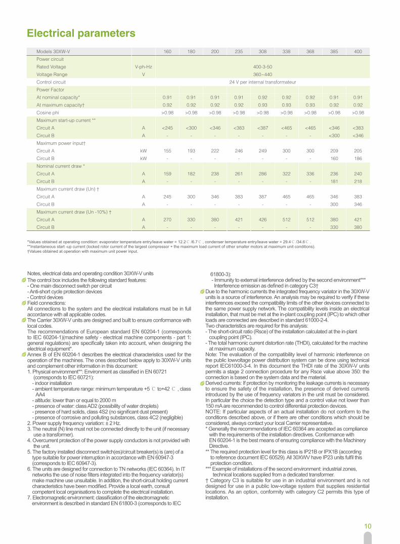
Performance data, 30XW-V Heating units (Option) Electrical parameters
*Values obtained at operating condition: evaporator temperature entry/leave water = 12.2℃ /6.7℃ , condenser temperature entry/leave water = 29.4℃ /34.6℃ . **Instantaneous start -up current (locked rotor current of the largest compressor + the maximum load current of other smaller motors at maximum unit conditions). †Values obtained at operation with maximum unit power input.
Models 30XW-V 160 180 200 235 308 338 368 385 400
Power circuit
Rated Voltage V-ph-Hz 400-3-50
Voltage Range V 360~440
Control circuit 24 V per internal transformateur
Power Factor
At nominal capacity* 0.91 0.91 0.91 0.91 0.92 0.92 0.92 0.91 0.91
At maximum capacity† 0.92 0.92 0.92 0.92 0.93 0.93 0.93 0.92 0.92
Cosine phi >0.98 >0.98 >0.98 >0.98 >0.98 >0.98 >0.98 >0.98 >0.98
Maximum start-up current **
Circuit A A <245 <300 <346 <383 <387 <465 <465 <346 <383
Circuit B A - - - - - - - <300 <346
Maximum power input†
Circuit A kW 155 193 222 246 249 300 300 209 205
Circuit B kW - - - - - - - 160 186
Nominal current draw *
Circuit A A 159 182 238 261 286 322 336 236 240
Circuit B A - - - - - - - 181 218
Maximum current draw (Un) †
Circuit A A 245 300 346 383 387 465 465 346 383
Circuit B A - - - - - - - 300 346
Maximum current draw (Un -10%) †
Circuit A A 270 330 380 421 426 512 512 380 421
Circuit B A - - - - - - - 330 380
The control box includes the following standard features:- One main disconnect switch per circuit- Anti-short cycle protection devices- Control devicesField connections:All connections to the system and the electrical installations must be in full accordance with all applicable codes.The Carrier 30XW-V units are designed and built to ensure conformance with local codes.The recommendations of European standard EN 60204-1 (corresponds to IEC 60204-1)(machine safety - electrical machine components - part 1: general regulations) are specifically taken into account, when designing the electrical equipment*.Annex B of EN 60204-1 describes the electrical characteristics used for the operation of the machines. The ones described below apply to 30XW-V units and complement other information in this document:1. Physical environment**: Environment as classified in EN 60721 (corresponds to IEC 60721): - indoor installation - ambient temperature range: minimum temperature +5 ℃ to+42 ℃ , class AA4 - altitude: lower than or equal to 2000 m - presence of water: class AD2 (possibility of water droplets) - presence of hard solids, class 4S2 (no significant dust present) - presence of corrosive and polluting substances, class 4C2 (negligible)2. Power supply frequency variation: ± 2 Hz.3. The neutral (N) line must not be connected directly to the unit (if necessary use a transformer).4. Overcurrent protection of the power supply conductors is not provided with the unit.5. The factory installed disconnect switch(es)/circuit breaker(s) is (are) of a type suitable for power interruption in accordance with EN 60947-3 (corresponds to IEC 60947-3).6. The units are designed for connection to TN networks (IEC 60364). In IT networks the use of noise filters integrated into the frequency variator(s) make machine use unsuitable. In addition, the short-circuit holding current characteristics have been modified. Provide a local earth, consult competent local organisations to complete the electrical installation.7. Electromagnetic environment: classification of the electromagnetic environment is described in standard EN 61800-3 (corresponds to IEC
61800-3): - Immunity to external interference defined by the second environment*** Interference emission as defined in category C3†Due to the harmonic currents the integrated frequency variator in the 30XW-V units is a source of interference. An analysis may be required to verify if these interferences exceed the compatibility limits of the other devices connected to the same power supply network. The compatibility levels inside an electrical installation, that must be met at the in-plant coupling point (IPC) to which other loads are connected are described in standard 61000-2-4.Two characteristics are required for this analysis:- The short-circuit ratio (Rsce) of the installation calculated at the in-plant coupling point (IPC).- The total harmonic current distortion rate (THDI), calculated for the machine at maximum capacity.Note: The evaluation of the compatibility level of harmonic interference on the public lowvoltage power distribution system can be done using technical report IEC61000-3-4. In this document the THDI rate of the 30XW-V units permits a stage 2 connection procedure for any Rsce value above 350: the connection is based on the system data and the material.Derived currents: If protection by monitoring the leakage currents is necessary to ensure the safety of the installation, the presence of derived currents introduced by the use of frequency variators in the unit must be considered. In particular the choice the detection type and a control value not lower than 150 mA are recommended to control differential protection devices.NOTE: If particular aspects of an actual installation do not conform to the conditions described above, or if there are other conditions which should be considered, always contact your local Carrier representative.* Generally the recommendations of IEC 60364 are accepted as compliance with the requirements of the installation directives. Conformance with EN 60204-1 is the best means of ensuring compliance with the Machinery Directive.** The required protection level for this class is IP21B or IPX1B (according to reference document IEC 60529). All 30XWV have IP23 units fulfil this protection condition.*** Example of installations of the second environment: industrial zones, technical locations supplied from a dedicated transformer.† Category C3 is suitable for use in an industrial environment and is not designed for use in a public low-voltage system that supplies residential locations. As an option, conformity with category C2 permits this type of installation.
Notes, electrical data and operating condition 30XW-V units
11
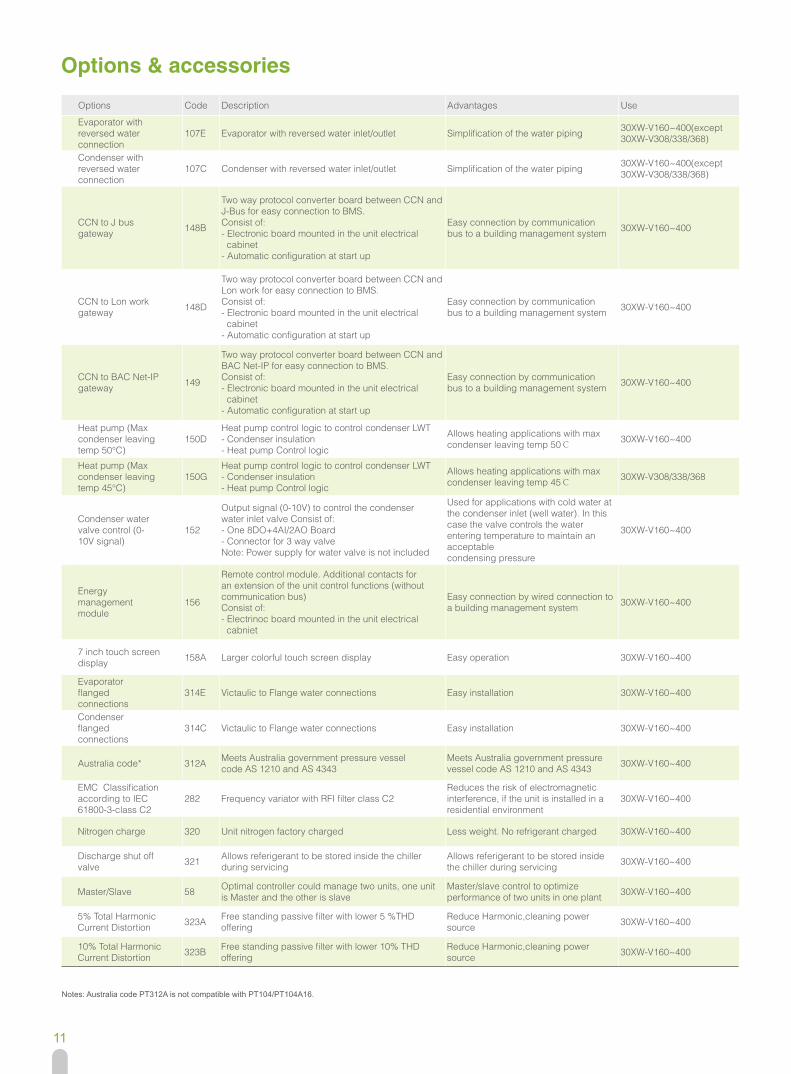
Options & accessories
Notes: Australia code PT312A is not compatible with PT104/PT104A16.
Options Code Description Advantages Use
Evaporator with reversed water connection
107E Evaporator with reversed water inlet/outlet Simplification of the water piping 30XW-V160~400(except 30XW-V308/338/368)
Condenser with reversed water connection
107C Condenser with reversed water inlet/outlet Simplification of the water piping 30XW-V160~400(except 30XW-V308/338/368)
CCN to J bus gateway 148B
Two way protocol converter board between CCN and J-Bus for easy connection to BMS. Consist of: - Electronic board mounted in the unit electrical cabinet - Automatic configuration at start up
Easy connection by communication bus to a building management system 30XW-V160~400
CCN to Lon work gateway 148D
Two way protocol converter board between CCN and Lon work for easy connection to BMS. Consist of: - Electronic board mounted in the unit electrical cabinet - Automatic configuration at start up
Easy connection by communication bus to a building management system 30XW-V160~400
CCN to BAC Net-IP gateway 149
Two way protocol converter board between CCN and BAC Net-IP for easy connection to BMS. Consist of: - Electronic board mounted in the unit electrical cabinet - Automatic configuration at start up
Easy connection by communication bus to a building management system 30XW-V160~400
Heat pump (Max condenser leaving temp 50°C)
150DHeat pump control logic to control condenser LWT - Condenser insulation - Heat pump Control logic
Allows heating applications with max condenser leaving temp 50℃
30XW-V160~400
Heat pump (Max condenser leaving temp 45°C)
150GHeat pump control logic to control condenser LWT - Condenser insulation - Heat pump Control logic
Allows heating applications with max condenser leaving temp 45℃
30XW-V308/338/368
Condenser water valve control (0- 10V signal)
152
Output signal (0-10V) to control the condenser water inlet valve Consist of: - One 8DO+4AI/2AO Board - Connector for 3 way valve Note: Power supply for water valve is not included
Used for applications with cold water at the condenser inlet (well water). In this case the valve controls the water entering temperature to maintain an acceptable condensing pressure
30XW-V160~400
Energy management module
156
Remote control module. Additional contacts for an extension of the unit control functions (without communication bus) Consist of: - Electrinoc board mounted in the unit electrical cabniet
Easy connection by wired connection to a building management system 30XW-V160~400
7 inch touch screen display 158A Larger colorful touch screen display Easy operation 30XW-V160~400
Evaporator flanged connections
314E Victaulic to Flange water connections Easy installation 30XW-V160~400
Condenser flanged connections
314C Victaulic to Flange water connections Easy installation 30XW-V160~400
Australia code* 312A Meets Australia government pressure vessel code AS 1210 and AS 4343
Meets Australia government pressure vessel code AS 1210 and AS 4343 30XW-V160~400
EMC Classification according to IEC 61800-3-class C2
282 Frequency variator with RFI filter class C2Reduces the risk of electromagnetic interference, if the unit is installed in a residential environment
30XW-V160~400
Nitrogen charge 320 Unit nitrogen factory charged Less weight. No refrigerant charged 30XW-V160~400
Discharge shut off valve 321 Allows referigerant to be stored inside the chiller
during servicingAllows referigerant to be stored inside the chiller during servicing 30XW-V160~400
Master/Slave 58 Optimal controller could manage two units, one unit is Master and the other is slave
Master/slave control to optimize performance of two units in one plant 30XW-V160~400
5% Total Harmonic Current Distortion 323A Free standing passive filter with lower 5 %THD
offering Reduce Harmonic,cleaning power source 30XW-V160~400
10% Total Harmonic Current Distortion 323B Free standing passive filter with lower 10% THD
offeringReduce Harmonic,cleaning power source 30XW-V160~400

12
With the rapid increase in energy costs and the care about environmental impacts of electricity production, power consumption of air conditioning equipment has become an important topic. The energy efficiency of a liquid chiller at full load is rarely representative of the actual performance of the units, as on average a chiller works less than 5% of the time at full load.
IPLV (in accordance with AHRI 550/590)The IPLV (integrated part load value) allows evaluation of the average energy efficiency based on four operating conditions defined by the AHRI. The IPLV is the average weighted value of the energy efficiency ratios (EER) at different operating conditions, weighted by the operating time.
IPLV (integrated part load value)
The heat load of a building depends on many factors, such as the outside air temperature, the exposure to the sun and its occupation.Consequently it is preferable to use the average energy efficiency, calculated at several operating points that are representative for the unit utilisation.
ESEER (in accordance with EUROVENT)The ESEER (European seasonal energy efficiency ratio) permits evaluation of the average energy efficiency at part load, based on four operating conditions defined by Eurovent. The ESEER is the average value of energy efficiency ratios (EER) at different operating conditions, weighted by the operating time.
ESEER (European seasonal energy efficiency ratio)
Part load performances
Load Condenser entering Energy Operating% water temperature(℃ ) efficiency time(%)
100 29.4 EER1 175 23.9 EER2 4250 18.3 EER3 4525 18.3 EER4 12
IPLV = EER1 x 1% + EER2 x 42% + EER3 x 45% + EER4 x 12%
Load Condenser entering Energy Operating% water temperature(℃ ) efficiency time(%)
100 30 EER1 375 26 EER2 3350 22 EER3 4125 18 EER4 23
ESEER = EER1 x 3% + EER2 x 33% + EER3 x 41% + EER4 x 23%
Notes: 1.Sound pressure level measured in accordance with AHRI575, horizontal distance from chiller to receiver is 1.0 m 2.Noise value at part load is much lower than full load,it can be stated in product's selection report
Wiring Diagram
AlA
RM
80mA M
IN - 3A M
AX
80mA M
IN - 3A M
AX
RE
AD
Y
RE
MO
TE O
N/O
FF SW
ITCH
CO
OLIN
G/H
EATIN
G S
WITC
H
DE
MA
ND
LIMIT S
WITC
H
CU
STO
ME
R IN
TER
LOC
K
SE
T PO
INT S
WITC
H
CC
N C
ON
NE
CTO
R
CO
OLE
R P
UM
P 1 CO
MM
AN
D
CO
OLE
R P
UM
P 2 CO
MM
AN
D
CO
ND
EN
SE
R P
UM
P 1 CO
MM
AN
D
CO
ND
EN
SE
R P
UM
P 2 CO
MM
AN
D
0.5A MA
X
0.5A MA
X
CC
NJ12C
CN
GN
D
J2ACH
16
CH
12
CH
11a
J56566
75767778
0.5A MA
X
0.5A MA
X79808182
+C CH
10+C C
H9
+C CH
8+C
CH
25+C C
H24
+C
J8 J3A
1
24VAC,20mA
1.5mm² MAX.1.5mm² MAX.1.5mm² MAX.
24VAC-30VA MAX
2.5mm² MAX.
24VAC-48VDC MAX20V-MIN
J43334
3738
30A31A73746364
CH
7+C
CH
17
CH
18
CH
19
13
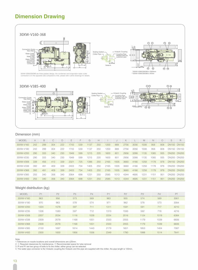
Dimension Drawing
MODEL A B C D E F G H I J K L M N O S R
30XW-V160 242 299 304 222 1743 539 1137 250 1200 889 2756 3056 1008 958 808 DN150 DN150
30XW-V180 242 299 304 222 1743 539 1137 250 1200 889 2756 3056 1008 958 808 DN150 DN150
30XW-V200 290 333 340 230 1949 599 1215 220 1600 801 2956 3288 1135 1085 935 DN200 DN200
30XW-V235 290 333 340 230 1949 599 1215 220 1600 801 2956 3288 1135 1085 935 DN200 DN200
30XW-V308 339 456 413 339 2321 725 1396 250 2165 1005 3660 4166 1258 1178 978 DN150 DN200
30XW-V338 392 491 409 339 2403 734 1405 250 2165 1005 3660 4166 1258 1178 978 DN200 DN200
30XW-V368 392 491 409 339 2403 734 1405 250 2165 1005 3660 4166 1258 1178 978 DN200 DN200
30XW-V385 255 340 358 340 2064 698 1231 250 2585 1013 4344 4695 1231 1151 951 DN200 DN200
30XW-V400 255 340 358 340 2064 698 1231 250 2585 1013 4344 4695 1231 1151 951 DN200 DN200
MODEL P1 P2 P3 P4 P1' P2' P3' P4' PT
30XW-V160 963 956 573 569 963 955 574 569 3061
30XW-V180 970 963 578 574 971 962 578 573 3084
30XW-V200 1324 1578 597 711 1311 1591 591 717 4210
30XW-V235 1326 1580 597 712 1313 1593 592 718 4216
30XW-V308 2207 2034 1116 1028 2224 2016 1124 1019 6384
30XW-V338 2309 2078 1168 1051 2333 2055 1179 1039 6606
30XW-V368 2309 2078 1168 1051 2333 2055 1179 1039 6606
30XW-V385 2133 1697 1814 1443 2179 1651 1853 1404 7087
30XW-V400 2300 1830 1956 1556 2349 1780 1998 1514 7641
Dimension (mm)
Weight distribution (kg)
GH I J
Sealing Gasket Victaulic CouplingCoupling PipeWelded with the customer pipe
Chiller Pipe
Detial A
② ②
①
①
①
M25
**25
100
100
700
700
500
N O
6893000
*
*30XW-V308/338/368 is 3920mm**30XW-V308/338/368 is 40mm
4560 689
1070
990
790
1000
1000
P1 P1'
P2 P2' P4 P4'
①
P2 P2' P4 P4'
P3 P3'
P1 P1' P3 P3'
120
Sealing Gasket Victaulic CouplingCoupling Pipe(Welded with the customer pipe)
Chiller Pipe
Detial A120
F
G
A B
C
D
E
KL
①600
100
100 I J
CIRCUIT B
H
1 600
KL
R
Connection GuideSee Dtail A
SWater Outlet,
CoolerWater Inlet,
CoolerWater Outlet,
CondenserWater Inlet,Condenser
R
Connection GuideSee Dtail A
SWater Outlet,
CoolerWater Inlet,
CoolerWater Outlet,
CondenserWater Inlet,Condenser
ED
C
B
A
F
CIRCUIT A
Note: 1.Tolerances on nozzle locations and overall dimensions are ±25mm. 2. ① Required clearances for maintenance, ② Recommended space for tube removal 3. Pi and Pi' are two group of bolts to fix the chiller, either group can be selected. 4. The water pipe connector is the Victaulic coupling,the Victaulic and the pipe are supplied with the chiller, the pipe length is 120mm.
30XW-V160-368
30XW-V385-400
30XW-V308/338/368 are three passes design, the condenser and evaporator water outlet connection is in the opposite side compared to inlet, please refer outline drawings for details.

14
Basement Drawing
MODEL A(mm) B(mm) C(mm) P(mm) Q(mm) R(mm)30XW-V160 1200 889 3056 985 75 113730XW-V180 1200 889 3056 985 75 113730XW-V200 1600 801 3288 1085 75 121530XW-V235 1600 801 3288 1085 75 121530XW-V308 2165 1005 4166 1258 100 139630XW-V338 2165 1005 4166 1258 100 140530XW-V368 2165 1005 4166 1258 100 140530XW-V385 2585 1013 4695 1151 100 123130XW-V400 2585 1013 4695 1151 100 1231
Chiller outline dimension,more space needed when buliding chiller base
Section diagram for fixing bolts
300
1
00
350
Square hole 100x100to be reserverd for fixing bolts
+2’+2
4’+4 +
3 +3’+
BA
C
P
Q
R
Notes: 1.4 bolts used to fix chiller, bolt size M20×300.2.User can select 1, 2, 3, 4 or 1', 2', 3', 4' as a group to fix bolts.
Notes: 1.Each spider bar must with stand unit weight. 2.Gravity center must be aligned with lifting bar. 3.Loading by lifting lug of condenser is prohibitted.
Dimension Drawing
X
LW
Z
Y
MODEL PT(kg) X(mm) Y(mm) Z(mm) L(mm) min W(mm) min30XW-V160 3061 1447 502 930 2000 120030XW-V180 3084 1447 502 930 2000 120030XW-V200 4210 1382 615 1045 2000 120030XW-V235 4216 1382 615 1045 2000 120030XW-V308 6387 1723 605 1198 4200 140030XW-V338 6606 1723 598 1209 4200 140030XW-V368 6606 1723 598 1209 4200 140030XW-V385 7087 2285 520 1114 4800 140030XW-V400 7641 2285 520 1114 4800 1400
15
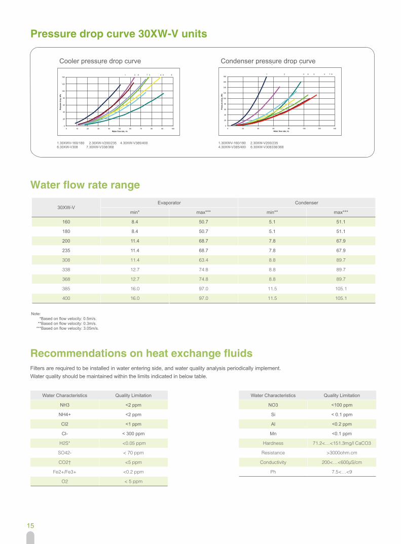
Filters are required to be installed in water entering side, and water quality analysis periodically implement. Water quality should be maintained within the limits indicated in below table.
Pressure drop curve 30XW-V units
Water flow rate range
Recommendations on heat exchange fluids
30XW-VEvaporator Condenser
min* max*** min** max***
160 8.4 50.7 5.1 51.1
180 8.4 50.7 5.1 51.1
200 11.4 68.7 7.8 67.9
235 11.4 68.7 7.8 67.9
308 11.4 63.4 8.8 89.7
338 12.7 74.8 8.8 89.7
368 12.7 74.8 8.8 89.7
385 16.0 97.0 11.5 105.1
400 16.0 97.0 11.5 105.1
Water Characteristics Quality Limitation
NH3 <2 ppm
NH4+ <2 ppm
Cl2 <1 ppm
Cl- < 300 ppm
H2S* <0.05 ppm
SO42- < 70 ppm
CO2† <5 ppm
Fe2+/Fe3+ <0.2 ppm
O2 < 5 ppm
Water Characteristics Quality Limitation
NO3 <100 ppm
Si < 0.1 ppm
Al <0.2 ppm
Mn <0.1 ppm
Hardness 71.2<…<151.3mg/l CaCO3
Resistance >3000ohm.cm
Conductivity 200<…<600µS/cm
Ph 7.5<…<9
Note: *Based on flow velocity: 0.5m/s. **Based on flow velocity: 0.3m/s. ***Based on flow velocity: 3.05m/s.
Cooler pressure drop curve Condenser pressure drop curve
1.30XWV-160/180 2.30XW-V200/235 4.30XW-V385/4006.30XW-V308 7.30XW-V338/368
1.30XWV-160/180 2.30XW-V200/2354.30XW-V385/400 6.30XW-V308338/368
0
20
40
60
80
100
120
140
0 10 20 30 40 50 60 70 80 90 100
Pres
sure
dro
p, k
Pa
Water flow rate, l/s
1 2 6 7 3 4 5 8
0
20
40
60
80
100
120
140
160
180
0 20 40 60 80 100 120 140
Pres
sure
dro
p, k
Pa
Water flow rate, l/s
1 2 3 6 5 4 7 8
0
20
40
60
80
100
120
140
0 10 20 30 40 50 60 70 80 90 100
Pres
sure
dro
p, k
Pa
Water flow rate, l/s
1 2 6 7 3 4 5 8
0
20
40
60
80
100
120
140
160
180
0 20 40 60 80 100 120 140
Pres
sure
dro
p, k
Pa
Water flow rate, l/s
1 2 3 6 5 4 7 8
16
Guide Specifications
General description Factory assembled single piece variable speed water-cooled liquid chiller. Contained within the unit shall be all factory wiring, piping, controls, refrigerant charge (HFC-134a), refrigeration circuits set, screw compressors, variable frequency drive, electronic expansion valves and equipment required prior to field start-up. Size Range: 161 to 407 Tons (567 to 1432 kW) Nominal Carrier Model Number: 30XW-V xxx
Part 1 — General 1.01 SYSTEM DESCRIPTION Microprocessor controlled Variable speed water-cooled liquid chiller utilizing screw compressor, variable frequency drive and electronic expansion valves. 1.02 QUALITY ASSURANCE Unit performance shall be rated in accordance with AHRI Standard 550/590. Unit shall be designed and constructed to meet GB9237-2001Mechanical refrigeration system safety requirement and GB5226.1- 2002 Safety of machinery-Electrical equipment of machines. Unit shall be designed, manufactured and tested in a facility with a quality management system certified ISO 9001 and environmental management system ISO 14001. 1.03 DELIVERY, STORAGE, AND HANDLING Unit shall be capable of withstanding 60°C storage without damage, failure, refrigerant loss, or safety risks. Chiller should be stored indoors, protected from construction dirt and moisture. An inspection should be conducted under shipping tarps, bags, or crates to be sure water has not collected during transit. Protective shipping covers should be kept in place until machine is ready for installation.
Part 2 — Products 2.01 General: Factory assembled, single-piece, variable speed water-cooled liquid chiller. Unit sizes 165-235 shall have single independent refrigerant circuit. Unit sizes 330-460 shall have dual independent refrigerant circuit. Contained within the unit cabinet shall be all factory wiring, piping, controls, refrigerant charge (HFC-134a) and special features required prior to field start-up. 2.02 Compressor (s) : 06T semi-hermetic twin-screw compressors with internal relief valve and check valve to avoid reverse rotation on shut down. Each compressor is equipped with discharge shut-off valve (optional) . Compressor capacity control is ensured by successive use of speed variation (using a variable frequency drive) and swept volume variation at the screws (ensured by the slide valve) , capable of reducing compressor capacity down to 20% of full load. Compressor shall start in unloaded condition. Motor shall be cooled by suction gas and protected by internal winding temperature sensors. Compressor bearings shall be designed for minimum 73000 hours at maximum operating conditions. Lubrication oil system shall include pre-filter and external filter capable of filtration to 5 microns. 2.03 Evaporator: Evaporator shall be manufactured, tested and stamped in accordance with the NB/T 47012-2010(JB/T 4750) and TSG R004-2009. The maximum refrigerant-side working pressure will be 1500 kPa and the maximum waterside pressure will be 1000 kPa (1600, 2100kPa as an option). The evaporator shall be mechanically cleanable, shell-and-tube type with removable heads. Tubes shall be internally and externally grooved, seamless-copper, and shall be rolled into tube sheets. Shall be equipped with victaulic fluid connections or flanged fluid connections. Shell shall be insulated with 19 mm closed-cell foam with a maximum K factor of 0.28. Evaporator thermal insulation shall be factory fitted. The evaporator shall have a drain and vent in each head.

17
Guide Specifications
The evaporator shall incorporate an active refrigerant level control system to ensure optimum heat transfer performance under all load conditions. Evaporator shall be fitted with electronic auto setting water flow switch. 2.04 Condenser: Condenser shall be manufactured, tested and stamped in accordance with the NB/T 47012-2010(JB/T 4750) and TSG R004-2009. The maximum refrigerant-side working pressure will be 1500 kPa and the maximum waterside pressure will be 1000 kPa (1600, 2100kPa as an option). The condenser shall be mechanically cleanable shell-and-tube type with removable heads. Tubes shall be internally and externally grooved, seamless-copper, and shall be rolled into tube sheets. Shall be equipped with victaulic fluid connections or flanged fluid connections. The condenser shall have a drain and vent in each head. 2.05 Refrigeration Components: Refrigerant circuit components shall include, compressor, oil separator, high and low side pressure relief devices, compressor discharge shutoff valves (optional), refrigerant liquid sub assembly line, filter driers, moisture indicating sight glasses, long stroke electronic expansion device, and complete operating charge of both refrigerant HFC-134a and compressor oil. To facilitate service and maintenance and avoid refrigerant charge transfers, it must be possible to isolate the following components and systems independently: filter driers, oil filters. 2.06 Touch pilot colorful screen user interface: This touch pilot colorful screen user interface allow customer to select menu or action by pressing directly on the screen. It is recom mended to use a pen for the navigation via the touch screen. It prevents screen maintenance and allows more precision during the selections. 2.07 Variable frequency drive: 30XW-V/30XW-V Heating units are equipped with a frequency variator that permits compressor capacity adjustment by varying the motor speed in the 30-60 Hz frequency range. The compressor drive uses power supply waveform generation with variable frequency and voltage, generated by pulse width modulation (PWM). Compressor start-up and stopping and the frequency setting for the operating range is only by RS485 communication in the LEN protocol via the Carrier controller. One of the other frequency variator functions is to ensure the unit safety stop function using wired pressure switches at the digital drive inputs. 2.08 Controls (Pro-dialog 7): Unit controls shall include the following minimum components: Microprocessor with non-volatile memory, picture guided unit/operator interface, the LOCAL/OFF/REMOTE/CCN selector and a display with multiple language capability. Pressure sensors shall be installed to measure suction, discharge and oil pressure. Thermostats shall be installed to measure cooler entering and leaving temperatures (on cooler and condenser side). Unit controls shall include the following functions: Automatic change-over and cycling of compressors to equalize running hours and number of starts. EXV control, based on throttling optimizes evaporator charging, ensuring condenser superheat and sub-cooling. Capacity control based on leaving chilled fluid temperature with return fluid temperature sensing. Limit the chilled fluid temperature pull-down rate at start-up to an adjustable range of 0.1℃ to 1.1℃ per minute to prevent excessive demand spikes at start-up. Enable reset of leaving chilled water temperature according to the return water temperature or by means of a 0-10V signal. Provide a dual set point for the leaving chilled water temperature activated by a remote contact closure signal or by the built in time clock. Enable a 2-level demand limit control (between 0 and 100%) or a maximum current drawn limit activated by a remote contact closure or by the built in time clock. Control evaporator water pump and the condenser pump. Allow two time scheduling programs to enable unit start-up control, demand limit and set-point changes. Enable lead lag control of two chillers running in series or parallel.
18
Guide Specifications
2.09 Diagnostics: Display module shall be capable of displaying set points, system status including temperatures, pressures, current for each compressor, run time and percent loading. The control system shall allow a quick test of all machine elements to verify the correct operation of every switch before the chiller is started. 2.10 Safeties: Unit shall be equipped with all necessary components, and in conjunction with the control system shall provide the unit with protection against the following: - Reverse rotation. - Low chilled water temperature. - Low oil pressure (per compressor). - Current imbalance. - Compressor thermal overload - Automatic compressor unloading in case of excessive condensing temperature - High pressure. - Electrical overload. - Loss of phase. - Variable speed drive failure Control shall provide separate general alert (minor incident) and alarm (circuit down) remote indication. 2.11 Operating Characteristics: Unit shall be capable of starting with 13℃ entering water temperature to the condenser. Unit shall be capable of starting with 35℃ entering water temperature to the evaporator. 2.12 Electrical Characteristics: Unit shall operate on 3-phase power supply (400V-3-50Hz) without neutral. Control voltage shall be supplied by a factory-installed transformer. Unit shall be supplied with factory-installed electrical disconnect/isolator switch integrating main fuses. Unit shall have a factory installed variable frequency drive as standard to well control the electrical inrush current below maximum operation current. 2.13 Option Features: Energy Management Module: A factory or field installed module shall provide the following energy management apabilities: 4 to 20 mA signals for leaving fluid temperature reset, cooling set point reset or demand limit control; 2-point demand limit control (from 20 to 100%) activated by a remotcontact closure; and discrete input for “Ice Done” indication for ice storage system interface. BACnet Translator Control: Unit shall be supplied with factory or field-installed interface between the chiller and a BACnet Local Area Network (LAN, i.e., MS/TP EIA-485). LON Translator Control: Unit shall be supplied with factory or field-installed interface between the Chiller and a Local Operating Network (LON, i.e., Lon Works FT-10A ANSI/EIA-709.1). BACnet Communication:
Shall provide factory installed communication capability with a BACnet MS/TP network and allows integration with i-Vu® Open control system or a BACnet building automation system. Medium Temperature Brine: Unit shall be factory modified to start and operate at leaving chilled fluid temperatures below 3.3 ℃ . Chiller shall be equipped with condenser water flow switch. Marine Waterboxes: Marine waterboxes shall provide water piping connections extending from the side of the waterbox (as opposed to extending from the end of the waterbox).This option also includes a removable bolt on waterbox cover allowing access to the heat exchanger tubes without breaking the existing field piping. This option is available for both the evaporator and condenser. Heat machine: Heat machine condensers shall include factory-installed thermal insulation on the condenser, condenser flow switch and leaving water temperature sensor. Heat machine units require field-installed thermal insulation on waterbox heads because of high temperature.
The Manufacturer reserves the right to change any produt specifications without prior notices CAT_30XWV_E-1511_07(AU)
Effective date:
Version:
Supersede:
Nov, 2015
CAT_30XWV_E-1409_06(AU)